JP2013190870A - Image display apparatus and image display method - Google Patents
Image display apparatus and image display method Download PDFInfo
- Publication number
- JP2013190870A JP2013190870A JP2012055003A JP2012055003A JP2013190870A JP 2013190870 A JP2013190870 A JP 2013190870A JP 2012055003 A JP2012055003 A JP 2012055003A JP 2012055003 A JP2012055003 A JP 2012055003A JP 2013190870 A JP2013190870 A JP 2013190870A
- Authority
- JP
- Japan
- Prior art keywords
- display
- image
- displayed
- touch
- screen
- Prior art date
- Legal status (The legal status is an assumption and is not a legal conclusion. Google has not performed a legal analysis and makes no representation as to the accuracy of the status listed.)
- Granted
Links
Images


Classifications
-
- G—PHYSICS
- G06—COMPUTING; CALCULATING OR COUNTING
- G06F—ELECTRIC DIGITAL DATA PROCESSING
- G06F3/00—Input arrangements for transferring data to be processed into a form capable of being handled by the computer; Output arrangements for transferring data from processing unit to output unit, e.g. interface arrangements
- G06F3/14—Digital output to display device ; Cooperation and interconnection of the display device with other functional units
-
- G—PHYSICS
- G06—COMPUTING; CALCULATING OR COUNTING
- G06T—IMAGE DATA PROCESSING OR GENERATION, IN GENERAL
- G06T3/00—Geometric image transformation in the plane of the image
- G06T3/40—Scaling the whole image or part thereof
-
- G—PHYSICS
- G06—COMPUTING; CALCULATING OR COUNTING
- G06F—ELECTRIC DIGITAL DATA PROCESSING
- G06F3/00—Input arrangements for transferring data to be processed into a form capable of being handled by the computer; Output arrangements for transferring data from processing unit to output unit, e.g. interface arrangements
- G06F3/01—Input arrangements or combined input and output arrangements for interaction between user and computer
- G06F3/048—Interaction techniques based on graphical user interfaces [GUI]
- G06F3/0481—Interaction techniques based on graphical user interfaces [GUI] based on specific properties of the displayed interaction object or a metaphor-based environment, e.g. interaction with desktop elements like windows or icons, or assisted by a cursor's changing behaviour or appearance
-
- G—PHYSICS
- G06—COMPUTING; CALCULATING OR COUNTING
- G06F—ELECTRIC DIGITAL DATA PROCESSING
- G06F3/00—Input arrangements for transferring data to be processed into a form capable of being handled by the computer; Output arrangements for transferring data from processing unit to output unit, e.g. interface arrangements
- G06F3/01—Input arrangements or combined input and output arrangements for interaction between user and computer
- G06F3/048—Interaction techniques based on graphical user interfaces [GUI]
- G06F3/0484—Interaction techniques based on graphical user interfaces [GUI] for the control of specific functions or operations, e.g. selecting or manipulating an object, an image or a displayed text element, setting a parameter value or selecting a range
-
- G—PHYSICS
- G06—COMPUTING; CALCULATING OR COUNTING
- G06T—IMAGE DATA PROCESSING OR GENERATION, IN GENERAL
- G06T11/00—2D [Two Dimensional] image generation
- G06T11/60—Editing figures and text; Combining figures or text
-
- G—PHYSICS
- G06—COMPUTING; CALCULATING OR COUNTING
- G06T—IMAGE DATA PROCESSING OR GENERATION, IN GENERAL
- G06T7/00—Image analysis
- G06T7/60—Analysis of geometric attributes
-
- G—PHYSICS
- G06—COMPUTING; CALCULATING OR COUNTING
- G06V—IMAGE OR VIDEO RECOGNITION OR UNDERSTANDING
- G06V30/00—Character recognition; Recognising digital ink; Document-oriented image-based pattern recognition
- G06V30/40—Document-oriented image-based pattern recognition
- G06V30/41—Analysis of document content
- G06V30/413—Classification of content, e.g. text, photographs or tables
-
- G—PHYSICS
- G06—COMPUTING; CALCULATING OR COUNTING
- G06V—IMAGE OR VIDEO RECOGNITION OR UNDERSTANDING
- G06V30/00—Character recognition; Recognising digital ink; Document-oriented image-based pattern recognition
- G06V30/40—Document-oriented image-based pattern recognition
- G06V30/41—Analysis of document content
- G06V30/414—Extracting the geometrical structure, e.g. layout tree; Block segmentation, e.g. bounding boxes for graphics or text
Abstract
Description
本発明は画像データを小さい画面で閲覧するのに適した画像表示装置および画像表示方法に関する。 The present invention relates to an image display device and an image display method suitable for browsing image data on a small screen.
従来、パーソナルコンピュータやPDA、スマートフォン、タブレットなど比較的小さな画像表示装置によって、画素数の大きい文書ページ画像を表示する際に、ページ画像の一部を逐次的に表示することが行われている。一般にページ画像は段落や見出し、図、写真、表などのレイアウト要素からなる複数の部分から構成される。文書を読み進めるために順次、ページの所望の範囲が表示装置に表示されるように、ユーザはスクロールや拡大縮小の操作を繰り返す必要がある。
表示部分のスクロールや拡大縮小は、スイッチやホイール、トラックボール、ジョイスティック、タッチスクリーンなどの操作入力装置を操作することによって行う。特に高精度なタッチスクリーンを用いた装置では、スワイプ操作による縦・横・斜めの任意の方向へのスクロールと、ピンチアウトおよびピンチイン操作による拡大縮小という、直接的な操作感(ダイレクトマニピュレーション)が普及している。
特許文献1には、一次元的な操作(右矢印キーの操作)によって、文書画像の読み順に従って二次元的に画面をスクロールすることで、文書画像内の各領域を順番に画面上に等倍表示する方法が開示されている。
Conventionally, when a document page image having a large number of pixels is displayed by a relatively small image display device such as a personal computer, a PDA, a smartphone, or a tablet, a part of the page image is sequentially displayed. In general, a page image is composed of a plurality of parts composed of layout elements such as paragraphs, headings, figures, photographs, and tables. In order to read the document forward, the user needs to repeat scrolling and scaling operations so that a desired range of pages is sequentially displayed on the display device.
The display portion is scrolled and enlarged / reduced by operating an operation input device such as a switch, a wheel, a trackball, a joystick, or a touch screen. Especially for devices using high-precision touch screens, direct manipulations such as scrolling in any vertical, horizontal, and diagonal directions by swiping operations and scaling by pinch-out and pinch-in operations are popular. doing.
In
しかしながら、スワイプ操作による任意の方向へのスクロールとピンチアウト/ピンチイン操作による拡大縮小操作によってページ画像を読み進めていく場合、ユーザ所望の範囲がちょうど画面内に表示されるように大きさや位置を微調整する手間がかかり煩雑だった。
また、特許文献1の方法では、矢印キーの操作に応じて各領域を読み順にしたがって順番に等倍表示するので、各領域の表示サイズを調整することはできなかった。また、特許文献1は矢印キーを用いて操作を行うものであり、ユーザによるスワイプ操作や拡大縮小操作が為された場合については考慮されていなかった。
However, when a page image is read by scrolling in any direction by swipe operation and scaling operation by pinch-out / pinch-in operation, the size and position are finely adjusted so that the desired range is displayed on the screen. It took time and effort to make adjustments.
Further, in the method of
上記課題を解決するために、本発明の画像表示装置は、複数のオブジェクトを含む画像を表示する画像表示装置であって、前記画像に含まれる各オブジェクトを表示する第1の表示モードが指定された場合、表示対象のオブジェクトの属性に応じて、表示倍率と表示位置とを設定する設定手段と、前記設定手段で設定された前記表示倍率と前記表示位置とに基づいて、当該表示対象のオブジェクトを含む前記画像を画面に表示するように制御する表示制御手段と、を有することを特徴とする。 In order to solve the above problems, an image display device of the present invention is an image display device that displays an image including a plurality of objects, and a first display mode for displaying each object included in the image is designated. In the case of the display target, the display unit sets the display magnification and the display position according to the attribute of the display target object, and the display target object based on the display magnification and the display position set by the setting unit. Display control means for controlling to display the image including the image on a screen.
本発明によれば、オブジェクトを表示する第1の表示モードでは、各オブジェクトの属性に応じて、各オブジェクトを見やすい形で画面に表示させることができる。 According to the present invention, in the first display mode for displaying objects, each object can be displayed on the screen in an easy-to-see manner according to the attribute of each object.
[実施例1]
図1は、本実施形態に係る画像処理システムの構成を示すブロック図である。
[Example 1]
FIG. 1 is a block diagram illustrating a configuration of an image processing system according to the present embodiment.
図1において、オフィス内に構築されたLAN102には、複数種類の機能(複写機能、印刷機能、送信機能等)を実現する複合機であるMFP100と、クライアントPC101が接続されている。さらにLAN102には、プロキシサーバ103と、文書管理サーバ106、文書管理サーバ106のためのデータベース105、携帯情報端末107が、無線または有線で接続されている。LAN102は、また、プロキシサーバ103を介してネットワーク104に接続されている。クライアントPC101では、例えば、印刷データをMFP100へ送信することで、その印刷データに基づく印刷物をMFP100で印刷することが可能である。なお、図1の構成は一例であり、同様の構成要素を有する複数のオフィスがネットワーク104上に接続されていても良い。
In FIG. 1, a
クライアントPC101、プロキシサーバ103の各種端末はそれぞれ、汎用コンピュータに搭載される標準的な構成要素(例えば、CPU、RAM、ROM、ハードディスク、ネットワークI/F、ディスプレイ、キーボード、マウス等)を有している。また、ネットワーク104は、典型的にはインターネットやLANやWANや電話回線、専用デジタル回線、ATMやフレームリレー回線、通信衛星回線、ケーブルテレビ回線、データ放送用無線回線等のいずれかで実現されている。もちろん、それらの組み合わせにより実現されるいわゆる通信ネットワークであっても良いことは言うまでもなく、データの送受信が可能であれば良い。
Each terminal of the client PC 101 and the
図2は、図1におけるMFP100の機能構成を示すブロック図である。図2において、MFP100は、画像読み取り部110、記憶装置(以下、BOX)111、記録装置112、データ処理装置115、入力装置113、表示装置116、ネットワークI/F114で構成される。画像読み取り部110は、図示しないAuto Document Feeder(以下、ADF)を有し、束状の或いは1枚の原稿の画像を光源で照射し、反射画像をレンズで固体撮像素子上に結像する。固体撮像素子は所定解像度(例えば600dpi)および所定輝度レベル(例えば8ビット)の画像読み取り信号を生成し、画像読み取り信号からラスターデータよりなる画像データが構成される。通常の複写機能を実行する際には、画像読み取り部110で得たビットマップ画像データをデータ処理装置115によって、後述するスキャン画像処理して記録信号に変換し、記録装置112で画像形成(印刷出力)する。複数枚複写の場合には、1頁分の記録信号を一旦BOX111に記憶保持した後、記録装置112に順次出力して、記録紙上に記録画像を形成する。MFP100は、ローカルPC102(もしくは他の汎用PC(不図示))からドライバを利用して出力されてくるPDLデータを、LAN102とネットワークI/F114を介して受信し、当該受信したPDLデータに基づく画像を、記録装置112によって記録し得る。すなわち、ローカルPC102からドライバを経由して出力されるPDLデータは、LAN107からネットワークI/F114を経てデータ処理装置115に入力される。そこで言語を解釈・処理することで記録可能な記録信号に変換された後、MFP100において、記録紙上に記録画像として記録される。
FIG. 2 is a block diagram showing a functional configuration of
BOX111は、画像読み取り部110からのデータやローカルPC102からドライバを経由して出力されるPDLデータをレンダリングしたデータを保存できる機能を有している。また、MFP100は、MFP100に設けられたキー操作部(入力装置113)を通じて操作され、操作入力の状態を表示装置116によって表示し得る。
The
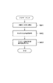
次に、図3を用いて、本実施例におけるアプリケーション画像データの生成フローを説明する。 Next, the generation flow of application image data in the present embodiment will be described with reference to FIG.
図3は、MFP100の画像読み取り部110により取得されたビットマップ画像データや、ローカルPC102上においてアプリケーションソフトで作成されたドキュメントをMFP100内部でレンダリングして生成したビットマップ画像データから、携帯情報端末107で表示するための所定のフォーマットのデータ(以下ではアプリケーション画像データと呼ぶこととする)を生成するためのフローチャートである。
FIG. 3 illustrates the
まず、ステップS301において、データ処理装置115は、ビットマップ画像データを属性毎のオブジェクトに分割するオブジェクト分割処理を行う。オブジェクト分割後のオブジェクトの属性種類は、文字、写真、グラフィック(図面、線画、表、ライン)、背景を指す。分割された各々のオブジェクトに対して、ステップS302において、オブジェクトの種類(文字、写真、グラフィック、背景)を判定する。写真または背景と判定されたオブジェクトについては、ステップS303において、当該オブジェクトのビットマップ画像をJPEG圧縮する。一方、文字またはグラフィックと判定されたオブジェクトについては、ステップS304において、ベクトル化処理を行って、パス化されたデータ(ベクトルデータ)に変換する。次に、ステップS305において該オブジェクトが文字であるか判定し、文字の場合には、更にステップS308において、OCR処理を施し、文字コード化されたデータ(OCR結果の文字コードデータ)も取得する。S303及びS304で得た各オブジェクトのデータ(JPEGデータ、ベクトルデータ)と、S308で得た文字コードデータとを一つのファイルにまとめた後、ステップS306において、各オブジェクトに対して、最適なメタデータを付与する。メタデータが付与された各々のオブジェクトは、ステップS307において、携帯情報端末107が表示可能なアプリケーション画像データに生成される。最後に、ステップS309において、データ処理装置115は、生成したアプリケーション画像データを携帯情報端末107に送信する。
First, in step S301, the
次に、図4と図5を用いて、本実施例におけるビットマップ画像データ(文書画像データ)の作成について説明する。図4は、MFP100の画像読み取り部110を使用した場合のビットマップ画像データ作成のフローチャート、図5は、PC102上のアプリケーションを使用した場合のフローチャートである。図4または図5で生成されたビットマップ画像データに対して、上述した図3の処理が実行される。
Next, creation of bitmap image data (document image data) in the present embodiment will be described with reference to FIGS. 4 is a flowchart for creating bitmap image data when the
MFP100の画像読み取り部110を使用した場合には、図4のステップS401において、画像を読み込む。読み込まれた画像は、既にビットマップ画像データである。ステップS402において、そのビットマップ画像データに対して、画像読み取り部110に依存するスキャナ画像処理を行う。ここで言うスキャナ画像処理とは、例えば、色処理やフィルタ処理を指す。
When the
PC102上のアプリケーションを使用した場合には、まず、図5のステップS501において、PC102上のアプリケーションを使用して作成したデータが、PC102上にあるプリントドライバを介してプリントデータに変換され、MFP100に送信される。ここで言うプリントデータとは、PDLを意味し、例えば、LIPS(商標)、Postscript(商標)等のページ記述言語を指す。次にステップS502において、MFP100内部に存在するインタープリタを介して、ディスプレイリストが生成される。そのディスプレイリストをステップS503において、レンダリングすることにより、ビットマップ画像データが生成される。
When the application on the
図6のフローチャートを用いて、図3のステップS306に示すメタデータの付与処理の詳細について説明する。 Details of the metadata adding process shown in step S306 of FIG. 3 will be described with reference to the flowchart of FIG.
まず、ステップS601において、S301で分割されたオブジェクトのそれぞれについて、各オブジェクトの周囲で一番近くに存在する文字オブジェクトを選択する。次に、ステップS602において、選択された文字オブジェクトに対して、形態素解析を行う。次に、ステップS603において、前記ステップS602で形態素解析結果により抽出された単語をメタデータとして各オブジェクトに付加する。 First, in step S601, for each of the objects divided in S301, a character object that is closest to each other around each object is selected. In step S602, morphological analysis is performed on the selected character object. In step S603, the word extracted from the morphological analysis result in step S602 is added to each object as metadata.
なお、メタデータは、形態素解析だけではなく、画像特徴量抽出、構文解析等によっても作成できる。さらに、MFP100に内蔵されたBOX、およびデータベース105に既に保存されている文書、および、それに含まれるオブジェクトを対象に類似画像検索を行って、類似度の高い類似画像のオブジェクトとの関連付けを行っても良い。
Metadata can be created not only by morphological analysis but also by image feature extraction, syntax analysis, and the like. Further, a similar image search is performed on a BOX built in
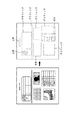
次に、図7と図8を用いて、前記ステップS301のオブジェクト分割について、詳細に説明する。図7は、オブジェクト分割処理によって、ビットマップ画像データを複数のオブジェクトに分割した結果の一例である。図8は、オブジェクト分割したときの各オブジェクトのブロック情報および入力ファイル情報を表す。 Next, the object division in step S301 will be described in detail with reference to FIGS. FIG. 7 is an example of the result of dividing bitmap image data into a plurality of objects by object division processing. FIG. 8 shows block information and input file information of each object when the object is divided.
ステップS301において、入力画像(図7の左)に対してオブジェクト分割処理を行うことにより、属性ごとに矩形ブロックに分割する(図7の右)。前述のように、矩形ブロックの属性としては、文字、写真、グラフィック(図面、線画、表、ライン)がある。オブジェクト分割処理の一手法としては、例えば以下のような手法がある。まず、MFP100内のRAM(不図示)に格納されたイメージデータを白黒に2値化し、黒画素輪郭で囲まれる画素塊を抽出する。さらに、このように抽出された黒画素塊の大きさを評価し、大きさが所定値以上の黒画素塊の内部にある白画素塊に対する輪郭追跡を行う。白画素塊に対する大きさ評価、内部黒画素塊の追跡というように、内部の画素塊が所定値以上である限り、再帰的に内部画素塊の抽出、輪郭追跡を行う。画素塊の大きさは、例えば画素塊の面積によって評価される。このようにして得られた画素塊に外接する矩形ブロックを生成し、矩形ブロックの大きさ、形状に基づき属性を判定する。例えば、縦横比が1に近く、大きさが一定の範囲の矩形ブロックは文字領域矩形ブロックの可能性がある文字相当ブロックとする。また、近接する文字相当ブロックが規則正しく整列しているときに、これら文字相当ブロックを纏めた新たな矩形ブロックを生成し、新たな矩形ブロックを文字領域矩形ブロックとする。また扁平な画素塊、もしくは、一定大きさ以上でかつ四角形の白画素塊を整列よく内包する黒画素塊をグラフィック領域矩形ブロック、それ以外の不定形の画素塊を写真領域矩形ブロックとする。
In step S301, object division processing is performed on the input image (left in FIG. 7) to divide each attribute into rectangular blocks (right in FIG. 7). As described above, the attributes of rectangular blocks include characters, photographs, and graphics (drawings, line drawings, tables, lines). As one method of object division processing, for example, the following methods are available. First, image data stored in a RAM (not shown) in the
ステップS301では、このようにして生成された矩形ブロックのそれぞれについて、図8に示す、属性等のブロック情報および入力ファイル情報を生成する。図8において、ブロック情報には各ブロックの属性、位置の座標X、座標Y、幅W、高さH、OCR情報が含まれる。属性は1〜3の数値で与えられ、1は文字領域矩形ブロック、2は写真領域矩形ブロック、3はグラフィック領域矩形ブロックを示す。座標X、座標Yは入力画像における各矩形ブロックの始点のX、Y座標(左上角の座標)である。幅W、高さHは矩形ブロックのX座標方向の幅、Y座標方向の高さである。OCR情報は、前記ステップS308のOCR処理で文字コード化されたデータへのポインタ情報の有無を示す。さらに入力ファイル情報として矩形ブロックの個数を示すブロック総数Nも保存しておく。 In step S301, block information such as attributes and input file information shown in FIG. 8 are generated for each of the rectangular blocks generated in this way. In FIG. 8, the block information includes the attribute of each block, position coordinates X, coordinates Y, width W, height H, and OCR information. The attribute is given by a numerical value of 1 to 3, where 1 is a character area rectangular block, 2 is a photo area rectangular block, and 3 is a graphic area rectangular block. The coordinates X and Y are the X and Y coordinates (upper left corner coordinates) of the start point of each rectangular block in the input image. The width W and the height H are the width in the X coordinate direction and the height in the Y coordinate direction of the rectangular block. The OCR information indicates the presence / absence of pointer information to the data that has been character-coded in the OCR process of step S308. Further, the total number N of blocks indicating the number of rectangular blocks is also stored as input file information.
これらの矩形ブロックごとのブロック情報は、特定領域でのベクトル化に利用される。またブロック情報によって、特定領域とその他の領域を合成する際の相対位置関係を特定でき、入力画像のレイアウトを損なわずにベクトル化された領域とビットマップのままの領域を合成することが可能となる。 The block information for each rectangular block is used for vectorization in a specific area. In addition, the relative positional relationship when combining specific areas with other areas can be specified by block information, and vectorized areas and bitmap areas can be combined without impairing the layout of the input image. Become.
次に、図9のフローチャートを用いて、図3のステップS304のベクトル化処理について詳細に説明する。 Next, the vectorization process in step S304 of FIG. 3 will be described in detail using the flowchart of FIG.
まず、ステップS901において、データ処理装置115は、特定領域が文字領域矩形ブロックであるか否か判断し、文字領域の矩形ブロックであればステップS902以下のステップに進む。一方、特定領域が文字領域矩形ブロックでないときは、ステップS912に移行する。
First, in step S901, the
ステップS902〜S907では、パターンマッチング等の手法を用いて文字認識処理を行い、対応する文字コードを得る。例えば、ステップS902において、データ処理装置115は、特定領域に対し横書き、縦書きの判定(組み方向判定)を行うために、特定領域内で画素値に対する水平・垂直の射影を取る。次に、ステップS903において、ステップS902の射影の分散を評価する。水平射影の分散が大きい場合は横書き、垂直射影の分散が大きい場合は縦書きと判断する。ステップS904において、ステップS903の評価結果に基づき、組み方向を判定し、行の切り出しを行い、その後文字を切り出して文字画像を得る。文字列および文字への分解は、横書きならば水平方向の射影を利用して行を切り出し、切り出された行に対する垂直方向の射影から、文字を切り出す。縦書きの文字領域に対しては、水平と垂直について逆の処理を行う。行、文字切り出しに際して、文字のサイズも検出し得る。次に、ステップS905において、ステップS904で切り出された各文字について、文字画像から得られる特徴を数十次元の数値列に変換した観測特徴ベクトルを生成する。特徴ベクトルの抽出には種々の公知手法があり、例えば、文字をメッシュ状に分割し、各メッシュ内の文字線を方向別に線素としてカウントしたメッシュ数次元ベクトルを特徴ベクトルとする方法がある。ステップS906において、ステップS905で得られた観測特徴ベクトルと、あらかじめフォントの種類ごとに求められている辞書特徴ベクトルとを比較し、観測特徴ベクトルと辞書特徴ベクトルとの距離を算出する。ステップS907において、ステップS906で算出された距離を評価し、最も距離の近いフォントの種類を認識結果とする。
In steps S902 to S907, character recognition processing is performed using a method such as pattern matching to obtain a corresponding character code. For example, in step S <b> 902, the
次に、ステップS908において、ステップS907における距離評価の最短距離が所定値よりも大きいか否か、類似度を判断する。最短距離が所定値以上の場合(類似度が低い場合)は、辞書特徴ベクトルにおいて、形状が類似する他の文字に誤認識している可能性が高い。そこで最短距離が所定値以上の場合(類似度が低い場合)は、ステップS907の認識結果を採用せず、ステップS911の処置に進む。類似度が所定値より小さいとき(類似度が高い場合)は、ステップS907の認識結果を採用し、ステップ909に進む。 Next, in step S908, it is determined whether or not the shortest distance for distance evaluation in step S907 is greater than a predetermined value. When the shortest distance is greater than or equal to a predetermined value (when the degree of similarity is low), there is a high possibility that the dictionary feature vector is erroneously recognized as another character having a similar shape. Therefore, if the shortest distance is equal to or greater than a predetermined value (when the similarity is low), the recognition result in step S907 is not adopted, and the process proceeds to step S911. When the similarity is smaller than a predetermined value (when the similarity is high), the recognition result of step S907 is adopted, and the process proceeds to step 909.
ステップS909では、文字フォントの種類を認識する。文字認識の際に用いる、フォントの種類数分の辞書特徴ベクトルを、文字形状種すなわちフォント種に対して複数用意しておく。これを、パターンマッチングの際に、文字コードとともにフォント種を出力することで、文字フォントを認識し得る。次に、ステップS910において、文字認識およびフォント認識よって得られた文字コードおよびフォント情報を用いて、各々あらかじめ用意されたアウトラインデータを用いて、各文字をベクトルデータに変換する。なお、入力画像がカラーの場合は、カラー画像から各文字の色を抽出してベクトルデータとともに記録する。 In step S909, the type of character font is recognized. A plurality of dictionary feature vectors corresponding to the number of font types used for character recognition are prepared for character shape types, that is, font types. By outputting the font type together with the character code at the time of pattern matching, the character font can be recognized. In step S910, each character is converted into vector data using outline data prepared in advance using the character code and font information obtained by character recognition and font recognition. When the input image is color, the color of each character is extracted from the color image and recorded together with vector data.
一方、ステップS911では、文字をグラフィックと同様に扱い、該文字をアウトライン化する。すなわち誤認識を起こす可能性の高い文字については、見かけ上ビットマップに忠実なアウトラインのベクトルデータを生成する。 On the other hand, in step S911, the character is handled in the same manner as a graphic, and the character is outlined. That is to say, for characters that are likely to cause erroneous recognition, outline vector data that is apparently faithful to the bitmap is generated.
また、ステップS912では、特定領域が文字領域矩形ブロックでないとき(すなわちグラフィック領域矩形ブロックのとき)、画像の輪郭に基づいてベクトル化の処理を実行する。 In step S912, when the specific area is not a character area rectangular block (that is, a graphic area rectangular block), vectorization processing is executed based on the contour of the image.
以上の処理により、文字領域矩形ブロックおよびグラフィック領域矩形ブロックに属するイメージ情報をベクトルデータに変換出来る。 Through the above processing, the image information belonging to the character area rectangular block and the graphic area rectangular block can be converted into vector data.
図10と図11、図12を用いて、ステップS912のグラフィック領域矩形ブロックのベクトル化処理について詳細に説明する。グラフィック領域矩形ブロックのベクトル化処理は、該領域内で抽出された黒画素塊の輪郭に基づいてベクトル化を行う。図10は、ベクトル化の処理における角抽出の処理を示す図、図11は、ベクトル化の処理における輪郭線まとめの処理を示す図である。図12は、グラフィック領域のベクトル化処理の詳細フローチャートである。図12のステップS1201において、データ処理装置115は、線画等を直線および/または曲線の組み合わせとして表現するために、曲線を複数の区間(画素列)に区切る「角」を検出する。角とは曲率が極大となる点であり、図10に示すように、曲線上の画素Piが角か否かの判断は以下のように行う。すなわち、Piを起点とし、曲線に沿ってPiから両方向に所定画素(k個とする)ずつ離れた画素Pi−k、Pi+kを線分Lで結ぶ。画素Pi−k、Pi+k間の距離をd1、線分Lと画素Piとの距離をd2、曲線の画素Pi−k 、Pi+k間の弧の長さをAとする。d2が極大となるとき、あるいは比(d1/A)が閾値以下となるときに画素Piを角と判断する。角によって分割された画素列を、直線あるいは曲線で近似する。直線への近似は最小二乗法等により実行し、曲線への近似は3次スプライン関数などを用いる。画素列を分割する角の画素は近似直線あるいは近似直線における、始端または終端となる。さらにベクトル化された輪郭内に白画素塊の内輪郭が存在するか否かを判断し、内輪郭が存在するときはその輪郭をベクトル化し、内輪郭の内輪郭というように、再帰的に反転画素の内輪郭をベクトル化する。以上のように、輪郭の区分線近似を用いれば、任意形状の図形のアウトラインをベクトル化することができる。元原稿がカラーの場合は、カラー画像から図形の色を抽出してベクトルデータとともに記録する。
The vectorization processing of the graphic area rectangular block in step S912 will be described in detail with reference to FIG. 10, FIG. 11, and FIG. The vectorization processing of the graphic area rectangular block performs vectorization based on the outline of the black pixel block extracted in the area. FIG. 10 is a diagram illustrating corner extraction processing in vectorization processing, and FIG. 11 is a diagram illustrating outline grouping processing in vectorization processing. FIG. 12 is a detailed flowchart of vectorization processing of the graphic area. In step S1201 of FIG. 12, the
ステップS1202では、ステップS1201で求めた輪郭線が近接している場合はそれらをまとめて太さを持った線とする処理を行う。図11に示すように、ある注目区間で外輪郭PRjと、内輪郭PRj+1あるいは別の外輪郭が近接している場合、2個あるいは複数の輪郭線をひとまとめにし、太さを持った線として表現することができる。例えば、輪郭PRj+1の各画素Piから輪郭PRj上で最短距離となる画素Qiまでの距離PiQiを算出し、PQiのばらつきが僅かである場合には、注目区間を画素Pi、Qiの中点Miの点列に沿った直線または曲線で近似し得る。近似直線、近似曲線の太さは、例えば距離PiQiの平均値とする。線や線の集合体である表罫線は、太さを持つ線の集合とすることにより、効率よくベクトル表現することができる。 In step S1202, if the contour lines obtained in step S1201 are close to each other, a process is performed in which the lines are thickened together. As shown in FIG. 11, when the outer contour PRj and the inner contour PRj + 1 or another outer contour are close to each other in a certain section of interest, two or a plurality of contour lines are combined and expressed as a line having a thickness. can do. For example, the distance PiQi from each pixel Pi of the contour PRj + 1 to the pixel Qi that is the shortest distance on the contour PRj is calculated, and when the variation in PQi is slight, the interval of interest is the midpoint Mi of the pixels Pi and Qi. It can be approximated by a straight line or curve along the point sequence. The thickness of the approximate line and the approximate curve is, for example, an average value of the distance PiQi. A table ruled line, which is a line or a set of lines, can be efficiently expressed as a vector by using a set of lines having a thickness.
ステップS1203において、各ベクトルデータの始点、終点を算出する。 In step S1203, the start point and end point of each vector data are calculated.
ステップS1204において、ステップS1203で求められた始点、終点情報を用いて、図形要素を検出する。図形要素とは、区分線が構成している閉図形であり、検出に際しては、始点、終端となっている共通の角の画素においてベクトルを連結する。すなわち、閉形状を構成する各ベクトルはその両端にそれぞれ連結するベクトルを有しているという原理を応用する。 In step S1204, a graphic element is detected using the start point and end point information obtained in step S1203. A graphic element is a closed graphic formed by a dividing line, and a vector is connected at a common corner pixel serving as a start point and an end point for detection. That is, the principle that each vector constituting the closed shape has a vector connected to both ends thereof is applied.
ステップS1205において、ベクトルデータより両端に連結していない不要なベクトルを除去し、閉図形を構成するベクトルを抽出する。 In step S1205, unnecessary vectors that are not connected to both ends are removed from the vector data, and a vector constituting the closed figure is extracted.
ステップS1206において、閉図形を構成するベクトルについて、いずれかのベクトルの端点(始点または終点)を開始点とし、一定方向、例えば時計回りに、順にベクトルを探索する。すなわち、他端点において他のベクトルの端点を探索し、所定距離内の最近接端点を連結ベクトルの端点とする。閉図形を構成するベクトルを1まわりして開始点に戻ったとき、通過したベクトルを全て一つの図形要素を構成する閉図形としてグループ化する。また、閉図形内部にある閉図形構成ベクトルも全てグループ化する。さらにまだグループ化されていないベクトルの始点を開始点とし、同様の処理を繰り返す。 In step S1206, for the vectors constituting the closed figure, the vectors are searched in order in a certain direction, for example, clockwise, starting from the end point (start point or end point) of any vector. That is, the end point of another vector is searched at the other end point, and the closest end point within a predetermined distance is set as the end point of the connected vector. When the vector constituting the closed figure is rotated by one and returned to the starting point, all the passed vectors are grouped as a closed figure constituting one graphic element. In addition, all closed graphic constituent vectors inside the closed graphic are also grouped. Further, the same processing is repeated with the starting point of a vector not yet grouped as a starting point.
ステップS1207において、ステップS1205で除去された不要ベクトルのうち、ステップS1206で閉図形としてグループ化されたベクトルに端点が近接しているベクトルを検出し、一つの図形要素としてグループ化する。これによって、図形要素内に存在する他の図形要素、もしくは区分線をグループ化し、一つの図形オブジェクトとすることが出来る。また、図形要素内に他の図形要素、区分線が存在しない場合は図形要素を図形オブジェクトとする。 In step S1207, among the unnecessary vectors removed in step S1205, a vector whose end point is close to the vector grouped as a closed graphic in step S1206 is detected and grouped as one graphic element. As a result, other graphic elements or dividing lines existing in the graphic element can be grouped into one graphic object. If there is no other graphic element or dividing line in the graphic element, the graphic element is set as a graphic object.
以上の処理によってグラフィック領域矩形ブロックを、ベクトル化された一つのオブジェクトに変換することが出来る。 The graphic area rectangular block can be converted into one vectorized object by the above processing.
次に、図13と図14を用いて、ステップS307のアプリケーション画像データ生成について詳細に説明する。図13は、本実施例に係るベクトル化処理結果のデータ構成を示すマップである。図14は、アプリケーション画像データ生成処理の詳細を示すフローチャートである。 Next, generation of application image data in step S307 will be described in detail with reference to FIGS. FIG. 13 is a map showing the data structure of the vectorization processing result according to the present embodiment. FIG. 14 is a flowchart showing details of the application image data generation process.
まず、ステップS1401において、ステップS304のベクトル化で生成された中間データを取得する。本実施形態において、中間データは、以下のようなドキュメント・アナリシス・アウトプット・フォーマット(以下、DAOF)と呼ぶ形式で保存されているものとする。図13に示すように、DAOFは、ヘッダ1301、レイアウト記述データ部1302、文字認識記述データ部1303、表記述データ部1304、画像記述データ部1305よりなる。ヘッダ1301には、処理対象の入力画像に関する情報が保持される。レイアウト記述データ部1302には、入力画像中の矩形ブロックの属性である文字、グラフィック(線画、図面 、表、ライン)、写真等の情報と、これら属性が認識された各矩形ブロックの位置情報が保持される。文字認識記述データ部1303には、文字領域矩形ブロックのうち、文字認識して得られる文字認識結果が保持される。表記述データ部1304には、表の属性を持つグラフィック領域矩形ブロックの表構造の詳細が格納される。画像記述データ部1305には、ベクトル化の処理が指示された特定領域においては、ベクトル化処理により得られたブロックの内部構造や、画像の形状や文字コード等あらわすデータの集合が保持される。一方、ベクトル化処理の対象ではない特定領域以外の矩形ブロックでは、オブジェクトに分割されたビットマップ画像データそのものが保持される。
First, in step S1401, intermediate data generated by vectorization in step S304 is acquired. In the present embodiment, it is assumed that the intermediate data is stored in a format called the following document analysis output format (hereinafter referred to as DAOF). As shown in FIG. 13, the DAOF includes a
次に、ステップS1402において、後述する文書構造ツリー生成を行う。 Next, in step S1402, a document structure tree that will be described later is generated.
ステップS1403において、文書構造ツリーを元に、DAOF内の実データを取得し、後述するアプリケーション画像データを生成する。 In step S1403, actual data in the DAOF is acquired based on the document structure tree, and application image data to be described later is generated.
図15と図16、図17を用いて、前記ステップS1402の文書構造ツリー生成について説明する。図15は、文書構造ツリー生成の処理を示すフローチャートである。図16は、文書構造ツリー生成処理の対象となる文書の例を示す図で、図17は、文書構造ツリー生成の処理によって生成される文書構造ツリーを示す図である。 The document structure tree generation in step S1402 will be described with reference to FIG. 15, FIG. 16, and FIG. FIG. 15 is a flowchart showing a document structure tree generation process. FIG. 16 is a diagram illustrating an example of a document that is a target of the document structure tree generation process, and FIG. 17 is a diagram illustrating a document structure tree generated by the document structure tree generation process.
図15に示す文書構造ツリー生成の処理における全体制御の基本ルールとして、処理の流れはミクロブロック(単一矩形ブロック)からマクロブロック(矩形ブロックの集合体)へ移行する。以後「矩形ブロック」は、ミクロブロックおよびマクロブロック両者を意味するものとする。 As a basic rule of overall control in the document structure tree generation process shown in FIG. 15, the flow of processing shifts from a micro block (single rectangular block) to a macro block (an assembly of rectangular blocks). Hereinafter, “rectangular block” means both a micro block and a macro block.
まず、ステップS1501において、データ処理装置115は、矩形ブロック単位で、縦方向の関連性に基づいて、矩形ブロックを再グループ化する。図15の処理は繰り返し実行されることがあるが、処理開始直後はミクロブロック単位での判定となる。ここで、関連性とは、距離が近い、ブロック幅(横方向の場合は高さ)がほぼ同一であることなどの特徴によって定義される。また、距離、幅、高さなどの情報はDAOFを参照し、抽出する。例えば、図16の文書では、最上部で、矩形ブロックT1、T2が横方向に並列されている。矩形ブロックT1、T2の下には横方向セパレータS1が存在し、横方向セパレータS1の下に矩形ブロックT3、T4、T5、T6、T7が存在する。矩形ブロックT3、T4、T5は、横方向セパレータS1下側の領域における左半部において上から下に、縦方向に配列され、矩形ブロックT6、T7は、横方向セパレータS1下側の領域における右半部において上下に配列されている。ステップS1601の縦方向の関連性に基づくグルーピングの処理を実行すると、矩形ブロックT3、T4、T5が1個のグループ(矩形ブロック)V1にまとめられ、矩形ブロックT6、T7が1個のグループ(矩形ブロック)V2にまとめられる。グループV1、V2は同一階層となる。
First, in step S1501, the
次に、ステップS1502において、縦方向のセパレータの有無をチェックする。セパレータは、DAOF中でライン属性を持つオブジェクトであり、明示的にブロックを分割する機能をもつ。セパレータを検出すると、処理対象の階層において、入力画像の領域を、セパレータを境界として左右に分割する。図16では縦方向のセパレータは存在しない。 In step S1502, the presence / absence of a vertical separator is checked. The separator is an object having a line attribute in DAOF and has a function of explicitly dividing a block. When the separator is detected, the area of the input image is divided into left and right with the separator as a boundary in the processing target hierarchy. In FIG. 16, there is no vertical separator.
次に、ステップS1503において、縦方向のグループ高さの合計が入力画像の高さに等しくなったか否か判断する。すなわち縦方向(例えば上から下)に処理対象の領域を移動しながら、横方向のグルーピングを行うとき、入力画像全体の処理が終了したときには、グループ高さ合計が入力画像高さになることを利用し、処理の終了判断を行う。グルーピングが終了したときはそのまま処理終了し、グルーピングが終了していなかったときはステップS1504に進む。 In step S1503, it is determined whether the total vertical group height is equal to the height of the input image. In other words, when performing grouping in the horizontal direction while moving the region to be processed in the vertical direction (for example, from top to bottom), when processing of the entire input image is completed, the total group height becomes the input image height. Use it to determine the end of processing. When the grouping is finished, the process is finished as it is, and when the grouping is not finished, the process proceeds to step S1504.
次に、ステップS1504において、横方向の関連性に基づくグルーピングの処理を実行する。これによって、例えば図16の矩形ブロックT1、T2が1個のグループ(矩形ブロック)H1にまとめられ、矩形ブロックV1、V2が1個のグループ(矩形ブロック)H2にまとめられる。グループH1、H2は同一階層となる。ここでも、処理開始直後はミクロブロック単位での判定となる。 Next, in step S1504, a grouping process based on the relevance in the horizontal direction is executed. Accordingly, for example, the rectangular blocks T1 and T2 in FIG. 16 are combined into one group (rectangular block) H1, and the rectangular blocks V1 and V2 are combined into one group (rectangular block) H2. The groups H1 and H2 are in the same hierarchy. Again, immediately after the start of processing, the determination is made in units of micro blocks.
次に、ステップS1505において、横方向のセパレータの有無をチェックする。セパレータを検出すると、処理対象の階層において、入力画像の領域を、セパレータを境界として上下に分割する。図16では横方向のセパレータS1が存在する。以上の処理結果は図17のツリーとして登録される。図17において、入力された1ページのビットマップ画像データV0は、最上位階層にグループH1、H2、セパレータS1を有し、グループH1には第2階層の矩形ブロックT1、T2が属する。グループH2には、第2階層のグループV1、V2が属し、グループV1には、第3階層の矩形ブロックT3、T4、T5が属し、グループV2には、第3階層の矩形ブロックT6、T7が属する。本実施例において、V0はページを表し、V0の下位階層にあるものがオブジェクトとなる。 In step S1505, the presence / absence of a horizontal separator is checked. When the separator is detected, the area of the input image is divided into upper and lower parts with the separator as a boundary in the processing target hierarchy. In FIG. 16, a horizontal separator S1 exists. The above processing results are registered as a tree in FIG. In FIG. 17, the input bitmap image data V0 of one page has groups H1 and H2 and a separator S1 in the highest hierarchy, and rectangular blocks T1 and T2 in the second hierarchy belong to the group H1. The group H2 includes the second layer groups V1 and V2, the group V1 includes the third layer rectangular blocks T3, T4, and T5, and the group V2 includes the third layer rectangular blocks T6 and T7. Belongs. In this embodiment, V0 represents a page, and an object in a lower hierarchy of V0 is an object.
最後に、ステップS1506において、横方向のグループ長合計が入力画像の幅に等しくなったか否か判断する。これによって横方向のグルーピングに関する終了判断を行う。横方向のグループ長がページ幅となっている場合は、文書構造ツリー生成の処理を終了する。横方向のグループ長がページ幅となっていないときは、ステップS1501に戻り、再びもう一段上の階層で、縦方向の関連性チェックから繰り返す。 Finally, in step S1506, it is determined whether or not the total group length in the horizontal direction is equal to the width of the input image. In this way, the end determination regarding the grouping in the horizontal direction is performed. If the horizontal group length is the page width, the document structure tree generation process is terminated. If the group length in the horizontal direction is not the page width, the process returns to step S1501, and the relevance check in the vertical direction is repeated again at the next higher level.
次に、図18を用いて、本実施例におけるアプリケーション画像データのフォーマットの一例を示す。本実施例では、アプリケーション画像データのフォーマットとして、Scalable Vector Graphics(以下、SVG)形式を用いて説明する。 Next, an example of the format of application image data in the present embodiment will be described with reference to FIG. In the present embodiment, description will be given using the Scalable Vector Graphics (hereinafter, SVG) format as the format of application image data.
図18では説明のため、各オブジェクトの表記を枠1801〜1804で囲って示している。各オブジェクトは、オブジェクトの領域を示す領域情報と、DAOF内の実データから取得する描画要素を持つ。また、領域情報のみで描画要素を持たないオブジェクト(例えば図17のH1、H2、V1、V2など)を持つことも可能である。1801は写真属性を示し、そこには、写真オブジェクトの領域の示す領域情報と、描画要素としてビットマップ情報が示されている。1802は文字オブジェクトの情報が、1803では、1802で示した内容をベクトル化されたオブジェクトとして表現している。続く1804は、線画などのグラフィックオブジェクトを表す。
In FIG. 18, the notation of each object is shown surrounded by
なお、本実施例ではアプリケーション画像データをSVG形式で表記しているが、文書の意味や構造を記述・保持できる画像フォーマットであれば良く、これに限定されるものではない。 In the present embodiment, the application image data is expressed in the SVG format, but any image format that can describe and hold the meaning and structure of the document may be used, and the present invention is not limited to this.
図19は、本実施例における携帯情報端末107の構成例を示すブロック図である。
FIG. 19 is a block diagram illustrating a configuration example of the
携帯情報端末107は、メインボード1900、LCD1901、タッチパネル1902、ボタンデバイス1903から構成される。また、LCD1901とタッチパネル1902をまとめてタッチUI1904と呼ぶこととする。
The
メインボード1900の主な構成要素は以下である。CPU1905、無線LANモジュール1906、電源コントローラ1907、ディスプレイコントローラ(DISPC)1908、パネルコントローラ(PANELC)1909、ROM1910、RAM1911、二次電池1912、タイマー1913。それぞれのモジュール1905〜1913は、バス(不図示)によって接続されている。
The main components of the
CPU1905は、バスに接続される各デバイスを制御すると共に、ROM1910に記憶された後述のソフトウェアモジュール2000を、RAM1911に展開して実行するプロセッサである。RAM1911は、CPU1905のメインメモリ、ワークエリア、LCD1901に表示するビデオイメージ用エリア、およびMFP100から送信される前記アプリケーション画像データの保存領域として機能する。
The
ディスプレイコントローラ(DISPC)1908は、CPU1905の要求に応じて、RAM1911に展開されたビデオイメージ出力を高速に切り替えるとともに、LCD1901に同期信号を出力する。結果として、RAM1911のビデオイメージが、DISPC1908の同期信号に同期してLCD1901に出力され、LCD1901上にイメージが表示される。
A display controller (DISPC) 1908 switches the video image output developed in the RAM 1911 at a high speed in response to a request from the
パネルコントローラ(PANELC)1909は、CPU1905の要求に応じて、タッチパネル1902およびボタンデバイス1903を制御する。その制御によって、タッチパネル1902上の指又はスタイラスペンなどの指示物の押下位置や、ボタンデバイス1903上の押下されたキーコードなどが、CPU1905に通知される。押下位置情報は、タッチパネル1902の横方向の絶対位置を示す座標値(以下x座標)と、縦方向の絶対位置を示す座標値(以下y座標)から成る。タッチパネル1902は複数ポイントの押下を検知することが可能で、その場合CPU1905には押下点数分の押下位置情報が通知される。
A panel controller (PANELC) 1909 controls the
電源コントローラ1907は、外部電源(不図示)と接続され電力の供給を受ける。これによって、電源コントローラ1907に接続された二次電池1912を充電しながら、且つ、携帯情報端末107全体に電力を供給する。外部電源から電力が供給されないときは、二次電池1912からの電力を携帯情報端末107全体に供給する。
The
無線LANモジュール1906は、CPU1905の制御に基づいて、前記LAN102に接続された無線アクセスポイント(不図示)上の無線LANモジュールとの無線通信を確立し、携帯情報端末107との通信を仲介する。無線LANモジュール1906には、例えばIEEE802.11bなどがある。
Based on the control of the
タイマー1913は、CPU1905の制御に基づいて、ジェスチャイベント発生部2001へのタイマー割込を発生させる。ジェスチャイベント発生部2001については後述する。
The
図20は、携帯情報端末107のCPU1905で実行処理されるソフトウェアモジュール2000の構成を示すブロック図である。ソフトウェアモジュール2000を構成する各モジュールについて説明する。
FIG. 20 is a block diagram showing the configuration of the
ジェスチャイベント発生部2001は、ユーザのタッチ入力を受けて、後述する各種ジェスチャイベントを発生させる。ジェスチャイベント発生部2001は、発生したジェスチャイベントを、ジェスチャイベント処理部2002へ送信する。ジェスチャイベント処理部2002は、ジェスチャイベント発生部2001で発生したジェスチャイベントを受信して、各ジェスチャイベントと、前記アプリケーション画像データに記述された文書構造に応じた処理を実行する。描画部2003は、ジェスチャイベント処理部2002の実行結果に応じて、MFP100から送信される前記アプリケーション画像データをLCD1901へ描画する。アプリケーション画像データの表示の方法については後述する。
The gesture event generating unit 2001 receives various user touch inputs and generates various gesture events to be described later. The gesture event generation unit 2001 transmits the generated gesture event to the gesture
次に、図21を用いて、ジェスチャイベント発生部2001で発生するジェスチャイベント名の一覧と、各イベントが発生したときに、ジェスチャイベント処理部2200へ送信する情報を示している。 Next, FIG. 21 shows a list of gesture event names generated by the gesture event generating unit 2001 and information to be transmitted to the gesture event processing unit 2200 when each event occurs.
図21(a)は、タッチ押下イベントであり、最新のタッチ座標の座標値とタッチ座標数が送信される。タッチ座標とは、タッチパネル1902にユーザの指が触れている1点の座標のことで、x座標とy座標で表される1組の座標値を持つ。また、タッチ座標数とは、タッチパネル1902にユーザの指が接触したタッチ座標の数を示している。なお、タッチ座標は、タッチパネル1902へユーザの指が触れたとき、指が移動したとき、指が離れたとき、タイマー1913からの割り込みが発生したときに更新される。
FIG. 21A shows a touch press event, in which the latest coordinate value and the number of touch coordinates are transmitted. The touch coordinates are coordinates of one point where the user's finger touches the
図21(b)は、スワイプイベントであり、最新のタッチ座標の座標値と、最新と直前の座標値の差分から計算した移動距離が送信される。ここで、スワイプとは、指先をタッチパネル1902に接触させたまま、1方向に移動(滑らすような)動作のことをいう。
FIG. 21B shows a swipe event, in which the movement distance calculated from the coordinate value of the latest touch coordinate and the difference between the latest and previous coordinate values is transmitted. Here, “swipe” refers to an operation of moving (sliding) in one direction while keeping the fingertip in contact with the
図21(c)は、ピンチインイベントであり、最新の2点のタッチ座標の中心座標値、及び、2点のタッチ座標を結ぶ直線の縮小距離から計算したピンチインの縮小率が送信される。ここで、ピンチインとは、2つの指先をタッチパネル1902に接触させたまま、互いに近づける(つまむような)動作のことをいう。
FIG. 21C shows a pinch-in event, in which the center coordinate value of the latest two touch coordinates and the pinch-in reduction ratio calculated from the reduction distance of the straight line connecting the two touch coordinates are transmitted. Here, pinch-in refers to an operation in which two fingertips are brought close to each other (pinch) while being in contact with the
図21(d)は、ピンチアウトイベントであり、最新の2点のタッチ座標の中心座標値、及び、2点のタッチ座標を結ぶ直線の拡大距離から計算したピンチアウトの拡大率が送信される。ここで、ピンチアウトとは、2つの指先をタッチパネル1902に接触させたまま、互いに遠ざける(指を広げるような)動作のことをいう。 FIG. 21D shows a pinch-out event in which the center coordinate value of the latest two touch coordinates and the enlargement ratio of the pinch out calculated from the enlargement distance of the straight line connecting the two touch coordinates are transmitted. . Here, “pinch out” refers to an operation in which two fingertips are kept away from each other while touching the touch panel 1902 (like spreading fingers).
図21(e)は、2点スワイプイベントであり、最新の2点のタッチ座標の座標値、及び、2点のタッチ座標の最新と直前の座標値の差分から計算した移動距離が送信される。2点スワイプイベントは、2点のタッチ座標が同じ方向に移動している場合に発生する。 FIG. 21E shows a two-point swipe event, in which the coordinate values of the latest two touch coordinates and the movement distance calculated from the difference between the latest and previous coordinate values of the two touch coordinates are transmitted. . A two-point swipe event occurs when the touch coordinates of two points are moving in the same direction.
図21(f)は、ローテートイベントであり、最新の2点のタッチ座標の座標値から計算した回転の中心座標値、及び、2点のタッチ座標の最新と直前の座標値から計算した回転角度が送信される。ここで、ローテートとは、2つの指先をタッチパネル1902に接触させたまま、2つの指先をタッチパネル1902に対して回転させる動作のことを言う。
FIG. 21F shows a rotation event, which is a rotation center coordinate value calculated from the coordinate values of the latest two touch coordinates and a rotation angle calculated from the latest and previous coordinate values of the two touch coordinates. Is sent. Here, “rotate” refers to an operation of rotating two fingertips with respect to the
図21(g)は、フリックイベントであり、最新のタッチ座標の座標値、及び、最新と直前の座標値から計算した指の移動速度が送信される。ここで、フリックとは、スワイプ中に指を離す(指をはじくような)動作のことをいう。 FIG. 21G shows a flick event, in which the coordinate value of the latest touch coordinates and the movement speed of the finger calculated from the latest and previous coordinate values are transmitted. Here, flicking refers to an action of releasing a finger during swiping (like repelling a finger).
図21(h)は、タッチ解除イベントであり、タッチパネル1902からユーザの指が離れたときの最新のタッチ座標の座標値、及び、座標数が送信される。
FIG. 21H illustrates a touch release event, in which the latest touch coordinate values and the number of coordinates when the user's finger is released from the
図21(i)は、ダブルタップイベントであり、最新のタッチ座標の座標値が送信される。ここで、ダブルタップとは、所定の時間内に後述のシングルタップイベントが発生したことを言う。 FIG. 21 (i) shows a double tap event, in which the coordinate value of the latest touch coordinate is transmitted. Here, the double tap means that a single tap event described later has occurred within a predetermined time.
図21(j)は、シングルタップイベントであり、最新のタッチ座標の座標値が送信される。ここで、シングルタップとは、前述のタッチ押下イベントの後、所定の時間内にタッチ解除イベントが発生したことを言う。 FIG. 21J shows a single tap event, in which the coordinate value of the latest touch coordinate is transmitted. Here, the single tap means that a touch release event has occurred within a predetermined time after the aforementioned touch pressing event.
図21(k)は、ロングタップイベントであり、最新のタッチ座標の座標値が送信される。ここで、ロングタップとは、前述のタッチ押下イベントの後、所定の時間以上経過してからタッチ解除イベントが発生したことを言う。 FIG. 21 (k) is a long tap event, and the coordinate value of the latest touch coordinate is transmitted. Here, the long tap means that a touch release event has occurred after a predetermined time or more has elapsed after the touch pressing event described above.
図21(l)は、タッチアンドホールドイベントであり、最新のタッチ座標の座標値が送信される。ここで、タッチアンドホールドイベントとは、タッチパネル1902にユーザの指が触れてから一度も移動することなく所定の時間以上経過したことを言う。
FIG. 21 (l) shows a touch and hold event, in which the coordinate value of the latest touch coordinate is transmitted. Here, the touch-and-hold event means that a predetermined time or more has passed without moving even once the user's finger touches the
なお、ここでは、ユーザのタッチ入力の例として指を使った場合を示すが、タッチ入力はスタイラスペンなどによる入力でも良い。 Here, a case where a finger is used is shown as an example of the user's touch input, but the touch input may be input with a stylus pen or the like.
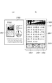
次に、図22と図23を用いて、本実施例における携帯情報端末107の前記アプリケーション画像データ受信時の処理について説明する。図22は、携帯情報端末107がアプリケーション画像データを受信した際のフローチャートである。図23は、本実施例における携帯情報端末107のタッチUI1904の画面表示例である。
Next, the processing at the time of receiving the application image data of the
まず、ステップS2200において、携帯情報端末107は、無線LANモジュール1906を介してMFP100から前記アプリケーション画像データを受信すると、RAM1911に受信したアプリケーション画像データを保存する。
First, in step S 2200, when
次に、ステップS2201において、RAM1911に保存したアプリケーション画像データの構文を解析し、先頭ページと、それに含まれるオブジェクトを読み込む。 Next, in step S2201, the syntax of the application image data stored in the RAM 1911 is analyzed, and the first page and the objects included therein are read.
次に、ステップS2202において、描画部2003は読み込んだ先頭ページに含まれる背景、文字、写真、グラフィックの全てのオブジェクトを、オブジェクトの始点の座標と幅、高さに応じてレンダリングしてタッチUI1904の表示状態を更新する。このとき、先頭ページは、図23のページ2300に示すように、タッチUI1904の幅に合わせて表示倍率が制御される。また、前記表示倍率に縮小したときのページの高さがタッチUI1904よりも小さい場合は、タッチUI1904の中央に表示されるように、タッチUI1904上の座標において、ページ2300の始点が制御される。また、前記表示倍率に縮小したときのページ2300の高さがタッチUI1904よりも大きい場合は、タッチUI1904上の座標において、ページ2300の始点がタッチUI1904の始点(例えば画面の左上)に合うように制御される。このように、タッチUI1904においてページ全体を表示する表示制御方法を、本実施例ではページ表示モードを呼ぶこととする。
In step S2202, the
次に、図23と図24を用いて、本実施例における携帯情報端末107の前記アプリケーション画像データの操作制御に係わるソフトウェアモジュールについて説明する。
Next, software modules related to operation control of the application image data of the
図24は、前記ジェスチャイベント処理部2002において、アプリケーション画像データの操作制御に係わるソフトウェアモジュールの構成を示すブロック図である。
FIG. 24 is a block diagram illustrating a configuration of a software module related to operation control of application image data in the gesture
ジェスチャイベント処理部2002は、ジェスチャイベント発生部2001から、図21に示すジェスチャイベントを受信する。表示変更イベント処理部2400は、ジェスチャイベント処理部2002が受信するジェスチャイベントの内、シングルタップイベント(図21(j))に対する処理を行う。表示変更イベント処理部2400は、シングルタップイベントを受信すると、シングルタップイベントのタッチ座標の座標値が、図23のモード切替ボタン2301、次へボタン2302、前へボタン2303の何れかの上にあるかを判定する。そして、シングルタップイベントのタッチ座標が「モード切替ボタン」2301上である場合は、後述するモード切替処理を行う。また、前記タッチ座標が「次へボタン」2302上である場合は、後述する「次選択処理」(次へボタン選択処理)を行い、前記タッチ座標が「前へボタン」2303上である場合は、後述する「前選択処理」(前へボタン選択処理)を行う。「次選択処理」と「前選択処理」は、表示変更イベント処理部2400内の表示順番制御部2402と表示範囲制御部2403において行われる。
The gesture
スワイプイベント処理部2401は、図21(b)のスワイプイベントに対する処理を行う。ジェスチャイベント処理部2002がスワイプイベントを受信すると、スワイプイベントの移動距離に応じて、タッチUI1904上の座標において、ページ2300の始点を移動させ、その上でタッチUI1904の表示状態を更新する。また、スワイプイベント処理部2401内の移動範囲制限部2404において、後述する移動範囲制限処理を行って、タッチUI1904に表示されるページ2300の移動範囲を制限する。
The swipe
拡大・縮小イベント処理部2405は、図21(c)のピンチインイベントと、図21(d)のピンチアウトイベントに対する処理を行う。ジェスチャイベント処理部2002は、ピンチインイベントやピンチアウトイベントを受信すると、前記二つのイベントの縮小率もしくは拡大率に応じてページ2300の表示倍率を変化させ、その上でタッチUI1904の表示状態を更新する。また、拡大・縮小イベント処理部2405内の縮小時表示モード切替部2406において、後述する縮小時表示モード切替処理を行う。
The enlargement / reduction
オブジェクト選択処理部2407は、図21(i)のダブルタップイベントに対する処理を行う。ジェスチャイベント処理部2002がダブルタップイベントを受信すると、ダブルタップイベントのタッチ座標の座標値を用いて後述するオブジェクト選択処理を行う。なお、前記オブジェクト選択処理は、前記ページ表示モードでのみ動作するようオブジェクト選択イベント処理部2407によって制御される。
The object
次に、図23と図25、図26を用いて、表示変更イベント処理部2400において行われるモード切替処理について説明する。図25は、モード切替処理のフローチャートであり、モード切替ボタン2301がユーザによりタップ指示されるのに応じて実行される。図26は、本実施例における携帯情報端末107のタッチUI1904の画面表示例である。
Next, the mode switching process performed in the display change
まず、ステップS2500において、表示変更イベント処理部2400は、モード切替ボタンが指示された時点で、携帯情報端末107に設定中の表示モードを取得する。表示モードとは、携帯情報端末107がアプリケーション画像データをタッチUI1904に表示する方法を示し、本実施例の携帯情報端末107は、ページ全体を表示するのに適した前記ページ表示モードと、図26に示すようにページ内の一部の領域(すなわちページ画像内の各オブジェクト)を拡大表示するのに適した部分領域表示モードの2つの表示モードを有する。前述した通り、アプリケーション画像データを携帯情報端末107が受信した直後はページ表示モードが設定されている。部分領域表示モードは、図26に示す通り、ページ2300内の各オブジェクトが大きく表示されるようにページ2300の表示倍率と始点を制御する表示モードである。文字オブジェクト2601を拡大表示対象のオブジェクトとして選択したときに表示される画面を図26(b)に示す。なお、図26(a)のオブジェクト2601を囲む破線は、説明をわかり易くするために描いたもので、ページ2300上には存在しない。また、本実施例では、図26(b)に示すように、拡大表示対象のオブジェクト2601の領域が透明で且つそれ以外の領域が半透明グレーである半透明マスク2600を、ページ2300の上に重ねて表示することによって、対象のオブジェクトだけが見やすくなるようにしている。このような半透明マスクを重ねて表示することにより、対象のオブジェクト以外が暗く表示されるので、対象のオブジェクトが強調表示され、ユーザは表示対象になっているオブジェクトの領域を特定しやすくなる。表示変更イベント処理部2400は、モード切替ボタン2301が指示されたときに設定中の表示モードが、部分領域表示モードである場合にはステップS2501に、ページ表示モードである場合にはステップS2504を実行する。
First, in step S2500, the display change
ステップS2501において、表示変更イベント処理部2400は、図26の半透明マスク2600を非表示設定(半透明マスクOFF)にして、ページ表示モードへの切り替えを行う。
In step S2501, the display change
ステップS2502において、表示変更イベント処理部2400は、前述した通り、タッチUI1904の幅に合わせてページ2300の表示倍率を制御すると共に、ページ2300の始点を制御して、ページの表示範囲を決定する。
In step S2502, as described above, the display change
ステップS2503において、表示変更イベント処理部2400は、当該決定されたページの表示範囲に基づいて、タッチUI1904の表示状態を更新する。
In step S2503, the display change
また、モード切替ボタン2301が指示されたときに設定中の表示モードがページ表示モードであった場合には、ステップS2504において、表示変更イベント処理部2400は、表示モードを部分領域表示モードへ切り替え、半透明マスク2600を表示する設定(半透明マスクON)に変更する。
If the display mode being set when the
次に、ステップS2505において、表示変更イベント処理部2400は、ページ2300内の先頭オブジェクトを読み込み、先頭オブジェクトの始点と幅、高さを取得する。ここで、先頭オブジェクトとは、アプリケーション画像データの文書構造ツリーにおいて、最初に読み込まれるオブジェクトである。
Next, in step S2505, the display change
表示変更イベント処理部2400内の表示範囲制御部2403は、ステップS2506において、後述する部分領域表示範囲決定処理を行った後、ステップS2503で、当該決定された表示範囲に基づいてタッチUI1904の表示状態を更新する。なお、S2506の部分領域表示範囲決定処理では、ステップS2505で読み込んだオブジェクトの属性に応じて、ページの表示倍率や始点を制御し、タッチUI1904に表示する部分領域の表示範囲を決定する。部分領域表示範囲決定処理の詳細は後述する。また、このとき表示対象となっているオブジェクトの部分領域以外の領域にはグレーの半透明マスクがかけられるので、ユーザは、表示対象となっているオブジェクトを識別しやすくなる。
In step S2506, the display
次に、表示範囲制御部2403で行われるステップS2506の部分領域表示範囲決定処理の詳細について、図27のフローチャートを用いて説明する。
Next, details of the partial area display range determination processing in step S2506 performed by the display
まず、ステップS2700において、表示範囲制御部2403は、読み込んだオブジェクトの属性を判定する。属性が文字の場合はステップS2701に進み、属性が表である場合はステップS2711に進み、それ以外の属性である場合はステップS2712に進む。
First, in step S2700, the display
ステップS2701において、表示範囲制御部2403は、文字属性である当該表示対象のオブジェクトが、箇条書きであるかを判定する。ここでいう箇条書きのオブジェクトとは、各文字列もしくは行の先頭に点や数字といった行頭文字が存在するオブジェクトを指すものとする。なお、前記行頭文字は、OCR結果から取得することができる。オブジェクトが箇条書きでなく、通常の文字列であった場合にはステップS2702に進み、箇条書きであった場合にはステップS2712に進む。
In step S2701, the display
ステップS2702において、表示範囲制御部2403は、オブジェクトの文字の組み方向を取得する。オブジェクトの組み方向は、前記ステップS304のベクトル化の過程で得られている。
In step S2702, the display
ステップS2703において、表示範囲制御部2403は、文字の組み方向を判定し、組み方向が縦書きである場合にはステップS2704に進み、横書きである場合にはステップS2705に進む。
In step S2703, the display
文字の組み方向が縦書きの場合、ステップS2704において、表示範囲制御部2403は、当該オブジェクトの高さがタッチUI1904の高さに入るようにページの表示倍率を設定する。
If the text composition direction is vertical writing, in step S2704, the display
また、文字の組み方向が横書きの場合、ステップS2705において、表示範囲制御部2403は、当該オブジェクトの幅がタッチUI1904の幅に入るようにページの表示倍率を設定する。
When the text composition direction is horizontal writing, in step S2705, the display
次に、ステップS2706において、ステップS2704またはステップS2705で設定した表示倍率に拡縮したオブジェクトの全体がタッチUI1904に表示できるかを判断する。オブジェクト全体がタッチUI1904よりも大きく、全体を表示できない場合にはステップS2707に進み、一方、オブジェクト全体がタッチUI1904よりも小さく、全体を表示できる場合にはステップS2710に進む。
Next, in step S2706, it is determined whether the entire object scaled to the display magnification set in step S2704 or step S2705 can be displayed on the
ステップS2707において当該オブジェクトにおける文字の組み方向を判定し、縦書きであると判定した場合はステップS2708に進み、横書きであると判定した場合はステップS2709に進む。 In step S2707, the text composition direction of the object is determined. If it is determined that the writing is vertical, the process proceeds to step S2708. If it is determined that the writing is horizontal, the process proceeds to step S2709.
ステップS2708において、表示範囲制御部2403は、オブジェクト全体がタッチUI1904に表示できない縦書きの文字領域を表示するので、当該オブジェクトの右上端がタッチUI1904の右上端に合うように、前記ページ2300の始点位置を設定する。すなわち、縦書きの場合の先頭行が表示されるように表示位置を設定する。
In step S <b> 2708, the display
ステップS2709において、表示範囲制御部2403は、オブジェクト全体がタッチUI1904に表示できない横書きの文字領域を表示するので、当該オブジェクトの左上端がタッチUI1904の左上端に合うように、前記ページ2300の始点を設定する。すなわち、横書きの場合の先頭行が表示されるように表示位置を設定する。
In step S <b> 2709, the display
また、ステップS2710において、オブジェクト全体がタッチUI1904の画面内に収まるので、表示範囲制御部2403は、当該オブジェクトの中央がタッチUI1904の中央に合うようにページ2300の始点を設定する。
In step S2710, since the entire object is within the screen of the
なお、ステップS2700でオブジェクトの属性が表であると判定した場合には、ステップS2711において、表示範囲制御部2403は、表のヘッダ位置を検出する。ヘッダの位置は、例えば、先頭行(一番上の行)と先頭列(一番左の列)の文字のフォント種がボールドであるか否か、ベクトル化した際のベクトルデータの近似曲線の太さ、表罫線の太さ、表の各セルの背景色などによって判断することができる。ステップS2711で検出した表のヘッダ位置が先頭行である場合には、ステップS2703からステップS2705に進む。また、表のヘッダ位置が先頭列である場合には、ステップS2703からステップS2704に進む。また、ステップS2707では、表のヘッダは一番上の行か一番左の列に存在することが一般的であるため、ステップS2709に進み、オブジェクトの左上端がタッチUIの左上端に合うようにページの始点を設定する。このようにすることで、表のヘッダが表示されるように表示位置が設定されることになる。
If it is determined in step S2700 that the object attribute is a table, in step S2711, the display
また、ステップS2700でオブジェクトの属性がその他の属性(文字・表以外の属性)と判定された場合、もしくは、ステップS2701で箇条書きであると判断された場合、ステップS2712において、表示範囲制御部2403は、当該オブジェクト全体がタッチUI1904に入るように、ページの表示倍率を設定する。そして、ステップS2710において、オブジェクトの中央がタッチUI1904の中央に合うようにページ2300の始点を設定する。
If it is determined in step S2700 that the attribute of the object is another attribute (attribute other than characters / tables), or if it is determined in step S2701 that the item is a bullet, the display
「次へボタン」2302がユーザによりタップ(指定)されたときに実行される「次選択処理(次へボタン選択処理)」について、図28のフローチャートを用いて説明する。 The “next selection process (next button selection process)” executed when the “next button” 2302 is tapped (designated) by the user will be described with reference to the flowchart of FIG.
ステップS2800において、表示変更イベント処理部2400は、「次へボタン」2302がタップされたときに携帯情報端末107に設定されている表示モードを取得する。取得した表示モードが部分領域表示モードである場合には、ステップS2801に進み、ページ表示モードである場合にはステップS2805に進む。
In step S2800, the display change
ステップS2801において、表示順番制御部2402は、現在読み込んでいるページの全オブジェクトから、文書構造ツリーに基づいて次に表示すべきオブジェクトを選択し、そのオブジェクトを読み込む。本実施例において、文書ツリー構造上の表示順番は、文書ツリー構造において、先頭の上位階層のオブジェクト、そのオブジェクトの下位階層に属するオブジェクトの順で、更に、その下位階層のオブジェクトの表示が全て終わった後、次の上位階層のオブジェクト、その下位階層のオブジェクト、というような順番であるとする。例えば、図17において、V0はページを表し、最初に読み込まれるオブジェクトはH1である。H1のオブジェクトが部分領域表示モードでタッチUI1904に表示されている状態で、「次選択処理」が行われると、H1は下位階層を持つため、T1のオブジェクトが読み込まれる。さらに、T1のオブジェクトが表示されている状態で「次選択処理」が行われると、T1は下位階層を持たず、同階層にT2が存在するため、T2が読み込まれる。T2のオブジェクトが表示されている状態で「次選択処理」が行われると、T2は下位階層を持たず、同階層に次のオブジェクトは存在しないため、次の上位階層のS1が読み込まれる。なお、本実施例において、描画要素を持たないH1を選択して読み込むとしているが、描画要素を持つT1やT2だけを選択するようにしても良いことは言うまでもない。また、例えば、文字属性のオブジェクトのみなど、特定の属性を持つオブジェクトのみを選択したり、特定の属性のみを除外して選択することも可能である。
In step S2801, the display
ステップS2802において、表示順番制御部2402は、ステップS2801で次のオブジェクトを読み込めたか否かを判定する。ステップS2801で次のオブジェクトが読み込めた場合(選択可能なオブジェクトがあった場合)は、当該読み込んだオブジェクトを処理対象としてステップS2506に進む。なお、ステップS2506の部分領域表示範囲決定処理は図27と同様であるため、ここでの説明は省く。そして、ステップS2803において、当該読み込まれたオブジェクトの属性および始点と幅、高さに基づいて制御されたページの表示倍率と始点を用いて、タッチUI1904の表示状態を更新する。
In step S2802, the display
一方、ステップS2801で次のオブジェクトが読み込めなかった場合(次に選択可能なオブジェクトが無かった場合)は、既にページ内の最終オブジェクトが読み込まれている状態であり、ステップS2802で全てのオブジェクトの表示処理が終了したと判断し、ステップS2804に進む。ステップS2804において、表示順番制御部2402は、部分領域表示モードを終了して半透明マスク2600を非表示にして、ページ表示モードへと切り替える。
On the other hand, if the next object cannot be read in step S2801 (there is no next selectable object), the last object in the page has already been read, and all objects are displayed in step S2802. It is determined that the process has ended, and the process proceeds to step S2804. In step S2804, the display
ステップS2805において、表示モードがページ表示モードであるので、RAM1911に保存したアプリケーション画像データの構文を解析し、次のページと、それに含まれるオブジェクトを読み込む。 In step S2805, since the display mode is the page display mode, the syntax of the application image data stored in the RAM 1911 is analyzed, and the next page and objects included in the page are read.
ステップS2806において、表示順番制御部2402は、ステップS2805で次のページが読み込めた場合はステップS2807に進む。一方、既にRAM1911に保存したアプリケーション画像データの最終ページが読み込まれている状態であり、S2805で次に読み込み可能なページが無かった場合は、ステップS2808に進む。ステップS2808では、RAM1911に保存したアプリケーション画像データの構文を解析し、先頭ページと、それに含まれるオブジェクトを読み込む。
In step S2806, if the next page can be read in step S2805, the display
次に、ステップS2807において、表示範囲制御部2403は、前述した通り、タッチUI1904の幅に合わせてページの表示倍率を制御すると共に、ページの始点を制御して、ページの表示範囲を決定し、ステップS2803では、当該決定されたページ表示範囲に基づいてタッチUI1904の表示状態を更新する。
Next, in step S2807, as described above, the display
次に、「前へボタン」2302がユーザによりタップ(指定)されたときに実行される「前選択処理(前へボタン選択処理)」について、図29のフローチャートを用いて説明する。 Next, the “previous selection process (previous button selection process)” executed when the “previous button” 2302 is tapped (designated) by the user will be described with reference to the flowchart of FIG.
前選択処理は、前記次選択処理とほぼ同じ構成であるため、ここでは異なるステップS2900とステップS2901、ステップS2902についてのみ説明する。 Since the pre-selection process has substantially the same configuration as the next selection process, only different steps S2900, S2901, and S2902 will be described here.
ステップS2900において、表示順番制御部2402は、現在読み込んでいるページの全オブジェクトから、文書構造ツリーに基づいて次に表示すべきオブジェクトを選択し、そのオブジェクトを読み込む。本実施例において、「前へボタン」が指定されたときの文書ツリー構造上の表示順番は、文書ツリー構造において末尾の下位階層のオブジェクト、そのオブジェクトの上位階層のオブジェクトというように、下位階層から上位階層への順番であるとする。すなわち、下位階層のオブジェクトの表示が全て終わった後、その上位階層における他のオブジェクトの表示へと移るのもとする。例えば、図17において、最初に読み込まれるオブジェクトは末尾の下位階層オブジェクトであるT7である。部分領域表示モードで、T7のオブジェクトがタッチUI1904に表示されている状態で、「前選択処理」が行われると、同じ階層にT6が存在するため、T6のオブジェクトが読み込まれる。さらに、T6のオブジェクトが表示されている状態で「前選択処理」が行われると、同じ階層にその他のオブジェクトが存在しないため、その上位階層であるV2が読み込まれる。V2のオブジェクトが表示されている状態で「前選択処理」が行われると、V2は同じ階層にV1を持ち、更にV1は下位階層にオブジェクトを持つため、V1の下位階層の末尾にあるT5のオブジェクトが読み込まれる。なお、「前選択処理」においても、「次選択処理」と同様に、描画要素を持つオブジェクトだけを選択するようにしても良く、また、特定の属性を持つオブジェクトのみを選択したり、特定の属性のみを除外して選択することも可能である。
In step S2900, the display
次に、移動範囲制限部2404で行われる移動範囲制限処理について、図30のフローチャートを用いて説明する。
Next, the movement range restriction process performed by the movement
ステップS3000において、移動範囲制限部2404は、スワイプ操作が行われたときの携帯情報端末107に設定されている表示モードを取得して、部分領域表示モードであるか判定する。表示モードが部分領域表示モードである場合にはステップS3001に進み、ページ表示モードである場合には何も行わずに処理を終了する。
In step S3000, the movement
ステップS3000で表示モードが部分領域表示モードであると判定した場合には、ステップS3001において、移動範囲制限部2404は、現在のページの表示倍率で表示したときの現在読み込まれているオブジェクトの幅が、タッチUI1904の画面の幅より大きいか否かを判定する。このとき、前記オブジェクトの幅がタッチUIの画面幅よりも大きい場合には、ステップS3002に進み、そうでない場合には、ステップS3004に進む。
If it is determined in step S3000 that the display mode is the partial area display mode, in step S3001, the movement
ステップS3002において、スワイプイベント処理部2401がスワイプイベントの移動距離に応じてオブジェクトを含むページの表示位置を移動した際に、移動範囲制限部2404は、オブジェクトの左端または右端がタッチUI1904の画面内に移動したかを判定する。その結果、オブジェクトの左端または右端がタッチUIの画面内にあると判定した場合には、ステップS3003に進み、そうでない場合には、ステップS3006に進む。
In step S3002, when the swipe
ステップS3003において、移動範囲制限部2404は、画面内に移動された該オブジェクトの左端または右端をタッチUIの画面の端に移動させて、できるだけ該オブジェクトが表示されるように、ページの始点のx座標を補正する。
In step S3003, the movement
また、ステップS3001でオブジェクトの幅がタッチUIの画面幅よりも大きくない場合には、ステップS3004において、スワイプイベントの移動距離に応じてオブジェクトを含むページの表示位置を移動した際に、移動範囲制限部2404は、オブジェクトの左端または右端がタッチUIの画面外に移動したかを判定する。その結果、オブジェクトの左端または右端がタッチUIの画面外にあると判定した場合には、ステップS3005に進み、そうでない場合には、ステップS3006に進む。
If the object width is not larger than the screen width of the touch UI in step S3001, the movement range is limited when the display position of the page including the object is moved in accordance with the movement distance of the swipe event in step S3004. The
ステップS3005において、移動範囲制限部2404は、当該オブジェクトの左端または右端を画面の端に移動させて、該オブジェクトの全体が表示されるようにページの始点のx座標を補正する。
In step S3005, the movement
ステップS3006において、移動範囲制限部2404は、現在のページの表示倍率で表示したときの現在読み込まれているオブジェクトの高さが、タッチUI1904の画面の高さより大きいか否かを判定する。このとき、前記オブジェクトの高さがタッチUIの画面高さよりも大きい場合には、ステップS3007に進み、そうでない場合には、ステップS3009に進む。
In step S3006, the movement
ステップS3007において、移動範囲制限部2404は、スワイプイベントの移動距離に応じてオブジェクトを含むページの表示位置を移動した際に、オブジェクトの上端または下端がタッチUI1904の画面内に移動したかを判定する。その結果、オブジェクトの上端または下端がタッチUIの画面内にあると判定した場合には、ステップS3008に進み、そうでない場合には、ステップS3011に進む。
In step S3007, the movement
ステップS3008において、移動範囲制限部2404は、画面内に移動されたオブジェクトの上端または下端を画面の端に移動させて、できるだけ該オブジェクトが表示されるようにページの始点のy座標を補正する。
In step S3008, the movement
ステップS3006でオブジェクトの高さがタッチUIの画面高さよりも大きくない場合には、ステップS3009において、移動範囲制限部2404は、スワイプイベントの移動距離に応じてオブジェクトを含むページの表示位置を移動した際に、オブジェクトの上端または下端がタッチUIの画面外に移動したかを判定する。オブジェクトの上端または下端がタッチUIの画面外に移動したと判定した場合には、ステップS3010に進み、そうでない場合には、ステップS3011に進む。
If the object height is not larger than the screen height of the touch UI in step S3006, in step S3009, the movement
ステップS3010において、移動範囲制限部2404は、当該オブジェクトの上端または下端を画面内に移動させて、該オブジェクトの全体が表示されるようにページの始点のy座標を補正する。
In step S3010, the movement
最後に、ステップS3011において、表示変更イベント処理部2400は、ページの表示倍率と始点に応じてタッチUI1904の表示状態を更新する。
Finally, in step S3011, the display change
このように、オブジェクトの移動範囲を制限することで、ユーザは、オブジェクトの端部を容易に識別することができる。 Thus, by limiting the movement range of the object, the user can easily identify the end of the object.
次に、ピンチイン操作がおこなわれときに、縮小時表示モード切替部2406で行われる縮小時表示モード切替処理について、図31のフローチャートを用いて説明する。
Next, reduction-time display mode switching processing performed by the reduction-time display
ステップS3100において、縮小時表示モード切替部2406は、ユーザにより操作が行われたときの携帯情報端末107に設定されている表示モードを取得する。取得した表示モードが部分領域表示モードである場合にはステップS3101に進み、ページ表示モードである場合には何も行わすに処理を終了する。
In step S3100, the reduced display
ステップS3101において、縮小時表示モード切替部2406は、現在のページの表示倍率で表示したときの現在読み込まれているオブジェクトの幅が、タッチUI1904の画面の幅より小さいか否かを判定する。オブジェクトの幅がタッチUIの画面幅よりも小さい場合には、ステップS3102に進み、そうでない場合には何も行わずに処理を終了する。
In step S <b> 3101, the reduction-time display
ステップS3102において、縮小時表示モード切替部2406は、現在のページの表示倍率で表示したときの現在読み込まれているオブジェクトの高さが、タッチUI1904の画面の高さより小さいか否かを判定する。このとき、前記オブジェクトの高さがタッチUIの画面高さよりも小さい場合には、ステップS3103に進み、そうでない場合には何も行わずに処理を終了する。
In step S <b> 3102, the reduction display
ステップS3103において、該オブジェクトを含むページの表示倍率がさらに縮小されようとしているのかを判断する。すなわち、縮小時表示モード切替部2406が受信したイベントがピンチインイベントであるか否かを判定する。ここで、ページがさらに縮小されようとしていると判断した場合には、ステップS3104に進み、そうでない場合には何も行わずに処理を終了する。
In step S3103, it is determined whether the display magnification of the page including the object is to be further reduced. That is, it is determined whether or not the event received by the reduced display
ステップS3104において、縮小時表示モード切替部2406は、半透明マスク2600を非表示にして、携帯情報端末107の表示モードを部分領域表示モードからページ表示モードに切り替える。
In step S3104, the reduced display
最後に、ステップS3105において、表示変更イベント処理部2400は、該ピンチインイベントに基づいて決定されるページの表示倍率と始点に応じてタッチUI1904の表示状態を更新する。
Finally, in step S3105, the display change
次に、ダブルタップ操作が行われたときに、オブジェクト選択処理部2407で行われるオブジェクト選択処理について、図32のフローチャートを用いて説明する。
Next, object selection processing performed by the object
まず、ステップS3200において、オブジェクト選択処理部2407は、ユーザにより操作が行われたときの携帯情報端末107に設定されている表示モードを取得する。取得した表示モードがページ表示モードである場合にはステップS3201に進み、部分領域表示モードである場合には何も行わすに処理を終了する。
First, in step S3200, the object
ステップS3201において、オブジェクト選択処理部2407は、受信したダブルタップイベントのタッチ座標の座標値を取得する。前記タッチ座標の座標値はタッチUI1904上の座標値であるため、タッチUIに表示しているページの表示倍率と始点に基づいて、ページにおける座標値に換算する。
In step S3201, the object
ステップS3202において、タッチUIに表示している現在のページ内の全オブジェクトの中から先頭オブジェクトの情報を読み込む。 In step S3202, information on the first object is read from all objects in the current page displayed on the touch UI.
ステップS3203において、ステップS3201で求めたページにおける座標値が、読み込んだオブジェクトの領域情報内に含まれるか否かを判定する。前記ページにおける座標値が当該読み込んだオブジェクトの領域情報内にある場合には、ステップS3204に進み、そうでない場合にはステップS3206に進む。 In step S3203, it is determined whether or not the coordinate value on the page obtained in step S3201 is included in the area information of the read object. If the coordinate value on the page is in the area information of the read object, the process proceeds to step S3204; otherwise, the process proceeds to step S3206.
ステップS3204において、携帯情報端末107の表示モードをページ表示モードから部分領域表示モードに切り替える。同時に、非表示であった半透明マスク2600を表示することで、当該ダブルタップされたオブジェクト以外の領域に半透明マスクがかかるように制御し、ステップS2506に進む。
In step S3204, the display mode of
ステップS2506において、ステップS3202またはステップS3206で読み込んだオブジェクト(すなわち、当該ダブルタップされたオブジェクト)の部分領域表示範囲決定処理を行う。部分領域表示範囲決定処理については前述した通りであるので、ここでの詳細な説明は省く。 In step S2506, partial area display range determination processing of the object read in step S3202 or step S3206 (that is, the double-tapped object) is performed. Since the partial region display range determination process is as described above, a detailed description thereof is omitted here.
そして、ステップS3205において、表示変更イベント処理部2400は、部分領域表示範囲決定処理で決定したページの表示倍率と始点に応じてタッチUI1904の表示状態を更新する。
In step S3205, the display change
また一方、ステップS3206において、オブジェクト選択処理部2407は、現在のページ内の全オブジェクトの中から、現在読み込んでいるオブジェクトの次のオブジェクトの情報を読み込む。
On the other hand, in step S3206, the object
ステップS3207において、オブジェクト選択処理部2407は、ステップS3206で次のオブジェクトが読み込めたか否かを判定し、読み込めた場合にはステップS3203に戻り、読み込めなかった場合には何もせずに処理を終了する。
In step S3207, the object
なお、本実施例において、現在タッチUIに表示しているページ内の全オブジェクトを対象に、前記ページにおける座標値がオブジェクトの領域情報内にあるか否かを判定しているが、それに限るものではない。例えば、前記前選択処理や後選択処理と同様に、描画要素を持たないオブジェクトを無視し、描画要素を持つオブジェクトだけを選択するようにしても良い。また、例えば、文字属性のオブジェクトのみなど、特定の属性を持つオブジェクトのみを選択したり、特定の属性のみを除外して選択することも可能である。 In this embodiment, for all objects in the page currently displayed on the touch UI, it is determined whether or not the coordinate value in the page is in the area information of the object. is not. For example, as in the pre-selection process and the post-selection process, an object having no drawing element may be ignored and only an object having a drawing element may be selected. Further, for example, it is possible to select only an object having a specific attribute such as only an object having a character attribute, or to exclude and select only a specific attribute.
次に、図26と図33、図34を用いて、本実施例における部分領域表示モードの表示を具体的に説明する。図33と図34は、本実施例における携帯情報端末107のタッチUI1904の画面表示例である。
Next, the display of the partial area display mode in the present embodiment will be specifically described with reference to FIGS. 26, 33, and 34. 33 and 34 are screen display examples of the
図26において、オブジェクト2601は横書きの文字の属性を持つオブジェクトである。オブジェクト2601は、図26(a)のように破線で示す領域情報を持つ。オブジェクト2601の属性は文字であるため、オブジェクト2601が読み込まれた直後は、前記部分領域表示範囲決定処理において、オブジェクトの幅がタッチUI1904の画面幅に入る倍率に、ページの表示倍率が設定される。オブジェクト2601の場合、当該設定されたページの表示倍率において、オブジェクトの高さも、タッチUI1904の画面の高さより小さくなるため、該オブジェクトの中心がタッチUI1904の中心に合うように、ページの始点が設定され、図26(b)に示すように表示される。
In FIG. 26, an
また、図33において、オブジェクト3300は縦書きの文字の属性を持つオブジェクトである。オブジェクト3300は、図33(a)のように破線で示す領域情報を持つ。オブジェクト3300の属性は文字であるため、オブジェクト3300が読み込まれた直後は、前記部分領域表示範囲決定処理において、オブジェクトの高さがタッチUI1904の画面高さに入る倍率に、ページの表示倍率が設定される。また、オブジェクト3300の場合、当該設定されたページの表示倍率において、オブジェクトの幅が、タッチUI1904の画面の幅よりも大きくなるため、オブジェクト右上端がタッチUI1904の右上端に合うように、ページの始点が設定され、図33(b)に示すように表示される。
In FIG. 33, an
また、図34において、オブジェクト3400は図面の属性を持つオブジェクトである。オブジェクト3400は、図34(a)のように破線で示す領域情報を持つ。オブジェクト3400の属性は図面であるため、オブジェクト3400が読み込まれた直後は、前記部分領域表示範囲決定処理において、オブジェクトの幅と高さがタッチUI1904の画面幅と高さに入る倍率に、ページの表示倍率が設定される。また、オブジェクト中心がタッチUI1904の中心に合うように、ページの始点が設定され、図34(b)に示すように表示される。
In FIG. 34, an
次に、図34と図35、図36を用いて、本実施例における前記移動範囲制限処理の制限例を具体的に説明する。図35と図36は、本実施例における携帯情報端末107のタッチUI1904の画面表示例である。
Next, a restriction example of the movement range restriction process in the present embodiment will be specifically described with reference to FIGS. FIG. 35 and FIG. 36 are screen display examples of the
図35(a)は、オブジェクト3400をタッチUI1904に表示した一例である。図35(a)では、オブジェクト3400の幅と高さがタッチUI1904の画面幅と高さよりも小さく、オブジェクト3400がタッチUIの画面内に全て収まるように表示されている。図35(b)は、ユーザの指が3500から3501の方向(すなわち左方向)にスワイプ動作されたときの表示例である。スワイプイベント処理部2401は、スワイプイベントを受信するたびに移動距離だけページの始点を動かしてタッチUI1904の表示を更新する。図35(b)では、ユーザのスワイプ動作によって、オブジェクト3400の左端がタッチUI1904の画面外に移動してしまっている。図35(c)は、スワイプイベント処理部2401によって図35(b)のように左端が画面外に移動されたオブジェクト3400を、前記移動範囲制限処理によって画面内に戻して表示されるようにページの始点を補正した場合の表示例である。すなわち、オブジェクト3400は、表示中のオブジェクトの幅と高さがタッチUIの画面幅と高さよりも小さいため、オブジェクト3400が画面外に移動すると、移動範囲制限処理によって、画面内に表示されるようにページの始点が補正される。
FIG. 35A shows an example in which the
図36(a)は、オブジェクト3400をピンチアウト動作によって拡大してタッチUI1904に表示した一例である。図36(a)は、表示中のオブジェクト3400の幅がタッチUI1904の画面幅よりも大きく、オブジェクト3400の左右端がタッチUIの画面外に、上下端が画面内に表示されている。図36(b)は、ユーザの指が3600から3601の方向(すなわち左方向)にスワイプ動作されたときの表示例である。スワイプイベント処理部2401は、スワイプイベントを受信するたびに移動距離だけページの始点を動かしてタッチUI1904の表示を更新する。図36(b)では、ユーザのスワイプ動作によって、オブジェクト3400の右端がタッチUI1904の画面内に移動している。図36(c)は、スワイプイベント処理部2401によって右端が画面の内側に移動されたオブジェクト3400を、前記移動範囲制限処理によって、当該オブジェクト3400の右端がタッチUIの画面の右端にほぼ合うようにページの始点を補正した場合の表示例である。すなわち、オブジェクト3400は、表示中のオブジェクトの幅がタッチUIの画面幅よりも大きいため、オブジェクト3400の端が画面内に移動された場合、移動範囲制限処理によって、当該オブジェクトができるだけ表示されるように、当該オブジェクトの端が画面の端に合うようにページの始点が補正される。
FIG. 36A shows an example in which the
なお、本実施例において、MFP100は携帯情報端末107に表示用のアプリケーション画像データを送付し、携帯情報端末107は受信したアプリケーション画像データを表示する構成としている。しかしながら、例えば、MFP100において、アプリケーション画像データを内部に保持する携帯情報端末107で実行可能なアプリケーションを生成し、携帯情報端末107に配信するような構成にしても良いことは言うまでもない。なお、そのときの携帯情報端末107で実行可能なアプリケーションは、本実施例で説明したソフトウェアモジュールであるジェスチャイベント処理部2002を内部に持って、アプリケーション画像データを制御する。
In this embodiment, the
また、MFP100は、生成したアプリケーション画像データを文書管理サーバ106に送信すると共に、携帯情報端末107にそのアプリケーション画像データの場所を示すアドレスを送付するようにしても良い。この場合、携帯情報端末107はアプリケーション画像データの実体データは持たず、LAN102を通して、文書管理サーバ106のデータが保持されるデータベース105から随時ページやオブジェクトの情報を取得・表示する。
The
以上説明したように、本実施例によれば、ページ内を、スワイプやピンチ動作によって自由にスクロール・拡大縮小して閲覧できると共に、部分領域表示モードでは、任意のオブジェクトのみを内容に応じて見やすい形で画面に表示することができる。さらに、ユーザは「次へボタン」や「前へボタン」を操作するだけで、ページ内の適切な範囲を適切な順序で次々に表示することで、微妙な調整の手間をかけること無くページ内の情報を読み進めることができる。また、部分領域表示モードにおいては、スワイプ動作でオブジェクトを移動させる際、当該オブジェクトの端部位置に基づいて当該オブジェクトの移動範囲を制限するので、ユーザは当該オブジェクトの範囲がどこまでなのかを容易に理解することができる。よって、ユーザは当該表示中のオブジェクトとその他のオブジェクトとを明確に区別することができる。 As described above, according to the present embodiment, the inside of a page can be freely scrolled / enlarged / reduced by a swipe or a pinch operation, and only an arbitrary object can be easily viewed according to the contents in the partial area display mode. Can be displayed on the screen. In addition, the user simply operates the “Next button” and “Previous button” to display the appropriate range within the page one after another in the appropriate order, so that there is no need for subtle adjustments. Can read the information. In the partial area display mode, when the object is moved by a swipe operation, the range of movement of the object is limited based on the end position of the object, so that the user can easily determine how far the range of the object is. I can understand. Therefore, the user can clearly distinguish the displayed object from other objects.
[実施例2]
本実施例2では、前記移動範囲制限部2404において、オブジェクトの移動範囲を制限するとき、一度は移動範囲を制限するが、当該制限した後に移動範囲の制限を解除状態にする。したがってその後、さらにユーザによって範囲外への移動が再度指示された場合には移動可能になる。
[Example 2]
In the second embodiment, when the movement
なお、前述した第一の実施例とは、図30の移動範囲制限処理の一部が異なるのみであるため、前述の実施例と同様の部分に関しては、同一番号を付けて省略し、異なる部分のみを以下に説明する。 30 is different from the first embodiment described above only in part of the movement range restriction process in FIG. 30. Therefore, the same parts as those of the above-described embodiment are denoted by the same reference numerals and omitted. Only this will be described below.
図37は、実施例2の移動範囲制限部2404で行われる移動範囲制限処理のフローチャートであり、実施例1(図30)の移動範囲制限処理とは、横制限解除フラグと縦制限解除フラグを用いる部分が異なる。なお、横制限解除フラグと、縦制限解除フラグは、ページ及びオブジェクトの読み込みが行われる際に必ずFALSEに初期化される。
FIG. 37 is a flowchart of the movement range restriction process performed by the movement
ステップS3001で表示中のオブジェクトの幅が画面の幅より大きいと判断され、更に、ステップS3002でオブジェクトの左端または右端がタッチUIの画面内に移動されたと判断した場合、ステップS3700に進む。ステップS3700において、移動範囲制限部2404は、横制限解除フラグの状態を確認する。横制限解除フラグがTRUEである場合には、移動範囲の制限は行わず、ステップS3006に進む。また、横制限解除フラグがFALSEである場合には、ステップS3003に進み、オブジェクトの移動範囲を一旦制限した後、ステップS3701において横制限解除フラグをTRUEにしてステップS3006に進む。また、ステップS3002でオブジェクトの左端または右端がタッチUIの画面内に移動されていないと判断した場合には、ステップS3702に進み、横制限解除フラグをFALSEにしてステップS3006に進む。
If it is determined in step S3001 that the width of the object being displayed is greater than the width of the screen, and if it is determined in step S3002 that the left end or right end of the object has been moved within the touch UI screen, the process advances to step S3700. In step S3700, the movement
また、ステップS3001で表示中のオブジェクトの幅が画面の幅より小さいと判断され、更に、ステップS3004でオブジェクトの左端または右端がタッチUIの画面外に移動されたと判断した場合、ステップS3703に進む。ステップS3703において、移動範囲制限部2404は、横制限解除フラグの状態を確認する。横制限解除フラグがTRUEである場合には、移動範囲の制限は行わず、ステップS3006に進む。また、横制限解除フラグがFALSEである場合には、ステップS3005に進み、オブジェクトの移動範囲を一旦制限した後、ステップS3704において横制限解除フラグをTRUEにしてステップS3006に進む。また、ステップS3004でオブジェクトの左端または右端がタッチUIの画面外に移動されていないと判断した場合には、ステップS3705に進み、横制限解除フラグをFALSEにしてステップS3006に進む。
If it is determined in step S3001 that the width of the object being displayed is smaller than the screen width, and if it is determined in step S3004 that the left end or right end of the object has been moved outside the touch UI screen, the process advances to step S3703. In step S3703, the movement
ステップS3006で表示中のオブジェクトの高さが画面の高さより大きいと判断され、更に、ステップS3007でオブジェクトの上端または下端がタッチUIの画面内に移動されたと判断した場合、ステップS3706に進む。ステップS3706において、移動範囲制限部2404は、縦制限解除フラグの状態を確認する。縦制限解除フラグがTRUEである場合には、移動範囲の制限は行わず、ステップS3011に進む。また、縦制限解除フラグがFALSEである場合には、ステップS3008に進み、オブジェクトの移動範囲を一旦制限した後、ステップS3707において縦制限解除フラグをTRUEにしてステップS3011に進む。また、ステップS3007でオブジェクトの上端または下端がタッチUIの画面内に移動されていないと判断した場合、ステップS3708に進み、縦制限解除フラグをFALSEにしてステップS3011に進む。
If it is determined in step S3006 that the height of the object being displayed is larger than the height of the screen, and if it is determined in step S3007 that the upper end or lower end of the object has been moved into the touch UI screen, the process advances to step S3706. In step S3706, the movement
また、ステップS3006で表示中のオブジェクトの高さが画面の高さより小さいと判断され、更に、ステップS3009でオブジェクトの上端または下端がタッチUIの画面外に移動されたと判断した場合、ステップS3709に進む。ステップS3709において、移動範囲制限部2404は、縦制限解除フラグの状態を確認する。縦制限解除フラグがTRUEである場合には、移動範囲の制限は行わず、ステップS3011に進む。また、縦制限解除フラグがFALSEである場合には、ステップS3010に進み、オブジェクトの移動範囲を一旦制限した後、ステップS3710において縦制限解除フラグをTRUEにしてステップS3011に進む。また、ステップS3009でオブジェクトの上端または下端がタッチUIの画面外に移動されていないと判断した場合、ステップS3711に進み、縦制限解除フラグをFALSEにしてステップS3011に進む。
If it is determined in step S3006 that the height of the object being displayed is smaller than the height of the screen, and if it is determined in step S3009 that the upper end or lower end of the object has been moved outside the touch UI screen, the process advances to step S3709. . In step S3709, the movement
以上説明したように、本実施例によれば、ページ内を、スワイプやピンチ動作によって自由にスクロール・拡大縮小して閲覧できると共に、部分領域表示モードでは、任意のオブジェクトのみを内容に応じて見やすい形で画面に表示することができる。さらに、ユーザは「次へボタン」や「前へボタン」を操作するだけで、ページ内の適切な範囲を適切な順序で次々に表示することで、微妙な調整の手間をかけること無くページ内の情報を読み進めることができる。また、部分領域表示モードにおいては、スワイプ動作でオブジェクトを移動させる際、当該オブジェクトの端部位置に基づいて当該オブジェクトの移動範囲を一旦制限するので、ユーザは当該オブジェクトの範囲がどこまでなのかを容易に理解することができる。更に、一旦制限された後に、再度移動指示された場合は、移動させることもできる。 As described above, according to the present embodiment, the inside of a page can be freely scrolled / enlarged / reduced by a swipe or a pinch operation, and only an arbitrary object can be easily viewed according to the contents in the partial area display mode. Can be displayed on the screen. In addition, the user simply operates the “Next button” and “Previous button” to display the appropriate range within the page one after another in the appropriate order, so that there is no need for subtle adjustments. Can read the information. In the partial area display mode, when the object is moved by a swipe operation, the range of movement of the object is temporarily limited based on the end position of the object, so that the user can easily determine how far the range of the object is. Can understand. Further, if the movement is instructed again after being restricted once, it can be moved.
[その他の実施例]
本発明は、複数の機器(例えばホストコンピュータ、インターフェース機器、リーダ、プリンタなど)から構成されるシステムに適用しても、一つの機器からなる装置(例えば、複写機、ファクシミリ装置など)に適用してもよい。また本発明の目的は、前述の実施例の機能を実現するプログラムコードを記録した記録媒体を、システムあるいは装置に供給し、そのシステムあるいは装置のコンピュータが記憶媒体に格納されたプログラムコードを読み出し実行することによっても達成される。この場合、記憶媒体から読み出されたプログラムコード自体が前述した実施例の機能を実現することになり、そのプログラムコード自体およびプログラムコードを記憶した記憶媒体は本発明を構成することになる。
[Other Examples]
The present invention can be applied to a system composed of a plurality of devices (for example, a host computer, an interface device, a reader, a printer, etc.) or an apparatus composed of a single device (for example, a copier, a facsimile machine, etc.). May be. Another object of the present invention is to supply a recording medium recording a program code for realizing the functions of the above-described embodiments to a system or apparatus, and the computer of the system or apparatus reads and executes the program code stored in the storage medium. Is also achieved. In this case, the program code itself read from the storage medium realizes the functions of the above-described embodiments, and the program code itself and the storage medium storing the program code constitute the present invention.
また、本発明には、プログラムコードの指示に基づき、コンピュータ上で稼働しているオペレーティングシステム(OS)などが実際の処理の一部または全部を行い、その処理によって前述した実施例の機能が実現される場合も含まれる。さらに、記憶媒体から読み出されたプログラムコードが、コンピュータに挿入された機能拡張カードやコンピュータに接続された機能拡張ユニットに備わるメモリに書込まれた場合についても、本発明は適用される。その場合、書き込まれたプログラムコードの指示に基づき、その機能拡張カードや機能拡張ユニットに備わるCPUなどが実際の処理の一部または全部を行い、その処理によって前述した実施例の機能が実現される。 Further, according to the present invention, the operating system (OS) running on the computer performs part or all of the actual processing based on the instruction of the program code, and the functions of the above-described embodiments are realized by the processing. This is also included. Furthermore, the present invention is also applied to the case where the program code read from the storage medium is written into a memory provided in a function expansion card inserted into the computer or a function expansion unit connected to the computer. In that case, based on the instruction of the written program code, the CPU of the function expansion card or function expansion unit performs part or all of the actual processing, and the functions of the above-described embodiments are realized by the processing. .
また、上述した実施形態では、コンピュータがプログラムを実行することにより、各処理部として機能するものとしたが、処理の一部または全部を専用の電子回路(ハードウェア)で構成するようにしても構わない。 In the above-described embodiment, the computer functions as each processing unit by executing a program. However, part or all of the processing may be configured by a dedicated electronic circuit (hardware). I do not care.
Claims (16)
前記画像に含まれる各オブジェクトを表示する第1の表示モードが指定された場合、表示対象のオブジェクトの属性に応じて、表示倍率と表示位置とを設定する設定手段と、
前記設定手段で設定された前記表示倍率と前記表示位置とに基づいて、当該表示対象のオブジェクトを含む前記画像を画面に表示するように制御する表示制御手段と、
を有することを特徴とする画像表示装置。 An image display device that displays an image including a plurality of objects,
When a first display mode for displaying each object included in the image is designated, setting means for setting a display magnification and a display position according to the attribute of the object to be displayed;
Display control means for controlling to display the image including the object to be displayed on the screen based on the display magnification and the display position set by the setting means;
An image display device comprising:
設定手段が、前記画像に含まれる各オブジェクトを表示する第1の表示モードが指定された場合、表示対象のオブジェクトの属性に応じて、表示倍率と表示位置とを設定する設定ステップと、
表示制御手段が、前記設定ステップで設定された前記表示倍率と前記表示位置とに基づいて、当該表示対象のオブジェクトを含む前記画像を画面に表示するように制御する表示制御ステップと、
を有することを特徴とする画像表示方法。 An image display method for displaying an image including a plurality of objects,
A setting step of setting a display magnification and a display position according to the attribute of the object to be displayed when the first display mode for displaying each object included in the image is designated by the setting unit;
A display control step for controlling the display control unit to display the image including the object to be displayed on the screen based on the display magnification and the display position set in the setting step;
An image display method characterized by comprising:
Priority Applications (6)
| Application Number | Priority Date | Filing Date | Title |
|---|---|---|---|
| JP2012055003A JP5984439B2 (en) | 2012-03-12 | 2012-03-12 | Image display device and image display method |
| CN201310079392.0A CN103312930B (en) | 2012-03-12 | 2013-03-07 | Image display device and method for displaying image |
| CN201610307352.0A CN106056038B (en) | 2012-03-12 | 2013-03-07 | Image display device and image display method |
| US13/791,590 US9508170B2 (en) | 2012-03-12 | 2013-03-08 | Image display apparatus and image display method |
| KR1020130025512A KR101455520B1 (en) | 2012-03-12 | 2013-03-11 | Image display apparatus and image display method |
| US15/295,745 US9922400B2 (en) | 2012-03-12 | 2016-10-17 | Image display apparatus and image display method |
Applications Claiming Priority (1)
| Application Number | Priority Date | Filing Date | Title |
|---|---|---|---|
| JP2012055003A JP5984439B2 (en) | 2012-03-12 | 2012-03-12 | Image display device and image display method |
Publications (2)
| Publication Number | Publication Date |
|---|---|
| JP2013190870A true JP2013190870A (en) | 2013-09-26 |
| JP5984439B2 JP5984439B2 (en) | 2016-09-06 |
Family
ID=49113725
Family Applications (1)
| Application Number | Title | Priority Date | Filing Date |
|---|---|---|---|
| JP2012055003A Active JP5984439B2 (en) | 2012-03-12 | 2012-03-12 | Image display device and image display method |
Country Status (4)
| Country | Link |
|---|---|
| US (2) | US9508170B2 (en) |
| JP (1) | JP5984439B2 (en) |
| KR (1) | KR101455520B1 (en) |
| CN (2) | CN103312930B (en) |
Cited By (8)
| Publication number | Priority date | Publication date | Assignee | Title |
|---|---|---|---|---|
| JP2015108962A (en) * | 2013-12-04 | 2015-06-11 | キヤノン株式会社 | Display apparatus, and display method |
| JP2015118585A (en) * | 2013-12-19 | 2015-06-25 | カシオ計算機株式会社 | Display device, data processing device, and program |
| JP2016033741A (en) * | 2014-07-31 | 2016-03-10 | キヤノン株式会社 | Image display device, image display method, and program |
| DE102015120619A1 (en) | 2014-11-28 | 2016-06-02 | Canon Kabushiki Kaisha | Image display device and image display method |
| JP2016126657A (en) * | 2015-01-07 | 2016-07-11 | キヤノン株式会社 | Information processing device, method for controlling information processing device, and program |
| JP2017007243A (en) * | 2015-06-24 | 2017-01-12 | キヤノン株式会社 | Image processing device, control method and program for image processing device |
| US10481776B2 (en) | 2016-10-28 | 2019-11-19 | Canon Kabushiki Kaisha | Server apparatus, client apparatus, information processing method, and storage medium |
| US10545649B2 (en) | 2015-01-29 | 2020-01-28 | Canon Kabushiki Kaisha | Information processing apparatus, display control method for information processing apparatus, and storage medium |
Families Citing this family (18)
| Publication number | Priority date | Publication date | Assignee | Title |
|---|---|---|---|---|
| KR101805342B1 (en) * | 2014-03-04 | 2017-12-07 | 폭스바겐 악티엔 게젤샤프트 | Method and device for controlling the selection of media data for reproduction |
| US9830508B1 (en) * | 2015-01-30 | 2017-11-28 | Quest Consultants LLC | Systems and methods of extracting text from a digital image |
| CN104615764B (en) * | 2015-02-13 | 2019-05-03 | 北京搜狗科技发展有限公司 | A kind of display methods and electronic equipment |
| US10049476B1 (en) | 2015-05-15 | 2018-08-14 | Turbopatent,Corp. | System and method of creating an editable text and images from a captured image of a hand-drawn and/or static two-dimensional diagram |
| US20170131872A1 (en) * | 2015-11-06 | 2017-05-11 | Google Inc. | Mobile User Interface |
| JP2017135613A (en) * | 2016-01-28 | 2017-08-03 | ブラザー工業株式会社 | Image processing system and computer program |
| US20170223227A1 (en) * | 2016-01-29 | 2017-08-03 | Kabushiki Kaisha Toshiba | Dynamic font size management system and method for multifunction devices |
| KR102544578B1 (en) * | 2016-03-07 | 2023-06-15 | 엘에스일렉트릭(주) | Controlling method of data display apparatus |
| US11144777B2 (en) * | 2016-06-30 | 2021-10-12 | Rakuten Group, Inc. | Image processing apparatus, image processing method, and image processing program for clipping images included in a large image |
| JP6777507B2 (en) * | 2016-11-15 | 2020-10-28 | Kddi株式会社 | Image processing device and image processing method |
| US20180260376A1 (en) * | 2017-03-08 | 2018-09-13 | Platinum Intelligent Data Solutions, LLC | System and method to create searchable electronic documents |
| JP6729486B2 (en) * | 2017-05-15 | 2020-07-22 | 京セラドキュメントソリューションズ株式会社 | Information processing apparatus, information processing program, and information processing method |
| WO2020000385A1 (en) * | 2018-06-29 | 2020-01-02 | 深圳市大疆创新科技有限公司 | Image display method and device, pan/tilt, and storage medium |
| CN109343779B (en) * | 2018-10-19 | 2021-11-23 | 北京小米移动软件有限公司 | Method and device for displaying application program information |
| CN110941375B (en) * | 2019-11-26 | 2023-09-05 | 腾讯科技(深圳)有限公司 | Method, device and storage medium for locally amplifying image |
| US11367296B2 (en) * | 2020-07-13 | 2022-06-21 | NextVPU (Shanghai) Co., Ltd. | Layout analysis |
| CN114546199B (en) * | 2022-02-17 | 2023-09-26 | 北京百度网讯科技有限公司 | Image processing method, device, electronic equipment and storage medium |
| CN116189202B (en) * | 2023-04-28 | 2023-08-01 | 江西智和教育科技有限公司 | Internet online education method, system and computer readable storage medium |
Citations (13)
| Publication number | Priority date | Publication date | Assignee | Title |
|---|---|---|---|---|
| JPS595277A (en) * | 1982-07-02 | 1984-01-12 | 株式会社日立製作所 | Display indication system for multi-window screen |
| JPH1186014A (en) * | 1997-09-08 | 1999-03-30 | Fujitsu Ltd | Method and device for displaying document image |
| JP2003271281A (en) * | 2002-03-14 | 2003-09-26 | Sanyo Electric Co Ltd | Electronic apparatus |
| JP2004139399A (en) * | 2002-10-18 | 2004-05-13 | Sony Corp | Electronic information display device, its method, recording medium, and program |
| JP2006350867A (en) * | 2005-06-17 | 2006-12-28 | Ricoh Co Ltd | Document processing device, method, program, and information storage medium |
| JP2007507032A (en) * | 2003-09-24 | 2007-03-22 | ノキア コーポレイション | Improved display of large objects on small display screens |
| US20070130525A1 (en) * | 2005-12-07 | 2007-06-07 | 3Dlabs Inc., Ltd. | Methods for manipulating web pages |
| JP2010009046A (en) * | 2008-06-26 | 2010-01-14 | Toshiba Corp | Image display device and image display method |
| JP2010020468A (en) * | 2008-07-09 | 2010-01-28 | Canon Inc | Image processing apparatus, image processing method, its program, and storage medium |
| JP2010504588A (en) * | 2006-09-22 | 2010-02-12 | オペラ ソフトウェア エイエスエイ | Method and device for selecting and displaying a region of interest in an electronic document |
| JP2010109700A (en) * | 2008-10-30 | 2010-05-13 | Sony Computer Entertainment Inc | Image processor |
| JP2011114401A (en) * | 2009-11-24 | 2011-06-09 | Sony Computer Entertainment Inc | Image data creation support device and image data creation support method |
| JP2011186550A (en) * | 2010-03-04 | 2011-09-22 | Lenovo Singapore Pte Ltd | Coordinate input device, coordinate input method, and computer-executable program |
Family Cites Families (20)
| Publication number | Priority date | Publication date | Assignee | Title |
|---|---|---|---|---|
| JP3226113B2 (en) * | 1992-01-24 | 2001-11-05 | ソニー株式会社 | Image enlarged display method and device |
| EP1508080A2 (en) * | 2002-05-20 | 2005-02-23 | Tata Infotech Ltd. | Document structure identifier |
| JP4462819B2 (en) * | 2002-09-26 | 2010-05-12 | ソニー株式会社 | Information processing apparatus and method, recording medium, and program |
| JP4175900B2 (en) * | 2003-01-06 | 2008-11-05 | オリンパス株式会社 | Image processing apparatus, image processing program, recording medium, and image processing method |
| EP1629404A2 (en) * | 2003-06-03 | 2006-03-01 | Access Co., Ltd. | Method for browsing contents using page storing file |
| JP4094512B2 (en) | 2003-09-18 | 2008-06-04 | 株式会社リコー | Screen scroll control device |
| EP1752880A4 (en) * | 2004-04-30 | 2008-10-22 | Access Co Ltd | Method for dynamic image enlarging/reducing display in browsing, terminal device, and program |
| JP4208791B2 (en) * | 2004-08-11 | 2009-01-14 | キヤノン株式会社 | Image processing apparatus, control method therefor, and program |
| JP4574467B2 (en) * | 2005-06-30 | 2010-11-04 | キヤノン株式会社 | Data processing apparatus, data processing method, and computer program |
| JP2007025862A (en) * | 2005-07-13 | 2007-02-01 | Sony Computer Entertainment Inc | Image processor |
| US8150155B2 (en) * | 2006-02-07 | 2012-04-03 | Qualcomm Incorporated | Multi-mode region-of-interest video object segmentation |
| JP4825561B2 (en) * | 2006-03-29 | 2011-11-30 | 株式会社東芝 | Image display device |
| JP2007265320A (en) | 2006-03-30 | 2007-10-11 | Bunkeidou:Kk | Preview display system and preview display program |
| US8106856B2 (en) * | 2006-09-06 | 2012-01-31 | Apple Inc. | Portable electronic device for photo management |
| JP5361159B2 (en) * | 2007-09-06 | 2013-12-04 | キヤノン株式会社 | Image display control device, control method therefor, program, and recording medium |
| JP2011095797A (en) * | 2009-10-27 | 2011-05-12 | Sony Corp | Image processing device, image processing method and program |
| CN101739210B (en) * | 2009-12-21 | 2012-08-08 | 无锡中星微电子有限公司 | Reminding method for image browsing and device thereof |
| KR101701839B1 (en) * | 2010-07-13 | 2017-02-02 | 엘지전자 주식회사 | Mobile terminal and method for controlling the same |
| US8884980B2 (en) * | 2010-09-24 | 2014-11-11 | Taaz, Inc. | System and method for changing hair color in digital images |
| US20120092381A1 (en) * | 2010-10-19 | 2012-04-19 | Microsoft Corporation | Snapping User Interface Elements Based On Touch Input |
-
2012
- 2012-03-12 JP JP2012055003A patent/JP5984439B2/en active Active
-
2013
- 2013-03-07 CN CN201310079392.0A patent/CN103312930B/en active Active
- 2013-03-07 CN CN201610307352.0A patent/CN106056038B/en active Active
- 2013-03-08 US US13/791,590 patent/US9508170B2/en active Active
- 2013-03-11 KR KR1020130025512A patent/KR101455520B1/en active IP Right Grant
-
2016
- 2016-10-17 US US15/295,745 patent/US9922400B2/en active Active
Patent Citations (13)
| Publication number | Priority date | Publication date | Assignee | Title |
|---|---|---|---|---|
| JPS595277A (en) * | 1982-07-02 | 1984-01-12 | 株式会社日立製作所 | Display indication system for multi-window screen |
| JPH1186014A (en) * | 1997-09-08 | 1999-03-30 | Fujitsu Ltd | Method and device for displaying document image |
| JP2003271281A (en) * | 2002-03-14 | 2003-09-26 | Sanyo Electric Co Ltd | Electronic apparatus |
| JP2004139399A (en) * | 2002-10-18 | 2004-05-13 | Sony Corp | Electronic information display device, its method, recording medium, and program |
| JP2007507032A (en) * | 2003-09-24 | 2007-03-22 | ノキア コーポレイション | Improved display of large objects on small display screens |
| JP2006350867A (en) * | 2005-06-17 | 2006-12-28 | Ricoh Co Ltd | Document processing device, method, program, and information storage medium |
| US20070130525A1 (en) * | 2005-12-07 | 2007-06-07 | 3Dlabs Inc., Ltd. | Methods for manipulating web pages |
| JP2010504588A (en) * | 2006-09-22 | 2010-02-12 | オペラ ソフトウェア エイエスエイ | Method and device for selecting and displaying a region of interest in an electronic document |
| JP2010009046A (en) * | 2008-06-26 | 2010-01-14 | Toshiba Corp | Image display device and image display method |
| JP2010020468A (en) * | 2008-07-09 | 2010-01-28 | Canon Inc | Image processing apparatus, image processing method, its program, and storage medium |
| JP2010109700A (en) * | 2008-10-30 | 2010-05-13 | Sony Computer Entertainment Inc | Image processor |
| JP2011114401A (en) * | 2009-11-24 | 2011-06-09 | Sony Computer Entertainment Inc | Image data creation support device and image data creation support method |
| JP2011186550A (en) * | 2010-03-04 | 2011-09-22 | Lenovo Singapore Pte Ltd | Coordinate input device, coordinate input method, and computer-executable program |
Cited By (11)
| Publication number | Priority date | Publication date | Assignee | Title |
|---|---|---|---|---|
| JP2015108962A (en) * | 2013-12-04 | 2015-06-11 | キヤノン株式会社 | Display apparatus, and display method |
| JP2015118585A (en) * | 2013-12-19 | 2015-06-25 | カシオ計算機株式会社 | Display device, data processing device, and program |
| US9990338B2 (en) | 2013-12-19 | 2018-06-05 | Casio Computer Co., Ltd. | Display device for controlling enlargement of displayed image data, and data processing device and non-transitory computer readable medium |
| JP2016033741A (en) * | 2014-07-31 | 2016-03-10 | キヤノン株式会社 | Image display device, image display method, and program |
| US10109091B2 (en) | 2014-07-31 | 2018-10-23 | Canon Kabushiki Kaisha | Image display apparatus, image display method, and storage medium |
| DE102015120619A1 (en) | 2014-11-28 | 2016-06-02 | Canon Kabushiki Kaisha | Image display device and image display method |
| JP2016126657A (en) * | 2015-01-07 | 2016-07-11 | キヤノン株式会社 | Information processing device, method for controlling information processing device, and program |
| US10545649B2 (en) | 2015-01-29 | 2020-01-28 | Canon Kabushiki Kaisha | Information processing apparatus, display control method for information processing apparatus, and storage medium |
| JP2017007243A (en) * | 2015-06-24 | 2017-01-12 | キヤノン株式会社 | Image processing device, control method and program for image processing device |
| US10440226B2 (en) | 2015-06-24 | 2019-10-08 | Canon Kabushiki Kaisha | Image processing apparatus, control method of image processing apparatus, and storage medium with performing smoothing on object other than character |
| US10481776B2 (en) | 2016-10-28 | 2019-11-19 | Canon Kabushiki Kaisha | Server apparatus, client apparatus, information processing method, and storage medium |
Also Published As
| Publication number | Publication date |
|---|---|
| US9508170B2 (en) | 2016-11-29 |
| US9922400B2 (en) | 2018-03-20 |
| CN106056038B (en) | 2019-09-06 |
| CN103312930A (en) | 2013-09-18 |
| JP5984439B2 (en) | 2016-09-06 |
| KR101455520B1 (en) | 2014-10-27 |
| US20130235087A1 (en) | 2013-09-12 |
| CN103312930B (en) | 2016-06-08 |
| CN106056038A (en) | 2016-10-26 |
| KR20130105410A (en) | 2013-09-25 |
| US20170032493A1 (en) | 2017-02-02 |
Similar Documents
| Publication | Publication Date | Title |
|---|---|---|
| JP5984439B2 (en) | Image display device and image display method | |
| JP6099961B2 (en) | Image display apparatus, image display apparatus control method, and computer program | |
| JP6188490B2 (en) | Image display apparatus, control method, and computer program | |
| JP6261237B2 (en) | Image display apparatus, image display apparatus control method, and computer program | |
| JP6399744B2 (en) | Display device and display method | |
| JP5247601B2 (en) | Image processing apparatus, image processing method, and computer program | |
| JP4502385B2 (en) | Image processing apparatus and control method thereof | |
| JP4738857B2 (en) | Image processing apparatus and method | |
| US9753548B2 (en) | Image display apparatus, control method of image display apparatus, and program | |
| JP2016200860A (en) | Information processing apparatus, control method thereof, and program | |
| JP5769131B2 (en) | Image processing apparatus and program | |
| JP2015225509A (en) | Information processor, information processing system, control method of information processor and computer program | |
| JP6223077B2 (en) | Image processing apparatus, image processing method, and program | |
| JP2015046041A (en) | Image display device, control method of image display device, and computer program | |
| JP2015106289A (en) | Display device, display method and computer program | |
| JP4323856B2 (en) | Image processing method | |
| JP2015103086A (en) | Image conversion device, image conversion method, and computer program | |
| JP2016143135A (en) | Information processor, control method, and program |
Legal Events
| Date | Code | Title | Description |
|---|---|---|---|
| A621 | Written request for application examination |
Free format text: JAPANESE INTERMEDIATE CODE: A621 Effective date: 20150312 |
|
| A977 | Report on retrieval |
Free format text: JAPANESE INTERMEDIATE CODE: A971007 Effective date: 20160208 |
|
| A131 | Notification of reasons for refusal |
Free format text: JAPANESE INTERMEDIATE CODE: A131 Effective date: 20160216 |
|
| A521 | Request for written amendment filed |
Free format text: JAPANESE INTERMEDIATE CODE: A523 Effective date: 20160414 |
|
| TRDD | Decision of grant or rejection written | ||
| A01 | Written decision to grant a patent or to grant a registration (utility model) |
Free format text: JAPANESE INTERMEDIATE CODE: A01 Effective date: 20160705 |
|
| A61 | First payment of annual fees (during grant procedure) |
Free format text: JAPANESE INTERMEDIATE CODE: A61 Effective date: 20160802 |
|
| R151 | Written notification of patent or utility model registration |
Ref document number: 5984439 Country of ref document: JP Free format text: JAPANESE INTERMEDIATE CODE: R151 |