JP2013144199A - Surgical instrument with replaceable loading unit - Google Patents
Surgical instrument with replaceable loading unit Download PDFInfo
- Publication number
- JP2013144199A JP2013144199A JP2013092020A JP2013092020A JP2013144199A JP 2013144199 A JP2013144199 A JP 2013144199A JP 2013092020 A JP2013092020 A JP 2013092020A JP 2013092020 A JP2013092020 A JP 2013092020A JP 2013144199 A JP2013144199 A JP 2013144199A
- Authority
- JP
- Japan
- Prior art keywords
- loading unit
- assembly
- locking
- housing
- locking structure
- Prior art date
- Legal status (The legal status is an assumption and is not a legal conclusion. Google has not performed a legal analysis and makes no representation as to the accuracy of the status listed.)
- Granted
Links
Images


Classifications
-
- A—HUMAN NECESSITIES
- A61—MEDICAL OR VETERINARY SCIENCE; HYGIENE
- A61B—DIAGNOSIS; SURGERY; IDENTIFICATION
- A61B17/00—Surgical instruments, devices or methods, e.g. tourniquets
- A61B17/068—Surgical staplers, e.g. containing multiple staples or clamps
-
- A—HUMAN NECESSITIES
- A61—MEDICAL OR VETERINARY SCIENCE; HYGIENE
- A61B—DIAGNOSIS; SURGERY; IDENTIFICATION
- A61B17/00—Surgical instruments, devices or methods, e.g. tourniquets
- A61B17/068—Surgical staplers, e.g. containing multiple staples or clamps
- A61B17/072—Surgical staplers, e.g. containing multiple staples or clamps for applying a row of staples in a single action, e.g. the staples being applied simultaneously
- A61B17/07207—Surgical staplers, e.g. containing multiple staples or clamps for applying a row of staples in a single action, e.g. the staples being applied simultaneously the staples being applied sequentially
-
- A—HUMAN NECESSITIES
- A61—MEDICAL OR VETERINARY SCIENCE; HYGIENE
- A61B—DIAGNOSIS; SURGERY; IDENTIFICATION
- A61B17/00—Surgical instruments, devices or methods, e.g. tourniquets
- A61B17/00234—Surgical instruments, devices or methods, e.g. tourniquets for minimally invasive surgery
-
- A—HUMAN NECESSITIES
- A61—MEDICAL OR VETERINARY SCIENCE; HYGIENE
- A61B—DIAGNOSIS; SURGERY; IDENTIFICATION
- A61B17/00—Surgical instruments, devices or methods, e.g. tourniquets
- A61B2017/0023—Surgical instruments, devices or methods, e.g. tourniquets disposable
-
- A—HUMAN NECESSITIES
- A61—MEDICAL OR VETERINARY SCIENCE; HYGIENE
- A61B—DIAGNOSIS; SURGERY; IDENTIFICATION
- A61B17/00—Surgical instruments, devices or methods, e.g. tourniquets
- A61B2017/0046—Surgical instruments, devices or methods, e.g. tourniquets with a releasable handle; with handle and operating part separable
- A61B2017/00473—Distal part, e.g. tip or head
-
- A—HUMAN NECESSITIES
- A61—MEDICAL OR VETERINARY SCIENCE; HYGIENE
- A61B—DIAGNOSIS; SURGERY; IDENTIFICATION
- A61B17/00—Surgical instruments, devices or methods, e.g. tourniquets
- A61B2017/00477—Coupling
-
- A—HUMAN NECESSITIES
- A61—MEDICAL OR VETERINARY SCIENCE; HYGIENE
- A61B—DIAGNOSIS; SURGERY; IDENTIFICATION
- A61B17/00—Surgical instruments, devices or methods, e.g. tourniquets
- A61B17/068—Surgical staplers, e.g. containing multiple staples or clamps
- A61B17/072—Surgical staplers, e.g. containing multiple staples or clamps for applying a row of staples in a single action, e.g. the staples being applied simultaneously
- A61B2017/07214—Stapler heads
- A61B2017/07257—Stapler heads characterised by its anvil
-
- A—HUMAN NECESSITIES
- A61—MEDICAL OR VETERINARY SCIENCE; HYGIENE
- A61B—DIAGNOSIS; SURGERY; IDENTIFICATION
- A61B17/00—Surgical instruments, devices or methods, e.g. tourniquets
- A61B17/068—Surgical staplers, e.g. containing multiple staples or clamps
- A61B17/072—Surgical staplers, e.g. containing multiple staples or clamps for applying a row of staples in a single action, e.g. the staples being applied simultaneously
- A61B2017/07214—Stapler heads
- A61B2017/07271—Stapler heads characterised by its cartridge
-
- A—HUMAN NECESSITIES
- A61—MEDICAL OR VETERINARY SCIENCE; HYGIENE
- A61B—DIAGNOSIS; SURGERY; IDENTIFICATION
- A61B17/00—Surgical instruments, devices or methods, e.g. tourniquets
- A61B17/068—Surgical staplers, e.g. containing multiple staples or clamps
- A61B17/072—Surgical staplers, e.g. containing multiple staples or clamps for applying a row of staples in a single action, e.g. the staples being applied simultaneously
- A61B2017/07214—Stapler heads
- A61B2017/07278—Stapler heads characterised by its sled or its staple holder
-
- A—HUMAN NECESSITIES
- A61—MEDICAL OR VETERINARY SCIENCE; HYGIENE
- A61B—DIAGNOSIS; SURGERY; IDENTIFICATION
- A61B17/00—Surgical instruments, devices or methods, e.g. tourniquets
- A61B17/068—Surgical staplers, e.g. containing multiple staples or clamps
- A61B17/072—Surgical staplers, e.g. containing multiple staples or clamps for applying a row of staples in a single action, e.g. the staples being applied simultaneously
- A61B2017/07214—Stapler heads
- A61B2017/07285—Stapler heads characterised by its cutter
Abstract
Description
(関連出願への相互参照)
本願は、2007年8月10日に出願された、米国特許出願第11/891,441号の優先権を主張する。
(Cross-reference to related applications)
This application claims priority from US patent application Ser. No. 11 / 891,441, filed Aug. 10, 2007.
(背景)
(技術分野)
本願は、組織にステープルを適用するための外科用ステープル留めデバイスに関し、このデバイスは、外科用ステープル留めデバイスの上にローディングユニットを固定するためのロッキング機構を有する。
(background)
(Technical field)
The present application relates to a surgical stapling device for applying staples to tissue, the device having a locking mechanism for securing a loading unit over the surgical stapling device.
(関連技術の背景)
外科用留め具を組織に適用するための外科用デバイスは周知である。ステープル、クリップまたは他の留め具を適用するための内視鏡外科用デバイスは、デバイスを作動するためのハンドルアセンブリと、内視鏡シャフトと、この内視鏡シャフトの遠位端にあるツールアセンブリとを備える。特定のこれらのデバイスは、ステープルまたは留め具を収容する、交換可能なローディングユニットと共に使用するために設計される。例えば、内視鏡用の直線状ステープラーを使用する際、使用者は、選択されたサイズで、選択されたステープルの列の長さを有する1以上のステープルの列に整列されたステープラーをもつローディングユニットを選択し得る。発射した(firing)後、使用者は、ローディングユニットを取り外し、同じサイズまたは異なるサイズの別のローディングユニットを選択し、そして、再度、この機器からステープルを発射し得る。切断ラインの両側に対に整列された4列のステープルを有する内視鏡外科用ステープルが公知である。
(Background of related technology)
Surgical devices for applying surgical fasteners to tissue are well known. An endoscopic surgical device for applying staples, clips or other fasteners includes a handle assembly for actuating the device, an endoscopic shaft, and a tool assembly at the distal end of the endoscopic shaft With. Certain of these devices are designed for use with interchangeable loading units that contain staples or fasteners. For example, when using a linear stapler for an endoscope, a user may load with a stapler aligned at one or more staple rows having a selected staple row length with a selected size. Units can be selected. After firing, the user can remove the loading unit, select another loading unit of the same or different size, and fire the staples again from the instrument. Endoscopic surgical staples having four rows of staples aligned in pairs on either side of the cutting line are known.
交換可能なカートリッジの形状のローディングユニットが公知である。さらに、カートリッジ、アンビル、駆動アセンブリおよびナイフを含む、ツールアセンブリを有するローディングユニットが公知である。このようなローディングユニットは、ローディングユニットを装填する度に新しいナイフを提供するという利点を有する。 A loading unit in the form of a replaceable cartridge is known. In addition, loading units with tool assemblies are known, including cartridges, anvils, drive assemblies and knives. Such a loading unit has the advantage of providing a new knife each time the loading unit is loaded.
外科用ステープル留めデバイスの内視鏡シャフトとローディングユニットとの間の接触面は公知であるが、ローディングユニットの抜き差しの平易さにおける改善が望まれる。 Although the contact surface between the endoscope shaft and the loading unit of a surgical stapling device is known, improvements in the ease of loading and unloading of the loading unit are desired.
(要旨)
本発明の第一の局面において、外科用機器は、近位端と遠位端とを有する細長のハウジングを備える。ローディングユニットは、この細長のハウジングの遠位端に取り外し可能に設置することができ、そして、ツールアセンブリを有する。ローディングユニットは、その上部に少なくとも1つの出張りを有する。ハンドルアセンブリが、細長のハウジングの近位端にある。ロッキング構造体は、ローディングユニットの動きをロックするための第一の位置と、ローディングユニットの動きを可能にするための第二の位置とを有する。ロッキング構造体は、細長のハウジングを通ってハンドルアセンブリまで延びるロッキングシャフトを備える。ロッキングシャフトは、ロッキング構造体の第一の位置において少なくとも1つの出張りを係合し、ロッキング構造体の第二の位置において少なくとも1つの出張りを脱係合する表面を有する。細長のハウジングは、望ましくは、少なくとも1つの出張りを係合するための少なくとも1つの案内チャネルを規定する。
(Summary)
In a first aspect of the invention, a surgical instrument includes an elongated housing having a proximal end and a distal end. The loading unit can be removably installed at the distal end of the elongated housing and has a tool assembly. The loading unit has at least one ledge on its top. A handle assembly is at the proximal end of the elongated housing. The locking structure has a first position for locking movement of the loading unit and a second position for allowing movement of the loading unit. The locking structure includes a locking shaft that extends through the elongated housing to the handle assembly. The locking shaft has a surface that engages at least one ledge at a first position of the locking structure and disengages at least one ledge at a second position of the locking structure. The elongated housing desirably defines at least one guide channel for engaging at least one ledge.
外科用機器は、さらに、細長のハウジングを通って延びるロッドと、駆動アセンブリとを備える。駆動アセンブリは、ローディングユニットが細長のハウジング上に設置されるときに、ロッドに接続される。ロッキング構造体は、第二の位置にあるとき、ロッドを係合し得る。 The surgical instrument further includes a rod extending through the elongated housing and a drive assembly. The drive assembly is connected to the rod when the loading unit is installed on the elongated housing. The locking structure may engage the rod when in the second position.
ロッキング構造体は、好ましくは、ボタンを備えるボタンアセンブリを備え、このボタンは、好ましくは、細長のハウジングの近位端に隣接する。ボタンは、遠位に付勢され得、そして、第一の位置と第二の位置との間で可動であり得る。 The locking structure preferably comprises a button assembly comprising a button, which is preferably adjacent to the proximal end of the elongated housing. The button can be biased distally and can be movable between a first position and a second position.
ロッキングシャフトは、ボタン上の突出部を係合するためのスロットを規定し得る。ロッキングシャフトは、遠位に面する第一の表面と、遠位に面する第二の表面と、第一の表面と第二の表面との間を延びる長手方向の表面とを有し得る。ロッキング構造体が第一の位置にあるとき、少なくとも1つの出張りは、望ましくは、ロッキングシャフトの遠位に面する第一の表面、遠位に面する第二の表面、長手方向の表面と、細長のハウジングとの間に捕捉される。ロッキングシャフトおよび細長のハウジングは、望ましくは、ロッキングシャフトとハウジングとの間に少なくとも1つの出張りを捕捉するための空間を規定する。 The locking shaft may define a slot for engaging a protrusion on the button. The locking shaft may have a first surface facing distally, a second surface facing distally, and a longitudinal surface extending between the first surface and the second surface. When the locking structure is in the first position, the at least one ledge desirably includes a first surface facing distally of the locking shaft, a second surface facing distally, a longitudinal surface and , Captured between the elongated housing. The locking shaft and the elongated housing desirably define a space for capturing at least one ledge between the locking shaft and the housing.
本発明のさらなる局面において、外科用機器は、近位端と遠位端とを有する細長のハウジングと、この細長のハウジングの遠位端に取り外し可能に設置でき、かつツールアセンブリを有するローディングユニットと、細長のハウジングの近位端にあるハウジングアセンブリとを備える。回転部材が細長のハウジングの近位端にあり、そして、この外科用機器は、細長のハウジング上にローディングユニットを固定するためのロッキング構造体を有し、このロッキング構造体は、回転部材においてアクセス可能なボタンを備える。 In a further aspect of the present invention, a surgical instrument includes an elongate housing having a proximal end and a distal end, and a loading unit removably installable at the distal end of the elongate housing and having a tool assembly. A housing assembly at a proximal end of the elongated housing. A rotating member is at the proximal end of the elongate housing, and the surgical instrument has a locking structure for securing the loading unit on the elongate housing, the locking structure being accessible at the rotating member. With possible buttons.
ロッキング構造体は、ローディングユニットの動きをロックするための第一の位置とローディングユニットの動きを可能にするための第二の位置とを有する。ロッキング構造体は、細長のハウジングを通って、細長のハウジングの近位端へと延びるロッキングシャフトを備える。 The locking structure has a first position for locking movement of the loading unit and a second position for allowing movement of the loading unit. The locking structure includes a locking shaft that extends through the elongated housing to the proximal end of the elongated housing.
ここに開示される外科用ステープル留めデバイスの種々の好ましい実施形態は、添付の図面を参照して本明細書において記載される。 Various preferred embodiments of the surgical stapling device disclosed herein are described herein with reference to the accompanying drawings.
本発明は、例えば、以下の項目を提供する。
(項目1A)
外科用機器であって、以下:
近位端と遠位端とを有する細長のハウジング;
該細長のハウジングの該遠位端に取り外し可能に設置でき、かつ、ツールアセンブリを有する、ローディングユニットであって、上部に少なくとも1つの出張りを有する、ローディングユニット;および
該細長のハウジングの該近位端にあるハンドルアセンブリ;および
該ローディングユニットの動きをロックするための第一の位置と、該ローディングユニットの動きを可能にするための第二の位置とを有するロッキング構造体であって、該ロッキング構造体は、該細長のハウジングを通って該ハンドルアセンブリまで延びるロッキングシャフトを備え、該ロッキングシャフトは、該ロッキング構造体の該第一の位置において該少なくとも1つの出張りを係合し、該ロッキング構造体の該第二の位置において該少なくとも1つの出張りを脱係合する表面を有する、ロッキング構造体
を備える、外科用機器。
(項目2A)
上記細長のハウジングが、上記少なくとも1つの出張りを係合するための少なくとも1つの案内チャネルを規定する、項目1Aに記載の外科用機器。
(項目3A)
上記細長のハウジングを通って延びるロッドをさらに備える、項目1Aに記載の外科用機
器。
(項目4A)
上記ローディングユニットが、駆動アセンブリを備え、該駆動アセンブリは、該ローディングユニットが上記細長のハウジング上に設置されるときに、上記ロッドに接続される、項目3Aに記載の外科用機器。
(項目5A)
上記ロッキング構造体は、該ロッキング構造体が上記第二の位置にあるとき、上記ロッドを係合する、項目1Aに記載の外科用機器。
(項目6A)
上記ロッキング構造体は、ボタンを備えるボタンアセンブリを備え、該ボタンは、上記細長のハウジングの上記近位端に隣接する、項目1Aに記載の外科用機器。
(項目7A)
上記ボタンが遠位に付勢される、項目6Aに記載の外科用機器。
(項目8A)
上記ボタンが第一の位置と第二の位置との間で可動である、項目6Aに記載の外科用機器
。
(項目9A)
上記ロッキングシャフトが、上記ボタン上の突出部を係合するためのスロットを規定する、項目1Aに記載の外科用機器。
(項目10A)
上記ロッキングシャフトが、遠位に面する第一の表面と、遠位に面する第二の表面と、該第一の表面と該第二の表面との間を延びる長手方向の表面とを有する、項目1Aに記載の
外科用機器。
(項目11A)
上記ロッキング構造体が上記第一の位置にあるとき、上記少なくとも1つの出張りが、上記ロッキングシャフトの上記遠位に面する第一の表面、上記遠位に面する第二の表面、上記長手方向の表面と、上記細長のハウジングとの間に捕捉される、項目10Aに記載の外
科用機器。
(項目12A)
上記ロッキングシャフトおよび上記細長のハウジングが、該シャフトと該ハウジングとの間に上記少なくとも1つの出張りを捕捉するための空間を規定する、項目1Aに記載の外
科用機器。
For example, the present invention provides the following items.
(Item 1A)
Surgical equipment, including:
An elongated housing having a proximal end and a distal end;
A loading unit removably installable at the distal end of the elongate housing and having a tool assembly, the loading unit having at least one ledge on top; and the vicinity of the elongate housing; A locking assembly having a handle assembly at a distal end; and a first position for locking movement of the loading unit and a second position for allowing movement of the loading unit comprising: The locking structure comprises a locking shaft extending through the elongated housing to the handle assembly, the locking shaft engaging the at least one ledge at the first position of the locking structure, The at least one ledge is removed at the second position of the locking structure. Having a surface if provided with a locking structure, a surgical instrument.
(Item 2A)
The surgical instrument according to Item 1A, wherein the elongate housing defines at least one guide channel for engaging the at least one ledge.
(Item 3A)
The surgical instrument of item 1A, further comprising a rod extending through the elongated housing.
(Item 4A)
The surgical instrument of item 3A, wherein the loading unit comprises a drive assembly that is connected to the rod when the loading unit is installed on the elongated housing.
(Item 5A)
The surgical instrument according to Item 1A, wherein the locking structure engages the rod when the locking structure is in the second position.
(Item 6A)
The surgical instrument according to Item 1A, wherein the locking structure comprises a button assembly comprising a button, the button being adjacent to the proximal end of the elongate housing.
(Item 7A)
The surgical instrument of item 6A, wherein the button is biased distally.
(Item 8A)
The surgical instrument according to item 6A, wherein the button is movable between a first position and a second position.
(Item 9A)
The surgical instrument of item 1A, wherein the locking shaft defines a slot for engaging a protrusion on the button.
(Item 10A)
The locking shaft has a first surface facing distally, a second surface facing distally, and a longitudinal surface extending between the first surface and the second surface The surgical instrument according to Item 1A.
(Item 11A)
When the locking structure is in the first position, the at least one ledge is a first surface facing the distal of the locking shaft, a second surface facing the distal, and the longitudinal The surgical instrument according to Item 10A, captured between a directional surface and the elongated housing.
(Item 12A)
The surgical instrument according to Item 1A, wherein the locking shaft and the elongated housing define a space for capturing the at least one ledge between the shaft and the housing.
本発明はさらに以下の項目を提供する。
(項目1B)
外科用機器であって、以下:
近位端と遠位端とを有する細長のハウジング;
該細長のハウジングの該遠位端に取り外し可能に設置でき、かつ、ツールアセンブリを有する、ローディングユニットであって、上部に少なくとも1つの出張りを有する、ローディングユニット;および
該細長のハウジングの該近位端にあるハンドルアセンブリ;および
該ローディングユニットの動きをロックするための第一の位置と、該ローディングユニットの動きを可能にするための第二の位置とを有するロッキング構造体であって、該ロッキング構造体は、該細長のハウジングを通って該ハンドルアセンブリまで延びるロッキングシャフトを備え、該ロッキングシャフトは、該ロッキング構造体の該第一の位置において該少なくとも1つの出張りを係合し、該ロッキング構造体の該第二の位置において該少なくとも1つの出張りを脱係合する表面を有する、ロッキング構造体
を備える、外科用機器。
(項目2B)
上記細長のハウジングが、上記少なくとも1つの出張りを係合するための少なくとも1つの案内チャネルを規定する、項目1Bに記載の外科用機器。
(項目3B)
上記細長のハウジングを通って延びるロッドをさらに備える、項目1Bに記載の外科用機器。
(項目4B)
上記ローディングユニットが、駆動アセンブリを備え、該駆動アセンブリは、該ローディングユニットが上記細長のハウジング上に設置されるときに、上記ロッドに接続される、項目3Bに記載の外科用機器。
(項目5B)
上記ロッキング構造体は、該ロッキング構造体が上記第二の位置にあるとき、上記ロッドを係合する、項目1Bに記載の外科用機器。
(項目6B)
上記ロッキング構造体は、ボタンを備えるボタンアセンブリを備え、該ボタンは、上記細長のハウジングの上記近位端に隣接する、項目1Bに記載の外科用機器。
(項目7B)
上記ボタンが遠位に付勢される、項目6Bに記載の外科用機器。
(項目8B)
上記ボタンが第一の位置と第二の位置との間で可動である、項目6Bに記載の外科用機器。
(項目9B)
上記ロッキングシャフトが、上記ボタン上の突出部を係合するためのスロットを規定する、項目1Bに記載の外科用機器。
(項目10B)
上記ロッキングシャフトが、遠位に面する第一の表面と、遠位に面する第二の表面と、該第一の表面と該第二の表面との間を延びる長手方向の表面とを有する、項目1Bに記載の外科用機器。
(項目11B)
上記ロッキング構造体が上記第一の位置にあるとき、上記少なくとも1つの出張りが、上記ロッキングシャフトの上記遠位に面する第一の表面、上記遠位に面する第二の表面、上記長手方向の表面と、上記細長のハウジングとの間に捕捉される、項目10Bに記載の外科用機器。
(項目12B)
上記ロッキングシャフトおよび上記細長のハウジングが、該シャフトと該ハウジングとの間に上記少なくとも1つの出張りを捕捉するための空間を規定する、項目1Bに記載の外科用機器。
(項目13B)
外科用機器であって、以下:
近位端と遠位端とを有する細長のハウジング;
該細長のハウジングの該遠位端に取り外し可能に設置でき、かつ、ツールアセンブリを有する、ローディングユニット;
該細長のハウジングの該近位端にあるハンドルアセンブリ;
該細長のハウジングの該近位端にある回転部材;
該細長のハウジング上に該ローディングユニットを固定するためのロッキング構造体であって、該ロッキング構造体は、該回転部材においてアクセス可能なボタンを備える、ロッキング構造体を備える、外科用機器。
(項目14B)
上記ロッキング構造体が、上記ローディングユニットの動きをロックするための第一の位置と、該ローディングユニットの動きを可能にするための第二の位置とを有する、項目13Bに記載の外科用機器。
(項目15B)
上記ロッキング構造体が、上記細長のハウジングを通って、該細長のハウジングの上記近位端へと延びるロッキングシャフトを備える、項目14Bに記載の外科用機器。
The present invention further provides the following items.
(Item 1B)
Surgical equipment, including:
An elongated housing having a proximal end and a distal end;
A loading unit removably installable at the distal end of the elongate housing and having a tool assembly, the loading unit having at least one ledge on top; and the vicinity of the elongate housing; A locking assembly having a handle assembly at a distal end; and a first position for locking movement of the loading unit and a second position for allowing movement of the loading unit comprising: The locking structure comprises a locking shaft extending through the elongated housing to the handle assembly, the locking shaft engaging the at least one ledge at the first position of the locking structure, The at least one ledge is removed at the second position of the locking structure. Having a surface if provided with a locking structure, a surgical instrument.
(Item 2B)
The surgical instrument of item 1B, wherein the elongate housing defines at least one guide channel for engaging the at least one ledge.
(Item 3B)
The surgical instrument of claim 1B, further comprising a rod extending through the elongated housing.
(Item 4B)
The surgical instrument of claim 3B, wherein the loading unit comprises a drive assembly that is connected to the rod when the loading unit is installed on the elongate housing.
(Item 5B)
The surgical instrument according to Item 1B, wherein the locking structure engages the rod when the locking structure is in the second position.
(Item 6B)
The surgical instrument of claim 1B, wherein the locking structure comprises a button assembly comprising a button, the button adjacent to the proximal end of the elongate housing.
(Item 7B)
The surgical instrument of claim 6B, wherein the button is biased distally.
(Item 8B)
The surgical instrument of item 6B, wherein the button is movable between a first position and a second position.
(Item 9B)
The surgical instrument of item 1B, wherein the locking shaft defines a slot for engaging a protrusion on the button.
(Item 10B)
The locking shaft has a first surface facing distally, a second surface facing distally, and a longitudinal surface extending between the first surface and the second surface The surgical instrument according to Item 1B.
(Item 11B)
When the locking structure is in the first position, the at least one ledge is a first surface facing the distal of the locking shaft, a second surface facing the distal, and the longitudinal The surgical instrument of claim 10B, captured between a directional surface and the elongate housing.
(Item 12B)
The surgical instrument of item 1B, wherein the locking shaft and the elongated housing define a space for capturing the at least one ledge between the shaft and the housing.
(Item 13B)
Surgical equipment, including:
An elongated housing having a proximal end and a distal end;
A loading unit removably installable at the distal end of the elongated housing and having a tool assembly;
A handle assembly at the proximal end of the elongated housing;
A rotating member at the proximal end of the elongated housing;
A surgical instrument for securing the loading unit on the elongate housing, the locking structure comprising a locking structure comprising a button accessible on the rotating member.
(Item 14B)
The surgical instrument of item 13B, wherein the locking structure has a first position for locking movement of the loading unit and a second position for allowing movement of the loading unit.
(Item 15B)
The surgical instrument according to item 14B, wherein the locking structure comprises a locking shaft that extends through the elongated housing to the proximal end of the elongated housing.
(摘要)
外科用ステープル留めデバイスは、細長の本体と、可動なローディングユニットと、細長の本体上にローディングユニットを固定するための固定構造体とを有する。案内傾斜路は、ローディング部分の上に設置されるとき、ローディングユニットの動きを導く。ロッキング構造体は、ローディングユニットの動きをロックし、発射ロッドがローディングユニットを係合することを可能にする第一の位置を有する。ロッキングユニットは、ローディングユニットが脱係合され、そしてデバイスから取り外されることを可能にするための第二の位置を有する。
(Summary)
The surgical stapling device has an elongated body, a movable loading unit, and a securing structure for securing the loading unit on the elongated body. The guide ramp guides the movement of the loading unit when installed on the loading part. The locking structure has a first position that locks the movement of the loading unit and allows the firing rod to engage the loading unit. The locking unit has a second position to allow the loading unit to be disengaged and removed from the device.
(実施形態の詳細な説明)
ここに開示される外科用ステープル留めデバイスの好ましい実施形態が、ここで、添付の図面を参照して記載され、いくつかの図面の各々において、類似する参照番号は、同一であるか、または、対応する要素を示す。
(Detailed description of embodiment)
Preferred embodiments of the surgical stapling device disclosed herein will now be described with reference to the accompanying drawings, in which like reference numerals are identical in each of several figures, or Indicates the corresponding element.
以下の明細書において、用語「近位」とは、操作者に最も近い側のステープル留めデバイスの端部を指し、一方、用語「遠位」とは、操作者から最も離れた側のデバイスの端部を指す。 In the following specification, the term “proximal” refers to the end of the stapling device closest to the operator, while the term “distal” refers to the device farthest from the operator. Point to the end.
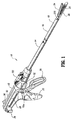
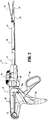
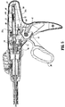
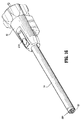
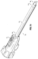
図1〜23は、一般に10として示される、ここに開示される外科用ステープル留めデバイスの1つの好ましい実施形態を示す。簡単に述べると、外科用ステープル留めデバイス10は、ハンドルアセンブリ12および細長の本体14を備える。細長の本体14の長さは、特定の外科手順に合うように変化し得る。細長の本体14は、デバイス10についての長手方向軸を規定する。交換可能なローディングユニットすなわちDLU 16は、細長の本体14の遠位端に取り外し可能に固定される。ローディングユニット16は、細長の本体14の伸長部を形成する近位本体部分18と、カートリッジアセンブリ22を備える遠位のツールアセンブリ20と、アンビルアセンブリ24とを備える。ツールアセンブリ20は、細長の本体14の長手方向軸に対して実質的に垂直な軸の周りで、本体部分18に旋回可能に接続される。カートリッジアセンブリ22は、複数のステープルを収容する。アンビルアセンブリ24は、カートリッジアセンブリ22から間隔を空けた開いた位置と、カートリッジアセンブリ24と近接して整列された、隣接する位置またはクランプ留めされた位置との間でカートリッジアセンブリ22に関して動くことが可能である。ステープルは、身体組織内にステープルの列を適用するためにカートリッジアセンブリ22内に収容される。例えば、示される実施形態において、ステープルの列は、約30mm〜約60mmの長さを有し得る、直線状のステープルの列である。他のステープルの構成および長さが想定される。
1-23 illustrate one preferred embodiment of the surgical stapling device disclosed herein, generally designated as 10. Briefly, the
ハンドルアセンブリ12は、固定ハンドル部材26、可動ハンドルまたはトリガ28、およびバレル部分30を備える。回転可能な部材32は、好ましくは、バレル部分30の前端に回転可能に設置され、そして、細長の本体14に固定されて、ハンドルアセンブリ12に関する細長の本体14の回転を容易にする。関節接合(articulation)レバー122は、バレル部分30の遠位部分の上に支持され、そして、本明細書において以下に記載されるような様式で、ローディングユニット16の本体部分18に関するツールアセンブリ20の関節接合をもたらすように作動可能である。一対の戻りノブ(return knob)36が、バレル部分30に沿って可動式に支持される。
Handle
図4〜7を参照すると、ハンドルアセンブリ12は、ハウジング38を備え、このハウジング38は、好ましくは、プラスチック成形されたハウジングの半セクション38aおよび38bから形成される。あるいは、金属(例えば、ステンレス鋼)を含む他の材料を用いてハウジングを形成することも可能である。ハウジング38は、ハンドルアセンブリ12の固定ハンドル26とバレル部分30とを形成する(図1を参照のこと)。可動ハンドル28は、円筒形の部材40の周りで、ハウジングの半セクション38aと38bとの間に回転可能に支持される。この円筒形の部材40は、可動ハンドル28の開口部41内に受容される。付勢部材42(好ましくは、ねじれバネである)は、可動ハンドル28を、固定ハンドル26から離れるように非圧縮位置へと推し進める。可動ハンドル28は、旋回部材47を受容する寸法にされた一対の貫通穴46を備える。つめ48は、旋回部材47の上に回転可能に支持され、そして、バネ50によって、作動シャフト52に向けて付勢される。
4-7, the
作動シャフト52は、ハウジング38のバレル部分30内で、引き込み位置と前進位置との間でスライド可能に支持され、そして、凹部54を規定する遠位端を備え、この凹部54は、発射ロッド58の近位端56を回転可能に受容するように構成される。バネにより付勢された引き込みアーム57は、ハウジングの半セクション38aと38bとの間に回転可能に設置され、そして、伸長部57aを備える。伸長部57aは、作動シャフト52内に形成されたスロット59(図4)内に位置決めされて、作動シャフト52を、完全に引っ込められた位置へと推し進める。作動シャフト52は、歯のついたラック60を備える。つめ48は、係合フィンガー62を有し、この係合フィンガー62は、バネ50によって、作動シャフト52の歯のついたラック60に向けて付勢される。可動ハンドル28が作動されるとき、すなわち、バネ42の付勢に逆らって固定ハンドル26に向けて圧縮されるとき、つめ48の係合フィンガー62は、作動シャフト52の歯のついたラック60を係合して、作動シャフト52と発射ロッド58とを遠位に進める。ローディングユニット16の近位端が、外科用ステープル留めデバイス10の細長の本体14と係合されるとき、発射ロッド58の遠位端は、ローディングユニット16の駆動アセンブリ212の近位端を係合する。
Actuating
外科用ステープル留めデバイスは、使い捨てのローディングユニットすなわち「DLU」を備える。所望のステープルのサイズと、所望のステープル列の長さを有するローディングユニットが、デバイスと共に組み立てられる。ローディングユニットは、関節接合を提供しない近位本体部分またはローディングユニットに関して関節接合し得るツールアセンブリを備え得る。ローディングユニットは、直線状のステープル列または他のステープルの構成を有するツールアセンブリを備え得る。ステープルをローディングユニットから発射した後、ローディングユニットは、デバイスから取り外され得、そして新しいローディングユニットが、デバイスと共に組み立てられ得る。 The surgical stapling device comprises a disposable loading unit or “DLU”. A loading unit having the desired staple size and the desired staple row length is assembled with the device. The loading unit may comprise a proximal body portion that does not provide articulation or a tool assembly that can articulate with respect to the loading unit. The loading unit may comprise a tool assembly having a linear staple row or other staple configuration. After firing the staples from the loading unit, the loading unit can be removed from the device and a new loading unit can be assembled with the device.
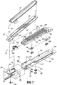
図1および7〜9を参照すると、関節接合ツールアセンブリを有するローディングユニットが示される。ローディングユニット16は、ツールアセンブリ20、近位本体部分18、および設置アセンブリ202を備える(図9)。本体部分18は、以下に詳細に考察されるような様式で細長の本体14の遠位端を解放可能に係合するよう適合された近位端を有する。設置アセンブリ202は、本体部分18の遠位端に旋回式に固定され、そして、ツールアセンブリ20の近端に確定的に固定される。設置アセンブリ202の旋回の動きは、ツールアセンブリ20を旋回させ、その結果、ツールアセンブリ20の長手方向軸が、細長の本体14の長手方向軸に関して整列する。細長の本体14の長手方向軸に対して実質的に垂直な軸の周りでの設置アセンブリ202の旋回の動きは、ツールアセンブリ20の長手方向軸が細長の本体14の長手方向軸と整列した非関節接合位置と、ツールアセンブリ20の長手方向軸と細長の本体14の長手方向軸に対してある角度に配置された関節接合位置との間で、ツールアセンブリ20の関節接合をもたらす。
1 and 7-9, a loading unit having an articulating tool assembly is shown. The
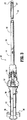
図7〜9を参照すると、ツールアセンブリ20は、カートリッジアセンブリ22およびアンビルアセンブリ24を備える。アンビルアセンブリ24は、複数のステープル変形くぼみ30(図8)を有するアンビル部分28と、アンビル部分28の上面に固定されたカバープレート32とを備える。カバープレート32およびアンビル部分28は、カバープレート32とアンビル部分28との間に空洞34を規定する。カバープレート32は、ローディングユニット16の作動中に組織を挟んで締め付けること、そして、駆動アセンブリ212がローディングユニット16を通って進むことを防止する。長手方向のスロット38は、アンビル部分28を通って延び、駆動アセンブリ212の保持フランジ40の通過を容易にする。アンビル部分28上に形成されるカム表面42は、駆動アセンブリ212の保持フランジ40上に支持される一対のカム部材40aによって係合されるように位置決めされて、アンビルアセンブリおよびカートリッジアセンブリの接近をもたらす。一対の旋回部材211および一対の安定化部材215が、アンビル部分28の上に形成される。
With reference to FIGS. 7-9, the
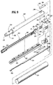
カートリッジアセンブリ22は、ステープルカートリッジ220を受容するような寸法および構成にされた細長の支持チャネル218を規定するキャリア216を備える。キャリア216は、キャリア216内に規定された一対の肩部217と一対のスロット213とを有する。一対のスロット213は、一対の旋回部材211を受容して、アンビル部分28がカートリッジアセンブリ22に関して旋回することを可能にする。一対の安定化部材215の各々は、それぞれの肩部217を係合して、アンビル部分28が旋回部材211の周りで旋回されるときに、アンビル部分28がステープルカートリッジ220に関して軸方向にスライドすることを防止する。それぞれステープルカートリッジ220および細長の支持チャネル218に沿って形成される対応するタブ222およびスロット224は、支持チャネル218内の固定位置においてステープルカートリッジ220を保持するように機能する。ステープルカートリッジ220上に形成される一対の支持支柱223は、キャリア216の側壁上に存在するように位置決めされ、さらにステープルカートリッジ220を支持チャネル218内に安定化する。
The
ステープルカートリッジ220は、複数のステープルまたは留め具226およびプッシャー228を受容するための保持スロット225(図7)を備える。複数の側方に間隔を空けた長手方向のスロット230は、ステープルカートリッジ220を通って延びて、作動スレッド234の直立するカムウェッジ232(図7)に適合する。中央の長手方向スロット282は、実質的にステープルカートリッジ220の長さに沿って延びて、駆動アセンブリ212の通過を容易にする(図9)。外科用ステープル留めデバイス10の作動中、駆動アセンブリ212は、発射ロッド58により進められる。駆動アセンブリ212は、作動スレッド234と接しており、そして、ステープルカートリッジ220の長手方向のスロット230を通して作動スレッド234を押して、続いてカムウェッジ232を進めて、プッシャー228と接触させる。プッシャー228は、留め具の保持スロット225内でカムウェッジ232に沿って垂直方向に平行移動し、そして、保持スロット225からアンビルアセンブリ24のステープル変形くぼみ30(図8)内へと留め具226を推し進める。
駆動アセンブリ212は、動作ヘッド268をもつ駆動梁266を備える。駆動梁266の動作ヘッド268の遠位端は、垂直方向の支持支柱278(図9)により規定され、この支持支柱278は、ナイフブレード280と、ステープル留め手順の間に作動スレッド234の一部を係合する接合表面283とを支持する。ナイフブレード280は、ステープルカートリッジ220内の中央の長手方向のスロット282を通して作動スレッド234の後方にスライド式に平行移動して、ステープル留めされた身体組織の列の間に切開部を形成するように位置決めされる。保持フランジ40は、垂直方向の支柱278から遠位に突出し、そして、その遠位端に円筒形のカムローラー40aを支持する。カムローラー40aは、アンビル部分28上のカム表面42を係合して、身体組織に対してアンビル部分28を把持するような寸法および構成である。
The
使用時に、使用者は、ハンドルアセンブリ12を操作して、組織を把持し、そして、ステープルを発射する。カートリッジアセンブリ22およびアンビルアセンブリ24を接近させて、組織を把持するために、可動ハンドル28は、固定ハンドル部材26に向かう方向に動かされる。可動ハンドル28は、ねじれバネ42の付勢に逆らって固定ハンドル26に向かって圧縮され、作動シャフト52を係合する。つめ48の係合フィンガー62は、作動シャフト52の歯のついたラック60を係合し、作動シャフト52および発射ロッド58を遠位に進める。
In use, the user operates the
発射ロッド58は、その遠位端において、駆動梁266を備える軸性の駆動アセンブリ212へと接続され、その結果、発射ロッド58の前進により、駆動梁266の前進が達成される。駆動梁266が前進すると、カムローラー40aが動いて、アンビル部分28のカム表面42と係合し、アンビル部分28をカートリッジ220の方向に推し進めて、カートリッジアセンブリ22とアンビルアセンブリ24とを接近させ、そして、そのカートリッジアセンブリ22とアンビルアセンブリ24との間に組織を把持する。
The firing
可動ハンドル28が作動されて、カートリッジアセンブリ22とアンビルアセンブリ24とを接近させた後、付勢部材42は、固定ハンドル26から間隔を空けたその非圧縮位置へとハンドルを戻す。
After
いったん組織が把持されると、ステープル留めデバイス10を発射するために、可動ハンドル28が、作動ストロークにより固定ハンドル部材26に向かって動かされ、この間、つめ48の係合フィンガー62は、作動シャフト52の歯のついたラック60を係合して、さらに、作動シャフト52および発射ロッド58を遠位に進める。ローディングユニット16から全てのステープルを発射するためには、1回以上の作動ストロークが必要とされ得る。発射ロッド58が上述の様式で進められるとき、駆動梁266は、遠位に進められ、そして、ステープルカートリッジ220を通して作動スレッド234を係合し、同時に、ナイフ280を用いて組織を切断し、そして、プッシャー228を駆動して、その後、カートリッジからステープル226を射出する。異なる長さのステープル列を有するローディングユニットが使用され得、そして、作動ストロークの回数はそれに従って変化する。ツールアセンブリの構造および動作は、米国特許第5,865,361号(その開示は、本明細書において、本明細書により参考として援用される)に開示される特定の実施形態に従い得る。
Once the tissue is grasped, the
細長の本体14は、図5に示されるように回転可能な部材32内に設置され、そして、この回転可能な部材32は、細長の本体14と、ツールアセンブリ20を備えるローディングユニット16とが、長手方向軸の周りで回転することを可能にするように、ハンドルアセンブリ12に取り付けられる。回転可能な部材32は、1以上の管状または円錐状の部材から形成され、そして、ツールアセンブリ20を、デバイス10の長手方向軸に関して関節接合するための関節接合作動機構を収容する。関節接合作動機構は、関節接合レバー122(図6)を備える。関節接合レバー122は、細長の本体14を通って延びる関節接合アームに作動可能に接合される。関節接合レバー122は、ツールアセンブリ20の予め決定された程度の関節接合を規定するための機構に接続され得る。関節接合レバー122の動作および構造は、米国特許出願公開第2004/0232201号(その開示は、本明細書において、本明細書により参考として援用される)に記載されるようなものであり得る。関節接合レバー122は、旋回ピンの周りで回転可能な部材32上に設置され、そして、関節接合アームへと取り付けられ、その結果、旋回ピンの周りでのレバー122の回転は、関節接合アームの長手方向の動きをもたらす。ローディングユニット16が細長の本体14の上に設置されるとき、関節接合アームは、細長の本体14を通って延び、そして、ローディングユニット16の関節接合リンク256(図9)へと取り付けられる。関節接合レバー122は、外科用ステープル留めデバイス10の使用者によって回転されて、ツールアセンブリ20を関節接合し得る。関節接合レバー122が第一の方向に回転されるとき、レバーに取り付けられた関節接合アームは、遠位方向に進められる。関節接合アームがローディングユニット16の関節接合リンク256を進め、そして、旋回心軸244の周りで設置アセンブリ202を旋回させて、ツールアセンブリ20を第一の方向に関節接合する。関節接合レバー122が第二の方向に回転されるとき、レバーに取り付けられた関節接合アームは、近位方向に引っ込められる。関節接合アームは、ローディングユニット16の関節接合リンク256を引っ込め、そして、旋回心軸244の周りで設置アセンブリ202を旋回させて、ツールアセンブリ20を第二の方向に関節接合する。
The
図6に示されるように、ローディングユニット16は、細長の本体14の遠位端上に取り外し可能に設置される。ローディングユニット16の本体部分18は、第一のハウジング250と第二のハウジング252とを備え、これらのハウジングは、軸性の駆動アセンブリ212の前進を可能にするためのチャネル253を規定する(図9)。ハウジング250および252はまた、関節接合リンク256のためのスロットを規定する。ハウジング250および252は、外部の円筒251内に受容される。ハウジング250および252の近位端は、挿入先端193を規定し、この上に、一対の出張り254が形成される。出張り254は、細長の本体14との解放可能な接続を形成し、その結果、ローディングユニット16は、細長の本体14の上に設置され得、そして、細長の本体14から取り外され得る。一対のブローアウトプレート(blowout plate)255が、近位本体部分18の遠位端に近接して、そして、設置アセンブリ202に近接して位置決めされる。ブローアウトプレート255は、ツールアセンブリ20の関節接合および発射の間に、駆動アセンブリ212を支持する。ブローアウトプレート255の構造および動作は、米国特許出願公開第2004/0232201号(その開示は、本明細書において、本明細書により参考として援用される)においてより完全に記載される。
As shown in FIG. 6, the
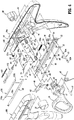
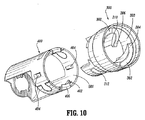
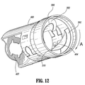
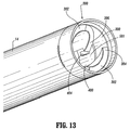
細長の本体14の遠位端は、その上部にローディングユニット16を設置するための先端アセンブリ301を規定する。図10〜15および18は、本開示に従う先端アセンブリ301を示す。この先端アセンブリ301は、回転式に固定されるように細長の本体14の遠位端に設置されたリング300と、このリング300に対し可動に設置されたヨーク400とを備える(図10および14を参照のこと)。このリング300は、通路303を規定し、この通路303内で、2つのらせん状の案内傾斜路302が形成される。案内傾斜路の各々は、遠位端304と、近位端306と、近位端306に隣接する縁部310とを有する。リング300の上部にヨーク400を設置するために、溝312が、リング300の内面に規定される(図10を参照のこと)。
The distal end of the
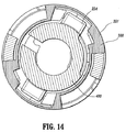
可動ヨーク400は、ローディングユニット16上の出張り254と相互作用するための少なくとも1つの突出部を有する。図11に示されるように、突出部は、タブ402および停止部材(stop)404が受容空間501を規定するように対に整列された2つのタブ402および2つの停止部材404を備える。ヨーク400の遠位端はまた、ヨーク400が第一の最初の位置から第二の位置へとリング300に関して回転可能となるように、リング300の溝312と協働する隆起部406を有する。ヨーク400が回転すると、案内傾斜路302の近位端306に関するタブおよび停止部材の位置が変化する。図11に示されるような、ヨーク400の第一の位置において、タブ402および停止部材404の対は、案内傾斜路302のうちの一方の近位端306の1つに近接して配置され、その結果、受容空間501が、ローディングユニット16の出張り254のうち1つを受容するために位置決めされる。図12に示されるようなヨーク400の第二の位置において、タブ402および停止部材404の対は、受容空間501と、その内部に配置される出張り254とが、縁部310の下に配置されるように位置決めされる。
The
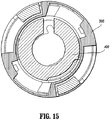
ローディングユニット16は、先端アセンブリ301内へと挿入され、その結果、挿入先端193が通路303内へと挿入される。出張り254は、リング300の通路303内へと進められ、そして、案内傾斜路302の遠位端304と接する(図11を参照のこと)。ローディングユニット16が方向A(図12を参照のこと)に回転されるとき、出張り254は、案内傾斜路302上で、案内傾斜路302の近位端306に向けて案内され、そして、ヨーク400の受容空間501内へと落ちる。図14は、受容空間501内にある出張り254を示す。先端アセンブリ301は、依然として第一の位置にあり、そして、停止部材404およびタブ402が、出張り254の両側に、かつ、案内傾斜路302のうちの一方の近位端306に近接して配置される。この位置において、ローディングユニット16は遠位に動かされ、そして、細長の本体14から取り外され得る。使用者は、引き続きローディングユニット16を方向Aに回転し、その結果、出張り254がタブ402に対して押し付け、それによって、可動ヨーク400を、図12に示されるような第二の位置へと回転させる。出張り254は、縁部310の下に置かれる。図15は、縁部310の下に位置決めされた出張り254を示す。停止部材404は、ローディングユニット16がヨーク400に関して回転することを防止する。こうして、ローディングユニット16は先端アセンブリ301内に捕捉され、ヨーク400を回転させずにローディングユニット16を動かすことはできない。
The
ローディングユニット16が、細長の本体14の遠位端上に設置されるとき、発射ロッド58の遠位端が、駆動アセンブリ212の近位端に接続される。駆動アセンブリ212の近位端は、発射ロッド58の遠位端を受容するためのポートホールをもつ駆動部材272を備える。ローディングユニット16が、ローディングユニットの設置の間に回転されるとき、関節接合リンク256が動いて、関節接合アームの遠位端上に係合構造体により係合される。
When the
デバイスからローディングユニット16を取り外すために、ローディングユニット16は、方向Aとは逆方向に回転され、ヨーク400がローディングユニット16と共に回転する。出張り254は、それにより、縁部310から離れて動かされる。ローディングユニットが回転されるとき、関節接合リンク256および関節接合アームは互いに係合から離れるように動かされる。ローディングユニット16は、出張り254が案内傾斜路302に従って遠位端304に向かって進み、DLUを遠位に動かすように、ローディングユニット16を引き続き回転させることによって、デバイスから取り外され得る。DLUを細長の本体14から取り外す際、発射ロッド58は、駆動アセンブリ212から脱係合される。
To remove the
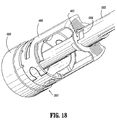
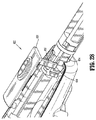
本開示に従う外科用ステープル留めデバイス10は、図16〜23に示されるように、センサー機構513およびロッキング構造体510を備える。センサー機構513およびロッキング構造体510は、先端アセンブリ301(図17)と相互作用して、ローディングユニット16を細長の本体14上に固定する。センサー機構513およびロッキング構造体510は、細長の本体14からローディングユニット16を解放する。ロッキング構造体510は、ローディングユニット16が細長の本体14上に搭載されるまで、発射ロッド58を適所にロックする。
The
センサー機構513は、遠位端を有するセンサー円筒502を備え、このセンサー円筒は、図18に示されるように、溝504をもつ。先端アセンブリ301のヨーク400は、突出部407を有し、この突出部407は、溝504を係合し、そして、ヨーク400の動きをセンサー円筒502に固定する。ローディングユニット16を搭載する間に、ヨーク400が回転されるとき、センサー円筒502は、同じ方向に回転される。センサー円筒502の近位端は、ロッキング構造体510に接続される。ロッキング構造体510は、デバイス10の使用者に対しアクセス可能となるように、細長の本体14の近位端において、または、ハンドルアセンブリ12上に、ボタン514または他の操作可能なアクチュエータを備える。例えば、ボタン514は、図19において、回転可能な部材32の上に示される。ボタン514は、センサー円筒502に向かって延びるボタンの舌部512を有する。解放フランジ508が、センサー円筒502に取り付けられ、そして、ボタンの舌部512から離れた第一の位置(図20)から、解放フランジ508の動きが、ロッキング構造体510のボタンの舌部512によってブロックされる第二の位置(図19)へと、センサー円筒502と共に回転する。ボタン514は、バネによって、遠位方向に付勢される。
The
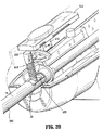
プランジャー516は、発射ロッド58と相互作用する。発射ロッド58の近位端524は、内部に規定されるノッチ526(図20〜23において最良に見られる)を有する。プランジャー516は、ノッチ526において発射ロッド58を係合するための第一の端部と、ボタン514と連絡するように位置決めされた傾斜表面522をもつ第二の端部とを有する(図21および23)。プランジャー516は、発射ロッド58から離れる方向に付勢される。
最初の位置において、ローディングユニット16がデバイス10上に設置される前に、ロッキング構造体510は、ノッチ526内で発射ロッド58を係合し、発射ロッド58の前進を防止する。解放フランジ508は、ボタン514がプランジャー516のノッチ526との係合状態を維持するように、ボタン514が遠位に動くことを防止する。ローディングユニット16がデバイス上に設置されると、ヨーク400が回転し、それによって、センサー円筒502が回転する。解放フランジ508は、ボタンの舌部512から離れて動き、ボタン514が遠位に動くことを可能にする。図23に示されるように、ボタン514は、プランジャー516がノッチ526から離れて動くことを可能にする。可動ハンドル28が操作されて、デバイス10が組織を把持し、そしてステープルを発射するように作動されるとき、ロッキング構造体510は、発射ロッド58から脱係合され、発射ロッド58が動くことが可能となる。解放フランジ508がボタンの舌部512によってブロックされるとき、ローディングユニット16もまたデバイス10上にロックされ、センサー円筒502の回転が防止される。センサー円筒502が回転しないように防止される場合、デバイス10上にローディングユニット16を保持するヨーク400の回転が防止される。
In the initial position, before the
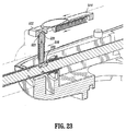
ローディングユニット16がデバイス10から取り外される予定の場合、図21に示されるように、ロッキング構造体510のボタン514がボタンのバネの付勢に逆らって動かされ、図20に示されるように、ボタンの舌部512を解放フランジ508から離して動かす。次いで、ローディングユニット16が回転され、そして、細長の本体14の上の先端アセンブリ301から取り外され得る。さらに、図21に示されるように、ボタン514がプランジャー516を下向きにノッチ526へ向けてカム作用するとき、ロッキング構造体510は、発射ロッド58を係合する。
If the
本開示に従うロッキング構造体および/またはセンサー機構は、外科用機器からのステープルカートリッジ、交換可能なツールアセンブリ、または他のエンドエフェクタのような任意の外科用ローディングユニットを固定するために使用され得、その一方で、これらの外科用ローディングユニットの解放を提供する。望ましくは、外科用ローディングユニットを解放および/またはロックするための操作可能なアクチュエータが、ハンドルアセンブリの近くに配置される。内視鏡機器において、操作可能なアクチュエータは、内視鏡のシャフトまたは細長の本体の近位端に、または、その近くに配置される。 The locking structure and / or sensor mechanism according to the present disclosure may be used to secure any surgical loading unit such as a staple cartridge from a surgical instrument, a replaceable tool assembly, or other end effector; On the other hand, it provides the release of these surgical loading units. Desirably, an operable actuator for releasing and / or locking the surgical loading unit is disposed near the handle assembly. In an endoscopic instrument, the manipulable actuator is located at or near the proximal end of the endoscope shaft or elongate body.
ローディングユニットを発射した後で、かつ、ローディングユニットを取り外す前に、引き込み機構が用いられる。引き込み機構は、継手ロッド82(図4)によって作動シャフト52の近位端に接続された戻りノブ36(図1)を備える。継手ロッド82は、ハウジングの半セクション38aおよび38bにおいて形成された細長のスロット83(図1)を通って延びる、右側の係合部分82aと左側の係合部分82bとを有し、そして、戻りノブ36を受容するように構成される。継手ロッド82の中央部分82cは、作動シャフト52の近位端に形成されたスロット84内でスライド可能に受容されるような寸法である。解放プレート86は、一対のピン88によって作動シャフト52の片側に支持される(図4)。ピン88は、解放プレート86を通して形成された、角度のついたカムスロット90内に位置決めされる。継手ロッド82は、解放プレート86の近位端に形成された開口部92を通って延びる。
A retraction mechanism is used after firing the loading unit and before removing the loading unit. The retraction mechanism includes a return knob 36 (FIG. 1) connected to the proximal end of the
使用の際、ノブ36が外科医によって後方に引っ張られる場合、ロッド82が作動シャフト52のスロット84内をスライドするとき、継手ロッド82は、最初に、解放プレート86を作動シャフト52に関して後方に動かす。これが生じると、ピン88が、解放プレート86を下向きに作動シャフト52の歯のついたラック60を覆う位置へとカム作用して、歯のついたラック60からつめ48のフィンガー62を脱係合する。継手ロッド82がスロット84の後端84aを係合する位置まで後方に引っ張られる場合、ノブ36のさらなる後方への動きが、作動シャフト52および発射ロッド58の近位への動きをもたらす。
In use, when the
フック96は、作動シャフト52の上面に形成されたスロット98内に支持される。フック96は、継手ロッド82を受容するような寸法にされた貫通穴96aを備える。フック96の前端は、バネ100の一方のループ状の端部100aを受容するように構成された上向きの部分98を備える。バネ100の反対側の端部は、作動シャフト52の上に形成された支柱102を受容するような寸法にされたループ100bを備える。バネ100は、継手ロッド82を、作動シャフト52内のスロット84の前端に向けて推し進めるために、張った状態に維持される。継手ロッド82が、作動シャフト52のスロット84の前端に位置決めされるとき、解放プレート86は、作動シャフト52の歯のついたラック60の上の高い位置において保持またはカム作用される。
The
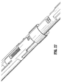
図24〜28に示される別の実施形態において、ロッキング構造体600は、ボタンアセンブリ602と細長のハウジング604とを備える。ロッキング構造体600は、ローディングユニット620をロックするための第一の位置(図27)と、ローディングユニット620のロックを外し、脱係合するための第二の位置(図26)とを有する。
In another embodiment shown in FIGS. 24-28, the locking structure 600 comprises a
細長のハウジング604は、外部の円筒622と、管状のハウジング612と、細長のハウジング604の遠位端604bにあるローディング部分606とを備える。ロッキングシャフト614は、細長のハウジング604を通って延び、そして、管状のハウジング612内の凹部によって受容されるような形状であり、その結果、このロッキングシャフト614は、管状のハウジング612に関してスライド可能であり、そして、管状のハウジング612に関して回転式に固定される。管状のハウジング612およびロッキングシャフト614はまた、ハウジング612とシャフト614との間にバネ618を受容するためのノッチ613を規定する(図26)。ローディング部分606は、ローディングユニット620上の1以上の出張り610を受容するように構成され、そして、デバイス10上へのローディングユニット620の動きを導く。
The
管状のハウジング612およびロッキングシャフト614は、ローディングユニット620の出張り610を受容し、そしてロックするための空間611を規定する。管状のハウジング612は、空間611の近位側にシェルフ616を、空間611の遠位側に縁部612aを、そして、空間611の側方に縁部612bおよび612cを有する。ロッキングシャフト614は、遠位に面する表面614aと、別の遠位に面する表面614cと、表面614aと表面614cとの間を延びる長手方向の表面614bとを有する。図26において最良に見られるように、表面614a、614bおよび614cにより規定されるロッキングシャフト614の遠位端は、階段状の形状を有する。
シール624およびエンドキャップ626が、細長のハウジング604の近位端604aに配置される(図25)。シール624は、円形の形状であり、そして、別個のチャンバを規定する2つの壁を備える。好ましい実施形態において、シール624およびエンドキャップ626は、図25に最良に見られるように、管状のハウジング612の上をスライドする。シール624は、3つのチャンバを有する。この3つのチャンバは、ロッキングシャフト614、管状のハウジング612、および関節接合ロッド(図示せず)を受容する。エンドキャップ626は、シール624と連絡し、組み立てた際には、シール624が、外部の円筒622を押し付ける。
A
ロッキング構造体600は、細長のハウジング604の近位端に位置するボタンアセンブリ602を備え、これは、第一のロックされた位置と、第二のロックされていない位置との間で可動である。ボタンアセンブリ602は、ボタン631を遠位に付勢する戻りバネ633(図25)を備える。ボタン631は、ロッキングシャフト614上のスロット634を係合する突出部632を規定する。スロット634と突出部632との相互作用により、ボタン631が使用者によって動かされるとき、ボタン631およびロッキングシャフト614は、第一の位置と第二の位置との間で可動である。
The locking structure 600 includes a
図24〜26に示されるように、細長のハウジング604は、出張り610を受容するような寸法にされたローディング部分606を規定する。管状のハウジング612は、案内チャネル608を形成する溝を有し、この案内チャネル608は、ローディングユニット620の動きを導く。ローディングユニット620がローディング部分606内に挿入されるとき、出張り610は、ロッキングシャフト614の表面614aに接し、ロッキングシャフト614を近位に動かす。管状のハウジング612の上に位置するシェルフ616は、出張り610に接し、従って、近位へのさらなる動きを防止する。ローディングユニット620は、縁部612cに向けて、図26に示される方向Aに回転される。出張り610が表面614cと整列されるとき、ロッキングシャフト614は、バネ618の影響下で遠位に動く。出張り610は、図26に示されるように、縁部614b、614cと、表面612a、612cとの間に捕捉され、回転の動きおよび長手方向の動きを防止する。使用者がボタンアセンブリ630をバネ618の付勢に逆らって近位に動かすとき、ロッキングシャフト614が後方に動かされ、ロッキング構造体600がローディングユニット620を脱係合し(図26)、そして、ローディングユニット620が取り外され得る。ローディングユニット620を取り外すために、ボタンアセンブリ630が後方に動かされ、ロッキングシャフト614を管状のハウジング612を横切って近位にスライドさせる。ローディング部分606を方向Aとは反対方向に回転させることによって、ローディングユニット620がローディング部分606から取り外される。
As shown in FIGS. 24-26, the
本明細書において開示される実施形態に対して種々の改変がなされ得ることが理解される。例えば、上記のロックアセンブリは、種々の外科用機器(ローディングユニットを備え、内視鏡ステープラー上での使用に限定されない)へと組み込まれ得る。さらに、ローディングユニットは、開示されるものとは対照的に、外科用機器の挿入先端部を受容するように構成されてもよい。従って、上記の明細書は、限定するものとして解釈されるべきではなく、単に、種々の実施形態の例示として解釈されるべきである。当業者は、添付の特許請求の範囲の精神および範囲内で、他の改変を想定する。 It will be understood that various modifications may be made to the embodiments disclosed herein. For example, the lock assembly described above may be incorporated into various surgical instruments (including a loading unit and not limited to use on an endoscopic stapler). Further, the loading unit may be configured to receive an insertion tip of a surgical instrument as opposed to what is disclosed. Therefore, the above specification should not be construed as limiting, but merely as exemplifications of various embodiments. Those skilled in the art will envision other modifications within the scope and spirit of the claims appended hereto.
10:外科用ステープル留めデバイス
12:ハンドルアセンブリ
14:細長の本体
16、620:ローディングユニット、DLU
20:ツールアセンブリ
22:カートリッジアセンブリ
24:アンビルアセンブリ
28:可動ハンドルまたはトリガ/アンビル部分
30:バレル部分/くぼみ
32:回転可能な部材/カバープレート
38:ハンドルアセンブリのハウジング
42:付勢部材またはバネ/カム表面
52:作動シャフト
58:発射ロッド
212:駆動アセンブリ
254、610:出張り
510、600:ロッキング構造体
512、632:ボタンの突出部、舌部
513:センサー構造体
514、631:ボタン
602、630:ボタンアセンブリ
604:細長のハウジング
608:案内チャネル
614:ロッキングシャフト
10: Surgical stapling device 12: Handle assembly 14:
20: tool assembly 22: cartridge assembly 24: anvil assembly 28: movable handle or trigger / anvil part 30: barrel part / recess 32: rotatable member / cover plate 38: handle assembly housing 42: biasing member or spring / Cam surface 52: Actuating shaft 58: Firing rod 212:
Claims (1)
Applications Claiming Priority (2)
| Application Number | Priority Date | Filing Date | Title |
|---|---|---|---|
| US11/891,441 | 2007-08-10 | ||
| US11/891,441 US7753246B2 (en) | 2007-01-31 | 2007-08-10 | Surgical instrument with replaceable loading unit |
Related Parent Applications (1)
| Application Number | Title | Priority Date | Filing Date |
|---|---|---|---|
| JP2008200269A Division JP5382907B2 (en) | 2007-08-10 | 2008-08-01 | Surgical instrument with replaceable loading unit |
Related Child Applications (1)
| Application Number | Title | Priority Date | Filing Date |
|---|---|---|---|
| JP2014230319A Division JP2015042316A (en) | 2007-08-10 | 2014-11-13 | Surgical instrument with replaceable loading unit |
Publications (2)
| Publication Number | Publication Date |
|---|---|
| JP2013144199A true JP2013144199A (en) | 2013-07-25 |
| JP5744099B2 JP5744099B2 (en) | 2015-07-01 |
Family
ID=39869936
Family Applications (3)
| Application Number | Title | Priority Date | Filing Date |
|---|---|---|---|
| JP2008200269A Expired - Fee Related JP5382907B2 (en) | 2007-08-10 | 2008-08-01 | Surgical instrument with replaceable loading unit |
| JP2013092020A Active JP5744099B2 (en) | 2007-08-10 | 2013-04-25 | Surgical instrument with replaceable loading unit |
| JP2014230319A Withdrawn JP2015042316A (en) | 2007-08-10 | 2014-11-13 | Surgical instrument with replaceable loading unit |
Family Applications Before (1)
| Application Number | Title | Priority Date | Filing Date |
|---|---|---|---|
| JP2008200269A Expired - Fee Related JP5382907B2 (en) | 2007-08-10 | 2008-08-01 | Surgical instrument with replaceable loading unit |
Family Applications After (1)
| Application Number | Title | Priority Date | Filing Date |
|---|---|---|---|
| JP2014230319A Withdrawn JP2015042316A (en) | 2007-08-10 | 2014-11-13 | Surgical instrument with replaceable loading unit |
Country Status (6)
| Country | Link |
|---|---|
| US (6) | US7753246B2 (en) |
| EP (2) | EP2644108B1 (en) |
| JP (3) | JP5382907B2 (en) |
| AU (1) | AU2008203083B2 (en) |
| CA (2) | CA2875149C (en) |
| ES (1) | ES2768254T3 (en) |
Families Citing this family (635)
| Publication number | Priority date | Publication date | Assignee | Title |
|---|---|---|---|---|
| US5865361A (en) | 1997-09-23 | 1999-02-02 | United States Surgical Corporation | Surgical stapling apparatus |
| US20070084897A1 (en) | 2003-05-20 | 2007-04-19 | Shelton Frederick E Iv | Articulating surgical stapling instrument incorporating a two-piece e-beam firing mechanism |
| US9060770B2 (en) | 2003-05-20 | 2015-06-23 | Ethicon Endo-Surgery, Inc. | Robotically-driven surgical instrument with E-beam driver |
| US8215531B2 (en) | 2004-07-28 | 2012-07-10 | Ethicon Endo-Surgery, Inc. | Surgical stapling instrument having a medical substance dispenser |
| US11896225B2 (en) | 2004-07-28 | 2024-02-13 | Cilag Gmbh International | Staple cartridge comprising a pan |
| US7934630B2 (en) | 2005-08-31 | 2011-05-03 | Ethicon Endo-Surgery, Inc. | Staple cartridges for forming staples having differing formed staple heights |
| US11246590B2 (en) | 2005-08-31 | 2022-02-15 | Cilag Gmbh International | Staple cartridge including staple drivers having different unfired heights |
| US11484312B2 (en) | 2005-08-31 | 2022-11-01 | Cilag Gmbh International | Staple cartridge comprising a staple driver arrangement |
| US10159482B2 (en) | 2005-08-31 | 2018-12-25 | Ethicon Llc | Fastener cartridge assembly comprising a fixed anvil and different staple heights |
| US7669746B2 (en) | 2005-08-31 | 2010-03-02 | Ethicon Endo-Surgery, Inc. | Staple cartridges for forming staples having differing formed staple heights |
| US9237891B2 (en) | 2005-08-31 | 2016-01-19 | Ethicon Endo-Surgery, Inc. | Robotically-controlled surgical stapling devices that produce formed staples having different lengths |
| US20070106317A1 (en) | 2005-11-09 | 2007-05-10 | Shelton Frederick E Iv | Hydraulically and electrically actuated articulation joints for surgical instruments |
| US8708213B2 (en) | 2006-01-31 | 2014-04-29 | Ethicon Endo-Surgery, Inc. | Surgical instrument having a feedback system |
| US20120292367A1 (en) | 2006-01-31 | 2012-11-22 | Ethicon Endo-Surgery, Inc. | Robotically-controlled end effector |
| US11793518B2 (en) | 2006-01-31 | 2023-10-24 | Cilag Gmbh International | Powered surgical instruments with firing system lockout arrangements |
| US20110295295A1 (en) | 2006-01-31 | 2011-12-01 | Ethicon Endo-Surgery, Inc. | Robotically-controlled surgical instrument having recording capabilities |
| US20110024477A1 (en) | 2009-02-06 | 2011-02-03 | Hall Steven G | Driven Surgical Stapler Improvements |
| US8820603B2 (en) | 2006-01-31 | 2014-09-02 | Ethicon Endo-Surgery, Inc. | Accessing data stored in a memory of a surgical instrument |
| US7845537B2 (en) | 2006-01-31 | 2010-12-07 | Ethicon Endo-Surgery, Inc. | Surgical instrument having recording capabilities |
| US11224427B2 (en) | 2006-01-31 | 2022-01-18 | Cilag Gmbh International | Surgical stapling system including a console and retraction assembly |
| US11278279B2 (en) | 2006-01-31 | 2022-03-22 | Cilag Gmbh International | Surgical instrument assembly |
| US7753904B2 (en) | 2006-01-31 | 2010-07-13 | Ethicon Endo-Surgery, Inc. | Endoscopic surgical instrument with a handle that can articulate with respect to the shaft |
| US8186555B2 (en) | 2006-01-31 | 2012-05-29 | Ethicon Endo-Surgery, Inc. | Motor-driven surgical cutting and fastening instrument with mechanical closure system |
| US8992422B2 (en) | 2006-03-23 | 2015-03-31 | Ethicon Endo-Surgery, Inc. | Robotically-controlled endoscopic accessory channel |
| US20070225562A1 (en) | 2006-03-23 | 2007-09-27 | Ethicon Endo-Surgery, Inc. | Articulating endoscopic accessory channel |
| EP2018248B1 (en) | 2006-05-19 | 2015-11-04 | Applied Medical Resources Corporation | Surgical stapler |
| US8322455B2 (en) | 2006-06-27 | 2012-12-04 | Ethicon Endo-Surgery, Inc. | Manually driven surgical cutting and fastening instrument |
| US8220690B2 (en) | 2006-09-29 | 2012-07-17 | Ethicon Endo-Surgery, Inc. | Connected surgical staples and stapling instruments for deploying the same |
| US10568652B2 (en) | 2006-09-29 | 2020-02-25 | Ethicon Llc | Surgical staples having attached drivers of different heights and stapling instruments for deploying the same |
| US8584921B2 (en) | 2006-10-06 | 2013-11-19 | Covidien Lp | Surgical instrument with articulating tool assembly |
| US8652120B2 (en) | 2007-01-10 | 2014-02-18 | Ethicon Endo-Surgery, Inc. | Surgical instrument with wireless communication between control unit and sensor transponders |
| US11291441B2 (en) | 2007-01-10 | 2022-04-05 | Cilag Gmbh International | Surgical instrument with wireless communication between control unit and remote sensor |
| US8684253B2 (en) | 2007-01-10 | 2014-04-01 | Ethicon Endo-Surgery, Inc. | Surgical instrument with wireless communication between a control unit of a robotic system and remote sensor |
| US8827133B2 (en) | 2007-01-11 | 2014-09-09 | Ethicon Endo-Surgery, Inc. | Surgical stapling device having supports for a flexible drive mechanism |
| US11039836B2 (en) | 2007-01-11 | 2021-06-22 | Cilag Gmbh International | Staple cartridge for use with a surgical stapling instrument |
| US7753246B2 (en) * | 2007-01-31 | 2010-07-13 | Tyco Healthcare Group Lp | Surgical instrument with replaceable loading unit |
| US8065790B2 (en) * | 2007-02-23 | 2011-11-29 | Continental Automotive Systems Us, Inc. | Bearing mounted sensor assembly |
| US7669747B2 (en) | 2007-03-15 | 2010-03-02 | Ethicon Endo-Surgery, Inc. | Washer for use with a surgical stapling instrument |
| US8893946B2 (en) | 2007-03-28 | 2014-11-25 | Ethicon Endo-Surgery, Inc. | Laparoscopic tissue thickness and clamp load measuring devices |
| US11857181B2 (en) | 2007-06-04 | 2024-01-02 | Cilag Gmbh International | Robotically-controlled shaft based rotary drive systems for surgical instruments |
| US8931682B2 (en) | 2007-06-04 | 2015-01-13 | Ethicon Endo-Surgery, Inc. | Robotically-controlled shaft based rotary drive systems for surgical instruments |
| US7753245B2 (en) | 2007-06-22 | 2010-07-13 | Ethicon Endo-Surgery, Inc. | Surgical stapling instruments |
| US11849941B2 (en) | 2007-06-29 | 2023-12-26 | Cilag Gmbh International | Staple cartridge having staple cavities extending at a transverse angle relative to a longitudinal cartridge axis |
| US8061576B2 (en) | 2007-08-31 | 2011-11-22 | Tyco Healthcare Group Lp | Surgical instrument |
| US8758391B2 (en) | 2008-02-14 | 2014-06-24 | Ethicon Endo-Surgery, Inc. | Interchangeable tools for surgical instruments |
| US9179912B2 (en) | 2008-02-14 | 2015-11-10 | Ethicon Endo-Surgery, Inc. | Robotically-controlled motorized surgical cutting and fastening instrument |
| US8573465B2 (en) | 2008-02-14 | 2013-11-05 | Ethicon Endo-Surgery, Inc. | Robotically-controlled surgical end effector system with rotary actuated closure systems |
| US8636736B2 (en) | 2008-02-14 | 2014-01-28 | Ethicon Endo-Surgery, Inc. | Motorized surgical cutting and fastening instrument |
| BRPI0901282A2 (en) | 2008-02-14 | 2009-11-17 | Ethicon Endo Surgery Inc | surgical cutting and fixation instrument with rf electrodes |
| US7866527B2 (en) | 2008-02-14 | 2011-01-11 | Ethicon Endo-Surgery, Inc. | Surgical stapling apparatus with interlockable firing system |
| US7819298B2 (en) | 2008-02-14 | 2010-10-26 | Ethicon Endo-Surgery, Inc. | Surgical stapling apparatus with control features operable with one hand |
| US11272927B2 (en) | 2008-02-15 | 2022-03-15 | Cilag Gmbh International | Layer arrangements for surgical staple cartridges |
| US9770245B2 (en) | 2008-02-15 | 2017-09-26 | Ethicon Llc | Layer arrangements for surgical staple cartridges |
| US9005230B2 (en) | 2008-09-23 | 2015-04-14 | Ethicon Endo-Surgery, Inc. | Motorized surgical instrument |
| US11648005B2 (en) | 2008-09-23 | 2023-05-16 | Cilag Gmbh International | Robotically-controlled motorized surgical instrument with an end effector |
| US7896214B2 (en) | 2008-09-23 | 2011-03-01 | Tyco Healthcare Group Lp | Tissue stop for surgical instrument |
| US7988028B2 (en) | 2008-09-23 | 2011-08-02 | Tyco Healthcare Group Lp | Surgical instrument having an asymmetric dynamic clamping member |
| US8628544B2 (en) | 2008-09-23 | 2014-01-14 | Covidien Lp | Knife bar for surgical instrument |
| US9386983B2 (en) | 2008-09-23 | 2016-07-12 | Ethicon Endo-Surgery, Llc | Robotically-controlled motorized surgical instrument |
| US8210411B2 (en) | 2008-09-23 | 2012-07-03 | Ethicon Endo-Surgery, Inc. | Motor-driven surgical cutting instrument |
| US8608045B2 (en) | 2008-10-10 | 2013-12-17 | Ethicon Endo-Sugery, Inc. | Powered surgical cutting and stapling apparatus with manually retractable firing system |
| US8517239B2 (en) | 2009-02-05 | 2013-08-27 | Ethicon Endo-Surgery, Inc. | Surgical stapling instrument comprising a magnetic element driver |
| US8444036B2 (en) | 2009-02-06 | 2013-05-21 | Ethicon Endo-Surgery, Inc. | Motor driven surgical fastener device with mechanisms for adjusting a tissue gap within the end effector |
| CA2751664A1 (en) | 2009-02-06 | 2010-08-12 | Ethicon Endo-Surgery, Inc. | Driven surgical stapler improvements |
| US8292154B2 (en) | 2009-04-16 | 2012-10-23 | Tyco Healthcare Group Lp | Surgical apparatus for applying tissue fasteners |
| US8220688B2 (en) | 2009-12-24 | 2012-07-17 | Ethicon Endo-Surgery, Inc. | Motor-driven surgical cutting instrument with electric actuator directional control assembly |
| US8851354B2 (en) | 2009-12-24 | 2014-10-07 | Ethicon Endo-Surgery, Inc. | Surgical cutting instrument that analyzes tissue thickness |
| WO2011159860A2 (en) | 2010-06-17 | 2011-12-22 | Carefusion 2200. Inc. | Systems, apparatuses and methods of tool exchange |
| US8783543B2 (en) | 2010-07-30 | 2014-07-22 | Ethicon Endo-Surgery, Inc. | Tissue acquisition arrangements and methods for surgical stapling devices |
| CN101966093B (en) * | 2010-09-28 | 2012-01-11 | 常州市康迪医用吻合器有限公司 | Cavity mirror surgical incision anastomat with replaceable nail bin |
| US11298125B2 (en) | 2010-09-30 | 2022-04-12 | Cilag Gmbh International | Tissue stapler having a thickness compensator |
| BR112013007717B1 (en) | 2010-09-30 | 2020-09-24 | Ethicon Endo-Surgery, Inc. | SURGICAL CLAMPING SYSTEM |
| US10945731B2 (en) | 2010-09-30 | 2021-03-16 | Ethicon Llc | Tissue thickness compensator comprising controlled release and expansion |
| US11849952B2 (en) | 2010-09-30 | 2023-12-26 | Cilag Gmbh International | Staple cartridge comprising staples positioned within a compressible portion thereof |
| US9364233B2 (en) | 2010-09-30 | 2016-06-14 | Ethicon Endo-Surgery, Llc | Tissue thickness compensators for circular surgical staplers |
| US9517063B2 (en) | 2012-03-28 | 2016-12-13 | Ethicon Endo-Surgery, Llc | Movable member for use with a tissue thickness compensator |
| US9301753B2 (en) | 2010-09-30 | 2016-04-05 | Ethicon Endo-Surgery, Llc | Expandable tissue thickness compensator |
| US9320523B2 (en) | 2012-03-28 | 2016-04-26 | Ethicon Endo-Surgery, Llc | Tissue thickness compensator comprising tissue ingrowth features |
| US11812965B2 (en) | 2010-09-30 | 2023-11-14 | Cilag Gmbh International | Layer of material for a surgical end effector |
| US8978954B2 (en) | 2010-09-30 | 2015-03-17 | Ethicon Endo-Surgery, Inc. | Staple cartridge comprising an adjustable distal portion |
| US9592050B2 (en) | 2010-09-30 | 2017-03-14 | Ethicon Endo-Surgery, Llc | End effector comprising a distal tissue abutment member |
| US9629814B2 (en) | 2010-09-30 | 2017-04-25 | Ethicon Endo-Surgery, Llc | Tissue thickness compensator configured to redistribute compressive forces |
| US9351730B2 (en) | 2011-04-29 | 2016-05-31 | Ethicon Endo-Surgery, Llc | Tissue thickness compensator comprising channels |
| US9220501B2 (en) | 2010-09-30 | 2015-12-29 | Ethicon Endo-Surgery, Inc. | Tissue thickness compensators |
| US9220500B2 (en) | 2010-09-30 | 2015-12-29 | Ethicon Endo-Surgery, Inc. | Tissue thickness compensator comprising structure to produce a resilient load |
| US8899461B2 (en) | 2010-10-01 | 2014-12-02 | Covidien Lp | Tissue stop for surgical instrument |
| US8695866B2 (en) | 2010-10-01 | 2014-04-15 | Ethicon Endo-Surgery, Inc. | Surgical instrument having a power control circuit |
| US8336754B2 (en) * | 2011-02-04 | 2012-12-25 | Covidien Lp | Locking articulation mechanism for surgical stapler |
| US8573463B2 (en) * | 2011-03-31 | 2013-11-05 | Covidien Lp | Locking articulation mechanism |
| CA2834649C (en) | 2011-04-29 | 2021-02-16 | Ethicon Endo-Surgery, Inc. | Staple cartridge comprising staples positioned within a compressible portion thereof |
| US9820741B2 (en) * | 2011-05-12 | 2017-11-21 | Covidien Lp | Replaceable staple cartridge |
| US9072535B2 (en) | 2011-05-27 | 2015-07-07 | Ethicon Endo-Surgery, Inc. | Surgical stapling instruments with rotatable staple deployment arrangements |
| US11207064B2 (en) | 2011-05-27 | 2021-12-28 | Cilag Gmbh International | Automated end effector component reloading system for use with a robotic system |
| US9271728B2 (en) | 2011-06-09 | 2016-03-01 | Covidien Lp | Surgical fastener applying apparatus |
| US9451959B2 (en) | 2011-06-09 | 2016-09-27 | Covidien Lp | Surgical fastener applying apparatus |
| US9289209B2 (en) | 2011-06-09 | 2016-03-22 | Covidien Lp | Surgical fastener applying apparatus |
| US8763876B2 (en) | 2011-06-30 | 2014-07-01 | Covidien Lp | Surgical instrument and cartridge for use therewith |
| US20130012958A1 (en) | 2011-07-08 | 2013-01-10 | Stanislaw Marczyk | Surgical Device with Articulation and Wrist Rotation |
| US9155537B2 (en) | 2011-08-08 | 2015-10-13 | Covidien Lp | Surgical fastener applying apparatus |
| US9724095B2 (en) | 2011-08-08 | 2017-08-08 | Covidien Lp | Surgical fastener applying apparatus |
| US9539007B2 (en) | 2011-08-08 | 2017-01-10 | Covidien Lp | Surgical fastener applying aparatus |
| US9016539B2 (en) | 2011-10-25 | 2015-04-28 | Covidien Lp | Multi-use loading unit |
| US8740036B2 (en) | 2011-12-01 | 2014-06-03 | Covidien Lp | Surgical instrument with actuator spring arm |
| US10299815B2 (en) | 2012-01-19 | 2019-05-28 | Covidien Lp | Surgical instrument with clam releases mechanism |
| US8864010B2 (en) | 2012-01-20 | 2014-10-21 | Covidien Lp | Curved guide member for articulating instruments |
| US9044230B2 (en) | 2012-02-13 | 2015-06-02 | Ethicon Endo-Surgery, Inc. | Surgical cutting and fastening instrument with apparatus for determining cartridge and firing motion status |
| US8979827B2 (en) | 2012-03-14 | 2015-03-17 | Covidien Lp | Surgical instrument with articulation mechanism |
| JP6305979B2 (en) | 2012-03-28 | 2018-04-04 | エシコン・エンド−サージェリィ・インコーポレイテッドEthicon Endo−Surgery,Inc. | Tissue thickness compensator with multiple layers |
| CN104334098B (en) | 2012-03-28 | 2017-03-22 | 伊西康内外科公司 | Tissue thickness compensator comprising capsules defining a low pressure environment |
| JP6224070B2 (en) | 2012-03-28 | 2017-11-01 | エシコン・エンド−サージェリィ・インコーポレイテッドEthicon Endo−Surgery,Inc. | Retainer assembly including tissue thickness compensator |
| US9526497B2 (en) | 2012-05-07 | 2016-12-27 | Covidien Lp | Surgical instrument with articulation mechanism |
| US9101358B2 (en) | 2012-06-15 | 2015-08-11 | Ethicon Endo-Surgery, Inc. | Articulatable surgical instrument comprising a firing drive |
| US20140001234A1 (en) | 2012-06-28 | 2014-01-02 | Ethicon Endo-Surgery, Inc. | Coupling arrangements for attaching surgical end effectors to drive systems therefor |
| US20140005718A1 (en) | 2012-06-28 | 2014-01-02 | Ethicon Endo-Surgery, Inc. | Multi-functional powered surgical device with external dissection features |
| US9649111B2 (en) | 2012-06-28 | 2017-05-16 | Ethicon Endo-Surgery, Llc | Replaceable clip cartridge for a clip applier |
| US11278284B2 (en) | 2012-06-28 | 2022-03-22 | Cilag Gmbh International | Rotary drive arrangements for surgical instruments |
| BR112014032776B1 (en) | 2012-06-28 | 2021-09-08 | Ethicon Endo-Surgery, Inc | SURGICAL INSTRUMENT SYSTEM AND SURGICAL KIT FOR USE WITH A SURGICAL INSTRUMENT SYSTEM |
| CN104487005B (en) | 2012-06-28 | 2017-09-08 | 伊西康内外科公司 | Empty squeeze latching member |
| US20140001231A1 (en) | 2012-06-28 | 2014-01-02 | Ethicon Endo-Surgery, Inc. | Firing system lockout arrangements for surgical instruments |
| US9289256B2 (en) | 2012-06-28 | 2016-03-22 | Ethicon Endo-Surgery, Llc | Surgical end effectors having angled tissue-contacting surfaces |
| US9232944B2 (en) | 2012-06-29 | 2016-01-12 | Covidien Lp | Surgical instrument and bushing |
| US9554796B2 (en) | 2012-07-18 | 2017-01-31 | Covidien Lp | Multi-fire surgical stapling apparatus including safety lockout and visual indicator |
| US9364217B2 (en) | 2012-10-16 | 2016-06-14 | Covidien Lp | In-situ loaded stapler |
| CN103860220B (en) * | 2012-12-18 | 2016-02-10 | 苏州天臣国际医疗科技有限公司 | Chamber mirror surgical operation straight line seaming and cutting device |
| CN103860226B (en) * | 2012-12-18 | 2016-03-09 | 苏州天臣国际医疗科技有限公司 | Linear stapling cutter and anti-secondary firing lock thereof |
| CN103860223B (en) * | 2012-12-18 | 2015-12-02 | 苏州天臣国际医疗科技有限公司 | The nail-head component of Linear stapling cutter |
| CN103860222B (en) * | 2012-12-18 | 2016-05-04 | 苏州天臣国际医疗科技有限公司 | A kind of straight line stitching instrument cutter sweep |
| US9345480B2 (en) | 2013-01-18 | 2016-05-24 | Covidien Lp | Surgical instrument and cartridge members for use therewith |
| MX368026B (en) | 2013-03-01 | 2019-09-12 | Ethicon Endo Surgery Inc | Articulatable surgical instruments with conductive pathways for signal communication. |
| MX364729B (en) | 2013-03-01 | 2019-05-06 | Ethicon Endo Surgery Inc | Surgical instrument with a soft stop. |
| US10561432B2 (en) | 2013-03-05 | 2020-02-18 | Covidien Lp | Pivoting screw for use with a pair of jaw members of a surgical instrument |
| US9706993B2 (en) | 2013-03-08 | 2017-07-18 | Covidien Lp | Staple cartridge with shipping wedge |
| US9814463B2 (en) | 2013-03-13 | 2017-11-14 | Covidien Lp | Surgical stapling apparatus |
| US9629628B2 (en) | 2013-03-13 | 2017-04-25 | Covidien Lp | Surgical stapling apparatus |
| US9717498B2 (en) | 2013-03-13 | 2017-08-01 | Covidien Lp | Surgical stapling apparatus |
| US9668729B2 (en) | 2013-03-13 | 2017-06-06 | Covidien Lp | Surgical stapling apparatus |
| US9629629B2 (en) | 2013-03-14 | 2017-04-25 | Ethicon Endo-Surgey, LLC | Control systems for surgical instruments |
| WO2014152912A1 (en) | 2013-03-14 | 2014-09-25 | Applied Medical Resources Corporation | Surgical stapler with partial pockets |
| US9629623B2 (en) | 2013-03-14 | 2017-04-25 | Ethicon Endo-Surgery, Llc | Drive system lockout arrangements for modular surgical instruments |
| KR20240039202A (en) | 2013-03-15 | 2024-03-26 | 어플라이드 메디컬 리소시스 코포레이션 | Surgical stapler having actuation mechanism with rotatable shaft |
| KR102254476B1 (en) | 2013-03-15 | 2021-05-21 | 어플라이드 메디컬 리소시스 코포레이션 | Surgical stapler with expandable jaw |
| US9510827B2 (en) | 2013-03-25 | 2016-12-06 | Covidien Lp | Micro surgical instrument and loading unit for use therewith |
| BR112015026109B1 (en) | 2013-04-16 | 2022-02-22 | Ethicon Endo-Surgery, Inc | surgical instrument |
| US10405857B2 (en) | 2013-04-16 | 2019-09-10 | Ethicon Llc | Powered linear surgical stapler |
| US9801646B2 (en) * | 2013-05-30 | 2017-10-31 | Covidien Lp | Adapter load button decoupled from loading unit sensor |
| US9445810B2 (en) | 2013-06-12 | 2016-09-20 | Covidien Lp | Stapling device with grasping jaw mechanism |
| US9808249B2 (en) | 2013-08-23 | 2017-11-07 | Ethicon Llc | Attachment portions for surgical instrument assemblies |
| CN106028966B (en) | 2013-08-23 | 2018-06-22 | 伊西康内外科有限责任公司 | For the firing member restoring device of powered surgical instrument |
| US9662108B2 (en) | 2013-08-30 | 2017-05-30 | Covidien Lp | Surgical stapling apparatus |
| EP3065648A1 (en) | 2013-11-04 | 2016-09-14 | Covidien LP | Surgical fastener applying apparatus |
| AU2013403917A1 (en) | 2013-11-04 | 2016-04-28 | Covidien Lp | Surgical fastener applying apparatus |
| CN110063762B (en) | 2013-11-04 | 2022-04-15 | 柯惠Lp公司 | Surgical fastener applying apparatus |
| US9867613B2 (en) | 2013-12-19 | 2018-01-16 | Covidien Lp | Surgical staples and end effectors for deploying the same |
| US9962161B2 (en) | 2014-02-12 | 2018-05-08 | Ethicon Llc | Deliverable surgical instrument |
| US9848874B2 (en) | 2014-02-14 | 2017-12-26 | Covidien Lp | Small diameter endoscopic stapler |
| US9707005B2 (en) | 2014-02-14 | 2017-07-18 | Ethicon Llc | Lockout mechanisms for surgical devices |
| US20140166726A1 (en) | 2014-02-24 | 2014-06-19 | Ethicon Endo-Surgery, Inc. | Staple cartridge including a barbed staple |
| JP6462004B2 (en) | 2014-02-24 | 2019-01-30 | エシコン エルエルシー | Fastening system with launcher lockout |
| US9750499B2 (en) * | 2014-03-26 | 2017-09-05 | Ethicon Llc | Surgical stapling instrument system |
| US9820738B2 (en) | 2014-03-26 | 2017-11-21 | Ethicon Llc | Surgical instrument comprising interactive systems |
| BR112016021943B1 (en) | 2014-03-26 | 2022-06-14 | Ethicon Endo-Surgery, Llc | SURGICAL INSTRUMENT FOR USE BY AN OPERATOR IN A SURGICAL PROCEDURE |
| CN106413581B (en) * | 2014-03-26 | 2019-12-17 | 伊西康内外科有限责任公司 | modular powered surgical instrument with detachable shaft assembly |
| US9733663B2 (en) | 2014-03-26 | 2017-08-15 | Ethicon Llc | Power management through segmented circuit and variable voltage protection |
| US9757126B2 (en) | 2014-03-31 | 2017-09-12 | Covidien Lp | Surgical stapling apparatus with firing lockout mechanism |
| BR112016023825B1 (en) | 2014-04-16 | 2022-08-02 | Ethicon Endo-Surgery, Llc | STAPLE CARTRIDGE FOR USE WITH A SURGICAL STAPLER AND STAPLE CARTRIDGE FOR USE WITH A SURGICAL INSTRUMENT |
| CN106456176B (en) | 2014-04-16 | 2019-06-28 | 伊西康内外科有限责任公司 | Fastener cartridge including the extension with various configuration |
| US9801627B2 (en) | 2014-09-26 | 2017-10-31 | Ethicon Llc | Fastener cartridge for creating a flexible staple line |
| US20150297225A1 (en) | 2014-04-16 | 2015-10-22 | Ethicon Endo-Surgery, Inc. | Fastener cartridges including extensions having different configurations |
| US10299792B2 (en) | 2014-04-16 | 2019-05-28 | Ethicon Llc | Fastener cartridge comprising non-uniform fasteners |
| BR112016023807B1 (en) | 2014-04-16 | 2022-07-12 | Ethicon Endo-Surgery, Llc | CARTRIDGE SET OF FASTENERS FOR USE WITH A SURGICAL INSTRUMENT |
| US9668733B2 (en) | 2014-04-21 | 2017-06-06 | Covidien Lp | Stapling device with features to prevent inadvertent firing of staples |
| US9861366B2 (en) | 2014-05-06 | 2018-01-09 | Covidien Lp | Ejecting assembly for a surgical stapler |
| CN110680437B (en) | 2014-05-15 | 2023-01-31 | 柯惠Lp公司 | Surgical fastener applying apparatus |
| WO2015191887A1 (en) | 2014-06-11 | 2015-12-17 | Applied Medical Resources Corporation | Surgical stapler with circumferential firing |
| US10045781B2 (en) | 2014-06-13 | 2018-08-14 | Ethicon Llc | Closure lockout systems for surgical instruments |
| US10163589B2 (en) * | 2014-06-26 | 2018-12-25 | Covidien Lp | Adapter assemblies for interconnecting surgical loading units and handle assemblies |
| US10135242B2 (en) | 2014-09-05 | 2018-11-20 | Ethicon Llc | Smart cartridge wake up operation and data retention |
| BR112017004361B1 (en) | 2014-09-05 | 2023-04-11 | Ethicon Llc | ELECTRONIC SYSTEM FOR A SURGICAL INSTRUMENT |
| US11311294B2 (en) | 2014-09-05 | 2022-04-26 | Cilag Gmbh International | Powered medical device including measurement of closure state of jaws |
| WO2016044216A1 (en) | 2014-09-15 | 2016-03-24 | Applied Medical Resources Corporation | Surgical stapler with self-adjusting staple height |
| US10105142B2 (en) | 2014-09-18 | 2018-10-23 | Ethicon Llc | Surgical stapler with plurality of cutting elements |
| US11523821B2 (en) | 2014-09-26 | 2022-12-13 | Cilag Gmbh International | Method for creating a flexible staple line |
| CN107427300B (en) | 2014-09-26 | 2020-12-04 | 伊西康有限责任公司 | Surgical suture buttress and buttress material |
| US10076325B2 (en) | 2014-10-13 | 2018-09-18 | Ethicon Llc | Surgical stapling apparatus comprising a tissue stop |
| US9924944B2 (en) | 2014-10-16 | 2018-03-27 | Ethicon Llc | Staple cartridge comprising an adjunct material |
| CN104306037B (en) * | 2014-10-28 | 2017-05-17 | 北京派尔特医疗科技股份有限公司 | Suture device |
| US10517594B2 (en) | 2014-10-29 | 2019-12-31 | Ethicon Llc | Cartridge assemblies for surgical staplers |
| US11141153B2 (en) | 2014-10-29 | 2021-10-12 | Cilag Gmbh International | Staple cartridges comprising driver arrangements |
| US9844376B2 (en) | 2014-11-06 | 2017-12-19 | Ethicon Llc | Staple cartridge comprising a releasable adjunct material |
| US10085744B2 (en) | 2014-12-08 | 2018-10-02 | Covidien Lp | Loading unit attachment band for surgical stapling instrument |
| US10736636B2 (en) | 2014-12-10 | 2020-08-11 | Ethicon Llc | Articulatable surgical instrument system |
| CN104434254B (en) * | 2014-12-15 | 2017-03-08 | 天津万和医疗器械有限公司 | Hernia stapler and its safeties |
| US10188385B2 (en) | 2014-12-18 | 2019-01-29 | Ethicon Llc | Surgical instrument system comprising lockable systems |
| US9987000B2 (en) | 2014-12-18 | 2018-06-05 | Ethicon Llc | Surgical instrument assembly comprising a flexible articulation system |
| US9968355B2 (en) | 2014-12-18 | 2018-05-15 | Ethicon Llc | Surgical instruments with articulatable end effectors and improved firing beam support arrangements |
| US9844375B2 (en) | 2014-12-18 | 2017-12-19 | Ethicon Llc | Drive arrangements for articulatable surgical instruments |
| US9844374B2 (en) | 2014-12-18 | 2017-12-19 | Ethicon Llc | Surgical instrument systems comprising an articulatable end effector and means for adjusting the firing stroke of a firing member |
| US10085748B2 (en) | 2014-12-18 | 2018-10-02 | Ethicon Llc | Locking arrangements for detachable shaft assemblies with articulatable surgical end effectors |
| BR112017012996B1 (en) | 2014-12-18 | 2022-11-08 | Ethicon Llc | SURGICAL INSTRUMENT WITH AN ANvil WHICH IS SELECTIVELY MOVABLE ABOUT AN IMMOVABLE GEOMETRIC AXIS DIFFERENT FROM A STAPLE CARTRIDGE |
| US10117649B2 (en) | 2014-12-18 | 2018-11-06 | Ethicon Llc | Surgical instrument assembly comprising a lockable articulation system |
| WO2016107585A1 (en) * | 2014-12-30 | 2016-07-07 | 苏州天臣国际医疗科技有限公司 | Nail head assembly and suturing and cutting apparatus for endoscopic surgery |
| CN105796145B (en) * | 2014-12-30 | 2018-10-30 | 苏州天臣国际医疗科技有限公司 | A kind of nail-head component and hysteroscope surgical operation seaming and cutting device |
| WO2016107586A1 (en) * | 2014-12-30 | 2016-07-07 | 苏州天臣国际医疗科技有限公司 | Nail head assembly and suturing and cutting apparatus for endoscopic surgery |
| CN104473671B (en) * | 2014-12-30 | 2016-09-14 | 苏州天臣国际医疗科技有限公司 | Medical stapler |
| US10039549B2 (en) | 2015-01-07 | 2018-08-07 | Covidien Lp | Loading unit retention clip for surgical stapling instrument |
| US10022126B2 (en) | 2015-01-07 | 2018-07-17 | Covidien Lp | Loading unit locking collar |
| US10117656B2 (en) | 2015-01-07 | 2018-11-06 | Covidien Lp | Loading unit locking collar |
| US10039545B2 (en) | 2015-02-23 | 2018-08-07 | Covidien Lp | Double fire stapling |
| US10130367B2 (en) | 2015-02-26 | 2018-11-20 | Covidien Lp | Surgical apparatus |
| US10085749B2 (en) | 2015-02-26 | 2018-10-02 | Covidien Lp | Surgical apparatus with conductor strain relief |
| US11154301B2 (en) | 2015-02-27 | 2021-10-26 | Cilag Gmbh International | Modular stapling assembly |
| US10226250B2 (en) | 2015-02-27 | 2019-03-12 | Ethicon Llc | Modular stapling assembly |
| US10180463B2 (en) | 2015-02-27 | 2019-01-15 | Ethicon Llc | Surgical apparatus configured to assess whether a performance parameter of the surgical apparatus is within an acceptable performance band |
| US10321907B2 (en) | 2015-02-27 | 2019-06-18 | Ethicon Llc | System for monitoring whether a surgical instrument needs to be serviced |
| US10687806B2 (en) | 2015-03-06 | 2020-06-23 | Ethicon Llc | Adaptive tissue compression techniques to adjust closure rates for multiple tissue types |
| US9808246B2 (en) | 2015-03-06 | 2017-11-07 | Ethicon Endo-Surgery, Llc | Method of operating a powered surgical instrument |
| US10441279B2 (en) | 2015-03-06 | 2019-10-15 | Ethicon Llc | Multiple level thresholds to modify operation of powered surgical instruments |
| US9901342B2 (en) | 2015-03-06 | 2018-02-27 | Ethicon Endo-Surgery, Llc | Signal and power communication system positioned on a rotatable shaft |
| US10548504B2 (en) | 2015-03-06 | 2020-02-04 | Ethicon Llc | Overlaid multi sensor radio frequency (RF) electrode system to measure tissue compression |
| JP2020121162A (en) | 2015-03-06 | 2020-08-13 | エシコン エルエルシーEthicon LLC | Time dependent evaluation of sensor data to determine stability element, creep element and viscoelastic element of measurement |
| US9895148B2 (en) | 2015-03-06 | 2018-02-20 | Ethicon Endo-Surgery, Llc | Monitoring speed control and precision incrementing of motor for powered surgical instruments |
| US10617412B2 (en) | 2015-03-06 | 2020-04-14 | Ethicon Llc | System for detecting the mis-insertion of a staple cartridge into a surgical stapler |
| US9993248B2 (en) | 2015-03-06 | 2018-06-12 | Ethicon Endo-Surgery, Llc | Smart sensors with local signal processing |
| US9924961B2 (en) | 2015-03-06 | 2018-03-27 | Ethicon Endo-Surgery, Llc | Interactive feedback system for powered surgical instruments |
| US10045776B2 (en) | 2015-03-06 | 2018-08-14 | Ethicon Llc | Control techniques and sub-processor contained within modular shaft with select control processing from handle |
| US10245033B2 (en) | 2015-03-06 | 2019-04-02 | Ethicon Llc | Surgical instrument comprising a lockable battery housing |
| US9918717B2 (en) | 2015-03-18 | 2018-03-20 | Covidien Lp | Pivot mechanism for surgical device |
| US10390825B2 (en) | 2015-03-31 | 2019-08-27 | Ethicon Llc | Surgical instrument with progressive rotary drive systems |
| US10463368B2 (en) | 2015-04-10 | 2019-11-05 | Covidien Lp | Endoscopic stapler |
| US10881408B2 (en) * | 2015-04-22 | 2021-01-05 | Covidien Lp | Interlock assembly for replaceable loading units |
| US10117650B2 (en) | 2015-05-05 | 2018-11-06 | Covidien Lp | Adapter assembly and loading units for surgical stapling devices |
| US10299789B2 (en) | 2015-05-05 | 2019-05-28 | Covidie LP | Adapter assembly for surgical stapling devices |
| US10039532B2 (en) | 2015-05-06 | 2018-08-07 | Covidien Lp | Surgical instrument with articulation assembly |
| US10143474B2 (en) | 2015-05-08 | 2018-12-04 | Just Right Surgical, Llc | Surgical stapler |
| US10349941B2 (en) | 2015-05-27 | 2019-07-16 | Covidien Lp | Multi-fire lead screw stapling device |
| US10172615B2 (en) | 2015-05-27 | 2019-01-08 | Covidien Lp | Multi-fire push rod stapling device |
| US9987001B2 (en) | 2015-06-12 | 2018-06-05 | Covidien Lp | Surgical anastomosis apparatus |
| US10178992B2 (en) | 2015-06-18 | 2019-01-15 | Ethicon Llc | Push/pull articulation drive systems for articulatable surgical instruments |
| US10548599B2 (en) | 2015-07-20 | 2020-02-04 | Covidien Lp | Endoscopic stapler and staple |
| US9987012B2 (en) | 2015-07-21 | 2018-06-05 | Covidien Lp | Small diameter cartridge design for a surgical stapling instrument |
| US10117655B2 (en) | 2015-07-22 | 2018-11-06 | Covidien Lp | Loading unit locking band for surgical stapling instrument |
| CA2935355A1 (en) * | 2015-07-28 | 2017-01-28 | Covidien Lp | Loading unit locking collar |
| US10064622B2 (en) | 2015-07-29 | 2018-09-04 | Covidien Lp | Surgical stapling loading unit with stroke counter and lockout |
| US10045782B2 (en) | 2015-07-30 | 2018-08-14 | Covidien Lp | Surgical stapling loading unit with stroke counter and lockout |
| AU2016304601B2 (en) | 2015-08-06 | 2020-10-22 | Applied Medical Resources Corporation | Surgical stapler having locking articulation joint |
| US10617418B2 (en) | 2015-08-17 | 2020-04-14 | Ethicon Llc | Implantable layers for a surgical instrument |
| US10357251B2 (en) | 2015-08-26 | 2019-07-23 | Ethicon Llc | Surgical staples comprising hardness variations for improved fastening of tissue |
| US9980730B2 (en) | 2015-09-21 | 2018-05-29 | Covidien Lp | Loading unit locking collar with rotational actuated release |
| US10105139B2 (en) | 2015-09-23 | 2018-10-23 | Ethicon Llc | Surgical stapler having downstream current-based motor control |
| US10238386B2 (en) | 2015-09-23 | 2019-03-26 | Ethicon Llc | Surgical stapler having motor control based on an electrical parameter related to a motor current |
| US10076326B2 (en) | 2015-09-23 | 2018-09-18 | Ethicon Llc | Surgical stapler having current mirror-based motor control |
| US10327769B2 (en) | 2015-09-23 | 2019-06-25 | Ethicon Llc | Surgical stapler having motor control based on a drive system component |
| US10085751B2 (en) | 2015-09-23 | 2018-10-02 | Ethicon Llc | Surgical stapler having temperature-based motor control |
| US10363036B2 (en) | 2015-09-23 | 2019-07-30 | Ethicon Llc | Surgical stapler having force-based motor control |
| US10111684B2 (en) * | 2015-09-25 | 2018-10-30 | Covidien Lp | Adapter assembly including a removable trocar assembly |
| US10299878B2 (en) | 2015-09-25 | 2019-05-28 | Ethicon Llc | Implantable adjunct systems for determining adjunct skew |
| US11890015B2 (en) | 2015-09-30 | 2024-02-06 | Cilag Gmbh International | Compressible adjunct with crossing spacer fibers |
| US10524788B2 (en) | 2015-09-30 | 2020-01-07 | Ethicon Llc | Compressible adjunct with attachment regions |
| US10980539B2 (en) | 2015-09-30 | 2021-04-20 | Ethicon Llc | Implantable adjunct comprising bonded layers |
| US10271849B2 (en) | 2015-09-30 | 2019-04-30 | Ethicon Llc | Woven constructs with interlocked standing fibers |
| US10213204B2 (en) | 2015-10-02 | 2019-02-26 | Covidien Lp | Micro surgical instrument and loading unit for use therewith |
| US10772632B2 (en) | 2015-10-28 | 2020-09-15 | Covidien Lp | Surgical stapling device with triple leg staples |
| US10595864B2 (en) | 2015-11-24 | 2020-03-24 | Covidien Lp | Adapter assembly for interconnecting electromechanical surgical devices and surgical loading units, and surgical systems thereof |
| US10111660B2 (en) | 2015-12-03 | 2018-10-30 | Covidien Lp | Surgical stapler flexible distal tip |
| US10368865B2 (en) | 2015-12-30 | 2019-08-06 | Ethicon Llc | Mechanisms for compensating for drivetrain failure in powered surgical instruments |
| US10265068B2 (en) | 2015-12-30 | 2019-04-23 | Ethicon Llc | Surgical instruments with separable motors and motor control circuits |
| US10292704B2 (en) | 2015-12-30 | 2019-05-21 | Ethicon Llc | Mechanisms for compensating for battery pack failure in powered surgical instruments |
| US10966717B2 (en) | 2016-01-07 | 2021-04-06 | Covidien Lp | Surgical fastener apparatus |
| US10660623B2 (en) | 2016-01-15 | 2020-05-26 | Covidien Lp | Centering mechanism for articulation joint |
| CN108882932B (en) | 2016-02-09 | 2021-07-23 | 伊西康有限责任公司 | Surgical instrument with asymmetric articulation configuration |
| US10588625B2 (en) | 2016-02-09 | 2020-03-17 | Ethicon Llc | Articulatable surgical instruments with off-axis firing beam arrangements |
| US11213293B2 (en) | 2016-02-09 | 2022-01-04 | Cilag Gmbh International | Articulatable surgical instruments with single articulation link arrangements |
| US10349937B2 (en) | 2016-02-10 | 2019-07-16 | Covidien Lp | Surgical stapler with articulation locking mechanism |
| US10420559B2 (en) * | 2016-02-11 | 2019-09-24 | Covidien Lp | Surgical stapler with small diameter endoscopic portion |
| US10258331B2 (en) | 2016-02-12 | 2019-04-16 | Ethicon Llc | Mechanisms for compensating for drivetrain failure in powered surgical instruments |
| US11224426B2 (en) | 2016-02-12 | 2022-01-18 | Cilag Gmbh International | Mechanisms for compensating for drivetrain failure in powered surgical instruments |
| US10448948B2 (en) | 2016-02-12 | 2019-10-22 | Ethicon Llc | Mechanisms for compensating for drivetrain failure in powered surgical instruments |
| US11064997B2 (en) | 2016-04-01 | 2021-07-20 | Cilag Gmbh International | Surgical stapling instrument |
| US10617413B2 (en) | 2016-04-01 | 2020-04-14 | Ethicon Llc | Closure system arrangements for surgical cutting and stapling devices with separate and distinct firing shafts |
| EP3442430B1 (en) | 2016-04-12 | 2021-07-14 | Applied Medical Resources Corporation | Reload shaft assembly for surgical stapler |
| ES2938241T3 (en) | 2016-04-12 | 2023-04-05 | Applied Med Resources | Surgical stapler with a motorized handle |
| KR102457727B1 (en) | 2016-04-12 | 2022-10-21 | 어플라이드 메디컬 리소시스 코포레이션 | Surgical stapler having articulation mechanism |
| US10426467B2 (en) | 2016-04-15 | 2019-10-01 | Ethicon Llc | Surgical instrument with detection sensors |
| US10456137B2 (en) | 2016-04-15 | 2019-10-29 | Ethicon Llc | Staple formation detection mechanisms |
| US10828028B2 (en) | 2016-04-15 | 2020-11-10 | Ethicon Llc | Surgical instrument with multiple program responses during a firing motion |
| US10357247B2 (en) | 2016-04-15 | 2019-07-23 | Ethicon Llc | Surgical instrument with multiple program responses during a firing motion |
| US10335145B2 (en) * | 2016-04-15 | 2019-07-02 | Ethicon Llc | Modular surgical instrument with configurable operating mode |
| US10405859B2 (en) | 2016-04-15 | 2019-09-10 | Ethicon Llc | Surgical instrument with adjustable stop/start control during a firing motion |
| US11607239B2 (en) | 2016-04-15 | 2023-03-21 | Cilag Gmbh International | Systems and methods for controlling a surgical stapling and cutting instrument |
| US10492783B2 (en) | 2016-04-15 | 2019-12-03 | Ethicon, Llc | Surgical instrument with improved stop/start control during a firing motion |
| US11179150B2 (en) | 2016-04-15 | 2021-11-23 | Cilag Gmbh International | Systems and methods for controlling a surgical stapling and cutting instrument |
| US11317917B2 (en) | 2016-04-18 | 2022-05-03 | Cilag Gmbh International | Surgical stapling system comprising a lockable firing assembly |
| US20170296173A1 (en) | 2016-04-18 | 2017-10-19 | Ethicon Endo-Surgery, Llc | Method for operating a surgical instrument |
| US10363037B2 (en) | 2016-04-18 | 2019-07-30 | Ethicon Llc | Surgical instrument system comprising a magnetic lockout |
| US10561419B2 (en) | 2016-05-04 | 2020-02-18 | Covidien Lp | Powered end effector assembly with pivotable channel |
| US11065022B2 (en) | 2016-05-17 | 2021-07-20 | Covidien Lp | Cutting member for a surgical instrument |
| US11141162B2 (en) | 2016-07-08 | 2021-10-12 | Covidien Lp | Loading unit locking collar with linearly actuated release |
| US11642126B2 (en) | 2016-11-04 | 2023-05-09 | Covidien Lp | Surgical stapling apparatus with tissue pockets |
| US10631857B2 (en) | 2016-11-04 | 2020-04-28 | Covidien Lp | Loading unit for surgical instruments with low profile pushers |
| US10492784B2 (en) | 2016-11-08 | 2019-12-03 | Covidien Lp | Surgical tool assembly with compact firing assembly |
| US10463371B2 (en) | 2016-11-29 | 2019-11-05 | Covidien Lp | Reload assembly with spent reload indicator |
| US20180168598A1 (en) | 2016-12-21 | 2018-06-21 | Ethicon Endo-Surgery, Llc | Staple forming pocket arrangements comprising zoned forming surface grooves |
| US10973516B2 (en) | 2016-12-21 | 2021-04-13 | Ethicon Llc | Surgical end effectors and adaptable firing members therefor |
| US20180168575A1 (en) | 2016-12-21 | 2018-06-21 | Ethicon Endo-Surgery, Llc | Surgical stapling systems |
| US10736629B2 (en) | 2016-12-21 | 2020-08-11 | Ethicon Llc | Surgical tool assemblies with clutching arrangements for shifting between closure systems with closure stroke reduction features and articulation and firing systems |
| US10426471B2 (en) | 2016-12-21 | 2019-10-01 | Ethicon Llc | Surgical instrument with multiple failure response modes |
| JP7010956B2 (en) | 2016-12-21 | 2022-01-26 | エシコン エルエルシー | How to staple tissue |
| US10568625B2 (en) | 2016-12-21 | 2020-02-25 | Ethicon Llc | Staple cartridges and arrangements of staples and staple cavities therein |
| US10485543B2 (en) | 2016-12-21 | 2019-11-26 | Ethicon Llc | Anvil having a knife slot width |
| MX2019007311A (en) | 2016-12-21 | 2019-11-18 | Ethicon Llc | Surgical stapling systems. |
| US11419606B2 (en) | 2016-12-21 | 2022-08-23 | Cilag Gmbh International | Shaft assembly comprising a clutch configured to adapt the output of a rotary firing member to two different systems |
| US10537325B2 (en) | 2016-12-21 | 2020-01-21 | Ethicon Llc | Staple forming pocket arrangement to accommodate different types of staples |
| US20180168609A1 (en) | 2016-12-21 | 2018-06-21 | Ethicon Endo-Surgery, Llc | Firing assembly comprising a fuse |
| US11134942B2 (en) | 2016-12-21 | 2021-10-05 | Cilag Gmbh International | Surgical stapling instruments and staple-forming anvils |
| US10881401B2 (en) | 2016-12-21 | 2021-01-05 | Ethicon Llc | Staple firing member comprising a missing cartridge and/or spent cartridge lockout |
| US20180168615A1 (en) | 2016-12-21 | 2018-06-21 | Ethicon Endo-Surgery, Llc | Method of deforming staples from two different types of staple cartridges with the same surgical stapling instrument |
| US20180168625A1 (en) | 2016-12-21 | 2018-06-21 | Ethicon Endo-Surgery, Llc | Surgical stapling instruments with smart staple cartridges |
| US10492785B2 (en) | 2016-12-21 | 2019-12-03 | Ethicon Llc | Shaft assembly comprising a lockout |
| JP6983893B2 (en) | 2016-12-21 | 2021-12-17 | エシコン エルエルシーEthicon LLC | Lockout configuration for surgical end effectors and replaceable tool assemblies |
| US10980536B2 (en) | 2016-12-21 | 2021-04-20 | Ethicon Llc | No-cartridge and spent cartridge lockout arrangements for surgical staplers |
| US10709901B2 (en) | 2017-01-05 | 2020-07-14 | Covidien Lp | Implantable fasteners, applicators, and methods for brachytherapy |
| US10952767B2 (en) | 2017-02-06 | 2021-03-23 | Covidien Lp | Connector clip for securing an introducer to a surgical fastener applying apparatus |
| US20180235618A1 (en) | 2017-02-22 | 2018-08-23 | Covidien Lp | Loading unit for surgical instruments with low profile pushers |
| US10849621B2 (en) | 2017-02-23 | 2020-12-01 | Covidien Lp | Surgical stapler with small diameter endoscopic portion |
| US11350915B2 (en) | 2017-02-23 | 2022-06-07 | Covidien Lp | Surgical stapler with small diameter endoscopic portion |
| US10299790B2 (en) | 2017-03-03 | 2019-05-28 | Covidien Lp | Adapter with centering mechanism for articulation joint |
| US10660641B2 (en) | 2017-03-16 | 2020-05-26 | Covidien Lp | Adapter with centering mechanism for articulation joint |
| US11324502B2 (en) | 2017-05-02 | 2022-05-10 | Covidien Lp | Surgical loading unit including an articulating end effector |
| US10603035B2 (en) | 2017-05-02 | 2020-03-31 | Covidien Lp | Surgical loading unit including an articulating end effector |
| US10524784B2 (en) | 2017-05-05 | 2020-01-07 | Covidien Lp | Surgical staples with expandable backspan |
| US10617422B2 (en) | 2017-05-05 | 2020-04-14 | Covidien Lp | Snap ring cam actuator release for a loading unit |
| US10390826B2 (en) | 2017-05-08 | 2019-08-27 | Covidien Lp | Surgical stapling device with elongated tool assembly and methods of use |
| US10420551B2 (en) | 2017-05-30 | 2019-09-24 | Covidien Lp | Authentication and information system for reusable surgical instruments |
| US10478185B2 (en) | 2017-06-02 | 2019-11-19 | Covidien Lp | Tool assembly with minimal dead space |
| US10813639B2 (en) | 2017-06-20 | 2020-10-27 | Ethicon Llc | Closed loop feedback control of motor velocity of a surgical stapling and cutting instrument based on system conditions |
| USD890784S1 (en) | 2017-06-20 | 2020-07-21 | Ethicon Llc | Display panel with changeable graphical user interface |
| US10881399B2 (en) | 2017-06-20 | 2021-01-05 | Ethicon Llc | Techniques for adaptive control of motor velocity of a surgical stapling and cutting instrument |
| US10368864B2 (en) | 2017-06-20 | 2019-08-06 | Ethicon Llc | Systems and methods for controlling displaying motor velocity for a surgical instrument |
| USD879808S1 (en) | 2017-06-20 | 2020-03-31 | Ethicon Llc | Display panel with graphical user interface |
| US11517325B2 (en) | 2017-06-20 | 2022-12-06 | Cilag Gmbh International | Closed loop feedback control of motor velocity of a surgical stapling and cutting instrument based on measured displacement distance traveled over a specified time interval |
| US10624633B2 (en) | 2017-06-20 | 2020-04-21 | Ethicon Llc | Systems and methods for controlling motor velocity of a surgical stapling and cutting instrument |
| US10779820B2 (en) | 2017-06-20 | 2020-09-22 | Ethicon Llc | Systems and methods for controlling motor speed according to user input for a surgical instrument |
| US10327767B2 (en) | 2017-06-20 | 2019-06-25 | Ethicon Llc | Control of motor velocity of a surgical stapling and cutting instrument based on angle of articulation |
| US10646220B2 (en) | 2017-06-20 | 2020-05-12 | Ethicon Llc | Systems and methods for controlling displacement member velocity for a surgical instrument |
| US10390841B2 (en) | 2017-06-20 | 2019-08-27 | Ethicon Llc | Control of motor velocity of a surgical stapling and cutting instrument based on angle of articulation |
| US11653914B2 (en) | 2017-06-20 | 2023-05-23 | Cilag Gmbh International | Systems and methods for controlling motor velocity of a surgical stapling and cutting instrument according to articulation angle of end effector |
| US10307170B2 (en) | 2017-06-20 | 2019-06-04 | Ethicon Llc | Method for closed loop control of motor velocity of a surgical stapling and cutting instrument |
| US10980537B2 (en) | 2017-06-20 | 2021-04-20 | Ethicon Llc | Closed loop feedback control of motor velocity of a surgical stapling and cutting instrument based on measured time over a specified number of shaft rotations |
| US10881396B2 (en) | 2017-06-20 | 2021-01-05 | Ethicon Llc | Surgical instrument with variable duration trigger arrangement |
| US11090046B2 (en) | 2017-06-20 | 2021-08-17 | Cilag Gmbh International | Systems and methods for controlling displacement member motion of a surgical stapling and cutting instrument |
| US11071554B2 (en) | 2017-06-20 | 2021-07-27 | Cilag Gmbh International | Closed loop feedback control of motor velocity of a surgical stapling and cutting instrument based on magnitude of velocity error measurements |
| US11382638B2 (en) | 2017-06-20 | 2022-07-12 | Cilag Gmbh International | Closed loop feedback control of motor velocity of a surgical stapling and cutting instrument based on measured time over a specified displacement distance |
| USD879809S1 (en) | 2017-06-20 | 2020-03-31 | Ethicon Llc | Display panel with changeable graphical user interface |
| US10888321B2 (en) | 2017-06-20 | 2021-01-12 | Ethicon Llc | Systems and methods for controlling velocity of a displacement member of a surgical stapling and cutting instrument |
| US10856869B2 (en) | 2017-06-27 | 2020-12-08 | Ethicon Llc | Surgical anvil arrangements |
| US10772629B2 (en) | 2017-06-27 | 2020-09-15 | Ethicon Llc | Surgical anvil arrangements |
| US10993716B2 (en) | 2017-06-27 | 2021-05-04 | Ethicon Llc | Surgical anvil arrangements |
| US10631859B2 (en) | 2017-06-27 | 2020-04-28 | Ethicon Llc | Articulation systems for surgical instruments |
| US11324503B2 (en) | 2017-06-27 | 2022-05-10 | Cilag Gmbh International | Surgical firing member arrangements |
| US11266405B2 (en) | 2017-06-27 | 2022-03-08 | Cilag Gmbh International | Surgical anvil manufacturing methods |
| USD854151S1 (en) | 2017-06-28 | 2019-07-16 | Ethicon Llc | Surgical instrument shaft |
| USD851762S1 (en) | 2017-06-28 | 2019-06-18 | Ethicon Llc | Anvil |
| US10588633B2 (en) | 2017-06-28 | 2020-03-17 | Ethicon Llc | Surgical instruments with open and closable jaws and axially movable firing member that is initially parked in close proximity to the jaws prior to firing |
| US10716614B2 (en) | 2017-06-28 | 2020-07-21 | Ethicon Llc | Surgical shaft assemblies with slip ring assemblies with increased contact pressure |
| US11246592B2 (en) | 2017-06-28 | 2022-02-15 | Cilag Gmbh International | Surgical instrument comprising an articulation system lockable to a frame |
| US11389161B2 (en) | 2017-06-28 | 2022-07-19 | Cilag Gmbh International | Surgical instrument comprising selectively actuatable rotatable couplers |
| US11259805B2 (en) | 2017-06-28 | 2022-03-01 | Cilag Gmbh International | Surgical instrument comprising firing member supports |
| USD906355S1 (en) | 2017-06-28 | 2020-12-29 | Ethicon Llc | Display screen or portion thereof with a graphical user interface for a surgical instrument |
| US11564686B2 (en) | 2017-06-28 | 2023-01-31 | Cilag Gmbh International | Surgical shaft assemblies with flexible interfaces |
| US10211586B2 (en) | 2017-06-28 | 2019-02-19 | Ethicon Llc | Surgical shaft assemblies with watertight housings |
| US10903685B2 (en) | 2017-06-28 | 2021-01-26 | Ethicon Llc | Surgical shaft assemblies with slip ring assemblies forming capacitive channels |
| US10765427B2 (en) | 2017-06-28 | 2020-09-08 | Ethicon Llc | Method for articulating a surgical instrument |
| USD869655S1 (en) | 2017-06-28 | 2019-12-10 | Ethicon Llc | Surgical fastener cartridge |
| EP3420947B1 (en) | 2017-06-28 | 2022-05-25 | Cilag GmbH International | Surgical instrument comprising selectively actuatable rotatable couplers |
| US10398434B2 (en) | 2017-06-29 | 2019-09-03 | Ethicon Llc | Closed loop velocity control of closure member for robotic surgical instrument |
| US10932772B2 (en) | 2017-06-29 | 2021-03-02 | Ethicon Llc | Methods for closed loop velocity control for robotic surgical instrument |
| US11007022B2 (en) | 2017-06-29 | 2021-05-18 | Ethicon Llc | Closed loop velocity control techniques based on sensed tissue parameters for robotic surgical instrument |
| US10258418B2 (en) | 2017-06-29 | 2019-04-16 | Ethicon Llc | System for controlling articulation forces |
| US10898183B2 (en) | 2017-06-29 | 2021-01-26 | Ethicon Llc | Robotic surgical instrument with closed loop feedback techniques for advancement of closure member during firing |
| US11471155B2 (en) | 2017-08-03 | 2022-10-18 | Cilag Gmbh International | Surgical system bailout |
| US11304695B2 (en) | 2017-08-03 | 2022-04-19 | Cilag Gmbh International | Surgical system shaft interconnection |
| US11944300B2 (en) | 2017-08-03 | 2024-04-02 | Cilag Gmbh International | Method for operating a surgical system bailout |
| US10624636B2 (en) | 2017-08-23 | 2020-04-21 | Covidien Lp | Surgical stapling device with floating staple cartridge |
| US10806452B2 (en) | 2017-08-24 | 2020-10-20 | Covidien Lp | Loading unit for a surgical stapling instrument |
| US10695060B2 (en) | 2017-09-01 | 2020-06-30 | RevMedica, Inc. | Loadable power pack for surgical instruments |
| US10966720B2 (en) | 2017-09-01 | 2021-04-06 | RevMedica, Inc. | Surgical stapler with removable power pack |
| US11331099B2 (en) | 2017-09-01 | 2022-05-17 | Rev Medica, Inc. | Surgical stapler with removable power pack and interchangeable battery pack |
| US11399829B2 (en) | 2017-09-29 | 2022-08-02 | Cilag Gmbh International | Systems and methods of initiating a power shutdown mode for a surgical instrument |
| USD917500S1 (en) | 2017-09-29 | 2021-04-27 | Ethicon Llc | Display screen or portion thereof with graphical user interface |
| US10729501B2 (en) | 2017-09-29 | 2020-08-04 | Ethicon Llc | Systems and methods for language selection of a surgical instrument |
| US10743872B2 (en) | 2017-09-29 | 2020-08-18 | Ethicon Llc | System and methods for controlling a display of a surgical instrument |
| USD907648S1 (en) | 2017-09-29 | 2021-01-12 | Ethicon Llc | Display screen or portion thereof with animated graphical user interface |
| US10765429B2 (en) | 2017-09-29 | 2020-09-08 | Ethicon Llc | Systems and methods for providing alerts according to the operational state of a surgical instrument |
| US10796471B2 (en) | 2017-09-29 | 2020-10-06 | Ethicon Llc | Systems and methods of displaying a knife position for a surgical instrument |
| USD907647S1 (en) | 2017-09-29 | 2021-01-12 | Ethicon Llc | Display screen or portion thereof with animated graphical user interface |
| US11090075B2 (en) | 2017-10-30 | 2021-08-17 | Cilag Gmbh International | Articulation features for surgical end effector |
| US11134944B2 (en) | 2017-10-30 | 2021-10-05 | Cilag Gmbh International | Surgical stapler knife motion controls |
| US10842490B2 (en) | 2017-10-31 | 2020-11-24 | Ethicon Llc | Cartridge body design with force reduction based on firing completion |
| US10779903B2 (en) | 2017-10-31 | 2020-09-22 | Ethicon Llc | Positive shaft rotation lock activated by jaw closure |
| US10925603B2 (en) | 2017-11-14 | 2021-02-23 | Covidien Lp | Reload with articulation stabilization system |
| US10863987B2 (en) | 2017-11-16 | 2020-12-15 | Covidien Lp | Surgical instrument with imaging device |
| US10966718B2 (en) | 2017-12-15 | 2021-04-06 | Ethicon Llc | Dynamic clamping assemblies with improved wear characteristics for use in connection with electromechanical surgical instruments |
| US10687813B2 (en) | 2017-12-15 | 2020-06-23 | Ethicon Llc | Adapters with firing stroke sensing arrangements for use in connection with electromechanical surgical instruments |
| US11071543B2 (en) | 2017-12-15 | 2021-07-27 | Cilag Gmbh International | Surgical end effectors with clamping assemblies configured to increase jaw aperture ranges |
| US11033267B2 (en) | 2017-12-15 | 2021-06-15 | Ethicon Llc | Systems and methods of controlling a clamping member firing rate of a surgical instrument |
| US10743875B2 (en) | 2017-12-15 | 2020-08-18 | Ethicon Llc | Surgical end effectors with jaw stiffener arrangements configured to permit monitoring of firing member |
| US10869666B2 (en) | 2017-12-15 | 2020-12-22 | Ethicon Llc | Adapters with control systems for controlling multiple motors of an electromechanical surgical instrument |
| US10779825B2 (en) | 2017-12-15 | 2020-09-22 | Ethicon Llc | Adapters with end effector position sensing and control arrangements for use in connection with electromechanical surgical instruments |
| US11197670B2 (en) | 2017-12-15 | 2021-12-14 | Cilag Gmbh International | Surgical end effectors with pivotal jaws configured to touch at their respective distal ends when fully closed |
| US10779826B2 (en) | 2017-12-15 | 2020-09-22 | Ethicon Llc | Methods of operating surgical end effectors |
| US11006955B2 (en) | 2017-12-15 | 2021-05-18 | Ethicon Llc | End effectors with positive jaw opening features for use with adapters for electromechanical surgical instruments |
| US10743874B2 (en) | 2017-12-15 | 2020-08-18 | Ethicon Llc | Sealed adapters for use with electromechanical surgical instruments |
| US10828033B2 (en) | 2017-12-15 | 2020-11-10 | Ethicon Llc | Handheld electromechanical surgical instruments with improved motor control arrangements for positioning components of an adapter coupled thereto |
| US10835330B2 (en) | 2017-12-19 | 2020-11-17 | Ethicon Llc | Method for determining the position of a rotatable jaw of a surgical instrument attachment assembly |
| US10729509B2 (en) | 2017-12-19 | 2020-08-04 | Ethicon Llc | Surgical instrument comprising closure and firing locking mechanism |
| USD910847S1 (en) | 2017-12-19 | 2021-02-16 | Ethicon Llc | Surgical instrument assembly |
| US11020112B2 (en) | 2017-12-19 | 2021-06-01 | Ethicon Llc | Surgical tools configured for interchangeable use with different controller interfaces |
| US10716565B2 (en) | 2017-12-19 | 2020-07-21 | Ethicon Llc | Surgical instruments with dual articulation drivers |
| US11045270B2 (en) | 2017-12-19 | 2021-06-29 | Cilag Gmbh International | Robotic attachment comprising exterior drive actuator |
| US11751867B2 (en) | 2017-12-21 | 2023-09-12 | Cilag Gmbh International | Surgical instrument comprising sequenced systems |
| US11076853B2 (en) | 2017-12-21 | 2021-08-03 | Cilag Gmbh International | Systems and methods of displaying a knife position during transection for a surgical instrument |
| US11311290B2 (en) | 2017-12-21 | 2022-04-26 | Cilag Gmbh International | Surgical instrument comprising an end effector dampener |
| US11129680B2 (en) | 2017-12-21 | 2021-09-28 | Cilag Gmbh International | Surgical instrument comprising a projector |
| US10945732B2 (en) | 2018-01-17 | 2021-03-16 | Covidien Lp | Surgical stapler with self-returning assembly |
| US11134946B2 (en) | 2018-02-27 | 2021-10-05 | Bolder Surgical, Llc | Staple cartridge and methods for surgical staplers |
| EP3758620A1 (en) | 2018-02-27 | 2021-01-06 | Applied Medical Resources Corporation | Surgical stapler having a powered handle |
| CA3090020A1 (en) | 2018-03-02 | 2019-09-06 | Covidien Lp | Surgical stapling instrument |
| US10849622B2 (en) | 2018-06-21 | 2020-12-01 | Covidien Lp | Articulated stapling with fire lock |
| US10736631B2 (en) | 2018-08-07 | 2020-08-11 | Covidien Lp | End effector with staple cartridge ejector |
| US10779821B2 (en) | 2018-08-20 | 2020-09-22 | Ethicon Llc | Surgical stapler anvils with tissue stop features configured to avoid tissue pinch |
| USD914878S1 (en) | 2018-08-20 | 2021-03-30 | Ethicon Llc | Surgical instrument anvil |
| US11207065B2 (en) | 2018-08-20 | 2021-12-28 | Cilag Gmbh International | Method for fabricating surgical stapler anvils |
| US11324501B2 (en) | 2018-08-20 | 2022-05-10 | Cilag Gmbh International | Surgical stapling devices with improved closure members |
| US10856870B2 (en) | 2018-08-20 | 2020-12-08 | Ethicon Llc | Switching arrangements for motor powered articulatable surgical instruments |
| US11083458B2 (en) | 2018-08-20 | 2021-08-10 | Cilag Gmbh International | Powered surgical instruments with clutching arrangements to convert linear drive motions to rotary drive motions |
| US11253256B2 (en) | 2018-08-20 | 2022-02-22 | Cilag Gmbh International | Articulatable motor powered surgical instruments with dedicated articulation motor arrangements |
| US11291440B2 (en) | 2018-08-20 | 2022-04-05 | Cilag Gmbh International | Method for operating a powered articulatable surgical instrument |
| US10912559B2 (en) | 2018-08-20 | 2021-02-09 | Ethicon Llc | Reinforced deformable anvil tip for surgical stapler anvil |
| US11045192B2 (en) | 2018-08-20 | 2021-06-29 | Cilag Gmbh International | Fabricating techniques for surgical stapler anvils |
| US11039834B2 (en) | 2018-08-20 | 2021-06-22 | Cilag Gmbh International | Surgical stapler anvils with staple directing protrusions and tissue stability features |
| US10842492B2 (en) | 2018-08-20 | 2020-11-24 | Ethicon Llc | Powered articulatable surgical instruments with clutching and locking arrangements for linking an articulation drive system to a firing drive system |
| US10849620B2 (en) | 2018-09-14 | 2020-12-01 | Covidien Lp | Connector mechanisms for surgical stapling instruments |
| US11510669B2 (en) | 2020-09-29 | 2022-11-29 | Covidien Lp | Hand-held surgical instruments |
| US11090051B2 (en) | 2018-10-23 | 2021-08-17 | Covidien Lp | Surgical stapling device with floating staple cartridge |
| US11197673B2 (en) | 2018-10-30 | 2021-12-14 | Covidien Lp | Surgical stapling instruments and end effector assemblies thereof |
| US10912563B2 (en) | 2019-01-02 | 2021-02-09 | Covidien Lp | Stapling device including tool assembly stabilizing member |
| KR20210132146A (en) | 2019-02-27 | 2021-11-03 | 어플라이드 메디컬 리소시스 코포레이션 | Surgical Stapling Instrument with 2-Position Lockout Mechanism |
| US11344297B2 (en) | 2019-02-28 | 2022-05-31 | Covidien Lp | Surgical stapling device with independently movable jaws |
| US11259808B2 (en) | 2019-03-13 | 2022-03-01 | Covidien Lp | Tool assemblies with a gap locking member |
| US11696761B2 (en) | 2019-03-25 | 2023-07-11 | Cilag Gmbh International | Firing drive arrangements for surgical systems |
| US11147551B2 (en) | 2019-03-25 | 2021-10-19 | Cilag Gmbh International | Firing drive arrangements for surgical systems |
| US11147553B2 (en) | 2019-03-25 | 2021-10-19 | Cilag Gmbh International | Firing drive arrangements for surgical systems |
| US11172929B2 (en) | 2019-03-25 | 2021-11-16 | Cilag Gmbh International | Articulation drive arrangements for surgical systems |
| JP2022527154A (en) * | 2019-03-29 | 2022-05-31 | アプライド メディカル リソーシーズ コーポレイション | Reload cover for surgical staple fastening system |
| US11284892B2 (en) | 2019-04-01 | 2022-03-29 | Covidien Lp | Loading unit and adapter with modified coupling assembly |
| US11284893B2 (en) | 2019-04-02 | 2022-03-29 | Covidien Lp | Stapling device with articulating tool assembly |
| US11241228B2 (en) | 2019-04-05 | 2022-02-08 | Covidien Lp | Surgical instrument including an adapter assembly and an articulating surgical loading unit |
| US11648009B2 (en) | 2019-04-30 | 2023-05-16 | Cilag Gmbh International | Rotatable jaw tip for a surgical instrument |
| US11452528B2 (en) | 2019-04-30 | 2022-09-27 | Cilag Gmbh International | Articulation actuators for a surgical instrument |
| US11426251B2 (en) | 2019-04-30 | 2022-08-30 | Cilag Gmbh International | Articulation directional lights on a surgical instrument |
| US11471157B2 (en) | 2019-04-30 | 2022-10-18 | Cilag Gmbh International | Articulation control mapping for a surgical instrument |
| US11432816B2 (en) | 2019-04-30 | 2022-09-06 | Cilag Gmbh International | Articulation pin for a surgical instrument |
| US11903581B2 (en) | 2019-04-30 | 2024-02-20 | Cilag Gmbh International | Methods for stapling tissue using a surgical instrument |
| US11253254B2 (en) | 2019-04-30 | 2022-02-22 | Cilag Gmbh International | Shaft rotation actuator on a surgical instrument |
| US11224497B2 (en) | 2019-06-28 | 2022-01-18 | Cilag Gmbh International | Surgical systems with multiple RFID tags |
| US11426167B2 (en) | 2019-06-28 | 2022-08-30 | Cilag Gmbh International | Mechanisms for proper anvil attachment surgical stapling head assembly |
| US11051807B2 (en) | 2019-06-28 | 2021-07-06 | Cilag Gmbh International | Packaging assembly including a particulate trap |
| US11464601B2 (en) | 2019-06-28 | 2022-10-11 | Cilag Gmbh International | Surgical instrument comprising an RFID system for tracking a movable component |
| US11627959B2 (en) | 2019-06-28 | 2023-04-18 | Cilag Gmbh International | Surgical instruments including manual and powered system lockouts |
| US11638587B2 (en) | 2019-06-28 | 2023-05-02 | Cilag Gmbh International | RFID identification systems for surgical instruments |
| US11291451B2 (en) | 2019-06-28 | 2022-04-05 | Cilag Gmbh International | Surgical instrument with battery compatibility verification functionality |
| US11660163B2 (en) | 2019-06-28 | 2023-05-30 | Cilag Gmbh International | Surgical system with RFID tags for updating motor assembly parameters |
| US11553971B2 (en) | 2019-06-28 | 2023-01-17 | Cilag Gmbh International | Surgical RFID assemblies for display and communication |
| US11298132B2 (en) | 2019-06-28 | 2022-04-12 | Cilag GmbH Inlernational | Staple cartridge including a honeycomb extension |
| US11298127B2 (en) | 2019-06-28 | 2022-04-12 | Cilag GmbH Interational | Surgical stapling system having a lockout mechanism for an incompatible cartridge |
| US11771419B2 (en) | 2019-06-28 | 2023-10-03 | Cilag Gmbh International | Packaging for a replaceable component of a surgical stapling system |
| US11399837B2 (en) | 2019-06-28 | 2022-08-02 | Cilag Gmbh International | Mechanisms for motor control adjustments of a motorized surgical instrument |
| US11523822B2 (en) | 2019-06-28 | 2022-12-13 | Cilag Gmbh International | Battery pack including a circuit interrupter |
| US11241235B2 (en) | 2019-06-28 | 2022-02-08 | Cilag Gmbh International | Method of using multiple RFID chips with a surgical assembly |
| US11259803B2 (en) | 2019-06-28 | 2022-03-01 | Cilag Gmbh International | Surgical stapling system having an information encryption protocol |
| US11246678B2 (en) | 2019-06-28 | 2022-02-15 | Cilag Gmbh International | Surgical stapling system having a frangible RFID tag |
| US11497492B2 (en) | 2019-06-28 | 2022-11-15 | Cilag Gmbh International | Surgical instrument including an articulation lock |
| US11219455B2 (en) | 2019-06-28 | 2022-01-11 | Cilag Gmbh International | Surgical instrument including a lockout key |
| US11684434B2 (en) | 2019-06-28 | 2023-06-27 | Cilag Gmbh International | Surgical RFID assemblies for instrument operational setting control |
| US11478241B2 (en) | 2019-06-28 | 2022-10-25 | Cilag Gmbh International | Staple cartridge including projections |
| US11376098B2 (en) | 2019-06-28 | 2022-07-05 | Cilag Gmbh International | Surgical instrument system comprising an RFID system |
| EP3998960A4 (en) | 2019-07-19 | 2022-12-14 | Revmedica, Inc. | Surgical stapler with removable power pack |
| US11224424B2 (en) | 2019-08-02 | 2022-01-18 | Covidien Lp | Linear stapling device with vertically movable knife |
| US11406385B2 (en) | 2019-10-11 | 2022-08-09 | Covidien Lp | Stapling device with a gap locking member |
| US11123068B2 (en) | 2019-11-08 | 2021-09-21 | Covidien Lp | Surgical staple cartridge |
| US11534163B2 (en) | 2019-11-21 | 2022-12-27 | Covidien Lp | Surgical stapling instruments |
| US11707274B2 (en) | 2019-12-06 | 2023-07-25 | Covidien Lp | Articulating mechanism for surgical instrument |
| US11109862B2 (en) | 2019-12-12 | 2021-09-07 | Covidien Lp | Surgical stapling device with flexible shaft |
| US11737747B2 (en) | 2019-12-17 | 2023-08-29 | Covidien Lp | Hand-held surgical instruments |
| US11559304B2 (en) | 2019-12-19 | 2023-01-24 | Cilag Gmbh International | Surgical instrument comprising a rapid closure mechanism |
| US11931033B2 (en) | 2019-12-19 | 2024-03-19 | Cilag Gmbh International | Staple cartridge comprising a latch lockout |
| US11504122B2 (en) | 2019-12-19 | 2022-11-22 | Cilag Gmbh International | Surgical instrument comprising a nested firing member |
| US11464512B2 (en) | 2019-12-19 | 2022-10-11 | Cilag Gmbh International | Staple cartridge comprising a curved deck surface |
| US11701111B2 (en) | 2019-12-19 | 2023-07-18 | Cilag Gmbh International | Method for operating a surgical stapling instrument |
| US11576672B2 (en) | 2019-12-19 | 2023-02-14 | Cilag Gmbh International | Surgical instrument comprising a closure system including a closure member and an opening member driven by a drive screw |
| US11304696B2 (en) | 2019-12-19 | 2022-04-19 | Cilag Gmbh International | Surgical instrument comprising a powered articulation system |
| US11529137B2 (en) | 2019-12-19 | 2022-12-20 | Cilag Gmbh International | Staple cartridge comprising driver retention members |
| US11291447B2 (en) | 2019-12-19 | 2022-04-05 | Cilag Gmbh International | Stapling instrument comprising independent jaw closing and staple firing systems |
| US11529139B2 (en) | 2019-12-19 | 2022-12-20 | Cilag Gmbh International | Motor driven surgical instrument |
| US11234698B2 (en) | 2019-12-19 | 2022-02-01 | Cilag Gmbh International | Stapling system comprising a clamp lockout and a firing lockout |
| US11844520B2 (en) | 2019-12-19 | 2023-12-19 | Cilag Gmbh International | Staple cartridge comprising driver retention members |
| US11911032B2 (en) | 2019-12-19 | 2024-02-27 | Cilag Gmbh International | Staple cartridge comprising a seating cam |
| US11607219B2 (en) | 2019-12-19 | 2023-03-21 | Cilag Gmbh International | Staple cartridge comprising a detachable tissue cutting knife |
| US11446029B2 (en) | 2019-12-19 | 2022-09-20 | Cilag Gmbh International | Staple cartridge comprising projections extending from a curved deck surface |
| US11452524B2 (en) | 2020-01-31 | 2022-09-27 | Covidien Lp | Surgical stapling device with lockout |
| US11278282B2 (en) | 2020-01-31 | 2022-03-22 | Covidien Lp | Stapling device with selective cutting |
| EP4103070A4 (en) | 2020-02-14 | 2023-11-08 | Covidien LP | Cartridge holder for surgical staples and having ridges in peripheral walls for gripping tissue |
| US11344301B2 (en) | 2020-03-02 | 2022-05-31 | Covidien Lp | Surgical stapling device with replaceable reload assembly |
| US11344302B2 (en) | 2020-03-05 | 2022-05-31 | Covidien Lp | Articulation mechanism for surgical stapling device |
| US11707278B2 (en) | 2020-03-06 | 2023-07-25 | Covidien Lp | Surgical stapler tool assembly to minimize bleeding |
| US11246593B2 (en) | 2020-03-06 | 2022-02-15 | Covidien Lp | Staple cartridge |
| US11357505B2 (en) | 2020-03-10 | 2022-06-14 | Covidien Lp | Surgical stapling apparatus with firing lockout mechanism |
| US11317911B2 (en) | 2020-03-10 | 2022-05-03 | Covidien Lp | Tool assembly with replaceable cartridge assembly |
| US11406383B2 (en) | 2020-03-17 | 2022-08-09 | Covidien Lp | Fire assisted powered EGIA handle |
| US11426159B2 (en) | 2020-04-01 | 2022-08-30 | Covidien Lp | Sled detection device |
| US11331098B2 (en) | 2020-04-01 | 2022-05-17 | Covidien Lp | Sled detection device |
| US11504117B2 (en) | 2020-04-02 | 2022-11-22 | Covidien Lp | Hand-held surgical instruments |
| US11116501B1 (en) * | 2020-04-10 | 2021-09-14 | Lexington Medical, Inc. | Surgical handle articulation assemblies |
| CN111513782B (en) * | 2020-04-26 | 2021-03-02 | 重庆迈科唯医疗科技有限公司 | Cutting and anastomosis device |
| US11937794B2 (en) | 2020-05-11 | 2024-03-26 | Covidien Lp | Powered handle assembly for surgical devices |
| US11406387B2 (en) | 2020-05-12 | 2022-08-09 | Covidien Lp | Surgical stapling device with replaceable staple cartridge |
| US11191537B1 (en) | 2020-05-12 | 2021-12-07 | Covidien Lp | Stapling device with continuously parallel jaws |
| US11534167B2 (en) | 2020-05-28 | 2022-12-27 | Covidien Lp | Electrotaxis-conducive stapling |
| USD975851S1 (en) | 2020-06-02 | 2023-01-17 | Cilag Gmbh International | Staple cartridge |
| USD974560S1 (en) | 2020-06-02 | 2023-01-03 | Cilag Gmbh International | Staple cartridge |
| USD976401S1 (en) | 2020-06-02 | 2023-01-24 | Cilag Gmbh International | Staple cartridge |
| USD967421S1 (en) | 2020-06-02 | 2022-10-18 | Cilag Gmbh International | Staple cartridge |
| USD975278S1 (en) | 2020-06-02 | 2023-01-10 | Cilag Gmbh International | Staple cartridge |
| USD966512S1 (en) | 2020-06-02 | 2022-10-11 | Cilag Gmbh International | Staple cartridge |
| USD975850S1 (en) | 2020-06-02 | 2023-01-17 | Cilag Gmbh International | Staple cartridge |
| US11191538B1 (en) | 2020-06-08 | 2021-12-07 | Covidien Lp | Surgical stapling device with parallel jaw closure |
| US11844517B2 (en) | 2020-06-25 | 2023-12-19 | Covidien Lp | Linear stapling device with continuously parallel jaws |
| US11324500B2 (en) | 2020-06-30 | 2022-05-10 | Covidien Lp | Surgical stapling device |
| US11517305B2 (en) | 2020-07-09 | 2022-12-06 | Covidien Lp | Contoured staple pusher |
| US11446028B2 (en) | 2020-07-09 | 2022-09-20 | Covidien Lp | Tool assembly with pivotable clamping beam |
| CN116209400A (en) * | 2020-07-21 | 2023-06-02 | 柯惠有限合伙公司 | Shipping cap for staple cartridge |
| US20220031351A1 (en) | 2020-07-28 | 2022-02-03 | Cilag Gmbh International | Surgical instruments with differential articulation joint arrangements for accommodating flexible actuators |
| US11266402B2 (en) | 2020-07-30 | 2022-03-08 | Covidien Lp | Sensing curved tip for surgical stapling instruments |
| US11439392B2 (en) | 2020-08-03 | 2022-09-13 | Covidien Lp | Surgical stapling device and fastener for pathological exam |
| US11395654B2 (en) | 2020-08-07 | 2022-07-26 | Covidien Lp | Surgical stapling device with articulation braking assembly |
| US11602342B2 (en) | 2020-08-27 | 2023-03-14 | Covidien Lp | Surgical stapling device with laser probe |
| US11678878B2 (en) | 2020-09-16 | 2023-06-20 | Covidien Lp | Articulation mechanism for surgical stapling device |
| US11660092B2 (en) | 2020-09-29 | 2023-05-30 | Covidien Lp | Adapter for securing loading units to handle assemblies of surgical stapling instruments |
| US11406384B2 (en) | 2020-10-05 | 2022-08-09 | Covidien Lp | Stapling device with drive assembly stop member |
| US11576674B2 (en) | 2020-10-06 | 2023-02-14 | Covidien Lp | Surgical stapling device with articulation lock assembly |
| US11931025B2 (en) | 2020-10-29 | 2024-03-19 | Cilag Gmbh International | Surgical instrument comprising a releasable closure drive lock |
| US11517390B2 (en) | 2020-10-29 | 2022-12-06 | Cilag Gmbh International | Surgical instrument comprising a limited travel switch |
| US11452526B2 (en) | 2020-10-29 | 2022-09-27 | Cilag Gmbh International | Surgical instrument comprising a staged voltage regulation start-up system |
| US11779330B2 (en) | 2020-10-29 | 2023-10-10 | Cilag Gmbh International | Surgical instrument comprising a jaw alignment system |
| AU2021368128A1 (en) | 2020-10-29 | 2023-06-01 | Applied Medical Resources Corporation | Actuation shaft retention mechanism for surgical stapler |
| USD1013170S1 (en) | 2020-10-29 | 2024-01-30 | Cilag Gmbh International | Surgical instrument assembly |
| US11844518B2 (en) | 2020-10-29 | 2023-12-19 | Cilag Gmbh International | Method for operating a surgical instrument |
| USD980425S1 (en) | 2020-10-29 | 2023-03-07 | Cilag Gmbh International | Surgical instrument assembly |
| US11617577B2 (en) | 2020-10-29 | 2023-04-04 | Cilag Gmbh International | Surgical instrument comprising a sensor configured to sense whether an articulation drive of the surgical instrument is actuatable |
| US11717289B2 (en) | 2020-10-29 | 2023-08-08 | Cilag Gmbh International | Surgical instrument comprising an indicator which indicates that an articulation drive is actuatable |
| US11534259B2 (en) | 2020-10-29 | 2022-12-27 | Cilag Gmbh International | Surgical instrument comprising an articulation indicator |
| US11896217B2 (en) | 2020-10-29 | 2024-02-13 | Cilag Gmbh International | Surgical instrument comprising an articulation lock |
| KR20230096060A (en) | 2020-10-29 | 2023-06-29 | 어플라이드 메디컬 리소시스 코포레이션 | Surgical stapler with power handle |
| US11890007B2 (en) | 2020-11-18 | 2024-02-06 | Covidien Lp | Stapling device with flex cable and tensioning mechanism |
| US11627960B2 (en) | 2020-12-02 | 2023-04-18 | Cilag Gmbh International | Powered surgical instruments with smart reload with separately attachable exteriorly mounted wiring connections |
| US11653915B2 (en) | 2020-12-02 | 2023-05-23 | Cilag Gmbh International | Surgical instruments with sled location detection and adjustment features |
| US11737751B2 (en) | 2020-12-02 | 2023-08-29 | Cilag Gmbh International | Devices and methods of managing energy dissipated within sterile barriers of surgical instrument housings |
| US11678882B2 (en) | 2020-12-02 | 2023-06-20 | Cilag Gmbh International | Surgical instruments with interactive features to remedy incidental sled movements |
| US11944296B2 (en) | 2020-12-02 | 2024-04-02 | Cilag Gmbh International | Powered surgical instruments with external connectors |
| US11744581B2 (en) | 2020-12-02 | 2023-09-05 | Cilag Gmbh International | Powered surgical instruments with multi-phase tissue treatment |
| US11849943B2 (en) | 2020-12-02 | 2023-12-26 | Cilag Gmbh International | Surgical instrument with cartridge release mechanisms |
| US11890010B2 (en) | 2020-12-02 | 2024-02-06 | Cllag GmbH International | Dual-sided reinforced reload for surgical instruments |
| US11653920B2 (en) | 2020-12-02 | 2023-05-23 | Cilag Gmbh International | Powered surgical instruments with communication interfaces through sterile barrier |
| US11737774B2 (en) | 2020-12-04 | 2023-08-29 | Covidien Lp | Surgical instrument with articulation assembly |
| US11819200B2 (en) | 2020-12-15 | 2023-11-21 | Covidien Lp | Surgical instrument with articulation assembly |
| US11553914B2 (en) | 2020-12-22 | 2023-01-17 | Covidien Lp | Surgical stapling device with parallel jaw closure |
| US11744582B2 (en) | 2021-01-05 | 2023-09-05 | Covidien Lp | Surgical stapling device with firing lockout mechanism |
| US11759206B2 (en) | 2021-01-05 | 2023-09-19 | Covidien Lp | Surgical stapling device with firing lockout mechanism |
| US11517313B2 (en) | 2021-01-27 | 2022-12-06 | Covidien Lp | Surgical stapling device with laminated drive member |
| US11759207B2 (en) | 2021-01-27 | 2023-09-19 | Covidien Lp | Surgical stapling apparatus with adjustable height clamping member |
| US11723657B2 (en) | 2021-02-26 | 2023-08-15 | Cilag Gmbh International | Adjustable communication based on available bandwidth and power capacity |
| US11696757B2 (en) | 2021-02-26 | 2023-07-11 | Cilag Gmbh International | Monitoring of internal systems to detect and track cartridge motion status |
| US11701113B2 (en) | 2021-02-26 | 2023-07-18 | Cilag Gmbh International | Stapling instrument comprising a separate power antenna and a data transfer antenna |
| US11793514B2 (en) | 2021-02-26 | 2023-10-24 | Cilag Gmbh International | Staple cartridge comprising sensor array which may be embedded in cartridge body |
| US11751869B2 (en) | 2021-02-26 | 2023-09-12 | Cilag Gmbh International | Monitoring of multiple sensors over time to detect moving characteristics of tissue |
| US11730473B2 (en) | 2021-02-26 | 2023-08-22 | Cilag Gmbh International | Monitoring of manufacturing life-cycle |
| US11812964B2 (en) | 2021-02-26 | 2023-11-14 | Cilag Gmbh International | Staple cartridge comprising a power management circuit |
| US11749877B2 (en) | 2021-02-26 | 2023-09-05 | Cilag Gmbh International | Stapling instrument comprising a signal antenna |
| US11744583B2 (en) | 2021-02-26 | 2023-09-05 | Cilag Gmbh International | Distal communication array to tune frequency of RF systems |
| US11925349B2 (en) | 2021-02-26 | 2024-03-12 | Cilag Gmbh International | Adjustment to transfer parameters to improve available power |
| US11717300B2 (en) | 2021-03-11 | 2023-08-08 | Covidien Lp | Surgical stapling apparatus with integrated visualization |
| US11737749B2 (en) | 2021-03-22 | 2023-08-29 | Cilag Gmbh International | Surgical stapling instrument comprising a retraction system |
| US11717291B2 (en) | 2021-03-22 | 2023-08-08 | Cilag Gmbh International | Staple cartridge comprising staples configured to apply different tissue compression |
| US11759202B2 (en) | 2021-03-22 | 2023-09-19 | Cilag Gmbh International | Staple cartridge comprising an implantable layer |
| US11826042B2 (en) | 2021-03-22 | 2023-11-28 | Cilag Gmbh International | Surgical instrument comprising a firing drive including a selectable leverage mechanism |
| US11826012B2 (en) | 2021-03-22 | 2023-11-28 | Cilag Gmbh International | Stapling instrument comprising a pulsed motor-driven firing rack |
| US11806011B2 (en) | 2021-03-22 | 2023-11-07 | Cilag Gmbh International | Stapling instrument comprising tissue compression systems |
| US11723658B2 (en) | 2021-03-22 | 2023-08-15 | Cilag Gmbh International | Staple cartridge comprising a firing lockout |
| US11832816B2 (en) | 2021-03-24 | 2023-12-05 | Cilag Gmbh International | Surgical stapling assembly comprising nonplanar staples and planar staples |
| US11786243B2 (en) | 2021-03-24 | 2023-10-17 | Cilag Gmbh International | Firing members having flexible portions for adapting to a load during a surgical firing stroke |
| US11944336B2 (en) | 2021-03-24 | 2024-04-02 | Cilag Gmbh International | Joint arrangements for multi-planar alignment and support of operational drive shafts in articulatable surgical instruments |
| US11744603B2 (en) | 2021-03-24 | 2023-09-05 | Cilag Gmbh International | Multi-axis pivot joints for surgical instruments and methods for manufacturing same |
| US11896219B2 (en) | 2021-03-24 | 2024-02-13 | Cilag Gmbh International | Mating features between drivers and underside of a cartridge deck |
| US11793516B2 (en) | 2021-03-24 | 2023-10-24 | Cilag Gmbh International | Surgical staple cartridge comprising longitudinal support beam |
| US11786239B2 (en) | 2021-03-24 | 2023-10-17 | Cilag Gmbh International | Surgical instrument articulation joint arrangements comprising multiple moving linkage features |
| US11903582B2 (en) | 2021-03-24 | 2024-02-20 | Cilag Gmbh International | Leveraging surfaces for cartridge installation |
| US11857183B2 (en) | 2021-03-24 | 2024-01-02 | Cilag Gmbh International | Stapling assembly components having metal substrates and plastic bodies |
| US11849944B2 (en) | 2021-03-24 | 2023-12-26 | Cilag Gmbh International | Drivers for fastener cartridge assemblies having rotary drive screws |
| US11896218B2 (en) | 2021-03-24 | 2024-02-13 | Cilag Gmbh International | Method of using a powered stapling device |
| US11849945B2 (en) | 2021-03-24 | 2023-12-26 | Cilag Gmbh International | Rotary-driven surgical stapling assembly comprising eccentrically driven firing member |
| US11497495B2 (en) | 2021-03-31 | 2022-11-15 | Covidien Lp | Continuous stapler strip for use with a surgical stapling device |
| US11666330B2 (en) | 2021-04-05 | 2023-06-06 | Covidien Lp | Surgical stapling device with lockout mechanism |
| US11576670B2 (en) | 2021-05-06 | 2023-02-14 | Covidien Lp | Surgical stapling device with optimized drive assembly |
| US11812956B2 (en) | 2021-05-18 | 2023-11-14 | Covidien Lp | Dual firing radial stapling device |
| US11696755B2 (en) | 2021-05-19 | 2023-07-11 | Covidien Lp | Surgical stapling device with reload assembly removal lockout |
| US11510673B1 (en) | 2021-05-25 | 2022-11-29 | Covidien Lp | Powered stapling device with manual retraction |
| US11771423B2 (en) | 2021-05-25 | 2023-10-03 | Covidien Lp | Powered stapling device with manual retraction |
| US11701119B2 (en) | 2021-05-26 | 2023-07-18 | Covidien Lp | Powered stapling device with rack release |
| US11826047B2 (en) | 2021-05-28 | 2023-11-28 | Cilag Gmbh International | Stapling instrument comprising jaw mounts |
| US11576675B2 (en) | 2021-06-07 | 2023-02-14 | Covidien Lp | Staple cartridge with knife |
| US11617579B2 (en) | 2021-06-29 | 2023-04-04 | Covidien Lp | Ultra low profile surgical stapling instrument for tissue resections |
| US11707275B2 (en) | 2021-06-29 | 2023-07-25 | Covidien Lp | Asymmetrical surgical stapling device |
| US11602344B2 (en) | 2021-06-30 | 2023-03-14 | Covidien Lp | Surgical stapling apparatus with firing lockout assembly |
| CN115670539A (en) * | 2021-07-29 | 2023-02-03 | 天津瑞奇外科器械股份有限公司 | Surgical instrument |
| US11540831B1 (en) | 2021-08-12 | 2023-01-03 | Covidien Lp | Staple cartridge with actuation sled detection |
| US11779334B2 (en) | 2021-08-19 | 2023-10-10 | Covidien Lp | Surgical stapling device including a manual retraction assembly |
| US11707277B2 (en) | 2021-08-20 | 2023-07-25 | Covidien Lp | Articulating surgical stapling apparatus with pivotable knife bar guide assembly |
| US11576671B1 (en) | 2021-08-20 | 2023-02-14 | Covidien Lp | Small diameter linear surgical stapling apparatus |
| US11864761B2 (en) | 2021-09-14 | 2024-01-09 | Covidien Lp | Surgical instrument with illumination mechanism |
| US11653922B2 (en) | 2021-09-29 | 2023-05-23 | Covidien Lp | Surgical stapling device with firing lockout mechanism |
| US11660094B2 (en) | 2021-09-29 | 2023-05-30 | Covidien Lp | Surgical fastening instrument with two-part surgical fasteners |
| US11849949B2 (en) | 2021-09-30 | 2023-12-26 | Covidien Lp | Surgical stapling device with firing lockout member |
| US11877745B2 (en) | 2021-10-18 | 2024-01-23 | Cilag Gmbh International | Surgical stapling assembly having longitudinally-repeating staple leg clusters |
| US11937816B2 (en) | 2021-10-28 | 2024-03-26 | Cilag Gmbh International | Electrical lead arrangements for surgical instruments |
| CN115337066B (en) * | 2022-10-18 | 2023-01-10 | 苏州英途康医疗科技有限公司 | Clamping mechanism and clamping device thereof |
Citations (1)
| Publication number | Priority date | Publication date | Assignee | Title |
|---|---|---|---|---|
| JP2001517473A (en) * | 1997-09-23 | 2001-10-09 | ユナイテッド ステイツ サージカル コーポレイション | Surgical stapling device |
Family Cites Families (120)
| Publication number | Priority date | Publication date | Assignee | Title |
|---|---|---|---|---|
| US3955581A (en) * | 1974-10-18 | 1976-05-11 | United States Surgical Corporation | Three-stage surgical instrument |
| US4204623A (en) * | 1978-07-17 | 1980-05-27 | United States Surgical Corporation | Manually powered surgical stapling instrument |
| ATE96633T1 (en) * | 1986-04-21 | 1993-11-15 | Globe Control Finanz Aktienges | DEVICE FOR MAKING AN ANASTOMOSE. |
| US4986690A (en) * | 1989-04-26 | 1991-01-22 | Otis Engineering Corp. | Connector assembly for wireline tool string |
| US5413268A (en) | 1989-05-26 | 1995-05-09 | United States Surgical Corporation | Apparatus and method for placing stables in laparoscopic or endoscopic procedures |
| US5318221A (en) | 1989-05-26 | 1994-06-07 | United States Surgical Corporation | Apparatus and method for placing staples in laparoscopic or endoscopic procedures |
| US5009252A (en) * | 1990-05-03 | 1991-04-23 | The United States Of America As Represented By The Secretary Of The Army | Air distribution connector valve |
| US5104025A (en) * | 1990-09-28 | 1992-04-14 | Ethicon, Inc. | Intraluminal anastomotic surgical stapler with detached anvil |
| US5258010A (en) | 1991-05-30 | 1993-11-02 | United States Surgical Corporation | Anvilless surgical apparatus for applying surgical fasteners |
| US6250532B1 (en) | 1991-10-18 | 2001-06-26 | United States Surgical Corporation | Surgical stapling apparatus |
| CA2078794C (en) * | 1991-10-18 | 1998-10-06 | Frank J. Viola | Locking device for an apparatus for applying surgical fasteners |
| US5307976A (en) | 1991-10-18 | 1994-05-03 | Ethicon, Inc. | Linear stapling mechanism with cutting means |
| US5397046A (en) * | 1991-10-18 | 1995-03-14 | United States Surgical Corporation | Lockout mechanism for surgical apparatus |
| US5665085A (en) * | 1991-11-01 | 1997-09-09 | Medical Scientific, Inc. | Electrosurgical cutting tool |
| US5348259A (en) * | 1992-02-10 | 1994-09-20 | Massachusetts Institute Of Technology | Flexible, articulable column |
| US5655085A (en) * | 1992-08-17 | 1997-08-05 | The Ryan Evalulife Systems, Inc. | Computer system for automated comparing of universal life insurance policies based on selectable criteria |
| US5381943A (en) | 1992-10-09 | 1995-01-17 | Ethicon, Inc. | Endoscopic surgical stapling instrument with pivotable and rotatable staple cartridge |
| US5626587A (en) | 1992-10-09 | 1997-05-06 | Ethicon Endo-Surgery, Inc. | Method for operating a surgical instrument |
| US5662662A (en) | 1992-10-09 | 1997-09-02 | Ethicon Endo-Surgery, Inc. | Surgical instrument and method |
| US5601224A (en) | 1992-10-09 | 1997-02-11 | Ethicon, Inc. | Surgical instrument |
| US5403327A (en) | 1992-12-31 | 1995-04-04 | Pilling Weck Incorporated | Surgical clip applier |
| US5382255A (en) * | 1993-01-08 | 1995-01-17 | United States Surgical Corporation | Apparatus and method for assembly of surgical instruments |
| US5397324A (en) | 1993-03-10 | 1995-03-14 | Carroll; Brendan J. | Surgical stapler instrument and method for vascular hemostasis |
| US5407293A (en) * | 1993-04-29 | 1995-04-18 | Crainich; Lawrence | Coupling apparatus for medical instrument |
| US5766153A (en) * | 1993-05-10 | 1998-06-16 | Arthrocare Corporation | Methods and apparatus for surgical cutting |
| US5443197A (en) * | 1993-06-16 | 1995-08-22 | United States Surgical Corporation | Locking mechanism for a skin stapler cartridge |
| US5503320A (en) * | 1993-08-19 | 1996-04-02 | United States Surgical Corporation | Surgical apparatus with indicator |
| US5439155A (en) * | 1993-10-07 | 1995-08-08 | United States Surgical Corporation | Cartridge for surgical fastener applying apparatus |
| US5472254A (en) * | 1993-12-28 | 1995-12-05 | Wander; Kenneth V. | Scaffolding hoist coupling |
| US5452837A (en) | 1994-01-21 | 1995-09-26 | Ethicon Endo-Surgery, Inc. | Surgical stapler with tissue gripping ridge |
| US5465895A (en) | 1994-02-03 | 1995-11-14 | Ethicon Endo-Surgery, Inc. | Surgical stapler instrument |
| US5487500A (en) | 1994-02-03 | 1996-01-30 | Ethicon Endo-Surgery, Inc. | Surgical stapler instrument |
| US5597107A (en) | 1994-02-03 | 1997-01-28 | Ethicon Endo-Surgery, Inc. | Surgical stapler instrument |
| US5452836A (en) | 1994-02-07 | 1995-09-26 | Ethicon Endo-Surgery, Inc. | Surgical stapling instrument with improved jaw closure and staple firing actuator mechanism |
| WO1995023557A1 (en) * | 1994-03-01 | 1995-09-08 | United States Surgical Corporation | Surgical stapler with anvil sensor and lockout |
| US5529235A (en) * | 1994-04-28 | 1996-06-25 | Ethicon Endo-Surgery, Inc. | Identification device for surgical instrument |
| US5489058A (en) | 1994-05-02 | 1996-02-06 | Minnesota Mining And Manufacturing Company | Surgical stapler with mechanisms for reducing the firing force |
| US5551622A (en) | 1994-07-13 | 1996-09-03 | Yoon; Inbae | Surgical stapler |
| EP0699418A1 (en) | 1994-08-05 | 1996-03-06 | United States Surgical Corporation | Self-contained powered surgical apparatus |
| GB9503045D0 (en) * | 1994-09-07 | 1995-04-05 | Bytheway Quinn J | Improvements in and relating to taps |
| US5797538A (en) | 1994-10-05 | 1998-08-25 | United States Surgical Corporation | Articulating apparatus for applying surgical fasteners to body tissue |
| US5901895A (en) | 1994-10-05 | 1999-05-11 | United States Surgical Corporation | Articulating apparatus for applying surgical fasteners to body tissue |
| US5584084A (en) * | 1994-11-14 | 1996-12-17 | Lake Medical Products, Inc. | Bed system having programmable air pump with electrically interlocking connectors |
| US5704534A (en) | 1994-12-19 | 1998-01-06 | Ethicon Endo-Surgery, Inc. | Articulation assembly for surgical instruments |
| US5632432A (en) | 1994-12-19 | 1997-05-27 | Ethicon Endo-Surgery, Inc. | Surgical instrument |
| US5553765A (en) | 1995-04-28 | 1996-09-10 | Ethicon Endo-Surgery, Inc. | Surgical stapler with improved operating lever mounting arrangement |
| US5752644A (en) | 1995-07-11 | 1998-05-19 | United States Surgical Corporation | Disposable loading unit for surgical stapler |
| US5782396A (en) | 1995-08-28 | 1998-07-21 | United States Surgical Corporation | Surgical stapler |
| US5762256A (en) | 1995-08-28 | 1998-06-09 | United States Surgical Corporation | Surgical stapler |
| US6032849A (en) | 1995-08-28 | 2000-03-07 | United States Surgical | Surgical stapler |
| US5697542A (en) | 1995-10-19 | 1997-12-16 | Ethicon Endo-Surgery, Inc. | Endoscopic surgical stapler with compact profile |
| US5762255A (en) | 1996-02-20 | 1998-06-09 | Richard-Allan Medical Industries, Inc. | Surgical instrument with improvement safety lockout mechanisms |
| US6010054A (en) | 1996-02-20 | 2000-01-04 | Imagyn Medical Technologies | Linear stapling instrument with improved staple cartridge |
| US5797537A (en) | 1996-02-20 | 1998-08-25 | Richard-Allan Medical Industries, Inc. | Articulated surgical instrument with improved firing mechanism |
| US5820009A (en) | 1996-02-20 | 1998-10-13 | Richard-Allan Medical Industries, Inc. | Articulated surgical instrument with improved jaw closure mechanism |
| US5605272A (en) | 1996-03-12 | 1997-02-25 | Ethicon Endo-Surgery, Inc. | Trigger mechanism for surgical instruments |
| US6440146B2 (en) * | 1996-07-23 | 2002-08-27 | United States Surgical Corporation | Anastomosis instrument and method |
| US5738143A (en) * | 1996-08-08 | 1998-04-14 | The United States Of America As Represented By The Secretary Of The Army | Butterfly actuated quick coupling connector valve |
| US6109500A (en) | 1996-10-04 | 2000-08-29 | United States Surgical Corporation | Lockout mechanism for a surgical stapler |
| DE19707373C1 (en) * | 1997-02-25 | 1998-02-05 | Storz Karl Gmbh & Co | Releasable connection of two tube shaft instruments or instrument parts |
| GB2322593B (en) * | 1997-02-28 | 1999-05-05 | Bosch Gmbh Robert | Clamping mechanism for a power tool |
| DE19839342C2 (en) * | 1998-08-28 | 2002-04-25 | Itt Mfg Enterprises Inc | connectors |
| US6336822B1 (en) * | 1999-01-26 | 2002-01-08 | Veam S.R.L. | Handle operated power connector |
| US6488196B1 (en) | 1999-06-30 | 2002-12-03 | Axya Medical, Inc. | Surgical stapler and method of applying plastic staples to body tissue |
| DE10038576C1 (en) * | 2000-08-03 | 2002-05-02 | Storz Karl Gmbh & Co Kg | Medical instrument with removable tool |
| AU2001288462A1 (en) | 2000-08-30 | 2002-03-13 | Cerebral Vascular Applications Inc. | Medical instrument |
| AU2002257122B2 (en) * | 2001-04-03 | 2006-09-14 | Covidien Lp | Surgical stapling device for performing circular anastomoses |
| DE10121305A1 (en) | 2001-05-02 | 2002-12-12 | Ethicon Endo Surgery Europe | Surgical instrument |
| US6656193B2 (en) | 2001-05-07 | 2003-12-02 | Ethicon Endo-Surgery, Inc. | Device for attachment of buttress material to a surgical fastening device |
| ITMC20010072A1 (en) * | 2001-07-03 | 2003-01-03 | Piergiacomi Sud Srl | SURGICAL FORCEPS FOR CRUENT REDUCTION OF FRACTURES OF THE FACIAL SKELETON |
| US6755338B2 (en) | 2001-08-29 | 2004-06-29 | Cerebral Vascular Applications, Inc. | Medical instrument |
| ES2763929T3 (en) * | 2001-10-05 | 2020-06-01 | Covidien Lp | Surgical stapling device |
| US6602252B2 (en) | 2002-01-03 | 2003-08-05 | Starion Instruments Corporation | Combined dissecting, cauterizing, and stapling device |
| ATE329139T1 (en) * | 2002-08-16 | 2006-06-15 | Siemens Ag | FASTENING SYSTEM |
| ES2337248T3 (en) | 2002-10-04 | 2010-04-22 | Tyco Healthcare Group Lp | TOOL ASSEMBLY FOR A SURGICAL STAPLING DEVICE. |
| ES2379348T3 (en) | 2002-10-04 | 2012-04-25 | Tyco Healthcare Group Lp | Pneumatically Motorized Surgical Stapling Device |
| US7287682B1 (en) * | 2003-01-20 | 2007-10-30 | Hazem Ezzat | Surgical device and method |
| US20040199181A1 (en) | 2003-04-02 | 2004-10-07 | Knodel Bryan D. | Surgical device for anastomosis |
| US20040243151A1 (en) | 2003-04-29 | 2004-12-02 | Demmy Todd L. | Surgical stapling device with dissecting tip |
| US8714429B2 (en) | 2003-04-29 | 2014-05-06 | Covidien Lp | Dissecting tip for surgical stapler |
| US6978921B2 (en) | 2003-05-20 | 2005-12-27 | Ethicon Endo-Surgery, Inc. | Surgical stapling instrument incorporating an E-beam firing mechanism |
| US6988649B2 (en) | 2003-05-20 | 2006-01-24 | Ethicon Endo-Surgery, Inc. | Surgical stapling instrument having a spent cartridge lockout |
| US7380695B2 (en) | 2003-05-20 | 2008-06-03 | Ethicon Endo-Surgery, Inc. | Surgical stapling instrument having a single lockout mechanism for prevention of firing |
| US7044352B2 (en) | 2003-05-20 | 2006-05-16 | Ethicon Endo-Surgery, Inc. | Surgical stapling instrument having a single lockout mechanism for prevention of firing |
| US7140528B2 (en) | 2003-05-20 | 2006-11-28 | Ethicon Endo-Surgery, Inc. | Surgical stapling instrument having an electroactive polymer actuated single lockout mechanism for prevention of firing |
| US7143923B2 (en) | 2003-05-20 | 2006-12-05 | Ethicon Endo-Surgery, Inc. | Surgical stapling instrument having a firing lockout for an unclosed anvil |
| US7380696B2 (en) | 2003-05-20 | 2008-06-03 | Ethicon Endo-Surgery, Inc. | Articulating surgical stapling instrument incorporating a two-piece E-beam firing mechanism |
| EP1635713B1 (en) | 2003-06-17 | 2012-04-11 | Tyco Healthcare Group LP | Surgical stapling device |
| AU2004249287B2 (en) * | 2003-06-20 | 2009-12-24 | Covidien Lp | Surgical stapling device |
| US7055731B2 (en) | 2003-07-09 | 2006-06-06 | Ethicon Endo-Surgery Inc. | Surgical stapling instrument incorporating a tapered firing bar for increased flexibility around the articulation joint |
| US6786382B1 (en) | 2003-07-09 | 2004-09-07 | Ethicon Endo-Surgery, Inc. | Surgical stapling instrument incorporating an articulation joint for a firing bar track |
| US6981628B2 (en) | 2003-07-09 | 2006-01-03 | Ethicon Endo-Surgery, Inc. | Surgical instrument with a lateral-moving articulation control |
| US6964363B2 (en) | 2003-07-09 | 2005-11-15 | Ethicon Endo-Surgery, Inc. | Surgical stapling instrument having articulation joint support plates for supporting a firing bar |
| US7111769B2 (en) | 2003-07-09 | 2006-09-26 | Ethicon Endo-Surgery, Inc. | Surgical instrument incorporating an articulation mechanism having rotation about the longitudinal axis |
| US7000819B2 (en) | 2003-09-29 | 2006-02-21 | Ethicon Endo-Surgery, Inc. | Surgical stapling instrument having multistroke firing incorporating a traction-biased ratcheting mechanism |
| US6959852B2 (en) | 2003-09-29 | 2005-11-01 | Ethicon Endo-Surgery, Inc. | Surgical stapling instrument with multistroke firing incorporating an anti-backup mechanism |
| US7083075B2 (en) | 2003-09-29 | 2006-08-01 | Ethicon Endo-Surgery, Inc. | Multi-stroke mechanism with automatic end of stroke retraction |
| US7303108B2 (en) | 2003-09-29 | 2007-12-04 | Ethicon Endo-Surgery, Inc. | Surgical stapling instrument incorporating a multi-stroke firing mechanism with a flexible rack |
| US6905057B2 (en) | 2003-09-29 | 2005-06-14 | Ethicon Endo-Surgery, Inc. | Surgical stapling instrument incorporating a firing mechanism having a linked rack transmission |
| AU2004281832B2 (en) | 2003-10-17 | 2010-11-18 | Covidien Lp | Surgical stapling device with independent tip rotation |
| ES2286725T3 (en) | 2004-02-17 | 2007-12-01 | Tyco Healthcare Group Lp | SURGICAL STAPLING APPARATUS. |
| ES2285587T3 (en) | 2004-02-17 | 2007-11-16 | Tyco Healthcare Group Lp | SURGICAL ENGRAVING DEVICE WITH LOCKING MECHANISM. |
| ES2365547T3 (en) | 2004-02-17 | 2011-10-06 | Tyco Healthcare Group Lp | SURGICAL ENGRAVING DEVICE WITH LOCKING MECHANISM. |
| DE602005000938T2 (en) | 2004-02-17 | 2008-01-17 | Tyco Healthcare Group Lp, Norwalk | Surgical stapler with locking mechanism |
| US7886952B2 (en) * | 2004-02-17 | 2011-02-15 | Tyco Healthcare Group Lp | Surgical stapling apparatus with locking mechanism |
| US7059508B2 (en) | 2004-06-30 | 2006-06-13 | Ethicon Endo-Surgery, Inc. | Surgical stapling instrument incorporating an uneven multistroke firing mechanism having a rotary transmission |
| US7513408B2 (en) | 2004-07-28 | 2009-04-07 | Ethicon Endo-Surgery, Inc. | Multiple firing stroke surgical instrument incorporating electroactive polymer anti-backup mechanism |
| US7354447B2 (en) * | 2005-11-10 | 2008-04-08 | Ethicon Endo-Surgery, Inc. | Disposable loading unit and surgical instruments including same |
| US7143925B2 (en) | 2004-07-28 | 2006-12-05 | Ethicon Endo-Surgery, Inc. | Surgical instrument incorporating EAP blocking lockout mechanism |
| US7143926B2 (en) | 2005-02-07 | 2006-12-05 | Ethicon Endo-Surgery, Inc. | Surgical stapling instrument incorporating a multi-stroke firing mechanism with return spring rotary manual retraction system |
| US7487899B2 (en) | 2004-07-28 | 2009-02-10 | Ethicon Endo-Surgery, Inc. | Surgical instrument incorporating EAP complete firing system lockout mechanism |
| US7780055B2 (en) | 2005-04-06 | 2010-08-24 | Tyco Healthcare Group Lp | Loading unit having drive assembly locking mechanism |
| US20060280553A1 (en) * | 2005-06-08 | 2006-12-14 | Anthony Paul G | Shaft coupler |
| US7950562B2 (en) * | 2007-01-31 | 2011-05-31 | Tyco Healthcare Group Lp | Surgical instrument with replaceable loading unit |
| US7753246B2 (en) | 2007-01-31 | 2010-07-13 | Tyco Healthcare Group Lp | Surgical instrument with replaceable loading unit |
| US7731072B2 (en) * | 2007-06-18 | 2010-06-08 | Ethicon Endo-Surgery, Inc. | Surgical stapling and cutting instrument with improved anvil opening features |
| US20090099566A1 (en) * | 2007-10-10 | 2009-04-16 | Maness Megan A | Modular stem inserter |
| US7837491B2 (en) * | 2009-01-12 | 2010-11-23 | Glenair, Inc. | Connector coupling |
| US20140001234A1 (en) * | 2012-06-28 | 2014-01-02 | Ethicon Endo-Surgery, Inc. | Coupling arrangements for attaching surgical end effectors to drive systems therefor |
| CN109314344B (en) * | 2016-04-04 | 2021-05-11 | 雷迪埃 | Connection system with bayonet locking device adapted to allow quick disconnection operation |
-
2007
- 2007-08-10 US US11/891,441 patent/US7753246B2/en active Active
-
2008
- 2008-07-09 CA CA2875149A patent/CA2875149C/en not_active Expired - Fee Related
- 2008-07-09 CA CA2637110A patent/CA2637110C/en not_active Expired - Fee Related
- 2008-07-11 AU AU2008203083A patent/AU2008203083B2/en not_active Ceased
- 2008-08-01 JP JP2008200269A patent/JP5382907B2/en not_active Expired - Fee Related
- 2008-08-06 EP EP13167265.1A patent/EP2644108B1/en active Active
- 2008-08-06 EP EP08252637.7A patent/EP2022412B1/en active Active
- 2008-08-06 ES ES13167265T patent/ES2768254T3/en active Active
-
2010
- 2010-06-03 US US12/793,269 patent/US8360294B2/en active Active
-
2012
- 2012-12-20 US US13/722,218 patent/US8777082B2/en active Active
-
2013
- 2013-04-25 JP JP2013092020A patent/JP5744099B2/en active Active
-
2014
- 2014-06-30 US US14/319,484 patent/US9615828B2/en active Active
- 2014-11-13 JP JP2014230319A patent/JP2015042316A/en not_active Withdrawn
-
2017
- 2017-04-07 US US15/482,237 patent/US10561415B2/en active Active
-
2020
- 2020-02-07 US US16/784,395 patent/US11717286B2/en active Active
Patent Citations (1)
| Publication number | Priority date | Publication date | Assignee | Title |
|---|---|---|---|---|
| JP2001517473A (en) * | 1997-09-23 | 2001-10-09 | ユナイテッド ステイツ サージカル コーポレイション | Surgical stapling device |
Also Published As
| Publication number | Publication date |
|---|---|
| US20080179375A1 (en) | 2008-07-31 |
| US8777082B2 (en) | 2014-07-15 |
| JP2009039532A (en) | 2009-02-26 |
| AU2008203083B2 (en) | 2013-11-28 |
| US9615828B2 (en) | 2017-04-11 |
| CA2875149A1 (en) | 2009-02-10 |
| EP2644108A2 (en) | 2013-10-02 |
| US20200170639A1 (en) | 2020-06-04 |
| US7753246B2 (en) | 2010-07-13 |
| US8360294B2 (en) | 2013-01-29 |
| AU2008203083A1 (en) | 2009-02-26 |
| CA2875149C (en) | 2017-01-03 |
| EP2644108B1 (en) | 2019-12-11 |
| EP2644108A3 (en) | 2013-11-20 |
| EP2022412B1 (en) | 2018-11-14 |
| US20170209147A1 (en) | 2017-07-27 |
| EP2022412A3 (en) | 2012-03-14 |
| CA2637110C (en) | 2016-06-07 |
| ES2768254T3 (en) | 2020-06-22 |
| CA2637110A1 (en) | 2009-02-10 |
| JP2015042316A (en) | 2015-03-05 |
| US11717286B2 (en) | 2023-08-08 |
| US10561415B2 (en) | 2020-02-18 |
| EP2022412A2 (en) | 2009-02-11 |
| US20140312095A1 (en) | 2014-10-23 |
| US20130119110A1 (en) | 2013-05-16 |
| JP5744099B2 (en) | 2015-07-01 |
| US20100237130A1 (en) | 2010-09-23 |
| JP5382907B2 (en) | 2014-01-08 |
Similar Documents
| Publication | Publication Date | Title |
|---|---|---|
| JP5744099B2 (en) | Surgical instrument with replaceable loading unit | |
| JP5625034B2 (en) | Surgical instrument with replaceable loading unit | |
| US8033438B2 (en) | Surgical stapling device | |
| JP5268184B2 (en) | Grasping jaw mechanism | |
| JP2012130729A (en) | Loading unit having drive assembly locking mechanism | |
| JP2014524785A (en) | Linear stapler |
Legal Events
| Date | Code | Title | Description |
|---|---|---|---|
| A621 | Written request for application examination |
Free format text: JAPANESE INTERMEDIATE CODE: A621 Effective date: 20130425 |
|
| A131 | Notification of reasons for refusal |
Free format text: JAPANESE INTERMEDIATE CODE: A131 Effective date: 20140306 |
|
| A521 | Request for written amendment filed |
Free format text: JAPANESE INTERMEDIATE CODE: A523 Effective date: 20140326 |
|
| A131 | Notification of reasons for refusal |
Free format text: JAPANESE INTERMEDIATE CODE: A131 Effective date: 20140902 |
|
| A521 | Request for written amendment filed |
Free format text: JAPANESE INTERMEDIATE CODE: A523 Effective date: 20141113 |
|
| TRDD | Decision of grant or rejection written | ||
| A01 | Written decision to grant a patent or to grant a registration (utility model) |
Free format text: JAPANESE INTERMEDIATE CODE: A01 Effective date: 20150417 |
|
| A61 | First payment of annual fees (during grant procedure) |
Free format text: JAPANESE INTERMEDIATE CODE: A61 Effective date: 20150428 |
|
| R150 | Certificate of patent or registration of utility model |
Ref document number: 5744099 Country of ref document: JP Free format text: JAPANESE INTERMEDIATE CODE: R150 |
|
| R250 | Receipt of annual fees |
Free format text: JAPANESE INTERMEDIATE CODE: R250 |
|
| R250 | Receipt of annual fees |
Free format text: JAPANESE INTERMEDIATE CODE: R250 |
|
| R250 | Receipt of annual fees |
Free format text: JAPANESE INTERMEDIATE CODE: R250 |
|
| R250 | Receipt of annual fees |
Free format text: JAPANESE INTERMEDIATE CODE: R250 |
|
| R250 | Receipt of annual fees |
Free format text: JAPANESE INTERMEDIATE CODE: R250 |
|
| R250 | Receipt of annual fees |
Free format text: JAPANESE INTERMEDIATE CODE: R250 |