JP2013126331A - Electronic apparatus and battery unit - Google Patents
Electronic apparatus and battery unit Download PDFInfo
- Publication number
- JP2013126331A JP2013126331A JP2011274657A JP2011274657A JP2013126331A JP 2013126331 A JP2013126331 A JP 2013126331A JP 2011274657 A JP2011274657 A JP 2011274657A JP 2011274657 A JP2011274657 A JP 2011274657A JP 2013126331 A JP2013126331 A JP 2013126331A
- Authority
- JP
- Japan
- Prior art keywords
- battery
- potential
- signal input
- units
- discharge
- Prior art date
- Legal status (The legal status is an assumption and is not a legal conclusion. Google has not performed a legal analysis and makes no representation as to the accuracy of the status listed.)
- Pending
Links
Images


Classifications
-
- Y—GENERAL TAGGING OF NEW TECHNOLOGICAL DEVELOPMENTS; GENERAL TAGGING OF CROSS-SECTIONAL TECHNOLOGIES SPANNING OVER SEVERAL SECTIONS OF THE IPC; TECHNICAL SUBJECTS COVERED BY FORMER USPC CROSS-REFERENCE ART COLLECTIONS [XRACs] AND DIGESTS
- Y02—TECHNOLOGIES OR APPLICATIONS FOR MITIGATION OR ADAPTATION AGAINST CLIMATE CHANGE
- Y02E—REDUCTION OF GREENHOUSE GAS [GHG] EMISSIONS, RELATED TO ENERGY GENERATION, TRANSMISSION OR DISTRIBUTION
- Y02E60/00—Enabling technologies; Technologies with a potential or indirect contribution to GHG emissions mitigation
- Y02E60/10—Energy storage using batteries
Abstract
Description
本発明は、電子機器、その電子機器へ電力を供給する電池ユニットに関する。 The present invention relates to an electronic device and a battery unit that supplies electric power to the electronic device.
例えばIDS(インターネットデータセンター)等の情報通信設備に設けられるメインフレームやサーバ等の電子機器は、商用交流電源の停電時に備えてバックアップ用の電池ユニットが設けられているのが一般的である。このような電子機器において電池ユニットは、その電子機器の定格消費電力等の仕様に応じて複数接続されて設けられている場合が多い。 For example, an electronic device such as a mainframe or a server provided in an information communication facility such as an IDS (Internet Data Center) is generally provided with a backup battery unit in preparation for a power failure of a commercial AC power source. In such an electronic device, a plurality of battery units are often connected in accordance with specifications such as rated power consumption of the electronic device.
ここで複数の電池を備える電源装置の一例としては、複数の電池パックの各々に制御回路(CPU)を設けるとともに、相互にデータ通信可能に各制御回路をバスラインで接続したものが公知である。より具体的には当該従来技術の電源装置は、複数の電池パックのいずれか一がマスタ電池パック、その他がスレーブ電池パックとして動作する。マスタ電池パックは、各スレーブ電池パックからデータを受信して全ての電池パックの充電状態(SOC:state of charge)等を統括管理するとともに、各スレーブ電池パックに対してコマンドを送信する。スレーブ電池パックは、自己の充電状態等のデータをマスタ電池パックへ送信するとともに、マスタ電池パックから送信されるコマンドに従って充放電制御を行う(例えば特許文献1を参照)。 Here, as an example of a power supply device including a plurality of batteries, a control circuit (CPU) is provided in each of a plurality of battery packs, and each control circuit is connected by a bus line so as to be capable of data communication with each other. . More specifically, in the conventional power supply device, any one of the plurality of battery packs operates as a master battery pack, and the others operate as slave battery packs. The master battery pack receives data from each slave battery pack, manages the state of charge (SOC) of all battery packs, etc., and transmits a command to each slave battery pack. The slave battery pack transmits data such as its own charge state to the master battery pack, and performs charge / discharge control according to a command transmitted from the master battery pack (see, for example, Patent Document 1).
複数の電池ユニットから電子機器へ電力を供給する場合においては、複数の電池ユニットの充電状態が同じペースで低下し、複数の電池ユニットの各電池電圧が同時に終止電圧に至るのが理想的である。しかし現実には、各電池ユニットの電池の特性のバラツキや劣化の度合いの違いによって、いずれか一の電池ユニットの電池電圧が先に終止電圧となる場合がほとんどである。つまり複数の電池ユニットから電力を供給する場合、複数の電池ユニット間において、電池電圧が終止電圧となるタイミングに多少の時間差が生じるのが通常である。 When power is supplied from a plurality of battery units to an electronic device, it is ideal that the state of charge of the plurality of battery units decreases at the same pace, and the battery voltages of the plurality of battery units reach the end voltage at the same time. . In reality, however, the battery voltage of any one of the battery units first becomes the end voltage first due to variations in the battery characteristics of each battery unit or differences in the degree of deterioration. That is, when electric power is supplied from a plurality of battery units, it is normal that some time difference occurs between the plurality of battery units at the timing when the battery voltage becomes the end voltage.
そしていずれか一の電池ユニットの電池電圧が終止電圧になった時点から、他の電池ユニットの全ての電池電圧が終止電圧となるまでの間、短時間ではあるものの、各電池ユニットの放電電流が通常時よりも増加することとなる。そのため各電池ユニットからの放電が一時的に過電流となる可能性がある。特に各電池ユニットに過電流保護回路が設けられている場合には、その過電流保護回路が過電流を検出して各電池ユニットの放電が停止する事態となる可能性がある。つまり本来的には単に電池切れとなっただけであるのに、過電流検出による異常停止に至ってしまうことになる。そのため電子機器や複数の電池ユニットの全てについて、その都度、過電流の原因となる異常や故障等がないか点検せざるを得ないことになってしまう。 And from the time when the battery voltage of any one of the battery units reaches the end voltage, the discharge current of each battery unit is short, from the time when all the battery voltages of the other battery units reach the end voltage. It will increase from the normal time. Therefore, the discharge from each battery unit may temporarily become an overcurrent. In particular, when each battery unit is provided with an overcurrent protection circuit, there is a possibility that the overcurrent protection circuit detects an overcurrent and stops discharging of each battery unit. In other words, although the battery has essentially run out, it will result in an abnormal stop due to overcurrent detection. For this reason, all of the electronic devices and the plurality of battery units have to be checked each time for abnormalities or failures that cause overcurrent.
ここで上記の従来技術において、いずれか一のスレーブ電池パックの電池電圧が終止電圧になった場合には、例えばそのスレーブ電池パックからマスタ電池パックへ終止電圧を示すデータを送信し、それを受信したマスタ電池パックが全てのスレーブ電池パックへ放電停止制御コマンドを送信すれば、それを受信した各スレーブ電池パックが放電停止制御を実行することになる。しかし通常は、電池パック間においてデータやコマンド等を一定の通信手順で送受信するのに要する時間よりも過電流保護回路の動作時間の方が短い場合がほとんどである。そのため従来技術の電源装置においては、上記のような過電流検出による異常停止を回避することは困難である。 Here, in the above prior art, when the battery voltage of any one of the slave battery packs reaches the end voltage, for example, data indicating the end voltage is transmitted from the slave battery pack to the master battery pack, and the data is received. If the master battery pack transmits the discharge stop control command to all the slave battery packs, each slave battery pack that has received the command executes the discharge stop control. However, normally, the operation time of the overcurrent protection circuit is almost shorter than the time required for transmitting and receiving data, commands, etc. between battery packs in a certain communication procedure. Therefore, it is difficult to avoid the abnormal stop due to the overcurrent detection as described above in the power supply device of the prior art.
また例えば時定数回路等により過電流保護回路の動作を遅延させて過電流検出を遅らせることによって、上記のような過電流検出による異常停止を回避することも可能ではある。しかし過電流保護回路の動作を遅延させれば、それによって本来の過電流検出による保護機能が大きく低下する虞があるため、安全性の観点から問題が生ずる。 Further, for example, by delaying the overcurrent detection by delaying the operation of the overcurrent protection circuit by a time constant circuit or the like, it is possible to avoid the abnormal stop due to the overcurrent detection as described above. However, if the operation of the overcurrent protection circuit is delayed, there is a risk that the protection function by the original overcurrent detection may be greatly reduced, which causes a problem from the viewpoint of safety.
このような状況に鑑み本発明はなされたものであり、その目的は、複数の電池ユニットから電力を供給される電子機器において、いずれか一の電池ユニットの電池電圧が終止電圧になったときに他の電池ユニットの出力電流が過電流となる虞を低減することにある。 The present invention has been made in view of such a situation, and an object of the present invention is to provide an electronic device to which power is supplied from a plurality of battery units, when the battery voltage of any one of the battery units becomes a final voltage. This is to reduce the possibility that the output current of another battery unit becomes an overcurrent.
<本発明の第1の態様>
本発明の第1の態様は、電池、前記電池を制御する制御装置を含む複数の電池ユニットと、前記電池ユニットの所定の信号入出力端子が並列に接続される信号ラインと、を備え、前記制御装置は、前記電池の終止電圧を検出したことを条件として、前記所定の信号入出力端子の電位を所定の電位に変化させる手段と、前記所定の信号入出力端子の電位が前記所定の電位に変化したことを検出したことを条件として、前記電池からの放電を停止する手段と、を含む、ことを特徴とする電子機器である。
<First Aspect of the Present Invention>
A first aspect of the present invention includes a battery, a plurality of battery units including a control device for controlling the battery, and a signal line to which predetermined signal input / output terminals of the battery unit are connected in parallel, The control device includes means for changing the potential of the predetermined signal input / output terminal to a predetermined potential on the condition that the end voltage of the battery is detected, and the potential of the predetermined signal input / output terminal is the predetermined potential. An electronic device comprising: means for stopping discharge from the battery, on condition that the change is detected.
複数の電池ユニットのいずれか一の電池ユニットにおいて電池電圧が終止電圧になると、その電池ユニットの制御装置によって、その電池ユニットの所定の信号入出力端子の電位が所定の電位に変化する。複数の電池ユニットは、所定の信号入出力端子が信号ラインに並列に接続されている。したがって電池電圧が終止電圧になった電池ユニットにおいて所定の信号入出力端子の電位が所定の電位に変化すると、瞬時に信号ラインの電位が所定の電位になり、それによって全ての電池ユニットにおいて、瞬時に所定の信号入出力端子の電位が所定の電位に変化する。そして複数の電池ユニットの各制御装置は、所定の信号入出力端子の電位が所定の電位に変化したことを検出したことを条件として電池からの放電を停止する。それによって複数の電池ユニットの全てが瞬時に、ほぼ同時に放電停止に至ることになる。 When the battery voltage reaches the end voltage in any one of the plurality of battery units, the control unit of the battery unit changes the potential of a predetermined signal input / output terminal of the battery unit to a predetermined potential. The plurality of battery units have predetermined signal input / output terminals connected in parallel to the signal lines. Therefore, when the potential of a predetermined signal input / output terminal changes to a predetermined potential in a battery unit whose battery voltage has reached the end voltage, the potential of the signal line instantaneously becomes a predetermined potential, thereby instantaneously in all the battery units. The potential of the predetermined signal input / output terminal changes to the predetermined potential. Each control device of the plurality of battery units stops discharging from the battery on condition that it detects that the potential of the predetermined signal input / output terminal has changed to the predetermined potential. As a result, all of the plurality of battery units instantaneously almost simultaneously stop discharging.
すなわち本発明に係る電子機器は、複数の電池ユニットのいずれか一の電池ユニットにおいて電池電圧が終止電圧になった場合には、その時点で瞬時に、ほぼ同時に、全ての電池ユニットが放電停止に至ることになる。したがって本発明の第1の態様によれば、複数の電池ユニットから電力を供給される電子機器において、いずれか一の電池ユニットの電池電圧が終止電圧になったときに他の電池ユニットの出力電流が過電流となる虞を低減することができるという作用効果が得られる。 That is, in the electronic device according to the present invention, when the battery voltage reaches the end voltage in any one of the plurality of battery units, all the battery units are stopped at the same time instantly and almost simultaneously. Will come. Therefore, according to the first aspect of the present invention, in an electronic device to which power is supplied from a plurality of battery units, when the battery voltage of any one of the battery units becomes a final voltage, the output current of another battery unit The effect that the possibility of overcurrent may be reduced can be obtained.
<本発明の第2の態様>
本発明の第2の態様は、前述した本発明の第1の態様において、前記制御装置は、前記電池の終止電圧を検出したことを条件として、前記電池からの放電を停止する手段をさらに含む、ことを特徴とする電子機器である。
<Second Aspect of the Present Invention>
According to a second aspect of the present invention, in the first aspect of the present invention described above, the control device further includes means for stopping discharge from the battery on condition that the end voltage of the battery is detected. This is an electronic device characterized by that.
例えば電池の終止電圧を検出した制御装置が所定の信号入出力端子を所定の電位に変化させる制御を実行したときに、所定の信号入出力端子又は信号ラインに何らかの異常や故障等があると、その所定の信号入出力端子が所定の電位に変化しない可能性がある。そのような事態になると、前述した本発明の第1の態様においては、各電池ユニットからの放電を停止することができない。そのため電池電圧が終止電圧に至った電池は、そのまま放電が継続して過放電となる虞が生ずる。 For example, when the control device that detects the end-of-battery voltage executes control to change a predetermined signal input / output terminal to a predetermined potential, if there is any abnormality or failure in the predetermined signal input / output terminal or signal line, There is a possibility that the predetermined signal input / output terminal does not change to a predetermined potential. In such a situation, the discharge from each battery unit cannot be stopped in the above-described first aspect of the present invention. For this reason, a battery whose battery voltage has reached the end voltage may continue to be discharged and become overdischarged.
本発明の第2の態様によれば、電池の終止電圧を検出したことを条件として制御装置が電池からの放電を停止するので、異常や故障等の何らかの要因で所定の信号入出力端子が所定の電位に変化しなかった場合でも、電池電圧が終止電圧に至った電池が過放電となる事態を未然に防止できるという作用効果が得られる。 According to the second aspect of the present invention, since the control device stops discharging from the battery on condition that the end voltage of the battery is detected, the predetermined signal input / output terminal is predetermined for some reason such as abnormality or failure. Even when the potential does not change to the above-described potential, there can be obtained an operational effect that it is possible to prevent in advance a situation where the battery whose battery voltage has reached the end voltage is overdischarged.
<本発明の第3の態様>
本発明の第3の態様は、前述した本発明の第1の態様又は第2の態様において、前記複数の電池ユニットへ電力を供給する電力供給ラインをさらに備え、前記制御装置は、前記電力供給ラインから給電される直流電力で前記電池を充電する手段をさらに含む、ことを特徴とする電子機器である。
このような特徴によれば、電子機器から電池ユニットを取り外すことなく、電池ユニットの電池を充電できるという作用効果が得られる。
<Third Aspect of the Present Invention>
According to a third aspect of the present invention, in the first or second aspect of the present invention described above, the control device further includes a power supply line that supplies power to the plurality of battery units. The electronic apparatus further includes means for charging the battery with DC power fed from a line.
According to such a characteristic, the effect that the battery of a battery unit can be charged, without removing a battery unit from an electronic device is acquired.
<本発明の第4の態様>
本発明の第4の態様は、電池と、前記電池を制御する制御装置と、を備え、前記制御装置は、前記電池の終止電圧を検出したことを条件として、所定の信号入出力端子の電位を所定の電位に変化させる手段と、前記所定の信号入出力端子の電位が前記所定の電位に変化したことを検出したことを条件として、前記電池からの放電を停止する手段と、を含む、ことを特徴とする電池ユニットである。
本発明の第4の態様によれば、複数の電池ユニットから電力を供給される電子機器において、前述した本発明の第1の態様と同様の作用効果が得られる。
<Fourth aspect of the present invention>
A fourth aspect of the present invention includes a battery and a control device that controls the battery, and the control device detects a potential of a predetermined signal input / output terminal on condition that the end voltage of the battery is detected. And a means for stopping discharge from the battery on the condition that the potential of the predetermined signal input / output terminal has been changed to the predetermined potential. The battery unit is characterized in that.
According to the fourth aspect of the present invention, the same effect as that of the first aspect of the present invention described above can be obtained in the electronic device to which power is supplied from a plurality of battery units.
<本発明の第5の態様>
本発明の第5の態様は、前述した本発明の第4の態様において、前記制御装置は、前記電池の終止電圧を検出したことを条件として、前記電池からの放電を停止する手段をさらに含む、ことを特徴とする電池ユニットである。
本発明の第5の態様によれば、複数の電池ユニットから電力を供給される電子機器において、前述した本発明の第2の態様と同様の作用効果が得られる。
<Fifth aspect of the present invention>
According to a fifth aspect of the present invention, in the fourth aspect of the present invention described above, the control device further includes means for stopping discharge from the battery on the condition that the end voltage of the battery is detected. The battery unit is characterized by that.
According to the fifth aspect of the present invention, effects similar to those of the second aspect of the present invention described above can be obtained in an electronic device to which power is supplied from a plurality of battery units.
<本発明の第6の態様>
本発明の第6の態様は、前述した本発明の第4の態様又は第5の態様において、前記制御装置は、外部から給電される直流電力で前記電池を充電する手段をさらに含む、ことを特徴とする電池ユニットである。
本発明の第6の態様によれば、複数の電池ユニットから電力を供給される電子機器において、前述した本発明の第3の態様と同様の作用効果が得られる。
<Sixth aspect of the present invention>
According to a sixth aspect of the present invention, in the fourth or fifth aspect of the present invention described above, the control device further includes means for charging the battery with DC power supplied from outside. The battery unit is characterized.
According to the sixth aspect of the present invention, the same effect as the third aspect of the present invention described above can be obtained in the electronic device to which power is supplied from a plurality of battery units.
本発明によれば、複数の電池ユニットから電力を供給される電子機器において、いずれか一の電池ユニットの電池電圧が終止電圧になったときに他の電池ユニットの出力電流が過電流となる虞を低減することができるという作用効果が得られる。 According to the present invention, in an electronic device that is supplied with power from a plurality of battery units, when the battery voltage of any one of the battery units becomes a final voltage, the output current of another battery unit may become an overcurrent. The effect of being able to reduce is obtained.
以下、本発明の実施の形態について図面を参照しながら説明する。 Hereinafter, embodiments of the present invention will be described with reference to the drawings.
<サーバの構成>
本発明に係るサーバ10の構成について、図1を参照しながら説明する。
図1は、本発明に係るサーバ10の構成を図示したブロック図である。
<Server configuration>
The configuration of the
FIG. 1 is a block diagram illustrating the configuration of a
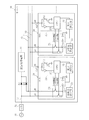
本発明に係る「電子機器」としてのサーバ10は、演算処理装置11、第1受電ライン12、第2受電ライン13、電力供給ライン14、信号ライン15及び複数のバッテリーバックアップユニット20を備えている。
A
演算処理装置11は、サーバ10における各種の演算処理機能を実現する処理装置である。
The
第1受電ライン12は、外部から所定電圧の直流電力を受電する電力ラインである。より具体的には、商用交流電源31から供給される交流電力が電力変換装置32により所定電圧の直流電力に変換されて第1受電ライン12へ供給される。第1受電ライン12はダイオードD1のアノード端子に接続され、ダイオードD1のカソード端子は演算処理装置11の電源端子に接続されている。つまり外部から第1受電ライン12へ供給される直流電力は、ダイオードD1を通じて演算処理装置11へ供給される。
The first
第2受電ライン13は、後述する複数のバッテリーバックアップユニット20が出力する直流電力を受電する電力ラインである。より具体的には第2受電ライン13は、ダイオードD2のアノード端子に接続されており、複数のバッテリーバックアップユニット20の放電端子26が並列に接続される。ダイオードD2のカソード端子はダイオードD1のカソード端子に接続されている。つまり複数のバッテリーバックアップユニット20の放電端子26から放電される直流電力は、ダイオードD2を通じて演算処理装置11へ供給される。
The second
電力供給ライン14は、外部から供給される直流電力の一部を複数のバッテリーバックアップユニット20へ供給する電力ラインである。より具体的には電力供給ライン14は、第1受電ライン12に接続されており、複数のバッテリーバックアップユニット20の充電端子27が並列に接続される。つまり外部から供給される直流電力の一部は、複数のバッテリーバックアップユニット20の充電端子27を通じて、各バッテリーバックアップユニット20の充電に用いられる。したがってサーバ10からバッテリーバックアップユニット20を取り外すことなく、各バッテリーバックアップユニット20の充電を行うことができる。
The
信号ライン15は、複数のバッテリーバックアップユニット20の信号入出力端子28が並列に接続される。
The
<バッテリーバックアップユニットの構成>
本発明に係るバッテリーバックアップユニット20の構成について、引き続き図1を参照しながら説明する。
<Configuration of battery backup unit>
The configuration of the
「電池ユニット」としてのバッテリーバックアップユニット(BBU:Battery Backup Unit)20は、制御装置21、電池ブロック22、電圧測定部23、スイッチ回路24及び過電流検出部25を備える。
A battery backup unit (BBU) 20 as a “battery unit” includes a
制御装置21は、CPU(Central Processing Unit)211、電界効果トランジスタ212及びバッファ213を含む。より具体的には制御装置21は、CPU211を含む公知のマイコン制御装置であり、CPU211で実行される制御プログラムによって、電池ブロック22の充放電制御機能、その他の各種制御機能を発揮する装置である。電界効果トランジスタ212は、ゲート端子がCPU211の信号出力ポートに接続され、ドレイン端子が信号入出力端子28に接続され、ソース端子がグランドに接続されている。バッファ213は、入力端子が信号入出力端子28に接続され、出力端子がCPU211の信号入力ポートに接続されている。
The
「電池」としての電池ブロック22は、複数のアルカリ二次電池等の二次電池(Secondary Battery)が直列乃至並列に接続されて構成されており、正極端子はスイッチ回路24に接続され、負極端子はグランドに接続されている。
The
電圧測定部23は、電池ブロック22の電池電圧を測定する公知の測定回路である。より具体的には電圧測定部23は、検出した電池ブロック22の電池電圧をデジタル信号に変換してCPU211へ出力する。
The
スイッチ回路24は、電池ブロック22から放電端子26への放電ラインを開閉するスイッチ、充電端子27から電池ブロック22への充電ラインを開閉するスイッチを含む。スイッチ回路24の各スイッチは、例えばトランジスタや電磁リレー等であり、CPU211によって開閉制御される。
The
過電流検出部25は、電池ブロック22から放電端子26への放電ラインに流れる電流を検出し、その放電ラインの電流値が電池ブロック22の定格電流等から予め設定した閾値を越えたときに、その放電ラインを遮断する公知の過電流保護回路である。
The
<バッテリーバックアップユニットの充放電制御>
複数のバッテリーバックアップユニット20の各制御装置21が実行する電池ブロック22の充放電制御について、図2及び図3を参照しながら説明する。
<Charge / discharge control of battery backup unit>
The charge / discharge control of the
図2は、停電検出による電池ブロック22の充放電制御の手順を図示したフローチャートである。
FIG. 2 is a flowchart illustrating the procedure of charge / discharge control of the
まず商用交流電源31が停電中か否かを判定する(ステップS1)。より具体的には、外部又はサーバ10に設けられた停電検出装置(図示せず)が出力する商用交流電源31の停電検出信号が各バッテリーバックアップユニット20へ入力される。制御装置21は、この停電検出装置が出力する停電検出信号から商用交流電源31が停電中か否かを判定する。
First, it is determined whether or not the commercial
商用交流電源31が停電中である場合には(ステップS1でYes)、放電制御を実行する(ステップS2)。より具体的には商用交流電源31が停電中である場合には、電池ブロック22から放電端子26への放電ラインのスイッチが開、充電端子27から電池ブロック22への充電ラインが閉となるようにスイッチ回路24を制御する。それによって電池ブロック22が放電する直流電力は、第2受電ライン13を通じて演算処理装置11へ供給される。
When the commercial
他方、商用交流電源31が停電中でない場合には(ステップS1でNo)、充電制御を実行する(ステップS3)。より具体的には商用交流電源31が停電中でない場合には、電池ブロック22から放電端子26への放電ラインのスイッチが閉、充電端子27から電池ブロック22への充電ラインが開となるようにスイッチ回路24を制御する。それによって外部から電力供給ライン14を通じて供給される直流電力で電池ブロック22が充電される。
On the other hand, when the commercial
図3は、放電制御中における放電停止制御の手順を図示したフローチャートである。当該フローチャートに図示した手順は、放電制御(図2のステップS2)の開始時に起動して実行される手順である。 FIG. 3 is a flowchart illustrating a procedure of discharge stop control during discharge control. The procedure illustrated in the flowchart is a procedure that is started and executed at the start of discharge control (step S2 in FIG. 2).
ここでCPU211は、信号入力ポートの電位がロー(Low)レベルである場合には、内部の放電停止フラグ(sigA)を“0”とし、信号入力ポートの電位がハイ(High)レベルである場合には、その放電停止フラグを“1”とする。そして当該手順の起動時には、初期値として放電停止フラグを“1”とする。より具体的には、電界効果トランジスタ212をオフ制御する。それによって信号入出力端子28がハイインピーダンスとなり、CPU211の信号入力ポートの電位がハイ(High)レベルとなるので、放電停止フラグが“1”となる。
Here, the
初期値として放電停止フラグを“1”(sigA=1)とした後、まず商用交流電源31が停電中か否かを判定する(ステップS11)。つまり放電制御中(図2のステップS2)に商用交流電源31の停電が回復したか否かを判定する。商用交流電源31の停電が回復した場合には(ステップS11でNo)、電池ブロック22からの放電を停止する(ステップS15)。より具体的には放電制御中に商用交流電源31の停電が回復した場合には、電池ブロック22から放電端子26への放電ラインのスイッチが閉となるようにスイッチ回路24を制御する。他方、商用交流電源31が依然として停電中である場合には(ステップS11でYes)、放電停止フラグが“1”(sigA=1)であるか否かを判定する(ステップS12)。
After the discharge stop flag is set to “1” (sigA = 1) as an initial value, it is first determined whether or not the commercial
放電停止フラグが“1”(sigA=1)である場合には(ステップS12でYes)、終止電圧を検出したか否かを判定する(ステップS13)。より具体的には、電圧測定部23が検出する電池ブロック22の電池電圧が終止電圧以下になっているか否かを判定する。電池ブロック22の電池電圧が終止電圧以下になっていない場合には(ステップS13でNo)、ステップS11へ戻る。
When the discharge stop flag is “1” (sigA = 1) (Yes in step S12), it is determined whether or not the end voltage is detected (step S13). More specifically, it is determined whether or not the battery voltage of the
他方、電池ブロック22の電池電圧が終止電圧以下になっている場合には(ステップS13でYes)、放電停止フラグを“0”(sigA=0)とする(ステップS14)。より具体的には、電界効果トランジスタ212をオン制御する。それによって信号入出力端子28がグランド電位(0V)となり、CPU211の信号入力ポートの電位がロー(Low)レベルとなるので、放電停止フラグが“0”となる。すなわち制御装置21は、電池ブロック22の電池電圧が終止電圧になったことを条件として(ステップS13でYes)、信号入出力端子28の電位をグランド電位(所定の電位)に変化させる(ステップS14)。
On the other hand, when the battery voltage of the
ステップS11へ戻り、停電中である場合には(ステップS11でYes)、放電停止フラグが“1”(sigA=1)であるか否かを判定する(ステップS12)。そして放電停止フラグが“0”(sigA=0)である場合には(ステップS12でNo)、電池ブロック22からの放電を停止する(ステップS15)。すなわち制御装置21は、信号入出力端子28の電位がグランド電位に変化したことを検出したことを条件として(ステップS12でNo)、電池ブロック22からの放電を停止する(ステップS15)。
Returning to step S11, if a power failure is occurring (Yes in step S11), it is determined whether or not the discharge stop flag is “1” (sigA = 1) (step S12). If the discharge stop flag is “0” (sigA = 0) (No in step S12), the discharge from the
<複数のバッテリーバックアップユニットの連係動作>
複数のバッテリーバックアップユニット20の連係動作について、図1及び図3を参照しながら説明する。
<Cooperation of multiple battery backup units>
The linking operation of the plurality of
前述したように、複数のバッテリーバックアップユニット20のいずれかにおいて電池ブロック22の電池電圧が終止電圧になると(図3のステップS13でYes)、そのバッテリーバックアップユニット20の制御装置21によって、そのバッテリーバックアップユニット20の信号入出力端子28の電位がグランド電位に変化する(図3のステップS14)。また複数のバッテリーバックアップユニット20の信号入出力端子28は、それぞれ信号ライン15に並列に接続されている(図1)。したがって電池ブロック22の電池電圧が終止電圧になったバッテリーバックアップユニット20において、信号入出力端子28の電位がグランド電位に変化すると、瞬時に信号ライン15の電位がグランド電位になる。それによって全てのバッテリーバックアップユニット20において、信号入出力端子28の電位が瞬時にグランド電位に変化する。
As described above, when the battery voltage of the
そして複数のバッテリーバックアップユニット20の各制御装置21は、信号入出力端子28の電位がグランド電位に変化したことを検出したことを条件として(図3のステップS12でNo)、電池ブロック22からの放電を停止する(図3のステップS15)。それによって複数のバッテリーバックアップユニット20の全てが瞬時に、ほぼ同時に放電停止に至ることになる。
Then, each
すなわち本発明に係るサーバ10は、複数のバッテリーバックアップユニット20のいずれかにおいて電池ブロック22の電池電圧が終止電圧になった場合には、その時点で瞬時に、ほぼ同時に、全てのバッテリーバックアップユニット20が放電停止に至ることになる。それによって複数のバッテリーバックアップユニット20のいずれかの電池ブロック22の電池電圧が終止電圧になったときに、他のバッテリーバックアップユニット20の出力電流が過電流となる虞を低減することができる。
That is, in the
<他の実施例、変形例>
本発明は、上記説明した実施例に特に限定されるものではなく、特許請求の範囲に記載された発明の範囲内で種々の変形が可能であることは言うまでもない。
<Other embodiments and modifications>
The present invention is not particularly limited to the embodiments described above, and it goes without saying that various modifications are possible within the scope of the invention described in the claims.
例えばバッテリーバックアップユニット20において、電池ブロック22の終止電圧を検出した制御装置21が信号入出力端子28の電位をグランド電位に変化させる制御を実行したときに、信号入出力端子28又は信号ライン15に何らかの異常や故障等があると、信号入出力端子28がグランド電位に変化しない可能性がある。そのような事態になると、上記実施例の制御装置21による電池ブロック22の充放電制御(図3)においては、各バッテリーバックアップユニット20からの放電を停止することができない。そのため電池電圧が終止電圧に至った電池ブロック22は、そのまま放電が継続して過放電となる虞が生ずる。このようなことから例えば図3に図示したフローチャートに、電池ブロック22の終止電圧を検出したことを条件として電池ブロック22からの放電を停止する手順をさらに設けてもよい。以下、図4を参照しながら説明する。
For example, in the
図4は、放電制御中における放電停止制御の手順の変形例を図示したフローチャートである。ここで初期値として放電停止フラグを“1”(sigA=1)とする点は、上記説明した実施例と同様である。またステップS21〜ステップS25の各手順の内容については、図3に図示したフローチャートのステップS11〜S15と同じであるため、詳細な説明を省略する。 FIG. 4 is a flowchart illustrating a modified example of the procedure of the discharge stop control during the discharge control. The point that the discharge stop flag is set to “1” (sigA = 1) as an initial value is the same as in the above-described embodiment. Further, the contents of each procedure of steps S21 to S25 are the same as steps S11 to S15 of the flowchart shown in FIG.
図4に図示した変形例のフローチャートは、ステップS24を実行した後の処理の流れが図3に図示したフローチャートと異なる。より具体的には、電池ブロック22の電池電圧が終止電圧以下になっている場合には(ステップS23でYes)、放電停止フラグを“0”(sigA=0)とするとともに(ステップS24)、そのまま電池ブロック22からの放電を停止する制御を実行する(ステップS25)。このように電池ブロック22の電池電圧が終止電圧以下になったことを条件として電池ブロック22からの放電を停止することによって、異常や故障等の何らかの要因で信号ライン15又は信号入出力端子28がグランド電位に変化しなかった場合でも、電池電圧が終止電圧に至った電池ブロック22が過放電となる事態を未然に防止することができる。
The flowchart of the modification shown in FIG. 4 is different from the flowchart shown in FIG. 3 in the flow of processing after step S24 is executed. More specifically, when the battery voltage of the
10 サーバ
11 演算処理装置
12 第1受電ライン
13 第2受電ライン
14 電力供給ライン
15 信号ライン
20 バッテリーバックアップユニット
21 制御装置
22 電池ブロック
23 電圧測定部
24 スイッチ回路
25 過電流検出部
26 放電端子
27 充電端子
28 信号入出力端子
DESCRIPTION OF
Claims (6)
前記電池ユニットの所定の信号入出力端子が並列に接続される信号ラインと、を備え、
前記制御装置は、前記電池の終止電圧を検出したことを条件として、前記所定の信号入出力端子の電位を所定の電位に変化させる手段と、
前記所定の信号入出力端子の電位が前記所定の電位に変化したことを検出したことを条件として、前記電池からの放電を停止する手段と、を含む、ことを特徴とする電子機器。 A plurality of battery units including a battery and a control device for controlling the battery;
A signal line to which predetermined signal input / output terminals of the battery unit are connected in parallel;
The control device is configured to change the potential of the predetermined signal input / output terminal to a predetermined potential on condition that the end voltage of the battery is detected;
Means for stopping discharge from the battery on condition that the potential of the predetermined signal input / output terminal is changed to the predetermined potential.
前記制御装置は、前記電力供給ラインから給電される直流電力で前記電池を充電する手段をさらに含む、ことを特徴とする電子機器。 The electronic device according to claim 1, further comprising a power supply line that supplies power to the plurality of battery units,
The electronic device further includes means for charging the battery with DC power fed from the power supply line.
前記電池を制御する制御装置と、を備え、
前記制御装置は、前記電池の終止電圧を検出したことを条件として、所定の信号入出力端子の電位を所定の電位に変化させる手段と、
前記所定の信号入出力端子の電位が前記所定の電位に変化したことを検出したことを条件として、前記電池からの放電を停止する手段と、を含む、ことを特徴とする電池ユニット。 Battery,
A control device for controlling the battery,
The control device is configured to change a potential of a predetermined signal input / output terminal to a predetermined potential on condition that the end voltage of the battery is detected;
Means for stopping discharge from the battery on condition that it has been detected that the potential of the predetermined signal input / output terminal has changed to the predetermined potential.
Priority Applications (1)
| Application Number | Priority Date | Filing Date | Title |
|---|---|---|---|
| JP2011274657A JP2013126331A (en) | 2011-12-15 | 2011-12-15 | Electronic apparatus and battery unit |
Applications Claiming Priority (1)
| Application Number | Priority Date | Filing Date | Title |
|---|---|---|---|
| JP2011274657A JP2013126331A (en) | 2011-12-15 | 2011-12-15 | Electronic apparatus and battery unit |
Publications (1)
| Publication Number | Publication Date |
|---|---|
| JP2013126331A true JP2013126331A (en) | 2013-06-24 |
Family
ID=48777278
Family Applications (1)
| Application Number | Title | Priority Date | Filing Date |
|---|---|---|---|
| JP2011274657A Pending JP2013126331A (en) | 2011-12-15 | 2011-12-15 | Electronic apparatus and battery unit |
Country Status (1)
| Country | Link |
|---|---|
| JP (1) | JP2013126331A (en) |
Cited By (3)
| Publication number | Priority date | Publication date | Assignee | Title |
|---|---|---|---|---|
| KR101541103B1 (en) * | 2014-01-08 | 2015-07-31 | 주식회사 씨엔에이치시스템 | Dynamic voltage compensation system for compensating instant blackout on massive load |
| WO2017002526A1 (en) * | 2015-06-30 | 2017-01-05 | 株式会社Gsユアサ | Control device, power storage device, power storage system, and control method |
| WO2021241136A1 (en) * | 2020-05-26 | 2021-12-02 | Fdk株式会社 | Backup power supply device |
Citations (3)
| Publication number | Priority date | Publication date | Assignee | Title |
|---|---|---|---|---|
| JP2000116014A (en) * | 1998-10-06 | 2000-04-21 | Hitachi Ltd | Power storing device |
| JP2000294298A (en) * | 1999-04-02 | 2000-10-20 | Nec Mobile Energy Kk | Power supply unit for several battery packs |
| JP2010019791A (en) * | 2008-07-14 | 2010-01-28 | Sanyo Electric Co Ltd | Battery device |
-
2011
- 2011-12-15 JP JP2011274657A patent/JP2013126331A/en active Pending
Patent Citations (3)
| Publication number | Priority date | Publication date | Assignee | Title |
|---|---|---|---|---|
| JP2000116014A (en) * | 1998-10-06 | 2000-04-21 | Hitachi Ltd | Power storing device |
| JP2000294298A (en) * | 1999-04-02 | 2000-10-20 | Nec Mobile Energy Kk | Power supply unit for several battery packs |
| JP2010019791A (en) * | 2008-07-14 | 2010-01-28 | Sanyo Electric Co Ltd | Battery device |
Cited By (7)
| Publication number | Priority date | Publication date | Assignee | Title |
|---|---|---|---|---|
| KR101541103B1 (en) * | 2014-01-08 | 2015-07-31 | 주식회사 씨엔에이치시스템 | Dynamic voltage compensation system for compensating instant blackout on massive load |
| WO2017002526A1 (en) * | 2015-06-30 | 2017-01-05 | 株式会社Gsユアサ | Control device, power storage device, power storage system, and control method |
| KR20180033137A (en) * | 2015-06-30 | 2018-04-02 | 가부시키가이샤 지에스 유아사 | Control device, power storage device, power storage system, and control method |
| JPWO2017002526A1 (en) * | 2015-06-30 | 2018-04-19 | 株式会社Gsユアサ | CONTROL DEVICE, POWER STORAGE DEVICE, STORAGE SYSTEM, MOBILE BODY, BACKUP POWER SUPPLY, AND CONTROL METHOD |
| US10693198B2 (en) | 2015-06-30 | 2020-06-23 | Gs Yuasa International Ltd. | Controller, energy storage apparatus, energy storage system, moving object, backup power supply, and controller method |
| KR102206931B1 (en) | 2015-06-30 | 2021-01-22 | 가부시키가이샤 지에스 유아사 | Control device, power storage device, power storage system, moving object, backup power supply, and control method |
| WO2021241136A1 (en) * | 2020-05-26 | 2021-12-02 | Fdk株式会社 | Backup power supply device |
Similar Documents
| Publication | Publication Date | Title |
|---|---|---|
| US10160325B2 (en) | Vehicle power control method and system for jump-start | |
| JP6228666B2 (en) | Battery system | |
| CN107887659B (en) | Power storage device, power storage system, and method for determining state of power storage device | |
| TWI751229B (en) | Control device, control system, power storage device, and computer readable media | |
| US10090683B2 (en) | Battery management system for controlling an energy storage assembly and method for charging and discharging an energy storage assembly | |
| EP3767731B1 (en) | Battery pack and charging bank | |
| US20130308239A1 (en) | Switching device and breaker control method | |
| EP3534167A1 (en) | Method and device for detecting charging abnormality and power adapter | |
| US9966639B2 (en) | Battery monitoring device | |
| US10097036B2 (en) | Uninterruptible power source device | |
| US9466993B2 (en) | Charge and discharge control circuit having an intermediate terminal disconnection detecting circuit for detecting disconnection with secondary batteries | |
| JP2013192389A (en) | Discharge control system and discharge control method for battery pack | |
| US10177560B2 (en) | Battery monitoring device | |
| CN107399287B (en) | Vehicle power system for boost start | |
| JP2013126331A (en) | Electronic apparatus and battery unit | |
| JP2016208646A (en) | Battery device | |
| CN107785864B (en) | Monitoring unit for monitoring a circuit breaker and circuit breaker comprising such a unit | |
| TW201433044A (en) | Charging and discharging control circuit and battery device | |
| JP6571269B2 (en) | Storage battery device, storage battery device control method, and program | |
| US8819470B2 (en) | Switching device, a switching device control method and a switching device control program | |
| CN104716704B (en) | Battery state monitoring circuit and battery device | |
| JP2015173568A (en) | battery protection circuit and battery pack | |
| JP6323162B2 (en) | Battery monitoring device | |
| JP2013031253A (en) | Charge control device and charge control method for storage battery | |
| WO2013118401A1 (en) | Battery control device |
Legal Events
| Date | Code | Title | Description |
|---|---|---|---|
| A621 | Written request for application examination |
Free format text: JAPANESE INTERMEDIATE CODE: A621 Effective date: 20141014 |
|
| RD02 | Notification of acceptance of power of attorney |
Free format text: JAPANESE INTERMEDIATE CODE: A7422 Effective date: 20141014 |
|
| A711 | Notification of change in applicant |
Free format text: JAPANESE INTERMEDIATE CODE: A712 Effective date: 20141222 |
|
| A977 | Report on retrieval |
Free format text: JAPANESE INTERMEDIATE CODE: A971007 Effective date: 20150604 |
|
| A131 | Notification of reasons for refusal |
Free format text: JAPANESE INTERMEDIATE CODE: A131 Effective date: 20150610 |
|
| A521 | Written amendment |
Free format text: JAPANESE INTERMEDIATE CODE: A523 Effective date: 20150714 |
|
| A02 | Decision of refusal |
Free format text: JAPANESE INTERMEDIATE CODE: A02 Effective date: 20151104 |