JP2013121628A - Power tool - Google Patents
Power tool Download PDFInfo
- Publication number
- JP2013121628A JP2013121628A JP2011270368A JP2011270368A JP2013121628A JP 2013121628 A JP2013121628 A JP 2013121628A JP 2011270368 A JP2011270368 A JP 2011270368A JP 2011270368 A JP2011270368 A JP 2011270368A JP 2013121628 A JP2013121628 A JP 2013121628A
- Authority
- JP
- Japan
- Prior art keywords
- terminal
- terminal plate
- terminal block
- battery pack
- buffer member
- Prior art date
- Legal status (The legal status is an assumption and is not a legal conclusion. Google has not performed a legal analysis and makes no representation as to the accuracy of the status listed.)
- Pending
Links
Images


Classifications
-
- B—PERFORMING OPERATIONS; TRANSPORTING
- B25—HAND TOOLS; PORTABLE POWER-DRIVEN TOOLS; MANIPULATORS
- B25F—COMBINATION OR MULTI-PURPOSE TOOLS NOT OTHERWISE PROVIDED FOR; DETAILS OR COMPONENTS OF PORTABLE POWER-DRIVEN TOOLS NOT PARTICULARLY RELATED TO THE OPERATIONS PERFORMED AND NOT OTHERWISE PROVIDED FOR
- B25F5/00—Details or components of portable power-driven tools not particularly related to the operations performed and not otherwise provided for
- B25F5/006—Vibration damping means
Abstract
Description
この発明は、ハウジングに形成されたバッテリー保持部に、端子板を取り付けた端子台が設けられて、前記端子板をバッテリーパックにスライド装着させる電動工具に関する。 The present invention relates to a power tool in which a terminal block to which a terminal plate is attached is provided in a battery holding portion formed in a housing, and the terminal plate is slidably mounted on a battery pack.
例えば非特許文献1には、前後方向に延びる略円筒形状の本体ハウジングと、この本体ハウジングから下方へ突出するハンドル部と、ハンドル部の先端に設けられたバッテリー保持部とを備えて、このバッテリー保持部にバッテリーパックが着脱可能に装着される電動工具が開示されている。非特許文献1の電動工具ではバッテリー保持部に、端子板を取り付けた端子台が設けられて、バッテリーパックをバッテリー保持部に沿ってスライドさせると、端子板がバッテリーパックに配置された充放電用端子にスライド挿入されるようになっている。
For example, Non-Patent
ところで上記の電動工具では、端子板は端子台にインサート成形されているため、電動工具の運転中に発生した振動が本体ハウジングを通じてバッテリー保持部に伝達されると、この振動が端子台を通じて端子板に伝達されるようになっていた。このため、電動工具の運転中には端子板が振動して、この端子板とバッテリーパックの充放電用端子とが互いに擦れ合うことが原因となって、端子板が溶損することが懸念される。そこで端子板の溶損を抑制するために、バッテリー保持部と端子台との間に緩衝材を介在させることで、前記振動が端子板に伝達されることを低減していた。しかしながら緩衝材を端子台とは独立して設けなければならず、より簡単な構造で端子板の溶損を防ぐことが望まれていた。 By the way, in the power tool described above, since the terminal plate is insert-molded in the terminal block, when vibration generated during operation of the power tool is transmitted to the battery holding part through the main body housing, the vibration is transmitted through the terminal block. It was supposed to be transmitted to. For this reason, the terminal plate vibrates during the operation of the electric power tool, and there is a concern that the terminal plate melts due to the friction between the terminal plate and the charge / discharge terminals of the battery pack. Therefore, in order to suppress melting of the terminal plate, a buffer material is interposed between the battery holding portion and the terminal block, thereby reducing the transmission of the vibration to the terminal plate. However, the cushioning material must be provided independently of the terminal block, and it has been desired to prevent the terminal plate from being melted with a simpler structure.
この他にも振動が端子台に伝達されることを低減するために、バッテリー保持部に設けた端子台を、前記振動に追従して移動させることも行われていたが、前記振動に追従させる機構を、電動工具の種類に応じて個別に設計しなければならず、その結果として電動工具の製造コストが増加することも懸念されていた。 In addition to this, in order to reduce the transmission of vibration to the terminal block, the terminal block provided in the battery holding part was also moved following the vibration. The mechanism must be individually designed according to the type of power tool, and as a result, there is a concern that the manufacturing cost of the power tool increases.
この発明は、このような状況に鑑み提案されたものであって、安価かつ簡単な構造で端子板の溶損を抑制できる電動工具を提供することを目的とする。 The present invention has been proposed in view of such a situation, and an object of the present invention is to provide an electric tool capable of suppressing melting damage of a terminal plate with an inexpensive and simple structure.
請求項1の発明に係る電動工具は、ハウジングに形成されたバッテリー保持部に、端子板を取り付けた端子台が設けられて、前記端子板をバッテリーパックにスライド装着させる電動工具であって、少なくとも前記端子台と前記端子板との間に、緩衝材料を介在させたことを特徴とする。
The electric tool according to the invention of
請求項2の発明は、請求項1において、前記端子板に透孔を形成して、前記端子板は、前記透孔に前記緩衝材料が充填された状態で前記端子台に取り付けられることを特徴とする。 According to a second aspect of the present invention, in the first aspect, a through hole is formed in the terminal plate, and the terminal plate is attached to the terminal block in a state in which the through hole is filled with the buffer material. And
請求項1の発明に係る電動工具によれば、電動工具の運転中に発生する振動が、ハウジングに伝達された場合でも、緩衝材料によって、前記振動が端子台から端子板に伝達されることを低減できる。これにより、端子板とバッテリーパックとが互いに擦れ合うことが抑えられて、端子板の溶損を抑制できる。さらに前記緩衝材料を、少なくとも端子台と端子板との間に介在させるだけでよいため、端子板の溶損を抑制する構造を安価かつ簡単に実現できる。
請求項2の発明によれば、緩衝材料を、端子板の透孔に充填した上で端子台と端子板との間に保持できる。したがって、端子板と緩衝材料とを一体にする強度を高めることができる。
According to the electric tool of the first aspect of the present invention, even when vibration generated during operation of the electric tool is transmitted to the housing, the vibration is transmitted from the terminal block to the terminal plate by the buffer material. Can be reduced. Thereby, it is suppressed that a terminal board and a battery pack mutually rub against each other, and the melting damage of a terminal board can be suppressed. Furthermore, since the buffer material only needs to be interposed at least between the terminal block and the terminal plate, a structure that suppresses melting damage of the terminal plate can be realized inexpensively and easily.
According to the second aspect of the present invention, the buffer material can be held between the terminal block and the terminal plate after filling the through holes of the terminal plate. Therefore, the strength of integrating the terminal board and the buffer material can be increased.
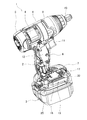
本発明の実施形態を図1ないし図5を参照しつつ説明する。図1及び図2に示すようにインパクトドライバ1は、本体ハウジング2とバッテリーパック3とを備えている。本体ハウジング2は、胴体部4と、リアカバー5と、ハンドル部6と、バッテリー保持部7とを有する。胴体部4は、略円筒状に形成されてインパクトドライバ1の前後方向(図1、2の左右方向)に延設されている。この胴体部4の内部にはモータ8が収容されている。リアカバー5は、胴体部4側を開口させた筒状とされて胴体部4の後端部に取り付けられている。なお、インパクトドライバ1は本発明の電動工具の一例であり、本体ハウジング2は本発明のハウジングの一例である。
An embodiment of the present invention will be described with reference to FIGS. As shown in FIGS. 1 and 2, the
一方胴体部4の前方(図1、2の右方向)には、ハンマケース9が組み付けられている。ハンマケース9の内部には、打撃機構やハンマケース9の先端面から突出するアンビル(図示せず。)が収容されている。アンビルはハンマケース9の内部で回転可能に軸支されて、アンビルの先端には、先端工具やソケットを装着可能なソケット保持部10が設けられている。また前記打撃機構は、モータ8の回転を回転打撃力に変換して前記先端工具や前記ソケットに伝達する。
On the other hand, a
ハンドル部6は、胴体部4から下方へ連設されている。ハンドル部6の内部には、トリガ11を有するスイッチ12が収容されている。バッテリー保持部7は、ハンドル部6の下端に形成されている。バッテリー保持部7の左右の下端には、前後方向に延びるカイドレール(図示せず。)が形成されている。これらのガイドレールは、バッテリーパック3をバッテリー保持部7に装着したときに、後述するバッテリーパック3に設けた左右一対のスライドレール15、15(図1参照。)を外側から挟持する。さらにバッテリー保持部7内で前記スライドレール15、15の間には、端子板16、16を下方へ突設した端子台17(図2及び図3の(c)参照。)が配置されている。
The
図3の(a)に示すように各端子板16は、上下方向の短辺と前後方向の長辺とを有する長方形状で、端子板16、16は、左右方向で互いに対向するように離れて平行に配置されている。各端子板16の上部には、前後方向に並ぶ複数の透孔18が形成されている。さらに両端子板16、16の後端には、左右方向に延びる腕部材19を介して、上下方向に延びて互いに対向する正負の電極20それぞれ連設されている。各腕部材19の中央部と各電極20の下端部にも、透孔18がそれぞれ形成されている。
As shown in FIG. 3A, each
図3の(b)に示すように各端子板16の上端部及び上面部には、二重成形によって、耐熱性及び弾性を備えたエラストマからなる緩衝部材25が一体に形成されている。エラストマを型へ流し込むことにより緩衝部材25は、図4に示すように該エラストマが端子板16の各透孔18に充填された状態で前記上端部の内外面と前記上面部とに一体に形成されている。また図3の(b)に示すように、各腕部材19の表面にも、エラストマが該腕部材19の透孔18に充填された状態で緩衝部材25が一体に形成され、各電極20の下端部及び下面部にも、エラストマが各電極20の透孔18に充填された状態で緩衝部材25が一体に形成されている。腕部材19の緩衝部材25や電極20の緩衝部材25は、端子板16の緩衝部材25と連続して一体に形成されている。なお、エラストマは本発明の緩衝材料の一例である。
As shown in FIG. 3B, a
図3の(c)に示すように樹脂製の端子台17には、二重成形によって、同図の(b)に示すような緩衝部材25をそれぞれ一体に形成した端子板16、16や腕部材19、19が取り付けられる。これにより端子台17の下面には、緩衝部材25を介在させた状態で端子板16、16や腕部材19、19が取り付けられる。電極20、20は、端子台17の上面に開口する電極収容空間26に収容されている。各電極20には、リード線(図示せず。)を介してスイッチ12(図1参照。)が接続されている。
As shown in FIG. 3 (c),
またバッテリーパック3の左右の端部には、前後方向に延びるスライドレール15、15(図1及び図2参照。)が形成されている。さらにバッテリーパック3の内部でスライドレール15、15の間には、端子板16、16同士の間隔と同間隔をおいて充放電用端子31、31(図5参照。)が配置されている。図2に示すようにバッテリーパック3の上面には、充放電用端子31、31同士の間隔と同間隔をおいて前後方向に延びるスリット32、32が形成されている。そして各充放電用端子31は、各スリット32内に臨んでいる。
Further, slide rails 15 and 15 (see FIGS. 1 and 2) extending in the front-rear direction are formed at the left and right ends of the
このバッテリーパック3をバッテリー保持部7に装着する場合には、図2に示すバッテリーパック3のスライドレール15、15を、バッテリー保持部7の左右のガイドレールに沿ってスライドさせる。すると、各ガイドレールが各スライドレール15を挟持してバッテリーパック3がバッテリー保持部7に装着されると共に、図1及び図5に示すように端子板16、16は、スリット32、32に進入することで充放電用端子31、31にスライド挿入される。これにより端子板16、16は、充放電用端子31、31に電気的に接続される。図1に示すトリガ11をハンドル部6内に押し込むことでスイッチ12がオン状態になると、バッテリーパック3はモータ8へ給電する。
When the
例えばソケット保持部10に装着した先端工具によってネジ締めを行うインパクトドライバ1の運転時には、ネジを木材等に締め付けるときの衝撃等に起因して振動が発生する。この振動は、本体ハウジング2から端子台17を通じて端子板16、16へ継続的に伝達されることになる。これにより、端子板16、16が継続的に振動すると、端子板16、16と充放電用端子31、31とが互いに擦れ合う結果、端子板16、16が溶損するという不都合が生じる。これを防止するために本実施形態では、端子台17と端子板16、16との間や、端子台17と腕部材19、19との間にそれぞれ介在させた緩衝部材25で振動を和らげて、振動が端子板16、16に伝達され難い状態を作り出すことができる。したがって、端子板16、16と充放電用端子31、31とが互いに擦れ合うことを抑制できる。加えて、端子板16、16への振動の伝達を抑制するためには、端子台17に上記の緩衝部材25を形成するだけでよく、各充放電用端子31には特別な加工を施す必要がない。よって、各充放電用端子16の構造を簡単にすることが可能である。
For example, when the
<本実施形態の効果>
本実施形態のインパクトドライバ1では、インパクトドライバ1の運転中に発生する振動が、本体ハウジング2に伝達された場合でも、エラストマからなる緩衝部材25によって、前記振動が端子台17から端子板16、16に伝達されることを抑制できる。これにより、端子板16、16とバッテリーパック3の充放電用端子31、31とが互いに擦れ合うことが抑えられて、端子板16、16の溶損を抑制できる。さらに緩衝部材25を、端子台17と端子板16、16との間や端子台17と腕部材19、19との間にそれぞれ介在させるだけでよいため、端子板16、16の溶損を抑制する構造を安価かつ簡単に実現できる。
<Effect of this embodiment>
In the
またエラストマからなる緩衝部材25は、端子板16、16の各透孔18にエラストマを充填した上で端子台17と端子板16、16との間に保持される。したがって、各端子板16と緩衝部材25とを一体にする強度を高めることができる。さらに緩衝部材25は、腕部材19、19の各透孔18にエラストマを充填した上で端子台17と腕部材19、19との間に保持される。したがって、各腕部材19と緩衝部材25とを一体にする強度も高めることができる。
The
本発明は、上述した実施形態に限定されるものではなく、発明の趣旨を逸脱しない範囲内において構成の一部を適宜変更して実施できる。上述した実施形態では、エラストマで緩衝部材25を形成した例を示したが、これとは異なり耐熱性に優れたフッ素ゴムで緩衝部材を形成してもよい。また上述した実施形態では、端子台17の下面に緩衝部材25を介在させた状態で端子板16、16や腕部材19、19が取り付けられた例を示したが、これとは異なり、端子台17の下面に緩衝部材25を介在させて端子板16、16を取り付けるだけで、端子台17の下面と腕部材19、19との間には緩衝部材25を設けなくてもよい。さらに上述した実施形態では本発明を、インパクトドライバに適用する例を示したが、これに限らず、端子板をバッテリーパックにスライド装着させる充電式のドリルドライバ等の電動工具に、本発明を適用してもよい。
The present invention is not limited to the above-described embodiment, and can be implemented by appropriately changing a part of the configuration without departing from the spirit of the invention. In the embodiment described above, an example in which the
1・・インパクトドライバ、2・・本体ハウジング、3・・バッテリーパック、7・・バッテリー保持部、16・・端子板、17・・端子台、18・・透孔、25・・緩衝部材、31・・充放電用端子。 1 .... Impact driver, 2 .... Main body housing, 3 .... Battery pack, 7 .... Battery holding part, 16 .... Terminal plate, 17 .... Terminal block, 18 .... Through hole, 25 ...... Buffer member, 31 ..Charge / discharge terminals.
Claims (2)
少なくとも前記端子台と前記端子板との間に、緩衝材料を介在させたことを特徴とする電動工具。 The battery holder formed in the housing is provided with a terminal block to which a terminal plate is attached, and is an electric tool for slidingly attaching the terminal plate to the battery pack,
A power tool characterized in that a buffer material is interposed between at least the terminal block and the terminal plate.
Priority Applications (4)
| Application Number | Priority Date | Filing Date | Title |
|---|---|---|---|
| JP2011270368A JP2013121628A (en) | 2011-12-09 | 2011-12-09 | Power tool |
| CN2012103857898A CN103158118A (en) | 2011-12-09 | 2012-10-12 | Electric power tool |
| EP12190589.7A EP2602065A2 (en) | 2011-12-09 | 2012-10-30 | Electric power tool |
| US13/665,378 US20130149581A1 (en) | 2011-12-09 | 2012-10-31 | Electric power tool |
Applications Claiming Priority (1)
| Application Number | Priority Date | Filing Date | Title |
|---|---|---|---|
| JP2011270368A JP2013121628A (en) | 2011-12-09 | 2011-12-09 | Power tool |
Publications (2)
| Publication Number | Publication Date |
|---|---|
| JP2013121628A true JP2013121628A (en) | 2013-06-20 |
| JP2013121628A5 JP2013121628A5 (en) | 2014-08-28 |
Family
ID=47146200
Family Applications (1)
| Application Number | Title | Priority Date | Filing Date |
|---|---|---|---|
| JP2011270368A Pending JP2013121628A (en) | 2011-12-09 | 2011-12-09 | Power tool |
Country Status (4)
| Country | Link |
|---|---|
| US (1) | US20130149581A1 (en) |
| EP (1) | EP2602065A2 (en) |
| JP (1) | JP2013121628A (en) |
| CN (1) | CN103158118A (en) |
Cited By (1)
| Publication number | Priority date | Publication date | Assignee | Title |
|---|---|---|---|---|
| JP2015104770A (en) * | 2013-11-29 | 2015-06-08 | 日立工機株式会社 | Power tool |
Families Citing this family (3)
| Publication number | Priority date | Publication date | Assignee | Title |
|---|---|---|---|---|
| JP6085225B2 (en) | 2013-06-27 | 2017-02-22 | 株式会社マキタ | Screw tightening electric tool |
| DE102016201802A1 (en) * | 2015-12-22 | 2017-06-22 | Robert Bosch Gmbh | Hand tool |
| JP6399066B2 (en) | 2016-09-27 | 2018-10-03 | オムロン株式会社 | Trigger switch |
Citations (6)
| Publication number | Priority date | Publication date | Assignee | Title |
|---|---|---|---|---|
| JPH06113705A (en) * | 1992-09-30 | 1994-04-26 | Shuichiro Tashiro | Horseshoe and its production |
| JP3018959U (en) * | 1994-06-10 | 1995-12-05 | ミネソタ マイニング アンド マニュファクチャリング カンパニー | Orthopedic surgical instrument drive and attached battery |
| JPH09223552A (en) * | 1996-02-16 | 1997-08-26 | Yazaki Corp | Movable connector for board and connector terminal |
| JP2001325932A (en) * | 2000-05-16 | 2001-11-22 | Makita Corp | Rechargeable power tool |
| JP2007125691A (en) * | 2005-11-03 | 2007-05-24 | Robert Bosch Gmbh | Power tool machine |
| JP2008302457A (en) * | 2007-06-07 | 2008-12-18 | Makita Corp | Portable type power tool |
Family Cites Families (8)
| Publication number | Priority date | Publication date | Assignee | Title |
|---|---|---|---|---|
| JPH10296660A (en) * | 1997-04-25 | 1998-11-10 | Hitachi Koki Co Ltd | Battery type portable tool |
| JP4269567B2 (en) * | 2002-04-05 | 2009-05-27 | 日立工機株式会社 | Battery tools |
| JP2004147360A (en) * | 2002-10-21 | 2004-05-20 | Makita Corp | Charger |
| JP4981392B2 (en) * | 2006-09-20 | 2012-07-18 | 日立工機株式会社 | Adapter, combination of adapter and battery pack, and electric tool including them |
| JP2010030024A (en) * | 2008-07-31 | 2010-02-12 | Makita Corp | Electric devices |
| CN101502980B (en) * | 2008-09-18 | 2010-08-11 | 虞新华 | Method for producing compound heat preserving building block connected by pin bolt formed using irrigation |
| JP5436850B2 (en) * | 2008-12-19 | 2014-03-05 | 株式会社マキタ | Power tool battery pack |
| US8268478B2 (en) * | 2009-08-17 | 2012-09-18 | Sb Limotive Co., Ltd. | Rechargeable battery having anti-vibration member |
-
2011
- 2011-12-09 JP JP2011270368A patent/JP2013121628A/en active Pending
-
2012
- 2012-10-12 CN CN2012103857898A patent/CN103158118A/en active Pending
- 2012-10-30 EP EP12190589.7A patent/EP2602065A2/en not_active Withdrawn
- 2012-10-31 US US13/665,378 patent/US20130149581A1/en not_active Abandoned
Patent Citations (7)
| Publication number | Priority date | Publication date | Assignee | Title |
|---|---|---|---|---|
| JPH06113705A (en) * | 1992-09-30 | 1994-04-26 | Shuichiro Tashiro | Horseshoe and its production |
| JP3018959U (en) * | 1994-06-10 | 1995-12-05 | ミネソタ マイニング アンド マニュファクチャリング カンパニー | Orthopedic surgical instrument drive and attached battery |
| US5553675A (en) * | 1994-06-10 | 1996-09-10 | Minnesota Mining And Manufacturing Company | Orthopedic surgical device |
| JPH09223552A (en) * | 1996-02-16 | 1997-08-26 | Yazaki Corp | Movable connector for board and connector terminal |
| JP2001325932A (en) * | 2000-05-16 | 2001-11-22 | Makita Corp | Rechargeable power tool |
| JP2007125691A (en) * | 2005-11-03 | 2007-05-24 | Robert Bosch Gmbh | Power tool machine |
| JP2008302457A (en) * | 2007-06-07 | 2008-12-18 | Makita Corp | Portable type power tool |
Cited By (1)
| Publication number | Priority date | Publication date | Assignee | Title |
|---|---|---|---|---|
| JP2015104770A (en) * | 2013-11-29 | 2015-06-08 | 日立工機株式会社 | Power tool |
Also Published As
| Publication number | Publication date |
|---|---|
| US20130149581A1 (en) | 2013-06-13 |
| EP2602065A2 (en) | 2013-06-12 |
| CN103158118A (en) | 2013-06-19 |
Similar Documents
| Publication | Publication Date | Title |
|---|---|---|
| US11148272B2 (en) | Power tool | |
| US10562167B2 (en) | Striking tool | |
| JP4333715B2 (en) | Battery pack, charger, and power tool | |
| JP2013121628A (en) | Power tool | |
| JP4998846B2 (en) | Cordless power tool | |
| GB2432036A (en) | Power Tool | |
| US9876201B2 (en) | Electric working machine and electric working machine system | |
| CN108602219B (en) | Method and apparatus for manufacturing battery pack having fixing structure made of thermoplastic resin | |
| JP2013218931A (en) | Battery pack | |
| JP2007105816A (en) | Battery type power tool | |
| EP3003659A1 (en) | Cordless circular saw | |
| JP2011205872A (en) | Rechargeable battery pack | |
| JP5083630B2 (en) | Battery pack, power tool, charger | |
| JP2018176411A (en) | Impact tool | |
| JP2013121628A5 (en) | ||
| JP2011222171A (en) | Battery for tool | |
| JP2021053751A (en) | Electric tool and battery pack | |
| JP7266214B2 (en) | Power tools and battery packs | |
| CN204886632U (en) | Oscillating motor | |
| JP2012074162A (en) | Battery pack and electric tool provided with the same | |
| KR20120116233A (en) | Electric-powered tool having rechargeable battery | |
| KR102152884B1 (en) | Battery case | |
| JP2019102217A (en) | Battery pack and electric device including the same | |
| JP6364646B2 (en) | Electric tool | |
| WO2021153041A1 (en) | Battery pack and electric tool |
Legal Events
| Date | Code | Title | Description |
|---|---|---|---|
| A521 | Written amendment |
Free format text: JAPANESE INTERMEDIATE CODE: A523 Effective date: 20140710 |
|
| A621 | Written request for application examination |
Free format text: JAPANESE INTERMEDIATE CODE: A621 Effective date: 20140711 |
|
| A977 | Report on retrieval |
Free format text: JAPANESE INTERMEDIATE CODE: A971007 Effective date: 20150317 |
|
| A131 | Notification of reasons for refusal |
Free format text: JAPANESE INTERMEDIATE CODE: A131 Effective date: 20150324 |
|
| A02 | Decision of refusal |
Free format text: JAPANESE INTERMEDIATE CODE: A02 Effective date: 20150804 |