JP2013104916A - Display apparatus and electronic device - Google Patents
Display apparatus and electronic device Download PDFInfo
- Publication number
- JP2013104916A JP2013104916A JP2011246775A JP2011246775A JP2013104916A JP 2013104916 A JP2013104916 A JP 2013104916A JP 2011246775 A JP2011246775 A JP 2011246775A JP 2011246775 A JP2011246775 A JP 2011246775A JP 2013104916 A JP2013104916 A JP 2013104916A
- Authority
- JP
- Japan
- Prior art keywords
- guide plate
- light
- light guide
- display
- display unit
- Prior art date
- Legal status (The legal status is an assumption and is not a legal conclusion. Google has not performed a legal analysis and makes no representation as to the accuracy of the status listed.)
- Abandoned
Links
Images


Classifications
-
- H—ELECTRICITY
- H04—ELECTRIC COMMUNICATION TECHNIQUE
- H04N—PICTORIAL COMMUNICATION, e.g. TELEVISION
- H04N13/00—Stereoscopic video systems; Multi-view video systems; Details thereof
- H04N13/30—Image reproducers
-
- G—PHYSICS
- G02—OPTICS
- G02B—OPTICAL ELEMENTS, SYSTEMS OR APPARATUS
- G02B30/00—Optical systems or apparatus for producing three-dimensional [3D] effects, e.g. stereoscopic images
-
- G—PHYSICS
- G02—OPTICS
- G02B—OPTICAL ELEMENTS, SYSTEMS OR APPARATUS
- G02B30/00—Optical systems or apparatus for producing three-dimensional [3D] effects, e.g. stereoscopic images
- G02B30/20—Optical systems or apparatus for producing three-dimensional [3D] effects, e.g. stereoscopic images by providing first and second parallax images to an observer's left and right eyes
- G02B30/26—Optical systems or apparatus for producing three-dimensional [3D] effects, e.g. stereoscopic images by providing first and second parallax images to an observer's left and right eyes of the autostereoscopic type
- G02B30/27—Optical systems or apparatus for producing three-dimensional [3D] effects, e.g. stereoscopic images by providing first and second parallax images to an observer's left and right eyes of the autostereoscopic type involving lenticular arrays
-
- G—PHYSICS
- G02—OPTICS
- G02B—OPTICAL ELEMENTS, SYSTEMS OR APPARATUS
- G02B30/00—Optical systems or apparatus for producing three-dimensional [3D] effects, e.g. stereoscopic images
- G02B30/20—Optical systems or apparatus for producing three-dimensional [3D] effects, e.g. stereoscopic images by providing first and second parallax images to an observer's left and right eyes
- G02B30/26—Optical systems or apparatus for producing three-dimensional [3D] effects, e.g. stereoscopic images by providing first and second parallax images to an observer's left and right eyes of the autostereoscopic type
- G02B30/30—Optical systems or apparatus for producing three-dimensional [3D] effects, e.g. stereoscopic images by providing first and second parallax images to an observer's left and right eyes of the autostereoscopic type involving parallax barriers
-
- G—PHYSICS
- G02—OPTICS
- G02B—OPTICAL ELEMENTS, SYSTEMS OR APPARATUS
- G02B6/00—Light guides; Structural details of arrangements comprising light guides and other optical elements, e.g. couplings
- G02B6/0001—Light guides; Structural details of arrangements comprising light guides and other optical elements, e.g. couplings specially adapted for lighting devices or systems
- G02B6/0011—Light guides; Structural details of arrangements comprising light guides and other optical elements, e.g. couplings specially adapted for lighting devices or systems the light guides being planar or of plate-like form
-
- G—PHYSICS
- G02—OPTICS
- G02F—OPTICAL DEVICES OR ARRANGEMENTS FOR THE CONTROL OF LIGHT BY MODIFICATION OF THE OPTICAL PROPERTIES OF THE MEDIA OF THE ELEMENTS INVOLVED THEREIN; NON-LINEAR OPTICS; FREQUENCY-CHANGING OF LIGHT; OPTICAL LOGIC ELEMENTS; OPTICAL ANALOGUE/DIGITAL CONVERTERS
- G02F1/00—Devices or arrangements for the control of the intensity, colour, phase, polarisation or direction of light arriving from an independent light source, e.g. switching, gating or modulating; Non-linear optics
- G02F1/01—Devices or arrangements for the control of the intensity, colour, phase, polarisation or direction of light arriving from an independent light source, e.g. switching, gating or modulating; Non-linear optics for the control of the intensity, phase, polarisation or colour
- G02F1/13—Devices or arrangements for the control of the intensity, colour, phase, polarisation or direction of light arriving from an independent light source, e.g. switching, gating or modulating; Non-linear optics for the control of the intensity, phase, polarisation or colour based on liquid crystals, e.g. single liquid crystal display cells
- G02F1/133—Constructional arrangements; Operation of liquid crystal cells; Circuit arrangements
- G02F1/1333—Constructional arrangements; Manufacturing methods
- G02F1/1335—Structural association of cells with optical devices, e.g. polarisers or reflectors
-
- G—PHYSICS
- G09—EDUCATION; CRYPTOGRAPHY; DISPLAY; ADVERTISING; SEALS
- G09F—DISPLAYING; ADVERTISING; SIGNS; LABELS OR NAME-PLATES; SEALS
- G09F9/00—Indicating arrangements for variable information in which the information is built-up on a support by selection or combination of individual elements
-
- H—ELECTRICITY
- H04—ELECTRIC COMMUNICATION TECHNIQUE
- H04N—PICTORIAL COMMUNICATION, e.g. TELEVISION
- H04N13/00—Stereoscopic video systems; Multi-view video systems; Details thereof
- H04N13/30—Image reproducers
- H04N13/302—Image reproducers for viewing without the aid of special glasses, i.e. using autostereoscopic displays
- H04N13/31—Image reproducers for viewing without the aid of special glasses, i.e. using autostereoscopic displays using parallax barriers
- H04N13/312—Image reproducers for viewing without the aid of special glasses, i.e. using autostereoscopic displays using parallax barriers the parallax barriers being placed behind the display panel, e.g. between backlight and spatial light modulator [SLM]
-
- H—ELECTRICITY
- H04—ELECTRIC COMMUNICATION TECHNIQUE
- H04N—PICTORIAL COMMUNICATION, e.g. TELEVISION
- H04N13/00—Stereoscopic video systems; Multi-view video systems; Details thereof
- H04N13/30—Image reproducers
- H04N13/302—Image reproducers for viewing without the aid of special glasses, i.e. using autostereoscopic displays
- H04N13/32—Image reproducers for viewing without the aid of special glasses, i.e. using autostereoscopic displays using arrays of controllable light sources; using moving apertures or moving light sources
-
- H—ELECTRICITY
- H04—ELECTRIC COMMUNICATION TECHNIQUE
- H04N—PICTORIAL COMMUNICATION, e.g. TELEVISION
- H04N13/00—Stereoscopic video systems; Multi-view video systems; Details thereof
- H04N13/30—Image reproducers
- H04N13/356—Image reproducers having separate monoscopic and stereoscopic modes
-
- G—PHYSICS
- G02—OPTICS
- G02B—OPTICAL ELEMENTS, SYSTEMS OR APPARATUS
- G02B6/00—Light guides; Structural details of arrangements comprising light guides and other optical elements, e.g. couplings
- G02B6/0001—Light guides; Structural details of arrangements comprising light guides and other optical elements, e.g. couplings specially adapted for lighting devices or systems
- G02B6/0011—Light guides; Structural details of arrangements comprising light guides and other optical elements, e.g. couplings specially adapted for lighting devices or systems the light guides being planar or of plate-like form
- G02B6/0033—Means for improving the coupling-out of light from the light guide
- G02B6/0035—Means for improving the coupling-out of light from the light guide provided on the surface of the light guide or in the bulk of it
- G02B6/004—Scattering dots or dot-like elements, e.g. microbeads, scattering particles, nanoparticles
- G02B6/0043—Scattering dots or dot-like elements, e.g. microbeads, scattering particles, nanoparticles provided on the surface of the light guide
-
- G—PHYSICS
- G02—OPTICS
- G02F—OPTICAL DEVICES OR ARRANGEMENTS FOR THE CONTROL OF LIGHT BY MODIFICATION OF THE OPTICAL PROPERTIES OF THE MEDIA OF THE ELEMENTS INVOLVED THEREIN; NON-LINEAR OPTICS; FREQUENCY-CHANGING OF LIGHT; OPTICAL LOGIC ELEMENTS; OPTICAL ANALOGUE/DIGITAL CONVERTERS
- G02F1/00—Devices or arrangements for the control of the intensity, colour, phase, polarisation or direction of light arriving from an independent light source, e.g. switching, gating or modulating; Non-linear optics
- G02F1/01—Devices or arrangements for the control of the intensity, colour, phase, polarisation or direction of light arriving from an independent light source, e.g. switching, gating or modulating; Non-linear optics for the control of the intensity, phase, polarisation or colour
- G02F1/13—Devices or arrangements for the control of the intensity, colour, phase, polarisation or direction of light arriving from an independent light source, e.g. switching, gating or modulating; Non-linear optics for the control of the intensity, phase, polarisation or colour based on liquid crystals, e.g. single liquid crystal display cells
- G02F1/133—Constructional arrangements; Operation of liquid crystal cells; Circuit arrangements
- G02F1/1333—Constructional arrangements; Manufacturing methods
- G02F1/1335—Structural association of cells with optical devices, e.g. polarisers or reflectors
- G02F1/1336—Illuminating devices
- G02F1/133626—Illuminating devices providing two modes of illumination, e.g. day-night
Abstract
Description
本開示は、表示装置、その表示装置を備えた電子機器に関する。 The present disclosure relates to a display device and an electronic apparatus including the display device.
近年の表示装置としては、例えばプラズマディスプレイや有機ELディスプレイなどの自発光型の表示装置のほか、例えば液晶ディスプレイなどの非発光型の表示装置が知られている。それらのうちの液晶ディスプレイは、例えば透過型の光変調素子としての液晶パネルと、その液晶パネルに照明光を照射するバックライト装置とを備える。液晶パネルでは、バックライト装置からの照明光の透過率を制御することにより、所定の映像を表示するようになっている。 As display devices in recent years, in addition to self-luminous display devices such as plasma displays and organic EL displays, non-luminous display devices such as liquid crystal displays are known. Among them, the liquid crystal display includes, for example, a liquid crystal panel as a transmissive light modulation element, and a backlight device that irradiates the liquid crystal panel with illumination light. In the liquid crystal panel, a predetermined image is displayed by controlling the transmittance of illumination light from the backlight device.
近年の表示装置に対する薄型化の要請に対応するため、液晶パネルの背後(表示面と反対側)に導光板を配置し、その導光板の端面と対向するようにバックライト装置の光源を配置する構造が既に提案されている(例えば特許文献1,2参照)。
In order to meet the recent demand for thinner display devices, a light guide plate is disposed behind the liquid crystal panel (opposite the display surface), and the light source of the backlight device is disposed so as to face the end surface of the light guide plate. A structure has already been proposed (see, for example,
また、最近では、特殊な眼鏡を装着する必要がなく、裸眼で立体視が可能なパララックスバリア方式を採用した立体表示装置が開発されている。この立体表示装置は、2次元表示パネルの例えば前方(表示面と観察者との間)にパララックスバリアを対向配置したものである。パララックスバリアの一般的な構造は、2次元表示パネルからの表示画像光を遮蔽する遮蔽部と、表示画像光を透過するストライプ状の開口部(スリット部)とを水平方向に交互に設けたものである。 Recently, there has been developed a stereoscopic display device employing a parallax barrier method that does not require wearing special glasses and enables stereoscopic viewing with the naked eye. In this stereoscopic display device, a parallax barrier is disposed oppositely, for example, in front of a two-dimensional display panel (between the display surface and an observer). The general structure of the parallax barrier is provided with shielding portions that shield display image light from the two-dimensional display panel and stripe-shaped openings (slit portions) that transmit display image light alternately in the horizontal direction. Is.
パララックスバリア方式では、2次元表示パネルに立体視用の視差画像(2視点の場合には右眼用視点画像と左眼用視点画像)を空間分割して表示し、その視差画像をパララックスバリアによって水平方向に視差分離することで立体視が行われる。パララックスバリアにおけるスリット幅などを適切に設定することで、所定の位置、方向から観察者が立体表示装置を見た場合に、スリット部を介して観察者の左右の眼に異なる視差画像の光を別々に入射させることができる。 In the parallax barrier method, a parallax image for stereoscopic viewing (a right-eye viewpoint image and a left-eye viewpoint image in the case of two viewpoints) is spatially divided and displayed on a two-dimensional display panel. Stereoscopic viewing is performed by separating the parallax in the horizontal direction by the barrier. By appropriately setting the slit width and the like in the parallax barrier, when the observer views the stereoscopic display device from a predetermined position and direction, light of different parallax images is observed on the left and right eyes of the observer via the slit portion. Can be incident separately.
なお、2次元表示パネルとして例えば透過型の液晶表示パネルを用いる場合、2次元表示パネルの背面側にパララックスバリアを配置する構成も可能である。この場合、パララックスバリアは、透過型の液晶表示パネルとバックライトとの間に配置される。 For example, when a transmissive liquid crystal display panel is used as the two-dimensional display panel, a configuration in which a parallax barrier is disposed on the back side of the two-dimensional display panel is also possible. In this case, the parallax barrier is disposed between the transmissive liquid crystal display panel and the backlight.
しかしながら、上記のようなパララックスバリア方式の立体表示装置では、パララックスバリアという3次元表示用の専用部品を必要とするため、部品点数と配置スペースが通常の2次元表示用の表示装置に比べて多く必要になってしまうという問題がある。 However, a parallax barrier type stereoscopic display device as described above requires a dedicated component for 3D display called a parallax barrier, and thus the number of components and the arrangement space are smaller than those of a normal display device for 2D display. There is a problem that many will be needed.
本開示はかかる問題点に鑑みてなされたもので、その目的は、導光板を用いてパララックスバリアと等価な機能を実現することができ、かつ、高精度の視差画像を形成可能な表示装置および電子機器を提供することにある。 The present disclosure has been made in view of such problems, and an object thereof is to provide a display device that can realize a function equivalent to a parallax barrier using a light guide plate and can form a highly accurate parallax image. And providing electronic equipment.
本開示の表示装置は、導光板を有する照明装置と、その導光板と対向して固着され、導光板からの光を利用して映像表示を行う表示部とを備える。導光板は、互いに対向する第1および第2の内部反射面を有し、第1および第2の内部反射面のうちの少なくとも一方に、外部からの第1の照明光を散乱させて第1の内部反射面から表示部へ向かう散乱光を射出する散乱エリアが複数設けられている。また、本開示の電子機器は、上記表示装置を備えたものである。 The display device according to the present disclosure includes an illumination device having a light guide plate, and a display unit that is fixed to face the light guide plate and performs video display using light from the light guide plate. The light guide plate has first and second internal reflection surfaces facing each other, and scatters the first illumination light from the outside to at least one of the first and second internal reflection surfaces. A plurality of scattering areas for emitting scattered light from the internal reflection surface toward the display unit are provided. An electronic device according to the present disclosure includes the display device.
本開示の表示装置および電子機器では、散乱エリアによって第1の照明光が散乱され、一部またはすべての光が、第1の内部反射面から導光板の外部に射出される。これにより、導光板自体にパララックスバリアとしての機能を持たせることが可能となる。すなわち、等価的に、散乱エリアを開口部(スリット部)としたパララックスバリアとして機能させることができる。さらに、導光板と表示部とが固着されているので、導光板において形成されるパララックスバリアと表示部との相対位置が高い精度で維持される。 In the display device and the electronic apparatus according to the present disclosure, the first illumination light is scattered by the scattering area, and part or all of the light is emitted from the first internal reflection surface to the outside of the light guide plate. As a result, the light guide plate itself can have a function as a parallax barrier. That is, equivalently, it can function as a parallax barrier having the scattering area as an opening (slit). Furthermore, since the light guide plate and the display unit are fixed, the relative position between the parallax barrier formed on the light guide plate and the display unit is maintained with high accuracy.
本開示の表示装置および電子機器によれば、散乱エリアが設けられた導光板自体がパララックスバリアとしての機能を発揮することができる。したがって、別体としてパララックスバリアを設ける場合よりも部品点数を削減でき、薄型化が図れる。さらに、そのような導光板と表示部とが固着した構造により、両者の相対位置精度が向上し、より正確な視差画像を実現することができる。 According to the display device and the electronic apparatus of the present disclosure, the light guide plate itself provided with the scattering area can exhibit a function as a parallax barrier. Therefore, the number of parts can be reduced and the thickness can be reduced as compared with the case where a parallax barrier is provided separately. Further, the structure in which the light guide plate and the display unit are fixed to each other improves the relative positional accuracy between the two, thereby realizing a more accurate parallax image.
以下、本開示の実施の形態について図面を参照して詳細に説明する。 Hereinafter, embodiments of the present disclosure will be described in detail with reference to the drawings.
[表示装置の全体構成]
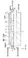
図1から図3は、本開示の一実施の形態に係る表示装置の一構成例を示している。この表示装置は、画像表示を行う表示部1と、表示部1の背面側に配置され、表示部1に向けて画像表示用の光を射出する照明装置とを備えている。照明装置は、第1の光源2(2D/3D表示用光源)と、導光板3と、第2の光源7(2D表示用光源)とを備えている。導光板3は、表示部1と対向して配置される第1の内部反射面3Aと、第2の光源7と対向して配置される第2の内部反射面3Bとを有している。表示部1と導光板3とは、相互に対向するように接着部材4によって固着されている(図1)。ここで、表示部1と導光板3との間には、微小な空間が生じている。但し、図1では、光線の経路を説明するため、その空間の厚さ(すなわち、表示部1と導光板3とのギャップ)を、表示部1や導光板3の厚さに対して相対的に大きく描いている。また、この表示装置は、その他にも、表示に必要な表示部1の制御を行う制御回路等を備えているが、その構成は一般的な表示用の制御回路等と同様であるので、その説明を省略する。また、光源デバイスは、図示しないが、第1の光源2および第2の光源7のオン(点灯)・オフ(非点灯)制御を行う制御回路を備えている。
[Overall configuration of display device]
1 to 3 illustrate a configuration example of a display device according to an embodiment of the present disclosure. The display device includes a
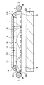
この表示装置は、全画面での2次元(2D)表示モードと、全画面での3次元(3D)表示モードとを任意に選択的に切り替えることが可能とされている。2次元表示モードと3次元表示モードとの切り替えは、表示部1に表示する画像データの切り替え制御と、第1の光源2および第2の光源7のオン・オフの切り替え制御とを行うことで可能となっている。図1は、第1の光源2のみをオン(点灯)状態にした場合における光源デバイスからの光線の射出状態を模式的に示しているが、これは3次元表示モードに対応している。図2は、第2の光源7のみをオン(点灯)状態にした場合における光源デバイスからの光線の射出状態を模式的に示しているが、これは2次元表示モードに対応している。また、図3は、第1の光源2および第2の光源7の双方をオン(点灯)状態にした場合における光源デバイスからの光線の射出状態を模式的に示しているが、これも2次元表示モードに対応している。
This display device can selectively switch between a two-dimensional (2D) display mode on a full screen and a three-dimensional (3D) display mode on a full screen. Switching between the two-dimensional display mode and the three-dimensional display mode is performed by performing switching control of image data displayed on the
表示部1は、透過型の2次元表示パネル、例えば透過型の液晶表示パネルを用いて構成され、例えば図10に示したように、R(赤色)表示用画素11R、G(緑色)表示用画素11G、およびB(青色)表示用画素11Bからなる画素を複数有し、それら複数の画素がマトリクス状に配置されている。表示部1は、光源デバイスからの光を画像データに応じて画素ごとに変調させることで2次元的な画像表示を行うようになっている。表示部1には、3次元画像データに基づく複数の視点画像と2次元画像データに基づく画像とが任意に選択的に切り替え表示されるようになっている。なお、3次元画像データとは、例えば、3次元表示における複数の視野角方向に対応した複数の視点画像を含むデータである。例えば2眼式の3次元表示を行う場合、右眼表示用と左眼表示用の視点画像のデータである。3次元表示モードでの表示を行う場合には、例えば、1画面内にストライプ状の複数の視点画像が含まれる合成画像を生成して表示する。なお、表示部1の各画素に複数の視点画像を割り当てる、その割り当てパターンと散乱エリア31の配置パターンとの対応関係の具体例は後に詳述する。
The
第1の光源2は、例えば、CCFL(Cold Cathode Fluorescent Lamp)等の蛍光ランプや、LED(Light Emitting Diode)を用いて構成されている。第1の光源2は、導光板3内部に向けて側面方向から第1の照明光L1(図1)を照射するようになっている。第1の光源2は、導光板3の側面に少なくとも1つ配置されている。例えば、導光板3の平面形状が四角形である場合、側面は4つとなるが、第1の光源2は、少なくともいずれか1つの側面に配置されていれば良い。図1では、導光板3における互いに対向する2つの側面に第1の光源2を配置した構成例を示している。第1の光源2は、2次元表示モードと3次元表示モードとの切り替えに応じて、オン(点灯)・オフ(非点灯)制御されるようになっている。具体的には第1の光源2は、表示部1に3次元画像データに基づく画像を表示する場合(3次元表示モードの場合)には点灯状態に制御されると共に、表示部1に2次元画像データに基づく画像を表示する場合(2次元表示モードの場合)には非点灯状態(消灯状態)または点灯状態に制御されるようになっている。
The first
第2の光源7は、導光板3に対して第2の内部反射面3Bが形成された側に対向配置されている。第2の光源7は、第2の内部反射面3Bに向けて外側から第2の照明光L10を照射するようになっている(図2、図3参照)。第2の光源7は、一様な面内輝度の光を発する面状光源であれば良く、その構造自体は特定のものには限定されず、市販の面状バックライトを使用することが可能である。例えばCCFLやLED等の発光体と、面内輝度を均一化するための光拡散板とを用いた構造などが考えられる。第2の光源7は、2次元表示モードと3次元表示モードとの切り替えに応じて、オン(点灯)・オフ(非点灯)制御されるようになっている。具体的には第2の光源7は、表示部1に3次元画像データに基づく画像を表示する場合(3次元表示モードの場合)には非点灯状態(消灯状態)に制御されると共に、表示部1に2次元画像データに基づく画像を表示する場合(2次元表示モードの場合)には点灯状態に制御されるようになっている。
The second light source 7 is disposed to face the
導光板3は、例えばアクリル樹脂等による透明なプラスチック板により構成されている。導光板3は、第2の内部反射面3B以外の面は、全面に亘って透明とされている。例えば、導光板3の平面形状が四角形である場合、第1の内部反射面3Aと、4つの側面とが全面に亘って透明とされている。
The
第1の内部反射面3Aは、全面に亘って鏡面加工がなされており、導光板3内部において全反射条件を満たす入射角で入射した光線を内部全反射させると共に、全反射条件から外れた光線を外部に射出するようになっている。
The first
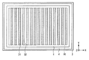
第2の内部反射面3Bは、散乱エリア31と全反射エリア32とを有している。散乱エリア31は、後述するように、導光板3の表面にレーザ加工、サンドブラスト加工、塗装加工、またはシート状の光散乱部材を貼り付けるなどすることで形成されている。第2の内部反射面3Bにおいて、散乱エリア31は3次元表示モードにしたときに、第1の光源2からの第1の照明光L1に対してパララックスバリアとしての開口部(スリット部)として機能し、全反射エリア32は遮蔽部として機能するようになっている。第2の内部反射面3Bにおいて、散乱エリア31と全反射エリア32は、パララックスバリアに相当する構造となるようなパターンで設けられている。すなわち、全反射エリア32はパララックスバリアにおける遮蔽部に相当するパターンで設けられ、散乱エリア31はパララックスバリアにおける開口部に相当するパターンで設けられている。なお、パララックスバリアのバリアパターンとしては例えば、縦長のスリット状の開口部が遮蔽部を介して水平方向に多数、並列配置されたようなストライプ状のパターン等、種々のタイプのものを用いることができ、特定のものには限定されない。
The second
第1の内部反射面3Aと第2の内部反射面3Bにおける全反射エリア32は、全反射条件を満たす入射角θ1で入射した光線を内部全反射させる(所定の臨界角αよりも大きい入射角θ1で入射した光線を内部全反射させる)ようになっている。これにより、全反射条件を満たす入射角θ1で入射した第1の光源2からの第1の照明光L1は、第1の内部反射面3Aと第2の内部反射面3Bにおける全反射エリア32との間で、内部全反射により側面方向に導光されるようになっている。全反射エリア32はまた、図2または図3に示したように、第2の光源7からの第2の照明光L10を透過させ、第1の内部反射面3Aに向けて全反射条件を外れた光線として射出するようになっている。
The
なお、導光板3の屈折率をn1、導光板3の外側の媒質(空気層)の屈折率をn0(<n1)とすると臨界角αは、以下で表される。α,θ1は、導光板表面の法線に対する角度とする。全反射条件を満たす入射角θ1は、θ1>αとなる。
sinα=n0/n1
If the refractive index of the
sin α = n0 / n1
散乱エリア31は、図1に示したように、第1の光源2からの第1の照明光L1を散乱反射させ、第1の照明光L1の少なくとも一部の光を第1の内部反射面3Aに向けて全反射条件を外れた光線(散乱光線L20)として射出するようになっている。
As shown in FIG. 1, the
[接着部材4の構成例]
接着部材4は、例えば紫外線硬化型もしくは熱効果型のエポキシ樹脂からなる接着剤である。接着部材4は、例えば表示部1の周縁部と、導光板3の周縁部とを繋ぐように設けられている。すなわち、導光板3および表示部1は、接着部材4により、有効表示領域1Rを取り囲む周辺領域の全部もしくは一部において固着されている。ここで接着部材4を、例えば図4に示したように有効表示領域1Rを取り囲むように、途切れることなく連続して設けた場合、外部からの水分や異物などの進入が回避されるので好ましい。
[Configuration Example of Adhesive Member 4]
The
また、接着部材4は、可視光を吸収もしくは反射する性質を有するものであることが望ましい。第1の光源2からの第1の照明光L1が、導光板3の第1の内部反射面3Aを透過して接着部材4へ進行したのち、直接的に観察者へ到達し、あるいは表示部1を透過して観察者へ到達する不要光(迷光)となるのを防ぐためである。このような迷光は、表示画像のコントラストを低下させるなどの画質劣化を招くおそれがあり、除去することが望ましい。そのような遮光性の接着部材4は、例えばカーボンブラックを含有する接着剤によって構成する。なお、透明な接着部材4を用いた場合であっても、例えば図5に示した第1の変形例のように、接着部材4と導光板3の対向面3Sとの間に、ブラックマトリックスなどの遮光性の薄膜5を予め設けるようにすればよい。こうした場合であっても、迷光を回避することができる。さらに、接着部材4または薄膜5を、例えばAg(銀)やAl(アルミニウム)などの高反射率を有する材料によって構成すれば、導光板3からの第1の照明光L1を再度、導光板3の内部へ戻すことができ、光の利用効率が向上する。
The
あるいは、透明な接着部材4を用いた場合であっても、その接着部材4が、可視光に対し、導光板3よりも低い屈折率を有するものであればよい。この場合、第1の内部反射面3Aに対する第1の照明光L1の入射角度を、導光板3と接着部材4との間における全反射条件を満たすものとすれば、第1の内部反射面3Aを透過して接着部材4へ進入する迷光が回避されるからである。なお、接着部材4が、導光板3よりも低い屈折率を有し、かつ、透明なものであれば、表示部1と導光板3とによって挟まれた空間を全て満たすように接着部材4を設けることができる。すなわち、表示部1と導光板3とを、有効表示領域1Rを含めて全面的に、かつ、より強固に接着することができる。その場合であっても、第1の内部反射面3Aに対して全反射条件を外れた光線(散乱光線L20)が有効表示領域1Rを透過し表示部1へ向かうことができるので、表示機能は担保される。
Or even if it is a case where the transparent
接着部材4は、例えば表示部1および導光板3における対向面1S,3Sとそれぞれ接すると共に導光板3および表示部1の少なくとも一方の端面(図1では、表示部1の端面1TSと)接するように設けられている。このような構造により、表示部1における有効表示領域1Rをより広く確保しつつ、表示部1と導光板3とをより強固に固着させている。
For example, the
[表示装置の構成の変形例]
図1に示した表示装置において、表示部1に表示された複数の視点画像の空間分離を行うためには、表示部1の画素部と導光板3の散乱エリア31とが所定の距離dを保って対向配置されている必要がある。図1では表示部1と導光板3との間が空気間隔となっているが、図6の第2の変形例に示したように、所定の距離dを保つために、表示部1と導光板3との間にスペーサ8が配置されていても良い。スペーサ8は、無色透明で散乱が少ない材料であればよく、例えばPMMAなどを使用することができる。このスペーサ8は表示部1の背面側の表面と導光板3の表面との全部を覆うように設けられていても良いし、距離dを保つために必要最小限、部分的に設けられていても構わない。
[Modification of display device configuration]
In the display device shown in FIG. 1, in order to perform spatial separation of a plurality of viewpoint images displayed on the
[散乱エリア31の構成例]
図7(A)は、導光板3における第2の内部反射面3Bの第1の構成例を示している。図7(B)は図7(A)に示した第1の構成例における第2の内部反射面3Bでの光線の反射状態および散乱状態を模式的に示している。この第1の構成例は、散乱エリア31を、全反射エリア32に対して凹形状の散乱エリア31Aにした構成例である。このような凹形状の散乱エリア31Aは例えば、サンドブラスト加工やレーザ加工により形成することができる。例えば、導光板3の表面を鏡面加工した後、散乱エリア31Aに対応する部分をレーザ加工することで形成することができる。この第1の構成例の場合、第2の内部反射面3Bにおいて、全反射条件を満たす入射角θ1で入射した第1の光源2からの第1の照明光L11は、全反射エリア32で内部全反射される。一方、凹形状の散乱エリア31Aでは、全反射エリア32と同じ入射角θ1で入射したとしても、入射した第1の照明光L12の光線の一部が凹形状の側面部分33では全反射条件を満たさなくなり、一部が散乱透過し、その他は散乱反射する。この散乱反射した光線(散乱光線L20)の一部またはすべてが、図1に示したように、第1の内部反射面3Aに向けて全反射条件を外れた光線として射出される。
[Configuration Example of Scattering Area 31]
FIG. 7A shows a first configuration example of the second
図8(A)は、導光板3における第2の内部反射面3Bの第2の構成例を示している。図8(B)は図8(A)に示した第2の構成例における第2の内部反射面3Bでの光線の反射状態および散乱状態を模式的に示している。この第2の構成例は、散乱エリア31を、全反射エリア32に対して凸形状の散乱エリア31Bにした構成例である。このような凸形状の散乱エリア31Bは例えば、導光板3の表面を金型による成型加工することで形成することができる。この場合、金型の表面により全反射エリア32に対応する部分については鏡面加工を行う。この第2の構成例の場合、第2の内部反射面3Bにおいて、全反射条件を満たす入射角θ1で入射した第1の光源2からの第1の照明光L11は、全反射エリア32で内部全反射される。一方、凸形状の散乱エリア31Bでは、全反射エリア32と同じ入射角θ1で入射したとしても、入射した第1の照明光L12の光線の一部が凸形状の側面部分34では全反射条件を満たさなくなり、一部が散乱透過し、その他は散乱反射する。この散乱反射した光線(散乱光線L20)の一部またはすべてが、図1に示したように、第1の内部反射面3Aに向けて全反射条件を外れた光線として射出される。
FIG. 8A shows a second configuration example of the second
図9(A)は、導光板3における第2の内部反射面3Bの第3の構成例を示している。図9(B)は図9(A)に示した第3の構成例における第2の内部反射面3Bでの光線の反射状態および散乱状態を模式的に示している。図7(A)および図8(A)の構成例では、導光板3の表面を全反射エリア32とは異なる形状に表面加工することにより散乱エリア31を形成するようにした。これに対して図9(A)の構成例による散乱エリア31Cは、表面加工ではなく、第2の内部反射面3Bに対応する導光板3の表面に、導光板3の材料とは異なる材料による光散乱部材35を配置したものである。この場合、光散乱部材35として例えば白色塗料(例えば硫酸バリウム)をスクリーン印刷で導光板3の表面にパターニングすることで散乱エリア31Cを形成することができる。この第3の構成例の場合、第2の内部反射面3Bにおいて、全反射条件を満たす入射角θ1で入射した第1の光源2からの第1の照明光L11は、全反射エリア32で内部全反射される。一方、光散乱部材35を配置した散乱エリア31Cでは、全反射エリア32と同じ入射角θ1で入射したとしても、入射した第1の照明光L12が光散乱部材35によって一部が散乱透過し、その他は散乱反射する。この散乱反射した光線の一部またはすべてが、第1の内部反射面3Aに向けて全反射条件を外れた光線として射出される。
FIG. 9A shows a third configuration example of the second
[表示装置の基本動作]
この表示装置において、3次元表示モードでの表示を行う場合、表示部1には3次元画像データに基づく画像表示を行うと共に、第1の光源2と第2の光源7とを3次元表示用にオン(点灯)・オフ(非点灯)制御する。具体的には、図1に示したように、第1の光源2をオン(点灯)状態にすると共に、第2の光源7をオフ(非点灯)状態に制御する。この状態では、第1の光源2からの第1の照明光L1は、導光板3において第1の内部反射面3Aと第2の内部反射面3Bの全反射エリア32との間で、繰り返し内部全反射されることにより、第1の光源2が配置された側の一方の側面から、対向する他方の側面へと導光され、他方の側面から射出される。その一方で、第1の光源2による第1の照明光L1の一部が、導光板3の散乱エリア31で散乱反射されることで、導光板3の第1の内部反射面3Aを透過し、導光板3の外部に射出される。これにより、導光板自体にパララックスバリアとしての機能を持たせることが可能となる。すなわち、第1の光源2による第1の照明光L1に対しては、等価的に、散乱エリア31を開口部(スリット部)とし、全反射エリア32を遮蔽部とするようなパララックスバリアとして機能させることができる。これにより、等価的に、表示部1の背面側にパララックスバリアを配置したパララックスバリア方式による3次元表示が行われる。
[Basic operation of display device]
In this display device, when displaying in the three-dimensional display mode, the
一方、2次元表示モードでの表示を行う場合には、表示部1には2次元画像データに基づく画像表示を行うと共に、第1の光源2と第2の光源7とを2次元表示用にオン(点灯)・オフ(非点灯)制御する。具体的には、例えば図2に示したように、第1の光源2をオフ(非点灯)状態にすると共に、第2の光源7をオン(点灯)状態に制御する。この場合、第2の光源7による第2の照明光L10が、第2の内部反射面3Bにおける全反射エリア32を透過することで、第1の内部反射面3Aのほぼ全面から、全反射条件を外れた光線となって導光板3の外部に射出される。すなわち導光板3は、通常のバックライトと同様の面状光源として機能する。これにより、等価的に、表示部1の背面側に通常のバックライトを配置したバックライト方式による2次元表示が行われる。
On the other hand, when performing display in the two-dimensional display mode, the
なお、第2の光源7のみを点灯させたとしても導光板3のほぼ全面から、第2の照明光L10が射出されるが、必要に応じて、図3のように第1の光源2を点灯するようにしても良い。これにより、例えば、第2の光源7のみを点灯しただけでは、散乱エリア31と全反射エリア32とに対応する部分で輝度分布に差が生じるような場合、第1の光源2の点灯状態を適宜調整する(オン・オフ制御、または点灯量の調整をする)ことで全面に亘って輝度分布を最適化することが可能である。ただし、2次元表示を行う場合において、例えば表示部1側で十分に輝度の補正を行える場合には、第2の光源7のみの点灯で構わない。
Even if only the second light source 7 is turned on, the second illumination light L10 is emitted from almost the entire surface of the
[視点画像の割り当てパターンと散乱エリア31の配置パターンとの対応関係]
この表示装置では、3次元表示モードでの表示を行う場合、表示部1には複数の視点画像を所定の割り当てパターンで各画素に割り当てて表示する。導光板3における複数の散乱エリア31は、その所定の割り当てパターンに対応した所定の配置パターンで設けられている。
[Correspondence Relationship between Viewpoint Image Allocation Pattern and
In this display device, when performing display in the three-dimensional display mode, the
以下、視点画像の割り当てパターンと散乱エリア31の配置パターンとの対応関係の具体例を説明する。表示部1の画素構造は、図10に示したように、赤色用画素11R、緑色用画素11G、および青色用画素11Bからなる画素を複数有し、それら複数の画素が第1の方向(垂直方向)および第2の方向(水平方向)にマトリクス状に配置されているものとする。水平方向に3つの色の各画素11R,11G,11Bが周期的に交互に配列され、垂直方向には同一色の各画素11R,11G,11Bが配列されている。この画素構造の場合、表示部1に通常の2次元画像を表示する状態(2次元表示モード)では、水平方向に連続する3つの色の各画素11R,11G,11Bの組み合わせが、2次元のカラー表示を行うための1画素(2Dカラー表示の1単位画素)となる。図10では、2Dカラー表示の1単位画素を、水平方向に6画素分、垂直方向に3画素分、図示している。
Hereinafter, a specific example of the correspondence between the allocation pattern of the viewpoint image and the arrangement pattern of the
図11(A)は図10の画素構造において、表示部1の各画素に2つの視点画像(第1および第2の視点画像)を割り当てた場合の割り当てパターンと散乱エリア31の配置パターンとの対応関係の一例を示している。図11(B)は図11(A)のA−A’部分の断面に相当している。図11(B)では、2つの視点画像の分離状態を模式的に示している。この例では、2Dカラー表示の1単位画素を、1つの視点画像を表示するための1画素として割り当てている。そして、第1の視点画像と第2の視点画像とを水平方向に交互に表示するように画素を割り当てている。従って、2Dカラー表示の1単位画素を水平方向に2つ分、組み合わせたものが、3次元表示としての1単位画像(1立体画素)となる。図11(B)に示したように、第1の視点画像が観察者の右眼10Rのみに到達し、第2の視点画像が観察者の右眼10Rのみに到達する状態となることで、立体視が行われる。この例では、散乱エリア31の水平方向の配置位置が、3次元表示としての1単位画像の略中央部分に位置するように配置されている。
FIG. 11A shows an allocation pattern and an arrangement pattern of the
ここで、散乱エリア31の水平方向の幅D1は、1つの視点画像を表示するための1画素の幅D2に対して所定の関係を有する大きさとされている。具体的には、散乱エリア31の幅D1は、幅D2に対して0.5倍以上1.5倍以下の大きさであることが好ましい。散乱エリア31の幅D1が大きくなるほど、散乱エリア31で散乱される光の量が多くなり、導光板3から射出する光の量が増加する。このため、輝度を増加させることができる。ただし、散乱エリア31の幅D1が、幅D2の1.5倍を超えると、複数の視点画像からの光が混じって観察されてしまう、いわゆるクロストークが生じるので好ましくない。逆に、散乱エリア31の幅D1が小さくなるほど、散乱エリア31で散乱される光の量が少なくなり、導光板3から射出する光の量が減少する。このため、輝度が低減する。散乱エリア31の幅D1が、幅D2の0.5倍を下回ると、輝度が低くなりすぎて画像表示として暗くなりすぎてしまうので、好ましくない。
Here, the horizontal width D1 of the
[効果]
以上説明したように、本実施の形態に係る表示装置によれば、バックライトを構成する導光板3にパララックスバリアとしての機能を持たせるようにした。すなわち、導光板3の散乱エリア31によって第1の照明光L1を散乱させ、一部またはすべての光が第1の内部反射面3Aから表示部1へ向けて射出させるようにした。これにより、導光板3自体が等価的に、散乱エリア31を開口部(スリット部)としたパララックスバリアとして機能することとなる。したがって、別体としてパララックスバリアを設ける場合よりも部品点数を削減でき、薄型化を図ることができる。
[effect]
As described above, according to the display device according to the present embodiment, the
また、本実施の形態では、導光板3と表示部1とを接着部材4によって固着するようにしたので、導光板3において形成されるパララックスバリアと、対応する表示部1の画素11R,11G,11Bとの相対位置が高い精度で維持される。このため導光板3と表示部1との相対位置精度が向上し、より正確な視差画像を実現することができる。
In the present embodiment, since the
また、本実施の形態では、接着部材4を、可視光を吸収もしくは反射する性質を有するものとすれば、接着部材4を透過する不要光を防止し、画質の劣化を回避することができる。また、透明な接着部材4を用いた場合であっても、別途、遮光性あるいは光反射性の薄膜5を設けるようにすれば、上記の不要光の発生を防止できる。さらに、接着部材4または薄膜5を高反射率の材料によって構成すれば、第1の光源2からの第1の照明光L1の利用効率を向上させることができる。
In the present embodiment, if the
[適用例]
次に、上記した照明装置を有する表示装置の適用例について説明する。
[Application example]
Next, application examples of the display device having the above-described lighting device will be described.
本技術の表示装置は、各種用途の電子機器に適用可能であり、その電子機器の種類は特に限定されない。この表示装置は、例えば、以下の電子機器に搭載可能である。ただし、以下で説明する電子機器の構成はあくまで一例であるため、その構成は適宜変更可能である。 The display device of the present technology can be applied to electronic devices for various uses, and the type of the electronic device is not particularly limited. This display device can be mounted on, for example, the following electronic devices. However, the configuration of the electronic device described below is merely an example, and the configuration can be changed as appropriate.
図12は、テレビジョン装置の外観構成を表している。このテレビジョン装置は、例えば、表示装置としての映像表示画面部200を備えている。映像表示画面部200は、フロントパネル210およびフィルターガラス220を含むものである。 FIG. 12 illustrates an appearance configuration of the television device. This television apparatus includes, for example, a video display screen unit 200 as a display device. The video display screen unit 200 includes a front panel 210 and a filter glass 220.
本技術の表示装置は、図12に示したテレビジョン装置のほか、例えばタブレット型パーソナルコンピュータ(PC)、ノート型PC、モバイルフォン、デジタルスチルカメラ、ビデオカメラあるいはカーナビゲーションシステムにおける映像表示部分として用いることができる。 The display device of the present technology is used as a video display portion in, for example, a tablet personal computer (PC), a notebook PC, a mobile phone, a digital still camera, a video camera, or a car navigation system in addition to the television device shown in FIG. be able to.
以上、実施の形態および変形例を挙げて本技術を説明したが、本技術はこれらの実施の形態等には限定されず、種々の変形が可能である。例えば上記実施の形態等では、接着部材4として、接着剤によって導光板3と表示部1とを接着する場合について説明したがこれに限定されるものではない。例えば、Alなどからなる反射テープの両面に接着剤を塗布したものにより、導光板と表示部とを固着させてもよい。
As described above, the present technology has been described with the embodiment and the modified examples, but the present technology is not limited to the embodiment and the like, and various modifications are possible. For example, in the above-described embodiment and the like, the case where the
また、上記実施の形態等では、接着部材4を、表示部1の有効表示領域1Rを取り囲むように連続して設けるようにしたが、これに限定されるものではない。例えば図13に示した第3の変形例のように、表示部1の周縁部に離散的に設けられた4つの接着部材4A〜4Dにより、表示部1と導光板3とを局所的に固着するようにしてもよい。なお、接着部材の配置箇所は図13に示した例に限定されるものではなく、適宜変更可能である。
Moreover, in the said embodiment etc., although the
また、本技術は以下のような構成を取り得るものである。
(1)
導光板を有する照明装置と、
前記導光板と対向して固着され、前記導光板からの光を利用して映像表示を行う表示部と
を備え、
前記導光板は、互いに対向する第1および第2の内部反射面を有し、
前記第1および第2の内部反射面のうちの少なくとも一方に、外部からの第1の照明光を散乱させて前記第1の内部反射面から前記表示部へ向かう散乱光を射出する散乱エリアが複数設けられている
表示装置。
(2)
前記照明装置は、前記導光板の内部へ向けて前記第1の照明光を照射する第1の光源と、前記導光板の前記第2の内部反射面に向けて外側から第2の照明光を照射する第2の光源とを有し、
前記表示部は、3次元画像データに基づく画像と2次元画像データに基づく画像とを選択的に切り替え表示するものであり、
前記第1の光源は、前記表示部に3次元画像データに基づく画像を表示する場合には点灯状態に制御されると共に、前記表示部に2次元画像データに基づく画像を表示する場合には非点灯状態または点灯状態に制御され、
前記第2の光源は、前記表示部に3次元画像データに基づく画像を表示する場合には非点灯状態に制御されると共に、前記表示部に2次元画像データに基づく画像を表示する場合には点灯状態に制御される
上記(1)記載の表示装置。
(3)
前記導光板および表示部は、可視光を吸収もしくは反射する接着部材によって固着されている
上記(1)または(2)に記載の表示装置。
(4)
前記導光板および表示部は、有効表示領域を取り囲む周辺領域の全部もしくは一部において固着されている
上記(1)から(3)のいずれか1つに記載の表示装置。
(5)
前記導光板および表示部は、前記導光板よりも屈折率が低い材料からなる接着部材によって固着されている
上記(1)から(4)のいずれか1つに記載の表示装置。
(6)
前記導光板と前記表示部との間に透光性のスペーサを有する
上記(1)から(5)のいずれか1つに記載の表示装置。
(7)
前記導光板および表示部は、それぞれの対向面と接すると共に前記導光板および表示部の少なくとも一方の端面とも接する接着部材によって固着されている
上記(1)から(6)のいずれか1つに記載の表示装置。
(8)
表示装置を備えた電子機器であって、
前記表示装置は、
導光板を有する照明装置と、
前記導光板と固着され、前記導光板からの光を利用して映像表示を行う表示部と
を含み、
前記導光板は、互いに対向する第1および第2の内部反射面を有し、
前記第1および第2の内部反射面のうちの少なくとも一方に、外部からの第1の照明光を散乱させて前記第1の内部反射面から前記表示部へ向かう散乱光を射出する散乱エリアが複数設けられている
電子機器。
Moreover, this technique can take the following structures.
(1)
A lighting device having a light guide plate;
A display unit fixed to face the light guide plate and performing video display using light from the light guide plate;
The light guide plate has first and second internal reflection surfaces facing each other,
At least one of the first and second internal reflection surfaces has a scattering area that scatters the first illumination light from the outside and emits the scattered light from the first internal reflection surface toward the display unit. Multiple display devices.
(2)
The illumination device has a first light source that irradiates the first illumination light toward the inside of the light guide plate, and second illumination light from the outside toward the second internal reflection surface of the light guide plate. A second light source for irradiation,
The display unit selectively displays an image based on 3D image data and an image based on 2D image data.
The first light source is controlled to be in a lighting state when displaying an image based on three-dimensional image data on the display unit, and is not used when displaying an image based on two-dimensional image data on the display unit. Controlled by lighting state or lighting state,
The second light source is controlled to be in a non-lighting state when displaying an image based on three-dimensional image data on the display unit, and when displaying an image based on two-dimensional image data on the display unit. The display device according to (1), which is controlled to be in a lighting state.
(3)
The display device according to (1) or (2), wherein the light guide plate and the display unit are fixed by an adhesive member that absorbs or reflects visible light.
(4)
The display device according to any one of (1) to (3), wherein the light guide plate and the display unit are fixed in all or a part of a peripheral region surrounding the effective display region.
(5)
The display device according to any one of (1) to (4), wherein the light guide plate and the display unit are fixed by an adhesive member made of a material having a refractive index lower than that of the light guide plate.
(6)
The display device according to any one of (1) to (5), including a light-transmitting spacer between the light guide plate and the display unit.
(7)
The said light guide plate and a display part are adhere | attached by the adhesive member which contact | connects each opposing surface, and also contact | connects at least one end surface of the said light guide plate and a display part. Display device.
(8)
An electronic device provided with a display device,
The display device
A lighting device having a light guide plate;
A display unit fixed to the light guide plate and performing video display using light from the light guide plate;
The light guide plate has first and second internal reflection surfaces facing each other,
At least one of the first and second internal reflection surfaces has a scattering area that scatters the first illumination light from the outside and emits the scattered light from the first internal reflection surface toward the display unit. Multiple electronic devices.
1…表示部、1R…有効表示領域、2…第1の光源(2D/3D表示用光源)、3…導光板、3A…第1の内部反射面、3B…第2の内部反射面、4…接着部材、5…薄膜、7…第2の光源(2D表示用光源)、8…スペーサ、10L…左眼、10R…右眼、11R…赤色表示用画素、11G…緑色表示用画素、11B…青色表示用画素、31…散乱エリア、32…全反射エリア、33…凹形状の側面部分、34…凸形状の側面部分、35…光散乱部材、200…映像表示画面部、210…フロントパネル、220…フィルターガラス、L1,L11,L12…第1の照明光、L10…第2の照明光,L20…散乱光線、θ1…入射角、CP…中心位置。
DESCRIPTION OF
Claims (8)
前記導光板と対向して固着され、前記導光板からの光を利用して映像表示を行う表示部と
を備え、
前記導光板は、互いに対向する第1および第2の内部反射面を有し、
前記第1および第2の内部反射面のうちの少なくとも一方に、外部からの第1の照明光を散乱させて前記第1の内部反射面から前記表示部へ向かう散乱光を射出する散乱エリアが複数設けられている
表示装置。 A lighting device having a light guide plate;
A display unit fixed to face the light guide plate and performing video display using light from the light guide plate;
The light guide plate has first and second internal reflection surfaces facing each other,
At least one of the first and second internal reflection surfaces has a scattering area that scatters the first illumination light from the outside and emits the scattered light from the first internal reflection surface toward the display unit. Multiple display devices.
前記表示部は、3次元画像データに基づく画像と2次元画像データに基づく画像とを選択的に切り替え表示するものであり、
前記第1の光源は、前記表示部に3次元画像データに基づく画像を表示する場合には点灯状態に制御されると共に、前記表示部に2次元画像データに基づく画像を表示する場合には非点灯状態または点灯状態に制御され、
前記第2の光源は、前記表示部に3次元画像データに基づく画像を表示する場合には非点灯状態に制御されると共に、前記表示部に2次元画像データに基づく画像を表示する場合には点灯状態に制御される
請求項1記載の表示装置。 The illumination device has a first light source that irradiates the first illumination light toward the inside of the light guide plate, and second illumination light from the outside toward the second internal reflection surface of the light guide plate. A second light source for irradiation,
The display unit selectively displays an image based on 3D image data and an image based on 2D image data.
The first light source is controlled to be in a lighting state when displaying an image based on three-dimensional image data on the display unit, and is not used when displaying an image based on two-dimensional image data on the display unit. Controlled by lighting state or lighting state,
The second light source is controlled to be in a non-lighting state when displaying an image based on three-dimensional image data on the display unit, and when displaying an image based on two-dimensional image data on the display unit. The display device according to claim 1, wherein the display device is controlled to be in a lighting state.
請求項1記載の表示装置。 The display device according to claim 1, wherein the light guide plate and the display unit are fixed by an adhesive member that absorbs or reflects visible light.
請求項1記載の表示装置。 The display device according to claim 1, wherein the light guide plate and the display unit are fixed in all or a part of a peripheral region surrounding the effective display region.
請求項1記載の表示装置。 The display device according to claim 1, wherein the light guide plate and the display unit are fixed by an adhesive member made of a material having a refractive index lower than that of the light guide plate.
請求項1記載の表示装置。 The display device according to claim 1, further comprising a translucent spacer between the light guide plate and the display unit.
請求項1記載の表示装置。 The display device according to claim 1, wherein the light guide plate and the display unit are fixed by an adhesive member that is in contact with each opposing surface and is also in contact with at least one end surface of the light guide plate and the display unit.
前記表示装置は、
導光板を有する照明装置と、
前記導光板と固着され、前記導光板からの光を利用して映像表示を行う表示部と
を含み、
前記導光板は、互いに対向する第1および第2の内部反射面を有し、
前記第1および第2の内部反射面のうちの少なくとも一方に、外部からの第1の照明光を散乱させて前記第1の内部反射面から前記表示部へ向かう散乱光を射出する散乱エリアが複数設けられている
電子機器。 An electronic device provided with a display device,
The display device
A lighting device having a light guide plate;
A display unit fixed to the light guide plate and performing video display using light from the light guide plate;
The light guide plate has first and second internal reflection surfaces facing each other,
At least one of the first and second internal reflection surfaces has a scattering area that scatters the first illumination light from the outside and emits the scattered light from the first internal reflection surface toward the display unit. Multiple electronic devices.
Priority Applications (6)
| Application Number | Priority Date | Filing Date | Title |
|---|---|---|---|
| JP2011246775A JP2013104916A (en) | 2011-11-10 | 2011-11-10 | Display apparatus and electronic device |
| TW101136081A TW201319623A (en) | 2011-11-10 | 2012-09-28 | Display device and electronic device |
| CN201280053530.1A CN104024923A (en) | 2011-11-10 | 2012-10-12 | Display unit and electronic apparatus |
| KR20147011017A KR20140089523A (en) | 2011-11-10 | 2012-10-12 | Display device and electronic device |
| US14/355,003 US20140300710A1 (en) | 2011-11-10 | 2012-10-12 | Display unit and electronic apparatus |
| PCT/JP2012/076522 WO2013069406A1 (en) | 2011-11-10 | 2012-10-12 | Display device and electronic device |
Applications Claiming Priority (1)
| Application Number | Priority Date | Filing Date | Title |
|---|---|---|---|
| JP2011246775A JP2013104916A (en) | 2011-11-10 | 2011-11-10 | Display apparatus and electronic device |
Publications (2)
| Publication Number | Publication Date |
|---|---|
| JP2013104916A true JP2013104916A (en) | 2013-05-30 |
| JP2013104916A5 JP2013104916A5 (en) | 2014-11-27 |
Family
ID=48289790
Family Applications (1)
| Application Number | Title | Priority Date | Filing Date |
|---|---|---|---|
| JP2011246775A Abandoned JP2013104916A (en) | 2011-11-10 | 2011-11-10 | Display apparatus and electronic device |
Country Status (6)
| Country | Link |
|---|---|
| US (1) | US20140300710A1 (en) |
| JP (1) | JP2013104916A (en) |
| KR (1) | KR20140089523A (en) |
| CN (1) | CN104024923A (en) |
| TW (1) | TW201319623A (en) |
| WO (1) | WO2013069406A1 (en) |
Cited By (2)
| Publication number | Priority date | Publication date | Assignee | Title |
|---|---|---|---|---|
| US9869813B2 (en) | 2014-11-19 | 2018-01-16 | Samsung Electronics Co., Ltd. | Backlight unit, display device comprising the same and method for manufacturing the same |
| US10545280B2 (en) | 2016-01-07 | 2020-01-28 | Samsung Electronics Co., Ltd. | Method of generating directional rays and apparatuses performing the method |
Families Citing this family (9)
| Publication number | Priority date | Publication date | Assignee | Title |
|---|---|---|---|---|
| CN104282225B (en) | 2013-07-01 | 2017-07-14 | 元太科技工业股份有限公司 | Display device |
| US20150185957A1 (en) * | 2013-12-30 | 2015-07-02 | Hannstar Display Corporation | Touch naked eyes stereoscopic display |
| US9804317B2 (en) * | 2015-02-06 | 2017-10-31 | Japan Display Inc. | Display apparatus |
| KR102399552B1 (en) * | 2016-11-28 | 2022-05-18 | 삼성전자주식회사 | Back light unit and display device comprising the same |
| KR20200134226A (en) * | 2018-03-22 | 2020-12-01 | 닛토덴코 가부시키가이샤 | Optical device |
| CN109410760B (en) * | 2018-09-30 | 2021-09-28 | 广州国显科技有限公司 | Flexible display panel, manufacturing method thereof and flexible display device |
| US11420390B2 (en) * | 2018-11-19 | 2022-08-23 | Continuous Composites Inc. | System for additively manufacturing composite structure |
| CN113905872A (en) * | 2019-05-28 | 2022-01-07 | 连续复合材料公司 | System for additive manufacturing of composite structures |
| EP4193203A1 (en) * | 2020-08-06 | 2023-06-14 | Nitto Denko Corporation | Light deflection tape, related method and uses |
Family Cites Families (18)
| Publication number | Priority date | Publication date | Assignee | Title |
|---|---|---|---|---|
| JP3271695B2 (en) * | 1996-09-20 | 2002-04-02 | シャープ株式会社 | Backlight light source and liquid crystal display device |
| JP3391762B2 (en) * | 2000-03-01 | 2003-03-31 | 日本電気株式会社 | Front light unit and liquid crystal display |
| JP2002221722A (en) * | 2001-01-29 | 2002-08-09 | Minolta Co Ltd | Reflective liquid crystal display device |
| JP3776826B2 (en) * | 2002-04-24 | 2006-05-17 | Nec液晶テクノロジー株式会社 | Liquid crystal display |
| TWI264573B (en) * | 2002-11-29 | 2006-10-21 | Hon Hai Prec Ind Co Ltd | Ruler for measuring dots of light guide plate and method of measuring the dots using the ruler |
| WO2004057878A2 (en) * | 2002-12-20 | 2004-07-08 | X3D Technologies Gmbh | Arrangement for two-dimensional or three-dimensional representation |
| GB0322682D0 (en) * | 2003-09-27 | 2003-10-29 | Koninkl Philips Electronics Nv | Backlight for 3D display device |
| EP1774375A1 (en) * | 2004-07-26 | 2007-04-18 | Koninklijke Philips Electronics N.V. | Multi emission mode backlight |
| GB2426351A (en) * | 2005-05-19 | 2006-11-22 | Sharp Kk | A dual view display |
| US8547495B2 (en) * | 2007-06-15 | 2013-10-01 | Lg Display Co., Ltd. | Display device and method for manufacturing thereof |
| KR101493706B1 (en) * | 2008-12-24 | 2015-02-16 | 엘지디스플레이 주식회사 | Backlight unit for liquid crystal display device |
| KR101587551B1 (en) * | 2009-12-17 | 2016-01-21 | 삼성전자주식회사 | 3 3 Waveguide plate for 3D image display and 3D image display apparatus employing the same |
| JP5045826B2 (en) * | 2010-03-31 | 2012-10-10 | ソニー株式会社 | Light source device and stereoscopic display device |
| JP4930631B2 (en) * | 2010-09-27 | 2012-05-16 | ソニー株式会社 | 3D display device |
| TW201224515A (en) * | 2010-12-13 | 2012-06-16 | Ind Tech Res Inst | Display with dimension switchable function |
| KR20120066766A (en) * | 2010-12-15 | 2012-06-25 | 삼성전자주식회사 | Liquid crystal display and driving method threrof |
| KR101866244B1 (en) * | 2011-01-17 | 2018-06-12 | 삼성전자주식회사 | Scanning backlight unit and liquid crystal display having the same |
| JP4973794B1 (en) * | 2011-04-06 | 2012-07-11 | ソニー株式会社 | Display device |
-
2011
- 2011-11-10 JP JP2011246775A patent/JP2013104916A/en not_active Abandoned
-
2012
- 2012-09-28 TW TW101136081A patent/TW201319623A/en unknown
- 2012-10-12 CN CN201280053530.1A patent/CN104024923A/en active Pending
- 2012-10-12 KR KR20147011017A patent/KR20140089523A/en not_active Application Discontinuation
- 2012-10-12 US US14/355,003 patent/US20140300710A1/en not_active Abandoned
- 2012-10-12 WO PCT/JP2012/076522 patent/WO2013069406A1/en active Application Filing
Cited By (2)
| Publication number | Priority date | Publication date | Assignee | Title |
|---|---|---|---|---|
| US9869813B2 (en) | 2014-11-19 | 2018-01-16 | Samsung Electronics Co., Ltd. | Backlight unit, display device comprising the same and method for manufacturing the same |
| US10545280B2 (en) | 2016-01-07 | 2020-01-28 | Samsung Electronics Co., Ltd. | Method of generating directional rays and apparatuses performing the method |
Also Published As
| Publication number | Publication date |
|---|---|
| US20140300710A1 (en) | 2014-10-09 |
| TW201319623A (en) | 2013-05-16 |
| CN104024923A (en) | 2014-09-03 |
| KR20140089523A (en) | 2014-07-15 |
| WO2013069406A1 (en) | 2013-05-16 |
Similar Documents
| Publication | Publication Date | Title |
|---|---|---|
| WO2013069406A1 (en) | Display device and electronic device | |
| JP5045826B2 (en) | Light source device and stereoscopic display device | |
| JP4973794B1 (en) | Display device | |
| JP5674023B2 (en) | Light source device and display device | |
| JP4930631B2 (en) | 3D display device | |
| JP5545068B2 (en) | Light source device and stereoscopic display device | |
| US20120306861A1 (en) | Light source device and display | |
| WO2013069405A1 (en) | Illumination device, display device and electronic device | |
| JP2012237961A (en) | Display device and electronic apparatus | |
| US20140036529A1 (en) | Light source device, display unit, and electronic apparatus | |
| JP2013083904A (en) | Light source device, display device and electronic apparatus | |
| JP2012226294A (en) | Light source device, display, and electronic apparatus | |
| JP2013076725A (en) | Light source device, display apparatus and electronic equipment | |
| JP2012226199A (en) | Light source device and display | |
| JP2013105005A (en) | Light source device, display device, and electronic apparatus | |
| JP2013104915A (en) | Light source device, display device, and electronic apparatus | |
| JP2013104914A (en) | Light source device, display device, and electronic apparatus | |
| JP4720207B2 (en) | Liquid crystal display device | |
| JP2013105675A (en) | Lighting device, display device and electronic equipment | |
| WO2014112258A1 (en) | Display device and electronic device |
Legal Events
| Date | Code | Title | Description |
|---|---|---|---|
| A521 | Request for written amendment filed |
Free format text: JAPANESE INTERMEDIATE CODE: A523 Effective date: 20141015 |
|
| A621 | Written request for application examination |
Free format text: JAPANESE INTERMEDIATE CODE: A621 Effective date: 20141015 |
|
| A762 | Written abandonment of application |
Free format text: JAPANESE INTERMEDIATE CODE: A762 Effective date: 20150406 |