JP2013102325A - Image transmission device, image transmission method, and program - Google Patents
Image transmission device, image transmission method, and program Download PDFInfo
- Publication number
- JP2013102325A JP2013102325A JP2011244352A JP2011244352A JP2013102325A JP 2013102325 A JP2013102325 A JP 2013102325A JP 2011244352 A JP2011244352 A JP 2011244352A JP 2011244352 A JP2011244352 A JP 2011244352A JP 2013102325 A JP2013102325 A JP 2013102325A
- Authority
- JP
- Japan
- Prior art keywords
- display device
- video
- unit
- image
- setting information
- Prior art date
- Legal status (The legal status is an assumption and is not a legal conclusion. Google has not performed a legal analysis and makes no representation as to the accuracy of the status listed.)
- Pending
Links
Images


Classifications
-
- H—ELECTRICITY
- H04—ELECTRIC COMMUNICATION TECHNIQUE
- H04N—PICTORIAL COMMUNICATION, e.g. TELEVISION
- H04N7/00—Television systems
- H04N7/01—Conversion of standards, e.g. involving analogue television standards or digital television standards processed at pixel level
-
- G—PHYSICS
- G09—EDUCATION; CRYPTOGRAPHY; DISPLAY; ADVERTISING; SEALS
- G09G—ARRANGEMENTS OR CIRCUITS FOR CONTROL OF INDICATING DEVICES USING STATIC MEANS TO PRESENT VARIABLE INFORMATION
- G09G5/00—Control arrangements or circuits for visual indicators common to cathode-ray tube indicators and other visual indicators
-
- H—ELECTRICITY
- H04—ELECTRIC COMMUNICATION TECHNIQUE
- H04N—PICTORIAL COMMUNICATION, e.g. TELEVISION
- H04N21/00—Selective content distribution, e.g. interactive television or video on demand [VOD]
- H04N21/40—Client devices specifically adapted for the reception of or interaction with content, e.g. set-top-box [STB]; Operations thereof
- H04N21/41—Structure of client; Structure of client peripherals
- H04N21/4104—Peripherals receiving signals from specially adapted client devices
- H04N21/4122—Peripherals receiving signals from specially adapted client devices additional display device, e.g. video projector
-
- H—ELECTRICITY
- H04—ELECTRIC COMMUNICATION TECHNIQUE
- H04N—PICTORIAL COMMUNICATION, e.g. TELEVISION
- H04N21/00—Selective content distribution, e.g. interactive television or video on demand [VOD]
- H04N21/40—Client devices specifically adapted for the reception of or interaction with content, e.g. set-top-box [STB]; Operations thereof
- H04N21/43—Processing of content or additional data, e.g. demultiplexing additional data from a digital video stream; Elementary client operations, e.g. monitoring of home network or synchronising decoder's clock; Client middleware
- H04N21/436—Interfacing a local distribution network, e.g. communicating with another STB or one or more peripheral devices inside the home
- H04N21/43615—Interfacing a Home Network, e.g. for connecting the client to a plurality of peripherals
-
- H—ELECTRICITY
- H04—ELECTRIC COMMUNICATION TECHNIQUE
- H04N—PICTORIAL COMMUNICATION, e.g. TELEVISION
- H04N21/00—Selective content distribution, e.g. interactive television or video on demand [VOD]
- H04N21/40—Client devices specifically adapted for the reception of or interaction with content, e.g. set-top-box [STB]; Operations thereof
- H04N21/43—Processing of content or additional data, e.g. demultiplexing additional data from a digital video stream; Elementary client operations, e.g. monitoring of home network or synchronising decoder's clock; Client middleware
- H04N21/436—Interfacing a local distribution network, e.g. communicating with another STB or one or more peripheral devices inside the home
- H04N21/4363—Adapting the video or multiplex stream to a specific local network, e.g. a IEEE 1394 or Bluetooth® network
- H04N21/43637—Adapting the video or multiplex stream to a specific local network, e.g. a IEEE 1394 or Bluetooth® network involving a wireless protocol, e.g. Bluetooth, RF or wireless LAN [IEEE 802.11]
-
- H—ELECTRICITY
- H04—ELECTRIC COMMUNICATION TECHNIQUE
- H04N—PICTORIAL COMMUNICATION, e.g. TELEVISION
- H04N21/00—Selective content distribution, e.g. interactive television or video on demand [VOD]
- H04N21/40—Client devices specifically adapted for the reception of or interaction with content, e.g. set-top-box [STB]; Operations thereof
- H04N21/43—Processing of content or additional data, e.g. demultiplexing additional data from a digital video stream; Elementary client operations, e.g. monitoring of home network or synchronising decoder's clock; Client middleware
- H04N21/44—Processing of video elementary streams, e.g. splicing a video clip retrieved from local storage with an incoming video stream, rendering scenes according to MPEG-4 scene graphs
- H04N21/4402—Processing of video elementary streams, e.g. splicing a video clip retrieved from local storage with an incoming video stream, rendering scenes according to MPEG-4 scene graphs involving reformatting operations of video signals for household redistribution, storage or real-time display
-
- G—PHYSICS
- G09—EDUCATION; CRYPTOGRAPHY; DISPLAY; ADVERTISING; SEALS
- G09G—ARRANGEMENTS OR CIRCUITS FOR CONTROL OF INDICATING DEVICES USING STATIC MEANS TO PRESENT VARIABLE INFORMATION
- G09G2340/00—Aspects of display data processing
- G09G2340/04—Changes in size, position or resolution of an image
- G09G2340/0407—Resolution change, inclusive of the use of different resolutions for different screen areas
-
- G—PHYSICS
- G09—EDUCATION; CRYPTOGRAPHY; DISPLAY; ADVERTISING; SEALS
- G09G—ARRANGEMENTS OR CIRCUITS FOR CONTROL OF INDICATING DEVICES USING STATIC MEANS TO PRESENT VARIABLE INFORMATION
- G09G2370/00—Aspects of data communication
- G09G2370/04—Exchange of auxiliary data, i.e. other than image data, between monitor and graphics controller
- G09G2370/042—Exchange of auxiliary data, i.e. other than image data, between monitor and graphics controller for monitor identification
-
- G—PHYSICS
- G09—EDUCATION; CRYPTOGRAPHY; DISPLAY; ADVERTISING; SEALS
- G09G—ARRANGEMENTS OR CIRCUITS FOR CONTROL OF INDICATING DEVICES USING STATIC MEANS TO PRESENT VARIABLE INFORMATION
- G09G2370/00—Aspects of data communication
- G09G2370/16—Use of wireless transmission of display information
Abstract
Description
本発明は、画像送信装置、画像送信方法およびプログラムに関する。 The present invention relates to an image transmission device, an image transmission method, and a program.
従来、複数の映像送信装置から送信される映像を選択して映像受信装置に表示する方法として、映像受信装置と映像送信装置との間に映像信号切替え装置(スイッチャー)を設け、映像信号切替え装置を制御することで映像受信装置に表示する映像を選択する方法が知られている。この方法では、映像受信装置と映像信号切り替え装置、および映像送信装置と映像切り替え装置とをケーブルで接続している。従って、使用する映像受信装置および映像送信装置の台数が増加した場合、ケーブルの配線および映像信号切替え装置の構成が複雑になるという問題があった。また、映像受信装置および映像送信装置のレイアウトの変更も迅速に行うことができないという問題があった。 2. Description of the Related Art Conventionally, as a method for selecting videos transmitted from a plurality of video transmission apparatuses and displaying them on a video reception apparatus, a video signal switching apparatus (switcher) is provided between the video reception apparatus and the video transmission apparatus, and the video signal switching apparatus is provided. There is known a method of selecting a video to be displayed on a video receiving device by controlling. In this method, the video reception device and the video signal switching device, and the video transmission device and the video switching device are connected by a cable. Therefore, when the number of video receiving devices and video transmitting devices to be used increases, there is a problem that the configuration of the cable wiring and the video signal switching device becomes complicated. Further, there has been a problem that the layout of the video receiver and the video transmitter cannot be changed quickly.
近年、無線伝送技術の向上により、映像送信装置から映像受信装置に対してハイビジョン映像を無線で伝送することが可能になった。これにより、映像受信装置と映像送信装置とをケーブルではなく無線通信で接続し、無線接続を切り替えることにより、映像受信装置に表示する映像を選択する方法が可能になった。 In recent years, with the improvement of wireless transmission technology, it has become possible to wirelessly transmit high-definition video from a video transmission device to a video reception device. As a result, it is possible to select a video to be displayed on the video receiving device by connecting the video receiving device and the video transmitting device by wireless communication instead of a cable and switching the wireless connection.
ハイビジョン映像の伝送インターフェースとして、HDMI(High−Definition Multimedia Interface)が知られている。HDMIを用いる映像送信装置は、映像データを伝送する際に、映像受信装置の能力/仕様を示すEDID(Extended Display Identification Data)を読み取ることによって、映像受信装置の能力や仕様に適したフォーマットの映像・音声信号を伝送することができる。 HDMI (High-Definition Multimedia Interface) is known as a high-definition video transmission interface. When transmitting video data, a video transmission device using HDMI reads an EDID (Extended Display Identification Data) indicating the capability / specification of the video reception device, thereby enabling a video in a format suitable for the capability and specification of the video reception device.・ Audio signals can be transmitted.
映像受信装置と映像送信装置との無線接続を切り替えることで映像受信装置に表示する映像を選択する映像システムにおいても、映像送信装置は、映像受信装置の能力や仕様に適したフォーマットの映像・音声信号を送信する必要がある。そこで、映像受信装置は、HDMIで接続されているモニターからEDIDを読み出し、読み出したEDIDを所定のプロトコルで映像送信装置に対して送信する。映像送信装置は、受信したEDIDに基づいて、送信する映像データのフォーマットを映像受信装置が表示可能なフォーマットに変換した後、フォーマット変換後の映像データの送信を開始する。 Even in a video system that selects the video to be displayed on the video receiving device by switching the wireless connection between the video receiving device and the video transmitting device, the video transmitting device has a video / audio format suitable for the capabilities and specifications of the video receiving device. A signal needs to be transmitted. Therefore, the video reception device reads the EDID from a monitor connected via HDMI, and transmits the read EDID to the video transmission device using a predetermined protocol. Based on the received EDID, the video transmission device converts the format of the video data to be transmitted into a format that can be displayed by the video reception device, and then starts transmission of the video data after the format conversion.
図9は、従来知られている映像受信装置と映像送信装置との間のデータの流れを示すシーケンス図である。
(ステップS901)映像受信装置は接続処理を開始する。
(ステップS902)接続処理を開始した映像受信装置は、映像送信装置に対して接続要求メッセージを送信する。
FIG. 9 is a sequence diagram showing a data flow between a conventionally known video receiving apparatus and video transmitting apparatus.
(Step S901) The video receiving apparatus starts a connection process.
(Step S902) The video receiving apparatus that has started the connection process transmits a connection request message to the video transmitting apparatus.
(ステップS903)接続要求メッセージを受信した映像送信装置は、接続処理を開始する。
(ステップS904)接続処理を開始した映像送信装置は、接続要求応答メッセージを映像受信装置に対して送信する。
(ステップS905)映像送信装置は、EDID要求メッセージを映像受信装置に対して送信する。
(Step S903) The video transmitting apparatus that has received the connection request message starts connection processing.
(Step S904) The video transmitting apparatus that has started the connection process transmits a connection request response message to the video receiving apparatus.
(Step S905) The video transmitting apparatus transmits an EDID request message to the video receiving apparatus.
(ステップS906)EDID要求メッセージを受信した映像受信装置は、自装置に接続されているモニターからEDIDを読み出す。
(ステップS907)映像受信装置は、読み出したEDIDを映像送信装置に対して送信する。
(Step S906) Upon receiving the EDID request message, the video reception device reads the EDID from the monitor connected to the device.
(Step S907) The video reception device transmits the read EDID to the video transmission device.
(ステップS908)映像送信装置は、受信したEDIDに基づいて映像データのフォーマットを変換する。
(ステップS909)映像送信装置は、フォーマット変換後の映像データを映像受信装置に対して送信する。
(Step S908) The video transmitting apparatus converts the format of the video data based on the received EDID.
(Step S909) The video transmitting apparatus transmits the video data after the format conversion to the video receiving apparatus.
(ステップS910)映像受信装置は、映像データを受信後、切断要求メッセージを映像送信装置に対して送信する。
ステップS911〜ステップS920の処理は、ステップS901〜ステップS910の処理と同様である。
(Step S910) After receiving the video data, the video reception device transmits a disconnection request message to the video transmission device.
The processing from step S911 to step S920 is the same as the processing from step S901 to step S910.
このように、映像受信装置と映像送信装置とは、接続を行う際にEDIDの送受信を行う。また、一度接続した後切断し再度接続する場合(接続を切り換える場合)においても、映像受信装置と映像送信装置とはEDIDの送受信を行う。 As described above, the video reception device and the video transmission device perform EDID transmission and reception when connecting. Even when the connection is once made and then disconnected and reconnected (when switching the connection), the video reception device and the video transmission device perform EDID transmission / reception.
なお、EDIDはシリアル接続されたEEPROM(Electrically Erasable Programmable Read−Only Memory)に記憶されている。そのため、映像受信装置がEDIDを読み出す際には時間が掛かる。また、映像受信装置から映像送信装置に対してEDIDIを送信するための時間も掛かる。従って、映像受信装置と映像送信装置との無線接続の切り替えに時間が掛かるという問題があった。 The EDID is stored in a serially connected EEPROM (Electrically Erasable Programmable Read-Only Memory). Therefore, it takes time when the video receiving apparatus reads the EDID. In addition, it takes time to transmit EDIDI from the video receiver to the video transmitter. Therefore, there is a problem that it takes time to switch the wireless connection between the video reception device and the video transmission device.
そこで、EDIDの伝送を高速化する方法として、映像受信装置(シンク装置)の第1の記憶手段(EEPROM)に格納されているEDIDを、高速に読み出すことが可能な第2の記憶手段に予め記憶させる。そして、映像受信装置から映像送信装置に対してEDIDを伝送する場合には、第2の記憶手段からEDIDを読み出すことにより、EDIDの伝送を高速化する方法が知られている(例えば、特許文献1参照)。 Therefore, as a method for speeding up the transmission of EDID, the EDID stored in the first storage means (EEPROM) of the video receiving apparatus (sink apparatus) is previously stored in the second storage means that can be read at high speed. Remember. And when transmitting EDID from a video receiver to a video transmitter, there is known a method of speeding up transmission of EDID by reading EDID from a second storage means (for example, Patent Documents). 1).
しかしながら、従来知られている方法では、シリアル接続されたEEPROMからデータを読み出す時間を短縮するこが可能になっているが、読み出したEDIDを映像受信装置から映像送信装置に対して無線送信する時間を短縮することはできず、映像受信装置と映像送信装置との無線接続の切り替えに時間が掛かるという問題があった。 However, in the conventionally known method, it is possible to shorten the time for reading data from the serially connected EEPROM. However, the time for wirelessly transmitting the read EDID from the video receiving apparatus to the video transmitting apparatus. There is a problem that it takes a long time to switch the wireless connection between the video receiver and the video transmitter.
本発明は上記課題を解決するためになされたものであり、映像受信装置と映像送信装置との無線接続の切り替えに掛かる時間をより短縮することができる画像送信装置、画像送信方法およびプログラムを提供することを目的とする。 The present invention has been made to solve the above-described problems, and provides an image transmission device, an image transmission method, and a program capable of further reducing the time required for switching between wireless connection between a video reception device and a video transmission device. The purpose is to do.
本発明は、画像を時系列的に表示する表示部を有する表示装置と無線通信接続を確立してから当該無線通信接続が切断される時点までの間に、当該表示装置に対して前記画像を時系列的に無線送信する通信部と、前記無線通信接続を確立した前記表示装置が有する前記表示部の設定情報に基づいて、当該表示装置に無線送信する前記画像のフォーマットを変更する画像変更部と、前記表示装置を一意に識別する表示装置識別子と、当該表示装置が有する前記表示部の設定情報とを対応付けて記憶する記憶部と、前記表示装置と前記無線通信接続を確立するときに前記記憶部が当該表示装置を一意に識別する前記表示装置識別子と前記設定情報とを対応付けて記憶している場合、当該表示装置に対して前記設定情報の送信要求を行わず、前記記憶部が記憶している前記設定情報に基づいて前記画像変更部に前記画像のフォーマットを変更させ、フォーマットが変更された当該画像を前記通信部に無線送信させる制御部と、を有することを特徴とする画像送信装置である。 According to the present invention, the image is displayed on the display device between the time when the wireless communication connection is disconnected after the wireless communication connection is established with the display device having a display unit that displays the images in time series. A communication unit that wirelessly transmits in time series, and an image change unit that changes the format of the image that is wirelessly transmitted to the display device based on setting information of the display unit included in the display device that has established the wireless communication connection A storage unit that uniquely stores the display device identifier that uniquely identifies the display device, and setting information of the display unit included in the display device, and when establishing the wireless communication connection with the display device When the storage unit stores the display device identifier that uniquely identifies the display device and the setting information in association with each other, the setting information is not transmitted to the display device, and the storage device A control unit that causes the image change unit to change the format of the image based on the setting information stored in the unit, and causes the communication unit to wirelessly transmit the image whose format has been changed. This is an image transmission device.
また、本発明の画像送信装置において、前記制御部は、前記記憶部が当該表示装置を一意に識別する前記表示装置識別子と前記設定情報とを対応付けて記憶していない場合、当該表示装置に対して前記設定情報の送信要求を行うことを特徴とする。 In the image transmission device of the present invention, when the storage unit does not store the display device identifier that uniquely identifies the display device and the setting information in association with each other, the control unit stores the display device in the display device. In contrast, a transmission request for the setting information is made.
また、本発明の画像送信装置において、前記制御部は、前記表示装置と前記無線通信接続を確立するときに前記記憶部が当該表示装置を一意に識別する前記表示装置識別子と前記設定情報とを対応付けて記憶していない場合、当該表示装置に対して前記設定情報の送信要求を行うことを特徴とする。 Further, in the image transmission device of the present invention, the control unit obtains the display device identifier and the setting information for uniquely identifying the display device by the storage unit when establishing the wireless communication connection with the display device. When the information is not stored in association with each other, a transmission request for the setting information is made to the display device.
また、本発明の画像送信装置において、前記制御部は、前記表示装置から前記設定情報を変更したことを示す変更通知情報を前記通信部が受信した場合、当該表示装置に対して前記設定情報の送信要求を行うことを特徴とする。 In the image transmission device of the present invention, when the communication unit receives change notification information indicating that the setting information has been changed from the display device, the control unit transmits the setting information to the display device. A transmission request is performed.
また、本発明の画像送信装置において、前記変更通知情報は、前記前記表示装置から送信される接続要求メッセージに含まれることを特徴とする。 In the image transmission device of the present invention, the change notification information is included in a connection request message transmitted from the display device.
また、本発明は、通信部が、画像を時系列的に表示する表示部を有する表示装置と無線通信接続を確立してから当該無線通信接続が切断される時点までの間に、当該表示装置に対して前記画像を時系列的に無線送信する通信ステップと、画像変更部が、前記無線通信接続を確立した前記表示装置が有する前記表示部の設定情報に基づいて、当該表示装置に無線送信する前記画像のフォーマットを変更する画像変更ステップと、記憶部が、前記表示装置を一意に識別する表示装置識別子と、当該表示装置が有する前記表示部の設定情報とを対応付けて記憶する記憶ステップと、制御部が、前記表示装置と前記無線通信接続を確立するときに前記記憶部が当該表示装置を一意に識別する前記表示装置識別子と前記設定情報とを対応付けて記憶している場合、当該表示装置に対して前記設定情報の送信要求を行わず、前記記憶部が記憶している前記設定情報に基づいて前記画像変更部に前記画像のフォーマットを変更させ、フォーマットが変更された当該画像を前記通信部に無線送信させる制御ステップと、を含むことを特徴とする画像送信方法である。 Further, the present invention provides the display device between the time when the wireless communication connection is disconnected after the communication unit establishes the wireless communication connection with the display device having a display unit that displays images in time series. A communication step of wirelessly transmitting the image in time series, and an image changing unit wirelessly transmitting to the display device based on setting information of the display unit included in the display device that has established the wireless communication connection An image changing step for changing the format of the image, and a storage step in which the storage unit stores a display device identifier for uniquely identifying the display device and setting information of the display unit included in the display device in association with each other. And the control unit stores the display device identifier and the setting information in association with each other when the storage unit uniquely identifies the display device when establishing the wireless communication connection with the display device. The display information is not transmitted to the display device, and the format is changed by causing the image changing unit to change the format of the image based on the setting information stored in the storage unit. And a control step of wirelessly transmitting the image to the communication unit.
また、本発明は、コンピュータを、画像を時系列的に表示する表示部を有する表示装置と無線通信接続を確立してから当該無線通信接続が切断される時点までの間に、当該表示装置に対して前記画像を時系列的に無線送信する通信手段と、前記無線通信接続を確立した前記表示装置が有する前記表示部の設定情報に基づいて、当該表示装置に無線送信する前記画像のフォーマットを変更する画像変更手段と、前記表示装置を一意に識別する表示装置識別子と、当該表示装置が有する前記表示部の設定情報とを対応付けて記憶する記憶手段と、前記表示装置と前記無線通信接続を確立するときに前記記憶手段が当該表示装置を一意に識別する前記表示装置識別子と前記設定情報とを対応付けて記憶している場合、当該表示装置に対して前記設定情報の送信要求を行わず、前記記憶手段が記憶している前記設定情報に基づいて前記画像変更手段に前記画像のフォーマットを変更させ、フォーマットが変更された当該画像を前記通信手段に無線送信させる制御手段と、して機能させるためのプログラムである。 In addition, the present invention relates to a display device between a time when a wireless communication connection is disconnected after establishing a wireless communication connection with a display device having a display unit that displays images in time series. A communication unit that wirelessly transmits the image in time series and a format of the image that is wirelessly transmitted to the display device based on setting information of the display unit included in the display device that has established the wireless communication connection. Image changing means for changing, display device identifier for uniquely identifying the display device, storage means for storing the display unit setting information of the display device in association with each other, the display device and the wireless communication connection When the storage means stores the display device identifier uniquely identifying the display device and the setting information in association with each other, the setting for the display device The image change unit is caused to change the format of the image based on the setting information stored in the storage unit, and the image whose format has been changed is wirelessly transmitted to the communication unit without making a transmission request for information. It is a program for functioning as a control means.
本発明によれば、通信部は、画像を時系列的に表示する表示部を有する表示装置と無線通信接続を確立してから当該無線通信接続が切断される時点までの間に、当該表示装置に対して前記画像を時系列的に無線送信する。また、画像変更部は、無線通信接続を確立した表示装置が有する表示部の設定情報に基づいて、当該表示装置に無線送信する画像のフォーマットを変更する。また、記憶部は、表示装置を一意に識別する表示装置識別子と、当該表示装置が有する表示部の設定情報とを対応付けて記憶する。また、制御部は、表示装置と無線通信接続を確立するときに記憶部が当該表示装置を一意に識別する表示装置識別子と設定情報とを対応付けて記憶している場合、当該表示装置に対して設定情報の送信要求を行わず、記憶部が記憶している設定情報に基づいて画像変更部に画像のフォーマットを変更させ、フォーマットが変更された当該画像を通信部に無線送信させる。 According to the present invention, the communication unit includes the display device between the time when the wireless communication connection is disconnected after the wireless communication connection is established with the display device having the display unit that displays the images in time series. The image is wirelessly transmitted in time series. The image changing unit changes the format of an image to be wirelessly transmitted to the display device based on the setting information of the display unit included in the display device that has established the wireless communication connection. The storage unit stores a display device identifier that uniquely identifies the display device and setting information of the display unit included in the display device in association with each other. In addition, when the control unit stores a display device identifier that uniquely identifies the display device and setting information in association with the display device when establishing a wireless communication connection with the display device, the control unit The image change unit is caused to change the format of the image based on the setting information stored in the storage unit, and the communication unit is caused to wirelessly transmit the image having the changed format.
これにより、表示部の設定情報を取得する処理を省略することができるため、映像受信装置と映像送信装置との無線接続の切り替えに掛かる時間をより短縮することができる。 Thereby, since the process which acquires the setting information of a display part can be abbreviate | omitted, the time concerning switching of the wireless connection of a video receiver and a video transmitter can be shortened more.
(第1の実施形態)
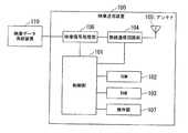
以下、本発明の第1の実施形態について図面を参照して説明する。はじめに、映像送信装置の構成について説明する。図1は、本実施形態における映像送信装置の構成を示したブロック図である。図示する例では、映像送信装置100は、制御部101と、ROM(Read Only Memory)102(記憶部)と、RAM(Random Access Memory)103と、無線通信回路部104(通信部)と、アンテナ105と、映像信号処理部106(画像変更部)と、操作部107とを備えている。また、図示するように、映像送信装置100が備える各部は相互に接続されている。
(First embodiment)
Hereinafter, a first embodiment of the present invention will be described with reference to the drawings. First, the configuration of the video transmission device will be described. FIG. 1 is a block diagram illustrating a configuration of a video transmission apparatus according to the present embodiment. In the illustrated example, the
また、図示する例では、映像送信装置100は、映像データを供給する映像データ供給装置110と接続している。なお、図示する例では、映像データ供給装置110は映像送信装置100とは異なる装置であるが、これに限らない。例えば、映像送信装置100は、映像データ供給装置110を備えていてもよい。
In the illustrated example, the
制御部101は、ROM102に格納されているプログラムに従って動作し、映像送信装置100が備える各部の制御を行う。ROM102はFlashROM(フラッシュロム)等の書き換え可能な不揮発メモリであり、制御部101を動作させるためのプログラムや、接続装置リストや、通信設定パラメータなどの各種設定情報などを記憶する。RAM103は一次記憶メモリであり、制御部101の演算等に使用するワークエリアや、各種設定等を一時的に格納するエリアとして使用される。
The
無線通信回路部104は、アンテナ105を介して他の装置と無線通信を行う。具体的な構成としては、無線通信回路部104は、無線通信に必要な高周波回路部と、符号化・復号化回路部と無線通信時のバッファデータを記憶するバッファメモリ等から構成され、アンテナ105が接続されている。なお、本実施形態では、無線通信回路部104は、IEEE802.11などの所定の無線方式を用いて無線通信を行う。
The wireless
映像信号処理部106は、映像データ供給装置110から入力される映像データの形式を、映像受信装置に接続されているモニター部が表示できる形式に変更する。また、映像信号処理部106は、形式を変更した映像データを所定の方式で圧縮処理し、圧縮した映像データを無線通信回路部104に対して出力する。操作部107は、電源スイッチや、操作スイッチや、設定スイッチ等の複数のスイッチを備え、これらのスイッチの状態及び状態変化を電気信号に変換して制御部101に対して出力する。また、操作部107は、映像受信端末との接続状態および通信状態を報知する複数のLED(Light Emitting Diode)を備えている。
The video
映像データ供給装置110は、ビデオカメラやDVDプレイヤー等の映像データを供給するデバイスであり、HDMIまたはDVI(Digital Visual Interface)等の映像インターフェースを介して映像信号処理部106と接続している。図示する例では映像データ供給装置110と映像送信装置100とは別筐体であり、映像インターフェースを介して接続されているが、上述した通りこれに限らす、映像送信装置100内に映像データ供給装置110を設け、映像データ供給装置110と像信号処理部106とを接続する構成としてもよい。
The video
なお、本発明において、例えば、通信部(通信手段)(例えば、図1の無線通信回路部104)と、画像変更部(画像変更手段)(例えば、図1の映像信号処理部106)と、記憶部(記憶手段)(例えば、図1のROM102)と、制御部(制御手段)(例えば、図1の制御部101)とは必須の構成要件である。
In the present invention, for example, a communication unit (communication unit) (for example, the wireless
次に、映像受信装置の構成について説明する。図2は、本実施形態における映像受信装置の構成を示したブロック図である。図示する例では、映像受信装置200は、制御部201と、ROM202と、RAM203と。無線通信回路部204と、アンテナ205と、映像信号処理部206と、操作部207とを備えている。また、図示するように、映像受信装置200が備える各部は相互に接続されている。
Next, the configuration of the video receiving device will be described. FIG. 2 is a block diagram showing the configuration of the video receiving apparatus in the present embodiment. In the illustrated example, the
また、図示する例では、映像受信装置200は、映像データを表示するモニター部210と接続している。なお、図示する例では、モニター部210は映像受信装置200とは異なる装置であるが、これに限らない。例えば、映像受信装置200はモニター部210を備えていてもよい。
In the illustrated example, the
制御部201は、ROM202に格納されているプログラムに従って動作し、映像受信装置200が備える各部の制御を行う。ROM202はFlashROM等の書き換え可能な不揮発メモリであり、制御部201を動作させるためのプログラムや、通信設定パラメータなどの各種設定情報などを記憶する。RAM203は一次記憶メモリであり、制御部201の演算等に使用するワークエリアや、各種設定等を一時的に格納するエリアとして使用される。
The
無線通信回路部204は、アンテナ205を介して他の装置と無線通信を行う。具体的な構成としては、無線通信回路部204は、無線通信に必要な高周波回路部と、符号化・復号化回路部と無線通信時のバッファデータを記憶するバッファメモリ等から構成され、アンテナ205が接続されている。なお、本実施形態では、無線通信回路部204は、IEEE802.11などの所定の無線方式を用いて無線通信を行う。
The wireless
映像信号処理部206は、無線通信回路部204が受信した、圧縮された映像データを伸張した後、HDMIやNTSC(National Television System Committee)等の映像信号に変換し、モニター部210に対して出力する。操作部207は、電源スイッチや、操作スイッチや、設定スイッチ等の複数のスイッチを備え、これらのスイッチの状態及び状態変化を電気信号に変換して制御部201に対して出力する。また、操作部207は、映像送信装置100との接続状態および通信状態を報知する複数のLEDを備えている。また、操作部207は、映像受信装置200の接続先の映像送信装置100を切り換える際には、モニター部210に表示される映像送信装置100のリストから、接続先として選択する映像送信装置100を指示する入力手段として動作する。
The video
モニター部210は、例えば液晶ディスプレイ等の表示装置である。モニター部210は、液晶表示装置およびその制御回路から構成され、映像送信装置100から送信される映像データの表示を行うとともに、映像受信装置200と映像送信装置100との無線接続の状態を報知する表示手段とし動作する。また、モニター部210は、EDID記憶部を備えている。EDID記憶部211は、モニター部210の能力/仕様を示すEDIDを記憶するメモリである。
The
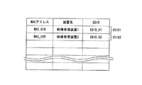
次に、映像送信装置100のROM102が記憶する接続装置リストについて説明する。図3は、本実施形態における映像送信装置100のROM102が記憶する接続装置リストのデータ構造を示した概略図である。接続装置リストは、「MACアドレス(Media Access Control address)」と、「装置名」と、「EDID」とのデータ項目を有しており、各データ項目のデータを行毎に関連付けて記憶する。
Next, the connection device list stored in the
データ項目「MACアドレス」は、映像受信装置200(無線通信回路部204)を一意に特定する情報であるMACアドレスを記憶する。データ項目「装置名」は、同一の行のデータ項目「MACアドレス」に記憶されているMACアドレスで一意に特定される映像受信装置200の装置名を記憶する。データ項目「EDID」は、同一の行のデータ項目「MACアドレス」に記憶されているMACアドレスで一意に特定される映像受信装置200に接続されているモニター部210のEDIDを記憶する。
The data item “MAC address” stores a MAC address that is information for uniquely specifying the video reception device 200 (wireless communication circuit unit 204). The data item “device name” stores the device name of the
図示する例では、行101のデータ項目「MACアドレス」に記憶されている値が「MAC_01R」であり、データ項目「装置名」に記憶されている値が「映像受信装置1」であり、データ項目「EDID」に記憶されている値が「EDID_01」である。これは、MACアドレス「MAC_01」で一意に特定される映像受信装置200の装置名は「映像受信装置1」であり、MACアドレス「MAC_01」で一意に特定される映像受信装置200に接続されているモニター部210のEDIDは「EDID_01」であることを示している。なお、他の行については図示するとおりである。
In the illustrated example, the value stored in the data item “MAC address” in the
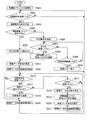
次に、映像送信装置100の動作について説明する。図4は、本実施形態における映像送信装置100の動作手順を示したフローチャートである。
(ステップS301)制御部101は、映像送信装置100の電源が投入された場合、映像送信装置100が備える各部を初期化する。その後、ステップS302の処理に進む。
Next, the operation of the
(Step S301) When the power of the
(ステップS302)映像送信装置100は、映像受信装置200から送信される接続要求メッセージを無線通信回路部104が受信するまで処理を待機する。そして、映像受信装置200から送信される接続要求メッセージを無線通信回路部104が受信した場合、ステップS303の処理に進む。具体的には、無線通信回路部104は、映像受信装置200から接続要求メッセージが送信された場合、この接続要求メッセージを受信する。制御部101は、映像受信装置200から送信される接続要求メッセージを無線通信回路部104が受信したか否かを判定する。そして、接続要求メッセージを受信したと制御部101が判定した場合にはステップS303の処理に進み、それ以外の場合にはステップS302の処理を再度実行する。なお、接続要求メッセージには、接続要求メッセージを送信した映像受信装置200のMACアドレスと装置名とが含まれている。映像送信装置100の制御部101は、接続要求メッセージから、接続要求メッセージを送信した映像受信装置200のMACアドレスと装置名とを取得する。
(Step S302) The
(ステップS303)制御部101は、無線通信回路部104を介して、接続要求応答メッセージを映像受信装置200に対して送信する。その後、ステップS304の処理に進む。ステップS302〜ステップS303の処理を実行することで、映像送信装置100は、映像受信装置200と無線通信接続を確立する。
(Step S <b> 303) The
(ステップS304)制御部101は、ステップS302の処理で取得した、接続要求メッセージを送信した映像受信装置200のMACアドレスが、ROM102が記憶する接続装置リストに含まれているか否かを判定する。接続要求メッセージを送信した映像受信装置200のMACアドレスが接続装置リストに含まれていると制御部101が判定した場合にはステップS305の処理に進み、それ以外の場合にはステップS306の処理に進む。
(Step S304) The
(ステップS305)制御部101は、接続要求メッセージを送信した映像受信装置200のMACアドレスと関連付けて記憶されているEDIDを、ROM102が記憶する接続装置リストから読み出す。その後、ステップS311の処理に進む。
(Step S <b> 305) The
(ステップS306)制御部101は、無線通信回路部104を介して、EDID要求メッセージを映像受信装置200に対して送信する。その後、ステップS307の処理に進む。
(ステップS307)無線通信回路部104は、映像受信装置200に接続されているモニター部210のEDIDが映像受信装置200から送信された場合、このEDIDを受信する。制御部101は、映像受信装置200から送信されるEDIDを無線通信回路部104が受信したか否かを判定する。映像受信装置200に接続されているモニター部210のEDIDを受信したと制御部101が判定した場合にはステップS308の処理に進み、それ以外の場合にはステップS309の処理に進む。
(ステップS308)制御部101は、ステップS302の処理で取得した、接続要求メッセージを送信した映像受信装置200のMACアドレスと装置名と、ステップS307の処理で取得した、接続要求メッセージを送信した映像受信装置200に接続されているモニター部210のEDIDとを関連付けて、ROM102が記憶する接続装置リストに記憶させる。その後、ステップS311の処理に進む。
(Step S <b> 306) The
(Step S307) When the EDID of the
(Step S308) The
(ステップS309)制御部101は、ステップS306の処理でEDID要求メッセージを送信してから所定時間経過したか否かを判定する。ステップS306の処理でEDID要求メッセージを送信してから所定時間経過したと制御部101が判定した場合にはステップS310の処理に進み、それ以外の場合にはステップS307の処理に戻る。なお、所定時間は予め決定していてもよく、任意に設定できるようにしてもよい。
(ステップS310)制御部101は、接続エラー表示を行う。その後、ステップS302の処理に戻る。
(Step S309) The
(Step S310) The
(ステップS311)制御部101は、ステップS305またはステップS307取得した、接続要求メッセージを送信した映像受信装置200に接続されているモニター部210のEDIDに基づいて、送信する映像データの形式(フォーマット)を、このモニター部210が表示することができる形式と決定する。その後、ステップS312の処理に進む。例えば、変更前の映像データの形式は、1920×1080(60Hz)であり、変更後の映像データの形式は、1280×720(60Hz)である。
(Step S311) The
(ステップS312)映像送信装置100は、接続要求メッセージを送信した映像受信装置200に対して、ステップS311の処理で決定した形式に変更した映像データの送信処理を開始する。その後、ステップS313の処理に進む。具体的には、映像信号処理部106は、映像データ供給装置110から映像データを取得し、取得した映像データの形式をステップS311の処理で決定した形式に変更する。また、映像信号処理部106は、形式を変更した映像データを所定の方式で圧縮処理し、圧縮した映像データを無線通信回路部104に対して出力する。無線通信回路部104は、接続要求メッセージを送信した映像受信装置200に対して、映像信号処理部106から入力された映像データを送信する。
(Step S312) The
(ステップS313)無線通信回路部104は、映像受信装置200から切断要求メッセージが送信された場合、この切断要求メッセージを受信する。制御部101は、映像受信装置200から送信される切断要求メッセージを無線通信回路部104が受信したか否かを判定する。切断要求メッセージを受信したと制御部101が判定した場合にはステップS316の処理に進み、それ以外の場合にはステップS314の処理に進む。
(Step S313) When the disconnection request message is transmitted from the
(ステップS314)映像送信装置100のユーザーは、映像データの送信を停止させる場合、操作部107を操作して切断指示を入力する。制御部101は、操作部107が切断指示の入力を受け付けたか否かを判定する。切断指示の入力を受け付けたと制御部101が判定した場合にはステップS315の処理に進み、それ以外の場合にはステップS317の処理に進む。
(Step S314) When stopping transmission of video data, the user of the
(ステップS315)制御部101は、無線通信回路部104を介して、切断要求メッセージを映像受信装置200に対して送信する。その後、ステップS316の処理に進む。
(ステップS316)制御部101は、映像信号処理部106と無線通信回路部104との動作を停止させ、映像データの送信処理を終了させる。その後、ステップS302の処理に戻る。
(Step S <b> 315) The
(Step S316) The
(ステップS317)無線通信回路部104は、映像受信装置200からEDIDが送信された場合、このEDIDを受信する。制御部101は、映像受信装置200から送信されるEDIDを無線通信回路部104が受信したか否かを判定する。EDIDを受信したと制御部101が判定した場合にはステップS318の処理に進み、それ以外の場合にはステップS313の処理に戻る。
(Step S317) When the EDID is transmitted from the
(ステップS318)制御部101は、映像信号処理部106と無線通信回路部104との動作を停止させ、映像データの送信処理を終了させる。その後、ステップS319の処理に進む。
(Step S318) The
(ステップS319)制御部101は、既に記憶されている、ステップS302の処理で取得した、接続要求メッセージを送信した映像受信装置200のMACアドレスと、このMACアドレスと関連付けて記憶されている装置名とEDIDとを、ROM102が記憶する接続装置リストから消去する。その後、制御部101は、ステップS302の処理で取得した、接続要求メッセージを送信した映像受信装置200のMACアドレスと装置名と、ステップS317の処理で取得した、接続要求メッセージを送信した映像受信装置200に接続されているモニター部210のEDIDとを関連付けて、ROM102が記憶する接続装置リストに記憶させる。その後、ステップS320の処理に進む。なお、MACアドレスと装置名とEDIDとを消去し、新たにMACアドレスと装置名とEDIDとを記憶させるのではなく、ステップS317で取得したEDIDを上書きするようにしてもよい。
(Step S319) The
(ステップS320)制御部101は、ステップS317の処理で取得した、接続要求メッセージを送信した映像受信装置200に接続されているモニター部210のEDIDに基づいて、送信する映像データの形式(フォーマット)を、このモニター部210が表示することができる形式と決定する。その後、ステップS321の処理に進む。
(Step S320) The
(ステップS321)映像送信装置100は、接続要求メッセージを送信した映像受信装置200に対して、ステップS320の処理で決定した形式に変更した映像データの送信処理を開始する。その後、ステップS313の処理に戻る。
(Step S321) The
なお、特許請求の範囲に記載の通信ステップは、例えばステップS302,S303,S321の処理に相当する。また、特許請求の範囲に記載の画像変更ステップは、例えばステップS311,S320の処理に相当する。また、特許請求の範囲に記載の記憶ステップは、例えばステップS306〜S308,S317,S319の処理に相当する。また、特許請求の範囲に記載の制御ステップは、例えばステップS304,S305,S312の処理に相当する。また、本発明において、例えば、図4のステップS302〜S308,S311,S312,S317,S319〜S321の処理は必須の構成要件である。 The communication step described in the claims corresponds to, for example, the processes of steps S302, S303, and S321. Further, the image changing step described in the claims corresponds to, for example, the processing of steps S311 and S320. Further, the storage step described in the claims corresponds to, for example, the processing of steps S306 to S308, S317, and S319. Moreover, the control step described in the claims corresponds to, for example, the processes of steps S304, S305, and S312. Further, in the present invention, for example, the processing of steps S302 to S308, S311, S312, S317, and S319 to S321 in FIG.
次に、映像送信装置200の動作について説明する。図5は、本実施形態における映像受信装置200の動作手順を示したフローチャートである。
(ステップS401)制御部101は、映像受信装置200の電源が投入された場合、映像受信装置200が備える各部を初期化する。その後、ステップS402の処理に進む。
Next, the operation of the
(Step S401) When the power of the
(ステップS402)映像受信装置200のユーザーは、映像受信装置200と接続する映像送信装置100を選択する場合、操作部207を操作して接続する映像受信装置200の選択指示を入力する。制御部201は、操作部207が選択指示の入力を受け付けたか否かを判定する。選択指示の入力を受け付けたと制御部201が判定した場合にはステップS403の処理に進み、それ以外の場合にはステップS402の処理を再度実行する。
(Step S402) When the user of the
(ステップS403)制御部201は、無線通信回路部204を介して、ステップS403の処理で操作部207が入力を受け付けた選択指示に基づいて、ユーザーに選択された映像送信装置100に対して接続要求メッセージを送信する。その後、ステップS404の処理に進む。
(ステップS404)無線通信回路部204は、映像送信装置100から接続要求応答メッセージが送信された場合、この接続要求応答メッセージを受信する。制御部201は、映像送信装置100から送信される接続要求応答メッセージを無線通信回路部204が受信したか否かを判定する。接続要求応答メッセージを受信したと制御部201が判定した場合にはステップS407の処理に進み、それ以外の場合にはステップS405の処理に進む。
(Step S403) The
(Step S404) When the connection request response message is transmitted from the
(ステップS405)制御部201は、ステップS403の処理で接続要求メッセージを送信してから所定時間経過したか否かを判定する。ステップS403の処理で接続要求メッセージを送信してから所定時間経過したと制御部201が判定した場合にはステップS406の処理に進み、それ以外の場合にはステップS404の処理に戻る。なお、所定時間は予め決定していてもよく、任意に設定できるようにしてもよい。
(ステップS406)制御部201は、接続エラー表示を行う。その後、ステップS402の処理に戻る。
(Step S405) The
(Step S406) The
(ステップS407)無線通信回路部204は、映像送信装置100からEDID要求メッセージが送信された場合、このEDID要求メッセージを受信する。制御部201は、映像送信装置100から送信されるEDID要求メッセージを無線通信回路部204が受信したか否かを判定する。EDID要求メッセージを受信したと制御部201が判定した場合にはステップS408の処理に進み、それ以外の場合にはステップS409の処理に進む。
(Step S407) When the EDID request message is transmitted from the
(ステップS408)制御部201は、モニター部210が備えるEDID記憶部211から、モニター部210のEDIDを読み出す。そして、制御部201は、無線通信回路部204を介して、モニター部210のEDIDを映像送信装置100に対して送信する。その後、ステップS412の処理に進む。
(Step S <b> 408) The
(ステップS409)無線通信回路部204は、映像送信装置100から映像データが送信された場合、この映像データを受信する。制御部201は、映像送信装置100から送信される映像データを無線通信回路部204が受信したか否かを判定する。映像データを受信したと制御部201が判定した場合にはステップS412の処理に進み、それ以外の場合にはステップS410の処理に進む。
(Step S409) When the video data is transmitted from the
(ステップS410)制御部201は、ステップS404の処理で接続要求応答メッセージを受信したと判定してから所定時間経過したか否かを判定する。ステップS404の処理で接続要求応答メッセージを受信してから所定時間経過したと制御部201が判定した場合にはステップS411の処理に進み、それ以外の場合にはステップS407の処理に戻る。なお、所定時間は予め決定していてもよく、任意に設定できるようにしてもよい。
(ステップS411)制御部201は、接続エラー表示を行う。その後、ステップS402の処理に戻る。
(Step S410) The
(Step S411) The
(ステップS412)映像受信装置200は、映像送信装置100から送信される映像データの受信処理を開始する。その後、ステップS413の処理に進む。具体的には、無線通信回路部204は、映像送信装置100から送信される映像データを受信する。映像信号処理部206は、無線通信回路部204が受信した、圧縮された映像データを伸張した後、HDMIやNTSC等の映像信号に変換し、モニター部210に対して出力する。モニター部210は、映像信号処理部206から入力された映像信号に基づいた画像を表示する。
(Step S412) The
(ステップS413)無線通信回路部204は、映像送信装置100から切断要求メッセージが送信された場合、この切断要求メッセージを受信する。制御部201は、映像送信装置100から送信される切断要求メッセージを無線通信回路部204が受信したか否かを判定する。切断要求メッセージを受信したと制御部201が判定した場合にはステップS416の処理に進み、それ以外の場合にはステップS414の処理に進む。
(Step S413) When the disconnection request message is transmitted from the
(ステップS414)映像受信装置200のユーザーは、映像データの受信を停止させる場合、操作部207を操作して切断指示を入力する。制御部201は、操作部207が切断指示の入力を受け付けたか否かを判定する。切断指示の入力を受け付けたと制御部201が判定した場合にはステップS415の処理に進み、それ以外の場合にはステップS417の処理に進む。
(Step S414) When stopping the reception of the video data, the user of the
(ステップS415)制御部201は、無線通信回路部204を介して、切断要求メッセージを映像送信装置100に対して送信する。その後、ステップS416の処理に進む。
(ステップS416)制御部201は、無線通信回路部204と映像信号処理部206との動作を停止させ、映像データの受信処理を終了させる。その後、ステップS402の処理に戻る。
(Step S415) The
(Step S416) The
(ステップS417)映像受信装置200に接続されているモニター部210の設定が変更された場合や、接続されているモニター部210が取り替えられた場合、モニター部210の能力/仕様も異なるため、モニター部210のEDID記憶部211が記憶するEDIDも変更される。制御部201は、EDID記憶部211が記憶するEDIDを読み出し、ステップS408の処理で読み出したEDIDと異なっているか否かを判定する。すなわち、EDIDが変化したか否かを判定する。ステップS408の処理で読み出したEDIDと異なっていると制御部201が判定した場合にはステップS418の処理に進み、それ以外の場合にはステップS413の処理に戻る。
(Step S417) When the setting of the
上述した処理を実行することで、映像送信装置100は、初めて通信接続を確立した映像受信装置200に対してはEDID要求を送信し、この映像受信装置200に接続されているモニター部210のEDIDを取得することができる。そして、映像送信装置100は、この映像受信装置200のMACアドレスと装置名と、この映像受信装置200に接続されているモニター部210のEDIDとを関連付けて接続装置リストに記憶することができる。
By executing the processing described above, the
また、映像送信装置100は、映像受信装置200と再度通信接続を確立した場合には、映像受信装置200に接続されているモニター部210のEDIDを接続装置リストに記憶しているため、EDID要求メッセージを送信することなく、接続装置リストからEDIDを取得する。そして、映像送信装置100は、接続装置リストから取得したEDIDに基づいて、送信する映像データの形式を、このモニター部210が表示することができる形式と決定する。また、映像送信装置100は、映像受信装置200に対して、EDIDに基づいて決定した形式に変更した映像データの送信処理を開始する。これにより、EDIDの要求処理を省略することができ、EDIDを取得するまでの時間を短縮することができるため、映像データの送信開始までの接続切り替え時間を短縮することができる。
When the
また、映像受信装置200に接続されているモニター部210の設定が変更された場合や、接続されているモニター部210が取り替えられた場合、モニター部210の能力/仕様も異なるためEDIDも変更される。映像受信装置200は、モニター部210のEDID記憶部211が記憶するEDIDが変更された場合、変更後のEDIDを映像送信装置100に対して送信する。これにより、映像受信装置200に接続されているモニター部210の設定が変更された場合や、接続されているモニター部210が取り替えられた場合においても、映像送信装置100は、映像データを、変更後のモニター部210が再生可能な形式に変更して送信することができる。
In addition, when the setting of the
(第2の実施形態)
次に、本発明の第2の実施形態について図面を参照して説明する。本実施形態における映像送信装置100の構成は、第1の実施形態における映像送信装置100と同様の構成である。また、本実施形態における映像受信装置200の構成は、第1の実施形態における映像受信装置200の構成と同様の構成である。
(Second Embodiment)
Next, a second embodiment of the present invention will be described with reference to the drawings. The configuration of the
映像送信装置100と映像受信装置200とが一度通信接続を確立した後、接続を切断し、再度通信接続を確立するまでに、映像受信装置200に接続されているモニター部210の設定が変更された場合や、接続されているモニター部210が取り替えられた場合、映像送信装置100のROM102の接続装置リストに記憶されているEDIDと、映像受信装置200に接続されているモニター部210のEDIDとが異なる可能性がある。そのため、映像送信装置100と映像受信装置200とが再度通信接続を確立した場合、映像送信装置100は、モニター部210が表示することができない映像データを映像受信装置200に対して送信する可能性がある。
After the
このEDIDの不整合を防ぐために、本実施形態では、映像受信装置200のROM202は、EDID変更リストを記憶する。図6は、本実施形態における映像受信装置200のROM202が記憶するEDID変更リストのデータ構造を示した概略図である。EDID変更リストは、「MACアドレス」と、「装置名」と、「EDID更新フラグ」とのデータ項目を有しており、各データ項目のデータを行毎に関連付けて記憶する。映像受信装置200が無線接続を確立した映像送信装置100毎に、MACアドレスとEDID変更フラグとが記憶される。
In order to prevent this EDID mismatch, in this embodiment, the
データ項目「MACアドレス」は、映像送信装置100(無線通信回路部104)を一意に特定する情報であるMACアドレスを記憶する。データ項目「装置名」は、同一の行のデータ項目「MACアドレス」に記憶されているMACアドレスで一意に特定される映像送信装置100の装置名を記憶する。データ項目「EDID更新フラグ」は、同一の行のデータ項目「MACアドレス」に記憶されているMACアドレスで一意に特定される映像送信装置100との無線接続が切断された後、映像受信装置200に接続されているモニター部210のEDIDが変更されたか否かを示す変更フラグを記憶する。
The data item “MAC address” stores a MAC address that is information for uniquely specifying the video transmission device 100 (wireless communication circuit unit 104). The data item “device name” stores the device name of the
EDID変更フラグ「0」は、同一の行のデータ項目「MACアドレス」に記憶されているMACアドレスで一意に特定される映像送信装置100との無線接続が切断された後、映像受信装置200に接続されているモニター部210のEDIDが変更されていないことを示す。また、EDID変更フラグ「1」は、同一の行のデータ項目「MACアドレス」に記憶されているMACアドレスで一意に特定される映像送信装置100との無線接続が切断された後、映像受信装置200に接続されているモニター部210のEDIDが変更されたことを示す。
The EDID change flag “0” is displayed on the
本実施形態では、映像送信装置100との無線接続が切断された後、映像受信装置200に接続されているモニター部210のEDIDが変更された場合、制御部201は、この映像送信装置100を一意に特定するMACアドレスと装置名と、EDID変更フラグ「1」とを関連付けてROM202が記憶するEDID変更リストに記憶させる。また、ROM202が記憶するEDID変更リストに、EDID変更フラグ「1」と関連付けて記憶されているMACアドレスで一意に特定される映像送信装置100と映像受信装置200とが再度無線接続を確立し、この映像送信装置100に対してEDIDを送信した場合、制御部201は、このEDID変更フラグを「0」に変更する。これにより、EDID変更フラグを参照することで、映像受信装置200と映像送信装置100とが通信接続を確立した後、接続を切断し、再度通信接続を確立するまでに、映像受信装置200に接続されているモニター部210のEDIDが変更されたか否かを判定することができる。
In the present embodiment, when the EDID of the
図示する例では、行201のデータ項目「MACアドレス」に記憶されている値が「MAC_01T」であり、データ項目「装置名」に記憶されている値が「映像送信装置1」であり、データ項目「EDID更新フラグ」に記憶されている値が「1」である。これは、MACアドレス「MAC_01T」で一意に特定される映像送信装置100の装置名は「映像送信装置1」であり、MACアドレス「MAC_01T」で一意に特定される映像送信装置100との無線接続が切断された後、映像受信装置200に接続されているモニター部210のEDIDが変更されたことを示している。なお、他の行については図示するとおりである。
In the illustrated example, the value stored in the data item “MAC address” of the
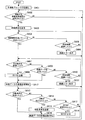
次に、映像送信装置100の動作について説明する。図7は、本実施形態における映像送信装置100の動作手順を示したフローチャートである。
(ステップS701)制御部101は、映像送信装置100の電源が投入された場合、映像送信装置100が備える各部を初期化する。その後、ステップS702の処理に進む。
Next, the operation of the
(Step S <b> 701) When the power of the
(ステップS702)映像送信装置100は、映像受信装置200から送信される接続要求メッセージを無線通信回路部104が受信するまで処理を待機する。そして、映像受信装置200から送信される接続要求メッセージを無線通信回路部104が受信した場合、ステップS703の処理に進む。具体的には、無線通信回路部104は、映像受信装置200から接続要求メッセージが送信された場合、この接続要求メッセージを受信する。制御部101は、映像受信装置200から送信される接続要求メッセージを無線通信回路部104が受信したか否かを判定する。そして、接続要求メッセージを受信したと制御部101が判定した場合にはステップS703の処理に進み、それ以外の場合にはステップS702の処理を再度実行する。なお、接続要求メッセージには、接続要求メッセージを送信した映像受信装置200のMACアドレスと、装置名と、EDID更新フラグとが含まれている。映像送信装置100の制御部101は、接続要求メッセージから、接続要求メッセージを送信した映像受信装置200のMACアドレスと、装置名と、EDID更新フラグとを取得する。
(Step S <b> 702) The
(ステップS703)制御部101は、無線通信回路部104を介して、接続要求応答メッセージを映像受信装置200に対して送信する。その後、ステップS704の処理に進む。
(ステップS704)制御部101は、ステップS702の処理で取得した、接続要求メッセージを送信した映像受信装置200のMACアドレスが、ROM102が記憶する接続装置リストに含まれているか否かを判定する。接続要求メッセージを送信した映像受信装置200のMACアドレスが接続装置リストに含まれていると制御部101が判定した場合にはステップS705の処理に進み、それ以外の場合にはステップS707の処理に進む。
(Step S <b> 703) The
(Step S <b> 704) The
(ステップS705)制御部101は、ステップS702の処理で取得したEDID更新フラグは「1」であるか否か(セットされているか否か)を判定する。EDID更新フラグは「1」であると制御部101が判定した場合にはステップS707の処理に進み、それ以外の場合にはステップS706の処理に進む。
ステップS706〜ステップS722の処理は、第1の実施形態におけるステップS306〜ステップS321の処理と同様の処理である。
(Step S705) The
The processing from step S706 to step S722 is the same processing as the processing from step S306 to step S321 in the first embodiment.
なお、特許請求の範囲に記載の通信ステップは、例えばステップS702,S703,S722の処理に相当する。また、特許請求の範囲に記載の画像変更ステップは、例えばステップS712,S721の処理に相当する。また、特許請求の範囲に記載の記憶ステップは、例えばステップS707〜S709,S718,S720の処理に相当する。また、特許請求の範囲に記載の制御ステップは、例えばステップS704〜S706,S713の処理に相当する。また、本発明において、例えば、図7のステップS702〜S709,S712,S713,S718,S720〜S722の処理は必須の構成要件である。 Note that the communication step recited in the claims corresponds to, for example, the processing of steps S702, S703, and S722. Further, the image changing step described in the claims corresponds to, for example, the processing of steps S712 and S721. The storage step described in the claims corresponds to, for example, the processes of steps S707 to S709, S718, and S720. Moreover, the control step described in the claims corresponds to, for example, the processes of steps S704 to S706 and S713. In the present invention, for example, the processing of steps S702 to S709, S712, S713, S718, and S720 to S722 in FIG.
次に、映像送信装置200の動作について説明する。図8は、本実施形態における映像受信装置200の動作手順を示したフローチャートである。
(ステップS801)制御部101は、映像受信装置200の電源が投入された場合、映像受信装置200が備える各部を初期化する。その後、ステップS802の処理に進む。
Next, the operation of the
(Step S <b> 801) When the power of the
(ステップS802)映像受信装置200のユーザーは、映像受信装置200と接続する映像送信装置100を選択する場合、操作部207を操作して接続する映像受信装置200の選択指示を入力する。制御部201は、操作部207が選択指示の入力を受け付けたか否かを判定する。選択指示の入力を受け付けたと制御部201が判定した場合にはステップS803の処理に進み、それ以外の場合にはステップS802の処理を再度実行する。
(Step S802) When the user of the
(ステップS803)制御部201は、ステップS802の処理で選択された映像送信装置100との無線接続が切断された後、映像受信装置200に接続されているモニター部210のEDIDが変更されたか否かを判定する。ステップS802の処理で選択された映像送信装置100との無線接続が切断された後、映像受信装置200に接続されているモニター部210のEDIDが変更されたと制御部201が判定した場合にはステップS804の処理に進み、それ以外の場合にはステップS805の処理に進む。また、ステップS802の処理で選択された映像送信装置100に初めて接続する場合もステップS805の処理に進む。
(Step S803) The
(ステップS804)制御部201は、ステップS802の処理で選択された映像送信装置100のMACアドレスと装置名と、EDID変更フラグ「1」とを関連付けて、ROM202が記憶するEDID変更リストに記憶させる。なお、既に、ROM202が記憶するEDID変更リストに、ステップS802の処理で選択された映像送信装置100のMACアドレスと装置名とが記憶されている場合、このMACアドレスに関連付けられているEDID更新フラグを「1」とする。その後、ステップS805の処理に進む。
(Step S804) The
ステップS805〜ステップS808の処理は、第1の実施形態におけるステップS403〜ステップS406の処理と同様の処理である。
(ステップS809)無線通信回路部204は、映像送信装置100からEDID要求メッセージが送信された場合、このEDID要求メッセージを受信する。制御部201は、映像送信装置100から送信されるEDID要求メッセージを無線通信回路部204が受信したか否かを判定する。EDID要求メッセージを受信したと制御部201が判定した場合にはステップS810の処理に進み、それ以外の場合にはステップS812の処理に進む。
The processes in steps S805 to S808 are the same as the processes in steps S403 to S406 in the first embodiment.
(Step S809) When the EDID request message is transmitted from the
(ステップS810)制御部201は、モニター部210が備えるEDID記憶部211から、モニター部210のEDIDを読み出す。そして、制御部201は、無線通信回路部204を介して、モニター部210のEDIDを映像送信装置100に対して送信する。その後、ステップS811の処理に進む。
(ステップS811)制御部201は、ROM202が記憶するEDID変更リストに記録されている、ステップS802の処理で選択された映像送信装置100のMACアドレスと装置名とに関連付けられているEDID更新フラグを「0」とする。その後、ステップS815の処理に進む。
ステップS812〜ステップS821の処理は、第1の実施形態におけるステップS403〜ステップS406の処理と同様の処理である。
(Step S <b> 810) The
(Step S811) The
The processing from step S812 to step S821 is the same processing as the processing from step S403 to step S406 in the first embodiment.
上述した通り、本実施形態によれば、映像送信装置100との無線接続が切断された後、映像受信装置200に接続されているモニター部210のEDIDが変更された場合、映像受信装置200の制御部201は、この映像送信装置100を一意に特定するMACアドレスと装置名と、EDID変更フラグ「1」とを関連付けてROM202が記憶するEDID変更リストに記憶させる。また、ROM202が記憶するEDID変更リストに、EDID変更フラグ「1」と関連付けて記憶されているMACアドレスで一意に特定される映像送信装置100と映像受信装置200とが再度無線接続を確立し、この映像送信装置100に対してEDIDを送信した場合、制御部201は、このEDID変更フラグを「0」に変更する。これにより、EDID変更フラグを参照することで、映像受信装置200と映像送信装置100とが通信接続を確立した後、接続を切断し、再度通信接続を確立するまでに、映像受信装置200に接続されているモニター部210のEDIDが変更されたか否かを判定することができる。
As described above, according to the present embodiment, when the EDID of the
また、映像送信装置100は、映像受信装置200からEDID変更フラグを受信し、EDID更新フラグが「1」、すなわち、通信接続を確立した後、接続を切断し、再度通信接続を確立するまでに、映像受信装置200に接続されているモニター部210のEDIDが変更されたか否かを判定する。そして、通信接続を確立した後、接続を切断し、再度通信接続を確立するまでに、映像受信装置200に接続されているモニター部210のEDIDが変更されたと判定した場合、映像送信装置100は、映像受信装置200から再度EDIDを取得する。これにより、通信接続を確立した後、接続を切断し、再度通信接続を確立するまでに、映像受信装置200に接続されているモニター部210のEDIDが変更された場合においても、映像送信装置100は、映像受信装置200に接続されているモニター部210が再生することが可能な形式の映像データを送信することができる。
Also, the
以上、この発明の第1の実施形態および第2の実施形態について図面を参照して詳述してきたが、具体的な構成はこの実施形態に限られるものではなく、この発明の要旨を逸脱しない範囲の設計等も含まれる。 Although the first embodiment and the second embodiment of the present invention have been described in detail with reference to the drawings, the specific configuration is not limited to this embodiment and does not depart from the gist of the present invention. Range design etc. are also included.
例えば、上述した実施形態では、映像受信装置200が映像送信装置100に対して接続要求メッセージを送信し、映像送信装置100が接続要求メッセージに対する接続要求応答メッセージを映像受信装置200に対して送信することで、映像送信装置100と映像受信装置200とは無線通信接続を確立しているが、これに限らない。例えば、映像送信装置100が映像受信装置200に対して接続要求メッセージを送信し、映像受信装置200が接続要求メッセージに対する接続要求応答メッセージを映像送信装置100に対して送信することで、映像送信装置100と映像受信装置200とが無線通信接続を確立するようにしてもよい。
For example, in the above-described embodiment, the
なお、上述した映像送信装置100が備える各部の機能全体あるいはその一部、映像受信装置200が備える各部の機能全体あるいはその一部は、これらの機能を実現するためのプログラムをコンピュータ読み取り可能な記録媒体に記録して、この記録媒体に記録されたプログラムをコンピュータシステムに読み込ませ、実行することによって実現しても良い。なお、ここでいう「コンピュータシステム」とは、OSや周辺機器等のハードウェアを含むものとする。
Note that all or some of the functions of each unit included in the
また、「コンピュータ読み取り可能な記録媒体」とは、フレキシブルディスク、光磁気ディスク、ROM、CD−ROM等の可搬媒体、コンピュータシステムに内蔵されるハードディスク等の記憶部のことをいう。さらに「コンピュータ読み取り可能な記録媒体」とは、インターネット等のネットワークや電話回線等の通信回線を介してプログラムを送信する場合の通信線のように、短時刻の間、動的にプログラムを保持するもの、その場合のサーバやクライアントとなるコンピュータシステム内部の揮発性メモリのように、一定時刻プログラムを保持しているものも含んでも良い。また上記プログラムは、前述した機能の一部を実現するためのものであっても良く、さらに前述した機能をコンピュータシステムにすでに記録されているプログラムとの組み合わせで実現できるものであっても良い。 The “computer-readable recording medium” refers to a portable medium such as a flexible disk, a magneto-optical disk, a ROM, and a CD-ROM, and a storage unit such as a hard disk built in the computer system. Further, the “computer-readable recording medium” dynamically holds a program for a short time, like a communication line when transmitting a program via a network such as the Internet or a communication line such as a telephone line. It is also possible to include those that hold a program for a certain time, such as a volatile memory inside a computer system serving as a server or client in that case. The program may be a program for realizing a part of the functions described above, and may be a program capable of realizing the functions described above in combination with a program already recorded in a computer system.
100・・・映像送信装置、101,201・・・制御部、102,202・・・ROM、103,203・・・RAM、104,204・・・無線通信回路部、105,205・・・アンテナ、106,206・・・映像信号処理部、107,207・・・操作部、200・・・映像受信装置、110・・・映像データ供給装置、210・・・モニター部、211・・・EDID記憶部
DESCRIPTION OF
Claims (7)
前記無線通信接続を確立した前記表示装置が有する前記表示部の設定情報に基づいて、当該表示装置に無線送信する前記画像のフォーマットを変更する画像変更部と、
前記表示装置を一意に識別する表示装置識別子と、当該表示装置が有する前記表示部の設定情報とを対応付けて記憶する記憶部と、
前記表示装置と前記無線通信接続を確立するときに前記記憶部が当該表示装置を一意に識別する前記表示装置識別子と前記設定情報とを対応付けて記憶している場合、当該表示装置に対して前記設定情報の送信要求を行わず、前記記憶部が記憶している前記設定情報に基づいて前記画像変更部に前記画像のフォーマットを変更させ、フォーマットが変更された当該画像を前記通信部に無線送信させる制御部と、
を有することを特徴とする画像送信装置。 Between establishing a wireless communication connection with a display device having a display unit that displays an image in time series and ending the wireless communication connection, the image is displayed on the display device in time series. A communication unit for wireless transmission;
An image changing unit that changes a format of the image to be wirelessly transmitted to the display device based on setting information of the display unit included in the display device that has established the wireless communication connection;
A storage unit that associates and stores a display device identifier that uniquely identifies the display device and setting information of the display unit included in the display device;
When the storage unit stores the display device identifier uniquely identifying the display device and the setting information in association with the display device when establishing the wireless communication connection with the display device, Without making a transmission request for the setting information, the image changing unit is caused to change the format of the image based on the setting information stored in the storage unit, and the image whose format has been changed is wirelessly transmitted to the communication unit. A control unit to transmit,
An image transmitting apparatus comprising:
ことを特徴とする請求項1に記載の画像送信装置。 When the storage unit does not store the display device identifier that uniquely identifies the display device and the setting information in association with each other, the control unit requests the display device to transmit the setting information. The image transmitting apparatus according to claim 1.
ことを特徴とする請求項2に記載の画像送信装置。 When the control unit does not store the display device identifier and the setting information in association with each other when the storage unit uniquely identifies the display device when establishing the wireless communication connection with the display device, The image transmission apparatus according to claim 2, wherein a transmission request for the setting information is made to a display apparatus.
ことを特徴とする請求項1または請求項2に記載の画像送信装置。 The control unit, when the communication unit receives change notification information indicating that the setting information has been changed from the display device, makes a transmission request for the setting information to the display device. The image transmission apparatus according to claim 1 or 2.
ことを特徴とする請求項4に記載の画像送信装置。 The image transmission device according to claim 4, wherein the change notification information is included in a connection request message transmitted from the display device.
画像変更部が、前記無線通信接続を確立した前記表示装置が有する前記表示部の設定情報に基づいて、当該表示装置に無線送信する前記画像のフォーマットを変更する画像変更ステップと、
記憶部が、前記表示装置を一意に識別する表示装置識別子と、当該表示装置が有する前記表示部の設定情報とを対応付けて記憶する記憶ステップと、
制御部が、前記表示装置と前記無線通信接続を確立するときに前記記憶部が当該表示装置を一意に識別する前記表示装置識別子と前記設定情報とを対応付けて記憶している場合、当該表示装置に対して前記設定情報の送信要求を行わず、前記記憶部が記憶している前記設定情報に基づいて前記画像変更部に前記画像のフォーマットを変更させ、フォーマットが変更された当該画像を前記通信部に無線送信させる制御ステップと、
を含むことを特徴とする画像送信方法。 The communication unit displays the image on the display device between the time when the wireless communication connection is disconnected after the wireless communication connection is established with the display device having the display unit that displays the images in time series. A communication step of wireless transmission in time series;
An image changing step for changing a format of the image to be wirelessly transmitted to the display device based on setting information of the display unit included in the display device that has established the wireless communication connection;
A storage step in which the storage unit stores the display device identifier for uniquely identifying the display device in association with the setting information of the display unit included in the display device;
When the control unit stores the display device identifier and the setting information in association with each other when the storage unit uniquely establishes the display device when establishing the wireless communication connection with the display device, the display Without making a transmission request for the setting information to the apparatus, the image changing unit is caused to change the format of the image based on the setting information stored in the storage unit, and the image whose format has been changed is A control step for causing the communication unit to wirelessly transmit;
An image transmission method comprising:
画像を時系列的に表示する表示部を有する表示装置と無線通信接続を確立してから当該無線通信接続が切断される時点までの間に、当該表示装置に対して前記画像を時系列的に無線送信する通信手段と、
前記無線通信接続を確立した前記表示装置が有する前記表示部の設定情報に基づいて、当該表示装置に無線送信する前記画像のフォーマットを変更する画像変更手段と、
前記表示装置を一意に識別する表示装置識別子と、当該表示装置が有する前記表示部の設定情報とを対応付けて記憶する記憶手段と、
前記表示装置と前記無線通信接続を確立するときに前記記憶手段が当該表示装置を一意に識別する前記表示装置識別子と前記設定情報とを対応付けて記憶している場合、当該表示装置に対して前記設定情報の送信要求を行わず、前記記憶手段が記憶している前記設定情報に基づいて前記画像変更手段に前記画像のフォーマットを変更させ、フォーマットが変更された当該画像を前記通信手段に無線送信させる制御手段と、
して機能させるためのプログラム。 Computer
Between establishing a wireless communication connection with a display device having a display unit that displays an image in time series and ending the wireless communication connection, the image is displayed on the display device in time series. A communication means for wireless transmission;
Image changing means for changing the format of the image to be wirelessly transmitted to the display device based on the setting information of the display unit of the display device that has established the wireless communication connection;
Storage means for storing the display device identifier for uniquely identifying the display device and the setting information of the display unit included in the display device in association with each other;
When the storage unit stores the display device identifier uniquely identifying the display device and the setting information in association with the display device when establishing the wireless communication connection with the display device. Without making a transmission request for the setting information, the image changing unit changes the format of the image based on the setting information stored in the storage unit, and the image whose format has been changed is wirelessly transmitted to the communication unit. Control means for transmitting;
Program to make it function.
Priority Applications (5)
| Application Number | Priority Date | Filing Date | Title |
|---|---|---|---|
| JP2011244352A JP2013102325A (en) | 2011-11-08 | 2011-11-08 | Image transmission device, image transmission method, and program |
| PCT/JP2012/079002 WO2013069738A1 (en) | 2011-11-08 | 2012-11-08 | Image transmission device, image transmission method and program |
| CN201280052808.3A CN104025613B (en) | 2011-11-08 | 2012-11-08 | Picture transmitter device, image sending method and program |
| EP12847058.0A EP2779639A4 (en) | 2011-11-08 | 2012-11-08 | Image transmission device, image transmission method and program |
| US14/266,400 US8988613B2 (en) | 2011-11-08 | 2014-04-30 | Image transmission device, image transmission method, and computer-readable device |
Applications Claiming Priority (1)
| Application Number | Priority Date | Filing Date | Title |
|---|---|---|---|
| JP2011244352A JP2013102325A (en) | 2011-11-08 | 2011-11-08 | Image transmission device, image transmission method, and program |
Publications (2)
| Publication Number | Publication Date |
|---|---|
| JP2013102325A true JP2013102325A (en) | 2013-05-23 |
| JP2013102325A5 JP2013102325A5 (en) | 2014-11-27 |
Family
ID=48290108
Family Applications (1)
| Application Number | Title | Priority Date | Filing Date |
|---|---|---|---|
| JP2011244352A Pending JP2013102325A (en) | 2011-11-08 | 2011-11-08 | Image transmission device, image transmission method, and program |
Country Status (5)
| Country | Link |
|---|---|
| US (1) | US8988613B2 (en) |
| EP (1) | EP2779639A4 (en) |
| JP (1) | JP2013102325A (en) |
| CN (1) | CN104025613B (en) |
| WO (1) | WO2013069738A1 (en) |
Cited By (1)
| Publication number | Priority date | Publication date | Assignee | Title |
|---|---|---|---|---|
| JP2017515331A (en) * | 2014-03-12 | 2017-06-08 | エルジー エレクトロニクス インコーポレイティド | Data transmission / reception device and method using HDMI (registered trademark) |
Families Citing this family (2)
| Publication number | Priority date | Publication date | Assignee | Title |
|---|---|---|---|---|
| JP2014082545A (en) * | 2012-10-12 | 2014-05-08 | Funai Electric Co Ltd | Recording and reproducing apparatus and control method of the same |
| CN107896314B (en) * | 2017-11-10 | 2019-12-24 | 浙江大华技术股份有限公司 | Video transmission method and device |
Citations (6)
| Publication number | Priority date | Publication date | Assignee | Title |
|---|---|---|---|---|
| JP2007108198A (en) * | 2005-10-11 | 2007-04-26 | Sony Corp | Information processor and method, and program |
| JP2009049787A (en) * | 2007-08-21 | 2009-03-05 | Funai Electric Co Ltd | Electronic equipment |
| JP2009182912A (en) * | 2008-02-01 | 2009-08-13 | Hitachi Ltd | Video/audio reproducing apparatus |
| JP2010098378A (en) * | 2008-10-14 | 2010-04-30 | Sharp Corp | Radio transmission system |
| JP2011015245A (en) * | 2009-07-03 | 2011-01-20 | Hitachi Consumer Electronics Co Ltd | Video transmitter apparatus and video receiver apparatus |
| WO2011040007A1 (en) * | 2009-10-01 | 2011-04-07 | パナソニック株式会社 | Wireless communication system, video apparatus adapter apparatus, video apparatus, and wireless communication system control method |
Family Cites Families (8)
| Publication number | Priority date | Publication date | Assignee | Title |
|---|---|---|---|---|
| US7499030B2 (en) * | 2001-11-30 | 2009-03-03 | Texas Instruments Incorporated | Graphics initialization for wireless display devices |
| CN101385278B (en) * | 2006-02-14 | 2011-06-22 | 松下电器产业株式会社 | Wireless communication system |
| JP4879830B2 (en) | 2006-02-14 | 2012-02-22 | パナソニック株式会社 | Wireless communication system |
| CN201115245Y (en) * | 2007-09-04 | 2008-09-10 | 享乐科技股份有限公司 | Heat radiation pad with temperature sensing |
| US8675682B2 (en) * | 2008-03-27 | 2014-03-18 | Panasonic Corporation | Wireless communication device for processing packet including at least one of video output format of video data and audio output format of audio data |
| JP2009284047A (en) * | 2008-05-20 | 2009-12-03 | Panasonic Corp | Adaptor device for source apparatus, and method of controlling adaptor device for source apparatus |
| JP5351960B2 (en) * | 2009-05-14 | 2013-11-27 | パナソニック株式会社 | Video data transmission method |
| WO2011064947A1 (en) * | 2009-11-24 | 2011-06-03 | パナソニック株式会社 | Adaptor device for source device and method for controlling adaptor device for source device |
-
2011
- 2011-11-08 JP JP2011244352A patent/JP2013102325A/en active Pending
-
2012
- 2012-11-08 WO PCT/JP2012/079002 patent/WO2013069738A1/en active Application Filing
- 2012-11-08 EP EP12847058.0A patent/EP2779639A4/en not_active Withdrawn
- 2012-11-08 CN CN201280052808.3A patent/CN104025613B/en not_active Expired - Fee Related
-
2014
- 2014-04-30 US US14/266,400 patent/US8988613B2/en active Active
Patent Citations (6)
| Publication number | Priority date | Publication date | Assignee | Title |
|---|---|---|---|---|
| JP2007108198A (en) * | 2005-10-11 | 2007-04-26 | Sony Corp | Information processor and method, and program |
| JP2009049787A (en) * | 2007-08-21 | 2009-03-05 | Funai Electric Co Ltd | Electronic equipment |
| JP2009182912A (en) * | 2008-02-01 | 2009-08-13 | Hitachi Ltd | Video/audio reproducing apparatus |
| JP2010098378A (en) * | 2008-10-14 | 2010-04-30 | Sharp Corp | Radio transmission system |
| JP2011015245A (en) * | 2009-07-03 | 2011-01-20 | Hitachi Consumer Electronics Co Ltd | Video transmitter apparatus and video receiver apparatus |
| WO2011040007A1 (en) * | 2009-10-01 | 2011-04-07 | パナソニック株式会社 | Wireless communication system, video apparatus adapter apparatus, video apparatus, and wireless communication system control method |
Cited By (1)
| Publication number | Priority date | Publication date | Assignee | Title |
|---|---|---|---|---|
| JP2017515331A (en) * | 2014-03-12 | 2017-06-08 | エルジー エレクトロニクス インコーポレイティド | Data transmission / reception device and method using HDMI (registered trademark) |
Also Published As
| Publication number | Publication date |
|---|---|
| EP2779639A1 (en) | 2014-09-17 |
| US20140232936A1 (en) | 2014-08-21 |
| EP2779639A4 (en) | 2015-01-21 |
| CN104025613A (en) | 2014-09-03 |
| WO2013069738A1 (en) | 2013-05-16 |
| CN104025613B (en) | 2017-06-06 |
| US8988613B2 (en) | 2015-03-24 |
Similar Documents
| Publication | Publication Date | Title |
|---|---|---|
| US20170048577A1 (en) | Remote control method related to hdmi-cec specification and system thereof | |
| US8713208B2 (en) | Image display device and method of changing first EDID with second EDID wherein the second EDID information is compatible with image display device | |
| JP6423172B2 (en) | Wireless endoscope system, display device, and program | |
| US10237508B2 (en) | Method and device for displaying boot screen | |
| JP6987556B2 (en) | Communication equipment, information processing methods and programs | |
| JP2013102325A (en) | Image transmission device, image transmission method, and program | |
| JP5690206B2 (en) | Wireless terminal and wireless system | |
| JP2015050631A (en) | Display system, information terminal, selection control program, and selection control method | |
| JP6970578B2 (en) | Communication equipment and its control method, program | |
| KR20150028501A (en) | Remote controller and method for controlling the same | |
| JP2015055827A (en) | Display system, display device, display control program and display control method | |
| KR101493750B1 (en) | Display apparatus operated by multiple modes and mode changing method thereof | |
| JP2016174221A (en) | Communication device, communication system, and communication method | |
| JP6222714B2 (en) | Display screen changing method and display device | |
| JP2023058766A (en) | Sink apparatus and information processing method | |
| JP2012004964A (en) | Display device | |
| JP6553788B2 (en) | Display device | |
| JP6396560B2 (en) | Display device | |
| JP2017192000A (en) | Communication device, control method and program | |
| JP2016174220A (en) | Communication device, communication system, and communication method | |
| JP5926669B2 (en) | Video display device | |
| JP2020068498A (en) | Display system, display unit, and method for controlling display system | |
| JP2013038820A (en) | Video display apparatus and control method thereof, and video output apparatus and control method thereof | |
| JP2019193300A (en) | Display device | |
| JP2019174719A (en) | Multi-display device |
Legal Events
| Date | Code | Title | Description |
|---|---|---|---|
| A521 | Request for written amendment filed |
Free format text: JAPANESE INTERMEDIATE CODE: A523 Effective date: 20141009 |
|
| A621 | Written request for application examination |
Free format text: JAPANESE INTERMEDIATE CODE: A621 Effective date: 20141009 |
|
| A521 | Request for written amendment filed |
Free format text: JAPANESE INTERMEDIATE CODE: A821 Effective date: 20141010 |
|
| A131 | Notification of reasons for refusal |
Free format text: JAPANESE INTERMEDIATE CODE: A131 Effective date: 20151201 |
|
| A521 | Request for written amendment filed |
Free format text: JAPANESE INTERMEDIATE CODE: A821 Effective date: 20160129 |
|
| A02 | Decision of refusal |
Free format text: JAPANESE INTERMEDIATE CODE: A02 Effective date: 20160223 |