JP2013041804A - Backlight unit and illumination system including the same - Google Patents
Backlight unit and illumination system including the same Download PDFInfo
- Publication number
- JP2013041804A JP2013041804A JP2012014221A JP2012014221A JP2013041804A JP 2013041804 A JP2013041804 A JP 2013041804A JP 2012014221 A JP2012014221 A JP 2012014221A JP 2012014221 A JP2012014221 A JP 2012014221A JP 2013041804 A JP2013041804 A JP 2013041804A
- Authority
- JP
- Japan
- Prior art keywords
- backlight unit
- inclined surface
- reflector
- unit according
- distance value
- Prior art date
- Legal status (The legal status is an assumption and is not a legal conclusion. Google has not performed a legal analysis and makes no representation as to the accuracy of the status listed.)
- Pending
Links
Images


Classifications
-
- G—PHYSICS
- G02—OPTICS
- G02F—OPTICAL DEVICES OR ARRANGEMENTS FOR THE CONTROL OF LIGHT BY MODIFICATION OF THE OPTICAL PROPERTIES OF THE MEDIA OF THE ELEMENTS INVOLVED THEREIN; NON-LINEAR OPTICS; FREQUENCY-CHANGING OF LIGHT; OPTICAL LOGIC ELEMENTS; OPTICAL ANALOGUE/DIGITAL CONVERTERS
- G02F1/00—Devices or arrangements for the control of the intensity, colour, phase, polarisation or direction of light arriving from an independent light source, e.g. switching, gating or modulating; Non-linear optics
- G02F1/01—Devices or arrangements for the control of the intensity, colour, phase, polarisation or direction of light arriving from an independent light source, e.g. switching, gating or modulating; Non-linear optics for the control of the intensity, phase, polarisation or colour
- G02F1/13—Devices or arrangements for the control of the intensity, colour, phase, polarisation or direction of light arriving from an independent light source, e.g. switching, gating or modulating; Non-linear optics for the control of the intensity, phase, polarisation or colour based on liquid crystals, e.g. single liquid crystal display cells
- G02F1/133—Constructional arrangements; Operation of liquid crystal cells; Circuit arrangements
- G02F1/1333—Constructional arrangements; Manufacturing methods
- G02F1/1335—Structural association of cells with optical devices, e.g. polarisers or reflectors
- G02F1/1336—Illuminating devices
- G02F1/133615—Edge-illuminating devices, i.e. illuminating from the side
-
- G—PHYSICS
- G02—OPTICS
- G02F—OPTICAL DEVICES OR ARRANGEMENTS FOR THE CONTROL OF LIGHT BY MODIFICATION OF THE OPTICAL PROPERTIES OF THE MEDIA OF THE ELEMENTS INVOLVED THEREIN; NON-LINEAR OPTICS; FREQUENCY-CHANGING OF LIGHT; OPTICAL LOGIC ELEMENTS; OPTICAL ANALOGUE/DIGITAL CONVERTERS
- G02F1/00—Devices or arrangements for the control of the intensity, colour, phase, polarisation or direction of light arriving from an independent light source, e.g. switching, gating or modulating; Non-linear optics
- G02F1/01—Devices or arrangements for the control of the intensity, colour, phase, polarisation or direction of light arriving from an independent light source, e.g. switching, gating or modulating; Non-linear optics for the control of the intensity, phase, polarisation or colour
- G02F1/13—Devices or arrangements for the control of the intensity, colour, phase, polarisation or direction of light arriving from an independent light source, e.g. switching, gating or modulating; Non-linear optics for the control of the intensity, phase, polarisation or colour based on liquid crystals, e.g. single liquid crystal display cells
- G02F1/133—Constructional arrangements; Operation of liquid crystal cells; Circuit arrangements
- G02F1/1333—Constructional arrangements; Manufacturing methods
- G02F1/133308—Support structures for LCD panels, e.g. frames or bezels
- G02F1/133314—Back frames
-
- G—PHYSICS
- G02—OPTICS
- G02F—OPTICAL DEVICES OR ARRANGEMENTS FOR THE CONTROL OF LIGHT BY MODIFICATION OF THE OPTICAL PROPERTIES OF THE MEDIA OF THE ELEMENTS INVOLVED THEREIN; NON-LINEAR OPTICS; FREQUENCY-CHANGING OF LIGHT; OPTICAL LOGIC ELEMENTS; OPTICAL ANALOGUE/DIGITAL CONVERTERS
- G02F2201/00—Constructional arrangements not provided for in groups G02F1/00 - G02F7/00
- G02F2201/34—Constructional arrangements not provided for in groups G02F1/00 - G02F7/00 reflector
Abstract
Description
本発明の実施例は、バックライトユニット及びこれを含む照明システムに関する。 Embodiments described herein relate generally to a backlight unit and a lighting system including the backlight unit.
一般に、大型ディスプレイ装置の代表には、LCD(Liquid Crystal Display)またはPDP(Plasma Display Panel)などがある。 In general, representatives of large display devices include LCD (Liquid Crystal Display) and PDP (Plasma Display Panel).
自発光型のPDPとは違い、LCDは、自体発光する発光素子を備えておらず、別のバックライトユニットが必須である。 Unlike the self-light emitting PDP, the LCD does not include a light emitting element that emits light, and a separate backlight unit is essential.
LCDに用いられるバックライトユニットは、光源の位置によって、エッジ(edge)方式のバックライトユニットと直下方式のバックライトユニットとに大別される。エッジ方式は、LCDパネルの左右側面または上下側面に光源を配置し、導光板を用いて光を前面に均一に分散させるため、光の均一性がよく、パネルの超薄型化が可能である。 Backlight units used in LCDs are roughly classified into edge type backlight units and direct type backlight units depending on the position of the light source. In the edge method, light sources are arranged on the left and right side surfaces or upper and lower side surfaces of the LCD panel, and light is evenly distributed on the front surface using a light guide plate, so that the light uniformity is good and the panel can be made very thin. .
直下方式は、通常、20インチ以上のディスプレイに用いられる技術で、パネルの下部に光源を複数個配置するから、エッジ方式に比べて優れた光効率を有し、よって、高輝度を要求する大型ディスプレイに主に用いられる。 The direct method is a technology usually used for displays of 20 inches or more, and since a plurality of light sources are arranged at the lower part of the panel, it has a light efficiency superior to that of the edge method, and thus requires a large luminance. Mainly used for displays.
既存エッジ方式や直下方式のバックライトユニットの光源には、CCFL(Cold Cathode Fluorescent Lamp)を用いてきた。 CCFL (Cold Cathode Fluorescent Lamp) has been used for the light source of the backlight unit of the existing edge method or the direct type.
しかし、CCFLを用いたバックライトユニットは、CCFLに常に電源が印加されるから相当量の電力を消耗する、CRTに比べて約70%レベルの色再現率を示す、水銀の添加により環境汚染を招くといった欠点がある。 However, the backlight unit using CCFL consumes a considerable amount of power because power is always applied to CCFL, and shows about 70% level color reproduction rate compared to CRT. There is a disadvantage of inviting.
これを解消するための代替品として、現在、LED(Light Emitting diode)を用いたバックライトユニットに関する研究が活発に行われている。 As an alternative for solving this problem, research on a backlight unit using an LED (Light Emitting Diode) is being actively conducted.
LEDをバックライトユニットに用いる場合、LEDアレイの部分的なオン/オフが可能なため、消耗電力を画期的に低減できる。なお、RGB LEDの場合、NTSC(National Television System Committee)色再現範囲仕様の100%を上回り、より鮮明な画質を消費者に提供することができる。 When the LED is used in the backlight unit, the power consumption can be dramatically reduced because the LED array can be partially turned on / off. In the case of an RGB LED, it exceeds 100% of the NTSC (National Television System Committee) color reproduction range specification, and a clearer image quality can be provided to consumers.
また、半導体工程で製作されるLEDは、環境に無害であるといった特長を有する。 In addition, LEDs manufactured in a semiconductor process have a feature that they are harmless to the environment.
現在、前述の利点を有するLEDを採用したLCD製品が続々と発売されているが、既存CCFL光源と駆動メカニズムが異なるし、使用されている駆動ドライバ及びPCB基板などが高価であるという欠点がある。そのため、LEDを採用したバックライトユニットは未だ高価のLCD製品にのみ適用されている。 Currently, LCD products using LEDs having the above-mentioned advantages are being put on the market one after another. However, the drive mechanism is different from the existing CCFL light source, and the drive drivers and PCB boards used are expensive. . For this reason, backlight units employing LEDs are still applied only to expensive LCD products.
LEDアレイが放出される光を表示装置の前方に導く導光板を別途に用いずにエアー(air)で光を導くLEDバックライトユニットでは、LEDアレイから出た光が反射されて表示装置の前方に導かれるようにするボトムカバー(bottom cover)の構造が重要である。 In an LED backlight unit that guides light by air without using a separate light guide plate that guides light emitted from the LED array to the front of the display device, the light emitted from the LED array is reflected to the front of the display device. The structure of the bottom cover is important.
本発明の実施例は、剛性を持つボトムカバーに、それぞれ異なる曲率半径の傾斜面を有するリフレクタ支持部を結合して、高強度且つ優れた反射特性を有するエアーガイド(air guide)を備えるバックライトユニット及びこれを含む照明システムを提供する。 According to an embodiment of the present invention, a backlight having an air guide having high strength and excellent reflection characteristics by coupling a reflector support portion having inclined surfaces with different curvature radii to a rigid bottom cover. A unit and a lighting system including the unit are provided.
本発明の実施例のバックライトユニットは、第1リフレクタ及びボトムカバーと、それぞれが、前記ボトムカバー上に配置され、少なくとも1つの変曲点を中心に隣接する少なくとも2個の第1及び第2傾斜面を有する複数のリフレクタ支持部と、前記複数のリフレクタ支持部に配置される第2リフレクタと、前記第1リフレクタと前記第2リフレクタとの間に配置される光源モジュールとを備える。また、上記バックライトユニットは、前記光源モジュール及び前記第1リフレクタが配置され、前記ボトムカバーの両側部に結合するカバープレートをさらに備えることができる。 The backlight unit according to the embodiment of the present invention includes a first reflector and a bottom cover, each of which is disposed on the bottom cover, and at least two first and second adjacent to each other centering on at least one inflection point. A plurality of reflector support portions having inclined surfaces, a second reflector disposed on the plurality of reflector support portions, and a light source module disposed between the first reflector and the second reflector. The backlight unit may further include a cover plate on which the light source module and the first reflector are disposed and coupled to both sides of the bottom cover.
前記リフレクタ支持部の中心領域は、平らな平面、膨らんだ曲面、または凹んだ曲面のいずれか1つの形状を有する。前記リフレクタ支持部は、前記ボトムカバーの中心を基準に対称な形状を有する。前記リフレクタ支持部の両端部は、前記カバープレートに固定できる。 The central region of the reflector support portion has any one shape of a flat plane, a swollen curved surface, or a concave curved surface. The reflector support part has a symmetrical shape with respect to the center of the bottom cover. Both ends of the reflector support part can be fixed to the cover plate.
また、上記バックライトユニットは、前記リフレクタ支持部と相対し、前記カバープレートにより支持される光学部材と、前記リフレクタ支持部の上部に形成されて前記光学部材を支持する少なくとも1つの支持ピンとをさらに備えることができる。 The backlight unit further includes an optical member that is opposed to the reflector support portion and is supported by the cover plate, and at least one support pin that is formed on the reflector support portion and supports the optical member. Can be provided.
また、前記リフレクタ支持部の背面と前記ボトムカバーの底面に少なくとも1つの締結部が形成され、前記リフレクタ支持部は前記ボトムカバーに前記締結部により固定されるとよい。 Further, it is preferable that at least one fastening portion is formed on a back surface of the reflector support portion and a bottom surface of the bottom cover, and the reflector support portion is fixed to the bottom cover by the fastening portion.
前記締結部は、前記リフレクタ支持部の背面に形成された少なくとも1つの嵌め突起と、前記嵌め突起が嵌挿され、前記ボトムカバーの底面に形成された少なくとも1つの嵌め溝とを備えることができる。ここで、前記嵌め突起は複数個であり、互いに異なる方向に延突した前記複数の嵌め突起が配置されるとよい。 The fastening portion may include at least one fitting protrusion formed on a back surface of the reflector support portion, and at least one fitting groove formed on the bottom surface of the bottom cover by inserting the fitting protrusion. . Here, there are a plurality of fitting protrusions, and the plurality of fitting protrusions extending in different directions may be arranged.
前記第1傾斜面は、前記第2傾斜面に比べてより前記光源モジュールに近接して配置され、前記第1及び第2傾斜面の曲率半径は互いに異なってもよい。 The first inclined surface may be disposed closer to the light source module than the second inclined surface, and the curvature radii of the first and second inclined surfaces may be different from each other.
前記第1傾斜面の最高高さと前記第2傾斜面の最高高さは互いに同一であっても、異なってもよい。例えば、前記第1傾斜面の最高高さは、前記第2傾斜面の最高高さよりも大きくてよい。前記第1傾斜面の曲率半径は、前記第2傾斜面の曲率半径より小さいまたは同一である。例えば、前記第1傾斜面の曲率半径と前記第2傾斜面の曲率半径との比は、1:1〜10でよい。 The maximum height of the first inclined surface and the maximum height of the second inclined surface may be the same as or different from each other. For example, the maximum height of the first inclined surface may be greater than the maximum height of the second inclined surface. The curvature radius of the first inclined surface is smaller than or the same as the curvature radius of the second inclined surface. For example, the ratio between the radius of curvature of the first inclined surface and the radius of curvature of the second inclined surface may be 1: 1-10.
前記変曲点を通る第1水平線と前記第1傾斜面の先端の一点を通る第2水平線との間の第1距離値は、前記第1水平線と前記第2傾斜面の先端の一点を通る第3水平線との間の第2距離値よりも小さい、大きい、または同一である。例えば、前記第1距離値と前記第2距離値との比は、1:1.1〜5であってもよく、1:0.01〜1であってもよい。 A first distance value between a first horizontal line passing through the inflection point and a second horizontal line passing through a point on the tip of the first inclined surface passes through the point on the tip of the first horizontal line and the second inclined surface. It is smaller, larger or the same as the second distance value between the third horizontal line. For example, the ratio between the first distance value and the second distance value may be 1: 1.1-5, or 1: 0.01-1.
前記変曲点を通る第1垂直線と前記第1傾斜面の先端の一点を通る第2垂直線との間の第3距離値は、前記第1垂直線と前記第2傾斜面の先端の一点を通る第3垂直線との間の第4距離値より小さいまたは同一でよい。例えば、前記第3距離値と前記第4距離値との比は、1:1〜20でよい。 The third distance value between the first vertical line passing through the inflection point and the second vertical line passing through one point of the tip of the first inclined surface is the distance between the first vertical line and the tip of the second inclined surface. It may be less than or equal to the fourth distance value between the third vertical line passing through a point. For example, the ratio between the third distance value and the fourth distance value may be 1: 1-20.
前記変曲点を通る第1水平線と前記光源モジュールの一点を通る第4水平線との間の第5距離値は、前記第1水平線と前記第2傾斜面の先端の一点を通る第3水平線との間の第2距離値より大きくてもよい。 The fifth distance value between the first horizontal line that passes through the inflection point and the fourth horizontal line that passes through one point of the light source module is the third horizontal line that passes through the first horizontal line and one point of the tip of the second inclined surface. It may be larger than the second distance value between.
他の実施例によれば、照明システムは、第1リフレクタ及びボトムカバーと、それぞれが、前記ボトムカバー上に配置され、少なくとも一つの変曲点を中心に隣接する少なくとも2個の第1及び第2傾斜面を有する複数のリフレクタ支持部と、前記複数のリフレクタ支持部に配置される第2リフレクタと、前記第1リフレクタと前記第2リフレクタとの間に配置される光源モジュールとを備えるバックライトユニットを含むことができる。 According to another embodiment, a lighting system includes a first reflector and a bottom cover, each of which is disposed on the bottom cover and is adjacent to at least one inflection point and is adjacent to the first reflector and the bottom cover. A backlight comprising a plurality of reflector support portions having two inclined surfaces, a second reflector disposed on the plurality of reflector support portions, and a light source module disposed between the first reflector and the second reflector. Units can be included.
本発明の実施例によれば、リフレクタ支持部をボトムカバーに結合させることによって、高強度で反射特性に優れたエアーガイドを有するバックライトユニットを提供でき、バックライトユニットの信頼性を向上させるこさができる。 According to the embodiment of the present invention, it is possible to provide a backlight unit having an air guide having high strength and excellent reflection characteristics by coupling the reflector support portion to the bottom cover, and improving the reliability of the backlight unit. Can do.
下記の図面を参照して実施例について詳細に説明する。ただし、図面中、同一の構成要素には同一の参照符号を付する。
以下、本発明の実施例を、添付の図面を参照して説明する。 Hereinafter, embodiments of the present invention will be described with reference to the accompanying drawings.
本実施例の説明において、ある構成要素(element)の「上(上部)」または「下(下部)」(on or under)に他の構成要素が形成されるという記載は、これらの両構成要素が相互直接(directly)接触して形成される場合も、これら両構成要素の間に1つ以上のさらに他の構成要素が介在して(indirectly)形成される場合も含むことができる。また「上(上部)」または「下(下部)」(on or under)と表現される場合、1つの構成要素を基準に上方を指す場合もあり、下方を指す場合もある。 In the description of the present embodiment, the description that another component is formed on the “upper (upper)” or “lower (lower)” (on or under) of an element is both of these components. May be formed in direct contact with each other, or may be formed with one or more other components interposed between these two components. In addition, when expressed as “upper (upper)” or “lower (lower)” (on or under), there is a case where the upper part is indicated with reference to one component, and there is a case where the lower part is indicated.
図面において、各構成要素の厚さや大きさは、説明の便宜及び明確性のために、誇張、省略または概略して示したもので、実際の大きさを全的に反映するものではない。 In the drawings, the thickness and size of each component are exaggerated, omitted, or schematically shown for convenience of description and clarity, and do not fully reflect the actual size.
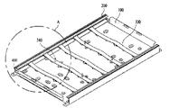
図1は、本実施例に係る2エッジタイプのバックライトユニットの斜視図である。 FIG. 1 is a perspective view of a two-edge type backlight unit according to the present embodiment.
図1に示すように、本実施例に係るバックライトユニットは、ボトムカバー100、少なくとも1つのカバープレート200、少なくとも1つのリフレクタ支持部300、少なくとも1つの支持ピン340、及び少なくとも1つの光源モジュール400を備える。
As shown in FIG. 1, the backlight unit according to this embodiment includes a
カバープレート200は、ボトムカバー100の両側部に配置され、ボトムカバー100の上部が開放されるオープン領域を形成することができる。他の実施例によれば、図1とは違い、カバープレート200は、ボトムカバー100の四方側部に配置されてもよい。
The
次に、少なくとも1つのリフレクタ支持部300がボトムカバー100上に配置されるとよい。本実施例によれば、リフレクタ支持部300は、図1に示すように、複数個でよい。リフレクタ支持部300は、アルミニウムなどの金属材質からなってもよく、プラスチックのような合成樹脂材質からなってもよい。ボトムカバー100は、一定の剛性を持つアルミニウムなどの金属材質からなってもよく、射出成形可能なようにプラスチックなどのような高分子樹脂からなってもよい。
Next, at least one
本実施例によれば、リフレクタ支持部300は、少なくとも1つの変曲点を中心に隣接する少なくとも2個の傾斜面を有することができる。
According to the present embodiment, the
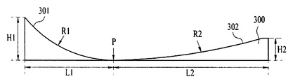
図2は、本実施例に係るリフレクタ支持部300の上部斜視図であり、図3は、本実施例に係るリフレクタ支持部300の正面図である。
FIG. 2 is a top perspective view of the
リフレクタ支持部300は、少なくとも1つの変曲点Pを中心に隣接する少なくとも2個の第1及び第2傾斜面301、302を備える。また、リフレクタ支持部300は、第1及び第2傾斜面301、302を支持するように、傾斜面の下部に支持脚310をさらに備えることができる。すなわち、本実施例によれば、図2及び図3に示すように、リフレクタ支持部300は、二つの変曲点Pがあり、各変曲点を中心に互いに隣接する第1傾斜面301と第2傾斜面302を有する。これに限定されず、他の実施例では、リフレクタ支持部300は、本実施例よりも多い傾斜面を有してもよく、少ない傾斜面を有してもよい。
The
支持脚310は、リフレクタ支持部300の底面305の背面に配置され、第1及び第2傾斜面301及び302を有するリフレクタ支持部300が垂れないないように支える役割を果たす。
The
また、リフレクタ支持部300の両端部に第1締結部320が設けられ、後述されるように、第1締結部320によりリフレクタ支持部300はカバープレート200に固定される。
Moreover, the
図4は、図1におけるA部分を拡大した斜視図である。 FIG. 4 is an enlarged perspective view of a portion A in FIG.
図4に示すように、カバープレート200は、光学部材支持部210を備え、カバープレート200の側面に少なくとも1つの光源モジュール400が配置されている。
As shown in FIG. 4, the
カバープレート200の光学部材支持部210の背面には、第1リフレクタ250が配置されてもよい。第1リフレクタ250は、光源モジュール400の一側面に配置できる。第1リフレクタ250は、反射コーティングフィルム及び反射コーティング物質のいずれか1つで形成され、光源モジュール400から生成された光をリフレクタ支持部300の方向に反射させる役割を果たすことができる。
A
また、第1リフレクタ250の表面のうち、発光モジュール400に相対する表面上には、鋸歯状の反射パターンが形成され、反射パターンの表面は平面または曲面であればよい。
Further, a sawtooth-like reflection pattern is formed on the surface of the
第1リフレクタ250の表面に反射パターンを形成する理由は、光源モジュール400で生成された光をリフレクタ支持部300の中央領域に反射させることによって、バックライトユニットの中央領域の輝度を増大させるためである。
The reason for forming the reflection pattern on the surface of the
光源モジュール400は、第1リフレクタ250とリフレクタ支持部300との間に配置され、第1リフレクタ250及び/またはリフレクタ支持部300に隣接して配置されるとよい。
The
場合によって、光源モジュール400は、第1リフレクタ250に接触すると同時に、リフレクタ支持部300から一定間隔離隔して配置されてもよく、リフレクタ支持部300に接触すると同時に、第1リフレクタ250から一定間隔離隔して配置されてもよい。
In some cases, the
または、光源モジュール400は、第1リフレクタ250及びリフレクタ支持部300の両方から一定間隔離隔して配置されてもよく、第1リフレクタ250及びリフレクタ支持部300の両方と接触して配置されてもよい。
Alternatively, the
リフレクタ支持部300は、第1リフレクタ250の表面に平行な水平面から一定角度で傾斜する傾斜面を有することができる。
The
図5は、実施例に係るカバープレート200とリフレクタ支持部300との結合構造を概略的に示す部分断面図である。
FIG. 5 is a partial cross-sectional view schematically showing a coupling structure between the
図5に示すように、リフレクタ支持部300の第1締結部320は、一定パターンの溝を有している。第1締結部320の溝パターンに対応する突起270a及び270bがカバープレート200に形成されている。したがって、リフレクタ支持部300の溝にカバープレート200の突起270a及び270bを挿着することで、リフレクタ支持部300をカバープレート200に固着できる。
As shown in FIG. 5, the
他の実施例によれば、カバープレート200とリフレクタ支持部300のそれぞれに通孔のような締結部を形成し、ねじのような別途の締結手段を通孔に挿入することによって、リフレクタ支持部300をカバープレート200に固着してもよい。
According to another embodiment, a fastening part such as a through hole is formed in each of the
図5を参照すると、光源モジュール400は、第1リフレクタ250と第2リフレクタ600との間においてカバープレート200に配置され、光を生成する少なくとも1つの光源(または、発光素子)402、及び電極パターンを有する回路基板404を備えることができる。
Referring to FIG. 5, the
ここで、光源402は、発光ダイオードチップ(LED chip)でよく、発光ダイオードチップは、ブルーLEDチップまたは紫外線LEDチップで構成されてもよく、レッドLEDチップ、グリーンLEDチップ、ブルーLEDチップ、イエローグリーン(Yellow green)LEDチップ、ホワイトLEDチップの少なくとも1つ又は2以上を組み合わせたパッケージ形態にしてもよい。
Here, the
そして、ホワイトLEDは、ブルーLED上に、イエロー燐光物質を結合して具現してもよく、ブルーLED上にレッド燐光物質及びグリーン燐光物質を同時に結合して具現してもよく、ブルーLED上にイエロー燐光物質、レッド燐光物質及びグリーン燐光物質を同時に結合して具現してもよい。 The white LED may be realized by combining a yellow phosphor on a blue LED, or may be realized by simultaneously combining a red phosphor and a green phosphor on a blue LED. A yellow phosphor, a red phosphor and a green phosphor may be combined at the same time.
回路基板404に少なくとも1つの光源402が実装されればよく、電源を供給するアダプタと光源402とを連結するための電極パターン(図示せず)が形成されていればよい。
It suffices that at least one
例えば、回路基板404の上面には、光源402とアダプタとを連結するための炭素ナノチューブ電極パターンを形成できる。
For example, a carbon nanotube electrode pattern for connecting the
このような回路基板404は、ポリエチレンテレフタレート(PET)、ガラス、ポリカーボネート(PC)またはシリコン(Si)などからなり、複数の光源402が実装される印刷回路基板(PCB:Printed Circuit Board)でよく、フィルム形態にしてもよい。
Such a
また、回路基板404には、単層PCB、多層PCB、セラミック基板、メタルコアPCBなどを選択的に用いることができる。
As the
一方、リフレクタ支持部300の第1及び第2傾斜面301及び302に接して第2リフレクタ600を配置できる。すなわち、リフレクタ支持部300の傾斜面構造と第2リフレクタ600の傾斜面構造とが一致してもよい。第2リフレクタ600は反射シートの形態にするとよい。
Meanwhile, the
これにより、カバープレート200に配置された光源モジュール400で生成された光が、リフレクタ支持部300の上部に配置された第2リフレクタ600で反射されてカバープレート200のオープン領域へと進むことが可能になる。
As a result, the light generated by the
第1リフレクタ250と第2リフレクタ600とは、光源モジュール400を間において空間を有するように一定間隔離隔して配置され、これでエアーガイド(air guide)構造を形成できる。
The
以下、リフレクタ支持部300の傾斜面について、添付の図面を参照して説明する。
Hereinafter, the inclined surface of the
図6及び図7は、リフレクタ支持部300の形状を説明するための断面図である。図6及び図7に示すように、変曲点Pを中心に隣接する第1及び第2傾斜面301及び302のそれぞれの第1及び第2曲率半径R1及びR2は、互いに異なってもよい。
6 and 7 are cross-sectional views for explaining the shape of the
そして、第1及び第2傾斜面301及び302との間の変曲点Pは、光源モジュール400に隣接して位置してもよく、光源モジュール400から遠く離れて位置してもよい。
The inflection point P between the first and second
第1傾斜面301は、第2傾斜面302に比べて光源モジュール400とより近接して配置されている。したがって、第1傾斜面301の第1曲率半径R1が第2傾斜面302の第2曲率半径R2よりも小さいと、変曲点Pは、光源モジュール400に近接するリフレクタ支持部300の領域に位置するはずである。一方、光源モジュール400に近接する第1傾斜面301の第1曲率半径R1が第2傾斜面302の第2曲率半径R2よりも大きいと、変曲点Pは、光源モジュール400から遠く離れたリフレクタ支持部300の領域に位置するはずである。
The first
このように、第1傾斜面301の第1曲率半径R1は第2傾斜面302の第2曲率半径R2と異なることがある。勿論、第1傾斜面301の第1曲率半径R1を第2傾斜面302の第2曲率半径R2と同一にしてもよい。
Thus, the first curvature radius R1 of the first
一方、第1傾斜面301の最高高さH1は、第2傾斜面302の最高高さH2と同一であっても異なってもよい。
On the other hand, the maximum height H1 of the first
例えば、図6に示すように、第1傾斜面301の第1曲率半径R1を第2傾斜面302の第2曲率半径R2よりも小さくし、第1傾斜面301の最高高さH1と第2傾斜面302の最高高さH2とを同一にし、変曲点Pから第1傾斜面301の先端までの距離L1を、変曲点Pから第2傾斜面302の先端までの距離L2よりも小さくしてもよい。
For example, as shown in FIG. 6, the first curvature radius R1 of the first
または、図7に示すように、第1傾斜面301の第1曲率半径R1を第2傾斜面302の第2曲率半径R2よりも小さくし、第1傾斜面301の最高高さH1は第2傾斜面302の最高高さH2よりも大きくし、変曲点Pから第1傾斜面301の先端までの距離L1を、変曲点Pから第2傾斜面302の先端までの距離L2より小さくしてもよい。
Alternatively, as shown in FIG. 7, the first curvature radius R1 of the first
リフレクタ支持部300を備えるバックライトユニットについて、より詳細に説明すると、下記の通りである。
The backlight unit including the
図8は、本実施例に係るバックライトユニットの断面図である。 FIG. 8 is a cross-sectional view of the backlight unit according to the present embodiment.
図8に示すように、光源モジュール400に隣接した第1傾斜面301の第1曲率半径R1は、第2傾斜面302の第2曲率半径R2より小さくても、大きくてもよい。
As shown in FIG. 8, the first curvature radius R1 of the first
場合によって、第1傾斜面301の第1曲率半径R1は、第2傾斜面302の第2曲率半径R2と同一であってもよい。
In some cases, the first curvature radius R1 of the first
ここで、第1傾斜面301の第1曲率半径R1と第2傾斜面302の第2曲率半径R2との比は、1:0.1〜10でよい。
Here, the ratio between the first curvature radius R1 of the first
そして、変曲点Pを通る第1水平線と第1傾斜面301の先端の一点を通る第2水平線との間の第1距離値D1は、変曲点Pを通る第1水平線と第2傾斜面302の先端の一点を通る第3水平線との間の第2距離値D2と同一でよい。
The first distance value D1 between the first horizontal line passing through the inflection point P and the second horizontal line passing through one point of the tip of the first
場合によって、変曲点Pを通る第1水平線と第1傾斜面301の先端の一点を通る第2水平線との間の第1距離値D1は、変曲点Pを通る第1水平線と第2傾斜面302の先端の一点を通る第3水平線との間の第2距離値D2よりも小さくても、大きくてもよい。
In some cases, the first distance value D1 between the first horizontal line passing through the inflection point P and the second horizontal line passing through one point of the tip of the first
ここで、第1距離値D1と第2距離値D2との比は1:0.01〜5でよい。 Here, the ratio between the first distance value D1 and the second distance value D2 may be 1: 0.01-5.
なお、変曲点Pを通る第1垂直線と第1傾斜面301の先端の一点を通る第2垂直線との間の第3距離値D3は、変曲点Pを通る第1垂直線と第2傾斜面302の先端の一点を通る垂直線との間の第4距離値D4より小さくても、大きくてもよい。
The third distance value D3 between the first vertical line passing through the inflection point P and the second vertical line passing through one point at the tip of the first
場合によっては、変曲点Pを通る第1垂直線と第1傾斜面301の先端の一点を通る第2垂直線との間の第3距離値D3は、変曲点Pを通る第1垂直線と第2傾斜面302の先端の一点を通る垂直線との間の第4距離値D4と同一であってもよい。
In some cases, the third distance value D3 between the first vertical line passing through the inflection point P and the second vertical line passing through one point of the tip of the first
ここで、第3距離値D3と第4距離値D4との比は、1:0.05〜20でよい。 Here, the ratio of the third distance value D3 and the fourth distance value D4 may be 1: 0.05-20.
なお、変曲点Pを通る第1水平線と光源モジュール400の一点を通る第4水平線との間の第5距離値D5は、変曲点Pを通る第1水平線と第2傾斜面302の先端の一点を通る第3水平線との間の第2距離値D2と同一であってもよい。
The fifth distance value D5 between the first horizontal line passing through the inflection point P and the fourth horizontal line passing through one point of the
場合によっては、変曲点Pを通る第1水平線と光源モジュール400の一点を通る第4水平線との間の第5距離値D5は、変曲点Pを通る第1水平線と第2傾斜面302の先端の一点を通る第3水平線との間の第2距離値D2より大きくてもよい。
In some cases, the fifth distance value D5 between the first horizontal line passing through the inflection point P and the fourth horizontal line passing through one point of the
また、リフレクタ支持部300は、ボトムカバー100の中心を基準に対称な形状を有することができる。すなわち、図8に示すように、リフレクタ支持部300の第1及び第2傾斜面301及び302は、リフレクタ支持部300の中心を基準に対称となるように形成できる。
In addition, the
また、リフレクタ支持部300の中心領域は、膨らんだ曲面形状にしてもよい。場合によって、リフレクタ支持部300の中心領域は、平らな平面または凹んだ曲面形状にしてもよい。すなわち、リフレクタ支持部300の中心領域は、平らな平面、膨らんだ曲面、凹んだ曲面のいずれか一形状にしてもよく、多数の形状が含まれるようにしてもよい。
Further, the central region of the
図8を参照すると、光学部材500は、カバープレート200の光学部材支持部210に支持され、リフレクタ支持部300と相対するように配置されている。
Referring to FIG. 8, the
光学部材500は、少なくとも1つのシートからなり、拡散シート、プリズムシート、輝度強化シートなどを選択的に含むことができる。
The
拡散シートは、光源モジュールから出射した光を拡散させ、プリズムシートは、拡散された光を発光領域に導き、輝度拡散シートは輝度を強化させることができる。 The diffusion sheet diffuses the light emitted from the light source module, the prism sheet guides the diffused light to the light emitting region, and the luminance diffusion sheet can enhance the luminance.
そして、光学部材500の上部表面と下部表面の少なくとも一方には、光の均一な拡散のために凹凸形状を有してもよい。
In addition, at least one of the upper surface and the lower surface of the
図9は、本実施例に係るリフレクタ支持部300の下部斜視図である。
FIG. 9 is a lower perspective view of the
図9に示すように、リフレクタ支持部300は、支持脚310及び少なくとも1つの第2締結部330を備えることができる。これらの支持脚310及び第2締結部330は、リフレクタ支持部300の背面に形成されている。
As shown in FIG. 9, the
第2締結部330は、ボトムカバー100の底面に形成された第3締結部と結合して、リフレクタ支持部300をボトムカバー100に固定する役割を果たす。
The
本実施例によれば、第2締結部330は、リフレクタ支持部300の背面に形成された3個の嵌め突起330a、330b及び330cを備えることができる。
According to the present embodiment, the
本実施例によれば、複数個の嵌め突起330a、330b及び330cを、互いに異なる方向に突延するように配置できる。すなわち、図9に示すように、リフレクタ支持部300の支持脚310の中心部に位置している第1嵌め突起330aは、第1方向に突延され、支持脚310の両端に位置している第2及び第3嵌め突起330b及び330cは、第1方向と反対方向である第2方向に突延されるとよい。第1乃至第3嵌め突起330a乃至330cが嵌るとともに、ボトムカバー100に形成される第3締結部、例えば、嵌め溝については後述される。
According to the present embodiment, the plurality of
このように、第1嵌め突起330aの突延方向が第2及び第3嵌め突起330b及び330cの突延方向と互いに反対である理由は、リフレクタ支持部300が左右において垂れることなくボトムカバー100の底面により堅牢に固定させるためである。
As described above, the reason why the extending direction of the first
図9において、第2締結部330は、嵌め突起330a、330b及び330cの形状を有するが、他の実施例によれば、第2締結部330は通孔形状にし、ねじのような別の締結手段を用いてリフレクタ支持部300をボトムカバー100の底面に固定させてもよい。
In FIG. 9, the
図10は、本実施例に係るボトムカバー100の背面図であり、図11は、図10においてボトムカバー100とリフレクタ支持部300との結合部分を拡大して示す図である。
FIG. 10 is a rear view of the
図10に示すように、ボトムカバー100の背面にリフレクタ支持部300が複数個の第2締結部330を用いて固定される。
As shown in FIG. 10, the
ボトムカバー100とリフレクタ支持部300との結合部分を拡大した図11を参照すると、リフレクタ支持部300の第2締結部330を嵌め突起330a、330b及び330cの形態とし、ボトムカバー100の第3締結部を嵌め溝110の形態として底面に形成できる。このような嵌め突起330a、330b及び330cを嵌め溝110に挿嵌することで、リフレクタ支持部300をボトムカバー100に固定できる。
Referring to FIG. 11 in which the coupling portion between the
嵌め突起330の下部半分が三角形状になっているから、ボトムカバー100の上部底面にリフレクタ支持部300を位置合わせ、ボトムカバー100に向かってリフレクタ支持部300を押圧すると、嵌め突起330が嵌め溝110に滑りつつ挿入され、リフレクタ支持部300がボトムカバー100に固定される。
Since the lower half of the
本実施例によれば、このようにリフレクタ支持部300をボトムカバー100に結合させることによって、高強度で反射特性に優れたエアーガイドを有するバックライトユニットを提供でき、バックライトユニットの信頼性を向上させるこさができる。
According to the present embodiment, by connecting the
また、図1または図4に示すように、リフレクタ支持部300の上部に光学部材500を支持する少なくとも一つの支持ピン340が形成されてもよい。これは、光学部材500がリフレクタ支持部300から離隔しており、その離隔空間にエアーガイドが形成されるため、光学部材500の中心領域が下方に垂れることがあるわけである。ここで、支持ピン340は、リフレクタ支持部300に接触する下部面の面積を上部面の面積よりも広くする方がより安定的である。
Also, as shown in FIG. 1 or FIG. 4, at least one
さらに他の実施例は、上記の各実施例に記載されたバックライトユニット、例えば、第1、第2リフレクタ及び光源モジュール250、600及び400を含む表示装置、指示装置、照明システムに具体化でき、例えば、照明システムには、ランプ、街灯がある。
Still other embodiments can be embodied in the backlight units described in the above embodiments, for example, display devices, indicator devices, and illumination systems including the first and second reflector and
このような照明システムは、多数のLEDを集束して光を得る照明灯に用いることができ、特に、建物の天井や壁体内に埋め込まれて、シェードの開口部側が露出されるように装着できる埋め込み灯(ダウンライト)に用いることができる。 Such an illumination system can be used for an illuminating lamp that collects a large number of LEDs to obtain light, and is particularly embedded in a ceiling or wall of a building so that the opening side of the shade is exposed. It can be used for embedded lights (downlights).
以上では実施例を中心に説明してきたが、それらは単なる例示で、本発明を限定するためのものではない。したがって、本発明の属する分野における通常の知識を有する者には、本実施例の本質的な特性を逸脱しない範囲で、以上に例示していない種々の変形及び応用が可能であるということが理解されるであろう。例えば、実施例に具体的に示した各構成要素を変形して実施することができる。なお、それらの変形及び応用も、添付の請求の範囲で規定する本発明の範囲に含まれるものとして解釈すべきである。 Although the embodiments have been described above mainly, they are merely examples and are not intended to limit the present invention. Accordingly, those skilled in the art to which the present invention pertains can understand that various modifications and applications not exemplified above are possible without departing from the essential characteristics of the present embodiment. Will be done. For example, each component specifically shown in the embodiments can be modified and implemented. Such modifications and applications should be construed as being included in the scope of the present invention as defined in the appended claims.
Claims (23)
それぞれが、前記ボトムカバー上に配置され、少なくとも1つの変曲点を中心に隣接する少なくとも2個の第1及び第2傾斜面を有する複数のリフレクタ支持部と、
前記複数のリフレクタ支持部上に配置された第2リフレクタと、
前記第1リフレクタと前記第2リフレクタとの間に配置された光源モジュールと
を備える、バックライトユニット。 A first reflector and a bottom cover;
A plurality of reflector supports each having at least two first and second inclined surfaces disposed on the bottom cover and adjacent to each other around at least one inflection point;
A second reflector disposed on the plurality of reflector supports;
A backlight unit comprising: a light source module disposed between the first reflector and the second reflector.
前記リフレクタ支持部の上部に形成されて前記光学部材を支持する少なくとも1つの支持ピンと
をさらに備える、請求項2に記載のバックライトユニット。 An optical member opposed to the reflector support and supported by the cover plate;
The backlight unit according to claim 2, further comprising at least one support pin that is formed on an upper portion of the reflector support portion and supports the optical member.
前記リフレクタ支持部は前記ボトムカバーに前記締結部により固定されている、請求項1に記載のバックライトユニット。 At least one fastening portion is formed on the back surface of the reflector support portion and the bottom surface of the bottom cover,
The backlight unit according to claim 1, wherein the reflector support portion is fixed to the bottom cover by the fastening portion.
前記リフレクタ支持部の背面に形成された少なくとも1つの嵌め突起と、
前記嵌め突起が嵌挿され、前記ボトムカバーの底面に形成された少なくとも1つの嵌め溝とを備える、請求項7に記載のバックライトユニット。 The fastening portion is
At least one fitting protrusion formed on the back surface of the reflector support;
The backlight unit according to claim 7, further comprising at least one fitting groove formed on the bottom surface of the bottom cover, into which the fitting protrusion is inserted.
Applications Claiming Priority (2)
| Application Number | Priority Date | Filing Date | Title |
|---|---|---|---|
| KR1020110082167A KR101832313B1 (en) | 2011-08-18 | 2011-08-18 | Display apparatus |
| KR10-2011-0082167 | 2011-08-18 |
Publications (2)
| Publication Number | Publication Date |
|---|---|
| JP2013041804A true JP2013041804A (en) | 2013-02-28 |
| JP2013041804A5 JP2013041804A5 (en) | 2015-03-12 |
Family
ID=45571371
Family Applications (1)
| Application Number | Title | Priority Date | Filing Date |
|---|---|---|---|
| JP2012014221A Pending JP2013041804A (en) | 2011-08-18 | 2012-01-26 | Backlight unit and illumination system including the same |
Country Status (6)
| Country | Link |
|---|---|
| US (1) | US8944622B2 (en) |
| EP (1) | EP2560042B1 (en) |
| JP (1) | JP2013041804A (en) |
| KR (1) | KR101832313B1 (en) |
| CN (1) | CN102954397B (en) |
| TW (1) | TWI578066B (en) |
Families Citing this family (6)
| Publication number | Priority date | Publication date | Assignee | Title |
|---|---|---|---|---|
| KR101928357B1 (en) * | 2012-03-23 | 2018-12-12 | 엘지이노텍 주식회사 | illumination unit and display apparatus for using the same |
| US20150192824A1 (en) * | 2012-07-26 | 2015-07-09 | Sharp Kabushiki Kaisha | Display device and television reception device |
| KR102173659B1 (en) * | 2014-03-10 | 2020-11-04 | 삼성디스플레이 주식회사 | Display apparatus |
| KR20160022420A (en) * | 2014-08-19 | 2016-03-02 | 삼성디스플레이 주식회사 | Display device |
| KR102554267B1 (en) * | 2016-09-27 | 2023-07-12 | 엘지디스플레이 주식회사 | Display device |
| KR102533257B1 (en) | 2018-07-13 | 2023-05-17 | 삼성전자주식회사 | Reflective sheet and display apparatus having the same |
Citations (5)
| Publication number | Priority date | Publication date | Assignee | Title |
|---|---|---|---|---|
| JP2006040764A (en) * | 2004-07-28 | 2006-02-09 | Mitsubishi Electric Corp | Surface light source and liquid crystal display |
| JP2006106212A (en) * | 2004-10-01 | 2006-04-20 | Nippon Leiz Co Ltd | Backlight unit |
| US20070171676A1 (en) * | 2006-01-20 | 2007-07-26 | Hon Hai Precision Industry Co., Ltd. | Backlight module |
| JP2008191237A (en) * | 2007-02-01 | 2008-08-21 | Ips Alpha Technology Ltd | Liquid crystal display |
| JP2011523177A (en) * | 2008-06-04 | 2011-08-04 | スリーエム イノベイティブ プロパティズ カンパニー | Hollow backlight with tilted light source |
Family Cites Families (19)
| Publication number | Priority date | Publication date | Assignee | Title |
|---|---|---|---|---|
| KR100840715B1 (en) * | 2002-05-28 | 2008-06-23 | 삼성전자주식회사 | Back light assembly and liquid crystal display having the same |
| TW589494B (en) * | 2003-07-04 | 2004-06-01 | Au Optronics Corp | Direct type backlight module |
| KR101075593B1 (en) * | 2004-08-27 | 2011-10-20 | 삼성전자주식회사 | Back light assembly and direct type liquid crystal display having the same |
| KR20060047025A (en) * | 2004-11-12 | 2006-05-18 | 삼성전자주식회사 | A backlight assembly compring an improved supporting member and a flat display device provided with the same |
| KR20060074354A (en) * | 2004-12-27 | 2006-07-03 | 삼성전자주식회사 | Back light assembly and liquid crystal display device having the same |
| TWI254175B (en) * | 2005-01-19 | 2006-05-01 | Au Optronics Corp | Backlight modules |
| US7473019B2 (en) * | 2005-09-29 | 2009-01-06 | Osram Opto Semiconductors Gmbh | Lighting apparatus |
| CN101004515A (en) * | 2006-01-21 | 2007-07-25 | 鸿富锦精密工业(深圳)有限公司 | Full run-down type backlight module |
| KR101274023B1 (en) * | 2006-04-12 | 2013-06-12 | 엘지디스플레이 주식회사 | A Direct Type Back-light Assembly |
| CN101165566A (en) * | 2006-10-20 | 2008-04-23 | 鸿富锦精密工业(深圳)有限公司 | Direct type backlight module group |
| TWI359988B (en) * | 2007-04-13 | 2012-03-11 | Chimei Innolux Corp | Liquid crystal display and backlight module thereo |
| KR101502914B1 (en) * | 2008-04-11 | 2015-03-16 | 삼성디스플레이 주식회사 | Backlight assembly, liquid crystal display having the same and method of fabricating the same |
| EP3193101A1 (en) * | 2008-07-09 | 2017-07-19 | Skyfuel, Inc. | Solar collectors having slidably removable reflective panels for use in solar thermal applications |
| US8376578B2 (en) * | 2009-06-12 | 2013-02-19 | Lg Innotek Co., Ltd. | Lighting device |
| EP2479478A4 (en) * | 2009-09-16 | 2013-08-28 | Sharp Kk | Lighting device, display apparatus, and television receiver |
| WO2011033900A1 (en) * | 2009-09-16 | 2011-03-24 | シャープ株式会社 | Illumination device, display device and television reception device |
| AU2010296606B2 (en) * | 2009-09-16 | 2013-02-28 | Sharp Kabushiki Kaisha | Lighting device, display device, and television receiver |
| KR101621540B1 (en) * | 2009-09-17 | 2016-05-31 | 엘지디스플레이 주식회사 | Liquid crystal display device |
| CN101794017B (en) * | 2010-03-02 | 2011-09-28 | 天津市太阳神科技有限公司 | Thin film solar reflecting and condensing device |
-
2011
- 2011-08-18 KR KR1020110082167A patent/KR101832313B1/en active IP Right Grant
-
2012
- 2012-01-19 EP EP12151798.1A patent/EP2560042B1/en active Active
- 2012-01-20 US US13/354,588 patent/US8944622B2/en active Active
- 2012-01-20 TW TW101102389A patent/TWI578066B/en active
- 2012-01-26 JP JP2012014221A patent/JP2013041804A/en active Pending
- 2012-01-31 CN CN201210021410.5A patent/CN102954397B/en active Active
Patent Citations (5)
| Publication number | Priority date | Publication date | Assignee | Title |
|---|---|---|---|---|
| JP2006040764A (en) * | 2004-07-28 | 2006-02-09 | Mitsubishi Electric Corp | Surface light source and liquid crystal display |
| JP2006106212A (en) * | 2004-10-01 | 2006-04-20 | Nippon Leiz Co Ltd | Backlight unit |
| US20070171676A1 (en) * | 2006-01-20 | 2007-07-26 | Hon Hai Precision Industry Co., Ltd. | Backlight module |
| JP2008191237A (en) * | 2007-02-01 | 2008-08-21 | Ips Alpha Technology Ltd | Liquid crystal display |
| JP2011523177A (en) * | 2008-06-04 | 2011-08-04 | スリーエム イノベイティブ プロパティズ カンパニー | Hollow backlight with tilted light source |
Also Published As
| Publication number | Publication date |
|---|---|
| KR20130019884A (en) | 2013-02-27 |
| KR101832313B1 (en) | 2018-04-04 |
| CN102954397A (en) | 2013-03-06 |
| TWI578066B (en) | 2017-04-11 |
| TW201310134A (en) | 2013-03-01 |
| EP2560042A1 (en) | 2013-02-20 |
| US8944622B2 (en) | 2015-02-03 |
| US20130044460A1 (en) | 2013-02-21 |
| EP2560042B1 (en) | 2016-04-06 |
| CN102954397B (en) | 2017-12-05 |
Similar Documents
| Publication | Publication Date | Title |
|---|---|---|
| US8235540B2 (en) | Backlight unit and display apparatus using the same | |
| TWI546593B (en) | Backlight unit and display device using the same | |
| US8926128B2 (en) | Light unit and illumination system using the same | |
| US8807772B2 (en) | Backlight unit, display device therewith, and lighting systems therewith | |
| TWI528082B (en) | Lighting system and display apparatus using the same | |
| TWI569072B (en) | Illumination unit and illumination system using the same | |
| JP6116805B2 (en) | Backlight unit, display device using the same, and illumination system including the same | |
| JP2013041804A (en) | Backlight unit and illumination system including the same | |
| JP2013008662A (en) | Backlight unit and display device using the same | |
| KR20130063773A (en) | Backlight unit, display apparatus using the same, and lighting system including the same | |
| TWI652531B (en) | Lighting system | |
| KR101948144B1 (en) | backlight unit and illumination system using the same | |
| JP5455084B2 (en) | Backlight unit and display device using the same | |
| KR20130019885A (en) | Backlight unit and display device including the same | |
| KR101948142B1 (en) | backlight unit and illumination system using the same | |
| KR101868538B1 (en) | Backlight unit, display apparatus using the same, and lighting apparatus including the same | |
| KR101933998B1 (en) | backlight unit and illumination system using the same | |
| KR20130063931A (en) | Backlight unit, display apparatus using the same, and lighting apparatus including the same | |
| KR20130066955A (en) | Backlight unit, display apparatus using the same, and lighting system including the same |
Legal Events
| Date | Code | Title | Description |
|---|---|---|---|
| A521 | Written amendment |
Free format text: JAPANESE INTERMEDIATE CODE: A523 Effective date: 20150123 |
|
| A621 | Written request for application examination |
Free format text: JAPANESE INTERMEDIATE CODE: A621 Effective date: 20150123 |
|
| A977 | Report on retrieval |
Free format text: JAPANESE INTERMEDIATE CODE: A971007 Effective date: 20151105 |
|
| A131 | Notification of reasons for refusal |
Free format text: JAPANESE INTERMEDIATE CODE: A131 Effective date: 20151110 |
|
| A521 | Written amendment |
Free format text: JAPANESE INTERMEDIATE CODE: A523 Effective date: 20160209 |
|
| A02 | Decision of refusal |
Free format text: JAPANESE INTERMEDIATE CODE: A02 Effective date: 20160614 |