JP2013017160A - Camera and interchangeable lens mountable on camera - Google Patents

Camera and interchangeable lens mountable on camera Download PDF

Info

Publication number
JP2013017160A
JP2013017160A JP2012123252A JP2012123252A JP2013017160A JP 2013017160 A JP2013017160 A JP 2013017160A JP 2012123252 A JP2012123252 A JP 2012123252A JP 2012123252 A JP2012123252 A JP 2012123252A JP 2013017160 A JP2013017160 A JP 2013017160A
Authority
JP
Japan
Prior art keywords
interchangeable lens
lens
zoom
controller
sound
Prior art date
Legal status (The legal status is an assumption and is not a legal conclusion. Google has not performed a legal analysis and makes no representation as to the accuracy of the status listed.)
Pending
Application number
JP2012123252A
Other languages
Japanese (ja)
Other versions
JP2013017160A5 (en
Inventor
Yasuo Otsuka
泰雄 大塚
Current Assignee (The listed assignees may be inaccurate. Google has not performed a legal analysis and makes no representation or warranty as to the accuracy of the list.)
Panasonic Corp
Original Assignee
Panasonic Corp
Priority date (The priority date is an assumption and is not a legal conclusion. Google has not performed a legal analysis and makes no representation as to the accuracy of the date listed.)
Filing date
Publication date
Application filed by Panasonic Corp filed Critical Panasonic Corp
Priority to JP2012123252A priority Critical patent/JP2013017160A/en
Publication of JP2013017160A publication Critical patent/JP2013017160A/en
Publication of JP2013017160A5 publication Critical patent/JP2013017160A5/ja
Pending legal-status Critical Current

Links

Images

Classifications

    • GPHYSICS
    • G03PHOTOGRAPHY; CINEMATOGRAPHY; ANALOGOUS TECHNIQUES USING WAVES OTHER THAN OPTICAL WAVES; ELECTROGRAPHY; HOLOGRAPHY
    • G03BAPPARATUS OR ARRANGEMENTS FOR TAKING PHOTOGRAPHS OR FOR PROJECTING OR VIEWING THEM; APPARATUS OR ARRANGEMENTS EMPLOYING ANALOGOUS TECHNIQUES USING WAVES OTHER THAN OPTICAL WAVES; ACCESSORIES THEREFOR
    • G03B17/00Details of cameras or camera bodies; Accessories therefor
    • G03B17/02Bodies
    • G03B17/12Bodies with means for supporting objectives, supplementary lenses, filters, masks, or turrets
    • G03B17/14Bodies with means for supporting objectives, supplementary lenses, filters, masks, or turrets interchangeably
    • GPHYSICS
    • G03PHOTOGRAPHY; CINEMATOGRAPHY; ANALOGOUS TECHNIQUES USING WAVES OTHER THAN OPTICAL WAVES; ELECTROGRAPHY; HOLOGRAPHY
    • G03BAPPARATUS OR ARRANGEMENTS FOR TAKING PHOTOGRAPHS OR FOR PROJECTING OR VIEWING THEM; APPARATUS OR ARRANGEMENTS EMPLOYING ANALOGOUS TECHNIQUES USING WAVES OTHER THAN OPTICAL WAVES; ACCESSORIES THEREFOR
    • G03B2206/00Systems for exchange of information between different pieces of apparatus, e.g. for exchanging trimming information, for photo finishing
    • GPHYSICS
    • G03PHOTOGRAPHY; CINEMATOGRAPHY; ANALOGOUS TECHNIQUES USING WAVES OTHER THAN OPTICAL WAVES; ELECTROGRAPHY; HOLOGRAPHY
    • G03BAPPARATUS OR ARRANGEMENTS FOR TAKING PHOTOGRAPHS OR FOR PROJECTING OR VIEWING THEM; APPARATUS OR ARRANGEMENTS EMPLOYING ANALOGOUS TECHNIQUES USING WAVES OTHER THAN OPTICAL WAVES; ACCESSORIES THEREFOR
    • G03B31/00Associated working of cameras or projectors with sound-recording or sound-reproducing means
    • HELECTRICITY
    • H04ELECTRIC COMMUNICATION TECHNIQUE
    • H04NPICTORIAL COMMUNICATION, e.g. TELEVISION
    • H04N23/00Cameras or camera modules comprising electronic image sensors; Control thereof
    • H04N23/60Control of cameras or camera modules
    • H04N23/66Remote control of cameras or camera parts, e.g. by remote control devices
    • H04N23/663Remote control of cameras or camera parts, e.g. by remote control devices for controlling interchangeable camera parts based on electronic image sensor signals
    • HELECTRICITY
    • H04ELECTRIC COMMUNICATION TECHNIQUE
    • H04NPICTORIAL COMMUNICATION, e.g. TELEVISION
    • H04N23/00Cameras or camera modules comprising electronic image sensors; Control thereof
    • H04N23/60Control of cameras or camera modules
    • H04N23/69Control of means for changing angle of the field of view, e.g. optical zoom objectives or electronic zooming

Abstract

PROBLEM TO BE SOLVED: To provide a camera and an interchangeable lens capable of reliably giving a sensation of acoustic zoom effect to a user regardless of the type (focal distance) of the interchangeable lens.SOLUTION: A camera (102) includes: a receiver section (130) that receives a piece of zoom range information representing a range of zoom magnification available by an interchangeable lens (301) from the interchangeable lens (301); a sound collection section (111) that generates a piece of voice data from a voice; and a voice processing section (120) that changes the setting of directional characteristics of the sound collection section (111) corresponding to the zoom magnification of the interchangeable lens (301). The voice processing section (120) sets the sound collection section (111) to first directional characteristics in which a voice in a widest region can be collected when the interchangeable lens (301) is at a position where minimum zoom magnification is obtained and to second directional characteristics in which a voice in a narrowest region can be collected when the interchangeable lens (301) is at a position at which maximum zoom magnification is obtained, on the basis of the zoom range information.

Description

ここに開示された技術は、音声記録機能を備えるカメラ本体、およびそのようなカメラ本体に装着可能な交換レンズに関する。   The technology disclosed herein relates to a camera body having an audio recording function, and an interchangeable lens that can be attached to such a camera body.

近年、画像データと共に音声データを記録できる撮像装置が普及してきている。こうした音声記録機能を備える撮像装置において、レンズの焦点距離(ズーム位置)情報に基づいてマイクロホンの指向性を調節することにより、収音する範囲を変更する機能(音響的ズーム機能)を実現する技術が知られている(例えば、特許文献1参照)。また、レンズ交換可能な撮像装置において、交換レンズの焦点距離情報に基づいてマイクロホンの指向性を制御する技術が知られている(例えば、特許文献2参照)。   In recent years, imaging apparatuses capable of recording audio data together with image data have become widespread. Technology for realizing a function (acoustic zoom function) for changing a sound collection range by adjusting the directivity of a microphone based on focal length (zoom position) information of a lens in an imaging apparatus having such a sound recording function. Is known (see, for example, Patent Document 1). In addition, a technique for controlling the directivity of a microphone based on focal length information of an interchangeable lens in an image-capable imaging device is known (see, for example, Patent Document 2).

特開平8−182091号公報JP-A-8-182091 特開2010−200253号公報JP 2010-200263 A

特許文献2に記載された従来の撮像装置は、装着された交換レンズにおいて設定可能な焦点距離の範囲に関わらず、交換レンズの設定された焦点距離に基づいてマイクロホンの指向性の度合いを決定する。このため、撮像装置に装着された交換レンズの種類によっては、使用者に音響ズーム(音響的ズーム効果)を体感させにくいという問題があった。これは、特許文献2記載の撮像装置では、交換レンズの焦点距離範囲に依存して指向性の変化の範囲が決まるからである。つまり、焦点距離の範囲が小さいレンズが装着されたときは、焦点距離の範囲が大きいレンズが装着されたときよりも、指向性の変化の範囲が小さくなるということがあった。   The conventional imaging device described in Patent Document 2 determines the degree of directivity of the microphone based on the set focal length of the interchangeable lens, regardless of the range of the focal length that can be set in the attached interchangeable lens. . Therefore, depending on the type of interchangeable lens attached to the imaging apparatus, there is a problem that it is difficult for the user to experience acoustic zoom (acoustic zoom effect). This is because in the imaging apparatus described in Patent Document 2, the range of directivity change is determined depending on the focal length range of the interchangeable lens. In other words, when a lens with a small focal length range is attached, the range of change in directivity may be smaller than when a lens with a large focal length range is attached.

本発明はこのような問題を鑑みてなされたものであり、その目的は、交換レンズの種類(焦点距離)に関わらず、使用者に音響ズーム効果をより確実に体感させることが可能なカメラ本体および交換レンズを提供することである。   The present invention has been made in view of such a problem, and an object of the present invention is to make it possible for the user to more reliably experience the acoustic zoom effect regardless of the type (focal length) of the interchangeable lens. And providing interchangeable lenses.

本発明に係るカメラ本体は、ズーム倍率が可変の交換レンズを装着可能なカメラ本体である。カメラ本体は、交換レンズが取りうるズーム倍率の範囲を示す情報であるズーム範囲情報を、交換レンズから受信する受信部と、音声を収音して音声データを生成する収音部と、交換レンズのズーム倍率と連動して、収音部の指向特性に関する設定を変更する音声処理部とを備える。ズーム範囲情報は交換レンズがとり得る最大倍率および最小倍率に対応する情報を含む。収音部の指向特性は、最も幅の広い領域の音声の収音を可能とする第1の指向特性から、最も幅の狭い領域の音声の収音を可能とする第2の指向特性の間で変更可能である。音声処理部は、ズーム範囲情報に基づいて、交換レンズがズームの最小倍率を与える位置にあるときは収音部の指向特性を第1の指向特性に設定し、交換レンズがズームの最大倍率を与える位置にあるときは収音部の指向特性を第2の指向特性に設定する。   The camera body according to the present invention is a camera body to which an interchangeable lens having a variable zoom magnification can be attached. The camera body includes a receiving unit that receives zoom range information, which is information indicating a range of zoom magnification that the interchangeable lens can take, from the interchangeable lens, a sound collecting unit that collects sound and generates audio data, and an interchangeable lens. And an audio processing unit that changes the setting relating to the directivity of the sound collection unit in conjunction with the zoom magnification. The zoom range information includes information corresponding to the maximum magnification and the minimum magnification that the interchangeable lens can take. The directivity characteristic of the sound collection unit is between the first directivity characteristic that enables sound collection in the widest area and the second directivity characteristic that enables sound collection in the narrowest area. Can be changed. Based on the zoom range information, the sound processing unit sets the directivity characteristic of the sound collection unit to the first directivity characteristic when the interchangeable lens is at a position that gives the minimum zoom magnification, and the interchangeable lens sets the maximum zoom magnification. When the position is given, the directivity of the sound collection unit is set to the second directivity.

また、本発明に係る交換レンズは、カメラ本体に装着可能な交換レンズである。交換レンズは、ズーム範囲情報を記憶している記憶部と、ズーム範囲情報をカメラ本体に送信する送信部とを備える。   The interchangeable lens according to the present invention is an interchangeable lens that can be attached to the camera body. The interchangeable lens includes a storage unit that stores zoom range information and a transmission unit that transmits the zoom range information to the camera body.

本発明に係るカメラ本体および交換レンズによれば、交換レンズの種類(焦点距離)に関わらず、使用者に音響ズームをより確実に体感させることが可能である。   According to the camera body and the interchangeable lens according to the present invention, it is possible to cause the user to experience acoustic zoom more reliably regardless of the type (focal length) of the interchangeable lens.

本実施形態のデジタルカメラの斜視図The perspective view of the digital camera of this embodiment 本実施形態のデジタルカメラの背面図Rear view of the digital camera of this embodiment 本実施形態のデジタルカメラの電気的な構成を示すブロック図Block diagram showing the electrical configuration of the digital camera of the present embodiment 本実施形態のデジタルカメラの電源投入時の初期動作を説明するためのフローチャートFlowchart for explaining an initial operation when the digital camera according to this embodiment is turned on. 本実施形態のデジタルカメラの動画撮影モードでの動作を説明するためのフローチャートThe flowchart for demonstrating the operation | movement in the video recording mode of the digital camera of this embodiment. 音響ワイド端でのマイクロホン部の指向特性を示す図The figure which shows the directional characteristic of the microphone section at the acoustic wide end 音響テレ端でのマイクロホン部の指向特性を示す図The figure which shows the directivity characteristic of the microphone section at the acoustic tele end 本実施形態のデジタルカメラの音声記録動作を説明するためのフローチャートFlow chart for explaining the sound recording operation of the digital camera of the present embodiment. 交換レンズの焦点距離と音声信号に付与される音響ズームとの関係を説明するためのグラフGraph for explaining the relationship between the focal length of the interchangeable lens and the acoustic zoom applied to the audio signal

以下、添付の図面を参照して実施形態を説明する。
なお、参照する図面において、同一又は類似の部分には、同一又は類似の符号を付している。ただし、図面は模式的なものであり、各寸法の比率等は現実のものとは異なっている場合がある。したがって、具体的な寸法等は本明細書の説明を参酌して判断されるべきである。また、図面相互間においても互いの寸法の関係や比率が異なる部分が含まれていることは勿論である。
Hereinafter, embodiments will be described with reference to the accompanying drawings.
In the drawings to be referred to, the same or similar parts are denoted by the same or similar reference numerals. However, the drawings are schematic, and the ratio of each dimension may be different from the actual one. Therefore, specific dimensions and the like should be determined in consideration of the description of this specification. Moreover, it is a matter of course that portions having different dimensional relationships and ratios are included between the drawings.

以下の実施形態では、音声記録機能を備えるカメラ本体および該カメラ本体に装着可能な交換レンズとして、デジタルカメラを例に挙げて説明する。   In the following embodiments, a digital camera will be described as an example of a camera body having an audio recording function and an interchangeable lens that can be attached to the camera body.

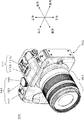
また、以下の説明では、図1で示すデジタルカメラ100を基準として、被写体に向かう方向を「前方」、その反対側の方向を「後方」、操作部180やマイクロホン部111が配置された面がある方向を「上方」、上方とは逆の方向を「下方」、左マイクロホン111Lから右マイクロホン111Rが設置された位置への方向を「右方」、右方とは逆の方向を「左方」とする。また、デジタルカメラ100の下方が鉛直方向と一致するデジタルカメラ100の姿勢を、デジタルカメラ100の「通常姿勢」または「横撮り姿勢」という。   In the following description, with reference to the digital camera 100 shown in FIG. 1, the direction toward the subject is “front”, the opposite direction is “rear”, and the surface on which the operation unit 180 and the microphone unit 111 are arranged. One direction is “upward”, the opposite direction is “downward”, the direction from the left microphone 111L to the position where the right microphone 111R is installed is “right”, and the direction opposite to the right is “left” " Further, the posture of the digital camera 100 in which the lower side of the digital camera 100 coincides with the vertical direction is referred to as “normal posture” or “horizontal shooting posture” of the digital camera 100.

<1.構成>
<1−1.デジタルカメラの全体構成>
図1を参照して、本実施形態のデジタルカメラ100の全体的な構成について説明する。デジタルカメラ100はカメラボディ102と交換レンズ301とで構成される。カメラボディ102は操作部180とマイクロホン部111とを備える。操作部180はレリーズ釦181と、電源スイッチ183と、モードダイヤル184とを含み、カメラボディ102の上面に設置される。マクロホン部111は左マイクロホン111Lおよび右マイクロホン111Rの2つのマイクロホンを含む。左マイクロホン111Lおよび右マイクロホン111Rは、カメラボディ102の上面に、左右方向に並んで設置される。
<1. Configuration>
<1-1. Overall configuration of digital camera>
With reference to FIG. 1, the overall configuration of the digital camera 100 of the present embodiment will be described. The digital camera 100 includes a camera body 102 and an interchangeable lens 301. The camera body 102 includes an operation unit 180 and a microphone unit 111. The operation unit 180 includes a release button 181, a power switch 183, and a mode dial 184, and is installed on the upper surface of the camera body 102. The macrophone unit 111 includes two microphones, a left microphone 111L and a right microphone 111R. The left microphone 111L and the right microphone 111R are installed on the upper surface of the camera body 102 side by side in the left-right direction.

また、カメラボディ102は図2に示すように、その背面に中央釦185および十字釦186などの操作部180と、表示部190と、ビューファインダー191とを備える。表示部190は本実施形態では液晶ディスプレイであるが、他の表示デバイスが表示部190に用いられてもよい。   As shown in FIG. 2, the camera body 102 includes an operation unit 180 such as a center button 185 and a cross button 186, a display unit 190, and a viewfinder 191 on the back surface. The display unit 190 is a liquid crystal display in the present embodiment, but other display devices may be used for the display unit 190.

<1−2.交換レンズの構成>
図3を参照して交換レンズ301の構成について説明する。交換レンズ301は複数のレンズを有する。交換レンズ301は、レンズコントローラ320と、レンズマウント330と、フォーカスレンズ310およびズームレンズ312を含む光学系と、絞り316と、フォーカスレンズ駆動部311と、ズームレンズ駆動部313と、絞り駆動部317と、操作リング315と、DRAM321と、フラッシュメモリ322とを備える。
<1-2. Interchangeable lens configuration>
The configuration of the interchangeable lens 301 will be described with reference to FIG. The interchangeable lens 301 has a plurality of lenses. The interchangeable lens 301 includes a lens controller 320, a lens mount 330, an optical system including a focus lens 310 and a zoom lens 312, an aperture 316, a focus lens driving unit 311, a zoom lens driving unit 313, and an aperture driving unit 317. An operation ring 315, a DRAM 321, and a flash memory 322.

操作リング315は、交換レンズ301の外面に設置された操作部材である。操作リング315は、交換レンズ301に対して相対的に回転可能に設置される。操作リング315の回転位置や、回転速度は不図示の検出部により検出されて、レンズコントローラ320に通知される。   The operation ring 315 is an operation member installed on the outer surface of the interchangeable lens 301. The operation ring 315 is installed to be rotatable relative to the interchangeable lens 301. The rotation position and rotation speed of the operation ring 315 are detected by a detection unit (not shown) and notified to the lens controller 320.

レンズコントローラ320は、交換レンズ301の各部を制御する。レンズコントローラ320は、操作リング315および操作部180によって受け付けられた操作に基づいて、フォーカスレンズ駆動部311、ズームレンズ駆動部313および絞り駆動部に指示を出す。例えば、操作リング315から通知された回転位置や回転速度に基づいて、レンズコントローラ320はズームレンズ駆動部313に対して駆動制御信号を送信する。ズームレンズ駆動部313はこの駆動制御信号に従って、ズームレンズ312を駆動する。また、レンズコントローラ320は、DRAM321やフラッシュメモリ322に接続されているので、必要に応じて、DRAM321やフラッシュメモリ322に情報を書き込んだり、DRAM321やフラッシュメモリ322から情報を読み出したりすることが可能である。また、レンズコントローラ320は、レンズマウント330を通じて、コントローラ130と通信可能である。なお、コントローラ130は、ハードワイヤードな電子回路で構成してもよいし、プログラムを用いたマイクロ・コンピュータなどで構成してもよい。   The lens controller 320 controls each part of the interchangeable lens 301. The lens controller 320 issues an instruction to the focus lens driving unit 311, the zoom lens driving unit 313, and the aperture driving unit based on the operation received by the operation ring 315 and the operation unit 180. For example, the lens controller 320 transmits a drive control signal to the zoom lens driving unit 313 based on the rotation position and rotation speed notified from the operation ring 315. The zoom lens driving unit 313 drives the zoom lens 312 according to the drive control signal. Further, since the lens controller 320 is connected to the DRAM 321 and the flash memory 322, information can be written to the DRAM 321 and the flash memory 322 and information can be read from the DRAM 321 and the flash memory 322 as necessary. is there. The lens controller 320 can communicate with the controller 130 through the lens mount 330. The controller 130 may be configured with a hard-wired electronic circuit, or may be configured with a microcomputer using a program.

レンズマウント330は、カメラボディ102のボディマウント340(後述)と連携して、交換レンズ301をカメラボディ102へ機械的および電気的に接続する。この接続により、レンズコントローラ320およびコントローラ130は互いに通信可能な状態となる。   The lens mount 330 mechanically and electrically connects the interchangeable lens 301 to the camera body 102 in cooperation with a body mount 340 (described later) of the camera body 102. With this connection, the lens controller 320 and the controller 130 can communicate with each other.

DRAM321は、レンズコントローラ320が各種制御を実行する際のワークメモリとして使用される。また、フラッシュメモリ322は、レンズコントローラ320が各種制御を実行する際にレンズコントローラ320によって使用される、プログラムやパラメータ、レンズデータ等を格納している。   The DRAM 321 is used as a work memory when the lens controller 320 executes various controls. The flash memory 322 stores programs, parameters, lens data, and the like used by the lens controller 320 when the lens controller 320 executes various controls.

フォーカスレンズ310は、交換レンズ301を介してCCDイメージセンサ143上に形成される被写体像のフォーカス状態を変化させるためのレンズである。フォーカスレンズ駆動部311は、レンズコントローラ320から送信される制御信号に従って、フォーカスレンズ310が光学系の光軸に沿って進退するようにフォーカスレンズ310を駆動する。   The focus lens 310 is a lens for changing the focus state of the subject image formed on the CCD image sensor 143 via the interchangeable lens 301. The focus lens driving unit 311 drives the focus lens 310 according to a control signal transmitted from the lens controller 320 so that the focus lens 310 moves forward and backward along the optical axis of the optical system.

ズームレンズ312は、交換レンズ301の光学系で形成される被写体像の倍率を変化させるためのレンズである。ズームレンズ駆動部313は、レンズコントローラ320から送信される制御信号に従って、ズームレンズ312が光学系の光軸に沿って進退するようにズームレンズ312を駆動する。なお、ズームレンズ312およびフォーカスレンズ310それぞれのレンズ構成は何枚でも何群でもよい。   The zoom lens 312 is a lens for changing the magnification of a subject image formed by the optical system of the interchangeable lens 301. The zoom lens driving unit 313 drives the zoom lens 312 according to the control signal transmitted from the lens controller 320 so that the zoom lens 312 advances and retreats along the optical axis of the optical system. The zoom lens 312 and the focus lens 310 may have any number or number of lens configurations.

絞り316は、開閉可能な複数の機械羽根で構成される。絞り316は、CCDイメージセンサ143(後述)に入射する光量を調節するための調節部材である。絞り駆動部317は、レンズコントローラ320から送信される制御信号に従って、絞り316の機械羽根の開閉状態が変化するように絞り316を駆動する。なお、絞り駆動部317、フォーカスレンズ駆動部311およびズームレンズ駆動部313は、例えば、ステッピングモータやDCモータ、超音波モータなどにより実現できる。   The aperture 316 is composed of a plurality of mechanical blades that can be opened and closed. The diaphragm 316 is an adjustment member for adjusting the amount of light incident on a CCD image sensor 143 (described later). The aperture driving unit 317 drives the aperture 316 according to the control signal transmitted from the lens controller 320 so that the open / close state of the mechanical blades of the aperture 316 changes. The aperture driving unit 317, the focus lens driving unit 311 and the zoom lens driving unit 313 can be realized by, for example, a stepping motor, a DC motor, an ultrasonic motor, or the like.

<1−3.デジタルカメラボディの構成>
図3を参照して、カメラボディ102の構成について説明する。カメラボディ102はマイクロホン部111と、アナログ音声処理部115と、デジタル画像・音声処理部120と、コントローラ130と、CCDイメージセンサ143と、アナログ・フロント・エンド(AFE)144と、RAM150と、外部記憶媒体160と、ROM170と、操作部180と、表示部190と、ビューファインダー191と、スピーカー195と、ボディマウント340とを備える。
<1-3. Structure of digital camera body>
The configuration of the camera body 102 will be described with reference to FIG. The camera body 102 includes a microphone unit 111, an analog audio processing unit 115, a digital image / audio processing unit 120, a controller 130, a CCD image sensor 143, an analog front end (AFE) 144, a RAM 150, an external A storage medium 160, a ROM 170, an operation unit 180, a display unit 190, a viewfinder 191, a speaker 195, and a body mount 340 are provided.

なお、交換レンズ301とCCDイメージセンサ143とAFE144とをまとめて「画像入力系」140という。また、マイクロホン部111とアナログ音声処理部115とをまとめて「音声入力系」110という。なお、画像入力系140および音声入力系110はそれぞれ、他の構成要素を含んでもよい。   The interchangeable lens 301, the CCD image sensor 143, and the AFE 144 are collectively referred to as an “image input system” 140. Further, the microphone unit 111 and the analog audio processing unit 115 are collectively referred to as “audio input system” 110. Note that each of the image input system 140 and the audio input system 110 may include other components.

ボディマウント340は、交換レンズ301のレンズマウント330と連携して、カメラボディ102を交換レンズ301に接続し、コントローラ130をレンズコントローラ320と通信可能な状態にする。ボディマウント340は、コントローラ130から露光同期信号やその他制御信号を受信して、これらの信号をレンズマウント330経由でレンズコントローラ320に送信する。また、ボディマウント340は、レンズコントローラ320からレンズマウント330を通じて受信された信号を、コントローラ130に送信する。   The body mount 340 cooperates with the lens mount 330 of the interchangeable lens 301 to connect the camera body 102 to the interchangeable lens 301 so that the controller 130 can communicate with the lens controller 320. The body mount 340 receives an exposure synchronization signal and other control signals from the controller 130, and transmits these signals to the lens controller 320 via the lens mount 330. The body mount 340 transmits a signal received from the lens controller 320 through the lens mount 330 to the controller 130.

CCDイメージセンサ143は、交換レンズ301を通じて形成された被写体像を撮像して画像情報を生成する。CCDイメージセンサ143の受光面には、多数のフォトダイオードが2次元的に(マトリクス状に)配列される。また、各フォトダイオードに対応して、赤色(R)、緑色(G)および青色(B)の原色カラーフィルターが配置される。R、GおよびBの原色カラーフィルターは、所定の配列構造で配置される。撮像対象となる被写体からの光は、交換レンズ301を通過した後、CCDイメージセンサ143の受光面に結像される。結像された被写体像は、各フォトダイオードへ入射した光量に従って、R、GおよびBの色別に色情報に変換される。その結果、被写体像全体を示す画像情報が生成される。各フォトダイオードは、CCDイメージセンサ143の画素に対応する。しかし、各フォトダイオードから実際に出力される色情報は、R、G、Bのいずれかの原色情報である。そのため、各画素で発現されるべき色は、後段のデジタル画像・音声処理部120(後述)において、各画素に対応するフォトダイオードおよび、その周辺のフォトダイオードから出力される原色情報(色、光量)に基づき生成される。なお、CCDイメージセンサ143は、デジタルカメラ100が撮影モード(後述)にあるとき、一定時間ごとに新しいフレームの画像情報を生成する。   The CCD image sensor 143 captures a subject image formed through the interchangeable lens 301 and generates image information. A large number of photodiodes are arranged two-dimensionally (in a matrix) on the light receiving surface of the CCD image sensor 143. Further, primary color filters of red (R), green (G), and blue (B) are arranged corresponding to each photodiode. The primary color filters for R, G, and B are arranged in a predetermined arrangement structure. Light from the subject to be imaged passes through the interchangeable lens 301 and then forms an image on the light receiving surface of the CCD image sensor 143. The formed subject image is converted into color information for each of R, G, and B colors according to the amount of light incident on each photodiode. As a result, image information indicating the entire subject image is generated. Each photodiode corresponds to a pixel of the CCD image sensor 143. However, the color information actually output from each photodiode is R, G, or B primary color information. Therefore, the color to be expressed in each pixel is the primary color information (color, light amount) output from the photodiode corresponding to each pixel and the surrounding photodiodes in the subsequent digital image / sound processing unit 120 (described later). ). The CCD image sensor 143 generates image information of a new frame at regular intervals when the digital camera 100 is in a shooting mode (described later).

AFE144は、CCDイメージセンサ143によって生成された画像情報に対して相関二重サンプリングによる雑音抑圧や、アナログ・ゲイン・コントローラによるA/Dコンバータの入力レンジ幅への増幅、A/DコンバータによるA/D変換等を施す。その後、AFE144は、これらの処理が施された画像情報をデジタル画像・音声処理部120に出力する。   The AFE 144 performs noise suppression by correlated double sampling on the image information generated by the CCD image sensor 143, amplification to the input range width of the A / D converter by an analog gain controller, and A / D by the A / D converter. D conversion is performed. Thereafter, the AFE 144 outputs the image information subjected to these processes to the digital image / audio processing unit 120.

マイクロホン部111は、前述のとおりマイクロホン111L、111Rを含む。マイクロホン111L、111Rは、音声を電気信号である音声信号に変換して、この音声信号をアナログ音声処理部115に出力する。   The microphone unit 111 includes the microphones 111L and 111R as described above. The microphones 111 </ b> L and 111 </ b> R convert the sound into an audio signal that is an electrical signal, and output the audio signal to the analog audio processing unit 115.

アナログ音声処理部115は、入力された音声信号を処理し、この音声信号をA/DコンバータによってA/D変換し、デジタル画像・音声処理部120に出力する。   The analog audio processing unit 115 processes the input audio signal, A / D-converts this audio signal by an A / D converter, and outputs it to the digital image / audio processing unit 120.

デジタル画像・音声処理部120は、コントローラ130からの指示に従って、AFE144から出力された画像情報およびアナログ音声処理部115から出力された音声信号に対して各種の処理を施す。例えば、デジタル画像・音声処理部120はガンマ補正やホワイトバランス補正、傷補正、符号化処理等を画像情報に対して施す。また、デジタル画像・音声処理部120は、入力された音声信号を演算処理することにより、指向性合成処理を施す。指向性合成処理の詳細は後述する。   The digital image / sound processor 120 performs various processes on the image information output from the AFE 144 and the sound signal output from the analog sound processor 115 in accordance with instructions from the controller 130. For example, the digital image / audio processing unit 120 performs gamma correction, white balance correction, flaw correction, encoding processing, and the like on the image information. The digital image / sound processing unit 120 performs directivity synthesis processing by performing arithmetic processing on the input sound signal. Details of the directivity synthesis processing will be described later.

なお、デジタル画像・音声処理部120は、ハードワイヤードな電子回路で実現してもよいし、プログラムを実行するマイクロ・コンピュータなどで実現してもよい。デジタル画像・音声処理部120は、コントローラ130などと一体的に1つの半導体チップとして実現してもよい。   The digital image / sound processing unit 120 may be realized by a hard-wired electronic circuit or a microcomputer that executes a program. The digital image / audio processing unit 120 may be realized as one semiconductor chip integrally with the controller 130 or the like.

表示部190は、デジタル画像・音声処理部120にて処理された画像情報を表示する。表示部190が表示する画像には、スルー画像および再生画像などがある。表示部190が表示する画像は、デジタルカメラ100の動作モードによって異なる。   The display unit 190 displays the image information processed by the digital image / sound processing unit 120. The images displayed by the display unit 190 include a through image and a reproduced image. The image displayed on the display unit 190 varies depending on the operation mode of the digital camera 100.

デジタルカメラ100は、動作モードとして撮影モードおよび再生モードなどを有する。「撮影モード」は被写体像から得られた画像情報が外部記憶媒体160等に記録されるモードである。「再生モード」は、外部記憶媒体160等に記録されている画像情報が表示部190に表示されるモードである。   The digital camera 100 has a shooting mode, a playback mode, and the like as operation modes. The “shooting mode” is a mode in which image information obtained from the subject image is recorded in the external storage medium 160 or the like. “Reproduction mode” is a mode in which image information recorded in the external storage medium 160 or the like is displayed on the display unit 190.

デジタルカメラ100が撮影モードであり、かつ静止画撮影を行っていない待機状態(後述)または動画撮影状態(後述)にあるとき、表示部190はスルー画像を表示する。使用者は、表示部190に表示されるスルー画像を参照することにより、被写体の構図を確認しながら被写体を撮影できる。「スルー画像」は、CCDイメージセンサ143により一定時間ごとに生成されるフレーム画像に基づいてデジタル画像・音声処理部120によって生成される。スルー画像は外部記憶媒体160等に記録されない。   When the digital camera 100 is in a shooting mode and is in a standby state (described later) or a moving image shooting state (described later) in which still image shooting is not performed, the display unit 190 displays a through image. The user can photograph the subject while confirming the composition of the subject by referring to the through image displayed on the display unit 190. The “through image” is generated by the digital image / sound processor 120 based on the frame image generated by the CCD image sensor 143 at regular intervals. The through image is not recorded in the external storage medium 160 or the like.

また、デジタルカメラ100が再生モードにあるとき、表示部190は再生画像を表示する。「再生画像」は、外部記憶媒体160等に記録された画像情報に基づいて生成される。具体的には再生画像は、外部記憶媒体160等に記録された高解像度の記録画像をデジタル画像・音声処理部120が表示部190の解像度に下げることにより、生成される。   When the digital camera 100 is in the playback mode, the display unit 190 displays a playback image. The “reproduced image” is generated based on image information recorded in the external storage medium 160 or the like. Specifically, the reproduced image is generated when the digital image / audio processing unit 120 reduces the resolution of the high-resolution recorded image recorded in the external storage medium 160 or the like to the resolution of the display unit 190.

スピーカー195は、外部記憶媒体160に記録された音声信号に従って音声を出力できる。   The speaker 195 can output sound according to the sound signal recorded in the external storage medium 160.

ビューファインダー191は、表示部190が表示する表示内容を表示できる。   The viewfinder 191 can display the display content displayed by the display unit 190.

コントローラ130は、デジタルカメラ100全体の動作を制御する。コントローラ130は、ハードワイヤードな電子回路で実現してもよいし、プログラムを実行するマイクロ・コンピュータなどで実現してもよい。また、コントローラ130は、デジタル画像・音声処理部120などと一体的に1つの半導体チップとして実現してもよい。また、ROM170は、コントローラ130の外部に(すなわち、コントローラ130とは別体として)存在している必要はなく、コントローラ130の内部に組み込まれていてもよい。   The controller 130 controls the overall operation of the digital camera 100. The controller 130 may be realized by a hard-wired electronic circuit or a microcomputer that executes a program. The controller 130 may be realized as a single semiconductor chip integrally with the digital image / audio processing unit 120 and the like. The ROM 170 does not need to exist outside the controller 130 (that is, as a separate body from the controller 130), and may be incorporated in the controller 130.

ROM170は、コントローラ130がデジタルカメラ100のオートフォーカス制御(AF制御)や自動露出制御(AE制御)、ストロボの発光制御などを実行する際に使用されるプログラムを格納している。また、ROM170は、デジタルカメラ100に関する各種条件および設定を格納している。この各種条件および設定は、コントローラ130がデジタルカメラ100の全体の動作を制御する際に使用される。ROM170はフラッシュROM等で実現できる。   The ROM 170 stores a program used when the controller 130 executes autofocus control (AF control), automatic exposure control (AE control), strobe light emission control, and the like of the digital camera 100. The ROM 170 stores various conditions and settings related to the digital camera 100. These various conditions and settings are used when the controller 130 controls the overall operation of the digital camera 100. The ROM 170 can be realized by a flash ROM or the like.

RAM150は、デジタル画像・音声処理部120およびコントローラ130のワークメモリとして使用される。RAM150は、SDRAMやフラッシュメモリなどで実現できる。RAM150は、画像情報および音声信号などを記憶するための内部メモリとしても機能する。   The RAM 150 is used as a work memory for the digital image / sound processor 120 and the controller 130. The RAM 150 can be realized by an SDRAM or a flash memory. The RAM 150 also functions as an internal memory for storing image information and audio signals.

外部記憶媒体160は、内部にフラッシュメモリ等の不揮発性の記録部を備えた外部メモリである。外部記憶媒体160は、デジタル画像・音声処理部120で処理された画像情報および音声信号などのデータを記録できる。   The external storage medium 160 is an external memory having a nonvolatile recording unit such as a flash memory. The external storage medium 160 can record data such as image information and audio signals processed by the digital image / audio processor 120.

操作部180は、デジタルカメラ100の外装に配置される操作釦や操作ダイヤルなどの操作インターフェースの総称であり、使用者による操作を受け付ける。操作部180は、図1および図2に示したレリーズ釦181、電源スイッチ183、モードダイヤル184、中央釦185および十字釦186などが操作部180を含む。操作部180は、使用者による操作を受け付けると、その操作内容を示す信号をコントローラ130に送信する。   The operation unit 180 is a general term for operation interfaces such as operation buttons and operation dials arranged on the exterior of the digital camera 100 and accepts an operation by a user. The operation unit 180 includes the operation unit 180 such as the release button 181, the power switch 183, the mode dial 184, the center button 185, and the cross button 186 shown in FIGS. 1 and 2. When the operation unit 180 receives an operation by the user, the operation unit 180 transmits a signal indicating the operation content to the controller 130.

レリーズ釦181は、半押し状態と全押し状態の2つの状態を取りうる押下式釦である。レリーズ釦181が半押し状態になると、コントローラ130は、AF制御および/またはAE制御などを実行し、撮影条件を決定する。AF制御においては、デジタル画像・音声処理部120は画像情報の所定領域におけるコントラスト値を算出する。このコントラスト値に基づいてコントローラ130は、コントラスト値が最大になるように交換レンズ301のフィードバック制御を実行する。AF制御の結果、コントローラ130は、AF制御対象の被写体までの焦点距離を取得できる。また、AF制御の結果、交換レンズ301は、AF制御の対象である被写体像をCCDイメージセンサ143に結像させることができる。続いて、レリーズ釦181が全押し状態になると、コントローラ130は、全押しのタイミングに撮像された画像情報を、外部記憶媒体160などに記録する。このとき外部記憶媒体160に記録される高解像度の画像情報は、CCDイメージセンサ143によって生成された画像情報に基づいて、デジタル画像・音声処理部120によって生成される。   The release button 181 is a push button that can take two states, a half-pressed state and a fully-pressed state. When the release button 181 is half-pressed, the controller 130 executes AF control and / or AE control and determines the shooting condition. In the AF control, the digital image / sound processor 120 calculates a contrast value in a predetermined area of the image information. Based on this contrast value, the controller 130 executes feedback control of the interchangeable lens 301 so that the contrast value becomes maximum. As a result of the AF control, the controller 130 can acquire the focal distance to the subject subject to AF control. Further, as a result of the AF control, the interchangeable lens 301 can form a subject image that is an object of the AF control on the CCD image sensor 143. Subsequently, when the release button 181 is fully depressed, the controller 130 records image information captured at the timing of full depression in the external storage medium 160 or the like. At this time, high-resolution image information recorded in the external storage medium 160 is generated by the digital image / sound processor 120 based on the image information generated by the CCD image sensor 143.

電源スイッチ183は、デジタルカメラ100の各部への電力供給をON/OFFするためのスライド式スイッチである。電源OFF時に電源スイッチ183が右方にスライドされると、コントローラ130は、デジタルカメラ100の各部に電力を供給して各部を起動する。電源ON時に電源スイッチ183が左方にスライドされると、コントローラ130は、デジタルカメラ100の各部への電力供給を停止する。   The power switch 183 is a slide switch for turning on / off the power supply to each part of the digital camera 100. When the power switch 183 is slid to the right when the power is off, the controller 130 supplies power to each part of the digital camera 100 and activates each part. When the power switch 183 is slid to the left when the power is turned on, the controller 130 stops supplying power to each part of the digital camera 100.

モードダイヤル184は、回転式のダイヤルである。モードダイヤル184が回転されると、コントローラ130はモードダイヤル184の現在の回転位置に従ってデジタルカメラ100の動作モードを切り替える。動作モードは、例えば、オート撮影モード、マニュアル撮影モード、シーン選択モード、再生モードなどである。なお、オート撮影モード、マニュアル撮影モードおよびシーン選択モードを、総称して「撮影モード」(前述)と呼ぶものとする。   The mode dial 184 is a rotary dial. When the mode dial 184 is rotated, the controller 130 switches the operation mode of the digital camera 100 according to the current rotation position of the mode dial 184. The operation mode is, for example, an auto shooting mode, a manual shooting mode, a scene selection mode, a playback mode, or the like. The auto shooting mode, manual shooting mode, and scene selection mode are collectively referred to as “shooting mode” (described above).

中央釦185は押下式釦である。デジタルカメラ100が撮影モードあるいは再生モードにあるときに中央釦185が押下されると、コントローラ130は、表示部190にメニュー画面を表示する。メニュー画面は、様々な撮影条件および再生条件を使用者に設定させるための画面である。メニュー画面上で各種条件の設定項目の値が選択された状態で中央釦185が押下されると、その設定項目の値が決定される。決定された値は、ROM170に記憶される。   The center button 185 is a push button. When the center button 185 is pressed while the digital camera 100 is in the shooting mode or the playback mode, the controller 130 displays a menu screen on the display unit 190. The menu screen is a screen for allowing the user to set various shooting conditions and playback conditions. When the center button 185 is pressed while a setting item value of various conditions is selected on the menu screen, the value of the setting item is determined. The determined value is stored in the ROM 170.

十字釦186は、上下左右方向それぞれに設けられた4つの押下式釦で構成される。十字釦186のいずれかの方向の釦を押下されることにより、メニュー画面上に表示される各設定項目の値を選択できる。   The cross button 186 is composed of four push-down buttons provided in the vertical and horizontal directions. By pressing the button in any direction of the cross button 186, the value of each setting item displayed on the menu screen can be selected.

以上の構成によってデジタルカメラ100は、被写体の光学情報から画像入力系140によって画像情報を生成し、また、周囲の音声から音声入力系110によって音声信号を生成する。生成された画像情報および音声信号は、A/D変換され、デジタル画像・音声処理部120でいくつかの処理が施された後、メモリカード等の外部記憶媒体160に記録される。外部記憶媒体160に記録された画像情報は、操作部180によって受け付けられた使用者の操作に従って、表示部190および/またはビューファインダー191に表示される。外部記憶媒体160に記録された音声信号は、使用者の操作に従ってスピーカー195によって出力される。画像情報および音声信号の記録動作の詳細については後述する。   With the above configuration, the digital camera 100 generates image information by the image input system 140 from the optical information of the subject, and generates a sound signal by the sound input system 110 from the surrounding sound. The generated image information and audio signal are A / D converted, subjected to some processing by the digital image / audio processing unit 120, and then recorded in an external storage medium 160 such as a memory card. The image information recorded in the external storage medium 160 is displayed on the display unit 190 and / or the viewfinder 191 in accordance with the user operation received by the operation unit 180. The audio signal recorded in the external storage medium 160 is output by the speaker 195 in accordance with a user operation. Details of the recording operation of the image information and the audio signal will be described later.

<1−4.本発明との対応関係>
カメラボディ102は、本発明のカメラ本体の一例である。コントローラ130は、本発明の受信部の一例である。マイクロホン部111は、本発明の収音部の一例である。デジタル画像・音声処理部120は、本発明の音声処理部の一例である。交換レンズ301は、本発明の交換レンズの一例である。フラッシュメモリ322は、本発明の記憶部の一例である。レンズコントローラ320は、本発明の送信部の一例である。
<1-4. Correspondence with the present invention>
The camera body 102 is an example of the camera body of the present invention. The controller 130 is an example of a receiving unit of the present invention. The microphone unit 111 is an example of a sound collection unit of the present invention. The digital image / audio processing unit 120 is an example of the audio processing unit of the present invention. The interchangeable lens 301 is an example of the interchangeable lens of the present invention. The flash memory 322 is an example of the storage unit of the present invention. The lens controller 320 is an example of the transmission unit of the present invention.

<2.デジタルカメラの動作>
<2−1.初期動作>
本実施形態のデジタルカメラ100の動作について説明する。交換レンズ301がカメラボディ102に装着された状態で、電源スイッチ183が操作されてカメラボディ102の電源がON状態にされると、デジタルカメラ100の各部に電力が供給されると共に、各種初期設定が実行される。
<2. Operation of digital camera>
<2-1. Initial operation>
The operation of the digital camera 100 of this embodiment will be described. When the power switch 183 is operated to turn on the power of the camera body 102 with the interchangeable lens 301 mounted on the camera body 102, power is supplied to each part of the digital camera 100 and various initial settings are made. Is executed.

図4を参照して、カメラボディ102の電源がON状態になった際の初期動作について説明する。カメラボディ102の電源スイッチ183がON状態にされると、カメラボディ102の各部に電力が供給される。それと同時に、カメラボディ102は、ボディマウント140およびレンズマウント130を通じて、交換レンズ301の各部に電力を供給する。   
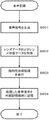
With reference to FIG. 4, an initial operation when the power of the camera body 102 is turned on will be described. When the power switch 183 of the camera body 102 is turned on, power is supplied to each part of the camera body 102. At the same time, the camera body 102 supplies power to each part of the interchangeable lens 301 through the body mount 140 and the lens mount 130.

次にコントローラ130は、レンズコントローラ320に対して交換レンズ301の認証情報を要求する。交換レンズ301の認証情報には、交換レンズの識別情報や、装着された交換レンズの種類に関する情報等が含まれる。レンズコントローラ320は、この要求に対して、交換レンズ301の認証情報をコントローラ130に送信することにより応答する。コントローラ130は、交換レンズ301の認証情報を取得することにより、カメラボディ102に装着された交換レンズ301の種類を把握する(S401)。   Next, the controller 130 requests authentication information of the interchangeable lens 301 from the lens controller 320. The authentication information of the interchangeable lens 301 includes identification information of the interchangeable lens, information related to the type of the interchangeable lens mounted, and the like. The lens controller 320 responds to this request by transmitting authentication information of the interchangeable lens 301 to the controller 130. The controller 130 grasps the type of the interchangeable lens 301 attached to the camera body 102 by acquiring authentication information of the interchangeable lens 301 (S401).

次にコントローラ130は、レンズコントローラ320に交換レンズ301の初期化を実行するように要求する。初期化動作には、フォーカスレンズ310およびズームレンズ312の位置のリセットや、絞り316の開閉状態のリセット等が含まれる。レンズコントローラ320はこの要求を受信すると、初期化動作を実行する。そしてレンズコントローラ320は初期化動作の完了後、初期化動作が完了したことを示す情報をコントローラ130に送信する。コントローラ130は、初期化動作が完了したことを示す情報を取得することにより、各レンズの初期化を把握する(S402)。   Next, the controller 130 requests the lens controller 320 to execute the initialization of the interchangeable lens 301. The initialization operation includes resetting the positions of the focus lens 310 and the zoom lens 312, resetting the open / close state of the aperture 316, and the like. When the lens controller 320 receives this request, it executes an initialization operation. Then, after the initialization operation is completed, the lens controller 320 transmits information indicating that the initialization operation is completed to the controller 130. The controller 130 grasps the initialization of each lens by acquiring information indicating that the initialization operation has been completed (S402).

次にコントローラ130は、レンズコントローラ320に対して、レンズデータを要求する。レンズデータとは、レンズの名称、レンズ広角端(ワイド端)の焦点距離とレンズ望遠端(テレ端)の焦点距離(ズーム制御可能範囲)、Fナンバー、フォーカス制御可能範囲、操作部材に関する情報など、交換レンズ301固有の特性値である。レンズデータは、交換レンズ301のフラッシュメモリ322に格納されている。レンズコントローラ320は、レンズデータの要求を受信すると、レンズデータをフラッシュメモリ322から読み出してコントローラ130に送信する。これにより、コントローラ130は交換レンズ301のレンズデータを取得する(S403)。   Next, the controller 130 requests lens data from the lens controller 320. Lens data refers to the name of the lens, the focal length of the lens wide-angle end (wide end) and the focal length of the lens telephoto end (tele end) (zoom controllable range), F-number, focus controllable range, information on the operation member, etc. These are characteristic values unique to the interchangeable lens 301. The lens data is stored in the flash memory 322 of the interchangeable lens 301. When receiving the lens data request, the lens controller 320 reads the lens data from the flash memory 322 and transmits it to the controller 130. Thereby, the controller 130 acquires the lens data of the interchangeable lens 301 (S403).

以上のように、カメラボディ102および交換レンズ301で必要となるデータが送受信されることにより、カメラボディ102および交換レンズ301の初期動作は完了する。   As described above, the initial operations of the camera body 102 and the interchangeable lens 301 are completed by transmitting and receiving data necessary for the camera body 102 and the interchangeable lens 301.

<2−2.動画撮影モードにおける動作>
本実施形態のデジタルカメラ100の動画撮影モード時の動作について説明する。デジタルカメラ100は、動画撮影モードにおける待機状態または動画撮影中である動画撮影状態において、スルー画像を表示部190に表示させる。以下では、まず動画撮影モード時の全体的な動作について説明し、次に動画撮影における音声記録の動作について説明する。
<2-2. Operation in movie shooting mode>
An operation in the moving image shooting mode of the digital camera 100 of the present embodiment will be described. The digital camera 100 causes the display unit 190 to display a through image in a standby state in the moving image shooting mode or in a moving image shooting state during moving image shooting. In the following, the overall operation in the moving image shooting mode will be described first, and then the sound recording operation in moving image shooting will be described.

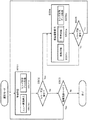
図5を参照して、動画撮影モードにおけるデジタルカメラ100の全体的な動作について説明する。カメラボディ102の電源スイッチ183が操作されて電源がON状態にされたときに、モードダイヤル184が動画撮影モードを示す状態に設定されていた場合、デジタルカメラ100は図4で示した初期動作を実行した後に動画撮影モードに移行する。   The overall operation of the digital camera 100 in the moving image shooting mode will be described with reference to FIG. When the power switch 183 of the camera body 102 is operated and the power is turned on, the digital camera 100 performs the initial operation shown in FIG. After execution, the mode shifts to the movie shooting mode.

デジタルカメラ100は、動画撮影モードに移行すると待機状態になる(S501)。待機状態においてコントローラ130は、デジタル画像・音声処理部120によって出力されたスルー画像を表示部190に表示させる(S501a)。また、待機状態においてコントローラ130は、レンズコントローラ320に対して、交換レンズ301の状態を示すレンズ状態データを要求する。レンズ状態データは、例えば、ズームレンズ312による現在の焦点距離情報、フォーカスレンズ310の現在の位置情報、絞り316の現在の絞り値情報および操作リング315が操作されたことを示す操作リング操作情報などを含む。レンズコントローラ320はこの要求を受信すると、コントローラ130に対してレンズ状態データを送信する(S501b)。   When the digital camera 100 shifts to the moving image shooting mode, the digital camera 100 enters a standby state (S501). In the standby state, the controller 130 causes the display unit 190 to display the through image output by the digital image / sound processing unit 120 (S501a). In the standby state, the controller 130 requests lens state data indicating the state of the interchangeable lens 301 from the lens controller 320. The lens state data includes, for example, current focal length information by the zoom lens 312, current position information of the focus lens 310, current aperture value information of the aperture 316, and operation ring operation information indicating that the operation ring 315 has been operated. including. Upon receiving this request, the lens controller 320 transmits lens state data to the controller 130 (S501b).

待機状態においてコントローラ130は、レリーズ釦181が押下されたか否かを判定する。   In the standby state, the controller 130 determines whether or not the release button 181 has been pressed.

コントローラ130は、レリーズ釦181が押下されたと判定すると(ステップS502におけるYes)、動画撮影動作に移行する(S504)。動画撮影動作は、画像記録動作(S504v)と、音声記録動作(S504a)と、レンズ状態データ取得動作(S504d)とを含む。動画撮影動作においては、例えば1フレーム期間単位で画像情報および音声信号の記録動作が実行される。1フレーム期間の長さは、動画撮影時のフレームレートの逆数となる。例えばフレームレートが60フレーム/秒であれば、1フレーム期間は1/60秒となる。レンズ状態データ取得動作(S504d)として、コントローラ130はレンズコントローラ320に対してレンズ状態データを要求する。レンズコントローラ320はこの要求に応答してコントローラ130にレンズ状態データを送信する。コントローラ130は、レンズ状態データを受信し、必要に応じて受信されたレンズ状態データをROM170に格納する。画像記録動作(S504v)は、デジタルカメラ100の構成の説明時に概略を示したので、ここでの説明は省略する。音声記録動作(S504a)の詳細については後述する。   If the controller 130 determines that the release button 181 has been pressed (Yes in step S502), the controller 130 proceeds to a moving image shooting operation (S504). The moving image shooting operation includes an image recording operation (S504v), an audio recording operation (S504a), and a lens state data acquisition operation (S504d). In the moving image shooting operation, for example, image information and audio signal recording operations are executed in units of one frame period. The length of one frame period is the reciprocal of the frame rate at the time of moving image shooting. For example, if the frame rate is 60 frames / second, one frame period is 1/60 seconds. As the lens state data acquisition operation (S504d), the controller 130 requests lens state data from the lens controller 320. The lens controller 320 transmits lens state data to the controller 130 in response to this request. The controller 130 receives the lens state data, and stores the received lens state data in the ROM 170 as necessary. Since the image recording operation (S504v) is outlined when the configuration of the digital camera 100 is described, the description thereof is omitted here. Details of the voice recording operation (S504a) will be described later.

コントローラ130は、1フレーム期間の動画撮影動作を終了すると、レリーズ釦181が再び押下されたか否かを判定する。コントローラ130は、レリーズ釦181が押下されていないと判定すると(ステップS505のNo)、再び動画撮影動作を実行する。一方、コントローラ130は、レリーズ釦181が押下されたと判定すると(ステップS505のYes)、待機状態に移行する(S501)。このように、動画撮影モードのデジタルカメラ100は、レリーズ釦181が押下されてから、再びレリーズ釦181が押下されるまでの期間、動画撮影動作を実行する。   When the moving image shooting operation for one frame period is completed, the controller 130 determines whether or not the release button 181 is pressed again. If the controller 130 determines that the release button 181 has not been pressed (No in step S505), the controller 130 executes the moving image shooting operation again. On the other hand, when determining that the release button 181 has been pressed (Yes in step S505), the controller 130 shifts to a standby state (S501). As described above, the digital camera 100 in the moving image shooting mode performs the moving image shooting operation during the period from when the release button 181 is pressed until the release button 181 is pressed again.

一方、待機状態においてコントローラ130がレリーズ釦181は押下されていないと判定した場合(ステップS502におけるNo)、使用者によって設定された動作モードが動画撮影モードか否かを判定する(S503)。コントローラ130は、設定された動作モードが動画撮影モードであると判定すると(ステップS503におけるYes)、待機状態に移行する(S501)。一方、コントローラ130は、設定された動作モードが動画撮影モードでないと判定すると(ステップS503におけるNo)、動画撮影モードを終了する。   On the other hand, when the controller 130 determines that the release button 181 has not been pressed in the standby state (No in step S502), it is determined whether or not the operation mode set by the user is the moving image shooting mode (S503). If the controller 130 determines that the set operation mode is the moving image shooting mode (Yes in step S503), the controller 130 shifts to a standby state (S501). On the other hand, when determining that the set operation mode is not the moving image shooting mode (No in step S503), the controller 130 ends the moving image shooting mode.

<2−3.音声記録動作>
デジタルカメラ100は音響ズーム機能を有している。音響ズーム機能を実現するための動作は、音声記録動作において実行される。
<2-3. Voice recording operation>
The digital camera 100 has an acoustic zoom function. The operation for realizing the acoustic zoom function is executed in the sound recording operation.

以下、デジタルカメラ100の音響ズーム機能について説明する。「音響ズーム機能」とは、交換レンズ301のズーム倍率に連動して、音声入力系110の収音特性を変更する機能である。音響ズーム機能は、入力した音声信号に対するデジタル画像・音声処理部120による指向性合成処理により実現される。音響ズーム機能により、交換レンズのズーム倍率(光学的な画角)の変動に従って、使用者は音声再生時に聴感上のステレオ感およびズーム感を得ることができる。ここで、「ステレオ感」は、使用者の周辺で音が鳴っているかのように感じられることである。「ズーム感」は、遠くの音が使用者の近傍で鳴っているかのように感じられることである。   Hereinafter, the acoustic zoom function of the digital camera 100 will be described. The “acoustic zoom function” is a function that changes the sound collection characteristics of the audio input system 110 in conjunction with the zoom magnification of the interchangeable lens 301. The acoustic zoom function is realized by directivity synthesis processing by the digital image / audio processing unit 120 with respect to the input audio signal. With the acoustic zoom function, the user can obtain a sense of stereo and a sense of zoom when listening to sound according to the change in the zoom magnification (optical angle of view) of the interchangeable lens. Here, the “stereo feeling” means that the user feels as if sound is being generated around the user. “Zoom feeling” means that it feels as if a distant sound is being played in the vicinity of the user.

指向性合成処理において、指向特性は、最も狭い範囲での収音を可能とするための、すなわち、最大のズーム感を与えるようにするための指向特性(このときの指向特性の限界を「音響テレ端」という)から、最も広い範囲での収音を可能とするための、すなわち、最大のステレオ感を与えるようにするための指向特性(このときの指向特性の限界を「音響ワイド端」という)まで変更されることが可能である。   In the directivity synthesis processing, the directivity is the directivity for enabling sound collection in the narrowest range, that is, for providing the maximum zoom feeling. Directivity to enable sound collection in the widest range from the “tele end”, that is, to give the maximum stereo feeling (the limit of directivity at this time is the “acoustic wide end” Can be changed.

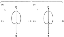
図6および図7は音響ズーム機能において設定される指向性合成処理における指向特性を説明した図である。図6は、最も広い範囲での収音を可能とする音響ワイド端での指向特性を示し、図7は、最も狭い範囲での収音を可能とする音響テレ端での指向特性を示す。   6 and 7 are diagrams for explaining the directivity characteristics in the directivity synthesis processing set in the acoustic zoom function. FIG. 6 shows the directivity characteristic at the acoustic wide end that enables sound collection in the widest range, and FIG. 7 shows the directivity characteristic at the acoustic telephoto end that enables sound collection in the narrowest range.

図6(a)および図7(a)は、左マイクロホン111Lの入力に関する指向特性を示し、図6(b)および図7(b)は、右マイクロホン111Rの入力に関する指向特性を示す。音響ズーム(指向特性)が音響ワイド端に設定されている場合、図6に示すように、音声信号に最大のステレオ感が付与されるため、左右方向の指向特性が大きくされる。一方、音響ズームが音響テレ端に設定されている場合、図7に示すように、音声信号に最大のズーム感が付与されるため、左右方向の指向特性が小さくされ、かつ前方向の指向特性が大きくされる。また、音声信号に最大のズーム感が付与されるために、他には、音声信号の高域および低域が小さくされ、中域が大きくされ、かつ音量が大きくされる。なお、音響ズームに関する技術は公知の種々の技術がある(例えば、日本国特許第4138290号参照)。本実施形態では音響ズームの程度(指向特性)を、音響ズームワイド端と音響ズームテレ端の間で線形に変更することができる。   FIGS. 6A and 7A show directional characteristics related to the input of the left microphone 111L, and FIGS. 6B and 7B show directional characteristics related to the input of the right microphone 111R. When the acoustic zoom (directional characteristic) is set to the acoustic wide end, as shown in FIG. 6, since the maximum stereo feeling is given to the audio signal, the horizontal directional characteristic is increased. On the other hand, when the acoustic zoom is set at the acoustic telephoto end, as shown in FIG. 7, since the maximum zoom feeling is given to the audio signal, the horizontal directivity is reduced and the forward directivity is also provided. Is increased. In addition, since the maximum zoom feeling is imparted to the audio signal, the high frequency and low frequency of the audio signal are reduced, the mid range is increased, and the volume is increased. There are various known techniques relating to acoustic zoom (see, for example, Japanese Patent No. 4138290). In this embodiment, the degree (directivity) of the acoustic zoom can be changed linearly between the acoustic zoom wide end and the acoustic zoom tele end.

図8を参照して、図4で示した音声記録動作(S504a)について説明する。アナログ音声処理部115は、マイクロホン部111によって入力された音声信号に各種のアナログ信号処理を施した後、処理を施した音声信号をデジタル画像・音声処理部120に出力する(S601)。   With reference to FIG. 8, the voice recording operation (S504a) shown in FIG. 4 will be described. The analog audio processing unit 115 performs various analog signal processing on the audio signal input by the microphone unit 111, and then outputs the processed audio signal to the digital image / audio processing unit 120 (S601).

次にコントローラ130は、レンズデータおよびレンズ状態データをROM170から読み出す(S602)。レンズデータには、交換レンズ301に固有のレンズワイド端の焦点距離の情報と、レンズテレ端の焦点距離の情報とが含まれる。レンズ状態データには、現在の焦点距離情報および/またはズーム倍率情報が含まれる。コントローラ130はこれらの情報をデジタル画像・音声処理部120に入力する。   Next, the controller 130 reads lens data and lens state data from the ROM 170 (S602). The lens data includes information on the focal length at the lens wide end unique to the interchangeable lens 301 and information on the focal length at the lens telephoto end. The lens state data includes current focal length information and / or zoom magnification information. The controller 130 inputs such information to the digital image / sound processor 120.

デジタル画像・音声処理部120は、入力されたレンズデータおよびレンズ状態データに基づいて、音声信号に対して指向性合成処理を施す(S603)。指向性合成処理とは、デジタル画像・音声処理部120が、入力された音声信号を合成して音声信号の指向特性を調節することである。音声信号の指向特性が調節されることにより、音響ズーム機能が実現される。指向特性の調整についての詳細は後述する。   The digital image / sound processing unit 120 performs directivity synthesis processing on the sound signal based on the input lens data and lens state data (S603). The directivity synthesis processing is that the digital image / audio processing unit 120 synthesizes the input audio signal to adjust the directivity characteristics of the audio signal. The acoustic zoom function is realized by adjusting the directivity characteristics of the audio signal. Details of the directivity adjustment will be described later.

デジタル画像・音声処理部120によって指向性合成処理が施された音声信号は、外部記憶媒体160に記録される(S604)。   The audio signal subjected to the directivity synthesis process by the digital image / audio processing unit 120 is recorded in the external storage medium 160 (S604).

以下、音声信号に施される指向性合成処理について説明する。交換レンズ301の現在の焦点距離がレンズワイド端に位置した場合、デジタル画像・音声処理部120は、音響ズーム効果(指向性合成処理の結果)が音響ワイド端での効果が得られるように、指向性合成処理を実行する。具体的には、デジタル画像・音声処理部120は、指向性合成処理における指向特性を図6(a)、(b)で示すような特性に設定する。一方、交換レンズ301の現在の焦点距離がレンズテレ端に位置した場合、デジタル画像・音声処理部120は、音響ズーム効果が音響テレ端での効果が得られるように、指向性合成処理を実行する。具体的には、デジタル画像・音声処理部120は、指向性合成処理における指向特性を図7(a)、(b)で示すような特性に設定する。そして、交換レンズ301の現在の焦点距離がレンズワイド端とレンズテレ端との間に位置した場合は、現在の焦点距離に比例して、音響ズームの度合いが調節される。つまり、音響ワイド端と音響テレ端との間における音響ズームの度合いが、レンズワイド端とレンズテレ端との間における交換レンズ301の焦点距離の位置に対応するように、デジタル画像・音声処理部120は指向性合成処理を施す。以下、交換レンズ301の焦点距離と音響ズームの関係について説明する。   Hereinafter, directivity synthesis processing performed on the audio signal will be described. When the current focal length of the interchangeable lens 301 is located at the lens wide end, the digital image / sound processing unit 120 is configured so that the acoustic zoom effect (result of directivity synthesis processing) is effective at the acoustic wide end. Execute directivity synthesis processing. Specifically, the digital image / sound processing unit 120 sets the directivity characteristics in the directivity synthesis processing to characteristics as shown in FIGS. 6 (a) and 6 (b). On the other hand, when the current focal length of the interchangeable lens 301 is positioned at the lens telephoto end, the digital image / sound processing unit 120 executes directivity synthesis processing so that the acoustic zoom effect is obtained at the acoustic telephoto end. . Specifically, the digital image / sound processing unit 120 sets the directivity characteristics in the directivity synthesis processing to characteristics as shown in FIGS. When the current focal length of the interchangeable lens 301 is located between the lens wide end and the lens telephoto end, the degree of acoustic zoom is adjusted in proportion to the current focal length. That is, the digital image / sound processing unit 120 is configured so that the degree of acoustic zoom between the acoustic wide end and the acoustic tele end corresponds to the position of the focal length of the interchangeable lens 301 between the lens wide end and the lens tele end. Performs directivity synthesis processing. Hereinafter, the relationship between the focal length of the interchangeable lens 301 and the acoustic zoom will be described.

図9のグラフを参照して、交換レンズ301の焦点距離と、音声信号に付与される音響ズーム効果との関係について説明する。横軸は交換レンズ301の現在の焦点距離(光学ズーム)を示す。左に行くほど撮像範囲(画角)が広くなり(レンズワイド側)、右に行くほど撮像範囲が狭くなる(レンズテレ側)。縦軸は音響ズーム効果の度合い(指向性合成処理の結果)を示す。下に行くほど聴感上のステレオ感が大きくなり(音響ワイド端側)、上に行くほど聴感上のズーム感が大きくなる(音響テレ端側)。図9(a)は、焦点距離の設定可能な範囲が14mm(レンズワイド端)−45mm(レンズテレ端)の交換レンズ301に対して設定される音響ズーム効果を説明するための図である。図9(b)は、交換レンズ301の焦点距離の設定可能な範囲が45mm(レンズワイド端)−200mm(レンズテレ端)の交換レンズ301に対して設定される音響ズーム効果を説明するための図である。   The relationship between the focal length of the interchangeable lens 301 and the acoustic zoom effect imparted to the audio signal will be described with reference to the graph of FIG. The horizontal axis indicates the current focal length (optical zoom) of the interchangeable lens 301. The imaging range (view angle) becomes wider toward the left (lens wide side), and the imaging range becomes narrower toward the right (lens telephoto side). The vertical axis indicates the degree of the acoustic zoom effect (result of directivity synthesis processing). As you go down, the sense of stereo feeling increases (acoustic wide end side), and as you go up, the sense of zoom feel increases (acoustic tele end side). FIG. 9A is a diagram for explaining the acoustic zoom effect set for the interchangeable lens 301 having a focal length setting range of 14 mm (lens wide end) -45 mm (lens telephoto end). FIG. 9B is a diagram for explaining the acoustic zoom effect that is set for the interchangeable lens 301 having a settable focal length of the interchangeable lens 301 of 45 mm (lens wide end) -200 mm (lens telephoto end). It is.

図9(a)の場合、交換レンズ301の最小の焦点距離14mm(レンズワイド端)が音響ズームの音響ワイド端(W端)に対応付けられ、交換レンズ301の最大の焦点距離45mm(レンズテレ端)が音響ズームの音響テレ端(T端)に対応付けられる。一方、図9(b)の場合、交換レンズ301の最小の焦点距離45mm(レンズワイド端)が音響ズームの音響ワイド端(W端)に対応付けられ、交換レンズ301の最大の焦点距離200mm(レンズテレ端)が音響ズームの音響テレ端(T端)に対応付けられる。   In the case of FIG. 9A, the minimum focal length 14 mm (lens wide end) of the interchangeable lens 301 is associated with the acoustic wide end (W end) of the acoustic zoom, and the maximum focal length 45 mm (lens telephoto end) of the interchangeable lens 301 is obtained. ) Is associated with the acoustic telephoto end (T end) of the acoustic zoom. On the other hand, in the case of FIG. 9B, the minimum focal length 45 mm (lens wide end) of the interchangeable lens 301 is associated with the acoustic wide end (W end) of the acoustic zoom, and the maximum focal length 200 mm ( The lens telephoto end) is associated with the acoustic telephoto end (T end) of the acoustic zoom.

このように、交換レンズ301の種類に依存せず、交換レンズ301の有する最大の焦点距離に音響ズームの音響テレ端が対応付けられ、最小の焦点距離に音響ズームの音響ワイド端が対応付けられる。つまり、図9(a)および(b)を見ても分かるように、交換レンズ301の設定された焦点距離が同じ45mmであっても、その焦点距離が交換レンズ301にとってレンズワイド端に相当するのかレンズテレ端に相当するのかによって、音声信号に付与される音響ズームの度合いが異なる。   Thus, regardless of the type of the interchangeable lens 301, the acoustic telephoto end of the acoustic zoom is associated with the maximum focal length of the interchangeable lens 301, and the acoustic wide end of the acoustic zoom is associated with the minimum focal length. . That is, as can be seen from FIGS. 9A and 9B, even if the set focal length of the interchangeable lens 301 is the same 45 mm, the focal length corresponds to the lens wide end for the interchangeable lens 301. The degree of acoustic zoom applied to the audio signal differs depending on whether it corresponds to the lens telephoto end.

図9(a)および(b)のそれぞれの場合において、交換レンズ301の焦点距離がレンズワイド端とレンズテレ端との間に設定されたときは、レンズワイド端およびレンズテレ端に対する焦点距離の相対的な位置に従って、音響ワイド端および音響テレ端に対する、音響ズームの相対的な度合いが決定される。   9A and 9B, when the focal length of the interchangeable lens 301 is set between the lens wide end and the lens telephoto end, the relative focal length with respect to the lens wide end and the lens telephoto end is set. The relative degree of acoustic zoom relative to the acoustic wide end and the acoustic tele end is determined according to the position.

本実施形態のデジタルカメラ100において、音響ズームは音響ワイド端と音響テレ端とが線形補完されて実現される。しかし、線形補完以外の補完方法で音響ズームが実現されてもよい。   In the digital camera 100 of the present embodiment, the acoustic zoom is realized by linearly complementing the acoustic wide end and the acoustic tele end. However, the acoustic zoom may be realized by a complementing method other than linear interpolation.

以上のように、交換レンズ301の光学ズームの両端を音響ズームの両端に対応させることにより、交換レンズ301の設定可能な焦点距離の範囲が変わっても、音響ズームを最大限に利用することが可能となる。これにより、レンズの種類に関わらず、使用者に音響ズームをより確実に体感させることが可能である。   As described above, by making both ends of the optical zoom of the interchangeable lens 301 correspond to both ends of the acoustic zoom, even if the range of the focal length that can be set for the interchangeable lens 301 changes, the acoustic zoom can be used to the maximum extent. It becomes possible. As a result, regardless of the type of lens, it is possible for the user to experience acoustic zoom more reliably.

<3.本実施形態のまとめ>
本実施形態のカメラボディ102は、ズーム倍率が可変の交換レンズ301を装着可能なカメラボディである。カメラボディ102は、交換レンズ301が取りうるズーム倍率の範囲を示す情報であるレンズデータを、交換レンズ301から受信するコントローラ130と、音声を収音して音声データを生成するマイクロホン部111と、交換レンズ301のズーム倍率と連動して、マイクロホン部111の指向特性に関する設定を変更するデジタル画像・音声処理部120とを備える。レンズデータは交換レンズ301がとり得る最大倍率および最小倍率に対応する情報を含む。マイクロホン部111の指向特性は、最も幅の広い領域の音声の収音を可能とする音響ワイド端から、最も幅の狭い領域の音声の収音を可能とする音響テレ端の間で変更可能である。デジタル画像・音声処理部120は、レンズデータに基づいて、交換レンズ301がズームの最小倍率を与える位置にあるときはマイクロホン部111の指向特性を音響ワイド端に設定し、交換レンズ301がズームの最大倍率を与える位置にあるときはマイクロホン部111の指向特性を音響テレ端に設定する。
<3. Summary of this embodiment>
The camera body 102 of the present embodiment is a camera body to which an interchangeable lens 301 with a variable zoom magnification can be attached. The camera body 102 includes a controller 130 that receives lens data, which is information indicating the range of zoom magnification that the interchangeable lens 301 can take, from the interchangeable lens 301, a microphone unit 111 that collects sound and generates sound data, A digital image / sound processing unit 120 that changes settings relating to directivity characteristics of the microphone unit 111 in conjunction with the zoom magnification of the interchangeable lens 301 is provided. The lens data includes information corresponding to the maximum magnification and the minimum magnification that the interchangeable lens 301 can take. The directivity characteristics of the microphone unit 111 can be changed between the acoustic wide end that can collect the sound in the widest region and the acoustic tele end that can collect the sound in the narrowest region. is there. Based on the lens data, the digital image / sound processing unit 120 sets the directivity characteristic of the microphone unit 111 to the acoustic wide end when the interchangeable lens 301 is at a position that gives the minimum zoom magnification, and the interchangeable lens 301 is zoomed. When the maximum magnification is provided, the directivity characteristic of the microphone unit 111 is set to the acoustic tele end.

また、本実施形態の交換レンズ301は、カメラボディ102に装着可能な交換レンズである。交換レンズ301は、レンズデータを記憶しているフラッシュメモリ322と、レンズデータをカメラボディ102に送信するレンズコントローラ320とを備える。   Further, the interchangeable lens 301 of the present embodiment is an interchangeable lens that can be attached to the camera body 102. The interchangeable lens 301 includes a flash memory 322 that stores lens data, and a lens controller 320 that transmits the lens data to the camera body 102.

このような構成を有するカメラボディ102および交換レンズ301によれば、ズームレンズの設定可能な焦点距離の範囲に関わらず、使用者に音響ズームをより確実に体感させることが可能である。   According to the camera body 102 and the interchangeable lens 301 having such a configuration, it is possible to make the user experience acoustic zoom more reliably regardless of the range of the focal length that can be set for the zoom lens.

<4.他の実施形態>
本発明は、前述の実施形態に限定されず、種々の実施形態が考えられる。以下、本発明の他の実施形態についてまとめて記述する。
<4. Other embodiments>
The present invention is not limited to the above-described embodiment, and various embodiments are conceivable. Hereinafter, other embodiments of the present invention will be described together.

前述の実施形態において、コントローラ130は交換レンズ301から、絶対値としての焦点距離に関する情報を取得するとした。しかし、焦点距離に関する情報として相対的な値を取得してもよい。例えば、レンズデータとして交換レンズ301の広角端に対する望遠端のズーム倍率に関する情報を取得し、レンズ状態データとして交換レンズ301の広角端に対する現在のズーム倍率を取得してもよい。   In the above-described embodiment, the controller 130 acquires information on the focal length as an absolute value from the interchangeable lens 301. However, you may acquire a relative value as information regarding a focal distance. For example, information regarding the zoom magnification at the telephoto end with respect to the wide angle end of the interchangeable lens 301 may be acquired as lens data, and the current zoom magnification with respect to the wide angle end of the interchangeable lens 301 may be acquired as lens state data.

また、前述の実施形態のカメラが2つのマイクロホンを備えるとした。しかし本発明はこれに限定されない。カメラが3つ以上のマイクロホンを備えてもよい。ただし、音声信号の指向性を調節できるように複数のマイクロホンは適宜配置され、信号は処理される。   In addition, the camera of the above-described embodiment includes two microphones. However, the present invention is not limited to this. The camera may include three or more microphones. However, the plurality of microphones are appropriately arranged so that the directivity of the audio signal can be adjusted, and the signal is processed.

また、前述の実施形態において、カメラとしてデジタルカメラ100を例に挙げて説明した。しかしながら、レンズ交換可能であり、動画撮影が可能な機器であればよい。例えば、ビデオカメラに対しても本発明を適用できる。   In the above-described embodiment, the digital camera 100 has been described as an example of the camera. However, any device can be used as long as it can exchange lenses and can shoot moving images. For example, the present invention can be applied to a video camera.

また、前述の実施形態において、デジタル画像・音声処理部120およびコントローラ130は個別の部材として、機能および構成を説明した。しかしデジタル画像・音声処理部120およびコントローラ130の一方の構成および/または機能が、他方に含まれてもよい。   In the above-described embodiment, the digital image / sound processing unit 120 and the controller 130 have been described as functions and configurations as separate members. However, one configuration and / or function of the digital image / sound processor 120 and the controller 130 may be included in the other.

また、前述の実施形態において、撮像素子としてCCDイメージセンサ143を例示した。しかし撮像素子はこれに限定されない。CMOSイメージセンサやNMOSイメージセンサ等を、撮像素子として使用してもよい。   In the above-described embodiment, the CCD image sensor 143 is exemplified as the image sensor. However, the imaging device is not limited to this. A CMOS image sensor, an NMOS image sensor, or the like may be used as the image sensor.

また、前述の実施形態において、フォーカスレンズ、ズームレンズおよび絞りを備えた交換レンズを例示した。しかし本発明はこれに限定されない。少なくともズームレンズを備えた交換レンズが装着されたカメラボディであれば、前述の実施形態の思想を適用できる。   Further, in the above-described embodiment, the interchangeable lens including the focus lens, the zoom lens, and the diaphragm is illustrated. However, the present invention is not limited to this. The idea of the above-described embodiment can be applied to any camera body on which an interchangeable lens having at least a zoom lens is mounted.

本発明は、音声記録機能を有する撮像装置(デジタルカメラやムービーカメラなど)に対して適用できる。   The present invention can be applied to an imaging device (such as a digital camera or a movie camera) having an audio recording function.

100 デジタルカメラ
102 カメラボディ
110 音声入力系
111 マイクロホン部
111L 左マイクロホン
111R 右マイクロホン
115 アナログ音声処理部
120 デジタル画像・音声処理部
130 コントローラ
140 画像入力系
143 CCDイメージセンサ
150 RAM
160 外部記憶媒体
170 ROM
180 操作部
181 レリーズ釦
183 電源スイッチ
184 モードダイヤル
185 中央釦
186 十字釦
190 表示部
195 スピーカー
301 交換レンズ
310 フォーカスレンズ
311 フォーカスレンズ駆動部
312 ズームレンズ
313 ズームレンズ駆動部
315 操作リング
316 絞り
317 絞り駆動部
320 レンズコントローラ
321 DRAM
322 フラッシュメモリ
330 レンズマウント
340 ボディマウント
DESCRIPTION OF SYMBOLS 100 Digital camera 102 Camera body 110 Sound input system 111 Microphone part 111L Left microphone 111R Right microphone 115 Analog sound processing part 120 Digital image and sound processing part 130 Controller 140 Image input system 143 CCD image sensor 150 RAM
160 External storage medium 170 ROM
180 Operation unit 181 Release button 183 Power switch 184 Mode dial 185 Center button 186 Cross button 190 Display unit 195 Speaker 301 Interchangeable lens 310 Focus lens 311 Focus lens drive unit 312 Zoom lens 313 Zoom lens drive unit 315 Operation ring 316 Diaphragm 317 Part 320 lens controller 321 DRAM
322 Flash memory 330 Lens mount 340 Body mount

Claims (4)

ズーム倍率が可変の交換レンズを装着可能なカメラ本体であって、
前記交換レンズが取りうるズーム倍率の範囲を示す情報であるズーム範囲情報を、前記交換レンズから受信する受信部と、
音声を収音して音声データを生成する収音部と、
前記交換レンズのズーム倍率と連動して、前記収音部の指向特性に関する設定を変更する音声処理部と
を備え、
前記ズーム範囲情報は前記交換レンズがとり得る最大倍率および最小倍率に対応する情報を含み、
前記収音部の指向特性は、最も幅の広い領域の音声の収音を可能とする第1の指向特性から、最も幅の狭い領域の音声の収音を可能とする第2の指向特性の間で変更可能であり、
前記音声処理部は、前記ズーム範囲情報に基づいて、前記交換レンズがズームの最小倍率を与える位置にあるときは前記収音部の指向特性を前記第1の指向特性に設定し、前記交換レンズがズームの最大倍率を与える位置にあるときは前記収音部の指向特性を前記第2の指向特性に設定する
ことを特徴とする
カメラ本体。
A camera body that can be fitted with an interchangeable lens with variable zoom magnification.
A receiving unit that receives from the interchangeable lens zoom range information that is information indicating a range of zoom magnification that the interchangeable lens can take;
A sound collection unit for collecting sound and generating sound data;
In conjunction with the zoom magnification of the interchangeable lens, an audio processing unit that changes settings related to directivity characteristics of the sound collection unit,
The zoom range information includes information corresponding to the maximum magnification and the minimum magnification that the interchangeable lens can take,
The directivity characteristic of the sound collection unit is that of the second directivity characteristic that enables sound collection of the narrowest area from the first directivity characteristic that allows sound collection of the widest area. Can be changed between
The sound processing unit sets a directivity characteristic of the sound pickup unit to the first directivity characteristic when the interchangeable lens is at a position that gives a minimum zoom magnification based on the zoom range information, and the interchangeable lens A camera main body characterized by setting the directivity characteristic of the sound pickup unit to the second directivity characteristic when is at a position that gives the maximum zoom magnification.
前記ズーム範囲情報は、前記交換レンズの画角を示す情報であることを特徴とする
請求項1記載のカメラ本体。
The camera body according to claim 1, wherein the zoom range information is information indicating an angle of view of the interchangeable lens.
前記ズーム範囲情報は、前記交換レンズがとり得る最大のズーム倍率を示す情報であることを特徴とする
請求項1記載のカメラ本体。
The camera body according to claim 1, wherein the zoom range information is information indicating a maximum zoom magnification that the interchangeable lens can take.
請求項1ないし3いずれか記載のカメラ本体に装着可能な交換レンズであって、
前記ズーム範囲情報を記憶している記憶部と、
前記ズーム範囲情報を前記カメラ本体に送信する送信部と
を備える、
交換レンズ。
An interchangeable lens that can be attached to the camera body according to any one of claims 1 to 3,
A storage unit storing the zoom range information;
A transmission unit that transmits the zoom range information to the camera body.
interchangeable lens.
JP2012123252A 2011-06-06 2012-05-30 Camera and interchangeable lens mountable on camera Pending JP2013017160A (en)

Priority Applications (1)

Application Number Priority Date Filing Date Title
JP2012123252A JP2013017160A (en) 2011-06-06 2012-05-30 Camera and interchangeable lens mountable on camera

Applications Claiming Priority (3)

Application Number Priority Date Filing Date Title
JP2011125979 2011-06-06
JP2012123252A JP2013017160A (en) 2011-06-06 2012-05-30 Camera and interchangeable lens mountable on camera

Publications (2)

Publication Number Publication Date
JP2013017160A true JP2013017160A (en) 2013-01-24
JP2013017160A5 JP2013017160A5 (en) 2015-03-12

Family

ID=47261769

Family Applications (1)

Application Number Title Priority Date Filing Date
JP2012123252A Pending JP2013017160A (en) 2011-06-06 2012-05-30 Camera and interchangeable lens mountable on camera

Country Status (2)

Country Link
US (1) US8712231B2 (en)
JP (1) JP2013017160A (en)

Cited By (2)

* Cited by examiner, † Cited by third party
Publication number Priority date Publication date Assignee Title
WO2015068492A1 (en) * 2013-11-08 2015-05-14 富士フイルム株式会社 Camera system, camera body, interchangeable lens, and communication method
JP2016039410A (en) * 2014-08-05 2016-03-22 キヤノン株式会社 Signal processing apparatus and signal processing method

Families Citing this family (4)

* Cited by examiner, † Cited by third party
Publication number Priority date Publication date Assignee Title
US10555062B2 (en) * 2016-08-31 2020-02-04 Panasonic Intellectual Property Management Co., Ltd. Sound pick up device with sound blocking shields and imaging device including the same
US11089199B2 (en) * 2018-06-21 2021-08-10 Canon Kabushiki Kaisha Accessory device, imaging apparatus, and methods for controlling the same
US11838652B2 (en) * 2021-07-15 2023-12-05 Samsung Electronics Co., Ltd. Method for storing image and electronic device supporting the same
CN114363512B (en) * 2021-09-30 2023-10-24 北京荣耀终端有限公司 Video processing method and related electronic equipment

Citations (3)

* Cited by examiner, † Cited by third party
Publication number Priority date Publication date Assignee Title
JP2010256739A (en) * 2009-04-28 2010-11-11 Canon Inc Imaging apparatus
JP2012010134A (en) * 2010-06-25 2012-01-12 Nikon Corp Image recording device
JP2012204900A (en) * 2011-03-24 2012-10-22 Olympus Imaging Corp Recording device

Family Cites Families (11)

* Cited by examiner, † Cited by third party
Publication number Priority date Publication date Assignee Title
JPS62149295A (en) 1985-12-23 1987-07-03 Canon Inc Sound recordable camera
JPH08182091A (en) 1994-12-21 1996-07-12 Hitachi Ltd Camcorder
JPH11341592A (en) 1998-05-28 1999-12-10 Mitsubishi Electric Corp Sound recorder to be synchronized with image pickup device
JP2000059667A (en) * 1998-08-07 2000-02-25 Olympus Optical Co Ltd Electronic camera and silver salt camera
EP1202602B1 (en) 2000-10-25 2013-05-15 Panasonic Corporation Zoom microphone device
CN102016679B (en) * 2008-03-28 2013-07-03 松下电器产业株式会社 Camera system
US8319858B2 (en) * 2008-10-31 2012-11-27 Fortemedia, Inc. Electronic apparatus and method for receiving sounds with auxiliary information from camera system
JP5361398B2 (en) 2009-01-05 2013-12-04 キヤノン株式会社 Imaging device
JP2010200253A (en) 2009-02-27 2010-09-09 Nikon Corp Imaging apparatus
JP2010226412A (en) 2009-03-24 2010-10-07 Panasonic Corp Imaging apparatus
JP5391008B2 (en) * 2009-09-16 2014-01-15 キヤノン株式会社 Imaging apparatus and control method thereof

Patent Citations (3)

* Cited by examiner, † Cited by third party
Publication number Priority date Publication date Assignee Title
JP2010256739A (en) * 2009-04-28 2010-11-11 Canon Inc Imaging apparatus
JP2012010134A (en) * 2010-06-25 2012-01-12 Nikon Corp Image recording device
JP2012204900A (en) * 2011-03-24 2012-10-22 Olympus Imaging Corp Recording device

Cited By (3)

* Cited by examiner, † Cited by third party
Publication number Priority date Publication date Assignee Title
WO2015068492A1 (en) * 2013-11-08 2015-05-14 富士フイルム株式会社 Camera system, camera body, interchangeable lens, and communication method
US9699363B2 (en) 2013-11-08 2017-07-04 Fujifilm Corporation Camera system, camera body, interchangeable lens, and communication method
JP2016039410A (en) * 2014-08-05 2016-03-22 キヤノン株式会社 Signal processing apparatus and signal processing method

Also Published As

Publication number Publication date
US20120308220A1 (en) 2012-12-06
US8712231B2 (en) 2014-04-29

Similar Documents

Publication Publication Date Title
US20230353869A1 (en) Imaging apparatus and setting screen thereof
US8767976B2 (en) Sound pickup device
JP2013017160A (en) Camera and interchangeable lens mountable on camera
JP2012118522A (en) Camera body, interchangeable lens, and intermediate lens
JPWO2012002307A1 (en) Monocular stereoscopic imaging device
JP2011019245A (en) Image processing apparatus and photographing apparatus
JP2006287735A (en) Picture voice recording apparatus and collecting voice direction adjustment method
JP2005228400A (en) Sound recording device and method
JP6617285B2 (en) Imaging device
US9064487B2 (en) Imaging device superimposing wideband noise on output sound signal
US10104291B2 (en) Imaging device
JP2010200253A (en) Imaging apparatus
US9648220B2 (en) Imaging apparatus, imaging apparatus body and image sound output method
WO2012035675A1 (en) Audio recording device
JP2007248698A (en) Method and apparatus for imaging
JP2011188055A (en) Imaging device
JP2005202037A (en) Stereo camera
JP2012010134A (en) Image recording device
JP7379046B2 (en) Imaging device, method of controlling the imaging device, and its program
JP2010204303A (en) Imaging apparatus
KR20130092213A (en) Digital photographing apparatus and control method thereof
JP2017195558A (en) Imaging apparatus
JP2011150047A (en) Camera body, interchangeable lens, and camera system
JP2023072581A (en) Imaging apparatus and method for controlling the same, lens device, data for image magnification correction, image processing apparatus and image processing method, and accessory device
JP4818493B1 (en) Audio recording device

Legal Events

Date Code Title Description
A711 Notification of change in applicant

Free format text: JAPANESE INTERMEDIATE CODE: A711

Effective date: 20141003

RD03 Notification of appointment of power of attorney

Free format text: JAPANESE INTERMEDIATE CODE: A7423

Effective date: 20141008

A521 Request for written amendment filed

Free format text: JAPANESE INTERMEDIATE CODE: A523

Effective date: 20150122

A621 Written request for application examination

Free format text: JAPANESE INTERMEDIATE CODE: A621

Effective date: 20150122

A977 Report on retrieval

Free format text: JAPANESE INTERMEDIATE CODE: A971007

Effective date: 20151113

A131 Notification of reasons for refusal

Free format text: JAPANESE INTERMEDIATE CODE: A131

Effective date: 20151124

A02 Decision of refusal

Free format text: JAPANESE INTERMEDIATE CODE: A02

Effective date: 20160405