JP2012529787A - Encoding of 3D conversion information performed with 2D video sequence (ENCODINGOFTHREE-DIMENSIONALCONVERSIONIONFORMATIONWITHWO-DIMENSIONALVIDEODEEQUENCE) - Google Patents
Encoding of 3D conversion information performed with 2D video sequence (ENCODINGOFTHREE-DIMENSIONALCONVERSIONIONFORMATIONWITHWO-DIMENSIONALVIDEODEEQUENCE) Download PDFInfo
- Publication number
- JP2012529787A JP2012529787A JP2012514217A JP2012514217A JP2012529787A JP 2012529787 A JP2012529787 A JP 2012529787A JP 2012514217 A JP2012514217 A JP 2012514217A JP 2012514217 A JP2012514217 A JP 2012514217A JP 2012529787 A JP2012529787 A JP 2012529787A
- Authority
- JP
- Japan
- Prior art keywords
- sequence
- video
- conversion information
- video data
- parameters
- Prior art date
- Legal status (The legal status is an assumption and is not a legal conclusion. Google has not performed a legal analysis and makes no representation as to the accuracy of the status listed.)
- Ceased
Links
Images


Classifications
-
- H—ELECTRICITY
- H04—ELECTRIC COMMUNICATION TECHNIQUE
- H04N—PICTORIAL COMMUNICATION, e.g. TELEVISION
- H04N19/00—Methods or arrangements for coding, decoding, compressing or decompressing digital video signals
- H04N19/50—Methods or arrangements for coding, decoding, compressing or decompressing digital video signals using predictive coding
- H04N19/597—Methods or arrangements for coding, decoding, compressing or decompressing digital video signals using predictive coding specially adapted for multi-view video sequence encoding
-
- H—ELECTRICITY
- H04—ELECTRIC COMMUNICATION TECHNIQUE
- H04N—PICTORIAL COMMUNICATION, e.g. TELEVISION
- H04N13/00—Stereoscopic video systems; Multi-view video systems; Details thereof
- H04N13/20—Image signal generators
- H04N13/204—Image signal generators using stereoscopic image cameras
- H04N13/207—Image signal generators using stereoscopic image cameras using a single 2D image sensor
-
- H—ELECTRICITY
- H04—ELECTRIC COMMUNICATION TECHNIQUE
- H04N—PICTORIAL COMMUNICATION, e.g. TELEVISION
- H04N13/00—Stereoscopic video systems; Multi-view video systems; Details thereof
-
- H—ELECTRICITY
- H04—ELECTRIC COMMUNICATION TECHNIQUE
- H04N—PICTORIAL COMMUNICATION, e.g. TELEVISION
- H04N13/00—Stereoscopic video systems; Multi-view video systems; Details thereof
- H04N13/10—Processing, recording or transmission of stereoscopic or multi-view image signals
- H04N13/106—Processing image signals
- H04N13/111—Transformation of image signals corresponding to virtual viewpoints, e.g. spatial image interpolation
-
- H—ELECTRICITY
- H04—ELECTRIC COMMUNICATION TECHNIQUE
- H04N—PICTORIAL COMMUNICATION, e.g. TELEVISION
- H04N13/00—Stereoscopic video systems; Multi-view video systems; Details thereof
- H04N13/10—Processing, recording or transmission of stereoscopic or multi-view image signals
- H04N13/106—Processing image signals
- H04N13/161—Encoding, multiplexing or demultiplexing different image signal components
-
- H—ELECTRICITY
- H04—ELECTRIC COMMUNICATION TECHNIQUE
- H04N—PICTORIAL COMMUNICATION, e.g. TELEVISION
- H04N13/00—Stereoscopic video systems; Multi-view video systems; Details thereof
- H04N13/10—Processing, recording or transmission of stereoscopic or multi-view image signals
- H04N13/106—Processing image signals
- H04N13/172—Processing image signals image signals comprising non-image signal components, e.g. headers or format information
- H04N13/178—Metadata, e.g. disparity information
-
- H—ELECTRICITY
- H04—ELECTRIC COMMUNICATION TECHNIQUE
- H04N—PICTORIAL COMMUNICATION, e.g. TELEVISION
- H04N13/00—Stereoscopic video systems; Multi-view video systems; Details thereof
- H04N13/10—Processing, recording or transmission of stereoscopic or multi-view image signals
- H04N13/194—Transmission of image signals
-
- H—ELECTRICITY
- H04—ELECTRIC COMMUNICATION TECHNIQUE
- H04N—PICTORIAL COMMUNICATION, e.g. TELEVISION
- H04N13/00—Stereoscopic video systems; Multi-view video systems; Details thereof
- H04N13/20—Image signal generators
- H04N13/261—Image signal generators with monoscopic-to-stereoscopic image conversion
-
- H—ELECTRICITY
- H04—ELECTRIC COMMUNICATION TECHNIQUE
- H04N—PICTORIAL COMMUNICATION, e.g. TELEVISION
- H04N13/00—Stereoscopic video systems; Multi-view video systems; Details thereof
- H04N13/20—Image signal generators
- H04N13/293—Generating mixed stereoscopic images; Generating mixed monoscopic and stereoscopic images, e.g. a stereoscopic image overlay window on a monoscopic image background
-
- H—ELECTRICITY
- H04—ELECTRIC COMMUNICATION TECHNIQUE
- H04N—PICTORIAL COMMUNICATION, e.g. TELEVISION
- H04N19/00—Methods or arrangements for coding, decoding, compressing or decompressing digital video signals
- H04N19/46—Embedding additional information in the video signal during the compression process
-
- H—ELECTRICITY
- H04—ELECTRIC COMMUNICATION TECHNIQUE
- H04N—PICTORIAL COMMUNICATION, e.g. TELEVISION
- H04N19/00—Methods or arrangements for coding, decoding, compressing or decompressing digital video signals
- H04N19/60—Methods or arrangements for coding, decoding, compressing or decompressing digital video signals using transform coding
- H04N19/61—Methods or arrangements for coding, decoding, compressing or decompressing digital video signals using transform coding in combination with predictive coding
-
- H—ELECTRICITY
- H04—ELECTRIC COMMUNICATION TECHNIQUE
- H04N—PICTORIAL COMMUNICATION, e.g. TELEVISION
- H04N19/00—Methods or arrangements for coding, decoding, compressing or decompressing digital video signals
- H04N19/70—Methods or arrangements for coding, decoding, compressing or decompressing digital video signals characterised by syntax aspects related to video coding, e.g. related to compression standards
Abstract
本開示は、ビデオフレームからなる2次元(2D)ビデオシーケンスを、3Dビデオデータを生成するために2Dシーケンス内のビデオフレームの各々に適用できる一組のパラメータを含む3次元(3D)変換情報とともに符号化するための技法について説明する。一組のパラメータは、オリジナル・ビデオフレームの各々についてのセカンダリ・ビューを生成するために、2Dシーケンス内のオリジナル・ビデオフレームの各々に適用できる、相対的に少量のデータを含むことができる。オリジナル・ビデオフレームとセカンダリ・ビューとは、一緒になって、立体視3Dビデオシーケンスを定義することができる。2Dシーケンスと一組のパラメータは、他の方法で3Dシーケンスを伝達するために必要とされるよりも、著しく少ないデータを含むことができる。本開示は、一組のパラメータを効果的かつ効率的な方法で符号化するために使用できる、いくつかの例示的なシンタックスについても説明する。The present disclosure describes a two-dimensional (2D) video sequence consisting of video frames, together with three-dimensional (3D) conversion information including a set of parameters that can be applied to each of the video frames in the 2D sequence to generate 3D video data. A technique for encoding will be described. The set of parameters can include a relatively small amount of data that can be applied to each of the original video frames in the 2D sequence to generate a secondary view for each of the original video frames. Together, the original video frame and the secondary view can define a stereoscopic 3D video sequence. The 2D sequence and the set of parameters can include significantly less data than is required to convey the 3D sequence in other ways. This disclosure also describes several example syntaxes that can be used to encode a set of parameters in an effective and efficient manner.
Description
(関連出願の相互参照)
本出願は、2009年6月5日に出願された、米国仮出願第61/184649号の利益を主張し、同仮出願の内容全体が、参照により本明細書に組み込まれる。
(Cross-reference of related applications)
This application claims the benefit of US Provisional Application No. 61 / 184,649, filed Jun. 5, 2009, the entire contents of which are hereby incorporated by reference.
(技術分野)
本開示は、ビデオ符号化と、2次元(2D)ビデオデータの3次元(3D)ビデオデータへの変換に関する。
(Technical field)
The present disclosure relates to video encoding and conversion of two-dimensional (2D) video data to three-dimensional (3D) video data.
デジタルマルチメディア機能は、たとえばデジタルテレビ、デジタル直接ブロードキャスト・システム(digital direct broadcast systems)、無線通信デバイス、無線ブロードキャスト・システム、携帯情報端末(PDA)、ラップトップ・コンピュータまたはデスクトップ・コンピュータ、デジタルカメラ、デジタル記録デバイス、ビデオゲームデバイス、ビデオゲームコンソール、セルラー電話または衛星無線電話、デジタル・メディア・プレーヤなどを含む、多種多様なデバイスに組み込むことができる。デジタルマルチメディアデバイスは、デジタルビデオデータの送受信又は記憶及び検索をより効率的に行うために、たとえばMPEG−2、ITU−H.263、MPEG−4、またはITU−H.264/MPEG−4 Part 10、高度ビデオ符号化(Advanced Video Coding)(AVC)などのようなビデオ符号化技法を実装することができる。ビデオ符号化技法は、ビデオシーケンスに内在する冗長性を低減または除去するために、空間的予測および時間的予測を用いるビデオ圧縮を実行することができる。 Digital multimedia functions include, for example, digital television, digital direct broadcast systems, wireless communication devices, wireless broadcast systems, personal digital assistants (PDAs), laptop or desktop computers, digital cameras, It can be incorporated into a wide variety of devices including digital recording devices, video game devices, video game consoles, cellular or satellite radiotelephones, digital media players, and the like. Digital multimedia devices are used, for example, in MPEG-2, ITU-H. H.263, MPEG-4, or ITU-H. Video coding techniques such as H.264 / MPEG-4 Part 10, Advanced Video Coding (AVC), etc. may be implemented. Video coding techniques can perform video compression using spatial and temporal prediction to reduce or remove redundancy inherent in video sequences.
従来のビデオシーケンスのほとんどは、2次元(2D)ビューイング・フォーマットで提供される。しかし、3次元(3D)シーケンスも可能であり、その場合、ビデオシーケンスは、各ビデオフレームに関連付けられる2つ以上のビューを有する。この場合、2つ以上のビューは、3Dビデオをレンダリングするために、3Dディスプレイにおいて組み合わせることができる。3Dビデオシーケンスの伝達には、2Dビデオシーケンスと比べて、相当量の追加的データを必要とすることがある。例えば、3Dビデオシーケンスを伝達する場合、2Dビデオフレーム毎に2つの異なるビューを提供するために、2つの別個のビデオフレームが必要とされることがあり、その結果、伝達されるデータの量がほぼ2倍になることがある。 Most conventional video sequences are provided in a two-dimensional (2D) viewing format. However, three-dimensional (3D) sequences are also possible, in which case the video sequence has more than one view associated with each video frame. In this case, two or more views can be combined in a 3D display to render 3D video. The transmission of a 3D video sequence may require a significant amount of additional data compared to a 2D video sequence. For example, when conveying a 3D video sequence, two separate video frames may be required to provide two different views for each 2D video frame, resulting in an amount of data being transmitted. May almost double.
本開示は、ビデオフレームからなる2次元(2D)ビデオシーケンスを、3Dビデオデータを生成するために2Dシーケンス内のビデオフレームの各々に適用できる一組のパラメータを含む3次元(3D)変換情報とともに符号化するための技法について説明する。本開示は、2Dビデオシーケンスと3D変換情報の伝達及び復号についても説明する。一組のパラメータは、オリジナル・ビデオフレームの各々についてのセカンダリ・ビュー・ビデオフレームを生成するために、2Dシーケンス内のオリジナル・ビデオフレームの各々に適用できる、相対的に少量のデータを含むことができる。オリジナル・ビデオフレームとセカンダリ・ビュー・ビデオフレームとは、一緒になって(collectively)、立体視(stereoscopic)3Dビデオシーケンスを定義することができる。2Dシーケンスと一組のパラメータは、他の方法で3Dシーケンスを伝達するために必要とされるよりも、著しく少ないデータを含むことができる。2Dシーケンスと一組のパラメータは、オリジナル2Dシーケンスを伝達するのに必要なデータに加えて、無視できるほどの増加分を含むことができる。本開示は、一組のパラメータを効果的かつ効率的な方法で符号化するために使用できる、いくつかの例示的なシンタックスについても説明する。 The present disclosure describes a two-dimensional (2D) video sequence consisting of video frames, together with three-dimensional (3D) conversion information including a set of parameters that can be applied to each of the video frames in the 2D sequence to generate 3D video data. A technique for encoding will be described. This disclosure also describes the transmission and decoding of 2D video sequences and 3D conversion information. The set of parameters may include a relatively small amount of data that can be applied to each of the original video frames in the 2D sequence to generate a secondary view video frame for each of the original video frames. it can. The original video frame and the secondary view video frame can be collected together to define a stereoscopic 3D video sequence. The 2D sequence and the set of parameters can include significantly less data than is required to convey the 3D sequence in other ways. The 2D sequence and set of parameters can include negligible increments in addition to the data needed to convey the original 2D sequence. This disclosure also describes several example syntaxes that can be used to encode a set of parameters in an effective and efficient manner.
受信デバイスは、該受信デバイスが3D復号又は3Dレンダリングをサポートしない場合であっても、2Dシーケンスを復号及びレンダリングすることができる。他方、受信デバイスは、該受信デバイスが本開示による3D復号及び3Dレンダリングをサポートする場合、2Dシーケンス及び一組のパラメータに基づいて、3Dシーケンスを生成し、レンダリングすることができる。このように、本開示の技法は、下位互換性のある(backward compatible)2D−3Dビデオ符号化及び変換(2D to 3D video coding and conversion)をサポートすることができ、2Dビデオ出力のレンダリングにも、または3Dビデオ出力のレンダリングにも、同じビットストリームを使用することができる。さらに、言及したように、説明する技法は、3Dビデオシーケンスの伝達に必要とされるデータの量を削減することができる。 The receiving device can decode and render the 2D sequence even if the receiving device does not support 3D decoding or 3D rendering. On the other hand, a receiving device can generate and render a 3D sequence based on the 2D sequence and a set of parameters if the receiving device supports 3D decoding and 3D rendering according to the present disclosure. As such, the techniques of this disclosure can support backward compatible 2D to 3D video coding and conversion, and can also render 2D video output. Or the same bitstream can be used to render 3D video output. Furthermore, as mentioned, the described techniques can reduce the amount of data required for transmission of a 3D video sequence.
一例では、本開示は、ビデオ符号器においてビデオフレームからなる2Dシーケンスを符号化することと、ビデオ符号器を用いて3D変換情報を符号化することと、ここで、3D変換情報は、3Dビデオデータを生成するために2Dシーケンス内のビデオフレームの各々に適用できる一組のパラメータを含む、符号化2Dシーケンスを3D変換情報とともに伝達することを含む方法について説明する。 In one example, the present disclosure encodes a 2D sequence of video frames in a video encoder, encodes 3D conversion information using the video encoder, where the 3D conversion information is 3D video. A method is described that includes conveying an encoded 2D sequence with 3D transform information, including a set of parameters that can be applied to each of the video frames in the 2D sequence to generate data.
他の例では、本開示は、ビデオ復号器においてビデオフレームからなる2Dシーケンスを受け取ることと、ビデオ復号器において2Dシーケンスとともに3D変換情報を受け取ることと、ここで、3D変換情報は、3Dビデオデータを生成するために2Dシーケンス内のビデオフレームの各々に適用できる一組のパラメータを含む、ビデオ復号器を用いて2Dシーケンスを復号することと、2Dシーケンス及び3D変換情報に基づいて、ビデオ復号器を用いて3Dビデオデータを生成することを含む方法について説明する。 In other examples, the present disclosure receives a 2D sequence of video frames at a video decoder, receives 3D conversion information along with the 2D sequence at the video decoder, wherein the 3D conversion information is 3D video data. Decoding a 2D sequence using a video decoder including a set of parameters that can be applied to each of the video frames in the 2D sequence to generate a video decoder based on the 2D sequence and the 3D conversion information A method that includes generating 3D video data using the.
他の例では、本開示は、ビデオフレームからなる2Dシーケンスを符号化し、2Dシーケンスとともに3D変換情報を符号化するビデオ符号器を含み、ここで、3D変換情報は、3Dビデオデータを生成するために2Dシーケンス内のビデオフレームの各々に適用できる一組のパラメータを含む装置について説明する。 In another example, this disclosure includes a video encoder that encodes a 2D sequence of video frames and encodes 3D conversion information along with the 2D sequence, where the 3D conversion information is for generating 3D video data. An apparatus including a set of parameters applicable to each of the video frames in a 2D sequence is described.
他の例では、本開示は、ビデオフレームからなる2Dシーケンスを受け取り、2Dシーケンスとともに3D変換情報を受け取り、ここで、3D変換情報は、3Dビデオデータを生成するために2Dシーケンス内のビデオフレームの各々に適用できる一組のパラメータを含む、2Dシーケンスを復号し、2Dシーケンス及び3D変換情報に基づいて3Dビデオデータを生成するビデオ復号器を含む装置について説明する。 In another example, this disclosure receives a 2D sequence consisting of video frames and receives 3D conversion information along with the 2D sequence, where the 3D conversion information is used to generate 3D video data for the video frames in the 2D sequence. An apparatus is described that includes a video decoder that decodes a 2D sequence including a set of parameters applicable to each and generates 3D video data based on the 2D sequence and 3D conversion information.
他の例では、本開示は、ビデオ符号器においてビデオフレームからなる2Dシーケンスを符号化するための手段と、ビデオ符号器を用いて3D変換情報を符号化するための手段と、ここで、3D変換情報は、3Dビデオデータを生成するために2Dシーケンス内のビデオフレームの各々に適用できる一組のパラメータを含む、符号化2Dシーケンスを3D変換情報とともに伝達するための手段とを含むデバイスについて説明する。 In another example, the present disclosure provides means for encoding a 2D sequence of video frames in a video encoder, means for encoding 3D transform information using the video encoder, wherein 3D The transform information describes a device that includes a set of parameters that can be applied to each of the video frames in the 2D sequence to generate 3D video data, and means for communicating the encoded 2D sequence with the 3D transform information. To do.
他の例では、本開示は、ビデオ復号器においてビデオフレームからなる2Dシーケンスを受け取るための手段と、ビデオ符号器において2Dシーケンスとともに3D変換情報を受け取るための手段と、ここで、3D変換情報は、3Dビデオデータを生成するために2Dシーケンス内のビデオフレームの各々に適用できる一組のパラメータを含む、2Dシーケンスを復号するための手段と、2Dシーケンス及び3D変換情報に基づいて3Dビデオデータを生成するための手段とを含むデバイスについて説明する。 In another example, the disclosure provides means for receiving a 2D sequence of video frames at a video decoder, means for receiving 3D conversion information along with the 2D sequence at a video encoder, wherein the 3D conversion information is Means for decoding the 2D sequence, including a set of parameters that can be applied to each of the video frames in the 2D sequence to generate the 3D video data, and the 3D video data based on the 2D sequence and the 3D conversion information A device including means for generating is described.
他の例では、本開示は、3Dビデオデータを生成するために、3D変換情報を2Dシーケンスに適用する、方法、装置、またはデバイスについて説明し、3D変換情報は、3Dビデオデータを生成するために2Dシーケンス内の各ビデオフレームに適用できる一組のパラメータを含む。 In another example, this disclosure describes a method, apparatus, or device that applies 3D conversion information to a 2D sequence to generate 3D video data, where the 3D conversion information generates 3D video data. Includes a set of parameters that can be applied to each video frame in the 2D sequence.
本開示で説明する技法は、ハードウェア、ソフトウェア、ファームウェア、またはそれらの任意の組合せで実装することができる。ソフトウェアで実装される場合、ソフトウェアは、たとえばマイクロプロセッサ、特定用途向け集積回路(ASIC)、フィールドプログラマブルゲートアレイ(FPGA)、またはデジタル信号プロセッサ(DSP)などのような、1つまたは複数のプロセッサで実行することができる。技法を実行するソフトウェアは、最初にコンピュータ読み取り可能な媒体に記憶してから、プロセッサにロードし、プロセッサで実行することができる。 The techniques described in this disclosure may be implemented in hardware, software, firmware, or any combination thereof. When implemented in software, the software may be one or more processors, such as a microprocessor, application specific integrated circuit (ASIC), field programmable gate array (FPGA), or digital signal processor (DSP). Can be executed. Software that performs the technique may be first stored on a computer-readable medium and then loaded into the processor and executed on the processor.
したがって、本開示は、プロセッサによって実行された場合に、プロセッサに、ビデオフレームからなる2Dシーケンスを符号化させ、3Dビデオデータを生成するために2Dシーケンス内のビデオフレームの各々に適用できる一組のパラメータを含む3D変換情報を符号化させる命令を含むコンピュータ読み取り可能な記憶媒体についても企図している。 Accordingly, the present disclosure, when executed by a processor, causes the processor to encode a 2D sequence of video frames and to be applied to each of the video frames in the 2D sequence to generate 3D video data. A computer readable storage medium including instructions for encoding 3D conversion information including parameters is also contemplated.
加えて、本開示は、プロセッサによって実行された場合に、プロセッサに、ビデオフレームからなる2Dシーケンスの受け取り、及び、2Dシーケンスとともに、3Dビデオデータを生成するために2Dシーケンス内のビデオフレームの各々に適用できる一組のパラメータを含む3D変換情報の受け取りに応じて、2Dシーケンスを復号させ、2Dシーケンス及び3D変換情報に基づいて3Dビデオデータを生成させる命令を含むコンピュータ読み取り可能な記憶媒体について説明する。 In addition, the present disclosure, when executed by a processor, causes the processor to receive a 2D sequence of video frames and to generate a 3D video data along with the 2D sequence for each video frame in the 2D sequence. A computer-readable storage medium including instructions for decoding a 2D sequence and generating 3D video data based on the 2D sequence and 3D conversion information in response to receiving 3D conversion information including a set of applicable parameters is described. .
本開示の1つまたは複数の態様が、細部にわたって、添付の図面と以下の説明において説明される。本開示で説明する技法の他の特徴、目的、および利点は、それらの説明および図面、ならびに特許請求の範囲から明らかになろう。 One or more aspects of the disclosure are described in detail in the accompanying drawings and the description below. Other features, objects, and advantages of the techniques described in this disclosure will be apparent from the description and drawings, and from the claims.
本開示は、ビデオフレームからなる2次元(2D)ビデオシーケンスを、3Dビデオデータを生成するために2Dシーケンス内のビデオフレームの各々に適用できる一組のパラメータを含む3次元(3D)変換情報(three-dimensional (3D) conversion information)とともに符号化するための、技法について説明する。3D変換情報は、ビデオシーケンス内の異なるフレーム毎に異なることはなく、オリジナル・ビデオフレーム(original video frames)の各々についてのセカンダリ・ビュー・ビデオフレーム(secondary view video frames)を生成するために、2Dシーケンス内のオリジナル・ビデオフレームの各々に適用できる、相対的に少量のデータを形成する、共通の一組のパラメータを含む。オリジナル・ビデオフレームとセカンダリ・ビュー・ビデオフレームとは、一緒になって、3Dディスプレイ上でレンダリングできる、立体視3Dビデオシーケンスを定義することができる。本開示によれば、2Dシーケンスと一組のパラメータは、他の方法で3Dシーケンスを伝達するために必要とされるよりも、著しく少ないデータを含むことができる。 The present disclosure provides a three-dimensional (3D) transform information (including a set of parameters that can be applied to a two-dimensional (2D) video sequence of video frames to each of the video frames in the 2D sequence to generate 3D video data ( Describes techniques for encoding with three-dimensional (3D) conversion information. The 3D conversion information is not different for different frames in the video sequence, and 2D to generate secondary view video frames for each of the original video frames. It contains a common set of parameters that form a relatively small amount of data that can be applied to each of the original video frames in the sequence. The original video frame and the secondary view video frame together can define a stereoscopic 3D video sequence that can be rendered on a 3D display. According to the present disclosure, a 2D sequence and a set of parameters can include significantly less data than is required to convey the 3D sequence in other ways.
一例では、3D変換情報は、オリジナル・ビデオフレームの各々についてのセカンダリ・ビューを生成するために、2Dシーケンス内のオリジナル・ビデオフレームの各々に適用できる、20バイト未満のデータを含むことができる。本開示の技法は、たとえばMPEG−2、MPEG−4、ITU H.263、ITU H.264、独自仕様の符号化規格(proprietary coding standards)または将来の符号化規格などのような、多くの符号化環境において役立てることができる。ITU H.264フレームワークに従って、本開示は、ビデオ規格に準拠した2Dビデオシーケンスとともに3D変換情報を伝達するためのメカニズムとして、補助拡張情報(supplemental enhancement information)(SEI)メッセージを使用することができる。 In one example, the 3D conversion information can include less than 20 bytes of data that can be applied to each of the original video frames in the 2D sequence to generate a secondary view for each of the original video frames. The techniques of this disclosure are described in, for example, MPEG-2, MPEG-4, ITU H.264, and others. 263, ITU H.264. H.264, which can be useful in many coding environments, such as proprietary coding standards or future coding standards. ITU H. In accordance with the H.264 framework, this disclosure can use supplemental enhancement information (SEI) messages as a mechanism for conveying 3D conversion information along with 2D video sequences that are compliant with the video standard.
受信デバイスは、該受信デバイスが3D復号又は3Dレンダリングをサポートしない場合であっても、2Dシーケンスを復号し、レンダリングすることができる。しかし、受信デバイスは、該受信デバイスが本開示による3D復号及び3Dレンダリングをサポートする場合、2Dシーケンス及び一組のパラメータに基づいて、3Dシーケンスを生成し、レンダリングすることができる。このように、本開示の技法は、スケーラブルな2D−3Dビデオ符号化(scalable 2D to 3D video coding)をサポートすることができ、2Dビデオ出力のレンダリングにも、または3Dビデオ出力のレンダリングにも、同じビットストリームを使用することができる。さらに、言及したように、説明する技法は、3Dビデオシーケンスの伝達に必要とされるデータの量を削減することができる。 The receiving device can decode and render the 2D sequence even if the receiving device does not support 3D decoding or 3D rendering. However, a receiving device can generate and render a 3D sequence based on the 2D sequence and a set of parameters if the receiving device supports 3D decoding and 3D rendering according to the present disclosure. As such, the techniques of this disclosure can support scalable 2D to 3D video coding and can render either 2D video output or 3D video output. The same bitstream can be used. Furthermore, as mentioned, the described techniques can reduce the amount of data required for transmission of a 3D video sequence.
本開示は、一組のパラメータを効果的かつ効率的な方法で符号化するために使用できる、いくつかの例示的なシンタックスについても説明する。例えば、いくつかの実装では、3D変換情報の伝達のために、ITU H.264のSEIメッセージにおけるシンタックス要素(syntax elements)を使用することができる。一例では、以下でより詳細に説明するように、3D変換情報は、3D変換情報に明示的な(explicit)一組の3Dパラメータが含まれるかどうか、またはデフォルトの一組の3Dパラメータを使用すべきかどうかを指示する、第1のフラグを含むことができ、明示的な一組の3Dパラメータは、第1のフラグが設定されているときに、3D変換情報に含まれる。この場合、第1のフラグが設定されていなければ、復号器は、デフォルト3Dパラメータを適用しておくことができる。 This disclosure also describes several example syntaxes that can be used to encode a set of parameters in an effective and efficient manner. For example, in some implementations, ITU H.264 may be used to transmit 3D conversion information. Syntax elements in H.264 SEI messages can be used. In one example, as described in more detail below, the 3D conversion information should include whether the 3D conversion information includes an explicit set of 3D parameters or use a default set of 3D parameters. A first flag can be included that indicates whether or not the 3D conversion information is included in the explicit set of 3D parameters when the first flag is set. In this case, if the first flag is not set, the decoder can apply default 3D parameters.
3D変換情報は、2Dシーケンスの第2のビューを2Dシーケンスの左側に生成すべきか、それとも右側に生成すべきかを指示する、第2のフラグも含むことができる。この場合、第2のフラグは、復号器で生成されるセカンダリ・ビューのオリエンテーション(orientation)(例えば、オリジナル・ビデオフレームの左側または右側)を提供することによって、3Dレンダリングを支援することができる。さらに、3D変換情報は、3Dビデオデータからクロップ領域(crop region)を除去すべきかどうかを識別する、第3のフラグを含むことができ、クロップ領域を定義する情報は、第3のフラグが設定されているときに、3D変換情報に含まれる。第3のフラグが設定されていない場合、3Dビデオデータの生成及び3Dレンダリングの際に、クロッピング(cropping)を回避することができる。場合によっては、第1のフラグが設定されていない場合、第2のフラグ及び第3のフラグは、ビットストリームから排除することができる。フラグは、シングルビット・フラグまたはマルチビット・フラグを含むことができる。 The 3D conversion information may also include a second flag that indicates whether a second view of the 2D sequence should be generated on the left or right side of the 2D sequence. In this case, the second flag may assist 3D rendering by providing a secondary view orientation (eg, left or right side of the original video frame) generated at the decoder. Further, the 3D conversion information can include a third flag for identifying whether or not to remove the crop region from the 3D video data, and the information defining the crop region is set by the third flag. Is included in the 3D conversion information. If the third flag is not set, cropping can be avoided during 3D video data generation and 3D rendering. In some cases, if the first flag is not set, the second flag and the third flag can be excluded from the bitstream. The flag can include a single bit flag or a multi-bit flag.
図1は、本開示の技法を実装できる例示的なビデオ符号化及び復号システム10を示すブロック図である。図1に示されるように、システム10は、通信チャネル15を介して宛先デバイス16に符号化ビデオを送信する、ソース・デバイス12を含む。ソース・デバイス12及び宛先デバイス16は、モバイル・デバイスまたは通常は固定されたデバイスを含む、多種多様なデバイスのいずれかを含むことができる。場合によっては、ソース・デバイス12及び宛先デバイス16は、たとえば無線ハンドセット、いわゆるセルラー電話もしくは衛星無線電話、携帯情報端末(PDA)、モバイルメディアプレーヤ、または無線でも良くもしくは無線でなくても良い通信チャネル15を介してビデオ情報を伝達できる任意のデバイスなどのような、無線通信デバイスを含む。しかし、2Dビデオシーケンスとともに行われる3D変換情報の生成、伝達及び使用に関する本開示の技法は、多くの異なるシステムおよび環境において使用することができる。図1は、そのようなシステムの一例であるにすぎない。
FIG. 1 is a block diagram illustrating an example video encoding and decoding system 10 that may implement the techniques of this disclosure. As shown in FIG. 1, the system 10 includes a source device 12 that transmits encoded video to a
図1の例では、ソース・デバイス12は、ビデオソース20と、ビデオ符号器22と、変調器/復調器(モデム)23と、送信機24とを含むことができる。宛先デバイス16は、受信機26と、モデム27と、ビデオ復号器28と、表示デバイス30とを含むことができる。本開示によれば、ソース・デバイス12のビデオ符号器22は、ビデオフレームからなる2Dシーケンスを符号化し、3D変換情報(3D変換情報は、3Dビデオデータを生成するために2Dシーケンス内のビデオフレームの各々に適用できる一組のパラメータを含む)を符号化するように構成することができる。モデム23及び送信機24は、無線信号を変調し、宛先デバイスに送信することができる。このようにして、ソース・デバイス12は、符号化2Dシーケンスを3D変換情報とともに宛先デバイス16に伝達する。
In the example of FIG. 1, the source device 12 may include a video source 20, a
受信機26及びモデム27は、ソース・デバイス12から無線信号を受信し、復調する。したがって、ビデオ復号器28は、2Dシーケンスと、2Dシーケンスを復号する3D変換情報とを受け取ることができる。本開示によれば、ビデオ復号器28は、2Dシーケンス及び3D変換情報に基づいて、3Dビデオデータを生成することができる。やはり、3D変換情報は、3Dビデオデータを生成するために2Dシーケンス内のビデオフレームの各々に適用できる一組のパラメータを含むことができ、そして、それは、他の方法で3Dシーケンスを伝達するために必要とされるよりも、著しく少ないデータを含むことができる。
The
言及したように、図1に示されるシステム10は、例示的なものにすぎない。本開示の技法は、1次ブロックベースのビデオ符号化(first order block-based video coding)をサポートする、任意の符号化デバイスまたは技法に拡張することができる。ソース・デバイス12及び宛先デバイス16は、そのような符号化デバイスの例であるにすぎず、ソース・デバイス12は、宛先デバイス16に送信するための符号化ビデオデータを生成する。場合によっては、デバイス12,16は、デバイス12,16の各々が、ビデオ符号化コンポーネントと、ビデオ復号コンポーネントとを含むように、実質的に対称をなして動作することができる。したがって、システム10は、例えば、ビデオ・ストリーミング、ビデオ再生(video playback)、ビデオ放送(video broadcasting)又はビデオ電話(video telephony)のために、ビデオ・デバイス12,16間の一方向又は双方向ビデオ送信をサポートすることができる。
As mentioned, the system 10 shown in FIG. 1 is merely exemplary. The techniques of this disclosure may be extended to any coding device or technique that supports first order block-based video coding. Source device 12 and
ソース・デバイス12のビデオソース20は、ビデオ・キャプチャ・デバイス(たとえばビデオカメラなど)、以前にキャプチャしたビデオを格納したビデオ・アーカイブ、またはビデオコンテンツ・プロバイダからのビデオ・フィード(video feed)を含むことができる。さらなる代替として、ビデオソース20は、コンピュータ生成ビデオ(computer-generated video)、アーカイブ・ビデオ(archived video)、およびライブ・ビデオ(live video)の組み合せ、またはソースビデオとして、コンピュータ・グラフィックス・ベースのデータを生成することができる。場合によっては、ビデオソース20がビデオカメラである場合、ソース・デバイス12及び宛先デバイス16は、いわゆるカメラフォンまたはビデオフォンを形成することができる。どちらの場合も、キャプチャしたビデオ、事前にキャプチャしたビデオ、またはコンピュータで生成したビデオを、ビデオ符号器22によって符号化することができる。その後、符号化ビデオ情報は、モデム23によって、例えば、符号分割多元接続(CDMA)または他の通信規格などの通信規格に従って変調し、送信機24を介して宛先デバイス16に送信することができる。モデム23は、様々な混合器、フィルタ、増幅器、または信号変調用に設計された他のコンポーネントを含むことができる。送信機24は、増幅器、フィルタ、および1つまたは複数のアンテナを含む、データ送信用に設計された回路を含むことができる。
The video source 20 of the source device 12 includes a video capture device (eg, a video camera), a video archive containing previously captured video, or a video feed from a video content provider. be able to. As a further alternative, video source 20 may be a combination of computer-generated video, archived video, and live video, or as a source video based on computer graphics. Data can be generated. In some cases, if the video source 20 is a video camera, the source device 12 and the
宛先デバイス16の受信機26は、チャネル15を介して情報を受信し、モデム27は、情報を復調する。やはり、ビデオ符号化プロセスは、3Dビデオデータを生成するために2Dシーケンス内のビデオフレームの各々に適用できる一組のパラメータを決定するために、本明細書で説明する技法の1つまたは複数を実装することができる。チャネル15を介して伝達される情報は、ビデオ符号器22によって定義された情報を含むことができ、その情報は、本開示に従ってビデオ復号器28によって使用することができる。表示デバイス30は、復号ビデオデータをユーザに表示し、また、たとえばブラウン管、液晶ディスプレイ(LCD)、プラズマディスプレイ、有機発光ダイオード(OLED)ディスプレイ、または他のタイプの表示デバイスなどのような、様々な表示デバイスのいずれかを含むことができる。
The
図1の例では、通信チャネル15は、たとえば無線周波数(RF)スペクトル、または1つもしくは複数の物理的伝送線、あるいは無線媒体と有線媒体の任意の組み合せなどのような、任意の無線又は有線の通信媒体を含むことができる。したがって、モデム23及び送信機24は、多くの可能な無線プロトコル、有線プロトコル、又は、有線及び無線プロトコルをサポートすることができる。通信チャネル15は、たとえば、ローカルエリアネットワーク(LAN)、ワイドエリアネットワーク(WAN)、または、1つもしくは複数のネットワークの相互接続を含むグローバルネットワーク(たとえばインターネット)などのような、パケットベースのネットワークの部分を形成することができる。通信チャネル15は、ソース・デバイス12から宛先デバイス16にビデオデータを送信するための、任意の適切な通信媒体または異なる通信媒体の集まりを一般に表す。通信チャネル15は、ルータ、スイッチ、基地局、または、ソース・デバイス12から宛先デバイス16への通信を円滑化するのに役立ち得る他の任意の機器を含むことができる。本開示の技法は、1つのデバイスから他のデバイスへの符号化データの伝達を必ずしも必要とせず、相互関係にある復号(reciprocal decoding)を伴わない符号化シナリオに適用することができる。また、本開示の態様は、相互関係にある符号化を伴わない復号シナリオに適用することもできる。
In the example of FIG. 1,
ビデオ符号器22及びビデオ復号器28は、たとえば、MPEG 4、Part 10、高度ビデオ符号化(AVC)とも呼ばれる、ITU−T H.264規格などのような、ビデオ圧縮規格に従って動作することができる。しかし、本開示の技法は、いずれか特定の符号化規格又はその拡張に限定されない。図1には示されていないが、幾つかの態様において、ビデオ符号器22及びビデオ復号器28は各々、オーディオ符号器及びオーディオ復号器と統合することができ、また、共通のデータストリーム又は別々のデータストリーム内のオーディオ及びビデオ両方の符号化を処理するための、適切なMUX−DEMUXユニットまたは他のハードウェア及びソフトウェアを含むことができる。妥当な場合は、MUX−DEMUXユニットは、たとえばITU H.223マルチプレクサプロトコルまたはユーザデータグラムプロトコル(UDP)などのような、他のプロトコルに準拠することができる。
ITU−T H.264/MPEG−4(AVC)規格は、ITU−Tのビデオ符号化エキスパートグループ(Video Coding Experts Group)(VCEG)が、ISO/IECのムービングピクチャーエキスパートグループ(Moving Picture Experts Group)(MPEG)と一緒になって、ジョイントビデオチーム(Joint Video Team)(JVT)として知られる共同パートナシップ(collective partnership)の成果(product)として策定(formulated)された。H.264規格は、2005年3月に勧告された、ITU−Tの研究グループによる、ITU−T勧告H.264、汎用オーディオビジュアルサービス用の高度ビデオ符号化(Advanced Video Coding for generic audiovisual services)で説明されており、H.264規格は、本明細書では、H.264規格もしくはH.264仕様書、またはH.264/AVC規格もしくは仕様書と呼ばれることがある。ジョイントビデオチーム(JVT)は、H.264/MPEG−4 AVCを拡張する作業を継続している。 ITU-TH. The H.264 / MPEG-4 (AVC) standard is being developed by the ITU-T Video Coding Experts Group (VCEG) together with the ISO / IEC Moving Picture Experts Group (MPEG). It was formulated as a product of a collective partnership known as the Joint Video Team (JVT). H. The H.264 standard is an ITU-T recommendation H.264 recommended by the ITU-T research group recommended in March 2005. H.264, Advanced Video Coding for generic audiovisual services. The H.264 standard is referred to herein as H.264. H.264 standard or H.264 standard. H.264 specification, or H.264. Sometimes referred to as H.264 / AVC standard or specification. The Joint Video Team (JVT) Work to expand H.264 / MPEG-4 AVC is ongoing.
H.264/MPEG−4 AVC規格を高度化する作業は、たとえば主要技術分野(Key Technologies Area)(KTA)フォーラムなどのような、ITU−Tの様々なフォーラムにおいて行われている。KTAフォーラムは、課題の1つとして、H.264/AVC規格が示すよりも高い符号化効率を示す符号化技術を開発しようと努めている。本開示で説明する技法は、特に3Dビデオに関して、H.264/AVC規格を改良した符号化を提供することができる。幾つかの態様において、本開示は、本明細書で説明する3D変換情報を符号化し、伝達するためのメカニズムとして、ITU−T H.264フレームワーク内の補助拡張情報(SEI)メッセージの使用を意図している。 H. Work to advance the H.264 / MPEG-4 AVC standard is being done in various ITU-T forums, such as the Key Technologies Area (KTA) forum. As one of the challenges, the KTA Forum Efforts are being made to develop coding techniques that exhibit higher coding efficiency than the H.264 / AVC standard shows. The techniques described in this disclosure are particularly useful for 3D video. An improved coding of the H.264 / AVC standard can be provided. In some aspects, this disclosure provides ITU-T H.264 as a mechanism for encoding and conveying the 3D transform information described herein. It is intended to use supplemental extended information (SEI) messages within the H.264 framework.
ビデオ符号器22及びビデオ復号器28は各々、1つまたは複数のマイクロプロセッサ、デジタル信号プロセッサ(DSP)、特定用途向け集積回路(ASIC)、フィールドプログラマブルゲートアレイ(FPGA)、個別論理回路、マイクロプロセッサもしくは他のプラットフォーム上で動作するソフトウェア、ハードウェア、ファームウェア、またはそれらの任意の組み合せとして実装することができる。ビデオ符号器22及びビデオ復号器28の各々は、1つまたは複数の符号器又は復号器に含まれることができ、それらはどちらも、個々のモバイル・デバイス、加入者デバイス、ブロードキャスト・デバイス、またはサーバなどにおいて、結合された符号器/復号器(CODEC)の部品として統合することができる。
ビデオシーケンスは、一連のビデオフレームを一般に含む。ビデオ符号器22及びビデオ復号器28は、ビデオデータを符号化及び復号するために、個々のビデオフレーム内のビデオブロックに作用(operate)することができる。ビデオブロックは、固定サイズまたは可変サイズを有することができ、特定の符号化規格に応じてサイズが異なり得る。各ビデオフレームは、一連のスライス(slices)または独立に復号可能な他の単位を含むことができる。各スライスは、一連のマクロブロックを含むことができ、マクロブロックはサブブロックにアレンジすることができる。一例として、ITU−T H.264規格は、イントラ予測(intra prediction)を、たとえば輝度(luma)成分について16×16、8×8又は4×4、色度(chroma)成分について8×8などの、様々なブロックサイズにおいてサポートし、加えて、インター予測(inter prediction)を、たとえば輝度成分について16×16、16×8、8×16、8×8、8×4、4×8及び4×4、色度成分について対応するスケーリングされたサイズ(scaled sizes)などの、様々なブロックサイズにおいてサポートする。ビデオブロックは、ピクセルデータのブロック、または変換係数(transformation coefficients)のブロックを含むことができ、例えば、変換係数は、たとえば離散コサイン変換または概念的に類似の変換プロセスなどのような変換プロセスによってもたらされる(following)。
A video sequence typically includes a series of video frames.
ビデオブロックが小さいほど、より良い解像度を得ることができ、高レベルのディテールを含むビデオフレーム内の位置(locations)で使用することができる。一般に、マクロブロック及び様々なサブブロック又はパーティションはすべて、ビデオブロックであると見なすことができる。加えて、スライスは、たとえばマクロブロック及び/又はサブブロック若しくはパーティションなどのような、ビデオブロックの連なり(series)であると見なすことができる。一般に、マクロブロックとは、16×16のピクセル領域を定義する、色度値と輝度値の組とすることができる。輝度ブロックは、16×16の一組の値を含むことができるが、たとえば8×8ブロック、4×4ブロック、8×4ブロック、4×8ブロック、または他のサイズなどのような、より小さなビデオブロックにさらに区画(partitioned)することもできる。2つの異なる色度ブロックが、マクロブロックの色を定義することができ、各々、16×16のピクセル領域に関連する色値の8×8のサブサンプリングされたブロック(sub-sampled blocks)を含むことができる。マクロブロックは、マクロブロックに適用される符号化モード及び/又は符号化技法を定義する、シンタックス情報を含むことができる。 Smaller video blocks can provide better resolution and can be used in locations within a video frame that contain high levels of detail. In general, macroblocks and various sub-blocks or partitions can all be considered video blocks. In addition, a slice can be considered as a series of video blocks, such as macroblocks and / or subblocks or partitions. In general, a macroblock can be a set of chromaticity values and luminance values that define a 16 × 16 pixel area. The luminance block can contain a set of 16x16 values, but more like 8x8 block, 4x4 block, 8x4 block, 4x8 block, or other sizes, etc. It can be further partitioned into smaller video blocks. Two different chromaticity blocks can define the color of the macroblock, each containing 8 × 8 sub-sampled blocks of color values associated with a 16 × 16 pixel region. be able to. A macroblock may include syntax information that defines a coding mode and / or coding technique applied to the macroblock.
マクロブロックまたは他のビデオブロックは、たとえばスライス、フレームまたは他の独立した単位などのような、復号可能な単位にグループ化することができる。各スライスは、ビデオフレーム内の独立に復号可能な単位とすることができる。代替として、フレーム自体も、復号可能な単位とすることができ、またはフレーム内の他の部分を、復号可能な単位として定義することができる。本開示では、「符号化単位(coded unit)」という用語は、たとえばフレーム全体、フレーム内のスライス、グループオブピクチャー(group of pictures)(GOP)、または使用される符号化技法に応じて定義される独立に復号可能な他の単位などのような、ビデオフレーム内の任意の独立に復号可能な単位のことである。 Macroblocks or other video blocks can be grouped into decodable units, such as slices, frames or other independent units. Each slice can be an independently decodable unit within a video frame. Alternatively, the frame itself can also be a decodable unit, or other parts in the frame can be defined as decodable units. In this disclosure, the term “coded unit” is defined according to, for example, an entire frame, a slice within a frame, a group of pictures (GOP), or the encoding technique used. Any independently decodable unit within a video frame, such as other independently decodable units.
イントラベースまたはインターベースの予測符号化に続いて、また任意の変換(transforms)(たとえばH.264/AVCで使用される4×4もしくは8×8の整数変換、または離散コサイン変換すなわちDCTなど)に続いて、量子化を実行することができる。量子化とは、一般に、係数を表すのに使用されるデータの量をおそらくは(possibly)削減するために係数を量子化するプロセスのことである。量子化プロセスは、いくつかまたはすべての係数に関連するビット深度(bit depth)を低減することができる。例えば、量子化中に、16ビット値を15ビット値に丸めることができる。量子化に続いて、例えば、コンテンツ適応型可変長符号化(content adaptive variable length coding)(CAVLC)、コンテキスト適応型2値算術符号化(context adaptive binary arithmetic coding)(CABAC)、または他のエントロピー符号化方法(entropy coding methodology)による、エントロピー符号化(entropy coding)を実行することができる。 Following intra-based or inter-based predictive coding, and any transforms (eg, 4 × 4 or 8 × 8 integer transforms used in H.264 / AVC, or discrete cosine transform or DCT, etc.) Following this, quantization can be performed. Quantization generally refers to the process of quantizing a coefficient to possibly reduce the amount of data used to represent the coefficient. The quantization process can reduce the bit depth associated with some or all of the coefficients. For example, a 16-bit value can be rounded to a 15-bit value during quantization. Subsequent to quantization, for example, content adaptive variable length coding (CAVLC), context adaptive binary arithmetic coding (CABAC), or other entropy codes Entropy coding can be performed using an entropy coding methodology.
3Dビデオは、最初に(originally)符号化された各フレームに関連付けられる1つまたは複数の追加のビデオフレーム(例えば追加のビュー(additional views))を必要とすることがある。ビデオフレームの立体視3D表現(stereoscopic 3D rendition)を定義するために、例えば、2つの異なるビューを使用することができる。3つ以上のビューを含むことができる多数のビューは、マルチビュー3D表現(multi-view 3D renditions)もサポートすることができる。3Dビデオの異なるビューは、2つ以上のビューがビデオシーケンスの同じ時間インスタンス(time instance)に対応するように、同様のタイミングを有することができる。このようにして、2つ以上のビューは、3Dビデオを提供するために一括してレンダリングすることができる、3Dシーケンスを一緒に形成する2つ以上の2Dシーケンスを一般に定義することができる。 3D video may require one or more additional video frames (eg, additional views) associated with each originally encoded frame. For example, two different views can be used to define a stereoscopic 3D rendition of the video frame. Multiple views that can include more than two views can also support multi-view 3D renditions. Different views of the 3D video can have similar timing such that two or more views correspond to the same time instance of the video sequence. In this way, two or more views can generally define two or more 2D sequences that together form a 3D sequence that can be rendered together to provide 3D video.
3Dビデオの効率的な符号化、伝達及び復号をサポートするために、本開示は、3Dビデオデータを生成するために2Dシーケンス内のビデオフレームの各々に適用できる一組のパラメータを含む、3D変換情報を使用する。そのような3D変換情報は、2Dシーケンスとともに伝達することができる。したがって、受信デバイスは、2Dシーケンスを生成し、表示することができ、または受信デバイスが3Dビデオをサポートする場合は、3Dシーケンスを生成し、表示することができる。いくつかの例では、本開示の3D変換情報は、100バイト未満のデータを含むことができ、より詳しくは、20バイト未満のデータを含むことができ、それは、3D立体視ビデオのセカンダリ・ビューを生成するために、2Dシーケンス内の2Dフレームのいくつかまたはすべてに適用することができる。このようにして、少なくともいくつかのフレームについては、ビューを2つも送信しないですむようにすることによって、本開示の技法は、3Dビデオを伝達するための効率的な方法を提供する。 In order to support efficient encoding, transmission and decoding of 3D video, the present disclosure includes a set of parameters that can be applied to each of the video frames in a 2D sequence to generate 3D video data. Use information. Such 3D conversion information can be communicated with the 2D sequence. Thus, the receiving device can generate and display a 2D sequence, or can generate and display a 3D sequence if the receiving device supports 3D video. In some examples, the 3D conversion information of the present disclosure may include less than 100 bytes of data, and more specifically, may include less than 20 bytes of data, which is a secondary view of 3D stereoscopic video. Can be applied to some or all of the 2D frames in the 2D sequence. In this way, the techniques of this disclosure provide an efficient way to convey 3D video by avoiding transmitting two views for at least some frames.
図2は、本開示による技法を実行できるビデオ符号器50の一例を示すブロック図である。ビデオ符号器50は、ソース・デバイス12のビデオ符号器22または異なるデバイスのビデオ符号器に対応することができる。ビデオ符号器50は、ビデオフレーム内のブロックのイントラ符号化およびインター符号化を実行することができる。イントラ符号化は、与えられたビデオフレーム内のビデオの空間的冗長性(spatial redundancy)を低減または除去するために、空間的予測(spatial prediction)に依存する。インター符号化は、ビデオシーケンス内の隣接フレーム間のビデオの時間的冗長性(temporal redundancy)を低減または除去するために、時間的予測(temporal prediction)に依存する。イントラモード(Intra-mode)(Iモード)とは、空間ベースの圧縮モードのこととすることができ、たとえば予測(Pモード)または双方向(bi-directional)(Bモード)などのようなインターモード(Inter-modes)とは、時間ベースの圧縮モードのこととすることができる。
FIG. 2 is a block diagram illustrating an example of a
図2に示されるように、ビデオ符号器50は、符号化されるビデオフレームまたはスライス内の現在のビデオブロックを受け取る。図2の例では、ビデオ符号器50は、予測ユニット35と、メモリ34と、加算器48と、変換ユニット(transform unit)38と、量子化ユニット40と、エントロピー符号化ユニット46とを含む。ビデオブロック再構成(video block reconstruction)のために、ビデオ符号器50は、逆量子化ユニット42と、逆変換ユニット(inverse transform unit)44と、加算器51も含む。さらに、本開示によれば、ビデオ符号器50は、2D−3D変換ユニット(2D to 3D conversion unit)36を含むことができ、このユニットは、本明細書で説明する3D変換情報を生成する。ビデオ符号器50は、たとえば、ブロック境界をフィルタリングして再構成ビデオからブロッキネス・アーティファクト(blockiness artifacts)を除去するためのデブロッキング・フィルタ(deblocking filter)(図示されず)などのような、他のコンポーネントも含むことができる。望ましい場合は、デブロッキング・フィルタは、加算器51の出力を一般にフィルタリングする。
As shown in FIG. 2,
符号化プロセスの最中、ビデオ符号器50は、符号化するビデオブロックを受け取り、予測ユニット35は、イントラ予測またはインター予測符号化を実行する。例えば、符号器50の予測ユニット35は、符号化単位(例えばフレームもしくはスライス)の各々のビデオブロック又はビデオブロック・パーティションについて、動き推定(motion estimation)及び動き補償(motion compensation)を実行することができる。予測ユニット35は、特定のブロックの符号化に対して適用可能な各モードについて、レート歪みコスト(rdcost)を計算することができ、最もコストが低くなる符号化モードを選択することができる。rdcostは、使用するビットの数と、オリジナル・ビデオデータに対する符号化データの歪みのレベルとの観点から、コストを定量化することができる。
During the encoding process,
レート歪み(RD)分析は、ビデオ符号化においてかなり一般的であり、符号化コストを表すコスト・メトリック(cost metric)の計算に一般に含まれる。コスト・メトリックは、符号化に必要なビットの数(レート)と、符号化に関連する品質のレベル(歪み)とのバランスをとることができる。典型的なレート歪みコスト計算は、以下の形式に一般に対応することができる。

ここで、J(λ)はコスト、Rはビットレート、Dは歪み、λはラグランジュ乗数(Lagrange multiplier)である。予測ユニット35は、ビデオブロック符号化を実行するのに使用できる様々なイントラ符号化およびインター符号化モード(ならびに適用可能なパーティションサイズ)を比較するために、このタイプのコスト関数を適用することができる。 Here, J (λ) is a cost, R is a bit rate, D is a distortion, and λ is a Lagrange multiplier. Prediction unit 35 may apply this type of cost function to compare the various intra and inter coding modes (and applicable partition sizes) that can be used to perform video block coding. it can.
所望の予測データが予測ユニット35によって識別された後、ビデオ符号器50は、残差ブロックを生成するために、符号化されるオリジナル・ビデオブロックから予測データを減算することによって、残差ビデオブロック(residual video block)を形成する。加算器48は、これらの減法演算を実行する1つまたは複数のコンポーネントを表す。変換ユニット38は、たとえば離散コサイン変換(DCT)または概念的に類似の変換などのような変換を残差ブロックに適用して、残差変換ブロック係数を含むビデオブロックを生成する。変換ユニット(Transform unit)38は、DCTと概念的に類似する、たとえばH.264規格によって定義された変換などのような変換を実行することができる。ウェーブレット変換(Wavelet transforms)、整数変換(integer transforms)、サブバンド変換(sub-band transforms)、または他のタイプの変換も使用することができる。いずれの場合も、変換ユニット38は、残差ブロックに変換を適用して、残差変換係数のブロックを生成する。変換(transform)は、残差情報をピクセル領域から周波数領域に変換(convert)することができる。
After the desired prediction data is identified by the prediction unit 35, the
量子化ユニット40は、ビットレートをさらに低減するために、残差変換係数を量子化する。量子化プロセスは、いくつかまたはすべての係数に関連するビット深度を低減することができる。例えば、量子化中に、9ビット値を8ビット値に丸めることができる。加えて、量子化ユニット40は、オフセットが使用される場合には、異なるオフセットも量子化することができる。 The quantization unit 40 quantizes the residual transform coefficient to further reduce the bit rate. The quantization process can reduce the bit depth associated with some or all of the coefficients. For example, a 9-bit value can be rounded to an 8-bit value during quantization. In addition, the quantization unit 40 can also quantize different offsets if offsets are used.
量子化に続いて、エントロピー符号化ユニット46は、量子化された変換係数をエントロピー符号化する。例えば、エントロピー符号化ユニット46は、コンテンツ適応型可変長符号化(CAVLC)、コンテキスト適応型2値算術符号化(CABAC)、または他のエントロピー符号化方法を実行することができる。エントロピー符号化ユニット46によるエントロピー符号化に続いて、符号化ビデオは、他のデバイスに送信することができ、または後の送信又は検索のためにアーカイブすることができる。符号化ビットストリームは、エントロピー符号化された残差ブロックと、そのようなブロックについての動きベクトル(motion vectors)と、2D−3Dビデオ(2D to 3D video)をサポートするための本明細書で説明するシンタックスなどの他のシンタックスとを含むことができる。 Following quantization, entropy encoding unit 46 entropy encodes the quantized transform coefficients. For example, entropy coding unit 46 may perform content adaptive variable length coding (CAVLC), context adaptive binary arithmetic coding (CABAC), or other entropy coding methods. Following entropy encoding by entropy encoding unit 46, the encoded video can be transmitted to other devices or archived for later transmission or retrieval. The encoded bitstream is described herein to support entropy-encoded residual blocks, motion vectors for such blocks, and 2D to 3D video. And other syntax such as syntax.
逆量子化ユニット42及び逆変換ユニット44は、例えば、上で説明したように後で参照データとして使用する目的で、ピクセル領域における残差ブロックを再構成するために、それぞれ逆量子化及び逆変換を適用する。加算器51は、メモリ34内に記憶するための再構成ビデオブロックを生成するために、再構成残差ブロックを、動き補償ユニット35によって生成された1次及び/又は2次の予測ブロックに加算する。再構成ビデオブロック及び残差データは、後続のビデオフレーム又は他の符号化単位においてブロックをインター符号化するための参照ブロックとして、動き補償ユニット35によって使用することができる。
3Dビデオをサポートするために、ビデオ符号器50は、2D−3D変換ユニット36をさらに含むことができ、このユニットは、メモリ34内に記憶された再構成2Dビデオシーケンスに対して作用する。このようにして、2D−3D変換ユニット36は、復号プロセスの後で復号器において利用可能なものと同じ再構成データに作用する。本開示によれば、2D−3D変換ユニット36は、3Dビデオデータを生成するために2Dシーケンス内のビデオフレームの各々に適用できる一組のパラメータを含む、3D変換情報を識別し、決定し、またはさもなければ生成する。3D変換情報は、与えられた2Dシーケンス毎に1回生成することができる。
To support 3D video,
3D変換情報が適用される2Dシーケンスは、ビデオシーケンス全体、シーン、またはおそらくは復号可能な組を形成するグループオブピクチャーを含むことができる。グループオブピクチャーの例には、IBPBPのシナリオにおける5個のフレームからなる組、またはIBBPBBPのシナリオにおける7個のフレームからなる組などがあり、ここで、Iはイントラ符号化(intra-coding)を表し、Pは予測インター符号化(predictive inter-coding)または単方向インター符号化(uni-direction inter-coding)を表し、Bは双予測インター符号化(bi-predictive inter-coding)または双方向インター符号化(bi-directional inter-coding)を表す。これらの場合、グループオブピクチャー内のフレームは、相互依存(interdependent)しており、一括して復号可能である。場合によっては、3D変換情報は、グループオブピクチャー毎に1回送信することができるが、3D変換情報は、シーン毎に1回またはビデオシーケンス全体で1回送信することもできる。しかし、重要なのは、複数のフレームのうちの個々のフレーム毎に異なる3D変換情報が必要とされないように、3D変換情報が複数のフレームに対して適用されることである。 The 2D sequence to which the 3D conversion information is applied may include a whole video sequence, a scene, or possibly a group of pictures that form a decodable set. Examples of group of pictures include a set of 5 frames in an IBPBP scenario or a set of 7 frames in an IBBPBBP scenario, where I is an intra-coding. P represents predictive inter-coding or uni-direction inter-coding, and B represents bi-predictive inter-coding or bi-directional inter-coding. Represents bi-directional inter-coding. In these cases, the frames in the group of pictures are interdependent and can be decoded together. In some cases, the 3D conversion information can be transmitted once for each group of pictures, but the 3D conversion information can also be transmitted once for each scene or once for the entire video sequence. However, it is important that 3D conversion information is applied to a plurality of frames so that different 3D conversion information is not required for each individual frame among the plurality of frames.
ビデオ符号器50は、ITU−T H.264ビデオ符号化規格に従って、2Dシーケンスを符号化し、2D−3D変換ユニットは、ITU−T H.264ビデオ符号化規格によってサポートされる3D変換情報SEIメッセージを符号化することができる。ビデオフレームからなる第2の2Dシーケンスを生成するために、第1の2Dシーケンス内のビデオフレームの各々に、一組のパラメータを適用することができ、第1及び第2の2Dシーケンスは、一緒になって、3D立体視ビデオシーケンスを定義する。3D変換情報は、3Dビデオデータを生成するために2Dシーケンスに適用される3D変換プロセスを識別する情報を含むことができる。場合によっては、3D変換情報は、2Dシーケンスのキャプチャに関連するカメラ・パラメータおよび値を含むことができる。例えば、以下でより詳細に説明するように、3D変換情報は、2Dシーケンスをキャプチャしたカメラに関連する焦点距離を表す焦点距離値、3Dビデオデータの最小深度を指定する近深度値(near-depth value)、3Dビデオデータの最大深度を指定する遠深度値(far-depth value)、および3Dビデオデータに関連する2つのカメラ間の仮定距離(assumed distance)を定量化する平行移動値(translate value)を含むことができる。
The
3D変換情報を符号化するために、2D−3D変換ユニット36は、特定のシナリオを表すために設定できるビットであるフラグを使用することができる。例として、3D変換情報は、3D変換情報に明示的な一組の3Dパラメータが含まれるかどうか又はデフォルトの一組の3Dパラメータを使用すべきかどうかについて指示するフラグを含むことができる。この場合、明示的な一組の3Dパラメータは、フラグが設定されている場合に、3D変換情報に含まれる。また、3D変換情報は、2Dシーケンスの第2のビューを2Dシーケンスの左側に生成すべきか、それとも右側に生成すべきかを指示するフラグも含むことができる。加えて、3D変換情報は、3Dビデオデータからクロップ領域を除去すべきかどうかを識別するフラグを含むことができる。この場合、クロップ領域を定義する情報は、フラグが設定されている場合に、3D変換情報に含まれる。これらのフラグの各々は、3D変換情報を一括して符号化するために使用することができ、本開示に従って、他のフラグを使用すること、または定義することもできる。 To encode the 3D conversion information, the 2D-3D conversion unit 36 can use a flag that is a bit that can be set to represent a particular scenario. As an example, the 3D conversion information may include a flag that indicates whether the 3D conversion information includes an explicit set of 3D parameters or whether a default set of 3D parameters should be used. In this case, an explicit set of 3D parameters are included in the 3D conversion information when the flag is set. The 3D conversion information may also include a flag indicating whether the second view of the 2D sequence should be generated on the left side or the right side of the 2D sequence. In addition, the 3D conversion information may include a flag that identifies whether the crop area should be removed from the 3D video data. In this case, the information defining the crop area is included in the 3D conversion information when the flag is set. Each of these flags can be used to encode 3D conversion information in bulk, and other flags can be used or defined in accordance with the present disclosure.
図3は、上で説明した符号化技法と相互関係にある復号技法を実行できる、例示的なビデオ復号器70を示すブロック図である。ビデオ復号器70は、エントロピー復号ユニット72と、予測ユニット75と、逆量子化ユニット76と、逆変換ユニット78と、メモリ74と、加算器79とを含むことができる。予測ユニット75は、空間予測コンポーネント(spatial prediction components)に加えて動き補償ユニット(motion compensation unit)を含むことができる。
FIG. 3 is a block diagram illustrating an example video decoder 70 that may perform decoding techniques that are interrelated with the encoding techniques described above. Video decoder 70 may include an
ビデオ復号器70は、本明細書で説明する方法で符号化された2Dシーケンスと、ビデオブロックの適切な復号を容易にするために復号器70によって使用できる様々なシンタックス要素とを含む、符号化ビデオビットストリームを受け取ることができる。より具体的には、ビデオビットストリームは、ビデオフレームからなる2Dシーケンスに基づいた3Dビデオデータの生成を容易にするための、本明細書で説明する3D変換情報を含むことができる。3D変換情報は、3Dビデオデータを生成するために2Dシーケンス内のビデオフレームの各々に適用できる一組のパラメータを含むことができる。やはり、3D変換情報は、ビデオシーケンス内の異なるフレーム毎に異なることはなく、オリジナル・ビデオフレームの各々についてのセカンダリ・ビューを生成するために、2Dシーケンス内のオリジナル・ビデオフレームの各々に適用できる、相対的に少量のデータを形成する、共通の一組のパラメータを含む。2Dシーケンスという語句は、ビデオファイル全体、ビデオクリップ、より大きなビデオファイル内のビデオシーン、またはおそらくはより大きなビデオシーケンス内の復号可能な一組のフレームを形成するグループオブピクチャーを含むことができる、複数のビデオフレームのことを指している。 Video decoder 70 includes a 2D sequence encoded in the manner described herein and various syntax elements that can be used by decoder 70 to facilitate proper decoding of video blocks. Video bitstream can be received. More specifically, the video bitstream may include 3D conversion information described herein to facilitate the generation of 3D video data based on a 2D sequence of video frames. The 3D conversion information can include a set of parameters that can be applied to each of the video frames in the 2D sequence to generate 3D video data. Again, the 3D conversion information is not different for different frames in the video sequence and can be applied to each of the original video frames in the 2D sequence to generate a secondary view for each of the original video frames. A common set of parameters that form a relatively small amount of data. The phrase 2D sequence may include multiple groups of pictures that form an entire video file, a video clip, a video scene in a larger video file, or possibly a decodable set of frames in a larger video sequence. Refers to the video frame.
エントロピー復号ユニット72は、2Dシーケンスの残差ビデオブロックの量子化された係数を生成するために、ビットストリームのエントロピー復号を実行する。エントロピー復号ユニット72は、ビットストリームからシンタックス要素を解析して取り出し(parse)、そのようなシンタックス要素をビデオ復号器70の様々なユニットに転送することができる。例えば、動き情報(例えば動きベクトル)および他のシンタックス情報を、予測ユニット75に転送することができる。さらに、エントロピー復号ユニット72によって、ビットストリームから3D変換情報を解析して取り出し、その後、それを2D−3D変換ユニット79に転送することができる。2D−3D変換ユニット79はオプションであるため、このユニット79は破線で示されている。2D−3D変換ユニット79をもたないビデオ復号器は、2Dビデオシーケンスしか復号することができず、3D変換情報は廃棄(discard)することができる。このようにして、3D変換情報は、あるデバイスは2Dビデオを復号でき、他のデバイスは2Dビデオを復号できるのに加えて、3Dビデオを生成するために3D変換情報を適用することもできる、スケーラブルな2D−3Dビデオを容易にする。
2Dビデオシーケンスを復号するために、予測ユニット75は、符号化の際に使用された予測ブロックを識別する目的で、動き情報または他のシンタックス要素を使用する。インターベースの復号(inter-based decoding)の場合、予測データの1つまたは複数のリストから予測ブロックを生成するために、動き補償プロセスにおいて、動きベクトルを適用することができる。インターベースの復号の場合、シンタックスは、イントラモードを含むことができる。このモードは、復号されるビデオブロックのフレームと同じフレームに属するデータに基づいて、予測ブロックをどのように生成すべきかを定義することができる。 To decode the 2D video sequence, the prediction unit 75 uses motion information or other syntax elements for the purpose of identifying the prediction block used during encoding. In the case of inter-based decoding, motion vectors can be applied in the motion compensation process to generate a prediction block from one or more lists of prediction data. For inter-based decoding, the syntax can include an intra mode. This mode can define how a prediction block should be generated based on data belonging to the same frame as the frame of the video block being decoded.
逆量子化ユニット76は、エントロピー復号ユニット72から受け取ったデータを逆量子化し、逆変換ユニット78は、ピクセル領域における残差ブロックを生成するために、逆変換を実行する。その後、加算器79は、オリジナル・ビデオブロックの再構成を生成するために、残差ブロックを、予測ユニット75によって生成された予測ブロックと合成する。オリジナル・ビデオブロックの再構成は、メモリ74内に記憶することができ、および/または復号された2Dビデオデータとしてディスプレイに出力することができる。このようにして、ビデオフレームを再構成し、最終的にメモリ74内にビデオフレームからなる2Dシーケンス全体を再構成するために、多くのビデオブロックを復号することができる。このようにして、ビデオ復号器70は、先に説明したビデオ符号器50によって実行された符号化と相互関係にある復号を実行する。
Inverse quantization unit 76 inverse quantizes the data received from
本開示によれば、2D−3D変換ユニット79は、ビットストリームに収めて送信された3D変換情報を、メモリ74内に記憶された復号された2Dビデオシーケンスに適用することができる。例えば、3D変換情報を、メモリ74内に記憶された復号された2Dビデオシーケンスに適用することで、2D−3D変換ユニット79は、2Dシーケンス内のいくつかまたはすべてのビデオフレームに関連するセカンダリ・ビューを生成することができる。その後、オリジナル・ビューとセカンダリ・ビューは、3Dビデオデータとして、2D−3D変換ユニット79から出力することができる。
According to the present disclosure, the 2D-
マルチビュー・ビデオ符号化(Multi-view video coding)(MVC)は、H.264/AVCの拡張を形成することができるが、MVCは、他のビデオ符号化規格に対しても適用することができる。MVCについての1つの共同草案(joint draft)が、JVT−AB204、「“Joint Draft 8.0 on Multiview Video Coding”、28th JVT meeting, Hannover, Germany, July 2008」において説明されている。H.264/AVCによれば、符号化されたビデオビットは、ネットワークアブストラクションレイヤ(Network Abstraction Layer)(NAL)ユニットに組織することができる。NALユニットは、ビデオ電話、ストレージ、ブロードキャスト、またはストリーミングなどのアプリケーションに対応した(addressing)「ネットワークフレンドリ(network-friendly)」なビデオ表現を提供する。NALユニットは、ビデオ符号化レイヤ(VCL)NALユニットと、非VCL NALユニットとにカテゴライズすることができる。VCLユニットは、コア圧縮エンジンを含むことができ、ブロックレベル、MBレベル、およびスライス・レベルを含む。他のVCLユニットは、非VCL NALユニットである。 Multi-view video coding (MVC) is an H.264 standard. Although an extension of H.264 / AVC can be formed, MVC can also be applied to other video coding standards. One of the joint draft of the MVC (joint draft) is, JVT-AB204, "" Joint Draft 8.0 on Multiview Video Coding ", 28 th JVT meeting, Hannover, Germany, July 2008 " are described in. H. According to H.264 / AVC, encoded video bits can be organized into Network Abstraction Layer (NAL) units. The NAL unit provides a “network-friendly” video representation addressing for applications such as video telephony, storage, broadcast, or streaming. NAL units can be categorized into video coding layer (VCL) NAL units and non-VCL NAL units. The VCL unit can include a core compression engine and includes a block level, an MB level, and a slice level. Other VCL units are non-VCL NAL units.
H.264/AVCに準拠して、補助拡張情報(SEI)メッセージは、VCL NALユニットに属する符号化されたピクチャーのサンプルを復号するのには必要ない情報を含むことができる。SEIメッセージは、非VCL NALユニットにも含まれる。SEIメッセージは、H.264/AVCの標準仕様書の規範的な部分である。規格に準拠した復号器の実装にとって必須ではないが、SEIメッセージは、復号、表示、誤り耐性(error resilience)、および他の目的に関するプロセスを支援することができる。H.264/AVCの必須部分は最終決定(finalized)をみているが、H.264/AVC仕様書は、SEIメッセージについてはまだ開かれている(open)。本開示は、本明細書で説明する3D変換情報を符号化、伝達、および復号するためのメカニズムとして、いくつかの態様において、SEIメッセージまたは他の類似のメッセージの使用を提案する。 H. In accordance with H.264 / AVC, the Supplemental Extension Information (SEI) message may include information that is not required to decode the coded picture samples belonging to the VCL NAL unit. SEI messages are also included in non-VCL NAL units. The SEI message is an H.264 message. This is a normative part of the H.264 / AVC standard specification. Although not required for standards-compliant decoder implementations, SEI messages can assist processes for decoding, display, error resilience, and other purposes. H. The essential part of H.264 / AVC has been finalized. The H.264 / AVC specification is still open for SEI messages. This disclosure proposes in some aspects the use of SEI messages or other similar messages as a mechanism for encoding, conveying, and decoding the 3D transform information described herein.
3Dビデオ・フォーマットをサポートするため、JVTおよびMPEGは、新しい規格(standards)および機能(features)を導入することができる。例えば、MPEG−2マルチ・ビュー・プロファイルによれば、一方のビュー、例えば、左側ビューは、低減されたフレームレート(例えば毎秒15フレーム)で符号化することができ、他方のビューは、高いフレームレート(例えば毎秒30フレーム)を必要とする時間拡張レイヤ(temporal enhancement layer)として符号化することができる。しかし、これは、両方のビューをビットストリームに収めて伝達することを必要とし、従来の2Dシーケンスの伝達と比べて、ビットストリーム内のデータの量を著しく増加させ得る。 To support 3D video formats, JVT and MPEG can introduce new standards and features. For example, according to the MPEG-2 multi-view profile, one view, eg, the left view, can be encoded at a reduced frame rate (eg, 15 frames per second) and the other view can be a high frame. It can be encoded as a temporal enhancement layer that requires a rate (eg, 30 frames per second). However, this requires that both views be conveyed in the bitstream and can significantly increase the amount of data in the bitstream compared to the transmission of conventional 2D sequences.
H.264/AVCは、立体視ビデオ・コンテンツ手法も利用することができる。例えば、H.264/AVCでは、2つのビューを1つのビットストリームにどのように配置するかを指示するために、立体ビデオ情報SEIメッセージを採用することができる。この場合、2つのビューに交互にフレームを割り当てることができ、または2つのビューを相補的なフィールド対(complementary field pairs)とすることができる。2つのビューに交互にフレームを割り当てる場合、2つのビューは、時間インタリーブ・モード(temporal interleaving mode)で順序付けられ、2つのビューを相補的なフィールド対とする場合、2つのビューからの画像対は、1つのピクチャー内で実際に行インタリーブ(row interleaved)される。しかし、やはり、これも、両方のビューをビットストリームに収めて伝達することを必要とし、従来の2Dシーケンスの伝達と比べて、ビットストリーム内のデータの量を著しく増加させ得る。 H. H.264 / AVC can also use stereoscopic video content techniques. For example, H.M. In H.264 / AVC, a stereoscopic video information SEI message can be employed to indicate how to arrange two views in one bitstream. In this case, frames can be assigned alternately to the two views, or the two views can be complementary field pairs. When assigning frames alternately to two views, the two views are ordered in temporal interleaving mode, and if the two views are complementary field pairs, the image pairs from the two views are It is actually row interleaved within one picture. However, again, this requires both views to be transmitted in the bitstream and can significantly increase the amount of data in the bitstream compared to the transmission of a conventional 2D sequence.
ピクチャーの空間インタリーブを採用することも可能であり、空間インタリーブの存在をSEIで伝達することができる。このSEIは、2つのビューのサポートを、時間インタリーブおよび行インタリーブからより柔軟な空間インタリーブ・モード(spatial interleaving modes)に拡張する。代替として、SEIメッセージは、画像対の組合せを、サイドバイサイド・インタリーブ(side-by-side interleaving)、上/下インタリーブ(above/below interleaving)、列インタリーブ(column interleaving)、またはチェッカボード・インタリーブ(checkerboard interleaving)としてサポートすることができる。これらの手法の各々では、他の望ましくない手法と同様に、異なるビューが、何らかの方法でビットストリームに収めて実際に送信され、そのため、3Dビデオに必要とされる情報の量は、従来の2Dシーケンスと比べて大幅に増加する。 It is also possible to employ picture spatial interleaving, and the presence of spatial interleaving can be conveyed by SEI. This SEI extends support for two views from temporal and row interleaving to a more flexible spatial interleaving mode. Alternatively, the SEI message can be a combination of image pairs, side-by-side interleaving, above / below interleaving, column interleaving, or checkerboard interleaving. can be supported as interleaving). In each of these approaches, as with other undesirable approaches, different views are actually transmitted in some way in the bitstream, so the amount of information required for 3D video is less than that of conventional 2D Significant increase compared to the sequence.
本開示の技法は、セカンダリ・ビューの実際の送信を回避することによって、3Dビデオを伝達するためにビットストリームに収める必要のある情報の量を著しく削減することができる。この場合、セカンダリ・ビューを実際に符号化し、送信する代わりに、本開示は、復号器でセカンダリ・ビューを生成するために復号器でオリジナル2Dシーケンスに適用できる一組のパラメータを含む3D変換情報を送信する。このようにして、セカンダリ・ビューを実際に伝達する必要性は回避され、代わりに、セカンダリ・ビューをビットストリームに収めて伝達することを必要とせずに、セカンダリ・ビューを生成するために、復号器において一組のパラメータを適用することができる。 The techniques of this disclosure can significantly reduce the amount of information that needs to fit in the bitstream to convey 3D video by avoiding the actual transmission of secondary views. In this case, instead of actually encoding and transmitting the secondary view, the present disclosure provides 3D transform information including a set of parameters that can be applied to the original 2D sequence at the decoder to generate the secondary view at the decoder. Send. In this way, the need to actually propagate the secondary view is avoided, instead decoding to generate the secondary view without having to convey the secondary view in the bitstream. A set of parameters can be applied in the instrument.
H.264/AVCのSEIメッセージは、3D入力を2Dビデオシーケンスであるかのように受け入れ、1つのビデオシーケンスを2つのビューに区分できるように、インタリーブされた2つのビューをどのように分離すべきかを復号器に伝えるためにSEIメッセージを利用する、ケースもサポートすることができる。しかし、やはり強調すべきなのは、そのようなケースの場合も、入力が2つのビューによって表される3D入力であることである。本開示の技法は、対照的に、2つのビューをビットストリームに収めて送信する必要性を回避し、代わりに、ビットストリーム内の3D変換情報に基づいて、復号器がセカンダリ・ビューを生成することに依存する。 H. The H.264 / AVC SEI message accepts 3D input as if it were a 2D video sequence and how to separate the two interleaved views so that one video sequence can be partitioned into two views. Cases that utilize SEI messages to communicate to the decoder can also be supported. However, it should also be emphasized that, even in such a case, the input is a 3D input represented by two views. The technique of the present disclosure, in contrast, avoids the need to transmit two views in a bitstream, instead the decoder generates a secondary view based on 3D transform information in the bitstream Depends on that.
いくつかのMVC復号順序は、タイムファースト符号化(time-first coding)と呼ばれることがある。この場合、各アクセス・ユニットは、1つの出力時間インスタンスの間にすべてのビューの符号化ピクチャーを含むように定義される。しかし、アクセス・ユニットの復号順序は、出力順序または表示順序と同じではないこともある。 Some MVC decoding orders may be referred to as time-first coding. In this case, each access unit is defined to contain the coded pictures of all views during one output time instance. However, the access unit decoding order may not be the same as the output order or the display order.
MVC予測は、各ビュー内におけるピクチャー間予測と、ビュー間予測の両方を含むことができる。MVCは、H.264/AVC復号器によって復号可能ないわゆるベースビューを含むことができ、MVCによっても、2つのビューをサポートすることができる。この場合、MVCの利点は、3つ以上のビューを3Dビデオ入力として取得し、多数のビューによって表されるこの3Dビデオを復号するケースをサポートできることである。MVC復号器による復号は、多数のビューを有する3Dビューコンテンツを予期することができる。 MVC prediction can include both inter-picture prediction and inter-view prediction within each view. MVC is an H.264 standard. A so-called base view that can be decoded by an H.264 / AVC decoder can be included, and two views can also be supported by MVC. In this case, the advantage of MVC is that it can support the case of taking more than two views as 3D video input and decoding this 3D video represented by multiple views. Decoding by the MVC decoder can expect 3D view content with multiple views.
MPEG規格は、MPEG−C part 3の通常のビデオストリームに深度マップ(depth map)を添付するためのフォーマットも指定している。この仕様は、「“Text of ISO/IEC FDIS 23002-3 Representation of Auxiliary Video and Supplemental Information”, ISO/IEC JTC 1/SC 29/WG 11, MPEG Doc, N8768, Marrakech, Morocoo、 January 2007」に含まれている。MPEG−C part 3では、いわゆる補助ビデオ(auxiliary video)は、深度マップまたは視差マップ(parallax map)のどちらかとすることができる。深度マップを表すことで、各深度値および深度マップの解像度を表すのに使用されるビットの数に関して、柔軟性を提供することができる。例えば、深度マップは、与えられた画像の4分の1の幅、2分の1の高さとすることができる。あいにく(Unfortunately)、深度マップは、一般にシーケンス内のフレーム毎に必要とされる。すなわち、ビデオシーケンス内のあらゆるフレームに同一の深度マップが適用されることはない。したがって、ビデオシーケンス全体にわたっていくつもの深度マップが必要とされるので、深度マップの伝達は、総計では非常に大量のデータになり得る。
The MPEG standard also specifies a format for attaching a depth map to a normal video stream of MPEG-
MPEGビデオ・サブグループは、3Dシナリオを研究するために、3Dビデオ符号化の調査実験を定義した。MPEGビデオ・サブグループは、ビュー毎に深度マップを有することはビュー合成(view synthesis)にとって役立つ可能性があることを指摘しているが、MPEGにおけるこの活動(activity)は、標準化の一部とはならない可能性がある。MPEGの3Dビデオによれば、2つの重要な概念として、深度推定(depth estimation)とビュー合成がある。ほとんどのビデオ・コンテンツはマルチカメラ・システムによってキャプチャされ、深度マップをテクスチャ・ビデオ・シーケンスとともに送信できるように、深度マップを符号化の前に生成しなければならないことを仮定することができる。しかし、本開示によるビュー合成は、ビットストリームに収めて送信されないより多くのビューを生成するために、ビデオをレンダリングするときに適用できるツールである。したがって、ビュー合成の概念は、本明細書で説明する3D変換情報の利用をさらに進めることによって、本開示の技法の部分を形成することができる。 The MPEG Video subgroup has defined a 3D video coding exploration experiment to study 3D scenarios. Although the MPEG video subgroup points out that having a depth map for each view can be helpful for view synthesis, this activity in MPEG is part of the standardization. It may not be possible. According to MPEG 3D video, two important concepts are depth estimation and view synthesis. It can be assumed that most video content is captured by a multi-camera system and that the depth map must be generated prior to encoding so that the depth map can be transmitted with the texture video sequence. However, view synthesis according to the present disclosure is a tool that can be applied when rendering video to generate more views that are not transmitted in a bitstream. Thus, the view synthesis concept can form part of the techniques of this disclosure by further utilizing the 3D transform information described herein.
3Dビデオ伝達システム(3D video communication systems)では、原ビデオデータ(raw video data)をキャプチャし、符号化の前に事前処理することができる。深度マップを有することができる原データは、符号化することができ、符号化ビデオ・コンテンツは、記憶または送信することができる。宛先デバイスは、3Dビデオを復号し、表示することができる。しかし、上で説明したように、ビデオシーケンス内のいくつもの画像について追加のビューまたは深度マップを伝達することは、通信および帯域幅の観点から望ましくないことがある。本開示によるより良い手法は、セカンダリ・ビューを実際にビットストリームに収めて伝達することを必要とせず、セカンダリ・ビューを生成するために、例えば復号器によって、2Dシーケンス内のどのビデオフレームにも適用できる、3D変換情報を伝達することとすることができる。 In 3D video communication systems, raw video data can be captured and pre-processed before encoding. The raw data, which can have a depth map, can be encoded and the encoded video content can be stored or transmitted. The destination device can decode and display the 3D video. However, as described above, communicating additional views or depth maps for a number of images in a video sequence may not be desirable from a communication and bandwidth perspective. A better approach according to the present disclosure does not require the secondary view to actually be conveyed in the bitstream, but to generate any secondary view, for example by a decoder, to any video frame in the 2D sequence. Applicable 3D conversion information can be transmitted.
3Dコンテンツの獲得(Acquisition)は、1つのカメラもしくはカメラアレイによって実行することができ、または深度マップを生成できるデバイスに関連付けることさえできる。いくつかの例として、コンテンツ獲得は、以下のカテゴリの少なくとも1つにカテゴライズすることができる。
−2Dビデオキャプチャ。通常、これは3Dコンテンツを提供しない。
−立体視ビデオをキャプチャおよび/または提供できる2カメラシステム。
−カメラアレイ。これは多数のビューをキャプチャする。
−1つのビューのキャプチャと深度。例えば、いくつかのデバイスは、キャプチャされた画像に関連付けられた深度をキャプチャすることができる。
−深度情報をキャプチャすることおよび/または3Dモデルを生成することができる他の技法。
Acquisition of 3D content can be performed by a single camera or camera array, or even associated with a device that can generate a depth map. As some examples, content acquisition can be categorized into at least one of the following categories:
-2D video capture. Usually this does not provide 3D content.
A two-camera system capable of capturing and / or providing stereoscopic video.
A camera array. This captures multiple views.
-Capture and depth of one view. For example, some devices can capture the depth associated with the captured image.
-Other techniques that can capture depth information and / or generate a 3D model.
3D事前処理および符号化も、符号器において実行することができる。ここで言う3D事前処理とは、ノイズ・リダクション(noise deduction)またはシーン検出に関連する典型的な処理のことではない。3D事前処理は、深度マップを生成することができ、その深度マップは、3Dビデオ・コンテンツの部分として符号化される。このプロセスは、キャプチャされたビュー毎に1つの深度マップを生成することができ、または送信されるいくつかのビューについて深度マップを生成することができる。しかし、やはり、深度マップの伝達は、帯域幅の観点から望ましくないことがある。 3D preprocessing and encoding can also be performed at the encoder. The 3D preprocessing mentioned here is not a typical processing related to noise reduction or scene detection. The 3D preprocessing can generate a depth map, which is encoded as part of the 3D video content. This process can generate one depth map for each captured view, or can generate a depth map for several views to be transmitted. However, again, transmission of the depth map may not be desirable from a bandwidth perspective.
ビデオ・コンテンツが復号器によって受け取られた場合、送信データ(それは、1つまたは複数のビューを含むことができるのに加えて、場合によっては再構成される深度マップを含むこともある)を取得するために、ビデオ・コンテンツを復号することができる。深度マップが復号器で利用可能である場合、送信されなかった他のビューのテクスチャを生成するために、ビュー合成アルゴリズムを採用することができる。通常の3Dディスプレイは、2つ以上のビューをレンダリングすることができる。高フレームレートビデオを表示可能ないくつかの2Dディスプレイも、シャトルグラス(shuttle glasses)の助けを借りて、3Dディスプレイとして使用することができる。偏光(Polarization)は、出力として2つのビューを提供する3D表示技法である。いくつかのディスプレイまたは3Dテレビは、入力の一部として深度を取得するが、出力として2つ以上のビューを生成することを担うビルトイン「ビュー合成(view synthesis)」モジュールが常に存在することがある。 When video content is received by a decoder, obtain transmitted data (which can include one or more views, and possibly also a reconstructed depth map) In order to do this, the video content can be decoded. If a depth map is available at the decoder, a view synthesis algorithm can be employed to generate textures for other views that were not transmitted. A typical 3D display can render more than one view. Some 2D displays capable of displaying high frame rate video can also be used as 3D displays with the help of shuttle glasses. Polarization is a 3D display technique that provides two views as outputs. Some displays or 3D televisions get depth as part of the input, but there may always be a built-in “view synthesis” module that is responsible for generating more than one view as output. .
3Dワーピング(3D warping)は、本開示の技法に役立ち得るビュー合成の一形態である。図4〜図7は、3Dワーピングおよび他のビュー合成概念を説明するのに使用される概念図である。サンプリング理論に基づいたビュー合成は、サンプリング問題になる可能性があり、それは、任意のビューを任意のビュー角度で完全に生成するためには、密に(densely)サンプリングされたビューを必要とする。しかし、実際のアプリケーションでは、密にサンプリングされたビューによって必要とされるストレージまたは伝送帯域幅は、一般に莫大になりすぎて、実現することができない。したがって、ある研究は、疎に(sparsely)サンプリングされたビューおよび深度マップに基づいたビュー合成に焦点を合わせている。 3D warping is a form of view synthesis that may be useful with the techniques of this disclosure. 4-7 are conceptual diagrams used to illustrate 3D warping and other view synthesis concepts. View synthesis based on sampling theory can be a sampling problem, which requires a densely sampled view in order to fully generate any view at any view angle . However, in practical applications, the storage or transmission bandwidth required by densely sampled views is generally too large to be realized. Thus, some research has focused on view synthesis based on sparsely sampled views and depth maps.
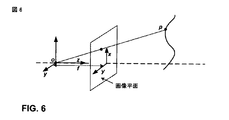
疎にサンプリングされたビューに基づいたビュー合成アルゴリズムは、3Dワーピングの概念に依存することができる。図4は、3Dワーピングの概念を示している。図4に示されるように、3Dワーピングでは、深度およびカメラ・モデルが与えられた場合、参照ビューの
にあるピクセルは、2Dカメラ座標(2D camera coordinate)から、ワールド空間座標系(world-space coordinate system)内の点Pに投影することができる。その後、点Pは、
の方向に沿って、(生成される仮想ビューである)目標ビュー(destination view)に投影することができる。この場合、
の方向は、目標ビューのビュー角度に対応する。投影された座標が
であると仮定することによって、参照ビュー内の
の(異なる色成分の)ピクセル値を、仮想ビュー内の
のピクセル値と見なすことができる。 Pixel value.
時には、参照ビューとして、2つ以上のビューを考慮することもできる。言い換えると、
への上述の投影は、必ずしも1対1の投影になるとは限らない。しかし、2つ以上のピクセルが目標ピクセル
に投影される場合、可視性問題(visibility problem)が生じることがある。他方、1つのピクセルが目標ピクセル
に投影される場合、仮想ビューのピクチャーにホール(hole)が出現すること又は存在することがある。いわゆる可視性問題は、
のピクセル値を構成(construct)するためにどのピクセルを使用すべきかに関する決定を必要とすることがある。ホールがピクチャー内に連続領域として存在する場合、その現象は遮蔽(occlusion)と呼ばれる。それとは異なり、ホールがピクチャー内に疎らに分散する場合、それらのホールはピンホール(pinholes)と呼ばれる。遮蔽は、異なる方向に1つの参照ビューを導入することによって解決することができる。(例えば、ピンホールのピクセル値を決めるための)ピンホール・フィリング(Pinhole filling)は、ホールのための候補として通常は近隣ピクセルを採用する。ピンホール・フィリングのための技法は、遮蔽問題を解決するためにも使用することができる。 It may be necessary to determine which pixels should be used to construct the pixel values of. When holes exist as continuous areas in a picture, the phenomenon is called occlusion. In contrast, if holes are sparsely distributed in a picture, those holes are called pinholes. Occlusion can be resolved by introducing one reference view in different directions. Pinhole filling (eg, for determining pinhole pixel values) typically employs neighboring pixels as candidates for holes. Techniques for pinhole filling can also be used to solve the shielding problem.
u2のピクセル値のために2つ以上のピクセルを考慮する場合、加重平均法を採用することができる。ビュー合成においては、これらのプロセスは再構成(reconstruction)と一般に呼ばれる。可視性、遮蔽、ピンホール・フィリング、および再構成は、全部合わせると、大きな問題となり、3Dワーピングベースのビュー合成を実装する際の障害となる。そのような問題に対処するのに、カメラ・モデルが助けとなることがある。 If more than one pixel is considered for the u 2 pixel value, a weighted average method can be employed. In view composition, these processes are commonly referred to as reconstruction. Visibility, occlusion, pinhole filling, and reconstruction, when combined together, become a big problem and an obstacle to implementing 3D warping based view synthesis. Camera models can help to address such issues.
例えば、内部パラメータ及び外部パラメータ(intrinsic and extrinsic parameters)を含むカメラ・モデルは、ワールド座標系からカメラ平面(camera plane)への変換、またはそれとは逆の変換を説明するために使用することができる。簡潔にするため、本開示で説明および言及されるすべての座標系は直交座標系であるが、本開示の技法は、この点で必ずしも限定されない。 For example, a camera model that includes intrinsic and extrinsic parameters can be used to describe the transformation from the world coordinate system to the camera plane, or vice versa. . For the sake of brevity, all coordinate systems described and referred to in this disclosure are orthogonal coordinate systems, although the techniques of this disclosure are not necessarily limited in this respect.
外部パラメータは、以下の変換に基づいて、ワールド座標内におけるカメラ中心の位置と、カメラの方位(heading)とを定義することができる。
ここで、(x y z)Tは、3Dカメラ座標系における座標であり、(xw yw zw)Tは、ワールド座標系における座標である。行列Aは、4×4行列を含むことができ、以下のように示すことができる直交変換とすることができる。
ここで、Rは、3×3回転行列(rotation matrix)であり、Tは、平行移動(translation)である。この場合、Tはカメラの位置ではない。 Here, R is a 3 × 3 rotation matrix, and T is a translation. In this case, T is not the position of the camera.
3Dカメラ座標系では、z軸は、主光軸(principal optical axis)と呼ばれることがあり、x軸とy軸は、画像平面(image plane)を定義することができる。例えば、図6に示されるように、
は、主光軸を定義することができる。u1を含む、主光軸に直交する平面は、画像平面を定義することができる。 Can define the main optical axis. The plane perpendicular to the main optical axis, including u 1 , can define the image plane.
ワールド座標系は、カメラの3Dカメラ座標系と同じになるように定義することができる。この場合、A=Iである。3Dカメラ座標系が、ワールド座標系から平行移動される場合、以下である。
また、(x y z)T=(xw yw zw)T+TTである。 Further, (x y z) T = (x w y w z w ) T + T T.
内部パラメータは、3Dカメラ座標系から2D画像平面への変換を指定する。この変換のためのモデルは、ピンホール・カメラ・モデルと呼ばれることがあり、図5に概念的に示されている。この場合、Oは、3Dカメラ座標系の原点であり、カメラ平面(またはセンサ平面(sensor plane))の中心を定義することができる。そのようなモデルでは、次のようになる。
ここで、−fは、焦点距離を示し、(u,v)Tは、画像平面内の座標を示す。 Here, -f indicates the focal length, and (u, v) T indicates the coordinates in the image plane.
ピンホール・カメラ・モデルは、焦点距離fが負である点で不便なことがある。この問題に対処するため、ピンホール・カメラ・モデルは、図6に示されるように、フロンタル・ピンホール・カメラ・モデル(frontal pinhole camera model)で表すこともできる。フロンタル・ピンホール・カメラ・モデルでは、関係は、次のようになる。
この変換は、次のように表すことができる。
ここで、(u,v)は、画像平面内の座標であり、Qは、内部パラメータの最も単純な表現である。
と表した場合、ワールド座標系から画像平面への変換全体は、
によって与えられる。 Given by.
いくつかの実装では、内部カメラ・パラメータは、上で説明したよりも複雑になり得る。上でQとして表された変換は、
によって表される。この場合、Skewは、カメラのスキュー係数(skew factor)を示し、(principalx,principaly)Tは、画像平面内の主点(principal point)の座標である。主点は、主光軸が画像平面と交差する点である。fxおよびfyの値は、x軸およびy軸における焦点距離値である。 Represented by In this case, Skew indicates the skew factor of the camera, and (principal x , principal y ) T is the coordinates of the principal point in the image plane. The principal point is a point where the principal optical axis intersects the image plane. The value of f x and f y is the focal length value in x-axis and y-axis.
また、いくつかの実装では、外部カメラ・パラメータも、上で説明したよりも複雑になり得る。より現実的なケースでは、例えば、Rは、xz平面における回転のみを定義することができ、以下のように表すことができる。
立体視ビデオでは、カメラは、同じ内部パラメータを有することができる。これは、例えば、2つのカメラの間に平行移動のみが存在し、カメラの一方がワールド座標系に合致(aligned)している場合とすることができる。この場合、R=I、T=0であり、またu1=fxw/zw、v1=fyw/zwである。第2のカメラが第1のカメラと平行に配置される場合、R=I、T=(d 0 0)Tである。この場合、以下を導出することができる。
fd/zwはまた視差(disparity)と呼ばれる。この場合の3Dワーピングは、視差の計算しか必要としないことがあるが、先に言及した問題は依然として存在し得る。 fd / z w is also called disparity. Although 3D warping in this case may only require parallax calculations, the problems mentioned above may still exist.
各色成分(color component)についての各ピクセルの値は、量子化して8ビットで表して記憶されるので、限られたダイナミック・レンジを用いて深度値を提示することが必要なことがある。8ビットのダイナミック・レンジの実装では、深度値は、例えば、0〜255(0および255は除く)(exclusive)とすることができる。深度値は、大きな範囲の中で変化することができる。しかし、一般に、最近深度値と最遠深度値は、それぞれ0と255にマッピングされ、他の任意の深度値は、0から255までの範囲の外の(outside)値にマッピングすべきである。 Since the value of each pixel for each color component is quantized and stored in 8 bits, it may be necessary to present the depth value using a limited dynamic range. In an 8-bit dynamic range implementation, the depth value can be, for example, 0-255 (excluding 0 and 255) (exclusive). The depth value can vary within a large range. However, in general, the nearest depth value and the farthest depth value are mapped to 0 and 255, respectively, and any other depth value should be mapped to an outside value in the range of 0 to 255.
以下にいくつかの典型的な深度値制限法(depth value qualification methods)を挙げる。
上記の2つの式において、vは、[0,255]に定量化された値であり、zは、1バイトで記憶できる深度である。値zは、[0,255]に正規化することができる。通常は、カメラに近いピクセルほど、より大きな値をとり、深度が大きなピクセルほど、[0,255]のより小さな値に変換される。したがって、深度値を[znear,zfar]から[0,255]に線形変換することが望ましいことがあり、znearは255にマッピングされ、zfarは0にマッピングされる。これが、上に示した式(9)の考え方である。変換を達成する他の方法は、深度の逆数値を[1/zfar,1/znear]から[0,255]に線形変換することであり、1/znearは255にマッピングされ、1/zfarは0にマッピングされる。この他の方法が、上に示した式(10)の考え方である。 In the above two equations, v is a value quantified to [0, 255], and z is a depth that can be stored in 1 byte. The value z can be normalized to [0, 255]. Normally, pixels closer to the camera take larger values, and pixels with a larger depth are converted to smaller values of [0,255]. Therefore, it may be desirable to linearly transform the depth value from [z near , z far ] to [0, 255], where z near is mapped to 255 and z far is mapped to 0. This is the idea of equation (9) shown above. Another way to achieve the transformation is to linearly transform the inverse depth value from [1 / z far , 1 / z near ] to [0, 255], where 1 / z near is mapped to 255 and 1 / Z far is mapped to 0. Another method is the idea of the equation (10) shown above.
H.264/AVCに基づいた2Dビデオ通信システムは、広く配備されているが、いかなる3Dサポートも考慮されていない。そのようなシステムで配信される2Dコンテンツのほとんどで、3Dビデオが望まれる場合、いくつかの問題が生じることがある。特に、ビデオ・コンテンツは、3Dビデオソースを有さないことがあり、3Dビデオソースは、複数カメラシステムによって一般にキャプチャされ、または3Dモデルから変換されさえもする。ビデオ・コンテンツが3Dビデオソースからのものでない場合、復号器で何らかの処理を行った後、そのようなビデオ・コンテンツを3D表示用に使用できるかどうかを示すシグナリングを欠いていることがある。 H. H.264 / AVC-based 2D video communication systems are widely deployed but do not consider any 3D support. Several problems may arise when 3D video is desired for most of the 2D content delivered in such systems. In particular, video content may not have a 3D video source, and the 3D video source is typically captured by a multiple camera system or even converted from a 3D model. If the video content is not from a 3D video source, after performing some processing at the decoder, it may lack signaling that indicates whether such video content can be used for 3D display.
H.264/AVCで符号化された2Dコンテンツの3D表示が可能である場合、既存のビュー(existing view)からエクストラ・ビュー(extra view)を生成するときに、例えば、カメラ・パラメータ、シーンの深度範囲、または他のパラメータなど、いくつかの副次的情報(side information)を役立てることができる。しかし、そのような情報を現在のH.264/AVCビットストリームに収めて伝達するためのメカニズムが必要なことがある。これを行うために、本開示の技法は、H.264/AVCのSEIメッセージまたは類似のタイプのメッセージを使用することができる。 H. When 3D display of 2D content encoded by H.264 / AVC is possible, when generating an extra view from an existing view (existing view), for example, camera parameters, a depth range of a scene Some side information can be useful, such as, or other parameters. However, such information is not currently available in H.264. H.264 / AVC bitstreams may need a mechanism for transmission. To do this, the techniques of this disclosure are described in H.264. H.264 / AVC SEI messages or similar types of messages can be used.
他の問題または課題は、一般に、エクストラ・ビューが生成されたとき、送信されたビュー及び生成されたビューについて仮定された2つカメラの水平変位(horizontal displacement)のせいで(because)、生成されたビュー内に見えるべきではない領域が存在することである。この望ましくない領域が顕著なアーチファクト(noticeable artifact)を導入する場合、生成されたビュー内にこの領域を表示するのは望ましくないことがある。この問題に対処するため、本開示の技法は、クロップ領域を定義し、これをビットストリームで伝達する能力を提供する。 Other problems or issues are generally generated when an extra view is generated, due to the transmitted view and the two camera horizontal displacements assumed for the generated view. There are areas in the view that should not be visible. If this undesirable region introduces noticeable artifacts, it may not be desirable to display this region in the generated view. To address this issue, the techniques of this disclosure provide the ability to define a crop region and convey it in a bitstream.
いくつかの態様では、本開示の技法は、ビデオフレームからなる2Dシーケンスを含む、例えばH.264/AVCビットストリームなどの、符号化ビデオストリームを変換し、例えば立体表示による、3D方式で表示することを可能にする。本開示によれば、2D−3D変換に必要な情報を通知(indicate)するために、シグナリング・メカニズムが使用される。この場合、復号器は、復号されたオリジナルビデオシーケンスと一緒になって3D表示を可能にする、他のビデオシーケンス(例えば第2のビュー)を生成することができる。 In some aspects, the techniques of this disclosure include a 2D sequence of video frames, e.g. An encoded video stream such as an H.264 / AVC bit stream is converted and can be displayed in a 3D format, for example, by stereoscopic display. According to the present disclosure, a signaling mechanism is used to indicate information required for 2D-3D conversion. In this case, the decoder can generate another video sequence (eg, a second view) that, together with the decoded original video sequence, enables 3D display.
本開示の技法では、2D−3D変換情報が、ビットストリームに収めて提供される。ビットストリームに収められた符号化ビデオ情報は、一般にシーンの2D表現であり、エクストラ・ビューまたは深度マップを含まない。したがって、符号化2Dコンテンツの帯域幅は、2D−3D変換に関連するいかなるSEIメッセージも含まない対応する2Dシーケンスの帯域幅と非常に類似している。場合によっては、2Dビデオシーケンスは、符号化デバイスに事前に記憶され(pre-stored)、そして、キャプチャされず、または符号化デバイスにおいて符号化されない。この場合、2D−3D変換情報は、デフォルト環境に基づいて入力および定義されたカメラ・パラメータを含むことがある。他の場合では、2Dビデオ・コンテンツは、キャプチャすることはできるが、符号化されない。この場合、符号器は、入力としていかなる3Dコンテンツも有さずに、2Dコンテンツを符号化することができる。しかし、2D−3D変換についての知識を有する符号器は、3D変換のために必要な情報を生成することができ、この情報をH.264/AVCビットストリームのSEIメッセージ内に収めることができる。さらに他の場合では、符号化デバイスは、2Dビデオ・コンテンツをキャプチャし、符号化することができる。この場合、符号化デバイスは、おそらくは2Dビデオビットストリームを(例えば復号プロセス中に)分析することによって、2D−3D変換情報を追加することができる。 In the technique of the present disclosure, 2D-3D conversion information is provided in a bit stream. The encoded video information contained in the bitstream is generally a 2D representation of the scene and does not include extra views or depth maps. Thus, the bandwidth of the encoded 2D content is very similar to the bandwidth of the corresponding 2D sequence that does not include any SEI messages related to 2D-3D conversion. In some cases, the 2D video sequence is pre-stored at the encoding device and is not captured or encoded at the encoding device. In this case, the 2D-3D conversion information may include camera parameters that are input and defined based on a default environment. In other cases, 2D video content can be captured but not encoded. In this case, the encoder can encode 2D content without having any 3D content as input. However, an encoder with knowledge of 2D-3D conversion can generate the information necessary for 3D conversion, H.264 / AVC bitstream can be contained in the SEI message. In yet other cases, the encoding device can capture and encode 2D video content. In this case, the encoding device may add 2D-3D conversion information, perhaps by analyzing the 2D video bitstream (eg, during the decoding process).
ビデオ・コンテンツが、2D−3D変換をサポートしないH.264/AVC復号器によって復号される場合、2Dビデオを再構成し、表示することができる。しかし、復号器が2D−3D変換情報をサポートし、したがって、2D−3D変換機能を有する場合、復号器は、復号された2Dビデオシーケンスと関連する2D−3D変換情報とに基づいて、セカンダリ・ビューに関連するフレームを生成することができる。その後、2つのビュー(復号されたビューと生成されたビュー)は、3Dディスプレイに表示することができる。 Video content does not support 2D-3D conversion. When decoded by an H.264 / AVC decoder, 2D video can be reconstructed and displayed. However, if the decoder supports 2D-3D conversion information, and thus has 2D-3D conversion functionality, the decoder may determine whether the secondary 2D-3D conversion information is associated with the decoded 2D video sequence and the associated 2D-3D conversion information. A frame associated with the view can be generated. The two views (decoded view and generated view) can then be displayed on a 3D display.
本開示によれば、3D変換情報は、3Dビデオデータを生成するために2Dシーケンス内のビデオフレームの各々に適用できる一組のパラメータを含む。言及したように、ITU H.264/AVCのSEIメッセージは、この3D変換情報をビットストリームに収めて伝達するための、1つのメカニズムとすることができるが、特に他の規格とともに、他のメッセージまたはメカニズムを使用することもできる。3D変換情報は、以下のいくつかまたはすべてを含むことができる。
1−関連する符号化ビデオシーケンスを3Dに変換できることの表示。
2−重要なカメラ・パラメータ、例えば、カメラの焦点距離、および/または仮想ビューに対応する仮定されたカメラの平行移動。
3−現在のシーンの深度範囲。
4−特殊な処理またはクロッピング(special treatment or cropping)を必要とすることがある、復号ビデオ(オリジナル・ビュー)および仮想ビュー内の領域。
In accordance with this disclosure, the 3D conversion information includes a set of parameters that can be applied to each of the video frames in the 2D sequence to generate 3D video data. As mentioned, ITU H.264. H.264 / AVC SEI messages can be one mechanism for transmitting this 3D conversion information in a bitstream, but other messages or mechanisms can also be used, especially with other standards. . The 3D conversion information can include some or all of the following:
1-Indication that the associated encoded video sequence can be converted to 3D.
2—Assumed camera translation corresponding to important camera parameters, eg, camera focal length, and / or virtual view.
3- The depth range of the current scene.
4- Areas in the decoded video (original view) and virtual view that may require special treatment or cropping.
以下の表1は、3D変換情報(2D−3D変換情報)の一例を、様々なSEIメッセージ・シンタックス要素を含むSEIメッセージ・シンタックスの形式で提供している。
変数u(1)およびue(v)は、H.264/AVC仕様書で定義された変数とすることができる。ここで、u(1)は、ビットストリーム内にフラグを符号化するカテゴリであり、ue(v)は、指数ゴロム(Exponential Golomb)(可変長)符号化を使用して、ビットストリーム内に符号なし整数(unsigned integer)を符号化するカテゴリである。 The variables u (1) and ue (v) It can be a variable defined in the H.264 / AVC specification. Here, u (1) is a category for encoding a flag in the bit stream, and ue (v) is a code in the bit stream using Exponential Golomb (variable length) encoding. This is the category that encodes unsigned integers.
表1の例示的な3D変換情報は、以下で説明するようなセマンティクスを有することができる。存在する場合、このSEIメッセージは、現在のアクセス・ユニットと後続のアクセス・ユニットとを含むターゲット・アクセス・ユニットに、次の2D−3D変換SEIメッセージが届くまで、または符号化ビデオシーケンスの終端に達するまで、復号順に適用することができる。第1の2D−3D変換SEIメッセージは、存在する場合、符号化ビデオシーケンスの第1のアクセス・ユニット内に出現することができる。このSEIメッセージは、存在する場合、復号されたビデオに基づいて他のビューを生成できることを通知することができる。復号されたビデオは、オリジナル・ビューとして定義することができ、復号器によって生成されたセカンダリ・ビューは、生成されたビューと呼ぶことができる。オリジナル・ビューと生成されたビューのために、2つのカメラを仮定することができる。 The exemplary 3D conversion information in Table 1 may have semantics as described below. If present, this SEI message is sent to the target access unit including the current access unit and subsequent access units until the next 2D-3D conversion SEI message arrives, or at the end of the encoded video sequence. It can be applied in decoding order until it reaches. A first 2D-3D conversion SEI message, if present, can appear in the first access unit of the encoded video sequence. This SEI message, if present, can inform that other views can be generated based on the decoded video. The decoded video can be defined as the original view, and the secondary view generated by the decoder can be referred to as the generated view. Two cameras can be assumed for the original view and the generated view.
表1の変数camera_scene_para_present_flagは、1の値に設定された場合、焦点距離、深度範囲値、および2つのカメラの平行移動がSEIメッセージ内に指定されていることを示すことができる。camera_scene_para_present_flagが0に等しい場合、これは、focal_length、near_dapth、far_dapth、およびtranslate_xをいくつかのデフォルト値によって推測できることを示すことができる。一例として、focal_length、near_dapth、far_dapth、およびtranslate_xのデフォルト値は、それぞれ、1000、2000、4000、およびPicWidthInSamplesL/16と定義することができる。camera_scene_para_present_flagが1に等しい場合、焦点距離、深度範囲値、および平行移動値は、ビットストリーム内に明示的に含まれるが、camera_scene_para_present_flagが0に等しい場合、これらの値は、ビットストリーム内に明示的に含まれない。 If the variable camera_scene_para_present_flag in Table 1 is set to a value of 1, it can indicate that the focal length, depth range value, and translation of the two cameras are specified in the SEI message. If camera_scene_para_present_flag is equal to 0, this can indicate that focal_length, near_dapt, far_dapth, and translate_x can be inferred by some default values. As an example, the default values for focal_length, near_dapt, far_dapth, and translate_x can be defined as 1000, 2000, 4000, and PicWidthInSamples L / 16, respectively. If camera_scene_para_present_flag is equal to 1, the focal length, depth range value, and translation value are explicitly included in the bitstream, but if camera_scene_para_present_flag is equal to 0, these values are explicitly included in the bitstream. Not included.
表1の変数left_view_original_flagは、生成されたビューがオリジナル・ビューの左側にあることを示すために、すなわち、生成されたビューのために仮定されたカメラがオリジナル・ビューのオリジナルカメラの左側であることを示すために、1に等しくすることができる。変数left_view_original_flagが0に等しい場合、生成されたビューがオリジナル・ビューの右側にあることを示す。もちろん、これら左右の指示を逆にすることもできる。 The variable left_view_original_flag in Table 1 indicates that the generated view is to the left of the original view, i.e. the camera assumed for the generated view is to the left of the original camera of the original view. Can be equal to 1. If the variable left_view_original_flag is equal to 0, it indicates that the generated view is to the right of the original view. Of course, these left and right instructions can be reversed.
表1の変数dummy_region_flagは、2つのビューのためにダミー領域が存在し、この領域が表示前にクロッピングされることを示すために、1に等しくすることができる。表1の変数focal_lengthは、カメラの焦点距離を指定することができる。一例として、focal_lengthの値は、1以上232−1以下の(inclusive)範囲内にあることができる。表1の変数near_depthは、オリジナル・ビューおよび生成されたビュー内のピクセルの最小深度値を指定する。変数near_depthは、1以上far_depth−1以下の(inclusive)範囲内にあることができる。表1の変数far_depthは、オリジナル・ビューおよび生成されたビュー内のピクセルの最大深度値を指定する。far_depthの値は、near_depth+1以上232−1以下の(inclusive)範囲内にあることができる。 The variable dummy_region_flag in Table 1 can be equal to 1 to indicate that there is a dummy region for the two views and this region is cropped before display. The variable focal_length in Table 1 can specify the focal length of the camera. As an example, the value of focal_length can be in an inclusive range of 1 to 2 32 −1. The variable near_depth in Table 1 specifies the minimum depth value of the pixels in the original view and the generated view. The variable near_depth may be in an inclusive range of 1 to far_depth−1. The variable far_depth in Table 1 specifies the maximum depth value of the pixels in the original view and the generated view. The value of far_depth may be in an inclusive range of near_depth + 1 to 2 32 −1.
表1の変数translate_xは、オリジナル・ビューと生成されたビューについて仮定されたカメラの間の距離を指定する。変数dum_reg_widthは、出力用に使用されない、オリジナル・ビューおよび生成されたビューではクロッピングされる領域の幅を指定し、単位は輝度サンプル(luma samples)の単位である。dum_reg_widthは、dummy_region_flagが1に等しい場合にのみ含まれ得る。 The variable translate_x in Table 1 specifies the distance between the camera assumed for the original view and the generated view. The variable dum_reg_width specifies the width of the cropped area in the original and generated views that are not used for output, and the units are in units of luma samples. dum_reg_width may be included only if dummy_region_flag is equal to 1.
left_view_original_flagが1に等しい場合、出力領域は、水平方向に、両端を含んで0からPicWidthInSamplesL−dum_reg_width−1までの(inclusive)領域にクロッピングされる。left_view_original_flagが0に等しい場合、出力領域は、両端を含んでdum_reg_widthからPicWidthInSamplesL−1までの領域にクロッピングされる(inclusively)。dum_reg_widthの値は、PicWidthInSamplesL/16であると推測することもできる。 When left_view_original_flag is equal to 1, the output region is cropped horizontally (inclusive) from 0 to PicWidthInSamples L- dum_reg_width-1 including both ends. When left_view_original_flag is equal to 0, the output area is cropped into an area including both ends from dum_reg_width to PicWidthInSamples L- 1. It can also be assumed that the value of dum_reg_width is PicWidthInSamples L / 16.
例えばSEIメッセージ内の、3D変換情報は、エクストラ・ビューを生成するために復号器においてビュー合成のために適用されるアルゴリズムを必ずしも指定しない。しかし、3Dワーピングベースのアルゴリズムでは、3Dワーピングのために上記の式(8)を使用することができ、この式は、実際に、オリジナル・ビュー内の1つのピクセルを仮想ビューにマッピングする。この場合、zwはオリジナル・ビュー内のピクセルの深度であって、[near_depth,far_depth]の区間内にあり、fはfocal_lengthであり、dの絶対値がtranslate_xである。 For example, the 3D transformation information in the SEI message does not necessarily specify the algorithm applied for view synthesis at the decoder to generate an extra view. However, 3D warping based algorithms can use equation (8) above for 3D warping, which actually maps one pixel in the original view to the virtual view. In this case, z w is a depth of a pixel in the original view, is in the interval of [near_depth, far_depth], f is focal_length, the absolute value of d is Translate_x.
代替として、focal_length、near_depth、far_depth、およびtranslate_xは、IEC 60559仕様書または他の通信プロトコルによる、符号付き倍精度値(signed double values)として伝達(signaled)することもできる。IEC 60559では、値Xは、符号s(+/−)、N(仮数部)、およびE(指数部)の3つの部分で伝達される。値Xの計算の1つの可能な実装が、以下の疑似コード(pseudo-code)で説明されている。
ここで、Xは計算される変数であり、s、N、およびEは、計算される各変数に関連する符号、指数、および仮数シンタックス要素に対応し、Mは、M=bin2float(N)、0≦M<1である。各カメラ・パラメータ変数と対応するシンタックス要素との間の関連付けは、多種多様な実装に依存する。 Where X is a variable to be calculated, s, N, and E correspond to the sign, exponent, and mantissa syntax elements associated with each variable to be calculated, and M is M = bin2float (N) 0 ≦ M <1. The association between each camera parameter variable and the corresponding syntax element depends on a wide variety of implementations.
また、上記のパラメータに加えて、追加のパラメータも使用することができる。例えば、収束画像平面(convergence image plane)から2つの異なるカメラまでの仮定距離を定量化する収束深度値(convergence-depth value)を、一組のパラメータに含めることができる。表1のパラメータを用いる場合、収束深度値は、無限であると仮定することができるが、他の場合は、収束深度値を一組のパラメータに明確に含めることができる。 In addition to the above parameters, additional parameters can also be used. For example, a set of parameters may include a convergence-depth value that quantifies an assumed distance from a convergence image plane to two different cameras. When using the parameters in Table 1, the convergence depth value can be assumed to be infinite, but in other cases, the convergence depth value can be explicitly included in the set of parameters.
以下の疑似コードは、分数の2進表現を対応する浮動小数点数に変換する、bin2float()関数の一例を提供している。関数M=bin2float(N)の疑似コードは、以下のように与えることができる。
代替として、より多くのカメラ・パラメータを伝達することもできる。例えば、x軸およびy軸についての異なる焦点距離fxおよびfyと、スキュー係数とを含み、または式(6)に示されるような主点すらも含む、内部パラメータを伝達することができる。加えて、生成されるビューについて仮定されるカメラは、xz平面における回転を有することができ、そのため、この値、すなわち式(7)に示されるようなθも伝達することができる。 Alternatively, more camera parameters can be communicated. For example, a different focal length f x and f y for x-axis and y-axis, and a skew coefficient, or including even the principal points, as shown in equation (6), it is possible to transmit the internal parameter. In addition, the assumed camera for the generated view can have a rotation in the xz plane, so it can also transmit this value, ie θ as shown in equation (7).
図7は、本開示による、ビデオ符号器50を含むデバイスによって実行できる符号化プロセスを示すフロー図である。図7に示されるように、ビデオ符号器50は、ビデオフレームからなる2Dシーケンスを符号化し(101)、2D−3D変換ユニット36は、ビデオ符号器を用いて3D変換情報を符号化し(102)、3D変換情報は、3Dビデオデータを生成するために2Dシーケンス内のビデオフレームの各々に適用できる一組のパラメータを含む。その後、ビデオ符号器50を含むデバイスは、符号化2Dシーケンスを3D変換情報とともに伝達することができる(103)。図1を参照すると、例えば、ビデオ符号器22は、ビデオ符号器50に対応することができる。この場合、ソース・デバイス12は、モデム23および送信機24を介して、符号化2Dシーケンスを3D変換情報とともに伝達することができ(103)、モデム23および送信機24は、符号分割多元接続(CDMA)などの無線プロトコルに従って、情報を変調し、送信する。
FIG. 7 is a flow diagram illustrating an encoding process that may be performed by a device including a
2Dシーケンスを符号化する際、ビデオ符号器50は、ITU H.264ビデオ符号化規格に従って、2Dシーケンスを符号化することができる。この場合、3D変換情報を符号化することは、上で説明したようなITU H.264ビデオ符号化規格によってサポートされる1つまたは複数のSEIメッセージ内に、3D変換情報を符号化することを含むことができる。2Dシーケンスは、第1の2Dシーケンス(例えばオリジナルシーケンス)と呼ばれることもある。ビデオフレーム(例えばセカンダリ・ビュー)からなる第2の2Dシーケンスを生成するために、第1の2Dシーケンス内のビデオフレームの各々に、一組のパラメータを適用することができ、第1及び第2の2Dシーケンスは、一緒になって、3D立体視ビデオシーケンスを定義する。
When encoding a 2D sequence, the
3D変換情報は、3Dビデオデータを生成するために2Dシーケンスに適用される3D変換プロセスを識別する情報を含むことができる。上で説明したように、3D変換情報は、2Dシーケンスのキャプチャに関連するカメラ・パラメータおよび値を含むことができる。例えば、3D変換情報は、2Dシーケンスをキャプチャしたカメラに関連する焦点距離を表す焦点距離値、3Dビデオデータの最小深度を指定する近深度値、3Dビデオデータの最大深度を指定する遠深度値、および3Dビデオデータに関連する2つのカメラ間の仮定距離を定量化する平行移動値を含むことができる。 The 3D conversion information can include information identifying a 3D conversion process applied to the 2D sequence to generate 3D video data. As described above, the 3D conversion information can include camera parameters and values associated with capturing a 2D sequence. For example, the 3D conversion information includes a focal length value that represents a focal length associated with a camera that has captured a 2D sequence, a near depth value that specifies a minimum depth of 3D video data, a far depth value that specifies a maximum depth of 3D video data, And a translation value that quantifies the assumed distance between the two cameras associated with the 3D video data.
3D変換情報は、3D変換情報に明示的な一組の3Dパラメータが含まれるかどうか、またはデフォルトの一組の3Dパラメータを使用すべきかどうかを指示するフラグを含むことができる。加えて、3D変換情報は、2Dシーケンスの第2のビューを2Dシーケンスの左側に生成すべきか、それとも右側に生成すべきかを指示するフラグも含むことができる。また、3D変換情報は、3Dビデオデータから除去すべきクロップ領域を識別するフラグも含むことができる。 The 3D conversion information may include a flag that indicates whether the 3D conversion information includes an explicit set of 3D parameters or whether a default set of 3D parameters should be used. In addition, the 3D conversion information may also include a flag indicating whether a second view of the 2D sequence should be generated on the left side or the right side of the 2D sequence. The 3D conversion information can also include a flag for identifying a crop area to be removed from the 3D video data.
一例では、第1のフラグは、3D変換情報に明示的な一組の3Dパラメータが含まれるかどうか、またはデフォルトの一組の3Dパラメータを使用すべきかどうかを指示することができ、明示的な一組の3Dパラメータは、第1のフラグが設定されているときに、3D変換情報に含まれる。第2のフラグは、2Dシーケンスの第2のビューを2Dシーケンスの左側に生成すべきか、それとも右側に生成すべきかを指示することができ、第3のフラグは、3Dビデオデータからクロップ領域を除去すべきかどうかを識別することができ、クロップ領域を定義する情報は、第3のフラグが設定されているときに、3D変換情報に含まれる。 In one example, the first flag can indicate whether the explicit set of 3D parameters is included in the 3D conversion information, or whether the default set of 3D parameters should be used. The set of 3D parameters is included in the 3D conversion information when the first flag is set. The second flag can indicate whether the second view of the 2D sequence should be generated on the left or right side of the 2D sequence, and the third flag removes the crop area from the 3D video data Whether to be able to be identified and information defining the crop area is included in the 3D conversion information when the third flag is set.
図8は、本開示による、復号プロセスを示すフロー図である。ビデオ復号器70は、符号化2Dシーケンスを3D変換情報とともに受け取り(111)、2Dシーケンスを復号する(112)。例えば、エントロピー復号ユニット72は、2Dシーケンスの残差ビデオブロックの量子化された係数を生成するために、ビットストリームのエントロピー復号を実行することができる。エントロピー復号ユニット72は、ビットストリームからシンタックス要素を解析して取り出し、そのようなシンタックス要素をビデオ復号器70の様々なユニットに転送することができる。エントロピー符号化ユニット72は、SEIメッセージ内の任意のシンタックスを識別するために、そのようなメッセージを解析(parse)することができる。動き情報(例えば動きベクトル)および他のシンタックス情報を、予測ユニット75に転送することができる。予測ユニット75は、符号化の際に使用された予測ブロックを識別するために、動き情報または他のシンタックス要素を使用する。インターベースの復号の場合、予測データの1つまたは複数のリストから予測ブロックを生成するために、動き補償プロセスにおいて、動きベクトルを適用することができる。インターベースの復号の場合、シンタックスは、イントラモードを含むことができ、このモードは、復号されるビデオブロックのフレームと同じフレームに属するデータに基づいて、予測ブロックをどのように生成すべきかを定義することができる。
FIG. 8 is a flow diagram illustrating a decoding process according to this disclosure. Video decoder 70 receives the encoded 2D sequence along with the 3D conversion information (111) and decodes the 2D sequence (112). For example,
逆量子化ユニット76は、エントロピー復号ユニット72から受け取ったデータを逆量子化し、逆変換ユニットは、ピクセル領域における残差ブロックを生成するために、逆変換を実行する。その後、加算器79は、オリジナル・ビデオブロックの再構成を生成するために、残差ブロックを、予測ユニット75によって生成された予測ブロックと合成する。オリジナル・ビデオブロックの再構成は、メモリ74内に記憶することができ、および/または復号された2Dビデオデータとしてディスプレイに出力することができる。このようにして、ビデオフレームを再構成し、最終的にメモリ74内にビデオフレームからなる2Dシーケンス全体を再構成するために、多くのビデオブロックを復号することができる。
Inverse quantization unit 76 inverse quantizes the data received from
ビデオ復号器70は、それが3Dビデオをサポートするかどうかを判定することができる(113)。言い換えると、ビデオ復号器70は、それが2D−3D変換ユニット79を含むかどうかを判定することができる。これは明示的に判定することができ、または代替として、ビデオ復号器70は、2D−3D変換ユニット79を含まない場合は、本質的に2D復号に従って動作することができる。ビデオ復号器70が2D−3D変換ユニット79を含む場合、3Dビデオを生成することができる。
Video decoder 70 may determine whether it supports 3D video (113). In other words, the video decoder 70 can determine whether it includes a 2D-
したがって、ビデオ復号器70が3Dビデオをサポートしない場合(113のno分岐)、ビデオ復号器70は、復号された2Dシーケンスを2Dディスプレイに出力することができる(114)。他方、ビデオ復号器70が3Dビデオをサポートする場合(113のyes分岐)、2D−3D変換ユニット79は、3Dビデオシーケンスを生成するために、復号された2Dシーケンスに3D変換情報を適用し(115)、その後、その結果は、ビデオ復号器70から3Dディスプレイに出力することができる(116)。このようにして、3D変換情報とともに伝達された2Dシーケンスは、2D−3D変換をサポートする復号デバイスでは、3Dビデオをサポートすることができるが、2Dビデオだけしかサポートしないレガシデバイスでは、従来の2Dビデオもサポートすることができる。
Thus, if video decoder 70 does not support 3D video (113 no branch), video decoder 70 may output the decoded 2D sequence to a 2D display (114). On the other hand, if video decoder 70 supports 3D video (113 yes branch), 2D-
また他の例では、2Dシーケンスとともに3D変換情報を伝達する必要がないこともある。例えば、符号器または復号器は、3Dビデオデータを生成するために、本明細書で説明した3D変換情報を、記憶されたまたは受け取った2Dシーケンスに単純に適用することもある。したがって、本開示は、3Dビデオデータを生成するために2Dシーケンスに3D変換情報を適用する、方法、コンピュータ読み取り可能な記憶媒体、装置、およびデバイスを企図している。ここで、3D変換情報は、3Dビデオデータを生成するために2Dシーケンス内の各ビデオフレームに適用できる一組のパラメータを含む。 In another example, it may not be necessary to transmit the 3D conversion information together with the 2D sequence. For example, an encoder or decoder may simply apply the 3D conversion information described herein to a stored or received 2D sequence to generate 3D video data. Accordingly, the present disclosure contemplates methods, computer-readable storage media, apparatus, and devices that apply 3D conversion information to 2D sequences to generate 3D video data. Here, the 3D conversion information includes a set of parameters that can be applied to each video frame in the 2D sequence to generate 3D video data.
本開示の技法は、モバイルフォンなどの無線通信デバイスハンドセット、集積回路(IC)、または一組のIC(すなわちチップセット)を含む、多種多様なデバイスまたは装置において実装することができる。いずれのコンポーネント、モジュール、またはユニットも、機能態様を強調して説明および提供されており、異なるハードウェアユニットによる実現を必ずしも必要としない。本明細書で説明した技法は、ハードウェア、ソフトウェア、ファームウェア、またはそれらの任意の組合せで実装することもできる。モジュール、ユニット、またはコンポーネントとして説明されたいずれの特徴も、一緒にして統合論理デバイス内で、または切り離して個別の相互動作可能な論理デバイス(interoperable logic devices)として実装することができる。場合によっては、様々な特徴は、集積回路チップまたはチップセットなどの、集積回路デバイスとして実装することができる。 The techniques of this disclosure may be implemented in a wide variety of devices or apparatuses, including a wireless communication device handset such as a mobile phone, an integrated circuit (IC), or a set of ICs (ie, a chipset). Any component, module, or unit has been described and provided with emphasis on functional aspects and does not necessarily require realization by different hardware units. The techniques described herein may also be implemented in hardware, software, firmware, or any combination thereof. Any of the features described as modules, units, or components may be implemented together in an integrated logic device or separately as separate interoperable logic devices. In some cases, the various features can be implemented as an integrated circuit device, such as an integrated circuit chip or chipset.
ソフトウェアで実装する場合、本開示の技法は、プロセッサにおいて実行された場合に、上で説明した方法の1つまたは複数を実行する命令を含む、コンピュータ読み取り可能な媒体によって少なくとも部分的に実現することができる。コンピュータ読み取り可能な媒体は、コンピュータ読み取り可能な記憶媒体を含むことができ、パッケージング材料を含み得るコンピュータプログラム製品の一部を形成することができる。コンピュータ読み取り可能な記憶媒体は、同期ダイナミックランダムアクセスメモリ(SDRAM)などのランダムアクセスメモリ(RAM)、リードオンリメモリ(ROM)、不揮発性ランダムアクセスメモリ(NVRAM)、電気的消去可能プログラマブルリードオンリメモリ(EEPROM)、フラッシュメモリ、および磁気的または光学的記憶媒体などを含むことができる。本開示の技法は、追加または代替として、命令またはデータ構造の形式をとるコードを搬送または伝達し、コンピュータによるアクセス、読取り、および/または実行が可能な、コンピュータ読み取り可能な通信媒体によって少なくとも部分的に実現することができる。 When implemented in software, the techniques of this disclosure may be implemented at least in part by a computer-readable medium that includes instructions that, when executed on a processor, perform one or more of the methods described above. Can do. Computer-readable media can include computer-readable storage media and can form part of a computer program product that can include packaging material. Computer-readable storage media include random access memory (RAM) such as synchronous dynamic random access memory (SDRAM), read only memory (ROM), nonvolatile random access memory (NVRAM), electrically erasable programmable read only memory ( EEPROM), flash memory, and magnetic or optical storage media. The techniques of this disclosure may additionally or alternatively be carried at least in part by a computer-readable communication medium that carries or conveys code in the form of instructions or data structures and is accessible, readable, and / or executable by a computer. Can be realized.
コードまたは命令は、1つまたは複数のデジタル信号プロセッサ(DSP)、汎用マイクロプロセッサ、特定用途向け集積回路(ASIC)、フィールドプログラマブルゲートアレイ(FPGA)、または他の等価な統合もしくは個別論理回路など、1つまたは複数のプロセッサによって実行することができる。したがって、「プロセッサ」という用語は、本明細書で使用される場合、上記の構造のいずれか、または本明細書で説明した技法の実装に適した他の任意の構造を指すことができる。加えて、幾つかの態様において、本明細書で説明した機能は、符号化および復号のために構成された専用ソフトウェアモジュールまたはハードウェアモジュール内で提供することができ、または組合せビデオコーデック内に組み込むことができる。また、本開示の技法は、1つまたは複数の回路または論理要素において完全に実装することができる。 The code or instructions may include one or more digital signal processors (DSPs), general purpose microprocessors, application specific integrated circuits (ASICs), field programmable gate arrays (FPGAs), or other equivalent integrated or discrete logic circuits, etc. It can be executed by one or more processors. Thus, the term “processor”, as used herein, can refer to any of the structures described above, or any other structure suitable for implementation of the techniques described herein. In addition, in some aspects, the functionality described herein can be provided in a dedicated software module or hardware module configured for encoding and decoding, or incorporated in a combined video codec. be able to. Also, the techniques of this disclosure may be fully implemented in one or more circuits or logic elements.
本開示は、本開示で説明した技法の1つまたは複数を実装する回路を含む様々な集積回路デバイスのいずれをも意図している。そのような回路は、単一の集積回路チップにおいて、またはいわゆるチップセット内の複数の相互動作可能な集積回路チップにおいて提供することができる。そのような集積回路デバイスは、様々なアプリケーションで使用することができ、そのいくつかは、モバイル電話ハンドセットなどの無線通信デバイスにおける使用を含むことができる。 This disclosure contemplates any of a variety of integrated circuit devices that include circuitry that implements one or more of the techniques described in this disclosure. Such a circuit can be provided in a single integrated circuit chip or in a plurality of interoperable integrated circuit chips in a so-called chipset. Such integrated circuit devices can be used in a variety of applications, some of which can include use in wireless communication devices such as mobile telephone handsets.
様々な例が、本開示において説明された。これらの例および他の例は、以下の特許請求の範囲内にある。 Various examples have been described in this disclosure. These and other examples are within the scope of the following claims.
様々な例が、本開示において説明された。これらの例および他の例は、以下の特許請求の範囲内にある。
以下に、本願出願の当初の特許請求の範囲に記載された各請求項に対応する発明を付記する。
[1]ビデオ符号器においてビデオフレームからなる2次元(2D)シーケンスを符号化することと、前記ビデオ符号器を用いて3次元(3D)変換情報を符号化することと、ここで、前記3D変換情報は、3Dビデオデータを生成するために前記2Dシーケンス内の前記ビデオフレームの各々に適用できる一組のパラメータを含む、前記符号化2Dシーケンスを前記3D変換情報とともに伝達することを含む方法。
[2]前記2Dシーケンスを符号化することは、ITU H.264ビデオ符号化規格に従って、前記2Dシーケンスを符号化することを含み、前記3D変換情報を符号化することは、前記ITU H.264ビデオ符号化規格によってサポートされる1つまたは複数の補助拡張情報(SEI)メッセージ内に前記3D変換情報を符号化することを含む[1]に記載の方法。
[3]前記2Dシーケンスは、第1の2Dシーケンスであり、前記一組のパラメータは、ビデオフレームからなる第2の2Dシーケンスを生成するために、前記第1の2Dシーケンス内の前記ビデオフレームの各々に適用されることができ、前記第1及び第2の2Dシーケンスは、一緒になって、3D立体視ビデオシーケンスを定義する、[1]に記載の方法。
[4]前記3D変換情報は、前記3Dビデオデータを生成するために前記2Dシーケンスに適用される3D変換プロセスを識別する情報を含む、[1]に記載の方法。
[5]前記3D変換情報は、カメラ・パラメータと、前記2Dシーケンスのキャプチャに関連する値とを含む、[1]に記載の方法。
[6]前記3D変換情報は、前記2Dシーケンスをキャプチャしたカメラに関連する焦点距離を示す焦点距離値と、前記3Dビデオデータにおける最小深度を指定する近深度値と、前記3Dビデオデータにおける最大深度を指定する遠深度値と、前記3Dビデオデータに関連する2つのカメラ間の仮定距離を定量化する平行移動値とを含む、[1]に記載の方法。
[7]前記3D変換情報は、前記2Dシーケンスをキャプチャしたカメラに関連する焦点距離を示す焦点距離値と、前記3Dビデオデータにおける最小深度を指定する近深度値と、前記3Dビデオデータにおける最大深度を指定する遠深度値と、前記3Dビデオデータに関連する2つのカメラ間の仮定距離を定量化する平行移動値と、収束画像平面から前記2つのカメラまでの仮定距離を定量化する収束深度値とを含む、[1]に記載の方法。
[8]前記3D変換情報は、3D変換情報に明示的な一組の3Dパラメータが含まれるか又はデフォルトの一組の3Dパラメータを使用すべきかを指示するフラグを含む、[1]に記載の方法。
[9]前記3D変換情報は、前記2Dシーケンスの第2のビューを前記2Dシーケンスの左側に生成すべきか、それとも右側に生成すべきかを指示するフラグを含む、[1]に記載の方法。
[10]前記3D変換情報は、前記3Dビデオデータから除去すべきクロップ領域を識別するフラグを含む、[1]に記載の方法。
[11]前記3D変換情報は、前記3D変換情報に明示的な一組の3Dパラメータが含まれるか又はデフォルトの一組の3Dパラメータを使用すべきかを指示する第1のフラグであって、前記明示的な一組の3Dパラメータは、前記第1のフラグが設定されている場合に、前記3D変換情報に含まれる、第1のフラグと、前記2Dシーケンスの第2のビューを前記2Dシーケンスの左側に生成すべきか、それとも右側に生成すべきかを指示する第2のフラグと、前記3Dビデオデータからクロップ領域を除去すべきかどうかを識別する第3のフラグであって、前記クロップ領域を定義する情報は、前記第3のフラグが設定されている場合に、前記3D変換情報に含まれる、第3のフラグとを含む、[1]に記載の方法。
[12]ビデオ復号器においてビデオフレームからなる2次元(2D)シーケンスを受け取ることと、前記ビデオ復号器において前記2Dシーケンスとともに3次元(3D)変換情報を受け取ることと、ここで、前記3D変換情報は、3Dビデオデータを生成するために前記2Dシーケンス内の前記ビデオフレームの各々に適用できる一組のパラメータを含む、前記ビデオ復号器を用いて前記2Dシーケンスを復号することと、前記2Dシーケンス及び前記3D変換情報に基づいて、前記ビデオ復号器を用いて前記3Dビデオデータを生成することとを含む方法。
[13]前記2Dシーケンスは、ITU H.264ビデオ符号化規格に従って符号化され、前記3D変換情報は、前記ITU H.264ビデオ符号化規格によってサポートされる1つまたは複数の補助拡張情報(SEI)メッセージに収めて受け取られる、[12]に記載の方法。
[14]前記2Dシーケンスは、第1の2Dシーケンスであり、前記一組のパラメータは、ビデオフレームからなる第2の2Dシーケンスを生成するために、前記第1の2Dシーケンス内の前記ビデオフレームの各々に適用されることができ、前記第1及び第2の2Dシーケンスは、一緒になって、3D立体視ビデオシーケンスを定義し、前記3Dビデオデータを生成することは、前記3D立体視ビデオシーケンスを定義するために、前記第2の2Dシーケンスを生成することを含む、[12]に記載の方法。
[15]前記3D変換情報は、前記3Dビデオデータを生成するために前記2Dシーケンスに適用される3D変換プロセスを識別する情報を含む、[12]に記載の方法。
[16]前記3D変換情報は、カメラ・パラメータと、前記2Dシーケンスのキャプチャに関連する値とを含む、[12]に記載の方法。
[17]前記3D変換情報は、前記2Dシーケンスをキャプチャしたカメラに関連する焦点距離を示す焦点距離値と、前記3Dビデオデータにおける最小深度を指定する近深度値と、前記3Dビデオデータにおける最大深度を指定する遠深度値と、前記3Dビデオデータに関連する2つのカメラ間の仮定距離を定量化する平行移動値とを含む、[12]に記載の方法。
[18]前記3D変換情報は、前記2Dシーケンスをキャプチャしたカメラに関連する焦点距離を示す焦点距離値と、前記3Dビデオデータにおける最小深度を指定する近深度値と、前記3Dビデオデータにおける最大深度を指定する遠深度値と、前記3Dビデオデータに関連する2つのカメラ間の仮定距離を定量化する平行移動値と、収束画像平面から前記2つのカメラまでの仮定距離を定量化する収束深度値とを含む、[12]に記載の方法。
[19]前記3D変換情報は、3D変換情報に明示的な一組の3Dパラメータが含まれるか又はデフォルトの一組の3Dパラメータを使用すべきかを指示するフラグを含む、[12]に記載の方法。
[20]前記3D変換情報は、前記2Dシーケンスの第2のビューを前記2Dシーケンスの左側に生成すべきか、それとも右側に生成すべきかを指示するフラグを含む、[12]に記載の方法。
[21]前記3D変換情報は、前記3Dビデオデータから除去すべきクロップ領域を識別するフラグを含む、[12]に記載の方法。
[22]前記3D変換情報は、前記3D変換情報に明示的な一組の3Dパラメータが含まれるか又はデフォルトの一組の3Dパラメータを使用すべきかを指示する第1のフラグであって、前記明示的な一組の3Dパラメータは、前記第1のフラグが設定されている場合に、前記3D変換情報に含まれる、第1のフラグと、前記2Dシーケンスの第2のビューを前記2Dシーケンスの左側に生成すべきか、それとも右側に生成すべきかを指示する第2のフラグと、前記3Dビデオデータからクロップ領域を除去すべきかどうかを識別する第3のフラグであって、前記クロップ領域を定義する情報は、前記第3のフラグが設定されている場合に、前記3D変換情報に含まれる、第3のフラグとを含む、[12]に記載の方法。
[23]受信デバイスが前記3Dビデオデータを生成及びレンダリングできるかどうかについて、判定することと、前記受信デバイスが前記3Dビデオデータを生成及びレンダリングできる場合に、前記2Dシーケンス及び前記3D変換情報に基づいて、前記3Dビデオデータを生成し、レンダリングすることと、前記受信デバイスが前記3Dビデオデータを生成又はレンダリングできない場合に、前記2Dシーケンスをレンダリングすることを更に含む[12]に記載の方法。
[24]ビデオフレームからなる2次元(2D)シーケンスを符号化し、前記2Dシーケンスとともに3次元(3D)変換情報を符号化するビデオ符号器を含み、前記3D変換情報は、3Dビデオデータを生成するために前記2Dシーケンス内の前記ビデオフレームの各々に適用できる一組のパラメータを含む、装置。
[25]前記符号化2Dシーケンスを前記3D変換情報とともに他のデバイスに伝達する送信機を更に含む[24]に記載の装置。
[26]前記ビデオ符号器は、ITU H.264ビデオ符号化規格に従って、前記2Dシーケンスを符号化し、前記ITU H.264ビデオ符号化規格によってサポートされる1つまたは複数の補助拡張情報(SEI)メッセージ内に前記3D変換情報を符号化する、[24]に記載の装置。
[27]前記2Dシーケンスは、第1の2Dシーケンスであり、前記一組のパラメータは、ビデオフレームからなる第2の2Dシーケンスを生成するために、前記第1の2Dシーケンス内の前記ビデオフレームの各々に適用されることができ、前記第1及び第2の2Dシーケンスは、一緒になって、3D立体視ビデオシーケンスを定義する、[24]に記載の装置。
[28]前記3D変換情報は、前記3Dビデオデータを生成するために前記2Dシーケンスに適用される3D変換プロセスを識別する情報を含む、[24]に記載の装置。
[29]前記3D変換情報は、カメラ・パラメータと、前記2Dシーケンスのキャプチャに関連する値とを含む、[24]に記載の装置。
[30]前記3D変換情報は、前記2Dシーケンスをキャプチャしたカメラに関連する焦点距離を示す焦点距離値と、前記3Dビデオデータにおける最小深度を指定する近深度値と、前記3Dビデオデータにおける最大深度を指定する遠深度値と、前記3Dビデオデータに関連する2つのカメラ間の仮定距離を定量化する平行移動値とを含む、[24]に記載の装置。
[31]前記3D変換情報は、前記2Dシーケンスをキャプチャしたカメラに関連する焦点距離を示す焦点距離値と、前記3Dビデオデータにおける最小深度を指定する近深度値と、前記3Dビデオデータにおける最大深度を指定する遠深度値と、前記3Dビデオデータに関連する2つのカメラ間の仮定距離を定量化する平行移動値と、収束画像平面から前記2つのカメラまでの仮定距離を定量化する収束深度値とを含む、[24]に記載の装置。
[32]前記3D変換情報は、3D変換情報に明示的な一組の3Dパラメータが含まれるか又はデフォルトの一組の3Dパラメータを使用すべきかを指示するフラグを含む、[24]に記載の装置。
[33]前記3D変換情報は、前記2Dシーケンスの第2のビューを前記2Dシーケンスの左側に生成すべきか、それとも右側に生成すべきかを指示するフラグを含む、[24]に記載の装置。
[34]前記3D変換情報は、前記3Dビデオデータから除去すべきクロップ領域を識別するフラグを含む、[24]に記載の装置。
[35]前記3D変換情報は、前記3D変換情報に明示的な一組の3Dパラメータが含まれるか又はデフォルトの一組の3Dパラメータを使用すべきかを指示する第1のフラグであって、前記明示的な一組の3Dパラメータは、前記第1のフラグが設定されている場合に、前記3D変換情報に含まれる、第1のフラグと、前記2Dシーケンスの第2のビューを前記2Dシーケンスの左側に生成すべきか、それとも右側に生成すべきかを指示する第2のフラグと、前記3Dビデオデータからクロップ領域を除去すべきかどうかを識別する第3のフラグであって、前記クロップ領域を定義する情報は、前記第3のフラグが設定されている場合に、前記3D変換情報に含まれる、第3のフラグとを含む、[24]に記載の装置。
[36]集積回路と、マイクロプロセッサと、前記ビデオ符号器を含む無線通信デバイスとのうちの少なくとも一つを含む[24]に記載の装置。
[37]ビデオ復号器を含む装置において、前記ビデオ復号器は、ビデオフレームからなる2次元(2D)シーケンスを受け取り、前記2Dシーケンスとともに3次元(3D)変換情報を受け取り、ここで、前記3D変換情報は、3Dビデオデータを生成するために前記2Dシーケンス内の前記ビデオフレームの各々に適用できる一組のパラメータを含む、前記2Dシーケンスを復号し、前記2Dシーケンス及び前記3D変換情報に基づいて、前記3Dビデオデータを生成する装置。
[38]前記2Dシーケンスは、ITU H.264ビデオ符号化規格に従って符号化され、前記3D変換情報は、前記ITU H.264ビデオ符号化規格によってサポートされる1つまたは複数の補助拡張情報(SEI)メッセージに収めて受け取られる、[37]に記載の装置。
[39]前記2Dシーケンスは、第1の2Dシーケンスであり、前記一組のパラメータは、ビデオフレームからなる第2の2Dシーケンスを生成するために、前記第1の2Dシーケンス内の前記ビデオフレームの各々に適用されることができ、前記第1及び第2の2Dシーケンスは、一緒になって、3D立体視ビデオシーケンスを定義し、前記3Dビデオデータを生成する際に、前記ビデオ復号器は、前記3D立体視ビデオシーケンスを定義するために、前記第2の2Dシーケンスを生成する、[37]に記載の装置。
[40]前記3D変換情報は、前記3Dビデオデータを生成するために前記2Dシーケンスに適用する3D変換プロセスを識別する情報を含む、[37]に記載の装置。
[41]前記3D変換情報は、カメラ・パラメータと、前記2Dシーケンスのキャプチャに関連する値とを含む、[37]に記載の装置。
[42]前記3D変換情報は、前記2Dシーケンスをキャプチャしたカメラに関連する焦点距離を示す焦点距離値と、前記3Dビデオデータにおける最小深度を指定する近深度値と、前記3Dビデオデータにおける最大深度を指定する遠深度値と、前記3Dビデオデータに関連する2つのカメラ間の仮定距離を定量化する平行移動値とを含む、[37]に記載の装置。
[43]前記3D変換情報は、前記2Dシーケンスをキャプチャしたカメラに関連する焦点距離を示す焦点距離値と、前記3Dビデオデータにおける最小深度を指定する近深度値と、前記3Dビデオデータにおける最大深度を指定する遠深度値と、前記3Dビデオデータに関連する2つのカメラ間の仮定距離を定量化する平行移動値と、収束画像平面から前記2つのカメラまでの仮定距離を定量化する収束深度値とを含む、[37]に記載の装置。
[44]前記3D変換情報は、3D変換情報に明示的な一組の3Dパラメータが含まれるか又はデフォルトの一組の3Dパラメータを使用すべきかを指示するフラグを含む、[37]に記載の装置。
[45]前記3D変換情報は、前記2Dシーケンスの第2のビューを前記2Dシーケンスの左側に生成すべきか、それとも右側に生成すべきかを指示するフラグを含む、[37]に記載の装置。
[46]前記3D変換情報は、前記3Dビデオデータから除去すべきクロップ領域を識別するフラグを含む、[37]に記載の装置。
[47]前記3D変換情報は、前記3D変換情報に明示的な一組の3Dパラメータが含まれるか又はデフォルトの一組の3Dパラメータを使用すべきかを指示する第1のフラグであって、前記明示的な一組の3Dパラメータは、前記第1のフラグが設定されている場合に、前記3D変換情報に含まれる、第1のフラグと、前記2Dシーケンスの第2のビューを前記2Dシーケンスの左側に生成すべきか、それとも右側に生成すべきかを指示する第2のフラグと、前記3Dビデオデータからクロップ領域を除去すべきかどうかを識別する第3のフラグであって、前記クロップ領域を定義する情報は、前記第3のフラグが設定されている場合に、前記3D変換情報に含まれる、第3のフラグとを含む、[37]に記載の装置。
[48]ディスプレイを含む装置において、前記装置が前記3Dビデオデータを生成及びレンダリングできるかどうかについて、判定し、前記装置が前記3Dビデオデータを生成及びレンダリングできる場合に、前記2Dシーケンス及び前記3D変換情報に基づいて、前記3Dビデオデータを生成し、前記ディスプレイ上にレンダリングし、前記装置が前記3Dビデオデータを生成又はレンダリングできない場合に、前記2Dシーケンスを前記ディスプレイ上にレンダリングする、[37]に記載の装置。
[49]集積回路と、マイクロプロセッサと、前記ビデオ復号器を含む無線通信デバイスとのうちの少なくとも一つを含む[37]に記載の装置。
[50]ビデオ符号器においてビデオフレームからなる2次元(2D)シーケンスを符号化するための手段と、前記ビデオ符号器を用いて3次元(3D)変換情報を符号化するための手段と、ここで、前記3D変換情報は、3Dビデオデータを生成するために前記2Dシーケンス内の前記ビデオフレームの各々に適用できる一組のパラメータを含む、前記符号化2Dシーケンスを前記符号化されたパラメータとともに伝達するための手段とを含むデバイス。
[51]ビデオ復号器においてビデオフレームからなる2次元(2D)シーケンスを受け取るための手段と、前記ビデオ復号器において前記2Dシーケンスとともに3次元(3D)変換情報を受け取るための手段と、ここで、前記3D変換情報は、3Dビデオデータを生成するために前記2Dシーケンス内の前記ビデオフレームの各々に適用できる一組のパラメータを含む、前記2Dシーケンスを復号するための手段と、前記2Dシーケンス及び前記3D変換情報に基づいて、前記3Dビデオデータを生成するための手段とを含むデバイス。
[52]命令を含むコンピュータ読み取り可能な記憶媒体において、前記命令は、プロセッサによって実行された場合に、前記プロセッサに、ビデオフレームからなる2次元(2D)シーケンスを符号化させ、3次元(3D)変換情報を符号化させるものであり、前記3D変換情報は、3Dビデオデータを生成するために前記2Dシーケンス内の前記ビデオフレームの各々に適用できる一組のパラメータを含む、コンピュータ読み取り可能な記憶媒体。
[53]命令を含むコンピュータ読み取り可能な記憶媒体において、前記命令は、プロセッサによって実行された場合に、前記プロセッサに、ビデオフレームからなる2次元(2D)シーケンスの受け取り、及び、前記2Dシーケンスとともに、3Dビデオデータを生成するために前記2Dシーケンス内の前記ビデオフレームの各々に適用できる一組のパラメータを含む3次元(3D)変換情報の受け取りに応じて、前記2Dシーケンスを復号させ、前記2Dシーケンス及び前記3D変換情報に基づいて、前記3Dビデオデータを生成させるものであるコンピュータ読み取り可能な記憶媒体。
[54]3Dビデオデータを生成するために3D変換情報を2Dシーケンスに適用することを含み、ここで、前記3D変換情報は、前記3Dビデオデータを生成するために前記2Dシーケンス内の各ビデオフレームに適用できる一組のパラメータを含む、方法。
Various examples have been described in this disclosure. These and other examples are within the scope of the following claims .
Below, the invention corresponding to each claim described in the scope of claims of the present application is appended.
[1] Encoding a two-dimensional (2D) sequence of video frames in a video encoder, encoding three-dimensional (3D) conversion information using the video encoder, wherein the 3D A method comprising conveying the encoded 2D sequence along with the 3D transform information, wherein transform information includes a set of parameters that can be applied to each of the video frames in the 2D sequence to generate 3D video data.
[2] Encoding the 2D sequence is based on the ITU H.264 standard . Encoding the 2D sequence according to the H.264 video encoding standard, and encoding the 3D conversion information is the ITU H.264 standard . The method of [1], comprising encoding the 3D transform information in one or more auxiliary extension information (SEI) messages supported by the H.264 video encoding standard.
[3] The 2D sequence is a first 2D sequence, and the set of parameters is a value of the video frame in the first 2D sequence to generate a second 2D sequence of video frames. The method of [1], wherein the first and second 2D sequences can be applied to each and together define a 3D stereoscopic video sequence.
[4] The method of [1], wherein the 3D conversion information includes information identifying a 3D conversion process applied to the 2D sequence to generate the 3D video data.
[5] The method according to [1], wherein the 3D conversion information includes a camera parameter and a value related to capture of the 2D sequence.
[6] The 3D conversion information includes a focal length value indicating a focal length associated with a camera that has captured the 2D sequence, a near depth value that specifies a minimum depth in the 3D video data, and a maximum depth in the 3D video data. And a translation value that quantifies a hypothetical distance between two cameras associated with the 3D video data.
[7] The 3D conversion information includes a focal length value indicating a focal length associated with a camera that has captured the 2D sequence, a near depth value that specifies a minimum depth in the 3D video data, and a maximum depth in the 3D video data. A far depth value that specifies the translation distance value that quantifies the assumed distance between the two cameras related to the 3D video data, and a convergence depth value that quantifies the assumed distance from the converged image plane to the two cameras The method according to [1], comprising:
[8] The 3D conversion information according to [1], wherein the 3D conversion information includes a flag that indicates whether the 3D conversion information includes an explicit set of 3D parameters or a default set of 3D parameters. Method.
[9] The method according to [1], wherein the 3D conversion information includes a flag indicating whether a second view of the 2D sequence should be generated on the left side or the right side of the 2D sequence.
[10] The method according to [1], wherein the 3D conversion information includes a flag for identifying a crop area to be removed from the 3D video data.
[11] The 3D conversion information is a first flag that indicates whether the 3D conversion information includes an explicit set of 3D parameters or a default set of 3D parameters to be used. An explicit set of 3D parameters may include the first flag and the second view of the 2D sequence included in the 3D conversion information when the first flag is set. A second flag indicating whether to generate on the left side or on the right side, and a third flag identifying whether the crop area should be removed from the 3D video data, defining the crop area The method according to [1], wherein the information includes a third flag included in the 3D conversion information when the third flag is set.
[12] Receiving a two-dimensional (2D) sequence of video frames at a video decoder, receiving three-dimensional (3D) conversion information together with the 2D sequence at the video decoder, wherein the 3D conversion information Decoding the 2D sequence using the video decoder, including a set of parameters that can be applied to each of the video frames in the 2D sequence to generate 3D video data; and Generating the 3D video data using the video decoder based on the 3D conversion information.
[13] The 2D sequence is an ITU H.264 standard. The 3D conversion information is encoded according to the H.264 video encoding standard . The method of [12], received in one or more supplemental enhancement information (SEI) messages supported by the H.264 video encoding standard.
[14] The 2D sequence is a first 2D sequence, and the set of parameters of the video frame in the first 2D sequence to generate a second 2D sequence of video frames. Each of the first and second 2D sequences can be applied together to define a 3D stereoscopic video sequence and generating the 3D video data can be applied to the 3D stereoscopic video sequence The method of [12], comprising generating the second 2D sequence to define:
[15] The method of [12], wherein the 3D conversion information includes information identifying a 3D conversion process applied to the 2D sequence to generate the 3D video data.
[16] The method according to [12], wherein the 3D conversion information includes camera parameters and values related to capturing of the 2D sequence.
[17] The 3D conversion information includes a focal length value indicating a focal length associated with a camera that has captured the 2D sequence, a near depth value designating a minimum depth in the 3D video data, and a maximum depth in the 3D video data. And a translation value that quantifies a hypothetical distance between two cameras associated with the 3D video data.
[18] The 3D conversion information includes a focal length value indicating a focal length associated with a camera that has captured the 2D sequence, a near depth value designating a minimum depth in the 3D video data, and a maximum depth in the 3D video data. A far depth value that specifies the translation distance value that quantifies the assumed distance between the two cameras related to the 3D video data, and a convergence depth value that quantifies the assumed distance from the converged image plane to the two cameras The method according to [12], comprising:
[19] The 12D conversion information according to [12], wherein the 3D conversion information includes a flag indicating whether the 3D conversion information includes an explicit set of 3D parameters or a default set of 3D parameters. Method.
[20] The method according to [12], wherein the 3D conversion information includes a flag indicating whether a second view of the 2D sequence should be generated on the left side or the right side of the 2D sequence.
[21] The method according to [12], wherein the 3D conversion information includes a flag for identifying a crop region to be removed from the 3D video data.
[22] The 3D conversion information is a first flag that indicates whether the 3D conversion information includes an explicit set of 3D parameters or a default set of 3D parameters to be used. An explicit set of 3D parameters may include the first flag and the second view of the 2D sequence included in the 3D conversion information when the first flag is set. A second flag indicating whether to generate on the left side or on the right side, and a third flag identifying whether the crop area should be removed from the 3D video data, defining the crop area The method according to [12], wherein the information includes a third flag included in the 3D conversion information when the third flag is set.
[23] Based on the 2D sequence and the 3D conversion information when determining whether the receiving device can generate and render the 3D video data, and when the receiving device can generate and render the 3D video data. The method of claim 12, further comprising: generating and rendering the 3D video data; and rendering the 2D sequence when the receiving device is unable to generate or render the 3D video data.
[24] A video encoder that encodes a two-dimensional (2D) sequence of video frames and encodes three-dimensional (3D) conversion information together with the 2D sequence, and the 3D conversion information generates 3D video data. A set of parameters that can be applied to each of the video frames in the 2D sequence.
[25] The apparatus according to [24], further including a transmitter that transmits the encoded 2D sequence together with the 3D conversion information to another device.
[26] The video encoder is an ITU H.264 standard. According 264 video encoding standard, encoding the 2D sequence, the ITU H. The apparatus of [24], wherein the 3D transform information is encoded in one or more auxiliary extension information (SEI) messages supported by the H.264 video encoding standard.
[27] The 2D sequence is a first 2D sequence, and the set of parameters of the video frame in the first 2D sequence to generate a second 2D sequence of video frames. The apparatus of [24], wherein the first and second 2D sequences can be applied to each and together define a 3D stereoscopic video sequence.
[28] The apparatus according to [24], wherein the 3D conversion information includes information identifying a 3D conversion process applied to the 2D sequence to generate the 3D video data.
[29] The apparatus according to [24], wherein the 3D conversion information includes a camera parameter and a value related to capture of the 2D sequence.
[30] The 3D conversion information includes a focal length value indicating a focal length associated with a camera that has captured the 2D sequence, a near depth value designating a minimum depth in the 3D video data, and a maximum depth in the 3D video data. The device of [24], comprising: a deep depth value that specifies a translational value that quantifies a hypothetical distance between two cameras associated with the 3D video data.
[31] The 3D conversion information includes a focal length value indicating a focal length related to a camera that has captured the 2D sequence, a near depth value that specifies a minimum depth in the 3D video data, and a maximum depth in the 3D video data. A far depth value that specifies the translation distance value that quantifies the assumed distance between the two cameras related to the 3D video data, and a convergence depth value that quantifies the assumed distance from the converged image plane to the two cameras The device according to [24], including:
[32] The 3D conversion information may include a flag indicating whether the explicit set of 3D parameters is included in the 3D conversion information or the default set of 3D parameters should be used. apparatus.
[33] The apparatus according to [24], wherein the 3D conversion information includes a flag indicating whether the second view of the 2D sequence should be generated on the left side or the right side of the 2D sequence.
[34] The apparatus according to [24], wherein the 3D conversion information includes a flag for identifying a crop area to be removed from the 3D video data.
[35] The 3D conversion information is a first flag that indicates whether the 3D conversion information includes an explicit set of 3D parameters or a default set of 3D parameters to be used. An explicit set of 3D parameters may include the first flag and the second view of the 2D sequence included in the 3D conversion information when the first flag is set. A second flag indicating whether to generate on the left side or on the right side, and a third flag identifying whether the crop area should be removed from the 3D video data, defining the crop area The information according to [24], wherein the information includes a third flag included in the 3D conversion information when the third flag is set.
[36] The apparatus according to [24], including at least one of an integrated circuit, a microprocessor, and a wireless communication device including the video encoder.
[37] In an apparatus including a video decoder, the video decoder receives a two-dimensional (2D) sequence of video frames and receives three-dimensional (3D) conversion information together with the 2D sequence, wherein the 3D conversion Information includes a set of parameters that can be applied to each of the video frames in the 2D sequence to generate 3D video data, decoding the 2D sequence, and based on the 2D sequence and the 3D conversion information, An apparatus for generating the 3D video data.
[38] The 2D sequence is an ITU H.264 standard. The 3D conversion information is encoded according to the H.264 video encoding standard . The apparatus of [37], received in one or more auxiliary extension information (SEI) messages supported by the H.264 video encoding standard.
[39] The 2D sequence is a first 2D sequence, and the set of parameters of the video frame in the first 2D sequence to generate a second 2D sequence of video frames. The first and second 2D sequences together define a 3D stereoscopic video sequence, and when generating the 3D video data, the video decoder comprises: The apparatus of [37], wherein the second 2D sequence is generated to define the 3D stereoscopic video sequence.
[40] The apparatus of [37], wherein the 3D conversion information includes information identifying a 3D conversion process to be applied to the 2D sequence to generate the 3D video data.
[41] The apparatus according to [37], wherein the 3D conversion information includes camera parameters and values related to capture of the 2D sequence.
[42] The 3D conversion information includes a focal length value indicating a focal length associated with a camera that has captured the 2D sequence, a near depth value designating a minimum depth in the 3D video data, and a maximum depth in the 3D video data. The apparatus of [37], comprising: a depth value that specifies a translation value and a translation value that quantifies an assumed distance between two cameras associated with the 3D video data.
[43] The 3D conversion information includes a focal length value indicating a focal length associated with a camera that has captured the 2D sequence, a near depth value that specifies a minimum depth in the 3D video data, and a maximum depth in the 3D video data. A far depth value that specifies the translation distance value that quantifies the assumed distance between the two cameras related to the 3D video data, and a convergence depth value that quantifies the assumed distance from the converged image plane to the two cameras The device according to [37], comprising:
[44] The 37D information according to [37], wherein the 3D conversion information includes a flag indicating whether the 3D conversion information includes an explicit set of 3D parameters or a default set of 3D parameters should be used. apparatus.
[45] The apparatus according to [37], wherein the 3D conversion information includes a flag indicating whether a second view of the 2D sequence should be generated on the left side or the right side of the 2D sequence.
[46] The apparatus according to [37], wherein the 3D conversion information includes a flag for identifying a crop area to be removed from the 3D video data.
[47] The 3D conversion information is a first flag indicating whether an explicit set of 3D parameters is included in the 3D conversion information or a default set of 3D parameters should be used, An explicit set of 3D parameters may include the first flag and the second view of the 2D sequence included in the 3D conversion information when the first flag is set. A second flag indicating whether to generate on the left side or on the right side, and a third flag identifying whether the crop area should be removed from the 3D video data, defining the crop area The information according to [37], wherein the information includes a third flag included in the 3D conversion information when the third flag is set.
[48] In a device including a display, the device determines whether the device can generate and render the 3D video data, and if the device can generate and render the 3D video data, the 2D sequence and the 3D conversion Based on the information, the 3D video data is generated and rendered on the display, and if the device is unable to generate or render the 3D video data, the 2D sequence is rendered on the display. [37] The device described.
[49] The apparatus according to [37], including at least one of an integrated circuit, a microprocessor, and a wireless communication device including the video decoder.
[50] Means for encoding a two-dimensional (2D) sequence of video frames in a video encoder; means for encoding three-dimensional (3D) transform information using the video encoder; and Wherein the 3D conversion information conveys the encoded 2D sequence along with the encoded parameters, including a set of parameters that can be applied to each of the video frames in the 2D sequence to generate 3D video data. And a device comprising:
[51] means for receiving a two-dimensional (2D) sequence of video frames at a video decoder; and means for receiving three-dimensional (3D) transform information with the 2D sequence at the video decoder; The 3D conversion information includes a set of parameters applicable to each of the video frames in the 2D sequence to generate 3D video data, means for decoding the 2D sequence, the 2D sequence and the Means for generating said 3D video data based on 3D conversion information.
[52] In a computer-readable storage medium including instructions, the instructions, when executed by a processor, cause the processor to encode a two-dimensional (2D) sequence of video frames and to execute a three-dimensional (3D) A computer readable storage medium for encoding conversion information, wherein the 3D conversion information includes a set of parameters that can be applied to each of the video frames in the 2D sequence to generate 3D video data .
[53] In a computer-readable storage medium including instructions, the instructions, when executed by a processor, cause the processor to receive a two-dimensional (2D) sequence of video frames and, together with the 2D sequence, Responsive to receiving three-dimensional (3D) transform information including a set of parameters applicable to each of the video frames in the 2D sequence to generate 3D video data, the 2D sequence is decoded and the 2D sequence And a computer-readable storage medium for generating the 3D video data based on the 3D conversion information.
[54] applying 3D conversion information to a 2D sequence to generate 3D video data, wherein the 3D conversion information includes each video frame in the 2D sequence to generate the 3D video data. A method comprising a set of parameters that can be applied to.
Claims (54)
前記ビデオ符号器を用いて3次元(3D)変換情報を符号化することと、ここで、前記3D変換情報は、3Dビデオデータを生成するために前記2Dシーケンス内の前記ビデオフレームの各々に適用できる一組のパラメータを含む、
前記符号化2Dシーケンスを前記3D変換情報とともに伝達することを含む方法。 Encoding a two-dimensional (2D) sequence of video frames in a video encoder;
Encoding three-dimensional (3D) transform information using the video encoder, wherein the 3D transform information is applied to each of the video frames in the 2D sequence to generate 3D video data. Including a set of possible parameters,
Transmitting the encoded 2D sequence together with the 3D transform information.
前記3D変換情報を符号化することは、前記ITU H.264ビデオ符号化規格によってサポートされる1つまたは複数の補助拡張情報(SEI)メッセージ内に前記3D変換情報を符号化することを含む請求項1に記載の方法。 Encoding the 2D sequence is ITU H.264. Encoding the 2D sequence according to the H.264 video encoding standard,
Encoding the 3D conversion information is performed by the ITU H.264 standard. The method of claim 1, comprising encoding the 3D transform information in one or more auxiliary extension information (SEI) messages supported by the H.264 video encoding standard.
前記一組のパラメータは、ビデオフレームからなる第2の2Dシーケンスを生成するために、前記第1の2Dシーケンス内の前記ビデオフレームの各々に適用されることができ、
前記第1及び第2の2Dシーケンスは、一緒になって、3D立体視ビデオシーケンスを定義する、請求項1に記載の方法。 The 2D sequence is a first 2D sequence;
The set of parameters can be applied to each of the video frames in the first 2D sequence to generate a second 2D sequence of video frames;
The method of claim 1, wherein the first and second 2D sequences together define a 3D stereoscopic video sequence.
前記2Dシーケンスをキャプチャしたカメラに関連する焦点距離を示す焦点距離値と、
前記3Dビデオデータにおける最小深度を指定する近深度値と、
前記3Dビデオデータにおける最大深度を指定する遠深度値と、
前記3Dビデオデータに関連する2つのカメラ間の仮定距離を定量化する平行移動値と
を含む、請求項1に記載の方法。 The 3D conversion information is
A focal length value indicating a focal length associated with the camera that captured the 2D sequence;
A near depth value specifying a minimum depth in the 3D video data;
A depth value specifying a maximum depth in the 3D video data;
A translation value that quantifies a hypothetical distance between two cameras associated with the 3D video data.
前記2Dシーケンスをキャプチャしたカメラに関連する焦点距離を示す焦点距離値と、
前記3Dビデオデータにおける最小深度を指定する近深度値と、
前記3Dビデオデータにおける最大深度を指定する遠深度値と、
前記3Dビデオデータに関連する2つのカメラ間の仮定距離を定量化する平行移動値と、
収束画像平面から前記2つのカメラまでの仮定距離を定量化する収束深度値とを含む、請求項1に記載の方法。 The 3D conversion information is
A focal length value indicating a focal length associated with the camera that captured the 2D sequence;
A near depth value specifying a minimum depth in the 3D video data;
A depth value specifying a maximum depth in the 3D video data;
A translation value that quantifies the assumed distance between the two cameras associated with the 3D video data;
The method of claim 1 including a convergence depth value that quantifies a hypothetical distance from a convergent image plane to the two cameras.
前記3D変換情報に明示的な一組の3Dパラメータが含まれるか又はデフォルトの一組の3Dパラメータを使用すべきかを指示する第1のフラグであって、前記明示的な一組の3Dパラメータは、前記第1のフラグが設定されている場合に、前記3D変換情報に含まれる、第1のフラグと、
前記2Dシーケンスの第2のビューを前記2Dシーケンスの左側に生成すべきか、それとも右側に生成すべきかを指示する第2のフラグと、
前記3Dビデオデータからクロップ領域を除去すべきかどうかを識別する第3のフラグであって、前記クロップ領域を定義する情報は、前記第3のフラグが設定されている場合に、前記3D変換情報に含まれる、第3のフラグと
を含む、請求項1に記載の方法。 The 3D conversion information is
A first flag indicating whether the 3D conversion information includes an explicit set of 3D parameters or whether a default set of 3D parameters should be used, wherein the explicit set of 3D parameters is , When the first flag is set, the first flag included in the 3D conversion information;
A second flag indicating whether a second view of the 2D sequence should be generated on the left or right side of the 2D sequence;
The third flag for identifying whether or not the crop area should be removed from the 3D video data, the information defining the crop area is the 3D conversion information when the third flag is set. The method of claim 1, comprising: a third flag included.
前記ビデオ復号器において前記2Dシーケンスとともに3次元(3D)変換情報を受け取ることと、ここで、前記3D変換情報は、3Dビデオデータを生成するために前記2Dシーケンス内の前記ビデオフレームの各々に適用できる一組のパラメータを含む、
前記ビデオ復号器を用いて前記2Dシーケンスを復号することと、
前記2Dシーケンス及び前記3D変換情報に基づいて、前記ビデオ復号器を用いて前記3Dビデオデータを生成することと
を含む方法。 Receiving a two-dimensional (2D) sequence of video frames at a video decoder;
Receiving three-dimensional (3D) conversion information with the 2D sequence at the video decoder, wherein the 3D conversion information is applied to each of the video frames in the 2D sequence to generate 3D video data; Including a set of possible parameters,
Decoding the 2D sequence using the video decoder;
Generating the 3D video data using the video decoder based on the 2D sequence and the 3D conversion information.
前記3D変換情報は、前記ITU H.264ビデオ符号化規格によってサポートされる1つまたは複数の補助拡張情報(SEI)メッセージに収めて受け取られる、請求項12に記載の方法。 The 2D sequence is ITU H.264. Encoded according to the H.264 video encoding standard,
The 3D conversion information includes the ITU H.264. The method of claim 12, wherein the method is received in one or more supplemental enhancement information (SEI) messages supported by the H.264 video encoding standard.
前記一組のパラメータは、ビデオフレームからなる第2の2Dシーケンスを生成するために、前記第1の2Dシーケンス内の前記ビデオフレームの各々に適用されることができ、
前記第1及び第2の2Dシーケンスは、一緒になって、3D立体視ビデオシーケンスを定義し、
前記3Dビデオデータを生成することは、前記3D立体視ビデオシーケンスを定義するために、前記第2の2Dシーケンスを生成することを含む、請求項12に記載の方法。 The 2D sequence is a first 2D sequence;
The set of parameters can be applied to each of the video frames in the first 2D sequence to generate a second 2D sequence of video frames;
The first and second 2D sequences together define a 3D stereoscopic video sequence;
The method of claim 12, wherein generating the 3D video data includes generating the second 2D sequence to define the 3D stereoscopic video sequence.
前記2Dシーケンスをキャプチャしたカメラに関連する焦点距離を示す焦点距離値と、
前記3Dビデオデータにおける最小深度を指定する近深度値と、
前記3Dビデオデータにおける最大深度を指定する遠深度値と、
前記3Dビデオデータに関連する2つのカメラ間の仮定距離を定量化する平行移動値と
を含む、請求項12に記載の方法。 The 3D conversion information is
A focal length value indicating a focal length associated with the camera that captured the 2D sequence;
A near depth value specifying a minimum depth in the 3D video data;
A depth value specifying a maximum depth in the 3D video data;
A translation value that quantifies a hypothesized distance between two cameras associated with the 3D video data.
前記2Dシーケンスをキャプチャしたカメラに関連する焦点距離を示す焦点距離値と、
前記3Dビデオデータにおける最小深度を指定する近深度値と、
前記3Dビデオデータにおける最大深度を指定する遠深度値と、
前記3Dビデオデータに関連する2つのカメラ間の仮定距離を定量化する平行移動値と、
収束画像平面から前記2つのカメラまでの仮定距離を定量化する収束深度値と
を含む、請求項12に記載の方法。 The 3D conversion information is
A focal length value indicating a focal length associated with the camera that captured the 2D sequence;
A near depth value specifying a minimum depth in the 3D video data;
A depth value specifying a maximum depth in the 3D video data;
A translation value that quantifies the assumed distance between the two cameras associated with the 3D video data;
A convergence depth value that quantifies a hypothetical distance from a convergent image plane to the two cameras.
前記3D変換情報に明示的な一組の3Dパラメータが含まれるか又はデフォルトの一組の3Dパラメータを使用すべきかを指示する第1のフラグであって、前記明示的な一組の3Dパラメータは、前記第1のフラグが設定されている場合に、前記3D変換情報に含まれる、第1のフラグと、
前記2Dシーケンスの第2のビューを前記2Dシーケンスの左側に生成すべきか、それとも右側に生成すべきかを指示する第2のフラグと、
前記3Dビデオデータからクロップ領域を除去すべきかどうかを識別する第3のフラグであって、前記クロップ領域を定義する情報は、前記第3のフラグが設定されている場合に、前記3D変換情報に含まれる、第3のフラグと
を含む、請求項12に記載の方法。 The 3D conversion information is
A first flag indicating whether the 3D conversion information includes an explicit set of 3D parameters or whether a default set of 3D parameters should be used, wherein the explicit set of 3D parameters is , When the first flag is set, the first flag included in the 3D conversion information;
A second flag indicating whether a second view of the 2D sequence should be generated on the left or right side of the 2D sequence;
The third flag for identifying whether or not the crop area should be removed from the 3D video data, the information defining the crop area is the 3D conversion information when the third flag is set. The method of claim 12, comprising: a third flag included.
前記受信デバイスが前記3Dビデオデータを生成及びレンダリングできる場合に、前記2Dシーケンス及び前記3D変換情報に基づいて、前記3Dビデオデータを生成し、レンダリングすることと、
前記受信デバイスが前記3Dビデオデータを生成又はレンダリングできない場合に、前記2Dシーケンスをレンダリングすることを更に含む請求項12に記載の方法。 Determining whether a receiving device can generate and render the 3D video data;
Generating and rendering the 3D video data based on the 2D sequence and the 3D conversion information when the receiving device is capable of generating and rendering the 3D video data;
13. The method of claim 12, further comprising rendering the 2D sequence when the receiving device is unable to generate or render the 3D video data.
前記3D変換情報は、3Dビデオデータを生成するために前記2Dシーケンス内の前記ビデオフレームの各々に適用できる一組のパラメータを含む、装置。 A video encoder that encodes a two-dimensional (2D) sequence of video frames and encodes three-dimensional (3D) transform information along with the 2D sequence;
The apparatus, wherein the 3D conversion information includes a set of parameters that can be applied to each of the video frames in the 2D sequence to generate 3D video data.
前記一組のパラメータは、ビデオフレームからなる第2の2Dシーケンスを生成するために、前記第1の2Dシーケンス内の前記ビデオフレームの各々に適用されることができ、
前記第1及び第2の2Dシーケンスは、一緒になって、3D立体視ビデオシーケンスを定義する、請求項24に記載の装置。 The 2D sequence is a first 2D sequence;
The set of parameters can be applied to each of the video frames in the first 2D sequence to generate a second 2D sequence of video frames;
25. The apparatus of claim 24, wherein the first and second 2D sequences together define a 3D stereoscopic video sequence.
前記2Dシーケンスをキャプチャしたカメラに関連する焦点距離を示す焦点距離値と、
前記3Dビデオデータにおける最小深度を指定する近深度値と、
前記3Dビデオデータにおける最大深度を指定する遠深度値と、
前記3Dビデオデータに関連する2つのカメラ間の仮定距離を定量化する平行移動値と
を含む、請求項24に記載の装置。 The 3D conversion information is
A focal length value indicating a focal length associated with the camera that captured the 2D sequence;
A near depth value specifying a minimum depth in the 3D video data;
A depth value specifying a maximum depth in the 3D video data;
25. The apparatus of claim 24, comprising: a translation value that quantifies an assumed distance between two cameras associated with the 3D video data.
前記2Dシーケンスをキャプチャしたカメラに関連する焦点距離を示す焦点距離値と、
前記3Dビデオデータにおける最小深度を指定する近深度値と、
前記3Dビデオデータにおける最大深度を指定する遠深度値と、
前記3Dビデオデータに関連する2つのカメラ間の仮定距離を定量化する平行移動値と、
収束画像平面から前記2つのカメラまでの仮定距離を定量化する収束深度値と
を含む、請求項24に記載の装置。 The 3D conversion information is
A focal length value indicating a focal length associated with the camera that captured the 2D sequence;
A near depth value specifying a minimum depth in the 3D video data;
A depth value specifying a maximum depth in the 3D video data;
A translation value that quantifies the assumed distance between the two cameras associated with the 3D video data;
25. The apparatus of claim 24, comprising: a convergence depth value that quantifies a hypothetical distance from a convergent image plane to the two cameras.
前記3D変換情報に明示的な一組の3Dパラメータが含まれるか又はデフォルトの一組の3Dパラメータを使用すべきかを指示する第1のフラグであって、前記明示的な一組の3Dパラメータは、前記第1のフラグが設定されている場合に、前記3D変換情報に含まれる、第1のフラグと、
前記2Dシーケンスの第2のビューを前記2Dシーケンスの左側に生成すべきか、それとも右側に生成すべきかを指示する第2のフラグと、
前記3Dビデオデータからクロップ領域を除去すべきかどうかを識別する第3のフラグであって、前記クロップ領域を定義する情報は、前記第3のフラグが設定されている場合に、前記3D変換情報に含まれる、第3のフラグと
を含む、請求項24に記載の装置。 The 3D conversion information is
A first flag indicating whether the 3D conversion information includes an explicit set of 3D parameters or whether a default set of 3D parameters should be used, wherein the explicit set of 3D parameters is , When the first flag is set, the first flag included in the 3D conversion information;
A second flag indicating whether a second view of the 2D sequence should be generated on the left or right side of the 2D sequence;
The third flag for identifying whether or not the crop area should be removed from the 3D video data, the information defining the crop area is the 3D conversion information when the third flag is set. The apparatus of claim 24, comprising: a third flag included.
マイクロプロセッサと、
前記ビデオ符号器を含む無線通信デバイスと
のうちの少なくとも一つを含む請求項24に記載の装置。 An integrated circuit;
A microprocessor;
25. The apparatus of claim 24, comprising at least one of: a wireless communication device that includes the video encoder.
前記ビデオ復号器は、
ビデオフレームからなる2次元(2D)シーケンスを受け取り、
前記2Dシーケンスとともに3次元(3D)変換情報を受け取り、ここで、前記3D変換情報は、3Dビデオデータを生成するために前記2Dシーケンス内の前記ビデオフレームの各々に適用できる一組のパラメータを含む、
前記2Dシーケンスを復号し、
前記2Dシーケンス及び前記3D変換情報に基づいて、前記3Dビデオデータを生成する装置。 In an apparatus including a video decoder,
The video decoder is
Accepts a two-dimensional (2D) sequence of video frames;
A three-dimensional (3D) conversion information is received with the 2D sequence, wherein the 3D conversion information includes a set of parameters that can be applied to each of the video frames in the 2D sequence to generate 3D video data. ,
Decoding the 2D sequence;
An apparatus for generating the 3D video data based on the 2D sequence and the 3D conversion information.
前記3D変換情報は、前記ITU H.264ビデオ符号化規格によってサポートされる1つまたは複数の補助拡張情報(SEI)メッセージに収めて受け取られる、請求項37に記載の装置。 The 2D sequence is ITU H.264. Encoded according to the H.264 video encoding standard,
The 3D conversion information includes the ITU H.264. 38. The apparatus of claim 37, wherein the apparatus is received in one or more supplemental enhancement information (SEI) messages supported by the H.264 video encoding standard.
前記一組のパラメータは、ビデオフレームからなる第2の2Dシーケンスを生成するために、前記第1の2Dシーケンス内の前記ビデオフレームの各々に適用されることができ、
前記第1及び第2の2Dシーケンスは、一緒になって、3D立体視ビデオシーケンスを定義し、
前記3Dビデオデータを生成する際に、前記ビデオ復号器は、前記3D立体視ビデオシーケンスを定義するために、前記第2の2Dシーケンスを生成する、請求項37に記載の装置。 The 2D sequence is a first 2D sequence;
The set of parameters can be applied to each of the video frames in the first 2D sequence to generate a second 2D sequence of video frames;
The first and second 2D sequences together define a 3D stereoscopic video sequence;
38. The apparatus of claim 37, wherein in generating the 3D video data, the video decoder generates the second 2D sequence to define the 3D stereoscopic video sequence.
前記2Dシーケンスをキャプチャしたカメラに関連する焦点距離を示す焦点距離値と、
前記3Dビデオデータにおけの最小深度を指定する近深度値と、
前記3Dビデオデータにおける最大深度を指定する遠深度値と、
前記3Dビデオデータに関連する2つのカメラ間の仮定距離を定量化する平行移動値と
を含む、請求項37に記載の装置。 The 3D conversion information is
A focal length value indicating a focal length associated with the camera that captured the 2D sequence;
A near depth value that specifies a minimum depth in the 3D video data;
A depth value specifying a maximum depth in the 3D video data;
38. The apparatus of claim 37, comprising: a translation value that quantifies an assumed distance between two cameras associated with the 3D video data.
前記2Dシーケンスをキャプチャしたカメラに関連する焦点距離を示す焦点距離値と、
前記3Dビデオデータにおける最小深度を指定する近深度値と、
前記3Dビデオデータにおける最大深度を指定する遠深度値と、
前記3Dビデオデータに関連する2つのカメラ間の仮定距離を定量化する平行移動値と、
収束画像平面から前記2つのカメラまでの仮定距離を定量化する収束深度値と
を含む、請求項37に記載の装置。 The 3D conversion information is
A focal length value indicating a focal length associated with the camera that captured the 2D sequence;
A near depth value specifying a minimum depth in the 3D video data;
A depth value specifying a maximum depth in the 3D video data;
A translation value that quantifies the assumed distance between the two cameras associated with the 3D video data;
38. The apparatus of claim 37, comprising: a convergence depth value that quantifies a hypothetical distance from a convergent image plane to the two cameras.
前記3D変換情報に明示的な一組の3Dパラメータが含まれるか又はデフォルトの一組の3Dパラメータを使用すべきかを指示する第1のフラグであって、前記明示的な一組の3Dパラメータは、前記第1のフラグが設定されている場合に、前記3D変換情報に含まれる、第1のフラグと、
前記2Dシーケンスの第2のビューを前記2Dシーケンスの左側に生成すべきか、それとも右側に生成すべきかを指示する第2のフラグと、
前記3Dビデオデータからクロップ領域を除去すべきかどうかを識別する第3のフラグであって、前記クロップ領域を定義する情報は、前記第3のフラグが設定されている場合に、前記3D変換情報に含まれる、第3のフラグと
を含む、請求項37に記載の装置。 The 3D conversion information is
A first flag indicating whether the 3D conversion information includes an explicit set of 3D parameters or whether a default set of 3D parameters should be used, wherein the explicit set of 3D parameters is , When the first flag is set, the first flag included in the 3D conversion information;
A second flag indicating whether a second view of the 2D sequence should be generated on the left or right side of the 2D sequence;
The third flag for identifying whether or not the crop area should be removed from the 3D video data, the information defining the crop area is the 3D conversion information when the third flag is set. 38. The apparatus of claim 37, comprising: a third flag included.
前記装置が前記3Dビデオデータを生成及びレンダリングできるかどうかについて、判定し、
前記装置が前記3Dビデオデータを生成及びレンダリングできる場合に、前記2Dシーケンス及び前記3D変換情報に基づいて、前記3Dビデオデータを生成し、前記ディスプレイ上にレンダリングし、
前記装置が前記3Dビデオデータを生成又はレンダリングできない場合に、前記2Dシーケンスを前記ディスプレイ上にレンダリングする、
請求項37に記載の装置。 In a device including a display,
Determining whether the device is capable of generating and rendering the 3D video data;
If the device is capable of generating and rendering the 3D video data, generating the 3D video data based on the 2D sequence and the 3D conversion information and rendering on the display;
Rendering the 2D sequence on the display when the device is unable to generate or render the 3D video data;
38. The device according to claim 37.
マイクロプロセッサと、
前記ビデオ復号器を含む無線通信デバイスと
のうちの少なくとも一つを含む請求項37に記載の装置。 An integrated circuit;
A microprocessor;
38. The apparatus of claim 37, comprising at least one of: a wireless communication device that includes the video decoder.
前記ビデオ符号器を用いて3次元(3D)変換情報を符号化するための手段と、ここで、前記3D変換情報は、3Dビデオデータを生成するために前記2Dシーケンス内の前記ビデオフレームの各々に適用できる一組のパラメータを含む、
前記符号化2Dシーケンスを前記符号化されたパラメータとともに伝達するための手段とを含むデバイス。 Means for encoding a two-dimensional (2D) sequence of video frames in a video encoder;
Means for encoding three-dimensional (3D) transform information using the video encoder, wherein the 3D transform information includes each of the video frames in the 2D sequence to generate 3D video data. Contains a set of parameters applicable to
Means for communicating the encoded 2D sequence together with the encoded parameters.
前記ビデオ復号器において前記2Dシーケンスとともに3次元(3D)変換情報を受け取るための手段と、ここで、前記3D変換情報は、3Dビデオデータを生成するために前記2Dシーケンス内の前記ビデオフレームの各々に適用できる一組のパラメータを含む、
前記2Dシーケンスを復号するための手段と、
前記2Dシーケンス及び前記3D変換情報に基づいて、前記3Dビデオデータを生成するための手段とを含むデバイス。 Means for receiving a two-dimensional (2D) sequence of video frames at a video decoder;
Means for receiving three-dimensional (3D) transform information along with the 2D sequence at the video decoder, wherein the 3D transform information is each of the video frames in the 2D sequence to generate 3D video data. Contains a set of parameters applicable to
Means for decoding the 2D sequence;
Means for generating the 3D video data based on the 2D sequence and the 3D conversion information.
前記命令は、プロセッサによって実行された場合に、前記プロセッサに、
ビデオフレームからなる2次元(2D)シーケンスを符号化させ、
3次元(3D)変換情報を符号化させるものであり、
前記3D変換情報は、3Dビデオデータを生成するために前記2Dシーケンス内の前記ビデオフレームの各々に適用できる一組のパラメータを含む、コンピュータ読み取り可能な記憶媒体。 In a computer readable storage medium containing instructions,
When the instructions are executed by a processor,
Encoding a two-dimensional (2D) sequence of video frames;
3D (3D) conversion information is encoded,
The 3D conversion information includes a set of parameters that can be applied to each of the video frames in the 2D sequence to generate 3D video data.
前記命令は、プロセッサによって実行された場合に、前記プロセッサに、
ビデオフレームからなる2次元(2D)シーケンスの受け取り、及び、前記2Dシーケンスとともに、3Dビデオデータを生成するために前記2Dシーケンス内の前記ビデオフレームの各々に適用できる一組のパラメータを含む3次元(3D)変換情報の受け取りに応じて、
前記2Dシーケンスを復号させ、
前記2Dシーケンス及び前記3D変換情報に基づいて、前記3Dビデオデータを生成させるものであるコンピュータ読み取り可能な記憶媒体。 In a computer readable storage medium containing instructions,
When the instructions are executed by a processor,
Receiving a two-dimensional (2D) sequence of video frames and including a set of parameters that can be applied to each of the video frames in the 2D sequence to generate 3D video data together with the 2D sequence (three-dimensional ( 3D) In response to receiving the conversion information,
Decoding the 2D sequence;
A computer-readable storage medium for generating the 3D video data based on the 2D sequence and the 3D conversion information.
ここで、前記3D変換情報は、前記3Dビデオデータを生成するために前記2Dシーケンス内の各ビデオフレームに適用できる一組のパラメータを含む、方法。 Applying 3D conversion information to a 2D sequence to generate 3D video data;
Wherein the 3D conversion information includes a set of parameters that can be applied to each video frame in the 2D sequence to generate the 3D video data.
Applications Claiming Priority (5)
| Application Number | Priority Date | Filing Date | Title |
|---|---|---|---|
| US18464909P | 2009-06-05 | 2009-06-05 | |
| US61/184,649 | 2009-06-05 | ||
| US12/643,632 | 2009-12-21 | ||
| US12/643,632 US9124874B2 (en) | 2009-06-05 | 2009-12-21 | Encoding of three-dimensional conversion information with two-dimensional video sequence |
| PCT/US2010/037554 WO2010141927A1 (en) | 2009-06-05 | 2010-06-05 | Encoding of three-dimensional conversion information with two-dimensional video sequence |
Related Child Applications (1)
| Application Number | Title | Priority Date | Filing Date |
|---|---|---|---|
| JP2014205047A Division JP2015046899A (en) | 2009-06-05 | 2014-10-03 | Encoding of three-dimensional conversion information with two-dimensional video sequence |
Publications (1)
| Publication Number | Publication Date |
|---|---|
| JP2012529787A true JP2012529787A (en) | 2012-11-22 |
Family
ID=42575825
Family Applications (2)
| Application Number | Title | Priority Date | Filing Date |
|---|---|---|---|
| JP2012514217A Ceased JP2012529787A (en) | 2009-06-05 | 2010-06-05 | Encoding of 3D conversion information performed with 2D video sequence (ENCODINGOFTHREE-DIMENSIONALCONVERSIONIONFORMATIONWITHWO-DIMENSIONALVIDEODEEQUENCE) |
| JP2014205047A Ceased JP2015046899A (en) | 2009-06-05 | 2014-10-03 | Encoding of three-dimensional conversion information with two-dimensional video sequence |
Family Applications After (1)
| Application Number | Title | Priority Date | Filing Date |
|---|---|---|---|
| JP2014205047A Ceased JP2015046899A (en) | 2009-06-05 | 2014-10-03 | Encoding of three-dimensional conversion information with two-dimensional video sequence |
Country Status (7)
| Country | Link |
|---|---|
| US (1) | US9124874B2 (en) |
| EP (1) | EP2438760A1 (en) |
| JP (2) | JP2012529787A (en) |
| KR (1) | KR101377928B1 (en) |
| CN (1) | CN102450015A (en) |
| TW (1) | TW201105112A (en) |
| WO (1) | WO2010141927A1 (en) |
Families Citing this family (85)
| Publication number | Priority date | Publication date | Assignee | Title |
|---|---|---|---|---|
| KR101199498B1 (en) | 2005-03-31 | 2012-11-09 | 삼성전자주식회사 | Apparatus for encoding or generation of multi-view video by using a camera parameter, and a method thereof, and a recording medium having a program to implement thereof |
| KR20110097879A (en) * | 2008-11-24 | 2011-08-31 | 코닌클리케 필립스 일렉트로닉스 엔.브이. | Combining 3d video and auxiliary data |
| WO2011014419A1 (en) | 2009-07-31 | 2011-02-03 | 3Dmedia Corporation | Methods, systems, and computer-readable storage media for creating three-dimensional (3d) images of a scene |
| US9380292B2 (en) | 2009-07-31 | 2016-06-28 | 3Dmedia Corporation | Methods, systems, and computer-readable storage media for generating three-dimensional (3D) images of a scene |
| US20110025830A1 (en) | 2009-07-31 | 2011-02-03 | 3Dmedia Corporation | Methods, systems, and computer-readable storage media for generating stereoscopic content via depth map creation |
| BR112012008988B1 (en) | 2009-10-14 | 2022-07-12 | Dolby International Ab | METHOD, NON-TRANSITORY LEGIBLE MEDIUM AND DEPTH MAP PROCESSING APPARATUS |
| JP5482254B2 (en) * | 2009-11-05 | 2014-05-07 | ソニー株式会社 | Reception device, transmission device, communication system, display control method, program, and data structure |
| JP2011109397A (en) * | 2009-11-17 | 2011-06-02 | Sony Corp | Image transmission method, image reception method, image transmission device, image reception device, and image transmission system |
| JP2011114863A (en) * | 2009-11-23 | 2011-06-09 | Samsung Electronics Co Ltd | Method for providing 3d image, method for converting 3d image, gui providing method, 3d display apparatus using the same, and system for providing 3d image |
| WO2011081637A1 (en) * | 2009-12-31 | 2011-07-07 | Thomson Licensing | Methods and apparatus for adaptive coupled pre-processing and post-processing filters for video encoding and decoding |
| WO2011087303A2 (en) * | 2010-01-18 | 2011-07-21 | 엘지전자 주식회사 | Broadcast signal receiver and method for processing video data |
| US20110176616A1 (en) * | 2010-01-21 | 2011-07-21 | General Instrument Corporation | Full resolution 3d video with 2d backward compatible signal |
| EP2541943A1 (en) * | 2010-02-24 | 2013-01-02 | Nippon Telegraph And Telephone Corporation | Multiview video coding method, multiview video decoding method, multiview video coding device, multiview video decoding device, and program |
| JP5601006B2 (en) * | 2010-04-08 | 2014-10-08 | ソニー株式会社 | Information processing apparatus, information recording medium, information processing method, and program |
| JP2011223247A (en) * | 2010-04-08 | 2011-11-04 | Sony Corp | Information processing device, information recording medium and information processing method, and program |
| US9013547B2 (en) | 2010-04-30 | 2015-04-21 | Lg Electronics Inc. | Apparatus of processing an image and a method of processing thereof |
| US8638863B1 (en) | 2010-05-18 | 2014-01-28 | Google Inc. | Apparatus and method for filtering video using extended edge-detection |
| US8928659B2 (en) * | 2010-06-23 | 2015-01-06 | Microsoft Corporation | Telepresence systems with viewer perspective adjustment |
| CN102577406A (en) * | 2010-06-23 | 2012-07-11 | 松下电器产业株式会社 | Content distribution system, playback device, distribution server, playback method, and distribution method |
| US9344701B2 (en) | 2010-07-23 | 2016-05-17 | 3Dmedia Corporation | Methods, systems, and computer-readable storage media for identifying a rough depth map in a scene and for determining a stereo-base distance for three-dimensional (3D) content creation |
| US9485495B2 (en) | 2010-08-09 | 2016-11-01 | Qualcomm Incorporated | Autofocus for stereo images |
| WO2012035783A1 (en) * | 2010-09-17 | 2012-03-22 | パナソニック株式会社 | Stereoscopic video creation device and stereoscopic video creation method |
| US9185388B2 (en) | 2010-11-03 | 2015-11-10 | 3Dmedia Corporation | Methods, systems, and computer program products for creating three-dimensional video sequences |
| US10200671B2 (en) | 2010-12-27 | 2019-02-05 | 3Dmedia Corporation | Primary and auxiliary image capture devices for image processing and related methods |
| US8274552B2 (en) | 2010-12-27 | 2012-09-25 | 3Dmedia Corporation | Primary and auxiliary image capture devices for image processing and related methods |
| US9210442B2 (en) | 2011-01-12 | 2015-12-08 | Google Technology Holdings LLC | Efficient transform unit representation |
| CN102158733B (en) * | 2011-01-28 | 2015-08-19 | 华为技术有限公司 | Method for loading auxiliary video supplementary information, processing method, equipment and system |
| US9380319B2 (en) * | 2011-02-04 | 2016-06-28 | Google Technology Holdings LLC | Implicit transform unit representation |
| JP6026443B2 (en) | 2011-03-10 | 2016-11-16 | ヴィディオ・インコーポレーテッド | Drawing direction information in video bitstream |
| WO2012128070A1 (en) * | 2011-03-18 | 2012-09-27 | ソニー株式会社 | Image processing device and image processing method |
| US20120262542A1 (en) * | 2011-04-15 | 2012-10-18 | Qualcomm Incorporated | Devices and methods for warping and hole filling during view synthesis |
| TWI469087B (en) * | 2011-04-26 | 2015-01-11 | Univ Nat Cheng Kung | Method for depth map generation |
| GB2490886B (en) * | 2011-05-13 | 2017-07-05 | Snell Advanced Media Ltd | Video processing method and apparatus for use with a sequence of stereoscopic images |
| JP2012249137A (en) * | 2011-05-30 | 2012-12-13 | Sony Corp | Recording device, recording method, reproducing device, reproducing method, program and recording and reproducing device |
| US9363535B2 (en) | 2011-07-22 | 2016-06-07 | Qualcomm Incorporated | Coding motion depth maps with depth range variation |
| CN103875250A (en) * | 2011-08-12 | 2014-06-18 | 瑞典爱立信有限公司 | Signaling of camera and/or depth parameters |
| JP5815326B2 (en) * | 2011-08-12 | 2015-11-17 | ルネサスエレクトロニクス株式会社 | Video decoding device and image display device |
| EP2745517A1 (en) | 2011-08-15 | 2014-06-25 | Telefonaktiebolaget LM Ericsson (PUBL) | Encoder, method in an encoder, decoder and method in a decoder for providing information concerning a spatial validity range |
| BR112014004062A2 (en) | 2011-08-31 | 2017-03-07 | Sony Corp | coding and decoding devices and methods |
| US9438889B2 (en) | 2011-09-21 | 2016-09-06 | Qualcomm Incorporated | System and method for improving methods of manufacturing stereoscopic image sensors |
| AU2012318854B2 (en) | 2011-10-05 | 2016-01-28 | Bitanimate, Inc. | Resolution enhanced 3D video rendering systems and methods |
| CN103152587B (en) * | 2011-12-06 | 2016-08-03 | 北京大学深圳研究生院 | A kind of turn 3D video method based on the 2D video of Supplemental Enhancement Information in compressed video stream |
| US10447990B2 (en) | 2012-02-28 | 2019-10-15 | Qualcomm Incorporated | Network abstraction layer (NAL) unit header design for three-dimensional video coding |
| US9661348B2 (en) | 2012-03-29 | 2017-05-23 | Intel Corporation | Method and system for generating side information at a video encoder to differentiate packet data |
| CN104350745B (en) * | 2012-07-04 | 2018-12-11 | 英特尔公司 | 3D video coding based on panorama |
| US8891888B2 (en) * | 2012-09-05 | 2014-11-18 | Google Inc. | Entropy coding for recompression of images |
| US9654762B2 (en) * | 2012-10-01 | 2017-05-16 | Samsung Electronics Co., Ltd. | Apparatus and method for stereoscopic video with motion sensors |
| US10075728B2 (en) * | 2012-10-01 | 2018-09-11 | Inria Institut National De Recherche En Informatique Et En Automatique | Method and device for motion information prediction refinement |
| US9398264B2 (en) | 2012-10-19 | 2016-07-19 | Qualcomm Incorporated | Multi-camera system using folded optics |
| US9860515B2 (en) * | 2012-12-11 | 2018-01-02 | Electronics And Telecommunications Research Institute | Apparatus and method for 3D content broadcasting with boundary information |
| US9743091B2 (en) * | 2012-12-17 | 2017-08-22 | Lg Electronics Inc. | Method for encoding/decoding image, and device using same |
| CN103905806B (en) * | 2012-12-26 | 2018-05-01 | 三星电子(中国)研发中心 | The system and method that 3D shootings are realized using single camera |
| US9219915B1 (en) | 2013-01-17 | 2015-12-22 | Google Inc. | Selection of transform size in video coding |
| JP6231125B2 (en) * | 2013-02-06 | 2017-11-15 | コーニンクレッカ フィリップス エヌ ヴェKoninklijke Philips N.V. | Method for encoding a video data signal for use with a multi-view stereoscopic display device |
| US9544597B1 (en) | 2013-02-11 | 2017-01-10 | Google Inc. | Hybrid transform in video encoding and decoding |
| US9967559B1 (en) | 2013-02-11 | 2018-05-08 | Google Llc | Motion vector dependent spatial transformation in video coding |
| US9609347B2 (en) * | 2013-04-04 | 2017-03-28 | Qualcomm Incorporated | Advanced merge mode for three-dimensional (3D) video coding |
| US10158876B2 (en) * | 2013-04-10 | 2018-12-18 | Qualcomm Incorporated | Backward view synthesis prediction |
| US9674530B1 (en) | 2013-04-30 | 2017-06-06 | Google Inc. | Hybrid transforms in video coding |
| US9466090B2 (en) | 2013-06-20 | 2016-10-11 | Intel Corporation | Subset based compression and decompression of graphics data |
| US10178373B2 (en) | 2013-08-16 | 2019-01-08 | Qualcomm Incorporated | Stereo yaw correction using autofocus feedback |
| US9374516B2 (en) | 2014-04-04 | 2016-06-21 | Qualcomm Incorporated | Auto-focus in low-profile folded optics multi-camera system |
| US9383550B2 (en) | 2014-04-04 | 2016-07-05 | Qualcomm Incorporated | Auto-focus in low-profile folded optics multi-camera system |
| US10013764B2 (en) | 2014-06-19 | 2018-07-03 | Qualcomm Incorporated | Local adaptive histogram equalization |
| US9549107B2 (en) | 2014-06-20 | 2017-01-17 | Qualcomm Incorporated | Autofocus for folded optic array cameras |
| US9386222B2 (en) | 2014-06-20 | 2016-07-05 | Qualcomm Incorporated | Multi-camera system using folded optics free from parallax artifacts |
| US9541740B2 (en) | 2014-06-20 | 2017-01-10 | Qualcomm Incorporated | Folded optic array camera using refractive prisms |
| US9294672B2 (en) * | 2014-06-20 | 2016-03-22 | Qualcomm Incorporated | Multi-camera system using folded optics free from parallax and tilt artifacts |
| US9819863B2 (en) | 2014-06-20 | 2017-11-14 | Qualcomm Incorporated | Wide field of view array camera for hemispheric and spherical imaging |
| US9832381B2 (en) | 2014-10-31 | 2017-11-28 | Qualcomm Incorporated | Optical image stabilization for thin cameras |
| US9565451B1 (en) | 2014-10-31 | 2017-02-07 | Google Inc. | Prediction dependent transform coding |
| US10104415B2 (en) | 2015-01-21 | 2018-10-16 | Microsoft Technology Licensing, Llc | Shared scene mesh data synchronisation |
| US9769499B2 (en) | 2015-08-11 | 2017-09-19 | Google Inc. | Super-transform video coding |
| US10277905B2 (en) | 2015-09-14 | 2019-04-30 | Google Llc | Transform selection for non-baseband signal coding |
| US9807423B1 (en) | 2015-11-24 | 2017-10-31 | Google Inc. | Hybrid transform scheme for video coding |
| US10602187B2 (en) * | 2015-11-30 | 2020-03-24 | Intel Corporation | Efficient, compatible, and scalable intra video/image coding using wavelets and HEVC coding |
| US10699389B2 (en) * | 2016-05-24 | 2020-06-30 | Qualcomm Incorporated | Fisheye rendering with lens distortion correction for 360-degree video |
| US10387991B2 (en) | 2016-07-01 | 2019-08-20 | Intel Corporation | Method and apparatus for frame buffer compression |
| US20180054613A1 (en) * | 2016-08-22 | 2018-02-22 | Mediatek Inc. | Video encoding method and apparatus with in-loop filtering process not applied to reconstructed blocks located at image content discontinuity edge and associated video decoding method and apparatus |
| US10553029B1 (en) | 2016-09-30 | 2020-02-04 | Amazon Technologies, Inc. | Using reference-only decoding of non-viewed sections of a projected video |
| US10609356B1 (en) * | 2017-01-23 | 2020-03-31 | Amazon Technologies, Inc. | Using a temporal enhancement layer to encode and decode stereoscopic video content |
| US10992961B2 (en) * | 2017-05-25 | 2021-04-27 | Qualcomm Incorporated | High-level signaling for fisheye video data |
| US11122297B2 (en) | 2019-05-03 | 2021-09-14 | Google Llc | Using border-aligned block functions for image compression |
| WO2022124607A1 (en) * | 2020-12-07 | 2022-06-16 | Samsung Electronics Co., Ltd. | Depth estimation method, device, electronic equipment and computer readable storage medium |
| US20220239906A1 (en) * | 2021-01-26 | 2022-07-28 | Beijing Dajia Internet Information Technology Co., Ltd. | System and method for applying adaptive loop filter in video coding |
Citations (9)
| Publication number | Priority date | Publication date | Assignee | Title |
|---|---|---|---|---|
| JPH0715748A (en) * | 1993-06-24 | 1995-01-17 | Canon Inc | Picture recording and reproducing device |
| JPH08149510A (en) * | 1994-11-18 | 1996-06-07 | Sanyo Electric Co Ltd | Two-dimensional three-dimensional video image conversion method |
| JPH1032840A (en) * | 1996-04-05 | 1998-02-03 | Matsushita Electric Ind Co Ltd | Multi-viewpoint image transmission and display method |
| JP2001061164A (en) * | 1999-08-19 | 2001-03-06 | Toshiba Corp | Transmission method of stereoscopic video signal |
| JP2001256482A (en) * | 2000-03-08 | 2001-09-21 | Fuji Xerox Co Ltd | Device and method for generating parallax image |
| JP2004343290A (en) * | 2003-05-14 | 2004-12-02 | Sharp Corp | Stereographic picture display device |
| JP2005130313A (en) * | 2003-10-24 | 2005-05-19 | Sony Corp | Stereoscopic vision image processing device |
| WO2008127676A2 (en) * | 2007-04-12 | 2008-10-23 | Thomson Licensing | Tiling in video encoding and decoding |
| JP2009044722A (en) * | 2007-07-19 | 2009-02-26 | Victor Co Of Japan Ltd | Pseudo-3d-image generating device, image-encoding device, image-encoding method, image transmission method, image-decoding device and image image-decoding method |
Family Cites Families (25)
| Publication number | Priority date | Publication date | Assignee | Title |
|---|---|---|---|---|
| US5625408A (en) * | 1993-06-24 | 1997-04-29 | Canon Kabushiki Kaisha | Three-dimensional image recording/reconstructing method and apparatus therefor |
| US5768404A (en) | 1994-04-13 | 1998-06-16 | Matsushita Electric Industrial Co., Ltd. | Motion and disparity estimation method, image synthesis method, and apparatus for implementing same methods |
| JP3551467B2 (en) | 1994-04-13 | 2004-08-04 | 松下電器産業株式会社 | Parallax calculating device, parallax calculating method, and image combining device |
| DE69621778T2 (en) * | 1995-12-19 | 2003-03-13 | Koninkl Philips Electronics Nv | DEPTH-DEPENDENT PARALLACTIC PIXEL SHIFT |
| US6163337A (en) * | 1996-04-05 | 2000-12-19 | Matsushita Electric Industrial Co., Ltd. | Multi-view point image transmission method and multi-view point image display method |
| EP2252071A3 (en) | 1997-12-05 | 2017-04-12 | Dynamic Digital Depth Research Pty. Ltd. | Improved image conversion and encoding techniques |
| US6208348B1 (en) * | 1998-05-27 | 2001-03-27 | In-Three, Inc. | System and method for dimensionalization processing of images in consideration of a pedetermined image projection format |
| BRPI0304565B1 (en) * | 2002-03-15 | 2018-07-24 | Nokia Technologies Oy | COMPENSED MOTION PREDICTION METHOD FOR USE IN DIGITAL VIDEO SEQUENCE ENCODER, ENCODER AND DECODER TO END / DECODE A DIGITAL VIDEO SEQUENCE USING VIDEO TERMINAL, ETID TERMINAL CODING PREDICTION |
| JP3990271B2 (en) | 2002-12-18 | 2007-10-10 | 日本電信電話株式会社 | Simple stereo image input device, method, program, and recording medium |
| EP1437898A1 (en) | 2002-12-30 | 2004-07-14 | Koninklijke Philips Electronics N.V. | Video filtering for stereo images |
| US7272264B2 (en) * | 2003-09-11 | 2007-09-18 | International Business Machines Corporation | System and method for hole filling in 3D models |
| US7650036B2 (en) | 2003-10-16 | 2010-01-19 | Sharp Laboratories Of America, Inc. | System and method for three-dimensional video coding |
| EP1592259B1 (en) * | 2004-04-30 | 2011-10-05 | Panasonic Corporation | Processing auxiliary data of video sequences |
| US7515759B2 (en) * | 2004-07-14 | 2009-04-07 | Sharp Laboratories Of America, Inc. | 3D video coding using sub-sequences |
| CA2553473A1 (en) | 2005-07-26 | 2007-01-26 | Wa James Tam | Generating a depth map from a tw0-dimensional source image for stereoscopic and multiview imaging |
| RU2411690C2 (en) | 2005-12-02 | 2011-02-10 | Конинклейке Филипс Электроникс Н.В. | Method and device for displaying stereoscopic images, method of generating 3d image data from input 2d image data, and device for generating 3d image data from input 2d image data |
| CN1917658B (en) | 2006-08-01 | 2011-04-27 | 杭州镭星科技有限公司 | Method for generating sequence of stereo images from monocular image sequence |
| US8330801B2 (en) * | 2006-12-22 | 2012-12-11 | Qualcomm Incorporated | Complexity-adaptive 2D-to-3D video sequence conversion |
| US20080225045A1 (en) | 2007-03-12 | 2008-09-18 | Conversion Works, Inc. | Systems and methods for 2-d to 3-d image conversion using mask to model, or model to mask, conversion |
| DE102007021518B4 (en) | 2007-05-04 | 2009-01-29 | Technische Universität Berlin | Method of processing a video data set |
| US8463019B2 (en) * | 2007-07-19 | 2013-06-11 | JVC Kenwood Corporation | Pseudo 3D image generation device, image encoding device, image encoding method, image transmission method, image decoding device, and image decoding method |
| CN102138333B (en) * | 2008-08-29 | 2014-09-24 | 汤姆逊许可公司 | View synthesis with heuristic view blending |
| ES2547545T3 (en) * | 2008-09-17 | 2015-10-07 | Panasonic Intellectual Property Management Co., Ltd. | Recording medium, playback device and integrated circuit |
| CN102272778B (en) | 2009-01-07 | 2015-05-20 | 汤姆森特许公司 | Joint depth estimation |
| US8643701B2 (en) * | 2009-11-18 | 2014-02-04 | University Of Illinois At Urbana-Champaign | System for executing 3D propagation for depth image-based rendering |
-
2009
- 2009-12-21 US US12/643,632 patent/US9124874B2/en not_active Expired - Fee Related
-
2010
- 2010-06-05 WO PCT/US2010/037554 patent/WO2010141927A1/en active Application Filing
- 2010-06-05 CN CN2010800243624A patent/CN102450015A/en active Pending
- 2010-06-05 JP JP2012514217A patent/JP2012529787A/en not_active Ceased
- 2010-06-05 EP EP10737674A patent/EP2438760A1/en not_active Ceased
- 2010-06-05 KR KR1020127000403A patent/KR101377928B1/en not_active IP Right Cessation
- 2010-06-07 TW TW099118494A patent/TW201105112A/en unknown
-
2014
- 2014-10-03 JP JP2014205047A patent/JP2015046899A/en not_active Ceased
Patent Citations (9)
| Publication number | Priority date | Publication date | Assignee | Title |
|---|---|---|---|---|
| JPH0715748A (en) * | 1993-06-24 | 1995-01-17 | Canon Inc | Picture recording and reproducing device |
| JPH08149510A (en) * | 1994-11-18 | 1996-06-07 | Sanyo Electric Co Ltd | Two-dimensional three-dimensional video image conversion method |
| JPH1032840A (en) * | 1996-04-05 | 1998-02-03 | Matsushita Electric Ind Co Ltd | Multi-viewpoint image transmission and display method |
| JP2001061164A (en) * | 1999-08-19 | 2001-03-06 | Toshiba Corp | Transmission method of stereoscopic video signal |
| JP2001256482A (en) * | 2000-03-08 | 2001-09-21 | Fuji Xerox Co Ltd | Device and method for generating parallax image |
| JP2004343290A (en) * | 2003-05-14 | 2004-12-02 | Sharp Corp | Stereographic picture display device |
| JP2005130313A (en) * | 2003-10-24 | 2005-05-19 | Sony Corp | Stereoscopic vision image processing device |
| WO2008127676A2 (en) * | 2007-04-12 | 2008-10-23 | Thomson Licensing | Tiling in video encoding and decoding |
| JP2009044722A (en) * | 2007-07-19 | 2009-02-26 | Victor Co Of Japan Ltd | Pseudo-3d-image generating device, image-encoding device, image-encoding method, image transmission method, image-decoding device and image image-decoding method |
Also Published As
| Publication number | Publication date |
|---|---|
| WO2010141927A1 (en) | 2010-12-09 |
| KR20120024947A (en) | 2012-03-14 |
| EP2438760A1 (en) | 2012-04-11 |
| US9124874B2 (en) | 2015-09-01 |
| KR101377928B1 (en) | 2014-03-24 |
| CN102450015A (en) | 2012-05-09 |
| TW201105112A (en) | 2011-02-01 |
| US20100309286A1 (en) | 2010-12-09 |
| JP2015046899A (en) | 2015-03-12 |
Similar Documents
| Publication | Publication Date | Title |
|---|---|---|
| KR101377928B1 (en) | Encoding of three-dimensional conversion information with two-dimensional video sequence | |
| US9363535B2 (en) | Coding motion depth maps with depth range variation | |
| US11496760B2 (en) | Slice header prediction for depth maps in three-dimensional video codecs | |
| JP6022652B2 (en) | Slice header 3D video extension for slice header prediction | |
| KR101773693B1 (en) | Disparity vector derivation in 3d video coding for skip and direct modes | |
| JP5698391B2 (en) | Multi-view video plus depth content coding | |
| US20120236934A1 (en) | Signaling of multiview video plus depth content with a block-level 4-component structure | |
| KR101909331B1 (en) | Target output layers in video coding | |
| KR20150010739A (en) | View synthesis based on asymmetric texture and depth resolutions | |
| EP2569943A1 (en) | Frame packing for asymmetric stereo video | |
| JP6199320B2 (en) | Network abstraction layer (NAL) unit header design for 3D video coding | |
| KR20150122709A (en) | Neighboring block disparity vector derivation in 3d video coding |
Legal Events
| Date | Code | Title | Description |
|---|---|---|---|
| A977 | Report on retrieval |
Free format text: JAPANESE INTERMEDIATE CODE: A971007 Effective date: 20130829 |
|
| A131 | Notification of reasons for refusal |
Free format text: JAPANESE INTERMEDIATE CODE: A131 Effective date: 20130903 |
|
| A601 | Written request for extension of time |
Free format text: JAPANESE INTERMEDIATE CODE: A601 Effective date: 20131203 |
|
| A602 | Written permission of extension of time |
Free format text: JAPANESE INTERMEDIATE CODE: A602 Effective date: 20131210 |
|
| A521 | Request for written amendment filed |
Free format text: JAPANESE INTERMEDIATE CODE: A523 Effective date: 20140227 |
|
| A02 | Decision of refusal |
Free format text: JAPANESE INTERMEDIATE CODE: A02 Effective date: 20140603 |
|
| A045 | Written measure of dismissal of application [lapsed due to lack of payment] |
Free format text: JAPANESE INTERMEDIATE CODE: A045 Effective date: 20160531 |