JP2012515636A - Bi-directional suture threader - Google Patents

Bi-directional suture threader Download PDF

Info

Publication number
JP2012515636A
JP2012515636A JP2011548214A JP2011548214A JP2012515636A JP 2012515636 A JP2012515636 A JP 2012515636A JP 2011548214 A JP2011548214 A JP 2011548214A JP 2011548214 A JP2011548214 A JP 2011548214A JP 2012515636 A JP2012515636 A JP 2012515636A
Authority
JP
Japan
Prior art keywords
needle
reciprocating element
boom arm
arm housing
threading device
Prior art date
Legal status (The legal status is an assumption and is not a legal conclusion. Google has not performed a legal analysis and makes no representation as to the accuracy of the status listed.)
Abandoned
Application number
JP2011548214A
Other languages
Japanese (ja)
Other versions
JP2012515636A5 (en
Inventor
レイ アダムズ
ディヴィッド ティー バンクス
ルドルフ ベルタニョリ
ジョエル ヘルファー
スコット ラーセン
ロートン ローレンス
アダム レーマン
ジェイミー マノス
ヴィニー マタ
ドミニク メスルリー
トム オフェレス
ウェイミス シンガタット
ジェイムズ トールボット
ケン アンダーヒル
ダニエル ヴェナード
Original Assignee
ジンテス ゲゼルシャフト ミット ベシュレンクテル ハフツング
Priority date (The priority date is an assumption and is not a legal conclusion. Google has not performed a legal analysis and makes no representation as to the accuracy of the date listed.)
Filing date
Publication date
Application filed by ジンテス ゲゼルシャフト ミット ベシュレンクテル ハフツング filed Critical ジンテス ゲゼルシャフト ミット ベシュレンクテル ハフツング
Publication of JP2012515636A publication Critical patent/JP2012515636A/en
Publication of JP2012515636A5 publication Critical patent/JP2012515636A5/ja
Abandoned legal-status Critical Current

Links

Images

Classifications

    • AHUMAN NECESSITIES
    • A61MEDICAL OR VETERINARY SCIENCE; HYGIENE
    • A61BDIAGNOSIS; SURGERY; IDENTIFICATION
    • A61B17/00Surgical instruments, devices or methods, e.g. tourniquets
    • A61B17/04Surgical instruments, devices or methods, e.g. tourniquets for suturing wounds; Holders or packages for needles or suture materials
    • A61B17/0482Needle or suture guides
    • AHUMAN NECESSITIES
    • A61MEDICAL OR VETERINARY SCIENCE; HYGIENE
    • A61BDIAGNOSIS; SURGERY; IDENTIFICATION
    • A61B17/00Surgical instruments, devices or methods, e.g. tourniquets
    • AHUMAN NECESSITIES
    • A61MEDICAL OR VETERINARY SCIENCE; HYGIENE
    • A61BDIAGNOSIS; SURGERY; IDENTIFICATION
    • A61B17/00Surgical instruments, devices or methods, e.g. tourniquets
    • A61B17/04Surgical instruments, devices or methods, e.g. tourniquets for suturing wounds; Holders or packages for needles or suture materials
    • A61B17/0469Suturing instruments for use in minimally invasive surgery, e.g. endoscopic surgery
    • AHUMAN NECESSITIES
    • A61MEDICAL OR VETERINARY SCIENCE; HYGIENE
    • A61BDIAGNOSIS; SURGERY; IDENTIFICATION
    • A61B17/00Surgical instruments, devices or methods, e.g. tourniquets
    • A61B17/04Surgical instruments, devices or methods, e.g. tourniquets for suturing wounds; Holders or packages for needles or suture materials
    • A61B17/06Needles ; Sutures; Needle-suture combinations; Holders or packages for needles or suture materials
    • A61B17/062Needle manipulators
    • A61B17/0625Needle manipulators the needle being specially adapted to interact with the manipulator, e.g. being ridged to snap fit in a hole of the manipulator
    • AHUMAN NECESSITIES
    • A61MEDICAL OR VETERINARY SCIENCE; HYGIENE
    • A61BDIAGNOSIS; SURGERY; IDENTIFICATION
    • A61B17/00Surgical instruments, devices or methods, e.g. tourniquets
    • A61B17/56Surgical instruments or methods for treatment of bones or joints; Devices specially adapted therefor
    • AHUMAN NECESSITIES
    • A61MEDICAL OR VETERINARY SCIENCE; HYGIENE
    • A61BDIAGNOSIS; SURGERY; IDENTIFICATION
    • A61B17/00Surgical instruments, devices or methods, e.g. tourniquets
    • A61B17/04Surgical instruments, devices or methods, e.g. tourniquets for suturing wounds; Holders or packages for needles or suture materials
    • A61B17/06Needles ; Sutures; Needle-suture combinations; Holders or packages for needles or suture materials
    • A61B17/06066Needles, e.g. needle tip configurations
    • AHUMAN NECESSITIES
    • A61MEDICAL OR VETERINARY SCIENCE; HYGIENE
    • A61BDIAGNOSIS; SURGERY; IDENTIFICATION
    • A61B17/00Surgical instruments, devices or methods, e.g. tourniquets
    • A61B2017/00477Coupling
    • AHUMAN NECESSITIES
    • A61MEDICAL OR VETERINARY SCIENCE; HYGIENE
    • A61BDIAGNOSIS; SURGERY; IDENTIFICATION
    • A61B17/00Surgical instruments, devices or methods, e.g. tourniquets
    • A61B2017/00831Material properties
    • A61B2017/00867Material properties shape memory effect
    • AHUMAN NECESSITIES
    • A61MEDICAL OR VETERINARY SCIENCE; HYGIENE
    • A61BDIAGNOSIS; SURGERY; IDENTIFICATION
    • A61B17/00Surgical instruments, devices or methods, e.g. tourniquets
    • A61B17/04Surgical instruments, devices or methods, e.g. tourniquets for suturing wounds; Holders or packages for needles or suture materials
    • A61B2017/0496Surgical instruments, devices or methods, e.g. tourniquets for suturing wounds; Holders or packages for needles or suture materials for tensioning sutures

Abstract

垂直に軟部組織に接近するように構成された双方向縫合糸通し器具は、より安全かつより効率的な外科的修復及び低侵襲性技術を使用することを可能にし、環修復、半月板修復、肩関節鏡検査、ヘルニア修復、腹腔鏡修復、及び創傷閉鎖のような分野に有用である。
【選択図】 図1B
A bi-directional suture passer configured to access soft tissue vertically allows for safer and more efficient surgical and minimally invasive techniques to be used, ring repair, meniscal repair, Useful in fields such as shoulder arthroscopy, hernia repair, laparoscopic repair, and wound closure.
[Selection] Figure 1B

Description

〔関連出願への相互参照〕
本出願は、2009年1月26日出願の米国特許仮出願第61/147,251号明細書に対する優先権を請求するものであり、この特許の内容は、その全体が引用により組み込まれている。
[Cross-reference to related applications]
This application claims priority to US Provisional Application No. 61 / 147,251, filed Jan. 26, 2009, the contents of which are incorporated by reference in their entirety. .

縫合糸通しは、軟部組織欠損部の修復に利用される。縫合糸は、典型的には、外科手術に使用される自由針又は一方向縫合糸通し器具(一方向だけに組織に縫合糸を通す器具)に取り付けられる。   Suture threading is used to repair soft tissue defects. Sutures are typically attached to free needles or one-way suture threading instruments (instruments that thread the tissue in only one direction) used in surgery.

双方向縫合糸通し器具、すなわち、前方方向(ユーザから離れて)かつ後方方向(ユーザに向けて)に組織に縫合糸を通すことができる器具は、一方向縫合糸通し器具に勝るいくつかの利点を有することができる。多くの一方向縫合糸通し具は、手動で縫合糸を取り出して逆方向に通す付加的な段階を必要とし、従って、外科技術及び処置時間の複雑性が増大する。一部の一方向縫合糸通し具の設計は、縫合糸を通すための器具による取出し及び取替えを考慮するものであるが、これらの設計は、逆方向に縫合糸を通すために器具の遠位端に組織の第1及び第2の側を露出するために持ち上げることができるほど組織がしなやかであることを必要とし、縫合糸を取り替える付加的な段階も必要である。双方向縫合糸通し器具は、手動の取出し段階を排除し、外科技術及び処置時間の複雑性を低減し、利用することができる様々な縫い目構成を強化し、且つ、外科的に修復することができる身体組織の数を増大させるものである。   Bi-directional suture passers, ie, devices that can pass suture through tissue in the anterior direction (away from the user) and in the posterior direction (toward the user), have several advantages over unidirectional suture passers. Can have advantages. Many unidirectional suture passers require an additional step of manually removing the suture and passing it in the reverse direction, thus increasing the complexity of the surgical technique and procedure time. Some unidirectional suture threader designs allow for removal and replacement by an instrument for threading sutures, but these designs are designed to allow distal threading of the instrument to thread sutures in the opposite direction. The tissue needs to be supple enough to be lifted to expose the first and second sides of the tissue at the ends, and an additional step of replacing the suture is also required. The bi-directional suture threader eliminates the manual removal step, reduces the complexity of the surgical technique and procedure time, enhances the various seam configurations that can be utilized, and can be surgically repaired. It increases the number of body tissues that can be made.

米国特許仮出願第61/147,251号明細書US Provisional Patent Application No. 61 / 147,251

当業技術で公知の一部の双方向縫合糸通し具設計は、組織欠損部に組織とほぼ平行に接近することを必要とし、これは、椎間板腔への外科的接近のために椎間板環修復のような多くの外科的処置には困難である。従って、ほぼ垂直に組織欠損部に接近する器具を使用する双方向縫合糸通しを可能にする縫合糸通しデバイスを構成することが望ましいであろう。   Some bi-directional suture threader designs known in the art require the tissue defect to be approached substantially parallel to the tissue, which is a disc ring repair due to surgical access to the disc space. Are difficult for many surgical procedures such as Accordingly, it would be desirable to construct a suture threading device that allows bi-directional suture threading using an instrument that approaches a tissue defect substantially vertically.

更に他の双方向縫合糸通し具設計では、鋭い針先端を両方の方向に組織に通すことを必要とする。この針通しは、一方の方向では目で見え、他方の方向では目で見えず、これは、神経根、血管、腸、又は他の敏感な解剖学的構造の近くの区域で作業する時に外科的合併症をもたらす場合がある。従って、組織に通す度に鋭い針が目で見えることを可能にし、それによって敏感な解剖学的構造の区域で作動する時の外科的安全が増大する双方向縫合糸通し器具を構成することも望ましいと考えられる。   Still other bi-directional suture threader designs require a sharp needle tip to pass through tissue in both directions. This needle-through is visible in one direction and not visible in the other, which is a surgical operation when working in areas near nerve roots, blood vessels, intestines, or other sensitive anatomy. May cause complications. Thus, it is also possible to construct a bi-directional suture threader that allows a sharp needle to be visible each time it is passed through tissue, thereby increasing surgical safety when operating in areas of sensitive anatomy. It is considered desirable.

更に、現行の双方向縫合糸通し具設計は、縫合糸を針に効率的に取外し可能に連結しない。従って、縫合糸を針に取外し可能に連結し、それによって器具の効率が改善する新たな機能を構成することが望ましいであろう。   Furthermore, current bi-directional suture threader designs do not efficiently removably connect the suture to the needle. Accordingly, it would be desirable to construct a new function that removably couples the suture to the needle, thereby improving the efficiency of the instrument.

軟部組織欠損部に接近するように構成された双方向縫合糸通し器具の様々な実施形態を開示する。一実施形態では、双方向縫合糸通し器具は、本体部材、本体部材の遠位端から延びるブームアーム、及び前進位置と後退位置の間で本体部材の針受け取りチャンネル内で往復平行移動可能な針を含むことができる。ブームアームは、本体部材から離間したブームアームハウジングを含むことができ、ブームアームハウジング及び本体部材の間には、組織受け取り間隙を配置することができる。ブームアームハウジングは、ロッキングインタフェースを形成することができ、針は、係合特徴部を形成することができる。往復要素は、針及びブームアームハウジングの両方に取外し可能に連結可能とすることができる。その点に関して、往復要素は、針の係合特徴部に対応する係合特徴部と、ブームアームハウジングのロッキングインタフェースに対応するロッキング機構とを含むことができる。針の回転により、針の係合特徴部は、往復要素の係合特徴部と係合し、それによって針に往復要素を取外し可能に連結する。針及び往復要素の両方の回転により、往復要素のロッキング機構は、ブームアームハウジングのロッキングインタフェースと係合し、それによってブームアームハウジングに往復要素を取外し可能に連結する。   Various embodiments of a bi-directional suture threader configured to access a soft tissue defect are disclosed. In one embodiment, the bi-directional suture threader includes a body member, a boom arm extending from a distal end of the body member, and a needle that is reciprocally translatable within a needle receiving channel of the body member between an advanced position and a retracted position. Can be included. The boom arm can include a boom arm housing spaced from the body member, and a tissue receiving gap can be disposed between the boom arm housing and the body member. The boom arm housing can form a locking interface and the needle can form an engagement feature. The reciprocating element can be removably connectable to both the needle and the boom arm housing. In that regard, the reciprocating element can include an engagement feature corresponding to the needle engagement feature and a locking mechanism corresponding to the locking interface of the boom arm housing. By rotation of the needle, the engagement feature of the needle engages with the engagement feature of the reciprocating element, thereby removably connecting the reciprocating element to the needle. By rotation of both the needle and the reciprocating element, the reciprocating element locking mechanism engages the locking interface of the boom arm housing, thereby removably coupling the reciprocating element to the boom arm housing.

別の実施形態では、縫合糸通し器具は、本体部材、本体部材から延びるブームアーム、及び前進位置と後退位置の間で本体部材の針受け取りチャンネル内で往復平行移動可能な針を含むことができる。ブームアームは、組織受け取り間隙がその間に形成されるように本体部材から離間したブームアームハウジングを含むことができる。ブームアームハウジングは、ロッキングインタフェースを形成し、針は、チャンネルと、延長位置と後退位置の間でチャンネル内に配置された係合特徴部とを含むことができる。延長位置にある時に、係合特徴部は、針に往復要素を取外し可能に連結することができ、後退位置にある時に、係合特徴部は、往復要素を針から分離する。   In another embodiment, a suture threading device can include a body member, a boom arm extending from the body member, and a needle that is reciprocally translatable within a needle receiving channel of the body member between an advanced position and a retracted position. . The boom arm can include a boom arm housing spaced from the body member such that a tissue receiving gap is formed therebetween. The boom arm housing forms a locking interface, and the needle can include a channel and an engagement feature disposed in the channel between an extended position and a retracted position. When in the extended position, the engagement feature can removably couple the reciprocating element to the needle, and when in the retracted position, the engagement feature separates the reciprocating element from the needle.

別の実施形態では、縫合糸通し器具は、本体部材、本体部材の遠位端から延びるブームアーム、及び前進位置と後退位置の間で本体部材のチャンネル内で往復平行移動可能な針を含むことができる。針は、シャフトとシャフトから延びるヘッドとを含むことができる。スリーブは、針のシャフトの周りに配置することができ、スリーブは、スリーブ又は針のいずれかの他方に対する平行移動を可能にするように構成される。針及びスリーブの両方は、往復要素を通って延びるボアによって受け取ることができる。針又はスリーブのいずれかの平行移動より、針に往復要素が取外し可能に連結される。   In another embodiment, a suture passer includes a body member, a boom arm extending from the distal end of the body member, and a needle that is reciprocally translatable within the channel of the body member between an advanced position and a retracted position. Can do. The needle can include a shaft and a head extending from the shaft. The sleeve can be placed around the shaft of the needle, and the sleeve is configured to allow translation relative to the other of either the sleeve or the needle. Both the needle and the sleeve can be received by a bore extending through the reciprocating element. The reciprocating element is detachably connected to the needle by translation of either the needle or the sleeve.

双方向縫合糸通し器具の異なる実施形態を作動させる方法も開示する。例えば、一実施形態では、針は、針の係合特徴部が往復要素の係合特徴部と係合し、それによって針に往復要素を取外し可能に連結するように回転させることができる。針及び往復要素は、次に、組織を通過させてブームアームハウジング内に入れることができる。再び針を回転させることにより、往復要素のロッキング機構は、ブームアームハウジングのロッキングインタフェースと係合し、それによってブームアームハウジングに往復要素を取外し可能に連結する。針の更に別の回転は、針を往復要素から離脱させることになり、針は、ブームアームハウジングに往復要素を残しながら引っ込めることができる。これらの段階は、必要なだけ何回も繰り返すことができる。   A method of operating different embodiments of the bi-directional suture threader is also disclosed. For example, in one embodiment, the needle can be rotated such that the engagement feature of the needle engages the engagement feature of the reciprocating element, thereby removably coupling the reciprocating element to the needle. The needle and reciprocating element can then be passed through the tissue and into the boom arm housing. By rotating the needle again, the reciprocating element locking mechanism engages the boom arm housing locking interface, thereby removably coupling the reciprocating element to the boom arm housing. Yet another rotation of the needle will cause the needle to disengage from the reciprocating element, and the needle can be retracted leaving the reciprocating element in the boom arm housing. These steps can be repeated as many times as necessary.

本出願の器具の好ましい実施形態の以上の概要、並びに以下の詳細説明は、添付の図面と共に読む時により良く理解されるであろう。本出願の縫合糸通し器具を示す目的で、好ましい実施形態の図面を示している。しかし、本出願は、図示の構成及び手段通りには限定されないことを理解すべきである。   The foregoing summary, as well as the following detailed description of preferred embodiments of the device of the present application, will be better understood when read in conjunction with the appended drawings. For the purpose of illustrating the suture threading device of the present application, a drawing of a preferred embodiment is shown. However, it should be understood that this application is not limited to the arrangements and instrumentality shown.

本発明の実施形態による双方向縫合糸通し器具の上面図である。1 is a top view of a bi-directional suture threading device according to an embodiment of the present invention. FIG. 線1B−1Bを通る図1Aに示す双方向縫合糸通し器具の側断面図である。1B is a side cross-sectional view of the bi-directional suture threader shown in FIG. 1A through line 1B-1B. FIG. 器具のブームアーム及び本体要素の一部を示す図1Bの窓1C内で切り取った拡大側断面図である。FIG. 3 is an enlarged side cross-sectional view taken in the window 1C of FIG. 1B showing a portion of the boom arm and body element of the instrument. 図1A〜図1Bに示す器具のハンドルの側面図である。1B is a side view of the handle of the instrument shown in FIGS. 1A-1B. FIG. 図2Aに示すハンドルの上面図である。FIG. 2B is a top view of the handle shown in FIG. 2A. 図2Aに示すハンドルの正面図である。It is a front view of the handle shown in FIG. 2A. 図2Cの線2D−2Dに沿って切り取ったハンドルの側断面図である。2D is a side cross-sectional view of the handle taken along line 2D-2D of FIG. 2C. FIG. 図2Dの線2E−2Eに沿って切り取ったハンドルの正面断面図である。2D is a front cross-sectional view of the handle taken along line 2E-2E of FIG. 2D. FIG. 図2Dの線2F−2Fに沿って切り取ったハンドルの底部断面図である。2D is a bottom cross-sectional view of the handle taken along line 2F-2F of FIG. 2D. FIG. 図2Dの長円形2G内から切り取ったハンドルの側断面図である。It is side sectional drawing of the handle | steering_wheel cut out from the oval 2G of FIG. 2D. 図2Dの長円形2H内から切り取ったハンドルの側断面図である。It is side sectional drawing of the handle | steering_wheel cut out from the oval 2H of FIG. 2D. 図1A〜図1Bに示す器具のアクチュエータ要素の部分上面図である。FIG. 2 is a partial top view of an actuator element of the instrument shown in FIGS. 1A-1B. 図3Aに示すアクチュエータ要素の部分側面図である。3B is a partial side view of the actuator element shown in FIG. 3A. FIG. 図3Aに示すアクチュエータ要素の正面図である。3B is a front view of the actuator element shown in FIG. 3A. FIG. 図3Aに示すアクチュエータ要素の背面図である。3B is a rear view of the actuator element shown in FIG. 3A. FIG. 図1A〜図1Bに示す器具のサムリングの側面図である。1B is a side view of the thumb ring of the instrument shown in FIGS. 1A-1B. FIG. 図4Aに示すサムリングの上面図である。FIG. 4B is a top view of the thumb ring shown in FIG. 4A. 図4Aに示すサムリングの正面図である。FIG. 4B is a front view of the thumb ring shown in FIG. 4A. 図1A〜図1Bに示す器具のアクチュエータストップ要素の側面斜視図である。2 is a side perspective view of an actuator stop element of the instrument shown in FIGS. 1A-1B. FIG. 図5Aに示すアクチュエータストップ要素の正面図である。FIG. 5B is a front view of the actuator stop element shown in FIG. 5A. 図5Aに示すアクチュエータストップ要素の側面図である。FIG. 5B is a side view of the actuator stop element shown in FIG. 5A. 図1A〜図1Bに示す器具のサムリングロック要素の正面側面図である。1B is a front side view of a thumb ring locking element of the instrument shown in FIGS. 1A-1B. FIG. 図6Aに示すサムリングロック要素の右上面図である。FIG. 6B is a right top view of the thumb ring locking element shown in FIG. 6A. 図1A〜図1Bに示す器具のサムリングロックキャップ要素の上面図である。1B is a top view of the thumb ring lock cap element of the instrument shown in FIGS. 1A-1B. FIG. 図7Aに示すサムリングロックキャップ要素の側面図である。FIG. 7B is a side view of the thumb ring lock cap element shown in FIG. 7A. 図1A〜図1Bに示す器具の本体要素の部分上面図である。FIG. 2 is a partial top view of a body element of the instrument shown in FIGS. 1A-1B. 線8B−8Bに沿って切り取った図8Aに示す本体要素の正面断面図である。FIG. 8B is a front cross-sectional view of the body element shown in FIG. 8A taken along line 8B-8B. 図8Aに示す本体要素の正面図である。FIG. 8B is a front view of the main body element shown in FIG. 8A. 線8D−8Dに沿って切り取った図8Cに示す本体要素の側断面図である。FIG. 9 is a side cross-sectional view of the body element shown in FIG. 8C taken along line 8D-8D. 図1A〜図1Bに示す器具の先端アクチュエータ要素の正面図である。1B is a front view of a tip actuator element of the instrument shown in FIGS. 1A-1B. FIG. 図9Aの長円形9B内から切り取った先端アクチュエータ要素の拡大正面図である。FIG. 9B is an enlarged front view of the tip actuator element cut out from the oval 9B of FIG. 9A. 図9Aに示す先端アクチュエータ要素の左側面図である。FIG. 9B is a left side view of the tip actuator element shown in FIG. 9A. 図9Aに示す先端アクチュエータ要素の右側面図である。FIG. 9B is a right side view of the tip actuator element shown in FIG. 9A. 遠位端でのブームアームを詳細に示す図1Aに示す器具の部分側面図である。FIG. 1B is a partial side view of the instrument shown in FIG. 1A showing the boom arm at the distal end in detail. 図10Aに示すブームアームの上面図である。FIG. 10B is a top view of the boom arm shown in FIG. 10A. 図10Aに示すブームアームの側断面図である。FIG. 10B is a side sectional view of the boom arm shown in FIG. 10A. 図10Aに示すブームアームの背面図である。It is a rear view of the boom arm shown to FIG. 10A. 図10Aに示すブームアームの正面図である。FIG. 10B is a front view of the boom arm shown in FIG. 10A. 図10Dの長円形10F内から切り取った拡大背面図である。It is the expanded rear view cut out from the inside of the ellipse 10F of FIG. 10D. 図10Cの長円形10G内から切り取った側断面図である。It is side sectional drawing cut out from the inside of the ellipse 10G of FIG. 10C. 図10Eの長円形10H内から切り取った拡大正面図である。FIG. 10B is an enlarged front view taken from the oval 10H of FIG. 10E. 図1A〜図1Bに示す器具の針の部分上面図である。2 is a partial top view of the needle of the instrument shown in FIGS. 1A-1B. FIG. 線11B−11Bに沿って切り取った図11Aに示す針の正面断面図である。FIG. 11B is a front cross-sectional view of the needle shown in FIG. 11A taken along line 11B-11B. 図11Aの長円形11C内から切り取った針の側面図である。FIG. 11B is a side view of the needle cut from the oval 11C of FIG. 11A. 針の遠位端を詳細に示す図11Aの長円形11D内から切り取った針の拡大上面図である。FIG. 11B is an enlarged top view of the needle taken from within the oval 11D of FIG. 11A showing the distal end of the needle in detail. 図11Dに示す針の遠位端の部分側面図である。FIG. 11D is a partial side view of the distal end of the needle shown in FIG. 11D. 図1A〜図1Bに示す器具の往復要素の上面図である。1B is a top view of the reciprocating element of the instrument shown in FIGS. 1A-1B. FIG. 図12Aに示す往復要素の側面図である。FIG. 12B is a side view of the reciprocating element shown in FIG. 12A. 線12C−12Cに沿って切り取った図12Bに示す往復要素の断面図である。12C is a cross-sectional view of the reciprocating element shown in FIG. 12B taken along line 12C-12C. 図12Aに示す往復要素の正面図である。FIG. 12B is a front view of the reciprocating element shown in FIG. 12A. 線12E−12Eに沿って切り取った図12Cに示す往復要素の断面図である。12D is a cross-sectional view of the reciprocating element shown in FIG. 12C taken along line 12E-12E. 図1A〜図1Bに示す器具の縫合糸緊張要素の上面図である。1B is a top view of the suture tension element of the instrument shown in FIGS. 1A-1B. FIG. 後退位置の針及び針に連結された往復要素を示す図1A〜図1Bに示す双方向縫合糸通し器具の側面斜視図である。2 is a side perspective view of the bi-directional suture threading device shown in FIGS. 1A-1B showing the needle in the retracted position and the reciprocating element coupled to the needle. FIG. 図14Aに示す器具の遠位端の拡大側面斜視図である。FIG. 14B is an enlarged side perspective view of the distal end of the instrument shown in FIG. 14A. 前進位置の針及び針に連結された往復要素を示す図14Aに示す器具の側面斜視図である。14B is a side perspective view of the instrument shown in FIG. 14A showing the needle in the advanced position and the reciprocating element coupled to the needle. FIG. 図14Cに示す器具の遠位端の拡大側面斜視図である。14D is an enlarged side perspective view of the distal end of the instrument shown in FIG. 14C. FIG. 前進位置の針及びブームアームに連結された往復要素を示す図14Aに示す器具の側面斜視図である。FIG. 14B is a side perspective view of the instrument shown in FIG. 14A showing a reciprocating element coupled to the needle and boom arm in the advanced position. 図14Eに示す器具の遠位端の拡大側面斜視図である。FIG. 14E is an enlarged side perspective view of the distal end of the instrument shown in FIG. 14E. 後退位置の針及びブームアームに連結された往復要素を示す図14Aに示す器具の側面斜視図である。FIG. 14B is a side perspective view of the instrument shown in FIG. 14A showing the reciprocating element coupled to the retracted position needle and boom arm. 図14Gに示す器具の遠位端の拡大側面斜視図である。FIG. 14B is an enlarged side perspective view of the distal end of the instrument shown in FIG. 14G. 前進位置の針及びブームアームに連結された往復要素を示す図14Aに示す器具の側面斜視図である。FIG. 14B is a side perspective view of the instrument shown in FIG. 14A showing a reciprocating element coupled to the needle and boom arm in the advanced position. 図14Iに示す器具の遠位端の拡大側面斜視図である。FIG. 14I is an enlarged side perspective view of the distal end of the instrument shown in FIG. 14I. 前進位置の針及びブームアームから切り離された往復要素を示す図14Aに示す器具の側面斜視図である。14B is a side perspective view of the instrument shown in FIG. 14A showing the reciprocating element disconnected from the forward position needle and boom arm. FIG. 図14Kに示す器具の遠位端の拡大側面斜視図である。FIG. 14B is an enlarged side perspective view of the distal end of the instrument shown in FIG. 14K. 後退位置の針及び針に連結された往復要素を示す図14Aに示す器具の側面斜視図である。14B is a side perspective view of the instrument shown in FIG. 14A showing the needle in the retracted position and the reciprocating element coupled to the needle. FIG. 明瞭さを期すために断面に示すブームアームハウジングに選択的に連結可能であるリング状往復要素を有する双方向縫合糸器具の別の実施形態を示す部分側面図である。FIG. 7 is a partial side view of another embodiment of a bi-directional suture instrument having a ring-like reciprocating element that is selectively connectable to a boom arm housing shown in cross-section for clarity. 縫合糸が針の周りのループに形成され、且つ、明瞭さを期すために断面に示すブームアームハウジングに選択的に連結可能であるように構成された双方向縫合糸通し器具の別の実施形態を示す部分側面図である。Another embodiment of a bi-directional suture threading device wherein the suture is formed in a loop around the needle and is configured to be selectively connectable to a boom arm housing shown in cross-section for clarity. FIG. 線16B−16Bを通る図16Aに示す双方向縫合糸通し器具の断面図である。FIG. 16B is a cross-sectional view of the bi-directional suture threader shown in FIG. 16A through line 16B-16B. 縫合糸のストランドを捕捉してブームアームハウジングに搬送するように構成された切り欠きを有する針を含む双方向縫合糸通し器具の別の実施形態の拡大側面斜視図である。FIG. 10 is an enlarged side perspective view of another embodiment of a bi-directional suture threader including a needle having a notch configured to capture and transport a strand of suture to a boom arm housing. 後退位置の針を示す図17Aに示すブームアームハウジングの側断面図である。FIG. 17B is a side cross-sectional view of the boom arm housing shown in FIG. 17A showing the needle in the retracted position. ブームアームハウジングに向けて前進する針を示す図17Bに示すブームアームハウジングの側断面図である。FIG. 18B is a side cross-sectional view of the boom arm housing shown in FIG. 17B showing the needle moving forward toward the boom arm housing. ブームアームハウジング内に完全に前進した針を示す図17Cに示すブームアームハウジングの側断面図である。FIG. 17C is a side cross-sectional view of the boom arm housing shown in FIG. 17C showing the needle fully advanced into the boom arm housing. ブームアームハウジングのロッキングインタフェースが縫合糸ストランドを捕捉することができるように回転した針を示す図17Dに示すブームアームハウジングの側断面図である。FIG. 17D is a side cross-sectional view of the boom arm housing shown in FIG. 17D showing the needle rotated so that the locking interface of the boom arm housing can capture the suture strand. 針に往復要素を取外し可能に連結する展開可能なワイヤストップを有する双方向縫合糸通し器具の別の実施形態の部分側断面図である。FIG. 10 is a partial cross-sectional side view of another embodiment of a bi-directional suture threader having a deployable wire stop that removably couples a reciprocating element to a needle. 完全に展開された状態のワイヤストップを示す図18Bに示す器具の部分側断面図である。FIG. 19 is a partial cross-sectional side view of the instrument shown in FIG. 18B showing the wire stop in a fully deployed state. ワイヤストップによって係合されるように構成された凹部を形成する往復要素を有する図18Aに示す器具の部分側断面図である。FIG. 18B is a partial side cross-sectional view of the instrument shown in FIG. 18A having a reciprocating element that forms a recess configured to be engaged by a wire stop. ワイヤストップが完全に展開されて往復要素の凹部と係合する図19Aに示す器具の部分側断面図である。FIG. 19B is a partial side cross-sectional view of the instrument shown in FIG. 19A with the wire stop fully deployed to engage the recess of the reciprocating element. 後退位置の針を示す図18Aに示すようなワイヤストップを有する双方向縫合糸通し器具の部分側断面図である。FIG. 18B is a partial cross-sectional side view of a bi-directional suture threader having a wire stop as shown in FIG. 18A showing the needle in a retracted position. 往復要素がブームアームハウジング内に収容された完全に前進した位置の針を示す図20Aに示す器具の部分側断面図である。FIG. 20B is a partial cross-sectional side view of the instrument shown in FIG. 20A showing the needle in a fully advanced position with the reciprocating element housed within the boom arm housing. 完全に引っ込んだ針のワイヤストップを示す図20Bに示す器具の部分側断面図である。FIG. 20C is a partial cross-sectional side view of the instrument shown in FIG. 20B showing the wire stop of the fully retracted needle. 完全に前進した位置の針を示す往復要素がブームアームハウジング内に連結された図20Cに示す器具の部分側断面図である。FIG. 20D is a partial cross-sectional side view of the instrument shown in FIG. 20C with a reciprocating element showing the needle in a fully advanced position coupled within the boom arm housing. 針が離脱チューブと針から往復要素を分離するように往復要素によって形成された偏向可能なフィンガと係合する楔とを含む双方向縫合糸通し器具の別の実施形態の部分側断面図である。FIG. 10 is a partial cross-sectional side view of another embodiment of a bi-directional suture threader including a detachment tube and a wedge engaging a deflectable finger formed by the reciprocating element such that the reciprocating element separates the reciprocating element from the needle. . 完全に前進した位置の楔を示す図21Aに示す器具の部分側断面図である。FIG. 21B is a partial cross-sectional side view of the instrument shown in FIG. 21A showing the wedge in a fully advanced position. 完全に前進した位置の離脱チューブを示す図21Bに示す器具の部分側断面図である。FIG. 21C is a partial side cross-sectional view of the instrument shown in FIG. 21B showing the release tube in a fully advanced position. 完全に引っ込んだ位置で往復要素から分離された針を示す図21Cに示す器具の部分側断面図である。FIG. 21C is a partial side cross-sectional view of the instrument shown in FIG. 21C showing the needle separated from the reciprocating element in the fully retracted position. 往復要素に向けて前進する針を示す図21Dに示す器具の部分側断面図である。FIG. 21D is a partial cross-sectional side view of the instrument shown in FIG. 21D showing the needle moving forward toward the reciprocating element. 針に再連結された往復要素を示す図21Eに示す器具の部分側断面図である。FIG. 22E is a partial cross-sectional side view of the instrument shown in FIG. 21E showing the reciprocating element reconnected to the needle. 展開可能なボールストップが針に往復要素を取外し可能に連結するのに使用される双方向縫合糸通し器具の別の実施形態の部分側断面図である。FIG. 6 is a partial side cross-sectional view of another embodiment of a bi-directional suture threading device in which a deployable ball stop is used to removably connect a reciprocating element to a needle. 楔により完全に展開されたボールストップを示す図22Aに示す器具の部分側断面図である。FIG. 22B is a partial cross-sectional side view of the instrument shown in FIG. 22A showing the ball stop fully deployed by the wedge. ボールストップによって係合されるように構成された凹部を形成する往復要素を有する図22Aに示す器具の部分側断面図である。FIG. 22B is a partial cross-sectional side view of the instrument shown in FIG. 22A with a reciprocating element forming a recess configured to be engaged by a ball stop. 楔より完全に展開されて往復要素の凹部と係合するボールストップを示す図23Aに示す器具の部分側断面図である。FIG. 23B is a partial cross-sectional side view of the instrument shown in FIG. 23A showing the ball stop fully deployed from the wedge and engaging the recess of the reciprocating element. 半球状の上部及び三角形の底部を有する展開可能なワイヤストップが針に往復要素を取外し可能に連結するのに使用される双方向縫合糸通し器具の別の実施形態の部分側断面図である。FIG. 9 is a partial side cross-sectional view of another embodiment of a bi-directional suture threading device in which a deployable wire stop having a hemispherical top and a triangular bottom is used to removably connect a reciprocating element to a needle. 楔により完全に展開されたボールストップを示す図24Aに示す器具の部分側断面図である。FIG. 24B is a partial cross-sectional side view of the instrument shown in FIG. 24A showing the ball stop fully deployed by the wedge. ボールストップによって係合されるように構成された凹部を形成する往復要素を有する図24Aに示す器具の部分側断面図である。FIG. 24B is a partial cross-sectional side view of the instrument shown in FIG. 24A with a reciprocating element forming a recess configured to be engaged by a ball stop. 楔より完全に展開されて往復要素の凹部と係合するボールストップを示す図24Cに示す器具の部分側断面図である。FIG. 25C is a partial cross-sectional side view of the instrument shown in FIG. 24C showing a ball stop fully deployed from the wedge and engaging a recess in the reciprocating element. 展開可能なフィンガストップが針に往復要素を取外し可能に連結するのに使用される双方向縫合糸通し器具の別の実施形態の部分側断面図である。FIG. 6 is a partial side cross-sectional view of another embodiment of a bi-directional suture threader in which a deployable fin gas top is used to removably connect a reciprocating element to a needle. 楔により完全に展開されたフィンガストップを示す図25Aに示す器具の部分側断面図である。FIG. 25B is a partial side cross-sectional view of the instrument shown in FIG. 25A showing the fin gas top fully deployed by the wedge. フィンガストップによって係合されるように構成された凹部を形成する往復要素を有する図25Aに示す器具の部分側断面図である。FIG. 25B is a partial cross-sectional side view of the instrument shown in FIG. 25A with a reciprocating element forming a recess configured to be engaged by a fin gas top. 楔により完全に展開されて往復要素の凹部と係合するフィンガストップを示す図26Aに示す器具の部分側断面図である。FIG. 26B is a partial cross-sectional side view of the instrument shown in FIG. 26A showing the fin gas top fully deployed by the wedge and engaging the recess of the reciprocating element. 展開可能な鋏ストップが針に往復要素を取外し可能に連結するのに使用される双方向縫合糸通し器具の別の実施形態の部分側断面図である。FIG. 12 is a partial side cross-sectional view of another embodiment of a bi-directional suture threading device in which a deployable scissor stop is used to removably connect a reciprocating element to a needle. 楔により完全に展開された鋏ストップを示す図27Aに示す器具の部分側断面図である。FIG. 27B is a partial cross-sectional side view of the instrument shown in FIG. 27A showing the heel stop fully deployed by the wedge. 鋏ストップによって係合されるように構成された凹部を形成する往復要素を有する図27Aに示す器具の部分側断面図である。FIG. 27B is a partial cross-sectional side view of the instrument shown in FIG. 27A with a reciprocating element that forms a recess configured to be engaged by a heel stop. 楔より完全に展開されて往復要素の凹部と係合する鋏ストップを示す図28Aに示す器具の部分側断面図である。FIG. 28B is a partial side cross-sectional view of the instrument shown in FIG. 28A showing the heel stop fully deployed from the wedge and engaging the recess of the reciprocating element. 展開可能なブーツストップが針に往復要素を取外し可能に連結するのに使用される双方向縫合糸通し器具の別の実施形態の部分側断面図である。FIG. 9 is a partial side cross-sectional view of another embodiment of a bi-directional suture threading device in which a deployable boot stop is used to removably connect a reciprocating element to a needle. 楔により完全に展開されたブーツストップを示す図29Aに示す器具の部分側断面図である。FIG. 29B is a partial side cross-sectional view of the instrument shown in FIG. 29A showing the boot stop fully deployed by the wedge. ブーツストップによって係合されるように構成された凹部を形成する往復要素を有する図29Aに示す器具の部分側断面図である。FIG. 29B is a partial cross-sectional side view of the instrument shown in FIG. 29A with a reciprocating element forming a recess configured to be engaged by a boot stop. 楔により完全に展開されて往復要素の凹部と係合するブーツストップを示す図30Aに示す器具の部分側断面図である。FIG. 30B is a partial cross-sectional side view of the instrument shown in FIG. 30A showing a boot stop that is fully deployed by the wedge and engages the recess of the reciprocating element. 回転ウイングが針に往復要素を取外し可能に連結するのに使用される双方向縫合糸通し器具の別の実施形態の部分側断面図である。FIG. 10 is a partial side cross-sectional view of another embodiment of a bi-directional suture threading device in which a rotating wing is used to removably connect a reciprocating element to a needle. 往復要素によって形成されたスロットと整列した回転ウイングを示す図31Aに示す器具の部分側断面図である。FIG. 31B is a partial side cross-sectional view of the instrument shown in FIG. 31A showing the rotating wing aligned with the slot formed by the reciprocating element. 展開され、それによって針に往復要素を連結する回転ウイングを示す図31Bに示す器具の部分側断面図である。FIG. 31C is a partial cross-sectional side view of the instrument shown in FIG. 31B showing the rotating wing deployed and thereby connecting the reciprocating element to the needle. 拡張可能な針先端が針に往復要素を取外し可能に連結するのに使用される双方向縫合糸通し器具の別の実施形態の部分側断面図である。FIG. 10 is a partial cross-sectional side view of another embodiment of a bi-directional suture threading device in which an expandable needle tip is used to removably connect a reciprocating element to a needle. 楔により展開され、それによって針に往復要素を連結する拡張可能な針先端を示す図32Aに示す器具の部分側断面図である。FIG. 32B is a partial side cross-sectional view of the instrument shown in FIG. 32A showing the expandable needle tip deployed by a wedge, thereby coupling the reciprocating element to the needle. 拡張可能なスリーブが針に往復要素を取外し可能に連結するのに使用される双方向縫合糸通し器具の別の実施形態の部分側断面図である。FIG. 10 is a partial side cross-sectional view of another embodiment of a bi-directional suture threading device in which an expandable sleeve is used to removably connect a reciprocating element to a needle. 針ヘッドの近位端に対して押し付けることによって展開され、それによって針に往復要素を連結する拡張可能なスリーブを示す図33Aに示す器具の部分側断面図である。FIG. 33B is a partial cross-sectional side view of the instrument shown in FIG. 33A showing the expandable sleeve deployed by pressing against the proximal end of the needle head, thereby coupling the reciprocating element to the needle. 代替の拡張可能なスリーブが針に往復要素を取外し可能に連結するのに使用される双方向縫合糸通し器具の別の実施形態の部分側断面図である。FIG. 9 is a partial side cross-sectional view of another embodiment of a bi-directional suture threading device in which an alternative expandable sleeve is used to removably connect a reciprocating element to a needle. 針シャフトに沿ってスリーブを引っ込めることによって展開され、それによって針に往復要素を連結する拡張可能なスリーブを示す図34Aに示す器具の部分側断面図である。FIG. 34B is a partial cross-sectional side view of the instrument shown in FIG. 34A showing the expandable sleeve deployed by retracting the sleeve along the needle shaft, thereby coupling the reciprocating element to the needle. 半径方向に延びる突起を有する代替の拡張可能なスリーブが針に往復要素を取外し可能に連結するのに使用される双方向縫合糸通し器具の別の実施形態の部分側断面図である。FIG. 9 is a partial side cross-sectional view of another embodiment of a bi-directional suture threading device in which an alternative expandable sleeve having a radially extending protrusion is used to removably connect a reciprocating element to a needle. 針シャフトに沿ってスリーブを引っ込めることによって展開され、それによって針に往復要素を連結する拡張可能なスリーブを示す図34Cに示す器具の部分側断面図である。FIG. 34C is a partial cross-sectional side view of the instrument shown in FIG. 34C showing the expandable sleeve deployed by retracting the sleeve along the needle shaft, thereby coupling the reciprocating element to the needle. 拡張可能な分割リングが針に往復要素を取外し可能に連結するのに使用される双方向縫合糸通し器具の別の実施形態の部分側断面図である。FIG. 6 is a partial side cross-sectional view of another embodiment of a bi-directional suture threader in which an expandable split ring is used to removably connect a reciprocating element to a needle. 楔により展開され、それによって針に往復要素を連結する拡張可能な分割リングを示す図35Aに示す器具の部分側断面図である。FIG. 35B is a partial cross-sectional side view of the instrument shown in FIG. 35A showing an expandable split ring deployed by a wedge, thereby coupling the reciprocating element to the needle. 拡張可能なケージが針に往復要素を取外し可能に連結するのに使用される双方向縫合糸通し器具の別の実施形態の部分側断面図である。FIG. 10 is a partial side cross-sectional view of another embodiment of a bi-directional suture threading device in which an expandable cage is used to removably connect a reciprocating element to a needle. スリーブでケージを圧縮することによって展開され、それによって針に往復要素を連結する拡張可能なケージを示す図36Aに示す器具の部分側断面図である。FIG. 36B is a partial cross-sectional side view of the instrument shown in FIG. 36A showing the expandable cage deployed by compressing the cage with a sleeve, thereby coupling the reciprocating element to the needle. 半径方向に延びる突起を有する拡張可能なケージが針に往復要素を取外し可能に連結するのに使用される双方向縫合糸通し器具の別の実施形態の部分側断面図である。FIG. 10 is a partial cross-sectional side view of another embodiment of a bi-directional suture threading device in which an expandable cage having radially extending protrusions is used to removably connect a reciprocating element to a needle. スリーブでケージを圧縮することによって展開され、それによって針に往復要素を連結する拡張可能なケージを示す図37Aに示す器具の部分側断面図である。FIG. 37B is a partial cross-sectional side view of the instrument shown in FIG. 37A showing the expandable cage deployed by compressing the cage with a sleeve, thereby coupling the reciprocating element to the needle. 拡張可能な部分を有するケージが針に往復要素を取外し可能に連結するのに使用される双方向縫合糸通し器具の別の実施形態の部分側断面図である。FIG. 10 is a partial side cross-sectional view of another embodiment of a bi-directional suture threading device in which a cage having an expandable portion is used to removably connect a reciprocating element to a needle. スリーブでケージを圧縮することによって展開され、それによって針に往復要素を連結するケージの拡張可能な部分を示す図38Aに示す器具の部分側断面図である。FIG. 38B is a partial side cross-sectional view of the instrument shown in FIG. 38A showing the expandable portion of the cage deployed by compressing the cage with a sleeve, thereby coupling the reciprocating element to the needle. 楕円形針ヘッドが針に往復要素を取外し可能に連結するのに使用される双方向縫合糸通し器具の別の実施形態の部分側断面図である。FIG. 10 is a partial side cross-sectional view of another embodiment of a bi-directional suture threading device in which an oval needle head is used to removably connect a reciprocating element to a needle. 針を90°回転させることによって展開され、それによって針に往復要素を連結する楕円形針ヘッドを示す図39Aに示す器具の部分側断面図である。FIG. 39B is a partial cross-sectional side view of the instrument shown in FIG. 39A showing an elliptical needle head that is deployed by rotating the needle 90 °, thereby coupling the reciprocating element to the needle. バネ荷重式横部材がブームアームハウジング内に往復要素を保持するのに使用される双方向縫合糸通し器具の別の実施形態の部分側断面図である。FIG. 10 is a partial side cross-sectional view of another embodiment of a bi-directional suture threading device in which a spring loaded cross member is used to hold a reciprocating element within a boom arm housing. 往復要素の近位縁部と係合し、それによって往復要素をブームアームハウジング内に連結して保持する横部材を示す図40Aに示す器具の部分側断面図である。FIG. 40B is a partial cross-sectional side view of the instrument shown in FIG. 40A showing a transverse member that engages the proximal edge of the reciprocating element, thereby connecting and retaining the reciprocating element within the boom arm housing. 往復要素内に形成された凹部と係合するように構成されたバネ荷重式横梁を有する図40Aに示す器具の部分側断面図である。FIG. 40B is a partial cross-sectional side view of the instrument shown in FIG. 40A having a spring-loaded cross beam configured to engage a recess formed in the reciprocating element. 往復要素の凹部と係合する梁を示す図41Aに示す器具の部分側断面図である。FIG. 41B is a partial cross-sectional side view of the instrument shown in FIG. 41A showing a beam engaging a recess in the reciprocating element. 可撓性ポリマーチューブがブームアームハウジング内に往復要素を保持するのに使用される双方向縫合糸通し器具の別の実施形態の部分側断面図である。FIG. 10 is a partial side cross-sectional view of another embodiment of a bi-directional suture threader where a flexible polymer tube is used to hold a reciprocating element within a boom arm housing. 往復要素の近位縁部と係合し、それによって往復要素をブームアームハウジング内に連結して保持する可撓性チューブを示す図42Aに示す器具の部分側断面図である。FIG. 42B is a partial cross-sectional side view of the instrument shown in FIG. 42A showing a flexible tube that engages the proximal edge of the reciprocating element, thereby connecting and retaining the reciprocating element within the boom arm housing. 往復要素内に形成された凹部と係合するように構成された可撓性ポリマーチューブを示す図42Aに示す器具の部分側断面図である。FIG. 42B is a partial cross-sectional side view of the instrument shown in FIG. 42A showing a flexible polymer tube configured to engage a recess formed in the reciprocating element. 往復要素の凹部と係合するチューブを示す図43Aに示す器具の部分側断面図である。FIG. 43B is a partial side cross-sectional view of the instrument shown in FIG. 43A showing the tube engaging the recess of the reciprocating element. C−クリップがブームアームハウジング内に往復要素を保持するのに使用される双方向縫合糸通し器具の別の実施形態の部分側断面図である。FIG. 9 is a partial side cross-sectional view of another embodiment of a bi-directional suture threading device in which a C-clip is used to hold a reciprocating element within a boom arm housing. 往復要素の近位縁部と係合し、それによって往復要素をブームアームハウジング内に連結して保持するC−クリップを示す図44Aに示す器具の部分側断面図である。FIG. 44B is a partial cross-sectional side view of the instrument shown in FIG. 44A showing a C-clip engaging the proximal edge of the reciprocating element, thereby connecting and retaining the reciprocating element within the boom arm housing. クリップ解除位置の図44Aに示すC−クリップの正面図である。FIG. 44B is a front view of the C-clip shown in FIG. 44A in the clip release position. クリップ留め位置の図44Aに示すC−クリップの正面図である。FIG. 44B is a front view of the C-clip shown in FIG. 44A in a clip position. C−クリップが往復要素内に形成された凹部と係合するように構成された図44Aに示す器具の部分側断面図である。FIG. 44B is a partial cross-sectional side view of the instrument shown in FIG. 44A configured such that the C-clip engages a recess formed in the reciprocating element. 往復要素の凹部と係合するC−クリップを示す図45Aに示す器具の部分側断面図である。FIG. 45B is a partial side cross-sectional view of the instrument shown in FIG. 45A showing a C-clip engaging a recess in the reciprocating element. 板バネフィンガがブームアームハウジング内に往復要素を保持するのに使用される双方向縫合糸通し器具の別の実施形態の部分側断面図である。FIG. 10 is a partial side cross-sectional view of another embodiment of a bi-directional suture threader where leaf spring fingers are used to hold the reciprocating element within the boom arm housing. 往復要素の近位縁部と係合し、それによって往復要素をブームアームハウジング内に連結して保持する板バネフィンガを示す図46Aに示す器具の部分側断面図である。FIG. 46B is a partial cross-sectional side view of the instrument shown in FIG. 46A showing a leaf spring finger engaging the proximal edge of the reciprocating element, thereby connecting and retaining the reciprocating element within the boom arm housing. 往復要素内に形成された凹部と係合するように構成された板バネフィンガを有する図46Aに示す器具の部分側断面図である。FIG. 46B is a partial cross-sectional side view of the instrument shown in FIG. 46A with leaf spring fingers configured to engage a recess formed in the reciprocating element. 往復要素の凹部と係合するフィンガを示す図47Aに示す器具の部分側断面図である。FIG. 47B is a partial cross-sectional side view of the instrument shown in FIG. 47A showing the fingers engaging the recesses in the reciprocating element. ワイヤバットレスがブームアームハウジング内に往復要素を保持するのに使用される双方向縫合糸通し器具の別の実施形態の部分側断面図である。FIG. 6 is a partial side cross-sectional view of another embodiment of a bi-directional suture threading device in which a wire buttress is used to hold a reciprocating element within a boom arm housing. 往復要素の近位縁部と係合し、それによって往復要素をブームアームハウジング内に連結して保持するワイヤバットレスを示す図48Aに示す器具の部分側断面図である。FIG. 48B is a partial side cross-sectional view of the instrument shown in FIG. 48A showing a wire buttress that engages the proximal edge of the reciprocating element, thereby coupling and retaining the reciprocating element within the boom arm housing. 往復要素内に形成された凹部と係合するように構成されたワイヤバットレスを有する図48Aに示す器具の部分側断面図である。FIG. 48B is a partial cross-sectional side view of the instrument shown in FIG. 48A with a wire buttress configured to engage a recess formed in the reciprocating element. 往復要素の凹部と係合するワイヤバットレスを示す図49Aに示す器具の部分側断面図である。FIG. 49B is a partial side cross-sectional view of the instrument shown in FIG. 49A showing a wire buttress engaging a recess in the reciprocating element. バネ荷重式ゲートがブームアームハウジング内に往復要素を保持するのに使用される双方向縫合糸通し器具の別の実施形態の部分斜視図である。FIG. 6 is a partial perspective view of another embodiment of a bi-directional suture passer device in which a spring loaded gate is used to hold a reciprocating element within a boom arm housing. 往復要素の近位端と係合するように構成されたバネ荷重式ゲートを有する図50Aに示す器具の部分側断面図である。FIG. 50B is a partial cross-sectional side view of the instrument shown in FIG. 50A with a spring loaded gate configured to engage the proximal end of the reciprocating element. 一連の溝及びトラップが往復要素に針を取外し可能に連結し、且つ、それによってブームアームハウジングに往復要素を取外し可能に連結するのに使用される双方向縫合糸通し器具の別の実施形態の部分上面図である。In another embodiment of a bi-directional suture threading device, a series of grooves and traps are used to removably connect the needle to the reciprocating element and thereby removably connect the reciprocating element to the boom arm housing. It is a partial top view. ブームアームハウジングと係合する針及び往復要素を示す図51Aに示す器具の部分上面図である。FIG. 51B is a partial top view of the instrument shown in FIG. 51A showing the needle and reciprocating element engaging the boom arm housing. 図51Aに示す器具と共に利用される往復要素の斜視図である。FIG. 51B is a perspective view of a reciprocating element utilized with the instrument shown in FIG. 51A. 図51Cに示す往復要素の正面図である。FIG. 51B is a front view of the reciprocating element shown in FIG. 51C. 図51Cに示す往復要素の側面図である。FIG. 51B is a side view of the reciprocating element shown in FIG. 51C. ネジ切り特徴部を用いて往復要素に針を取外し可能に連結し、且つ、ブームアームハウジングに往復要素を取外し可能に連結する双方向縫合糸通し器具の別の実施形態の部分側面斜視図である。FIG. 10 is a partial side perspective view of another embodiment of a bi-directional suture threader that uses a threading feature to removably couple a needle to a reciprocating element and removably couple a reciprocating element to a boom arm housing. . 完全に前進した位置の針を示す図52Aに示す器具の部分底面断面図である。FIG. 52B is a partial bottom cross-sectional view of the instrument shown in FIG. 52A showing the needle in a fully advanced position. 針及び完全に引っ込んだ位置の往復要素を示す図52Aに示す器具の部分斜視図である。FIG. 52B is a partial perspective view of the instrument shown in FIG. 52A showing the needle and the reciprocating element in a fully retracted position. ブームアームハウジング内に前進した針を示す図52Cに示す器具の部分斜視図である。FIG. 52C is a partial perspective view of the instrument shown in FIG. 52C showing the needle advanced into the boom arm housing. 回転され、それによって往復要素がブームアームハウジングに選択的に連結された針及び往復要素を示す図52Dに示す器具の部分斜視図である。FIG. 52D is a partial perspective view of the instrument shown in FIG. 52D showing the needle and reciprocating element being rotated so that the reciprocating element is selectively coupled to the boom arm housing. 針を往復要素から分離するために更に回転された針を示す図52Eに示す器具の部分斜視図である。FIG. 52E is a partial perspective view of the instrument shown in FIG. 52E showing the needle further rotated to separate the needle from the reciprocating element. 往復要素がブームアームハウジングに連結されたままである間に引っ込められた針を示す図52Fに示す器具の部分斜視図である。FIG. 52F is a partial perspective view of the instrument shown in FIG. 52F showing the needle retracted while the reciprocating element remains connected to the boom arm housing. 完全に引っ込んだ位置の針を示す図52Gに示す器具の部分斜視図である。FIG. 52B is a partial perspective view of the instrument shown in FIG. 52G showing the needle in a fully retracted position. ブームアームハウジング内に前進する針を示す図52Hに示す器具の部分斜視図である。FIG. 52F is a partial perspective view of the instrument shown in FIG. 52H showing the needle moving forward into the boom arm housing. 回転され、それによって往復要素に針を連結した針を示す図52Iに示す器具の部分斜視図である。FIG. 52I is a partial perspective view of the instrument shown in FIG. 52I showing the needle rotated and thereby connecting the needle to the reciprocating element. 回転され、それによって往復要素をブームアームハウジングから分離した針及び往復要素を示す図52Jに示す器具の部分斜視図である。FIG. 52F is a partial perspective view of the instrument shown in FIG. 52J showing the needle and the reciprocating element rotated and thereby separating the reciprocating element from the boom arm housing. ブームアームハウジングから引っ込められた針及び往復要素を示す図52Kに示す器具の部分斜視図である。FIG. 52F is a partial perspective view of the instrument shown in FIG. 52K showing the needle and reciprocating element retracted from the boom arm housing. 往復要素に針を取外し可能に連結するために針が雄ネジを有し、往復要素が雌ネジを有する双方向縫合糸通し器具の別の実施形態の部分断面図である。FIG. 6 is a partial cross-sectional view of another embodiment of a bi-directional suture threader in which the needle has a male thread for removably connecting the needle to the reciprocating element and the reciprocating element has a female thread. 完全に前進した位置の針及び往復要素を示す図53Aに示す器具の部分断面図である。FIG. 53B is a partial cross-sectional view of the instrument shown in FIG. 53A showing the needle and reciprocating element in a fully advanced position. 完全に引っ込んだ位置の針及びブームアームに連結された往復要素ハウジングを示す図53Bに示す器具の部分断面図である。FIG. 53B is a partial cross-sectional view of the instrument shown in FIG. 53B showing the reciprocal element housing connected to the needle and boom arm in a fully retracted position. ウイングを有する針の上部側面図である。FIG. 6 is a top side view of a needle having a wing. 図54Aに示す針の左側面図である。FIG. 54B is a left side view of the needle shown in FIG. 54A. 図54Aに示す針に取外し可能に連結されるように構成された往復要素の上部側面図である。FIG. 54B is a top side view of a reciprocating element configured to be removably coupled to the needle shown in FIG. 54A. 図54Cに示す往復要素の左側面図である。FIG. 54B is a left side view of the reciprocating element shown in FIG. 54C. 図54Dに示す往復要素の後部側面図である。FIG. 54B is a rear side view of the reciprocating element shown in FIG. 54D. 図54Cに示す往復要素を受け取るように構成されたブームアームハウジングの上部側面図である。FIG. 54F is a top side view of a boom arm housing configured to receive the reciprocating element shown in FIG. 54C. 図54Fに示すブームアームハウジングの左側面図である。FIG. 55F is a left side view of the boom arm housing shown in FIG. 54F. 図54Gに示すブームアームハウジングの裏側平面図である。FIG. 54B is a rear plan view of the boom arm housing shown in FIG. 54G. 完全に引っ込んだ位置の針及び往復要素を示す図54A〜図54Hに示す器具の部分上面図である。FIG. 56 is a partial top view of the instrument shown in FIGS. 54A-54H showing the needle and reciprocating element in a fully retracted position. ブームアームハウジング内に前進した針及び往復要素を示す図541に示す器具の部分上面図である。FIG. 541 is a partial top view of the instrument shown in FIG. 541 showing the needle and reciprocating element advanced into the boom arm housing. 回転され、それによってブームアームハウジングに往復要素を選択的に連結する針及び往復要素を示す図54Jに示す器具の部分上面図である。FIG. 56F is a partial top view of the instrument shown in FIG. 54J showing the needle and the reciprocating element being rotated, thereby selectively coupling the reciprocating element to the boom arm housing. 往復要素がブームアームハウジングに連結されたままである間に引っ込められた針を示す図54Kに示す器具の部分上面図である。FIG. 56F is a partial top view of the instrument shown in FIG. 54K showing the needle retracted while the reciprocating element remains connected to the boom arm housing. 往復要素内に前進した針を示す図54Lに示す器具の部分上面図である。FIG. 54F is a partial top view of the instrument shown in FIG. 54L showing the needle advanced into the reciprocating element. 往復要素をブームアームハウジングから分離するために回転される針及び往復要素を示す図54Mに示す器具の部分上面図である。FIG. 56F is a partial top view of the instrument shown in FIG. 54M showing the needle and the reciprocating element being rotated to separate the reciprocating element from the boom arm housing. 針及び往復要素上の係合特徴部を形成する構造体が逆であるという点を除き、図54A〜図54Nに示す器具と類似のものである双方向縫合糸通し器具の別の実施形態の斜視図である。Of another embodiment of a bi-directional suture threading device that is similar to the device shown in FIGS. 54A-54N, except that the structures forming the engagement features on the needle and reciprocating element are reversed. It is a perspective view. 使用することができる付加的な特徴部を示す双方向縫合糸通し器具の別の実施形態の側面斜視図である。FIG. 10 is a side perspective view of another embodiment of a bi-directional suture threader showing additional features that may be used. 図56Aに示す器具と共に使用することができるドライバの正面斜視図である。FIG. 56B is a front perspective view of a driver that can be used with the instrument shown in FIG. 56A. 図56Aに示す器具と共に使用することができる往復要素の側面斜視図である。FIG. 56B is a side perspective view of a reciprocating element that can be used with the instrument shown in FIG. 56A. 図56Aに示す器具と共に使用することができるブームアームの後部斜視図である。FIG. 56B is a rear perspective view of a boom arm that can be used with the instrument shown in FIG. 56A. 縫合糸を通すことができる骨構造体内の通路を作成するように構成された双方向縫合糸通し器具の別の実施形態の側面図である。FIG. 10 is a side view of another embodiment of a bi-directional suture threading device configured to create a passage in a bone structure that can thread a suture. 嵌め込みロッドを有する図57Aに示す器具の側面図である。FIG. 57B is a side view of the instrument shown in FIG. 57A with a fitting rod. 針を把持するように構成された嵌め込みロッドを有する図57Aに示す器具の側面図である。FIG. 57B is a side view of the instrument shown in FIG. 57A with a fitting rod configured to grip a needle. 図57Cに示す嵌め込みロッドに関連のグリップの正面図である。FIG. 57B is a front view of a grip associated with the fitting rod shown in FIG. 57C. 閉じた位置の図57Dに示すグリップの正面図である。FIG. 57D is a front view of the grip shown in FIG. 57D in a closed position. 単一の縫い目の側面図である。It is a side view of a single seam. 水平ボックスマットレス縫い目の側面図である。FIG. 6 is a side view of a horizontal box mattress seam. 水平マットレス縫い目の側面図であるFIG. 6 is a side view of a horizontal mattress seam 逆水平マットレス縫い目の側面図である。It is a side view of a reverse horizontal mattress seam. 垂直マットレス縫い目の側面図である。FIG. 6 is a side view of a vertical mattress seam. 逆垂直マットレス縫い目の側面図である。It is a side view of a reverse vertical mattress seam. 骨要素の近くの軟部組織修復のための縫合方法の側面図である。FIG. 5 is a side view of a suturing method for soft tissue repair near a bone element. 骨要素の近くの軟部組織修復のための縫合方法の側面図である。FIG. 5 is a side view of a suturing method for soft tissue repair near a bone element. 骨要素の近くの軟部組織修復のための縫合方法の側面図である。FIG. 5 is a side view of a suturing method for soft tissue repair near a bone element.

ある一定の用語は、便宜上に限り以下の説明に使用するものであり、制限的なものではない。単語「右」、「左」、「下部」、及び「上部」という語は、参照する図面における方向を指す。「内方に」又は「遠位に」及び「外方に」又は「近位に」という語は、それぞれ、患者の身体に、又は縫合糸通し器具及び関連の部品の幾何学的な中心に向う方向及びそこから離れる方向を指す。「前方」、「後方」、「上方」、「下方」、及び関連の単語及び/又は語句は、参照する人体の好ましい位置及び向きを指定するものであり、制限的であるように意図していない。用語は、先に記載の単語及びその派生語及び類似の趣旨を有する語を含む。   Certain terminology is used in the following description for convenience only and is not limiting. The words “right”, “left”, “bottom”, and “top” refer to directions in the referenced drawing. The terms “inwardly” or “distally” and “outwardly” or “proximal” respectively refer to the patient's body or to the geometric center of the suture passer and related components. It refers to the direction going away and the direction away from it. “Front”, “back”, “upper”, “lower”, and related words and / or phrases specify the preferred position and orientation of the referenced human body and are intended to be limiting. Absent. The term includes the words described above and derivatives thereof and words having similar meanings.

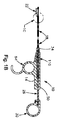
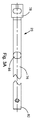
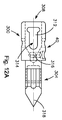
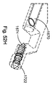
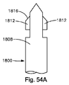
図1A〜図1Cを参照すると、双方向縫合糸通し器具10は、縦方向Lに延び、且つ、近位端P及び遠位端Dを含む。図示のように、器具10は、ハンドル14、ハンドル14に連結された長形本体18、及び長形本体18の遠位端に連結されたブームアーム22を含む。ブームアーム2は、長形本体18の遠位端に連結され、且つ、長形本体18とブームアームハウジング198との間に組織受け取り間隙202を形成するように、ブームアームハウジング198を担持するアーム190を含む。器具10は、アクチュエータ要素26、アクチュエータ要素26の遠位端に連結された針34、及びアクチュエータ要素26の近位端に連結されたグリップ30を更に含む。アクチュエータ要素26及び針34は、ハンドル14の内部及び長形本体18の内部で引込んだ(後方)位置と延長した、すなわち、前進した(前方)位置との間で往復平行移動可能である。器具10は、組織欠損部を通って挿入される縫合糸のストランドを担持するように構成された針状往復要素40及びブームアームハウジング198を更に含む。以下でより詳細に説明するように、往復要素40が針34に連結された時に、往復要素40は、組織を通過することができる。往復要素40が組織欠損部を通過した状態で、往復要素40は、ブームアームハウジング198に取外し可能に連結することができる。   With reference to FIGS. 1A-1C, the bi-directional suture threader 10 extends in the longitudinal direction L and includes a proximal end P and a distal end D. As shown, the instrument 10 includes a handle 14, an elongated body 18 coupled to the handle 14, and a boom arm 22 coupled to the distal end of the elongated body 18. The boom arm 2 is connected to the distal end of the elongated body 18 and carries the boom arm housing 198 so as to form a tissue receiving gap 202 between the elongated body 18 and the boom arm housing 198. 190 is included. The instrument 10 further includes an actuator element 26, a needle 34 coupled to the distal end of the actuator element 26, and a grip 30 coupled to the proximal end of the actuator element 26. Actuator element 26 and needle 34 are reciprocally translatable between a retracted (rear) position and an extended (forward) position within handle 14 and within elongated body 18. The instrument 10 further includes a needle-like reciprocating element 40 and a boom arm housing 198 configured to carry a strand of suture inserted through a tissue defect. As will be described in more detail below, when the reciprocating element 40 is coupled to the needle 34, the reciprocating element 40 can pass through tissue. With the reciprocating element 40 passing through the tissue defect, the reciprocating element 40 can be removably coupled to the boom arm housing 198.

図1A〜図1B及び図2A〜図2Hに示すように、ハンドル14は、本体50の底面から下に延びるグリップ54を有する本体50を含む。本体50は、ほぼ長形かつ形状が矩形である。図2Dに示すように、第1のサイズのボア58は、縦方向Lに沿って本体50の近位端から本体50を通って遠位側に延び、且つ、第2のサイズのボア62内に延びる。第2のボア62は、引き続き、本体50の遠位端を通って延びる第3のサイズのボア66内に遠位側に延びる。各ボア58、62、及び66は、器具10のいくつかの部分を収容するようにサイズ決めされる。例えば、アクチュエータ要素26は、ボア58内で平行移動可能であり、針34は、ボア62内で平行移動可能であり、本体部材18は、ボア66内に固定される。   As shown in FIGS. 1A-1B and 2A-2H, the handle 14 includes a body 50 having a grip 54 that extends downwardly from the bottom surface of the body 50. The main body 50 is substantially long and has a rectangular shape. As shown in FIG. 2D, the first size bore 58 extends along the longitudinal direction L from the proximal end of the body 50 through the body 50 and distally, and within the second size bore 62. Extend to. The second bore 62 continues to extend distally into a third size bore 66 that extends through the distal end of the body 50. Each bore 58, 62, and 66 is sized to accommodate several portions of the instrument 10. For example, the actuator element 26 is translatable within the bore 58, the needle 34 is translatable within the bore 62, and the body member 18 is secured within the bore 66.

図示の実施形態により、図1Bに示すように、第1のボア58は、ほぼ円筒形であり、且つ、アクチュエータ要素26を受け取ることができる。特に、アクチュエータ要素26は、第1のボア58内で往復平行移動可能である。図2D及び図2Hを再び参照すると、第4のボア70は、縦方向Lに対して横に本体50の底面を通って延び、且つ、第1のボア58内に延びる。図示のように、第4のボア70は、直接的に又は間接的に関わらず、アクチュエータ要素26と係合するようになったボールプランジャ74のような嵌合特徴部を収容する。   According to the illustrated embodiment, as shown in FIG. 1B, the first bore 58 is generally cylindrical and can receive the actuator element 26. In particular, the actuator element 26 is reciprocally translatable within the first bore 58. Referring again to FIGS. 2D and 2H, the fourth bore 70 extends through the bottom surface of the body 50 transverse to the longitudinal direction L and extends into the first bore 58. As shown, the fourth bore 70 contains a mating feature such as a ball plunger 74 adapted to engage the actuator element 26, either directly or indirectly.

図3A〜図3Dに示すように、アクチュエータ要素26は、その遠位端に第1の連結要素78、及びその近位端に第2の連結要素82を有する円筒形本体76を含む。アクチュエータ要素26の本体76は、ロックから延びる突起によって係合されるように構成された戻り止め86のような嵌合特徴部を形成する。第1の連結要素78は、針34にアクチュエータ要素26を取り付けるように構成され、第2の連結要素82は、サムリング30にアクチュエータ要素26を取り付けるように構成される。従って、アクチュエータ要素78がユーザにより平行移動される時に、針34は、平行移動される。   As shown in FIGS. 3A-3D, the actuator element 26 includes a cylindrical body 76 having a first coupling element 78 at its distal end and a second coupling element 82 at its proximal end. The body 76 of the actuator element 26 forms a mating feature such as a detent 86 configured to be engaged by a protrusion extending from the lock. The first connecting element 78 is configured to attach the actuator element 26 to the needle 34 and the second connecting element 82 is configured to attach the actuator element 26 to the thumb ring 30. Thus, when the actuator element 78 is translated by the user, the needle 34 is translated.

図4A〜図4Cに示すように、グリップ30は、本体98内に近位側に延びるボア102を有する本体98を含むサムリングとすることができる。ボア102は、アクチュエータ要素26の第2の連結要素82を受け取るようになっている。本体98は、ユーザがサムリング30に力を簡単に印加し、それによってアクチュエータ要素26及び従って針34を前方又は後方に平行移動することができるように、ユーザの親指を受け取ることができるリング106を形成する。   
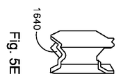
As shown in FIGS. 4A-4C, the grip 30 may be a thumb ring that includes a body 98 having a bore 102 extending proximally within the body 98. The bore 102 is adapted to receive the second coupling element 82 of the actuator element 26. The body 98 includes a ring 106 that can receive the user's thumb so that the user can easily apply a force to the thumb ring 30 and thereby translate the actuator element 26 and thus the needle 34 forward or backward. Form.

アクチュエータ要素26及び針34の移動を制限するために、縫合糸通し具10は、アクチュエータストップ110を含む。図1B及び図5A〜図5Cに示すように、アクチュエータストップ110は、ハンドル14の第2のボア62内に配置されたほぼ円筒形の本体114である。図5A〜図5Cに示すように、アクチュエータストップ110の本体114は、針34を受け取って取り付ける不規則な形状のボア118を含む。不規則な形状は、真円の円筒形を除くあらゆる形状を意味する。   To limit the movement of actuator element 26 and needle 34, suture threader 10 includes an actuator stop 110. As shown in FIGS. 1B and 5A-5C, the actuator stop 110 is a generally cylindrical body 114 disposed within the second bore 62 of the handle 14. As shown in FIGS. 5A-5C, the body 114 of the actuator stop 110 includes an irregularly shaped bore 118 that receives and attaches the needle 34. An irregular shape means any shape except a perfect circular cylinder.

アクチュエータストップ110の本体114は、ハンドル14内に配置することができるボールプランジャのような対応する嵌合特徴部を受け取るその外面に形成された戻り止め122のような2つの嵌合特徴部も形成する。図示のように、戻り止め122は、アクチュエータストップ110の縦軸に対して互いから90°半径方向に分離される。戻り止め122は、針34の回転を必要とする器具10の実施形態に対して、針34の回転を制限又は制御するためにハンドル14内に配置されたボールプランジャ126を受け取るように構成される。従って、針34の回転は、90°に制限される。アクチュエータストップ110は、このような設計に限定されず、他の設計も考えられていることを理解すべきである。例えば、アクチュエータストップ110は、ハンドル14の第2のボア62の狭小化によって具現化することができる。そのような場合、狭小化部分は、ハンドル14に対するアクチュエータ26の所定の平行移動値で針34へのアクチュエータ26の連結の近くでアクチュエータ要素26の遠位端に接触するように構成される。   The body 114 of the actuator stop 110 also forms two mating features such as a detent 122 formed on its outer surface that receives a corresponding mating feature such as a ball plunger that can be disposed within the handle 14. To do. As shown, the detents 122 are separated 90 degrees radially from one another with respect to the longitudinal axis of the actuator stop 110. The detent 122 is configured to receive a ball plunger 126 disposed within the handle 14 to limit or control the rotation of the needle 34 for embodiments of the instrument 10 that require rotation of the needle 34. . Accordingly, the rotation of the needle 34 is limited to 90 °. It should be understood that the actuator stop 110 is not limited to such a design and other designs are contemplated. For example, the actuator stop 110 can be implemented by narrowing the second bore 62 of the handle 14. In such cases, the narrowed portion is configured to contact the distal end of the actuator element 26 near the coupling of the actuator 26 to the needle 34 with a predetermined translation value of the actuator 26 relative to the handle 14.

縫合糸通し具10は、アクチュエータ26及び針34がロックされた時にもはや平行移動することができないように、アクチュエータ26及び従って針34の縦方向位置を固定するように作動可能であるロック130を含むことができる。ロック130は、図6A及び図6Bに示すように、ロッキング要素134、及び図7A及び図7Bに示すように、ロッキング要素134の位置を固定するようにロッキング要素134と相互作用するロッキングキャップ138を含む。図6A及び図6Bを参照すると、ロッキング要素134は、ヘッド142及びヘッド142から延びる本体146を含む。本体146は、2つの大きい戻り止め148、3つの小さい戻り止め150、及び本体146の端部に延びるボア152を形成する。本体は、2つの大きい戻り止め148の間に延びる突起153も形成する。アクチュエータが大きい戻り止め148の1つに受け取られるようにロッキング要素134が位置決めされた時に、ハンドルの第4のボア70内に閉じ込められたボールプランジャ74は、小さい方の外戻り止め150の1つと係合し、アクチュエータ26は、前後に平行移動することができる。しかし、ハンドルの第4のボア70内に閉じ込められたボールプランジャ74が小さい方の中心戻り止め150と係合した時に、ロッキング要素134は、突起153がアクチュエータ26の戻り止め86と係合するように位置決めされ、アクチュエータ26は、移動ができなくなり、その結果、所定の位置にアクチュエータ26及び針34がロックされる。   The suture threader 10 includes a lock 130 that is operable to lock the longitudinal position of the actuator 26 and thus the needle 34 so that the actuator 26 and needle 34 can no longer translate when locked. be able to. The lock 130 includes a locking element 134 as shown in FIGS. 6A and 6B and a locking cap 138 that interacts with the locking element 134 to fix the position of the locking element 134 as shown in FIGS. 7A and 7B. Including. With reference to FIGS. 6A and 6B, the locking element 134 includes a head 142 and a body 146 extending from the head 142. The body 146 forms two large detents 148, three small detents 150, and a bore 152 that extends to the end of the body 146. The body also forms a protrusion 153 that extends between two large detents 148. When the locking element 134 is positioned so that the actuator is received in one of the large detents 148, the ball plunger 74 confined within the handle's fourth bore 70 is in contact with one of the smaller outer detents 150. When engaged, the actuator 26 can translate back and forth. However, when the ball plunger 74 confined within the handle's fourth bore 70 engages the smaller central detent 150, the locking element 134 causes the protrusion 153 to engage the detent 86 of the actuator 26. The actuator 26 cannot move, and as a result, the actuator 26 and the needle 34 are locked at a predetermined position.

ロッキングキャップ138は、ロッキング要素134のボア152と係合するように構成される。図7A及び図7Bに示すように、ロッキングキャップ138は、ヘッド154及びヘッド154から延びる本体156を含む。本体156は、円筒形であり、ロッキング要素134のボア152と係合するように構成される。ロッキングキャップ138の本体156がロッキング要素134のボア152と係合する時にロッキング要素の位置が固定される。   The locking cap 138 is configured to engage the bore 152 of the locking element 134. As shown in FIGS. 7A and 7B, the locking cap 138 includes a head 154 and a body 156 extending from the head 154. The body 156 is cylindrical and is configured to engage the bore 152 of the locking element 134. When the body 156 of the locking cap 138 engages the bore 152 of the locking element 134, the position of the locking element is fixed.

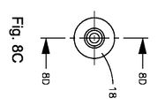
図1A及び図8A〜図8Dに示すように、本体部材18は、縦方向に長形であり、且つ、縦方向に本体部材18の長さ全体を通って延びるチャンネル160を形成する。図1Bに示すように、針34は、本体部材18のチャンネル160内で平行移動可能である。チャンネル160は、第1のチャンネル部分、及び第1のチャンネル部分の遠位側に配置され、且つ、第1のチャンネル部分より大きい直径を有する第2のチャンネル部分164を含む。チャンネル160は、針34が延長した又は前進した(前方)位置と引込んだ(後方)位置との間で往復運動することができるように針34を収容するようなサイズにすることができる。第2のチャンネル部分164は、第1のチャンネル部分より大きい直径を有することが好ましい。針34が後退位置にある時に、より大きい第2のチャンネル部分164は、従って、往復要素40を受け取り、それによって針及び往復要素の鞘として作用することができる。   As shown in FIGS. 1A and 8A-8D, the body member 18 is elongated in the longitudinal direction and forms a channel 160 that extends through the entire length of the body member 18 in the longitudinal direction. As shown in FIG. 1B, the needle 34 can be translated within the channel 160 of the body member 18. The channel 160 includes a first channel portion and a second channel portion 164 disposed distal to the first channel portion and having a larger diameter than the first channel portion. The channel 160 may be sized to accommodate the needle 34 so that the needle 34 can reciprocate between an extended or advanced (forward) position and a retracted (backward) position. The second channel portion 164 preferably has a larger diameter than the first channel portion. When the needle 34 is in the retracted position, the larger second channel portion 164 can thus receive the reciprocating element 40 and thereby act as a sheath for the needle and the reciprocating element.

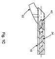
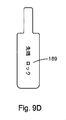
図1A、図8A〜図8B、及び図9A〜図9Dに示すように、本体部材18は、チャンネル160に対してほぼ横の方向に外面を通って延びるアクチュエータスロット168を更に形成する。アクチュエータスロット167は、本体部材18の近位端でチャンネル160の第1のチャンネル区画内に延びる。縫合糸通し器具10は、針34を作動させ、それによって針34に往復要素40を連結又は分離するように構成された先端アクチュエータ180を含む。図1A及び図9A〜図9Dに示すように、先端アクチュエータ180は、アクチュエータスロット168を通って延び、且つ、針34に取り付けられる。特に、先端アクチュエータ180は、先端アクチュエータ180が主針34に回転可能に連結されるように、針34が同様の適合断面を含む位置で針34を受け取る適合ボア188を含む。先端アクチュエータ180は、本体部材18から外へ延びて、ロック位置と非ロック位置の間で器具10の縦軸Lを中心として90°の角度範囲で針34を回転させるようにユーザにより係合させることができる。ロック位置にある時に、往復要素40は、ブームアームハウジング198に連結される。非ロック位置にある時に、往復要素40は、ブームアームハウジング198から離脱される。先端アクチュエータ180は、針先端の位置を示す印189を含む。印は、図9Cに示すように、「先端非ロック」、又は図9Dに示すように「先端ロック」と書くことができる。しかし、器具10の他の実施形態では、往復要素40は、先端アクチュエータ180の回転ではなく、平行移動又は係合特徴部又は他の同様の構造体の作動を通じてブームアームハウジング198に取外し可能に連結することができることを理解すべきである。従って、先端アクチュエータ180は、係合特徴部又は他の同様の構造体の平行移動を可能にするように構成することができることは認められるであろう。   As shown in FIGS. 1A, 8A-8B, and 9A-9D, the body member 18 further defines an actuator slot 168 that extends through the outer surface in a direction generally transverse to the channel 160. Actuator slot 167 extends into the first channel section of channel 160 at the proximal end of body member 18. The suture passer 10 includes a tip actuator 180 configured to actuate the needle 34 and thereby connect or disconnect the reciprocating element 40 to the needle 34. As shown in FIGS. 1A and 9A-9D, the tip actuator 180 extends through the actuator slot 168 and is attached to the needle 34. In particular, the tip actuator 180 includes a matching bore 188 that receives the needle 34 at a location where the needle 34 includes a similar matching cross section such that the tip actuator 180 is rotatably coupled to the main needle 34. The tip actuator 180 extends out of the body member 18 and is engaged by the user to rotate the needle 34 in a 90 ° angular range about the longitudinal axis L of the instrument 10 between a locked position and an unlocked position. be able to. When in the locked position, the reciprocating element 40 is coupled to the boom arm housing 198. When in the unlocked position, the reciprocating element 40 is detached from the boom arm housing 198. The tip actuator 180 includes a mark 189 that indicates the position of the needle tip. The indicia can be written as “tip unlocked” as shown in FIG. 9C or “tip locked” as shown in FIG. 9D. However, in other embodiments of the instrument 10, the reciprocating element 40 is removably coupled to the boom arm housing 198 through translation or engagement feature or other similar structure actuation rather than rotation of the tip actuator 180. It should be understood that it can be done. Thus, it will be appreciated that the tip actuator 180 can be configured to allow translation of an engagement feature or other similar structure.

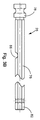
図1A〜図1B及び図10A〜図10Hに示すように、ブームアーム22は、長形本体18から延びる。特に、ブームアーム22は、長形本体部材18の遠位端に連結され、且つ、ブームアームハウジング198に遠位側に延びるアーム190を含む。ブームアームハウジング198は、ブームアーム22の遠位端からほぼ垂直に外へ延び、且つ、往復要素40を受け取るように構成される。従って、ブームアーム22は、ブームアーム22の遠位端に支持されたブームアームハウジング198を含むということができる。組織受け取り間隙202は、ブームアームハウジング198と長形本体18の遠位端の間に配置される。組織受け取り間隙202は、器具10を縫合することによって治療される裂傷のような組織欠損部を有する組織片を受け取るように構成される。   As shown in FIGS. 1A-1B and 10A-10H, the boom arm 22 extends from the elongated body 18. In particular, the boom arm 22 includes an arm 190 that is coupled to the distal end of the elongated body member 18 and extends distally to the boom arm housing 198. Boom arm housing 198 extends substantially vertically out of the distal end of boom arm 22 and is configured to receive reciprocating element 40. Accordingly, it can be said that the boom arm 22 includes a boom arm housing 198 supported at the distal end of the boom arm 22. The tissue receiving gap 202 is disposed between the boom arm housing 198 and the distal end of the elongated body 18. Tissue receiving gap 202 is configured to receive a piece of tissue having a tissue defect such as a laceration that is treated by suturing instrument 10.

ブームアームハウジング198は、本体部材18内に形成されたチャンネル160と整列する円筒形又は他の形状のチャンネル又はボア210を形成する。ブームアームハウジング198は、往復要素40がブームアームハウジング198内で保持される時に、ブームアームハウジング198内で往復要素40を選択的に取外し可能に連結するように構成されたロッキングインタフェース214を含む。図示のように、ロッキングインタフェース214は、ハウジング198にスロット形状の開口部222を形成するハウジング198の内面から延びるフランジ218とすることができる。   The boom arm housing 198 forms a cylindrical or other shaped channel or bore 210 that aligns with a channel 160 formed in the body member 18. Boom arm housing 198 includes a locking interface 214 configured to selectively removably couple reciprocating element 40 within boom arm housing 198 when reciprocating element 40 is retained within boom arm housing 198. As shown, the locking interface 214 can be a flange 218 that extends from the inner surface of the housing 198 that forms a slot-shaped opening 222 in the housing 198.

図11A〜図11Eに示すように、主針34は、長形シャフト230及びシャフト230の遠位端から延びる針要素234を含む。図11A〜図11Bに示すように、シャフト230は、ほぼ円筒形であり、先端アクチュエータ180の適合ボア188に形状が対応する適合部分238を含む。シャフト230の適合部分238は、アクチュエータスロット168と整列している。従って、適合部分238は、アクチュエータストップ110及び先端アクチュエータ180が主針34に連結された位置に配置され、従って、先端アクチュエータ180の適合ボア188を通って延びる。従って、先端アクチュエータ180がユーザにより回転される時に、針34も、上述のように回転することになる。針34は、シャフト230から後方に延びる連結要素242を更に含み、且つ、主針34にアクチュエータ要素26を取り付けるように構成される。連結要素242は、アクチュエータ要素26に対して針34の回転を可能にする六角又はヘッド部分とすることができる。従って、針34は、アクチュエータ要素が固定のままである間に回転させることができる。   As shown in FIGS. 11A-11E, the main needle 34 includes an elongate shaft 230 and a needle element 234 extending from the distal end of the shaft 230. As shown in FIGS. 11A-11B, the shaft 230 is generally cylindrical and includes a matching portion 238 that corresponds in shape to the matching bore 188 of the tip actuator 180. The matching portion 238 of the shaft 230 is aligned with the actuator slot 168. Accordingly, the conforming portion 238 is disposed at a position where the actuator stop 110 and the tip actuator 180 are coupled to the main needle 34 and thus extends through the conforming bore 188 of the tip actuator 180. Therefore, when the tip actuator 180 is rotated by the user, the needle 34 also rotates as described above. Needle 34 further includes a connecting element 242 extending rearwardly from shaft 230 and is configured to attach actuator element 26 to main needle 34. The connecting element 242 can be a hexagon or head portion that allows rotation of the needle 34 relative to the actuator element 26. Thus, the needle 34 can be rotated while the actuator element remains fixed.

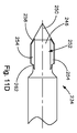
図11D及び図11Eに示すように、針要素234は、針先端250及び円筒形本体246から半径方向に外方に延びる2つのフィン254によって形成された係合特徴部252を有する円筒形本体246を含む。各フィン254は、傾斜前面258及び傾斜後面262を含む。傾斜面258及び262は、フィン254及び従って針要素234を往復要素40とより簡単に係合及びスナップ留めで出し入れすることを可能にする。   As shown in FIGS. 11D and 11E, the needle element 234 has a cylindrical body 246 having an engagement feature 252 formed by a needle tip 250 and two fins 254 extending radially outward from the cylindrical body 246. including. Each fin 254 includes an inclined front surface 258 and an inclined rear surface 262. Inclined surfaces 258 and 262 allow fins 254 and thus needle element 234 to be more easily engaged and snapped into and out of reciprocating element 40.

図12A〜図12Eに示すように、往復要素40は、針係合部分300及び針係合部分300の前方へ延びる組織係合部分304を含む。針係合部分300は、針34の針要素234に連結するように構成される。図示の実施形態により、針係合部分300は、針34の針要素234を受け取るように構成されたボア308を形成する。溝312は、針係合部分300内に形成されて、且つ、ボア308内に延びる。溝312は、針34の係合特徴部252に対応する係合特徴部314形成する。従って、溝312は、針34のフィン254を受け取り、それによって往復要素40に針34を取外し可能に連結するように構成される。溝312の前方には、縫合糸の端部を確実に保持するボア316がある。双方向縫合糸器具10は、往復要素40に固定された縫合糸で予め組み立てることができ、又は器具10には、各々が縫合糸のストランドが固定された状態である複数の往復要素40を設けることができる。   As shown in FIGS. 12A-12E, the reciprocating element 40 includes a needle engaging portion 300 and a tissue engaging portion 304 that extends forward of the needle engaging portion 300. Needle engagement portion 300 is configured to couple to needle element 234 of needle 34. In accordance with the illustrated embodiment, the needle engaging portion 300 forms a bore 308 that is configured to receive the needle element 234 of the needle 34. The groove 312 is formed in the needle engaging portion 300 and extends into the bore 308. The groove 312 forms an engagement feature 314 corresponding to the engagement feature 252 of the needle 34. Accordingly, the groove 312 is configured to receive the fin 254 of the needle 34 and thereby removably couple the needle 34 to the reciprocating element 40. In front of the groove 312 is a bore 316 that securely holds the end of the suture. The bi-directional suture instrument 10 can be pre-assembled with sutures secured to the reciprocating element 40, or the instrument 10 is provided with a plurality of reciprocating elements 40, each with a suture strand secured thereto. be able to.

組織係合部分304は、長方形であり、且つ、ブームアームハウジング198のスロット状開口部222によって受け取られるように成形される。図示のように、組織係合部分304は、針状の先端318及びロッキング機構320を含む。ロッキング機構320は、組織係合部分304内の凹部328を定める突起324である。ロッキング機構320は、ロックしながらブームアームハウジング198内に形成されたロッキングインタフェース214と係合するように構成される。従って、往復要素40は、組織に縫合糸を通し、ハウジング198をブームアーム内でロック及び保持し、しばらく経って組織に縫合糸を再度通すために針に再度取り付けることができる。   Tissue engaging portion 304 is rectangular and is shaped to be received by slotted opening 222 in boom arm housing 198. As shown, the tissue engaging portion 304 includes a needle-like tip 318 and a locking mechanism 320. The locking mechanism 320 is a protrusion 324 that defines a recess 328 in the tissue engaging portion 304. The locking mechanism 320 is configured to engage a locking interface 214 formed in the boom arm housing 198 while locking. Thus, the reciprocating element 40 can pass the suture through the tissue, lock and hold the housing 198 within the boom arm, and reattach the needle to pass the suture through the tissue after some time.

縫合糸ストランドの張りを維持するために、縫合糸器具10は、ハンドル14に連結された縫合糸緊張具350を含むことができる。図1A及び図13に示すように、縫合糸緊張具350は、縫合糸材料の自由端を保持及び固定して縫合糸ストランドの張りを維持するように構成することができ、従って、縫合糸ストランドを張った状態で縫合糸緊張要素350に通すことができる。縫合糸緊張具350は、ハンドル14の両側に縫合糸材料を保持及び固定するように構成され、且つ、ハンドル14を通じて配置することができ、又はハンドル14の両側に1つずつの2つの縫合糸緊張要素350によって実施することができる。緊張具350は、ハンドル14の両側に1つずつの2つのスロットを含み、縫合糸のストランドは、ストランドを張った状態に保持するために2つのスロットの一方に通される。   To maintain the tension of the suture strand, the suture instrument 10 can include a suture tensioner 350 coupled to the handle 14. As shown in FIGS. 1A and 13, the suture tensioner 350 can be configured to hold and secure the free end of the suture material to maintain the tension of the suture strand, and thus the suture strand. And can be passed through the suture tensioning element 350. The suture tensioner 350 is configured to hold and secure suture material on both sides of the handle 14 and can be placed through the handle 14 or two sutures, one on each side of the handle 14. This can be done with the tension element 350. The tendon 350 includes two slots, one on each side of the handle 14, and a strand of suture is passed through one of the two slots to hold the strand in tension.

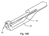
作動において、オペレータは、針のフィン254を往復要素40の溝312内にスナップ留めすることによって針34の上へ縫合糸の取り付けられたストランドを用いて往復要素40を係合させ、任意的に、図14Aに示すように縫合糸緊張具250に縫合糸を通す。オペレータは、次に、人指し指及び中指でハンドル14を把持し、且つ、アクチュエータ26がハンドル14から近位側に引っ込められた位置にある状態で、サムリング30に親指を通す。椎間板の環線維症による亀裂のような組織欠損部を含む組織は、ブームアームハウジング198と本体部材18の間に配置された組織受け取り間隙202内に受け取られる。サムリングロック130がサムリングロッキングキャップ138の作動を通じて開放又は非ロック構成にある状態で、サムリング30は、ハンドル14に対して遠位側に平行移動され、従って、アクチュエータ26及び針34がハンドル14に対して遠位側に前進し、針34の遠位端及びそれに取り付けられた往復要素40、並びに往復要素40に取り付けられた縫合糸が欠損部の近くの組織を通過し、往復要素40とブームアーム22の遠位端が図14Cに示すように強制的に接触される。先端アクチュエータ180がその後に作動されて針34が90°回転し、従って、図14Eに示すように、往復要素40のロッキング機構320がブームのハウジング198のロッキングインタフェース214と係合する。   In operation, the operator engages the reciprocating element 40 with the attached strand of suture onto the needle 34 by snapping the needle fin 254 into the groove 312 of the reciprocating element 40, and optionally 14A, the suture thread is passed through the suture thread tensioner 250. The operator then grips the handle 14 with the forefinger and middle finger and passes the thumb through the thumb ring 30 with the actuator 26 in a position retracted proximally from the handle 14. Tissue including tissue defects such as intervertebral disc fibrosis cracks are received in a tissue receiving gap 202 disposed between the boom arm housing 198 and the body member 18. With the thumb ring lock 130 in an open or unlocked configuration through actuation of the thumb ring locking cap 138, the thumb ring 30 is translated distally relative to the handle 14, so that the actuator 26 and the needle 34 are moved to the handle 14. The distal end of the needle 34 and the reciprocating element 40 attached thereto, and the suture attached to the reciprocating element 40 pass through the tissue near the defect, The distal end of the boom arm 22 is forced into contact as shown in FIG. 14C. The tip actuator 180 is then actuated to rotate the needle 34 by 90 ° so that the locking mechanism 320 of the reciprocating element 40 engages the locking interface 214 of the boom housing 198 as shown in FIG. 14E.

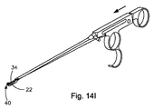
針34が引っ込められた時に、往復要素40は、針34から解放され、且つ、ブームアームハウジング198に選択的に連結されたままになり、その結果、往復要素40及び連結された縫合糸ストランドが欠損部の近くの組織の下側に維持される。針34は、図14Gに示すように、次に、本体部材18によって実施された保護鞘内に引っ込められる。ブームアーム22は、次に、作動され、例えば、針34が安全に保護された状態で、例えば、欠損部の反対の下側上の欠損部の近くの組織の下面上の別の区域まで回転され、最適に移動した状態で、針34は、サムリング30を使用してサムリングロック130及びサムリングロッキングキャップ134を非ロック位置に維持し、ハンドル14に対して再び遠位側に平行移動され、従って、針34は、強制的に上側から欠損部の近くの第2の部位の組織の下側まで通り、針34の遠位端が、図14Kに示すように往復要素40と再係合し、すなわち、再びスナップ留めされる。先端アクチュエータ180は、次に、再作動され、すなわち、先端アクチュエータ198の第1の作動に反対の回転方向に90°回転され、従って、往復要素40がブームのハウジング198から解放される。サムリング30は、次に、ハンドル14に対して近位側に引っ込められ、アクチュエータ26及び針34の対応する引っ込みが発生し、従って、針34の遠位端及び縫合糸を有する往復要素40が、図14Mに示すように、ブームアーム22から離脱し、欠損部の近くの組織の下側から外へ欠損部の近くの組織の上部を通る。これらの段階は、欠損部のサイズ及び組織の特性に基づいて、必要に応じて1回又はそれよりも多くの回数だけ繰り返すことができる。   When the needle 34 is retracted, the reciprocating element 40 is released from the needle 34 and remains selectively connected to the boom arm housing 198 so that the reciprocating element 40 and the connected suture strand are Maintained under the tissue near the defect. The needle 34 is then retracted into the protective sheath implemented by the body member 18, as shown in FIG. 14G. The boom arm 22 is then actuated and rotated, for example, to another area on the lower surface of the tissue near the defect on the lower side opposite the defect, for example, with the needle 34 safely protected. In an optimally moved state, the needle 34 is translated again distally relative to the handle 14 using the thumb ring 30 to maintain the thumb ring lock 130 and thumb ring locking cap 134 in the unlocked position. Thus, the needle 34 is forced from the upper side to the lower side of the tissue at the second site near the defect and the distal end of the needle 34 re-engages with the reciprocating element 40 as shown in FIG. 14K. That is, it is snapped again. The tip actuator 180 is then re-actuated, ie, rotated 90 ° in the direction of rotation opposite to the first actuation of the tip actuator 198, thus releasing the reciprocating element 40 from the boom housing 198. The thumb ring 30 is then retracted proximally relative to the handle 14 and a corresponding retraction of the actuator 26 and needle 34 occurs, so that the reciprocating element 40 having the distal end of the needle 34 and the suture is As shown in FIG. 14M, the boom arm 22 is disengaged and passes through the top of the tissue near the defect from the underside of the tissue near the defect. These steps can be repeated one or more times as needed based on the size of the defect and the tissue characteristics.

別の実施形態ではかつ図15を参照すると、リング状往復要素を使用することができる。図15に示すように、双方向縫合糸通し器具10は、針308の上にスナップ留めされるように構成されたリング状往復要素300を含むことができる。図示のように、針308は、シャフト316から延びる針要素312を含む。針308は、シャフト316の遠位端の周りに形成されたリブ320のような係合特徴部も含む。針要素312及び一部のシャフト316は、往復要素300を通じて少なくとも部分的に往復平行移動を可能にすることができる。シャフト316の周りには、遠位端に傾斜係合面323を有する解放チューブ322が配置される。チューブ322は、チューブ322の傾斜面323が往復要素300に接触することを可能にし、それによって針308からの往復要素300の離脱を補助するためにシャフト316に沿って摺るように構成される。   In another embodiment and with reference to FIG. 15, a ring-like reciprocating element can be used. As shown in FIG. 15, the bi-directional suture threading device 10 can include a ring-shaped reciprocating element 300 configured to snap onto a needle 308. As shown, the needle 308 includes a needle element 312 extending from the shaft 316. Needle 308 also includes engaging features such as ribs 320 formed around the distal end of shaft 316. Needle element 312 and some shafts 316 may allow reciprocal translation at least partially through reciprocating element 300. Around the shaft 316 is disposed a release tube 322 having an inclined engagement surface 323 at the distal end. The tube 322 is configured to slide along the shaft 316 to allow the inclined surface 323 of the tube 322 to contact the reciprocating element 300, thereby assisting in the removal of the reciprocating element 300 from the needle 308.

往復要素300は、本体324を通って延びるボア328を有するリング状の本体324を含む。本体324には、縫合糸ストランド326が取り付けられる。本体324は、針308の係合特徴部に対応する係合特徴部を形成するボア328の内面に形成されたトラフ330を含む。本体324は、直径の拡大を可能にするバネのような特性を有することが好ましい。本体324の直径の拡大により、係合特徴部は、簡単に互いと係合及び離脱することができる。本体324は、本体324の外面に形成されたトラフ342のようなロッキング機構も含む。トラフ342により、往復要素は、図15に示すブームアームハウジング350のようなブームアームのブームアームハウジングに選択的に連結することができる。   The reciprocating element 300 includes a ring-shaped body 324 having a bore 328 extending through the body 324. A suture strand 326 is attached to the body 324. The body 324 includes a trough 330 formed on the inner surface of the bore 328 that forms an engagement feature corresponding to the engagement feature of the needle 308. The body 324 preferably has spring-like characteristics that allow for an increase in diameter. Enlarging the diameter of the body 324 allows the engagement features to easily engage and disengage from each other. The body 324 also includes a locking mechanism such as a trough 342 formed on the outer surface of the body 324. The trough 342 allows the reciprocating element to be selectively coupled to a boom arm housing of a boom arm, such as the boom arm housing 350 shown in FIG.

図示のように、ブームアームハウジング350は、チャンバ358にアクセスをもたらす開口部354を含む。チャンバ358は、テーパ付きであり、且つ、往復要素300及び針308を受け取るように構成される。チャンバ358は、往復要素300上に形成されたロッキング機構338に対応するロッキングインタフェース362を含む。図示のように、ロッキングインタフェース362は、チャンバ358の内面に形成された保持溝内に収容されたバネ荷重式保持ワッシャ366を含む。バネ荷重式ワッシャ366は、往復要素300の本体324内に形成されたトラフ342と係合するように構成される。ブームアームハウジング350からの往復要素300の離脱を補助するために、チャンバ358は、往復要素300が針308と再係合するために外方に跳ねることを可能にするために遠位端の円錐起伏370を含む。   As shown, the boom arm housing 350 includes an opening 354 that provides access to the chamber 358. Chamber 358 is tapered and is configured to receive reciprocating element 300 and needle 308. Chamber 358 includes a locking interface 362 corresponding to a locking mechanism 338 formed on reciprocating element 300. As shown, the locking interface 362 includes a spring loaded retention washer 366 housed in a retention groove formed in the inner surface of the chamber 358. Spring loaded washer 366 is configured to engage trough 342 formed in body 324 of reciprocating element 300. To assist in the removal of the reciprocating element 300 from the boom arm housing 350, the chamber 358 has a distal end cone to allow the reciprocating element 300 to spring outward to re-engage with the needle 308. Includes relief 370.

作動において、針308、往復要素300、外側解放チューブ322、及び縫合糸326は、器具のアクチュエータを作動させることにより、第1の側から第2の側まで組織に通される。往復要素300は、次に、組織の第2の側上でブームアームハウジング350内に受け取られ、往復要素300は、往復要素300上の保持ワッシャ366とロックのためのトラフ342との間のスナップ留めを通じてブームアームハウジング350にロックされ、従って、縫合糸が組織の第2の側に位置決めされる。往復要素300と針308の間のスナップ留めは、針308が僅かに引っ込められる間、外側解放チューブ322で所定の位置に往復要素300を保持することによって解除されることが好ましい。往復要素300と針308の間のスナップ留めが解除されると、針308及び外側解放チューブ322は、更に、縫合糸通し具器具10の本体部材のボアの内側の後退位置に引っ込められ、外側解放チューブ322は、針308に対して本来の位置に更に引っ込められる。ブームアームは、次に、組織の第2の側の別の区域に移動させることができる。位置を直された状態で、針308及び外側解放チューブ322は、作動されて第1の側から第2の側まで組織に通され、針308は、スナップ留めを通じて往復要素300と再係合する。針308、往復要素300、外側解放チューブ322、及び縫合糸326は、次に、完全に引っ込められ、従って、往復要素は、ブームアームハウジング350内のスナップ留め係合から解除され、従って、縫合糸は、第2の組織側から第1の組織側に導入される。   In operation, the needle 308, the reciprocating element 300, the outer release tube 322, and the suture 326 are passed through the tissue from the first side to the second side by actuating the actuator of the instrument. The reciprocating element 300 is then received in the boom arm housing 350 on the second side of the tissue, and the reciprocating element 300 snaps between the retaining washer 366 on the reciprocating element 300 and the trough 342 for locking. Through the clamp, it is locked to the boom arm housing 350 so that the suture is positioned on the second side of the tissue. The snapping between the reciprocating element 300 and the needle 308 is preferably released by holding the reciprocating element 300 in place with the outer release tube 322 while the needle 308 is slightly retracted. When snapping between the reciprocating element 300 and the needle 308 is released, the needle 308 and the outer release tube 322 are further retracted to a retracted position inside the bore of the body member of the suture threader device 10 for outer release. Tube 322 is further retracted to its original position with respect to needle 308. The boom arm can then be moved to another area on the second side of the tissue. In the repositioned state, the needle 308 and the outer release tube 322 are actuated to pass tissue from the first side to the second side, and the needle 308 re-engages with the reciprocating element 300 through snap-fastening. . Needle 308, reciprocating element 300, outer release tube 322, and suture 326 are then fully retracted, so that the reciprocating element is released from the snap-fit engagement in boom arm housing 350, and thus the suture. Is introduced from the second tissue side to the first tissue side.

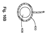
別の実施形態ではかつ図16A及び図16Bを参照すると、往復要素の代わりにワイヤ状縫合糸ループを利用することができる。図16Aに示すように、双方向縫合糸通し器具10は、ブームアームハウジング404のようなブームアームのブームアームハウジング内に捕捉することができる往復要素の代わりに形状記憶特性を有するワイヤ状の縫合糸ループ400を含むことができる。図示のように、縫合糸ループ400は、針408の周りに配置することができる。縫合糸ループ400が針408の周りにある時に針408上に維持することができるように、引張力がループ400に印加される。縫合糸ループ400は、ブームアームハウジング404内に形成された保持溝又はノッチ412内で捕捉かつ保持することができるようにバネ荷重式であることが好ましい。バネ荷重は、ニチノールの介在によって達成することができるなどのワイヤが形状記憶を有する縫合糸の遠位端に接続した結果である。この点に関して、縫合糸ループ及び針は、係合特徴部と考えることができる。   In another embodiment and with reference to FIGS. 16A and 16B, a wire-like suture loop can be utilized in place of the reciprocating element. As shown in FIG. 16A, the bi-directional suture threading device 10 is a wire-like suture having shape memory characteristics instead of a reciprocating element that can be captured in a boom arm housing of a boom arm, such as a boom arm housing 404. A yarn loop 400 may be included. As shown, the suture loop 400 can be placed around the needle 408. A tensile force is applied to the loop 400 so that the suture loop 400 can be maintained on the needle 408 when it is around the needle 408. The suture loop 400 is preferably spring loaded so that it can be captured and held in a retaining groove or notch 412 formed in the boom arm housing 404. Spring loading is the result of a wire connected to the distal end of a suture having shape memory, such as can be achieved by the intervention of nitinol. In this regard, suture loops and needles can be considered engagement features.

別の実施形態ではかつ図17A〜図17Eを参照すると、双方向縫合糸通し器具10は、縫合糸のストランドを捕捉及び担持するように構成された切り欠き454を有する針450を含むことができる。縫合糸による針450は、サムリングを前進させるか、又は単一の作動機構を作動させることにより、第1の側から第2の側まで組織に通される。針450は、ブームアームハウジング460から延びるフィンガ456により偏向され、縫合糸は、次に、組織の第2の側のブームアーム460内に受け取られて捕捉される。針450は、次に、縫合糸が組織の第2の側のままである間に保護鞘内に引っ込められる。縫合糸を再捕捉するために、針450は、ブームアームハウジング460に前進し、次に、回転する。針450が引っ込められた時に、縫合糸は、切り欠き454により再捕捉される。   In another embodiment and with reference to FIGS. 17A-17E, the bi-directional suture threading device 10 can include a needle 450 having a notch 454 configured to capture and carry a strand of suture. . A suture needle 450 is passed through the tissue from the first side to the second side by advancing the thumb ring or actuating a single actuation mechanism. Needle 450 is deflected by fingers 456 extending from boom arm housing 460 and the suture is then received and captured in boom arm 460 on the second side of the tissue. The needle 450 is then retracted into the protective sheath while the suture remains on the second side of the tissue. To recapture the suture, the needle 450 is advanced into the boom arm housing 460 and then rotated. The suture is recaptured by the notch 454 when the needle 450 is retracted.

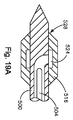
別の実施形態ではかつ図18A及び図18Bを参照すると、双方向縫合糸通し器具10は、針500のチャンネル508内で平行移動可能な針500及び展開可能なワイヤストップ504を含むことができる。図示のように、チャンネル508は、針500の中心部を通って延び、針500の遠位端に近接する開口部512で終端する。展開可能なワイヤストップ504は、図18Bに示すような延長位置と図18Aに示すような後退位置の間でチャンネル508内で平行移動可能である。ワイヤストップ504が延長位置にある時に、ワイヤストップ504は、針500の周りに配置されたチューブ状の往復要素516の前端に対するバットレスをもたらすために開口部512を出て、従って、往復要素516は、ワイヤストップ504と針500の上面上に形成されたバットレス520との間に捕捉される。バットレス520は、針500の周りに完全に延びるリング又は更に単一のビーズとすることができ、又はワイヤストップ504は、図19A及び図19Bに示すように往復要素516のボア528の内面に形成された凹部524に延びることができる。この点に関して、ワイヤストップ504、バットレス520、及び往復要素516の各々は、往復要素516を針500に選択的に連結することを可能にする係合特徴部を形成することができる。往復要素の前側及び後側は、係合特徴部と考えることができることを理解すべきである。   In another embodiment and with reference to FIGS. 18A and 18B, the bi-directional suture threader 10 can include a needle 500 that is translatable within the channel 508 of the needle 500 and a deployable wire stop 504. As shown, channel 508 extends through the center of needle 500 and terminates in an opening 512 proximate the distal end of needle 500. The deployable wire stop 504 is translatable within the channel 508 between an extended position as shown in FIG. 18B and a retracted position as shown in FIG. 18A. When the wire stop 504 is in the extended position, the wire stop 504 exits the opening 512 to provide a buttress against the front end of the tubular reciprocating element 516 disposed around the needle 500, and thus the reciprocating element 516 is , Captured between the wire stop 504 and the buttress 520 formed on the upper surface of the needle 500. The buttress 520 can be a ring or even a single bead that extends completely around the needle 500, or the wire stop 504 can be formed on the inner surface of the bore 528 of the reciprocating element 516 as shown in FIGS. 19A and 19B. Can extend into the recessed portion 524 formed. In this regard, each of the wire stop 504, buttress 520, and reciprocating element 516 can form an engagement feature that allows the reciprocating element 516 to be selectively coupled to the needle 500. It should be understood that the front and rear sides of the reciprocating element can be considered engaging features.

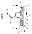
図20A〜図20Dに示すように、往復要素516、針500、及びワイヤストップ504は、ブームアームハウジング540のようなブームアームハウジングへの及びそこからの往復平行移動が可能である。ブームアームハウジング540は、ボア544、及びブームアームハウジング540の開口部に近接するロッキングインタフェース548を含む。ロッキングインタフェース548は、ハウジング540のボア544の内面から延びるエラストマー部材552を含む。エラストマー部材552は、エラストマーの形態を取ることができ、又は正方形、三角形、円筒形、円錐形、長円形などであるがこれらに限定されないOリング形状以外の形状とすることができる。代替的に、ドーナツ型バネをエラストマー部材の代わりに使用することができる。   20A-20D, reciprocating element 516, needle 500, and wire stop 504 are capable of reciprocal translation to and from a boom arm housing, such as boom arm housing 540. The boom arm housing 540 includes a bore 544 and a locking interface 548 proximate the opening of the boom arm housing 540. The locking interface 548 includes an elastomeric member 552 that extends from the inner surface of the bore 544 of the housing 540. Elastomeric member 552 can take the form of an elastomer or can have a shape other than an O-ring shape, including but not limited to square, triangular, cylindrical, conical, oval and the like. Alternatively, a donut spring can be used in place of the elastomeric member.

作動において、針500は、往復要素516の近位端が針500上に形成されたバットレス520と係合する(すなわち、当接する)まで往復要素516のボア528内に平行移動する。ワイヤストップ504は、次に、延長位置に平行移動され、それによってバットレスと係合して往復要素516の遠位端とのバットレスを形成する。針500は、次に、ワイヤストップ504とバットレス520との間に捕捉された往復要素516と共に、組織を通ってブームアームハウジング540内に平行移動させることができる。往復要素516がエラストマー部材552に接触した時に、部材552は、往復要素516がブームアームハウジング540に入ることを可能にするように付勢する。往復要素が完全にハウジング540内にある状態で、エラストマー部材552は、図20Bに示すように、その本来の形態に戻る。   In operation, the needle 500 translates into the bore 528 of the reciprocating element 516 until the proximal end of the reciprocating element 516 engages (ie, abuts) the buttress 520 formed on the needle 500. The wire stop 504 is then translated to the extended position, thereby engaging the buttress and forming a buttress with the distal end of the reciprocating element 516. The needle 500 can then be translated through the tissue and into the boom arm housing 540 with the reciprocating element 516 captured between the wire stop 504 and the buttress 520. When reciprocating element 516 contacts elastomeric member 552, member 552 biases to allow reciprocating element 516 to enter boom arm housing 540. With the reciprocating element completely within the housing 540, the elastomeric member 552 returns to its original form, as shown in FIG. 20B.

ブームアームハウジング540内に往復要素516を保持するために、ワイヤストップ504は、チャンネル508に再び引っ込められ、針500は、ワイヤストップ504と共に引っ込められる。針500が引っ込められると、エラストマー部材552は、図20Dに示すように、往復要素516が針と共に引っ込むのを防止し、それによってブームアームハウジング540内に往復要素516を残す。これらの段階は、欠損部のサイズ及び組織の特性に基づいて、必要に応じて1回又はそれよりも多くの回数だけ繰り返すことができる。展開可能なワイヤストップ504は、針500を出る2つ又はそれよりも多いワイヤを収容することができ、各ワイヤは、0°及び360°の間の角度により半径方向に分離される(図示せず)ことを理解すべきである。更に、展開可能なワイヤストップ504又はストップは、円形、正方形、矩形、三角形、又は当業技術で公知のあらゆる他の形状とすることができる。   To retain the reciprocating element 516 within the boom arm housing 540, the wire stop 504 is retracted back into the channel 508 and the needle 500 is retracted along with the wire stop 504. When the needle 500 is retracted, the elastomeric member 552 prevents the reciprocating element 516 from retracting with the needle, as shown in FIG. 20D, thereby leaving the reciprocating element 516 in the boom arm housing 540. These steps can be repeated one or more times as needed based on the size of the defect and the tissue characteristics. The deployable wire stop 504 can accommodate two or more wires exiting the needle 500, each wire being radially separated by an angle between 0 ° and 360 ° (not shown). )) Should be understood. Further, the deployable wire stop 504 or stop can be circular, square, rectangular, triangular, or any other shape known in the art.

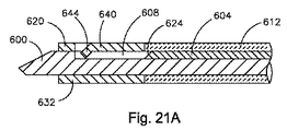
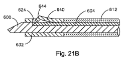
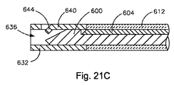
別の実施形態ではかつ図21A〜図21Fを参照すると、針の遠位部分に往復要素を取外し可能に連結するために、展開可能なワイヤストップの代わりに楔を利用することができる。図示のように、双方向縫合糸通し器具10は、針600、針600内に形成されたチャンネル608内で平行移動可能である楔604、及び針600の外面を中心として平行移動可能である離脱チューブ612を含むことができる。針600、楔604、及び離脱チューブ612の近位端は、共に、器具10の本体部材の内部で往復平行移動可能である。   In another embodiment and with reference to FIGS. 21A-21F, a wedge may be utilized in place of a deployable wire stop to removably connect the reciprocating element to the distal portion of the needle. As shown, the bi-directional suture threading device 10 includes a needle 600, a wedge 604 that is translatable within a channel 608 formed in the needle 600, and a release that is translatable about the outer surface of the needle 600. A tube 612 can be included. The proximal end of needle 600, wedge 604, and release tube 612 are both reciprocally translatable within the body member of instrument 10.

図示のように、チャンネル608は、針600の上面に形成され、且つ、針600の実質的な長さに沿って延びる。チャンネル608内に配置された楔604は、チャンネル608内で平行移動可能であり、且つ、針600に取外し可能に連結された往復要素620を解放するように構成された傾斜前面624を含む。   As shown, channel 608 is formed on the upper surface of needle 600 and extends along the substantial length of needle 600. A wedge 604 disposed within the channel 608 includes an inclined front surface 624 that is translatable within the channel 608 and configured to release a reciprocating element 620 removably coupled to the needle 600.

図示のように、往復要素620は、本体632、本体632を通って延びるボア636、及び本体632内に切り込まれた1つ又はそれよりも多くの軸線方向フィンガ640を含む。ボア636は、針600を受け取るように構成される。軸線方向フィンガ640は、偏向可能であり、且つ、往復要素本体632のボア636内に延びる突起644を含む。   As shown, the reciprocating element 620 includes a body 632, a bore 636 extending through the body 632, and one or more axial fingers 640 cut into the body 632. The bore 636 is configured to receive the needle 600. The axial finger 640 is deflectable and includes a protrusion 644 that extends into the bore 636 of the reciprocating element body 632.

作動において、針600は、フィンガ640の突起644が、針600に往復要素620を取外し可能に連結するように針600のチャンネル608内に延びるまで往復要素620のボア636に平行移動する。この点に関して、フィンガ640及びチャンネル608は、往復要素620が針600に選択的に連結することを可能にする係合特徴部であるということができる。離脱チューブ612は、針600が組織を通ってブームアーム内に平行移動される時に往復要素620を押すように往復要素620と係合する。往復要素620を解放するために、楔604は、縁部604の傾斜面624が、図21Bに示すように、往復要素620のフィンガ640に接触して強制的に上げられるまで、チャンネル608内で先端アクチュエータの作動を通じて前方に平行移動される。同時に、先端アクチュエータは、図21Cに示すように、離脱チューブ612を前進させ、それによって針600から往復要素620を押す。楔604及び離脱チューブ612の前進により往復要素620のフィンガ640が持ち上げられ、従って、往復要素620が針600から解放され、往復要素620をブームアームの遠位部分に取外し可能に連結することができる。針600、楔604、及び離脱チューブ612は、次に、往復要素620がブームアームの遠位部分に残っている間に、器具本体によって実施された保護鞘内に引っ込められる。針600に往復要素620を再連結するために、針600は、フィンガ640の突起644が、図21E及び図21Fに示すように、針600のチャンネル608内にもう一度延びるまで往復要素620のボア636内に前進することができる。フィンガ640の突起644が針チャンネル608内に延びる時に、ブームアームの遠位部分から針600と共に往復要素620を引っ込めることができる。   In operation, the needle 600 translates into the bore 636 of the reciprocating element 620 until the projection 644 of the finger 640 extends into the channel 608 of the needle 600 to removably couple the reciprocating element 620 to the needle 600. In this regard, the fingers 640 and the channel 608 can be said to be engagement features that allow the reciprocating element 620 to be selectively coupled to the needle 600. The release tube 612 engages the reciprocating element 620 to push the reciprocating element 620 as the needle 600 is translated through the tissue and into the boom arm. To release the reciprocating element 620, the wedge 604 is moved within the channel 608 until the ramp 624 of the edge 604 is forced up against the finger 640 of the reciprocating element 620, as shown in FIG. 21B. It is translated forward through the operation of the tip actuator. At the same time, the tip actuator advances the detachment tube 612, thereby pushing the reciprocating element 620 from the needle 600, as shown in FIG. 21C. Advancement of the wedge 604 and release tube 612 lifts the finger 640 of the reciprocating element 620 so that the reciprocating element 620 is released from the needle 600 and can be removably connected to the distal portion of the boom arm. . The needle 600, wedge 604, and release tube 612 are then retracted into a protective sheath implemented by the instrument body while the reciprocating element 620 remains in the distal portion of the boom arm. In order to reconnect the reciprocating element 620 to the needle 600, the needle 600 has a bore 636 in the reciprocating element 620 until the protrusion 644 of the finger 640 extends once again into the channel 608 of the needle 600, as shown in FIGS. 21E and 21F. You can move in. When the protrusion 644 of the finger 640 extends into the needle channel 608, the reciprocating element 620 can be retracted along with the needle 600 from the distal portion of the boom arm.

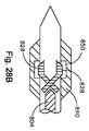
別の実施形態ではかつ図22A及び図22Bを参照すると、針の遠位部分に往復要素を取外し可能に連結するために、展開可能なワイヤストップの代わりに展開可能なボールストップを利用することができる。図22Aに示すように、双方向縫合糸器具10は、針670、針670のチャンネル678内で平行移動可能な楔674、及び楔674の前方へチャンネル678内に配置された展開可能なボールストップ682を含むことができる。図示のように、チャンネル678は、針670の中心部を通って延びて、針670の遠位端の近くに終端する。ボールストップ682の少なくとも一部が選択的にチャンネル678から延びて針670から外へ突出することを可能にする開口部686が、チャンネル678の端部の近くにある。楔674は、その遠位端の傾斜路690を含み、且つ、図22Bに示すような延長位置と図22Aに示すような後退位置の間でチャンネル678内で平行移動可能である。楔674が延長位置にある時に、ボールストップ682は、ボールストップ682の一部が開口部686から延びるように楔674の傾斜路690に乗り、且つ、開口部686を通る。突出ボールストップ682は、針670の周りに配置されたチューブ状の往復要素694の前端に対するバットレスとして作用し、従って、往復要素964は、ボールストップ682と針670の上面上に形成されたバットレス698との間に捕捉される。代替的に、ボールストップ682は、図23A及び図23Bに示すように、往復要素694のボア708内に形成された凹部704内に延びることができる。この点に関して、ボールストップ682、バットレス698、及び往復要素694は、往復要素694を針670に選択的に連結することを可能にする係合特徴部を各々形成することができる。   In another embodiment and with reference to FIGS. 22A and 22B, deployable ball stops may be utilized instead of deployable wire stops to removably couple the reciprocating element to the distal portion of the needle. it can. As shown in FIG. 22A, the bi-directional suture instrument 10 includes a needle 670, a wedge 674 that is translatable within the channel 678 of the needle 670, and a deployable ball stop disposed in the channel 678 forward of the wedge 674. 682 can be included. As shown, channel 678 extends through the center of needle 670 and terminates near the distal end of needle 670. Near the end of the channel 678 is an opening 686 that allows at least a portion of the ball stop 682 to selectively extend from the channel 678 and protrude out of the needle 670. The wedge 674 includes a ramp 690 at its distal end and is translatable within the channel 678 between an extended position as shown in FIG. 22B and a retracted position as shown in FIG. 22A. When the wedge 674 is in the extended position, the ball stop 682 rides on the ramp 690 of the wedge 674 and passes through the opening 686 such that a portion of the ball stop 682 extends from the opening 686. The protruding ball stop 682 acts as a buttress against the front end of a tubular reciprocating element 694 disposed around the needle 670 so that the reciprocating element 964 is a buttress 698 formed on the top surface of the ball stop 682 and the needle 670. Captured between. Alternatively, the ball stop 682 can extend into a recess 704 formed in the bore 708 of the reciprocating element 694 as shown in FIGS. 23A and 23B. In this regard, the ball stop 682, buttress 698, and reciprocating element 694 can each form an engagement feature that allows the reciprocating element 694 to be selectively coupled to the needle 670.

ボールストップ682は、他の構成を含むことができることを理解すべきである。例えば、図24A〜図24Dに示すように、半球状の上部714及び三角形の底部718を有するボールストップ710を利用することができる。図示のように、その遠位端に傾斜路726を有する楔722は、楔が前方に前進するとボールストップ710の三角形の底部718に接触し、それによって半球状の上部714を針の開口部から突出させ、それによってボールストップ半球状上部714と針の表面から延びるバットレス728との間に往復要素を捕捉する。矩形、正方形、三角形、多角形などである他の形状(図示せず)を上述のように半球の代わりにバットレス要素として利用することができることを当業者は認めるべきである。   It should be understood that the ball stop 682 can include other configurations. For example, as shown in FIGS. 24A-24D, a ball stop 710 having a hemispherical top 714 and a triangular bottom 718 can be utilized. As shown, the wedge 722 having a ramp 726 at its distal end contacts the triangular bottom 718 of the ball stop 710 as the wedge advances forward, thereby moving the hemispherical top 714 away from the needle opening. Protrusively captures the reciprocating element between the ball stop hemispherical upper portion 714 and the buttress 728 extending from the needle surface. Those skilled in the art should appreciate that other shapes (not shown) such as rectangles, squares, triangles, polygons, etc. can be utilized as buttress elements instead of hemispheres as described above.

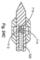
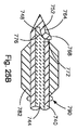
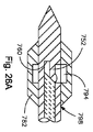
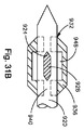
別の実施形態ではかつ図25A及び図25Bを参照すると、針の遠位部分に往復要素を取外し可能に連結するために、展開可能なワイヤストップの代わりに展開可能なフィンガを利用することができる。図25Aに示すように、双方向縫合糸器具10は、針740、針740のチャンネル748内で平行移動可能な楔744、及び楔744の前方へチャンネル748内に配置された展開可能なフィンガストップ752を含むことができる。図示のように、チャンネル748は、針740の中心部を通って延び、針740の遠位端の近くに終端する。フィンガストップ752の少なくとも一部が選択的にチャンネル748から延びて針740から外へ突出することを可能にする開口部756が、チャンネル748の端部の近くにある。フィンガストップ752は、チャンネル748の遠位壁760から延び、且つ、アーム764及びアーム764から延びるヘッド768を含む。図示のように、ヘッド768は、傾斜前面772を含む。楔744は、その遠位端の傾斜路776を含み、且つ、図25Bに示すような延長位置と図25Aに示すような後退位置の間でチャンネル748内で平行移動可能である。楔744が延長位置にある時に、フィンガストップ752の傾斜面772は、フィンガストップ752のヘッド768の一部が開口部756から突出するように楔744の傾斜路776に接触して乗り、且つ、開口部756を通る。突出フィンガストップ752は、針740の周りに配置されたチューブ状の往復要素782の前端に対するバットレスとして作用し、従って、往復要素782は、フィンガストップ752と針740の上面上に形成されたバットレス790との間に捕捉される。代替的に、フィンガストップ752は、図26A及び図26Bに示すように、往復要素782のボア798内に形成された凹部794内に延びることができる。この点に関して、フィンガストップ752、バットレス790、及び往復要素782は、往復要素782を針740に選択的に連結することを可能にする係合特徴部を各々形成することができる。   In another embodiment and with reference to FIGS. 25A and 25B, deployable fingers can be utilized in place of deployable wire stops to removably couple the reciprocating element to the distal portion of the needle. . As shown in FIG. 25A, the bi-directional suture instrument 10 includes a needle 740, a wedge 744 that is translatable within the channel 748 of the needle 740, and a deployable fin gas top disposed in the channel 748 forward of the wedge 744. 752 can be included. As shown, channel 748 extends through the center of needle 740 and terminates near the distal end of needle 740. Near the end of the channel 748 is an opening 756 that allows at least a portion of the fin gas top 752 to selectively extend from the channel 748 and protrude out of the needle 740. Fin gas top 752 extends from distal wall 760 of channel 748 and includes an arm 764 and a head 768 extending from arm 764. As shown, the head 768 includes an inclined front surface 772. Wedge 744 includes a ramp 776 at its distal end and is translatable within channel 748 between an extended position as shown in FIG. 25B and a retracted position as shown in FIG. 25A. When the wedge 744 is in the extended position, the inclined surface 772 of the fin gas top 752 contacts the ramp 776 of the wedge 744 so that a portion of the head 768 of the fin gas top 752 protrudes from the opening 756, and Pass through opening 756. The protruding fin gas top 752 acts as a buttress against the front end of a tubular reciprocating element 782 disposed around the needle 740 so that the reciprocating element 782 is a buttress 790 formed on the upper surface of the fin gas top 752 and the needle 740. Captured between. Alternatively, the fin gas top 752 can extend into a recess 794 formed in the bore 798 of the reciprocating element 782, as shown in FIGS. 26A and 26B. In this regard, the fin gas top 752, buttress 790, and reciprocating element 782 can each form an engagement feature that allows the reciprocating element 782 to be selectively coupled to the needle 740.

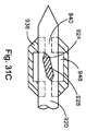
別の実施形態ではかつ図27A及び図27Bを参照すると、針の遠位部分に往復要素を取外し可能に連結するために、展開可能なワイヤストップの代わりに展開可能な鋏フィンガを利用することができる。図27Aに示すように、双方向縫合糸器具10は、針800、針800のチャンネル808内で平行移動可能な楔804、及び楔804の前方へチャンネル808内に配置された展開可能な鋏ストップ812を含むことができる。鋏ストップ812は、ピボット820に関して回転可能である2つのフィンガ816を含む。各フィンガ816は、アーム824、及びアーム824の端部から延びるヘッド828を含む。フィンガ816のアーム824は、ピボット820で交差し、それによってピボット820の後に楔接触空洞832を作成する。図示のように、チャンネル808は、針800の中心部を通って延び、針800の遠位端の近くに終端する。各フィンガ816の少なくとも一部が楔804による作動を通じて選択的にチャンネル808から延びて針800から外へ突出することを可能にする開口部836が、チャンネル808の端部の近くにある。楔804は、三角形形状の端部838を含み、且つ、図27Bに示すような延長位置と図27Aに示すような後退位置の間でチャンネル808内で平行移動可能である。楔804が延長位置にある時に、楔804の成形端部838は、フィンガアーム824によって形成された空洞832に接触し、フィンガ816のヘッド828の一部が各開口部836から突出するまでアーム824をピボット820に関してピボット回転させる。突出ヘッド828は、針800の周りに配置されたチューブ状の往復要素840の前端に対するバットレスとして作用し、従って、鋏ストップ812と針800の表面上に形成されたバットレス844の間に往復要素840が捕捉される。代替的に、鋏ストップ812は、図28A及び図28Bに示すように、往復要素840のボア854内に形成された凹部850内に延びることができる。この点に関して、鋏ストップ812、バットレス844、及び往復要素840は、往復要素840を針800に選択的に連結することを可能にする係合特徴部を各々形成することができる。   In another embodiment and with reference to FIGS. 27A and 27B, deployable scissor fingers may be utilized in place of deployable wire stops to removably couple the reciprocating element to the distal portion of the needle. it can. As shown in FIG. 27A, the bi-directional suture instrument 10 includes a needle 800, a wedge 804 that is translatable within the channel 808 of the needle 800, and a deployable heel stop that is disposed in the channel 808 forward of the wedge 804. 812 may be included. The heel stop 812 includes two fingers 816 that are rotatable with respect to the pivot 820. Each finger 816 includes an arm 824 and a head 828 extending from the end of arm 824. The arms 824 of the fingers 816 intersect at a pivot 820, thereby creating a wedge contact cavity 832 after the pivot 820. As shown, channel 808 extends through the center of needle 800 and terminates near the distal end of needle 800. Near the end of the channel 808 is an opening 836 that allows at least a portion of each finger 816 to selectively extend from the channel 808 and project out of the needle 800 through actuation by the wedge 804. The wedge 804 includes a triangular end 838 and is translatable within the channel 808 between an extended position as shown in FIG. 27B and a retracted position as shown in FIG. 27A. When the wedge 804 is in the extended position, the shaped end 838 of the wedge 804 contacts the cavity 832 formed by the finger arm 824 and the arm 824 until a portion of the head 828 of the finger 816 protrudes from each opening 836. Pivot about pivot 820. The protruding head 828 acts as a buttress against the front end of a tubular reciprocating element 840 disposed around the needle 800, and thus the reciprocating element 840 between the heel stop 812 and the buttress 844 formed on the surface of the needle 800. Is captured. Alternatively, the heel stop 812 can extend into a recess 850 formed in the bore 854 of the reciprocating element 840, as shown in FIGS. 28A and 28B. In this regard, the heel stop 812, buttress 844, and reciprocating element 840 can each form an engagement feature that allows the reciprocating element 840 to be selectively coupled to the needle 800.

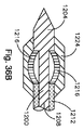
別の実施形態ではかつ図29A及び図29Bを参照すると、針の遠位部分に往復要素を取外し可能に連結するために、展開可能なワイヤストップの代わりに展開可能な回転ブーツを利用することができる。図29Aに示すように、双方向縫合糸器具10は、針860、針860のチャンネル868内で平行移動可能な楔864、及び楔864の前方へチャンネル868内に配置された展開可能なブーツストップ872を含むことができる。ブーツストップ872は、ピボット876を中心としてピボット回転可能であり、且つ、脚882から延びるヘッド部分880を含む。図示のように、脚は、空洞883を形成する。図示のように、チャンネル868は、針860の中心部を通って延び、針860の遠位端の近くに終端する。ブーツストップ872のヘッド880の少なくとも一部が楔864による作動を通じてチャンネル868から選択的に延びて針860から外へ突出することを可能にする開口部884が、チャンネル868の端部の近くにある。楔864は、三角形形状の端部886を含み、且つ、図29Bに示すような延長位置と図29Aに示すような後退位置の間でチャンネル868内で平行移動可能である。楔864が延長位置にある時に、楔864の成形端部886は、ブーツ脚882によって形成された空洞883に接触し、ブーツストップ872のヘッド880の一部が開口部884から突出するまでブーツストップ872をピボット876を中心としてピボット回転させる。突出ヘッド880は、針860の周りに配置されたチューブ状の往復要素890の前端に対するバットレスとして作用し、従って、往復要素890は、ブーツストップ872と針860の表面上に形成されたバットレス894の間に捕捉される。代替的に、ブーツストップ872は、図230A及び図30Bに示すように、往復要素890のボア798内に形成された凹部898内に延びることができる。この点に関して、ブーツストップ872、バットレス894、及び往復要素890は、往復要素890を針860に選択的に連結することを可能にする係合特徴部を各々形成することができる。   In another embodiment and with reference to FIGS. 29A and 29B, deployable rotatable boots may be utilized instead of deployable wire stops to removably couple the reciprocating element to the distal portion of the needle. it can. As shown in FIG. 29A, the bi-directional suture instrument 10 includes a needle 860, a wedge 864 that is translatable within the channel 868 of the needle 860, and a deployable boot stop disposed in the channel 868 forward of the wedge 864. 872 can be included. Boot stop 872 is pivotable about pivot 876 and includes a head portion 880 extending from leg 882. As shown, the legs form a cavity 883. As shown, channel 868 extends through the center of needle 860 and terminates near the distal end of needle 860. Near the end of the channel 868 is an opening 884 that allows at least a portion of the head 880 of the boot stop 872 to selectively extend from the channel 868 and project out of the needle 860 through actuation by the wedge 864. . The wedge 864 includes a triangular end 886 and is translatable within the channel 868 between an extended position as shown in FIG. 29B and a retracted position as shown in FIG. 29A. When the wedge 864 is in the extended position, the molded end 886 of the wedge 864 contacts the cavity 883 formed by the boot leg 882 and the boot stop until a portion of the head 880 of the boot stop 872 protrudes from the opening 884. 872 is pivoted about pivot 876. The protruding head 880 acts as a buttress against the front end of a tubular reciprocating element 890 disposed around the needle 860, so that the reciprocating element 890 is a boot stop 872 and a buttress 894 formed on the surface of the needle 860. Captured in between. Alternatively, the boot stop 872 can extend into a recess 898 formed in the bore 798 of the reciprocating element 890, as shown in FIGS. 230A and 30B. In this regard, the boot stop 872, buttress 894, and reciprocating element 890 can each form an engagement feature that allows the reciprocating element 890 to be selectively coupled to the needle 860.

別の実施形態ではかつ図31A〜図31Cを参照すると、針の遠位部分に往復要素を取外し可能に連結するために、展開可能なワイヤストップの代わりに展開可能な回転ウイングを利用することができる。図31Aに示すように、双方向縫合糸器具10は、針920の外面に回転可能に連結された2つのウイング924を有する針920を含むことができる。回転ウイング924は、ピン928で針920に連結される。1つ又はそれよりも多くのワイヤが、回転ウイング924に取り付けられ、これは、作動機構にウイング924を連結する。図示のように、針920は、往復要素936のボア932と係合する。往復要素936は、往復要素936を通って延びて針920のウイング924と整列する軸線方向スロット940を含む。従って、ウイング924が整列された位置にある時に、図31A〜図31Bに示すように、ウイング924は、スロット940を通り、且つ、往復要素のボア932内に通ることができる。図示のように、溝又は凹部948は、ボア932の内面に形成される。凹部940は、ほぼボア932の中心にあり、且つ、回転するとウイング924によって係合されるように構成される。   In another embodiment and with reference to FIGS. 31A-31C, deploying a deployable rotating wing instead of a deployable wire stop to removably couple the reciprocating element to the distal portion of the needle. it can. As shown in FIG. 31A, the bi-directional suture instrument 10 can include a needle 920 having two wings 924 rotatably coupled to the outer surface of the needle 920. The rotating wing 924 is connected to the needle 920 with a pin 928. One or more wires are attached to the rotating wing 924, which couples the wing 924 to the actuation mechanism. As shown, the needle 920 engages the bore 932 of the reciprocating element 936. The reciprocating element 936 includes an axial slot 940 that extends through the reciprocating element 936 and aligns with the wing 924 of the needle 920. Thus, when the wing 924 is in the aligned position, the wing 924 can pass through the slot 940 and into the bore 932 of the reciprocating element, as shown in FIGS. 31A-31B. As shown, a groove or recess 948 is formed in the inner surface of the bore 932. Recess 940 is approximately in the center of bore 932 and is configured to be engaged by wing 924 when rotated.

作動において、ワイヤが前進した時に、ウイング924は、ピン928に関して回転し、ウイング924の端部は、往復要素936の凹部948内に延び、従って、往復要素936は、図31Cに示すように針920に連結する。この点に関して、ウイング924及び往復要素936は、往復要素936を針920に選択的に連結することを可能にする係合特徴部を各々形成することができる。   In operation, as the wire is advanced, the wing 924 rotates with respect to the pin 928 and the end of the wing 924 extends into the recess 948 of the reciprocating element 936 so that the reciprocating element 936 is a needle as shown in FIG. 31C. Connect to 920. In this regard, the wing 924 and the reciprocating element 936 can each form an engagement feature that allows the reciprocating element 936 to be selectively coupled to the needle 920.

別の実施形態ではかつ図32A及び図32Bを参照すると、針の遠位部分に往復要素を取外し可能に連結するために、展開可能なワイヤストップの代わりに拡張可能な針ヘッドを利用することができる。図32Aに示すように、双方向縫合糸器具10は、シャフト956に連結された拡張可能なヘッド954及び針950のシャフト956の周りに配置されたスリーブ状の楔958を有する針950を含むことができる。針950の拡張可能なヘッド954は、針ヘッド954の近位端内に切り込まれた2つ又はそれよりも多いスロット962を有し、これは、針ヘッド954が付勢された時に拡張することを可能にする。針950のシャフト956又はスリーブ状の楔958は、針950又はスリーブ状の楔958が他方に対して平行移動することを可能にする作動機構に連結することができる。   In another embodiment and with reference to FIGS. 32A and 32B, an expandable needle head may be utilized instead of a deployable wire stop to removably couple the reciprocating element to the distal portion of the needle. it can. As shown in FIG. 32A, the bi-directional suture instrument 10 includes a needle 950 having an expandable head 954 coupled to a shaft 956 and a sleeve-like wedge 958 disposed about the shaft 956 of the needle 950. Can do. The expandable head 954 of the needle 950 has two or more slots 962 cut into the proximal end of the needle head 954 that expands when the needle head 954 is biased. Make it possible. The shaft 956 or sleeve-like wedge 958 of the needle 950 can be coupled to an actuation mechanism that allows the needle 950 or sleeve-like wedge 958 to translate relative to the other.

作動において、針950は、ヘッド954が図32Aに示すように非拡張状態である時に、往復要素970のボア966に通して前進させることができる。ヘッド954がボア966を通った状態で、スリーブ状の楔958は、シャフト956に沿って拡張可能な針ヘッド954のスロット962内に平行移動させることができ、従って、針ヘッド954が拡張され、図32Bに示すように、拡張可能な針ヘッド954の近位端と共に往復要素970の遠位端に対するバットレスがもたらされる。代替的に、針ヘッド954は、往復要素970のボア内に形成された凹部の中に延びることができる。この点に関して、針ヘッド954及び往復要素970は、往復要素970を針950に選択的に連結することを可能にする係合特徴部を各々形成することができる。   In operation, the needle 950 can be advanced through the bore 966 of the reciprocating element 970 when the head 954 is in an unexpanded state as shown in FIG. 32A. With the head 954 passing through the bore 966, the sleeve-like wedge 958 can be translated along the shaft 956 into the slot 962 of the expandable needle head 954 so that the needle head 954 is expanded, As shown in FIG. 32B, a buttress is provided for the distal end of the reciprocating element 970 along with the proximal end of the expandable needle head 954. Alternatively, the needle head 954 can extend into a recess formed in the bore of the reciprocating element 970. In this regard, the needle head 954 and the reciprocating element 970 can each form an engagement feature that allows the reciprocating element 970 to be selectively coupled to the needle 950.

別の実施形態ではかつ図33A及び図33Bを参照すると、針の遠位部分に往復要素を取外し可能に連結するために、展開可能なワイヤストップの代わりに拡張可能なスリーブを利用することができる。図33Aに示すように、双方向縫合糸器具10は、シャフト998から延びるヘッド994及び針990のシャフト998の周りに配置されたスリーブ1002を有する針990を含むことができる。図示のように、ヘッド994の近位側は、スリーブ1002と相互作用する面取り面1006を含む。スリーブ1002の遠位端は、前方に付勢された時に偏向することができる偏向可能アーム1010を形成する軸線方向スリットを有する。各アーム1010は、半径方向に外方に延びる突起1014を含む。シャフト998又はスリーブ1002は、作動機構に連結し、それによってシャフト998又はスリーブ1002が他方に対して平行移動することを可能にすることができる。   In another embodiment and with reference to FIGS. 33A and 33B, an expandable sleeve can be utilized instead of a deployable wire stop to removably couple the reciprocating element to the distal portion of the needle. . As shown in FIG. 33A, the bi-directional suture instrument 10 can include a needle 990 having a head 994 extending from the shaft 998 and a sleeve 1002 disposed about the shaft 998 of the needle 990. As shown, the proximal side of head 994 includes a chamfered surface 1006 that interacts with sleeve 1002. The distal end of the sleeve 1002 has an axial slit that forms a deflectable arm 1010 that can deflect when biased forward. Each arm 1010 includes a protrusion 1014 extending radially outward. Shaft 998 or sleeve 1002 may be coupled to an actuation mechanism, thereby allowing shaft 998 or sleeve 1002 to translate relative to the other.

作動において、針990は、図33Aに示すように、往復要素1024のボア1020に通して前進させることができる。針990のヘッド994が適切にボア1020内に置かれた状態で、図33Bに示すように、スリーブ1002は、シャフト998に沿って平行移動され、それによって図33Bに示すようにスリーブ1002の偏向可能アーム1010を面取り面1006に乗せることができる。アーム1010が偏向した時に、アーム1010の突起1014は、ボア1020の内面に形成された凹部1030に延び、従って、往復要素1024は、針990に連結される。この点に関して、偏向可能アーム1010及び往復要素1024は、往復要素1024を針990に選択的に連結することを可能にする係合特徴部を各々形成することができる。しかし、アーム1010の突起1014は、往復要素1024の遠位端に対するバットレス形成するように延びることができることを理解すべきである。   In operation, the needle 990 can be advanced through the bore 1020 of the reciprocating element 1024 as shown in FIG. 33A. With the head 994 of the needle 990 properly positioned within the bore 1020, the sleeve 1002 is translated along the shaft 998, as shown in FIG. 33B, thereby deflecting the sleeve 1002 as shown in FIG. 33B. The possible arm 1010 can be placed on the chamfered surface 1006. When the arm 1010 is deflected, the projection 1014 of the arm 1010 extends into a recess 1030 formed in the inner surface of the bore 1020 so that the reciprocating element 1024 is coupled to the needle 990. In this regard, the deflectable arm 1010 and the reciprocating element 1024 can each form an engagement feature that allows the reciprocating element 1024 to be selectively coupled to the needle 990. However, it should be understood that the protrusion 1014 of the arm 1010 can extend to form a buttress against the distal end of the reciprocating element 1024.

別の実施形態ではかつ図34A〜図34Dを参照すると、スリーブは、針に形成された逃げ溝からスリーブを引っ込めることによって拡張可能にすることができる。図34Aに示すように、双方向縫合糸器具10は、シャフト1058から延びるヘッド1054及び針1050のシャフト1058の周りに配置されたスリーブ1062を有する針1050を含むことができる。図示のように、シャフト1058は、ヘッド1054の近位端と共に逃げ溝1070を作成するその遠位端のテーパ1066を含む。スリーブ1062は、図34Aに示すように、針1050内に形成された逃げ溝1070と係合するように構成されたヘッド1080を形成するために遠位端のテーパ1078を有するボア1074を含む。シャフト1058又はスリーブ1062は、作動機構に連結し、それによってシャフト10588又はスリーブ1062が他方に対して平行移動することを可能にすることができる。   In another embodiment and with reference to FIGS. 34A-34D, the sleeve can be made expandable by retracting the sleeve from a relief groove formed in the needle. As shown in FIG. 34A, the bi-directional suture instrument 10 can include a needle 1050 having a head 1054 extending from the shaft 1058 and a sleeve 1062 disposed about the shaft 1058 of the needle 1050. As shown, the shaft 1058 includes a taper 1066 at its distal end that creates a relief groove 1070 with the proximal end of the head 1054. The sleeve 1062 includes a bore 1074 having a distal end taper 1078 to form a head 1080 configured to engage a relief groove 1070 formed in the needle 1050, as shown in FIG. 34A. Shaft 1058 or sleeve 1062 can be coupled to an actuation mechanism, thereby allowing shaft 10588 or sleeve 1062 to translate relative to the other.

作動において、針1050は、図34Aに示すように、往復要素1086のボア1082に通して前進させることができる。針1050のヘッド1054が適切にボア1082に置かれた状態で、スリーブ1062は、シャフト1058に沿って後方に平行移動され、スリーブ1062のヘッド1080を逃げ溝1070から離脱することができ、それによってスリーブ1062のヘッド1082は、図34Bに示すように、シャフト1058に乗る。スリーブ1062が引っ込められた時に、スリーブ1062のヘッド1082は、ボア1082の内面に形成された凹部1090内に延び、従って、往復要素1086は、針1050に連結される。この点に関して、スリーブ1062及び往復要素1086は、往復要素1086を針1050に選択的に連結することを可能にする係合特徴部を各々形成することができる。しかし、スリーブ1062のヘッド1082は、往復要素1086の遠位端に対するバットレスを形成するように延びることができることを理解すべきである。   In operation, the needle 1050 can be advanced through the bore 1082 of the reciprocating element 1086 as shown in FIG. 34A. With the head 1054 of the needle 1050 properly placed in the bore 1082, the sleeve 1062 can be translated back along the shaft 1058 to disengage the head 1080 of the sleeve 1062 from the escape groove 1070, thereby The head 1082 of the sleeve 1062 rides on the shaft 1058 as shown in FIG. 34B. When the sleeve 1062 is retracted, the head 1082 of the sleeve 1062 extends into a recess 1090 formed in the inner surface of the bore 1082 so that the reciprocating element 1086 is coupled to the needle 1050. In this regard, the sleeve 1062 and the reciprocating element 1086 can each form an engagement feature that allows the reciprocating element 1086 to be selectively coupled to the needle 1050. However, it should be understood that the head 1082 of the sleeve 1062 can extend to form a buttress with respect to the distal end of the reciprocating element 1086.

図34A及び図34Bに示すように、スリーブ1062のヘッド1080は、往復要素1086の凹部1090と係合するピーク1098を含むことができる。図34Aに示すように、スリーブ1062のヘッド1080が逃げ溝1070と接続している時に、針1050のヘッド1054の外面は、スリーブ1062の外面に整列する。代替的に、スリーブ1062のヘッド1080は、図34C及び図34Dに示すように、往復要素1086の凹部1090と係合する突起1102を含むことができる。上述の拡張可能スリーブの実施形態のいずれにおいても、拡張可能スリーブは、1つ又はそれよりも多くの歯のような付加的なバットレス特徴部を有することができる。当業者は、付加的なバットレス特徴部が好ましくは矩形であるが、平坦、円形、三角形、又は当業技術において現在公知であるあらゆる他の形状とすることができることを認めるであろう。上述の実施形態の付加的な修正において、あらゆる付加的なバットレス特徴部を含む拡張可能スリーブの遠位先端は、代わりに往復要素に遠位の地点で展開することができる。   As shown in FIGS. 34A and 34B, the head 1080 of the sleeve 1062 can include a peak 1098 that engages the recess 1090 of the reciprocating element 1086. As shown in FIG. 34A, the outer surface of the head 1054 of the needle 1050 is aligned with the outer surface of the sleeve 1062 when the head 1080 of the sleeve 1062 is connected to the relief groove 1070. Alternatively, the head 1080 of the sleeve 1062 can include a protrusion 1102 that engages the recess 1090 of the reciprocating element 1086 as shown in FIGS. 34C and 34D. In any of the above-described expandable sleeve embodiments, the expandable sleeve can have additional buttress features such as one or more teeth. One skilled in the art will appreciate that the additional buttress features are preferably rectangular, but can be flat, circular, triangular, or any other shape currently known in the art. In additional modifications of the above-described embodiments, the distal tip of the expandable sleeve, including any additional buttress features, can instead be deployed at a point distal to the reciprocating element.

別の実施形態ではかつ図35A及び図5Bを参照すると、針の遠位部分に往復要素を取外し可能に連結するために、展開可能なワイヤストップの代わりに拡張可能な分割リングストップを利用することができる。図35Aに示すように、双方向縫合糸器具10は、シャフト1118から延びるヘッド1114と、シャフト1118の周りに配置されたスリーブ1122と、スリーブ1122とヘッド1114の間にシャフト1118の周りに配置された分割リングストップ1126とを有する針1110を含むことができる。ヘッド1114の近位側は、面取り面1132を有し、スリーブ1122の遠位端は、分割リング1126の対応する面取り面1140と各々接続する面取り面1136を有する。シャフト1118又はスリーブ1122は、作動機構に連結し、それによってシャフト11188又はスリーブ1122が他方に対して平行移動することを可能にすることができる。   In another embodiment and with reference to FIGS. 35A and 5B, utilizing an expandable split ring stop instead of a deployable wire stop to removably couple the reciprocating element to the distal portion of the needle. Can do. As shown in FIG. 35A, the bi-directional suture instrument 10 is disposed about the shaft 1118 between the head 1114 extending from the shaft 1118, a sleeve 1122 disposed about the shaft 1118, and between the sleeve 1122 and the head 1114. A needle 1110 having a split ring stop 1126 may be included. The proximal side of the head 1114 has a chamfered surface 1132 and the distal end of the sleeve 1122 has a chamfered surface 1136 that each connects with a corresponding chamfered surface 1140 of the split ring 1126. Shaft 1118 or sleeve 1122 may be coupled to an actuation mechanism, thereby allowing shaft 11188 or sleeve 1122 to translate relative to the other.

作動において、針1110は、図35Aに示すように、往復要素1144のボア1142に通して前進させることができる。針1050のヘッド1054が適切にボア1082に置かれた状態で、スリーブ1122は、シャフト1118に沿って前方に平行移動させることができ、又は針1110は、スリーブ1122内で後方に平行移動させることができ、分割リングストップ1126は、針ヘッド1114に対して押し付けられる。スリーブ1122が更に前方に平行移動されると、スリーブ1122の面取り面1136及び針ヘッド1114の面取り面1132は、分割リングストップ1126の対応する面取り面1140と係合し、分割リング1126をボア1142の内面に形成された凹部1160内に押し込み、図35Bに示すように、それによって針に往復要素を取外し可能に連結する。この点に関して、分割リングストップ1126及び往復要素1144は、往復要素1144を針1110に選択的に連結することを可能にする係合特徴部を各々形成することができる。分割リング1126の縁部は、1つ又はそれよりも多くの歯のような付加的なバットレス特徴部を有することができることを理解すべきである。当業者は、付加的なバットレス特徴部が好ましくは矩形であるが、平坦、円形、三角形、又は当業技術において現在公知であるあらゆる他の形状とすることができることを認めるであろう。   In operation, the needle 1110 can be advanced through the bore 1142 of the reciprocating element 1144, as shown in FIG. 35A. With the head 1054 of the needle 1050 properly placed in the bore 1082, the sleeve 1122 can be translated forward along the shaft 1118, or the needle 1110 can be translated backward within the sleeve 1122. The split ring stop 1126 is pressed against the needle head 1114. As the sleeve 1122 is translated further forward, the chamfered surface 1136 of the sleeve 1122 and the chamfered surface 1132 of the needle head 1114 engage the corresponding chamfered surface 1140 of the split ring stop 1126, causing the split ring 1126 to engage the bore 1142. It is pushed into a recess 1160 formed in the inner surface, thereby removably connecting the reciprocating element to the needle, as shown in FIG. 35B. In this regard, the split ring stop 1126 and the reciprocating element 1144 can each form an engagement feature that allows the reciprocating element 1144 to be selectively coupled to the needle 1110. It should be understood that the edge of the split ring 1126 can have additional buttress features such as one or more teeth. One skilled in the art will appreciate that the additional buttress features are preferably rectangular, but can be flat, circular, triangular, or any other shape currently known in the art.

別の実施形態ではかつ図36A及び図36Bを参照すると、針の遠位部分に往復要素を取外し可能に連結するために、展開可能なワイヤストップの代わりに拡張可能なケージを利用することができる。図36Aに示すように、双方向縫合糸器具10は、シャフト1208から延びるヘッド1204と、針1200のシャフト1208の周りに配置されたスリーブ1212と、針ヘッド1204とスリーブ1212の間にシャフト1208の周りに配置された拡張可能ケージ1216とを有する針1200を含むことができる。拡張可能ケージ1216は、チューブ状であり、且つ、拡張可能ケージ1216の近位端及び遠位端が材料の中実リングであるように、チューブの縦軸に沿って切り込まれた2つ又はそれよりも多い閉じ込められた軸線方向スロットを有する。シャフト1208又はスリーブ1212は、作動機構に連結し、それによってシャフト12088又はスリーブ1212が他方に対して平行移動することを可能にすることができる。   In another embodiment and with reference to FIGS. 36A and 36B, an expandable cage can be utilized instead of a deployable wire stop to removably couple the reciprocating element to the distal portion of the needle. . As shown in FIG. 36A, the bi-directional suture instrument 10 includes a head 1204 extending from the shaft 1208, a sleeve 1212 disposed around the shaft 1208 of the needle 1200, and a shaft 1208 between the needle head 1204 and the sleeve 1212. A needle 1200 having an expandable cage 1216 disposed therearound can be included. The expandable cage 1216 is tube-shaped and two or two cut along the longitudinal axis of the tube so that the proximal and distal ends of the expandable cage 1216 are solid rings of material. It has more confined axial slots. Shaft 1208 or sleeve 1212 may be coupled to an actuation mechanism, thereby allowing shaft 12088 or sleeve 1212 to translate relative to the other.

作動において、針1200は、図36Aに示すように、往復要素1224のボア1220に通して前進させることができる。針1200のヘッド1204が適切にボア1220に置かれた状態で、スリーブ1212は、シャフト1208に沿って前方に平行移動され、針ヘッド1204とスリーブ1212の間に拡張可能ケージ1216を圧縮することができ、従って、拡張可能ケージ1216は、図36Bに示すように、強制的に半径方向に外方に押され、且つ、往復要素1224のボア1220内に形成された凹部1232内に延びる。拡張ケージ1216は、針1200に往復要素1224を連結する。代替的に、針1200は、スリーブ1212内で引っ込めてケージ1216を半径方向に拡張することができ、従って、往復要素1224は、針1200に連結される。この点に関して、拡張可能ケージ1216及び往復要素1224は、往復要素1224を針1200に選択的に連結することを可能にする係合特徴部を各々形成することができる。   In operation, the needle 1200 can be advanced through the bore 1220 of the reciprocating element 1224 as shown in FIG. 36A. With the head 1204 of the needle 1200 properly positioned in the bore 1220, the sleeve 1212 can be translated forward along the shaft 1208 to compress the expandable cage 1216 between the needle head 1204 and the sleeve 1212. Thus, the expandable cage 1216 is forced radially outwardly and extends into a recess 1232 formed in the bore 1220 of the reciprocating element 1224, as shown in FIG. 36B. Expansion cage 1216 couples reciprocating element 1224 to needle 1200. Alternatively, the needle 1200 can be retracted within the sleeve 1212 to radially expand the cage 1216 so that the reciprocating element 1224 is coupled to the needle 1200. In this regard, the expandable cage 1216 and the reciprocating element 1224 can each form an engagement feature that allows the reciprocating element 1224 to be selectively coupled to the needle 1200.

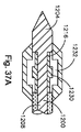
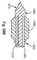
拡張可能ケージは、付加的なバットレス特徴部及び構成を有することができる。例えば、拡張可能ケージ1216は、図37A及び図37Bに示すように、往復要素の凹部と係合する突起1233を含むことができる。当業者は、付加的なバットレス特徴部が好ましくは矩形であるが、平坦、円形、三角形、又は当業技術において現在公知であるあらゆる他の形状とすることができることを認めるであろう。更に、拡張可能ケージ1216は、図38A及び図38Bに示すように、往復要素の凹部内に展開することができる拡張可能な部分1234を含むことができる。図示のように、拡張可能な部分1234は、ケージ1216の中心の近くに形成される。拡張可能な部分1234は、ケージ1216が圧縮された時に、半径方向に外方に突出するケージ1216の一部分である。   The expandable cage can have additional buttress features and configurations. For example, the expandable cage 1216 can include a protrusion 1233 that engages a recess in the reciprocating element, as shown in FIGS. 37A and 37B. One skilled in the art will appreciate that the additional buttress features are preferably rectangular, but can be flat, circular, triangular, or any other shape currently known in the art. Further, the expandable cage 1216 can include an expandable portion 1234 that can be deployed in a recess in the reciprocating element, as shown in FIGS. 38A and 38B. As shown, the expandable portion 1234 is formed near the center of the cage 1216. The expandable portion 1234 is the portion of the cage 1216 that protrudes radially outward when the cage 1216 is compressed.

別の実施形態ではかつ図39A及び図39Bを参照すると、針の遠位部分に往復要素を取外し可能に連結するために、展開可能な回転楕円形針先端を利用することができる。図示のように、双方向縫合糸器具10は、シャフト1278から延びる楕円形ヘッド1274及びシャフト1278の周りに配置されたスリーブ1282を有する針1270を含むことができる。必要とされないが、シャフト1278は、円筒形とすることができ、且つ、スリーブ1282内で回転可能である。楕円形ヘッド1274は、小径側1286及び大径側1290を有する。   In another embodiment and with reference to FIGS. 39A and 39B, a deployable spheroid needle tip can be utilized to removably couple the reciprocating element to the distal portion of the needle. As shown, the bi-directional suture instrument 10 can include a needle 1270 having an oval head 1274 extending from the shaft 1278 and a sleeve 1282 disposed about the shaft 1278. Although not required, the shaft 1278 can be cylindrical and rotatable within the sleeve 1282. The elliptical head 1274 has a small diameter side 1286 and a large diameter side 1290.

作動において、針1270は、図39Aに示すように、前進させて往復要素1298のボア1294に通すことができる。図示のように、小径側1286は、ボア1294の直径よりも小さい直径を有する。針1270のヘッド1274がボア1294を通ると、針1270及び従って楕円形ヘッド1274は、図39Bに示すように、往復要素1298を針ヘッド1274の大径側1290とスリーブ1282の外面上に形成されたバットレス1302との間に捕捉することができるように作動機構を通じて90°回転される。捕捉された往復要素1298は、次に、針1270に連結される。この点に関して、楕円形ヘッド1274、バットレス1302、及び往復要素1298は、往復要素1298を針1270に選択的に連結することを可能にする係合特徴部を各々形成することができる。針ヘッド、スリーブ、及び往復要素に対して楕円形形状の代わりに矩形、ダイヤモンドのようなあらゆる長方形の形状を使用することができることを当業者が認めることができる。   In operation, the needle 1270 can be advanced through the bore 1294 of the reciprocating element 1298 as shown in FIG. 39A. As shown, the small diameter side 1286 has a diameter that is smaller than the diameter of the bore 1294. As the head 1274 of the needle 1270 passes through the bore 1294, the needle 1270, and thus the elliptical head 1274, has a reciprocating element 1298 formed on the large diameter side 1290 of the needle head 1274 and the outer surface of the sleeve 1282, as shown in FIG. 39B. It is rotated 90 ° through the actuation mechanism so that it can be captured between the buttress 1302. The captured reciprocating element 1298 is then coupled to the needle 1270. In this regard, the oval head 1274, buttress 1302, and reciprocating element 1298 can each form an engagement feature that allows the reciprocating element 1298 to be selectively coupled to the needle 1270. One skilled in the art can appreciate that any rectangular shape, such as a rectangle, diamond, can be used for the needle head, sleeve, and reciprocating element instead of an elliptical shape.

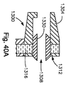
双方向縫合糸通し具10のブームアームハウジングは、図20A〜図20Dに説明したもの以外の構成を含むことができる。例えば、別の実施形態ではかつ図40A及び図40Bを参照すると、ブームアームハウジング内に往復要素を保持するために、エラストマー部材ではなくバネ荷重式横部材を利用することができる。図40Aに示すように、双方向縫合糸器具10は、本体1304、本体1304を通って延びるボア1308、及びロッキングインタフェース1312を有するブームアームハウジング1300を含むことができる。図40Aに示すように、ロッキングインタフェース1312は、ボア1320を有する横部材1316を含む。部材1316は、部材1316のボア1320がハウジング本体1304のボア1308と整列しないロック位置と部材1316のボア1320がハウジング本体1304のボア1308に整列する非ロック位置との間に部材1316を付勢することができるようにバネ荷重式である。図40Aに示すように、部材1316が非ロック位置にある時に、往復要素1330は、ブームアームハウジング1300に入ることができる。図40Bに示すように、部材1316がロック位置にある時に、部材1316の一部1338は、往復要素1330の背面側と係合し、それによってブームアームハウジング1300内に往復要素を保持する。作動機構は、ロック位置と非ロック位置の間で部材1316を選択的に付勢するのに使用することができる。   The boom arm housing of the bi-directional suture threader 10 can include configurations other than those described in FIGS. 20A-20D. For example, in another embodiment and referring to FIGS. 40A and 40B, a spring loaded cross member may be utilized rather than an elastomeric member to hold the reciprocating element within the boom arm housing. As shown in FIG. 40A, the bi-directional suture instrument 10 can include a boom arm housing 1300 having a body 1304, a bore 1308 extending through the body 1304, and a locking interface 1312. As shown in FIG. 40A, the locking interface 1312 includes a cross member 1316 having a bore 1320. Member 1316 biases member 1316 between a locked position where bore 1320 of member 1316 is not aligned with bore 1308 of housing body 1304 and an unlocked position where bore 1320 of member 1316 is aligned with bore 1308 of housing body 1304. It is spring loaded so that it can. As shown in FIG. 40A, the reciprocating element 1330 can enter the boom arm housing 1300 when the member 1316 is in the unlocked position. As shown in FIG. 40B, when member 1316 is in the locked position, a portion 1338 of member 1316 engages the back side of reciprocating element 1330, thereby retaining the reciprocating element within boom arm housing 1300. The actuation mechanism can be used to selectively bias member 1316 between a locked position and an unlocked position.

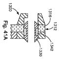
ロッキングインタフェース1312は、図40A及び図40Bに示すように、ブームアームハウジング1300の近位端の近くに、又は図41A及び図41Bに示すように、ブームアームハウジング1300のほぼ中心に位置することができる。ロッキングインタフェース1312が図41A及び図41Bに示すように中心の近くに位置する場合、往復要素1330は、ロッキングインタフェース1312が図41Bに示すようにロック位置にある時に、部材1316の部分1338によって係合されるように構成された凹部1342を含むことができる。   The locking interface 1312 may be located near the proximal end of the boom arm housing 1300, as shown in FIGS. 40A and 40B, or approximately in the center of the boom arm housing 1300, as shown in FIGS. 41A and 41B. it can. When the locking interface 1312 is located near the center as shown in FIGS. 41A and 41B, the reciprocating element 1330 is engaged by the portion 1338 of the member 1316 when the locking interface 1312 is in the locked position as shown in FIG. 41B. A recess 1342 configured to be included.

別の実施形態ではかつ図42A及び図42Bを参照すると、ブームアームハウジング内に往復要素を保持するために、エラストマー部材ではなく、内部ロープ機構を有する可撓性ポリマーチューブを利用することができる。図42Aに示すように、双方向縫合糸器具10は、本体1354、本体1354を通って延びるボア1358、及びロッキングインタフェース1362を有するブームアームハウジング1350を含むことができる。図42Aに示すように、ロッキングインタフェース1362は、内部ロープ機構1370を有する可撓性ポリマーチューブ1366を含む。可撓性ポリマーチューブは、ボア1358の内面に形成された内部溝又は凹部1374内に置かれている。往復要素1378が前進して凹部1374を過ぎた状態で、可撓性ポリマーチューブ1366は、図42Bに示すように、往復要素1378の近位端に対するバットレスをもたらすために内部ロープ1370を引くことによって収縮される。針は、次に、引っ込めることができ、往復要素1378は、ブームアームハウジング1350内に留まることになる。   In another embodiment and with reference to FIGS. 42A and 42B, a flexible polymer tube having an internal rope mechanism rather than an elastomeric member can be utilized to hold the reciprocating element within the boom arm housing. As shown in FIG. 42A, the bi-directional suture instrument 10 can include a boom arm housing 1350 having a body 1354, a bore 1358 extending through the body 1354, and a locking interface 1362. As shown in FIG. 42A, the locking interface 1362 includes a flexible polymer tube 1366 having an internal rope mechanism 1370. The flexible polymer tube is placed in an internal groove or recess 1374 formed in the inner surface of the bore 1358. With the reciprocating element 1378 advanced and past the recess 1374, the flexible polymer tube 1366 is pulled by pulling the inner rope 1370 to provide a buttress against the proximal end of the reciprocating element 1378, as shown in FIG. 42B. Shrinked. The needle can then be retracted and the reciprocating element 1378 will remain in the boom arm housing 1350.

ロッキングインタフェース1362は、図42A及び図42Bに示すように、ブームアームハウジング1350の近位端の近くに、又は図43A及び図43Bに示すように、ブームアームハウジング1350のほぼ中心に位置することができる。ロッキングインタフェース1362が図43A及び図43Bに示すように中心の近くに位置する場合、往復要素1378は、内部ロープ1370が収縮された時に、図43Bに示すように、可撓性ポリマーチューブ1366によって係合されるように構成された凹部1382を含むことができる。   The locking interface 1362 may be located near the proximal end of the boom arm housing 1350, as shown in FIGS. 42A and 42B, or approximately in the center of the boom arm housing 1350, as shown in FIGS. 43A and 43B. it can. When the locking interface 1362 is located near the center as shown in FIGS. 43A and 43B, the reciprocating element 1378 is engaged by a flexible polymer tube 1366 as shown in FIG. 43B when the inner rope 1370 is deflated. A recess 1382 configured to be mated can be included.

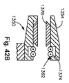
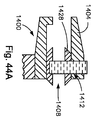
別の実施形態ではかつ図44A〜図44Dを参照すると、ブームアームハウジング内に往復要素を保持するために、エラストマー部材ではなく、c−クリップを利用することができる。図44Aに示すように、双方向縫合糸器具10は、本体1404を有するブームアームハウジング1400、本体1404を通って延びるボア1408、及びロッキングインタフェース1412を有するブームアームハウジング1400を含むことができる。図44C及び図44Dに示すように、ロッキングインタフェース1412は、遠位端の突起1420を有するc−クリップ1416を含む。図44Aに示すように、c−クリップ1416は、突起1420がボア1408内に延びるように、ハウジング本体1404内に形成された外部溝又は凹部1424内に置かれている。c−クリップ1416は、バネとして作用し、且つ、往復要素1428がc−クリップ1416を通ることを可能にするために、図44Aに示すように図44Cに示すように拡張する。往復要素1428が前進してc−クリップ1416を過ぎた状態で、c−クリップ1416は、収縮し、c−クリップ1416の端部上の突起1420は、図44Bに示すように、往復要素1428の近位端に対するバットレスとして作用する。針は、次に、引っ込めることができ、往復要素1428は、ブームアームハウジング1400内に留まることになる。   In another embodiment and with reference to FIGS. 44A-44D, c-clips can be utilized rather than elastomeric members to hold the reciprocating element within the boom arm housing. As shown in FIG. 44A, the bi-directional suture instrument 10 can include a boom arm housing 1400 having a body 1404, a bore 1408 extending through the body 1404, and a boom arm housing 1400 having a locking interface 1412. As shown in FIGS. 44C and 44D, the locking interface 1412 includes a c-clip 1416 having a distal end protrusion 1420. As shown in FIG. 44A, the c-clip 1416 is placed in an external groove or recess 1424 formed in the housing body 1404 such that the protrusion 1420 extends into the bore 1408. The c-clip 1416 acts as a spring and expands as shown in FIG. 44C as shown in FIG. 44A to allow the reciprocating element 1428 to pass through the c-clip 1416. With the reciprocating element 1428 advanced past the c-clip 1416, the c-clip 1416 contracts, and the protrusion 1420 on the end of the c-clip 1416 causes the reciprocating element 1428 to move as shown in FIG. 44B. Acts as a buttress against the proximal end. The needle can then be retracted and the reciprocating element 1428 will remain in the boom arm housing 1400.

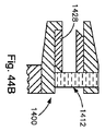
ロッキングインタフェース1412は、図44A及び図44Bに示すように、ブームアームハウジング1400の近位端の近くに、又は図45A及び図45Bに示すように、ブームアームハウジング1400のほぼ中心に位置することができる。ロッキングインタフェース1412が図45A及び図45Bに示すように中心の近くに位置する場合、往復要素1420は、図45Bに示すように、c−クリップ1416が収縮された時に、c−クリップ1416の突起1420によって係合されるように構成された凹部1432を含むことができる。   The locking interface 1412 may be located near the proximal end of the boom arm housing 1400, as shown in FIGS. 44A and 44B, or approximately in the center of the boom arm housing 1400, as shown in FIGS. 45A and 45B. it can. When the locking interface 1412 is located near the center as shown in FIGS. 45A and 45B, the reciprocating element 1420 can be configured so that the protrusion 1420 of the c-clip 1416 when the c-clip 1416 is contracted as shown in FIG. 45B. May include a recess 1432 configured to be engaged by.

別の実施形態ではかつ図46A及び図46Bを参照すると、ブームアームハウジングに往復要素を保持するために、エラストマー部材ではなく、板バネフィンガを利用することができる。図46Aに示すように、双方向縫合糸器具10は、本体1454、本体1454を通って延びるボア1458、及びロッキングインタフェース1462を有するブームアームハウジング1450を含むことができる。ロッキングインタフェース1462は、本体1454の前面壁1474から延びるアーム1470及びアーム1470から上へ延びる突起1478を有する板バネフィンガ1466である。フィンガ1466は、偏向可能であり、往復要素1486がボア1458内に前進すると、ボア1458の内面によって形成された凹部1482内に下方に付勢される。往復要素1486が前進して突起1478を過ぎた状態で、フィンガ1466は、上方に付勢され、突起1478は、図46Bに示すように、往復要素1486の近位端に対するバットレスとして作用する。針は、次に、引っ込めることができ、往復要素1486は、ブームアームハウジング1450内に留まることになる。   In another embodiment and with reference to FIGS. 46A and 46B, leaf spring fingers may be utilized rather than elastomeric members to hold the reciprocating element in the boom arm housing. As shown in FIG. 46A, the bi-directional suture instrument 10 can include a boom arm housing 1450 having a body 1454, a bore 1458 extending through the body 1454, and a locking interface 1462. The locking interface 1462 is a leaf spring finger 1466 having an arm 1470 extending from the front wall 1474 of the body 1454 and a protrusion 1478 extending upward from the arm 1470. Finger 1466 is deflectable and is biased downwardly into recess 1482 formed by the inner surface of bore 1458 as reciprocating element 1486 advances into bore 1458. With the reciprocating element 1486 advanced past the protrusion 1478, the finger 1466 is biased upward and the protrusion 1478 acts as a buttress against the proximal end of the reciprocating element 1486, as shown in FIG. 46B. The needle can then be retracted and the reciprocating element 1486 will remain in the boom arm housing 1450.

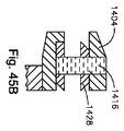
ロッキングインタフェース1462は、図46A及び図46Bに示すように、ブームアームハウジング1450の近位端の近くに、又は図47A及び図47Bに示すように、ブームアームハウジング1450のほぼ中心に位置することができる。ロッキングインタフェース1462が図47A及び図47Bに示すように中心の近くに位置する場合、往復要素1486は、図47Bに示すように、フィンガ1466が上方を付勢された時に、フィンガ1466の突起1478によって係合されるように構成された凹部1490を含むことができる。   The locking interface 1462 may be located near the proximal end of the boom arm housing 1450, as shown in FIGS. 46A and 46B, or approximately at the center of the boom arm housing 1450, as shown in FIGS. 47A and 47B. it can. When the locking interface 1462 is located near the center as shown in FIGS. 47A and 47B, the reciprocating element 1486 is moved by the protrusion 1478 of the finger 1466 when the finger 1466 is biased upward as shown in FIG. 47B. A recess 1490 configured to be engaged may be included.

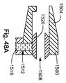
別の実施形態ではかつ図48A及び図48Bを参照すると、ブームアームハウジングに往復要素を保持するために、エラストマー部材ではなく、ワイヤバットレスを利用することができる。図48Aに示すように、双方向縫合糸器具10は、本体1504を有するブームアームハウジング1500、本体1504を通って延びるボア1508、及びロッキングインタフェース1512有するブームアームハウジング1500を含むことができる。ロッキングインタフェース1512は、往復要素1520の近位端に対するバットレスとして作用するようにボア1518からボア1508に手動で延長されるワイヤストップ1516である。往復要素1520が前進して突起1518を過ぎた状態で、ワイヤ1516は、往復要素1520より上方にワイヤ1516を前進させることによって展開され、従って、図48Bに示すように、往復要素1520の近位端に対するバットレスがもたらされる。針は、次に、引っ込めることができ、往復要素1520は、ブームアームハウジング1500内に留まることになる。   In another embodiment and with reference to FIGS. 48A and 48B, a wire buttress can be utilized rather than an elastomeric member to hold the reciprocating element in the boom arm housing. As shown in FIG. 48A, the bi-directional suture instrument 10 can include a boom arm housing 1500 having a body 1504, a bore 1508 extending through the body 1504, and a boom arm housing 1500 having a locking interface 1512. The locking interface 1512 is a wire stop 1516 that is manually extended from the bore 1518 to the bore 1508 to act as a buttress against the proximal end of the reciprocating element 1520. With the reciprocating element 1520 advanced past the protrusion 1518, the wire 1516 is deployed by advancing the wire 1516 above the reciprocating element 1520, and thus proximal to the reciprocating element 1520, as shown in FIG. 48B. A buttress against the edge is provided. The needle can then be retracted and the reciprocating element 1520 will remain in the boom arm housing 1500.

ロッキングインタフェース1512は、図48A及び図48Bに示すように、ブームアームハウジング1500の近位端の近くに、又は図49A及び図49Bに示すように、ブームアームハウジング1500のほぼ中心に位置することができる。ロッキングインタフェース1512が図49A及び図49Bに示すように中心の近くに位置する場合、往復要素1520は、図49Bに示すように、ワイヤ1516が延長された時に、ワイヤ1516によって係合されるように構成された凹部1524を含むことができる。ワイヤ1516は、円筒形、正方形などを含むあらゆる形状とすることができる。   The locking interface 1512 may be located near the proximal end of the boom arm housing 1500, as shown in FIGS. 48A and 48B, or approximately in the center of the boom arm housing 1500, as shown in FIGS. 49A and 49B. it can. If the locking interface 1512 is located near the center as shown in FIGS. 49A and 49B, the reciprocating element 1520 will be engaged by the wire 1516 when the wire 1516 is extended, as shown in FIG. 49B. A configured recess 1524 can be included. The wire 1516 can be any shape including cylindrical, square, and the like.

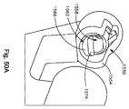
別の実施形態ではかつ図50A及び図50Bを参照すると、ブームアームハウジングに往復要素を保持するために、エラストマー部材ではなく、バネ荷重式ゲートを利用することができる。図50Aに示すように、双方向縫合糸器具10は、本体1554、本体1554を通って延びるボア1558、及びロッキングインタフェース1562を有するブームアームハウジング1550を含むことができる。ロッキングインタフェース1562は、バネ1570により上方を付勢されるゲート1566を含む。図示のように、ゲート1566は、上端の傾斜面1574を含み、且つ、上方を付勢された時にボア1558内に部分的に延びる。ゲート1566は、往復要素の近位端に対するバットレスとして作用する。作動において、針又は往復要素は、ゲート1566の傾斜面1574に接触し、それによって下方に付勢される。ゲートが下に付勢されると、往復要素は、ボア1558内に入ることができ、完全に入った状態で、ゲート1566は、バネ1570により上方を付勢することができ、それによってブームアームハウジング1550に往復要素を取外し可能に連結する。針は、次に、引っ込めることができ、一方、往復要素は、ブームアームハウジング1550内に留まることになる。   In another embodiment and with reference to FIGS. 50A and 50B, a spring loaded gate may be utilized rather than an elastomeric member to hold the reciprocating element in the boom arm housing. As shown in FIG. 50A, the bi-directional suture instrument 10 can include a boom arm housing 1550 having a body 1554, a bore 1558 that extends through the body 1554, and a locking interface 1562. The locking interface 1562 includes a gate 1566 that is biased upward by a spring 1570. As shown, the gate 1566 includes an upper sloped surface 1574 and extends partially into the bore 1558 when biased upward. Gate 1566 acts as a buttress for the proximal end of the reciprocating element. In operation, the needle or reciprocating element contacts the inclined surface 1574 of the gate 1566 and is thereby biased downward. When the gate is biased down, the reciprocating element can enter the bore 1558 and, once fully inserted, the gate 1566 can be biased upward by a spring 1570, thereby causing the boom arm to move. A reciprocating element is removably coupled to the housing 1550. The needle can then be retracted, while the reciprocating element will remain within the boom arm housing 1550.

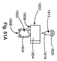
別の実施形態ではかつ図51A〜図51Eを参照すると、針に往復要素を取外し可能に連結してブームアームハウジングに往復要素を取外し可能に連結するために、一連の溝及びトラップを利用することができる。図示のように、双方向縫合糸器具10は、針1612によって係合されるボア1608を形成する本体1604を有するチューブ状の往復要素1600を含むことができる。針1612は、本体1616から上方へ延びる複数の外部リブ1620のような係合特徴部と、リブ1620の近くの本体1616内に形成された複数の三角形のトラップ1624とを有する本体1616を含む。トラップ1624は、往復要素1600が本体1616上に置かれることに可能にするためにリブ1620からある一定の距離だけ離間している。往復要素1600の本体1604は、針1612の各リブ1620に整列するように構成された軸線方向スロット1628を含む。複数のリブ1632は、本体1604の外面から延び、且つ、スロット1628に整列する。往復要素1600は、往復要素本体1604の近位端及び遠位端上に形成された三角形のトラップ1640も含む。往復要素1600の遠位端上のトラップ1640は、針1612のリブ1620からオフセットしており、且つ、往復要素1600が針1612に連結されることが望ましい時にリブの近位先端を受け入れかつ捕捉するように付勢される。針1612及び連結された往復要素1600は、次に、ブームアームハウジングまで前進することができる。   In another embodiment and with reference to FIGS. 51A-51E, utilizing a series of grooves and traps to removably connect the reciprocating element to the needle and removably connect to the boom arm housing. Can do. As shown, the bi-directional suture instrument 10 can include a tubular reciprocating element 1600 having a body 1604 that forms a bore 1608 engaged by a needle 1612. Needle 1612 includes a body 1616 having engagement features such as a plurality of external ribs 1620 extending upwardly from body 1616 and a plurality of triangular traps 1624 formed in body 1616 proximate to ribs 1620. Trap 1624 is spaced a distance from rib 1620 to allow reciprocating element 1600 to be placed on body 1616. The body 1604 of the reciprocating element 1600 includes an axial slot 1628 configured to align with each rib 1620 of the needle 1612. A plurality of ribs 1632 extend from the outer surface of the body 1604 and align with the slots 1628. The reciprocating element 1600 also includes a triangular trap 1640 formed on the proximal and distal ends of the reciprocating element body 1604. Trap 1640 on the distal end of reciprocating element 1600 is offset from rib 1620 of needle 1612 and receives and captures the proximal tip of the rib when it is desired that reciprocating element 1600 be coupled to needle 1612. Energized as follows. Needle 1612 and the associated reciprocating element 1600 can then be advanced to the boom arm housing.

ブームアームハウジング1650は、ボア1658を形成する本体1654を含む。ボア1658は、往復要素1604の外部リブ1632に整列するように構成された軸線方向スロットを形成する。ハウジング1650のボア1658内には、往復要素1600の遠位先端及び針1612の遠位先端と相互作用するように構成されたバネのような反力要素がある。反力要素は、針1612の外部リブ1620と相互作用するように構成された一連の軸線方向スロット及び三角形のトラップ、及び往復要素1604の遠位端と相互作用するように構成された好ましくは平坦な表面を含む。更に、ブームアームハウジング1650は、往復要素1604の近位端上で三角形のトラップと相互作用するように構成されたボア1658内に軸線方向スロットの遠位側に位置する一連の三角形のトラップを含む。   Boom arm housing 1650 includes a body 1654 that forms a bore 1658. The bore 1658 forms an axial slot configured to align with the outer rib 1632 of the reciprocating element 1604. Within the bore 1658 of the housing 1650 is a spring-like reaction element configured to interact with the distal tip of the reciprocating element 1600 and the distal tip of the needle 1612. The reaction force element is preferably a flat, configured to interact with a series of axial slots and triangular traps configured to interact with the outer ribs 1620 of the needle 1612 and the distal end of the reciprocating element 1604. Surface. In addition, the boom arm housing 1650 includes a series of triangular traps located distal to the axial slot in a bore 1658 configured to interact with the triangular traps on the proximal end of the reciprocating element 1604. .

作動において、往復要素1604は、往復要素1604の外部リブ1632をハウジング1650の軸線方向スロットに整列させることにより、ブームアームハウジング1650のボア1658に入る。針1612が更に前進すると、針1612の外部リブ1620は、反力要素内の軸線方向スロットと整列し、針1612は、前進して反力要素を通ることができる。同時に、往復要素1604は、前進してブームのハウジング1650内の軸線方向スロットを過ぎた状態で、反力要素の平坦な表面に遭遇し、平坦な表面は、ブームの先端の近位端に向けて往復要素1604を押し、往復要素1604の近位端上の三角形のトラップ1640がブームのハウジング1650内の軸線方向スロットの遠位端上の三角形のトラップと相互作用してそれによって捕捉されると、往復要素1604が回転する。往復要素1604のこの回転により、往復要素1604内の軸線方向スロット1628が、反力要素の軸線方向スロット及び針1612の外部リブ1620に整列すると、針1612を自由にブームアームハウジング1650から引っ込め、且つ、本体によって実施される保護鞘に引っ込めることができ、往復要素1604が、遠位側ブームのハウジング1650に取外し可能に連結されたままになり、従って、往復要素1604及び接続した縫合糸ストランドが、欠損部の近くの組織の下側上に維持される。   In operation, the reciprocating element 1604 enters the bore 1658 of the boom arm housing 1650 by aligning the outer rib 1632 of the reciprocating element 1604 with the axial slot of the housing 1650. As the needle 1612 is further advanced, the external ribs 1620 of the needle 1612 are aligned with the axial slots in the reaction force element, and the needle 1612 can be advanced and pass through the reaction force element. At the same time, the reciprocating element 1604 encounters the flat surface of the reaction element with advancement past the axial slot in the boom housing 1650, the flat surface facing the proximal end of the boom tip. When pushing the reciprocating element 1604, the triangular trap 1640 on the proximal end of the reciprocating element 1604 interacts with and is captured by the triangular trap on the distal end of the axial slot in the boom housing 1650. The reciprocating element 1604 rotates. This rotation of the reciprocating element 1604 causes the needle 1612 to retract freely from the boom arm housing 1650 when the axial slot 1628 in the reciprocating element 1604 is aligned with the axial slot of the reaction force element and the outer rib 1620 of the needle 1612, and The reciprocating element 1604 remains removably coupled to the distal boom housing 1650 so that the reciprocating element 1604 and the connected suture strand can be Maintained on the underside of the tissue near the defect.

ブームアームは、次に、操作され、例えば、針1612が安全に保護された状態で、例えば、欠損部の反対の下側の欠損部の近くの組織の下面上の別の区域まで回転され、最適に移動した状態で、針1612は、サムリングを使用してサムリングロック及びサムリングロックキャップを非ロック位置に維持し、ハンドル14に対して再び遠位側に平行移動され、従って、針1612は、強制的に上側から欠損部の近くの第2の部位の組織の下側まで通り、針1612の遠位端は、往復要素1604と再係合する。針1612の外部リブ1620は、遠位側移動で往復要素1604の内部上の軸線方向スロット1628内で平行移動する。針1612が更に前進すると、針1612の遠位端の近位側の三角形のトラップ1624は、往復要素1604の近位端上の三角形のトラップ1640に接触して往復要素1604と係合し、往復要素1604を回転させる。この回転する位置で、針1612の外部リブ1620は、往復要素1604の内部上の軸線方向スロット1628とはもはや整列せず、その代わりに往復要素1604の遠位端上の三角形のトラップ1640に整列し、往復要素1604を針1612により再捕捉することができ、従って、往復要素1604は、針1612が引っ込むと針1612と連結する。   The boom arm is then manipulated, for example, rotated to another area on the lower surface of the tissue, for example, near the lower defect opposite the defect, with the needle 1612 securely protected, With optimal movement, the needle 1612 uses the thumb ring to maintain the thumb ring lock and thumb ring lock cap in the unlocked position, and is translated again distally relative to the handle 14, thus the needle 1612. Is forced from the upper side to the lower side of the tissue at the second site near the defect and the distal end of the needle 1612 re-engages with the reciprocating element 1604. The outer rib 1620 of the needle 1612 translates in an axial slot 1628 on the interior of the reciprocating element 1604 with distal movement. As the needle 1612 is further advanced, the triangular trap 1624 proximal to the distal end of the needle 1612 contacts the triangular trap 1640 on the proximal end of the reciprocating element 1604 and engages the reciprocating element 1604 to reciprocate. The element 1604 is rotated. In this rotated position, the outer rib 1620 of the needle 1612 is no longer aligned with the axial slot 1628 on the interior of the reciprocating element 1604, but instead is aligned with the triangular trap 1640 on the distal end of the reciprocating element 1604. The reciprocating element 1604 can then be recaptured by the needle 1612 so that the reciprocating element 1604 is coupled to the needle 1612 when the needle 1612 is retracted.

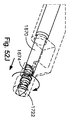
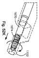
別の実施形態ではかつ図52A〜図52Lを参照すると、針に往復要素を取外し可能に連結してブームアームハウジングに往復要素を取外し可能に連結するために、ネジ付き係合特徴部及びネジ付きロッキングインタフェースを利用することができる。図52A及び図52Bに示すように、双方向縫合糸器具10は、カニューレ針1670及び針1670に選択的に連結される双端往復要素1674を含むことができる。針1670は、本体1678を通って延びるボア又はチャンネル1682を有する本体1678を含む。ボア1682の遠位端は、雌ネジ1686のような係合特徴部を含む。往復要素1674は、針1670の遠位端に取外し可能に連結される。   In another embodiment and with reference to FIGS. 52A-52L, a threaded engagement feature and threaded for removably coupling a reciprocating element to a needle and removably coupling a reciprocating element to a boom arm housing. A locking interface can be used. As shown in FIGS. 52A and 52B, the bi-directional suture instrument 10 can include a cannula needle 1670 and a dual end reciprocating element 1647 that is selectively coupled to the needle 1670. Needle 1670 includes a body 1678 having a bore or channel 1682 extending through body 1678. The distal end of the bore 1682 includes an engagement feature such as an internal thread 1686. The reciprocating element 1674 is removably coupled to the distal end of the needle 1670.

往復要素1674は、往復要素1674に縫合糸を締結する半径方向溝1694と、本体1690から後方に延びる第1のヘッド1698と、本体1690から前方に延びる第2のヘッド1702とを形成する本体1690を含む。第1のヘッド1698は、針1670の雌ネジ1686と係合するように構成された雄ネジ1706のような係合特徴部を含む。第2のヘッド1702は、雄ネジ1710及び雄ネジ1710の前方の針先端1714のようなロッキング機構を含む。雄ネジ1706及び雄ネジ1710は、反対のネジ山を有する。例えば、雄ネジ1706は、左ネジであり、雄ネジ1710は、右ネジであり、これは、針1670が往復要素1674から分離することを可能にすることになる。雌ネジ及び雄ネジは、異なるピッチを有することができる。   The reciprocating element 1694 includes a body 1690 that forms a radial groove 1694 that fastens a suture to the reciprocating element 1694, a first head 1698 that extends rearward from the body 1690, and a second head 1702 that extends forward from the body 1690. including. The first head 1698 includes an engagement feature, such as an external thread 1706, configured to engage an internal thread 1686 of the needle 1670. The second head 1702 includes a locking mechanism such as a male screw 1710 and a needle tip 1714 in front of the male screw 1710. Male thread 1706 and male thread 1710 have opposite threads. For example, male thread 1706 is a left-hand thread and male thread 1710 is a right-hand thread, which will allow needle 1670 to separate from reciprocating element 1674. The female screw and the male screw can have different pitches.

往復要素1674は、先端アクチュエータの作動を通じて、ブームアームハウジング1718のようなブームアームハウジング内で針1670から取外し可能であることが好ましい。ブームアームハウジング1718は、貫通して延びるボア1726を有する本体1722を含む。ボア1726の遠位端は、往復要素1674の雄ネジ1710と係合するように構成された雌ネジ1730のようなロッキングインタフェースを含む。往復要素1674の近位端は、往復要素1674に取り付けられている縫合糸のためのクリアランスを作成するために間隙1740を含む。   Reciprocating element 1674 is preferably removable from needle 1670 within a boom arm housing, such as boom arm housing 1718, through actuation of a tip actuator. Boom arm housing 1718 includes a body 1722 having a bore 1726 extending therethrough. The distal end of the bore 1726 includes a locking interface such as an internal thread 1730 configured to engage the external thread 1710 of the reciprocating element 1673. The proximal end of the reciprocating element 1684 includes a gap 1740 to create a clearance for the suture attached to the reciprocating element 1647.

作動において、オペレータは、取り付けられた縫合糸を有する往復要素1674を針1670上に係合させ、任意的に、縫合糸緊張具に縫合糸を通す。オペレータは、人指し指及び中指でハンドルを把持し、アクチュエータがハンドルから近位側に引っ込められた位置にある状態で、サムリング30に親指を通す。ブームアームの遠位部分は、組織の上側から組織の下側まで椎間板の環線維症による亀裂のような組織欠損部に通され、且つ、欠損部に接近するために組織欠損部の近くに縫合糸を通す最適構成で回転されるか、又はそうでなければ欠損部の近くに位置決めされる。サムリングは、ハンドルに対して遠位側に平行移動され、従って、アクチュエータ及び針1670がハンドルに対して遠位側に前進し、且つ、針1670の遠位端及びそれに取り付けられた往復要素1674、並びに往復要素40に取り付けられた縫合糸が欠損部の近くの組織を通過すると、往復要素1674とブームアームハウジング1718が強制的に接触される。往復要素1674の遠位先端がブームアームハウジング1718の雌ネジ1674の近位端に接触した時に、先端アクチュエータが作動され(すなわち、右回転)、針1670及び往復要素1674が回転し、従って、往復要素1674の雄ネジ1710が、ブームアームハウジング1718の雌ネジ1674と係合する。針1670の更に別の回転により、針1670からのネジ付き往復要素1674の分離が発生し、往復要素1674は、ブームアームハウジング1718に連結されたままになる。換言すれば、何らかの時点で針1670が回転すると、往復要素1674は、ブームアームハウジング1718内の回転を止め、針1670は、引き続き回転して、針1670は、往復要素1674から離脱する。この離脱は、往復要素1674の雄ネジ1706及び雄ネジ1710の反対のネジ切りのために可能にされる。   In operation, the operator engages reciprocating element 1647 with attached suture on needle 1670 and optionally passes the suture through a suture tensioner. The operator holds the handle with the index and middle fingers, and passes the thumb through the thumb ring 30 with the actuator in a position retracted proximally from the handle. The distal portion of the boom arm is threaded through the tissue defect, such as a fissure due to annulus fibrosis, from the upper side of the tissue to the lower side of the tissue, and sutured near the tissue defect to gain access to the defect It is rotated in an optimal configuration for threading or otherwise positioned near the defect. The thumb ring is translated distally with respect to the handle, so that the actuator and needle 1670 are advanced distally with respect to the handle, and the distal end of the needle 1670 and the reciprocating element 1673 attached thereto, As the suture attached to the reciprocating element 40 passes through tissue near the defect, the reciprocating element 1674 and the boom arm housing 1718 are forcibly contacted. When the distal tip of the reciprocating element 1674 contacts the proximal end of the internal thread 1684 of the boom arm housing 1718, the tip actuator is actuated (ie, rotated clockwise), causing the needle 1670 and the reciprocating element 1647 to rotate, and thus reciprocating. A male thread 1710 of element 1674 engages a female thread 1673 of boom arm housing 1718. Yet another rotation of the needle 1670 causes separation of the threaded reciprocating element 1674 from the needle 1670, which remains connected to the boom arm housing 1718. In other words, if the needle 1670 rotates at some point, the reciprocating element 1684 stops rotating in the boom arm housing 1718, the needle 1670 continues to rotate, and the needle 1670 is disengaged from the reciprocating element 1684. This disengagement is made possible due to the opposite threading of the male thread 1706 and male thread 1710 of the reciprocating element 1674.

針1674は、次に、本体によって具現化された保護鞘内に引っ込められる。ブームアームは、次に、操作され、例えば、針1670が安全に保護された状態で、例えば、欠損部の反対の下側上の欠損部の近くの組織の下面上の別の区域まで回転され、最適に移動した状態で、針1670は、サムリングを使用してハンドルに対して再び遠位側に平行移動され、従って、針1670は、強制的に上側から欠損部の近くの第2の部位の組織の下側まで通り、針1670の遠位端が、往復要素1674の雄ネジ1706の近位縁部に接触する。次に、先端アクチュエータは、再作動され(すなわち、左回転)、針1670が反対方向に回転し、従って、針1670の雌ネジ1686が、往復要素1674の近位端上の雄ネジ1706と係合し、従って、往復要素1674は、針1670に連結される。針1670の更に別の回転により、往復要素1674は、ブームアームハウジング1718から分離する。サムリングは、次に、ハンドルに対して近位側に引っ込められ、アクチュエータ及び針1670の対応する引っ込みが発生し、従って、針1670の遠位端及び縫合糸を有する往復要素1674が、欠損部の近くの組織の下側から外へ欠損部の近くの組織の上部を通る。これらの段階は、欠損部のサイズ及び組織の特性に基づいて、必要に応じて1回又はそれよりも多くの回数だけ繰り返すことができる。   Needle 1674 is then retracted into a protective sheath embodied by the body. The boom arm is then manipulated and rotated, for example, to another area on the lower surface of the tissue near the defect on the lower side opposite the defect, for example, with the needle 1670 securely protected. With optimal movement, the needle 1670 is translated distally again with respect to the handle using the thumb ring, so that the needle 1670 is forced from the upper side to the second site near the defect. The distal end of the needle 1670 contacts the proximal edge of the external thread 1706 of the reciprocating element 1684. The tip actuator is then re-actuated (ie, rotated counterclockwise) and the needle 1670 rotates in the opposite direction, so that the internal thread 1686 of the needle 1670 engages with the external thread 1706 on the proximal end of the reciprocating element 1674. Thus, the reciprocating element 1674 is coupled to the needle 1670. Further rotation of the needle 1670 separates the reciprocating element 1674 from the boom arm housing 1718. The thumb ring is then retracted proximally with respect to the handle, and a corresponding retraction of the actuator and needle 1670 occurs, so that the reciprocating element 1674 with the distal end of the needle 1670 and the suture is removed from the defect. Passes from the underside of the nearby tissue to the top of the tissue near the defect. These steps can be repeated one or more times as needed based on the size of the defect and the tissue characteristics.

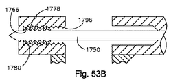
別の実施形態ではかつ図53A〜図53Cを参照すると、針は、雌ネジではなく雄ネジを含む。図53Aに示すように、双方向縫合糸器具10は、針1750及び針1750の外面に選択的に連結された往復要素1754を含むことができる。針1750は、遠位端に近接する雄ネジ1766のような係合特徴部を有する本体1758を含む。往復要素1754は、針1750の遠位端に取外し可能に連結される。   In another embodiment and with reference to FIGS. 53A-53C, the needle includes a male thread rather than a female thread. As shown in FIG. 53A, the bi-directional suture instrument 10 can include a needle 1750 and a reciprocating element 1754 that is selectively coupled to the outer surface of the needle 1750. Needle 1750 includes a body 1758 having an engagement feature, such as male thread 1766 proximate the distal end. Reciprocating element 1754 is removably coupled to the distal end of needle 1750.

往復要素1754は、貫通して延びる軸線方向ボア1774を有する本体1770を含む。図示のように、ボア1774は、針1750の雄ネジ1766と係合するように構成された雌ネジ1778のような係合特徴部を含む。往復要素本体1754は、雄ネジ1780のようなロッキング機構も含む。雌ネジ1778及び雄ネジ1780は、反対のネジ山を有する。例えば、雌ネジ1778は、左ネジであり、雄ネジ1780は、右ネジであり、これは、針1670が往復要素1674から分離することを可能にすることになる。   The reciprocating element 1754 includes a body 1770 having an axial bore 1774 extending therethrough. As shown, the bore 1774 includes an engagement feature such as an internal thread 1778 that is configured to engage an external thread 1766 of the needle 1750. The reciprocating element body 1754 also includes a locking mechanism such as an external thread 1780. Female thread 1778 and male thread 1780 have opposite threads. For example, the female thread 1778 is a left-hand thread and the male thread 1780 is a right-hand thread, which will allow the needle 1670 to separate from the reciprocating element 1684.

往復要素1754は、先端アクチュエータの作動を通じて、ブームアームハウジング1784のようなブームアームハウジング内で針1750から取外し可能であることが好ましい。ブームアームハウジング1784は、貫通して延びるボア1792を有する本体1788を含む。ボア1792は、往復要素1754の雄ネジ1780と係合するように構成された雌ネジ1796のようなロッキングインタフェースを含む。往復要素1754は、図52A〜図52Lを参照して説明した実施形態と同様に、図53B及び図53Cに示すようにブームアームハウジング1784に連結することができる。往復要素1754は、説明した構成に限定されず、且つ、図52A〜図52Lで上述したように双端とすることができ、第1のヘッドは、針1750の雄ネジ1766と係合するように構成された雌ネジを形成するボアを有することを理解すべきである。   Reciprocating element 1754 is preferably removable from needle 1750 within a boom arm housing, such as boom arm housing 1784, through actuation of a tip actuator. Boom arm housing 1784 includes a body 1788 having a bore 1792 extending therethrough. Bore 1792 includes a locking interface such as a female thread 1796 configured to engage male thread 1780 of reciprocating element 1754. The reciprocating element 1754 can be coupled to the boom arm housing 1784 as shown in FIGS. 53B and 53C, similar to the embodiment described with reference to FIGS. 52A-52L. The reciprocating element 1754 is not limited to the configuration described, and can be double-ended as described above in FIGS. 52A-52L so that the first head engages the male thread 1766 of the needle 1750. It should be understood that it has a bore configured to form a female thread.

別の実施形態ではかつ図54A〜図54Nを参照すると、往復要素に針をかつブームアームハウジングに往復要素を取外し可能に連結するために、ネジではなく、ウイングを利用することができる。図示のように、双方向縫合糸器具10は、ウイング付き往復要素1804に取外し可能に連結されたウイング付き針1800を含むことができる。図示のように、針1800は、針1800の遠位上部の近くの本体1808の外面から半径方向に外方に延びるウイング1812のような係合特徴部を有する本体1808を含む。各ウイング1812は、傾斜前面1816を含む。図示のように、ウイング1812は、針本体1808の両側に延び、且つ、往復要素1804と係合するように構成される。   
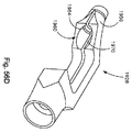
In another embodiment and with reference to FIGS. 54A-54N, wings rather than screws can be utilized to removably couple the needle to the reciprocating element and the reciprocating element to the boom arm housing. As shown, the bi-directional suture instrument 10 can include a winged needle 1800 removably coupled to a winged reciprocating element 1804. As shown, the needle 1800 includes a body 1808 having engagement features such as wings 1812 that extend radially outward from the outer surface of the body 1808 near the distal upper portion of the needle 1800. Each wing 1812 includes an inclined front surface 1816. As shown, wings 1812 extend to opposite sides of needle body 1808 and are configured to engage reciprocating element 1804.

往復要素1804は、遠位端1828のような針の近くの本体1820の外面から半径方向に外方に延びるウイング1824のようなロッキング機構と、本体1820の近位端から本体1820に延びるボア1832とを有する本体1820を含む。各ウイング1824は、往復要素1804を簡単に通ることを可能にする傾斜前面1830を含む。往復要素1804は、半径方向スロット1840のような係合特徴部内に至る1対の軸線方向スロット1836を有するボア1832を含み、軸線方向スロットは、針1800に往復要素1804を取外し可能に連結するために針1800のウイング1812によって係合されるように構成される。   The reciprocating element 1804 includes a locking mechanism such as a wing 1824 that extends radially outward from the outer surface of the body 1820 near the needle, such as the distal end 1828, and a bore 1832 that extends from the proximal end of the body 1820 to the body 1820. A body 1820 having Each wing 1824 includes an angled front surface 1830 that allows easy passage through the reciprocating element 1804. The reciprocating element 1804 includes a bore 1832 having a pair of axial slots 1836 that extend into engagement features, such as radial slots 1840, for releasably connecting the reciprocating element 1804 to the needle 1800. And is configured to be engaged by a wing 1812 of the needle 1800.

往復要素1804及び針1800は、ブームアームハウジング1850のようなブームアームハウジング内に前進させることができる。図示のように、ブームアームハウジング1850は、往復要素1804の近位端と類似のものである。換言すれば、ブームアームハウジング1850は、半径方向スロット1862のようなロッキングインタフェース内に至る軸線方向スロット1858を形成するボア1854を含み、軸線方向スロットは、往復要素1804のウイング1824によって係合されるように構成される。   The reciprocating element 1804 and the needle 1800 can be advanced into a boom arm housing, such as the boom arm housing 1850. As shown, the boom arm housing 1850 is similar to the proximal end of the reciprocating element 1804. In other words, boom arm housing 1850 includes a bore 1854 that forms an axial slot 1858 that extends into a locking interface, such as radial slot 1862, which is engaged by wing 1824 of reciprocating element 1804. Configured as follows.

作動において、針1800は、ウイング1812を往復要素1804の軸線方向スロット1836に整列させることにより、往復要素1804に連結される。針1800は、次に、前進してスロット1836を通り、半径方向スロット1840に入る。針は、次に、180°回転し(右回転)、ウイング1812と半径方向スロット1840の間のインタフェースが、針1800に往復要素1804を連結する。往復要素1804及び針1800は、次に、ブームアームハウジング1850に向けて平行移動される。往復要素1804は、往復要素1804のウイング1824をブームアームハウジング1850の軸線方向スロット1858に整列させることにより、ブームアームハウジング1850と係合する。往復要素1804は、ウイング1824がブームアームハウジング1850の半径方向スロット1862と係合するまで更に前進する。往復要素1804を有する針1800は、次に、回転し、それによってブームアームハウジング1850に往復要素を選択的に連結する。針1800は、次に、引っ込めることができ、それによって往復要素1804は、ブームアームハウジング1850内に残る。これらの段階は、欠損部のサイズ及び組織の特性に基づいて、必要に応じて1回又はそれよりも多くの回数だけ繰り返すことができる。   In operation, the needle 1800 is coupled to the reciprocating element 1804 by aligning the wing 1812 with the axial slot 1836 of the reciprocating element 1804. Needle 1800 is then advanced through slot 1836 and into radial slot 1840. The needle then rotates 180 ° (right rotation) and the interface between the wing 1812 and the radial slot 1840 couples the reciprocating element 1804 to the needle 1800. The reciprocating element 1804 and the needle 1800 are then translated toward the boom arm housing 1850. The reciprocating element 1804 engages the boom arm housing 1850 by aligning the wing 1824 of the reciprocating element 1804 with the axial slot 1858 of the boom arm housing 1850. The reciprocating element 1804 is further advanced until the wing 1824 engages the radial slot 1862 of the boom arm housing 1850. Needle 1800 with reciprocating element 1804 then rotates, thereby selectively coupling the reciprocating element to boom arm housing 1850. Needle 1800 can then be retracted, thereby leaving reciprocating element 1804 in boom arm housing 1850. These steps can be repeated one or more times as needed based on the size of the defect and the tissue characteristics.

代替的に、図54A〜図54Nに示す実施形態の係合特徴部を逆にすることができる。例えば、図55に示すように、双方向縫合糸通し器具10は、往復要素1874に取外し可能に連結された針1870を含むことができる。図示のように、針1870は、本体1878の外面から半径方向に内方に延びる凹部1882のような係合特徴部を有する本体1878を含む。凹部1882は、後壁1890を形成する半径方向スロット1886に対して近位側に延びる。図示のように、凹部1882は、往復要素1874と係合するように構成される。   Alternatively, the engagement features of the embodiment shown in FIGS. 54A-54N can be reversed. For example, as shown in FIG. 55, the bi-directional suture threading device 10 can include a needle 1870 that is removably coupled to a reciprocating element 1874. As shown, the needle 1870 includes a body 1878 having an engagement feature such as a recess 1882 that extends radially inwardly from the outer surface of the body 1878. The recess 1882 extends proximally relative to the radial slot 1886 that forms the rear wall 1890. As shown, recess 1882 is configured to engage reciprocating element 1874.

往復要素1874は、ボア1898と針1870の係合特徴部にほぼ同一であるロッキング機構とを有する本体1894を含む。ボア1898は、針1870の凹部及び後壁により係合し、それによって針1870に往復要素1874を取外し可能に連結するように構成された半径方向スロットのような係合特徴部を形成する軸線方向の突起を含む。   The reciprocating element 1874 includes a body 1894 having a bore 1898 and a locking mechanism that is substantially identical to the engagement feature of the needle 1870. Bore 1898 is engaged axially by the recess and rear wall of needle 1870, thereby forming an axial feature such as a radial slot configured to removably couple reciprocating element 1874 to needle 1870. Including protrusions.

往復要素1874及び針1870は、ブームアームハウジング1906のようなブームアームハウジング内に前進させることができる。図示のように、ブームアームハウジング1906は、往復要素1874の近位端と類似のものである。換言すれば、ブームアームハウジング1906は、ブームアームハウジング1906に往復要素1874を取外し可能に連結するために往復要素1874の凹部及び後壁によって係合されるように構成された半径方向スロットのような係合特徴部を形成する軸線方向突起1912を形成するボア1910を含む。   Reciprocating element 1874 and needle 1870 can be advanced into a boom arm housing, such as boom arm housing 1906. As shown, the boom arm housing 1906 is similar to the proximal end of the reciprocating element 1874. In other words, the boom arm housing 1906 may be a radial slot configured to be engaged by the recess and rear wall of the reciprocating element 1874 to removably connect the reciprocating element 1874 to the boom arm housing 1906. It includes a bore 1910 that forms an axial protrusion 1912 that forms an engagement feature.

図56A〜図56Dに示すように、双方向縫合糸通し具10は、他の特徴及び設計を含むことができる。例えば、図56Aに示すように、双方向縫合糸通し具10は、ハンドル1920、ハンドル1920を通って延びる部材1924、及び部材1924の端部から延びるブームアーム1928を含むことができる。双方向縫合糸通し具10は、部材1924のボア内で平行移動可能なドライバ1932を含むことができる。図56Bに示すように、ドライバ1932は、ノブ1936、ノブ1936から延びるシャフト1940、及びシャフト1940の遠位端から延びる針1944を含む。針1944は、図53A〜図53Cを参照して説明した針と類似のものであり、かつ図53Cに示す往復要素1950のような往復要素に針1944を連結するために外に延びるネジ山1948を含む係合特徴部を含む。針1944及び往復要素1944のネジ山は、ラチェット型接続又は回転型接続で互いと係合することができる。   As shown in FIGS. 56A-56D, the bi-directional suture threader 10 can include other features and designs. For example, as shown in FIG. 56A, the bi-directional suture threader 10 can include a handle 1920, a member 1924 extending through the handle 1920, and a boom arm 1928 extending from the end of the member 1924. Bidirectional suture threader 10 may include a driver 1932 that is translatable within the bore of member 1924. As shown in FIG. 56B, the driver 1932 includes a knob 1936, a shaft 1940 extending from the knob 1936, and a needle 1944 extending from the distal end of the shaft 1940. Needle 1944 is similar to the needle described with reference to FIGS. 53A-53C and extends outwardly to connect needle 1944 to a reciprocating element such as reciprocating element 1950 shown in FIG. 53C. Including an engagement feature. The threads of the needle 1944 and the reciprocating element 1944 can engage each other in a ratchet type connection or a rotary type connection.

図56Cに示すように、往復要素は、針係合部分1952及び組織係合部分1953を有する本体1951を含む。図示のように、針係合部分1953は、ネジ山のような係合特徴部を形成する内面を有するボア1954を含む。針係合部分1953のネジ山は、往復要素1950に針1944を取外し可能に連結するために針1944のネジ山1948と係合するように構成される。図示のように、組織係合部分1953は、遠位側に延び、且つ、雄ネジ1955のようなロッキング機構を含む。ネジ山1955は、ブームアーム1928のブームアームハウジング1956(図56Dに図示)によって形成されたロッキング特徴部と係合するように構成される。   As shown in FIG. 56C, the reciprocating element includes a body 1951 having a needle engaging portion 1952 and a tissue engaging portion 1953. As shown, needle engagement portion 1953 includes a bore 1954 having an inner surface that forms an engagement feature such as a thread. The thread of the needle engaging portion 1953 is configured to engage the thread 1948 of the needle 1944 to removably couple the needle 1944 to the reciprocating element 1950. As shown, the tissue engaging portion 1953 extends distally and includes a locking mechanism such as an external thread 1955. Thread 1955 is configured to engage a locking feature formed by boom arm housing 1956 (shown in FIG. 56D) of boom arm 1928.

図56Dに示すように、ブームアームハウジング1956は、貫通して延びるボア1960を有する。ボア1960は、雌ネジ1964を形成する内面を有する。ブームアームは、ブームアーム1928の本体を通って延びるスロット1970も含む。スロット1970により、ブームアームハウジング1956は、往復要素1950がボア1960内に配置された時に僅かに分離することができる。従って、ネジ山を利用する実施形態に対しては、往復要素をラチェット式に入れることができるので回転量を低減することができる。往復要素をブームアームハウジング1956から取り外すために、往復要素は、ブームアームハウジング1956から往復要素を抜くために回す又は回転させることができる。   
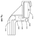
As shown in FIG. 56D, the boom arm housing 1956 has a bore 1960 that extends therethrough. The bore 1960 has an inner surface that forms an internal thread 1964. The boom arm also includes a slot 1970 that extends through the body of the boom arm 1928. The slot 1970 allows the boom arm housing 1956 to be slightly separated when the reciprocating element 1950 is disposed within the bore 1960. Therefore, for the embodiment using the screw thread, the reciprocating element can be put in a ratchet type, so that the amount of rotation can be reduced. To remove the reciprocating element from the boom arm housing 1956, the reciprocating element can be turned or rotated to remove the reciprocating element from the boom arm housing 1956.

図57A〜図57Eを参照すると、双方向縫合糸通し器具10は、縫合糸を通すことができる通路を骨構造体内に作成するように構成することができる。図示のように、双方向縫合糸器具10は、ブームアーム2000が縫合糸を通すことができる通路を骨構造体内に作成することを可能にするように構成された千枚通し先端2004を有するブームアーム2000を含むことができる。代替的に、双方向縫合糸器具10は、針2008の先端が縫合糸を通すことができる通路を骨構造体内に作成することを可能にするように構成された千枚通し先端2012を有する針2008を含むことができる。ブームアーム及び針の両方が千枚通し先端を含むことができることを理解すべきである。   Referring to FIGS. 57A-57E, the bi-directional suture threading device 10 can be configured to create a passage in the bone structure through which suture can be passed. As shown, the bi-directional suture instrument 10 has a boom arm 2000 having a staggered tip 2004 configured to allow the boom arm 2000 to create a passage in the bone structure through which the suture can pass. Can be included. Alternatively, the bi-directional suture instrument 10 includes a needle 2008 having a staggered tip 2012 configured to allow the tip of the needle 2008 to create a passage in the bone structure through which the suture can pass. Can be included. It should be understood that both the boom arm and the needle can include a staggered tip.

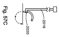
図57Bに示すように、嵌め込みロッド2016は、器具10に取り付けることができ、且つ、ブームアーム2000上に形成された嵌め込み壁に接触するように構成することができる。代替的に、図57C〜図57Eに示すように、嵌め込みロッド2016は、針2008が嵌め込まれる時に針2008を把持及び保持するように構成されたグリップ2020を含むことができる。このような特徴を有する双方向縫合糸通し器具10を使用して輪状周縁断裂を治療することができる。   As shown in FIG. 57B, the fitting rod 2016 can be attached to the instrument 10 and can be configured to contact a fitting wall formed on the boom arm 2000. Alternatively, as shown in FIGS. 57C-57E, the fitting rod 2016 can include a grip 2020 configured to grip and hold the needle 2008 when the needle 2008 is fitted. A ring-shaped peripheral tear can be treated using the bi-directional suture threading device 10 having such characteristics.

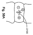
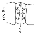
双方向縫合糸器具10は、図58A〜図58Fに示すような様々な異なる縫合糸通し構成を使用して軟部組織欠損部を治療するのに使用することができる。例えば、図58Aに示すような単一の縫い目2100、図58Bに示すようなボックスマットレス縫い目2104、図58Cに示すようなマットレス縫い目2108、図58Dに示すような逆マットレス縫い目2112、図58Eに示すような垂直マットレス縫い目2116、及び図58Fに示すような逆垂直マットレス縫い目2120がある。欠損部を取り囲む縫合糸の最終構成は、単一の直線ループ、マットレス縫い目、又はマットレス縫い目の組合せとすることができ、又は関節鏡視下手術、腹腔鏡手術、整形外科手術、心臓血チューブ外科、又は一般的な外科手術の当業技術で公知の軟部組織治療のいくつかの縫合パターンのいずれかを含むループを含むことができる。   The bi-directional suture instrument 10 can be used to treat soft tissue defects using a variety of different suture threading configurations as shown in FIGS. 58A-58F. For example, a single seam 2100 as shown in FIG. 58A, a box mattress seam 2104 as shown in FIG. 58B, a mattress seam 2108 as shown in FIG. 58C, a reverse mattress seam 2112 as shown in FIG. 58D, and FIG. 58E. There is a vertical mattress seam 2116 such as this, and an inverted vertical mattress seam 2120 as shown in FIG. 58F. The final configuration of the suture surrounding the defect can be a single linear loop, mattress seam, or a combination of mattress seams, or arthroscopic surgery, laparoscopic surgery, orthopedic surgery, cardiovascular tube surgery Or a loop that includes any of several suture patterns of soft tissue treatment known in the art of general surgery.

図58Aに示すように、単一の縫い目2100は、欠損部の片側の組織の全厚に縫合糸を通すことによって形成され、且つ、欠損部の反対側の組織の全厚に通して取り出される。縫合糸は、最初に内側から外側に(すなわち、組織の第1の側から第2の側に)通し、次に、組織の外側から内側に(すなわち、第2の側から第1の側に)取り出すことができ、又は最初に組織の外側から内側に、次に、内側から外側に通すことができる。外側から内側への通し及び内側から外側への通しのいずれかの組合せを用いることができる。   As shown in FIG. 58A, a single seam 2100 is formed by passing the suture through the entire thickness of the tissue on one side of the defect and removed through the entire thickness of the tissue opposite the defect. . The suture is first threaded from the inside to the outside (ie, from the first side of the tissue to the second side) and then from the outside of the tissue to the inside (ie, from the second side to the first side). ) Or can be passed first from outside to inside of the tissue and then from inside to outside. Any combination of outer to inner threading and inner to outer threading can be used.

図58Bに示すように、ボックス縫い目2104は、欠損部にわたって及び次に椎間板の近位側から椎間板の遠位側に水平に縫合糸を通すことによって形成される。縫合糸は、次に、再び欠損部にわたって通され、縫合糸の自由端は、次に、縫合を完了するために結ばれて結び目になる。結び目は、環欠損部の外側上に着座する。   As shown in FIG. 58B, the box seam 2104 is formed by passing the suture horizontally across the defect and then from the proximal side of the disc to the distal side of the disc. The suture is then passed again over the defect and the free ends of the suture are then tied and knotted to complete the suture. The knot sits on the outside of the ring defect.

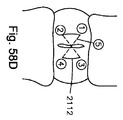
図58C示すように、ボックス縫い目2108は、椎間板の近位側から椎間板の遠位側に、且つ、次に椎間板の近位側に向って斜めに欠損部にわたって縫合糸を通すことによって形成される。これらの段階が繰り返され、縫合糸の自由端は、次に、縫合を完了するために結ばれて結び目になる。結び目は、環欠損部の外側上に着座する。図58Dに示すように、結び目は、逆マットレス縫い目2112のためのゼロプロフィール閉鎖に向けて欠損部より下方の環壁の内側上に着座する。   As shown in FIG. 58C, the box seam 2108 is formed by passing the suture over the defect diagonally from the proximal side of the disc to the distal side of the disc and then toward the proximal side of the disc. . These steps are repeated, and the free end of the suture is then tied into a knot to complete the suture. The knot sits on the outside of the ring defect. As shown in FIG. 58D, the knot sits on the inside of the annular wall below the defect towards the zero profile closure for the reverse mattress seam 2112.

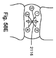
図58E及び図58Fに示すように、垂直マットレス縫い目及び逆垂直マットレス縫い目は、椎間板の近位側の欠損部にわたって、且つ、次に椎間板の近位側に向って斜めに欠損部にわたって縫合糸を通すことによって形成することができる。これらの段階が繰り返されて縫合が完了される。図示のように、結び目は、図58E示すように環状欠損部の外側、又は図58Fに示すように欠損部の内側とすることができる。   As shown in FIGS. 58E and 58F, the vertical mattress seam and the reverse vertical mattress seam thread the suture over the defect on the proximal side of the intervertebral disc and then diagonally toward the proximal side of the intervertebral disc. It can be formed by passing. These steps are repeated to complete the suturing. As shown, the knot can be outside the annular defect as shown in FIG. 58E or inside the defect as shown in FIG. 58F.

双方向縫合糸器具10は、図58G〜図58Iに示すように、椎体のような骨要素の近くの軟部組織修復に向けて縫合糸を通すように構成することができる。図示のように、縫合糸の自由端2200は、欠損部に最も近い椎体から離れて最も遠い欠損部の側の環壁の全厚に通され、且つ、次に欠損部の隣にtransosseus手法を通じて椎体を通って形成された穴に通される。穴は、図57A〜図57Dを参照して上述したように千枚通し先端又は千枚通しの先端を有する針を使用して作成することができ、又は予め穿孔することができる。縫合糸は、最初に椎体に、次に環の全厚に通すことができる。このような方法はまた、上腕骨のより少ない結節への断裂回旋腱板腱の再取り付けのような骨要素の近くの他の軟部組織に対して構成することができる。   The bi-directional suture instrument 10 can be configured to pass sutures for soft tissue repair near bone elements such as vertebral bodies, as shown in FIGS. 58G-58I. As shown, the free end 2200 of the suture is threaded through the full thickness of the annulus on the side of the defect farthest away from the vertebral body closest to the defect, and then the transosseus technique next to the defect Through and through a hole formed through the vertebral body. The holes can be created using a needle having a staggered tip or a staggered tip as described above with reference to FIGS. 57A-57D, or can be pre-drilled. The suture can be passed through the vertebral body first and then through the full thickness of the annulus. Such a method can also be configured for other soft tissues near the bone element, such as reattachment of a torn rotator cuff tendon to a lesser humerus nodule.

広範囲にわたる発明の概念から逸脱することなく、上述の実施形態に変更を行うことができることは当業者によって認められるであろう。従って、本発明は、開示した特定の実施形態に限定されず、修正を本発明の説明によって定める本発明の精神及び範囲内に含めるように意図していることが理解される。例えば、往復要素に針を取外し可能に接続するのに、他の係合特徴部を利用することができ、Morseテーパ連結、磁気式保持、圧入連結、及び当業技術で公知の様々な他の機械式接続のような他の機構をブームアームハウジングに往復要素を取外し可能に接続するのに利用することができる。更に、上述の1つの実施形態のいずれの特徴も、本明細書に説明する他の実施形態に適用可能とすることができる。例えば、上述の各往復要素は、チューブ状であり、且つ、針の上に装着することができ、又は各々は、近位端が針に連結されるように構成された針のような先端を含むことができる。   It will be appreciated by those skilled in the art that modifications can be made to the above-described embodiments without departing from the broad inventive concept. Accordingly, it is to be understood that the invention is not limited to the specific embodiments disclosed, but that modifications are intended to be included within the spirit and scope of the invention as defined by the description of the invention. For example, other engagement features can be utilized to removably connect the needle to the reciprocating element, such as the Morse taper connection, magnetic retention, press-fit connection, and various other known in the art. Other mechanisms, such as a mechanical connection, can be utilized to removably connect the reciprocating element to the boom arm housing. Further, any feature of one embodiment described above may be applicable to other embodiments described herein. For example, each of the reciprocating elements described above is tubular and can be mounted on a needle, or each has a needle-like tip configured such that the proximal end is coupled to the needle. Can be included.

10 双方向縫合糸通し器具
14 ハンドル
26 アクチュエータ要素
50 本体
54 グリップ
10 Bidirectional suture threading device 14 Handle 26 Actuator element 50 Body 54 Grip

Claims (73)

軟部組織欠損部に接近するように構成された双方向縫合糸通し器具であって、前記縫合糸通し器具は、
針受け取りチャンネルを形成する本体部材と、
前記本体部材から延びるブームアームであって、前記ブームアームが、前記本体部材から離間したブームアームハウジングを有し、組織受け取り間隙が、前記ブームアームハウジングと前記本体部材の間に配置された前記ブームアームと、
針の遠位端が前記ブームアームハウジング内に延びる前進位置と針の前記遠位端が前記ブームアームハウジングから引っ込められた後退位置との間で前記本体部材の前記チャンネル内で往復平行移動可能な前記針と、
前記針にかつ前記ブームアームハウジングに取外し可能に連結するように構成された往復要素と、を有し、
(i)前記往復要素が前記針に取外し可能に連結されたときに、前記ブームアームハウジングに対する前記針の回転が、前記往復要素を前記ブームアームハウジングに取外し可能に連結させ、且つ、(ii)前記往復要素が前記ブームアームハウジングに取外し可能に連結されたときに、前記往復要素に対する前記針の回転が、前記針を前記往復要素に取外し可能に連結させる、ことを特徴とする双方向縫合糸通し器具。
A bi-directional suture threading device configured to approach a soft tissue defect, wherein the suture threading device includes:
A body member forming a needle receiving channel;
A boom arm extending from the main body member, wherein the boom arm has a boom arm housing spaced from the main body member, and the tissue receiving gap is disposed between the boom arm housing and the main body member. Arm,
Reciprocally translatable within the channel of the body member between an advanced position in which the distal end of the needle extends into the boom arm housing and a retracted position in which the distal end of the needle is retracted from the boom arm housing The needle;
A reciprocating element configured to be removably coupled to the needle and to the boom arm housing;
(I) when the reciprocating element is removably coupled to the needle, rotation of the needle relative to the boom arm housing causes the reciprocating element to be removably coupled to the boom arm housing; and (ii) Bidirectional suture wherein rotation of the needle relative to the reciprocating element removably couples the needle to the reciprocating element when the reciprocating element is removably coupled to the boom arm housing. Threading instrument.
(i)前記針は、係合特徴部を有し、(ii)前記往復要素も、係合特徴部を有し、且つ、(iii)前記往復要素が、前記ブームアームハウジングに取外し可能に連結された時に、前記往復要素に対する前記針の回転が、前記針の前記係合特徴部を前記往復要素の前記係合特徴部と係合させて前記針を前記往復要素に取外し可能に連結することを特徴とする請求項1に記載の双方向縫合糸通し器具。   (I) the needle has an engagement feature; (ii) the reciprocating element also has an engagement feature; and (iii) the reciprocating element is removably coupled to the boom arm housing. When rotated, rotation of the needle relative to the reciprocating element causes the engagement feature of the needle to engage the engagement feature of the reciprocating element to detachably connect the needle to the reciprocating element. The bi-directional suture threading device according to claim 1. (i)前記往復要素は、ロッキング機構を有し、(ii)前記ブームアームハウジングは、ロッキングインタフェースを有し、且つ、(iii)前記往復要素が前記針に取外し可能に連結された時に、前記ブームアームハウジングに対する前記針の回転が、前記往復要素の前記ロッキング機構を前記ブームアームハウジングの前記ロッキングインタフェースと係合させて前記往復要素を前記ブームアームハウジングに取外し可能に連結することを特徴とする請求項2に記載の双方向縫合糸通し器具。   (I) the reciprocating element has a locking mechanism; (ii) the boom arm housing has a locking interface; and (iii) when the reciprocating element is removably coupled to the needle, Rotating the needle with respect to the boom arm housing engages the locking mechanism of the reciprocating element with the locking interface of the boom arm housing to removably connect the reciprocating element to the boom arm housing. The bidirectional suture threading device according to claim 2. 前記往復要素の係合特徴部及び前記往復要素の前記ロッキング機構は、反対の向きのネジ山であることを特徴とする請求項3に記載の双方向縫合糸通し器具。   The bi-directional suture threading device of claim 3, wherein the engagement feature of the reciprocating element and the locking mechanism of the reciprocating element are oppositely oriented threads. 前記針及び前記往復要素の前記係合特徴部は、ネジ山であり、前記針の前記ネジ山は、前記往復要素の前記ネジ山と係合するように構成されることを特徴とする請求項2に記載の双方向縫合糸通し器具。   The engagement feature of the needle and the reciprocating element is a thread, and the thread of the needle is configured to engage the thread of the reciprocating element. 2. A bidirectional suture threading device according to 2. 前記針の前記ネジ山は、前記針の外面から延びることを特徴とする請求項5に記載の双方向縫合糸通し器具。   The bi-directional suture threading device of claim 5, wherein the thread of the needle extends from an outer surface of the needle. (i)前記往復要素は、ボアを形成し、(ii)前記往復要素の前記ネジ山は、前記ボアの内面から延び、且つ、(iii)前記ボアは、前記針を受け取るように構成されることを特徴とする請求項6に記載の双方向縫合糸通し器具。   (I) the reciprocating element forms a bore; (ii) the thread of the reciprocating element extends from an inner surface of the bore; and (iii) the bore is configured to receive the needle. The bi-directional suture threading device according to claim 6. 前記ボアは、前記往復要素を貫通して延び、前記針は、前記往復要素の前記ボアを通って延びるように構成されることを特徴とする請求項7に記載の双方向縫合糸通し器具。   The bi-directional suture passer of claim 7, wherein the bore extends through the reciprocating element and the needle is configured to extend through the bore of the reciprocating element. 前記針は、ボアを有し、前記針の前記ネジ山は、前記ボアの内面から延びることを特徴とする請求項5に記載の双方向縫合糸通し器具。   6. The bi-directional suture threading device of claim 5, wherein the needle has a bore, and the thread of the needle extends from an inner surface of the bore. (i)前記往復要素の前記ネジ山は、前記往復要素の外面から延び、且つ、(ii)前記針の前記ボアは、前記往復要素を受け取るように構成されることを特徴とする請求項9に記載の双方向縫合糸通し器具。   10. The thread of the reciprocating element extends from an outer surface of the reciprocating element, and (ii) the bore of the needle is configured to receive the reciprocating element. A bi-directional suture threading device according to claim 1. (i)前記往復要素の前記ロッキング機構及び前記ブームアームハウジングの前記ロッキングインタフェースは、ネジ山であり、(ii)前記往復要素の前記ネジ山は、前記往復要素の外面から延び、(iii)前記ブームアームハウジングの前記ネジ山は、前記ブームアームハウジングによって形成されたボアの内面から延び、且つ、(iv)前記往復要素の前記ネジ山は、前記ブームアームハウジングの前記ネジ山と係合するように構成されることを特徴とする請求項3に記載の双方向縫合糸通し器具。   (I) the locking mechanism of the reciprocating element and the locking interface of the boom arm housing are threads; (ii) the thread of the reciprocating element extends from an outer surface of the reciprocating element; The thread of the boom arm housing extends from the inner surface of the bore formed by the boom arm housing, and (iv) the thread of the reciprocating element engages the thread of the boom arm housing. The bidirectional suture threading device according to claim 3, wherein the bidirectional suture threading device is configured as described above. (i)前記針の前記係合特徴部は、前記針の本体から外へ延びるウイングを有し、(ii)前記往復要素は、前記針の前記ウイングを受け取るように構成された軸線方向スロットを形成するボアを有し、(iii)前記軸線方向スロットは、前記往復要素の前記係合特徴部の中に延び、(iv)前記往復要素の前記係合特徴部は、半径方向スロットを有し、且つ、(v)前記針の回転が、前記針の前記ウイングを前記往復要素の前記半径方向スロットと係合させ、それによって前記往復要素を前記針に取外し可能に連結することを特徴とする請求項3に記載の双方向縫合糸通し器具。   (I) the engagement feature of the needle has a wing extending outward from the body of the needle, and (ii) the reciprocating element has an axial slot configured to receive the wing of the needle. And (iii) the axial slot extends into the engagement feature of the reciprocating element, and (iv) the engagement feature of the reciprocating element has a radial slot. And (v) rotation of the needle engages the wing of the needle with the radial slot of the reciprocating element, thereby removably connecting the reciprocating element to the needle. The bidirectional suture threading device according to claim 3. (i)前記往復要素の前記ロッキング機構は、前記往復要素の本体から外へ延びるウイングを有し、(ii)前記ブームアームハウジングは、前記往復要素の前記ウイングを受け取るように構成された軸線方向スロットを形成するボアを有し、(iii)前記軸線方向スロットは、前記ブームアームハウジングの前記ロッキングインタフェースの中に延び、(iv)前記ブームアームハウジングの前記ロッキングインタフェースは、半径方向スロットを有し、且つ、(v)前記往復要素の回転が、前記往復要素の前記ウイングを前記ブームアームハウジングの前記半径方向スロットと係合させ、それによって前記往復要素を前記ブームアームハウジングに取外し可能に連結することを特徴とする請求項12に記載の双方向縫合糸通し器具。   (I) the locking mechanism of the reciprocating element has a wing extending outward from a body of the reciprocating element; and (ii) the boom arm housing is axially configured to receive the wing of the reciprocating element A bore forming a slot; (iii) the axial slot extends into the locking interface of the boom arm housing; and (iv) the locking interface of the boom arm housing has a radial slot. And (v) rotation of the reciprocating element engages the wing of the reciprocating element with the radial slot of the boom arm housing, thereby removably connecting the reciprocating element to the boom arm housing. The bidirectional suture threading device according to claim 12, wherein the bidirectional suture threading device is provided. 前記針に連結された先端アクチュエータを更に有し、前記先端アクチュエータの回転が、前記針を回転させることを特徴とする請求項1に記載の双方向縫合糸通し器具。   The bi-directional suture threading device according to claim 1, further comprising a tip actuator coupled to the needle, wherein rotation of the tip actuator rotates the needle. 前記針の近位端に連結された作動部材を更に有し、前記作動部材の平行移動が、前記針を平行移動させることを特徴とする請求項1に記載の双方向縫合糸通し器具。   The bi-directional suture threading device of claim 1, further comprising an actuating member coupled to the proximal end of the needle, wherein translation of the actuating member translates the needle. 前記ブームアームハウジング又は前記針のいずれかは、千枚通し先端を有することを特徴とする請求項1に記載の双方向縫合糸通し器具。   2. The bidirectional suture threading device according to claim 1, wherein either the boom arm housing or the needle has a threading tip. 軟部組織欠損部に縫合糸を通す方法であって、本方法は、
針の係合特徴部が往復要素の係合特徴部と係合し、それによって前記往復要素を針に取外し可能に連結させるように針を回転させる段階と、
前記針及び前記往復要素をブームアームハウジング内に前進させる段階と、
前記往復要素のロッキング機構が、前記ブームアームハウジングのロッキングインタフェースと係合し、それによって前記往復要素を前記ブームアームハウジングに取外し可能に連結させるように前記往復要素を回転させる段階と、を有することを特徴とする方法。
A method of passing a suture through a soft tissue defect,
Rotating the needle so that the engagement feature of the needle engages the engagement feature of the reciprocating element, thereby removably connecting the reciprocating element to the needle;
Advancing the needle and the reciprocating element into a boom arm housing;
Rotating the reciprocating element such that the reciprocating element locking mechanism engages a locking interface of the boom arm housing, thereby removably connecting the reciprocating element to the boom arm housing. A method characterized by.
前記針を回転させて前記往復要素から前記針を離脱させる段階と、
前記往復要素を前記ブームアームハウジングに連結されたままに残しながら前記ブームアームハウジングから前記針を引っ込める段階と、
を更に有することを特徴とする請求項17に記載の方法。
Rotating the needle to disengage the needle from the reciprocating element;
Retracting the needle from the boom arm housing while leaving the reciprocating element connected to the boom arm housing;
18. The method of claim 17, further comprising:
前記針を前記ブームアームハウジング内に前進させる段階と、
前記針の係合特徴部が、前記往復要素の前記係合特徴部と再係合し、それによって前記往復要素を前記針に再連結させるように前記針を回転させる段階と、
前記往復要素の前記ロッキング機構が、前記ブームアームハウジングの前記ロッキングインタフェースを離脱し、それによって前記往復要素を前記ブームアームハウジングから分離するように前記往復要素を回転させる段階と、
前記針及び前記往復要素を前記ブームアームハウジングから前記軟部組織欠損部を通して引っ込める段階と、
を更に有することを特徴とする請求項18に記載の方法。
Advancing the needle into the boom arm housing;
Rotating the needle to reengage the engagement feature of the needle with the engagement feature of the reciprocating element, thereby reconnecting the reciprocating element to the needle;
The locking mechanism of the reciprocating element disengages the locking interface of the boom arm housing, thereby rotating the reciprocating element to separate the reciprocating element from the boom arm housing;
Retracting the needle and the reciprocating element from the boom arm housing through the soft tissue defect;
The method of claim 18 further comprising:
前記針及び前記往復要素の前記係合特徴部は、ネジ山であることを特徴とする請求項17に記載の方法。   The method of claim 17, wherein the engagement feature of the needle and the reciprocating element is a thread. 前記針の前記ネジ山は、前記針の外面から延びることを特徴とする請求項20に記載の方法。   21. The method of claim 20, wherein the thread of the needle extends from an outer surface of the needle. (i)前記往復要素は、ボアを形成し、(ii)前記往復要素の前記ネジ山は、前記ボアの内面から延び、且つ、(iii)前記ボアは、前記針を受け取るように構成されることを特徴とする請求項21に記載の方法。   (I) the reciprocating element forms a bore; (ii) the thread of the reciprocating element extends from an inner surface of the bore; and (iii) the bore is configured to receive the needle. The method according to claim 21, wherein: 前記ボアは、前記往復要素を貫通して延び、前記針は、前記往復要素の前記ボアを通って延びるように構成されることを特徴とする請求項22に記載の方法。   23. The method of claim 22, wherein the bore extends through the reciprocating element and the needle is configured to extend through the bore of the reciprocating element. (i)前記往復要素は、前記往復要素が前記ブームアームハウジングに連結された時に回転するのを止め、且つ、(ii)前記針の回転の継続が、前記針を前記往復要素から離脱させることを特徴とする請求項17に記載の方法。   (I) the reciprocating element stops rotating when the reciprocating element is coupled to the boom arm housing, and (ii) continued rotation of the needle causes the needle to disengage from the reciprocating element. The method of claim 17, wherein: (i)前記往復要素は、前記往復要素を前記ブームアームハウジングに連結するために第1の方向に回転され、且つ、(ii)前記往復要素は、前記往復要素を前記ブームアームハウジングから分離するために前記第1の方向と反対の第2の方向に回転されることを特徴とする請求項17に記載の方法。   (I) the reciprocating element is rotated in a first direction to couple the reciprocating element to the boom arm housing, and (ii) the reciprocating element separates the reciprocating element from the boom arm housing. 18. The method of claim 17, wherein the method is rotated in a second direction opposite to the first direction. 軟部組織欠損部に接近するように構成された双方向縫合糸通し器具であって、前記縫合糸通し器具は、
針受け取りチャンネルを形成する本体部材と、
前記本体部材から延びるブームアームであって、前記ブームアームが、前記本体部材から離間したブームアームハウジングを有し、そのために組織受け取り間隙が、前記ブームアームハウジングと前記本体部材の間に配置される前記ブームアームと、
前記針の遠位端が前記ブームアームハウジング内に延びる前進位置と、前記針の前記遠位端が前記ブームアームハウジングから引っ込められる後退位置との間で前記本体部材の前記チャンネル内で往復平行移動可能な針であって、前記針が、チャンネルと、延長位置と後退位置の間で前記チャンネル内に少なくとも部分的に配置された係合特徴部とを有する前記針と、
ネジ山を担持するように構成された往復要素と、を有し、
(i)前記係合特徴部は、前記延長位置において前記往復要素を前記針に取外し可能に連結し、且つ、前記係合特徴部は、前記引っ込められた位置において前記往復要素を前記針から分離する、ことを特徴とする双方向縫合糸通し器具。
A bi-directional suture threading device configured to approach a soft tissue defect, wherein the suture threading device includes:
A body member forming a needle receiving channel;
A boom arm extending from the body member, the boom arm having a boom arm housing spaced from the body member, whereby a tissue receiving gap is disposed between the boom arm housing and the body member. The boom arm;
Reciprocal translation in the channel of the body member between an advanced position in which the distal end of the needle extends into the boom arm housing and a retracted position in which the distal end of the needle is retracted from the boom arm housing A possible needle, the needle having a channel and an engagement feature disposed at least partially within the channel between an extended position and a retracted position;
A reciprocating element configured to carry a thread,
(I) the engagement feature removably couples the reciprocating element to the needle in the extended position, and the engagement feature separates the reciprocating element from the needle in the retracted position. A bi-directional suture threading device.
(i)前記往復要素は、前記針を受け取るように構成されたボアを有することを特徴とする請求項26に記載の双方向縫合糸通し器具。   27. The bi-directional suture threading device of claim 26, wherein (i) the reciprocating element has a bore configured to receive the needle. 前記係合特徴部は、ワイヤストップの遠位部分が、ワイヤストップが延長位置にある時に前記往復要素と係合するような前記針チャンネル内で平行移動可能なワイヤストップであることを特徴とする請求項26に記載の双方向縫合糸通し器具。   The engagement feature is characterized in that the distal portion of the wire stop is a wire stop that is translatable within the needle channel such that the wire stop engages the reciprocating element when the wire stop is in the extended position. 27. A bi-directional suture threading device according to claim 26. 前記針の前記チャンネル内で平行移動可能な楔を更に有し、前記楔は、前記係合特徴部と係合するように構成されることを特徴とする請求項26に記載の双方向縫合糸通し器具。   27. The bi-directional suture of claim 26, further comprising a wedge that is translatable within the channel of the needle, the wedge configured to engage the engagement feature. Threading instrument. (i)前記係合特徴部は、前記往復要素によって形成された軸線方向フィンガであり、前記軸線方向フィンガは、前記フィンガが延長位置にある時に前記針の前記チャンネルと係合する突起を有し、且つ、(ii)前記楔の遠位の平行移動が、前記軸線方向フィンガを前記針の前記チャンネルから離脱させることを特徴とする請求項29に記載の双方向縫合糸通し器具。   (I) the engagement feature is an axial finger formed by the reciprocating element, the axial finger having a protrusion that engages the channel of the needle when the finger is in an extended position; 30. The bi-directional suture passer of claim 29, wherein (ii) distal translation of the wedge disengages the axial finger from the channel of the needle. 前記針の周りに配置されたスリーブを更に有し、前記スリーブは、前記軸線方向フィンガが前記針の前記チャンネルから離脱した時に前記針から前記往復要素を押し離すように構成されることを特徴とする請求項30に記載の双方向縫合糸通し器具。   Further comprising a sleeve disposed around the needle, the sleeve configured to push the reciprocating element away from the needle when the axial finger is disengaged from the channel of the needle. The bidirectional suture threading device according to claim 30. (i)前記係合特徴部は、ボールストップであり、且つ、(ii)前記楔の遠位の平行移動が、前記ボールストップを前記チャンネルから延ばして前記往復要素と係合させることを特徴とする請求項29に記載の双方向縫合糸通し器具。   (I) the engagement feature is a ball stop, and (ii) a distal translation of the wedge extends the ball stop from the channel to engage the reciprocating element. 30. A bidirectional suture threading device according to claim 29. 前記ボールストップは、半球状の上部及び三角形の底部を有することを特徴とする請求項32に記載の双方向縫合糸通し器具。   33. The bi-directional suture threading device of claim 32, wherein the ball stop has a hemispherical top and a triangular bottom. (i)前記係合特徴部は、前記チャンネルの遠位壁から延びるフィンガストップであり、且つ、(ii)前記楔の遠位の平行移動が、前記フィンガストップを前記チャンネルから延ばして前記往復要素と係合させ、それによって前記往復要素を前記針に取外し可能に連結することを特徴とする請求項29に記載の双方向縫合糸通し器具。   (I) the engagement feature is a fin gas top extending from a distal wall of the channel; and (ii) a distal translation of the wedge extends the fin gas top from the channel and the reciprocating element. 30. The bi-directional suture threading device of claim 29, wherein the bi-directional suture threading device is releasably engaged thereby removably connecting the reciprocating element to the needle. 前記フィンガストップは、前記楔によって係合される傾斜面を有することを特徴とする請求項34に記載の双方向縫合糸通し器具。   35. A bi-directional suture threading device according to claim 34, wherein the fin gas top has an inclined surface engaged by the wedge. (i)前記係合特徴部は、単一のピボット点で取り付けられた2つのフィンガを有する鋏ストップであり、且つ、(ii)前記楔の遠位の平行移動が、前記フィンガの各々を前記ピボット点に関して回転させ、それによって各フィンガのヘッドが前記チャンネルから延びて前記往復要素と係合することを可能にすることを特徴とする請求項29に記載の双方向縫合糸通し器具。   (I) the engagement feature is a heel stop having two fingers attached at a single pivot point, and (ii) a distal translation of the wedge causes each of the fingers to 30. The bi-directional suture threading device of claim 29, wherein the bi-directional suture threading device is rotated about a pivot point, thereby allowing the head of each finger to extend from the channel and engage the reciprocating element. (i)前記係合特徴部は、単一のピボット点に関して回転可能なブーツストップであり、且つ、(ii)前記楔の遠位の平行移動が、前記ブーツストップを前記ピボット点に関して回転させ、それによって前記ブーツストップの一部分が前記チャンネルから延びて前記往復要素と係合することを可能にすることを特徴とする請求項29に記載の双方向縫合糸通し器具。   (I) the engagement feature is a boot stop rotatable with respect to a single pivot point, and (ii) a distal translation of the wedge causes the boot stop to rotate with respect to the pivot point; 30. The bi-directional suture threading device of claim 29, thereby allowing a portion of the boot stop to extend from the channel and engage the reciprocating element. 前記係合特徴部は、前記係合特徴部が延長位置にある時に前記往復要素の遠位端と係合することを特徴とする請求項27に記載の双方向縫合糸通し器具。   28. The bi-directional suture threading device of claim 27, wherein the engagement feature engages a distal end of the reciprocating element when the engagement feature is in an extended position. 前記往復要素の前記ボアは、凹部を形成し、前記係合特徴部は、前記係合特徴部が作動された時に前記凹部の中に延びることを特徴とする請求項27に記載の双方向縫合糸通し器具。   28. The bi-directional suture of claim 27, wherein the bore of the reciprocating element forms a recess, and the engagement feature extends into the recess when the engagement feature is actuated. Threading instrument. 前記ブームアームハウジングは、前記往復要素を前記ブームアームハウジング内に保持するように構成されたロッキングインタフェースを有することを特徴とする請求項27に記載の双方向縫合糸通し器具。   28. The bi-directional suture threading device of claim 27, wherein the boom arm housing has a locking interface configured to retain the reciprocating element within the boom arm housing. 前記ロッキングインタフェースは、前記往復要素が前記ブームアームハウジング内に配置された時に前記往復要素と係合するように構成されたエラストマーを有することを特徴とする請求項40に記載の双方向縫合糸通し器具。   41. The bi-directional suture threader of claim 40, wherein the locking interface comprises an elastomer configured to engage the reciprocating element when the reciprocating element is disposed within the boom arm housing. Instruments. (i)前記ブームアームハウジングは、ボアを形成し、(ii)前記ロッキングインタフェースは、ボアを有する横部材を有し、且つ、(iii)前記横部材は、前記横部材の前記ボアが前記ブームアームハウジングの前記ボアと整列しないロック位置と、前記部材の前記ボアが前記ブームアームハウジングの前記ボアと整列する非ロック位置との間で付勢されるように構成されることを特徴とする請求項40に記載の双方向縫合糸通し器具。   (I) the boom arm housing forms a bore; (ii) the locking interface includes a transverse member having a bore; and (iii) the transverse member is configured such that the bore of the transverse member is the boom. The arm housing is configured to be biased between a locked position that is not aligned with the bore of the arm housing and an unlocked position in which the bore of the member is aligned with the bore of the boom arm housing. Item 42. The bidirectional suture threading device according to Item 40. (i)前記ロッキングインタフェースは、内部ロープ機構を有する可撓性ポリマーチューブを有し、且つ、(ii)前記ロープ機構は、収縮し、それによって前記ポリマーチューブを収縮させて前記往復要素と係合するように構成されることを特徴とする請求項40に記載の双方向縫合糸通し器具。   (I) the locking interface has a flexible polymer tube with an internal rope mechanism, and (ii) the rope mechanism contracts, thereby contracting the polymer tube to engage the reciprocating element 41. The bi-directional suture threading device of claim 40, configured to: (i)前記ロッキングインタフェースは、C−クリップの内面から延びる突起を有するC−クリップを有し、且つ、(ii)前記C−クリップは、収縮し、そのために前記突起が前記往復要素と係合するように構成されることを特徴とする請求項40に記載の双方向縫合糸通し器具。   (I) the locking interface includes a C-clip having a protrusion extending from an inner surface of the C-clip; and (ii) the C-clip contracts so that the protrusion engages the reciprocating element. 41. The bi-directional suture threading device of claim 40, configured to: (i)前記ロッキングインタフェースは、前記ブームアームハウジングの遠位壁から延びる可撓性フィンガを有し、且つ、(ii)前記フィンガは、前記往復要素と係合するように構成された突起を有することを特徴とする請求項40に記載の双方向縫合糸通し器具。   (I) the locking interface has a flexible finger extending from a distal wall of the boom arm housing, and (ii) the finger has a protrusion configured to engage the reciprocating element. 41. A bi-directional suture threading device according to claim 40. (i)前記ブームアームハウジングは、前記往復要素を受け取るように構成されたボアを有し、且つ、(ii)前記ロッキングインタフェースは、横ボア内で平行移動可能なワイヤを有し、そのために前記ワイヤの一部分は、前記ブームアームハウジングの前記ボアの中に延びることができ、それによって前記往復要素と係合することを特徴とする請求項40に記載の双方向縫合糸通し器具。   (I) the boom arm housing has a bore configured to receive the reciprocating element, and (ii) the locking interface includes a wire that is translatable in a transverse bore, for which the 41. The bi-directional suture threading device of claim 40, wherein a portion of the wire can extend into the bore of the boom arm housing and thereby engage the reciprocating element. 前記ロッキングインタフェースは、前記往復要素の近位端と係合することを特徴とする請求項40に記載の双方向縫合糸通し器具。   41. The bi-directional suture threading device of claim 40, wherein the locking interface engages a proximal end of the reciprocating element. 前記ロッキングインタフェースは、バネ荷重式ゲートであることを特徴とする請求項40に記載の双方向縫合糸通し器具。   41. The bi-directional suture threading device of claim 40, wherein the locking interface is a spring loaded gate. 前記往復要素は、凹部を形成し、前記ロッキングインタフェースは、前記凹部と係合するように構成されることを特徴とする請求項40に記載の双方向縫合糸通し器具。   41. The bi-directional suture threading device of claim 40, wherein the reciprocating element forms a recess and the locking interface is configured to engage the recess. 前記ブームアームハウジング又は前記針のいずれかは、千枚通し先端を有することを特徴とする請求項40に記載の双方向縫合糸通し器具。   41. The bidirectional suture threading device of claim 40, wherein either the boom arm housing or the needle has a threading tip. 軟部組織欠損部に縫合糸を通す方法であって、本方法は、
係合特徴部の一部分がチャンネルから外へ延びて往復要素と係合し、それによって前記往復要素を針に取外し可能に連結するように、針のチャンネルを通して係合特徴部を前進させる段階と、
前記針及び前記往復要素をブームアームハウジング内に前進させる段階と、
前記針の前記チャンネル内の前記係合特徴部を引っ込めて前記往復要素を前記針から分離する段階と、
前記往復要素を前記ブームアームハウジングに残しながら前記針を引っ込める段階と、を有することを特徴とする方法。
A method of passing a suture through a soft tissue defect,
Advancing the engagement feature through the channel of the needle such that a portion of the engagement feature extends out of the channel and engages the reciprocating element, thereby removably coupling the reciprocating element to the needle;
Advancing the needle and the reciprocating element into a boom arm housing;
Retracting the engagement feature in the channel of the needle to separate the reciprocating element from the needle;
Retracting the needle while leaving the reciprocating element in the boom arm housing.
前記針の前記チャンネル内の前記係合特徴部は、ワイヤストップであることを特徴とする請求項51に記載の方法。   52. The method of claim 51, wherein the engagement feature in the channel of the needle is a wire stop. (i)前記往復要素は、ボアを形成し、(ii)前記ボアは、凹部を形成し、且つ、(iii)前記係合特徴部は、前記凹部と係合して前記往復要素を前記針に取外し可能に連結することを特徴とする請求項51に記載の方法。   (I) the reciprocating element forms a bore; (ii) the bore forms a recess; and (iii) the engagement feature engages with the recess to force the reciprocating element to the needle. 52. The method of claim 51, wherein the method is removably coupled to the device. 軟部組織欠損部に接近するように構成された双方向縫合糸通し器具であって、前記縫合糸通し器具は、
針受け取りチャンネルを有する本体部材と、
前記本体部材の遠位端から延びるブームアームであって、前記ブームアームが、前記本体部材から離間したブームアームハウジングを有し、組織受け取り間隙が、前記ブームアームハウジングと前記本体部材の間に配置された前記ブームアームと、
前記針の遠位端が前記ブームアームハウジング内に延びる前進位置と、前記針の前記遠位端が前記ブームアームハウジングから引っ込められる後退位置との間で前記本体部材の前記チャンネル内で往復平行移動可能な針であって、前記針が、シャフトと前記シャフトから延びるヘッドとを有する前記針と、
前記針の前記シャフトの周りに配置されたスリーブであって、前記スリーブが、前記スリーブ又は前記針のいずれかの他方に対する平行移動を可能にするように構成された前記スリーブと、
ボアを有する往復要素であって、前記ボアが、前記針及び前記スリーブを受け取るように構成された前記往復要素と、を有し、
(i)前記針又は前記スリーブのいずれかの平行移動が、前記往復要素を前記針に取外し可能に連結する、ことを特徴とする双方向縫合糸通し器具。
A bi-directional suture threading device configured to approach a soft tissue defect, wherein the suture threading device includes:
A body member having a needle receiving channel;
A boom arm extending from a distal end of the body member, wherein the boom arm has a boom arm housing spaced from the body member, and a tissue receiving gap is disposed between the boom arm housing and the body member. Said boom arm,
Reciprocal translation in the channel of the body member between an advanced position in which the distal end of the needle extends into the boom arm housing and a retracted position in which the distal end of the needle is retracted from the boom arm housing A possible needle, the needle having a shaft and a head extending from the shaft;
A sleeve disposed about the shaft of the needle, the sleeve configured to allow translation relative to the other of the sleeve or the needle;
A reciprocating element having a bore, the bore having the reciprocating element configured to receive the needle and the sleeve;
(I) A bi-directional suture threading device wherein translation of either the needle or the sleeve removably couples the reciprocating element to the needle.
(i)前記針ヘッドは、スロットを形成し、且つ、(ii)前記針又は前記スリーブのいずれかの平行移動が、前記ヘッドを拡張して前記往復要素と係合させることを特徴とする請求項54に記載の双方向縫合糸通し器具。   (I) the needle head forms a slot, and (ii) translation of either the needle or the sleeve expands the head to engage the reciprocating element. Item 54. The bidirectional suture threading device according to Item 54. (i)前記針ヘッドは、傾斜面を形成し、(ii)前記スリーブの前記遠位端は、偏向可能アームを有し、且つ、(iii)前記針又は前記スリーブのいずれかの平行移動が、前記偏向可能アームを前記針ヘッドの前記傾斜面に乗せて前記往復要素と係合させることを特徴とする請求項54に記載の双方向縫合糸通し器具。   (I) the needle head forms an inclined surface; (ii) the distal end of the sleeve has a deflectable arm; and (iii) translation of either the needle or the sleeve 55. The bi-directional suture threading device of claim 54, wherein the deflectable arm is mounted on the inclined surface of the needle head and engaged with the reciprocating element. (i)前記シャフトの前記遠位端は、テーパ付きであり、それによって前記針ヘッドと共に逃げ溝を作成し、(ii)前記スリーブは、前記逃げ溝に係合するように構成されたその遠位端のヘッドを有し、且つ、(iii)前記スリーブの後退が、前記スリーブの前記ヘッドを前記逃げ溝から離脱させ、それによって前記ヘッドの一部分を前記往復要素と係合させることを特徴とする請求項54に記載の双方向縫合糸通し器具。   (I) the distal end of the shaft is tapered thereby creating a relief groove with the needle head; (ii) the sleeve is configured to engage the relief groove; And (iii) retraction of the sleeve causes the head of the sleeve to disengage from the relief groove, thereby engaging a portion of the head with the reciprocating element. 55. A bi-directional suture threading device according to claim 54. 前記スリーブヘッドは、前記往復要素に係合する突起を有することを特徴とする請求項57に記載の双方向縫合糸通し器具。   58. The bi-directional suture threading device of claim 57, wherein the sleeve head has a protrusion that engages the reciprocating element. 前記往復要素の前記ボアは、凹部を形成し、前記スリーブヘッドは、前記凹部の中に延びるように構成されることを特徴とする請求項57に記載の双方向縫合糸通し器具。   58. A bi-directional suture threading device according to claim 57, wherein the bore of the reciprocating element forms a recess and the sleeve head is configured to extend into the recess. 前記スリーブと前記針ヘッドの間で前記針の前記シャフトの周りに配置された拡張可能なリングを更に有し、前記針又は前記スリーブのいずれかの平行移動が、前記リングを拡張させて前記往復要素の前記ボアによって形成された凹部の中に延ばすことを特徴とする請求項54に記載の双方向縫合糸通し器具。   And further comprising an expandable ring disposed about the shaft of the needle between the sleeve and the needle head, wherein translation of either the needle or the sleeve expands the ring and causes the reciprocation. 55. A bi-directional suture threading device according to claim 54, extending into a recess formed by the bore of an element. 前記スリーブと前記針ヘッドの間で前記針の前記シャフトの周りに配置された拡張可能なケージを更に有し、前記針又は前記スリーブのいずれかの平行移動が、前記ケージを拡張させて前記往復要素の前記ボアによって形成された凹部の中に延ばすことを特徴とする請求項54に記載の双方向縫合糸通し器具。   And further comprising an expandable cage disposed about the shaft of the needle between the sleeve and the needle head, wherein translation of either the needle or the sleeve expands the cage and causes the reciprocation. 55. A bi-directional suture threading device according to claim 54, extending into a recess formed by the bore of an element. 前記ケージは、前記往復要素の前記凹部の中に延びるように構成された突起を有することを特徴とする請求項61に記載の双方向縫合糸通し器具。   62. The bi-directional suture threading device of claim 61, wherein the cage includes a protrusion configured to extend into the recess of the reciprocating element. 前記ケージは、前記往復要素の前記凹部の中に延びるように構成された拡張可能な部分を有することを特徴とする請求項61に記載の双方向縫合糸通し器具。   62. The bi-directional suture threading device of claim 61, wherein the cage has an expandable portion configured to extend into the recess of the reciprocating element. 軟部組織欠損部に接近するように構成された双方向縫合糸通し器具であって、前記縫合糸通し器具は、
針受け取りチャンネルを有する本体部材と、
前記本体部材の遠位端から延びるブームアームであって、前記ブームアームが、前記本体部材から離間したブームアームハウジングを有し、組織受け取り間隙が、前記ブームアームハウジングと前記本体部材の間に配置された前記ブームアームと、
前記針の遠位端が前記ブームアームハウジング内に延びる前進位置と、前記針の前記遠位端が前記ブームアームハウジングから引っ込められる後退位置との間で前記本体部材の前記チャンネル内で往復平行移動可能な針であって、前記針が、前記針の外面上に係合特徴部を形成する前記針と、
係合特徴部を形成するボアを有する往復要素と、を有し、
(i)前記針及び前記往復要素の前記係合特徴部は、互いに係合し、それによって前記針が前記往復要素の前記ボア内で受け取られた時に前記往復要素を前記針に取外し可能に連結する、ことを特徴とする双方向縫合糸通し器具。
A bi-directional suture threading device configured to approach a soft tissue defect, wherein the suture threading device includes:
A body member having a needle receiving channel;
A boom arm extending from a distal end of the body member, wherein the boom arm has a boom arm housing spaced from the body member, and a tissue receiving gap is disposed between the boom arm housing and the body member. Said boom arm,
Reciprocal translation in the channel of the body member between an advanced position in which the distal end of the needle extends into the boom arm housing and a retracted position in which the distal end of the needle is retracted from the boom arm housing A possible needle, wherein the needle forms an engagement feature on an outer surface of the needle;
A reciprocating element having a bore forming an engagement feature;
(I) The engagement features of the needle and the reciprocating element engage each other so that the reciprocating element is removably coupled to the needle when the needle is received in the bore of the reciprocating element. A bi-directional suture threading device.
前記針の前記係合特徴部は、前記針の前記外面から半径方向外方に延びるフィンであり、前記往復要素の前記係合特徴部は、前記フィンを受け取るように構成された溝であることを特徴とする請求項64に記載の双方向縫合糸通し器具。   The engagement feature of the needle is a fin extending radially outward from the outer surface of the needle, and the engagement feature of the reciprocating element is a groove configured to receive the fin. 68. A bi-directional suture threading device according to claim 64. 前記針の前記係合特徴部は、前記針の前記外面から上方へ延びるリブであり、前記往復要素の前記係合特徴部は、前記リブを受け取るように構成された凹部であることを特徴とする請求項64に記載の双方向縫合糸通し器具。   The engagement feature of the needle is a rib extending upward from the outer surface of the needle, and the engagement feature of the reciprocating element is a recess configured to receive the rib. 68. A bidirectional suture threading device according to claim 64. (i)前記往復要素は、ロッキング機構を更に有し、(ii)前記ブームアームハウジングは、ロッキングインタフェースを形成し、(iii)前記ロッキング機構は、スロットを形成する突起であり、且つ、(iv)前記スロットは、前記ブームアームハウジングの前記ロッキングインタフェースと係合するように構成されることを特徴とする請求項64に記載の双方向縫合糸通し器具。   (I) the reciprocating element further comprises a locking mechanism; (ii) the boom arm housing forms a locking interface; (iii) the locking mechanism is a projection forming a slot; and (iv) 66. The bi-directional suture threading device of claim 64, wherein the slot is configured to engage the locking interface of the boom arm housing. (i)前記往復要素は、ロッキング機構を更に有し、(ii)前記ブームアームハウジングは、ロッキングインタフェースを形成し、(iii)前記ロッキング機構は、前記往復要素によって形成された凹部であり、且つ、(iv)前記凹部は、前記ブームアームハウジングによって形成された前記ロッキングインタフェースを受け取るように構成されることを特徴とする請求項64に記載の双方向縫合糸通し器具。   (I) the reciprocating element further comprises a locking mechanism; (ii) the boom arm housing forms a locking interface; (iii) the locking mechanism is a recess formed by the reciprocating element; 65. The bi-directional suture threading device of claim 64, wherein (iv) the recess is configured to receive the locking interface formed by the boom arm housing. 軟部組織欠損部に接近するように構成された双方向縫合糸通し器具であって、前記縫合糸通し器具は、
針受け取りチャンネルを有する本体部材と、
前記本体部材の遠位端から延びるブームアームであって、前記ブームアームが、前記本体部材から離間したブームアームハウジングを有し、組織受け取り間隙が、前記ブームアームハウジングと前記本体部材の間に配置された前記ブームアームと、
針の遠位端が前記ブームアームハウジング内に延びる前進位置と、前記針の前記遠位端が前記ブームアームハウジングから引っ込められる後退位置との間で前記本体部材の前記チャンネル内で往復平行移動可能な針と、
前記針に直接に取外し可能に連結された縫合糸のストランドと、を有し、
(i)前記縫合糸ストランドは、前記縫合糸ストランドを前記ブームアームハウジングに残しながら前記針を引っ込めることができるように前記ブームアームハウジングに連結可能である、ことを特徴とする双方向縫合糸通し器具。
A bi-directional suture threading device configured to approach a soft tissue defect, wherein the suture threading device includes:
A body member having a needle receiving channel;
A boom arm extending from a distal end of the body member, wherein the boom arm has a boom arm housing spaced from the body member, and a tissue receiving gap is disposed between the boom arm housing and the body member. Said boom arm,
Reciprocally translateable in the channel of the body member between an advanced position in which the distal end of the needle extends into the boom arm housing and a retracted position in which the distal end of the needle is retracted from the boom arm housing A needle,
A suture strand removably coupled directly to the needle;
(I) The suture thread is connectable to the boom arm housing so that the needle can be retracted while leaving the suture strand in the boom arm housing. Instruments.
前記針は、前記縫合糸のストランドを捕捉するように構成された切り欠きを有することを特徴とする請求項69に記載の双方向縫合糸通し器具。   70. The bi-directional suture threading device of claim 69, wherein the needle has a notch configured to capture the strand of suture. 前記縫合糸のストランドは、ループを形成し、且つ、形状記憶材料から構成されることを特徴とする請求項69に記載の双方向縫合糸通し器具。   70. The bi-directional suture threading device of claim 69, wherein the suture strands form a loop and are comprised of a shape memory material. 軟部組織欠損部に縫合糸を通す方法であって、本方法は、
組織片を通してブームアームハウジングに向けて針及び往復要素を前進させる段階と、
前記往復要素の遠位端を前記ブームアームハウジングによって形成されたボアの中にラチェット式に入れ、それによって前記往復要素を前記ブームアームハウジングに連結する段階と、
前記針を回転させて前記往復要素から前記針を分離する段階と、
前記往復要素を前記ブームアームハウジングの前記ボア内に残しながら、前記針を前記ブームアームハウジングから引っ込める段階と、を有することを特徴とする方法。
A method of passing a suture through a soft tissue defect,
Advancing the needle and reciprocating element through the tissue piece and toward the boom arm housing;
Ratcheting the distal end of the reciprocating element into a bore formed by the boom arm housing, thereby coupling the reciprocating element to the boom arm housing;
Rotating the needle to separate the needle from the reciprocating element;
Retracting the needle from the boom arm housing while leaving the reciprocating element in the bore of the boom arm housing.
前記針の遠位端が、前記往復要素の近位端によって形成されたボアの中に前進し、それによって前記往復要素を前記針に再連結させるように前記針を回転させる段階、
を更に有することを特徴とする請求項72に記載の方法。
Rotating the needle to advance the distal end of the needle into a bore formed by the proximal end of the reciprocating element, thereby reconnecting the reciprocating element to the needle;
The method of claim 72, further comprising:
JP2011548214A 2009-01-26 2010-01-26 Bi-directional suture threader Abandoned JP2012515636A (en)

Applications Claiming Priority (3)

Application Number Priority Date Filing Date Title
US14725109P 2009-01-26 2009-01-26
US61/147,251 2009-01-26
PCT/US2010/022081 WO2010085793A2 (en) 2009-01-26 2010-01-26 Bi-directional suture passer

Publications (2)

Publication Number Publication Date
JP2012515636A true JP2012515636A (en) 2012-07-12
JP2012515636A5 JP2012515636A5 (en) 2013-03-14

Family

ID=42101446

Family Applications (1)

Application Number Title Priority Date Filing Date
JP2011548214A Abandoned JP2012515636A (en) 2009-01-26 2010-01-26 Bi-directional suture threader

Country Status (8)

Country Link
US (1) US9011466B2 (en)
EP (1) EP2389118B1 (en)
JP (1) JP2012515636A (en)
KR (1) KR20110113176A (en)
CN (1) CN102292033A (en)
BR (1) BRPI1006941A2 (en)
CA (1) CA2750377A1 (en)
WO (1) WO2010085793A2 (en)

Cited By (4)

* Cited by examiner, † Cited by third party
Publication number Priority date Publication date Assignee Title
WO2018037952A1 (en) * 2016-08-23 2018-03-01 株式会社カネカ Medical bidirectional suturing device and operation method thereof
JP2018526105A (en) * 2015-09-29 2018-09-13 ボストン サイエンティフィック サイムド,インコーポレイテッドBoston Scientific Scimed,Inc. Occlusion device that twists and feeds a needle
WO2019163306A1 (en) * 2018-02-20 2019-08-29 株式会社カネカ Bi-directional medical suturing device and method for operating same
JP2020508198A (en) * 2017-02-22 2020-03-19 ボストン サイエンティフィック サイムド,インコーポレイテッドBoston Scientific Scimed,Inc. Suture closure device

Families Citing this family (70)

* Cited by examiner, † Cited by third party
Publication number Priority date Publication date Assignee Title
US8702731B2 (en) 2007-07-03 2014-04-22 Ceterix Orthopaedics, Inc. Suturing and repairing tissue using in vivo suture loading
US8500809B2 (en) 2011-01-10 2013-08-06 Ceterix Orthopaedics, Inc. Implant and method for repair of the anterior cruciate ligament
US20100130990A1 (en) * 2007-07-03 2010-05-27 Saliman Justin D Methods of suturing and repairing tissue using a continuous suture passer device
US8911456B2 (en) 2007-07-03 2014-12-16 Ceterix Orthopaedics, Inc. Methods and devices for preventing tissue bridging while suturing
US9861354B2 (en) 2011-05-06 2018-01-09 Ceterix Orthopaedics, Inc. Meniscus repair
US20110130773A1 (en) * 2007-07-03 2011-06-02 Saliman Justin D Methods for continuous suture passing
US10441273B2 (en) 2007-07-03 2019-10-15 Ceterix Orthopaedics, Inc. Pre-tied surgical knots for use with suture passers
US8663253B2 (en) * 2007-07-03 2014-03-04 Ceterix Orthopaedics, Inc. Methods of meniscus repair
US8465505B2 (en) * 2011-05-06 2013-06-18 Ceterix Orthopaedics, Inc. Suture passer devices and methods
US9314234B2 (en) 2007-07-03 2016-04-19 Ceterix Orthopaedics, Inc. Pre-tied surgical knots for use with suture passers
US9211119B2 (en) 2007-07-03 2015-12-15 Ceterix Orthopaedics, Inc. Suture passers and methods of passing suture
EP2313010B1 (en) * 2008-08-19 2019-06-05 A.M.I. Agency for Medical Innovations GmbH Surgical device
US8591529B2 (en) * 2009-10-01 2013-11-26 Covidien Lp Wound closure device including direct-driven needle
US11744575B2 (en) 2009-11-09 2023-09-05 Ceterix Orthopaedics, Inc. Suture passer devices and methods
WO2011057245A2 (en) 2009-11-09 2011-05-12 Suturepro Technologies, Inc. Devices, systems and methods for meniscus repair
US9011454B2 (en) 2009-11-09 2015-04-21 Ceterix Orthopaedics, Inc. Suture passer with radiused upper jaw
US9848868B2 (en) 2011-01-10 2017-12-26 Ceterix Orthopaedics, Inc. Suture methods for forming locking loops stitches
BR112012027381A2 (en) * 2010-05-06 2017-07-18 Synthes Gmbh soft tissue injury device and related method
US8906042B2 (en) 2010-07-29 2014-12-09 Covidien Lp Wound closure device including mesh barrier
US9913638B2 (en) 2011-01-10 2018-03-13 Ceterix Orthopaedics, Inc. Transosteal anchoring methods for tissue repair
US8864777B2 (en) * 2011-01-28 2014-10-21 Anchor Orthopedics Xt Inc. Methods for facilitating tissue puncture
AU2012273397B2 (en) * 2011-06-23 2017-02-16 Synthes Gmbh Suture anchor system and method
WO2013009574A2 (en) 2011-07-08 2013-01-17 Venture Md Orthopedic instruments
US9662105B2 (en) 2011-07-08 2017-05-30 Smith & Nephew, Inc. Suture passer and method
US9955963B2 (en) 2011-07-08 2018-05-01 Smith & Nephew, Inc. Soft tissue repair
US9357997B2 (en) * 2011-07-08 2016-06-07 Smith & Nephew, Inc. Suture passer and method
JP6174025B2 (en) 2011-08-18 2017-08-02 アンカー オーソペディックス エックスティー インコーポレイテッドAnchor Orthopedics Xt Inc. Bi-directional suture threader
CA2846004A1 (en) 2011-08-24 2013-02-28 Mininvasive Ltd. Arthroscopic surgical device
CN106901810B (en) * 2011-08-24 2019-08-27 迷你纳瓦斯武有限公司 Arthrocsopic surgery equipment
US10524778B2 (en) 2011-09-28 2020-01-07 Ceterix Orthopaedics Suture passers adapted for use in constrained regions
US9492162B2 (en) 2013-12-16 2016-11-15 Ceterix Orthopaedics, Inc. Automatically reloading suture passer devices and methods
US10537321B2 (en) 2014-04-08 2020-01-21 Ceterix Orthopaedics, Inc. Suture passers adapted for use in constrained regions
US20130123809A1 (en) * 2011-11-11 2013-05-16 VentureMD Innovations, LLC Transosseous attachment instruments
US10548585B2 (en) 2011-11-16 2020-02-04 VentureMD Innovations, LLC Soft tissue attachment
US10675014B2 (en) 2011-11-16 2020-06-09 Crossroads Extremity Systems, Llc Knotless soft tissue attachment
US10470756B2 (en) 2011-11-16 2019-11-12 VentureMD Innovations, LLC Suture anchor and method
US9131937B2 (en) 2011-11-16 2015-09-15 VentureMD Innovations, LLC Suture anchor
US9572566B2 (en) 2012-02-29 2017-02-21 Marker Medical, Llc Surgical suturing apparatus and method
US20170020510A1 (en) * 2012-02-29 2017-01-26 Marker Medical, Llc Suture passing systems and methods
WO2014049543A2 (en) * 2012-09-29 2014-04-03 Sarnaik Swati Multifunctional surgical device
US9687221B2 (en) 2013-02-13 2017-06-27 Venture MD Innovations, LLC Method of anchoring a suture
WO2014141208A1 (en) * 2013-03-15 2014-09-18 Anchor Orthopedics Xt Inc. Apparatus and methods for loading suture
CN103191520B (en) * 2013-04-02 2015-05-13 四川大学 Rolling telescopic separation type electrotherapy needle
US9247935B2 (en) 2013-09-23 2016-02-02 Ceterix Orthopaedics, Inc. Arthroscopic knot pusher and suture cutter
WO2016103900A1 (en) * 2014-12-25 2016-06-30 オリンパス株式会社 Medical instrument and medical system
CN104887285B (en) * 2015-06-04 2017-03-01 江苏省中医药研究院 A kind of full Microendoscopic minimal invasion intervertebral disc operation fibrous ring stiching instrument
US10226245B2 (en) 2015-07-21 2019-03-12 Ceterix Orthopaedics, Inc. Automatically reloading suture passer devices that prevent entanglement
US10221089B2 (en) * 2015-09-10 2019-03-05 Corning Incorporated Optical fiber with low fictive temperature
CA2997050A1 (en) 2015-09-24 2017-03-30 Mininvasive Ltd. Arthroscopic surgical device
US10405853B2 (en) 2015-10-02 2019-09-10 Ceterix Orthpaedics, Inc. Knot tying accessory
US10835234B2 (en) 2015-12-31 2020-11-17 Mininvasive Ltd. Arthroscopic surgical device
US10624687B2 (en) 2016-03-01 2020-04-21 Advanced Orthopaedic Solutions, Inc. Suture passing apparatus and method of using same
ES2686840A1 (en) * 2017-04-19 2018-10-22 Fundación Para El Fomento De La Investigación Sanitaria Y Biomédica De La Comunitat Valenciana DURAL SEALING SYSTEM (Machine-translation by Google Translate, not legally binding)
CA3066474C (en) * 2017-06-26 2022-12-06 Conmed Corporation Multiple suture passing device
CN107822680B (en) * 2017-10-12 2020-08-07 二零二零(北京)医疗科技有限公司 Disposable fibre ring stitching instrument
US10667842B2 (en) * 2017-11-24 2020-06-02 Rainbow Medical Ltd. Pericardial needle mechanism
JP2021517000A (en) 2018-03-30 2021-07-15 マルホ メディカル インコーポレイテッド Method and device for suturing
EP3801294A1 (en) 2018-05-25 2021-04-14 Boston Scientific Scimed Inc. Device and method for applying a cinch to a suture
US11399821B2 (en) 2018-06-19 2022-08-02 Boston Scientific Scimed Inc. Control handle for endoscopic suturing
CN112638284A (en) 2018-06-27 2021-04-09 波士顿科学国际有限公司 Endoscopic attachment mechanism for use with suture-based closure device
JP7374997B2 (en) 2018-09-06 2023-11-07 ボストン サイエンティフィック サイムド,インコーポレイテッド Suture needle device and suture thread attachment method
WO2020232369A1 (en) * 2019-05-16 2020-11-19 Boston Scientific Scimed, Inc. Suture based closure device for use with endoscope
EP4003184A4 (en) * 2019-07-22 2023-07-19 Smith & Nephew, Inc. Suture passers
US11399822B2 (en) * 2020-01-03 2022-08-02 Maruho Medical, Inc. Method and apparatus for passing suture
JP2023514595A (en) 2020-02-18 2023-04-06 ボストン サイエンティフィック サイムド,インコーポレイテッド Suture-based closure device for use with an endoscope
US11744609B2 (en) 2020-02-19 2023-09-05 Boston Scientific Scimed, Inc. High power atherectomy with multiple safety limits
KR20220162764A (en) 2020-03-31 2022-12-08 보스톤 싸이엔티픽 싸이메드 인코포레이티드 Suture-based suturing device
CN111603214B (en) * 2020-06-08 2021-06-18 河南省中医院(河南中医药大学第二附属医院) Arthroscope line passing device for orthopedics department
US20220265267A1 (en) * 2021-02-25 2022-08-25 Stryker Corporation Devices and methods for passing and retrieving suture through tissue
CN113576567B (en) * 2021-07-26 2022-10-14 二零二零(北京)医疗科技有限公司 Puncture needle with thread

Family Cites Families (15)

* Cited by examiner, † Cited by third party
Publication number Priority date Publication date Assignee Title
US4345601A (en) * 1980-04-07 1982-08-24 Mamoru Fukuda Continuous suturing device
US5336229A (en) * 1993-02-09 1994-08-09 Laparomed Corporation Dual ligating and dividing apparatus
GB9405790D0 (en) * 1994-03-23 1994-05-11 Univ London Sewing device
AU6059200A (en) 1999-07-02 2001-01-22 Quickpass, Inc. Suturing device
US6626930B1 (en) * 1999-10-21 2003-09-30 Edwards Lifesciences Corporation Minimally invasive mitral valve repair method and apparatus
US6551330B1 (en) * 2000-09-21 2003-04-22 Opus Medical, Inc. Linear suturing apparatus and methods
US6533796B1 (en) * 2000-10-11 2003-03-18 Lsi Solutions, Inc. Loader for surgical suturing instrument
US8313496B2 (en) * 2001-02-02 2012-11-20 Lsi Solutions, Inc. System for endoscopic suturing
US6997931B2 (en) * 2001-02-02 2006-02-14 Lsi Solutions, Inc. System for endoscopic suturing
JP3921681B2 (en) * 2001-10-01 2007-05-30 ニプロ株式会社 Intracardiac suture device
JP3890589B2 (en) * 2002-04-15 2007-03-07 ニプロ株式会社 Intracardiac suture device
US7381210B2 (en) * 2003-03-14 2008-06-03 Edwards Lifesciences Corporation Mitral valve repair system and method for use
US7211093B2 (en) * 2004-01-14 2007-05-01 Lsi Solutions, Inc. Sew-right running stitch instrument
EP2083702B1 (en) * 2006-10-05 2019-02-13 Covidien LP Axial stitching device
US8255226B2 (en) * 2006-12-22 2012-08-28 Broadcom Corporation Efficient background audio encoding in a real time system

Cited By (9)

* Cited by examiner, † Cited by third party
Publication number Priority date Publication date Assignee Title
JP2018526105A (en) * 2015-09-29 2018-09-13 ボストン サイエンティフィック サイムド,インコーポレイテッドBoston Scientific Scimed,Inc. Occlusion device that twists and feeds a needle
US10335142B2 (en) 2015-09-29 2019-07-02 Boston Scientific Scimed, Inc. Twist needle passer closure device
JP2020006181A (en) * 2015-09-29 2020-01-16 ボストン サイエンティフィック サイムド,インコーポレイテッドBoston Scientific Scimed,Inc. Twist needle passer closure device and system
WO2018037952A1 (en) * 2016-08-23 2018-03-01 株式会社カネカ Medical bidirectional suturing device and operation method thereof
JPWO2018037952A1 (en) * 2016-08-23 2019-06-20 株式会社カネカ Medical bi-directional suture device and method of operating the same
JP2020508198A (en) * 2017-02-22 2020-03-19 ボストン サイエンティフィック サイムド,インコーポレイテッドBoston Scientific Scimed,Inc. Suture closure device
WO2019163306A1 (en) * 2018-02-20 2019-08-29 株式会社カネカ Bi-directional medical suturing device and method for operating same
JPWO2019163306A1 (en) * 2018-02-20 2021-02-12 株式会社カネカ Medical bidirectional suture device and its operation method
JP7187530B2 (en) 2018-02-20 2022-12-12 株式会社カネカ Medical two-way suturing device and its operating method

Also Published As

Publication number Publication date
US20110028998A1 (en) 2011-02-03
EP2389118A2 (en) 2011-11-30
US9011466B2 (en) 2015-04-21
EP2389118B1 (en) 2019-05-15
WO2010085793A3 (en) 2010-09-10
KR20110113176A (en) 2011-10-14
CA2750377A1 (en) 2010-07-29
BRPI1006941A2 (en) 2016-09-27
WO2010085793A2 (en) 2010-07-29
CN102292033A (en) 2011-12-21

Similar Documents

Publication Publication Date Title
JP2012515636A (en) Bi-directional suture threader
US20200178947A1 (en) Insertion instrument for anchor assembly
US10987095B2 (en) Suture methods for forming locking loops stitches
KR100922064B1 (en) Bone anchor insertion device
US20190282227A1 (en) Method for coupling soft tissue to a bone
AU2003204950B2 (en) Suture anchor
KR101947349B1 (en) Meniscus repair
JP5571071B2 (en) Tissue repair based on sutures
CA2510080C (en) Minimally invasive stitching device
US8702731B2 (en) Suturing and repairing tissue using in vivo suture loading
US9364210B2 (en) Biased wedge suture anchor and method for soft tissue repair
EP1306056B1 (en) Tissue suturing instrument
US9034014B2 (en) Free floating wedge suture anchor for soft tissue repair
US9226742B2 (en) Restricted wedge suture anchor and method for soft tissue repair
US20140336754A1 (en) Multiple Component Prosthetic Heart Valve Assemblies and Methods for Delivering Them
US20130338710A1 (en) System and method for attaching soft tissue to bone
US20080033543A1 (en) Foldable prostheses, multiple component prosthetic heart valve assemblies, and apparatus and methods for delivering them
KR20150022748A (en) Suture-based knotless repair
CN110711001A (en) Adjustable collar with locking knot
US20140316461A1 (en) Knotless suture anchor for securing soft tissue to bone
US20240115256A1 (en) Knotless anchor insertion
US20210275290A1 (en) Soft suture staple system with tethered anchoring mechanism

Legal Events

Date Code Title Description
A521 Written amendment

Free format text: JAPANESE INTERMEDIATE CODE: A523

Effective date: 20130124

A621 Written request for application examination

Free format text: JAPANESE INTERMEDIATE CODE: A621

Effective date: 20130124

A762 Written abandonment of application

Free format text: JAPANESE INTERMEDIATE CODE: A762

Effective date: 20130517