JP2012509781A - Slide mechanism for molding and taking out molded part with negative part for injection mold - Google Patents
Slide mechanism for molding and taking out molded part with negative part for injection mold Download PDFInfo
- Publication number
- JP2012509781A JP2012509781A JP2011536910A JP2011536910A JP2012509781A JP 2012509781 A JP2012509781 A JP 2012509781A JP 2011536910 A JP2011536910 A JP 2011536910A JP 2011536910 A JP2011536910 A JP 2011536910A JP 2012509781 A JP2012509781 A JP 2012509781A
- Authority
- JP
- Japan
- Prior art keywords
- slide
- slide mechanism
- mechanism according
- ejector
- hole
- Prior art date
- Legal status (The legal status is an assumption and is not a legal conclusion. Google has not performed a legal analysis and makes no representation as to the accuracy of the status listed.)
- Granted
Links
Images


Classifications
-
- B—PERFORMING OPERATIONS; TRANSPORTING
- B29—WORKING OF PLASTICS; WORKING OF SUBSTANCES IN A PLASTIC STATE IN GENERAL
- B29C—SHAPING OR JOINING OF PLASTICS; SHAPING OF MATERIAL IN A PLASTIC STATE, NOT OTHERWISE PROVIDED FOR; AFTER-TREATMENT OF THE SHAPED PRODUCTS, e.g. REPAIRING
- B29C45/00—Injection moulding, i.e. forcing the required volume of moulding material through a nozzle into a closed mould; Apparatus therefor
- B29C45/17—Component parts, details or accessories; Auxiliary operations
- B29C45/40—Removing or ejecting moulded articles
- B29C45/44—Removing or ejecting moulded articles for undercut articles
- B29C45/4435—Removing or ejecting moulded articles for undercut articles using inclined, tiltable or flexible undercut forming elements driven by the ejector means
-
- B—PERFORMING OPERATIONS; TRANSPORTING
- B29—WORKING OF PLASTICS; WORKING OF SUBSTANCES IN A PLASTIC STATE IN GENERAL
- B29C—SHAPING OR JOINING OF PLASTICS; SHAPING OF MATERIAL IN A PLASTIC STATE, NOT OTHERWISE PROVIDED FOR; AFTER-TREATMENT OF THE SHAPED PRODUCTS, e.g. REPAIRING
- B29C45/00—Injection moulding, i.e. forcing the required volume of moulding material through a nozzle into a closed mould; Apparatus therefor
- B29C45/17—Component parts, details or accessories; Auxiliary operations
- B29C45/40—Removing or ejecting moulded articles
- B29C45/44—Removing or ejecting moulded articles for undercut articles
Abstract
本発明はスライド機構に関し、該スライド機構は、
可動式エジェクタプレート(3)に取り付けられた第1端部(2c)と、カム(6)に結合された突出部(2b)で終結する円錐状の第2端部(2a)と、を備え、前記突出部(2b)は、カム(6)が揺動可能な回転シャフトとしての役割を果たすものであるエジェクタシャフト(2)と、
成形部(5d)と、得ようとする部品(10)に接触する押圧面(5b)とベース部(5c)との間の傾斜部(5a)と、スライド部材(5)を通って延び前記カム(6)の少なくとも一部がネガティブ部(11a)に平行にスライドするスライド通路(14)とを備えたくさび形のスライド部材(5)と、
エジェクタシャフト(2)が軸方向にスライドしながら通る軸方向の通路(4a)と、スライド部材(5)の傾斜部(5a)が移動し該傾斜部と相補的な傾斜を有する傾斜部(4c)とを備えた固定型スライド支持部材(4)と、を有する。The present invention relates to a slide mechanism, and the slide mechanism includes:
A first end (2c) attached to the movable ejector plate (3), and a conical second end (2a) that terminates in a protrusion (2b) coupled to the cam (6). The protruding portion (2b) serves as a rotating shaft that can swing the cam (6), and an ejector shaft (2).
The molded part (5d), the inclined surface (5a) between the pressing surface (5b) and the base part (5c) contacting the part (10) to be obtained, and the slide member (5) extend through A wedge-shaped slide member (5) provided with a slide passage (14) in which at least a part of the cam (6) slides parallel to the negative part (11a);
An axial passage (4a) through which the ejector shaft (2) slides in the axial direction, and an inclined portion (4c) having an inclination complementary to the inclined portion by moving the inclined portion (5a) of the slide member (5). And a fixed slide support member (4).
Description
本発明は、樹脂部品を製造するための射出成形金型の技術分野、特に、樹脂の射出成形金型における成形および取り出しのための機構の分野に含まれる。 The present invention is included in the technical field of injection molds for producing resin parts, and in particular, in the field of mechanisms for molding and taking out of resin injection molds.
現在、射出成形金型の分野、特に、ネガティブ部があるため従来の脱型システムにより脱型できない樹脂の成型品を得る射出成形金型において、金型と関連する角度シフト機構を使用することが求められ、これにより、結果として成形サイクルを複雑にすることなく、前記ネガティブ部に係る脱型が容易になる。例えばスペイン特許出願2219196号明細書に記載された、この種の機構は、軸方向の面に沿って移動する可動式エジェクタプレートに取り付けられた第1端部と、成形部品の少なくとも1つのネガティブ部の形状が備わった成形部分と成形中に該成形部品に接触する押圧面と前記軸方向の面に対して径方向に傾斜した部分とを有するスライド部材に、結合要素により結合された第2端部とを備えたエジェクタシャフトを有する。 At present, in the field of injection molds, especially in injection molds that obtain resin molded products that cannot be removed by conventional demolding systems due to the negative part, it is possible to use an angle shift mechanism associated with the mold. As a result, demolding of the negative part is facilitated without complicating the molding cycle. This type of mechanism, as described, for example, in Spanish patent application 2219196, comprises a first end attached to a movable ejector plate moving along an axial plane and at least one negative part of a molded part. A second end coupled by a coupling element to a slide member having a molded part with the shape of: a pressing surface that contacts the molded part during molding; and a part that is radially inclined with respect to the axial surface. And an ejector shaft having a portion.
この機構はさらに、前記スライド部材の前記傾斜部分の傾斜に対して相補的に傾斜した傾斜部を備えた固定型スライド支持部材を備え、該固定型スライド支持部材の上で、前記スライド部材の前記傾斜部分は移動し、これにより、得ようとする部品に向かって前記エジェクタシャフトが前記スライド部材を押すとき、傾斜した移動経路に沿って前記スライド部材が前記傾斜部を通って移動し、前記成形部分は、得ようとする前記部品から分離される。前記機構は、垂直に実行することができず、それゆえ実行困難な複雑な機構と調節とを要するため、複雑な機械加工を必要とする。 The mechanism further includes a fixed slide support member having an inclined portion that is inclined in a complementary manner with respect to an inclination of the inclined portion of the slide member, and the slide member includes the fixed slide support member on the fixed slide support member. When the ejector shaft pushes the slide member toward the component to be obtained, the inclined member moves through the inclined portion along the inclined movement path, and the molding is performed. The part is separated from the part to be obtained. The mechanism requires complicated machining because it cannot be performed vertically and therefore requires complex mechanisms and adjustments that are difficult to perform.
この種の機構では、要素の高さに関するあらゆる変更がシステムの調整をゆがめ、操作が非常に複雑化するため、金型の一連の部分を備えた全ての部材の許容誤差に特別な注意を払うことが非常に重要である。金型の高さに依存して、金型の前記エジェクタプレート内に位置するランナーから傾斜ガイドを経由して前記スライド部材に達するまでの距離により、樹脂部品を引き出すために非常に大きな力を強いる分離を起こし、この分離は、前記スライド部材を前記エジェクタプレート自体から移動させるために必要な力に抵抗することを目的として、前記エジェクタプレートを大型化することを要する。 With this type of mechanism, every change in the height of the element distorts the system and makes the operation very complex, so pay special attention to the tolerances of all parts with a series of mold parts It is very important. Depending on the height of the mold, depending on the distance from the runner located in the ejector plate of the mold to the slide member via the inclined guide, a very large force is forced to pull out the resin part. Separation occurs, and this separation requires an increase in the size of the ejector plate for the purpose of resisting the force required to move the slide member from the ejector plate itself.
スペイン特許出願2220158号明細書には、他の以前から存在する機構に比べて構造が簡素化され、製造のコストと時間とを低減できる射出成形金型におけるネガティブ部の成形および取り出しのための機構が記載されている。この機構は有効であるが、各ネガティブ部を有する特有のデザインを備えた部品を本質的に意図された構造的な形状を有し、各種部品のための特有の構造についての必要性を伴う。さらに、前記部品の形状に起因する幾つかの理由により、垂直に引き出すことができないため、前記部品を引き出すために構造的な形状がより複雑である必要があり、いくつかの理由により、前記エジェクタプレートに結合されたシャフトが、前記部品を取り出すための垂直なエジェクタシャフトに対して傾斜した角度で作動するように、前記機構の構造的な形状が複雑化する。 Spanish Patent Application No. 2220158 describes a mechanism for molding and removing a negative part in an injection mold that has a simplified structure and can reduce manufacturing costs and time compared to other previously existing mechanisms. Is described. While this mechanism is effective, the part with a unique design with each negative part has an inherently intended structural shape, with the need for a specific structure for the various parts. Furthermore, the structural shape needs to be more complex to pull out the part because it cannot be pulled out vertically for several reasons due to the shape of the part, and for several reasons the ejector The structural shape of the mechanism is complicated so that the shaft coupled to the plate operates at an inclined angle with respect to the vertical ejector shaft for removing the part.
上述のことから、より高い汎用性を提供する改良された構造的な解決法を見出す必要がある。 From the above, there is a need to find improved structural solutions that provide greater versatility.
本発明の目的は、樹脂用金型の内側のネガティブ部のためのスライド機構により、上述した最新技術の欠点を克服することであり、前記スライド機構は、以下に記載された説明から明らかになる他の利点をさらに提供する。
該スライド機構は、
軸方向の面に沿って移動する可動式エジェクタプレートに取り付けられた第1端部と、結合要素によりスライド部材に結合された第2端部と、を備え、前記スライド部材が、該スライド部材を通って延びる被成形部品の少なくとも1つのネガティブ部の形状が備わった成形部と、ベース部と、成形中に前記被成形部品に接触する押圧面と、前記軸方向の面に対する径方向への傾斜部と、を有する少なくとも1つのエジェクタシャフトと、
前記スライド部材の傾斜部の傾斜に対して相補的な傾斜を有し、前記スライド部材の傾斜部が上を移動する傾斜部と、前記エジェクタシャフトが軸方向にスライドしながら通る軸方向のガイド通路が設けられたベース部と、を備えた固定型スライド支持部材と、を備え、
前記スライド部材は、少なくとも部分的に且つ前記ネガティブ部と平行に前記スライド部材を通って延びるスライド通路を有し、
前記結合要素は、前記エジェクタシャフトの前記第2端部に取り付けられ、前記スライド通路内に少なくとも部分的にスライド可能にフィットしている。
The object of the present invention is to overcome the above-mentioned drawbacks of the state of the art by means of a sliding mechanism for the negative part inside the resin mold, said sliding mechanism becoming apparent from the description given below. Further provide other advantages.
The slide mechanism is
A first end attached to a movable ejector plate that moves along an axial plane; and a second end coupled to the slide member by a coupling element, the slide member comprising the slide member A molded part having the shape of at least one negative part of the molded part extending therethrough, a base part, a pressing surface that contacts the molded part during molding, and a radial inclination relative to the axial surface And at least one ejector shaft having a portion;
An inclined portion having an inclination complementary to the inclination of the inclined portion of the slide member, the inclined portion of the slide member moving upward, and an axial guide passage through which the ejector shaft slides in the axial direction A base part provided with a fixed slide support member provided with,
The slide member has a slide passage extending through the slide member at least partially and parallel to the negative portion;
The coupling element is attached to the second end of the ejector shaft and fits slidably at least partially within the slide passage.
これらの特徴の結果として、建設的で簡易な解決法により、低い製造コストで、次のような機構が得られる。すなわち、該機構は、軸方向に沿って且つ前記エジェクタプレートに対して垂直に配置されたエジェクタシャフトにより常に作動し、得ようとする部品に向かってエジェクタシャフトが前記スライド部材を押すときに、該スライド部材が、傾斜した移動通路に沿って傾斜部を通って移動することで、成形部分が前記得ようとする部品から分離されるようにして、ネガティブ部を有する部品の脱型を許容する。 As a result of these features, the following mechanism is obtained at a low manufacturing cost with a constructive and simple solution. That is, the mechanism is always operated by an ejector shaft arranged along the axial direction and perpendicular to the ejector plate, and when the ejector shaft pushes the slide member toward the component to be obtained, The slide member moves through the inclined part along the inclined movement path, so that the molded part is separated from the part to be obtained, and the part having the negative part is allowed to be demolded.
前記結合要素は、前記エジェクタシャフトの前記第2端部に固定して取り付けられたバーである。それにもかかわらず、好ましい実施形態において、前記結合要素はカムであり、前記エジェクタシャフトの前記第2端部は、前記カムに結合された突出部で終結し、該突出部は、前記カムを揺動可能に支持する回転シャフトの役割を果たす。 The coupling element is a bar fixedly attached to the second end of the ejector shaft. Nevertheless, in a preferred embodiment, the coupling element is a cam and the second end of the ejector shaft terminates in a projection coupled to the cam, the projection rocking the cam. Plays the role of a rotating shaft that is movably supported.
この好ましい実施形態は、前記カムの揺動能力により、顕著に異なる形状および角度を有するネガティブ部を得るためのスライド部材を使用でき、これにより、従来の最新技術の機構に比べて優れた多用途性を備えた手段となる。 This preferred embodiment allows the use of a slide member to obtain negative parts with significantly different shapes and angles due to the cam's rocking capability, thereby providing superior versatility compared to conventional state-of-the-art mechanisms It becomes a means with sex.
この好ましい実施形態において、前記エジェクタシャフトの前記第2端部は円錐形であってもよく、前記突出部は、前記エジェクタシャフトの前記第2端部の先端よりも大きな直径を有してもよい。また、前記エジェクタシャフトの前記端部の前記突出部は円筒形であってもよく、この場合、前記カムは、前記エジェクタシャフトの前記突出部が収容される円形部を有する内側第1部と、制限タイプの中間部と、該中間部に向かって収束しながら傾斜した対向側壁を有する外側第3部とが設けられた溝部を備えてもよく、前記突出部は、該突出部において前記カムが揺動可能なように前記カムの前記溝部の前記第1部内に収容されてもよい。 In this preferred embodiment, the second end of the ejector shaft may be conical, and the protrusion may have a larger diameter than the tip of the second end of the ejector shaft. . Further, the protruding portion of the end portion of the ejector shaft may be cylindrical, and in this case, the cam includes an inner first portion having a circular portion in which the protruding portion of the ejector shaft is accommodated, and There may be provided a groove portion provided with a restriction-type intermediate portion and an outer third portion having an opposing side wall that is inclined while converging toward the intermediate portion, and the protruding portion includes the cam at the protruding portion. You may accommodate in the said 1st part of the said groove part of the said cam so that rocking | fluctuation is possible.
本発明の一実施形態において、前記カムが鉄、鋼鉄、又は鉄若しくは鋼鉄を含む合金からなる場合、前記エジェクタシャフトの先端に配置された前記突出部は磁石、例えば、前記突出部に設けられた空洞内に収容された磁石を備えてもよい。このような磁石の目的は、前記2つの部分、すなわち相互に取り付けられたカムと突出部の不随意の分離を避けるためにカムを引きつけることである。 In one embodiment of the present invention, when the cam is made of iron, steel, or an alloy containing iron or steel, the protrusion disposed at the tip of the ejector shaft is provided on a magnet, for example, the protrusion. You may provide the magnet accommodated in the cavity. The purpose of such a magnet is to attract the cam in order to avoid involuntary separation of the two parts, ie the cam and the projection attached to each other.
別の実施形態において、前記スライド支持部材は、前記スライド部材のガイド用凹所に入り込む少なくとも1つの側面ガイド部を備え、該側面ガイド部と前記ガイド用凹所とは、前記スライド支持部材の傾斜部と同じ方向性を有する。 In another embodiment, the slide support member includes at least one side guide portion that enters the guide recess of the slide member, and the side guide portion and the guide recess are inclined of the slide support member. It has the same direction as the part.
さらに別の実施形態において、前記スライド支持部材は、前記スライド部材の両側面に設けられた各ガイド用凹所にそれぞれ入り込む2つの側面ガイド部を備え、該側面ガイド部と前記ガイド用凹所とは、前記スライド支持部材の傾斜部と同じ方向性を有する。 In yet another embodiment, the slide support member includes two side guide portions that respectively enter the respective guide recesses provided on both side surfaces of the slide member, and the side guide portion and the guide recess Has the same directionality as the inclined portion of the slide support member.
固定型のスライド支持部材は、前記射出成形金型に固定されてもよく、この場合、前記スライド支持部材は、例えば、対応するねじ又はボルトがねじ込まれる1又は複数のねじ切り通路などの、前記射出成形金型にスライド支持部材を固定するための固定手段を備えることが好ましい。 A fixed slide support member may be fixed to the injection mold, in which case the slide support member may be the injection, for example, one or more threaded passages into which the corresponding screw or bolt is screwed. It is preferable to provide a fixing means for fixing the slide support member to the molding die.
前記スライド部材は、押圧面と、該押圧面よりも狭いベース部との間を傾斜部が延びるくさび形の部材であってもよい。また、前記スライド部材には、取り外し可能な着脱可能要素を挿入するための調節可能部が設けられてもよい。この調整可能部により、前記スライド部材の成形部分に前記着脱可能要素を結合することができ、これにより、この着脱可能要素において成形されるデザインの機械加工が容易となり、その結果として、成形される部品の成形される領域に適応するスライド部材の成形部分の互換性が許容され、これにより販売後のサービス又はメンテナンスが容易となる。 The slide member may be a wedge-shaped member having an inclined portion extending between a pressing surface and a base portion narrower than the pressing surface. The slide member may be provided with an adjustable portion for inserting a detachable removable element. This adjustable part allows the detachable element to be coupled to the molded part of the slide member, thereby facilitating machining of the design molded in the detachable element, resulting in molding. Interchangeability of the molded part of the slide member to accommodate the area where the part is molded is allowed, thereby facilitating after-sales service or maintenance.
前記スライド部材における前記スライド通路はトンネル型であってもよく、前記ベース部の近傍において前記スライド部材を通って延びてもよい。あるいは、前記スライド通路は溝形であってもよく、開放しているか又は前記エジェクタプレート(3)に向かって半分開放していてもよい。 The slide passage in the slide member may be a tunnel type and may extend through the slide member in the vicinity of the base portion. Alternatively, the slide passage may be groove-shaped, open or half open toward the ejector plate (3).
前記エジェクタプレート内に前記エジェクタシャフトを固定するために、前記エジェクタシャフトの前記第1端部は、前記エジェクタプレートにおける相補的な穴、又は、前記エジェクタプレートにおける相補的な穴内に静止された固定部材の穴にねじ込まれるねじ山付き端部であってもよい。 In order to fix the ejector shaft in the ejector plate, the first end of the ejector shaft is fixed in a complementary hole in the ejector plate or in a complementary hole in the ejector plate. It may be a threaded end that is screwed into the hole.
後者の場合、前記エジェクタプレートは、相互に取り付けられた、前記相補的な穴を備えた固定プレートと、底部プレートとで構成されてもよく、前記固定部材は円筒状で、第1部と、第2部と、前記第1部と前記第2部との間の周辺段部とを備えてもよく、前記第1部は前記第2部よりも小さな直径を有してもよい。この場合、前記固定プレートにおける前記穴は、前記固定プレートの外側部分における狭窄部と固定プレートの本体内における拡大部とを備えた貫通穴である。 In the latter case, the ejector plate may be composed of a fixed plate with the complementary holes attached to each other and a bottom plate, the fixed member is cylindrical, the first part, A second part and a peripheral step part between the first part and the second part may be provided, and the first part may have a smaller diameter than the second part. In this case, the hole in the fixed plate is a through hole having a narrowed portion in the outer portion of the fixed plate and an enlarged portion in the main body of the fixed plate.
該貫通穴の前記狭窄部と前記拡大部とは、前記固定部材の前記第1円筒状部および前記第2円筒状部にそれぞれ対応する大きさを有し、これにより、前記固定部材の前記第1円筒状部は、前記貫通穴の前記狭窄部に収容されるか又は貫通し、前記第2円筒状部は、前記貫通穴の前記拡大部に挿入され、前記周辺段部は、前記貫通穴の前記狭窄部の縁部に接触して支持されている。前記貫通穴における前記拡大部は前記底部プレートにより閉じられ、これにより、前記固定部材は、軸方向において前記貫通穴の前記狭窄部と前記底部プレートとの間に静止される。 The narrowed portion and the enlarged portion of the through hole have sizes corresponding to the first cylindrical portion and the second cylindrical portion of the fixing member, respectively. One cylindrical part is accommodated in or penetrates the narrowed part of the through hole, the second cylindrical part is inserted into the enlarged part of the through hole, and the peripheral step part is the through hole. In contact with the edge of the narrowed portion. The enlarged portion in the through hole is closed by the bottom plate, so that the fixing member is stationary between the narrowed portion of the through hole and the bottom plate in the axial direction.
前記エジェクタプレートの穴であろうと前記固定部材の穴であろうと、前記エジェクタシャフトのねじ山付き端部がねじ込まれる前記穴には、合成ゴム、フッ素重合体エラストマー、又は類似の材料など、金型の運転がさらされる温度条件及び機械的条件に耐え得る合成材料からなる非回転要素が設けられる。該非回転要素は、前記穴の壁面に設けられた少なくとも1つのワッシャ又はコーティングであってもよい。 Whether it is a hole in the ejector plate or a hole in the fixing member, the hole into which the threaded end of the ejector shaft is screwed is a mold such as a synthetic rubber, a fluoropolymer elastomer, or a similar material. A non-rotating element is provided that is made of a synthetic material that can withstand the temperature and mechanical conditions to which it is subjected. The non-rotating element may be at least one washer or coating provided on the wall of the hole.
添付の図1〜4は、射出により樹脂部品を製造するための成形金型15の一部を示し、該金型には、ネガティブ部の成形および取り出しのための本発明に係るスライド機構が設けられ、該スライド機構は符号1で全体的に参照される。
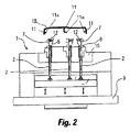
1 to 4 show a part of a
図に示すように、このスライド機構は、(図2の矢印により示されるように)軸方向に上方および下方へ移動可能な可動式エジェクタプレート3に対して垂直に固定されたエジェクタシャフト2と、得ようとする部品10において複製される形状の輪郭を有するスライド部材5とを有し、前記得ようとする部品10は、ネガティブ部11aを備えた下側延長部11を有する。
As shown in the figure, the slide mechanism comprises an
前記エジェクタシャフト2の上端部には、揺動可能なカム6が設けられており、該カム6は、トンネル型のスライド部材5を通って延びるスライド通路14(図5)内でスライド可能である。前記スライド機構はさらに、金型15内に固定されて内部をスライド部材5がスライドするスライド支持部材4(図4)を備え、該スライド支持部材4は、該スライド支持部材4に設けられたガイドブッシング4aの形をした案内通路を通るエジェクタシャフト2により押される。エジェクタシャフト2は、したがって、エジェクタプレート3に垂直な配置を採用し、前記部品10の取り出し移動方向と同じ方向に軸方向が合致している。
A
図3に示すように、カム6は溝部8を有し、該溝部には、円形部の形をした内側第1部8aと、制限タイプの第2部8bと、前記第1部8aとカム6の下側部との間にそれぞれ位置付けられて相互に反対方向に傾斜した側壁を備えた2つの第3部8cとが設けられている。
As shown in FIG. 3, the
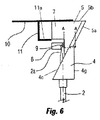
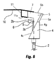
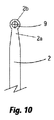
さらに、エジェクタシャフト2(図6,8及び10参照)の自由端には円錐状端部2aが設けられ、該円錐状端部2aの先端には、該端部2aの上部よりも大径で且つカム6の溝部8の内側第1部8aに挿入されることを目的とした突出部2bが設けられている。エジェクタシャフト2とカム6との連結を確実にするために、且つ、それと同時に回転動作可能なように、エジェクタシャフト2の前記自由端において前記突出部2bに形成された空洞の内側に磁石9が収容されている。
Further, the free end of the ejector shaft 2 (see FIGS. 6, 8 and 10) is provided with a
図1及び2に示される実施例では、異なる面を備えた薄層部により構成され、且つ、ネガティブ部11aを備えた3つの下側延長部11を横断方向に突出させる樹脂部品10を製造するために、上述したタイプのスライド機構が3つ設けられている。これにより、各ネガティブ部11aのための本発明の機構は、前記金型の水平面に対して前記部品10が垂直に引き出されることができ、各エジェクタシャフト2がエジェクタプレート3の水平面に対して垂直に移動可能なように、設けられている。
In the embodiment shown in FIGS. 1 and 2, a
図4に示すように、スライド支持部材4は、金型15(図1及び2参照)にスライド支持部材4をねじ留めするのに使用されるねじを受ける機能を有するハウジング4dの形を取り、射出成形金型15にスライド支持部材4を固定するための固定手段と、エジェクタシャフト2が通って延びるガイドブッシング4aと、カム6のためのハウジング部4bと、先端部4gから現れ、射出段階における前進および後退の操作移動中にエジェクタシャフト2により押されたり引かれたりしているときにスライド部材5がスライドする傾斜部4cとを有する。図5においてより明確に示されているように、成形される形状の機械加工を容易にするために、スライド部材5は、単独で機械加工可能で取り出し可能な取り外し可能要素7を収容可能であり、該取り外し可能要素は、スライド部材5のハウジング13内にフィットし、ねじ12によってスライド部材5に固定されている。
As shown in FIG. 4, the
図6及び8は、得ようとする異なる部品10の各実施形態を示す。これらの図において、カム6に設けられた許容差の結果として、ネガティブ部11aの角度に関わらず常に前記シャフト2が水平面に対して垂直に動作する態様が分かり、これにより、前記水平面に対するネガティブ部11aの傾斜角度に適合したカム6の揺動または回転動作の結果として、前記機構1の多用途性が明確に理解され得る。
6 and 8 show embodiments of
図7に示されるように、図4〜6に示すスライド機構1の実施形態において、スライド部材5は、各側面ガイド用凹所5eを有し、該凹所5e内に、スライド支持部材4の各側面ガイド部4fがフィットする。前記ガイド用凹所5eと前記側面ガイド部4fとは傾斜部4cと同じ方向性を有する。さらに、側面ガイド部4fは、スライド支持部材4の先端部4gと同じ高さを有し、これにより、スライド機構1が図2に示す成形位置にあるとき、側面ガイド部4fの上部と、前記先端部4gの前記得ようとする部品への接触領域とが、前記得ようとする部品10の下面に印を残す。
As shown in FIG. 7, in the embodiment of the slide mechanism 1 shown in FIGS. Each side guide
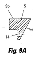
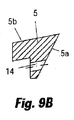
取り出し面に平行な角度を有するネガティブ部の脱型を実現するために、スライド部材において90度(図7,9A)で機械加工されたスライド通路14内をカム6がスライドしなければならないのに対して、90度よりも大きな角度(図8,9C)又は90度よりも小さな角度(図9B)でネガティブ部を脱型するために、成形しようとする部品の部分と同じ角度でスライド部材5に機械加工されたスライド通路14内をカム6がスライドしなければならない。カム6は、前記機械加工された通路に所定の許容差で自動的に適応する。カム6は、前記スライド通路14の内側でのスライドを容易にする潤滑製品で覆われている。
In order to realize demolding of the negative portion having an angle parallel to the take-out surface, the
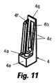
図11は、先端部4gを備えたスライド支持部材4の一実施形態を示し、傾斜部4cと、カム6のためのハウジングとしての役割を果たす中心軸方向溝4bとが前記先端部4gから現れる。前記支持部4の一方の側面に側面ガイド部4fが設けられ、該側面ガイド部4fは、ベース部4eから軸方向に傾斜部4cに平行に延びるが、先端部4gよりも短い長さを有する。ベース部4eには、エジェクタシャフト2が内部でスライドするガイド通路4aが設けられている。
FIG. 11 shows an embodiment of the
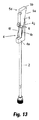
図12は、図11の支持部4に対して相補的なスライド部材5の一実施形態を示す。このスライド部材5は、くさび形であり、ベース部5cから押圧面5bまで延びる傾斜部5aを有し、該傾斜部5aは、支持部4の傾斜部4cと同じ傾斜を有することが見て取れる。比較的低い部分において、スライド部材5は、エジェクタプレート3に向かって開放した溝形のスライド通路14を有するのに対して、比較的高い部分において、スライド部材5は、得ようとする部品10のネガティブ部11aを備えた延長部11に対応する成形部5dを有する。一方の側面において、スライド部材5は、スライド支持部材4の側面ガイド部4fに対して相補的な形態および傾斜を備えたガイド用凹所5eを有する。
FIG. 12 shows an embodiment of the
図13〜16は、図12及び13に示すスライド支持部材4とスライド部材5とを組み込んだスライド機構の一実施形態を示す。この実施形態において、エジェクタシャフト2とカム6とは、図3,6,8及び10においてこれらの要素に関して示される構成と同様の構成を有する。すなわち、エジェクタシャフト2(図6,8及び10参照)の自由端に円錐状の端部2aが設けられ、該円錐状端部2aの先端には、該端部2aの上部よりも大径で且つカム6の溝部8の内側第1部8a(図3参照)に挿入されることを目的とした突出部2bが設けられている。カム6は、スライド部材5におけるスライド通路14内にスライド可能に挿入され、中心軸方向溝4bにも入り込む。図に示すように、スライド部材5の側面は、ガイド用凹所5e内にフィットするスライド支持部材4の側面ガイド部4fと、スライド通路14を通って延び前記軸方向溝4b内を移動可能なカム6との間で案内される。したがって、前記スライド機構が図14に示す成形位置から図16に示す脱型段階まで通るとき、エジェクタシャフト2はカム6を得ようとする部品10に向かって徐々に押し込み、これにより、カム6はスライド支持部材4の傾斜部4cを通してスライド部材5をその傾斜部5aとともに移動させる。この移動において、一方では、前記スライド機構1が割り当てられた前記下側延長部11のネガティブ部11aから成形部5dが離間するようにスライド部材5は側面に向かって移動し、他方では、成形部5dがネガティブ部11aから離間されると、押圧面5bが得ようとする部品10を押し出す。図14に示すように、前記成形位置において、スライド支持部材4の先端部4gの前記自由端は、得ようとする部品10の下面に接しており、それゆえ、該下面に印を残す。それにもかかわらず、図11との関連ですでに述べたように前記スライド支持部材の側面ガイド部4fが先端部4gの高さよりも低い高さを有するという事実に鑑みれば、前記側面ガイド部は得ようとする部品10の下部に印を残さない。
13 to 16 show an embodiment of a slide mechanism in which the
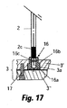
図17〜20は、エジェクタシャフト2を円筒状固定部材16によってエジェクタプレート3に固定する方法の一実施形態を示し、前記固定部材16は、軸方向の止まり穴16aと、外側周辺段部16bと、前記部材16の本体内に配置された非回転ワッシャ16cとを有する。前記周辺段部16bにより、前記固定部材16は、第2円筒部の直径よりも大きな直径を備えた第1円筒部を有する。
FIGS. 17 to 20 show an embodiment of a method of fixing the
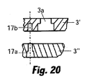
固定プレート3は、貫通穴3aを有する固定プレート3’と、該固定プレート3’にねじ17を用いて締結された底部プレート3”とで構成されている。ねじ留めのために、底部プレート3”には、ねじ17が通過する通路17aがねじ17毎に設けられているのに対して、固定プレート3’は、ねじ17が留められるねじ穴17bを有する。
The fixing
固定部材16は、固定プレート3’の貫通穴3aに挿入されており、該貫通穴3aは、エジェクタプレート3の外側部分における狭窄部と、固定プレート3’の本体内における拡大部とを有する。貫通穴3aのこれらの部分は、固定部材16の前記第1および前記第2の円筒部にそれぞれ対応する大きさを有し、これにより、固定部材16の前記第1円筒部は貫通穴3aの前記狭窄部中に広がる一方、前記第2円筒部は貫通穴3aの前記拡大部中に広がり、前記周辺段部16bは、貫通穴3aの前記狭窄部の縁部に接触して支持される。貫通穴3aの前記拡大部は、底部プレート3”により閉じられており、これにより、固定部材16は、貫通穴3aの前記狭窄部と底部プレート3”との間で軸方向に動かなくなる。
The fixing
非回転ワッシャ16cは、成形工程中にさらされる温度および機械的ストレスに耐性がある合成ゴム又はフッ素重合体エラストマーなどの材料で構成することができる。
The
図17及び18に示すように、エジェクタシャフト2は、固定部材16の非回転ワッシャ16cを備えた止まり穴16aにねじ込まれるねじ山付き端部2cを有する。固定部材16にエジェクタシャフト2をねじ込む前に、前述のねじ山付き端部2cを切除することにより、前記エジェクタシャフトの所望の長さが得られる。固定部材16にねじ山付き端部2cがねじ込まれているとき、非回転ワッシャ16cにより、ねじ山付き端部2cの回転、ひいてはねじの外れを防止する。
As shown in FIGS. 17 and 18, the
図17〜20に示す要素により前記エジェクタシャフトを固定するこの形態では、各エジェクタシャフト2は、径方向の位置(非回転ワッシャ16cの作用により生じる非回転効果)と、軸方向の位置との両方に関して有効に静止される。
In this embodiment in which the ejector shaft is fixed by the elements shown in FIGS. 17 to 20, each
1:スライド機構、2:エジェクタシャフト、3:エジェクタプレート、4:スライド支持部材、5:スライド部材、6:カム(結合要素)、10:被成形部品、11a:ネガティブ部、14:スライド通路。 1: Slide mechanism, 2: Ejector shaft, 3: Ejector plate, 4: Slide support member, 5: Slide member, 6: Cam (coupling element), 10: Part to be molded, 11a: Negative part, 14: Slide passage.
Claims (23)
軸方向の面に沿って移動する可動式エジェクタプレート(3)に取り付けられた第1端部(2c)と、結合要素(6)によりスライド部材(5)に結合された第2端部(2a)と、を備え、前記スライド部材が、該スライド部材(5)を通って延びる被成形部品(10)の少なくとも1つのネガティブ部の形状が備わった成形部(5d)と、ベース部(5c)と、成形中に前記被成形部品(10)に接触する押圧面(5b)と、前記軸方向の面に対する径方向への傾斜部(5a)と、を有する少なくとも1つのエジェクタシャフト(2)と、
前記スライド部材(5)の傾斜部(5a)の傾斜に対して相補的な傾斜を有し、前記スライド部材(5)の傾斜部(5a)が上を移動する傾斜部(4c)と、前記エジェクタシャフト(2)が軸方向にスライドしながら通る軸方向のガイド通路(4a)が設けられたベース部(4e)と、を備えた固定型スライド支持部材(4)と、を備え、
前記スライド部材(5)は、少なくとも部分的に且つ前記ネガティブ部(11a)と平行に前記スライド部材(5)を通って延びるスライド通路(14)を有し、
前記結合要素(6)は、前記エジェクタシャフト(2)の前記第2端部(2a)に取り付けられ、前記スライド通路(14)内に少なくとも部分的にスライド可能にフィットしていることを特徴とするスライド機構。 A slide mechanism for molding and taking out a molded part having a negative portion for an injection mold,
A first end (2c) attached to a movable ejector plate (3) moving along an axial plane, and a second end (2a) coupled to the slide member (5) by a coupling element (6) ), Wherein the slide member has a shape of at least one negative portion of the molded part (10) extending through the slide member (5), and a base portion (5c) And at least one ejector shaft (2) having a pressing surface (5b) that contacts the molded part (10) during molding and a radially inclined portion (5a) with respect to the axial surface. ,
An inclined portion (4c) having an inclination complementary to the inclination of the inclined portion (5a) of the slide member (5), and the inclined portion (5a) of the slide member (5) moving above, A fixed slide support member (4) provided with a base portion (4e) provided with an axial guide passage (4a) through which the ejector shaft (2) slides in the axial direction;
The slide member (5) has a slide passage (14) extending through the slide member (5) at least partially and parallel to the negative portion (11a);
The coupling element (6) is attached to the second end (2a) of the ejector shaft (2) and is slidably fitted into the slide passage (14) at least partially. Slide mechanism.
前記エジェクタシャフト(2)の前記第2端部(2a)は、前記カム(6)に結合された突出部(2b)で終結し、
該突出部(2b)は、前記カム(6)を揺動可能に支持する回転シャフトの役割を果たすものであることを特徴とする請求項1に記載のスライド機構。 The coupling element (6) is a cam;
The second end (2a) of the ejector shaft (2) terminates in a protrusion (2b) coupled to the cam (6),
The slide mechanism according to claim 1, wherein the projecting portion (2b) serves as a rotating shaft that supports the cam (6) so as to be swingable.
前記突出部(2b)は、該突出部(2a)において前記カム(6)が揺動可能なように前記カム(6)の前記溝部(8)の前記第1部(8a)内に収容されていることを特徴とする請求項2〜5のいずれか1項に記載のスライド機構。 The cam (6) includes an inner first portion (8a) having a circular portion in which the protruding portion (2a) of the ejector shaft (2) is accommodated, a restriction-type intermediate portion (8b), and the intermediate portion A groove portion (8) provided with an outer third portion (8c) having an opposing side wall inclined while converging toward (8b),
The protrusion (2b) is accommodated in the first part (8a) of the groove (8) of the cam (6) so that the cam (6) can swing at the protrusion (2a). The slide mechanism according to any one of claims 2 to 5, wherein the slide mechanism is provided.
該側面ガイド部(4f)と前記ガイド用凹所(5e)とは、前記スライド支持部材(4)の傾斜部(4c)と同じ方向性を有することを特徴とする請求項1〜15のいずれか1項に記載のスライド機構。 The slide support member includes at least one side guide portion (4f) that enters the guide recess (5e) of the slide member (5),
The side surface guide portion (4f) and the guide recess (5e) have the same directionality as the inclined portion (4c) of the slide support member (4). The slide mechanism according to claim 1.
前記固定部材(16)は円筒状であり、第1部と、第2部と、前記第1部と前記第2部との間の周辺段部(16b)とを備え、前記第1部は前記第2部よりも小さな直径を有し、
前記固定プレート(3’)における前記穴(3a)は、前記固定プレート(3’)の外側部分における狭窄部と固定プレート(3’)の本体内における拡大部とを備えた貫通穴であり、該貫通穴(3a)の前記狭窄部と前記拡大部とは、前記固定部材(16)の前記第1円筒状部および前記第2円筒状部にそれぞれ対応する大きさを有し、これにより、前記固定部材(16)の前記第1円筒状部は、前記貫通穴(3a)の前記狭窄部に収容され、前記第2円筒状部は、前記貫通穴(3a)の前記拡大部に挿入され、前記周辺段部(16b)は、前記貫通穴(3a)の前記狭窄部の縁部に接触して支持され、
前記底部プレート(3”)は、前記固定プレート(3’)における前記貫通穴(3a)の前記拡大部を閉じていることを特徴とする請求項19に記載のスライド機構。 The ejector plate (3) comprises a fixed plate (3 ′) with the complementary holes (3a) attached to each other, and a bottom plate (3 ″),
The fixing member (16) has a cylindrical shape, and includes a first part, a second part, and a peripheral step part (16b) between the first part and the second part. Having a smaller diameter than the second part;
The hole (3a) in the fixed plate (3 ′) is a through hole provided with a narrowed portion in an outer portion of the fixed plate (3 ′) and an enlarged portion in the main body of the fixed plate (3 ′), The narrowed portion and the enlarged portion of the through hole (3a) have sizes corresponding to the first cylindrical portion and the second cylindrical portion of the fixing member (16), respectively. The first cylindrical portion of the fixing member (16) is accommodated in the narrowed portion of the through hole (3a), and the second cylindrical portion is inserted into the enlarged portion of the through hole (3a). The peripheral step (16b) is supported in contact with the edge of the narrowed portion of the through hole (3a),
The slide mechanism according to claim 19, wherein the bottom plate (3 ") closes the enlarged portion of the through hole (3a) in the fixed plate (3 ').
Applications Claiming Priority (3)
| Application Number | Priority Date | Filing Date | Title |
|---|---|---|---|
| ESP200803363 | 2008-11-26 | ||
| ES200803363A ES2365570B1 (en) | 2008-11-26 | 2008-11-26 | SLIDING MECHANISM FOR MOLDING AND EXPULSION OF NEGATIVES IN PLASTIC INJECTION MOLDS |
| PCT/ES2009/070524 WO2010061026A2 (en) | 2008-11-26 | 2009-11-24 | Slide mechanism for the moulding and ejection of parts moulded with negatives for an injection mould |
Publications (2)
| Publication Number | Publication Date |
|---|---|
| JP2012509781A true JP2012509781A (en) | 2012-04-26 |
| JP5640012B2 JP5640012B2 (en) | 2014-12-10 |
Family
ID=42226167
Family Applications (1)
| Application Number | Title | Priority Date | Filing Date |
|---|---|---|---|
| JP2011536910A Expired - Fee Related JP5640012B2 (en) | 2008-11-26 | 2009-11-24 | Slide mechanism for molding and taking out molded part with negative part for injection mold |
Country Status (5)
| Country | Link |
|---|---|
| US (1) | US8469696B2 (en) |
| EP (1) | EP2351640A4 (en) |
| JP (1) | JP5640012B2 (en) |
| ES (1) | ES2365570B1 (en) |
| WO (1) | WO2010061026A2 (en) |
Families Citing this family (20)
| Publication number | Priority date | Publication date | Assignee | Title |
|---|---|---|---|---|
| ES2345697B1 (en) * | 2007-12-31 | 2011-09-28 | Jose Luis Gonzalez Palacio Fenech | DEVICE FOR THE DISMOLDING OF NEGATIVES IN PLASTIC INJECTION. |
| US8475156B2 (en) * | 2011-03-24 | 2013-07-02 | Cheng Uei Precision Industry Co., Ltd. | Injection mold |
| US8758007B2 (en) * | 2012-02-08 | 2014-06-24 | Shin Tai Plastics Industrial Co., Ltd. | Structure of slide-block module of a plastic pallet shaping mold |
| ES2398793B1 (en) * | 2012-11-27 | 2014-02-10 | Comercial de Útiles y Moldes, S.A. | Parts demoulding device |
| ES2428238B1 (en) * | 2013-06-25 | 2014-09-02 | Comercial de Útiles y Moldes, S.A. | Parts demoulding device |
| DE102013018968A1 (en) * | 2013-11-07 | 2015-05-07 | Pauser und Weinkauf Vertriebs GmbH | injection mold |
| US9028244B1 (en) | 2013-12-06 | 2015-05-12 | Fca Us Llc | Lifter for an injection molding tool |
| TW201615379A (en) * | 2014-10-17 | 2016-05-01 | 綠點高新科技股份有限公司 | Injection molding method and mold mechanism |
| US10226886B2 (en) * | 2015-01-27 | 2019-03-12 | Samsung Electronics Co., Ltd. | Slim injection molding apparatus |
| KR200486819Y1 (en) * | 2016-10-25 | 2018-07-03 | 주식회사 대부 | Mold frame structure |
| JP6836774B2 (en) * | 2016-11-28 | 2021-03-03 | 株式会社テクノクラーツ | Undercut processing mechanism, molding mold |
| CN109093955B (en) * | 2018-10-09 | 2023-07-18 | 深圳市合川智能科技有限公司 | Mold with three-time ejection mechanism and ejection method thereof |
| EP3708332B1 (en) * | 2019-03-13 | 2022-11-09 | Comercial de Utiles y Moldes, S.A. | Device for demoulding negatives in thermoplastic injection moulds |
| CN110076318A (en) * | 2019-05-26 | 2019-08-02 | 深圳市宝田精工塑胶模具有限公司 | Kirsite molding die |
| CN110303650B (en) * | 2019-06-27 | 2024-02-23 | 常州星宇车灯股份有限公司 | Mould secondary ejection frock |
| CN113815194B (en) * | 2021-10-09 | 2023-09-26 | 广东东亚电器有限公司 | A mould for having injection moulding product shaping of back-off to one side |
| CN114055734B (en) * | 2022-01-18 | 2022-04-12 | 宁海县第一注塑模具有限公司 | Injection mold for automobile structural part |
| CN115071007B (en) * | 2022-07-18 | 2023-07-25 | 富诚汽车零部件有限公司 | Core pulling structure for central channel cladding decoration product |
| CN116461049A (en) * | 2023-05-08 | 2023-07-21 | 深圳恒佳精密模具注塑有限公司 | Circulating type anti-leakage double-color injection mold |
| CN117001899B (en) * | 2023-09-07 | 2024-02-06 | 西安驰达飞机零部件制造股份有限公司 | Demolding device for processing aircraft composite material |
Citations (8)
| Publication number | Priority date | Publication date | Assignee | Title |
|---|---|---|---|---|
| JPH03129429U (en) * | 1990-04-10 | 1991-12-26 | ||
| JP2002120262A (en) * | 2000-10-16 | 2002-04-23 | Nissan Motor Co Ltd | Injection mold |
| JP2002127204A (en) * | 2000-10-27 | 2002-05-08 | Sekisui Chem Co Ltd | Mold for injection molding |
| JP3974641B1 (en) * | 2006-08-29 | 2007-09-12 | 株式会社テクノクラーツ | Mold equipment for molding |
| JP3974643B1 (en) * | 2006-11-30 | 2007-09-12 | 株式会社テクノクラーツ | Undercut processing mechanism |
| JP3974642B1 (en) * | 2006-08-29 | 2007-09-12 | 株式会社テクノクラーツ | Mold equipment for molding |
| JP2009126121A (en) * | 2007-11-27 | 2009-06-11 | Technocrats Corp | Undercutting mechanism |
| JP2010083033A (en) * | 2008-09-30 | 2010-04-15 | Technocrats Corp | Undercut processing mechanism |
Family Cites Families (41)
| Publication number | Priority date | Publication date | Assignee | Title |
|---|---|---|---|---|
| US548895A (en) * | 1895-10-29 | Willard g | ||
| US2529091A (en) * | 1946-10-05 | 1950-11-07 | William M Lester | Mold for a plastic ring having an annulus and a motif |
| US3865529A (en) * | 1973-12-05 | 1975-02-11 | Beatrice Foods Co | Molding apparatus |
| US4101256A (en) * | 1977-03-11 | 1978-07-18 | E & E Specialties, Inc. | Mold for forming a plastic article having an undercut or negative draft portion |
| JPS5937215B2 (en) * | 1981-11-17 | 1984-09-08 | ホンダエンジニアリング株式会社 | Synthetic resin mold |
| JPS58134726A (en) * | 1982-02-05 | 1983-08-11 | Nissan Motor Co Ltd | Mold for injection molding |
| US4515342A (en) * | 1984-04-06 | 1985-05-07 | Borislav Boskovic | Slide retainer |
| US4832307A (en) * | 1988-09-15 | 1989-05-23 | Toshiba Kikai Kabushiki Kaisha | Injection mold |
| JPH04189521A (en) * | 1990-11-26 | 1992-07-08 | Daikyo Inc | Plastic forming mold structure |
| US5281127A (en) * | 1992-05-14 | 1994-01-25 | Ramsey William C | Articulated core blade assembly for use in an injection molding machine |
| JP2812198B2 (en) * | 1994-04-28 | 1998-10-22 | 豊田合成株式会社 | Method for manufacturing steering wheel pad |
| US5551864A (en) * | 1995-01-12 | 1996-09-03 | Boskovic; Borislav | Core lifter system |
| DE19507009C2 (en) * | 1995-02-28 | 1997-03-13 | Johannes Ludwig Foellmer | Device for demoulding injection molded parts |
| US5773048A (en) * | 1995-08-07 | 1998-06-30 | Ramsey; William C. | Retainer for injection molding machine components |
| JP3259644B2 (en) * | 1996-10-11 | 2002-02-25 | 豊田合成株式会社 | Mold for steering wheel molding |
| US5814357A (en) * | 1997-08-15 | 1998-09-29 | Boskovic; Borislav | Core lifter system for use in a plastic injection mold |
| JP2983510B2 (en) * | 1997-09-29 | 1999-11-29 | 三星電子株式会社 | Plastic injection molds |
| CA2260681C (en) * | 1999-02-02 | 2007-04-10 | Top Grade Molds Ltd. | Mold collet lifting ring |
| EP1092521B1 (en) * | 1999-08-20 | 2003-08-20 | Erwin Wimmer | Mould for injection or pressure moulding machine |
| US6604934B2 (en) * | 1999-12-08 | 2003-08-12 | Top Grade Molds Ltd. | Dual stage floating ring mold ejection |
| US6491513B1 (en) * | 2000-07-20 | 2002-12-10 | Omni Mold Systems | Internal core lifter and a mold incorporating the same |
| ES2170702A1 (en) * | 2000-10-25 | 2002-08-01 | Pruna Alberto Navarra | Flexible ejector for injection molds |
| ES2220158B1 (en) | 2001-10-29 | 2005-12-16 | Alberto Navarra Pruna | EXPULSION MECHANISM FOR INJECTION MOLDS. |
| DE10231551A1 (en) * | 2002-07-11 | 2004-01-22 | Balda Werkzeug- Und Vorrichtungsbau Gmbh | Molding tool for plastic housing parts |
| JP4088568B2 (en) * | 2003-08-18 | 2008-05-21 | 株式会社 タカオ設計事務所 | Ejector device |
| ES2219196B1 (en) | 2004-04-28 | 2005-09-16 | Comercial De Utiles Y Moldes, S.A. | SLIDING MECHANISM FOR MOLDING AND EXPULSION OF NEGATIVES IN INJECTION MOLDS. |
| JP4458473B2 (en) * | 2004-09-28 | 2010-04-28 | 株式会社小糸製作所 | Method for forming vehicle lamp part and apparatus for forming vehicle lamp part |
| DE102005011311B3 (en) * | 2005-03-08 | 2006-05-11 | Schneider Form Gmbh | Injection molding tool for forming undercut moldings has retractable slide connected to retacting guide so that slide moves along the axes of demolding guide and retraction guide |
| US7559763B2 (en) * | 2005-06-20 | 2009-07-14 | Crest Mold Technology Inc. | Dual material injection mold and method |
| US7435079B2 (en) * | 2006-04-18 | 2008-10-14 | Cheng Uei Precision Industry Co., Ltd. | Angular ejector mechanism and injection mold with the same |
| FR2900351B1 (en) * | 2006-04-26 | 2008-06-13 | Commissariat Energie Atomique | PROCESS FOR PREPARING A NANOPOROUS LAYER OF NANOPARTICLES AND THE LAYER THUS OBTAINED |
| US7387505B1 (en) * | 2006-11-24 | 2008-06-17 | Cheng Uei Precision Industry Co., Ltd. | Side-action mechanism and injection mold using the same |
| JP3133912U (en) * | 2007-05-17 | 2007-07-26 | 株式会社 タカオ設計事務所 | Ejector device |
| US7481648B1 (en) * | 2007-11-16 | 2009-01-27 | Cheng Uei Precision Industry Co., Ltd. | Side mold working mechanism |
| ES2345697B1 (en) * | 2007-12-31 | 2011-09-28 | Jose Luis Gonzalez Palacio Fenech | DEVICE FOR THE DISMOLDING OF NEGATIVES IN PLASTIC INJECTION. |
| CN101733905A (en) * | 2008-11-14 | 2010-06-16 | 群康科技(深圳)有限公司 | Injection mold |
| TWI409157B (en) * | 2009-04-30 | 2013-09-21 | Pegatron Corp | Injection mold |
| US20110262583A1 (en) * | 2010-04-26 | 2011-10-27 | Vp Components Co., Ltd. | Mould with demoulding function |
| US8142185B1 (en) * | 2010-09-30 | 2012-03-27 | Cheng Uei Precision Industry Co., Ltd. | Injection mold forming a product having a barbed structure |
| US8197246B1 (en) * | 2010-12-03 | 2012-06-12 | Cheng Uei Precision Industry Co., Ltd. | Plastic injection mold |
| US20120183641A1 (en) * | 2011-01-18 | 2012-07-19 | Tpv Display Technology (Xiamen) Co., Ltd. | Mold releasing device |
-
2008
- 2008-11-26 ES ES200803363A patent/ES2365570B1/en not_active Expired - Fee Related
-
2009
- 2009-11-24 WO PCT/ES2009/070524 patent/WO2010061026A2/en active Application Filing
- 2009-11-24 JP JP2011536910A patent/JP5640012B2/en not_active Expired - Fee Related
- 2009-11-24 EP EP09828671A patent/EP2351640A4/en not_active Withdrawn
- 2009-11-24 US US12/920,536 patent/US8469696B2/en active Active
Patent Citations (8)
| Publication number | Priority date | Publication date | Assignee | Title |
|---|---|---|---|---|
| JPH03129429U (en) * | 1990-04-10 | 1991-12-26 | ||
| JP2002120262A (en) * | 2000-10-16 | 2002-04-23 | Nissan Motor Co Ltd | Injection mold |
| JP2002127204A (en) * | 2000-10-27 | 2002-05-08 | Sekisui Chem Co Ltd | Mold for injection molding |
| JP3974641B1 (en) * | 2006-08-29 | 2007-09-12 | 株式会社テクノクラーツ | Mold equipment for molding |
| JP3974642B1 (en) * | 2006-08-29 | 2007-09-12 | 株式会社テクノクラーツ | Mold equipment for molding |
| JP3974643B1 (en) * | 2006-11-30 | 2007-09-12 | 株式会社テクノクラーツ | Undercut processing mechanism |
| JP2009126121A (en) * | 2007-11-27 | 2009-06-11 | Technocrats Corp | Undercutting mechanism |
| JP2010083033A (en) * | 2008-09-30 | 2010-04-15 | Technocrats Corp | Undercut processing mechanism |
Also Published As
| Publication number | Publication date |
|---|---|
| ES2365570A1 (en) | 2011-10-07 |
| EP2351640A2 (en) | 2011-08-03 |
| WO2010061026A2 (en) | 2010-06-03 |
| EP2351640A4 (en) | 2013-01-02 |
| US20110003027A1 (en) | 2011-01-06 |
| ES2365570B1 (en) | 2012-09-17 |
| WO2010061026A3 (en) | 2010-07-22 |
| JP5640012B2 (en) | 2014-12-10 |
| US8469696B2 (en) | 2013-06-25 |
Similar Documents
| Publication | Publication Date | Title |
|---|---|---|
| JP5640012B2 (en) | Slide mechanism for molding and taking out molded part with negative part for injection mold | |
| US8657599B2 (en) | Device for demoulding negatives in plastic injection | |
| CN106827396A (en) | A kind of automobile audio panel injection mold | |
| CN204701086U (en) | A kind of two-step ejecting mold mechanism | |
| CN110625901A (en) | Slide secondary core-pulling structure | |
| JP2013000774A (en) | Clamping device of injection molding machine | |
| JP2016007625A (en) | Die casting device | |
| JP2003231160A (en) | Mold for injection molding machine | |
| CN218876153U (en) | Injection mold gets a device | |
| CN111452302A (en) | Injection molding mechanical mold capable of being positioned quickly | |
| CN108162335B (en) | Deep rib large-angle demoulding mechanism for inclined plane of automobile decorative plate support | |
| JP4095093B2 (en) | Injection mold | |
| CN220052644U (en) | Controller shell injection mold | |
| CN220280377U (en) | Hole processing device and die | |
| CN212400237U (en) | Demoulding mechanism and injection mold | |
| JPH0132762B2 (en) | ||
| KR20190044035A (en) | Die-casting mold contains upper ejecting structure for deformation prevention of molded product | |
| CN104842535B (en) | Injection molding processing method for forming orthogonal through micro-hole | |
| CN111571941B (en) | Injection mold | |
| CN211389913U (en) | Injection mold with side opening of lamp surface ring | |
| CN220314067U (en) | Mould with oblique ejector pin structure | |
| JP2686552B2 (en) | Mold | |
| CN209407179U (en) | A kind of automobile interior top plate processing mold with pull rod | |
| CN115416233B (en) | Injection mold is used in production of hemisphere work piece | |
| CN214266533U (en) | Mold inclined ejection mechanism and injection mold |
Legal Events
| Date | Code | Title | Description |
|---|---|---|---|
| A621 | Written request for application examination |
Free format text: JAPANESE INTERMEDIATE CODE: A621 Effective date: 20121003 |
|
| A977 | Report on retrieval |
Free format text: JAPANESE INTERMEDIATE CODE: A971007 Effective date: 20131009 |
|
| A131 | Notification of reasons for refusal |
Free format text: JAPANESE INTERMEDIATE CODE: A131 Effective date: 20131022 |
|
| A521 | Request for written amendment filed |
Free format text: JAPANESE INTERMEDIATE CODE: A523 Effective date: 20140121 |
|
| A521 | Request for written amendment filed |
Free format text: JAPANESE INTERMEDIATE CODE: A523 Effective date: 20140122 |
|
| A131 | Notification of reasons for refusal |
Free format text: JAPANESE INTERMEDIATE CODE: A131 Effective date: 20140819 |
|
| A521 | Request for written amendment filed |
Free format text: JAPANESE INTERMEDIATE CODE: A523 Effective date: 20140825 |
|
| TRDD | Decision of grant or rejection written | ||
| A01 | Written decision to grant a patent or to grant a registration (utility model) |
Free format text: JAPANESE INTERMEDIATE CODE: A01 Effective date: 20141014 |
|
| A61 | First payment of annual fees (during grant procedure) |
Free format text: JAPANESE INTERMEDIATE CODE: A61 Effective date: 20141027 |
|
| R150 | Certificate of patent or registration of utility model |
Ref document number: 5640012 Country of ref document: JP Free format text: JAPANESE INTERMEDIATE CODE: R150 |
|
| R250 | Receipt of annual fees |
Free format text: JAPANESE INTERMEDIATE CODE: R250 |
|
| R250 | Receipt of annual fees |
Free format text: JAPANESE INTERMEDIATE CODE: R250 |
|
| R250 | Receipt of annual fees |
Free format text: JAPANESE INTERMEDIATE CODE: R250 |
|
| R250 | Receipt of annual fees |
Free format text: JAPANESE INTERMEDIATE CODE: R250 |
|
| LAPS | Cancellation because of no payment of annual fees |