JP2012509157A - Intramedullary repair system for vertebral fractures - Google Patents
Intramedullary repair system for vertebral fractures Download PDFInfo
- Publication number
- JP2012509157A JP2012509157A JP2011537630A JP2011537630A JP2012509157A JP 2012509157 A JP2012509157 A JP 2012509157A JP 2011537630 A JP2011537630 A JP 2011537630A JP 2011537630 A JP2011537630 A JP 2011537630A JP 2012509157 A JP2012509157 A JP 2012509157A
- Authority
- JP
- Japan
- Prior art keywords
- implant
- fracture
- vertebral
- vertebral body
- incremental
- Prior art date
- Legal status (The legal status is an assumption and is not a legal conclusion. Google has not performed a legal analysis and makes no representation as to the accuracy of the status listed.)
- Withdrawn
Links
Images


Classifications
-
- A—HUMAN NECESSITIES
- A61—MEDICAL OR VETERINARY SCIENCE; HYGIENE
- A61B—DIAGNOSIS; SURGERY; IDENTIFICATION
- A61B17/00—Surgical instruments, devices or methods, e.g. tourniquets
- A61B17/56—Surgical instruments or methods for treatment of bones or joints; Devices specially adapted therefor
- A61B17/58—Surgical instruments or methods for treatment of bones or joints; Devices specially adapted therefor for osteosynthesis, e.g. bone plates, screws, setting implements or the like
- A61B17/68—Internal fixation devices, including fasteners and spinal fixators, even if a part thereof projects from the skin
- A61B17/70—Spinal positioners or stabilisers ; Bone stabilisers comprising fluid filler in an implant
- A61B17/7094—Solid vertebral fillers; devices for inserting such fillers
- A61B17/7095—Solid vertebral fillers; devices for inserting such fillers the filler comprising unlinked macroscopic particles
-
- A—HUMAN NECESSITIES
- A61—MEDICAL OR VETERINARY SCIENCE; HYGIENE
- A61B—DIAGNOSIS; SURGERY; IDENTIFICATION
- A61B17/00—Surgical instruments, devices or methods, e.g. tourniquets
- A61B17/56—Surgical instruments or methods for treatment of bones or joints; Devices specially adapted therefor
- A61B17/58—Surgical instruments or methods for treatment of bones or joints; Devices specially adapted therefor for osteosynthesis, e.g. bone plates, screws, setting implements or the like
- A61B17/88—Osteosynthesis instruments; Methods or means for implanting or extracting internal or external fixation devices
- A61B17/885—Tools for expanding or compacting bones or discs or cavities therein
- A61B17/8852—Tools for expanding or compacting bones or discs or cavities therein capable of being assembled or enlarged, or changing shape, inside the bone or disc
Abstract
椎体の骨折部を整復するシステムが開示されている。このシステムは、少量ずつ送給されて蓄積される複数のインクリメンタル・インプラント要素(以下、「複数の要素])と、送給デバイスとを含む。複数の要素は、椎体の内部空間内への経皮的な送給および椎体の内部空間内での蓄積が可能であるように構成されている。送給デバイスは、複数の要素を、椎体の内部空間内に経皮的に、かつ、少量ずつ送給するインクリメンタル方式で送給するように構成されている。複数の要素は、少量ずつ椎体の内部空間内に送給されるため、複数の要素が椎体の内部空間内に蓄積され、それにより、椎体の骨折部が整復される。
【選択図】図1AA system for reducing a fracture of a vertebral body is disclosed. The system includes a plurality of incremental implant elements (hereinafter “multiple elements”) that are delivered and stored in small quantities, and a delivery device, wherein the elements are within the interior space of the vertebral body. The device is configured to allow percutaneous delivery and accumulation within the interior space of the vertebral body, wherein the delivery device includes a plurality of elements percutaneously within the interior space of the vertebral body, and The multiple elements are fed into the interior space of the vertebral body in small quantities, so that the multiple elements are fed into the interior space of the vertebral body. Accumulate, thereby reducing the fracture of the vertebral body.
[Selection] Figure 1A
Description
本出願は、米国特許法第119条に従い、米国仮特許出願第61/116,074号の優先権を主張しており、その出願は、2008年11月19日に出願されるとともに、引用により全体的に本出願に合体する。 This application claims priority to US Provisional Patent Application No. 61 / 116,074 in accordance with Section 119 of the US Patent Act, which application was filed on November 19, 2008, and is incorporated by reference. All incorporated into this application.
本出願は、さらに、同時に係属している米国特許出願第12/622,320号(米国特許出願公開公報第2010/0137987号)に関連しており、その出願は、2009年11月19日に出願され、かつ、発明の名称が「椎骨骨折部用髄内修復システム」であるとともに、引用により全体的に本出願に合体する。 This application is further related to co-pending U.S. Patent Application No. 12 / 622,320 (U.S. Patent Application Publication No. 2010/0137987), which was filed on November 19, 2009. It is filed and the name of the invention is “intramedullary repair system for vertebral fractures” and is incorporated herein by reference in its entirety.
本発明は、整形外科用の装置および方法に関する。具体的に言えば、本発明は、髄内において椎骨骨折部を修復するデバイスおよび方法に関する。 The present invention relates to orthopedic devices and methods. Specifically, the present invention relates to devices and methods for repairing vertebral fractures in the medulla.
いくらよく見ても、椎骨骨折部の治療を成功裏に行うことはこれまで困難であった。例えば、その椎骨骨折部が、外科的手術の段階および術後治療の段階において、完全に整復された状態に維持されず、再手術を必要とすることは希ではない。その治療された椎骨骨折部は、期待通りの強度を有しない可能性がある。また、患者の軟部組織の損傷が大きく、患者の痛みが増して、治癒に必要な期間が長期化する可能性もある。結局、外科的手術を複数回行うこと(surgical procedure times)が重要であり得る。 At best, it has been difficult to treat vertebral fractures successfully. For example, it is not uncommon for the vertebral fracture to remain fully reduced and require re-operation during the surgical and post-operative treatment stages. The treated vertebral fracture may not have the expected strength. In addition, the patient's soft tissue can be severely damaged, increasing patient pain and prolonging the time required for healing. Eventually, surgical procedure times may be important.
当業界においては、椎骨骨折部の治療実績を向上させ、その結果、骨折部が良好に整列するとともに回復後の骨折部の強度が向上し、再手術が必要となる可能性を低下させ、そして、骨折部に隣接する軟部組織の損傷が軽減されることを可能にするデバイスおよび方法が要望される。さらに、当業界においては、骨折部の治療に必要な外科的手術回数(surgical time)を削減するデバイスおよび方法も要望される。 In the industry, improve the performance of treatment of vertebral fractures, resulting in better alignment of fractures and increased strength of fractures after recovery, reducing the possibility of needing re-operation; and There is a need for devices and methods that allow soft tissue damage adjacent to the fracture to be reduced. In addition, there is a need in the art for devices and methods that reduce the surgical time required to treat fractures.
本明細書には、椎体における骨折部を整復する椎体骨折部整復システムが開示されている。一実施形態においては、この椎体骨折部整復システムが、増分ずつ送給されて蓄積される複数のインクリメンタル・インプラント要素と、送給(delivery、挿入)デバイスとを含む。前記複数のインクリメンタル・インプラント要素は、前記椎体の内部空間内への経皮的な送給(挿入)および前記椎体の内部空間内での蓄積(accumulation、集積、堆積)が可能であるように構成されている。前記送給デバイスは、前記複数のインクリメンタル・インプラント要素を、前記椎体の内部空間内に、経皮的に、かつ、増分ずつ送給するインクリメンタル方式で(増分的に、少量ずつ順次)送給するように構成されている。 The present specification discloses a vertebral body fracture reduction system that reduces a fracture part in a vertebral body. In one embodiment, the vertebral fracture reduction system includes a plurality of incremental implant elements that are delivered and stored incrementally and a delivery device. The plurality of incremental implant elements are capable of transcutaneous delivery (insertion) into the interior space of the vertebral body and accumulation (accumulation, accumulation, deposition) within the interior space of the vertebral body. It is configured. The delivery device delivers the plurality of incremental implant elements into the interior space of the vertebral body percutaneously and incrementally (incrementally, in small increments). Is configured to do.
本明細書には、椎体における骨折部を整復する椎体骨折部整復用髄内インプラントが開示されている。一実施形態においては、この椎体骨折部整復用髄内インプラントが、概して互いに対向する複数枚のプレートを含み、それらプレートは、互いに連結されるとともに、経皮的に送給可能な経皮的送給可能状態(挿入可能状態)から、前記複数枚のプレートが互いに離れる向きに変位する展開状態(deployed configuration)まで展開するように構成されている。 The present specification discloses an intramedullary implant for reducing vertebral fractures that reduces fractures in the vertebral bodies. In one embodiment, the intramedullary implant for vertebral fracture reduction includes a plurality of plates generally facing each other, the plates being connected to each other and transcutaneously deliverable. It is configured to expand from a feedable state (insertable state) to a deployed state in which the plurality of plates are displaced away from each other.
本明細書には、椎体(椎骨)における骨折部を整復する椎体骨折部整復方法が開示されている。一実施形態においては、この椎体骨折部整復方法が、インプラントを前記椎体の内部空間内に経皮的に挿入する挿入工程と、前記インプラントのうちの第1部材および第2部材を前記椎体の内部空間内において互いに離れる向きに変位させ、それにより、前記椎体における前記骨折部を整復状態に移行させる変位工程と、前記椎体における前記骨折部が前記整復状態に維持されるように、前記第1および第2部材を相対的に固定する固定工程とを含む。 The present specification discloses a vertebral body fracture reduction method for reducing a fracture part in a vertebral body (vertebra). In one embodiment, this vertebral body fracture reduction method includes an insertion step of percutaneously inserting an implant into an internal space of the vertebral body, and a first member and a second member of the implant are inserted into the vertebra. Displacement in a direction away from each other in the internal space of the body, thereby shifting the fractured portion in the vertebral body to a reduced state, and so that the fractured portion in the vertebral body is maintained in the reduced state And a fixing step of relatively fixing the first and second members.
本明細書には、椎体(椎骨)における骨折部を整復する別の椎体骨折部整復方法も開示されている。一実施形態においては、この椎体骨折部整復方法が、複数のインクリメンタル・インプラント要素を前記椎体の内部空間内に経皮的に挿入する挿入工程を含み、前記複数のインクリメンタル・インプラント要素が前記椎体の内部空間内に蓄積されると、前記椎体における前記骨折部が整復状態に移行する。 The present specification also discloses another vertebral body fracture reduction method for reducing a fracture part in a vertebral body (vertebra). In one embodiment, the vertebral fracture reduction method includes an insertion step of percutaneously inserting a plurality of incremental implant elements into the interior space of the vertebral body, the plurality of incremental implant elements being When accumulated in the internal space of the vertebral body, the fracture in the vertebral body transitions to a reduced state.
複数の実施形態が開示されているが、当業者であれば、後述の「発明を実施するための形態」の欄であって、本発明の例示的ないくつかの実施形態を図面および文章によって説明する欄の記載から、本発明のさらに別のいくつかの実施形態が存在することが明らかとなるであろう。後に理解されるように、本発明は、種々の観点からのいくつかの変更点を、それら変更点のいずれについても、本発明の主旨からも範囲からも逸脱することなく、加えることが可能である。したがって、図面および「発明を実施するための形態」の記載は、限定的なものではなく、そもそも例示的なものとして認識すべきである。 A plurality of embodiments have been disclosed. However, those skilled in the art will understand several exemplary embodiments of the present invention by referring to the drawings and text in the “Mode for Carrying Out the Invention” section below. From the description in the description section, it will become apparent that there are still some other embodiments of the present invention. As will be understood later, the present invention is capable of making several changes from various points of view, without any departure from the spirit and scope of the invention. is there. Accordingly, the drawings and description of the detailed description are to be regarded as illustrative in nature and not restrictive.
本明細書には、椎骨(椎体)の骨折部を整復するために髄内において使用されるインプラント(移植具)10が開示されている。いくつかの実施形態においては、インプラント10が、最小侵襲手術MIS(最小限の観血的手術)により(例えば、経皮的に)、かつ、完成品として(すべての部品を備えた状態で)、椎体の髄内に位置する内部空間内に送給(挿入)される。いくつかの別の実施形態においては、インプラント10が、部分的にまたは完全に分解された状態で最小侵襲的に送給され、その後、椎体の髄内に位置する内部空間内において組み立てられる。いくつかのさらに別の実施形態においては、インプラント10が、椎体の髄内に位置する内部空間内に最小侵襲的に、かつ、少量の増分ずつ順次送給されて蓄積される複数のインクリメンタル・インプラント要素を有する。それらインクリメンタル・インプラント要素が生体内に蓄積されるかまたは生体内において組み立てられることにより、インプラント10が形成され、骨折部を整復するように作用する。それら実施形態のいずれにおいても、インプラント10が、椎体の髄内に位置する内部空間内に位置する内部の骨に対抗する(骨を押す)ように作用し、それにより、椎体を、損傷前(骨折前)の状態と概して等しい状態に整復する。
The present specification discloses an
インプラント10ならびにそれの送給のための送給システムおよび送給方法は、多くの理由によって有利である。第1に、インプラント10を送給するのに最小侵襲的な手法が採用されるため、患者の不快感も軟部組織の損傷も最小限に抑えられる。インプラント10は、髄内に設置されるため、荷重遮断型(load-shielding)ではなく、荷重共有型(load-sharing)のデバイスであり、それにより、骨折部が治療された後のその骨の再造形作用が促進されることになるとともに、その骨組織の強度が長期間、良好に維持されることになる。また、インプラント10は髄内に設置されるため、インプラント10を使用した結果、軟部組織に炎症が発生してしまうことがなく、また、再手術が必要となる可能性が低い。インプラント10が種々の構成・態様を取り得るということを部分的な理由として、インプラント10は、骨折の位置および重症度に関する広範な種類の椎骨骨折部に非常によく適応可能である。インプラント10の構成、配置・展開および最小侵襲性により、椎骨骨折部の修復に必要な外科的な工程数が、当業界において知られているプレート、ゲージまたは他のデバイスを用いて同じ椎骨骨折部を修復する場合と比較して、約50%削減される可能性があり、これにより、外科的手術回数(手術時間)および費用が節約され、さらに、患者に対して長期にわたって何回も処置を施すことのリスクが低減する。最後に、インプラント10は、種々の実施形態において、椎体を整復状態に積極的に維持するとともに、椎体内に留置されるため、その椎体は、外科的処置の全期間中およびそれに後続する治療の期間中、整復状態に維持され、それにより、当業界におけるこれまでの効果より優れた効果を奏する。
The
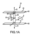
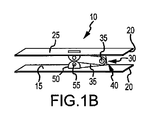
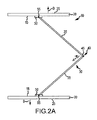
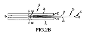
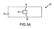
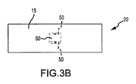
本明細書に開示されている椎骨用のインプラント10の一実施形態を詳細に説明するために、図1A−図3Bが参照される。図1Aおよび図1Bはそれぞれ、インプラント10を展開状態および折畳み状態すなわち送給状態で示す斜視図である。図2Aおよび図2Bは、図1Aおよび図1Bに示すインプラント10に類似したインプラントを示す側面図であり、図2Aおよび図2Bはそれぞれ、そのインプラントを、展開状態および折畳み状態すなわち送給状態で示している。図3Aおよび図3Bはそれぞれ、インプラント10の第1および第2プレート20における連結側面15を示す平面図、および第1および第2プレート20における骨係合側面25を示す平面図である。
To describe one embodiment of the
図1A−図2Bに示すように、一実施形態においては、インプラント10が、組立体としてのリンクまたはジャッキ30によって互いに連結された第1プレート20および第2プレート20を有する。一実施形態においては、そのリンク(ジャッキ)30が、2つ以上のアーム(脚部)35を有しており、それらアーム(脚部)35により、ピボットピン(回動ピン)45を有するエルボ部40が形成される。それらアーム(脚部)35のうち、エルボ部40とは反対側の両端部はそれぞれ、それぞれのフランジ(突縁)50に、それぞれのピボットピン55を介して回動可能に取り付けられている。
As shown in FIGS. 1A-2B, in one embodiment, the
図3Aおよび図3Bに示すように、一実施形態においては、フランジ50が、プレート20自体から形成される(プレート20自体の一部として形成される)。例えば、フランジ50は、プレート20の中心部に穴60をパンチングして開けることによってプレート20に形成することが可能である。プレート20は、それぞれの実施形態に応じて、約0.5cm(センチメートル)から約3.0cmまでの範囲内の長さを有し、かつ、約0.2cmから約2.0cmまでの範囲内の幅を有し、かつ、約0.01cmから約0.5cmまでの範囲内の厚さを有することが可能である。プレート20は、種々の金属、種々のポリマまたは種々の形状記憶材料であって例えばニチノル(Nitinol(登録商標))のようなものから形成することが可能である。インプラント10のアーム(脚部)35および他の部品は、生体適合性を有する金属(例えば、ステンレス鋼等)またはポリマで形成することが可能である。
As shown in FIGS. 3A and 3B, in one embodiment, the
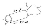
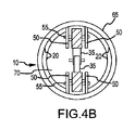
図4Aおよび図4Bはそれぞれ、インプラント10が送給用管状体(例えば、トロカール(套管針)、イントロデューサ・シース、針等)65から退出する様子を示す斜視図、ならびに管状体65およびインプラント10を示す横断面図であって、図4Aにおける4B−4B線に沿って取られたものであるが、図4Aおよび図4Bから理解されるように、複数枚のプレート20は、曲がり易い形状記憶材料または他の弾性材料で形成し、それにより、それらプレート20が、図2Aおよび図2Bに示す送給状態にあるときに、互いに巻き付くように巻き上がる(rolled up about each other)ようにすることが可能である。図4Aに示すように、それらプレート20が形状記憶材料または他の弾性材料で形成されているため、それらプレート20が送給用管状体65の遠位端から退出するにつれてそれらプレート20が送給用管状体65の内腔70の閉込めから解放され始めるとき、それらプレート20は、図1A、図2Aならびに図3Aおよび図3Bに示す、概して平面を成す状態に復元する(bias back)。
4A and 4B are perspective views showing the
図1Aおよび図2Aに示すように、エルボ部40を、矢印Aで示すように内側に移動させると、前記複数枚のプレート20は、矢印Bで示すように、互いに離れる向きに移動する。したがって、インプラント10がこのように展開されるとき、前記複数枚のプレート20は、後に詳述するように、椎骨骨折部を整復するために、骨に対抗するように作用することができる。
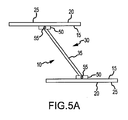
As shown in FIGS. 1A and 2A, when the
図5Aおよび図5Bはそれぞれ、インプラント10を展開状態および折畳み状態すなわち送給状態で示す側面図であるが、図5Aおよび図5Bに示すように、インプラント10は、ジャッキ30としての唯一のアーム(脚部)35を有し、その結果、エルボ部40が存在しない。ジャッキ30としてのアーム(脚部)35の各端部は、それぞれのプレート20のフランジ50に、ピボットピン55によって回動可能に取り付けられている。別のいくつかの実施形態においては、ジャッキ30が、はさみ型(X字型)構造を有する。ジャッキ30は、複数のアーム・セットが互いに平行に配置されたものを有することが可能である(各アーム・セットは、1本のアーム、2本のアームまたははさみ型(X字型)構造で構成することが可能である)。
5A and 5B are side views showing the
図6Aおよび図6Bはそれぞれ、インプラント10を部分展開状態および最大展開状態で示す側面図であるが、図6Aおよび図6Bに示すように、ジャッキ30は、ロック機構75を有し、そのロック機構75は、ジャッキ30すなわちインプラント10を最大展開状態で維持する。例えば、ロック機構75は、雄型ラッチ部材80と雌型ラッチ部材85とを有しており、雄型ラッチ部材80は、一対の脚部(アーム)35のうちの一方であって、雌型ラッチ部材85に係合するものに支持されており、雌型ラッチ部材85は、一対の脚部(アーム)35のうちの他方に支持されており、それにより、インプラント10を最大展開状態で固定する。
6A and 6B are side views showing the
図7は、インプラント10を部分展開状態で示す側面図であるが、図7に示すように、ジャッキ30は、ラチェット組立体90を有する。例えば、ラチェット面95が、一対の脚部(アーム)35のうちの一方に支持され、また、ポール歯(歯止め爪、pawl tooth)100が、一対の脚部(アーム)35のうちの他方に支持されている。エルボ部40の曲げ角がより鈍角になるようにジャッキ30の展開が進むにつれて、ポール歯100は、ラチェット面95に沿ってラチェット運動(一方向には運動するが、逆方向には運動しない一方向運動)を行うことになる。その結果、ラチェット組立体90は、全展開範囲のうちこれまでに到達された範囲のうちの最大の程度に維持されることになる。
FIG. 7 is a side view showing the
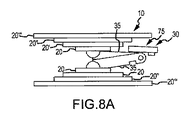
図8Aおよび図8Bはそれぞれ、インプラント10を折畳み状態すなわち送給状態および展開状態で示す側面図であるが、図8Aおよび図8Bに示すように、プレート20’、20’’、20’’’が、インプラント10のプレート20の上面に追加されて積層され、それにより、プレート20の剛性が増す。この実施形態については、後に、図10Aおよび図10Bを参照して詳述する。
8A and 8B are side views showing the
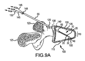
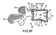
図2Aおよび図2Bに示すインプラント10を最小侵襲的に送給する方法を説明するために図9A−図9Fが参照されるが、図9A−図9Fは、椎体115の前部に骨折部110を有する椎骨105の、前後方向における(posterior-anterior)断面図であり、インプラント10を用いて骨折部110を整復する工程の進行を示す。図9A−図9Fから理解されるように、椎骨105は、椎体115およびその椎体115の前部に位置する骨折部110に加えて、椎弓根(pedicle)120、横突起123および棘突起125を有する。
Reference is made to FIGS. 9A-9F to describe a minimally invasive method of delivering the
図9Aに示すように、トロカール(套管針)またはカニューレ(排管)(送給用管状体)65が、椎弓根120内のうちの貫通位置(侵入位置、貫通開始位置)130まで延び、さらに、別の貫通位置(貫通終了位置)140を経て椎体115の内部空間135すなわち髄内空間内まで延びており、それにより、トロカール(カニューレ)(送給用管状体)65が、椎弓根120の貫通位置130から自身の遠位端(先端)までの部分が全体的に骨内に留まる。図9A−図9Fに示すこの実施形態においては、トロカール(カニューレ)(送給用管状体)65が、椎弓根120の上面近傍の貫通位置130において椎弓根120を貫通するとともに傾斜させられ、そして、横突起123の側面の横を通過するが、別のいくつかの実施形態においては、トロカール(カニューレ)(送給用管状体)65が、より水平な姿勢で椎弓根120まで延び、例えば横突起123の基部(base)近傍の位置を開始位置として、椎弓根120と同じ長さだけ延びて、椎体115の内部空間135に到達する。別のいくつかの実施形態においては、異なる手法および経路が椎体115の内部空間135に到達するために使用される。
As shown in FIG. 9A, a trocar (trocar) or cannula (delivery tube) 65 extends to a penetration position (invasion position, penetration start position) 130 within the
図9Aに示すように、押し出しデバイス(pushing device)148が用いれら、それにより、折畳み状態すなわち送給状態(図2B参照)にあるインプラント10が、トロカール(カニューレ)(送給用管状体)65内を遠位方向に通過して、インプラント10が椎体115の内部空間135内に送給されるまで押して前進させられる。一実施形態においては、押し出しデバイス148が、プッシュ・ロッド(押し棒)、シース(鞘)または他の管状部材であって、トロカール(カニューレ)(送給用管状体)65の内腔内を下流側に延びて、インプラント10のうちの近位端を押すためのものであり、それにより、インプラント10が、トロカール(カニューレ)(送給用管状体)65の内腔内を遠位方向に前進して椎体115の内部空間135に到達するようにする。別のいくつかの実施形態においては、図9Aに示すように、押し出しデバイス148が、複数のプッシュ部材(押す力を伝える部材)145およびプル部材(引く力を伝える部材)150を有するプッシュ・プル・デバイス(push-pull device)148として構成されている。図9Bおよび図9Cから最も良く理解されるように、一実施形態においては、複数のプッシュ部材145の遠位端が、インプラント10に、複数枚のプレート20と複数本の脚部(アーム)35との間にあるピボットピン55の近傍位置において連結されており、また、プル部材150の遠位端が、インプラント10に、複数本の脚部(アーム)35の間にあるエルボ部40のピボットピン45の近傍位置において連結されている。
As shown in FIG. 9A, a pushing
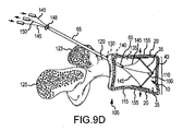
図9A−図9Dに示すように、インプラント10が椎体115の内部空間135内に送給されると、プル部材150が(それに関連付けられた矢印で示されるように)順次(徐々に)引き込まれるにつれて、複数のプッシュ部材145が(それに関連付けられた矢印で示されるように)順次(徐々に)押し出される。その結果、インプラント10の複数枚のプレート20が互いに離れる向きに順次(徐々に)変位させられ、それにより、椎体115の上端(サペリア・エンド)プレート155および下端(インフェリア・エンド)プレート155が、互いに離れる向きに移動させられる。具体的には、複数枚のプレート20が互いに離隔することにより、椎体115の内部空間135内に存在する網状骨が圧縮され、この圧縮は、このように離隔しているプレート20に発生する力が、椎体115の上端プレート155および下端プレート155を形成する皮質骨に伝達されるまで継続され、それにより、図9Dに示すように、上端プレート155および下端プレート155が互いに離れる向きに変位させられるとともに、椎体115の骨折部110が完全に整復される。
As shown in FIGS. 9A-9D, as the
図9Eに示すように、一実施形態においては、シリンジ(注射器)160またはそれに類似したデバイスが用いられ、それにより、椎体115の内部空間135内に、PMMA骨セメント165、PLA−PGA(ポリグリコール酸ポリ乳酸ポリマ)、ヒドロゲル(hydrogel)、骨形成蛋白質、幹細胞、死体骨(cadaver bone)、生体工学処理がなされた基質(matrix)等が注入される。PMMA骨セメント165または既述の他の材料が椎体115の内部空間135内に注入され、その注入は、可能な最大限度まで内部空間135がほぼ完全に充填されるとともに、図9Fに示すように、展開状態にあるインプラント10が内部空間135内に埋没するまで継続される。PMMA骨セメント165または既述の他の材料は、液体、ゲル、ペーストまたはスラリ(懸濁液)の状態で経皮的に送給することが可能である。
As shown in FIG. 9E, in one embodiment, a
図9Fに示すように、一実施形態においては、プッシュ部材145およびプル部材150が、椎弓根120のうちの貫通位置(開口部)130において切り離されるとともに、クリンプ(crimp、圧着具)、ボタン(留め)または他の部材170が、切り離されたプッシュ部材145およびプル部材150に連結され、それにより、それらプッシュ部材145およびプル部材150が適切な位置に保持され、それにより、インプラント10が、図9D−図9Fに示すように、最大展開状態で維持される。
As shown in FIG. 9F, in one embodiment, the
別のいくつかの実施形態においては、プッシュ部材145およびプル部材150が、インプラント10上の適当な位置に、(例えば、フック、タブ(つまみ)等を介して)一時的に連結され、その後、インプラント10から完全に分離されて患者から取り外される。この種の実施形態においては、図6Aおよび図6Bに示すロック機構(locking mechanism)75または図7に示すラチェット機構(ratcheting mechanism)(ラチェット組立体)90が採用され、それにより、展開状態にあるインプラント10からプッシュ部材145およびプル部材150が取り外されると、インプラント10が最大展開状態で保持されることが可能である。
In some other embodiments, the
要するに、図1A−図9Fに示すいくつかの実施形態においては、2つの金属製の要素(elements)が存在し、それら要素は、ヒンジ機構によって互いに取り付けられていて、折り畳まれてトロカール(カニューレ)(送給用管状体)65内に挿入されることになる複数枚のプレート20を形成する。インプラント10を椎体115内に押し込むイントロデューサ(introducer)を用いれば、インプラント10が、カニューレ(トロカール)(送給用管状体)65を超えた位置まで前進させられ、そして、椎体115内において、開いた曲線的形状(open curved shape)から、その形状より平面的な形状に変形する。トロカール(カニューレ)(送給用管状体)65をカテーテル(骨)内で使用すると、前記ヒンジ機構の角度が、より鋭角的な角度からより鈍角的な角度に変化し、それにより、前記2枚のプレート20間の間隔が増加する。これにより、「修復操作(reduction maneuver)」が行われることによって骨の位置が機械的に改善される。前記ヒンジ機構内にロック機構を設けた場合には、前記ヒンジ機構が目標位置に到達すると、前記ヒンジ機構が適切な位置に固定される。このような作動は、ラチェット機構、ロック機構またはクリンピング(crimping、圧着)機構を用いることによって実施可能である。
In summary, in some embodiments shown in FIGS. 1A-9F, there are two metal elements that are attached to each other by a hinge mechanism and folded into a trocar (cannula). (Tube for feeding) A plurality of
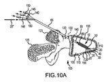
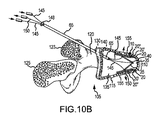
図10Aおよび図10Bは、図8Aおよび図8Bに示す実施形態が展開状態にあることを示す点を除き、図9Aおよび図9Bと同様の図であるが、図10Aおよび図10Bから理解されるように、送給シース180が、トロカール(カニューレ)(送給用管状体)65内の経路に沿って移動させられ、それにより、図8Aおよび図8Bを参照して説明した前述の補助プレート20’、20’’を送給可能となっている。具体的には、図9Aを参照して既述したように、インプラント10がトロカール(カニューレ)(送給用管状体)65を経由して送給される。その後、送給シース180は、自身の遠位端がトロカール(カニューレ)(送給用管状体)65の遠位端から突出するまで、トロカール(カニューレ)(送給用管状体)65内の経路に沿って前進させられる。補助プレート20’、20’’は、巻き上げられて円筒状を成しているが、送給シース180の内腔内の経路を前進して椎体115の内部空間135内に到達し、このことは、送給シース180内において、シース状を成す各補助プレート20’、20’’の背後において挿入されたある部材を下流側に押すことによって行われる。それらシース状の補助プレート20’、20’’は、ひとたび内部空間135内に入ると、図8Aおよび図8Bに示す、概して平面的な状態に復元することが可能である。それら補助プレート20’、20’’は、送給シース180により、すなわち、この送給シース180内を通過して延びるプッシュ部材により、図10Aおよび図10Bに示す位置に配置される。インプラント10は、その後、図9B−図9Fを参照して説明したように、展開されて骨内に移植される。
FIGS. 10A and 10B are similar to FIGS. 9A and 9B except that the embodiment shown in FIGS. 8A and 8B is in a deployed state, but are understood from FIGS. 10A and 10B. As such, the
要するに、図8Aおよび図8Bならびに図10Aおよび図10Bを参照して説明したように、一連の複数枚のプレートを積層状態で配置することが可能であり、その積層配置は、大きなプレートは外面上に位置し、順に小さくなる複数枚のプレートは、前記ヒンジ機構に最も近い内面上に位置するように行われ、それにより、組み合わされた複数枚のプレートについての強度または剛性が向上する。 In short, as described with reference to FIG. 8A and FIG. 8B and FIG. 10A and FIG. 10B, it is possible to arrange a series of a plurality of plates in a stacked state. The plurality of plates, which are located in the order of decreasing size, are arranged so as to be located on the inner surface closest to the hinge mechanism, thereby improving the strength or rigidity of the combined plurality of plates.
別の実施形態を説明するために図11が参照されるが、図11は、蓄積型のインプラント210を形成する複数のインクリメンタル・インプラント要素(incremental implant elements)205を増分的に(少量の増分ずつ順次)送給する送給デバイス200を示す側面図(部分断面図)である。図11に示すように、この送給デバイス200は、ハンドル215と、トリガ220と、ばね225と、プランジャ・ロッド(plunger rod)230と、ホッパ(じょうご状容器)235と、トロカール240と、通路245であってホッパ235とトロカール240の遠位端との間を延びるものとを有する。トリガ220は、ハンドル215に回動可能に取り付けられ、プランジャ・ロッド230の近位端面に対抗するように作用する。プランジャ・ロッド230は、ばね225によって近位方向に付勢されるとともに、通路245内にまで延びている。トロカール240は、ホッパ235およびハンドル215から遠位方向に延びている。トリガ220を引くと、プランジャ・ロッド230がばね225に逆らって作用し、通路245を下流側に延びる。トリガ220を離すと、ばね225がプランジャ・ロッド230を近位方向に付勢することが可能となる。インクリメンタル・インプラント要素205は、ホッパ235に充填され、通路245に移行する。バイアスされた(偏倚した)出口リップ(end lips)250は、トリガ220の操作によるプランジャ・ロッド230の遠位方向への変位によって少なくとも一つのインクリメンタル・インプラント要素205が出口リップ250を通過して放出されるまでの期間、複数のインクリメンタル・インプラント要素205を、トロカール240の通路245内に保持する。プランジャ・ロッド230のストロークの長さに応じて、トリガ220の各回の操作毎に、1つ、2つ、3つまたはそれより多数のインクリメンタル・インプラント要素205が放出され得る。
Reference is made to FIG. 11 to describe another embodiment, which shows incremental
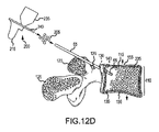
複数のインクリメンタル・インプラント要素205を最小侵襲的に送給して、蓄積型インプラント(複数の要素の蓄積によって全体が形成される蓄積型のインプラント)210を生成する方法を説明するために図12A−図12Eが参照されるが、図12A−図12Eは、椎体115の前部に骨折部110を有する椎骨105の、前後方向における断面図であり、図12A−図12Eは、蓄積型または内部組立型インプラント210を用いて骨折部110を整復する工程の進行を示す。図12A−図12Eから理解されるように、椎骨105は、椎体115およびこの椎体115の前部に位置する骨折部110に加えて、椎弓根120、横突起123および棘突起125を有する。
To illustrate how a plurality of
図12Aに示すように、トロカールまたはカニューレ(送給用管状体)65が、椎弓根120内のうちの貫通位置(侵入位置、貫通開始位置)130まで延び、さらに、別の貫通位置(貫通終了位置)140を経て椎体115の内部空間135すなわち髄内空間内まで延びており、それにより、トロカール(カニューレ)(送給用管状体)65は、椎弓根120の貫通位置130から自身の遠位端(先端)までの部分が全体的に骨内に留まる。図12A−図12Fに示すこの実施形態においては、トロカール(カニューレ)(送給用管状体)65が、椎弓根120の上面近傍の貫通位置130において椎弓根120を貫通するとともに傾斜させられ、そして、横突起123の側面の横を通過するが、別のいくつかの実施形態においては、トロカールまたはカニューレ(送給用管状体)65が、より水平な姿勢で椎弓根120まで延び、例えば横突起123の基部(base)近傍の位置を開始位置として、椎弓根120と同じ長さだけ延びて、椎体115の内部空間135に到達する。別のいくつかの実施形態においては、異なる手法および経路が椎体115の内部空間135に到達するために使用される。
As shown in FIG. 12A, a trocar or cannula (feeding tubular body) 65 extends to a penetration position (invasion position, penetration start position) 130 in the
図12Aに示すように、図11に示す送給デバイス200が用いられ、それにより、複数のインクリメンタル・インプラント要素205が、椎体115の内部空間135内に増分的に(少しずつ順次)送給される。一実施形態においては、送給デバイス200のトロカール240が、トロカール(カニューレ)(送給用管状体)65の内腔に挿入されて椎体115の内部空間135内に至り、それにより、複数のインクリメンタル・インプラント要素205を送給する。別のいくつかの実施形態においては、外側にあるトロカール(カニューレ)(送給用管状体)65が使用されず、そのトロカール(カニューレ)(送給用管状体)65に代わって、送給デバイス200のトロカール240のみが挿入される。
As shown in FIG. 12A, the
図12A−図12Dに示すとともに図11を参照して上述したように、送給デバイス200のトリガ220を繰り返し握ることにより、送給デバイス200が、複数のインクリメンタル・インプラント要素205を、椎体115の内部空間135内に増分的に(少しずつ順次)送給するために用いられる。具体的には、往復運動するプランジャ・ロッド230によって、複数のインクリメンタル・インプラント要素205が、椎体115の内部空間135内に押し込まれる。インクリメンタル・インプラント要素205の、椎体115の内部空間135内における蓄積量または内部組立量が次第に増加するにつれて、蓄積された複数のインクリメンタル・インプラント要素205により、椎体115の内部空間135内に存在する網状骨が圧縮され、この圧縮は、蓄積された複数のインクリメンタル・インプラント要素205に発生する力が、椎体115の上端プレート155および下端プレート155を形成する皮質骨に伝達されるまで継続され、それにより、図12Dに示すように、上端プレート155および下端プレート155が互いに離れる向きに変位させられるとともに、椎体115の骨折部10が完全に整復される。
As shown in FIGS. 12A-12D and described above with reference to FIG. 11, by repeatedly grasping the
一実施形態においては、インクリメンタル・インプラント要素205は、球状であり、約0.5mm(ミリメートル)から約1.0cmまでの範囲内の、概して均一な半径を有する。別のいくつかの実施形態においては、インクリメンタル・インプラント要素205が、例えば、円盤状、円柱状もしくは円筒状、立方体状、ピラミッド状、星形、卵形等のような他の形状を有する。それぞれの実施形態に依存するが、インクリメンタル・インプラント要素205の候補となる材料としては、生体適合性を有する金属(例えば、ステンレス鋼、チタン等)、生体適合性を有するポリマ(例えば、ナイロン、PEBAX(登録商標)等)、生体適合性を有するセラミック、生体適合性を有する複合材料(composites)、PMMA骨セメント、PLA−PGA、ヒドロゲル、骨形成蛋白質、幹細胞、死体骨、生体工学処理がなされた基質等が挙げられる。
In one embodiment, the
いくつかの実施形態においては、複数のインクリメンタル・インプラント要素205が、すべて同一の材料から形成される。具体的には、例えば、すべてのインクリメンタル・インプラント要素205が、生体適合性を有する金属であってもよく、または、PMMA骨セメント、PLA−PGA、ヒドロゲル、骨形成蛋白質、幹細胞、死体骨、もしくは生体工学処理がなされた基質等であってもよい。
In some embodiments, the plurality of
別のいくつかの実施形態においては、複数のインクリメンタル・インプラント要素205が、複数の材料から形成されている(例えば、いくつかの要素205は第1材料から形成され、また、他の要素205は第2材料または第3材料から形成される)。具体的には、例えば、複数のインクリメンタル・インプラント要素205のうち、4分の1から半分までの範囲内の数のものが、生体適合性を有する金属であり、残りの4分の3から半分までの範囲内の数のものが、PMMA骨セメント、PLA−PGA、ヒドロゲル、骨形成蛋白質、幹細胞、死体骨、または生体工学処理がなされた基質等である。このような様々な種類のインクリメンタル・インプラント要素205は、椎体115の内部空間135内において予定通りに混合されることが確保されるように、送給デバイス200内において一定の順序で配列してもよい。例えば、ディスペンサ(dispenser)である送給デバイス200において、金属で形成された複数のインクリメンタル・インプラント要素205と、生体活性を有する複数のインクリメンタル・インプラント要素205とが交互に並んでいてもよく、または、最初の10個のインクリメンタル・インプラント要素205が金属で形成され、それに続く数個のインクリメンタル・インプラント要素205が生体活性を有する要素であるかもしくは生体活性/金属性を有する要素(すなわち、後述の複合材料からなる要素205)であってもよい。
In some other embodiments, a plurality of
いくつかの実施形態においては、複数のインクリメンタル・インプラント要素205が、複数の材料で形成された複合構造を有する(例えば、個々の要素205が2つ以上の材料で形成される)。具体的には、例えば、複数のインクリメンタル・インプラント要素205は、生体適合性を有する金属で形成された多孔質の外殻を有しており、その外殻の内側が、PMMA骨セメント、PLA−PGA、ヒドロゲル、骨形成蛋白質、幹細胞、死体骨、または生体工学処理がなされた基質等で充填されてもよい。これに代えて、例えば、複数のインクリメンタル・インプラント要素205は、生体適合性を有する金属で形成された、内側のコア部と、PMMA骨セメント、PLA−PGA、ヒドロゲル、骨形成蛋白質、幹細胞、死体骨、または生体工学処理がなされた基質等で形成された、外側のシェル部とを有してもよい。
In some embodiments, the plurality of
図12Eに示す一実施形態においては、蓄積型のインプラント210が骨折部110を完全に整復すると、トロカール(カニューレ)(送給用管状体)65および送給デバイス200が取り外され、貫通位置130および140が閉塞される。複数のインクリメンタル・インプラント要素205のうちのいくつか、またはそれらインクリメンタル・インプラント要素205のうちのいくつかのアスペクト(側面、aspect)が、PMMA骨セメント、PLA−PGA、ヒドロゲル、骨形成蛋白質、幹細胞、死体骨、または生体工学処理がなされた基質等を含有する場合には、このような材料は、蓄積型のインプラント210内における骨の成長の誘発を促進する役割を果たす。
In one embodiment, shown in FIG. 12E, once the
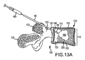
図13Aおよび図13Bは、完全に整復された椎体115を図12Eと同様に示す図であるが、図13Aおよび図13Bに示すように、一実施形態においては、シリンジ160またはそれに類似したデバイスが用いられ、それにより、椎体115の内部空間135内に、PMMA骨セメント165、PLA−PGA、ヒドロゲル、骨形成蛋白質、幹細胞、死体骨、または生体工学処理がなされた基質等が注入される。PMMA骨セメント165または既述の他の材料が椎体115の内部空間135内に注入され、その注入は、可能な最大限度まで内部空間135がほぼ完全に充填されるとともに、図13Bに示すように、蓄積型のインプラント210が内部空間135内に埋没するまで継続される。
13A and 13B show a fully reduced
図13Aおよび図13Bから理解されるように、いくつかの実施形態においては、複数のインクリメンタル・インプラント要素205が、ディスペンサである送給デバイス200から分散して放出され、それらインクリメンタル・インプラント要素205が、上述した液状またはペースト状の材料165としてのグラウト(grout)と混合させられる。この場合、複数のインクリメンタル・インプラント要素205と液状またはペースト状の材料165との配置であって図13Bに示すものを達成するために一つの工程が設けられることになる。
As can be seen from FIGS. 13A and 13B, in some embodiments, a plurality of
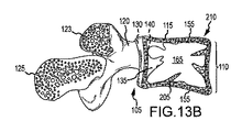
別の蓄積型インプラント310を生成するための螺旋ばね型インプラント要素305についてのさらに別の実施形態を説明するために図14Aおよび図14Bが参照されるが、図14Aおよび図14Bはそれぞれ、螺旋ばね型インプラント要素305を拘束状態および自由状態で示す側面図である。図14Aに示すように、螺旋ばね型インプラント要素(インクリメンタル・インプラント要素)305が拘束状態にある場合(例えば、トロカールまたはカニューレ(送給用管状体)65の内腔内に閉じ込められている場合)、螺旋ばね型インプラント要素305は、減少した直径Aと、増加した長さXとを有する螺旋ばねである。図14Bに示すように、螺旋ばね型インプラント要素305が、自由な非拘束状態にある場合(例えば、トロカールまたはカニューレ(送給用管状体)65の内腔から解放されている場合)、螺旋ばね型インプラント要素305は、増加した直径Bと、減少した長さYとを有し、ここに、XはYより大きく、AはBより小さい。
Reference is made to FIGS. 14A and 14B to describe yet another embodiment of a helical
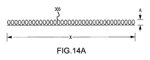
図15Aおよび図15Bは、図14Aおよび図14Bに示す螺旋ばね型インプラント要素305が展開されている点を除き、図12Aおよび図12Bと同様の図であるが、図15Aおよび図15Bから理解されるように、トロカールまたはカニューレ(送給用管状体)65が、椎弓根120内のうちの貫通位置(侵入位置、貫通開始位置)130まで延び、さらに、他の貫通位置(貫通終了位置)140を経て椎体115の内部空間135すなわち髄内空間内まで延びており、それにより、トロカール(カニューレ)(送給用管状体)65は、椎弓根120の貫通位置130から自身の遠位端(先端)までの部分が全体的に骨内に留まる。図15A−図15Fに示すこの実施形態においては、トロカール(カニューレ)(送給用管状体)65が、椎弓根120の上面近傍の貫通位置130において椎弓根120を貫通するとともに傾斜させられ、そして、横突起123の側面の横を通過するが、別のいくつかの実施形態においては、トロカールまたはカニューレ(送給用管状体)65が、より水平な姿勢で椎弓根120まで延び、例えば横突起123の基部(base)近傍の位置を開始位置として、椎弓根120と同じ長さだけ延びて、椎体115の内部空間135に到達する。別のいくつかの実施形態においては、異なる手法および経路が椎体115の内部空間135に到達するために使用される。
15A and 15B are similar to FIGS. 12A and 12B except that the helical
図15Aに示すように、プッシュ・ロッド315を用いることにより、複数の螺旋ばね型インプラント要素305が、椎体115の内部空間135内に増分的に(少しずつ順次)送給される。その際、螺旋ばね型インプラント要素305は、図14Aに示すように、拘束状態(直径減少状態)で、トロカール(カニューレ)(送給用管状体)65にそれの近位端から装填される。プッシュ・ロッド315は、螺旋ばね型インプラント要素305を椎体115の内部空間135内にまで押し込む。図15Aに示すように、螺旋ばね型インプラント要素305は、トロカール(カニューレ)(送給用管状体)65の遠位端から退出して椎体115の内部空間135内に至ると、図14Bに示すように、解放されて非拘束状態(直径増加状態)となる。いくつかの実施形態においては、螺旋ばね型インプラント要素305が図14Bに示す非拘束状態にスムーズに移行することを促進するために、プッシュ・ロッド315が最初に、トロカール(カニューレ)(送給用管状体)65を通って椎体115の内部空間135内に挿入され、それにより、網状骨が圧縮されるとともに、螺旋ばね型インプラント要素305の直径が増加する空間が提供される。
As shown in FIG. 15A, by using a
図15Bに示すように、複数の螺旋ばね型インプラント要素305が椎体115の内部空間135内に繰り返し送給される結果、蓄積型インプラント310が生成される。図12C−12Eを参照して説明したのと同様の方法で、螺旋ばね型インプラント要素305の送給と螺旋ばね型インプラント要素305の直径増加状態への移行とが繰り返される結果、最終的に、骨折部110が完全に整復される。具体的には、蓄積型インプラント310が網状骨に対抗するように作用し、蓄積型インプラント310の力が椎体115の上端プレート155および下端プレート155を形成する皮質骨に伝達され、それにより、骨折部110が整復される。この時点で、外科的処置を完了してもよいし、または、これに代えて、PMMA骨セメント、PLA−PGA、ヒドロゲル、骨形成蛋白質、幹細胞、死体骨、または生体工学処理がなされた基質等を、図13Aおよび図13Bを参照して説明したのと同様の方法で、椎体115の内部空間135内に注入してもよい。
As shown in FIG. 15B, a plurality of helical
一実施形態においては、螺旋ばね型インプラント要素305が、拘束状態で、約0.5mmから約5mmまでの範囲内の直径Aと、約0.5cmから約4cmまでの範囲内の長さXとを有している。また、螺旋ばね型インプラント要素305は、非拘束状態で、約0.5cmから約4cmまでの範囲内の直径Bと、約1cmから約4cmまでの範囲内の長さYとを有している。一実施形態においては、螺旋ばね型インプラント要素305がステンレス鋼から形成されている。
In one embodiment, the helical
図14Aおよび図14Bに示す螺旋ばね型インプラント要素305についての一実施形態においては、螺旋ばね型インプラント要素305が、図14Aに示す直径減少状態で送給される。椎体115の内部空間135に送給されると、螺旋ばね型インプラント要素305の一端部が、例えばねじ、接着剤、ピン等によって骨に固定されるか、または、螺旋ばね型インプラント要素305の前記一端部の位置において椎体115の内部空間135内において回転しない部材に取り付けられることにより、固定される。螺旋ばね型インプラント要素305の他端部が、その後、螺旋ばね型インプラント要素305の巻きを緩めるために回転させられ、この回転は、螺旋ばね型インプラント要素305の直径が直径Aから目標値である直径Bに変化し、螺旋ばね型インプラント要素305の長さも長さXから長さYに変化するまで、継続される。このような直径増大により、椎体115の複数枚のプレート155が互いに離れる向きに変位させられ、それにより、骨折部110が整復される。螺旋ばね型インプラント要素305の一端部であって螺旋ばね型インプラント要素305の巻きを緩めるために作用するものは、その後、先に固定されている他端部と同様の方法で固定することが可能である。
In one embodiment for the spiral
別の蓄積型インプラント410を生成する円筒型インプラント要素405についてのさらに別の実施形態を説明するために図16Aおよび図16Bが参照されるが、図16Aおよび図16Bはそれぞれ、複数の円筒型インプラント要素405を示す側面図および端面図である。図16Aおよび図16Bに示すように、インクリメンタル・インプラント要素である円筒型インプラント要素405は、円柱状または円筒状であり、約0.1cmから約2cmまでの範囲内の概して均一な直径と、約0.5cmから約4cmまでの範囲内の長さとを有する。それぞれの実施形態に依存するが、円筒型インプラント要素405のための候補となる材料としては、生体適合性を有する金属(例えば、ステンレス鋼、チタン等)、生体適合性を有するポリマ(例えば、ナイロン、PEBAX(登録商標)等)、生体適合性を有するセラミック、生体適合性を有する複合材料、PMMA骨セメント、PLA−PGA、ヒドロゲル、骨形成蛋白質、幹細胞、死体骨、または生体工学処理がなされた基質等が挙げられる。
Reference is made to FIGS. 16A and 16B to illustrate yet another embodiment for a
いくつかの実施形態においては、複数の円筒型インプラント要素405が、すべて同一の材料から形成される。具体的には、例えば、すべての円筒型インプラント要素405は、生体適合性を有する金属であってもよく、または、PMMA骨セメント、PLA−PGA、ヒドロゲル、骨形成蛋白質、幹細胞、死体骨、もしくは生体工学処理がなされた基質等であってもよい。
In some embodiments, the plurality of
別のいくつかの実施形態においては、複数の円筒型インプラント要素405が、複数の材料から形成されている(例えば、いくつかの要素405は第1材料から形成され、また、他の要素405は第2材料または第3材料から形成される)。具体的には、例えば、複数の円筒型インプラント要素405のうち、4分の1から半分までの範囲内の数のものが、生体適合性を有する金属であり、残りの4分の3から半分までの範囲内の数のものが、PMMA骨セメント、PLA−PGA、ヒドロゲル、骨形成蛋白質、幹細胞、死体骨、または生体工学処理がなされた基質等である。図11に示すディスペンサである送給デバイス200が、ホッパ235の代わりにマガジン(magazine)を備えてもよく、そのマガジンは、複数の円筒型インプラント要素405を、トロカール240を通して送給するのに望ましい向きで供給するように構成される。このような様々な種類の円筒型インプラント要素405は、椎体115の内部空間135内において予定通りに混合されることが確保されるように、送給デバイス200内において一定の順序で配列してもよい。例えば、ディスペンサ(dispenser)である送給デバイス200において、金属で形成された複数の円筒型インプラント要素405と、生体活性を有する複数の円筒型インプラント要素405とが交互に並んでいてもよく、または、最初の10個の円筒型インプラント要素405が金属で形成され、それに続く数個の円筒型インプラント要素405が生体活性を有する要素であるかもしくは生体活性/金属性を有する要素(すなわち、後述の複合材料からなる要素405)であってもよい。
In some other embodiments, a plurality of
いくつかの実施形態においては、複数の円筒型インプラント要素405が、複数の材料で形成された複合構造を有する(例えば、個々の要素405が2つ以上の材料で形成される)。具体的には、例えば、複数の円筒型インプラント要素405は、生体適合性を有する金属で形成された多孔質の外殻を有しており、その外殻の内側が、PMMA骨セメント、PLA−PGA、ヒドロゲル、骨形成蛋白質、幹細胞、死体骨、または生体工学処理がなされた基質等で充填されてもよい。これに代えて、例えば、複数の円筒型インプラント要素405は、生体適合性を有する金属で形成された、内側のコア部と、PMMA骨セメント、PLA−PGA、ヒドロゲル、骨形成蛋白質、幹細胞、死体骨、または生体工学処理がなされた基質等で形成された、外側のシェル部とを有していてもよい。
In some embodiments, the plurality of
いくつかの実施形態においては、図16Aおよび図16Bに示すシ円筒型インプラント要素405が、空洞(void)が概して存在しない中実円柱形状を成す。別の実施形態においては、円筒型インプラント要素405が、筒状(例えば、全体的に中空な形状)である。
In some embodiments, the
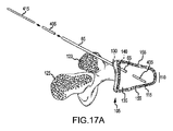
図17Aおよび図17Bは、図16Aおよび図16Bに示す円筒型インプラント要素405が展開されている点を除き、図12Aおよび図12Bと同様の図であるが、図17Aおよび図17Bに示すように、トロカールまたはカニューレ(送給用管状体)65が、椎弓根120内のうちの貫通位置(侵入位置、貫通開始位置)130まで延び、さらに、他の貫通位置(貫通終了位置)140を経て椎体115の内部空間135すなわち髄内空間内まで延びており、それにより、トロカール(カニューレ)(送給用管状体)65は、椎弓根120の貫通位置130から自身の遠位端(先端)までの部分が全体的に骨内に留まる。図17Aおよび図17Bに示すこの実施形態においては、トロカール(カニューレ)(送給用管状体)65が、椎弓根120の上面近傍の貫通位置130において椎弓根120を貫通するとともに傾斜させられ、そして、横突起123の側面の横を通過するが、別のいくつかの実施形態においては、トロカールまたはカニューレ(送給用管状体)65が、より水平な姿勢で椎弓根120まで延び、例えば横突起123の基部(base)近傍の位置を開始位置として、椎弓根120と同じ長さだけ延びて、椎体115の内部空間135に到達する。別のいくつかの実施形態においては、異なる手法および経路が椎体115の内部空間135に到達するために使用される。
FIGS. 17A and 17B are similar to FIGS. 12A and 12B except that the
図17Aに示すように、プッシュ・ロッド415、または図11に示す送給デバイス200が変更されたものを用いることによって、複数の円筒型インプラント要素405を増分的に(少しずつ順次)椎体115の内部空間135内に送給してもよい。その際、円筒型インプラント要素405は、トロカール(カニューレ)(送給用管状体)65にそれの近位端から装填され、プッシュ・ロッド415が、円筒型インプラント要素405を椎体115の内部空間135内に押し込む。
As shown in FIG. 17A, by using a
図17Bに示すように、複数の円筒型インプラント要素405が椎体115の内部空間135内に繰り返し送給される結果、蓄積型インプラント410が生成される。図12C−12Eを参照して説明したのと同様の方法で、椎体115の内部空間135内への円筒型インプラント要素405の送給が繰り返される結果、最終的に、骨折部110が完全に整復される。具体的には、蓄積型インプラント410が網状骨に対抗するように作用し、蓄積型インプラント410の力が椎体115の上端プレート155および下端プレート155を形成する皮質骨に伝達され、それにより、骨折部110が整復される。この時点で、外科的処置を完了してもよいし、または、これに代えて、PMMA骨セメント、PLA−PGA、ヒドロゲル、骨形成蛋白質、幹細胞、死体骨、または生体工学処理がなされた基質等を、図13Aおよび図13Bを参照して説明したのと同様の方法で、椎体115の内部空間135内に注入してもよい。
As shown in FIG. 17B, a plurality of
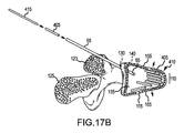
一実施形態においては、図16Aおよび図16Bに示す円筒型インプラント要素405が、図1Aおよび図1Bに示す複数枚のプレート20に類似した複数枚のプレートであり、それらプレートは、(図4Aおよび図4Bに示すように)巻き上げられて円筒状を成す状態で送給されるが、トロカール(カニューレ)(送給用管状体)65から退出すると平面的な状態に移行する。図18は、図1A、図1B、図4Aおよび図4Bを参照して説明したのと同様な平面状のプレートに変形した円筒型インプラント要素405を採用する蓄積型のインプラント510を示す側面図であるが、図18から理解されるように、追加される複数の追加インプラント要素505が、椎体115の内部空間135内に送給される。それら追加インプラント要素505は、配向に関する特徴部または係合に関する特徴部を有する形状を有している。例えば、追加インプラント要素505は、レゴ(LEGOS、登録商標)の如くかみ合うかまたは相互に固定される形状または構造を有しており、それにより、円筒型インプラント要素405と追加インプラント要素505とが椎体115の内部空間135内において組み立てられることが可能となり、それにより、蓄積型または内部組立型のインプラント510が構築される。
In one embodiment, the
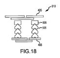
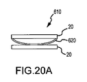
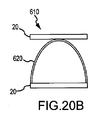
いくつかの実施形態においては、図2Aおよび図2Bに示すインプラント20が、概して自動的に展開を行う機構を有している。例えば、図19Aおよび図19Bはそれぞれ、インプラント610を送給可能状態および展開状態で示す側面図であるが、図19Aおよび図19Bに示すように、インプラント610は、図2Aおよび図2Bに示すインプラント10と同様の複数枚のプレート20を有しているが、インプラント610は、図2Aおよび図2Bに示すインプラント20に採用されたジャッキ30の代わりに、少なくとも一つの螺旋ばね615を採用している。別のいくつかの実施形態においては、図19Aおよび図19Bと同様の図である図20Aおよび図20Bに示すように、インプラント610が、螺旋ばね615の代わりに、板ばね620を採用している。
In some embodiments, the
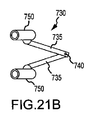
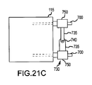
図21Aは、骨折した椎体115を示す正面図であるが、図21Aから理解されるように、複数本のロッド700が、骨折した椎体115内に挿入されている。それらロッド700は、図21Bの斜視図に示すように、ジャッキ730への連結が可能な状態で、椎体115から突出している。図21Bに示すように、ジャッキ730は、複数本のアーム735と、ヒンジで連結されたエルボ部740と、ロッド700のうち露出した端部に連結される2つのカプラ750とを有している。各アーム735の一端部同士は、互いに回動可能に連結されてエルボ部740を形成している。各アーム735の他端部は、それぞれのカプラ750に回動可能に連結されている。図21Cは、ジャッキ730がロッド700に取り付けられている点を除き、図21Aと同様の図であるが、図21Cに示すように、ジャッキ730は、複数本のロッド700を駆動して互いに離隔させ、骨折部110を整復するために、展開させられ得る。ジャッキ730は、ひとたび予定通りに展開されると、クリンピング(圧着)機構、ロック機構、ラチェット機構等により、適切な位置に固定され得る。
FIG. 21A is a front view showing the fractured
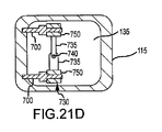
図21Aおよび図21Cに示すこの実施形態においては、複数本のロッド700が骨から突出しているとともに、ジャッキ730がその骨の外部に位置しているが、別のいくつかの実施形態においては、断面図である点を除き図21Cと同様である図21Dに示すような形態であってもよい。具体的には、複数本のロッド700は、皮質骨から椎体115の内部空間135内に延び、また、ジャッキ730は、内部空間135内に位置してそれらロッド700に連結され、それにより、それらロッド700同士を互いに離隔させて骨折部110を整復する。
In this embodiment shown in FIGS. 21A and 21C,
一実施形態においては、図1A−図10Bを参照して説明した一連のインプラント10が、骨折した椎体115の内部空間135がそれらインプラント10の設置によって充填されて骨折部110が整復されるまでの期間、順次または同時に挿入される。
In one embodiment, the series of
以上説明した複数の実施形態のうち、前記インプラントが、送給デバイスによって送給される複数のインクリメンタル・インプラント要素によって形成される蓄積型インプラントであるいくつかの実施形態(例えば、図11、図12A−図12Eならびに図17Aおよび図17B参照)のいずれについても、前記送給デバイスおよび前記複数のインクリメンタル・インプラント要素が、椎骨骨折部を治療するシステムを形成するようにしてもよく、また、それら送給デバイスおよび複数のインクリメンタル・インプラント要素が、無菌包装された送給デバイスおよび複数のインクリメンタル・インプラント要素を含む医療キットという形態で提供されるようにしてもよい。それらキットおよびシステムの取扱説明書は、包装によるかまたはインターネットを介して入手可能であるようにしてもよい。 Of the embodiments described above, some embodiments wherein the implant is a storage implant formed by a plurality of incremental implant elements delivered by a delivery device (eg, FIGS. 11, 12A). -For any of FIGS. 12E and 17A and 17B), the delivery device and the plurality of incremental implant elements may form a system for treating vertebral fractures, and the delivery The delivery device and the plurality of incremental implant elements may be provided in the form of a medical kit including a sterile packaged delivery device and the plurality of incremental implant elements. The kit and system instructions may be made available by packaging or via the Internet.
以上説明した複数の実施形態のいずれについても、前述のカニューレ、カテーテル、シースまたはトロカール(送給用管状体)65が、蛍光可視化法(fluoroscopic visualization)の下で患者の体内に設置される。一実施形態においては、トロカール(送給用管状体)65が、骨折した椎体115の後外側にある椎弓根120を通過するが、トロカール(送給用管状体)65の先端は、椎体115の後面より内側に位置している。以上説明したインプラントまたはそれの構成要素のいずれにも、自身が蛍光透視によって追跡されることを容易にする特徴部を追加してもよい。例えば、インプラントまたはそれの構成要素は、それの一端部において、特徴的形状であって、蛍光透視により観察可能であるとともに、当該インプラントまたはそれの構成要素の向きを示すものを有してもよい。また、インプラントまたはそれの構成要素は、それの一端部において、放射線不透過性(例えば、タングステン、白金等)のマーカであって、蛍光透視によって観察可能であるとともに、当該インプラントまたはそれの構成要素の向きを示すものを備えてもよい。
In any of the embodiments described above, the aforementioned cannula, catheter, sheath or trocar (delivery tubular body) 65 is placed in the patient's body under fluoroscopic visualization. In one embodiment, a trocar (feeding tubular body) 65 passes through the
以上説明した複数のインプラントのうちのいずれかを用いて整復を実施した後、いくつかの実施形態においては、カテーテルの設置を容易にするためにトロカールが挿入され、そのカテーテルにより、骨充填材、骨ボイド(bone void)、ポリメチルメタクリレート骨セメント、骨形成蛋白質材料、骨移植用材料またはそれら材料の組合せを骨折した椎体内に挿入することが可能となり、それら材料の挿入により、骨折部をさらに安定化させてそれの形状を保持し、それにより、椎体の高さが圧迫により減少してしまうことが防止される。 After performing reduction using any of the multiple implants described above, in some embodiments, a trocar is inserted to facilitate catheter placement, and the catheter allows the bone filler, Bone void, polymethylmethacrylate bone cement, bone morphogenetic protein material, bone grafting material or a combination of these materials can be inserted into the fractured vertebral body, and the insertion of these materials will cause the fracture It is further stabilized to retain its shape, thereby preventing the height of the vertebral body from being reduced by compression.
以上、望ましいいくつかの実施形態を参照しながら本発明を説明したが、当業者であれば、本発明の主旨からも範囲からも逸脱することなく、形式(form)および詳細(detail)に関する変更を行うことが可能であることを認識するであろう。 Although the present invention has been described with reference to some preferred embodiments, those skilled in the art will recognize changes in form and detail without departing from the spirit and scope of the invention. Will recognize that it is possible to do.
本発明によって下記の各態様が得られる。
(1) 椎体における骨折部を整復する椎体骨折部整復方法であって、
インプラントを前記椎体の内部空間内に経皮的に挿入する挿入工程と、
前記インプラントのうちの第1部材および第2部材を前記内部空間内において互いに離れる向きに変位させ、それにより、前記椎体における前記骨折部を骨折整復状態に移行させる変位工程と、
前記椎体における前記骨折部が前記骨折整復状態に維持されるように、前記第1部材および前記第2部材を相対的に固定する固定工程と
を含む椎体骨折部整復方法。
(2) 前記変位工程は、前記第1部材および前記第2部材の間においてジャッキを展開する工程を含む(1)項に記載の椎体骨折部整復方法。
(3) 前記変位工程は、前記第1部材および前記第2部材の間においてばねが付勢を行うことを可能にする工程を含む(1)項に記載の椎体骨折部整復方法。
(4) 前記変位工程は、前記第1部材および前記第2部材の間において、増分ずつ順次送給されて蓄積される複数のインクリメンタル・インプラント要素を蓄積する工程を含む(1)項に記載の椎体骨折部整復方法。
(5) さらに、
前記第1部材および前記第2部材の少なくとも一方に、補助部材を経皮的に付加する工程を含む(1)項に記載の椎体骨折部整復方法。
(6) さらに、
経皮的に送給された液体、ペースト、ゲルまたはスラリを媒介として、前記インプラントを前記椎体の前記内部空間内に埋設する工程を含む(1)項に記載の椎体骨折部整復方法。
(7) 前記挿入工程は、前記前記第1部材および前記第2部材が、巻かれた状態から、巻かれておらずに概して平面状を成す状態に移行することを可能にする工程を含む(1)項に記載の椎体骨折部整復方法。
(8) 椎体における骨折部を整復する椎体骨折部整復方法であって、
増分ずつ順次送給されて蓄積される複数のインクリメンタル・インプラント要素を前記椎体の内部空間内に経皮的に挿入する挿入工程であって、前記複数のインクリメンタル・インプラント要素が前記椎体の前記内部空間内において蓄積されると、前記椎体における前記骨折部が骨折整復状態に移行するものを含む椎体骨折部整復方法。
(9) 前記複数のインクリメンタル・インプラント要素は、概して球状である(8)項に記載の椎体骨折部整復方法。
(10) 前記複数のインクリメンタル・インプラント要素は、概して円柱状または円筒状である(8)項に記載の椎体骨折部整復方法。
(11) 前記複数のインクリメンタル・インプラント要素は、
第1形式のインクリメンタル・インプラント要素と、
その第1形式とは異なる第2形式のインクリメンタル・インプラント要素と
を含む(8)項に記載の椎体骨折部整復方法。
(12) 前記第1形式および第2形式のインクリメンタル・インプラント要素は、前記複数のインクリメンタル・インプラント要素を前記椎体の前記内部空間内に経皮的に挿入するために使用されるデバイスにおいて、一定の相対位置関係を有するように並ぶ(11)項に記載の椎体骨折部整復方法。
(13) 前記第1形式のインクリメンタル・インプラント要素は、ポリマおよび金属のうちの少なくとも一方を含み、
前記第2形式のインクリメンタル・インプラント要素は、少なくとも一つの骨成長誘発材料を含む(11)項に記載の椎体骨折部整復方法。
(14) さらに、
経皮的に送給された液体、ペースト、ゲルまたはスラリを媒介として、前記複数のインクリメンタル・インプラント要素を前記椎体の前記内部空間内に埋設する工程を含む(8)項に記載の椎体骨折部整復方法。
(15) 椎体における骨折部を整復する椎体骨折部整復システムであって、
前記椎体の内部空間内への経皮的な送給および前記椎体の内部空間内での蓄積が行われるように構成された、増分ずつ順次送給されて蓄積される複数のインクリメンタル・インプラント要素と、
それらインクリメンタル・インプラント要素を、前記椎体の前記内部空間内に経皮的に、かつ、増分ずつ順次送給するインクリメンタル方式で送給するように構成された送給デバイスと
を含む椎体骨折部整復システム。
(16) 前記送給デバイスは、
管状体と、
トリガによって作動するトリガ作動機構であって、前記複数のインクリメンタル・インプラント要素の増分を、前記トリガ作動機構の各回の操作に伴い、前記管状体から退出させるものと
を含む(15)項に記載の椎体骨折部整復システム。
(17) 前記管状体は、トロカール、カテーテルまたはカニューレを含む(16)項に記載の椎体骨折部整復システム。
(18) 前記トリガ作動機構は、ばねによって付勢されたプランジャ・ロッドに連結されたトリガを含む(16)項に記載の椎体骨折部整復システム。
(19) 前記複数のインクリメンタル・インプラント要素は、概して球状であるかまたは概して円柱状もしくは円筒状である(15)項に記載の椎体骨折部整復システム。
(20) 前記複数のインクリメンタル・インプラント要素は、
第1形式のインクリメンタル・インプラント要素と、
その第1形式とは異なる第2形式のインクリメンタル・インプラント要素と
を含む(19)項に記載の椎体骨折部整復システム。
(21) 前記第1形式のインクリメンタル・インプラント要素は、ポリマおよび金属のうちの少なくとも一方を含み、
前記第2形式のインクリメンタル・インプラント要素は、骨成長誘発材料を含む(20)項に記載の椎体骨折部整復システム。
(22) 前記複数のインクリメンタル・インプラント要素のうちの少なくとも一部は、複数の材料で形成された複合構造を有する(15)項に記載の椎体骨折部整復システム。
(23) 前記複数のインクリメンタル・インプラント要素のうちの少なくとも一部の外面部は、ポリマ製または金属製の殻を含み、
前記少なくとも一部のインクリメンタル・インプラント要素の内部は、骨成長誘発材料を含む(22)項に記載の椎体骨折部整復システム。
(24) 前記複数のインクリメンタル・インプラント要素のうちの少なくとも一部の外面部は、骨成長誘発材料を含み、
前記少なくとも一部のインクリメンタル・インプラント要素の内部は、ポリマ製のコア部または金属製のコア部を含む(22)項に記載の椎体骨折部整復システム。
(25) 椎体における骨折部を整復する椎体骨折部整復用髄内インプラントであって、
概して互いに対向する複数枚のプレートを含み、
それらプレートは、互いに連結されるとともに、経皮的に送給可能な経皮的送給可能状態から、互いに離れる向きに変位する展開状態に展開するように構成された椎体骨折部整復用髄内インプラント。
(26) 前記複数枚のプレートは、柔軟性を有しており、前記経皮的送給可能状態において、互いに巻き付くように巻き上がっている(25)項に記載の椎体骨折部整復用髄内インプラント。
(27) 前記複数枚のプレートは、前記展開状態において、概して平面状である(26)項に記載の椎体骨折部整復用髄内インプラント。
(28) さらに、
前記複数枚のプレートが互いに離れる向きに変位することをアシストするジャッキを含む(25)項に記載の椎体骨折部整復用髄内インプラント。
(29) さらに、
前記複数枚のプレートが互いに離れる向きに変位することをアシストするばねを含む(25)項に記載の椎体骨折部整復用髄内インプラント。
複数の実施形態が開示されているが、当業者であれば、後述の「発明を実施するための形態」の欄であって、本発明の例示的ないくつかの実施形態を図面および文章によって説明する欄の記載から、本発明のさらに別のいくつかの実施形態が存在することが明らかとなるであろう。後に理解されるように、本発明は、種々の観点からのいくつかの変更点を、それら変更点のいずれについても、本発明の主旨からも範囲からも逸脱することなく、加えることが可能である。したがって、図面および「発明を実施するための形態」の記載は、限定的なものではなく、そもそも例示的なものとして認識すべきである。
The following aspects are obtained by the present invention.
(1) A method for reducing a vertebral body fracture part that reduces a fracture part in a vertebral body,
An insertion step of inserting an implant percutaneously into the interior space of the vertebral body;
A displacement step of displacing the first member and the second member of the implant in a direction away from each other in the internal space, thereby shifting the fracture portion of the vertebral body to a fracture reduction state;
A fixing step of relatively fixing the first member and the second member so that the fracture portion of the vertebral body is maintained in the fracture reduction state;
A method for reducing a fractured vertebral body.
(2) The vertebral body fracture reduction method according to (1), wherein the displacement step includes a step of deploying a jack between the first member and the second member.
(3) The vertebral body fracture portion reduction method according to (1), wherein the displacement step includes a step of allowing a spring to bias between the first member and the second member.
(4) The displacement step includes a step of accumulating a plurality of incremental implant elements that are sequentially fed and accumulated in increments between the first member and the second member. Vertebral fracture reduction method.
(5) Furthermore,
The method for reducing a vertebral fracture part according to (1), including a step of transcutaneously adding an auxiliary member to at least one of the first member and the second member.
(6) Furthermore,
The method for reducing a vertebral body fracture part according to (1), including a step of embedding the implant in the internal space of the vertebral body through a liquid, paste, gel, or slurry delivered percutaneously.
(7) The insertion step includes a step of allowing the first member and the second member to transition from a wound state to a generally flat state without being wound ( The method for reducing a fractured vertebral body according to item 1).
(8) A vertebral body fracture reduction method for reducing a fracture part in a vertebral body,
An insertion step of percutaneously inserting a plurality of incremental implant elements delivered and accumulated in increments into the interior space of the vertebral body, wherein the plurality of incremental implant elements are the A method for reducing a vertebral body fracture part, comprising: when accumulated in an internal space, the fracture part of the vertebral body transitions to a fracture reduction state.
(9) The vertebral body fracture reduction method according to item (8), wherein the plurality of incremental implant elements are generally spherical.
(10) The method for reducing a vertebral fracture according to (8), wherein the plurality of incremental implant elements are generally columnar or cylindrical.
(11) The plurality of incremental implant elements may include:
A first type of incremental implant element;
A second type of incremental implant element different from the first type;
The method for reducing a vertebral fracture according to (8), comprising:
(12) The first and second types of incremental implant elements may be fixed in a device used to percutaneously insert the plurality of incremental implant elements into the interior space of the vertebral body. The method for reducing a vertebral fracture according to (11), wherein the vertebral fractures are arranged so as to have a relative positional relationship of
(13) The first type of incremental implant element includes at least one of a polymer and a metal;
The method for reducing a vertebral fracture according to (11), wherein the second type of incremental implant element includes at least one bone growth-inducing material.
(14) Furthermore,
The vertebral body according to (8), including the step of embedding the plurality of incremental implant elements in the internal space of the vertebral body through a percutaneously delivered liquid, paste, gel or slurry. Fracture reduction method.
(15) A vertebral body fracture reduction system for reducing a fracture part in a vertebral body,
A plurality of incremental implants that are sequentially delivered and stored in increments configured to be percutaneously delivered into the interior space of the vertebral body and stored in the interior space of the vertebral body Elements and
A delivery device configured to deliver the incremental implant elements percutaneously into the interior space of the vertebral body and incrementally in sequential increments;
Including vertebral body fracture reduction system.
(16) The feeding device is
A tubular body;
A trigger actuation mechanism actuated by a trigger, wherein the increments of the plurality of incremental implant elements are withdrawn from the tubular body with each operation of the trigger actuation mechanism;
The vertebral body fracture reduction system according to item (15).
(17) The vertebral body fracture reduction system according to (16), wherein the tubular body includes a trocar, a catheter, or a cannula.
(18) The vertebral body fracture reduction system according to (16), wherein the trigger actuation mechanism includes a trigger coupled to a plunger rod biased by a spring.
(19) The vertebral body fracture reduction system according to item (15), wherein the plurality of incremental implant elements are generally spherical or generally cylindrical or cylindrical.
(20) The plurality of incremental implant elements may include:
A first type of incremental implant element;
A second type of incremental implant element different from the first type;
The vertebral body fracture reduction system according to item (19), including:
(21) The first type of incremental implant element includes at least one of a polymer and a metal;
The vertebral fracture reduction system according to item (20), wherein the second type of incremental implant element includes a bone growth-inducing material.
(22) The vertebral body fracture reduction system according to item (15), wherein at least a part of the plurality of incremental implant elements has a composite structure formed of a plurality of materials.
(23) At least a part of the outer surface portion of the plurality of incremental implant elements includes a polymer or metal shell,
The vertebral fracture reduction system according to item (22), wherein the interior of the at least some incremental implant elements includes a bone growth-inducing material.
(24) At least a portion of the outer surface portion of the plurality of incremental implant elements includes a bone growth-inducing material;
The vertebral fracture reduction system according to item (22), wherein the interior of the at least some incremental implant elements includes a polymer core or a metal core.
(25) An intramedullary implant for reducing a vertebral fracture, which reduces a fracture in the vertebral body,
A plurality of plates generally facing each other,
The plates are connected to each other and configured to expand from a transcutaneous feedable state capable of being delivered percutaneously to a deployed state in which the plates are displaced away from each other. Internal implant.
(26) The plurality of plates have flexibility, and are rolled up so as to be wound around each other in the percutaneous feeding enabled state. Intramedullary implant.
(27) The intramedullary implant for reducing a vertebral fracture part according to (26), wherein the plurality of plates are generally planar in the deployed state.
(28) Furthermore,
The intramedullary implant for reducing a vertebral body fracture part according to (25), further comprising a jack that assists the displacement of the plurality of plates in a direction away from each other.
(29) Furthermore,
The intramedullary implant for reducing a vertebral fracture part according to (25), further comprising a spring for assisting displacement of the plurality of plates in a direction away from each other.
A plurality of embodiments have been disclosed. However, those skilled in the art will understand several exemplary embodiments of the present invention by referring to the drawings and text in the “Mode for Carrying Out the Invention” section below. From the description in the description section, it will become apparent that there are still some other embodiments of the present invention. As will be understood later, the present invention is capable of making several changes from various points of view, without any departure from the spirit and scope of the invention. is there. Accordingly, the drawings and description of the detailed description are to be regarded as illustrative in nature and not restrictive.
Claims (29)
インプラントを前記椎体の内部空間内に経皮的に挿入する挿入工程と、
前記インプラントのうちの第1部材および第2部材を前記内部空間内において互いに離れる向きに変位させ、それにより、前記椎体における前記骨折部を骨折整復状態に移行させる変位工程と、
前記椎体における前記骨折部が前記骨折整復状態に維持されるように、前記第1部材および前記第2部材を相対的に固定する固定工程と
を含む椎体骨折部整復方法。 A vertebral body fracture reduction method for reducing a fracture in a vertebral body,
An insertion step of inserting an implant percutaneously into the interior space of the vertebral body;
A displacement step of displacing the first member and the second member of the implant in a direction away from each other in the internal space, thereby shifting the fracture portion of the vertebral body to a fracture reduction state;
A vertebral body fracture reduction method comprising: a fixing step of relatively fixing the first member and the second member so that the fracture part of the vertebral body is maintained in the fracture reduction state.
前記第1部材および前記第2部材の少なくとも一方に、補助部材を経皮的に付加する工程を含む請求項1に記載の椎体骨折部整復方法。 further,
The method for reducing a vertebral fracture according to claim 1, further comprising a step of transcutaneously adding an auxiliary member to at least one of the first member and the second member.
経皮的に送給された液体、ペースト、ゲルまたはスラリを媒介として、前記インプラントを前記椎体の前記内部空間内に埋設する工程を含む請求項1に記載の椎体骨折部整復方法。 further,
The vertebral body fracture reduction method according to claim 1, further comprising a step of embedding the implant in the internal space of the vertebral body through a liquid, paste, gel, or slurry delivered percutaneously.
増分ずつ順次送給されて蓄積される複数のインクリメンタル・インプラント要素を前記椎体の内部空間内に経皮的に挿入する挿入工程であって、前記複数のインクリメンタル・インプラント要素が前記椎体の前記内部空間内において蓄積されると、前記椎体における前記骨折部が骨折整復状態に移行するものを含む椎体骨折部整復方法。 A vertebral body fracture reduction method for reducing a fracture in a vertebral body,
An insertion step of percutaneously inserting a plurality of incremental implant elements delivered and accumulated in increments into the interior space of the vertebral body, wherein the plurality of incremental implant elements are the A method for reducing a vertebral body fracture part, comprising: when accumulated in an internal space, the fracture part of the vertebral body transitions to a fracture reduction state.
第1形式のインクリメンタル・インプラント要素と、
その第1形式とは異なる第2形式のインクリメンタル・インプラント要素と
を含む請求項8に記載の椎体骨折部整復方法。 The plurality of incremental implant elements includes:
A first type of incremental implant element;
A vertebral body fracture reduction method according to claim 8, comprising: a second type of incremental implant element different from the first type.
前記第2形式のインクリメンタル・インプラント要素は、少なくとも一つの骨成長誘発材料を含む請求項11に記載の椎体骨折部整復方法。 The first type of incremental implant element comprises at least one of a polymer and a metal;
12. The method for reducing a vertebral fracture according to claim 11, wherein the second type of incremental implant element comprises at least one bone growth inducing material.
経皮的に送給された液体、ペースト、ゲルまたはスラリを媒介として、前記複数のインクリメンタル・インプラント要素を前記椎体の前記内部空間内に埋設する工程を含む請求項8に記載の椎体骨折部整復方法。 further,
9. A vertebral fracture according to claim 8, comprising the step of embedding the plurality of incremental implant elements in the interior space of the vertebral body through a percutaneously delivered liquid, paste, gel or slurry. Partial reduction method.
前記椎体の内部空間内への経皮的な送給および前記椎体の内部空間内での蓄積が行われるように構成された、増分ずつ順次送給されて蓄積される複数のインクリメンタル・インプラント要素と、
それらインクリメンタル・インプラント要素を、前記椎体の前記内部空間内に経皮的に、かつ、増分ずつ順次送給するインクリメンタル方式で送給するように構成された送給デバイスと
を含む椎体骨折部整復システム。 A vertebral fracture reduction system that reduces fractures in the vertebral body,
A plurality of incremental implants that are sequentially delivered and stored in increments configured to be percutaneously delivered into the interior space of the vertebral body and stored in the interior space of the vertebral body Elements and
A vertebral fracture including a delivery device configured to deliver the incremental implant elements percutaneously into the interior space of the vertebral body and incrementally in incremental increments. Reduction system.
管状体と、
トリガによって作動するトリガ作動機構であって、前記複数のインクリメンタル・インプラント要素の増分を、前記トリガ作動機構の各回の操作に伴い、前記管状体から退出させるものと
を含む請求項15に記載の椎体骨折部整復システム。 The feeding device is
A tubular body;
16. A vertebra according to claim 15, comprising a trigger actuation mechanism actuated by a trigger, wherein the increments of the plurality of incremental implant elements are withdrawn from the tubular body with each operation of the trigger actuation mechanism. Body fracture reduction system.
第1形式のインクリメンタル・インプラント要素と、
その第1形式とは異なる第2形式のインクリメンタル・インプラント要素と
を含む請求項19に記載の椎体骨折部整復システム。 The plurality of incremental implant elements includes:
A first type of incremental implant element;
20. A vertebral fracture reduction system according to claim 19 including a second type of incremental implant element different from the first type.
前記第2形式のインクリメンタル・インプラント要素は、骨成長誘発材料を含む請求項20に記載の椎体骨折部整復システム。 The first type of incremental implant element comprises at least one of a polymer and a metal;
21. The vertebral fracture reduction system of claim 20, wherein the second type of incremental implant element comprises a bone growth inducing material.
前記少なくとも一部のインクリメンタル・インプラント要素の内部は、骨成長誘発材料を含む請求項22に記載の椎体骨折部整復システム。 An outer surface portion of at least a portion of the plurality of incremental implant elements includes a polymer or metal shell;
23. The vertebral fracture reduction system of claim 22, wherein the interior of the at least some incremental implant elements includes a bone growth inducing material.
前記少なくとも一部のインクリメンタル・インプラント要素の内部は、ポリマ製のコア部または金属製のコア部を含む請求項22に記載の椎体骨折部整復システム。 At least a portion of the outer surface portion of the plurality of incremental implant elements includes a bone growth inducing material;
23. The vertebral fracture reduction system according to claim 22, wherein the interior of the at least some incremental implant elements includes a polymer core or a metal core.
概して互いに対向する複数枚のプレートを含み、
それらプレートは、互いに連結されるとともに、経皮的に送給可能な経皮的送給可能状態から、互いに離れる向きに変位する展開状態に展開するように構成された椎体骨折部整復用髄内インプラント。 An intramedullary implant for reducing a vertebral fracture, which reduces the fracture in the vertebral body,
A plurality of plates generally facing each other,
The plates are connected to each other and configured to expand from a transcutaneous feedable state capable of being delivered percutaneously to a deployed state in which the plates are displaced away from each other. Internal implant.
前記複数枚のプレートが互いに離れる向きに変位することをアシストするジャッキを含む請求項25に記載の椎体骨折部整復用髄内インプラント。 further,
26. The intramedullary implant for reducing a vertebral fracture according to claim 25, further comprising a jack that assists the plurality of plates to be displaced away from each other.
前記複数枚のプレートが互いに離れる向きに変位することをアシストするばねを含む請求項25に記載の椎体骨折部整復用髄内インプラント。 further,
26. The intramedullary implant for reducing a vertebral fracture according to claim 25, comprising a spring that assists in displacing the plurality of plates in a direction away from each other.
Applications Claiming Priority (3)
| Application Number | Priority Date | Filing Date | Title |
|---|---|---|---|
| US11607408P | 2008-11-19 | 2008-11-19 | |
| US61/116,074 | 2008-11-19 | ||
| PCT/US2009/065206 WO2010059866A1 (en) | 2008-11-19 | 2009-11-19 | Intramedullary repair system for vertebra fractures |
Publications (1)
| Publication Number | Publication Date |
|---|---|
| JP2012509157A true JP2012509157A (en) | 2012-04-19 |
Family
ID=42198502
Family Applications (2)
| Application Number | Title | Priority Date | Filing Date |
|---|---|---|---|
| JP2011537628A Active JP5734864B2 (en) | 2008-11-19 | 2009-11-19 | Intramedullary repair system for fractures |
| JP2011537630A Withdrawn JP2012509157A (en) | 2008-11-19 | 2009-11-19 | Intramedullary repair system for vertebral fractures |
Family Applications Before (1)
| Application Number | Title | Priority Date | Filing Date |
|---|---|---|---|
| JP2011537628A Active JP5734864B2 (en) | 2008-11-19 | 2009-11-19 | Intramedullary repair system for fractures |
Country Status (7)
| Country | Link |
|---|---|
| US (1) | US20100137987A1 (en) |
| EP (2) | EP2355726B1 (en) |
| JP (2) | JP5734864B2 (en) |
| CN (2) | CN102281829A (en) |
| AU (2) | AU2009316485B2 (en) |
| CA (2) | CA2744329A1 (en) |
| WO (1) | WO2010059866A1 (en) |
Families Citing this family (31)
| Publication number | Priority date | Publication date | Assignee | Title |
|---|---|---|---|---|
| US9039768B2 (en) | 2006-12-22 | 2015-05-26 | Medos International Sarl | Composite vertebral spacers and instrument |
| US20090248092A1 (en) * | 2008-03-26 | 2009-10-01 | Jonathan Bellas | Posterior Intervertebral Disc Inserter and Expansion Techniques |
| WO2010059860A1 (en) | 2008-11-19 | 2010-05-27 | Endoorthopaedics, Inc. | Intramedullary repair system for bone fractures |
| CA2747599A1 (en) * | 2008-12-22 | 2010-07-01 | Synthes Usa, Llc | Expandable vertebral body replacement system and method |
| US9526620B2 (en) | 2009-03-30 | 2016-12-27 | DePuy Synthes Products, Inc. | Zero profile spinal fusion cage |
| US9393129B2 (en) | 2009-12-10 | 2016-07-19 | DePuy Synthes Products, Inc. | Bellows-like expandable interbody fusion cage |
| KR101927682B1 (en) * | 2010-09-20 | 2018-12-12 | 신세스 게엠바하 | Method for joining two or more segments of a surgical implant |
| US20120078372A1 (en) | 2010-09-23 | 2012-03-29 | Thomas Gamache | Novel implant inserter having a laterally-extending dovetail engagement feature |
| US11529241B2 (en) | 2010-09-23 | 2022-12-20 | DePuy Synthes Products, Inc. | Fusion cage with in-line single piece fixation |
| US20120078373A1 (en) | 2010-09-23 | 2012-03-29 | Thomas Gamache | Stand alone intervertebral fusion device |
| JP6077998B2 (en) | 2010-10-05 | 2017-02-08 | ロリオ,モーガン,ピー. | Minimally invasive intervertebral system and method |
| EP2624790B1 (en) | 2010-10-05 | 2020-02-26 | EIT Emerging Implant Technologies GmbH | Intervertebral device |
| JP6256833B2 (en) * | 2011-01-05 | 2018-01-10 | インプランティカ・パテント・リミテッド | Knee joint device and method |
| WO2012112592A2 (en) * | 2011-02-14 | 2012-08-23 | Medicinelodge, Inc Dba Imds Co-Innovation | Expandable intervertebral spacer |
| US20130116791A1 (en) * | 2011-11-04 | 2013-05-09 | Boo Holdings, Llc | Expandable intervertebral spacer implant |
| US9271836B2 (en) | 2012-03-06 | 2016-03-01 | DePuy Synthes Products, Inc. | Nubbed plate |
| GB201209809D0 (en) * | 2012-06-01 | 2012-07-18 | Depuy Ireland Ltd | Surgical instrument |
| US9138325B2 (en) * | 2012-07-11 | 2015-09-22 | Globus Medical, Inc. | Lamina implant and method |
| US10182921B2 (en) | 2012-11-09 | 2019-01-22 | DePuy Synthes Products, Inc. | Interbody device with opening to allow packing graft and other biologics |
| US10016280B2 (en) * | 2013-03-15 | 2018-07-10 | Wade K. Jensen | Method for spinal adjustment using hinged spinal insert device |
| US8828085B1 (en) * | 2013-03-15 | 2014-09-09 | Wade K. Jensen | Hinged spinal insert device |
| US9788971B1 (en) | 2013-05-22 | 2017-10-17 | Nuvasive, Inc. | Expandable fusion implant and related methods |
| KR101689771B1 (en) * | 2015-03-19 | 2016-12-26 | (의료)길의료재단 | Orthopedic locking compression plate screw and a robot pick-up system comprising the same |
| AU2016260301B2 (en) | 2015-05-12 | 2020-06-25 | Nuvasive, Inc. | Expandable lordosis intervertebral implants |
| US10729554B2 (en) * | 2015-10-09 | 2020-08-04 | DePuy Synthes Products, Inc. | Expandable trials |
| JP6923531B2 (en) | 2015-12-30 | 2021-08-18 | ニューヴェイジヴ,インコーポレイテッド | Radical lordotic fixed implant |
| US10940016B2 (en) | 2017-07-05 | 2021-03-09 | Medos International Sarl | Expandable intervertebral fusion cage |
| AU2018388574A1 (en) | 2017-12-18 | 2020-07-09 | Nuvasive, Inc. | Expandable implant device |
| CN108523982B (en) * | 2018-03-16 | 2023-12-22 | 河北医科大学第三医院 | Retraction and reduction device used in radius complex fracture reduction operation |
| US20240000583A1 (en) * | 2022-06-30 | 2024-01-04 | Ingeniumspine, LLC | Expandable Vertebral Spacer with Four Locking Mechanisms |
| US11737892B1 (en) * | 2023-01-18 | 2023-08-29 | Ingeniumspine, LLC | Intervertebral spacer with ramped integral expansion mechanism and stepped locking mechanism |
Family Cites Families (25)
| Publication number | Priority date | Publication date | Assignee | Title |
|---|---|---|---|---|
| US4190044A (en) * | 1978-08-16 | 1980-02-26 | Wood Eugene W | Telescoping intermedullary pin |
| US4787907A (en) * | 1987-02-03 | 1988-11-29 | Techmedica, Inc. | Morse taper |
| BR8907833A (en) * | 1989-10-23 | 1991-10-22 | Nii Radiofiziki Im Akademia A | OSTEOSYNTHESIS APPARATUS |
| DE19633865A1 (en) * | 1996-08-16 | 1998-02-19 | Guenter Prof Dr Med Lob | Endoprosthesis |
| US6602293B1 (en) * | 1996-11-01 | 2003-08-05 | The Johns Hopkins University | Polymeric composite orthopedic implant |
| DE19912696A1 (en) * | 1999-03-20 | 2000-10-05 | Scholz Werner | Marrow nail for insertion of marrow in broken bone, e.g. humerus; has telescopic inner, pointed and outer nail parts that can be secured at desired length by peg or pegs |
| US7635390B1 (en) * | 2000-01-14 | 2009-12-22 | Marctec, Llc | Joint replacement component having a modular articulating surface |
| US20060149257A1 (en) * | 2002-05-30 | 2006-07-06 | Orbay Jorge L | Fracture fixation device |
| US7060067B2 (en) * | 2002-08-16 | 2006-06-13 | Sdgi Holdings, Inc. | Systems, instrumentation and techniques for retaining fasteners relative to a bone plate |
| JP4495589B2 (en) * | 2002-08-27 | 2010-07-07 | ウォーソー・オーソペディック・インコーポレーテッド | System for intravertebral reduction |
| US7476225B2 (en) * | 2003-03-14 | 2009-01-13 | J. Dean Cole | Percutaneous fixator method of insertion |
| EP1651150B1 (en) * | 2003-08-07 | 2021-03-24 | Dynamic Spine, Inc. | Intervertebral prosthetic device and associated devices and methods for implanting the intervertebral prosthetic device |
| FR2861577B1 (en) * | 2003-11-05 | 2006-02-10 | Ceravic | IMPLANTABLE ORTHESIS AND SURGICAL KIT FOR ARTHRODESIS OF THE KNEE |
| US7828802B2 (en) * | 2004-01-16 | 2010-11-09 | Expanding Orthopedics, Inc. | Bone fracture treatment devices and methods of their use |
| FR2871366A1 (en) * | 2004-06-09 | 2005-12-16 | Ceravic Soc Par Actions Simpli | PROSTHETIC EXPANSIBLE BONE IMPLANT |
| BRPI0606423A2 (en) * | 2005-01-19 | 2009-06-30 | Nexgen Spine Llc | surgical implant and its manufacturing method |
| US8758343B2 (en) * | 2005-04-27 | 2014-06-24 | DePuy Synthes Products, LLC | Bone fixation apparatus |
| US8080061B2 (en) * | 2005-06-20 | 2011-12-20 | Synthes Usa, Llc | Apparatus and methods for treating bone |
| US7785326B2 (en) * | 2005-10-14 | 2010-08-31 | Green Daniel W | System for intramedullary rod fixation and method therefor |
| US20070118129A1 (en) * | 2005-11-22 | 2007-05-24 | Depuy Spine, Inc. | Implant fixation methods and apparatus |
| US7513899B2 (en) * | 2006-01-27 | 2009-04-07 | Howmedica Osteonics Corp. | Acetabular reamer connection mechanism |
| WO2007089739A2 (en) * | 2006-01-27 | 2007-08-09 | Stryker Corporation | Low pressure delivery system and method for delivering a solid and liquid mixture into a target site for medical treatment |
| US20080027559A1 (en) * | 2006-07-31 | 2008-01-31 | Zimmer Technology, Inc. | Variable stiffness intramedullary stem |
| US7988691B2 (en) * | 2007-02-13 | 2011-08-02 | Depuy Products, Inc. | Orthopaedic trauma bone plate kit |
| WO2010059860A1 (en) * | 2008-11-19 | 2010-05-27 | Endoorthopaedics, Inc. | Intramedullary repair system for bone fractures |
-
2009
- 2009-11-19 CA CA2744329A patent/CA2744329A1/en not_active Abandoned
- 2009-11-19 CA CA2744328A patent/CA2744328A1/en not_active Abandoned
- 2009-11-19 EP EP09828240.3A patent/EP2355726B1/en active Active
- 2009-11-19 CN CN2009801549193A patent/CN102281829A/en active Pending
- 2009-11-19 EP EP09828244A patent/EP2379014A1/en not_active Withdrawn
- 2009-11-19 CN CN2009801549206A patent/CN102281837A/en active Pending
- 2009-11-19 AU AU2009316485A patent/AU2009316485B2/en active Active
- 2009-11-19 JP JP2011537628A patent/JP5734864B2/en active Active
- 2009-11-19 AU AU2009316491A patent/AU2009316491A1/en not_active Abandoned
- 2009-11-19 WO PCT/US2009/065206 patent/WO2010059866A1/en active Application Filing
- 2009-11-19 JP JP2011537630A patent/JP2012509157A/en not_active Withdrawn
- 2009-11-19 US US12/622,320 patent/US20100137987A1/en not_active Abandoned
Also Published As
| Publication number | Publication date |
|---|---|
| EP2355726A1 (en) | 2011-08-17 |
| AU2009316485B2 (en) | 2013-12-19 |
| EP2355726B1 (en) | 2017-04-19 |
| WO2010059866A1 (en) | 2010-05-27 |
| EP2355726A4 (en) | 2014-07-16 |
| AU2009316485A1 (en) | 2010-05-27 |
| AU2009316491A1 (en) | 2010-05-27 |
| EP2379014A1 (en) | 2011-10-26 |
| JP2012509156A (en) | 2012-04-19 |
| CN102281837A (en) | 2011-12-14 |
| CA2744329A1 (en) | 2010-05-27 |
| CN102281829A (en) | 2011-12-14 |
| US20100137987A1 (en) | 2010-06-03 |
| CA2744328A1 (en) | 2010-05-27 |
| JP5734864B2 (en) | 2015-06-17 |
Similar Documents
| Publication | Publication Date | Title |
|---|---|---|
| JP2012509157A (en) | Intramedullary repair system for vertebral fractures | |
| US11399878B2 (en) | Apparatus and methods for fracture repair | |
| EP2206469B1 (en) | Apparatus for treating bone | |
| US20090105773A1 (en) | Method and apparatus for insertion of an interspinous process device | |
| US20080009868A1 (en) | Device and method for treating compression fractures | |
| US20080167657A1 (en) | Expandable support device and method of use | |
| US20150230848A1 (en) | Self-expanding bone stabilization devices | |
| JP2008532642A (en) | Intervertebral joint stabilization procedure | |
| EP1903949A2 (en) | Expandable support device and method of use | |
| JP2011515193A (en) | Foldable devices placed on the spine and methods related thereto | |
| CN107205739A (en) | Actively it is tensioned bone and joint stability device | |
| EP1804733A1 (en) | Expandable support devices and methods of use | |
| US20160038211A1 (en) | Implant and system for bone repair | |
| AU2018201309A1 (en) | Apparatus and Methods for Fracture Repair | |
| JP5746636B2 (en) | Medical wire |
Legal Events
| Date | Code | Title | Description |
|---|---|---|---|
| A761 | Written withdrawal of application |
Free format text: JAPANESE INTERMEDIATE CODE: A761 Effective date: 20120608 |
|
| A521 | Request for written amendment filed |
Free format text: JAPANESE INTERMEDIATE CODE: A821 Effective date: 20120608 |