JP2012505409A - Fusion neutron source for breeding applications - Google Patents
Fusion neutron source for breeding applications Download PDFInfo
- Publication number
- JP2012505409A JP2012505409A JP2011531129A JP2011531129A JP2012505409A JP 2012505409 A JP2012505409 A JP 2012505409A JP 2011531129 A JP2011531129 A JP 2011531129A JP 2011531129 A JP2011531129 A JP 2011531129A JP 2012505409 A JP2012505409 A JP 2012505409A
- Authority
- JP
- Japan
- Prior art keywords
- plasma
- major radius
- chamber
- point
- radius
- Prior art date
- Legal status (The legal status is an assumption and is not a legal conclusion. Google has not performed a legal analysis and makes no representation as to the accuracy of the status listed.)
- Pending
Links
Images


Classifications
-
- G—PHYSICS
- G21—NUCLEAR PHYSICS; NUCLEAR ENGINEERING
- G21B—FUSION REACTORS
- G21B1/00—Thermonuclear fusion reactors
- G21B1/01—Hybrid fission-fusion nuclear reactors
-
- G—PHYSICS
- G21—NUCLEAR PHYSICS; NUCLEAR ENGINEERING
- G21B—FUSION REACTORS
- G21B1/00—Thermonuclear fusion reactors
- G21B1/05—Thermonuclear fusion reactors with magnetic or electric plasma confinement
- G21B1/057—Tokamaks
-
- Y—GENERAL TAGGING OF NEW TECHNOLOGICAL DEVELOPMENTS; GENERAL TAGGING OF CROSS-SECTIONAL TECHNOLOGIES SPANNING OVER SEVERAL SECTIONS OF THE IPC; TECHNICAL SUBJECTS COVERED BY FORMER USPC CROSS-REFERENCE ART COLLECTIONS [XRACs] AND DIGESTS
- Y02—TECHNOLOGIES OR APPLICATIONS FOR MITIGATION OR ADAPTATION AGAINST CLIMATE CHANGE
- Y02E—REDUCTION OF GREENHOUSE GAS [GHG] EMISSIONS, RELATED TO ENERGY GENERATION, TRANSMISSION OR DISTRIBUTION
- Y02E30/00—Energy generation of nuclear origin
- Y02E30/10—Nuclear fusion reactors
Abstract
【課題】核燃料新物質を核燃料物質に変換する。
【解決手段】充分なパワー密度を有する中性子を発生し、核分裂物質を効率的に増殖し、次にこの核分裂物質をオプションとしてエネルギーソースとして使用できるようにする、改良された核融合原子炉、その方法およびデバイスが開示されている。この原子炉は、原子力発電所に適度な供給量の核分裂物質を提供する改良された核燃料サイクルでも使用できる。本抄録は、調査用ツールとしてのみ使用するものであり、発明を限定するものではない。
【選択図】図1A new nuclear fuel material is converted into a nuclear fuel material.
An improved fusion reactor, which generates neutrons with sufficient power density, efficiently propagates fission material, and then allows this fission material to be used as an optional energy source Methods and devices are disclosed. The reactor can also be used in an improved nuclear fuel cycle that provides a moderate supply of fission material to a nuclear power plant. This abstract is used only as a research tool and does not limit the invention.
[Selection] Figure 1
Description
本発明は、米国エネルギー省により授与された奨励番号第DE-FG02-04ER54742および第DE-FG02-04ER54754として米国政府の支持のもとで行われたものである。米国政府は、本発明について所定の権利を有する。 This invention was made with the support of the US government under the incentive numbers DE-FG02-04ER54742 and DE-FG02-04ER54754 awarded by the US Department of Energy. The US government has certain rights in this invention.
人類に対する潜在的に災害となる問題が、全地球的な警告として強調されている。この問題により、地球温暖化ガスを発生せず、比較的短期間のスケールで炭素に基づくエネルギー供給量のかなりの部分に変わることができるエネルギーソースの必要性が生じている。妥当な時間、必要なエネルギー量を供給するのに、現在の技術を利用する原子核(分裂)パワーが地球的課題に挑戦できる1つの戦略として次第に大きく提案されてきている。 Potential hazards to humanity are highlighted as global warnings. This problem creates a need for an energy source that does not generate global warming gases and can be converted into a significant portion of the carbon-based energy supply on a relatively short-term scale. In order to supply the necessary amount of energy for a reasonable time, nuclear (split) power using current technology has been increasingly proposed as one strategy that can challenge global challenges.
再生可能なエネルギーソースが提唱されているが、それらの現在の開発状況と、常時使用できるわけではないというそれらの性質のため、これら再生可能なエネルギーソースが供給できるエネルギーの量は限られている。核エネルギーに関し、利用可能なエネルギーを発生できる核分裂可能なアイソトープの自然供給量は、わずかな量に限られているので、増殖として知られるプロセスを通して核燃料親物質(核燃料の原料となる物質)を核分裂物質(物質)に変換するのに、中性子を発生する原子炉が必要である。しかしながら現在の原子炉は、原子炉が供給できる中性子のパワー密度が限定されている。これらの限定により、核燃料増殖プロセスは極めて非効率的であることが多く、このように充分な量の核分裂物質を提供するには莫大な量の核燃料親物質が必要である。このように、エネルギー放射量が少ないことは、各廃棄物の管理および核兵器拡散管理のような別の課題を生じさせている。更に、原子炉のエネルギー放射量が少ないことにより、核燃料原子炉に燃料を供給するのに多くの燃料供給用原子炉が必要となり、このことも、再度上記問題の多くを生じさせることになる。核融合原子炉は、核分裂原子炉のための核燃料を増殖するための多数の中性子を供給できることが示唆されている。しかしながら、現在のところ、利用可能なエネルギーを発生するために充分な核燃料を核分裂原子炉に実際に供給するには、核融合技術は不充分である。しかしながら理論的には、核融合は核燃料供給に対する実用的な解決法を潜在的に提供できる。 Renewable energy sources have been proposed, but due to their current development status and their nature of not being always available, the amount of energy they can supply is limited . In terms of nuclear energy, the natural supply of fissionable isotopes that can generate usable energy is limited to a small amount, so the nuclear fuel parent material (the material that serves as the source of nuclear fuel) is fissioned through a process known as proliferation. A reactor that generates neutrons is necessary to convert it into a substance. However, current reactors are limited in the power density of neutrons that they can supply. Due to these limitations, the nuclear fuel propagation process is often very inefficient and enormous amounts of nuclear fuel parent material are required to provide such a sufficient amount of fissile material. Thus, the low amount of energy radiation creates other challenges such as waste management and nuclear weapons proliferation management. In addition, the low energy radiation of the reactor requires a large number of fuel supply reactors to supply fuel to the nuclear fuel reactor, which again causes many of the above problems. It has been suggested that fusion reactors can supply a large number of neutrons to grow nuclear fuel for fission reactors. However, at present, fusion technology is insufficient to actually supply enough nuclear fuel to the fission reactor to generate available energy. In theory, however, fusion can potentially provide a practical solution to nuclear fuel supply.
核融合は、原子力によって軽い元素が、より重い元素に組み合わされ、その結果エネルギーの放出を生じさせることから誘導される1つのエネルギーソースとなっている。核融合の際に2つの軽い原子核(例えば重水素およびトリチウム(三重水素))が1つの新しい原子核(例えばヘリウム)に結合し、プロセス中に莫大なエネルギーと別の粒子(例えば重水素とトリチウムの融合の場合には中性子)を放出する。核融合は、核分裂よりも中性子の多いエネルギーソースである。核融合は、太陽および星における華々しく成功しているエネルギーソースであるが、地球上で核融合を実用化して利用するには、核融合を持続するために、プラズマ(帯電イオンと電子とから成るガス)またはイオン化したガスを核融合反応が生じるのに充分な期間、核融合炉内に閉じ込め、何百万℃に加熱しなければならないという技術的な問題がある。核融合の背景となっている科学は、充分に進歩しており、100年以上もの核物理および電磁気学並びに運動力学の理論に基づくが、現在の技術的な制約が、まだ核融合の実用的利用を極めて課題のあるものにしている。核融合炉に対する1つのアプローチは、プラズマを閉じ込め、よって制御された態様で融合エネルギーを放出するのに、強力な磁場を使用することである。今日まで、制御された核融合を達成するための最も成功したアプローチは、トカマクと称されるドーナツ形状、すなわちトロイダル形状の磁気構造を利用することである。原則的にトカマクは、上記2ステッププロセスのうちの第2ステップにおいて必要とされる高速中性子ソースとして使用できるが、核融合炉の現在の技術は、トカマクのパワー密度をこの目的のために極めて低い(5分の1以下の)比率に制限している。 Fusion is one energy source that is derived from the combination of lighter elements combined with heavier elements by nuclear power, resulting in the release of energy. During the fusion, two light nuclei (eg deuterium and tritium (tritium)) bind to one new nucleus (eg helium) and enormous energy and other particles (eg deuterium and tritium) In the case of fusion, neutrons) are emitted. Fusion is an energy source with more neutrons than fission. Fusion is a brilliantly successful energy source in the sun and stars, but to put it to practical use on Earth, plasma (charged ions and electrons are used to sustain fusion). There is a technical problem that the gas or the ionized gas must be confined in a fusion reactor and heated to millions of degrees Celsius for a period of time sufficient for the fusion reaction to occur. The science behind fusion is well advanced and based on more than 100 years of theory of nuclear physics and electromagnetism and kinematics, but the current technical constraints are still practical for fusion. Use is extremely challenging. One approach to a fusion reactor is to use a strong magnetic field to confine the plasma and thus release the fusion energy in a controlled manner. To date, the most successful approach to achieving controlled fusion is to utilize a toroidal magnetic structure called a tokamak. In principle, the tokamak can be used as the fast neutron source required in the second step of the above two-step process, but the current technology of fusion reactors has a very low tokamak power density for this purpose. It is limited to a ratio (1/5 or less).
現在のトカマク技術を使用することにより、核融合反応を発生するためのプラズマの閉じ込めを、核融合炉の真空チャンバ内で形成された磁場(すなわち磁気ボトル)により達成できる。プラズマは電離されているので、プラズマ粒子は、磁力線(磁界線または磁場線とも称される)を中心とする小さい軌道内をジャイロ運動する性質がある。すなわち基本的には、磁力線に沿って極めて自由に移動しながら、磁力線に引き寄せられる。このことは、適正に設計された磁場コンフィギュレーション(ときどき磁気ボトルとも称される)を使用することにより、真空チャンバ内にバルクプラズマを浮遊させるのに使用できる。プラズマ内で電流をドライブし、プラズマの近くに電流を運ぶコイルまたは導線を設置することにより、入れ子状のトロイダル磁気表面の一組を形成し、チャンバ内にプラズマを磁気的に閉じ込めることができる。これら磁気表面上の磁力線は、真空チャンバの壁のような任意の物質の物体に接触しないので、粒子を壁に接触させることなく、磁気ボトル内、すなわち閉じた磁気表面を含む磁気ボトル内に長時間、極めて高温のプラズマを理想的に浮遊された状態に維持できる。しかしながら、現実的には粒子が相互に衝突したり、またはプラズマ内で乱れが生じる結果として、プラズマの粒子およびエネルギーが磁気表面に垂直な方向に、磁気的閉じ込め部から極めて低速で逃げてしまう。プラズマの粒子およびエネルギーが良好に閉じ込められるように、このような低速のプラズマの損失を減少させることが、プラズマ閉じ込め研究の基本的な焦点となっている。 By using current tokamak technology, plasma confinement to generate a fusion reaction can be achieved by a magnetic field (ie, a magnetic bottle) formed in the vacuum chamber of the fusion reactor. Since the plasma is ionized, the plasma particles have the property of performing a gyro motion in a small orbit around the magnetic field lines (also referred to as magnetic field lines or magnetic field lines). That is, basically, it is attracted to the magnetic field lines while moving very freely along the magnetic field lines. This can be used to suspend bulk plasma in a vacuum chamber by using a properly designed magnetic field configuration (sometimes referred to as a magnetic bottle). By installing a coil or wire that drives current in the plasma and carries the current in the vicinity of the plasma, a set of nested toroidal magnetic surfaces can be formed and the plasma can be magnetically confined in the chamber. The magnetic field lines on these magnetic surfaces do not contact any material objects such as the walls of a vacuum chamber, so they are long in a magnetic bottle, i.e., a magnetic bottle that contains a closed magnetic surface, without contacting the particles with the wall. Time and extremely high temperature plasma can be maintained in an ideally floating state. However, in reality, as a result of the particles colliding with each other or turbulent in the plasma, the plasma particles and energy escape from the magnetic confinement in a direction perpendicular to the magnetic surface at a very low rate. Reducing such slow plasma losses is a fundamental focus of plasma confinement research so that plasma particles and energy are well confined.
閉じられた磁気表面、すなわち「コアプラズマ」を含む磁気ボトルの境界は、リミター(例えば図6を参照すると610)と称される物質物体またはセパラトリックス(例えば図6を参照すると630)と称されるトロイダル磁気表面のいずれかによって構成される。これら物質物体または磁気表面の外側において、磁力線は開となっている。すなわちこれら磁力線はダイバータターゲット(例えば図6を参照すると620)と称される物質物体上で終端する。コアプラズマから低速で逃げる粒子およびエネルギーは、主にリミターまたはダイバータターゲットのいずれかの狭い面積に入射し、不純物を発生する。リミターは、プラズマ境界に直交しているが、ダイバータターゲットをより遠くに配置できるので、ダイバータを使用することにより、かかる不純物からコアプラズマを良好にアイソレートできる。ダイバータの発明以来、プラズマ動作の好ましいモードは、セパラトリックスおよびダイバータを設けることであった。その理由は、かかる動作はコア内のプラズマ粒子およびエネルギーを良好に閉じ込めることができるHモードと称される作動モードを可能にすることが分かったからである。
The boundary of a magnetic bottle containing a closed magnetic surface, ie “core plasma”, is referred to as a material object or separatrix (
粒子は、磁力線に沿っては極めて高速で移動するが、磁力線を横断するのは極めて低速なので、セパラトリックスを大きく横断する前に、開いた磁力線に沿って短時間でダイバータターゲットに達してしまう。これによってダイバータ板の狭い表面に入射する粒子およびエネルギーの高い「スクレイプオフフラックス」により、必然的に狭い「スクレイプオフ層」が形成される。ダイバータが取り扱うことのできる最大「スクレイプオフフラックス」は、磁気ボトル内で維持できる最大パワー密度を制限する。 The particles move very fast along the field lines, but very slowly across the field lines, so they reach the divertor target along the open field lines in a short time before greatly traversing the separatrix. This inevitably forms a narrow “scrape-off layer” due to the particles incident on the narrow surface of the divertor plate and the high energy “scrape-off flux”. The maximum “scrape-off flux” that the diverter can handle limits the maximum power density that can be maintained in the magnetic bottle.
高い「スクレイプオフフラックス」は、多数の課題を生じさせる。熱および粒子フラックスの他に、ダイバータ板は、核融合で生じた中性子の大フラックスにも耐えなければならない。これら中性子は、重要な多くの物質の性質を劣化させ、ダイバータ板を頻繁に取り替えない場合、ダイバータ板が高熱フラックスおよび中性子フラックスの双方を処理することが極めて困難となる。損傷した構成部品を定期的に交換することは極めて時間の無駄であり、核融合反応をシャットオフしなければならない。更に、不純物がダイバータ板に達する前にエネルギーを放射させるよう、不純物を注入することにより、「スクレイプオフフラックス」を低減しようとする試みは働かない。その理由は、プラズマから出るパワー密度は高くなるので、このことはプラズマの閉じ込めを深刻に劣化させ、その結果、コアプラズマ内の核融合反応レートを深刻に低下させるからである。 A high “scrape-off flux” creates a number of challenges. In addition to heat and particle flux, the divertor plate must withstand the large flux of neutrons produced by fusion. These neutrons degrade the properties of many important materials, making it very difficult for the divertor plate to handle both high heat flux and neutron flux if the diverter plate is not frequently replaced. Regular replacement of damaged components is extremely time consuming and the fusion reaction must be shut off. Furthermore, attempts to reduce “scrape off flux” by implanting impurities so that they radiate energy before they reach the divertor plate will not work. The reason is that since the power density coming out of the plasma is high, this seriously degrades the confinement of the plasma and consequently seriously reduces the fusion reaction rate in the core plasma.
ダイバータ上での中性子および熱フラックスを低下させ、よってダイバータの構成部品に対する損傷を緩和するには、デバイス内のパワー密度を低減するよう、原子炉を単に大きくすればよい。しかしながら、このアプローチは、原子炉のコストを大幅に高め、よってこの原子炉で発生するエネルギーのコストは、パワーまたは中性子を発生する他の方法と経済的に競合できないレベルまで高くなってしまう。
高レベルの「スクレイプオフフラックス」は、核融合−核分裂ハイブリッド応用例を含む多くの核融合の応用例に対する臨界的な障害となる。例えばエネルギーを発生する他の方法と経済的に競合できるようにするサイズの核融合原子炉では、現在の技術に基づくダイバータの設計に対し、高い「スクレイプオフフラックス」は、許容できない。本願で全体を参考例として援用し、本願の一部となす、コッツェンロイターを発明者とし、2008年8月25日に出願された米国特許出願第12/197,736号には、高スクレイプオフフラックスによって生じる課題を取り扱い、コンパクトなハイパワー密度の核融合中性子ソースを可能にする1つの方法が記載されている。
To reduce neutron and heat flux on the diverter and thus mitigate damage to the diverter components, the reactor can simply be enlarged to reduce the power density in the device. This approach, however, significantly increases the cost of the reactor, thus increasing the cost of energy generated in this reactor to a level that cannot be economically competitive with other methods of generating power or neutrons.
High levels of “scrape-off flux” represent a critical obstacle to many fusion applications, including fusion-fission hybrid applications. For example, in a fusion reactor sized to be economically competitive with other methods of generating energy, high “scrape-off flux” is unacceptable for divertor designs based on current technology. US patent application Ser. No. 12 / 197,736, filed Aug. 25, 2008, which is incorporated herein by reference in its entirety and made a part of the present application and filed on August 25, 2008, has a high scrape-off flux. One method has been described that addresses the problems that arise and enables a compact high power density fusion neutron source.
従って、原子核分裂からの超ウラン廃棄物を転換し、改善された核燃料サイクルで使用するのに充分なエネルギーを有する高速中性子の充分なフラックスおよびフルエンス(すなわち、時間積分されたフラックス)を提供し、これまで一部について述べた現在の技術における課題を高価的に克服するための改良された原子核分裂反応炉に対するニーズが依然として存在する。 Therefore, transmutation of transuranic waste from nuclear fission, providing sufficient flux and fluence of fast neutrons with sufficient energy to use in an improved nuclear fuel cycle (i.e. time integrated flux), There remains a need for an improved nuclear fission reactor to costly overcome the challenges in current technology, some of which have been described.
本願には、核燃料を増殖するためのシステムおよび方法の実施形態が開示されている。更に、開示された実施形態を使用して核分裂物質を発生するための方法および核燃料サイクルも開示されており、更にオプションとして、エネルギー発生方法において前記核分裂物質を使用することも開示されている。本願に記載されている種々の実施形態は、核分裂物質の製造またはその後の使用を望む用途で有効となり得る。 Disclosed herein are embodiments of systems and methods for growing nuclear fuel. In addition, a method and nuclear fuel cycle for generating fission material using the disclosed embodiments is also disclosed, and optionally using the fission material in an energy generation method. The various embodiments described herein may be useful in applications that desire the manufacture or subsequent use of fissile material.
1つの特徴では、核燃料を増殖するための原子炉は、中心軸を中心とする壁によって囲まれた第1チャンバを備える。この第1チャンバは、中心軸に対してプラズマメジャー半径および全加熱パワー(例えばすべてのソースからの加熱パワー)を有するプラズマを囲むことができる。1つの特徴では、全加熱パワーをプラズマメジャー半径で割った値は、1メートル当たり約30メガワット以上である。この原子炉は、核燃料親物質を囲む第2チャンバも備える。この第2チャンバは、一般に第1チャンバに隣接するので、第1チャンバ内のプラズマから第2チャンバ内の核燃料親物質へ中性子を提供できる。別の特徴では、1つの原子炉を、例えば1つ以上の熱スペクトル原子炉を含む一連の原子炉の一部とすることができる。 In one aspect, a nuclear reactor for growing nuclear fuel includes a first chamber surrounded by a wall centered about a central axis. This first chamber can enclose a plasma having a plasma major radius and total heating power (eg, heating power from all sources) relative to the central axis. In one aspect, the total heating power divided by the plasma major radius is about 30 megawatts or more per meter. The nuclear reactor also includes a second chamber surrounding the nuclear fuel parent material. Since this second chamber is generally adjacent to the first chamber, neutrons can be provided from the plasma in the first chamber to the nuclear fuel parent material in the second chamber. In another aspect, a single nuclear reactor can be part of a series of nuclear reactors including, for example, one or more thermal spectrum nuclear reactors.
開示された原子炉を使用して、核燃料を増殖し、オプションとして核燃料から利用可能なエネルギーを抽出する方法も提供される。1つの特徴では、核分裂核燃料を増殖するための方法は、核燃料親物質の少なくとも一部を核分裂核燃料に変換するのに、充分な中性子パワー密度を有する中性子を、開示された原子炉内のプラズマから核燃料親物質に提供するステップも含む。 Also provided is a method for growing nuclear fuel and optionally extracting available energy from the nuclear fuel using the disclosed nuclear reactor. In one aspect, a method for propagating a nuclear fission nuclear fuel includes neutrons having sufficient neutron power density to convert at least a portion of the nuclear fuel parent material to fission nuclear fuel from a plasma in the disclosed nuclear reactor. Including providing to the nuclear fuel parent material.
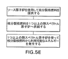
別の特徴では、エネルギー発生方法が開示されている。このエネルギー発生方法は、ソース原子炉を使って核分裂核燃料を増殖するステップと、その後、核分裂核燃料を1つ以上の熱スペクトル原子炉に供給するステップを含むことができる。次に、熱スペクトル原子炉は、オプションとして核分裂核燃料から利用可能なエネルギーを供給できる。 In another aspect, an energy generation method is disclosed. The energy generation method may include the steps of propagating fission nuclear fuel using a source reactor and then supplying the fission nuclear fuel to one or more thermal spectrum reactors. The thermal spectrum reactor can then optionally supply available energy from fission fuel.
以下の記載の一部には別の利点について記載し、更にこの記載から、利点の一部が明らかとなるか、または実施によりそれらの利点が理解できよう。特許請求の範囲に記載した要素およびそれらの組み合わせにより、別の利点について認識でき、得ることができよう。これまでの一般的な説明および下記の詳細な説明の双方は、単なる例示で、説明だけのものであり、請求項に記載した発明を限定するものではないと理解すべきである。
本明細書で援用し、明細書の一部をなす、必ずしも寸法どおりには描かれていない添付図面は、いくつかの図面を示すものであり、詳細な説明と共に本発明の原理を説明するよう働く。
Some of the following descriptions will describe other advantages, and from this description, some of the advantages will become apparent or may be understood by implementation. Other advantages may be recognized and obtained from the elements recited in the claims and combinations thereof. It is to be understood that both the foregoing general description and the following detailed description are exemplary only and are exemplary and are not restrictive of the invention as claimed.
The accompanying drawings, which are incorporated in and constitute a part of this specification and are not necessarily drawn to scale, illustrate several figures and together with the detailed description, illustrate the principles of the invention. work.
本願に記載のデバイス、システムおよび方法は、次の詳細な説明およびそれに含まれる実施例および図面、並びにこれより前の説明および次の説明を参照することにより、より容易に理解できよう。 The devices, systems, and methods described herein will be more readily understood by reference to the following detailed description and the examples and drawings contained therein, as well as the previous and following description.
本システム、物品、デバイスおよび/または方法を開示し、説明する前に、本発明は、当然ながら変更できる特定のシステム、特定のデバイスおよび特定の方法に本発明は限定されないと理解すべきである。更に、本願で使用する用語は、特定の実施形態だけを説明するためのものでなく、また限定するものでもないことも理解すべきである。 Before the present systems, articles, devices and / or methods are disclosed and described, it should be understood that the present invention is not limited to specific systems, specific devices and specific methods that can, of course, be modified. . Further, it is to be understood that the terminology used herein is not intended to describe the specific embodiments only, nor is it limiting.
本発明の次の説明は、現在知られている最良の実施形態において、本発明を実施可能に教示するものとして記載したものである。この目的のため、当業者であれば、本発明の有益な結果を得ながら、本願に記載の発明の種々の特徴について多くの変更を行うことができることも認識でき、かつ理解できよう。本発明の実施形態の他の特徴を利用することなく、本発明の実施形態の特徴の一部を選択することにより、本発明の所望する利点を得ることができることも明らかとなろう。従って、当業者であれば、本発明について多くの変形および適合を行うことが可能であり、所定の状況ではそのような変形および適合が望ましいこともあり、更に本発明の一部となっていることが認識できよう。従って、次の説明は本発明の原理を説明するものとして記載したものであり、発明を限定するものではない。 The following description of the present invention has been presented in the best known embodiment to teach the present invention to be operable. For this purpose, those skilled in the art will also recognize and understand that many changes can be made to the various features of the invention described herein while still obtaining the beneficial results of the invention. It will also be apparent that the desired advantages of the present invention can be obtained by selecting some of the features of the embodiments of the present invention without utilizing other features of the embodiments of the present invention. Accordingly, one of ordinary skill in the art will be able to make many variations and adaptations to the present invention, and such variations and adaptations may be desirable in certain situations and are further part of the present invention. You can recognize that. Accordingly, the following description is presented as illustrative of the principles of the present invention and is not intended to limit the invention.
本発明を実施したり、テストする際には、本願に記載した方法および物質に類似または均等な方法および物質を使用できるが、次に、これら方法および物質の例について説明する。 Although methods and materials similar or equivalent to those described herein can be used in the practice or testing of the present invention, examples of these methods and materials are now described.
本願全体にわたり、種々の刊行物を参考とする。特に明記しない限り、本発明が関連する技術状態をより完全に記述するよう、これら刊行物全体における開示を参考例として本願に援用する。これら参考例に基づくという意味で記述されている、参考例に含まれる資料に関し、本願では開示されている参考例を別々にかつ特別に援用する。本発明の日付は、従来の発明のために、かかる刊行物よりも先行しないとの自認したものと見なすべきでない。更に、本願に記載されている刊行物の日付が実際の刊行日と異なっていることがあり、この実際の刊行日は別個に確認する必要がある場合がある。 Throughout this application, various publications are referenced. Unless otherwise stated, the disclosures in these publications are incorporated herein by reference in their entirety to more fully describe the state of the art to which this invention pertains. With respect to the materials included in the reference examples described in the sense of being based on these reference examples, the reference examples disclosed herein are separately and specifically incorporated. The dates of the present invention should not be regarded as adhering to prior art because they do not precede such publications. Further, the dates of publications described herein may differ from the actual publication dates, which may need to be confirmed separately.
本明細書および添付した特許請求の範囲で使用するような単一形態「1つの」、「ある」および「その」は、文脈が反対のことを明瞭に規定しない限り、複数の対象を含む。従って、例えば「1つのダイバータ板」、「1つの原子炉」または「1つの粒子」なる記載は、かかるダイバータ板、原子炉または粒子などが2つ以上組み合わされていることも意味する。 As used herein and in the appended claims, the single forms “a”, “an”, and “its” include pluralities unless the context clearly dictates otherwise. Thus, for example, the description “one diverter plate”, “one nuclear reactor” or “one particle” also means that two or more such diverter plates, nuclear reactors or particles are combined.
本願では、ある特定の「およそ(ほぼ、約、概ね)」の値から別の特定の「およそ(ほぼ、約、概ね)」の値までのように、あるレンジを表記できる。かかる1つのレンジが表記されたとき、別の実施形態はこの1つの特定の値から、および/または別の特定の値までを含む。同様に、先行詞「約」を使用することにより、値が近似値として表記されているとき、この特定の値は別の実施形態をなすと理解できよう。更に、これらレンジの各々の端部ポイントは、他の端部ポイントに対し、かつ他の端部ポイントとは別個に、重要であることも理解できよう。本願で開示する値は、多数あり、各値は、本願では値自身の他に特定の値に「約」を付して開示されていることも理解できよう。例えば値「10」を開示する場合、「約10」も開示される。ある値が開示されているとき、当業者であれば適当に理解できるように、「この値以下」、「この値以上」およびこれら値の間の可能なレンジも含まれることも理解できよう。例えば、値「10」が開示されている場合、「10以下」だけでなく「10以上」も開示されている。本願全体にわたり、多数の異なるフォーマットでデータが記載されており、このデータは、終了ポイントおよび開始ポイント、並びにこれらデータポイントの任意の組み合わせに対するレンジも示すことも理解できよう。例えば、特定のデータポイント「10」および特定のデータポイント「15」が開示されている場合、10および15より大、10および15以上、10および15未満、10および15以下、および10および15に等しい値だけでなく、10から15の間も開示されていると見なされる。2つの特定の単位の間の各単位も開示されていると理解できよう。例えば10および15が開示されている場合、11、12、13および14も開示されている。 In this application, a range can be expressed as from one particular “approximately (approximately, approximately, approximately)” value to another particular “approximately (approximately, approximately, approximately)” value. When such a range is expressed, another embodiment includes from this one particular value and / or to another particular value. Similarly, by using the antecedent “about”, when a value is expressed as an approximation, it will be understood that this particular value forms another embodiment. It will further be appreciated that the end points of each of these ranges are important relative to the other end points and independent of the other end points. It should be understood that there are many values disclosed in the present application, and that each value is disclosed by adding “about” to a specific value in addition to the value itself in the present application. For example, if the value “10” is disclosed, “about 10” is also disclosed. When a value is disclosed, it will also be understood that “below this value”, “above this value” and possible ranges between these values are also included, as will be appreciated by those skilled in the art. For example, when the value “10” is disclosed, not only “10 or less” but also “10 or more” is disclosed. It will also be appreciated that throughout the application, the data is described in a number of different formats, and this data also indicates the end and start points and the range for any combination of these data points. For example, if a specific data point “10” and a specific data point “15” are disclosed, greater than 10 and 15, 10 and 15 or more, less than 10 and 15, 10 and 15 or less, and 10 and 15 Between 10 and 15 is considered to be disclosed as well as equal values. It will be understood that each unit between two specific units is also disclosed. For example, if 10 and 15 are disclosed, 11, 12, 13 and 14 are also disclosed.
本願で使用するように、「オプションの」または「オプションとして」なる用語は、後に記述する特徴が存在し得ること、または存在しないこと、または後に記述する事象または状況が生じ得ること、または生じないこと、および前記事象または状況が生じる場合および前記事象または状況が生じない場合を記載が含むことを意味する。例えば開示する実施形態が、オプションとして核融合プラズマを含むことができる場合、核融合プラズマは存在していてもよいし、存在していなくてもよい。 As used herein, the term “optional” or “optionally” means that the features described below may or may not exist, or that the events or situations described below may or may not occur. And the description includes when the event or situation occurs and when the event or situation does not occur. For example, if the disclosed embodiments can optionally include a fusion plasma, the fusion plasma may or may not be present.
本願で使用する場合の「例示した」なる用語は、「〜の一例」を意味し、好ましい実施形態もしくは理想的な実施形態を伝えるものではない。更に、本願で使用する「〜のような」または「例えば」なるフレーズは、いかなる意味においても限定的なものではなく、単に説明のためのものであり、記載したアイテムがこの記載によってカバーされるものの例であることを示すように使用したものである。 The term “exemplified” as used herein means “an example of” and does not convey a preferred or ideal embodiment. Furthermore, the phrases “such as” or “for example” as used herein are not limiting in any way and are merely illustrative and the items described are covered by this description. It is used to show that it is an example of a thing.
組成物を調製するために使用すべき成分だけでなく、本願で開示する方法で使用すべき組成物自体も開示されている。本願では、これら物質およびその他の物質も開示されており、これら物質のうちの組み合わせ、サブセット、相互作用、グループなどが開示されるとき、これら化合物の種々の各組み合わせおよび総合的な組み合わせ、およびこれら化合物の置換の特定の基準を明示的に開示できないが、各々を特別に考え、本願に記載する。例えば特定の化合物が開示され、記載され、化合物を含む多数の分子とすることができる多数の変形例が記載されている場合、特に逆のことが示されない限り、化合物および可能な変形例の各組み合わせおよび置換のいずれも、すべて特別に考えつくことができる。従って、あるクラスの成分A、BおよびCだけでなく、あるクラスの成分D、EおよびFも開示され、更に、組み合わせ成分A〜Dの一例も開示されている場合、各々が個々に記載されていなくても、各々を個々に、かつ集合的に考えつくことができる。すなわち組み合わせA〜E、A〜F、B〜D、B〜E、B〜F、C〜D、C〜EおよびC〜Fも開示されているものと見なすことができる。従って、例えばA〜E、B〜FおよびC〜Fのサブグループも開示されているものと見なされる。この概念は、組成物を製造し、使用する方法におけるステップを含む(これらステップだけに限定されない)本願のすべての要素にも当てはまる。従って、実行できる種々の追加ステップが存在する場合、本発明の任意の特定の実施形態またはこれら実施形態の組み合わせと共に、これら追加ステップの各々を実施できることも理解できよう。 Not only are the ingredients to be used to prepare the composition, but the compositions themselves to be used in the methods disclosed herein are also disclosed. The present application also discloses these and other substances, and when combinations, subsets, interactions, groups, etc. of these substances are disclosed, various combinations and overall combinations of these compounds, and Although specific criteria for substitution of compounds cannot be explicitly disclosed, each is specifically considered and described herein. For example, if a particular compound is disclosed and described, and numerous variations are described that can be multiple molecules containing the compound, each of the compounds and possible variations unless indicated to the contrary. All combinations and substitutions can all be specially conceived. Thus, when not only a class of components A, B and C, but also a class of components D, E and F are disclosed, and further examples of combination components AD are disclosed, each is individually described. Even if not, each can be thought of individually and collectively. That is, combinations A to E, A to F, B to D, B to E, B to F, C to D, C to E, and C to F can also be regarded as disclosed. Thus, for example, the sub-groups A-E, B-F, and C-F are also considered disclosed. This concept also applies to all elements of the present application including, but not limited to, steps in methods of making and using the composition. Thus, it will also be understood that each of these additional steps can be implemented with any particular embodiment or combination of embodiments of the present invention, where there are various additional steps that can be performed.
本願に開示された組成物は、所定の機能を有すると理解できよう。本願には、開示された機能を奏するための所定の構造的条件が開示されており、開示された構造に関連する同じ機能を奏することができる構造が種々存在すること、およびこれら構造は、一般に同じ結果を得ることができると理解できよう。 It will be understood that the compositions disclosed herein have a predetermined function. This application discloses certain structural conditions for performing the disclosed functions, and there are various structures that can perform the same functions related to the disclosed structures, and these structures are generally It will be understood that the same result can be obtained.
核燃料を増殖するための原子炉、プラズマまたは核融合プラズマを収納するための容器、核融合中性子ソースおよびトカマクが開示されており、ここでは、内部にオプションとして反応性プラズマが存在でき、前記プラズマの少なくとも一部または前記プラズマを収納するためのチャンバに、核燃料親物質が実質的に隣接する。開示された実施形態を使用して、核燃料親物質を核分裂物質に変換する方法も開示されており、これら方法では、反応性プラズマが存在する。利用可能なエネルギーを抽出するのに利用できる核燃料を増殖するための各燃料サイクルも開示されており、開示された実施形態および1つ以上の熱スペクトル原子炉を含む原子炉ネットワークも開示されている。 A nuclear reactor for propagating nuclear fuel, a vessel for containing plasma or fusion plasma, a fusion neutron source and a tokamak are disclosed, in which a reactive plasma can optionally be present, A nuclear fuel parent material is substantially adjacent to at least a portion or a chamber for containing the plasma. Also disclosed are methods for converting nuclear fuel parent material to fission material using the disclosed embodiments, wherein a reactive plasma is present. Each fuel cycle for propagating nuclear fuel that can be utilized to extract available energy is also disclosed, and a reactor network including the disclosed embodiments and one or more thermal spectrum reactors is also disclosed. .
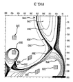
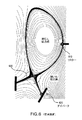
一例として、開示された実施形態は、図1および2に示されるような一般的構造を有することができ、これら図は、開示された原子炉100の半分の横断面図となっている。図1に示されるように、開示された実施形態は、中心軸線250を中心として壁170によって実質的に囲まれたトロイダルチャンバを含むことができる。このチャンバの壁は、中心軸線250に最も近い内側半径240と、中心軸線250から最も遠い外側半径230とを有する。トロイダルチャンバは、オプションとしてコアプラズマ160を含むことができ、このコアプラズマ160は、存在するときに、コアプラズマに対して閉じた磁気表面180および開いた磁力線260により、前記トロイダルチャンバ内に収納できる。このコアプラズマは、核融合反応により高速(約1千400万電子ボルト)の中性子を発生でき、この中性子は帯電していないので、所定の軌跡を通ってコアプラズマから離間できる。これら中性子は、存在するときに、前記コアプラズマ160の少なくとも一部に実質的に隣接する核分裂可能な物質150の層に衝突できる。原子炉を中性子からインシュレートするために、原子炉の一部はPbセクション290を含むことができる。更に、核分裂可能な物質150の層をPbシース110が実質的に囲むことができる。トロイダル磁場(TF)コイル280および220だけでなく、ポロイダル磁場(PF)コイル120、140、190および210(これらだけに限定されない)も含む電流搬送導線により誘導される電流によって、開いた磁力線および閉じた磁力線180を発生できる。開いた磁力線260と閉じた磁力線180との間にメイン境界、すなわちセパラトリックス270が存在できる。すなわち開いた磁気ドリフト軌跡と閉じた磁気ドリフト軌跡との間に境界が存在できる。開いた磁力線260により、1つ以上のダイバータ板130および200へ、閉じた磁気表面180を横断する粒子、熱および/またはエネルギー(すなわち交差磁場フラックス)を向けることができる。
As an example, the disclosed embodiments can have a general structure as shown in FIGS. 1 and 2, which are half cross-sectional views of the disclosed
1つの特徴では、大パワー密度中性子ソースをコアプラズマまたは各融合プラズマとすることができ、このプラズマは核燃料親物質が前記中性子を吸収し、その少なくとも一部が核分裂物質に変換されるよう、プラズマから中性子を放出する。一特徴では、核分裂性物質のかかる反応は、(例えば中性子を吸収することにより)前記核燃料親物質を核分裂物質に変換できる。かかる核分裂物質は、利用可能なエネルギーを発生するように、オプションとして更に分裂できる。 In one aspect, the high power density neutron source can be a core plasma or each fusion plasma, which is a plasma such that the nuclear fuel parent material absorbs the neutron and at least a portion thereof is converted to fission material. Emits neutrons. In one aspect, such a reaction of a fissile material can convert the nuclear fuel parent material to a fission material (eg, by absorbing neutrons). Such fissile material can optionally be further split to generate available energy.
別の特徴では、第1チャンバ内に実質的に閉じ込められたプラズマは、全加熱パワー、すなわち外部ソースと熱核ソースの双方を含むすべてのソースからの加熱パワーを有することができるので、全加熱パワーをプラズマのメジャー半径で割った値は、毎秒1m当たり30メガワット以上となる。更に別の特徴では、実質的に閉じ込められたプラズマは、プラズマの表面を横断する、毎秒1平方メートル当たり約0.1メガワット以上に等しい平均全中性子パワーを発生できる。「平均全中性子パワー」なる用語は、平均パワーを生じるように一定の時間にわたって原子炉の中性子パワーを平均化できることを意味する。例えば開示する全中性子パワーとは、1つの特徴では、1年にわたって平均された全中性子パワーを意味し得る。別の特徴では、平均時間を1年未満とすることができる。 In another feature, the plasma substantially confined in the first chamber can have a total heating power, i.e. a heating power from all sources including both external and thermonuclear sources, so The value obtained by dividing the power by the major radius of the plasma is 30 megawatts or more per meter per second. In yet another feature, the substantially confined plasma can generate an average total neutron power equal to greater than about 0.1 megawatts per square meter per second across the surface of the plasma. The term “average total neutron power” means that the neutron power of the reactor can be averaged over a period of time to produce an average power. For example, disclosed total neutron power may mean, in one aspect, total neutron power averaged over a year. In another feature, the average time can be less than one year.
一特徴では、開いた、または閉じた核燃料サイクルで開示した実施形態を使用できる。フロントエンドステップと一般に称されるものでは、核燃料親物質を核分裂物質に変換する大パワー密度の中性子ソースを使用して、核燃料を製造できる。次に、サービス時間と称される時間の間、利用可能なエネルギーを抽出するように、核分裂物質を更に分裂させることができる。サービス時間ステップが燃料サイクルの最終ステップである場合、燃料サイクルは開放された閉サイクルとなる。しかしながら、サービス時間からの生成物、廃棄物および同等物を更に処理するバックエンドステップ中に、更なるステップを実行できることが明らかとなろう。サービス時間からの生成物をバックリサイクルするために更なるステップを実行する場合、この燃料サイクルは、閉じた燃料サイクルとなる。例えば一実施形態では、開示した核融合原子炉へサービス時間からの副生成物をリサイクルすることができ、本願で全体を参考例として援用し、その一部となす、2008年9月11日に出願されたコッツェンロイター外を発明者とする米国特許出願第12/208532号に開示されている実施形態および方法を通して、廃棄物を原子力利用でない物質に変換できる。開示した実施形態を使用すると、開いた燃料サイクルまたは閉じた燃料サイクルのいずれかを実施できる。 In one aspect, the disclosed embodiments can be used with open or closed nuclear fuel cycles. In what is commonly referred to as a front-end step, nuclear fuel can be produced using a high power density neutron source that converts nuclear fuel parent material to fission material. The fissile material can then be further split to extract available energy during what is referred to as service time. If the service time step is the final step of the fuel cycle, the fuel cycle becomes an open closed cycle. However, it will be apparent that further steps can be performed during the back-end step of further processing product, waste and equivalent from service time. This fuel cycle becomes a closed fuel cycle when further steps are taken to back recycle the product from service time. For example, in one embodiment, by-products from service time can be recycled to the disclosed nuclear fusion reactor, which is hereby incorporated by reference in its entirety and made a part thereof, on September 11, 2008 Through the embodiments and methods disclosed in US patent application Ser. No. 12/208532, inventor filed outside Kotzenreuter, waste can be converted to non-nuclear material. Using the disclosed embodiments, either an open fuel cycle or a closed fuel cycle can be implemented.
更に別の特徴では、開示された原子炉から生じた核分裂物質(すなわち増殖された核燃料)を1つ以上の熱中性子スペクトル原子炉(例えば軽水型原子炉(LWR))または利用できるエネルギーを抽出するために核分裂物質を分裂させることができる他の原子炉に送ることができる。 In yet another aspect, fission material (ie, propagated nuclear fuel) resulting from the disclosed nuclear reactor is extracted from one or more thermal neutron spectrum nuclear reactors (eg, light water reactors (LWR)) or available energy. Can be sent to other nuclear reactors that can split the fission material.
従って、一特徴では、開示された原子炉および1つ以上の熱スペクトル原子炉を含む原子炉シリーズも提供される。1つの特徴では、開示された原子炉と1つ以上の熱スペクトル原子炉は、ネットワーク内で機能する。例えば開示された中性子ソース原子炉から生じた核分裂核燃料を1つ以上の熱スペクトル原子炉へ供給できる。次に、公知の方法、例えば核燃料を分裂させる方法を使用して、この核分裂燃料を1つ以上の熱スペクトル原子炉によって処理できる。1つの特徴では、ソース原子炉によって供給される核分裂性核燃料から利用可能なエネルギーを抽出できる。別の特徴では、開示されたソース原子炉は、単独で複数の熱スペクトル原子炉に燃料を供給し、ソース原子炉と前記複数の熱スペクトル原子炉とのサポート比を大きくする。 Accordingly, in one aspect, a nuclear reactor series including the disclosed nuclear reactor and one or more thermal spectrum nuclear reactors is also provided. In one aspect, the disclosed nuclear reactor and one or more thermal spectrum nuclear reactors function in a network. For example, fission fuel produced from the disclosed neutron source reactor can be supplied to one or more thermal spectrum reactors. The fission fuel can then be processed by one or more thermal spectrum reactors using known methods, such as a method of splitting nuclear fuel. In one aspect, the available energy can be extracted from the fissile nuclear fuel supplied by the source reactor. In another aspect, the disclosed source reactor supplies fuel to multiple thermal spectrum reactors alone to increase the support ratio between the source reactor and the multiple thermal spectrum reactors.
本願で使用する「核燃料親物質」なる用語は、一般にそれ自体が誘導された核分裂を受けていない(熱中性子によって分裂可能な)核種であって、中性子の吸収およびその後の核の変換を通して核分裂物質を発生できる核種を記述するのに使用する用語である。大パワー密度中性子ソースから生じる中性子に照射によって核分裂物質に変換できる、自然に生じた核燃料親物質として、ウラン233(U233)も変わるトリウム232(Th232)、ウラン235(U235)に変わるウラン234(U234)、およびプルトニウム239(Pu239)に変わるウラン238(U238)が挙げられるが、これらだけに限定されるものではない。1つの中性子を捕獲することによって核分裂物質に変換できる、原子炉内で形成される人工アイソトープとして、プルトニウム239(Pu239)に変わるプルトニウム238(Pu238)およびプルトニウム241(Pu241)に変わるプルトニウム240(Pu240)が挙げられるが、これらだけに限定されない。
As used herein, the term “nuclear fuel parent material” is generally a nuclide that is not itself subjected to fission (it can be split by thermal neutrons), and through fission material absorption and subsequent nuclear transformation, Is a term used to describe nuclides that can generate As a naturally occurring nuclear fuel parent material that can be converted to fission material by irradiation of neutrons generated from a high power density neutron source, uranium 233 (U 233 ) also changes uranium 232 (Th 232 ), uranium changes to uranium 235 (U 235 ) 234 (U 234 ), and uranium 238 (U 238 ) instead of plutonium 239 (Pu 239 ), but are not limited thereto. As artificial isotopes formed in a nuclear reactor that can be converted into fission material by capturing one neutron, plutonium 238 (Pu 238 ) instead of plutonium 239 (Pu 239 ) and
他のアクチニド系列は、核分裂性であり、かつ別の中性子を捕獲し、崩壊ではなく核分裂できるのに充分超寿命であるアイソトープに変わる前に、2つ以上の中性子を捕獲しなければならない。例えばプルトニウム242(Pu242)は、アメリシウム243(Am243)に変換され、次にキュリウム244(Cm244)に変換され、次にキュリウム245(Cm245)に変換され得る。別の例では、ウラン236(U236)は、ネプツニウム237(Np237)に変換され、次にプルトニウム238(Pu238)に変換され、次にプルトニウム239(Pu239)に変換される。 Other actinide series must capture two or more neutrons before they are fissile and capture another neutron and change to an isotope that is long-lived enough to allow fission rather than decay. For example, plutonium 242 (Pu 242 ) can be converted to americium 243 (Am 243 ), then converted to curium 244 (Cm 244 ), and then to curium 245 (Cm 245 ). In another example, uranium 236 (U 236 ) is converted to neptunium 237 (Np 237 ), then converted to plutonium 238 (Pu 238 ), and then converted to plutonium 239 (Pu 239 ).
従って、1つの特徴では、第2チャンバは、核燃料親物質、例えば上記のような核燃料親物質を含むことができ、増殖反応が生じた場合、第2チャンバは更に核分裂物質(すなわち中性子を捕獲したときに増殖された核燃料親物質の生成物)を更に含むことができる。この核分裂物質は、上記のような物質でもよいし、上記以外の核分裂物質でもよい。特定の特徴では、第2チャンバがTh232を含むようなトリウム燃料サイクルで、開示された実施形態を使用できる。Th232が核燃料、すなわち核分裂物質に変換された場合、第2チャンバは更にU238を含むことができる。1つの特徴では、第2チャンバはTh232とU238の混合物を含むことができるので、現場で増殖されたU233が変性される(すなわちU238により充分に希釈される)。 Thus, in one aspect, the second chamber can contain a nuclear fuel parent material, eg, a nuclear fuel parent material as described above, and if a growth reaction occurs, the second chamber further captures fission material (ie, neutrons). (Sometimes propagated products of nuclear fuel parent material). This fission material may be a material as described above, or a fission material other than the above. In particular features, the disclosed embodiments can be used with a thorium fuel cycle in which the second chamber includes Th 232 . If Th 232 is converted to nuclear fuel, i.e., fission material, the second chamber may further include U238 . In one aspect, the second chamber can contain a mixture of Th 232 and U 238 so that U 233 grown in situ is denatured (ie, sufficiently diluted by U 238 ).
1つの特徴では、第2チャンバ内の核分裂物質は、兵器グレード、すなわち兵器に利用できる核物質として分離するのに充分な程度に濃縮されるわけではない。しかしながら、例えばトリウムサイクルの使用により、解消されないにしても、兵器への転換または兵器への流用の恐れを最小にできることが明らかとなろう。今日までU233から兵器に利用できるか、または兵器グレードの物質を製造した国はない。しかしながら、所望すれば、U233をU238で充分に希釈でき、その混合物は濃縮されたU233へ戻すのに容易に処理することができないので、兵器への流用の恐れはない。別の特徴では、核増殖方法は、Puを発生させる場合、現場でPuを燃焼させることができ、Puは核増殖プラントから外に出ることはないはずである。 In one aspect, the fissile material in the second chamber is not enriched enough to separate as weapon grade, ie, nuclear material available to the weapon. However, it will be clear that the use of a thorium cycle, for example, can minimize the risk of conversion or diversion to weapons if not eliminated. To date, no country has made weapon grade material available from U 233 or weapon grade. However, if desired, U 233 can be sufficiently diluted with U 238 and the mixture cannot be easily processed back into concentrated U 233 so there is no fear of diversion to weapons. In another aspect, when the nuclear proliferation method generates Pu, it can burn Pu in situ and Pu should not leave the nuclear proliferation plant.
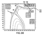
大パワー密度中性子ソースは、例えば図3に示されるような磁気的幾何学的形状およびコイルとダイバータのコンフィギュレーションを有することができ、図3は、CORSICA TMコンピュータプログラムによって発生されるトロイダル原子炉のセクションの横断面図である。このCORISICA TMとは、磁気核融合炉内の物理プロセスをシミュレートするために、カリフォルニア州リバモアのローレンスリバモア国立研究所によって開発されたソフトウェアである。この実施形態では、プラズマ310は、閉じた磁気表面340によって主にプラズマ310を閉じ込めることができ、前記閉じた磁気表面を越えてスクレイプオフ層(SOL)300が存在する。プラズマ310を中心とする閉じた磁気表面340(すなわちトロイダル磁場)は、実質的にトロイダル構造体の中心を実質的に通過するトロイダル磁場(TF)コイルまたは導線(図示せず)により、プラズマ310内に誘導された電流によって生じ、よって当業者が知るように、トランスの作用によりプラズマ310内に電流を誘導する。SOL300は、(核融合プラズマの閉じた磁気表面340に対し)開いた磁力線を含むことができる。壁350により真空チャンバ345を実質的に囲むことができる。前記真空チャンバの外側には別の磁力線370が存在することができる。開いた磁力線を生じさせる磁場(すなわちポロイダル磁場(PF))を発生するのに、壁350内または壁350に隣接するコイル320、すなわち電流搬送導線を使用できる。磁力線を整形および制御する必要がある場合、前記コイル320または電流搬送導線が磁力線を整形および/または制御でき、磁場横断フラックス(またはスクレイプオフフラックス)をダイバートするための開いた磁力線を形成できる。すなわち核融合プラズマ310から閉じた磁力線340を横断し、開いた磁力線まで移動する粒子を形成できる。開いた磁力線により、スクレイプオフフラックスを図3に示されているようなダイバータ板330にダイバートでき、オプションとして核融合プラズマ310から放出される中性子からダイバータ板330をシールドできる。ダイバータ板330は、核融合プラズマ310からラジアル距離(直線の距離)にあると共に、当技術で見られる他の核融合炉より大きい磁気距離(核融合プラズマからダイバータ板までの磁力線に沿った距離)にあるので、ダイバータ板において、開いた磁力線を更に広げることができ、よってダイバータ板330での熱の集中を緩和し、核融合プラズマから離間してダイバータ板330に到着するまでの粒子のラジアント冷却を可能にできる。この実施形態では、前記プラズマ310および/または前記プラズマを閉じ込めるための前記真空チャンバ345の少なくとも一部に、核燃料親物質を含む第2チャンバ(図示せず)を実質的に隣接させることができる。本開示から明らかとなるように、この実施形態について種々の変形を行うことができる。
A high power density neutron source can have a magnetic geometry and coil and diverter configuration as shown, for example, in FIG. 3, which is a toroidal reactor generated by the CORSICA ™ computer program. It is a cross-sectional view of a section. The CORISICA ™ is software developed by Lawrence Livermore National Laboratory, Livermore, California, to simulate physical processes in a magnetic fusion reactor. In this embodiment, the
核燃料を増殖するための原子炉は、核融合と両立できる任意の容器を含むことができ、必ずしも公知の容器構造に限定されない。反応性プラズマが存在する場合、プラズマを収納するための容器を核融合中性子ソースとすることができる。反応性プラズマが存在する場合、プラズマを収納するための容器を核融合中性子ソースとすることができる。プラズマを収納するための容器は、トカマクでもよい。文脈が明瞭に否定しない限り、プラズマ、核融合プラズマ、核融合中性子ソースまたはトカマクを閉じ込めるための開示した容器、またはこの容器からの熱を排出するための方法と共に、開示した任意の構成部品または実施形態を使用できると理解されよう。 A nuclear reactor for propagating nuclear fuel can include any vessel compatible with nuclear fusion and is not necessarily limited to a known vessel structure. If reactive plasma is present, the vessel for containing the plasma can be a fusion neutron source. If reactive plasma is present, the vessel for containing the plasma can be a fusion neutron source. The container for storing the plasma may be a tokamak. Unless the context clearly dictates, any disclosed component or implementation along with the disclosed container for confining a plasma, fusion plasma, fusion neutron source or tokamak, or a method for exhausting heat from this container It will be understood that the form can be used.
1つの特徴では、第1チャンバは、中心軸線を中心とし、壁によって実質的に囲まれたトロイダルチャンバとすることができ、このトロイダルチャンバは中心軸線に対する内径と外径とを有し、開示される実施形態は、磁場によってトロイダルチャンバ内に実質的に収納された核融合プラズマから排出熱を受けるためのダイバータ板を更に含むことができ、このダイバータ板は、中心軸に対するダイバータ径を有し、このダイバータ径は、少なくともトロイダルチャンバの内径以上となっている。核燃料親物質を含む第2チャンバを核融合プラズマに実質的に隣接させることができる。 In one aspect, the first chamber can be a toroidal chamber centered about a central axis and substantially surrounded by a wall, the toroidal chamber having an inner diameter and an outer diameter with respect to the central axis. Embodiments can further include a diverter plate for receiving exhaust heat from a fusion plasma substantially contained within the toroidal chamber by a magnetic field, the diverter plate having a diverter diameter relative to a central axis; The diverter diameter is at least larger than the inner diameter of the toroidal chamber. The second chamber containing the nuclear fuel parent material can be substantially adjacent to the fusion plasma.
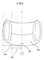
本願で使用するように、「中心軸」とは、ある平面内にあり、開示される実施形態のセントロイド(質量中心)を通過する軸を意味する。図4には、例えば中心軸を囲む容器の一部が示されている。容器410の一部が中心軸420を囲んでいる。外側に延び、前記中心軸に実質的に直交する空間内のポイントは前記中心軸に対する半径を有する。例えば前記中心軸420に最も近い内径430と、前記中心軸420から最も遠い外径440とを有することができる。1つの特徴によれば、前記内径および前記外径は、前記中心軸420に実質的に直交し、前記容器の直径と同じx−y−z平面に沿って位置するポイントとして定めることができる。
As used herein, a “central axis” means an axis that lies in a plane and passes through the centroid (center of mass) of the disclosed embodiments. FIG. 4 shows a part of the container surrounding the central axis, for example. A part of the
開示されるチャンバは、核融合プラズマを閉じ込めるためのコンパーチブルな(両立性のある)任意の形状とすることができる。一部の特徴によれば、開示されるチャンバの少なくとも一部をトロイダル状としてもよい。「トロイダル」とは、中心軸上のポイントを中心として回転すると、トロイダル回転となることを意味する。従って、開示されるチャンバ全体がトロイダル状でなくてもよく、ある中心軸を中心として回転すると、前記チャンバ内のポイントまたは前記チャンバ上のポイントがトロイダル形状を生じさせればよい。 The disclosed chamber can be any compatible (compatible) shape for confining the fusion plasma. According to some features, at least a portion of the disclosed chamber may be toroidal. “Toroidal” means toroidal rotation when rotated about a point on the central axis. Thus, the entire disclosed chamber may not be toroidal, and as long as it rotates about a central axis, a point in the chamber or a point on the chamber will produce a toroidal shape.
1つの特徴によれば、開示される容器は、核融合炉とコンパーチブルにすべき任意の物質を含むことができる。限定しない例として、金属(例えばタングステンおよびスチール)、金属合金、カーボン複合体を含む複合体、それらの組み合わせおよび同等物が挙げられる。 According to one feature, the disclosed vessel can contain any material that is to be compatible with the fusion reactor. Non-limiting examples include metals (eg, tungsten and steel), metal alloys, composites including carbon composites, combinations thereof, and the like.
1つの特徴によれば、開示される実施形態は、改良されたダイバータを含む。本願で使用するような「ダイバータ」とは、コアプラズマから離間する任意の位置へ熱、エネルギーおよび/または粒子をダイバートする実施形態内のすべての特徴を意味する。ダイバータの特徴の例として、スクレイプオフ層、スクレイプオフフラックスを内部に収納する開いた磁力線、1つ以上のダイバータ板(またはダイバータターゲット)、および1つ以上のセパラトリックスを挙げることができるが、これらに限定されない。 According to one feature, the disclosed embodiments include an improved diverter. “Diverter” as used herein refers to all features in the embodiment that divert heat, energy and / or particles to any location spaced from the core plasma. Examples of divertor features may include a scrape-off layer, an open magnetic field line that houses the scrap-off flux, one or more diverter plates (or diverter targets), and one or more separatrix. It is not limited to.
1つの特徴によれば、前記ダイバータ板は、核融合炉と共に使用するのに適した任意の物質を含むことができる。現在存在する公知のダイバータの組成物、例えばCuまたは炭素複合体上に設けられたタングステンまたはタングステン複合体を使用できる。その他の使用できる物質として、高熱伝導率基板上に設けられたスチール合金が挙げられる。 According to one feature, the diverter plate can comprise any material suitable for use with a fusion reactor. Currently known diverter compositions can be used, such as tungsten or tungsten composites provided on Cu or carbon composites. Other usable materials include steel alloys provided on high thermal conductivity substrates.
別の特徴によれば、ダイバータ板は、中心軸に対するダイバータ半径を有することができ、このダイバータ半径は、別の構成部品に対する位置または開示された実施形態内のポイントに位置できる。当業者であれば理解できるように、他の構成部品、例えばプラズマまたはチャンバ壁などに対するダイバータ半径の比は、適当な個々の任意の半径を含むようになっている。従って、開示される実際の任意のダイバータ半径は、純粋に例にすぎず、限定的なものではない。 According to another feature, the diverter plate can have a diverter radius relative to the central axis, which can be located at a position relative to another component or at a point within the disclosed embodiments. As will be appreciated by those skilled in the art, the ratio of the divertor radius to other components, such as plasma or chamber walls, is intended to include any suitable individual radius. Thus, any actual diverter radius disclosed is purely exemplary and not limiting.
本願で使用し、Rdivと示される用語「ダイバータ半径」とは、ダイバータ板の、中心軸から最も遠い半径の長さを意味する。 The term “divertor radius” used in the present application and indicated as R div means the length of the radius farthest from the central axis of the diverter plate.
1つの特徴によれば、ダイバータ板は、トロイダルチャンバの外径以上のダイバータ半径を有することができる。別の特徴では、ダイバータ板は、トロイダルチャンバの外径以下のダイバータ半径を有することができる。更に別の特徴では、ダイバータ板は、トロイダルチャンバの内径以上のダイバータ半径を有することができる。 According to one feature, the diverter plate can have a diverter radius greater than or equal to the outer diameter of the toroidal chamber. In another feature, the diverter plate can have a diverter radius that is less than or equal to the outer diameter of the toroidal chamber. In yet another feature, the diverter plate can have a diverter radius greater than or equal to the inner diameter of the toroidal chamber.
1つの特徴では、トロイダルチャンバの外径Rcに対するダイバータ半径Rdivの比は、約0.1〜約10、または約0.5〜約8、または約1〜約6、または約1〜約5、または約1〜約3、または約1〜約1.5でよい。 In one aspect, the ratio of the divertor radius R div to the toroidal chamber outer diameter R c is about 0.1 to about 10, or about 0.5 to about 8, or about 1 to about 6, or about 1 to about 5, or about 1 to about 3, or about 1 to about 1.5.
一般に、任意のサイズの実施形態を使用することが可能である。しかしながら、例えば前記ダイバータ板は、約0.2m、0.5m、1m、1.5m、2m、3m、4m、5m、6m、7m、8m、9m、または10mの半径を有することができる。別の特徴では、ダイバータ半径を約1.9m、3.3m、4m、7.3mまたは7.5mとすることができる。 In general, any size embodiment can be used. However, for example, the diverter plate can have a radius of about 0.2 m, 0.5 m, 1 m, 1.5 m, 2 m, 3 m, 4 m, 5 m, 6 m, 7 m, 8 m, 9 m, or 10 m. In another feature, the divertor radius can be about 1.9 m, 3.3 m, 4 m, 7.3 m, or 7.5 m.
1つの特徴では、ダイバータ板はセパラトリックス上のXポイントに対するダイバータ半径を有することができる。本願で使用する「セパラトリックス」なる用語は、開いた磁気表面と閉じた磁気表面との間の境界を意味し、Xポイントとは、ポロイダル磁場がゼロとなるセパラトリックス上のポイントを意味する。1つの特徴では、開示される実施形態では多数のXポイントが存在し、メインプラズマのXポイントは、前記コアプラズマに隣接するXポイントを意味する。例えば再び図3を参照すると、メインXポイントは、番号360で示されている。メインXポイントの半径は、一般に磁力線のコンフィギュレーションによって決まる。1つの特徴では、ダイバータ板は、メインXポイントの半径以上の主半径を有することができる。
In one feature, the diverter plate can have a divertor radius relative to the X point on the separatrix. As used herein, the term “separatrix” refers to the boundary between an open magnetic surface and a closed magnetic surface, and the X point refers to a point on the separatrix where the poloidal magnetic field is zero. In one aspect, there are multiple X points in the disclosed embodiment, and the X point of the main plasma refers to the X point adjacent to the core plasma. For example, referring again to FIG. 3, the main X point is indicated by the
1つの特徴では、Xポイントの半径に対するダイバータ板の半径の比、Rdiv/RXを約1〜約5、または約1〜約4、または約1〜約3.5、または約1.5〜約3.5とすることができる。例えば開示されるダイバータ板および開示されるセパラトリックスは、対応する比と共に表1にリストされる半径を有することができる。 In one aspect, the ratio of the radius of the divertor plate to the radius of the X point, R div / R X is about 1 to about 5, or about 1 to about 4, or about 1 to about 3.5, or about 1.5. To about 3.5. For example, the disclosed divertor plates and the disclosed separatrix can have the radii listed in Table 1 with corresponding ratios.
表1.RdivおよびRXの例

更に別の特徴では、ダイバータ板は、前記中心部から前記プラズマ中心までの距離として定義される、プラズマメジャー半径に対するダイバータ半径を有することができる。例えばプラズマのメジャー半径(R)に対するダイバータの半径の比、すなわちRdiv/Rを、例えば0.5、1、2、3、4、5、6、7、8、9、または10を含む、約0.5〜10、または約1〜8、または約1〜6、または約1〜5、または約2〜5とすることができる。限定されない特定の例として、プラズマメジャー半径が1mであり、ダイバータ半径が2mである場合、Rdiv/R=2となる。 In yet another feature, the diverter plate can have a divertor radius relative to a plasma major radius, defined as a distance from the center to the plasma center. For example, the ratio of the divertor radius to the major plasma radius (R), ie, R div / R, for example including 0.5, 1, 2, 3, 4, 5, 6, 7, 8, 9, or 10. It can be about 0.5-10, or about 1-8, or about 1-6, or about 1-5, or about 2-5. As a specific non-limiting example, if the plasma major radius is 1 m and the divertor radius is 2 m, then R div / R = 2.
1つの例では、前記ダイバータ板を、コアプラズマから放出される中性子から少なくとも部分的にシールドできる。別の特徴では、前記チャンバは、例えば図3に示されるように前記コアプラズマから放出される中性子からダイバータ板を少なくとも部分的にシールドする。 In one example, the diverter plate can be at least partially shielded from neutrons emitted from the core plasma. In another feature, the chamber at least partially shields the diverter plate from neutrons emitted from the core plasma, for example as shown in FIG.
中性子フラックスは、中性子放射線の強度の尺度であり、単位は中性子数/cm2・秒である。すなわち中性子フラックスは、1秒当たり所定のターゲットの1cm2を通過する中性子の数である。本願に記載されるダイバータ板の実施形態を使用すると、計算によれば、他のダイバータ板構造と比較して中性子フラックスが10倍以上減少することが分かる。
Neutron flux is a measure of the intensity of neutron radiation, and its unit is the number of neutrons / cm 2 · sec. That is, the neutron flux is the number of neutrons that pass 1
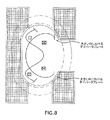
開示されるダイバータ板と組み合わせて、本願に開示される半径に対応しない別のダイバータ板も使用できる。より詳細に説明すれば、公知の原子炉構造は、半径がチャンバの外径未満、すなわちプラズマのメジャー半径となっているダイバータ板と、セパラトリックスまたは核融合プラズマを収納するための容器内の別の構成部品またはポイントを含むことができる。一部の特徴では、これら公知の構造は、別の開示されるダイバータ構造と共に単に大きくすることができる。かかるダイバータの例として、本願に開示される標準的なダイバータおよびコッツェンロイター外著、「熱負荷、新規なダイバータおよび核融合炉について」、フィジックスプラズマ(Phys.Plasmas)14、72502/1−25(2006年)(本明細書ではこの論文全体を参考例として援用し、以下、コッツェンロイターの論文と称す)に記載されているXダイバータが挙げられる。図8には、Xダイバータの一実施形態が示されており、ここではダイバータ板に実質的に隣接して設置された4つのポロイダル磁場コイルがダイバータ板の近くの磁気フラックスを拡張し、コアプラズマからSOLに流れる熱およびプラズマ粒子がダイバータ板のより広い面に入射するようになっている。 Other diverter plates that do not correspond to the radius disclosed in this application can also be used in combination with the disclosed diverter plates. More specifically, the known reactor structure has a diverter plate whose radius is less than the outer diameter of the chamber, i.e. the major radius of the plasma, and a separate in a vessel for containing a separatrix or fusion plasma. Of components or points. In some features, these known structures can simply be scaled up with another disclosed diverter structure. Examples of such diverters include the standard diverters and Kotzen Reuters, disclosed in this application, “Heat Loads, Novel Diverters and Fusion Reactors”, Phys. Plasma 14, 72502 / 1-25 ( 2006) (in this specification, the entire paper is referred to as a reference example, hereinafter referred to as Kotzenreuter's paper). FIG. 8 shows one embodiment of an X diverter, where four poloidal field coils installed substantially adjacent to the diverter plate extend the magnetic flux near the diverter plate, and the core plasma. Heat and plasma particles flowing from SOL to SOL are incident on a wider surface of the divertor plate.
図3および4を参照する。1つの特徴では、開示される実施形態は中心軸420を中心とするトロイダルチャンバ410を備える。任意のポイントのメジャー半径は、中心軸420からの垂直距離を示す。中心軸420に対して垂直な方向は、放射状であり、中心軸420を含む任意の平面内の方向はポロイダル状である。閉じたトロイド状磁気表面に実質的に留まる閉じた磁気表面340により、トロイダルチャンバ145内にトロイド状コアプラズマ310が実質的に閉じ込められる。トロイド状コアプラズマ310は、1つ以上のダイバータ板330と交差する開いた磁力線300の領域(この領域をSOL(すなわちスクレイプオフ層)と称すことができる)により実質的に囲まれている。セパラトリックスとして知られる磁気表面がコアプラズマとSOLとを分離すると共に、ダイバータ板330と交差する。コアプラズマ340からセパラトリックスを横断してSOLに流れる粒子およびエネルギーは、開いた磁力線300に沿ってダイバータ板330に向かう。コアプラズマ310内の閉じた磁気表面340とSOL内の開いた磁力線300は、トロイド状コアプラズマ310内の電流およびトロイダルチャンバ145に実質的に隣接する導線320内の電流によって形成される。コアプラズマ310とSOL領域とは、壁350により実質的に囲まれている。中心軸420に直交し、コアプラズマ340内の最大メジャー半径におけるポイントを通過する赤道平面がトロイダルチャンバ145を上部領域と下部領域とに分割している。図3および4に示されるように、上部領域しか示されていないとき、下部領域は実質的に赤道平面における上部領域の鏡像となる。任意のポイントのメジャー半径は、そのポイントの、中心軸からの垂直距離である。中心軸420からの最も遠い(または最も近い)コアプラズマ340内のポイントのメジャー半径は、外側プラズマのメジャー半径(または内側プラズマのメジャー半径)である。これら外側プラズマメジャー半径と内側プラズマのメジャー半径の和の半分がプラズマのメジャー半径であり、外側プラズマのメジャー半径と内側プラズマのメジャー半径との差の半分が、プラズマのマイナー半径である。赤道平面から最も遠いコアプラズマ340の上部領域(または下部領域)内のポイントは、上部(または下部)ピークポイントとなる。セパラトリックスとダイバータ板330との交点の最大メジャー半径は、外側ダイバータのメジャー半径であり、対応するダイバータは外側ダイバータ板330となる。赤道平面におけるセパラトリックスから、約1.5cm外側のポイントからの開いた磁力線に沿った長さは、磁気接続長さとしても知られるSOL長さである。
Reference is made to FIGS. In one aspect, the disclosed embodiment comprises a
コアプラズマ310(存在するとき)および/またはトロイダルチャンバ410に核燃料親物質を含む第2チャンバが実質的に隣接することができる。中心軸420に垂直となることができ、コアプラズマ310内の最大メジャー半径ライン上のポイントを通過する赤道平面がトロイダルチャンバ145を上部領域と下部領域とに分割している。中心軸420からの最も遠い(または最も近い)コアプラズマ310内のポイントの主要な変形は、外側プラズマの最メジャー半径(または内側プラズマのメジャー半径)である。外側プラズマのメジャー半径と内側プラズマのメジャー半径の和の半分は、プラズマのメジャー半径であり、外側プラズマのメジャー半径と内側プラズマのメジャー半径との差は、プラズマのマイナー半径である。赤道平面から最も遠いコアプラズマ310の上部領域または下部領域)のポイントは、上部(または下部)ピークポイントである。セパラトリックスとダイバータ板330との間の交点の最大メジャー半径は、外側ダイバータのメジャー半径であり、対応するダイバータ板が外側ダイバータ板330である。赤道平面内のセパラトリックスから約1.5cm外側のポイントからの開いた磁力線に沿った長さが、SOL長さとなる。
The core plasma 310 (when present) and / or the
磁場のポロイダル成分がゼロとなるポイントとして、スタグネーションポイントを定義する。1つの特徴では、セパラトリックスは赤道平面からの垂直距離がプラズマのマイナー半径よりも長くなる少なくとも1つのスタグネーションポイントを含み、少なくとも1つのダイバータ板330に対しては外側ダイバータのメジャー半径は、プラズマのマイナー半径と、対応するダイバータ板330に最も近いピークポイントのメジャー半径との合計以上となる。1つの特徴では、このダイバータ板330をスーパー−XダイバータまたはスーパーXダイバータ(SXD)と称すことができる。
The stagnation point is defined as the point where the poloidal component of the magnetic field becomes zero. In one aspect, the separatrix includes at least one stagnation point whose vertical distance from the equator plane is longer than the minor radius of the plasma, and for at least one
1つの特徴では、トロイダルチャンバに実質的に隣接する電流搬送導線またはコイルがトロイダルチャンバの外側半径における開いた磁力線の間の距離に対するダイバータ板における前記開いた磁力線の間の距離を広げるので、ダイバータ板に入射する前記粒子により、前記ダイバータ板に移動する熱は、ダイバータ板の広い面にわたって分散される。トロイダルチャンバ145に実質的に隣接する電流搬送導線320は、SOL内に磁気フラックスの膨張を生じさせることができる。すなわちSOL内の磁場のポロイダル成分を減少させることができる。従って、ダイバータ板330に移動するエネルギーおよび粒子をダイバータ板330の広がった領域に分散させることができ、よってダイバータ板330に入射するエネルギーおよび粒子の平均およびピークフラックスを減少させることができると共に、SOLの長さをオプションとして長くできる。1つの特徴では、SOL長さは、例えばダイバータ板が対応するスタグネーションポイントに位置し、かつ中心軸に垂直な平面に位置する、SOL長さの2倍以上となる。別の特徴では、ダイバータ板に対するSOL長さは、コアプラズマからの電子が前記ダイバータ板に到達する前に約40電子ボルト(eV)エネルギー未満の温度まで冷却するよう、充分長くなっている。更に別の特徴では、ダイバータ板330近くのプラズマ温度が低いことにより、ダイバータ板330近くのプラズマからのエネルギーの放射を増やすことが可能となる。
In one feature, the diverter plate is such that a current carrying lead or coil substantially adjacent to the toroidal chamber increases the distance between the open magnetic field lines in the divertor plate relative to the distance between the open magnetic field lines at the outer radius of the toroidal chamber. The heat that travels to the divertor plate due to the particles incident on it is dispersed over a large surface of the diverter plate. The
更に別の特徴では、ダイバータ板330へのSOL長さが充分長いので、はがれたプラズマを維持できる。すなわちダイバータ板330とプラズマとの間で約5eV未満の温度でプラズマの安定ゾーンを維持することができる。
In yet another feature, the SOL length to the
1つの特徴では、本願に記載のようなダイバータ板の実施形態により、ポンピング能力(すなわち核融合反応からのヘリウムアッシュをポンピングすること)を強化できる。その理由は、ダイバータ板のメジャー半径がプラズマのメジャー半径よりも大きい値だけ、最も近いピークポイントのメジャー半径よりも長くなっているからである。理論によって拘束されることを望むことなく、この強化の結果、a)ダイバータ板近くの中立圧力を増加させることができ、b)ダイバータ板からポンプへのポンピングチャンネル長さを短くでき、および/またはc)開示されたダイバータのメジャー半径がより長くなっていることに起因し、ポンピングダクトの最大面積を広くできる。 In one aspect, the diverter plate embodiments as described herein can enhance pumping capability (ie, pumping helium ash from a fusion reaction). The reason is that the major radius of the divertor plate is longer than the major radius of the nearest peak point by a value larger than the major radius of the plasma. Without wishing to be bound by theory, this enhancement can result in a) increasing the neutral pressure near the diverter plate, b) reducing the pumping channel length from the diverter plate to the pump, and / or c) The maximum area of the pumping duct can be increased due to the longer major radius of the disclosed divertor.
本願に記載のダイバータ板の実施形態のメジャー半径がより長くなっていることにより、開示されるダイバータ上でリチウムのような液体金属が存在できるか、または流れることができ、一部の特徴では、ダイバータ板上でこの液体金属を効率的に使用できる。その理由は、より長いメジャー半径での磁場がより小さくなっていることにより、液体金属に対する磁気流体力学的作用を小さくできるからである。 The longer major radius of the diverter plate embodiments described herein allows a liquid metal such as lithium to exist or flow on the disclosed diverter, and in some features, This liquid metal can be used efficiently on the divertor plate. The reason is that the magnetohydrodynamic action on the liquid metal can be reduced by the smaller magnetic field at the longer major radius.
1つの特徴では、本願に記載のダイバータ板の実施形態により、コアプラズマの純度を高めることができる。この結果、a)理論に拘束されることを望むことなく、プラズマ温度がより低いことに起因し、ダイバータ板からのスパッタリングを低減でき、b)コアプラズマに到達するスパッタリングされた物質の量を低減できる、板近くのプラズマ密度を高めることができ、および/またはc)コアプラズマから更にスパッタリングを生じさせる標準的ダイバータと比較し、開示されたダイバータの長さを長くできる。トロイダルチャンバの壁により、またはダイバータ板とコアプラズマとの間のより長いSOL距離により、コアプラズマからダイバータ板におけるスパッタリングをシールドできる。 In one aspect, the purity of the core plasma can be increased by the divertor plate embodiments described herein. As a result, a) without wishing to be bound by theory, it is possible to reduce sputtering from the divertor plate due to the lower plasma temperature, and b) reduce the amount of sputtered material that reaches the core plasma. The plasma density near the plate can be increased, and / or c) the length of the disclosed diverter can be increased compared to a standard diverter that produces more sputtering from the core plasma. Sputtering in the divertor plate can be shielded from the core plasma by the walls of the toroidal chamber or by the longer SOL distance between the diverter plate and the core plasma.
別の特徴では、ダイバータ内のSOLのライン長さがより長くなることにより、標準的ダイバータを有するデバイスと比較して、次の改良点のうちの1つ以上を可能にできる。すなわちa)すなわちダイバータ板の近くにおけるプラズマ温度をより低くできること、b)ダイバータ板近くにおけるプラズマおよび中立密度をより高くできること、c)コアプラズマ内の乱流を大幅に増やすことなく、SOL内の、プラズマによって発生されるかまたは外部から駆動される乱流のいずれかにより、熱の広がりを高めることがえきること、および/またはd)充分高速のレートでSXD板上の最大熱または粒子フラックスの領域をスイープし、この結果生じる熱フラックスの区間的および時間的再分散によってダイバータ板のピーク温度を低下させることができる。 In another feature, the longer SOL line length in the diverter may allow one or more of the following improvements compared to devices with standard diverters. Ie, a) the plasma temperature near the divertor plate can be lower, b) the plasma and neutral density near the divertor plate can be higher, c) in the SOL without significantly increasing the turbulence in the core plasma, Either heat generated by the plasma or externally driven turbulence can increase the heat spread, and / or d) of the maximum heat or particle flux on the SXD plate at a sufficiently high rate The peak temperature of the divertor plate can be lowered by sweeping the region and the resulting heat flux segmental and temporal redispersion.
1つの特徴では、本願に記載のダイバータ板の実施形態を使用すると、コアプラズマ内のパワー密度を公知のトロイダルプラズマデバイスよりも実質的に高くすることができる。別の実施形態では、コアプラズマ内の核融合パワー密度は、公知のトロイダルプラズマデバイスよりも実質的に高くなる。例えば、メガワットを単位とするコア加熱パワーをメートルを単位とする(本願でより詳細に説明する)プラズマのメジャー半径で割った商としてパワー密度を定義した場合、本願記載の実施形態は、1m当たり約5メガワット以上のパワー密度を発生できる。当然ながら、本願に記載の実施形態の範囲内でパワー密度をより低くすることも可能である。このような大パワー密度の結果、プラズマ粒子の核融合反応から多数の中性子を発生するのに、充分な熱および密度のコア密度が生じ得る。 In one aspect, the power density in the core plasma can be substantially higher than known toroidal plasma devices using the diverter plate embodiments described herein. In another embodiment, the fusion power density in the core plasma is substantially higher than known toroidal plasma devices. For example, if the power density is defined as the quotient of the core heating power in megawatts divided by the major radius of the plasma in units of meters (described in more detail herein), the embodiments described herein are A power density of about 5 megawatts or more can be generated. Of course, it is possible to lower the power density within the scope of the embodiments described herein. Such high power density can result in a core density of sufficient heat and density to generate a large number of neutrons from the plasma particle fusion reaction.
開示される実施形態内の構成部品に対する開示される種々の半径は、作動中の実施形態を物理的に測定することによって決定できることが明らかとなろう。もしくは、別の例では、開示される半径はあるモデル、例えばCORSICA TMによって生じるモデルにより決定することもできる。従って、1つの特徴では、物理的実施形態は1つのモデルに演繹でき、種々のパラメータをそのモデルによって決定できる。 It will be apparent that the various disclosed radii for components within the disclosed embodiments can be determined by physically measuring the active embodiment. Alternatively, in another example, the disclosed radius may be determined by a model, such as the model generated by CORSICA ™. Thus, in one aspect, the physical embodiment can be deduced to one model, and various parameters can be determined by that model.
1つの特徴では、開示される実施形態は、核融合プラズマに対する閉じた磁気表面および開いた磁力線により、プラズマ、核融合中性子ソースまたはトカマクを収納するための容器内に実質的に磁気的に収納されるプラズマまたは核融合プラズマを含む。開示されるコアプラズマは、メジャー半径とマイナー半径とを有することができる。プラズマのメジャー半径を(中心軸からプラズマの中心までの)プラズマ全体の半径とすることができる。マイナー半径をプラズマ自身の半径、例えばプラズマの中心から全体プラズマの周辺まで延びる距離とすることができる。 In one aspect, the disclosed embodiments are substantially magnetically housed in a container for housing a plasma, a fusion neutron source or a tokamak, with closed magnetic surfaces and open magnetic field lines for the fusion plasma. Plasma or fusion plasma. The disclosed core plasma can have a major radius and a minor radius. The major radius of the plasma can be the radius of the entire plasma (from the central axis to the center of the plasma). The minor radius can be the radius of the plasma itself, for example, the distance extending from the center of the plasma to the periphery of the entire plasma.
プラズマとして使用すべき燃料は、少なくとも原則として周期律表の下端近くのほとんどの核同位体の組み合わせを含むことができる。かかる燃料の例として、ホウ素、リチウム、ヘリウムおよび水素並びにそれらの同位体(例えば2H、すなわち重水素)が挙げられるが、これらだけに限定されない。核融合プラズマ内で生じ得る、例えば重水素とヘリウムの非限定的反応を次のようにリストアップする。 The fuel to be used as the plasma can contain at least in principle most of the nuclear isotope combinations near the lower end of the periodic table. Examples of such fuels include, but are not limited to, boron, lithium, helium and hydrogen and their isotopes (eg 2 H or deuterium). Non-limiting reactions of, for example, deuterium and helium that can occur in a fusion plasma are listed as follows.
D+D→p+T(トリチウム)+〜3MeV、ここでpはプロトンである。 D + D → p + T (tritium) + ~ 3 MeV, where p is the proton.
D+D→n+3He+〜4MeV、ここでnは中性子である。 D + D → n + 3He + ~ 4 MeV, where n is the neutron.
D+D→n+4He+〜17MeV D + D → n + 4 He + to 17 MeV
D+3He→p+4He+〜18MeV D + 3 He → p + 4 He + ˜18 MeV
開示される方法を含む、開示される実施形態と組み合わせて、前記核融合プラズマを生じさせるために燃料を加熱し、核融合が生じるのに必要な温度まで前記核融合プラズマを加熱するための公知の手段を使用することができる。特にDC放電、無線周波数(RF)放電、マイクロウェーブ放電、レーザー放電、またはこれらの組み合わせを含む種々の方法でプラズマを発生できる。例えば電流をプラズマに通過させることによってプラズマを加熱するオーミック加熱によりプラズマを発生し、加熱することができる。別の方法として、磁気圧縮法がある。この方法では、プラズマ閉じ込め磁場の強度を大きくすることにより、プラズマを圧縮し、プラズマを断熱的に加熱するか、または急激に磁場を増加することによってショック加熱するか、またはその組み合わせによりプラズマを加熱する。別の方法として中性ビーム加熱がある。この方法では、閉じ込め領域の外側に位置する中性ビームソースからプラズマにエネルギー中性原子の強力なビームを上昇させ、プラズマに向けることができる。 In combination with the disclosed embodiments, including the disclosed method, a fuel is heated to generate the fusion plasma, and known for heating the fusion plasma to a temperature required for fusion to occur These means can be used. In particular, the plasma can be generated by various methods including DC discharge, radio frequency (RF) discharge, microwave discharge, laser discharge, or combinations thereof. For example, plasma can be generated and heated by ohmic heating in which the plasma is heated by passing an electric current through the plasma. Another method is a magnetic compression method. In this method, the plasma is compressed by increasing the strength of the plasma confinement magnetic field, and the plasma is adiabatically heated, or the shock is heated by suddenly increasing the magnetic field, or a combination thereof. To do. Another method is neutral beam heating. In this method, a powerful beam of energetic neutral atoms can be raised from a neutral beam source located outside the confinement region to the plasma and directed to the plasma.
上記加熱プロトコルの組み合わせだけでなく、他の加熱方法も使用できる。例えばトカマクのような磁気閉じ込めデバイス内のオーミック加熱を強化するのに中性ビーム加熱を使用できる。他の加熱方法として、RF、マイクロウェーブおよびレーザーによる加熱が挙げられるが、これらだけに限定されるものではない。 In addition to the above heating protocol combinations, other heating methods can be used. Neutral beam heating can be used to enhance ohmic heating in magnetic confinement devices such as, for example, tokamaks. Other heating methods include, but are not limited to, RF, microwave and laser heating.
開示される実施形態とコンパーチブルな任意のサイズの適当な形状のプラズマを使用できる。本明細書で全体を参考例として援用するニュークリアフュージョン(Nucl.Fusion)47(2007年)特別号「ITER」に、プラズマ形状の記載がある。1つの特徴における核融合プラズマの形状は、前記核融合プラズマを収納するための容器の所望する特別な形状を決定し得る。 Any size plasma of any shape compatible with the disclosed embodiments can be used. There is a description of the plasma shape in the special issue “ITER” of Nucle. Fusion 47 (2007), which is incorporated herein by reference in its entirety. The shape of the fusion plasma in one aspect may determine the desired special shape of the vessel for housing the fusion plasma.
種々のファクターが所望するプラズマのサイズを決定し得る。これらファクターのうちの1つとして、閉じ込め時間Δt=r2/Dがあり、ここでrは、最小プラズマ寸法であり、Dは、拡散係数である。拡散係数の古典的な値は、Dc=ai 2/τieであり、ここでaiは、イオンジャイロ径であり、τieは、イオン−電子衝突時間である。この古典的拡散係数に従う拡散は、古典的トランスポートと称される。 Various factors can determine the desired plasma size. One of these factors is the confinement time Δt = r 2 / D, where r is the minimum plasma dimension and D is the diffusion coefficient. The classical value of the diffusion coefficient is Dc = a i 2 / τ ie where a i is the ion gyro diameter and τ ie is the ion-electron collision time. Diffusion according to this classical diffusion coefficient is called classical transport.
短波長の不安定性の原因となるボーム拡散係数は、DB=(1/16)αi 2Ωiであり、ここでΩiは、イオンジャイロ周波数である。この関係に従う拡散は、異常トランスポートと称される。一部の特徴におけるプラズマに対するボーム拡散係数は、プラズマにより核融合反応を生じさせるための時間よりも所定量のプラズマに対する閉じ込め時間を長くしたいという要求に関して、核融合炉内にどれだけ大きいプラズマを形成できるかということを決定し得る。逆に、古典的トランスポート現象が少なくとも理論的に可能である原子炉構造が提案されている。従って、1つの特徴では、異常トランスポートおよび/または古典的トランスポートを含むプラズマと1つ以上の開示される実施形態をコンパーチブルにできる。 The Bohm diffusion coefficient that causes short wavelength instability is D B = (1/16) α i 2 Ω i , where Ω i is the ion gyro frequency. Diffusion according to this relationship is referred to as anomalous transport. The Bohm Diffusion Coefficient for the plasma in some features forms how much plasma is formed in the fusion reactor with respect to the requirement of a longer confinement time for a given amount of plasma than the time required for the plasma to cause a fusion reaction. You can decide if you can. Conversely, reactor structures have been proposed in which the classical transport phenomenon is at least theoretically possible. Thus, in one aspect, a plasma including anomalous transport and / or classical transport can be compatible with one or more disclosed embodiments.
プラズマの磁気的閉じ込め中に特別な形状の磁場により、所定の領域内に電離した粒子を留めるように制約できる。かかる閉じ込めは、高温プラズマをチャンバの壁から断熱できる、物質を用いない炉のライナーと見なすことができる。 During the magnetic confinement of the plasma, a specially shaped magnetic field can be constrained to retain the ionized particles in a given region. Such confinement can be viewed as a material-free furnace liner that can insulate the hot plasma from the chamber walls.
一実施形態では、トーラス、すなわちドーナツ形状を形成するように磁場を生じさせることができ、このドーナツ形状内にて磁力線が入れ子状の閉じた表面を形成する。従って、この幾何学的形状では、時期表面を交差するだけで、プラズマ粒子を浮遊させることが可能となる。理論的には、この拡散は極めて低速のプロセスであり、このプロセスの時間はプラズマのマイナー半径の二乗として変化することが予測されているが、実験ではより高速のクロス拡散パターンも観察されている。 In one embodiment, a magnetic field can be generated to form a torus, i.e., a donut shape, in which the magnetic field lines form a nested closed surface. Therefore, with this geometric shape, it is possible to float the plasma particles simply by crossing the time surface. Theoretically, this diffusion is a very slow process and the time of this process is expected to vary as the square of the minor radius of the plasma, but a faster cross-diffusion pattern has also been observed in the experiment. .
プラズマから離間するように、異常および/または古典的クロス磁場粒子トランスポートを向けるために、前記セパラトリックスを横断する核融合プラズマからの粒子を前記セパラトリックス外部の前記スクレイプオフ層内の前記開いた磁力線により、前記ダイバータ板上の板湿潤領域へ向けることができる。 To direct anomalous and / or classical cross-field particle transport away from the plasma, particles from the fusion plasma across the separatrix are opened in the scrape-off layer outside the separatrix. Magnetic field lines can be directed to the plate wetting region on the divertor plate.
別の特徴では、開示される実施形態は、少なくとも1つのダイバータ板上のプラズマ湿潤面積Awが現在公知の核融合中性子ソース構造を越えて増加するような少なくとも1つのダイバータ板を提供できる。理論によって拘束されることを望むことなく、1つ以上のダイバータ板を含む一実施形態では、B=0の発散方程式により、ダイバータ板上のAwを次のようにすることができる。
1つの特徴では、開示される実施形態は、Awの増加に影響するよう(中心軸に対する)Rdiv、すなわちダイバータの半径の増加を含むことができる。1つの特徴において、Rdivが増加すると、ダイバータ板とプラズマ内の電流との間の距離が増加し、このことは標準的なダイバータよりもプラズマ変動に対するダイバータの影響を少なくすることができることが理解できるはずである。例えば図17に示されるように、(急激な変化をシミュレートするように、固定された壁を通過するコイル電流およびフラックスを保持しながら)プラズマ圧力(または電流)を±5%だけ変えると、これによって、開示されるダイバータ板上の外側のストライクポイントは、約±0.05cm(図17におけるdSXDと表示された曲線を参照)だけしか移動せず、この移動量は、標準的なダイバータで生じる約±2.5cmの動き(図17においてdXと表示された曲線を参照)よりもかなり小さい値となっている。かかる小さい動きは、励磁されたプラズマ湿潤領域の幅(約20cm)のうちの数分の1である。 In one aspect, the disclosed embodiments can include an increase in R div (relative to the central axis), ie, the radius of the diverter, to affect the increase in A w . In one aspect, increasing R div increases the distance between the diverter plate and the current in the plasma, which can be understood to reduce the effect of the diverter on plasma variations than a standard diverter. It should be possible. For example, as shown in FIG. 17, changing the plasma pressure (or current) by ± 5% (while preserving coil current and flux through a fixed wall to simulate abrupt changes) This causes the outer strike point on the disclosed divertor plate to move only about ± 0.05 cm (see the curve labeled dSXD in FIG. 17), which is a standard diverter. The value is much smaller than the resulting movement of about ± 2.5 cm (see the curve labeled dX in FIG. 17). Such small movement is a fraction of the width of the excited plasma wetting region (approximately 20 cm).
1つの特徴では、前記核融合プラズマからの粒子は、核融合プラズマからダイバータ板までの径方向距離よりも長い核融合プラズマからダイバータ板までの開いた磁力線に沿った磁気距離を移動できる。別の特徴では、粒子は開いた磁力線に沿ったダイバータ板までの磁気距離を移動しながら冷却される。 In one aspect, the particles from the fusion plasma can travel a magnetic distance along the open magnetic field lines from the fusion plasma to the divertor plate that is longer than the radial distance from the fusion plasma to the divertor plate. In another aspect, the particles are cooled while moving a magnetic distance to the divertor plate along the open magnetic field lines.
Rにおけるダイバータの脚部に沿ったポロイダル磁場のすべてを増加することにより、Rdiv/Rsolの増加は、スクレイプオフフラックス粒子の磁気接続長さLを長くできることが明らかである。1つの特徴では、長くなったLはスクレイプオフ層(SOLにおける最大許容パワーPsol)を増加できる。最大ダイバータの放射フラクションおよびクロス磁場拡散の双方を強化できる。高いqII(単位質量当たりに移動される熱)でも、開示されるダイバータにおいてLがより長くなれば、実質的な放射のための容量を回復し、標準的ダイバータに対するPsolを約2倍増加できる。ライン長さが長くなればなるほど、適当な高い上流のqIIおける板でのプラズマ温度を更に下げることができる。これら結果は、例えばコッツェンロイターの論文に記載されているように、CORSICA TMを使用する1D−コードにより、これら結果を得ることができる。プラズマ粒子が延びた磁力線に沿ってダイバータまで流れる際に、クロス磁場拡散がSOLを効果的に広げ、この結果、ダイバータ板上のプラズマのフットプリントがより大きくなる。1つの特徴として、例えば標準的ダイバータに対し、SOLの幅を約1.7だけ増加することが期待できる。 It is clear that by increasing all of the poloidal field along the diverter leg in R, increasing R div / R sol can increase the magnetic connection length L of the scrape-off flux particles. In one feature, the longer L can increase the scrape-off layer (maximum allowable power P sol in SOL). Both the maximum divertor radiation fraction and cross-field diffusion can be enhanced. Even at high q II (heat transferred per unit mass), the longer the L in the disclosed divertor, the capacity for substantial radiation is restored and P sol is increased by a factor of about 2 over the standard divertor it can. The longer the line length, the lower the plasma temperature at the appropriate high upstream q II plate. These results can be obtained by 1D-code using CORSICA ™, for example as described in the article of Kotzenreuter. Cross field diffusion effectively spreads the SOL as the plasma particles flow to the diverter along the extended magnetic field lines, resulting in a larger plasma footprint on the divertor plate. One feature can be expected to increase the width of the SOL by about 1.7 over, for example, a standard diverter.
開示されている実施形態は、熱排出の問題を管理するための核融合中性子ソース、核融合プラズマを収納するための容器、またはトカマクの能力の改善を可能にする。核融合炉の稼動中に生じる排出熱は、加熱パワーPh=補助加熱パワーPaux+核融合パワーPfの約20%に関連し得る。例えば現在最大のトカマクのうちの2つ、すなわちメジャー半径R=3mを有する、ヨーロッパ連合における共同ユーロピアントーラス(JET)およびR=3.4mを有する日本のJT−60トカマクの各々は、約400〜500MWのPf未満であるPh=120MWを有する。対照として、ITER(フランス)すなわち核融合パワーの科学技術の実現性を証明することを目的とする国際的共同研究開発プロジェクトは、Pf=2000〜3600MWでPh=400〜720MW用に設計されている。一部の特徴では、熱フラックスの4倍の厳格性の尺度を、Ph/R(ここでRはプラズマのメジャー半径である)として推定できる。
The disclosed embodiments allow for improved capabilities of fusion neutron sources, vessels for containing fusion plasmas, or tokamaks to manage heat exhaust issues. The exhaust heat generated during operation of the fusion reactor may be related to heating power P h = auxiliary heating power P aux + about 20% of fusion power P f . For example, two of the largest tokamaks at present, each of the JE-60 tokamaks with joint Europian Torus (JET) and R = 3.4m in the European Union, with a major radius R = 3m, are approximately 400- It has P h = 120 MW, which is less than 500 MW P f . In contrast, ITER (France), an international joint research and development project aimed at demonstrating the feasibility of science and technology for fusion power, was designed for P f = 2000-3600 MW and P h = 400-720 MW. ing. For some features, a measure of
前に全体を参考例として援用したコッツェンロイター論文は、熱フラックスの問題の深刻さを詳細に論じている。特に本コンテクストに適用されるように、コッツェンロイターの論文の表1およびその表に示されているデータの説明を参照されたい。この表1では、将来の核融合炉を含む公知の核融合炉に対する種々のPh/Rの値がリストアップされている。 The Kotzenreuter paper, previously incorporated by reference in its entirety, discusses in detail the seriousness of the heat flux problem. See Table 1 of Kotzenreuter's paper and the description of the data shown in that table, as it applies specifically to this context. Table 1 lists various P h / R values for known fusion reactors including future fusion reactors.
1つの特徴では、開示される実施形態をトカマクとすることができる。本願で使用する「トカマク」なる用語は、プラズマを閉じ込めるための磁気デバイスを意味する。トカマクとは、実質的に軸対称、すなわち中心軸を中心とするトロイダル回転のもとでほぼ不変のトロイダル形状の磁場を一般に含むが、本願で開示するような「トカマク」は軸対称のトロイダル形状だけに限定されない。公知および公知でない双方のその他のトロイダル構造および形状も、本願に開示される種々の実施形態とコンパーチブルである可能性が高い。従来のトカマク核融合炉に対する公知の代替トロイダル融合炉として、ステラレーター、球状トロイド(すなわちコア付きアップル形状のトカマク)、リバース磁場ピンチ融合炉およびスフェロマクがある。 In one aspect, the disclosed embodiments can be tokamaks. As used herein, the term “tokamak” refers to a magnetic device for confining a plasma. A tokamak generally includes a toroidal magnetic field that is substantially axisymmetric, ie, substantially invariant under toroidal rotation about a central axis, but a “tokamak” as disclosed herein is an axisymmetric toroidal shape. It is not limited to only. Other toroidal structures and shapes, both known and unknown, are likely to be compatible with the various embodiments disclosed herein. Known alternative toroidal fusion reactors for conventional tokamak fusion reactors include stellarators, spherical toroids (ie, apple-shaped tokamaks with cores), reverse field pinch fusion reactors and spheromaks.
1つの特徴では、トカマクはコアプラズマを閉じ込めるためのチャンバに実質的に隣接する核燃料親物質を含む第2チャンバを更に含むことができる。更に、トカマク、または少なくともトカマクの第1または第2チャンバを中性子反射物質(例えばPb)のシースが実質的に囲むことができる。 In one aspect, the tokamak can further include a second chamber containing a nuclear fuel parent material substantially adjacent to the chamber for confining the core plasma. Furthermore, the tokamak, or at least the first or second chamber of the tokamak, can be substantially surrounded by a sheath of neutron reflecting material (eg, Pb).
種々の実施形態では、本願に記載されるダイバータ板の幾何学的構造は、予測される将来のトカマク構造を含む、すべてではないが、ほとんど公知のトカマク構造によって含むことができると理解すべきである。例えばダイバータ板は、使用されないことが多いコーナーまたはセクション内のトロイダル磁場コイルの内部に適合でき、ダイバータ板で生じるトロイダル磁場リップル(磁力線の不要なカーブ)を、例えば誘導電流を利用する磁力線を若干整形することによって処理できる。 In various embodiments, it should be understood that the divertor plate geometry described herein may be included by most known tokamak structures, including but not all of the expected future tokamak structures. is there. For example, the divertor plate can fit inside a toroidal field coil in a corner or section that is often not used, and slightly shapes the toroidal field ripple (unnecessary curve of the magnetic field lines) that occurs in the diverter plate, for example, the magnetic field lines that use the induced current Can be processed.
1つの特徴では、開示される実施形態をトカマクに基づく大パワー密度(HPD)デバイスとすることができる。例えばデバイスのサイズを小さくし、パワー密度を高めることにより、開示されるデバイスの大パワー密度を得ることができる。1つの特徴では、開示される大パワー密度の実施形態は、約1m〜約5m、または約1m〜約4m、または約1m〜約3mのメジャー半径Rを有することができる。表2に、大パワー密度デバイスの一例のパラメータをリストする。表2を参照すると、デバイスの一例は、約2.5のアスペクト比を有する約2.2mのメジャー半径を有することができ、この場合、アスペクト比は、水平赤道平面におけるプラズマトーラスのメジャー寸法/マイナー寸法(プラズマのメジャー半径/プラズマのマイナー半径=アスペクト比)として定義される。 In one aspect, the disclosed embodiments can be high power density (HPD) devices based on tokamaks. For example, a large power density of the disclosed device can be obtained by reducing the size of the device and increasing the power density. In one aspect, the disclosed high power density embodiments can have a major radius R of about 1 m to about 5 m, or about 1 m to about 4 m, or about 1 m to about 3 m. Table 2 lists example parameters for high power density devices. Referring to Table 2, an example device can have a major radius of about 2.2 m with an aspect ratio of about 2.5, where the aspect ratio is the major dimension of the plasma torus in the horizontal equator plane / Defined as minor dimension (plasma major radius / plasma minor radius = aspect ratio).
<>は、コアプラズマの容積に対して平均したパラメータの平均値を示す。例えば<n>は、コアプラズマ内の粒子の平均密度を示す。 <> Indicates an average value of parameters averaged with respect to the volume of the core plasma. For example, <n> indicates the average density of particles in the core plasma.
トカマクに基づく大パワー密度(HPD)デバイスの開示される実施形態に閉じ込められるプラズマの伸び率を約1.5倍〜約4倍、または約2倍〜約3倍とすることができる。この伸び率は、プラズマの水平の小横断面と比較したプラズマの小横断面の垂直高さを測定したものである。このパラメータは、一般に、セパラトリックス(すなわち閉じたプラズマの入れ子状のフラックス表面と物質の壁に交差する開いたプラズマのフラックス表面とに分割する磁気表面)だけでなく、プラズマの有効部分の良好な目安を与えるセパラトリックスにおけるフラックスの95%においても一般に測定され、最後の5%は、ときにはセパラトリックスの外部にあり、ときにはセパラトリックスの内部にある粒子によって多少影響される。表2を参照すると、大パワー密度デバイスの一例は、約2.4倍〜約2.7倍の伸び率を有することができる。 The elongation of the plasma confined in the disclosed embodiments of tokamak-based high power density (HPD) devices can be from about 1.5 times to about 4 times, or from about 2 times to about 3 times. This elongation is a measure of the vertical height of the small cross section of the plasma compared to the horizontal small cross section of the plasma. This parameter is generally not only a separatrix (ie, a magnetic surface that divides into a closed plasma nested flux surface and an open plasma flux surface that intersects the wall of the material), but also a good portion of the effective part of the plasma. It is also commonly measured at 95% of the flux in the Separatrix that gives an indication, the last 5% is sometimes outside the Separatrix and sometimes somewhat affected by the particles inside the Separatrix. Referring to Table 2, one example of a high power density device can have an elongation of about 2.4 times to about 2.7 times.
トカマクに基づく大パワー密度(HPD)デバイスの、開示される一実施形態は、約10〜約20MAまたは約10〜約15MAのトロイダルプラズマ電流(Ip)を有することができる。一実施形態の稼動中にIpが変化し得ることが明らかとなろう。例えば表2を参照すると、一実施形態のIpは約12〜約14MAとなり得る。開示されるHPDデバイスは約30〜約90%、または約30〜約80%の自己発生した閉じ込め磁場(ブートストラップ電流の割合)を有することができる。例えばデバイスの一例は、約40〜約70%(表2)のブートストラップ電流の割合を有することができる。かかるデバイスにおける電流ドライブパワーを、例えば約20〜約90MW(例えば約25〜約60MW、表2参照)とし得る。理論に拘束されることを望むわけではないが、1つの特徴では、D−D核融合および/またはイオンサイクロトロン共振加熱(ICRH)のための追加パワーを、約20〜約50MWとすることができる。例えばこれらプロセスのためのパワーを約40MW(表2)とすることができる。 One disclosed embodiment of a high power density (HPD) device based on tokamaks can have a toroidal plasma current (I p ) of about 10 to about 20 MA or about 10 to about 15 MA. It will be apparent that I p may change during operation of one embodiment. For example, referring to Table 2, the I p of one embodiment can be about 12 to about 14 MA. The disclosed HPD devices can have a self-generated confinement magnetic field (ratio of bootstrap current) of about 30 to about 90%, or about 30 to about 80%. For example, an example device may have a bootstrap current ratio of about 40 to about 70% (Table 2). The current drive power in such devices may be, for example, from about 20 to about 90 MW (eg, from about 25 to about 60 MW, see Table 2). Without wishing to be bound by theory, in one aspect, the additional power for DD fusion and / or ion cyclotron resonance heating (ICRH) can be about 20 to about 50 MW. . For example, the power for these processes can be about 40 MW (Table 2).
HPDデバイスに対してCuコイル(例えば約60%Cuを有するコイル)を使用する場合、デバイスの一例のためのコイルに関連する散逸量を約160MWとすることができる。これらコイルにパワーを供給するためのCD電気入力を、例えば約50〜約120MWとすることができる。Cuコイルの一例におけるBTは、約70T(表2)となると考えられる。 When using a Cu coil (eg, a coil having about 60% Cu) for an HPD device, the dissipation associated with the coil for an example device can be about 160 MW. The CD electrical input for supplying power to these coils can be, for example, about 50 to about 120 MW. B T in an example of the Cu coil is considered to be about 70T (Table 2).
Ipおよびその他の誘導電流(存在する場合)は、プラズマ中心に約2T(テスラ)〜約10T、または約2T〜約5TのBTの磁気フラックス密度を形成し得る。例えば、開示されるHPDデバイスは、プラズマ中心に約4.2T(表2)の磁気フラックス密度を有し得る。容積平均された温度<T>を約10〜約20keVまたは約10〜約15keVとすることができる。例えばHPDデバイスは、約15keV(表2)の容積平均された温度<T>を有することができる。 I p and other induced currents (if present) may form a magnetic flux density of about 2T (Tesla) to about 10T, or about 2T to about 5T BT in the plasma center. For example, the disclosed HPD device may have a magnetic flux density of about 4.2 T (Table 2) at the plasma center. The volume averaged temperature <T> can be about 10 to about 20 keV or about 10 to about 15 keV. For example, the HPD device can have a volume averaged temperature <T> of about 15 keV (Table 2).
開示されるHPDデバイスにおける正規化されたβ(βN)を、約2〜約8、または約2〜約5とすることができる。表にリストアップされたデバイスの一例は、約3〜4.5のβNを有することができる。本願で使用する正規化されたβ(βN)は、プラズマのβをa・B/I(a=マイナー半径、B=中心軸上のトロイダル磁場、およびI=プラズマ電流)倍した値である。プラズマベータとは、プラズマの圧力(すべてのプラズマ粒子にわたる密度と温度の積の合計)を磁気圧力(B2/2μ0)、すなわちプラズマを閉じ込めている磁場がどれだけ良好であるかを示す、一般に数%(パーセント)となっている、容積積分したパラメータで割った比である。 The normalized β (β N ) in the disclosed HPD devices can be about 2 to about 8, or about 2 to about 5. An example of a device listed in the table can have a βN of about 3 to 4.5. The normalized β (β N ) used in this application is a value obtained by multiplying β of the plasma by a · B / I (a = minor radius, B = toroidal magnetic field on the central axis, and I = plasma current). . Plasma beta refers to the pressure of the plasma (the sum of the product of density and temperature across all plasma particles) to the magnetic pressure (B 2 / 2μ 0 ), ie how good the magnetic field confining the plasma is. The ratio divided by the volume-integrated parameter, which is generally several percent (percent).
パラメータのピーク値とは、コアプラズマにおける容積平均された値に対する最大値の比のことである。 The peak value of the parameter is the ratio of the maximum value to the volume averaged value in the core plasma.
開示されるHPDデバイスは、500MWまでの、すなわち約0MW〜約500MWの核融合パワーを有することができる。表2にリストアップされているデバイスの一例は、400MWまでの、すなわち約0MW〜約400MWまでの核融合パワーを有することができる。本願で使用するような核融合パワーは、プラズマ内の核融合反応によって発生される全パワーである(すなわち周辺構造における反応によって生じ得るエネルギーの増加を考慮しない)。その他のパワーのパラメータとして、融合した核によって運ばれる核融合パラメータの一部であるアルファ粒子のパラメータが挙げられる。アルファパワー+外部加熱パワー−放射パワーが、プラズマへの純粋な加熱パワーとなる。50MWまでの核融合パワーを発生するプラズマに対し、デバイスの一例は、約2〜約3MW/m2までの中性子壁負荷を有し得る(表2)。組成に応じたプラズマ内の不純物は、1つの特徴として、He(例えば10%のHe)および/またはAr(例えば0.25%のAr)を含み得る。 The disclosed HPD devices can have a fusion power of up to 500 MW, ie from about 0 MW to about 500 MW. An example of a device listed in Table 2 can have a fusion power of up to 400 MW, ie from about 0 MW to about 400 MW. The fusion power as used in this application is the total power generated by the fusion reaction in the plasma (ie, not taking into account the increase in energy that can be caused by the reaction in the surrounding structure). Other power parameters include alpha particle parameters that are part of the fusion parameters carried by the fused nuclei. Alpha power + external heating power-radiation power is the pure heating power to the plasma. For plasmas that generate fusion powers up to 50 MW, an example device may have a neutron wall loading of about 2 to about 3 MW / m 2 (Table 2). Impurities in the plasma depending on the composition may include He (eg, 10% He) and / or Ar (eg, 0.25% Ar) as one feature.
表2を参照すると、開示されるHPDデバイスは、H89Pを有することができ、ここで、H89Pとは、(DIII−D反応に対し)約2.6〜約2のITER89−Pと比較したエネルギー閉じ込め改善率のことである。かかるデバイスは、約0.1〜約1.9の核融合パワー/入力パワーとして定義されるQ値を有し得る。
開示される構成部品(例えばダイバータ板など)、方法、デバイスおよびシステムと組み合わせて、開示されるトカマクを使用できることが理解できよう。 It will be appreciated that the disclosed tokamaks can be used in combination with the disclosed components (eg, diverter plates, etc.), methods, devices and systems.
核燃料を増殖するための方法も開示されている。1つの特徴では、図5Aの部分フローチャートに示されるように、核燃料を増殖させる方法は、大パワー密度中性子を発生させるためのプラズマを含む第1チャンバを備えた原子炉を設けるステップと、第1チャンバ内のプラズマからの中性子を第2チャンバ内の核燃料親物質に供給し、よって核燃料親物質の少なくとも一部を核分裂物質に変換するステップを備える。オプションとして、核燃料を増殖する方法は更に核分裂物質を分裂させ、利用可能なエネルギーを供給するステップも更に含むことができる。 A method for growing nuclear fuel is also disclosed. In one aspect, as shown in the partial flowchart of FIG. 5A, a method of growing nuclear fuel includes providing a nuclear reactor with a first chamber that includes a plasma for generating high power density neutrons; Providing neutrons from the plasma in the chamber to the nuclear fuel parent material in the second chamber, thus converting at least a portion of the nuclear fuel parent material to fission material. Optionally, the method for propagating nuclear fuel may further comprise the step of splitting the fission material and providing available energy.
別の特徴では、図5Bの部分フローチャートに示されるように、開示された実施形態を使用して核燃料を増殖するための方法は、中心軸を中心とする第1チャンバ内に核融合プラズマを形成するステップを備え、前記第1チャンバは、実質的に壁によって囲まれており、中心軸に対する内側半径および外側半径を有し、前記核融合プラズマは、前記核融合プラズマ内に誘導される電流および前記トロイダルチャンバに実質的に隣接する電流搬送導線により形成される前記核融合プラズマに対する閉じた磁力線および開いた磁力線により前記トロイダルチャンバ内に実質的に収納され、更に前記閉じた磁気表面を横断し、前記開いた磁力線まで延びる核融合プラズマからトロイダルチャンバの外側半径以上の、中心軸に対するダイバータ半径を有するダイバータプレートまで粒子を向けるステップを備え、前記粒子は、前記開いた磁力線によって前記ダイバータプレートに向けられ、核燃料親物質の少なくとも一部が核分裂物質に変換されるよう、前記コアプラズマから前記コアプラズマの少なくとも一部に実質的に隣接する核燃料親物質を含む第2チャンバまで中性子を供給するステップを備える。 In another aspect, as shown in the partial flowchart of FIG. 5B, a method for growing nuclear fuel using the disclosed embodiments forms a fusion plasma in a first chamber about a central axis. The first chamber is substantially surrounded by a wall and has an inner radius and an outer radius with respect to a central axis, and the fusion plasma has a current induced in the fusion plasma and Substantially enclosed within the toroidal chamber by closed magnetic field lines and open magnetic field lines for the fusion plasma formed by current carrying conductors substantially adjacent to the toroidal chamber, and further across the closed magnetic surface; A divertor radius with respect to the central axis that is greater than or equal to the outer radius of the toroidal chamber from the fusion plasma extending to the open magnetic field lines. Directing particles to a diverter plate that is directed to the diverter plate by the open magnetic field lines so that at least a portion of the nuclear fuel parent material is converted to fission material from the core plasma to the core plasma. Supplying neutrons to a second chamber containing a nuclear fuel parent material substantially adjacent to at least a portion thereof.
図5Cには、開示される実施形態を利用して核燃料を増殖する別の特徴が示されている。このプロセスでは、中心軸を中心としてトロイダルチャンバ内にトロイダルコアプラズマを形成する。閉じたトロイダル磁気表面上に実質的に留まる磁力線により、トロイダルチャンバ内に実質的にトロイダルコアプラズマを閉じ込める。コアプラズマ内およびトロイダルチャンバに実質的に隣接する電流搬送導線内の電流により、磁力線を形成する。トロイダルコアプラズマは、1つ以上のダイバータ板と交差する開いた磁力線の領域によって実質的に囲まれている。開いた磁力線まで閉じた磁気表面を横断するトロイダルコアプラズマから1つ以上のダイバータ板まで粒子が向けられる。プラズマのマイナー半径部と、対応するダイバータ板に最も近いピークポイントのメジャー半径部の合計以上の外側ダイバータのメジャー半径部には、1つ以上のダイバータ板のうちの少なくとも1つが置かれる。前記核燃料親物質の少なくとも1部が核分裂物質に変換されるように、前記コアプラズマから前記コアプラズマの少なくとも一部に実質的に隣接するか核燃料親物資の層に中性子が与えられる。 FIG. 5C illustrates another feature of using the disclosed embodiments to grow nuclear fuel. In this process, a toroidal core plasma is formed in the toroidal chamber about the central axis. Magnetic field lines that substantially remain on the closed toroidal magnetic surface substantially confine the toroidal core plasma within the toroidal chamber. Magnetic field lines are formed by current in the core plasma and in current carrying conductors substantially adjacent to the toroidal chamber. The toroidal core plasma is substantially surrounded by a region of open magnetic field lines that intersects one or more diverter plates. Particles are directed from a toroidal core plasma that traverses a closed magnetic surface to open magnetic field lines to one or more divertor plates. At least one of the one or more divertor plates is placed in the major radius portion of the outer diverter that is equal to or greater than the sum of the minor radius portion of the plasma and the major radius portion of the peak point closest to the corresponding diverter plate. Neutrons are provided from the core plasma to at least a portion of the core plasma or to a layer of nuclear fuel parent material such that at least a portion of the nuclear fuel parent material is converted to fission material.
図5Dは、核燃料を増殖する方法の一実施形態を示す。ここに記載する実施形態は、中心軸を中心として壁によって囲まれた第1チャンバを提供するステップ502を含む。ステップ504において、第1チャンバ内には大パワー密度中性子ソースが収容されている。第1の特徴では、この大パワー密度中性子ソースは、コアプラズマを含み、少なくとも1つのダイバータ板からなるコンパクトな核融合中性子ソースであり、ダイバータ板は、核融合プラズマのマイナー半径と対応するダイバータ板に最も近いピークポイントのメジャー半径との和より大きい、外側ダイバータのメジャー半径を有する。1つの特徴では、コンパクトな核融合中性子ソースは、約5メガワット/メートル以上のコアプラズマのメジャー半径に対する全加熱パワーの比を有する。更に、1つの特徴では、大パワー密度中性子ソースは、約3m以下のコアプラズマのメジャー半径を有するトカマクである。大パワー密度中性子ソースは、この大パワー密度中性子ソースの表面を横断する中性子の1平方メートル当たり毎秒約0.1メガワット以上の総パワーを有する。ステップ506では、第1チャンバの少なくとも一部に実質的に隣接する第2チャンバ内に核燃料親物質が入れられる。ステップ508にて、大パワー密度中性子ソースからの中性子が核燃料親物質の少なくとも1部を核分裂物質に変換するよう、第2チャンバには中性子吸収かつ中性子反射物質も入れることができる。
FIG. 5D illustrates one embodiment of a method for growing nuclear fuel. Embodiments described herein include a
前記大パワー密度の中性子ソースから提供されるような中性子は、核燃料親物質の少なくとも一部を核分裂物質に変換でき、大パワー密度の中性子ソースからの1つ以上の中性子は、核燃料親物質によって吸収され、核分裂物質を形成できる。 Neutrons such as those provided by the high power density neutron source can convert at least a portion of the nuclear fuel parent material into fission material, and one or more neutrons from the high power density neutron source are absorbed by the nuclear fuel parent material. And can form fissile material.
開示された実施形態を使用してエネルギーを発生する方法も提供される。図5Eに示される部分フローチャートを参照すると、エネルギーを発生するための方法は、ソース原子炉を使用して核分裂核燃料を提供するステップと、1つ以上の熱スペクトル原子炉へ核分裂核燃料を供給するステップと、1つ以上の熱スペクトル原子炉を使用し、核分裂核燃料から利用可能なエネルギーを提供するステップとを含むことができる。1つの特徴では、ソース原子炉は、中心軸を中心として壁によって囲まれた第1チャンバを備え、前記第1チャンバは、中心軸に対して4m以下の外側半径を有し、前記第1チャンバは、毎秒1平方メートル当たり約0.1メガワット以上であって、大パワー密度中性子ソースの表面を横断する全中性子パワーを発生する大パワー密度中性子ソースを囲み、更にソース原子炉は、核燃料親物質を囲み、第2チャンバを備え、この第2チャンバは、第1チャンバの少なくとも一部に実質的に隣接する。別の特徴では、ソース原子炉は、これまで説明した原子炉のような開示された原子炉である。更に別の特徴では、第1チャンバ内のプラズマは、約5メガワット/m以上のコアプラズマメジャー半径に対する全加熱パワーの比を含む。 A method of generating energy using the disclosed embodiments is also provided. Referring to the partial flowchart shown in FIG. 5E, a method for generating energy includes providing fission nuclear fuel using a source reactor and supplying fission nuclear fuel to one or more thermal spectrum reactors. And using one or more thermal spectrum reactors to provide available energy from the fission nuclear fuel. In one aspect, the source reactor comprises a first chamber surrounded by a wall about a central axis, the first chamber having an outer radius of 4 m or less with respect to the central axis, the first chamber Encloses a high power density neutron source that produces approximately 0.1 megawatts per square meter per second and generates total neutron power across the surface of the high power density neutron source, and the source reactor contains nuclear fuel parent material. Enclosed and comprising a second chamber, the second chamber being substantially adjacent to at least a portion of the first chamber. In another aspect, the source reactor is a disclosed nuclear reactor, such as those previously described. In yet another feature, the plasma in the first chamber includes a ratio of total heating power to core plasma major radius of about 5 megawatts / m or greater.
1つの特徴では、核燃料を増殖する方法は、上記方法または実施形態のいずれかを含むことができる。別の特徴では、エネルギー発生方法は、燃料サイクル方法、例えば核燃料親物質のために惑星体(例えば地球)を採掘することを含む。 In one aspect, a method for growing nuclear fuel can include any of the above methods or embodiments. In another aspect, the energy generation method includes a fuel cycle method, eg, mining a planetary body (eg, the Earth) for nuclear fuel parent material.
1つの特徴では、前記採掘ステップの後でソース原子炉に核燃料親物質を供給できる。次に、この核燃料親物質を少なくとも部分的に核分裂物質に変換でき、次にこの核分裂物質を熱スペクトル原子炉(例えば軽水型原子炉(LWR))に移すことができる。1つの特徴では、1つのソース原子炉は単独で複数の熱スペクトル原子炉に燃料を供給できると理解すべきである。従って、本願に開示する実施形態は、ソース原子炉と熱スペクトル原子炉との間で大サポート比を可能にできる。かかる大サポート比は、実用的な核燃料サイクルを可能にすることが明らかとなろう。 In one aspect, the nuclear fuel parent material can be supplied to the source reactor after the mining step. The nuclear fuel parent material can then be at least partially converted to fission material, which can then be transferred to a thermal spectrum reactor (eg, a light water reactor (LWR)). In one aspect, it should be understood that a single source reactor can independently supply fuel to multiple thermal spectrum reactors. Accordingly, the embodiments disclosed herein can enable a large support ratio between the source reactor and the thermal spectrum reactor. It will be clear that such a large support ratio enables a practical nuclear fuel cycle.
核融合プラズマを収容するための容器、核融合中性子ソースおよびトカマクを含む開示される実施形態の任意の特徴と組み合わせて、開示される方法を使用できることが理解できよう。したがって、例えば核融合プラズマを収容するための容器、中性子ソースまたはトカマクに対し、開示されるステップを含む熱排出方法を適用できる。 It will be appreciated that the disclosed method can be used in combination with any feature of the disclosed embodiments including a vessel for containing a fusion plasma, a fusion neutron source and a tokamak. Thus, for example, a heat exhaust method including the disclosed steps can be applied to a vessel, neutron source or tokamak for containing a fusion plasma.
実施例
本願請求項に記載の化合物、組成物、物品、デバイスおよび/または方法を、どのように製造し、評価するかの完全な開示および説明を当業者に提供するように、次の実施例について記載するが、これら実施例は、純粋に例にすぎず、開示を限定するものではない。数(例えば秒、温度など)に関する精度を保証するように努力したが、一部の誤差および偏差について考慮すべきである。特に反対のことを記載しない限り、部とは重量部であり、温度は℃を単位とするか、または周辺温度であり、圧力は大気圧または大気圧に近い圧力である。
Examples The following examples are provided to provide those skilled in the art with a complete disclosure and description of how to make and evaluate the compounds, compositions, articles, devices and / or methods described in the claims. However, these examples are purely examples and do not limit the disclosure. Efforts have been made to ensure accuracy with respect to numbers (eg, seconds, temperature, etc.) but some errors and deviations should be accounted for. Unless stated to the contrary, parts are parts by weight, temperature is in degrees Celsius, or is ambient temperature, and pressure is at or near atmospheric.
1.定常状態の超伝導の変形設計例
ボーラー外著論文、ブラジリアンジャーナルオブフィジックス(Brazirian Journal of Physics)第32巻第1号、193〜216ページ、2002年3月(本願ではこの論文の内容を参考例として援用する)から変形された図8は、定常状態の超伝導トカマク(SST)の変形された構造の一例を示している。表3には、SST実施形態における種々のパラメータがリストされている。SSTデバイスは、トロイダルチャンバを含むことができ、このトロイダルチャンバの少なくとも一部はグラファイト化されたボルトで締結されたタイルを含む。かかるデバイスと共に、安定化物質も使用でき、この安定化物質は、例えばCu合金(例えばCu−Zr合金)を含むことができる。SST構造の一例は、約1.1mの、中心軸からプラズマの中心への距離として定義されるプラズマのメジャー半径Rと、約0.2mの、プラズマの中心からプラズマが最も厚くなっているプラズマの周辺までの距離として定義されるプラズマのマイナー半径aを有することができる。上記のように定義されるプラズマ電流Ipは、約3テスラのプラズマ中心における磁気フラックス密度BTによって定められるトロイダル磁場開始部を用いた場合、上記プラズマ電流Ipを約220kAとすることができる。かかるデバイスはトロイダルチャンバに実質的に隣接する核燃料親物質を含むことができる。
1. Steady-state superconducting deformation design example Borer's paper, Brazilian Journal of Physics, Vol. 32, No. 1, pp. 193-216, March 2002 FIG. 8 modified from FIG. 8 shows an example of a modified structure of a steady state superconducting tokamak (SST). Table 3 lists various parameters in the SST embodiment. The SST device can include a toroidal chamber, at least a portion of the toroidal chamber including tiles fastened with graphitized bolts. Along with such devices, stabilizing materials can also be used, which can include, for example, Cu alloys (eg, Cu-Zr alloys). An example of an SST structure is a plasma major radius R, defined as the distance from the central axis to the plasma center of about 1.1 m, and a plasma with the plasma thickest from the center of the plasma of about 0.2 m. Can have a minor radius a of the plasma defined as the distance to the perimeter of. Plasma current I p as defined above, when using a toroidal magnetic field start portion defined by the magnetic flux density B T in the plasma center of about 3 Tesla, may be about 220kA the plasma current I p . Such a device can include a nuclear fuel parent material substantially adjacent to the toroidal chamber.
かかるSST構造におけるプラズマは、約1.9以下の伸び率および約0.8以下の三角度を有することができる。ここで三角度とは、楕円形プラズマ横断面からD形状のプラズマの小横断面に向かう歪み度の尺度を示す。SSTデバイス内に閉じ込められるプラズマ用燃料は、例えば水素ガスを含むことができ、上記オーミック加熱によりプラズマを形成し、および/または加熱することができる。SSTデバイスの稼働中に使用できる追加電流は、LHCD、すなわち下方ハイブリッド電流ドライブを含み、この電流は、磁気的に閉じ込められたプラズマ内で伝搬する準静的電気波から生じる電流とし得る。オーミック加熱+LHCDを、例えば3.7GHzにて1MWとすることができる。イオンサイクロトロン共鳴加熱(ICRH)および中性ビーム注入加熱(NBI)の各々を約1MWとすることができ、各々の合計は約2MWとなる。 The plasma in such an SST structure can have an elongation of about 1.9 or less and a three angle of about 0.8 or less. Here, the three angles indicate a measure of the degree of distortion from the elliptical plasma cross section toward the small cross section of the D-shaped plasma. The plasma fuel confined within the SST device can include, for example, hydrogen gas, and can form plasma and / or be heated by the ohmic heating. Additional currents that can be used during operation of the SST device include LHCD, a lower hybrid current drive, which can be current resulting from quasi-static electric waves propagating in a magnetically confined plasma. The ohmic heating + LHCD can be set to 1 MW, for example, at 3.7 GHz. Each of ion cyclotron resonance heating (ICRH) and neutral beam implantation heating (NBI) can be about 1 MW, for a total of about 2 MW.
SSTデバイスの一例は、本願に定義するダイバータコンフィギュレーションを有することができ、ここで、ダイバータ板は、デバイスの構成部品またはアスペクトに対して位置する。ダイバータコンフィギュレーションをダブルヌル(DN構造)とすることができる。かかるダイバータシステムは、例えば約0.5MW/m2の平均熱負荷であって、約1MW/m2のピーク熱負荷と、かかるダイバータシステムとをコンパーチブルにできる。 An example of an SST device can have a diverter configuration as defined herein, where the diverter plate is located relative to the component or aspect of the device. The diverter configuration can be double null (DN structure). Such diver Tashisutemu is, for example, an average heat load of about 0.5 MW / m 2, it can be a peak heat load of about 1 MW / m 2, and according diver Tashisutemu to Konpachiburu.
パルス化実験では、放電時間(すなわちパルスごとにデバイスに外部電流を加える時間長さ)を例えば約1000秒とすることができる。
2.伸長された単一およびスプリットダイバータコイルを含むダイバータ構造
図9Aには、一設計例におけるCORSICA TM平衡状態が示されている。図9Aを参照すると、一設計例は、エクストラポロイダル磁場(PF)コイルまたは電流搬送導線710を含むことができ、この導線は、トロイダル磁場(TF)コーナー(すなわち中性子フラックスがデバイスのシールドされていない部分よりも実質的に小さくなるトロイダル磁場コイルの近くの部分)にてシールドできる。かかるデバイスは、トロイダルチャンバに実質的に隣接する核燃料親物質を含むことができる。
2. Divertor Structure with Elongated Single and Split Diverter Coils FIG. 9A shows the CORSICA ™ equilibrium state in one design example. Referring to FIG. 9A, one design example can include an extraporoidal magnetic field (PF) coil or current carrying
表4には、このデバイスにおける種々のパラメータがリストされている。表4におけるリストされたB角は、θ、すなわちダイバータ板715と総磁場Bdivとの間の角度である。B長さは、磁気距離、すなわち上記磁力線の長さである。Rdivは、ダイバータの半径であり、最大面積とは、上記のようにダイバータ板上のプラズマで湿潤された面積である。容積平均された温度は、eVを単位とするTで示されている。表内にリストされたTの値は、ピーク稼働中の容積平均温度を参照したものである。スクレイプオフ層のプラズマシミュレーション計算(SOLPS)からの結果も示されている。
Table 4 lists various parameters for this device. The B angles listed in Table 4 are θ, the angle between the
表4および図9Aを参照すると、この実施形態における種々のパラメータは次のとおりである。すなわちRdiv=4.01m、1°のウエット面積=5.6m2、B長さ=61.8m、B長さ利得=4.0、MA−m比=1.62。図9Aに示されるように、標準ダイバータ(SD)(Rdiv=2.3m)およびXダイバータ(XD)(Rdiv=2.5m)(コッツェンロイター論文参照)は、開示されるダイバータ板715(SXD)よりも小さいRdivを有する。比較例として、図4は、現在開示されている構造を含む3つの上記ダイバータ構造における種々のパラメータをリストしたものである。
図9Bには、更に別の設計例におけるCORSICA TM平衡状態が示されており、ここで設計例は、2つの追加PFコイル(720および730)を備えたダイバータ板を含む。この例では、単一のダイバータコイルを2つの別個のダイバータコイルに分割することにより、フラックスの膨張をより大きくし、磁力線の長さをより長くすることができるようになっている。かかるデバイスは、トロイダルチャンバに実質的に隣接する核燃料親物質を含むことができる。 FIG. 9B shows the CORSICA ™ equilibrium in yet another design example, where the design example includes a diverter plate with two additional PF coils (720 and 730). In this example, by dividing a single diverter coil into two separate diverter coils, the expansion of the flux can be increased and the length of the magnetic field lines can be increased. Such a device can include a nuclear fuel parent material substantially adjacent to the toroidal chamber.
表5には、このデバイスにおける種々のパラメータがリストされている。表5にリストされたB角は、θ、すなわちダイバータ板740と総磁場Bdivとの間の角度である。B長さは磁気距離、すなわち上記磁力線の長さである。Rdivは、ダイバータの半径であり、最大面積とは、上記のようにダイバータ板上のプラズマで湿潤された面積である。容積平均された温度は、eVを単位とするTで示されている。表内にリストされたTの値は、ピーク稼働中の容積平均温度を参照したものである。スクレイプオフ層のプラズマシミュレーション計算(SOLPS)からの結果も示されている。
Table 5 lists various parameters for this device. The B angle listed in Table 5 is θ, the angle between the
表5および図9Cを参照すると、この設計における種々のパラメータは、次のとおりである。すなわちRdiv=3.95m740、1°のウェット面積=5.73m2、B長66.6m、B長さ利得=4.24、MA−m比=1.89。表5は、標準ダイバータ(SD)およびXダイバータ(XD)(コッツェンロイター論文参照)と比較したこのスプリット設計例のパラメータを示す。
図9Cには、更に別の設計例におけるCORSICA TM平衡状態が示されており、ここで4つのエクストラPFコイル810、820、830および840がある(1つのコイルは4つのコイルに分割されている)。かかるデバイスは、トロイダルチャンバに実質的に隣接する核燃料親物質を含むことができる。
表4には、このデバイスにおける種々のパラメータがリストされている。表4にリストされたB角は、θ、すなわちダイバータ板850と総磁場Bdivとの間の角度である。B長さは、磁気距離、すなわち上記磁力線の長さである。Rdivは、ダイバータの半径であり、最大面積とは、上記のようにダイバータ板上のプラズマで湿潤された面積である。容積平均された温度は、eVを単位とするTで示されている。表内にリストされたTの値は、ピーク稼働中の容積平均温度を参照したものである。スクレイプオフ層のプラズマシミュレーション計算(SOLPS)からの結果も示されている。
FIG. 9C shows the CORSICA TM equilibrium in yet another design example, where there are four extra PF coils 810, 820, 830 and 840 (one coil is divided into four coils). ). Such a device can include a nuclear fuel parent material substantially adjacent to the toroidal chamber.
Table 4 lists various parameters for this device. The B angle listed in Table 4 is θ, the angle between the
表5および図9Cを参照すると、この構造に対するパラメータは、次のとおりである。すなわちRdiv=3.95m740、1°ウェット面積=5.73m2、B長さ=66.6、B長さ利得=4.24、MA−m比=1.89である。コイルの位置を変えることによって、より長いB長さを得ることができることも明らかとなろう。PFコイルの位置は、SOLをダイバータプレートに向け、および/または形状を定め、よってSOLからの粒子フラックス(熱フラックス)を拡張または縮小できることが明らかとなろう。
図10は、例えば開示される実施形態で使用できる構成部品を含む垂直高さが約7.15m(1030)の場合の、核融合炉の一例(855)の横断面を示す。かかるデバイスは、トロイダルチャンバに実質的に隣接する核燃料親物質を含むことができる。 FIG. 10 shows a cross section of an example fusion reactor (855) where the vertical height is about 7.15 m (1030), including, for example, components that can be used in the disclosed embodiments. Such a device can include a nuclear fuel parent material substantially adjacent to the toroidal chamber.
この例では、約2.49mのプラズマのメジャー半径920および約1.42mのプラズマのマイナー半径を有する閉じ込められたプラズマを発生し、および/または加熱するために、オーミック加熱コイル(OHC)945が使用される。半径が約1.78m(930)の場合の中心軸からブランケット(例えばチャンバ壁)940が延びており、このブランケットは、プラズマを実質的に囲んでいる。図示されているブランケットは、約0.5mの厚さである。
In this example, an ohmic heating coil (OHC) 945 is used to generate and / or heat a confined plasma having a
約1.2mの半径(1000)を有するトロイダル磁場(TF)センターポスト860が中心軸に隣接しており、このセンターポスト860は、TFウェッジ880に物理的に連通しており、約4.35m延びるこのTFウェッジの最も遠い半径部は、TF外側垂直部890に垂直に接続し、この外側垂直部890の最も遠い半径部(1010)は、約5.72mだけ延びている。トロイダル磁場の周辺の内側にあるポロイダル磁場(PF)コイル870、900および910は、核融合プラズマに実質的に隣接する。2つの最も外側の(すなわち中心軸から最も遠い)PFコイルの間の距離1040は、約1.0mとなっている。
A toroidal magnetic field (TF)
この実施形態では、ポロイダル磁場コイル900に、開示されたダイバータ板895が実質的に隣接するように示されている。図10の核融合炉の例では、開示されたダイバータ(SXD)895と比較するように、当技術分野で公知のような標準的ダイバータ板(SD)950が示されている。開示されたダイバータ板895の構造と組み合わせて図10に示されるような標準的ダイバータ板950を使用することができる。図10に示された寸法は当然、例示であり、本発明の種々の実施形態の範囲内で核融合炉の寸法または設計を変えることが可能であることに留意すべきである。
In this embodiment, the disclosed
3.将来の装置の変形設計例
CORSICA TM(NTIS PB2005−102154から入手可能な、J.A.Crotinger、L.L.LoDestro、L.D.パールシュタイン、A.タルディッティ、T.A.キャスパー、E.B.フーパー著論文、LLNLレポート UCRLID−126284、1997年)の平衡状態を、本願で示すような将来の種々の装置のタイプに対して発生できる。図11には、Cu大パワー密度炉に対する計算結果が示されている。図12には、(リモート取り扱い能力を仮定する)TFのための小さいラジアルビルドを有する超伝導(SC)SLIM−CS炉のための計算結果が示されている。図13には径方向に大きいTFコイルを有するARIES−AT炉(SCも)に対する計算結果が示されている。ARIES設計に対しては、トロイダル磁場(TF)コイルの外側に、ポロイダル磁場(PF)コイルがある、開示されたダイバータ構造の実施形態を使用できることは明らかである。しかしながら図13に示された構造は、炉内の未使用容積部の内部に適合するモジュラー式SC(超伝導)ダイバータコイルを使用し、径方向にダイバータをより大きく延長することが可能となっている。図11、10および11の構造に対し、Rdiv/Rsolで示される利得はそれぞれ2、1.7および2となっているが(コッツェンレンダーの論文により詳細に記載されている標準的ダイバータよりも)、ライン長さはそれぞれ5倍、3倍、および4倍になっている。かかるデバイスはトロイダルチャンバに実質的に隣接する核燃料親物質を含むことができる。
3. Examples of future device deformation designs CORSICA ™ (available from NTIS PB2005-102154, JA Crottinger, L.L.Lo Destro, L.D.Palstein, A. Talditti, T.A. Casper, E. B. Hooper paper, LLNL report UCRLID-126284 (1997) can be generated for a variety of future device types as shown herein. FIG. 11 shows the calculation results for the Cu high power density furnace. FIG. 12 shows the calculation results for a superconducting (SC) SLIM-CS reactor with a small radial build for TF (assuming remote handling capability). FIG. 13 shows the calculation results for an ARIES-AT furnace (also SC) having a large TF coil in the radial direction. It is clear that for the ARIES design, the disclosed divertor structure embodiment can be used where the poloidal field (PF) coil is outside the toroidal field (TF) coil. However, the structure shown in FIG. 13 uses a modular SC (superconducting) diverter coil that fits inside the unused volume in the furnace, allowing the diverter to be extended further in the radial direction. Yes. For the structures of FIGS. 11, 10 and 11, the gains indicated by R div / R sol are 2, 1.7 and 2 respectively (from a standard diverter described in detail in the Kotzen Render paper). The line length is 5 times, 3 times and 4 times respectively. Such a device can include a nuclear fuel parent material substantially adjacent to the toroidal chamber.
CORSICA TM平衡状態による実験を通して、開示した実施形態により、広範な種々のプラズマ形状(上記のようなアスペクト比、伸び率、三角度など)を調節できると理解すべきである。一部の特徴では、コアの幾何学的形状に実質的に影響することなく、標準的なダイバータ設計から現在または将来の炉の設計を、コイルの数および印加される純パワーをわずかに変更した、開示されたダイバータ設計に変形することが可能である。従って、1つの特徴では、公知の炉の構造に対して、開示されたダイバータ設計を適用できる。 Through experimentation with CORSICA ™ equilibrium, it should be understood that a wide variety of plasma shapes (aspect ratio, elongation, triangle, etc. as described above) can be adjusted according to the disclosed embodiments. In some features, the number of coils and applied net power were slightly changed from the standard diverter design to the current or future furnace design without substantially affecting the core geometry. Variations to the disclosed divertor design are possible. Thus, in one aspect, the disclosed diverter design can be applied to known furnace structures.
特定の制定法の分類、例えばシステムの制定法の分類で本発明の特徴を記載し、請求できるが、このことは、便宜的なものにすぎず、当業者であれば、本発明の各特徴を任意の制定法の分類で記載し、請求できることが理解できよう。特に反対のことを明瞭に記載しない限り、本願に記載する方法または特徴は、そのステップを特定の順序で実行すべきであると見なすべきでない。従って、方法クレームがステップを特定の順序に限定すべきであると請求の範囲または詳細な説明に特別に記載しない場合、いかなる点においても1つの順序を推定すべきではない。このことは、ステップの配置または作動上の流れ、文法的構造または句読点の使用法から誘導される平易な意味、または本明細書に記載のアスペクトの数またはタイプに関する論理の事項を含む解釈の明示されていない可能な根拠を支持する。 The features of the present invention can be described and claimed in specific statutory categories, such as system statutory categories, but this is merely for convenience and those skilled in the art will appreciate the features of the present invention. Can be described and claimed in any statutory category. Unless expressly stated to the contrary, the method or feature described herein should not be considered as performing the steps in a particular order. Thus, no one order should be inferred in any way unless a method claim specifically states that the steps should be limited to a particular order in the claims or detailed description. This may be a plain meaning derived from the arrangement or operational flow of steps, grammatical structure or punctuation usage, or clarification of the interpretation, including logical matters relating to the number or type of aspects described herein. Support possible grounds that are not.
以上で、本発明の種々の特徴について開示したが、当業者であれば、これまでの詳細な説明および関連する図に示された内容の利点を有する、本発明が関係する本発明の多くの変形例およびその他の特徴について想到できると理解できよう。従って、本発明はこれまで開示した特定の特徴だけに限定されず、添付した請求の範囲内に多くの変形例およびその他の特徴が含まれるものと理解できよう。更に、本願だけでなく、次の特許請求の範囲において特定の用語を使用するが、これら用語は包括的かつ説明のためにのみ使用するものであり、説明した発明を限定するためのものではない。 While various features of the invention have been disclosed above, those skilled in the art will appreciate that many of the features of the invention to which the present invention pertains have the advantages of what has been shown in the foregoing detailed description and related drawings It will be appreciated that variations and other features can be conceived. Accordingly, it is to be understood that the invention is not limited to the specific features disclosed so far, and that many variations and other features are included within the scope of the appended claims. Furthermore, specific terminology is used not only in the present application but also in the following claims, which are used for comprehensive and explanatory purposes only and are not intended to limit the described invention. .
Claims (41)
核燃料親物質を囲むと共に、前記第1チャンバの少なくとも一部に実質的に隣接する第2チャンバを更に備える、核燃料を増殖するための原子炉。 A first chamber surrounded by a wall centered on a central axis, the first chamber surrounding a plasma having a plasma major radius and a total heating power relative to the central axis, the total heating power being at the plasma major radius The divided value is about 30 megawatts or more per meter,
A nuclear reactor for growing nuclear fuel, further comprising a second chamber surrounding a nuclear fuel parent material and substantially adjacent to at least a portion of the first chamber.
前記トロイダルプラズマと開いた磁力線の前記領域とを分離する磁気表面を含むセパラトリックスを備え、前記セパラトリックスは、前記コアプラズマから前記セパラトリックスを横断し、前記開いた磁力線の領域に流入する粒子およびエネルギーを前記開いた磁力線に沿って前記ダイバータプレートに向けられるよう、前記セパラトリックスは、前記ダイバータプレートと交差し、
前記セパラトリックスは、赤道平面からのゼロでない垂直距離を有する少なくとも1つのスタグネーションポイントを含み、前記赤道平面は、前記中心軸に垂直であり、前記コアプラズマ内の最大メジャー半径にあるポイントを通過し、前記垂直距離は、プラズママイナー半径よりも長く、前記ダイバータプレートは、プラズママイナー半径と対応するダイバータプレートに最も近いピークポイントのメジャー半径との合計よりも大きい外側ダイバータメジャー半径を有する、請求項1に記載の原子炉。 The first chamber is a toroidal chamber centered about a central axis, and the plasma is a toroidal plasma substantially confined in the toroidal chamber by magnetic field lines that substantially remain on a closed toroidal magnetic surface. The closed magnetic surface is formed by a current in the toroidal plasma and in a current carrying conductor substantially adjacent to the toroidal chamber, the toroidal plasma having open magnetic field lines intersecting one or more diverter plates. Is substantially surrounded by the area,
A separatrix comprising a magnetic surface separating the toroidal plasma and the region of open magnetic field lines, the separatrix traversing the separatrix from the core plasma and flowing into the open field line region and The separatrix crosses the diverter plate so that energy can be directed to the diverter plate along the open magnetic field lines,
The separatrix includes at least one stagnation point having a non-zero vertical distance from the equator plane, the equator plane being a point that is perpendicular to the central axis and at the largest major radius in the core plasma. Passing and the vertical distance is greater than the plasma minor radius, and the diverter plate has an outer divertor major radius that is greater than the sum of the plasma minor radius and the major radius of the peak point closest to the corresponding diverter plate. Item 1. The nuclear reactor according to item 1.
前記プラズマは、外側プラズマメジャー半径および内側プラズマメジャー半径を有し、前記外側プラズマメジャー半径は、前記中心軸から最も遠い前記プラズマ内のポイントのメジャー半径であり、前記内側プラズマメジャー半径は、前記中心軸に最も近い前記プラズマ内のポイントのメジャー半径であり、
前記外側プラズマメジャー半径と前記内側プラズマメジャー半径との合計の半分は、プラズマメジャー半径であり、前記外側プラズマメジャー半径と前記内側プラズマメジャー半径との間の差の半分は、前記プラズママイナー半径であり、
前記赤道平面から最も遠い前記プラズマの上部領域内のポイントは、上部ピークポイントであり、前記赤道平面から最も遠い前記プラズマの前記下部領域内のポイントは、下部ピークポイントであり、
前記セパラトリックスと前記ダイバータプレートとの交点の最大メジャー半径は、外側ダイバータメジャー半径であり、
前記セパラトリックスは、1つ以上のスタグネーションポイントを有し、前記各スタグネーションポイントは、前記磁気表面を含む磁界のポロイダル成分が約ゼロであり、かつ前記中心軸を含む平面内の方向がポロイダルとなっているポイントである、請求項2に記載の原子炉。 The major radius of any point is the vertical distance from the central axis, the equator plane passing through the point perpendicular to the central axis and at the largest major radius in the plasma is above the toroidal chamber. Divided into areas and lower areas,
The plasma has an outer plasma major radius and an inner plasma major radius, the outer plasma major radius being a major radius of a point in the plasma farthest from the central axis, the inner plasma major radius being the center The major radius of the point in the plasma closest to the axis,
Half of the sum of the outer plasma major radius and the inner plasma major radius is the plasma major radius, and half of the difference between the outer plasma major radius and the inner plasma major radius is the plasma minor radius. ,
The point in the upper region of the plasma farthest from the equator plane is the upper peak point, the point in the lower region of the plasma farthest from the equator plane is the lower peak point,
The maximum major radius of the intersection of the Separatrix and the diverter plate is the outer divertor major radius,
The separatrix has one or more stagnation points, each stagnation point having a poloidal component of a magnetic field including the magnetic surface of about zero and a direction in a plane including the central axis The nuclear reactor according to claim 2, wherein is a poloidal point.
核燃料親物質を囲み、前記第1チャンバの少なくとも一部に実質的に隣接する第2チャンバと、
前記ソース原子炉から供給される前記核分裂燃料から、利用可能なエネルギーを発生するための少なくとも1つの熱スペクトル原子炉とを備える、一連の原子炉。 At least one source reactor for supplying fission fuel to one or more thermal spectrum reactors, the source reactor comprising a first chamber surrounded by a wall centered about a central axis; One chamber has a plasma major radius with respect to the central axis and surrounds a plasma having a total heating power, and the total heating power divided by the plasma major radius is about 30 megawatts or more per meter;
A second chamber surrounding a nuclear fuel parent material and substantially adjacent to at least a portion of the first chamber;
A series of reactors comprising at least one thermal spectrum reactor for generating available energy from the fission fuel supplied from the source reactor.
前記トロイダルプラズマと開いた磁力線の前記領域とを分離する磁気表面を含むセパラトリックスを備え、前記セパラトリックスは、前記コアプラズマから前記セパラトリックスを横断し、前記開いた磁力線の領域に流入する粒子およびエネルギーを前記開いた磁力線に沿って前記ダイバータプレートに向けるよう、前記セパラトリックスは、前記ダイバータプレートと交差し、
前記セパラトリックスは、赤道平面からのゼロでない垂直距離を有する少なくとも1つのスタグネーションポイントを含み、前記赤道平面は、前記中心軸に垂直であり、前記コアプラズマ内の最大メジャー半径にあるポイントを通過し、前記垂直距離はプラズママイナー半径よりも長く、前記ダイバータプレートは、プラズママイナー半径と、対応するダイバータプレートに最も近いピークポイントのメジャー半径との合計よりも大きい外側ダイバータメジャー半径を有する、請求項10に記載の一連の原子炉。 The first chamber is a toroidal chamber centered about a central axis, and the plasma is a toroidal plasma substantially confined in the toroidal chamber by magnetic field lines that substantially remain on a closed toroidal magnetic surface. The closed magnetic surface is formed by a current in the toroidal plasma and in a current carrying conductor substantially adjacent to the toroidal chamber, the toroidal plasma having open magnetic field lines intersecting one or more diverter plates. Is substantially surrounded by the area,
A separatrix comprising a magnetic surface separating the toroidal plasma and the region of open magnetic field lines, the separatrix traversing the separatrix from the core plasma and flowing into the open field line region and The separatrix crosses the diverter plate to direct energy along the open magnetic field lines to the diverter plate;
The separatrix includes at least one stagnation point having a non-zero vertical distance from the equator plane, the equator plane being a point that is perpendicular to the central axis and at the largest major radius in the core plasma. Passing, the vertical distance is longer than the plasma minor radius, and the diverter plate has an outer divertor major radius that is greater than the sum of the plasma minor radius and the major radius of the peak point closest to the corresponding diverter plate. Item 15. A series of reactors according to item 10.
前記コアプラズマは、外側プラズマメジャー半径および内側プラズマメジャー半径を有し、前記外側プラズマメジャー半径は、前記中心軸から最も遠い前記コアプラズマ内のポイントのメジャー半径であり、前記内側プラズマメジャー半径は、前記中心軸に最も近い前記コアプラズマ内のポイントのメジャー半径であり、
前記外側プラズマメジャー半径と前記内側プラズマメジャー半径の合計の半分は、プラズマメジャー半径であり、前記外側プラズマメジャー半径と前記内側プラズマメジャー半径との間の差の半分は、前記プラズママイナー半径であり、
前記赤道平面から最も遠い前記コアプラズマの上部領域内のポイントは、上部ピークポイントであり、前記赤道平面から最も遠い前記コアプラズマの前記下部領域内のポイントは、下部ピークポイントであり、
前記セパラトリックスと前記ダイバータプレートとの交点の最大メジャー半径は、外側ダイバータメジャー半径であり、
前記セパラトリックスは、1つ以上のスタグネーションポイントを有し、前記各スタグネーションポイントは、前記磁気表面を含む磁界のポロイダル成分が約ゼロであり、かつ前記中心軸を含む平面内の方向がポロイダルとなっているポイントである、請求項19に記載の一連の原子炉。 The major radius of any point is the vertical distance from the central axis, the equator plane passing through the point perpendicular to the central axis and at the largest major radius in the plasma is above the toroidal chamber. Divided into areas and lower areas,
The core plasma has an outer plasma major radius and an inner plasma major radius, the outer plasma major radius being a major radius of a point in the core plasma furthest from the central axis, the inner plasma major radius being The major radius of the point in the core plasma closest to the central axis,
Half of the sum of the outer plasma major radius and the inner plasma major radius is the plasma major radius, and half the difference between the outer plasma major radius and the inner plasma major radius is the plasma minor radius;
The point in the upper region of the core plasma farthest from the equator plane is the upper peak point, and the point in the lower region of the core plasma farthest from the equator plane is the lower peak point;
The maximum major radius of the intersection of the Separatrix and the diverter plate is the outer divertor major radius,
The separatrix has one or more stagnation points, each stagnation point having a poloidal component of a magnetic field including the magnetic surface of about zero and a direction in a plane including the central axis The series of nuclear reactors according to claim 19, wherein is a poloidal point.
前記原子炉は、核燃料親物質を囲むと共に、前記第1チャンバの少なくとも一部に実質的に隣接する第2チャンバを更に備え、
(b)前記核物質の少なくとも一部を核分裂核燃料に変換するのに充分な中性子パワー密度で、前記第1チャンバ内のプラズマから前記第2チャンバ内の前記核燃料親物質へ中性子を提供するステップを備える、核分裂核燃料を増殖する方法。 (A) providing a reactor including a first chamber surrounded by a wall centered on a central axis, the first chamber having a plasma major radius with respect to the central axis and having a total heating power; The total heating power divided by the major radius of the plasma is 30 megawatts or more per meter,
The nuclear reactor further includes a second chamber surrounding the nuclear fuel parent material and substantially adjacent to at least a portion of the first chamber;
(B) providing neutrons from the plasma in the first chamber to the nuclear fuel parent material in the second chamber at a neutron power density sufficient to convert at least a portion of the nuclear material to fission nuclear fuel. A method for growing fission nuclear fuel.
前記トロイダルプラズマと開いた磁力線の前記領域とを分離する磁気表面を含むセパラトリックスを備え、前記セパラトリックスは、前記コアプラズマから前記セパラトリックスを横断し、前記開いた磁力線の領域に流入する粒子およびエネルギーを前記開いた磁力線に沿って前記ダイバータプレートに向けるよう、前記セパラトリックスは前記ダイバータプレートと交差し、
前記セパラトリックスは、赤道平面からのゼロでない垂直距離を有する少なくとも1つのスタグネーションポイントを含み、前記赤道平面は、前記中心軸に垂直であり、前記コアプラズマ内の最大メジャー半径にあるポイントを通過し、前記垂直距離は、プラズママイナー半径よりも長く、前記ダイバータプレートは、プラズママイナー半径と、対応するダイバータプレートに最も近いピークポイントのメジャー半径との合計よりも大きい外側ダイバータメジャー半径を有する、請求項21に記載の方法。 The plasma is a toroidal plasma that is substantially confined in the toroidal chamber by magnetic field lines that substantially remain on the closed toroidal magnetic surface, the closed magnetic surface in the toroidal plasma and in the toroidal chamber. Formed by a current in a substantially adjacent current carrying conductor, said toroidal plasma being substantially surrounded by a region of open magnetic field lines intersecting one or more diverter plates;
A separatrix comprising a magnetic surface separating the toroidal plasma and the region of open magnetic field lines, the separatrix traversing the separatrix from the core plasma and flowing into the open field line region and The separatrix crosses the diverter plate to direct energy along the open magnetic field lines to the diverter plate;
The separatrix includes at least one stagnation point having a non-zero vertical distance from the equator plane, the equator plane being a point that is perpendicular to the central axis and at the largest major radius in the core plasma. The vertical distance is greater than the plasma minor radius, and the diverter plate has an outer divertor major radius that is greater than the sum of the plasma minor radius and the major radius of the peak point closest to the corresponding diverter plate; The method of claim 21.
前記コアプラズマは、外側プラズマメジャー半径および内側プラズマメジャー半径を有し、前記外側プラズマメジャー半径は、前記中心軸から最も遠い前記コアプラズマ内のポイントのメジャー半径であり、前記内側プラズマメジャー半径は、前記中心軸に最も近い前記コアプラズマ内のポイントのメジャー半径であり、
前記外側プラズマメジャー半径と前記内側プラズマメジャー半径の合計の半分は、プラズマメジャー半径であり、前記外側プラズマメジャー半径と前記内側プラズマメジャー半径との間の差の半分は、前記プラズママイナー半径であり、
前記赤道平面から最も遠い前記コアプラズマの上部領域内のポイントは、上部ピークポイントであり、前記赤道平面から最も遠い前記コアプラズマの前記下部領域内のポイントは、下部ピークポイントであり、
前記セパラトリックスと前記ダイバータプレートとの交点の最大メジャー半径は、外側ダイバータメジャー半径であり、
前記セパラトリックスは、1つ以上のスタグネーションポイントを有し、前記各スタグネーションポイントは、前記磁気表面を含む磁界のポロイダル成分が約ゼロであり、かつ前記中心軸を含む平面内の方向がポロイダルとなっているポイントである、請求項27に記載の方法。 The major radius of any point is the vertical distance from the central axis, the equator plane passing through the point perpendicular to the central axis and at the largest major radius in the plasma is above the toroidal chamber. Divided into areas and lower areas,
The core plasma has an outer plasma major radius and an inner plasma major radius, the outer plasma major radius being a major radius of a point in the core plasma furthest from the central axis, the inner plasma major radius being The major radius of the point in the core plasma closest to the central axis,
Half of the sum of the outer plasma major radius and the inner plasma major radius is the plasma major radius, and half the difference between the outer plasma major radius and the inner plasma major radius is the plasma minor radius;
The point in the upper region of the core plasma farthest from the equator plane is the upper peak point, and the point in the lower region of the core plasma farthest from the equator plane is the lower peak point;
The maximum major radius of the intersection of the Separatrix and the diverter plate is the outer divertor major radius,
The separatrix has one or more stagnation points, each stagnation point having a poloidal component of a magnetic field including the magnetic surface of about zero and a direction in a plane including the central axis 28. The method of claim 27, wherein is a poloidal point.
(b)1つ以上の熱スペクトル原子炉へ前記核分裂核燃料を供給するステップと、
(c)前記1つ以上の熱スペクトル原子炉を使って前記核分裂核燃料から利用可能なエネルギーを発生するステップとを備え、
前記ソース原子炉は、中心軸を中心とする壁によって囲まれた第1チャンバを備え、前記第1チャンバは、前記中心軸に対してプラズマメジャー半径を有すると共に、全加熱パワーを有するプラズマを囲んでおり、前記全加熱パワーを前記プラズマのメジャー半径で割った値は、1メートル当たり30メガワット以上であり、
前記原子炉は、核燃料親物質を囲むと共に、前記第1チャンバの少なくとも一部に実質的に隣接する第2チャンバを更に備える、エネルギーを発生するための方法。 (A) providing fission nuclear fuel using a source reactor;
(B) supplying the fission nuclear fuel to one or more thermal spectrum reactors;
(C) generating available energy from the fission nuclear fuel using the one or more thermal spectrum reactors;
The source reactor includes a first chamber surrounded by a wall centered on a central axis, the first chamber surrounding a plasma having a plasma major radius relative to the central axis and having a total heating power. And the value obtained by dividing the total heating power by the major radius of the plasma is 30 megawatts or more per meter,
The method for generating energy, the reactor further comprising a second chamber that surrounds a nuclear fuel parent material and is substantially adjacent to at least a portion of the first chamber.
前記原子炉は、核燃料親物質を囲むと共に、前記第1チャンバの少なくとも一部に実質的に隣接する第2チャンバを更に備え、
(b)前記核物質の少なくとも一部を核分裂核燃料に変換するのに充分な中性子パワー密度で、前記第1チャンバ内のプラズマから前記第2チャンバ内の前記核燃料親物質へ中性子を提供するステップを備える、請求項29記載の方法。 (A) providing the fission nuclear fuel comprises providing a nuclear reactor including a first chamber surrounded by a wall centered on a central axis, the first chamber having a plasma measure relative to the central axis; A plasma that has a radius and has a total heating power, the total heating power divided by the major radius of the plasma is greater than or equal to 30 megawatts per meter;
The nuclear reactor further includes a second chamber surrounding the nuclear fuel parent material and substantially adjacent to at least a portion of the first chamber;
(B) providing neutrons from the plasma in the first chamber to the nuclear fuel parent material in the second chamber at a neutron power density sufficient to convert at least a portion of the nuclear material to fission nuclear fuel. 30. The method of claim 29, comprising.
前記コアプラズマと開いた磁力線の前記領域とを分離する磁気表面を含むセパラトリックスを備え、前記セパラトリックスは、前記コアプラズマから前記セパラトリックスを横断し、前記開いた磁力線の領域に流入する粒子およびエネルギーを前記開いた磁力線に沿って前記ダイバータプレートに向けられるよう、前記セパラトリックスは、前記ダイバータプレートと交差し、
前記セパラトリックスは、赤道平面からのゼロでない垂直距離を有する少なくとも1つのスタグネーションポイントを含み、前記赤道平面は、前記中心軸に垂直であり、前記コアプラズマ内の最大メジャー半径にあるポイントを通過し、前記垂直距離はプラズママイナー半径よりも長く、前記ダイバータプレートは、プラズママイナー半径と対応するダイバータプレートに最も近いピークポイントのメジャー半径との合計よりも大きい外側ダイバータメジャー半径を有する、請求項35に記載の方法。 The plasma is a toroidal core plasma substantially confined in the toroidal chamber by magnetic field lines that substantially remain on the closed toroidal magnetic surface, the closed magnetic surface being in the core toroidal plasma and the toroidal Formed by a current in a current carrying conductor substantially adjacent to the chamber, the toroidal core plasma is substantially surrounded by a region of open magnetic field lines intersecting one or more diverter plates;
A separatrix comprising a magnetic surface separating the core plasma and the region of open magnetic field lines, the separatrix traversing the separatrix from the core plasma and flowing into the region of open magnetic field lines and The separatrix crosses the diverter plate so that energy can be directed to the diverter plate along the open magnetic field lines,
The separatrix includes at least one stagnation point having a non-zero vertical distance from the equator plane, the equator plane being a point that is perpendicular to the central axis and at the largest major radius in the core plasma. Passing and the vertical distance is longer than a plasma minor radius, and the diverter plate has an outer divertor major radius that is greater than the sum of the plasma minor radius and the major radius of the peak point closest to the corresponding diverter plate. 36. The method according to 35.
前記プラズマは、外側プラズマメジャー半径および内側プラズマメジャー半径を有し、前記外側プラズマメジャー半径は、前記中心軸から最も遠い前記プラズマ内のポイントのメジャー半径であり、前記内側プラズマメジャー半径は、前記中心軸に最も近い前記プラズマ内のポイントのメジャー半径であり、
前記外側プラズマメジャー半径と前記内側プラズマメジャー半径の合計の半分は、プラズマメジャー半径であり、前記外側プラズマメジャー半径と前記内側プラズマメジャー半径との間の差の半分は、前記プラズママイナー半径であり、
前記赤道平面から最も遠い前記プラズマの上部領域内のポイントは、上部ピークポイントであり、前記赤道平面から最も遠い前記プラズマの前記下部領域内のポイントは、下部ピークポイントであり、
前記セパラトリックスと前記ダイバータプレートとの交点の最大メジャー半径は、外側ダイバータメジャー半径であり、
前記セパラトリックスは、1つ以上のスタグネーションポイントを有し、前記各スタグネーションポイントは、前記磁気表面を含む磁界のポロイダル成分が約ゼロであり、かつ前記中心軸を含む平面内の方向がポロイダルとなっているポイントである、請求項38に記載の方法。 The major radius of any point is the vertical distance from the central axis, the equator plane passing through the point perpendicular to the central axis and at the largest major radius in the plasma is above the toroidal chamber. Divided into areas and lower areas,
The plasma has an outer plasma major radius and an inner plasma major radius, the outer plasma major radius being a major radius of a point in the plasma farthest from the central axis, the inner plasma major radius being the center The major radius of the point in the plasma closest to the axis,
Half of the sum of the outer plasma major radius and the inner plasma major radius is the plasma major radius, and half the difference between the outer plasma major radius and the inner plasma major radius is the plasma minor radius;
The point in the upper region of the plasma farthest from the equator plane is the upper peak point, the point in the lower region of the plasma farthest from the equator plane is the lower peak point,
The maximum major radius of the intersection of the Separatrix and the diverter plate is the outer divertor major radius,
The separatrix has one or more stagnation points, each stagnation point having a poloidal component of a magnetic field including the magnetic surface of about zero and a direction in a plane including the central axis 39. The method of claim 38, wherein is a point that is poloidal.
Applications Claiming Priority (3)
| Application Number | Priority Date | Filing Date | Title |
|---|---|---|---|
| US12/249,303 | 2008-10-10 | ||
| US12/249,303 US8279994B2 (en) | 2008-10-10 | 2008-10-10 | Tokamak reactor for treating fertile material or waste nuclear by-products |
| PCT/US2009/059763 WO2010074792A2 (en) | 2008-10-10 | 2009-10-07 | Fusion neutron source for breeding applications |
Publications (1)
| Publication Number | Publication Date |
|---|---|
| JP2012505409A true JP2012505409A (en) | 2012-03-01 |
Family
ID=42213095
Family Applications (1)
| Application Number | Title | Priority Date | Filing Date |
|---|---|---|---|
| JP2011531129A Pending JP2012505409A (en) | 2008-10-10 | 2009-10-07 | Fusion neutron source for breeding applications |
Country Status (4)
| Country | Link |
|---|---|
| US (1) | US8279994B2 (en) |
| EP (1) | EP2347420A2 (en) |
| JP (1) | JP2012505409A (en) |
| WO (1) | WO2010074792A2 (en) |
Cited By (2)
| Publication number | Priority date | Publication date | Assignee | Title |
|---|---|---|---|---|
| WO2020040182A1 (en) * | 2018-08-21 | 2020-02-27 | 国立研究開発法人宇宙航空研究開発機構 | Generator and method for using same |
| JP2021505870A (en) * | 2017-12-08 | 2021-02-18 | トカマク エナジー リミテッド | Magnet assembly and tokamak |
Families Citing this family (11)
| Publication number | Priority date | Publication date | Assignee | Title |
|---|---|---|---|---|
| BRPI1008865B1 (en) | 2009-02-04 | 2019-12-10 | General Fusion Inc | plasma compression systems and methods |
| CN102483959B (en) | 2009-07-29 | 2014-09-24 | 全面熔合有限公司 | Systems And Methods For Plasma Compression With Recycling Of Projectiles |
| WO2014031190A2 (en) * | 2012-05-10 | 2014-02-27 | Princeton Satellite Systems, Inc. | Method to produce high specific impulse and moderate thrust from a fusion-powered rocket engine |
| WO2014114986A1 (en) * | 2013-01-25 | 2014-07-31 | L Ferreira Jr Moacir | Multiphase nuclear fusion reactor |
| US9368244B2 (en) | 2013-09-16 | 2016-06-14 | Robert Daniel Woolley | Hybrid molten salt reactor with energetic neutron source |
| US20180047461A1 (en) * | 2015-02-24 | 2018-02-15 | The Trustees Of Princeton University | System and method for small, clean, steady-state fusion reactors |
| CN111742621B (en) * | 2018-02-28 | 2022-09-23 | 通用融合公司 | System and method for generating plasma and maintaining plasma magnetic field |
| BR112021023088A2 (en) * | 2019-05-28 | 2022-01-04 | General Fusion Inc | System and method for generating and accelerating magnetized plasma |
| US11923095B2 (en) * | 2021-08-30 | 2024-03-05 | Wisconsin Alumni Research Foundation | Plasma generator with permanent magnet divertor |
| CN114048556B (en) * | 2021-10-19 | 2022-05-27 | 中国科学院合肥物质科学研究院 | Method and device for beveling polar segments, machining equipment and storage medium |
| US20230245792A1 (en) * | 2022-01-28 | 2023-08-03 | Fusion Energy Associates LLC | Increasing energy gain in magnetically confined plasmas by increasing the edge temperature: the super-xt divertor |
Family Cites Families (18)
| Publication number | Priority date | Publication date | Assignee | Title |
|---|---|---|---|---|
| USH554H (en) * | 1972-03-02 | 1988-12-06 | The United States Of America As Represented By The United States Department Of Energy | Toroidal reactor |
| US4149931A (en) | 1973-07-16 | 1979-04-17 | The United States Of America As Represented By The United States Department Of Energy | Divertor for use in fusion reactors |
| US5174945A (en) | 1976-12-30 | 1992-12-29 | Fdx Patents Holding Company, N.V. | Controlled thermonuclear fusion power apparatus and method |
| US4274919A (en) | 1977-11-14 | 1981-06-23 | General Atomic Company | Systems for merging of toroidal plasmas |
| US4277306A (en) | 1977-12-22 | 1981-07-07 | General Atomic Company | Coil-less divertors for toroidal plasma systems |
| US4370296A (en) | 1978-03-21 | 1983-01-25 | Fdx Associates, L.P. | Toroidal fusion reactor having ohmic heating coil substantially adjacent toroidal fusion region |
| US4330864A (en) | 1978-06-28 | 1982-05-18 | General Atomic Company | Double layer field shaping systems for toroidal plasmas |
| US4252609A (en) | 1978-11-24 | 1981-02-24 | The United States Of America As Represented By The United States Department Of Energy | Crossed-field divertor for a plasma device |
| US4305783A (en) | 1979-02-28 | 1981-12-15 | The United States Of America As Represented By The United States Department Of Energy | Tokamak with liquid metal toroidal field coil |
| US4343760A (en) | 1979-11-14 | 1982-08-10 | The United States Of America As Represented By The United States Department Of Energy | Divertor target for magnetic containment device |
| US4663110A (en) * | 1982-03-12 | 1987-05-05 | Ga Technologies Inc. | Fusion blanket and method for producing directly fabricable fissile fuel |
| IL89519A (en) | 1989-03-07 | 1992-08-18 | Israel Atomic Energy Comm | Topological plasma confinement method and plasma confinement device |
| JPH0814633B2 (en) | 1989-05-24 | 1996-02-14 | 株式会社日立製作所 | Nuclear fusion reactor |
| US5278881A (en) * | 1989-07-20 | 1994-01-11 | Hitachi, Ltd. | Fe-Cr-Mn Alloy |
| JPH0699781B2 (en) * | 1989-08-11 | 1994-12-07 | 株式会社日立製作所 | Austenitic steel excellent in neutron irradiation embrittlement and its application |
| EP1063871A1 (en) | 1999-06-24 | 2000-12-27 | European Community | Divertorfiltering element for a tokamak nuclear fusion reactor, divertor employing the filtering element and tokamak nuclear fusion reactor employing the divertor |
| US20070206716A1 (en) | 2003-03-21 | 2007-09-06 | Edwards W F | Plasma containment method |
| AT6636U1 (en) | 2003-04-02 | 2004-01-26 | Plansee Ag | COMPOSITE COMPONENT FOR FUSION REACTOR |
-
2008
- 2008-10-10 US US12/249,303 patent/US8279994B2/en not_active Expired - Fee Related
-
2009
- 2009-10-07 JP JP2011531129A patent/JP2012505409A/en active Pending
- 2009-10-07 WO PCT/US2009/059763 patent/WO2010074792A2/en active Application Filing
- 2009-10-07 EP EP09820087A patent/EP2347420A2/en not_active Withdrawn
Cited By (2)
| Publication number | Priority date | Publication date | Assignee | Title |
|---|---|---|---|---|
| JP2021505870A (en) * | 2017-12-08 | 2021-02-18 | トカマク エナジー リミテッド | Magnet assembly and tokamak |
| WO2020040182A1 (en) * | 2018-08-21 | 2020-02-27 | 国立研究開発法人宇宙航空研究開発機構 | Generator and method for using same |
Also Published As
| Publication number | Publication date |
|---|---|
| US8279994B2 (en) | 2012-10-02 |
| US20110170648A1 (en) | 2011-07-14 |
| WO2010074792A2 (en) | 2010-07-01 |
| EP2347420A2 (en) | 2011-07-27 |
| WO2010074792A3 (en) | 2010-10-21 |
Similar Documents
| Publication | Publication Date | Title |
|---|---|---|
| JP2012505409A (en) | Fusion neutron source for breeding applications | |
| JP2012512383A (en) | A fusion neutron source to utilize fission. | |
| Ongena et al. | Nuclear fusion: Status report and future prospects | |
| CA2962693C (en) | Neutron source based on a counter-balancing plasma beam configuration | |
| US20100329407A1 (en) | Magnetic confinement device | |
| US20180047461A1 (en) | System and method for small, clean, steady-state fusion reactors | |
| Ågren et al. | Studies of a Straight field line mirror with emphasis on fusion-fission hybrids | |
| US20110170649A1 (en) | Magnetic confinement device with aluminum or aluminum-alloy magnets | |
| Petitjean et al. | A 14-mev high-flux neutron source based on muon-catalyzed fusion—A design study | |
| Moir et al. | Mirror-based hybrids of recent design | |
| Ongena | Fusion: A true challenge for an enormous reward | |
| Pitts et al. | Fusion: the way ahead | |
| JP2012508887A (en) | Interchangeable fusion neutron source | |
| US20100246740A1 (en) | Nuclear Material Tracers | |
| Moir et al. | Axisymmetric magnetic mirror fusion-fission hybrid | |
| Ongena | Fusion: A true challenge for an enormous reward | |
| Wagner | Fusion energy | |
| US20110013738A1 (en) | Neutron Source For Creation of Isotopes | |
| Okazaki | Fusion Reactor Design: Plasma Physics, Fuel Cycle System, Operation and Maintenance | |
| Ryzhkov | Modelling of Plasma Physics in the Fusion Reactor Based on a Field-Reversed Configuration | |
| ONGENA et al. | Fusion Principles | |
| Ongena | Fusion: a true challenge for an enormous reward | |
| Santarius | Lunar 3He and fusion power lunar 3He and fusion power | |
| Ågren et al. | On fusion driven systems (FDS) for transmutation | |
| Wu et al. | Neutronics Design of Hybrid Nuclear Systems |