JP2012242366A - Biosensor and analytic method using the same - Google Patents
Biosensor and analytic method using the same Download PDFInfo
- Publication number
- JP2012242366A JP2012242366A JP2011116211A JP2011116211A JP2012242366A JP 2012242366 A JP2012242366 A JP 2012242366A JP 2011116211 A JP2011116211 A JP 2011116211A JP 2011116211 A JP2011116211 A JP 2011116211A JP 2012242366 A JP2012242366 A JP 2012242366A
- Authority
- JP
- Japan
- Prior art keywords
- reaction
- working electrode
- biosensor
- electrode
- target substance
- Prior art date
- Legal status (The legal status is an assumption and is not a legal conclusion. Google has not performed a legal analysis and makes no representation as to the accuracy of the status listed.)
- Pending
Links
Images


Classifications
-
- G—PHYSICS
- G01—MEASURING; TESTING
- G01N—INVESTIGATING OR ANALYSING MATERIALS BY DETERMINING THEIR CHEMICAL OR PHYSICAL PROPERTIES
- G01N33/00—Investigating or analysing materials by specific methods not covered by groups G01N1/00 - G01N31/00
- G01N33/48—Biological material, e.g. blood, urine; Haemocytometers
- G01N33/50—Chemical analysis of biological material, e.g. blood, urine; Testing involving biospecific ligand binding methods; Immunological testing
- G01N33/53—Immunoassay; Biospecific binding assay; Materials therefor
- G01N33/543—Immunoassay; Biospecific binding assay; Materials therefor with an insoluble carrier for immobilising immunochemicals
- G01N33/54366—Apparatus specially adapted for solid-phase testing
- G01N33/54373—Apparatus specially adapted for solid-phase testing involving physiochemical end-point determination, e.g. wave-guides, FETS, gratings
- G01N33/5438—Electrodes
-
- G—PHYSICS
- G01—MEASURING; TESTING
- G01N—INVESTIGATING OR ANALYSING MATERIALS BY DETERMINING THEIR CHEMICAL OR PHYSICAL PROPERTIES
- G01N27/00—Investigating or analysing materials by the use of electric, electrochemical, or magnetic means
- G01N27/26—Investigating or analysing materials by the use of electric, electrochemical, or magnetic means by investigating electrochemical variables; by using electrolysis or electrophoresis
- G01N27/28—Electrolytic cell components
- G01N27/30—Electrodes, e.g. test electrodes; Half-cells
- G01N27/327—Biochemical electrodes, e.g. electrical or mechanical details for in vitro measurements
- G01N27/3271—Amperometric enzyme electrodes for analytes in body fluids, e.g. glucose in blood
- G01N27/3272—Test elements therefor, i.e. disposable laminated substrates with electrodes, reagent and channels
Abstract
Description
本発明は、生体、環境、医療、食品などの分析に用いるのに好適なバイオセンサとこれを用いた分析方法に関する。 The present invention relates to a biosensor suitable for use in analysis of a living body, environment, medical care, food, and the like, and an analysis method using the same.
溶液中の電気化学反応を利用した電気化学測定法は、生体、環境、医療、食品などの分析においてよく用いられている。たとえば、生体試料中の物質(糖、中性脂肪など)の測定には、酵素電極を用いた電気化学測定法がある。 An electrochemical measurement method using an electrochemical reaction in a solution is often used in the analysis of living organisms, the environment, medicine, foods, and the like. For example, there is an electrochemical measurement method using an enzyme electrode to measure a substance (sugar, neutral fat, etc.) in a biological sample.
また、生体試料中の微量物質(タンパク質、ホルモンなど)の分析には、電気化学検出型の免疫分析法がよく用いられている。これらの分析に用いられる電気化学測定用電極は、基板上に導電性材料である所定の電極(作用極、対極、参照極等)が形成された構成になっており、電極上に反応物質(酵素、抗体、ペプチドなど)が固定されている。電極上や電極近傍において、ELISA反応または酵素基質反応を用いて電気化学的にターゲット物質を検出する。 Electrochemical detection type immunoassay is often used for analyzing trace substances (proteins, hormones, etc.) in biological samples. Electrodes for electrochemical measurement used in these analyzes have a structure in which predetermined electrodes (working electrode, counter electrode, reference electrode, etc.) that are conductive materials are formed on a substrate, and reactants ( Enzymes, antibodies, peptides, etc.) are immobilized. On the electrode or in the vicinity of the electrode, the target substance is electrochemically detected using an ELISA reaction or an enzyme substrate reaction.
上記測定法を用いた発明については、下記の特許文献に記載されている。 The invention using the above measuring method is described in the following patent document.
特許文献1には、絶縁性基板上に形成された作用極(測定極)と対極と、これらの電極系に接触している酵素などとを含む反応層を備えたバイオセンサが記載されている。
特許文献2には、絶縁性基板上に形成された作用極と対極と、これらの電極系の上部または近傍に酵素などを含むポリマー層と、さらにその上部に、中性脂肪分解酵素が担持された濾紙層とを備えたバイオセンサが記載されている。
In
特許文献3には、絶縁性基板上に、導電性材料をパターニングすることにより、作用極、対極および参照極を形成した平板型の電極が記載されており、この平板型電極内に形成されている作用極上に酵素を固定化した電気化学検出センサーが例示されている。
特許文献4には、絶縁性基板上にある金属電極に抗体が共有結合により固定化されたイムノアッセイ用の電気化学センサーが記載されている。
より正確な検出が可能なバイオセンサを提供することは望ましい。特に、短時間でも正確な検出が可能なバイオセンサを提供することはより望ましい。 It would be desirable to provide a biosensor capable of more accurate detection. In particular, it is more desirable to provide a biosensor capable of accurate detection even in a short time.
本発明は、上記課題に鑑みてなされたものであり、その目的は、短時間で正確な検出が可能なバイオセンサ、およびこれを用いた分析方法を提供することである。 The present invention has been made in view of the above problems, and an object thereof is to provide a biosensor capable of accurate detection in a short time and an analysis method using the same.
本発明者らは、鋭意検討の結果、シミュレーションにより、電気化学測定時に液の触れる領域の底面積に対し、作用極の面積の比が、分析の精度に影響を及ぼすことを見出し、本発明を完成させた。 As a result of intensive studies, the inventors have found by simulation that the ratio of the area of the working electrode to the bottom area of the area touched by the liquid during electrochemical measurement affects the accuracy of the analysis. Completed.
シミュレーションにより、電気化学測定時に液の触れる領域の底面積に対し、作用極の面積の比が大きくなるほど、理論から求める初速度と真の初速度との値の差が小さくなることが判明した。また上記作用極の面積の比が、0.7以上になった場合には理論から求める初速度と真の初速度がほぼ等しくなることもシミュレーションの結果から判明した。なお、シミュレーションの詳細については後述する。 Simulations revealed that the larger the ratio of the working electrode area to the bottom area of the area touched by the liquid during electrochemical measurement, the smaller the difference between the theoretically determined initial velocity and the true initial velocity. It was also found from the simulation results that when the ratio of the area of the working electrode is 0.7 or more, the initial velocity obtained from the theory and the true initial velocity are almost equal. Details of the simulation will be described later.
本発明に係るバイオセンサは、ターゲット物質と反応し生成物を生成する反応物質、または、ターゲット物質と結合する結合物質が固定されている作用極と、対極と、該ターゲット物質を含む試料液を溜める反応部と、を備えており、該作用極および該対極は、該反応部の底面に配置されており、該反応部の底面において該作用極が占める割合が0.7以上であることを特徴としている。 The biosensor according to the present invention comprises a reactive substance that reacts with a target substance to produce a product, or a working electrode to which a binding substance that binds to the target substance is fixed, a counter electrode, and a sample liquid containing the target substance. The working electrode and the counter electrode are disposed on the bottom surface of the reaction portion, and the ratio of the working electrode to the bottom surface of the reaction portion is 0.7 or more. It is a feature.
上記の構成により、生成物を生成する反応の反応初期において、ある時間の生成物量と原点を結ぶ直線の傾きから求めた反応の初速度と真の初速度との差異を、従来技術に係るバイオセンサに比べて小さくすることが出来るので、反応が飽和するのを待つことなく、短時間の反応時間であってもより正確な検出を実現することができる。 With the above configuration, the difference between the initial velocity of the reaction and the true initial velocity obtained from the slope of the straight line connecting the product amount and the origin at a certain time in the initial reaction of the reaction for generating the product Since it can be made smaller than the sensor, more accurate detection can be realized even in a short reaction time without waiting for the reaction to saturate.
これを詳細に説明すれば、まず、従来技術に係るバイオセンサ(特許文献1〜4)は、基板内において試料液および測定液の触れる領域に対して、作用極(測定極)の占める割合は小さい。これは作用極において発生した電流を流すための電極である対極は、通常、電流が流れにくくなるのを防ぐために、作用極と同程度の若しくは作用極以上の面積比率となるように形成されるからである。そのため、従来技術に係るバイオセンサにおいては、液の触れる面積に対して、作用極の占める割合を0.5以下としている。
Explaining this in detail, first, in the biosensors (
ここで、通常、作用極上で生成した生成物は、拡散によって作用極上から徐々に移動する。そして、電気化学検出は、作用極近傍の生成物しか検出することができない。それゆえ、従来技術に係るバイオセンサのように、反応部の底面積に対する作用極の面積比が0.5であると、すなわち作用極以外の領域が多いということなので、拡散によって検出範囲外へ移動する生成物量も多くなる。それゆえに、反応初期で反応時間と生成物量(作用極上の生成物量)との間の線形性の程度が小さい。 Here, normally, the product generated on the working electrode gradually moves from the working electrode by diffusion. Electrochemical detection can only detect products near the working electrode. Therefore, when the area ratio of the working electrode to the bottom area of the reaction part is 0.5, that is, there are many regions other than the working electrode, as in the conventional biosensor, it is outside the detection range by diffusion. The amount of product that travels also increases. Therefore, the degree of linearity between the reaction time and the product amount (product amount on the working electrode) is small at the beginning of the reaction.
これに対し、上記のように作用極の面積比を反応部の底面積に対して0.7以上と大きくしたバイオセンサでは、作用極以外の領域が少ないので、検出範囲外へ移動する生成物量も少なくなる。そのため、生成物の拡散が無視できるような状況を擬似的に作り出すことができ、反応初期でも反応時間と生成物量(作用極上の生成物量)との関係がより線形性の程度が大きくなる、つまり、直線に近くなると考えられる。これにより、上記の構成によれば、生成物を生成する反応の反応初期において、ある時間の生成物量と原点を結ぶ直線の傾きから求めた反応の初速度と真の初速度との差異を小さくして、短時間の反応時間であってもより正確な検出を実現することができる。 In contrast, in the biosensor in which the area ratio of the working electrode is as large as 0.7 or more with respect to the bottom area of the reaction part as described above, the amount of the product that moves outside the detection range is small because there are few regions other than the working electrode Less. Therefore, it is possible to artificially create a situation where the diffusion of the product can be ignored, and the relationship between the reaction time and the amount of product (the amount of product on the working electrode) becomes more linear even at the beginning of the reaction. It is considered to be close to a straight line. As a result, according to the above configuration, the difference between the initial reaction speed and the true initial speed obtained from the slope of the straight line connecting the product amount and the origin at a certain time is reduced in the initial reaction of the reaction for generating the product. Thus, more accurate detection can be realized even with a short reaction time.
本発明に係るバイオセンサでは、上記作用極を複数備えていることが好ましい。 The biosensor according to the present invention preferably includes a plurality of the working electrodes.
上記の構成により、個々の作用極の面積が小さくなるので、微小電極の効果により、電流値が大きくなり、高感度な測定が可能である。 With the above configuration, the area of each working electrode is reduced, so that the current value is increased due to the effect of the microelectrode, and highly sensitive measurement is possible.
本発明に係るバイオセンサでは、さらに参照極を備えていることが好ましい。 The biosensor according to the present invention preferably further includes a reference electrode.
上記の構成により、作用極に所望の安定した電位を印加することができる。 With the above configuration, a desired stable potential can be applied to the working electrode.
本発明に係るバイオセンサでは、疎水性を有する疎水性部分を備えており、該疎水性部分が上記反応部を囲むように配置されていることが好ましい。 The biosensor according to the present invention preferably includes a hydrophobic portion having hydrophobicity, and the hydrophobic portion is disposed so as to surround the reaction portion.
上記の構成により、疎水性部分によって、上記反応部を囲むことによって、上記反応部からの液の広がりを抑えることができる。これにより、例えば、液滴による測定が可能となる。 With the above configuration, the reaction part can be surrounded by the hydrophobic part to suppress the spread of the liquid from the reaction part. Thereby, for example, measurement using droplets becomes possible.
本発明に係るバイオセンサでは、上記反応部を囲む壁面を備えていることが好ましい。 The biosensor according to the present invention preferably includes a wall surface surrounding the reaction part.
上記の構成により、検出電極の周囲を囲む壁面によって液の広がりが抑えられる。これにより、微量の試料液を用いた場合も首尾よく測定することができる。 With the above configuration, the spread of the liquid is suppressed by the wall surface surrounding the detection electrode. Thereby, even when a very small amount of sample liquid is used, it can be measured successfully.
本発明に係るバイオセンサでは、上記反応部を格納する反応チャンバを備えており、該反応チャンバは、該反応チャンバ内に上記試料液を注入するための注入口と、上記反応チャンバ内の上記試料液を排出するための排出口とを備えていることが好ましい。 The biosensor according to the present invention includes a reaction chamber for storing the reaction unit, and the reaction chamber has an inlet for injecting the sample liquid into the reaction chamber, and the sample in the reaction chamber. It is preferable to provide a discharge port for discharging the liquid.
上記の構成により、反応チャンバにより反応部を格納することができ、試料液の微量化、測定時間の短縮化、分析操作の簡便化が可能となり、短時間で正確かつ効率的な測定を実現することができる。 With the above configuration, the reaction part can be stored in the reaction chamber, the sample solution can be reduced in volume, the measurement time can be shortened, and the analysis operation can be simplified, realizing accurate and efficient measurement in a short time. be able to.
本発明に係るバイオセンサでは、上記作用極の中心が、上記反応部の底面の中央部にあることが好ましい。 In the biosensor according to the present invention, it is preferable that the center of the working electrode is in the center of the bottom surface of the reaction part.
上記の構成により、反応部のうち、電気化学測定に関与する拡散層の濃度勾配が作用極を中心としておおよそ均等となるため、電気化学反応が均一に起こり、より短時間の反応時間での検出が可能となる。なお中央部は、反応部の中心を基準に反応部全体に対して三分の一程度の領域を指す。 With the above configuration, the concentration gradient of the diffusion layer involved in electrochemical measurement in the reaction part is approximately equal, centering on the working electrode, so that the electrochemical reaction occurs uniformly and detection can be performed in a shorter reaction time. Is possible. In addition, a center part points out about 1/3 area | region with respect to the whole reaction part on the basis of the center of reaction part.
本発明に係るバイオセンサでは、上記作用極の底面の形状が、上記反応部の底面の形状と相似形であることが好ましい。 In the biosensor according to the present invention, it is preferable that the shape of the bottom surface of the working electrode is similar to the shape of the bottom surface of the reaction part.
上記の構成により、反応部のうち、電気化学測定に関与する拡散層の濃度勾配が作用極を中心として均等となるため、電気化学反応が均一に起こり、より短時間の反応時間での検出が可能となる。 With the above configuration, the concentration gradient of the diffusion layer involved in the electrochemical measurement in the reaction part becomes uniform around the working electrode, so that the electrochemical reaction occurs uniformly and detection in a shorter reaction time is possible. It becomes possible.
本発明に係るバイオセンサでは、上記反応物質は、ターゲット物質と特異的に反応するものであることが好ましい。また、上記反応物質が、上記ターゲット物質の反応を触媒する酵素であることがより好ましい。 In the biosensor according to the present invention, the reactive substance preferably reacts specifically with the target substance. More preferably, the reactive substance is an enzyme that catalyzes the reaction of the target substance.
上記の構成により、酵素に反応する基質をターゲット物質として検出することができる。 With the above configuration, a substrate that reacts with an enzyme can be detected as a target substance.
本発明に係るバイオセンサでは、上記結合物質は、ターゲット物質と特異的に結合するものであることが好ましい。また、上記結合物質が、上記ターゲット物質に対する抗体、または、上記ターゲット物質に特異的に結合するペプチドがより好ましい。 In the biosensor according to the present invention, the binding substance preferably binds specifically to the target substance. The binding substance is more preferably an antibody against the target substance or a peptide that specifically binds to the target substance.
上記の構成により、ターゲット物質と反応する第二の結合物質をさらに反応させることで、イムノアッセイが可能となる。第二の結合物質とは、ターゲット物質と結合し、基質と反応して、生成物を生成する物質のことである。たとえば、酵素標識抗体などが該当する。 With the above configuration, an immunoassay can be performed by further reacting the second binding substance that reacts with the target substance. The second binding substance is a substance that binds to a target substance and reacts with a substrate to generate a product. For example, an enzyme-labeled antibody is applicable.
本発明に係る分析方法は、上記バイオセンサを用いた分析方法であって、ターゲット物質を含む試料液を、上記反応部に導入する導入工程、および上記作用極と上記対極との間に電圧を印加することで、反応または結合した上記ターゲット物質に応じた電流を得る工程とを含むことを特徴とする。 An analysis method according to the present invention is an analysis method using the biosensor, wherein an introduction step of introducing a sample solution containing a target substance into the reaction unit, and a voltage between the working electrode and the counter electrode are applied. And a step of obtaining an electric current according to the target substance reacted or bound by applying.
上記の構成により、導入工程にて、ターゲット物質を含む試料液を上記反応部へ導入することにより、作用極上に固定した反応物質とターゲット物質とが反応、または作用極上に固定した結合物質とターゲット物質とが結合する。そして、作用極と対極の間に電圧を印加することによって、反応または結合したターゲット物質に応じた電流値を得ることができる。このとき、生成物を生成する反応の反応初期において、反応時間と生成物の生成量の間の線形性の程度が大きい(より直線に近くなる)ので、ある短時間の反応時間における電流値と原点とを結ぶ直線の傾きから求めた初速度が、真の初速度とほぼ等しい値となる。よって、短時間の反応時間でも正確な分析が可能となる。 With the above-described configuration, the reaction liquid immobilized on the working electrode reacts with the target substance by introducing the sample liquid containing the target substance into the reaction part in the introduction step, or the binding substance and the target immobilized on the working electrode. The substance binds. And by applying a voltage between a working electrode and a counter electrode, the electric current value according to the target substance which reacted or couple | bonded can be obtained. At this time, since the degree of linearity between the reaction time and the production amount of the product is large (closer to a straight line) in the initial reaction of the reaction for generating the product, The initial speed obtained from the slope of the straight line connecting the origin is substantially equal to the true initial speed. Therefore, accurate analysis is possible even with a short reaction time.
本発明に係るバイオセンサは、ターゲット物質と反応し生成物を生成する反応物質、または、ターゲット物質と結合する結合物質が固定されている作用極と、対極と、該ターゲット物質を含む試料液が導入される反応部と、を備えており、該ターゲット物質が、該反応物質と反応し、または、該結合物質と結合することにより生成される液が触れる領域である反応部を有し、該反応部の底面積に対する該作用極の面積の比が0.7以上であるため、反応が飽和するのを待つことなく、短時間で正確な検出を実現できるという効果を有する。 The biosensor according to the present invention includes a working substance in which a reactive substance that reacts with a target substance to generate a product or a binding substance that binds to the target substance is fixed, a counter electrode, and a sample liquid containing the target substance. A reaction part that is introduced, and the target substance reacts with the reaction substance or has a reaction part that is a region where a liquid produced by binding with the binding substance comes into contact with the reaction substance, Since the ratio of the area of the working electrode to the bottom area of the reaction part is 0.7 or more, there is an effect that accurate detection can be realized in a short time without waiting for the reaction to be saturated.
本発明の分析方法は、上記バイオセンサを用いた分析方法であって、ターゲット物質を含む試料液を、上記反応部に導入する導入工程と、上記反応物質と上記ターゲット物質との反応によって生成物が生成する工程または上記結合物質が上記ターゲット物質と結合する工程と、作用極に電圧を印加することで、反応または結合したターゲット物質に応じた電流値を得る工程とを含んでいるので、反応が飽和するのを待つことなく、短時間で、正確な分析を行うことができるという効果を有する。 The analysis method of the present invention is an analysis method using the above biosensor, which is a product produced by introducing a sample liquid containing a target substance into the reaction part, and a reaction between the reaction substance and the target substance. Or a step of binding the target substance to the target substance and a step of obtaining a current value corresponding to the target substance that has reacted or bound by applying a voltage to the working electrode. Thus, there is an effect that an accurate analysis can be performed in a short time without waiting for the saturation.
図12は、ELISA法または酵素法によって起こる酵素基質反応における時間に対しての生成物量を表すグラフである。ELISA法または酵素法によって起こる酵素基質反応は、通常、反応初期では時間と反応総量との間に線形性がある。その直線の傾きは、酵素基質反応の初速度であり、反応初期の区間を初期速度区間という。 FIG. 12 is a graph showing the amount of product with respect to time in an enzyme substrate reaction caused by an ELISA method or an enzyme method. The enzyme substrate reaction that occurs by the ELISA method or the enzyme method usually has a linearity between time and the total reaction amount at the beginning of the reaction. The slope of the straight line is the initial velocity of the enzyme substrate reaction, and the initial reaction interval is called the initial velocity interval.
酵素が基質に対して過剰に存在する場合、初速度は基質濃度に比例する。ターゲット物質が基質の場合(たとえば、グルコースをターゲット物質とするグルコースセンサーなど)、初速度と基質濃度が比例する現象を利用し、初速度を求めることによって、基質濃度、つまりターゲット濃度を求めることができる。 If the enzyme is present in excess relative to the substrate, the initial rate is proportional to the substrate concentration. When the target substance is a substrate (for example, a glucose sensor using glucose as a target substance), the substrate concentration, that is, the target concentration can be obtained by obtaining the initial velocity using a phenomenon in which the initial velocity is proportional to the substrate concentration. it can.
また、基質が酵素に対して過剰に存在する場合、初速度は酵素濃度に比例する。ターゲット物質と結合する物質(例えば抗体など)を用いてターゲット物質を検出する場合(抗体を用いる場合はイムノアッセイ)、初速度と酵素濃度とが比例する現象を利用して、初速度を求めることで、酵素濃度を求めることができる。酵素濃度は、ターゲット物質に結合している酵素標識抗体濃度であり、すなわち、結合しているターゲット物質濃度として求められる。 Also, if the substrate is present in excess relative to the enzyme, the initial rate is proportional to the enzyme concentration. When a target substance is detected using a substance that binds to the target substance (for example, an antibody) (immunoassay if an antibody is used), the initial speed is obtained by using a phenomenon in which the initial speed is proportional to the enzyme concentration. The enzyme concentration can be determined. The enzyme concentration is the concentration of the enzyme-labeled antibody that is bound to the target substance, that is, the target substance concentration that is bound.
このように、酵素基質反応の初速度は、測定系の、基質濃度および酵素濃度を求めるのに、非常に重要な因子である。 Thus, the initial rate of the enzyme substrate reaction is a very important factor in determining the substrate concentration and enzyme concentration of the measurement system.
特に、上記のようなバイオセンサにおいて、免疫反応および酵素基質反応等の検出を電気化学的に行う場合は、検出された電流値(電流値は生成物量に比例する)と時間との関係において、反応初期において線形性を持たせることが必要である。しかし、電気化学的な手法では、生成物の全量ではなく、作用極上の限られた範囲に存在する生成物しか検出することが出来ないため、必ずしも線形性を持たせて反応させることが容易ではない。これは、拡散による物質移動によって、作用極上で生成した生成物が、その範囲外へと移動してしまうので、電気化学的な手法では生成物の総量を測定することができないためである。 In particular, in the biosensor as described above, when electrochemically detecting immune reaction and enzyme substrate reaction, etc., in the relationship between the detected current value (the current value is proportional to the amount of product) and time, It is necessary to provide linearity at the initial stage of the reaction. However, the electrochemical method can detect only the products present in a limited range on the working electrode, not the total amount of products, so it is not always easy to react with linearity. Absent. This is because the product generated on the working electrode is moved out of the range due to mass transfer due to diffusion, and the total amount of the product cannot be measured by an electrochemical method.
ここで、検出電流値は生成物量に比例するため、この後は検出電流値を生成物量として説明する。 Here, since the detected current value is proportional to the product amount, the detected current value will be described as the product amount.
生成物量と時間との間に線形性がある場合、その初速度は、ある反応時間における生成物量を、反応時間で割った数値、すなわち、原点との2点を結ぶ直線の傾きとして求めることができる。しかし、上記のような一般的な(従来の)バイオセンサおよび電気検出センサーの場合、生成物量と時間との間の線形性の程度が小さいために、同様にして求めた直線の傾きは、真の初速度とはずれがある。したがって、近似直線から得た初速度を基に算出した生成物量は、真の生成物量との誤差が大きくなってしまう。したがって、正確な検出を行うためには、反応が飽和し、安定するまで反応させてから電気化学測定を行う必要がある。つまり、正確な検出を行うためには、検出に時間を要し、また、短時間で検出を行うと、正確な検出を行うことができない。 When there is linearity between the product amount and the time, the initial velocity can be obtained as a numerical value obtained by dividing the product amount at a certain reaction time by the reaction time, that is, the slope of a straight line connecting two points with the origin. it can. However, in the case of the general (conventional) biosensor and electric detection sensor as described above, the linearity between the product amount and the time is small, so the slope of the straight line obtained in the same way is true. There is a deviation from the initial speed. Therefore, the product amount calculated based on the initial velocity obtained from the approximate straight line has a large error from the true product amount. Therefore, in order to perform accurate detection, it is necessary to perform electrochemical measurement after reacting until the reaction is saturated and stable. That is, in order to perform accurate detection, time is required for detection, and if detection is performed in a short time, accurate detection cannot be performed.
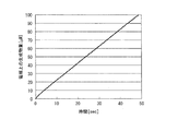
図14は、電気化学測定時に液の触れる領域の底面積に対し、作用極の面積の比が0.5のバイオセンサ(従来のもの)において、時間と作用極上の検出可能な範囲における生成物量との関係を示した結果である。また、図13は、電気化学測定時に液の触れる領域の底面積に対し、作用極の面積の比が0.7のバイオセンサ(本発明のもの)において、時間と作用極上の検出可能な範囲における生成物量との関係を示した結果である。図13も図14も反応初期である数10秒程度までの結果を示した。 FIG. 14 shows the time and the amount of product in a detectable range on the working electrode in a biosensor (conventional) having a working electrode area ratio of 0.5 to the bottom area of the area touched by the liquid during electrochemical measurement. It is the result which showed the relationship. FIG. 13 shows the time and the detectable range on the working electrode in a biosensor (invention) having a working electrode area ratio of 0.7 to the bottom area of the area touched by the liquid during electrochemical measurement. It is the result which showed the relationship with the product amount in. Both FIG. 13 and FIG. 14 show the results up to about several tens of seconds, which is the initial reaction.
ここで、線形性の程度を一次近似直線の相関関数Rの二乗値のR2値によって評価する。R2値が1に近づくほど、時間と生成物量との間の線形性の程度が大きくなるということになる。従来型のバイオセンサでは、図13のグラフの0〜10秒における近似直線のR2値は、0.9928であった。一方、本発明のバイオセンサでは、図14のグラフの0〜10秒における近似直線のR2値は、0.9990であった。したがって、面積比0.5の電気化学検出用バイオセンサでは、時間と生成物量との間の線形性の程度が小さく、ある時間における点と原点とを結ぶ直線の傾きから求めた初速度と、真の初速度とにずれがある。一方、面積比率0.7のバイオセンサでは、時間と生成物量との間の線形性の程度が大きく、より直線に近くなる。 Here, the degree of linearity is evaluated by the R 2 value of the square value of the correlation function R of the linear approximation line. The closer the R 2 value is to 1, the greater the degree of linearity between time and product quantity. In the conventional biosensor, the R 2 value of the approximate line at 0 to 10 seconds in the graph of FIG. 13 was 0.9928. On the other hand, in the biosensor of the present invention, the R 2 value of the approximate line at 0 to 10 seconds in the graph of FIG. 14 was 0.9990. Therefore, in the biosensor for electrochemical detection with an area ratio of 0.5, the degree of linearity between time and the amount of product is small, and the initial velocity obtained from the slope of the straight line connecting the point and the origin at a certain time, There is a deviation from the true initial speed. On the other hand, in the biosensor having an area ratio of 0.7, the degree of linearity between time and the amount of product is large, and is closer to a straight line.
さらに、図15は、反応初期(0〜10秒)の一次近似直線の相関係数Rの二乗値R2を、電気化学測定時に液の触れる領域の底面積に対する作用極の面積比ごとにプロットしたグラフである。図15より、作用極の面積比が大きくなるほど、R2値が1に近づいており、作用極の面積比が0.7以上1未満では、R2値が0.999以上、つまりほぼ1となる。逆に、面積比が0.7より小さくなるにつれR2値は急激に小さくなり、面積比0.1ではR2値は0.96まで悪くなる。したがって、作用極の面積比が0.7以上のバイオセンサは、短時間の反応時間で検出を行ったときに、その直線の傾きから求めた速度と、真の初速度との誤差が小さく、ほぼ等しい値となると言える。つまり、作用極の面積比を大きくすることによって短時間の反応時間でも、ターゲット物質の濃度をより正確に検出することが可能となる。 Further, FIG. 15 plots the square value R 2 of the correlation coefficient R of the first-order approximation line at the initial stage of reaction (0 to 10 seconds) for each area ratio of the working electrode to the bottom area of the area touched by the liquid during electrochemical measurement. It is a graph. From FIG. 15, the R 2 value approaches 1 as the working electrode area ratio increases, and when the working electrode area ratio is 0.7 or more and less than 1, the R 2 value is 0.999 or more, that is, approximately 1. Become. Conversely, as the area ratio becomes smaller than 0.7, the R 2 value decreases rapidly, and at an area ratio of 0.1, the R 2 value decreases to 0.96. Therefore, a biosensor having a working electrode area ratio of 0.7 or more has a small error between the speed obtained from the slope of the straight line and the true initial speed when detection is performed in a short reaction time. It can be said that the values are almost equal. That is, by increasing the area ratio of the working electrode, the concentration of the target substance can be detected more accurately even in a short reaction time.
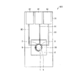
〔第1実施形態〕
図1は、本発明の一実施形態(第1実施形態)に係るバイオセンサ100の概略構成を示す上面図である。図1に示すように、バイオセンサ100は、作用極1、対極2、絶縁膜4、接続パットA1およびA2、リード電極部B1およびB2、反応部5、ならびに、基板20を備えている。
[First Embodiment]
FIG. 1 is a top view showing a schematic configuration of a
図1に示すように、バイオセンサ100では、基板20上の一方の端部に接続パットA1およびA2が形成され、反対側に、並列して作用極1および対極2が形成されている構造になっている。作用極1と接続パッドA1とを接続するようにリード電極部B1が形成され、対極2とA2とを接続するようにリード電極部B2が形成されている。さらに、リード電極部B1およびB2が試料液と接触しないように、リード電極部B1およびB2を覆うための絶縁膜4が形成された構造になっている。詳しい構造については下記にて記載する。
As shown in FIG. 1, the
作用極1は、試料液中にて生成した電気化学的活性物質である生成物を電気化学反応(酸化または還元)により検出する電極である。作用極1の材料としては、例えば、金属、カーボン、グラファイトなどの導電性材料が用いられる。
The working
対極2は、作用極1にて生じた電流を流すための電極である。対極2の材料としては、作用極1と同様の導電性材料を用いることができる。また、作用極1と異なる導電性材料を用いてもよい。
The
絶縁膜4は、リード電極部B1およびB2と、試料液が接触しないために形成されている絶縁性を有する膜である。絶縁膜4の材料としては、例えば、ポリイミドなどの絶縁性材料を用いることができる。
The insulating
接続パットA1およびA2は、電気化学検出用バイオセンサを電気化学測定装置(例えばポテンショスタット等)に接続するときに用いられ、作用極1と対極2と電気化学測定装置とを接続するために設けられている。接続パッドA1およびA2の材料としては、作用極1または対極2と同様の導電性材料を用いることができる。また、作用極1または対極2と異なる導電性材料を用いてもよい。
The connection pads A1 and A2 are used when connecting the electrochemical detection biosensor to an electrochemical measurement device (for example, a potentiostat), and are provided to connect the working
リード電極部B1およびB2は、作用極1と対極2とを、それぞれ接続パッドA1およびA2とつなぐために形成されている。リード電極部B1およびB2の大きさ(寸法)についても、任意の大きさを設定することができる。リード電極部B1およびB2の材料としては、作用極1および対極2と同様の材料を用いることができる。
The lead electrode portions B1 and B2 are formed to connect the working
基板20は、電子部品等を表面に固定し、何らかの機能を実現するための板状またはフィルム上の部品をいう。例えば、ガラス、石英、セラミックス、プラスチックなどの絶縁性材料が用いられる。
The
反応部5は、電気化学測定の際に、試料液を溜める(試料液が触れる)領域のことをいい、作用極1および対極2を含む電極系を含むように形成される。反応部5では、作用極1上に固定化された反応物質または結合物質とターゲット物質が直接または段階的に反応して、電気化学活性のある生成物を生成する反応が生じる。バイオセンサ100は、上記電極系(作用極1および対極2)を用いて、反応部5における上記反応を電気化学的に検出する。なお、反応物質および結合物質については後述する。
The
バイオセンサ100は、例えば、以下のように製造することができる。まず、基板20上にパターニングすることにより、作用極1、対極2、接続パットA1およびA2ならびにリード電極部B1およびB2をそれぞれ形成する。基板20の表面に作用極1を形成する方法としては、例えば、スパッタ法、蒸着法または印刷法等を用いることができる。対極2、接続パットA1およびA2、ならびに、リード電極部B1およびB2を形成させる場合についても、作用極1と同様の方法を用いることができる。また、バイオセンサ100を大量生産する場合には、バイオセンサ100が備える部材を複数パターニングした基板を分割してもよい。
The
つぎに、絶縁膜4を、リード電極部B1およびB2を完全に覆うようにして形成させる。これは、リード電極部B1およびB2と試料液とが接触してバイオセンサ100が誤動作することを防止することが目的である。これにより、試料液を反応部5にのみに接触させることができる。基板20の表面に、リード電極部B1およびB2を覆うようにして絶縁膜4を形成する方法は、例えば、フォトリソグラフィー、スクリーン印刷などの方法を用いることができる。
Next, the insulating
絶縁膜4の形成により、試料液が接触する反応部5が規定される。絶縁膜4の大きさは、絶縁膜4によって規定される反応部5の大きさ(底面積)と、作用極1との面積比率が0.7以上となるように、絶縁膜4の大きさを調整して生成する。これにより、反応部5の大きさを、反応部5に対する作用極1の面積比率が0.7以上となるように設定することができる。
The formation of the insulating
なお、本実施形態では、反応部5の外縁は絶縁膜4によって規定されているが、この方法に制限されるものではなく、後述するような様々な方法を用いて形成することができる。
In the present embodiment, the outer edge of the
対極2の大きさは、反応部5のうち、作用極が占める領域の残りの部分から、任意の大きさを選択できる。前述のように、対極2は作用極1から生じた電流を流すための電極であるので、対極2が作用極1に対して余りにも小さい場合、電流が流れにくくなり、正確な電気化学測定を行うことができなくなる。したがって、対極2は、作用極1から生じる電流を流すのに必要な大きさを選択することが望ましい。
The size of the
接続パッドA1およびA2それぞれの位置は、電気化学測定装置との接続位置に応じて適宜設定可能であり、接続可能な位置であれば特に限定されない。また、接続パッドA1およびA2の大きさは、電気化学測定装置側の接続パッドと充分に接触する大きさであればよい。 The position of each of the connection pads A1 and A2 can be appropriately set according to the connection position with the electrochemical measurement device, and is not particularly limited as long as it can be connected. The size of the connection pads A1 and A2 only needs to be large enough to be in contact with the connection pad on the electrochemical measuring device side.
作用極1上に、ターゲット物質と反応し生成物を生成する反応物質またはターゲット物質と結合する結合物質を固定化させる。
A reactive substance that reacts with the target substance to produce a product or a binding substance that binds to the target substance is immobilized on the working
反応物質は、ターゲット物質と直接反応して生成物を生成する。結合物質は、ターゲット物質と反応後、さらなる反応によって生成物を生成する。 The reactant reacts directly with the target material to produce a product. The binding material generates a product by further reaction after reacting with the target material.
反応物質あるいは結合物質は、検出したいターゲット物質によって酵素、抗体、ペプチド、DNA、オリゴヌクレオチド、レクチン、レセプター、糖など任意の生体材料を選択する。例えば、試料液中の糖を検出する場合には、グルコースオキシダーゼなどの酵素が選択される。 As a reactive substance or a binding substance, an arbitrary biological material such as an enzyme, an antibody, a peptide, DNA, an oligonucleotide, a lectin, a receptor, or a sugar is selected depending on a target substance to be detected. For example, when detecting sugar in the sample solution, an enzyme such as glucose oxidase is selected.
試料液中のターゲット物質がイムノアッセイにより検出される場合は、ターゲットの物質を特異的に結合する抗体もしくはペプチドなどが選択される。反応物質あるいは結合物質は、作用極1の全面に固定化されていることが好ましい。
When the target substance in the sample solution is detected by immunoassay, an antibody or peptide that specifically binds to the target substance is selected. It is preferable that the reactive substance or the binding substance is immobilized on the entire surface of the working
上記固定化に関しては、作用極1の全面に隙間無く行う必要はなく、離散的に固定化されていてもよい。ただし、その固定化された面積は反応部の面積に対して0.7以上であることが好ましい。
The immobilization need not be performed on the entire surface of the working
反応物質あるいは結合物質を作用極1に固定化する方法としては、例えば、物理吸着、作用極1の表面に形成した官能基と反応物質との共有結合、または3次元網目構造を有する高分子材料によるタンパク質の取り込み(包括)等を利用した、公知の方法を採用することができる。離散的に固定化する場合、スポッターなどを用いてもよい。
Examples of the method for immobilizing the reactive substance or the binding substance on the working
なお、本実施形態に係るバイオセンサ100は、基板20上に、作用極1および対極2が集約して形成されているので、検出に必要な試料液の量を少なくすることができるという利点も有している。
Note that the
なお、作用極1、対極2、絶縁膜4、接続パットA1およびA2、リード電極部B1およびB2、反応部5ならびに基板20の形状は図1に示されたものである必要はなく、特に限定されるものではなく、矩形、円形、楕円形またはその他任意の形状とすることができる。
The shapes of the working
〔バイオセンサを用いた分析方法〕
この分析方法は、ターゲット物質を含む試料溶液を、上記反応部5に導入する導入工程と、上記反応物質と上記ターゲット物質との反応によって生成された電気化学活性物質を測定する測定工程からなる。
[Analysis method using a biosensor]
This analysis method includes an introduction step of introducing a sample solution containing a target material into the
上記バイオセンサ100の構成により、ターゲット物質を含む試料液を反応部5に導入すれば、作用極1上に固定した反応物質と反応し生成物を生成、または作用極1上に固定した結合物質と結合する。上記反応または結合をさせた後、電気化学測定を行うことにより、検出された電流値から試料液中のターゲット物質の濃度を求めることができる。
When the sample liquid containing the target substance is introduced into the
まず、電気化学検出用バイオセンサの接続パッドA1、A2およびA3を、電気化学測定装置(例えばポテンショスタット)に接続する。接続パッドA1、A2およびA3の接続方法としては、例えば両端にワニ口クリップが設けられたコードを用意し、一方のクリップにより接続パッドA1、A2およびA3を挟み、他方のクリップによりポテンショスタットの端子を挟む方法が挙げられるが、この方法に制限されるものではない。 First, the connection pads A1, A2 and A3 of the electrochemical detection biosensor are connected to an electrochemical measurement device (for example, a potentiostat). As a method of connecting the connection pads A1, A2 and A3, for example, a cord having an alligator clip provided at both ends is prepared, the connection pads A1, A2 and A3 are sandwiched by one clip, and the potentiostat terminal by the other clip However, the method is not limited to this method.
以下、バイオセンサ100を用いた分析方法の一例として、試料液中の糖(グルコース)を測定する方法について説明するが、本実施形態はこれに限定されず、その他のターゲット物質の測定にも適用可能である。
Hereinafter, as an example of an analysis method using the
試料液中の糖を測定する場合、バイオセンサ100の作用極1には、反応物質として、酵素(グルコースオキシダーゼ)を固定化する。前記反応物質を作用極1に固定化する方法としては、上述のように、物理吸着、作用極1の表面に形成した官能基と反応物質との共有結合、または3次元網目構造を有する高分子材料によるタンパク質の取り込み(包括)等を利用した、公知の方法を採用することができる。また、作用極1における反応物質の固定化箇所は、特に限定されないが、作用極1の全面に固定ることが好ましい。
When measuring sugar in the sample solution, an enzyme (glucose oxidase) is immobilized on the working
次に、グルコースを含む試料液を反応部5に導入する。具体的には、バイオセンサ100の反応部5に試料液を滴下する。グルコースと作用極1に固定化された酵素とが反応して、生成物(過酸化水素)が生成する。作用極1と対極2との間にに電圧を印加することにより、グルコース量に応じた電流が得られ、その結果から試料液中のグルコースの濃度を測定することができる。
Next, a sample solution containing glucose is introduced into the
試料液には、電子移動を仲介するためのメディエーターを加えてもよい。メディエーターとしては、フェロシアン化カリウム/フェリシアン化カリウム、ベンゾキノン/ハイドロキノン、フェリシニウム/フェロセンなどの系を用いることができる。グルコースを測定する系の場合、酵素とグルコースとが反応し、メディエーターを介在した電子の移動にともなって生ずる電流をシグナルとして測定する。そうすることで、検出された電流値から試料液中のターゲット物質の濃度を求めることができる。 A mediator for mediating electron transfer may be added to the sample solution. As the mediator, systems such as potassium ferrocyanide / potassium ferricyanide, benzoquinone / hydroquinone, ferricinium / ferrocene can be used. In the case of a system for measuring glucose, the enzyme reacts with glucose, and the current generated as a result of the movement of electrons through the mediator is measured as a signal. By doing so, the concentration of the target substance in the sample liquid can be obtained from the detected current value.
次に、バイオセンサ100を用いた分析方法の他の例として、試料液中の微量物質をイムノアッセイにて測定する方法について説明する。
Next, as another example of an analysis method using the
試料液中の微量物質をイムノアッセイにて測定する場合、バイオセンサ100の作用極1には、結合物質としてターゲット物質を特異的に捕捉することのできる抗体またはペプチドを固定する(以下、抗体を固定した場合について説明するが、ペプチドを固定した場合も分析方法は同様である)。固定する方法としては、酵素を固定する場合と同様の方法を採用することができる。また、結合物質は、作用極1の全面に固定することが好ましい。また、試料液を滴下する前に、作用極1の表面をアルブミン水溶液により処理して、非特異吸着防止膜を形成した後、バッファー液を用いて洗浄しておいてもよい。これにより、作用極1の表面へのターゲット物質の非特異的な吸着を防ぐことができる。
When measuring a trace substance in a sample solution by immunoassay, an antibody or peptide capable of specifically capturing a target substance as a binding substance is immobilized on the working
ターゲット物質を含む試料液を反応部5に滴下することによって、抗原抗体反応が進行する。続いて、反応部5を、バッファー液を用いて洗浄した後、第二の結合物質である酵素標識抗体を含む液を滴下して反応させる。ここで、作用極1の表面には、抗体−ターゲット物質−酵素標識抗体のサンドイッチ複合体が形成される。続いて、反応部5を、バッファー液を用いて洗浄する。次いで、酵素に対する基質を含む試料液を反応部5に滴下する。作用極1の表面に形成されたサンドイッチ複合体の中において、酵素基質反応が進行し、電気化学活性のある生成物が生成する。作用極1に電圧を印加することによって、ターゲット物質量に応じた電流が得られる。その結果から試料液中のターゲット物質の濃度を求めることができる。
By dropping a sample solution containing the target substance onto the
また、基質を含む試料液には、上述と同様に、電子移動を仲介するためのメディエーターを加えてもよい。 In addition, a mediator for mediating electron transfer may be added to the sample solution containing the substrate in the same manner as described above.
〔第2実施形態〕
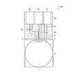
図2は、本発明の一実施形態(第2実施形態)に係るバイオセンサ200の概略構成を示す上面図である。
[Second Embodiment]
FIG. 2 is a top view showing a schematic configuration of a
なお、説明の便宜上、前記第1実施形態にて説明した図面と同じ機能を有する部材については、同じ符号を付記し、その説明を省略する。またバイオセンサを用いた分析方法に関しても上述した方法と同様のため、その説明も省略する。 For convenience of explanation, members having the same functions as those in the drawings described in the first embodiment are given the same reference numerals, and descriptions thereof are omitted. Also, the analysis method using a biosensor is the same as the method described above, and therefore the description thereof is omitted.
図2に示すように、バイオセンサ200は、作用極1、対極2、参照極3、絶縁膜4、接続パットA1、A2およびA3、リード電極部B1、B2およびB3、反応部5ならびに基板20を備えている。
As shown in FIG. 2, the
基板20における一方の端部に、接続パッドA1、A2およびA3が形成されている。また、作用極1、対極2および参照極3が、基板20上の、接続パッドA1、A2およびA3が形成されている側とは反対側に形成されている。また、作用極1と接続パッドA1とを、対極2と接続パッドA2とをおよび参照極3と接続パッドA3とを接続するように、リード電極部B1、B2およびB3がそれぞれ形成されている。さらに、リード電極部B1、B2およびB3が試料液と接触しないように、リード電極部を覆うように絶縁膜4が形成されている。それゆえに試料液は図2に示す反応部5にのみ接触するようになっている。
Connection pads A1, A2 and A3 are formed at one end of the
上記構造を有し、作用極1を反応部5に対して面積比率0.7以上で形成するという条件を満たしていれば、各部材の大きさおよび形状は限定されない。第2実施形態は、参照極3を含むという点が、第1実施形態とは異なる。
If it has the said structure and the conditions of forming the working
参照極3は、作用極1に所望の安定した電位を印加するための電極である。図2に示されるバイオセンサ200では、参照極3は、作用極1の中に埋め込まれるようにして形成されている。参照極3の位置はこの位置に制限されるものではないが、参照極3は、溶液抵抗によりIRドロップが生じることを考慮すると、できる限り作用極1の近傍に配置されていることが望ましい。また参照極3の大きさ(寸法)は、特に限定されないが、作用極1を反応部5に対して面積比率0.7以上で形成するため、参照極3は小さいことが好ましい。
The
参照極3の材料は、導電性材料であり、かつ、電流が流れた際にも電位が安定している材料が望ましい。例えば、銀塩化銀電極はよく用いられる参照極の一つである。
The material of the
基板20の表面に参照極3を形成する方法としては、例えば、スパッタ法、蒸着法、印刷法等を用いることができる。
As a method for forming the
参照極3によって、作用極1に安定した電位を印加することができるので、より正確な検出が可能となるという特徴を有する。
Since a stable potential can be applied to the working
また、作用極1の中心が、反応部5の底面の中央部にあることが望ましい。
Moreover, it is desirable that the center of the working
上記の構成により、反応部5のうち、電気化学測定に関与する拡散層の濃度勾配が作用極5を中心としておおよそ均等となるため、電気化学反応が均一に起こり、より短時間の反応時間での検出が可能となるからである。なお中央部は、反応部の中心を基準に反応部全体に対して三分の一程度の領域を指すものとし、作用極の中心が反応部の底面の中央部にあればいいので、図2の形状には限定されない。
With the above configuration, the concentration gradient of the diffusion layer involved in the electrochemical measurement in the
さらに、作用極1の底面の形状が、反応部5の底面の形状と相似形であることが望ましい。
Furthermore, it is desirable that the shape of the bottom surface of the working
上記の構成により、反応部5のうち、電気化学測定に関与する拡散層の濃度勾配が作用極を中心として均等となるため、電気化学反応が均一に起こり、より短時間の反応時間での検出が可能となるからである。作用極の底面の形状が、反応部の底面の形状と相似形であればいいので、図2の形状には限定されない。
With the above configuration, the concentration gradient of the diffusion layer involved in the electrochemical measurement in the
〔第3実施形態〕
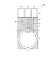
図3は、本発明の一実施形態(第3実施形態)に係るバイオセンサ300の概略構成を示す上面図である。
[Third Embodiment]
FIG. 3 is a top view showing a schematic configuration of a
図3に示されるバイオセンサ300は、絶縁膜4の代替として、接続パッドA1、A2およびA3ならびに反応部5以外の部分を、疎水性膜(疎水性部分)6を用いて被覆させている点で図2のバイオセンサ200と異なる。したがって、反応部5は、疎水性膜6によって規定される。それ以外の点においては、第2実施形態と同様である。
The
疎水性膜6は、反応部5を規定し、それ以外の領域に試料液の液滴を広がらせないためのものである。バイオセンサ300では、反応部5以外の部分を覆うように形成されている。
The
疎水性膜6の材料は、その表面が疎水性を有し、かつ、絶縁性の材料が望ましい。疎水性膜6の形成方法は、例えば、疎水性ポリマーをコートしたり、オクタドデシルトリクロロシランのトルエン溶液によって化学修飾したりするなどの方法を採用することができる。
The material of the
疎水性膜6によって、反応部5が首尾よく規定されるので、最小限の液量により測定することが可能であるという効果を有する。
Since the
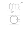
〔第4実施形態〕
図4は、本発明の一実施形態(第4実施形態)に係るバイオセンサ400の概略構成を示す上面図である。
[Fourth Embodiment]
FIG. 4 is a top view showing a schematic configuration of a
図4に示される電気化学検出用バイオセンサは、作用極1が複数個から成り、それぞれの作用極1において、接続パットA1と接続させるためにリード電極部B1が形成されている以外は、第3実施形態と同様である。
The biosensor for electrochemical detection shown in FIG. 4 includes a plurality of working
複数の作用極の総面積は、反応部5の底面積の0.7以上を占めるように形成されている。
The total area of the plurality of working electrodes is formed to occupy 0.7 or more of the bottom area of the
作用極が複数になることより、個々の作用極の面積が小さくなるが、微小電極の効果により電流値が増幅され、高感度の検出が可能であるという効果を有する。 By having a plurality of working electrodes, the area of each working electrode is reduced, but the current value is amplified by the effect of the microelectrodes, and this has the effect that highly sensitive detection is possible.
〔第5実施形態〕
図5は、本発明の一実施形態(第5実施形態)に係るバイオセンサ500の概略構成を示す上面図である。
[Fifth Embodiment]
FIG. 5 is a top view showing a schematic configuration of a
図5に示されるバイオセンサ500は、作用極1の大きさが反応部5の大きさよりも大きいこと以外は、第3実施形態と同様である。疎水性膜6によって、反応部5内の作用極の有効面積が規定される。バイオセンサ500では、作用極の有効面積が、反応部5の0.7以上となっている。
The
図5に示されたバイオセンサ500のように、作用極1の全部分が反応部5からはみ出して形成されていてもよいし、図6に示されたバイオセンサ500´ように、作用極1の一部分が反応部5からはみ出して形成されてもよい。
Like the
〔第6実施形態〕
図7は、本発明の一実施形態(第6実施形態)に係るバイオセンサ600の概略構成を示す上面図である。図8は第6実施形態のバイオセンサ600の概略構造を示す斜視図である。図8においては、作用極1等の詳細な構造は省略してある。
[Sixth Embodiment]
FIG. 7 is a top view showing a schematic configuration of a
バイオセンサ600は、反応部5がその周囲を囲む壁面7によって規定されている点および疎水性膜6によって被覆されていない点以外は、第5実施形態と同様である。
The
壁面7は、反応部6を規定し、それ以外の領域に試料液の液滴を広がらせないためのものである。バイオセンサ600では、壁面7は、平面視において円形の反応部6を取り囲むように円周状に形成されている。しかしながら、この形状に制限されるものではなく、反応部6の形状に応じて任意に形成することができる。また壁面7は、液が広がっていかない高さがあればよい。壁面7の材料は、ガラス、石英、セラミックス、プラスチックなどを用いることができる。ポリジメチルシロキサン(PDMS)を材料として用いることによって、加工および量産が容易となる。
The
壁面7を形成する方法は、例えば、機械的に加工する方法、エッチングなどの化学処理により形成する方法などが挙げられ、特に限定されない。また各部パターンを形成した型に光硬化性樹脂または熱硬化性樹脂を流し込んで固めて作成する方法もある。またポリオレフィン系樹脂、ポリメタクリル酸系樹脂、またはポリカーボネイト樹脂からなる材料を、各部パターンを形成した型を用いて、ホットエンボス法により形成してもよい。
The method for forming the
作成した壁面7を基板20と貼り合わせることによって、反応部6が規定される。
The
壁面7を導入することにより、反応部5以外に試料液が広がることを確実に抑制することができる。
By introducing the
〔第7実施形態〕
図9は、本発明の一実施形態(第7実施形態)に係るバイオセンサ700の概略構成を示す上面図およびX−Y断面図である。図10は第7実施形態のバイオセンサの概略構造を示す斜視図である。図10においては、作用極1等の詳細構造は省略してある。
[Seventh Embodiment]
FIG. 9 is a top view and an XY sectional view showing a schematic configuration of a
反応チャンバ8は、反応部5を囲む壁面および天井部分からなっており、反応部5を空間として規定している。さらに反応チャンバ8には、液を入れるための導入部9および液を排出するための排出部10が形成されている。
The
バイオセンサ700は、基板20上に導入部9および排出部10を有する反応チャンバ8が形成されている点ならびに絶縁膜4が被覆されていない点以外は、実施の形態2と同様である。
反応チャンバ8は、円柱状の空間として形成されているが、この形状に制限されるものではなく、反応部6の形状に応じて任意に形成することが可能である。反応チャンバ8の材料は、ガラス、石英、セラミックス、プラスチックなどを用いることができる。ポリジメチルシロキサン(PDMS)を材料として用いることよって、加工および量産が容易となる。
The
反応チャンバ8を形成する方法は、上記壁面7を形成する方法と同様のものを用いてもよく、特に限定されない。
The method for forming the
反応チャンバ8により、空間として反応部5を規定することによって、反応部5以外へ試薬液が広がることを確実に抑制することができる。
By defining the
反応チャンバ8は、反応部5を空間として規定するためのものである。
The
導入部9は、反応部5へ試料液などを導入するためのものである。
The
排出部10は、反応部5に導入された試料液を排出するためのものである。また、導入時には、空気穴としての役割も果たすことができる。
The
バイオセンサ700では、導入部9および排出部10は、反応部5から接続して開口した円形の穴として形成されているが、液を導入できる形状であれば他の形状でもよい。
In the
また液の排出は、導入部9から行ってもよく、この場合は、排出部10は空気穴として使用する。
In addition, the liquid may be discharged from the
以下、第7実施形態に示された電気化学検出用バイオセンサを用いた分析方法について説明する。この分析方法は、実施の形態1〜6に示された電気化学検出用バイオセンサを用いた分析方法とは、試料液またはバッファー液等を反応部5へ滴下していた部分が、導入部9から液を導入し、排出部10から排出するという点で異なるが、後は同様である。
Hereinafter, an analysis method using the electrochemical detection biosensor shown in the seventh embodiment will be described. This analysis method is different from the analysis method using the biosensor for electrochemical detection shown in
本発明は上述した各実施形態に限定されるものではなく、請求項に示した範囲において種々の変更が可能であり、異なる実施形態にそれぞれ開示された技術的手段を適宜組み合わせて得られる実施形態についても本発明の技術的範囲に含まれる。 The present invention is not limited to the above-described embodiments, and various modifications can be made within the scope shown in the claims, and the embodiments can be obtained by appropriately combining technical means disclosed in different embodiments. Is also included in the technical scope of the present invention.
〔実施例1〕
図11は実施例1に係るバイオセンサ800の概略構成を示す上面図である。図11を用いて実施例1を説明する。
[Example 1]
FIG. 11 is a top view illustrating a schematic configuration of the
まず、10cm×10cm×厚さ0.5mmのガラスウェハ(コーニング社製 EagleXG)に作用極1、対極2、接続パッドA1、A2およびA3、リード電極部B1、B2およびB3を、フォトリソグラフィを用いて形成した。これらは全て金をスパッタすることによって形成した。作用極1は、直径2mmの円形とし、対極2は作用極1を囲むような円弧状の形状に形成した。
First, a working
次に、同様にフォトリソグラフィを用いて、銀電極を形成した。そして極の一部を化学的に塩化銀に変化させ、銀および塩化銀からなる参照極3を形成した。
Next, similarly, photolithography was used to form a silver electrode. A part of the pole was chemically changed to silver chloride to form a
ガラスウェハには図11に示す電極基板(1cm×2cm)を複数枚形成し、ガラスカッターを用いて1枚1枚切断した。 A plurality of electrode substrates (1 cm × 2 cm) shown in FIG. 11 were formed on a glass wafer, and each piece was cut using a glass cutter.
続いて、反応チャンバを作製するための型を作製した。シリコンウェハに、底面の形状が直径2.3mmの円形であって、高さ40umの型を作製した。ここにポリジメチルシロキサン(PDMS)を流しこみ、焼き固めて反応チャンバを作製した。反応チャンバの両端に直径0.5mmの穴をあけて、導入部9および排出部10とした。
Subsequently, a mold for producing a reaction chamber was produced. On the silicon wafer, a mold having a bottom shape of a circle having a diameter of 2.3 mm and a height of 40 μm was produced. Polydimethylsiloxane (PDMS) was poured into this and baked and hardened to prepare a reaction chamber. Holes with a diameter of 0.5 mm were made at both ends of the reaction chamber to form an
電極基板の作用極上に形成したチオール分子による自己組織化単分子膜(SAM)を介して、グルコースオキシダーゼを固定化した。 Glucose oxidase was immobilized via a self-assembled monolayer (SAM) formed of thiol molecules formed on the working electrode of the electrode substrate.
反応チャンバを、グルコースオキシダーゼを固定化した基板に貼り合わせ、実施例1のバイオセンサ800とした。
The reaction chamber was bonded to a substrate on which glucose oxidase was immobilized to obtain
この実施例1における反応チャンバによって形成される反応部の底面積と、作用極との面積比率は、0.76となった。 The area ratio between the bottom area of the reaction part formed by the reaction chamber in Example 1 and the working electrode was 0.76.
〔比較例1〕
反応チャンバを作製するための型において、底面の形状が直径2.8mmの円形であって、高さ40umの型を作製した。ここにPDMSを流し込み、焼き固めて反応チャンバを作製した。
[Comparative Example 1]
In the mold for producing the reaction chamber, a mold having a bottom surface of 2.8 mm in diameter and a height of 40 μm was produced. PDMS was poured into this and baked and hardened to prepare a reaction chamber.
グルコースオキシダーゼを固定化した基板に、反応チャンバを貼り合わせ、比較例1のバイオセンサとした。 A reaction chamber was bonded to a substrate on which glucose oxidase was immobilized to obtain a biosensor of Comparative Example 1.
この比較例1における、反応チャンバによって形成される反応部の底面積と、作用極との面積比率は、0.51となった。 In Comparative Example 1, the area ratio between the bottom area of the reaction portion formed by the reaction chamber and the working electrode was 0.51.
(グルコースの検出)
実施例1および比較例1のバイオセンサを用いて、グルコースの検出を行った。グルコース溶液は、50mg/dL、100mg/dL、250mg/dLのものを調製した。
(Detection of glucose)
Using the biosensors of Example 1 and Comparative Example 1, glucose was detected. Glucose solutions were prepared with 50 mg / dL, 100 mg / dL, and 250 mg / dL.
反応部にグルコース溶液を入れ、10秒後の電流値を測定した。バックグラウンド電流を補正後、時間に対して電流値をプロットし、原点との2点を結ぶ直線の傾きから初速度を求めた。 The glucose solution was put into the reaction part, and the current value after 10 seconds was measured. After correcting the background current, the current value was plotted against time, and the initial velocity was obtained from the slope of a straight line connecting two points with the origin.
面積比率0.51の比較例1の場合、グルコース濃度と初速度とは比例しなかったが、面積比率0.76の実施例1の場合、グルコース濃度は初速度に比例した。直線の傾きから求めた初速度が、真の初速度とほぼ等しく求めることができた。 In Comparative Example 1 with an area ratio of 0.51, the glucose concentration and the initial rate were not proportional, but in Example 1 with an area ratio of 0.76, the glucose concentration was proportional to the initial rate. The initial speed obtained from the slope of the straight line was found to be almost equal to the true initial speed.
以上のことから、本発明に係るバイオセンサによれば、短時間の反応時間でも、未知濃度のグルコース測定の初速度を正確に求めることができ、ある既知濃度のグルコース測定の初速度と比較することによって、グルコースの濃度を求めることができる。 From the above, according to the biosensor according to the present invention, the initial rate of glucose measurement at an unknown concentration can be accurately determined even in a short reaction time, and compared with the initial rate of glucose measurement at a certain known concentration. Thus, the glucose concentration can be determined.
〔実施例2〕
実施例1と同様に作製した電極基板の作用極上に、チオール分子による自己組織化単分子膜(SAM)を介して、抗CRP抗体を固定化した。実施例1と同様の反応チャンバを貼り合わせて、実施例2のバイオセンサとした。
[Example 2]
An anti-CRP antibody was immobilized on the working electrode of the electrode substrate produced in the same manner as in Example 1 via a self-assembled monolayer (SAM) with thiol molecules. A reaction chamber similar to that in Example 1 was bonded to obtain the biosensor of Example 2.
〔比較例2〕
実施例1と同様に作製した電極基板の作用極上に、実施例2と同様に抗CRP抗体を固定化した。比較例1と同様の反応チャンバを貼り合わせて、比較例2のバイオセンサとした。
[Comparative Example 2]
An anti-CRP antibody was immobilized on the working electrode of the electrode substrate produced in the same manner as in Example 1, as in Example 2. A reaction chamber similar to that of Comparative Example 1 was bonded to obtain a biosensor of Comparative Example 2.
(CRPの検出)
実施例2および比較例2のバイオセンサを用いて、CRPの検出を行った。まず、実施例2および比較例2のバイオセンサの反応部に、カゼイン溶液を入れ、30分室温にて静置し、非特異吸着防止膜を形成した。カゼイン溶液を排出し、PBS溶液を用いて反応部内を洗浄した。次に、反応部にCRP溶液を入れ、3分室温にて静置し、作用極上に固定化された抗体とCRPとの複合体を形成した。CRP溶液は、0.2mg/dL、2mg/dL、10mg/dLのものを使用した。CRP溶液を排出し、反応部内を洗浄した。次に、反応部に第二の結合物質として、ALP標識抗CRP抗体溶液を入れ、3分室温にて静置し、固定化抗体−CRP−ALP標識抗体のサンドイッチ複合体を形成した。ALPとは、アルカリフォスファターゼという酵素のことである。ALP標識抗体を排出し、反応部内を洗浄した。反応部に、p−アミノフェニルリン酸塩(pAPP)溶液を入れ、10秒後の電流値を測定した。バックグラウンド電流を補正後、時間に対して電流値をプロットし、原点との2点を結ぶ直線の傾きから初速度を求めた。
(Detection of CRP)
CRP was detected using the biosensors of Example 2 and Comparative Example 2. First, the casein solution was put into the reaction part of the biosensors of Example 2 and Comparative Example 2 and allowed to stand at room temperature for 30 minutes to form a nonspecific adsorption preventing film. The casein solution was discharged, and the reaction part was washed with a PBS solution. Next, the CRP solution was added to the reaction part, and allowed to stand at room temperature for 3 minutes to form a complex of the antibody and CRP immobilized on the working electrode. The CRP solution used was 0.2 mg / dL, 2 mg / dL, 10 mg / dL. The CRP solution was discharged and the inside of the reaction part was washed. Next, an ALP-labeled anti-CRP antibody solution was added as a second binding substance to the reaction part and allowed to stand at room temperature for 3 minutes to form an immobilized antibody-CRP-ALP-labeled antibody sandwich complex. ALP is an enzyme called alkaline phosphatase. The ALP-labeled antibody was discharged and the inside of the reaction part was washed. A p-aminophenyl phosphate (pAPP) solution was put into the reaction part, and the current value after 10 seconds was measured. After correcting the background current, the current value was plotted against time, and the initial velocity was obtained from the slope of a straight line connecting two points with the origin.
面積比率0.51の比較例2の場合、CRP濃度と初速度とは比例しなかったが、面積比率0.76の実施例2の場合、CRP濃度は初速度に比例した。直線の傾きより求めた初速度を、真の初速度とほぼ等しく求めることができた。 In Comparative Example 2 having an area ratio of 0.51, the CRP concentration was not proportional to the initial speed, but in Example 2 having an area ratio of 0.76, the CRP concentration was proportional to the initial speed. The initial velocity obtained from the slope of the straight line was found to be almost equal to the true initial velocity.
以上のことから、本発明を用いると、短時間の反応時間によって、未知濃度のCRP測定の初速度を正確に求めることができ、ある既知濃度のCRP測定の初速度と比較することにより、グルコースの濃度を求めることができる。 From the above, by using the present invention, the initial rate of CRP measurement at an unknown concentration can be accurately determined with a short reaction time, and by comparing with the initial rate of CRP measurement at a certain known concentration, glucose Can be determined.
なお、CRPに限ったものではなく、本発明はイムノアッセイ一般に用いることも可能である。 The present invention is not limited to CRP, and the present invention can also be used in general immunoassays.
本発明にかかるバイオセンサは、電気化学測定を行うことにより、検出された電流値から試料液中のターゲット物質の濃度を求めることができるため、生体、環境、医療、食品などに関する試料の分析に利用することができる。 Since the biosensor according to the present invention can determine the concentration of the target substance in the sample liquid from the detected current value by performing electrochemical measurement, it can be used for analysis of samples related to living organisms, environment, medicine, food, etc. Can be used.
1 作用極
2 対極
3 参照極
A1〜A3 接続パッド
B1〜B3 リード電極部
4 絶縁膜
5 反応部
6 疎水性膜
7 壁面
8 反応チャンバ
9 導入部
10 排出部
20 基板
DESCRIPTION OF
Claims (13)
対極と、
該ターゲット物質を含む試料液を溜める反応部と、を備えており、
該作用極および該対極は、該反応部の底面に配置されており、
該反応部の底面において該作用極が占める割合が0.7以上であることを特徴とするバイオセンサ。 A reactive substance that reacts with the target substance to produce a product, or a working electrode to which a binding substance that binds to the target substance is fixed;
With the counter electrode,
A reaction part for storing a sample solution containing the target substance,
The working electrode and the counter electrode are disposed on the bottom surface of the reaction part,
The biosensor characterized in that the working electrode occupies 0.7 or more of the bottom surface of the reaction part.
該疎水性部分が上記反応部を囲むように配置されていることを特徴とする請求項1から3の何れか1項に記載のバイオセンサ。 It has a hydrophobic part with hydrophobicity,
The biosensor according to any one of claims 1 to 3, wherein the hydrophobic part is arranged so as to surround the reaction part.
該反応チャンバは、該反応チャンバ内に上記試料液を注入するための注入口と、上記反応チャンバ内の上記試料液を排出するための排出口とを備えていることを特徴とする請求項1から3の何れか1項に記載のバイオセンサ。 A reaction chamber for storing the reaction section;
2. The reaction chamber includes an inlet for injecting the sample liquid into the reaction chamber and an outlet for discharging the sample liquid in the reaction chamber. 4. The biosensor according to any one of items 1 to 3.
ターゲット物質を含む試料液を、上記反応部に導入する導入工程、および
上記作用極と上記対極との間に電圧を印加することで、反応または結合した上記ターゲット物質に応じた電流値を測定する工程、を含むことを特徴とする分析方法。 An analysis method using the biosensor according to any one of claims 1 to 12,
Introducing the sample solution containing the target substance into the reaction part, and applying a voltage between the working electrode and the counter electrode to measure a current value corresponding to the target substance reacted or combined A process comprising the steps of:
Priority Applications (2)
| Application Number | Priority Date | Filing Date | Title |
|---|---|---|---|
| JP2011116211A JP2012242366A (en) | 2011-05-24 | 2011-05-24 | Biosensor and analytic method using the same |
| US13/419,456 US20120298528A1 (en) | 2011-05-24 | 2012-03-14 | Biosensor and analysis method using same |
Applications Claiming Priority (1)
| Application Number | Priority Date | Filing Date | Title |
|---|---|---|---|
| JP2011116211A JP2012242366A (en) | 2011-05-24 | 2011-05-24 | Biosensor and analytic method using the same |
Publications (1)
| Publication Number | Publication Date |
|---|---|
| JP2012242366A true JP2012242366A (en) | 2012-12-10 |
Family
ID=47218493
Family Applications (1)
| Application Number | Title | Priority Date | Filing Date |
|---|---|---|---|
| JP2011116211A Pending JP2012242366A (en) | 2011-05-24 | 2011-05-24 | Biosensor and analytic method using the same |
Country Status (2)
| Country | Link |
|---|---|
| US (1) | US20120298528A1 (en) |
| JP (1) | JP2012242366A (en) |
Cited By (2)
| Publication number | Priority date | Publication date | Assignee | Title |
|---|---|---|---|---|
| WO2021009942A1 (en) * | 2019-07-18 | 2021-01-21 | 株式会社ファーストスクリーニング | Electrochemical sensor unit |
| JP2021018227A (en) * | 2019-12-23 | 2021-02-15 | 株式会社ファーストスクリーニング | Electrochemical sensor unit |
Families Citing this family (4)
| Publication number | Priority date | Publication date | Assignee | Title |
|---|---|---|---|---|
| CN103412012B (en) | 2013-03-28 | 2015-09-09 | 利多(香港)有限公司 | Biology sensor |
| CN103454321B (en) * | 2013-03-28 | 2015-09-09 | 利多(香港)有限公司 | Biology sensor and manufacture method thereof |
| EP4031869A1 (en) * | 2019-09-20 | 2022-07-27 | Momm Diagnostics GmbH | Immunoassay analyzer, immunoassay kit and method for detecting analyte in liquid sample |
| IT202100021668A1 (en) * | 2021-08-10 | 2023-02-10 | Fondazione St Italiano Tecnologia | ELECTROCHEMICAL BIOSENSOR AND METHOD FOR THE DETECTION OF ENVIRONMENTAL CONTAMINANTS |
Citations (4)
| Publication number | Priority date | Publication date | Assignee | Title |
|---|---|---|---|---|
| JP2001215208A (en) * | 2000-02-01 | 2001-08-10 | Nec Corp | Chemical, sensor cartridge, chemical sensor provided with same, and method of measuring sample using it |
| JP2005114687A (en) * | 2003-10-10 | 2005-04-28 | Seiko Epson Corp | Electrochemical sensor and manufacturing method therefor |
| JP2007278981A (en) * | 2006-04-11 | 2007-10-25 | Japan Advanced Institute Of Science & Technology Hokuriku | Planar electrode and electrochemical detection sensor using the same |
| JP2009139114A (en) * | 2007-12-04 | 2009-06-25 | Toyobo Co Ltd | Electrochemical sensor for immunoassay |
Family Cites Families (8)
| Publication number | Priority date | Publication date | Assignee | Title |
|---|---|---|---|---|
| US4511659A (en) * | 1983-03-04 | 1985-04-16 | Esa, Inc. | Liquid chromatograph with electrochemical detector and method |
| US6511854B1 (en) * | 1997-07-31 | 2003-01-28 | The Uab Research Foundation | Regenerable biosensor using total internal reflection fluorescence with electrochemical control |
| WO2001038873A2 (en) * | 1999-11-24 | 2001-05-31 | Biotronic Technologies, Inc. | Devices and methods for detecting analytes using electrosensor having capture reagent |
| EP1321763B1 (en) * | 2000-09-25 | 2010-01-27 | Asahi Kasei Kabushiki Kaisha | Enzyme electrode |
| US6863800B2 (en) * | 2002-02-01 | 2005-03-08 | Abbott Laboratories | Electrochemical biosensor strip for analysis of liquid samples |
| US7727367B2 (en) * | 2002-08-13 | 2010-06-01 | Gunze Limited | Biosensor and method for manufacturing same |
| WO2005022155A1 (en) * | 2003-08-29 | 2005-03-10 | Kabushiki Kaisha Toshiba | Color reagent, concentration measuring kit, method of concentration measuring and sensor chip for use therein |
| WO2008044530A1 (en) * | 2006-10-05 | 2008-04-17 | Panasonic Corporation | Multicomponent analysis sensor and method of measuring multiple components |
-
2011
- 2011-05-24 JP JP2011116211A patent/JP2012242366A/en active Pending
-
2012
- 2012-03-14 US US13/419,456 patent/US20120298528A1/en not_active Abandoned
Patent Citations (4)
| Publication number | Priority date | Publication date | Assignee | Title |
|---|---|---|---|---|
| JP2001215208A (en) * | 2000-02-01 | 2001-08-10 | Nec Corp | Chemical, sensor cartridge, chemical sensor provided with same, and method of measuring sample using it |
| JP2005114687A (en) * | 2003-10-10 | 2005-04-28 | Seiko Epson Corp | Electrochemical sensor and manufacturing method therefor |
| JP2007278981A (en) * | 2006-04-11 | 2007-10-25 | Japan Advanced Institute Of Science & Technology Hokuriku | Planar electrode and electrochemical detection sensor using the same |
| JP2009139114A (en) * | 2007-12-04 | 2009-06-25 | Toyobo Co Ltd | Electrochemical sensor for immunoassay |
Cited By (3)
| Publication number | Priority date | Publication date | Assignee | Title |
|---|---|---|---|---|
| WO2021009942A1 (en) * | 2019-07-18 | 2021-01-21 | 株式会社ファーストスクリーニング | Electrochemical sensor unit |
| JP2021018119A (en) * | 2019-07-18 | 2021-02-15 | 株式会社ファーストスクリーニング | Electrochemical sensor unit |
| JP2021018227A (en) * | 2019-12-23 | 2021-02-15 | 株式会社ファーストスクリーニング | Electrochemical sensor unit |
Also Published As
| Publication number | Publication date |
|---|---|
| US20120298528A1 (en) | 2012-11-29 |
Similar Documents
| Publication | Publication Date | Title |
|---|---|---|
| Li et al. | A microfluidic paper‐based origami nanobiosensor for label‐free, ultrasensitive immunoassays | |
| Kuo et al. | Improving sensitivity of a miniaturized label-free electrochemical biosensor using zigzag electrodes | |
| CN104203808B (en) | Biology sensor with nano structure electrode | |
| US9746441B2 (en) | Sensor, sensor kit and method for detecting an analyte | |
| JP2012242366A (en) | Biosensor and analytic method using the same | |
| US6878539B1 (en) | Affinity sensor for detecting specific molecular binding events and use thereof | |
| Lakey et al. | Impedimetric array in polymer microfluidic cartridge for low cost point-of-care diagnostics | |
| Lim et al. | Microfabricated on-chip-type electrochemical flow immunoassay system for the detection of histamine released in whole blood samples | |
| JP2001524673A (en) | Apparatus and process for analyte detection | |
| Laschi et al. | Planar electrochemical sensors for biomedical applications | |
| Dutta et al. | Electrochemical biosensors for cytokine profiling: recent advancements and possibilities in the near future | |
| US20200072825A1 (en) | Electrochemical sensors and methods of use thereof | |
| Li et al. | Band electrodes in sensing applications: response characteristics and band fabrication methods | |
| CN112020645A (en) | Biosensor based on porous electrode | |
| KR100563834B1 (en) | Micor/nano fluidic 3 dimensional electrode system | |
| WO2019134741A1 (en) | Single-channel multianalyte biosensor | |
| Laczka et al. | Electrochemical detection of testosterone by use of three-dimensional disc–ring microelectrode sensing platforms: application to doping monitoring | |
| Xue et al. | CMOS and MEMS based micro hemoglobin-A1c biosensors fabricated by various antibody immobilization methods | |
| Zhang et al. | Electrochemical Biosensors Based on Micro‐fabricated Devices for Point‐of‐Care Testing: A Review | |
| Xie et al. | A ten-minute, single step, label-free, sample-to-answer assay for qualitative detection of cytokines in serum at femtomolar levels | |
| US20170219554A1 (en) | Apparatus and method for detecting analytes in solution | |
| Wu et al. | A microfluidic chip integrating electrochemical impedimetric immunosensors constructed by top-bottom opposite electrodes for rapid detection of peanut allergen-Ara h 1 | |
| Chuang et al. | Label-free impedance biosensors for Point-of-Care diagnostics | |
| KR102290258B1 (en) | Flexible biosensor and method for manufacturing thereof | |
| Honda et al. | Toward a Practical Impedimetric Biosensor: A Micro-Gap Parallel Plate Electrode Structure That Suppresses Unexpected Device-to-Device Variations |
Legal Events
| Date | Code | Title | Description |
|---|---|---|---|
| A131 | Notification of reasons for refusal |
Free format text: JAPANESE INTERMEDIATE CODE: A131 Effective date: 20130319 |
|
| A977 | Report on retrieval |
Free format text: JAPANESE INTERMEDIATE CODE: A971007 Effective date: 20130321 |
|
| A02 | Decision of refusal |
Free format text: JAPANESE INTERMEDIATE CODE: A02 Effective date: 20130820 |