JP2012207911A - Refrigerator - Google Patents

Refrigerator Download PDF

Info

Publication number
JP2012207911A
JP2012207911A JP2012141933A JP2012141933A JP2012207911A JP 2012207911 A JP2012207911 A JP 2012207911A JP 2012141933 A JP2012141933 A JP 2012141933A JP 2012141933 A JP2012141933 A JP 2012141933A JP 2012207911 A JP2012207911 A JP 2012207911A
Authority
JP
Japan
Prior art keywords
water
mist
mist discharge
unit
cold air
Prior art date
Legal status (The legal status is an assumption and is not a legal conclusion. Google has not performed a legal analysis and makes no representation as to the accuracy of the status listed.)
Pending
Application number
JP2012141933A
Other languages
Japanese (ja)
Inventor
Takumi Oikawa
巧 及川
Hideji Shinagawa
英司 品川
Kenji Kojima
健司 小嶋
Current Assignee (The listed assignees may be inaccurate. Google has not performed a legal analysis and makes no representation or warranty as to the accuracy of the list.)
Toshiba Corp
Toshiba Lifestyle Products and Services Corp
Original Assignee
Toshiba Corp
Toshiba Consumer Electronics Holdings Corp
Toshiba Home Appliances Corp
Priority date (The priority date is an assumption and is not a legal conclusion. Google has not performed a legal analysis and makes no representation as to the accuracy of the date listed.)
Filing date
Publication date
Application filed by Toshiba Corp, Toshiba Consumer Electronics Holdings Corp, Toshiba Home Appliances Corp filed Critical Toshiba Corp
Priority to JP2012141933A priority Critical patent/JP2012207911A/en
Publication of JP2012207911A publication Critical patent/JP2012207911A/en
Pending legal-status Critical Current

Links

Images

Abstract

PROBLEM TO BE SOLVED: To provide a refrigerator which includes an electrostatic atomizer as mist generation means and supplies mist discharged from a mist discharge part to a storage chamber together with cold air supplied from a cold air blow-out port of a cold air duct to the inside of the storage chamber.SOLUTION: The refrigerator includes in the rear part of the storage chamber, the electrostatic atomizer including: the mist discharge part: a water feeding part for supplying water to the mist discharge part; and a power source device for applying a high negative voltage to the mist discharge part to discharge mist from the mist discharge par. The mist discharged from the mist discharge part is supplied to the storage chamber, and the mist discharge part is disposed before the cold air blow-out port of the cold air duct for blowing out cold air to the storage chamber.

Description

本発明は、静電霧化装置で発生したミストを貯蔵室に供給する構成とした冷蔵庫に関する。   The present invention relates to a refrigerator configured to supply mist generated in an electrostatic atomizer to a storage room.

従来、冷蔵庫において、ミスト発生装置(超音波式霧化装置或いは静電霧化装置)を、貯蔵室のうちの野菜室に設けて、そのミスト発生装置から発生したミストを野菜室に供給することにより、野菜の鮮度保持を行う構成が考えられている(例えば、特許文献1参照)。また、このようなミスト発生装置を、野菜等に付着した農薬等の有害物質の除去に利用したり(例えば、特許文献2参照)、或いは殺菌や脱臭に利用したり(例えば、特許文献3参照)することも考えられている。   Conventionally, in a refrigerator, a mist generator (an ultrasonic atomizer or an electrostatic atomizer) is provided in a vegetable room in a storage room, and the mist generated from the mist generator is supplied to the vegetable room. Therefore, the structure which maintains the freshness of vegetables is considered (for example, refer patent document 1). Further, such a mist generating device is used for removing harmful substances such as agricultural chemicals adhering to vegetables (for example, see Patent Document 2), or for sterilization and deodorization (for example, see Patent Document 3). ) Is also considered.

特許第4179398号公報Japanese Patent No. 4179398 特開2008−116198号公報JP 2008-116198 A 特開2003−79714号公報JP 2003-79714 A

しかしながら、ミスト発生装置として超音波式の霧化装置を用いたものでは、ミストの粒径が大きく、ミスト発生装置の貯留水の中に含まれた汚れの成分もミストとして飛ばされてしまい、それが貯蔵室へ供給されてしまうおそれがある。   However, when an ultrasonic atomizer is used as the mist generating device, the particle size of the mist is large, and the dirt component contained in the water stored in the mist generating device is also skipped as mist. May be supplied to the storage room.

一方、静電霧化装置を用いたものでは、ミストの粒径を細かくできる(例えば数nm〜数十nmレベル)。   On the other hand, in the case of using an electrostatic atomizer, the particle diameter of mist can be made fine (for example, several nm to several tens of nm level).

本発明の目的は、ミスト発生手段として静電霧化装置を備え、ミスト放出部から放出されるミストを、冷気ダクトの冷気吹出し口から貯蔵室内へ供給される冷気とともに貯蔵室へ供給することができる冷蔵庫を提供することにある。   An object of the present invention is to provide an electrostatic atomizer as mist generating means, and supply mist discharged from a mist discharge section to a storage chamber together with cold air supplied from a cold air outlet of a cold air duct to the storage chamber. It is to provide a refrigerator that can.

上記した目的を達成するために、本発明は、冷蔵温度帯の貯蔵室を有する冷蔵庫において、ミスト放出部と、このミスト放出部に水分を供給する給水部と、前記ミスト放出部に負の高電圧を印加して前記ミスト放出部からミストを放出させるための電源装置とを有する構成の静電霧化装置を前記貯蔵室内の後部に備え、前記ミスト放出部から放出されたミストを前記貯蔵室に供給する構成とし、前記ミスト放出部を、前記貯蔵室へ冷気を吹き出す冷気ダクトの冷気吹出し口の前方に設置したことを特徴とする。   In order to achieve the above-described object, the present invention provides a mist discharge section, a water supply section that supplies moisture to the mist discharge section, and a negative high voltage in the mist discharge section in a refrigerator having a storage room in a refrigerated temperature zone. An electrostatic atomization device having a power supply device for applying a voltage to discharge the mist from the mist discharge portion is provided at the rear of the storage chamber, and the mist discharged from the mist discharge portion is stored in the storage chamber. The mist discharge part is installed in front of a cold air outlet of a cold air duct for blowing cold air into the storage chamber.

本発明の冷蔵庫によれば、ミスト発生手段として静電霧化装置を備え、ミスト放出部から放出されるミストを、冷気ダクトの冷気吹出し口から貯蔵室内へ供給される冷気とともに貯蔵室へ供給することができる。   According to the refrigerator of the present invention, an electrostatic atomizer is provided as mist generating means, and the mist discharged from the mist discharge unit is supplied to the storage room together with the cold air supplied from the cold air outlet of the cold air duct to the storage room. be able to.

本発明の参考形態を示す冷蔵庫全体の縦断側面図Vertical side view of the whole refrigerator showing a reference form of the present invention 静電霧化装置を設置した付近の概略的斜視図Schematic perspective view of the vicinity where the electrostatic atomizer is installed 静電霧化装置を設置した付近の概略的平面図Schematic plan view of the vicinity where the electrostatic atomizer is installed 給水機構部分の縦断側面図Vertical side view of the water supply mechanism 野菜容器と静電霧化装置との位置関係を示す概略的斜視図Schematic perspective view showing the positional relationship between the vegetable container and the electrostatic atomizer 静電霧化装置設置部分の縦断側面図Vertical side view of electrostatic atomizer installation part 図6とは異なる位置での静電霧化装置部分の縦断側面図Vertical side view of the electrostatic atomizer device at a position different from FIG. 本発明の第1の実施形態を示すもので、静電霧化装置設置部分の縦断側面図The 1st Embodiment of this invention is shown, The vertical side view of an electrostatic atomizer installation part 本発明の第2の実施形態を示す図8相当図FIG. 8 equivalent view showing the second embodiment of the present invention

(参考形態)
以下、本発明の参考形態について図1から図7を参照して説明する。まず、図1において、冷蔵庫本体1の断熱箱体2は、外箱と内箱との間に発泡断熱材を充填して形成されている。この冷蔵庫本体1の内部には、上方から冷蔵室3、野菜室4、そして製氷室5と小冷凍室(図示せず)を左右に併設し、最下部に冷凍室7を配設している。このうち、冷蔵室3及び野菜室4は、庫内温度が1〜4℃に制御される冷蔵温度空間であり、どちらも冷蔵温度帯の貯蔵室を構成する。これら冷蔵室3及び野菜室4は、同じ冷蔵温度帯の貯蔵室であることから、基本的に合成樹脂により形成された仕切板8によって上下に区画されている。他の貯蔵室の製氷室5、小冷凍室及び冷凍室7は、冷凍温度帯の貯蔵室を構成するものである。なお、小冷凍室は、使用者によって設定温度を切り替えることが可能な温度切替室としてもよい。冷蔵温度帯の下部の野菜室4と、これのすぐ下に存する冷凍温度帯の製氷室5及び小冷凍室との間は、断熱仕切壁9によって区画されている。
(Reference form)
Hereinafter, a reference embodiment of the present invention will be described with reference to FIGS. First, in FIG. 1, the heat insulation box 2 of the refrigerator main body 1 is formed by filling a foam heat insulating material between the outer box and the inner box. Inside the refrigerator body 1, a refrigerator room 3, a vegetable room 4, an ice making room 5 and small freezer rooms (not shown) are provided on the left and right, and a freezer room 7 is disposed at the bottom. . Among these, the refrigerator compartment 3 and the vegetable compartment 4 are refrigeration temperature spaces in which the inside temperature is controlled to 1 to 4 ° C., and both constitute storage rooms in the refrigeration temperature zone. Since the refrigerator compartment 3 and the vegetable compartment 4 are storage compartments in the same refrigerator temperature zone, they are basically partitioned up and down by a partition plate 8 formed of synthetic resin. The ice making room 5, the small freezing room, and the freezing room 7 of the other storage rooms constitute a freezing temperature range storage room. Note that the small freezer compartment may be a temperature switching chamber in which the user can switch the set temperature. A heat insulating partition wall 9 partitions the vegetable compartment 4 below the refrigerated temperature zone and the ice making chamber 5 and the small freezer compartment in the freezing temperature zone immediately below it.

冷蔵室3は、横開き式の回動可能な扉3aによって開閉され、他の野菜室4、製氷室5、小冷凍室及び冷凍室7は、それぞれ引き出し式の扉4a,5a,7aによって開閉されるようになっている。なお、各貯蔵室(冷蔵室3、野菜室4、製氷室5、小冷凍室、冷凍室7)には、対応する扉3a、4a,5a,7aの開閉を検出する扉スイッチ(図示せず)が設けられている。製氷室5には、製氷皿11を備えた自動製氷装置12(製氷装置)が配設されている。   The refrigerator compartment 3 is opened and closed by a side-opening rotatable door 3a, and the other vegetable compartment 4, ice making chamber 5, small freezer compartment and freezer compartment 7 are opened and closed by drawer type doors 4a, 5a and 7a, respectively. It has come to be. Each storage room (refrigeration room 3, vegetable room 4, ice making room 5, small freezer room, freezer room 7) has a door switch (not shown) that detects opening and closing of the corresponding doors 3a, 4a, 5a, 7a. ) Is provided. The ice making chamber 5 is provided with an automatic ice making device 12 (ice making device) including an ice making tray 11.

冷蔵室3の下部の背部には冷蔵用冷却器13が配設され、野菜室4の背部には、この冷蔵用冷却器13により冷却された冷気を冷蔵温度帯の貯蔵室である冷蔵室3及び野菜室4内に供給して循環させる冷蔵用ファン14が配設されている。冷蔵室3の後面には、冷気ダクト15が設けられている。この冷気ダクト15には複数の冷気吹出し口15aが形成されていて、冷気ダクト15内を通る冷気が冷気吹出し口15aから冷蔵室3内に吹き出される。   A refrigeration cooler 13 is disposed on the back of the lower part of the refrigeration room 3, and on the back of the vegetable room 4, the refrigeration room 3, which is a storage room in the refrigeration temperature zone, is cooled by the refrigeration cooler 13. In addition, a refrigeration fan 14 that is supplied and circulated into the vegetable compartment 4 is disposed. A cold air duct 15 is provided on the rear surface of the refrigerator compartment 3. A plurality of cold air outlets 15a are formed in the cold air duct 15, and the cold air passing through the cold air duct 15 is blown out into the refrigerator compartment 3 from the cold air outlet 15a.

また、冷凍室7の背部には冷凍用冷却器16が配設され、製氷室5及び小冷凍室の背部には、冷凍用冷却器16により冷却された冷気を冷凍温度帯の貯蔵室である製氷室5、小冷凍室及び冷凍室7に供給して循環させる冷凍用ファン17が配設されている。冷蔵庫本体1の後底部には機械室18が形成されていて、ここに冷凍サイクルのコンプレッサ19が配設されている。このコンプレッサ19は、冷蔵用冷却器13と冷凍用冷却器16に共用のものである。   A freezing cooler 16 is disposed at the back of the freezer compartment 7, and the cold air cooled by the freezer cooler 16 is a freezing temperature storage chamber at the back of the ice making chamber 5 and the small freezer compartment. A freezing fan 17 that is supplied to and circulated in the ice making room 5, the small freezer room and the freezer room 7 is disposed. A machine room 18 is formed in the rear bottom portion of the refrigerator main body 1, and a compressor 19 for a refrigeration cycle is disposed therein. The compressor 19 is shared by the refrigeration cooler 13 and the refrigeration cooler 16.

冷蔵室3内の下部には、図2に示すように、仕切板8の上方に位置させて、左端に製氷用給水タンク20が着脱可能にセットされ、この製氷用給水タンク20の右隣に引出し式の小物ケース21と卵ケース22が上下2段に設けられ、右側にチルド室23が設けられている。チルド室23にはチルドケース24が設けられている。この場合、製氷用給水タンク20、小物ケース21、卵ケース22、チルド室23の前端は、仕切板8の前端よりも後方に位置していて、仕切板8の前部8aの上方には空間部が形成されている。この空間部は、冷蔵室3における扉3aの内面に設けられたドアポケット25(図1参照)のためのスペースになっている。   As shown in FIG. 2, an ice making water supply tank 20 is detachably set at the left end in the lower part of the refrigerator compartment 3 as shown in FIG. A drawer-type accessory case 21 and an egg case 22 are provided in two upper and lower stages, and a chilled chamber 23 is provided on the right side. A chilled case 24 is provided in the chilled chamber 23. In this case, the front ends of the ice-making water supply tank 20, the accessory case 21, the egg case 22, and the chilled chamber 23 are located behind the front end of the partition plate 8, and the space above the front portion 8 a of the partition plate 8. The part is formed. This space is a space for a door pocket 25 (see FIG. 1) provided on the inner surface of the door 3a in the refrigerator compartment 3.

前記製氷用給水タンク20の後方には、図3に示すように水受け容器28が設置されている。これら製氷用給水タンク20と水受け容器28との間には、製氷用給水タンク20の水を水受け容器28側へ供給するための給水機構29が設けられている。この給水機構29は、次のような構成となっている。図4に示すように、水受け容器28の下方にはポンプ用モータ30が設けられ、前記製氷用給水タンク20にはポンプ31が設けられていて、ポンプ用モータ30により非接触でポンプ31を駆動する構成となっている。   A water receiving container 28 is installed behind the ice-making water supply tank 20 as shown in FIG. A water supply mechanism 29 for supplying water from the ice making water supply tank 20 to the water receiving container 28 is provided between the ice making water supply tank 20 and the water receiving container 28. The water supply mechanism 29 has the following configuration. As shown in FIG. 4, a pump motor 30 is provided below the water receiving container 28, and a pump 31 is provided in the ice making water supply tank 20, and the pump 31 is non-contacted by the pump motor 30. It is configured to drive.

詳細には示されてはいないが、その駆動原理を簡単に説明する。ポンプ用モータ30の先端部には、当該ポンプ用モータ30により回転駆動される永久磁石32が設けられ、その永久磁石32の回転により、製氷用給水タンク20内のポンプ31のポンプ羽根が回転し、ポンプ動作が行なわれる。ポンプ動作が行なわれると、製氷用給水タンク20内の水が汲み上げられて、給水パイプ33を介して水受け容器28に供給される。水受け容器28に供給された水は、給水パイプ34を介して、前記自動製氷装置12の製氷皿11へ供給される構成となっている。   Although not shown in detail, its driving principle will be briefly described. A permanent magnet 32 that is rotationally driven by the pump motor 30 is provided at the tip of the pump motor 30, and the rotation of the permanent magnet 32 causes the pump blades of the pump 31 in the ice making water supply tank 20 to rotate. Then, the pump operation is performed. When the pump operation is performed, water in the ice making water supply tank 20 is pumped up and supplied to the water receiving container 28 through the water supply pipe 33. The water supplied to the water receiving container 28 is configured to be supplied to the ice tray 11 of the automatic ice making device 12 through the water supply pipe 34.

さて、冷蔵室3と野菜室4との間を仕切る前記仕切板8の前部8aに、静電霧化装置36が設置されており、以下、この静電霧化装置36の構成について、図6及び図7も参照して説明する。静電霧化装置36は、図2及び図3に示すように、仕切板8の前部8aにおいて、左右方向のほぼ中央部に配置されている。仕切板8の下面には、静電霧化装置36を設置するためのベース板37が取り付けられ、仕切板8には、静電霧化装置36の霧化ユニット38を出し入れするための開口部39が形成されている。仕切板8には、その開口部39を開閉する蓋40が前後方向にスライド可能に設けられている。仕切板8とベース板37との間には、霧化ユニット38を収容するためのユニット収容部41が設けられている。   Now, the electrostatic atomizer 36 is installed in the front part 8a of the said partition plate 8 which partitions off between the refrigerator compartment 3 and the vegetable compartment 4, About the structure of this electrostatic atomizer 36, FIG. This will be described with reference to FIGS. As shown in FIGS. 2 and 3, the electrostatic atomizer 36 is disposed at a substantially central portion in the left-right direction in the front portion 8 a of the partition plate 8. A base plate 37 for installing the electrostatic atomizer 36 is attached to the lower surface of the partition plate 8, and an opening for taking in and out the atomization unit 38 of the electrostatic atomizer 36 is installed in the partition plate 8. 39 is formed. The partition plate 8 is provided with a lid 40 that opens and closes the opening 39 so as to be slidable in the front-rear direction. Between the partition plate 8 and the base plate 37, a unit accommodating portion 41 for accommodating the atomizing unit 38 is provided.

霧化ユニット38は、水Wを貯留する貯水タンク43(貯水部に相当)と、この貯水タンク43の上部に組み付けられた上部ケース44と、この上部ケース44を上方から覆うユニット蓋45とを有している。上部ケース44には、導電性シート46と、保水材47と、吸水ピン48と、複数本のミスト放出部49が設けられている。   The atomization unit 38 includes a water storage tank 43 that stores water W (corresponding to a water storage unit), an upper case 44 assembled to the upper part of the water storage tank 43, and a unit lid 45 that covers the upper case 44 from above. Have. The upper case 44 is provided with a conductive sheet 46, a water retaining material 47, a water absorption pin 48, and a plurality of mist discharge portions 49.

このうち、導電性シート46は、例えば、ポリエステル繊維と、導電性物質としてのカーボン繊維を混ぜてフェルト状(不織布状)に形成したもので、保水性、水分の吸い上げ特性と、導電性を有していて、上部ケース44内の上部に配置されている。
保水材47は、例えばウレタンスポンジからなり、保水性及び水分の吸い上げ特性に優れていて、上面が導電性シート46の下面に接触する状態で配置されている。保水材47は、導電性シート46よりも厚く形成されている。
吸水ピン48は、例えば、ポリエステル繊維を撚り合せてピン状に形成したもので、保水性と、水分の吸い上げ特性に優れている。この吸水ピン48は、上端部が前記保水材47を貫通して導電性シート46に接触している。また、吸水ピン48の下端部は、上部ケース44の筒部44aを通して貯水タンク43内の水Wの中に挿入された状態となっている。
Of these, the conductive sheet 46 is formed, for example, by mixing polyester fibers and carbon fibers as a conductive material into a felt shape (non-woven fabric shape), and has water retention, moisture absorption characteristics, and conductivity. The upper case 44 is disposed at the upper part.
The water retaining material 47 is made of, for example, urethane sponge, has excellent water retention and moisture absorption characteristics, and is disposed in a state where the upper surface is in contact with the lower surface of the conductive sheet 46. The water retaining material 47 is formed thicker than the conductive sheet 46.
The water absorption pin 48 is formed, for example, by twisting polyester fibers into a pin shape, and is excellent in water retention and moisture absorption characteristics. The upper end of the water absorption pin 48 penetrates the water retaining material 47 and is in contact with the conductive sheet 46. In addition, the lower end portion of the water absorption pin 48 is inserted into the water W in the water storage tank 43 through the cylindrical portion 44 a of the upper case 44.

ミスト放出部49は、例えば、ポリエステル繊維と、導電性物質としてのカーボン繊維を混ぜて撚り合せてピン状に形成したもので、吸水ピン48と同様に保水性及び水分の吸い上げ特性を有するとともに、導電性シート46と同様に導電性を有している。各ミスト放出部49には、白金ナノコロイドを担持させている。白金ナノコロイドは、例えば、当該白金ナノコロイドを含む処理液にミスト放出部49を浸漬して、これを焼成することによって担持させることができる。これら各ミスト放出部49は、それぞれの上端部が導電性シート46に接触している。   The mist discharge part 49 is, for example, a polyester fiber mixed with carbon fiber as a conductive material and twisted into a pin shape, and has water retention and moisture uptake characteristics like the water absorption pin 48, Similar to the conductive sheet 46, it has conductivity. Each mist emitting portion 49 carries a platinum nanocolloid. The platinum nanocolloid can be supported, for example, by immersing the mist emitting part 49 in a treatment liquid containing the platinum nanocolloid and baking it. Each mist discharge portion 49 is in contact with the conductive sheet 46 at its upper end.

また、各ミスト放出部49の下端部は、上部ケース44を貫通して上部ケース44の下方へ垂下する状態で突出している。上部ケース44には、それらミスト放出部49を覆うように放出部カバー50が着脱可能に設けられている。その放出部カバー50には、ミスト放出部49の下方に位置させて、放出口51が形成されている。ベース板37には、その放出口51の後方に位置させて、ミスト放出口52が形成されている。ミスト放出口52は、野菜室4内の上部に連通している。放出口51とミスト放出口52とは連通していて、前記ミスト放出部49からミストが放出されると、そのミストは、図6に矢印Aで示すように、放出口51からミスト放出口52を通して野菜室4内に供給されるようになっている。   Further, the lower end portion of each mist discharge portion 49 protrudes through the upper case 44 and hangs downward from the upper case 44. A discharge part cover 50 is detachably provided on the upper case 44 so as to cover the mist discharge part 49. A discharge port 51 is formed in the discharge portion cover 50 so as to be positioned below the mist discharge portion 49. A mist discharge port 52 is formed in the base plate 37 so as to be positioned behind the discharge port 51. The mist discharge port 52 communicates with the upper part in the vegetable compartment 4. The discharge port 51 and the mist discharge port 52 communicate with each other. When the mist is discharged from the mist discharge portion 49, the mist is discharged from the discharge port 51 to the mist discharge port 52 as shown by an arrow A in FIG. It is supplied to the vegetable compartment 4 through.

ここで、吸水ピン48は、貯水タンク43内の水Wを吸い上げて保水材47及び導電性シート46に供給する。保水材47は、吸水ピン48から供給された水を保持するとともに、その水を前記導電性シート46に供給する。導電性シート46は、吸水ピン48及び保水材47から供給された水をミスト放出部49に供給する。この場合、吸水ピン48、保水材47、導電性シート46は、ミスト放出部49へ水分を供給する給水部を構成する。貯水タンク43は、給水部と貯水部を兼ねている。   Here, the water absorption pin 48 sucks up the water W in the water storage tank 43 and supplies it to the water retaining material 47 and the conductive sheet 46. The water retaining material 47 holds the water supplied from the water absorption pins 48 and supplies the water to the conductive sheet 46. The conductive sheet 46 supplies the water supplied from the water absorption pins 48 and the water retaining material 47 to the mist discharge portion 49. In this case, the water absorption pin 48, the water retaining material 47, and the conductive sheet 46 constitute a water supply unit that supplies moisture to the mist discharge unit 49. The water storage tank 43 serves as both a water supply unit and a water storage unit.

霧化ユニット38をユニット収容部41にセットする際には、前記蓋40を開放させた状態で、図6に矢印B1で示すように、開口部39からユニット収容部41内に挿入した後、後方へスライドさせることによって正規のセット位置にセットする。また、霧化ユニット38をユニット収容部41から取り出す際には、図6に矢印B2で示すように、手前にスライドさせた後、霧化ユニット38を持ち上げて開口部39から取り出すようにする。   When the atomizing unit 38 is set in the unit accommodating portion 41, after being inserted into the unit accommodating portion 41 from the opening 39 as shown by an arrow B1 in the state where the lid 40 is opened, Set it to the correct setting position by sliding it backwards. Further, when the atomizing unit 38 is taken out from the unit accommodating portion 41, the atomizing unit 38 is lifted and taken out from the opening 39 after being slid forward as indicated by an arrow B2 in FIG.

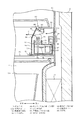
霧化ユニット38には、図7に示すように、給電ピン54が後方へ向けて突出するように設けられている。この給電ピン54は、基端部が導電部材55を介して前記導電性シート46に接続されている。霧化ユニット38をユニット収容部41内の正規の位置にセットすると、給電ピン54の先端部が、ベース板37側に設けられたコネクタ58に挿入接続される。コネクタ58は、電源装置56の二次側の高電圧トランス57の一端に接続されるようになっている。ここで、前記ミスト放出部49には、導電性シート46、給電ピン54、コネクタ58を介して、電源装置56の負の高電圧が印加されるようになっている。電源装置56の負の高電圧が各ミスト放出部49に印加されると、各ミスト放出部49の表面の水分が分裂して微細なミストとして放出されるようになる。静電霧化装置36において、ミスト放出部49に対する対極を、当該ミスト放出部49の近傍には設置していない。   As shown in FIG. 7, the atomizing unit 38 is provided with a power supply pin 54 so as to protrude rearward. The power supply pin 54 is connected to the conductive sheet 46 through a conductive member 55 at the base end. When the atomizing unit 38 is set at a regular position in the unit accommodating portion 41, the distal end portion of the power supply pin 54 is inserted and connected to a connector 58 provided on the base plate 37 side. The connector 58 is connected to one end of the secondary high voltage transformer 57 of the power supply device 56. Here, the negative high voltage of the power supply device 56 is applied to the mist emitting portion 49 via the conductive sheet 46, the power feed pin 54, and the connector 58. When a negative high voltage of the power supply device 56 is applied to each mist emitting portion 49, the moisture on the surface of each mist emitting portion 49 is split and released as fine mist. In the electrostatic atomizer 36, the counter electrode for the mist emitting unit 49 is not installed in the vicinity of the mist emitting unit 49.

ユニット収容部41内の底部には、霧化ユニット38の位置決めをする位置決め凸部60が設けられているとともに、霧化ユニット38のセット状態を検出するユニット検出スイッチ61が設けられている。また、ベース板37の前部には、蓋スイッチ62及びレバー63が設けられている。蓋40が閉鎖された状態では、蓋40の押圧部64を介してレバー63が回動されることに基づき蓋スイッチ62が押圧操作され、蓋40が開放されると、蓋スイッチ62に対する押圧操作が解除される。これにより、蓋40の開閉を蓋スイッチ62により検出する。   A positioning convex portion 60 for positioning the atomizing unit 38 is provided at the bottom of the unit accommodating portion 41, and a unit detection switch 61 for detecting the set state of the atomizing unit 38 is provided. Further, a lid switch 62 and a lever 63 are provided at the front portion of the base plate 37. When the lid 40 is closed, the lid switch 62 is pressed based on the lever 63 being rotated via the pressing portion 64 of the lid 40, and when the lid 40 is opened, the pressing operation to the lid switch 62 is performed. Is released. Thereby, the opening / closing of the lid 40 is detected by the lid switch 62.

前記貯水タンク43内には、図7に示すように、容器状をなすろ過フィルタ65が設けられているとともに、そのろ過フィルタ65内にイオン交換樹脂66が収容されている。ユニット蓋45には、そのろ過フィルタ65に対応して下方へ延びる筒状の注水口67が設けられている。ユニット蓋45には、その注水口67を開閉する注水蓋68が着脱可能に装着されている。その注水蓋68を外した状態で、注水口67から貯水タンク43内へ水を補給することができる。補給された水は、ろ過フィルタ65によりろ過することができる。また、貯水タンク43の内面には、例えば酸化チタンからなる光触媒69が塗布されている。ユニット収容部41内の底部には、紫外線を発する光源(例えば紫外線LED)70が設けられている。この光源70は、点灯時に貯水タンク43に向けて紫外線を照射する。光触媒69は、その紫外線を受けることで活性化し、除菌作用を発揮する。ここで、ろ過フィルタ65、イオン交換樹脂66、光触媒69は、本発明の浄水手段を構成する。   As shown in FIG. 7, the water storage tank 43 is provided with a filtration filter 65 having a container shape, and an ion exchange resin 66 is accommodated in the filtration filter 65. The unit lid 45 is provided with a cylindrical water inlet 67 extending downward corresponding to the filtration filter 65. The unit lid 45 is detachably mounted with a water injection lid 68 that opens and closes the water injection port 67. With the water injection lid 68 removed, water can be supplied from the water injection port 67 into the water storage tank 43. The replenished water can be filtered by the filtration filter 65. Further, a photocatalyst 69 made of, for example, titanium oxide is applied to the inner surface of the water storage tank 43. A light source (for example, an ultraviolet LED) 70 that emits ultraviolet rays is provided at the bottom of the unit housing portion 41. The light source 70 irradiates ultraviolet rays toward the water storage tank 43 when turned on. The photocatalyst 69 is activated by receiving the ultraviolet rays and exhibits a sterilizing action. Here, the filtration filter 65, the ion exchange resin 66, and the photocatalyst 69 constitute the water purifying means of the present invention.

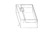
前記野菜室4内には、図1に示すように、下部容器72と、この下部容器72の上部に配置された上部容器73とが設けられている。上部容器73は、下部容器72よりも前後方向の長さが小さく形成されていて、下部容器72の後部側に配置されている。上部容器73の前端部が、前記ベース板37の前記ミスト放出口52の下方に位置するようになっている。そして、この状態で、ミスト放出口52から野菜室4内へミストが放出されると、そのミストは下部容器72と上部容器73の両方に供給されるようになる。   In the vegetable compartment 4, as shown in FIG. 1, a lower container 72 and an upper container 73 disposed on the lower container 72 are provided. The upper container 73 is formed to have a length in the front-rear direction smaller than that of the lower container 72, and is disposed on the rear side of the lower container 72. A front end portion of the upper container 73 is positioned below the mist discharge port 52 of the base plate 37. In this state, when mist is discharged from the mist discharge port 52 into the vegetable compartment 4, the mist is supplied to both the lower container 72 and the upper container 73.

冷蔵庫本体1の背部には、マイクロコンピュータを含む制御装置75(図1参照)が設けられている。この制御装置75は、冷凍サイクルのコンプレッサ19や冷蔵用ファン14、冷凍用ファン17、自動製氷装置12、給水機構29のポンプ用モータ30、静電霧化装置36、光源70など、冷蔵庫本体1の全体の動作を制御する機能を有していて、制御手段を構成する。制御装置75は、特に、静電霧化装置36に対しては、各貯蔵室の扉スイッチが扉の閉鎖を検出し、かつ、前記蓋スイッチ62が蓋40の閉鎖を検出し、さらに、ユニット検出スイッチ61が霧化ユニット38のセット状態を検出した状態でのみ静電霧化装置36への通電を許容するが、いずれかの貯蔵室の扉が開放されたり、蓋40が開放されたり、或いは霧化ユニット38がセットされていないことを検出した場合には、静電霧化装置36への通電を遮断する。また、制御装置75は、所定時間ごとに光源70を一定時間点灯制御する。   On the back of the refrigerator main body 1, a control device 75 (see FIG. 1) including a microcomputer is provided. The control device 75 includes the refrigerator main body 1 such as the compressor 19 of the refrigeration cycle, the refrigeration fan 14, the refrigeration fan 17, the automatic ice making device 12, the pump motor 30 of the water supply mechanism 29, the electrostatic atomizer 36, and the light source 70. Has a function of controlling the overall operation of the apparatus, and constitutes a control means. In particular, for the electrostatic atomizer 36, the control device 75 detects that the door switch of each storage chamber detects the closing of the door, and the lid switch 62 detects the closure of the lid 40. Only when the detection switch 61 detects the set state of the atomizing unit 38, energization to the electrostatic atomizer 36 is allowed, but the door of any storage chamber is opened, the lid 40 is opened, Or when it detects that the atomization unit 38 is not set, the electricity supply to the electrostatic atomizer 36 is interrupted | blocked. In addition, the control device 75 performs lighting control of the light source 70 for a predetermined time every predetermined time.

上記構成の作用を説明する。
霧化ユニット38がユニット収容部41内にセットされ、ユニット収容部41の蓋40が閉鎖され、かつ、各貯蔵室の扉が閉鎖された状態で、静電霧化装置36が駆動されると、各ミスト放出部49から微細なミストが放出され、そのミストがミスト放出口52から野菜室4の上部容器73及び下部容器72内に供給される。そのミストは強い酸化作用を有するヒドロキシラジカルを含んでいて、そのヒドロキシラジカルを含むミストが野菜室4の上部容器73及び下部容器72内に供給されることで、それらの除菌や脱臭が可能になる。また、そのミストにより、それら上部容器73及び下部容器72内に収容された野菜等の鮮度保持等も期待できる。また、所定時間ごとに光源70を一定時間点灯制御することで、貯水タンク43内の光触媒69が活性化され、貯水タンク43内の除菌作用を期待できる。
The operation of the above configuration will be described.
When the atomizing unit 38 is set in the unit accommodating portion 41, the lid 40 of the unit accommodating portion 41 is closed, and the door of each storage chamber is closed, the electrostatic atomizing device 36 is driven. Fine mist is discharged from each mist discharge portion 49, and the mist is supplied from the mist discharge port 52 into the upper container 73 and the lower container 72 of the vegetable compartment 4. The mist contains a hydroxy radical having a strong oxidizing action, and the mist containing the hydroxy radical is supplied into the upper container 73 and the lower container 72 of the vegetable room 4 so that they can be sterilized and deodorized. Become. Moreover, the freshness maintenance of the vegetables etc. which were accommodated in these upper container 73 and lower container 72 by the mist can also be expected. In addition, by controlling lighting of the light source 70 for a predetermined time every predetermined time, the photocatalyst 69 in the water storage tank 43 is activated, and a sterilization action in the water storage tank 43 can be expected.

ところで、静電霧化装置36は、水が無くなるとミストを発生させることができなくなるため、定期的に水を補給する必要がある。また、使用に伴いミスト放出部49の表面にぬめりのような汚れが付着して目詰まりが発生すると、ミストの放出性能が低下するため、例えば1年に1回程度、ミスト放出部49を掃除することが好ましい。   By the way, since the electrostatic atomizer 36 cannot generate mist when water runs out, it is necessary to replenish water regularly. Further, when dirt such as slime adheres to the surface of the mist discharge portion 49 with use and clogging occurs, the mist discharge performance deteriorates. For example, the mist discharge portion 49 is cleaned about once a year. It is preferable to do.

このような場合には、冷蔵室3の扉3aを開放した後、仕切板8前部8aの蓋40をスライドさせてユニット収容部41の開口部39を開放させる。そして、使用者はユニット収容部41内に手を挿入して静電霧化装置36の霧化ユニット38を持ち、前方へスライドさせた後、持ち上げ、ユニット収容部41から取り出す。このとき、コネクタ58に対する給電ピン54の接続が外れる。そして、水を補給するだけの場合には、注水蓋68を外した状態で注水口67から水を補給する。また、ミスト放出部49も掃除する場合には、貯水タンク43から上部ケース44を外すとともに、上部ケース44から放出部カバー50を外し、ミスト放出部49を露出させた状態でその掃除を行う。なお、水を補給するだけの場合には、霧化ユニット38をユニット収容部41にセットしたままで、注水蓋68のみを外すことによっても行うことができる。   In such a case, after opening the door 3a of the refrigerator compartment 3, the lid 40 of the front portion 8a of the partition plate 8 is slid to open the opening 39 of the unit accommodating portion 41. And a user inserts a hand in the unit accommodating part 41, has the atomizing unit 38 of the electrostatic atomizer 36, slides it forward, lifts, and takes out from the unit accommodating part 41. FIG. At this time, the power feed pin 54 is disconnected from the connector 58. Then, when only replenishing water, water is replenished from the water filling port 67 with the water filling lid 68 removed. When cleaning the mist discharge portion 49, the upper case 44 is removed from the water storage tank 43, and the discharge portion cover 50 is removed from the upper case 44, and the mist discharge portion 49 is exposed and cleaned. In addition, when only replenishing water, it can also carry out by removing only the water injection lid | cover 68, with the atomization unit 38 set to the unit accommodating part 41. FIG.

なお、水の補給や掃除が終わったら、霧化ユニット38をもとのように組み立てた後、霧化ユニット38をユニット収容部41内に収容して正規の位置にセットする。このとき、給電ピン54をコネクタ58に挿入接続する。この後、蓋40を前方へスライドして開口部39を閉鎖し、冷蔵室3の扉3aを閉鎖しておく。   When replenishment or cleaning of water is completed, the atomization unit 38 is assembled as before, and then the atomization unit 38 is accommodated in the unit accommodating portion 41 and set in a proper position. At this time, the power feed pin 54 is inserted and connected to the connector 58. Thereafter, the lid 40 is slid forward to close the opening 39, and the door 3a of the refrigerator compartment 3 is closed.

上記した参考形態によれば、次のような作用効果を得ることができる。
冷蔵室3と野菜室4との間の仕切板8に静電霧化装置36を設置し、その静電霧化装置36のミスト放出部49から放出されたミストを主に野菜室4に供給する構成とした。これにより、強い酸化作用を有するヒドロキシラジカルを含むミストが野菜室4に供給されることで、その野菜室4内の除菌や脱臭が可能になる。また、そのミストにより、野菜等の鮮度保持等も期待できる。
According to the reference embodiment described above, the following operational effects can be obtained.
The electrostatic atomizer 36 is installed in the partition plate 8 between the refrigerator compartment 3 and the vegetable compartment 4, and the mist discharged from the mist discharge part 49 of the electrostatic atomizer 36 is mainly supplied to the vegetable compartment 4. It was set as the structure to do. Thereby, the mist containing the hydroxy radical which has a strong oxidizing action is supplied to the vegetable compartment 4, so that sterilization and deodorization in the vegetable compartment 4 can be performed. The mist can also be expected to maintain the freshness of vegetables and the like.

静電霧化装置36としては、ミスト放出部49に対する対極を、当該ミスト放出部49の近傍に設置していないため、ミスト放出部と対極との間でコロナ放電が発生していた従来構成のものとは異なり、オゾンなどの有害ガスの発生を抑えることができ、安全性を向上させることができる。   The electrostatic atomizer 36 has a conventional configuration in which a corona discharge is generated between the mist emitting portion and the counter electrode because the counter electrode for the mist emitting portion 49 is not installed in the vicinity of the mist emitting portion 49. Unlike things, generation of harmful gases such as ozone can be suppressed, and safety can be improved.

静電霧化装置36は水Wを貯留する貯水タンク43を有し、この貯水タンク43に貯留された水Wを、吸水ピン48、保水材47及び導電性シート46を介して各ミスト放出部49に供給する構成としている。これにより、ミスト放出部49へ水を安定して供給することができるので、ミスト放出部49からのミスト発生量も安定させることができる。
また、貯水タンク43は霧化ユニット38ごとユニット収容部41に対して着脱可能であるから、貯水タンク43への水の補給を容易に行うことができる。貯水タンク43に合わせてミスト放出部49も着脱可能であるから、そのミスト放出部49の掃除も容易に行うことができる。
The electrostatic atomizer 36 has a water storage tank 43 for storing water W, and the water W stored in the water storage tank 43 is supplied to each mist discharge section via a water absorption pin 48, a water retention material 47 and a conductive sheet 46. 49. Thereby, since water can be stably supplied to the mist discharge part 49, the amount of mist generated from the mist discharge part 49 can also be stabilized.
Moreover, since the water storage tank 43 can be attached to and detached from the unit housing portion 41 together with the atomization unit 38, water can be easily supplied to the water storage tank 43. Since the mist discharge part 49 can also be attached and detached according to the water storage tank 43, the mist discharge part 49 can also be cleaned easily.

貯水タンク43内にろ過フィルタ65を設けたので、貯水タンク43内に補給される水を浄化することができ、清潔な水をミスト放出部49に供給することができる。これにより、ミスト放出部49などに目詰まりが発生することを極力防止することができ、ミストの放出量の低下を防止することができるようになる。また、そのろ過フィルタ65内にイオン交換樹脂66を設けたので、貯水タンク43内に貯留される水Wに含まれたミネラル分を、そのイオン交換樹脂66により吸着することで除去することができる。これにより、ミスト放出部49などにスケールが蓄積してしまうことを極力防止できて、目詰まりの発生を一層防止することができ、ミストの放出量の低下を一層防止できるようになる。これらにより、ミスト放出部49の使用寿命を長くすることが可能になる。
加えて、所定時間ごとに光源70を一定時間点灯制御することで、貯水タンク43内の光触媒69が活性化され、貯水タンク43内の除菌作用を期待できる。これによっても、清潔な水をミスト放出部49に供給することができる。
Since the filtration filter 65 is provided in the water storage tank 43, the water replenished in the water storage tank 43 can be purified, and clean water can be supplied to the mist discharge section 49. As a result, the occurrence of clogging in the mist discharge portion 49 and the like can be prevented as much as possible, and a decrease in the amount of mist discharged can be prevented. In addition, since the ion exchange resin 66 is provided in the filtration filter 65, minerals contained in the water W stored in the water storage tank 43 can be removed by adsorbing the ion exchange resin 66. . As a result, it is possible to prevent the scale from accumulating in the mist discharge portion 49 as much as possible, to further prevent clogging, and to further prevent a decrease in the amount of mist discharged. As a result, the service life of the mist discharge part 49 can be extended.
In addition, by controlling lighting of the light source 70 for a predetermined time every predetermined time, the photocatalyst 69 in the water storage tank 43 is activated, and a sterilization action in the water storage tank 43 can be expected. Also by this, clean water can be supplied to the mist discharge part 49.

静電霧化装置36の霧化ユニット38は仕切板8の前部8aに設置したので、その霧化ユニット38に対する水の補給や、霧化ユニット38の着脱が容易にできる。霧化ユニット38のミスト放出部49から放出されるミストが、野菜室4における上部容器73と下部容器72の両方に上方から供給される構成としたので、上部容器73にも下部容器72にもミストを供給することができる。   Since the atomization unit 38 of the electrostatic atomizer 36 is installed in the front portion 8a of the partition plate 8, water can be replenished to the atomization unit 38 and the atomization unit 38 can be easily attached and detached. Since the mist discharged from the mist discharge portion 49 of the atomization unit 38 is supplied from above to both the upper container 73 and the lower container 72 in the vegetable compartment 4, both the upper container 73 and the lower container 72 are provided. Mist can be supplied.

ミスト放出部49に白金ナノコロイドを担持させることで、ミスト放出部49から放出されるミストにヒドロキシラジカルが一層生成されやすくなり、除菌機能や脱臭機能を一層向上させることが可能になる。また、ミスト放出部49に導電性物質(カーボン)を含ませたことにより、ミスト放出部49の導電性を良好に維持することができる。   By supporting the platinum nanocolloid on the mist releasing part 49, hydroxy radicals are more easily generated in the mist released from the mist releasing part 49, and the sterilization function and the deodorizing function can be further improved. In addition, since the conductive material (carbon) is included in the mist emitting portion 49, the conductivity of the mist emitting portion 49 can be maintained well.

貯蔵室(冷蔵室3、野菜室4、製氷室5、小冷凍室、冷凍室7)の扉3a、4a,5a,6a,7aのどれかが開放されると、静電霧化装置36の通電が遮断される構成としているので、使用者が高電圧部に触れることを防止でき、安全性の向上を図ることができる。この場合、少なくとも冷蔵室3の扉3aが開放されたときに、静電霧化装置36の通電が遮断される構成とすればよい。また、本実施形態においては、静電霧化装置36を収容したユニット収容部41の蓋40の開閉を検出する蓋スイッチ62を設け、その蓋40が開放されたときも、静電霧化装置36の通電が遮断されるようにしているので、一層安全性を向上できる。さらに、ユニット収容部41にユニット検出スイッチ61を設け、霧化ユニット38がセットされていないときも、静電霧化装置36の通電が遮断されるようにしているので、一層安全性を向上できる。   When one of the doors 3a, 4a, 5a, 6a, 7a of the storage room (refrigeration room 3, vegetable room 4, ice making room 5, small freezer room, freezer room 7) is opened, the electrostatic atomizer 36 Since it is set as the structure by which electricity supply is interrupted | blocked, it can prevent that a user touches a high voltage part and can aim at the improvement of safety | security. In this case, at least when the door 3a of the refrigerator compartment 3 is opened, the energization of the electrostatic atomizer 36 may be cut off. Moreover, in this embodiment, the lid | cover switch 62 which detects opening / closing of the lid | cover 40 of the unit accommodating part 41 which accommodated the electrostatic atomizer 36 is provided, and when the lid | cover 40 is open | released, an electrostatic atomizer Since the energization of 36 is cut off, the safety can be further improved. Furthermore, since the unit detection switch 61 is provided in the unit accommodating portion 41 so that the energization of the electrostatic atomizer 36 is cut off even when the atomizing unit 38 is not set, the safety can be further improved. .

(第1の実施形態)
次に本発明の第1の実施形態について図8を参照して説明する。なお、参考形態と同一部分には同一の符号を付して説明は省略し、異なる部分について説明する。
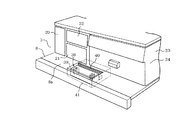
この実施形態における静電霧化装置80は、冷蔵室3内の後部において、チルド室23の上方で、かつ冷気ダクト15の冷気吹出し口15aの前方に位置させて設置されている。静電霧化装置80の霧化ユニット81を収容するユニットベース82は、チルド室23の上方に設置された下部棚板83上に固定されている。
(First embodiment)
Next, a first embodiment of the present invention will be described with reference to FIG. In addition, the same code | symbol is attached | subjected to the same part as a reference form, description is abbreviate | omitted, and a different part is demonstrated.
The electrostatic atomizer 80 in this embodiment is installed in the rear part in the refrigerator compartment 3 above the chilled chamber 23 and in front of the cold air outlet 15a of the cold air duct 15. A unit base 82 that accommodates the atomization unit 81 of the electrostatic atomizer 80 is fixed on a lower shelf 83 installed above the chilled chamber 23.

ユニットベース82は、後面及び前面が開口していて、前面に前面開口部を開閉する蓋84が設けられている。蓋84は、上端部が軸85にてユニットベース82に回動可能に支持されていて、その軸85を支点に前後方向に回動可能とされている。ユニットベース82の上部には、蓋84の開閉を検出する蓋スイッチ86が設けられている。下部棚板83にはストッパ部87が設けられている。このストッパ部87は、蓋84が開放方向に移動することを規制するためのもので、使用者が蓋84を開放させる際にはその規制を解除することができるようになっている。蓋84には、ミストを通過させるためのミスト放出口88が形成されている。   The unit base 82 has a rear surface and a front surface that are open, and a lid 84 that opens and closes the front opening is provided on the front surface. The lid 84 is rotatably supported by the unit base 82 at the upper end portion by a shaft 85, and can be rotated in the front-rear direction with the shaft 85 as a fulcrum. A lid switch 86 for detecting opening / closing of the lid 84 is provided on the upper portion of the unit base 82. The lower shelf plate 83 is provided with a stopper portion 87. The stopper 87 is for restricting the movement of the lid 84 in the opening direction, and the restriction can be released when the user opens the lid 84. The lid 84 is formed with a mist discharge port 88 for allowing the mist to pass therethrough.

霧化ユニット81は、貯水タンク90(給水部、貯水部に相当)と、ピン状をなす複数本のミスト放出部91と、導電性シート92と、保水材93と、吸水ピン94と、放出部カバー95とを有していて、ユニットベース82に対して前方から出し入れ可能に収納されるようになっている。   The atomization unit 81 includes a water storage tank 90 (corresponding to a water supply unit and a water storage unit), a plurality of pin-like mist discharge units 91, a conductive sheet 92, a water retention material 93, a water absorption pin 94, and a discharge. And a unit cover 95 so that the unit base 82 can be inserted and removed from the front.

ミスト放出部91、導電性シート92、保水材93、吸水ピン94は、第1の実施形態におけるミスト放出部49、導電性シート46、保水材47、吸水ピン48と同種の材料により形成されている。各ミスト放出部91は、下端部が導電性シート92に接触し、先細状をなす上端部が上に向けられている。導電性シート92の下に保水材93が配置されている。吸水ピン94は、上端部が保水材93を貫通して導電性シート92に接触し、下端部が貯水タンク90内に貯留された水Wの中に挿入されている。   The mist discharge portion 91, the conductive sheet 92, the water retention material 93, and the water absorption pin 94 are formed of the same material as the mist discharge portion 49, the conductive sheet 46, the water retention material 47, and the water absorption pin 48 in the first embodiment. Yes. Each mist discharge portion 91 has a lower end portion in contact with the conductive sheet 92 and a tapered upper end portion directed upward. A water retention material 93 is disposed under the conductive sheet 92. The water absorption pin 94 has an upper end penetrating the water retaining material 93 to contact the conductive sheet 92 and a lower end inserted into the water W stored in the water storage tank 90.

貯水タンク90内の後部には、容器状をなすろ過フィルタ96が設けられ、このろ過フィルタ96内にイオン交換樹脂97が収容されている。この場合も、ろ過フィルタ96及びイオン交換樹脂97は浄水手段を構成する。貯水タンク90の上部には、ろ過フィルタ96の上方に位置させて注水口98が形成されている。   A filtration filter 96 having a container shape is provided at the rear of the water storage tank 90, and an ion exchange resin 97 is accommodated in the filtration filter 96. Also in this case, the filtration filter 96 and the ion exchange resin 97 constitute water purification means. A water injection port 98 is formed above the water storage tank 90 so as to be positioned above the filtration filter 96.

冷気ダクト15には、貯水タンク90の上方に位置させて冷却板99が配置されている。この冷却板99は、熱伝導率の高い金属材料、例えば鉄板によりほぼコ字形に形成されていて、開口部が下向きとなるように配置されている。この冷却板99の一端部99aは、冷気ダクト15を貫通して当該冷気ダクト15内に配置され、他端部99bは冷蔵室3内に突出して、前記注水口98の上方に配置されている。他端部99bの下端部が、注水口98に上方から臨んでいる。   In the cold air duct 15, a cooling plate 99 is disposed above the water storage tank 90. The cooling plate 99 is formed in a substantially U shape by a metal material having a high thermal conductivity, for example, an iron plate, and is arranged so that the opening portion faces downward. One end portion 99 a of the cooling plate 99 passes through the cold air duct 15 and is disposed in the cold air duct 15, and the other end portion 99 b projects into the refrigerator compartment 3 and is disposed above the water inlet 98. . The lower end portion of the other end portion 99b faces the water injection port 98 from above.

この場合、冷却板99の一端部99aが、冷気ダクト15内を流れる冷気により冷却されるため、それに伴い他端部99bも冷却される。これに伴い、冷蔵室3内において、その他端部99bの周囲の空気に含まれた水蒸気がその他端部99bの表面に結露し、その結露水W1が注水口98から貯水タンク90内に滴下し、貯留されるようになる。したがって、庫内の湿気を凝縮した結露水W1が貯水タンク90に貯留される。その貯水タンク90に貯留された水Wは、吸水ピン94に吸い上げられ、保水材93及び導電性シート92を介してミスト放出部91へ供給される。この場合、吸水ピン94、保水材93、導電性シート92は、ミスト放出部91へ水分を供給する給水部を構成する。貯水タンク90は、給水部と貯水部を兼ねている。   In this case, since the one end 99a of the cooling plate 99 is cooled by the cold air flowing through the cold air duct 15, the other end 99b is also cooled accordingly. Accordingly, in the refrigerating chamber 3, water vapor contained in the air around the other end 99b is condensed on the surface of the other end 99b, and the condensed water W1 is dripped from the water injection port 98 into the water storage tank 90. , Will be stored. Therefore, the dew condensation water W <b> 1 obtained by condensing moisture in the cabinet is stored in the water storage tank 90. The water W stored in the water storage tank 90 is sucked up by the water absorption pins 94 and supplied to the mist discharge unit 91 via the water retention material 93 and the conductive sheet 92. In this case, the water absorption pins 94, the water retention material 93, and the conductive sheet 92 constitute a water supply unit that supplies moisture to the mist discharge unit 91. The water storage tank 90 serves as both a water supply unit and a water storage unit.

前記放出部カバー95はミスト放出部91を覆うように配置され、ミストが通過する多数の孔を有している。霧化ユニット81には、図示はしないが、後方に向けて突出する給電ピンが設けられていて、霧化ユニット81を正規の位置にセットすることに伴い、その給電ピンが、ユニットベース82側に設けられた図示しないコネクタに挿入接続されるようになっている。この場合も、ミスト放出部91には、導電性シート92、給電ピン及びコネクタを介して、電源装置の負の高電圧が印加されるようになっている。電源装置の負の高電圧が各ミスト放出部91に印加されると、各ミスト放出部91の表面の水分が分裂して微細なミストとして放出されるようになる。静電霧化装置80において、ミスト放出部91に対する対極を、当該ミスト放出部91の近傍には設置していない。   The discharge part cover 95 is arranged so as to cover the mist discharge part 91 and has a large number of holes through which the mist passes. Although not shown, the atomizing unit 81 is provided with a power feeding pin that protrudes rearward, and the power feeding pin is set to the unit base 82 side when the atomizing unit 81 is set at a normal position. It is inserted and connected to a connector (not shown) provided in FIG. Also in this case, a negative high voltage of the power supply device is applied to the mist emitting portion 91 via the conductive sheet 92, the power feed pin, and the connector. When a negative high voltage of the power supply device is applied to each mist emitting portion 91, the moisture on the surface of each mist emitting portion 91 is split and released as fine mist. In the electrostatic atomizer 80, the counter electrode for the mist emitting unit 91 is not installed in the vicinity of the mist emitting unit 91.

上記構成において、静電霧化装置80が駆動されると、各ミスト放出部91からヒドロキシラジカルを含む微細なミストが放出される。そのミストは、冷気ダクト15の冷気吹出し口15aから冷蔵室3内に吹き出される冷気の流れととともに、蓋84のミスト放出口88を通して冷蔵室3の前方に向けて供給される(図8の矢印C参照)。冷蔵室3内に供給されたミストは、冷気とともに下方の野菜室4にも供給されるようになる。   In the above configuration, when the electrostatic atomizer 80 is driven, fine mist containing hydroxy radicals is emitted from each mist emitting portion 91. The mist is supplied toward the front of the refrigerating chamber 3 through the mist discharge port 88 of the lid 84 together with the flow of the cold air blown into the refrigerating chamber 3 from the cold air outlet 15a of the cold air duct 15 (FIG. 8). (See arrow C). The mist supplied into the refrigerator compartment 3 is also supplied to the vegetable compartment 4 below together with the cold air.

上記した実施形態によれば、特に次のような作用効果を得ることができる。
静電霧化装置80を、冷蔵室3内において、冷気吹出し口15aの前方に配置しているので、ミスト放出部91から放出されたミストを冷蔵室3及び野菜室4にも供給することができ、それらの除菌及び脱臭の作用を期待することができる。また、そのミストにより、野菜等の鮮度保持等も期待できる。
According to the above-described embodiment, the following operational effects can be obtained.
Since the electrostatic atomizer 80 is disposed in the refrigerator compartment 3 in front of the cold air outlet 15a, the mist discharged from the mist discharger 91 can be supplied to the refrigerator compartment 3 and the vegetable compartment 4 as well. And can be expected to have the effect of sterilization and deodorization. The mist can also be expected to maintain the freshness of vegetables and the like.

静電霧化装置80において使用する水として、冷却板99に結露した結露水W1(庫内の水蒸気を凝縮した結露水)を利用しているので、静電霧化装置80への給水を自動化でき、使用者が静電霧化装置80へ給水する手間を極力省くことができる。なお、貯水タンク90へは、使用者が必要に応じて水を補給することもできる。この場合、冷却板99に結露した結露水W1には、庫内の空気に含まれた埃が含まれることが懸念されるが、その結露水W1をろ過フィルタ96にてろ過することで浄化することができる。   As the water used in the electrostatic atomizer 80, the condensed water W1 condensed on the cooling plate 99 (condensed water obtained by condensing water vapor in the cabinet) is used, so water supply to the electrostatic atomizer 80 is automated. It is possible to save as much time as possible for the user to supply water to the electrostatic atomizer 80. The water storage tank 90 can be replenished with water as required by the user. In this case, there is a concern that the condensed water W1 condensed on the cooling plate 99 may contain dust contained in the air in the cabinet, but the condensed water W1 is purified by filtering with the filtration filter 96. be able to.

(第2の実施形態)
次に本発明の第2の実施形態について図9を参照して説明する。なお、参考形態及び第1の実施形態と同一部分には同一の符号を付して説明は省略し、異なる部分について説明する。
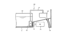
この第2の実施形態においては、庫内の水蒸気を凝縮する手段として、冷却板99に代えて、電子冷却ユニット、この場合ペルチェ素子101の冷却面102を利用している。ペルチェ素子101は、この場合、ユニットベース82の取付片103に取り付けている。そのペルチェ素子101の冷却面102は、冷蔵室3内において、前記注水口98の上方に配置されている。冷却面102の下端部が、注水口98に上方から臨んでいる。
(Second Embodiment)
Next, a second embodiment of the present invention will be described with reference to FIG. Note that the same parts as those in the reference embodiment and the first embodiment are denoted by the same reference numerals, description thereof will be omitted, and different parts will be described.
In the second embodiment, instead of the cooling plate 99, an electronic cooling unit, in this case, the cooling surface 102 of the Peltier element 101 is used as means for condensing the water vapor in the warehouse. In this case, the Peltier element 101 is attached to the attachment piece 103 of the unit base 82. The cooling surface 102 of the Peltier element 101 is disposed above the water inlet 98 in the refrigerator compartment 3. The lower end of the cooling surface 102 faces the water injection port 98 from above.

この場合、ペルチェ素子101の冷却面102が冷却されることに伴い、冷却面102の周囲の空気に含まれた水蒸気がその冷却面102の表面に結露し、その結露水W1が注水口98から貯水タンク90内に滴下し、貯留されるようになる。したがって、この場合も庫内の湿気を凝縮した結露水W1が貯水タンク90に貯留される。その貯水タンク90に貯留された水Wは、吸水ピン94に吸い上げられ、保水材93及び導電性シート92を介してミスト放出部91へ供給される。この場合も、吸水ピン94、保水材93、導電性シート92は、ミスト放出部91へ水分を供給する給水部を構成する。貯水タンク90は給水部と貯水部を兼ねている。
このような構成とした第2の実施形態においても第1の実施形態と同様な作用効果を得ることができる。
In this case, as the cooling surface 102 of the Peltier element 101 is cooled, water vapor contained in the air around the cooling surface 102 is condensed on the surface of the cooling surface 102, and the condensed water W 1 is discharged from the water inlet 98. It dripped in the water storage tank 90 and comes to be stored. Therefore, also in this case, the dew condensation water W <b> 1 obtained by condensing moisture in the storage is stored in the water storage tank 90. The water W stored in the water storage tank 90 is sucked up by the water absorption pins 94 and supplied to the mist discharge unit 91 via the water retention material 93 and the conductive sheet 92. Also in this case, the water absorption pins 94, the water retention material 93, and the conductive sheet 92 constitute a water supply unit that supplies moisture to the mist discharge unit 91. The water storage tank 90 serves as both a water supply unit and a water storage unit.
Also in the second embodiment having such a configuration, the same effects as those of the first embodiment can be obtained.

(その他の実施形態)
浄水手段としては、ろ過フィルタ65,96内に収容したイオン交換樹脂66,97に代えて活性炭を用いてもよい。
光触媒69としては、酸化チタンに限られず、可視光型光触媒を用いてもよい。可視光型光触媒を用いた場合には、光源70も可視光型光源でよい。
(Other embodiments)
As the water purification means, activated carbon may be used instead of the ion exchange resins 66 and 97 housed in the filtration filters 65 and 96.
The photocatalyst 69 is not limited to titanium oxide, and a visible light photocatalyst may be used. When a visible light type photocatalyst is used, the light source 70 may also be a visible light type light source.

図面中、3は冷蔵室(貯蔵室)、4は野菜室(貯蔵室)、8は仕切板、15は冷気ダクト、15aは冷気吹出し口、20は製氷用給水タンク(貯水部)、36は静電霧化装置、38は霧化ユニット、40は蓋、43は貯水タンク(給水部、貯水部)、46は導電性シート(給水部)、47は保水材(給水部)、48は吸水ピン(給水部)、49はミスト放出部、54は給電ピン、56は電源装置、65はろ過フィルタ(浄水手段)、66はイオン交換樹脂(浄水手段)、69は光触媒、70は光源、75は制御装置、80は静電霧化装置、81は霧化ユニット、84は蓋、88はミスト放出口、90は貯水タンク(給水部、貯水部)、91はミスト放出部、92は導電性シート(給水部)、93は保水材(給水部)、94は吸水ピン(給水部)、95は放出部カバー、96はろ過フィルタ(浄水手段)、97はイオン交換樹脂、99は冷却板、101はペルチェ素子、102は冷却面を示す。   In the drawing, 3 is a refrigeration room (storage room), 4 is a vegetable room (storage room), 8 is a partition plate, 15 is a cold air duct, 15a is a cold air outlet, 20 is a water supply tank for ice making (water storage part), and 36 is Electrostatic atomizer, 38 is an atomizing unit, 40 is a lid, 43 is a water storage tank (water supply part, water storage part), 46 is a conductive sheet (water supply part), 47 is a water retention material (water supply part), and 48 is water absorption. Pin (water supply part), 49 is a mist discharge part, 54 is a power supply pin, 56 is a power supply device, 65 is a filtration filter (water purification means), 66 is an ion exchange resin (water purification means), 69 is a photocatalyst, 70 is a light source, 75 Is a control device, 80 is an electrostatic atomizer, 81 is an atomization unit, 84 is a lid, 88 is a mist discharge port, 90 is a water storage tank (water supply unit, water storage unit), 91 is a mist discharge unit, and 92 is conductive Sheet (water supply part), 93 is a water retaining material (water supply part), 94 is a water absorption pin (water supply part) , 95 release cover, 96 filtration filter (water purification device), 97 is an ion exchange resin, 99 cooling plate, 101 Peltier element 102 indicates a cooling surface.

Claims (8)

冷蔵温度帯の貯蔵室を有する冷蔵庫において、
ミスト放出部と、このミスト放出部に水分を供給する給水部と、前記ミスト放出部に負の高電圧を印加して前記ミスト放出部からミストを放出させるための電源装置とを有する構成の静電霧化装置を前記貯蔵室内の後部に備え、
前記ミスト放出部から放出されたミストを前記貯蔵室に供給する構成とし、
前記ミスト放出部を、前記貯蔵室へ冷気を吹き出す冷気ダクトの冷気吹出し口の前方に設置したことを特徴とする冷蔵庫。
In a refrigerator having a storage room in a refrigerated temperature zone,
A static electricity generator having a mist discharge section, a water supply section for supplying moisture to the mist discharge section, and a power supply device for applying a negative high voltage to the mist discharge section to discharge the mist from the mist discharge section. Equipped with an electroatomizer at the rear of the storage chamber;
The mist discharged from the mist discharge unit is configured to be supplied to the storage chamber,
The refrigerator characterized by installing the said mist discharge | release part in front of the cold-air outlet of the cold-air duct which blows off cold air to the said store room.
前記ミスト放出部の前方にミスト放出口が設けられ、
前記ミスト放出部から放出されるミストは、前記冷気吹出し口から前記貯蔵室内へ供給される冷気の流れとともに前記ミスト放出口を通して前記貯蔵室の前方に向けて供給されることを特徴とする請求項1記載の冷蔵庫。
A mist discharge port is provided in front of the mist discharge part,
The mist discharged from the mist discharge part is supplied toward the front of the storage chamber through the mist discharge port together with a flow of cold air supplied from the cold air outlet to the storage chamber. The refrigerator according to 1.
前記給水部は、前記冷気ダクト内を流れる冷気により冷却することによって庫内の湿気を凝縮した結露水を前記ミスト放出部に供給し、前記ミスト放出部は、前記結露水をミストとして放出することを特徴とする請求項1または2記載の冷蔵庫。   The water supply unit supplies condensed water condensed moisture in the warehouse by cooling with cold air flowing in the cold air duct to the mist discharge unit, and the mist discharge unit discharges the condensed water as mist. The refrigerator according to claim 1 or 2. 前記給水部は、ペルチェ素子により冷却することによって庫内の湿気を凝縮した結露水を前記ミスト放出部に供給し、前記ミスト放出部は、前記結露水をミストとして放出することを特徴とする請求項1または2記載の冷蔵庫。   The said water supply part supplies the condensed water which condensed the moisture in the store | warehouse | chamber by cooling with a Peltier device to the said mist discharge | release part, The said mist discharge | release part discharge | releases the said condensed water as a mist. Item 3. The refrigerator according to item 1 or 2. 前記給水部は貯水部の水を吸い上げて前記ミスト放出部に供給し、前記貯水部には前記結露水が貯留されることを特徴とする請求項3または4記載の冷蔵庫。   5. The refrigerator according to claim 3, wherein the water supply unit sucks up water from the water storage unit and supplies the water to the mist discharge unit, and the condensed water is stored in the water storage unit. 前記給水部は、水を貯留する貯水部と、この貯水部内の水を吸い上げる吸水ピンと、この吸水ピンが吸い上げた水を保水する保水材と、前記吸水ピンおよび保水材並びに前記ミスト放出部に接触して設けられる導電性シートとを備えていることを特徴とする請求項1〜5のいずれか一項に記載の冷蔵庫。   The water supply unit is in contact with a water storage unit that stores water, a water absorption pin that sucks up water in the water storage unit, a water retention material that retains water sucked up by the water absorption pin, the water absorption pin, the water retention material, and the mist discharge unit The refrigerator as described in any one of Claims 1-5 characterized by the above-mentioned. 前記ミスト放出部は、放出部カバーにより覆われていることを特徴とする請求項1〜6のいずれか一項に記載の冷蔵庫。   The refrigerator according to claim 1, wherein the mist discharge part is covered with a discharge part cover. 前記静電霧化装置は、前記ミスト放出部に対する対極を設置していないことを特徴とする請求項1〜7のいずれかに記載の冷蔵庫。   The refrigerator according to any one of claims 1 to 7, wherein the electrostatic atomizer is not provided with a counter electrode for the mist discharger.
JP2012141933A 2012-06-25 2012-06-25 Refrigerator Pending JP2012207911A (en)

Priority Applications (1)

Application Number Priority Date Filing Date Title
JP2012141933A JP2012207911A (en) 2012-06-25 2012-06-25 Refrigerator

Applications Claiming Priority (1)

Application Number Priority Date Filing Date Title
JP2012141933A JP2012207911A (en) 2012-06-25 2012-06-25 Refrigerator

Related Parent Applications (1)

Application Number Title Priority Date Filing Date
JP2009079160A Division JP5537057B2 (en) 2009-03-27 2009-03-27 refrigerator

Publications (1)

Publication Number Publication Date
JP2012207911A true JP2012207911A (en) 2012-10-25

Family

ID=47187794

Family Applications (1)

Application Number Title Priority Date Filing Date
JP2012141933A Pending JP2012207911A (en) 2012-06-25 2012-06-25 Refrigerator

Country Status (1)

Country Link
JP (1) JP2012207911A (en)

Cited By (1)

* Cited by examiner, † Cited by third party
Publication number Priority date Publication date Assignee Title
JP2015117851A (en) * 2013-12-17 2015-06-25 株式会社東芝 Refrigerator

Citations (9)

* Cited by examiner, † Cited by third party
Publication number Priority date Publication date Assignee Title
JP2003079714A (en) * 2001-09-14 2003-03-18 Matsushita Electric Works Ltd Air cleaner
WO2005102101A1 (en) * 2004-04-23 2005-11-03 Matsushita Electric Works, Ltd. Fan heater with electrostatic atomizer
JP2007101034A (en) * 2005-10-03 2007-04-19 Matsushita Electric Ind Co Ltd Refrigerator
JP2008039315A (en) * 2006-08-08 2008-02-21 Matsushita Electric Ind Co Ltd Refrigerator
JP2008116198A (en) * 2004-07-22 2008-05-22 Matsushita Electric Ind Co Ltd Storage and refrigerator using the same
JP2008149242A (en) * 2006-12-15 2008-07-03 Matsushita Electric Works Ltd Electrostatic atomizer
JP2008212887A (en) * 2007-03-07 2008-09-18 Techno Frontier:Kk Electrostatic atomizing device
JP2008238018A (en) * 2007-03-27 2008-10-09 Matsushita Electric Works Ltd Dehumidification system of closed space
JP4179398B1 (en) * 2007-04-26 2008-11-12 松下電器産業株式会社 refrigerator

Patent Citations (9)

* Cited by examiner, † Cited by third party
Publication number Priority date Publication date Assignee Title
JP2003079714A (en) * 2001-09-14 2003-03-18 Matsushita Electric Works Ltd Air cleaner
WO2005102101A1 (en) * 2004-04-23 2005-11-03 Matsushita Electric Works, Ltd. Fan heater with electrostatic atomizer
JP2008116198A (en) * 2004-07-22 2008-05-22 Matsushita Electric Ind Co Ltd Storage and refrigerator using the same
JP2007101034A (en) * 2005-10-03 2007-04-19 Matsushita Electric Ind Co Ltd Refrigerator
JP2008039315A (en) * 2006-08-08 2008-02-21 Matsushita Electric Ind Co Ltd Refrigerator
JP2008149242A (en) * 2006-12-15 2008-07-03 Matsushita Electric Works Ltd Electrostatic atomizer
JP2008212887A (en) * 2007-03-07 2008-09-18 Techno Frontier:Kk Electrostatic atomizing device
JP2008238018A (en) * 2007-03-27 2008-10-09 Matsushita Electric Works Ltd Dehumidification system of closed space
JP4179398B1 (en) * 2007-04-26 2008-11-12 松下電器産業株式会社 refrigerator

Cited By (1)

* Cited by examiner, † Cited by third party
Publication number Priority date Publication date Assignee Title
JP2015117851A (en) * 2013-12-17 2015-06-25 株式会社東芝 Refrigerator

Similar Documents

Publication Publication Date Title
JP6738931B2 (en) refrigerator
KR100626396B1 (en) Humidifier
WO2010109989A1 (en) Electrostatic atomizing device, appliances, air conditioner, and refrigerator
KR20120092442A (en) Refrigerator
JP2008145011A (en) Sterilizing device for refrigerator
KR101162845B1 (en) Refrigerator
JP2008145008A (en) Sterilizing device and refrigerator with sterilizing device
JP5537057B2 (en) refrigerator
JP6479109B2 (en) refrigerator
JP6449134B2 (en) refrigerator
JP6067614B2 (en) refrigerator
JP2012207911A (en) Refrigerator
JP6936906B2 (en) refrigerator
JP2019056553A (en) refrigerator
JP5675940B2 (en) refrigerator
JP5417084B2 (en) refrigerator
JP2011002206A (en) Refrigerator
JP5468330B2 (en) refrigerator
JP2011089681A (en) Refrigerator
JP5523969B2 (en) refrigerator
WO2014109153A1 (en) Refrigerator
JP4895788B2 (en) Water tank device for water supply
JP2008145009A (en) Refrigerator
JP2011052921A (en) Refrigerator
JP2014145585A (en) Refrigerator

Legal Events

Date Code Title Description
A977 Report on retrieval

Free format text: JAPANESE INTERMEDIATE CODE: A971007

Effective date: 20130531

A131 Notification of reasons for refusal

Free format text: JAPANESE INTERMEDIATE CODE: A131

Effective date: 20130611

A521 Written amendment

Free format text: JAPANESE INTERMEDIATE CODE: A523

Effective date: 20130710

A02 Decision of refusal

Free format text: JAPANESE INTERMEDIATE CODE: A02

Effective date: 20140107

A711 Notification of change in applicant

Free format text: JAPANESE INTERMEDIATE CODE: A712

Effective date: 20140207

A521 Written amendment

Free format text: JAPANESE INTERMEDIATE CODE: A523

Effective date: 20140221