JP2012206860A - Sheet feeding apparatus and image forming apparatus - Google Patents

Sheet feeding apparatus and image forming apparatus Download PDF

Info

Publication number
JP2012206860A
JP2012206860A JP2011249811A JP2011249811A JP2012206860A JP 2012206860 A JP2012206860 A JP 2012206860A JP 2011249811 A JP2011249811 A JP 2011249811A JP 2011249811 A JP2011249811 A JP 2011249811A JP 2012206860 A JP2012206860 A JP 2012206860A
Authority
JP
Japan
Prior art keywords
sheet
link member
feeding
cam
link
Prior art date
Legal status (The legal status is an assumption and is not a legal conclusion. Google has not performed a legal analysis and makes no representation as to the accuracy of the status listed.)
Granted
Application number
JP2011249811A
Other languages
Japanese (ja)
Other versions
JP5289541B2 (en
Inventor
Masatoshi Takiguchi
正俊 瀧口
Current Assignee (The listed assignees may be inaccurate. Google has not performed a legal analysis and makes no representation or warranty as to the accuracy of the list.)
Canon Inc
Original Assignee
Canon Inc
Priority date (The priority date is an assumption and is not a legal conclusion. Google has not performed a legal analysis and makes no representation as to the accuracy of the date listed.)
Filing date
Publication date
Application filed by Canon Inc filed Critical Canon Inc
Priority to JP2011249811A priority Critical patent/JP5289541B2/en
Priority to US13/406,995 priority patent/US8616545B2/en
Priority to KR1020120023825A priority patent/KR101515267B1/en
Priority to EP12158528.5A priority patent/EP2500303A3/en
Priority to CN201210064868.9A priority patent/CN102674031B/en
Publication of JP2012206860A publication Critical patent/JP2012206860A/en
Application granted granted Critical
Publication of JP5289541B2 publication Critical patent/JP5289541B2/en
Expired - Fee Related legal-status Critical Current
Anticipated expiration legal-status Critical

Links

Images

Classifications

    • BPERFORMING OPERATIONS; TRANSPORTING
    • B65CONVEYING; PACKING; STORING; HANDLING THIN OR FILAMENTARY MATERIAL
    • B65HHANDLING THIN OR FILAMENTARY MATERIAL, e.g. SHEETS, WEBS, CABLES
    • B65H3/00Separating articles from piles
    • B65H3/02Separating articles from piles using friction forces between articles and separator
    • B65H3/06Rollers or like rotary separators
    • B65H3/0607Rollers or like rotary separators cooperating with means for automatically separating the pile from roller or rotary separator after a separation step
    • GPHYSICS
    • G03PHOTOGRAPHY; CINEMATOGRAPHY; ANALOGOUS TECHNIQUES USING WAVES OTHER THAN OPTICAL WAVES; ELECTROGRAPHY; HOLOGRAPHY
    • G03GELECTROGRAPHY; ELECTROPHOTOGRAPHY; MAGNETOGRAPHY
    • G03G15/00Apparatus for electrographic processes using a charge pattern
    • GPHYSICS
    • G03PHOTOGRAPHY; CINEMATOGRAPHY; ANALOGOUS TECHNIQUES USING WAVES OTHER THAN OPTICAL WAVES; ELECTROGRAPHY; HOLOGRAPHY
    • G03GELECTROGRAPHY; ELECTROPHOTOGRAPHY; MAGNETOGRAPHY
    • G03G21/00Arrangements not provided for by groups G03G13/00 - G03G19/00, e.g. cleaning, elimination of residual charge
    • BPERFORMING OPERATIONS; TRANSPORTING
    • B65CONVEYING; PACKING; STORING; HANDLING THIN OR FILAMENTARY MATERIAL
    • B65HHANDLING THIN OR FILAMENTARY MATERIAL, e.g. SHEETS, WEBS, CABLES
    • B65H2402/00Constructional details of the handling apparatus
    • B65H2402/50Machine elements
    • B65H2402/54Springs, e.g. helical or leaf springs
    • BPERFORMING OPERATIONS; TRANSPORTING
    • B65CONVEYING; PACKING; STORING; HANDLING THIN OR FILAMENTARY MATERIAL
    • B65HHANDLING THIN OR FILAMENTARY MATERIAL, e.g. SHEETS, WEBS, CABLES
    • B65H2403/00Power transmission; Driving means
    • B65H2403/50Driving mechanisms
    • B65H2403/51Cam mechanisms
    • B65H2403/512Cam mechanisms involving radial plate cam
    • BPERFORMING OPERATIONS; TRANSPORTING
    • B65CONVEYING; PACKING; STORING; HANDLING THIN OR FILAMENTARY MATERIAL
    • B65HHANDLING THIN OR FILAMENTARY MATERIAL, e.g. SHEETS, WEBS, CABLES
    • B65H2403/00Power transmission; Driving means
    • B65H2403/50Driving mechanisms
    • B65H2403/53Articulated mechanisms
    • B65H2403/531Planar mechanisms
    • BPERFORMING OPERATIONS; TRANSPORTING
    • B65CONVEYING; PACKING; STORING; HANDLING THIN OR FILAMENTARY MATERIAL
    • B65HHANDLING THIN OR FILAMENTARY MATERIAL, e.g. SHEETS, WEBS, CABLES
    • B65H2403/00Power transmission; Driving means
    • B65H2403/50Driving mechanisms
    • B65H2403/53Articulated mechanisms
    • B65H2403/532Crank-and-rocker mechanism
    • BPERFORMING OPERATIONS; TRANSPORTING
    • B65CONVEYING; PACKING; STORING; HANDLING THIN OR FILAMENTARY MATERIAL
    • B65HHANDLING THIN OR FILAMENTARY MATERIAL, e.g. SHEETS, WEBS, CABLES
    • B65H2801/00Application field
    • B65H2801/03Image reproduction devices
    • B65H2801/06Office-type machines, e.g. photocopiers

Abstract

PROBLEM TO BE SOLVED: To provide a sheet feeding apparatus and an image forming apparatus prevented in size enlargement.SOLUTION: A link member 34 is rotatably provided on a lifting plate 22, and when the lifting plate 22 moves up and down, the movement of the link member 34 is guided by a guide 35b disposed in a link guide hole 35. The movement of the link member 34 is regulated so as to hold the lifting plate 22 in a standby position against a biasing force by a feed spring 23 by a holding part 35a disposed at a lower end of the guide 35b until sheet feed is started. Then, when the sheet is fed, the link member 34 is pressed by a feed cam 36 rotating integrally with the feed roller 2 to release the lock of the link member 34 by the holding part 35a in the link guide hole 35 to allow the movement of the link member 34 along the guide 35b.

Description

本発明は、シート給送装置及び画像形成装置に関し、特にシートが積載されたシート支持部材を上昇させて給送ローラにシートを押し付けるための構成に関する。   The present invention relates to a sheet feeding apparatus and an image forming apparatus, and more particularly to a configuration for raising a sheet supporting member on which sheets are stacked and pressing the sheet against a feeding roller.

今日、複写機、プリンタ、ファクシミリ等の画像形成装置においては、シート給送装置から画像形成部にシートを給送して画像を形成するようにしたものが広く普及している。ここで、シート給送装置としては、装置本体にシート収納部である給紙カセットを着脱自在に装着し、給紙カセットに収納されたシートを画像形成部に自動給送するようにしているのが一般的である。   2. Description of the Related Art Today, image forming apparatuses such as copying machines, printers, and facsimiles are widely used in which an image is formed by feeding a sheet from a sheet feeding apparatus to an image forming unit. Here, as the sheet feeding device, a sheet feeding cassette which is a sheet storage unit is detachably attached to the apparatus main body, and sheets stored in the sheet feeding cassette are automatically fed to the image forming unit. Is common.

なお、給紙カセットとしては、例えばシートが積載され、シート給送時には、上昇して積載されたシートを給送ローラに押し付けるシート支持部材を昇降可能に設けたものがある。そして、シート給送の際、給送ローラを回転させ、シート支持部材により押し付けられているシートを、最上位のシートから順次、画像形成部に給送するようにしている(特許文献1参照)。   In addition, as a sheet feeding cassette, for example, there is a sheet feeding member in which sheets are stacked, and a sheet supporting member that lifts and presses the stacked sheets against a feeding roller when the sheets are fed can be moved up and down. Then, when feeding the sheet, the feeding roller is rotated so that the sheets pressed by the sheet support member are sequentially fed from the uppermost sheet to the image forming unit (see Patent Document 1). .

ここで、このようなシート給送装置では、シート支持部材を給送ローラの同軸上に設けたカムにより昇降させるようにしている。また、シートの給送を行わない待機時には、カムによってシート支持部材を一定の位置に押し下げておくようにすることにより、シートのセットや交換が容易となる。また、シートを送り出す途中でカムがシート支持部材を押し下げるようにすることにより、送り出されるシートに給送ローラによる給送力が加わらないようにすることができ、これにより分離パッド等の分離手段でのシートの分離性を向上させることができる。   Here, in such a sheet feeding apparatus, the sheet supporting member is moved up and down by a cam provided on the same axis as the feeding roller. When the sheet is not fed, the sheet support member is pushed down to a certain position by the cam, so that the sheet can be easily set or replaced. In addition, when the sheet is fed out, the cam pushes down the sheet support member, so that the feeding force by the feeding roller can be prevented from being applied to the fed-out sheet. It is possible to improve the separability of the sheet.

しかし、このような構成のシート給送装置では、駆動軸の1回転毎にシート支持部材を1往復上下動させる必要があるため、カムの小型化(最外径の小径化)が困難であるという課題があった。例えば、シート支持部材を上下方向に回動可能に設けた場合、カムを小型化すると、シート支持部材の回動角度が小さくなり、給送ローラとシート支持部材の離間距離が小さくなる。   However, in the sheet feeding apparatus having such a configuration, it is necessary to move the sheet support member up and down once for each rotation of the drive shaft, so that it is difficult to reduce the size of the cam (the outermost diameter). There was a problem. For example, when the sheet support member is provided so as to be rotatable in the vertical direction, if the cam is reduced in size, the rotation angle of the sheet support member is reduced, and the separation distance between the feeding roller and the sheet support member is reduced.

そして、このように給送ローラとシート支持部材の離間距離が小さくなると、シート支持部材上へのシートの積載量を少なくなってしまい、ユーザーが頻繁にシートの補充を行わなければならず、操作性が悪いという問題が生じる。このように、カムの大きさとシート支持部材の回動角度とがトレードオフの関係にあるため、カムの小型化は困難であった。   When the separation distance between the feeding roller and the sheet support member is reduced in this way, the amount of sheets stacked on the sheet support member is reduced, and the user must frequently replenish the sheet. The problem of bad nature arises. As described above, since the cam size and the rotation angle of the seat support member are in a trade-off relationship, it is difficult to reduce the size of the cam.

そこで、カムの小型化や静音化を目的とした従来のシート給送装置として、カムとシート支持部材の間に回転運動を行うリンク部材であるレバー部材を設けた構成が提案されている。このような構成として、装置本体に設けたレバー部材に、第1及び第2のアーム部を設け、給送ローラの駆動軸に固定されたカムに第1のアーム部を、シート支持部材の先端部に第1のアーム部を、それぞれ摺接させるようにしたものがある(特許文献2参照)。また、他の構成としては、装置本体に回動可能に設けたレバー部材の一端をシート支持部材に係止させ、レバー部材の中間部分を給送ローラの駆動軸に固定されたカムに摺接させるようにしたものがある(特許文献3参照)。   Therefore, as a conventional sheet feeding device for the purpose of reducing the size and noise of the cam, a configuration is proposed in which a lever member, which is a link member that rotates between the cam and the sheet support member, is provided. In such a configuration, the lever member provided in the apparatus main body is provided with the first and second arm portions, the first arm portion is attached to the cam fixed to the drive shaft of the feeding roller, and the leading end of the sheet support member. There is one in which the first arm part is in sliding contact with the part (see Patent Document 2). As another configuration, one end of a lever member rotatably provided on the apparatus main body is engaged with the sheet support member, and an intermediate portion of the lever member is slidably contacted with a cam fixed to the drive shaft of the feeding roller. There is something which is made to do (refer to patent documents 3).

特開2008−15077号公報JP 2008-15077 A 特開2008−105790号公報JP 2008-105790 A US2008/0101837号公報US2008 / 0101837

ところで、このような従来のシート給送装置では、カムの小型化を図ることはできるが、カムと当接し、シート支持部材に力を伝達するリンク部材であるレバー部材の支点配置の制約から、シート給送装置の全体的な小型化が難しいという課題があった。例えば、既述した特許文献2の構成では、レバー部材の第2のアーム部がシート支持部材の先端に摺接してシート支持部材を給送バネの付勢力に抗して移動させる構成であるため、第2のアーム部は滑らかな円弧状で比較的長い形状となっている。しかし、第2のアーム部が、このような形状の場合、第2のアーム部は分離手段の下側で揺動することになり、第2のアーム部が揺動するための空間を開けておく必要がある。そのため、カムの最外径を小径にすることは可能であるが、シート給送装置の全体としては大型化してしまう。   By the way, in such a conventional sheet feeding device, the cam can be reduced in size, but due to the restriction of the fulcrum arrangement of the lever member that is a link member that contacts the cam and transmits the force to the sheet support member, There was a problem that it was difficult to reduce the overall size of the sheet feeding apparatus. For example, in the configuration of Patent Document 2 described above, the second arm portion of the lever member is in sliding contact with the front end of the sheet support member and moves the sheet support member against the biasing force of the feeding spring. The second arm portion has a smooth arc shape and a relatively long shape. However, when the second arm portion has such a shape, the second arm portion swings below the separating means, and a space for swinging the second arm portion is opened. It is necessary to keep. For this reason, it is possible to make the outermost diameter of the cam small, but the entire sheet feeding device is enlarged.

また、特許文献3の構成では、レバー部材の一端がシート支持部材に係止され、中間部分でカムに摺接させる必要があるため、カムの回転軌跡及びシート支持部材の回転軌跡との間でレバー部材の回動支点を配置できる箇所が限られてしまう。さらに、レバー部材の回動支点が給送ローラの側面下流側に突出する構成となるため、カムの最外径を小径にすることは可能であるが、シート給送装置の全体としては大型化してしまう。なお、このように、シート給送装置全体が大きくなると、シート給送装置を内蔵する画像形成装置全体も大型化してしまい、画像形成装置の設置場所が大きくなってしまうという問題が生じる。   Further, in the configuration of Patent Document 3, since one end of the lever member is locked to the sheet support member and needs to be slidably contacted with the cam at the intermediate portion, between the rotation locus of the cam and the rotation locus of the sheet support member. The place which can arrange | position the rotation fulcrum of a lever member will be restricted. Furthermore, since the pivot fulcrum of the lever member protrudes to the downstream side of the side surface of the feeding roller, the outermost diameter of the cam can be reduced, but the overall size of the sheet feeding device is increased. End up. As described above, when the entire sheet feeding apparatus is increased, the entire image forming apparatus including the sheet feeding apparatus is also increased in size, and there is a problem that the installation place of the image forming apparatus is increased.

そこで、本発明は、このような現状に鑑みてなされたものであり、リンク部材を用いた場合でも大型化を防ぐことのできるシート給送装置及び画像形成装置を提供することを目的とするものである。   Accordingly, the present invention has been made in view of such a situation, and an object thereof is to provide a sheet feeding apparatus and an image forming apparatus that can prevent an increase in size even when a link member is used. It is.

本発明は、シートを支持して昇降可能なシート支持部材と、前記シート支持部材を昇降させる昇降部と、前記シート支持部材の上方に位置し、前記シート支持部材に積載されたシートを給送する給送ローラと、を備え、シートを給送する際、前記昇降部により前記シート支持部材を待機位置から前記給送ローラによるシートの給送が可能な位置まで上昇させるシート給送装置において、前記昇降部は、前記シート支持部材を前記給送ローラの方向に付勢する付勢部と、前記シート支持部材に回動自在に支持されたリンク部材と、前記給送ローラと一体に回転し、シートを給送する際には移動を規制している前記リンク部材の移動を可能とする規制解除部材とを備えることを特徴とするものである。   The present invention provides a sheet support member that can move up and down while supporting a sheet, a lifting unit that lifts and lowers the sheet support member, and a sheet that is positioned above the sheet support member and that is stacked on the sheet support member A sheet feeding apparatus that, when feeding a sheet, raises the sheet support member from a standby position to a position where the sheet can be fed by the feeding roller when the sheet is fed, The elevating unit rotates integrally with the urging unit that urges the sheet supporting member in the direction of the feeding roller, a link member rotatably supported by the sheet supporting member, and the feeding roller. And a restriction release member that enables movement of the link member that restricts movement when the sheet is fed.

本発明のように、シート支持部材にリンク部材を回動自在に支持し、シート給送の際、規制解除部材により、移動が規制されているリンク部材の移動が可能となるようにすることにより、リンク部材を用いた場合でも大型化を防ぐことができる。   As in the present invention, the link member is rotatably supported on the sheet support member, and the movement of the link member whose movement is restricted is enabled by the restriction release member when the sheet is fed. Even when a link member is used, an increase in size can be prevented.

本発明の第1の実施の形態に係るシート給送装置を備えた画像形成装置の一例であるプリンタの概略構成を示す図。1 is a diagram illustrating a schematic configuration of a printer that is an example of an image forming apparatus including a sheet feeding device according to a first embodiment of the invention. 上記シート給送装置の構成を説明する側面図。The side view explaining the structure of the said sheet feeding apparatus. 上記シート給送装置の構成を説明する正面図。The front view explaining the structure of the said sheet feeding apparatus. 上記シート給送装置の構成を説明する斜視図。FIG. 3 is a perspective view illustrating a configuration of the sheet feeding device. 上記シート給送装置に設けられたリンクガイド穴の形状を示す図。The figure which shows the shape of the link guide hole provided in the said sheet | seat feeding apparatus. 上記シート給送装置のシート給送動作を説明する第1の図。FIG. 6 is a first diagram illustrating a sheet feeding operation of the sheet feeding apparatus. 上記シート給送装置のシート給送動作を説明する第2の図。FIG. 9 is a second diagram illustrating a sheet feeding operation of the sheet feeding apparatus. 上記シート給送装置のシート給送動作を説明する第3の図。FIG. 10 is a third diagram illustrating the sheet feeding operation of the sheet feeding apparatus. 上記シート給送装置の給送カムと従来の給送カムの差を説明する図。The figure explaining the difference of the feeding cam of the said sheet feeding apparatus, and the conventional feeding cam. 本発明の第2の実施の形態に係るシート給送装置の構成を説明する側面図。The side view explaining the structure of the sheet feeding apparatus which concerns on the 2nd Embodiment of this invention. 上記シート給送装置に設けられたリンクガイド穴と給送カムを説明する図。The figure explaining the link guide hole and feeding cam provided in the said sheet feeding apparatus. 上記シート給送装置のシート給送動作を説明する第1の図。FIG. 6 is a first diagram illustrating a sheet feeding operation of the sheet feeding apparatus. 上記シート給送装置のシート給送動作を説明する第2の図。FIG. 9 is a second diagram illustrating a sheet feeding operation of the sheet feeding apparatus. 本発明の第3の実施の形態に係るシート給送装置の構成を説明する側面図。The side view explaining the structure of the sheet feeding apparatus which concerns on the 3rd Embodiment of this invention. 上記シート給送装置の構成を説明する、(a)は正面図、(b)は斜視図。The structure of the said sheet feeding apparatus is demonstrated, (a) is a front view, (b) is a perspective view. 上記シート給送装置のシート給送動作を説明する第1の図。FIG. 6 is a first diagram illustrating a sheet feeding operation of the sheet feeding apparatus. 上記シート給送装置のシート給送動作を説明する第2の図。FIG. 9 is a second diagram illustrating a sheet feeding operation of the sheet feeding apparatus. 本発明の第4の実施の形態に係るシート給送装置の構成を説明する側面図。The side view explaining the structure of the sheet feeding apparatus which concerns on the 4th Embodiment of this invention. 上記シート給送装置の構成を説明する、(a)は正面図、(b)は斜視図。The structure of the said sheet feeding apparatus is demonstrated, (a) is a front view, (b) is a perspective view. 上記シート給送装置のシート給送動作を説明する第1の図。FIG. 6 is a first diagram illustrating a sheet feeding operation of the sheet feeding apparatus. 上記シート給送装置のシート給送動作を説明する第2の図。FIG. 9 is a second diagram illustrating a sheet feeding operation of the sheet feeding apparatus. 本発明の第5の実施の形態に係るシート給送装置の構成を説明する側面図。The side view explaining the structure of the sheet feeding apparatus which concerns on the 5th Embodiment of this invention. 上記シート給送装置の構成を説明する、(a)は正面図、(b)は斜視図。The structure of the said sheet feeding apparatus is demonstrated, (a) is a front view, (b) is a perspective view. 上記シート給送装置のシート給送動作を説明する第1の図。FIG. 6 is a first diagram illustrating a sheet feeding operation of the sheet feeding apparatus. 上記シート給送装置のシート給送動作を説明する第2の図。FIG. 9 is a second diagram illustrating a sheet feeding operation of the sheet feeding apparatus. 本発明の第6の実施の形態に係るシート給送装置の構成を説明する側面図。The side view explaining the structure of the sheet feeding apparatus which concerns on the 6th Embodiment of this invention. 上記シート給送装置の構成を説明する、(a)は正面図、(b)は斜視図。The structure of the said sheet feeding apparatus is demonstrated, (a) is a front view, (b) is a perspective view. 上記シート給送装置のシート給送動作を説明する第1の図。FIG. 6 is a first diagram illustrating a sheet feeding operation of the sheet feeding apparatus. 上記シート給送装置のシート給送動作を説明する第2の図。FIG. 9 is a second diagram illustrating a sheet feeding operation of the sheet feeding apparatus. 本発明の第1〜6の実施の形態に係るシート給送装置の他の構成を説明する側面図。The side view explaining other composition of the sheet feeding device concerning the 1st-the 6th embodiment of the present invention.

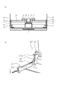
以下、本発明の実施の形態について図面を用いて詳細に説明する。図1は、本発明の第1の実施の形態に係るシート給送装置を備えた画像形成装置の一例であるプリンタの概略構成を示す図である。図1において、100はプリンタ、101は画像形成装置本体であるプリンタ本体、52はプリンタ本体101に設けられ、電子写真方式により画像形成を行う画像形成部、53は画像形成部52にシートSを給送するシート給送装置である。   Hereinafter, embodiments of the present invention will be described in detail with reference to the drawings. FIG. 1 is a diagram illustrating a schematic configuration of a printer that is an example of an image forming apparatus including a sheet feeding device according to a first embodiment of the present invention. In FIG. 1, reference numeral 100 denotes a printer, 101 denotes a printer main body which is an image forming apparatus main body, 52 denotes an image forming unit which is provided in the printer main body 101 and forms an image by an electrophotographic method, and 53 denotes a sheet S to the image forming unit 52. This is a sheet feeding device for feeding.

ここで、画像形成部52はレーザ露光装置5、トナー像を形成する感光体ドラム8、感光体ドラム8に形成されたトナー像をシートSに転写する転写ローラ9などを備えている。なお、7は感光体ドラム8、帯電ローラ7a、現像手段7b等を備えたプロセスカートリッジであり、このプロセスカートリッジ7は、プリンタ本体101に着脱自在に装着されている。   Here, the image forming unit 52 includes a laser exposure device 5, a photosensitive drum 8 that forms a toner image, a transfer roller 9 that transfers the toner image formed on the photosensitive drum 8 to the sheet S, and the like. A process cartridge 7 includes a photosensitive drum 8, a charging roller 7a, a developing unit 7b, and the like. The process cartridge 7 is detachably attached to the printer main body 101.

シート給送装置53は、給送ローラ2と、シート収納部である給紙トレイ1と、給紙トレイ1に昇降可能に設けられ、給紙トレイ1に収納されたシートSを支持して給送ローラ2に押圧するシート支持部材である昇降板22とを備えている。なお、30は後述するように昇降板22が上昇した際、シートSが昇降板22の上方に位置する給送ローラ2に当接する前に、シートSと当接する給送アイドラコロ、16は給送ローラ2等を駆動する駆動モータである。   The sheet feeding device 53 is provided so as to be movable up and down on the feeding roller 2, the sheet feeding tray 1 that is a sheet storage unit, and the sheet S stored in the sheet feeding tray 1. An elevating plate 22 that is a sheet support member that presses against the feed roller 2 is provided. In addition, 30 is a feeding idler roller that comes into contact with the sheet S before the sheet S comes into contact with the feeding roller 2 positioned above the lifting plate 22 when the lifting plate 22 is raised as will be described later. A drive motor for driving the roller 2 and the like.

また、給紙トレイ1のシート給送方向下流側には、給送ローラ2に圧接する分離パッド20が設けられている。そして、このようなシート給送装置53においては、画像形成の際には給送ローラ2により給紙トレイ1からシートSを送り出し、この後、シートSを給送ローラ2に圧接している分離パッド20により1枚ずつ分離するようにしている。   Further, a separation pad 20 that is in pressure contact with the feeding roller 2 is provided on the downstream side of the sheet feeding tray 1 in the sheet feeding direction. In such a sheet feeding device 53, when forming an image, the sheet S is fed from the sheet feeding tray 1 by the feeding roller 2, and then the sheet S is pressed against the feeding roller 2. The pads 20 are separated one by one.

次に、このような構成のプリンタ100における画像形成動作について説明する。画像形成動作が開始されると、まずレーザ露光装置5から画像信号に応じたレーザ光が、表面が帯電処理されると共に、時計回りに回転駆動されている感光体ドラム8に照射される。そして、このような画像信号に応じた光が照射されることにより、感光体ドラム上に潜像が形成される。次に、この感光体ドラム上の潜像は、現像手段7bにより供給されたトナーにより現像され、トナー像として可視化される。   Next, an image forming operation in the printer 100 having such a configuration will be described. When the image forming operation is started, laser light corresponding to the image signal is firstly charged from the laser exposure device 5 to the photosensitive drum 8 that is rotated and rotated clockwise. Then, by irradiating light according to such an image signal, a latent image is formed on the photosensitive drum. Next, the latent image on the photosensitive drum is developed with the toner supplied by the developing means 7b and visualized as a toner image.

また、このトナー画像形成動作に並行して昇降板22が上昇し、給紙トレイ1にセットされたシートSが、給送ローラ2により送り出され、この後、このシートSは分離パッド20によって1枚ずつ分離され、略鉛直に給送される。次に、シートSは、搬送ローラ対3により転写部に搬送される。   In parallel with this toner image forming operation, the elevating plate 22 is raised, and the sheet S set on the sheet feeding tray 1 is sent out by the feeding roller 2. Sheets are separated and fed substantially vertically. Next, the sheet S is conveyed to the transfer unit by the conveying roller pair 3.

そして、この後、可視化された感光体ドラム上のトナー像は転写部において、転写ローラ9に感光体ドラム8に形成されたトナー像と逆極性の電圧を印加することにより、シートSに転写される。次に、トナー像が転写されたシートSは搬送ガイド10によってプリンタ本体上部に配置された定着手段11へと搬送される。そして、この定着手段11を通過する際、シートSに熱及び圧力を加えられることにより、シート上に転写トナー像が定着される。この後、トナー像が定着されたシートSを排出ローラ対12で搬送し、プリンタ本体101の上面に形成した排出部14へと排出する。   After that, the visualized toner image on the photosensitive drum is transferred to the sheet S by applying a voltage having a polarity opposite to that of the toner image formed on the photosensitive drum 8 to the transfer roller 9 in the transfer portion. The Next, the sheet S to which the toner image has been transferred is conveyed by the conveyance guide 10 to the fixing unit 11 disposed at the upper part of the printer main body. When passing through the fixing unit 11, the transfer toner image is fixed on the sheet by applying heat and pressure to the sheet S. Thereafter, the sheet S on which the toner image is fixed is conveyed by the discharge roller pair 12 and discharged to the discharge portion 14 formed on the upper surface of the printer main body 101.

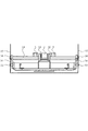
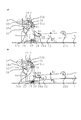
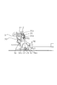
図2は、シート給送装置53の構成を示す図である。図2に示すように、シートが積載される昇降板22は給紙トレイ1に昇降板ボス22aを回動中心として上下方向に回動可能に取り付けられている。また、この昇降板22は、プリンタ本体101と昇降板22の間に設けられた付勢部を構成する圧縮バネである給送バネ23により、矢印R2に示す給送ローラ2の方向の付勢力が与えられている。そして、この給送バネ23により、昇降板22は、シート給送動作が開始されると、積載したシートを給送ローラ2にP1の大きさの圧接圧で押し付けるようになっている。なお、この圧接圧P1は、シート積載量が少なくなった少載でも、シートの給送が可能な大きさに設定されている。   FIG. 2 is a diagram illustrating a configuration of the sheet feeding device 53. As shown in FIG. 2, the lifting plate 22 on which sheets are stacked is attached to the sheet feeding tray 1 so as to be able to rotate in the vertical direction about the lifting plate boss 22 a as a rotation center. Further, the lifting plate 22 is biased in the direction of the feeding roller 2 indicated by an arrow R2 by a feeding spring 23 that is a compression spring constituting a biasing portion provided between the printer main body 101 and the lifting plate 22. Is given. When the sheet feeding operation is started, the elevating plate 22 presses the stacked sheets against the feeding roller 2 with a pressure contact pressure of P1 by the feeding spring 23. Note that the pressure P1 is set to a size that allows the sheet to be fed even when the sheet stacking amount is small.

また、給送ローラ2は、駆動軸24に固定されている。ここで、この駆動軸24は、プリンタ本体101の後述する図4に示すフレームに回転可能に取り付けられている。また、駆動軸24には不図示の駆動列を介して駆動モータ16からの回転駆動力が伝達されるよう構成されている。なお、給送ローラ2は、シートとの摩擦部であるゴム部材が円周上の一定角度間で設けられた、いわゆる半月形状のローラである。さらに、駆動軸24には、後述するリンク部材34の規制を解除する規制解除部材の一例としてのカム部材である給送カム36が固定されている。   The feeding roller 2 is fixed to the drive shaft 24. Here, the drive shaft 24 is rotatably attached to a frame shown in FIG. Further, the drive shaft 24 is configured to transmit a rotational drive force from the drive motor 16 via a drive train (not shown). The feeding roller 2 is a so-called half-moon shaped roller in which a rubber member that is a friction portion with a sheet is provided at a constant angle on the circumference. Further, a feed cam 36 that is a cam member as an example of a restriction releasing member that releases restriction of a link member 34 described later is fixed to the drive shaft 24.

また、昇降板22には、リンク部材ボス34aを回動中心としてリンク部材34が上下方向に回動自在に支持されている。このリンク部材34の回動端には、係合ボス34bが設けられており、この係合ボス34bは、プリンタ本体101の後述する図4に示すフレームに形成された回動規制部としての円弧状の案内部であるリンクガイド穴35と係合している。   Further, the link member 34 is supported on the elevating plate 22 so as to be rotatable in the vertical direction with the link member boss 34a as a rotation center. An engagement boss 34b is provided at the rotation end of the link member 34. The engagement boss 34b is a circle as a rotation restricting portion formed on a frame shown in FIG. It is engaged with a link guide hole 35 that is an arcuate guide.

このリンクガイド穴35は、リンク部材34の移動軌跡を規制する機能を有するものである。そして、リンク部材34は、後述するように、給送カム36が回転すると、この給送カム36の回転に伴って係合ボス34bをリンクガイド穴35に沿って移動させながら上下方向に回動する。なお、本実施の形態において、これら給送カム36、給送バネ23、リンク部材34、リンクガイド穴35により、昇降板22を昇降させる昇降部が構成される。   The link guide hole 35 has a function of regulating the movement trajectory of the link member 34. As will be described later, when the feed cam 36 rotates, the link member 34 rotates in the vertical direction while moving the engagement boss 34b along the link guide hole 35 as the feed cam 36 rotates. To do. In the present embodiment, the feeding cam 36, the feeding spring 23, the link member 34, and the link guide hole 35 constitute an elevating unit that raises and lowers the elevating plate 22.

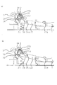
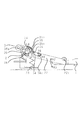
ここで、リンク部材34は、図3に示すように、給紙トレイ1のシート給送方向と直交する幅方向の中央に設けられている給送ローラ2を中心として、給紙トレイ1の外側に略対称に配置されている。そして、給送カム36は、図4に示すように、リンク部材34の回動端と係合している。なお、このように配置にすることにより、フレーム40間のスパンを小型化するように構成されている。つまり、本構成ではフレーム40間のスパンは、シートセットに必要な給紙トレイ1のスパンと、その外側にある昇降部のスパンとの合計となる。そして、昇降部の構成要素である給送カム36、リンク部材34及びリンク部材34の昇降板22上の回動支点を同一平面上に設けることにより、昇降部のスパンを小型化している。   Here, as shown in FIG. 3, the link member 34 is formed on the outer side of the paper feed tray 1 around the feed roller 2 provided at the center in the width direction orthogonal to the sheet feed direction of the paper feed tray 1. Are arranged approximately symmetrically. The feeding cam 36 is engaged with the rotating end of the link member 34 as shown in FIG. Note that the arrangement between the frames 40 is reduced in size by arranging in this way. In other words, in this configuration, the span between the frames 40 is the sum of the span of the paper feed tray 1 necessary for sheet setting and the span of the elevating unit outside the span. And the span of the raising / lowering part is miniaturized by providing on the same plane the feeding cam 36 which is a component of the raising / lowering part, the link member 34, and the rotation fulcrum on the raising / lowering plate 22 of the link member 34.

ところで、図5は、リンクガイド穴35の形状を示した図である。リンクガイド穴35は、保持部35a(クロスハッチング部)と、係合ボス34bの移動をガイドするガイド部35b(斜線部)とから構成されている。ここで、保持部35aは、リンク部材34の回動端側に設けられた係合ボス34bを係止することにより、昇降板22を介して給送バネ23からの付勢力を受けるリンク部材34を初期位置となる待機位置に保持するものである。   FIG. 5 is a view showing the shape of the link guide hole 35. The link guide hole 35 includes a holding portion 35a (cross hatched portion) and a guide portion 35b (shaded portion) that guides the movement of the engaging boss 34b. Here, the holding portion 35 a is a link member 34 that receives an urging force from the feeding spring 23 via the lifting plate 22 by locking an engagement boss 34 b provided on the rotation end side of the link member 34. Is held at a standby position as an initial position.

そして、この保持部35aに係合ボス34bを係止してリンク部材34を待機位置に保持することにより、給送バネ23からの付勢力を受けても昇降板22は上方に移動することない。つまり、リンクガイド穴35の保持部35aは、昇降板22の上方移動を規制するストッパの機能を有する。   Then, by engaging the engaging boss 34b with the holding portion 35a and holding the link member 34 at the standby position, the elevating plate 22 does not move upward even when the urging force from the feeding spring 23 is received. . That is, the holding portion 35 a of the link guide hole 35 has a stopper function that restricts the upward movement of the elevating plate 22.

ガイド部35bは、給送バネ23からの付勢力により給送カム36のカム面36aに沿って移動する係合ボス34bを案内する案内通路を構成するものであり、リンク部材34は、このガイド部35bに沿って係合ボス34bを移動させながら、上下方向に移動する。そして、このように給送カム36の動作と連動するリンク部材34の上下方向の移動に伴って昇降板22が上下方向に回動(移動)する。つまり、リンクガイド穴35のガイド部35bは、昇降板22の上下方向の回動を案内するガイド機能を有する。   The guide portion 35b constitutes a guide passage that guides the engaging boss 34b that moves along the cam surface 36a of the feeding cam 36 by the urging force from the feeding spring 23, and the link member 34 is formed by this guide. While moving the engagement boss 34b along the portion 35b, the engagement boss 34b moves in the vertical direction. As the link member 34 moves in the vertical direction in conjunction with the operation of the feeding cam 36 in this way, the elevating plate 22 rotates (moves) in the vertical direction. That is, the guide portion 35 b of the link guide hole 35 has a guide function for guiding the vertical movement of the elevating plate 22.

なお、既述した図2において、矢印R1は駆動軸24を中心に回転する方向であり、駆動軸24、給送ローラ2、給送カム36は矢印R1に示す方向に回転する。矢印R2、R3は、昇降板22が昇降板ボス22aを中心に回転する方向、矢印R4、R5は、リンク部材34がリンクガイド穴35に沿って回動する方向、矢印R8、R9は、リンク部材34がリンク部材ボス34aを中心に回動する方向である。   In FIG. 2 described above, the arrow R1 is the direction of rotation about the drive shaft 24, and the drive shaft 24, the feed roller 2, and the feed cam 36 rotate in the direction indicated by the arrow R1. Arrows R2 and R3 are directions in which the lifting plate 22 rotates about the lifting plate boss 22a, arrows R4 and R5 are directions in which the link member 34 rotates along the link guide hole 35, and arrows R8 and R9 are links. This is the direction in which the member 34 rotates around the link member boss 34a.

ここで、係合ボス34bを係止してリンク部材34の移動を規制する係止部である保持部35aは、ガイド部35bの下端に設けられている。また、保持部35aにより係合ボス34bが係止されたリンク部材34は、給送カム36が矢印R1の方向に1回転する度に、給送カム36により回動端が押圧されてガイド部側に移動し、係止が解除される。そして、このようにリンク部材34の係止が解除されることにより、この後、リンク部材34は給送バネ23の付勢力により、ガイド部35bに沿って矢印R4,R5に移動する。また、昇降板22は、このようにリンク部材34を移動させながら矢印R2,R3に示す方向に1往復の回動運動を行う。   Here, the holding portion 35a, which is a locking portion that locks the engagement boss 34b and restricts the movement of the link member 34, is provided at the lower end of the guide portion 35b. In addition, the link member 34 whose engaging boss 34b is locked by the holding portion 35a has its rotating end pressed by the feed cam 36 every time the feed cam 36 makes one rotation in the direction of the arrow R1, and the guide portion. Moves to the side and the lock is released. Then, when the locking of the link member 34 is released in this way, the link member 34 is moved to the arrows R4 and R5 along the guide portion 35b by the urging force of the feeding spring 23 thereafter. Further, the elevating plate 22 performs a reciprocating rotational movement in the directions indicated by the arrows R2 and R3 while moving the link member 34 in this manner.

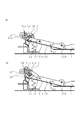
次に、このような構成のシート給送装置53のシート給送動作について説明する。シートの給送動作が開始されるまでは、図6の(a)に示すように、給送ローラ2、給送カム36、リンク部材34、昇降板22は給送初期位置にある。なお、この給送ローラ2、給送カム36、リンク部材34、昇降板22は、給送動作1回毎に、この給送初期位置に戻るように構成されている。   Next, the sheet feeding operation of the sheet feeding device 53 having such a configuration will be described. Until the sheet feeding operation is started, the feeding roller 2, the feeding cam 36, the link member 34, and the elevating plate 22 are in the feeding initial position as shown in FIG. The feeding roller 2, the feeding cam 36, the link member 34, and the elevating plate 22 are configured to return to the feeding initial position every feeding operation.

次に、シート給送動作が開始されると、まず不図示のソレノイドが吸引され、不図示の駆動列を介して駆動モータ16から駆動軸24に矢印R1方向の回転駆動力が伝達され、駆動軸24が回転を開始する。これに伴い、駆動軸24に固定された給送ローラ2と一体に給送カム36が矢印R1方向に回転を開始する。   Next, when the sheet feeding operation is started, a solenoid (not shown) is first sucked, and a rotational driving force in the direction of arrow R1 is transmitted from the drive motor 16 to the drive shaft 24 via a drive train (not shown). The shaft 24 starts to rotate. Accordingly, the feeding cam 36 starts to rotate in the direction of the arrow R1 integrally with the feeding roller 2 fixed to the drive shaft 24.

そして、給送カム36が回転することにより、昇降板22に回動自在に支持されているリンク部材34の回動端が給送カム36により押圧され、図6の(b)に示すように、リンク部材34の係合ボス34bが保持部35aからガイド部35bに移動する。これにより、係合ボス34bは矢印R4の方向に移動可能となり、このようにリンク部材34が移動可能となることにより、昇降板22は給送バネ23の付勢力を受け、図7の(a)に示すように、矢印R2に示す給送ローラ2の方向、すなわち上方に回動を開始する。   Then, as the feed cam 36 rotates, the turning end of the link member 34 rotatably supported by the elevating plate 22 is pressed by the feed cam 36, as shown in FIG. 6B. The engaging boss 34b of the link member 34 moves from the holding portion 35a to the guide portion 35b. As a result, the engagement boss 34b can move in the direction of the arrow R4, and the link member 34 can move in this way, whereby the elevating plate 22 receives the urging force of the feeding spring 23, and the (a) of FIG. ), The feed roller 2 starts to rotate in the direction indicated by the arrow R2, that is, upward.

この後、昇降板22上に積載されているシートの最上位のシートが給送アイドラコロ30に当接すると、昇降板22は上方回動を停止し、これに伴いリンク部材34は矢印R4の方向への移動を停止する。そして、このように昇降板22が停止した後、最上位のシートに駆動軸24と共に回転する半月状の給送ローラ2が図7の(b)に示す位置で当接し、これにより最上位のシートが送り出される。   Thereafter, when the uppermost sheet of the sheets stacked on the elevating plate 22 comes into contact with the feeding idler roller 30, the elevating plate 22 stops rotating upward, and accordingly, the link member 34 moves in the direction of the arrow R4. Stop moving to. After the elevating plate 22 stops in this way, the half-moon-shaped feeding roller 2 that rotates together with the drive shaft 24 comes into contact with the uppermost sheet at the position shown in FIG. The sheet is sent out.

次に、シートの送り出しが開始された後、給送ローラ2と共に給送カム36がさらに回転すると、給送カム36は、図8に示すように移動を停止しているリンク部材34の回動端と再度係合してリンク部材34を押圧する。これにより、リンク部材34は、係合ボス34bをガイド部35bに沿って矢印R5の方向へ移動させながら、下方回動を開始する。そして、このようにシート給送後、給送カム36により押圧されながらリンク部材34が下方回動を開始すると、給送カム36による駆動力はリンク部材34を介して昇降板22へ伝達され、昇降板22は矢印R3の方向、すなわち下方回動を開始する。   Next, after the feeding of the sheet is started, when the feeding cam 36 further rotates together with the feeding roller 2, the feeding cam 36 rotates the link member 34 that has stopped moving as shown in FIG. The link member 34 is pressed again by engaging with the end. Thereby, the link member 34 starts to rotate downward while moving the engaging boss 34b along the guide portion 35b in the direction of the arrow R5. Then, after the sheet is fed in this way, when the link member 34 starts to rotate downward while being pressed by the feeding cam 36, the driving force by the feeding cam 36 is transmitted to the lift plate 22 via the link member 34, The lift plate 22 starts to rotate in the direction of arrow R3, that is, downward.

次に、駆動軸24が初期位置に戻った時点で、駆動モータ16から駆動軸24への回転駆動力は絶たれ、給送ローラ2、給送カム36は、既述した図6の(a)に示す給送初期位置で回転を停止する。なお、このように給送カム36が給送初期位置に達すると、給送カム36による押圧が解除されてリンク部材34は、図6の(a)に示すR9の方向に回動し、リンク部材34の係合ボス34bがガイド部35bから保持部35aに移動する。これより、リンク部材34、昇降板22も給送初期位置に戻り、この後、移動を停止する。そして、このような動作を繰り返し行うことにより、給紙トレイ1に積載されたシートは、給送ローラ2の1回転毎に、1枚ずつ分離給送される。   Next, when the drive shaft 24 returns to the initial position, the rotational driving force from the drive motor 16 to the drive shaft 24 is cut off, and the feed roller 2 and the feed cam 36 are shown in FIG. ) Stops rotation at the initial feed position shown in (). When the feeding cam 36 reaches the feeding initial position in this way, the pressing by the feeding cam 36 is released, and the link member 34 rotates in the direction of R9 shown in FIG. The engaging boss 34b of the member 34 moves from the guide part 35b to the holding part 35a. As a result, the link member 34 and the lifting plate 22 also return to the feeding initial position, and then stop moving. By repeating such an operation, the sheets stacked on the sheet feeding tray 1 are separated and fed one by one for each rotation of the feeding roller 2.

ここで、本実施の形態において、給送動作、1回毎に昇降板22は給送初期位置に戻るため、プリント終了時にはシートと給送アイドラコロ30は常に離間しており、ユーザが容易にシートを積載することができる。また、給送カム36のプロファイル、及びリンクガイド穴35のプロファイルの選択により、昇降板22の矢印R2及び矢印R3方向への回転速度を決定できる。   Here, in the present embodiment, since the lifting plate 22 returns to the initial feeding position for each feeding operation, the sheet and the feeding idler roller 30 are always separated from each other at the end of printing. Can be loaded. Further, by selecting the profile of the feeding cam 36 and the profile of the link guide hole 35, the rotational speed of the elevating plate 22 in the directions of the arrows R2 and R3 can be determined.

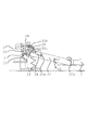
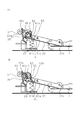
ところで、図9の(a)は、本実施の形態に係る昇降板22の上死点22uと下死点22dを重ねて描いた図である。なお、図9の(b)は、従来の昇降板22の上死点22uと下死点22dを重ねて描いた図である。ここで、図9の(a)及び(b)に示すように、昇降板22の上死点22uと下死点22dとの回動角度θは同一角度である。   Incidentally, FIG. 9A is a diagram in which the top dead center 22u and the bottom dead center 22d of the elevating plate 22 according to the present embodiment are overlapped. FIG. 9B is a diagram in which the top dead center 22u and the bottom dead center 22d of the conventional lift plate 22 are drawn to overlap each other. Here, as shown in FIGS. 9A and 9B, the rotation angle θ of the top dead center 22u and the bottom dead center 22d of the lifting plate 22 is the same angle.

また、図9の(a)に示すハッチング部は、給送カム36の回転軌跡を、図9の(b)に示すハッチング部は、給送カム21の回転軌跡を示している。なお、図9の(a)に示すD1は、本実施の形態に係る給送カム36の最大回転半径φであり、図9の(b)に示すD2は従来の給送カム21の最大回転半径φである。そして、この図9の(a)及び(b)から明らかなように、給送カム21の最大回転半径φは、従来のD2からD1に、ほぼ半減している。   Further, the hatching portion shown in FIG. 9A shows the rotation locus of the feeding cam 36, and the hatching portion shown in FIG. 9B shows the rotation locus of the feeding cam 21. 9A is the maximum rotation radius φ of the feeding cam 36 according to the present embodiment, and D2 shown in FIG. 9B is the maximum rotation of the conventional feeding cam 21. Radius φ. As is apparent from FIGS. 9A and 9B, the maximum turning radius φ of the feeding cam 21 is substantially halved from the conventional D2 to D1.

このように、本実施の形態では、昇降板22にリンク部材34を回動自在に支持し、シートを給送する際、給送カム36により、移動が規制されているリンク部材34のガイド部35bに沿った移動が可能となるようにしている。これにより、昇降板22の回動角度θを同一に保ちながら、すなわち積載可能なシート高さを犠牲にすることなく、給送カムの最大回転半径を小さくすることができる。   As described above, in the present embodiment, the link member 34 is rotatably supported by the elevating plate 22 and when the sheet is fed, the guide portion of the link member 34 whose movement is restricted by the feeding cam 36. Movement along the line 35b is made possible. Thus, the maximum rotation radius of the feeding cam can be reduced while keeping the rotation angle θ of the elevating plate 22 the same, that is, without sacrificing the stackable sheet height.

つまり、本実施の形態では、昇降板22の回動角度が同一の条件において、従来構成と比較して、給送カム36の最大回転半径を大幅に小さくすることができる。この結果、小型の給送カム36でもシートの積載可能枚数を増やすことができる。さらに、給送カム36と、その周辺部品との間に空間が形成され、この空間を詰めることにより、リンク部材34を用いた場合でも、より小型な画像形成装置のシート給送装置を提供することができる。また、同サイズの画像形成装置であれば、本構成ではカートリッジサイズを大きくすることができ、さらに大容量のトナーカートリッジを装着することができる画像形成装置を提供することができる。   That is, in the present embodiment, the maximum turning radius of the feeding cam 36 can be significantly reduced as compared with the conventional configuration under the same rotation angle of the elevating plate 22. As a result, the number of sheets that can be stacked can be increased even with the small feeding cam 36. Further, a space is formed between the feeding cam 36 and its peripheral parts, and by filling this space, a smaller sheet feeding device of the image forming apparatus can be provided even when the link member 34 is used. be able to. In addition, if the image forming apparatus has the same size, this configuration can increase the cartridge size, and can provide an image forming apparatus in which a large capacity toner cartridge can be mounted.

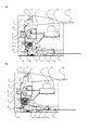
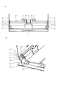
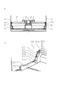
次に、本発明の第2の実施の形態について説明する。図10は、本実施の形態に係るシート給送装置の構成を説明する図である。なお、図10において、既述した図2と同一符号は、同一又は相当部分を示している。   Next, a second embodiment of the present invention will be described. FIG. 10 is a diagram illustrating the configuration of the sheet feeding apparatus according to the present embodiment. 10, the same reference numerals as those in FIG. 2 described above indicate the same or corresponding parts.

図10において、38は給送カムであり、この給送カム38のカム面には突起部38aが設けられている。ここで、図11に示すように、この突起部38aは、給送カム38のカム面に高さHで突設されている。なお、図11において、Gはリンクガイド穴35と係合ボス34bの間のギャップを示している。そして、本実施の形態において、この突起部38aの高さHと、リンクガイド穴35と係合ボス34bの間のギャップGは、H<Gとなるように構成されている。   In FIG. 10, reference numeral 38 denotes a feeding cam, and a protrusion 38 a is provided on the cam surface of the feeding cam 38. Here, as shown in FIG. 11, the protruding portion 38 a protrudes from the cam surface of the feeding cam 38 at a height H. In FIG. 11, G indicates a gap between the link guide hole 35 and the engagement boss 34b. In the present embodiment, the height H of the protrusion 38a and the gap G between the link guide hole 35 and the engagement boss 34b are configured such that H <G.

また図10に示すように、リンク部材34と昇降板22の間には、リンク部材付勢部材として、リンクバネ39が設けられている。ここで、このリンクバネ39はねじりコイルバネであり、一端がリンク部材34に他端が昇降板22に係止されている。そして、このリンクバネ39により、リンク部材34は昇降板22に対して、矢印R9に示すリンク部材34を下方に回動させる方向に付勢されている。   As shown in FIG. 10, a link spring 39 is provided between the link member 34 and the elevating plate 22 as a link member urging member. Here, the link spring 39 is a torsion coil spring, and one end is locked to the link member 34 and the other end is locked to the elevating plate 22. Then, the link member 34 is urged by the link spring 39 in the direction of rotating the link member 34 indicated by the arrow R9 downward with respect to the lifting plate 22.

また、本実施の形態において、昇降板22を給送ローラ2の方向に常時付勢する付勢部材である給送バネ23のバネ力は、既述した第1の実施の形態の、昇降板22を給送ローラ2の方向に常時付勢する給送バネ23のバネ力と比較して小さく設定されている。具体的には、給送バネ23により、昇降板22と給送ローラ2とが圧接するときに発生する圧接力をP2とすると、P2は、P1>P2>0となるように構成されている。なお、P1は、既述した第1の実施の形態に係る給送バネ23による圧接圧である。またP2>0とした意味は、シート積載量が満載の場合においてシート最上面紙が給送ローラと接するための十分条件であるためである。   Further, in the present embodiment, the spring force of the feeding spring 23 that is a biasing member that constantly biases the lifting plate 22 in the direction of the feeding roller 2 is the lifting plate of the first embodiment described above. 22 is set smaller than the spring force of the feed spring 23 that constantly biases the feed roller 2 in the direction of the feed roller 2. Specifically, P2 is configured such that P1> P2> 0, where P2 is a pressing force generated when the lifting plate 22 and the feeding roller 2 are pressed against each other by the feeding spring 23. . Note that P1 is a pressure contact pressure by the feeding spring 23 according to the first embodiment described above. Further, the meaning of P2> 0 is that it is a sufficient condition for the uppermost sheet of the sheet to come into contact with the feeding roller when the sheet stacking amount is full.

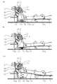
次に、このような構成のシート給送装置53のシート給送動作について説明する。シートの給送動作が開始されるまでは、図10の(a)に示すように、給送ローラ2、給送カム38、リンク部材34、昇降板22は給送初期位置にある。なお、この給送ローラ2、給送カム38、リンク部材34、昇降板22は、給送動作1回毎に、この給送初期位置に戻るように構成されている。   Next, the sheet feeding operation of the sheet feeding device 53 having such a configuration will be described. Until the sheet feeding operation is started, as shown in FIG. 10A, the feeding roller 2, the feeding cam 38, the link member 34, and the lifting plate 22 are in the feeding initial position. The feeding roller 2, the feeding cam 38, the link member 34, and the elevating plate 22 are configured to return to the feeding initial position every feeding operation.

次に、シート給送動作が開始されると、駆動軸24が回転を開始し、これに伴い、駆動軸24に固定された給送ローラ2、給送カム38が矢印R1の方向に回転を開始する。そして、給送カム38が回転することにより、昇降板22に回動自在に支持されているリンク部材34の回動端が給送カム36により押圧され、図10の(b)に示すように、リンク部材34の係合ボス34bが保持部35aからガイド部35bに移動する。   Next, when the sheet feeding operation is started, the driving shaft 24 starts to rotate, and accordingly, the feeding roller 2 and the feeding cam 38 fixed to the driving shaft 24 rotate in the direction of the arrow R1. Start. Then, as the feed cam 38 rotates, the turning end of the link member 34 rotatably supported by the elevating plate 22 is pressed by the feed cam 36, as shown in FIG. The engaging boss 34b of the link member 34 moves from the holding portion 35a to the guide portion 35b.

これにより、係合ボス34bは矢印R4の方向に移動可能となる。そして、このようにリンク部材34が移動可能となることにより、昇降板22は給送バネ23の付勢力を受け、図12の(a)に示すように、矢印R2に示す給送ローラ2の方向、すなわち上方に回動を開始する。   Thereby, the engagement boss 34b can move in the direction of the arrow R4. When the link member 34 is movable in this manner, the elevating plate 22 receives the urging force of the feeding spring 23, and as shown in FIG. 12 (a), the feeding roller 2 indicated by the arrow R2 is moved. The rotation starts in the direction, that is, upward.

この後、昇降板22上に積載されているシートの最上位のシートが給送アイドラコロ30に当接すると、昇降板22は上方回動を停止し、これに伴いリンク部材34は矢印R4の方向への移動を停止する。そして、このように昇降板22が停止した後、最上位のシートに駆動軸24と共に回転する半月状の給送ローラ2が図12の(b)に示す位置で当接し、これにより最上位のシートが送り出される。   Thereafter, when the uppermost sheet of the sheets stacked on the elevating plate 22 comes into contact with the feeding idler roller 30, the elevating plate 22 stops rotating upward, and accordingly, the link member 34 moves in the direction of the arrow R4. Stop moving to. After the elevating plate 22 stops in this way, the half-moon-shaped feeding roller 2 that rotates together with the drive shaft 24 contacts the uppermost sheet at the position shown in FIG. The sheet is sent out.

次に、シートの送り出しが開始された後、給送ローラ2と共に給送カム38がさらに回転すると、給送カム38は、移動を停止しているリンク部材34の回動端と再度係合してリンク部材34を押圧する。これにより、リンク部材34は、係合ボス34bをガイド部35bに沿って矢印R5の方向へ移動させながら、下方回動を開始する(図8参照)。そして、このように給送カム38により押圧されながらリンク部材34が下方回動を開始すると、給送カム38による駆動力はリンク部材34を介して昇降板22へ伝達され、昇降板22は矢印R3の方向、すなわち下方回動を開始する。   Next, after the feeding of the sheet is started, when the feeding cam 38 further rotates together with the feeding roller 2, the feeding cam 38 is engaged again with the rotating end of the link member 34 that has stopped moving. Then, the link member 34 is pressed. As a result, the link member 34 starts to rotate downward while moving the engagement boss 34b in the direction of the arrow R5 along the guide portion 35b (see FIG. 8). When the link member 34 starts to rotate downward while being pressed by the feed cam 38 in this way, the driving force by the feed cam 38 is transmitted to the lift plate 22 via the link member 34, and the lift plate 22 is The direction of R3, that is, downward rotation is started.

次に、駆動軸24が初期位置に戻った時点で、駆動モータ16から駆動軸24への回転駆動力は絶たれ、給送ローラ2、給送カム36は、既述した図10の(a)に示す給送初期位置で回転を停止する。なお、このように給送カム36が給送初期位置に達すると、給送カム36による押圧が解除されてリンク部材34は、図10の(a)に示すR9の方向に回動し、リンク部材34の係合ボス34bがガイド部35bから保持部35aに移動する。これより、リンク部材34、昇降板22も給送初期位置に戻り、この後、移動を停止する。そして、このような動作を繰り返し行うことにより、給紙トレイ1に積載されたシートは、給送ローラ2の1回転毎に、1枚ずつ分離給送される。   Next, when the drive shaft 24 returns to the initial position, the rotational driving force from the drive motor 16 to the drive shaft 24 is cut off, and the feed roller 2 and the feed cam 36 are shown in FIG. ) Stops rotation at the initial feed position shown in (). When the feeding cam 36 reaches the feeding initial position in this way, the pressing by the feeding cam 36 is released, and the link member 34 rotates in the direction of R9 shown in FIG. The engaging boss 34b of the member 34 moves from the guide part 35b to the holding part 35a. As a result, the link member 34 and the lifting plate 22 also return to the feeding initial position, and then stop moving. By repeating such an operation, the sheets stacked on the sheet feeding tray 1 are separated and fed one by one for each rotation of the feeding roller 2.

ところで、本実施の形態において、シート積載量が少載時において、図13に示すように、給送ローラ2が昇降板22に積載された最上位シートと当接するタイミングで、給送カム38の突起部38aがリンク部材34を押圧するようになっている。そして、このように突起部38aがリンク部材34を押圧すると、リンク部材34はリンク部材ボス34aを中心に、矢印R8の方向に回動する。   By the way, in the present embodiment, when the sheet stacking amount is small, as shown in FIG. 13, at the timing when the feeding roller 2 contacts the uppermost sheet stacked on the lifting plate 22, The protrusion 38 a presses the link member 34. When the projection 38a presses the link member 34 in this way, the link member 34 rotates in the direction of the arrow R8 about the link member boss 34a.

ここで、リンクガイド穴35と係合ボス34bの間のギャップGと突起高さHは、既述したようにH<Gの関係を満たすように構成されている。このため、このように突起部38aにより押圧されて矢印R8の方向に回動したリンク部材34は、リンクガイド穴35と干渉することはなく、矢印R8の方向に回動可能である。そして、このようにリンク部材34が回動すると、リンク部材34と昇降板22の間にはリンクバネ39のバネ力により、昇降板22を矢印R2に示す給送ローラ方向の付勢力が発生する。   Here, the gap G and the projection height H between the link guide hole 35 and the engagement boss 34b are configured to satisfy the relationship of H <G as described above. Therefore, the link member 34 that is pressed by the protrusion 38a and rotated in the direction of the arrow R8 in this manner does not interfere with the link guide hole 35 and can rotate in the direction of the arrow R8. When the link member 34 rotates in this way, a biasing force in the direction of the feeding roller indicated by the arrow R2 is generated between the link member 34 and the lift plate 22 by the spring force of the link spring 39. .

これにより、シート積載量が少載時において、昇降板22と給送ローラ2の圧接圧を強くすることができる。つまり、リンクバネ39と給送カム38の突起部38aとにより構成される補助付勢部により、シートを給送する際に昇降板22を給送ローラ2の方向に付勢する付勢力を発生している。これにより、シート給送時、昇降板22と給送ローラ2の圧接圧を強くすることができる。   Thereby, when the sheet stacking amount is small, the pressure contact pressure between the lifting plate 22 and the feeding roller 2 can be increased. In other words, an urging force that urges the elevating plate 22 in the direction of the feeding roller 2 when the sheet is fed is generated by the auxiliary urging unit configured by the link spring 39 and the protrusion 38 a of the feeding cam 38. is doing. Thereby, the pressure contact pressure between the lifting plate 22 and the feeding roller 2 can be increased during sheet feeding.

このとき増加する圧接圧をP3とすると、P1=P2+P3となるように、給送バネ23、リンクバネ39及び突起高さHが設定されている。ここで、本実施の形態のように、給送バネ23の他にリンクバネ39を設け、シートを給送する際、このリンクバネ39と給送バネ23とにより、P1を確保するようにすることにより、給送バネ23の付勢力を弱くすることができる。なお、この給送バネ23の付勢力は、給送性能から決定されており、給送バネ23の付勢力が大きいほど給送性能は高まる。   When the pressure contact pressure increasing at this time is P3, the feeding spring 23, the link spring 39, and the projection height H are set so that P1 = P2 + P3. Here, as in the present embodiment, a link spring 39 is provided in addition to the feeding spring 23, and when the sheet is fed, P1 is secured by the link spring 39 and the feeding spring 23. Thus, the urging force of the feeding spring 23 can be weakened. The urging force of the feeding spring 23 is determined from the feeding performance, and the feeding performance increases as the urging force of the feeding spring 23 increases.

このため、既述した第1の実施の形態のように、給送バネ23だけ圧接圧を確保する場合には、給送バネ23の付勢力が大きくなり、このように付勢力が大きくなると、昇降板22に積載されたシートと給送アイドラコロ30とが当接する際の当接音が大きくなる。これに対し、本実施の形態のように、リンクバネ39と給送バネ23とにより、P1を確保するようにした場合、給送バネ23の付勢力を弱くすることができ、これに伴い当接音を低減することができる。   For this reason, when the pressure contact pressure is ensured only by the feeding spring 23 as in the first embodiment described above, the urging force of the feeding spring 23 is increased. The contact sound when the sheet loaded on the lifting plate 22 and the feeding idler roller 30 come into contact with each other increases. On the other hand, when P1 is secured by the link spring 39 and the feeding spring 23 as in the present embodiment, the urging force of the feeding spring 23 can be weakened. Contact sound can be reduced.

つまり、本実施の形態においては、給送アイドラコロ30と昇降板22、または昇降板22に積載されたシートとが当接した後に、給送カム38の突起部38aがリンク部材34を押圧するようにしている。これにより、昇降板22に矢印R2の方向の付勢力が発生するため、給送アイドラコロ30と昇降板22またはシートの当接後に、昇降板22と給送ローラ2の付勢力を再加圧することができる。   That is, in the present embodiment, the protrusion 38 a of the feeding cam 38 presses the link member 34 after the feeding idler roller 30 and the lifting plate 22 or the sheet loaded on the lifting plate 22 abut. I have to. As a result, an urging force in the direction of the arrow R2 is generated on the elevating plate 22, so that the urging force of the elevating plate 22 and the feeding roller 2 is re-pressurized after the feeding idler roller 30 and the elevating plate 22 or the sheet abut. Can do.

これを給送ローラ2と昇降板22の圧接圧の観点から説明すると、給送バネ23による給送ローラ2と昇降板22の圧接圧は、既述した第1の実施の形態では給送性能を満たす接圧としてP1としている。一方、本実施の形態では、給送バネ23による給送ローラ2と昇降板22の接圧P2を、P1より小さい値としている。これにより、当接音を低減することができる。   This will be described from the viewpoint of the pressure contact pressure between the feed roller 2 and the lift plate 22. The pressure contact pressure between the feed roller 2 and the lift plate 22 by the feed spring 23 is the feed performance in the first embodiment described above. P1 is set as the contact pressure satisfying the above. On the other hand, in the present embodiment, the contact pressure P2 between the feeding roller 2 and the lifting plate 22 by the feeding spring 23 is set to a value smaller than P1. Thereby, a contact sound can be reduced.

しかしながら式2より、P1>P2のため、給送バネ23のみでは給送性能が低下してしまう。それを補うため、リンクバネ39及び給送カム38の突起部38aにより再加圧し、P3の圧接圧を発生させており、これによりP1>P2により不足する接圧を補い、十分な給送性能を確保することができる。   However, from Formula 2, since P1> P2, the feeding performance is lowered only by the feeding spring 23. In order to compensate for this, pressure is re-pressurized by the link spring 39 and the projection 38a of the feeding cam 38 to generate a pressure contact pressure of P3, thereby compensating for the insufficient contact pressure by P1> P2, and sufficient feeding performance. Can be secured.

以上説明したように、本実施の形態のように、リンク部材34が回動したときにリンクバネ39及び給送カム38の突起部38aにより昇降板22を付勢することにより、より小型かつ低騒音な画像形成装置のシート給送装置を提供することができる。   As described above, as in the present embodiment, when the link member 34 is rotated, the lifting plate 22 is urged by the link spring 39 and the protrusion 38a of the feeding cam 38, thereby reducing the size and the size of the lift plate 22. A sheet feeding device for a noisy image forming apparatus can be provided.

なお、これまで説明した第1及び第2の実施の形態においては、リンクガイド穴35をフレームに形成するようにしたが、リンク先端の軌跡を規制する機能を有する部材ならば、他の部材にリンクガイド穴35を形成しても良い。また、リンク部材ボス34aの位置を、昇降板22の特定の点としているが、昇降板22上であれば、他の場所であっても同様に好適である。この場合、リンク部材ボス34aの位置の選択により、給送カム36の最大回転半径を決定することができる。   In the first and second embodiments described so far, the link guide hole 35 is formed in the frame. However, if the member has a function of regulating the locus of the link tip, other members may be used. A link guide hole 35 may be formed. Moreover, although the position of the link member boss 34a is a specific point of the elevating plate 22, as long as it is on the elevating plate 22, it is also suitable in other places. In this case, the maximum rotation radius of the feeding cam 36 can be determined by selecting the position of the link member boss 34a.

また、昇降板22の回動角度θを同一条件とし、給送カムの最大回転半径を小さくする構成としたが、逆に給送カムの最大回転半径を同一条件とする構成も同様に好適である。この場合、リンク部材34を設けることにより、昇降板22の回動角度θを大きくすることができ、シート積載量がより大きいシート給送装置を提供することができる。また、穴をリンク部材に設け、ボスをフレームに設けるようにしても良い。   Further, although the rotation angle θ of the lifting plate 22 is set to the same condition and the maximum rotation radius of the feeding cam is reduced, a configuration where the maximum rotation radius of the feeding cam is set to the same condition is also suitable. is there. In this case, by providing the link member 34, the rotation angle θ of the elevating plate 22 can be increased, and a sheet feeding apparatus having a larger sheet stacking amount can be provided. Moreover, a hole may be provided in the link member and a boss may be provided in the frame.

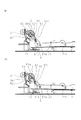
次に、本発明の第3の実施の形態について説明する。図14は、本実施の形態に係るシート給送装置の構成を説明する図である。なお、図14において、既述した図2と同一符号は、同一又は相当部分を示している。   Next, a third embodiment of the present invention will be described. FIG. 14 is a diagram illustrating the configuration of the sheet feeding apparatus according to the present embodiment. In FIG. 14, the same reference numerals as those in FIG. 2 described above indicate the same or corresponding parts.

図14において、70はリンク部材であり、このリンク部材70は、リンク部材ボス70aを中心として、昇降板22に回動自在に支持されている。71は回動規制部であるガイド部材であり、このガイド部材71は駆動軸24を中心に矢印R1方向及びその反対方向に回動自在に設けられている。ここで、ガイド部材71には、長溝を構成するガイド部材穴71aが設けられており、このガイド部材穴71aに、リンク部材70の回動端に設けられたボス70bを係合させることにより、リンク部材70の移動が規制される。72はガイド部材ストッパであり、このガイド部材ストッパ72はフレームに設けられ、ガイド部材71の回転角度を規制する。そして、これら駆動軸24、給送カム36、リンク部材70、ガイド部材71、ガイド部材ストッパ72により、昇降板22を昇降させる昇降部が構成される。   In FIG. 14, reference numeral 70 denotes a link member, and this link member 70 is rotatably supported by the elevating plate 22 around a link member boss 70a. Reference numeral 71 denotes a guide member which is a rotation restricting portion. The guide member 71 is provided so as to be rotatable about the drive shaft 24 in the direction of arrow R1 and in the opposite direction. Here, the guide member 71 is provided with a guide member hole 71a constituting a long groove, and by engaging the boss 70b provided at the rotation end of the link member 70 with this guide member hole 71a, The movement of the link member 70 is restricted. Reference numeral 72 denotes a guide member stopper, and the guide member stopper 72 is provided on the frame and regulates the rotation angle of the guide member 71. The drive shaft 24, the feeding cam 36, the link member 70, the guide member 71, and the guide member stopper 72 constitute an elevating unit that raises and lowers the elevating plate 22.

なお、図15の(a)及び(b)に示すように、給送カム36、リンク部材70、ガイド部材71、ガイド部材ストッパ72は、給送ローラ2を中心として、略対象に配置されている。また、リンク部材70は、給紙トレイ1の外側に設けられており、給送カム36はリンク部材70と係合する位置に設けられている。ガイド部材71はリンク部材70とフレーム40の間に、駆動軸24に回動自在に設けられ、ガイド部材ストッパ72はフレーム40に固定された円柱状のボスとして、ガイド部材71と接触する位置に設けられている。   As shown in FIGS. 15A and 15B, the feeding cam 36, the link member 70, the guide member 71, and the guide member stopper 72 are arranged substantially on the object with the feeding roller 2 as the center. Yes. Further, the link member 70 is provided outside the paper feed tray 1, and the feeding cam 36 is provided at a position where it is engaged with the link member 70. The guide member 71 is rotatably provided on the drive shaft 24 between the link member 70 and the frame 40, and the guide member stopper 72 is a columnar boss fixed to the frame 40 at a position in contact with the guide member 71. Is provided.

そして、このように構成することにより、給送カム36が矢印R1方向に1回転する度に、昇降板22が、図14に示す矢印R2及び矢印R3の方向に1往復する。即ち、給送カム36が回転すると、リンク部材70を介して、昇降板22の位置が決まる構成となっている。   With this configuration, the elevating plate 22 reciprocates once in the directions of arrows R2 and R3 shown in FIG. 14 each time the feeding cam 36 makes one rotation in the direction of arrow R1. That is, when the feeding cam 36 rotates, the position of the elevating plate 22 is determined via the link member 70.

次に、図16及び図17を用いて本実施の形態に係るシート給送装置の動作を説明する。なお、図16の(a)は、給送ローラ2、給送カム36、リンク部材70、ガイド部材71、昇降板22が給送初期位置にあるときの状態を示している。そして、シート給送動作1回毎に、給送ローラ2、給送カム36、リンク部材70、ガイド部材71、昇降板22は、この給送初期位置に戻るように構成されている。   Next, the operation of the sheet feeding apparatus according to the present embodiment will be described with reference to FIGS. 16 and 17. FIG. 16A shows a state in which the feeding roller 2, the feeding cam 36, the link member 70, the guide member 71, and the elevating plate 22 are in the feeding initial position. Each time the sheet feeding operation is performed, the feeding roller 2, the feeding cam 36, the link member 70, the guide member 71, and the elevating plate 22 are configured to return to the feeding initial position.

シート給送動作が開始され、まず電気基板から不図示のソレノイドに信号が入力されると、駆動軸24が回転を開始し、駆動軸24に固定された給送ローラ2及び給送カム36が矢印R1方向に回転を開始する。そして、このように給送カム36が回転することにより、給送カム36と係合しているリンク部材70はガイド部材穴71aの軌跡に沿って移動する。この際、ガイド部材71はガイド部材ストッパ72と接触しているため、矢印R1方向には回転しないことから、図16の(b)に示すように、リンク部材70は矢印R4方向に移動可能となる。   When the sheet feeding operation is started and a signal is first input from the electric board to a solenoid (not shown), the driving shaft 24 starts to rotate, and the feeding roller 2 and the feeding cam 36 fixed to the driving shaft 24 are moved. The rotation starts in the direction of arrow R1. As the feeding cam 36 rotates in this manner, the link member 70 engaged with the feeding cam 36 moves along the locus of the guide member hole 71a. At this time, since the guide member 71 is in contact with the guide member stopper 72 and does not rotate in the direction of the arrow R1, the link member 70 can move in the direction of the arrow R4 as shown in FIG. Become.

ここで、リンク部材70は昇降板22に対して回動自在に支持されているので、このようにリンク部材70が矢印R4方向に移動可能となることにより、昇降板22は給送バネ23の付勢力を受け、図16の(c)に示すように、矢印R2方向に回転を始める。また、このようにリンク部材70が矢印R4方向に移動すると、ガイド部材71も、リンク部材70と一体に矢印R1方向と反対方向に回動する。   Here, since the link member 70 is rotatably supported with respect to the elevating plate 22, the elevating plate 22 can be moved in the direction of the arrow R <b> 4 in this way, so that the elevating plate 22 is connected to the feeding spring 23. Upon receiving the urging force, as shown in FIG. 16C, the rotation starts in the direction of the arrow R2. When the link member 70 moves in the arrow R4 direction in this way, the guide member 71 also rotates in the direction opposite to the arrow R1 direction integrally with the link member 70.

この後、昇降板22上に積載されているシートの最上位のシートが給送アイドラコロ30に当接すると、昇降板22は上方回動を停止し、これに伴いリンク部材70は矢印R4の方向への移動を停止する。そして、このように昇降板22が停止した後、最上位のシートに駆動軸24と共に回転する半月状の給送ローラ2が当接し、これにより最上位のシートが送り出される。   Thereafter, when the uppermost sheet of the sheets stacked on the elevating plate 22 comes into contact with the feeding idler roller 30, the elevating plate 22 stops rotating upward and the link member 70 moves in the direction of the arrow R4. Stop moving to. After the elevating plate 22 stops in this way, the half-moon-shaped feeding roller 2 that rotates together with the drive shaft 24 comes into contact with the uppermost sheet, whereby the uppermost sheet is fed out.

次に、シートの送り出しが開始された後、給送ローラ2と共に給送カム36がさらに回転すると、給送カム36は、図17の(a)に示すように移動を停止しているリンク部材70の回動端と再度係合してリンク部材70を押圧する。これにより、リンク部材70は矢印R5方向へ移動を開始する。なお、ガイド部材71も、リンク部材70と一体に矢印R5方向へ移動を開始する。   Next, after the feeding of the sheet is started, when the feeding cam 36 further rotates together with the feeding roller 2, the feeding cam 36 stops moving as shown in FIG. The link member 70 is pressed by re-engaging with the rotation end of the link 70. As a result, the link member 70 starts moving in the direction of the arrow R5. The guide member 71 also starts moving in the direction of arrow R5 together with the link member 70.

そして、このようにリンク部材70が回動すると、図17の(b)に示すように、昇降板22は矢印R3方向に回転を始める。この後、駆動軸24が給送初期位置に戻った時点で、駆動軸24への回転駆動力は絶たれ、給送ローラ2、給送カム36は給送初期位置で回転を停止する。なお、このように給送カム36が給送初期位置に達すると、リンク部材70、ガイド部材71、昇降板22も図16の(a)に示す給送初期位置に戻り、この後、移動を停止する。そして、このような動作を繰り返し行うことで、給紙トレイ1に積載されたシートは、給送ローラ2の1回転毎に、1枚ずつ分離給送される。   When the link member 70 rotates in this way, the lift plate 22 starts to rotate in the direction of the arrow R3 as shown in FIG. Thereafter, when the driving shaft 24 returns to the feeding initial position, the rotational driving force to the driving shaft 24 is cut off, and the feeding roller 2 and the feeding cam 36 stop rotating at the feeding initial position. When the feeding cam 36 reaches the feeding initial position in this way, the link member 70, the guide member 71, and the elevating plate 22 also return to the feeding initial position shown in FIG. Stop. By repeating such an operation, the sheets stacked on the sheet feeding tray 1 are separated and fed one by one for each rotation of the feeding roller 2.

このように、本実施の形態では、リンク部材ボス70bをガイド部材71により案内するように、すなわちリンク部材ボス70bとガイド部材71とが摺動するようにしている。これにより、リンク部材ボス70bをリンクガイド穴35に沿って移動させる場合に比べて、リンク部材ボス70bへの負荷荷重を低減することができ、より耐久性の高いシート給送装置を提供することができる。   Thus, in the present embodiment, the link member boss 70b is guided by the guide member 71, that is, the link member boss 70b and the guide member 71 slide. Thereby, compared with the case where the link member boss | hub 70b is moved along the link guide hole 35, the load load to the link member boss | hub 70b can be reduced, and a more durable sheet feeding apparatus is provided. Can do.

次に、本発明の第4の実施の形態について説明する。図18は、本実施の形態に係るシート給送装置の構成を説明する図である。なお、図18において、既述した図2と同一符号は、同一又は相当部分を示している。   Next, a fourth embodiment of the present invention will be described. FIG. 18 is a diagram illustrating the configuration of the sheet feeding apparatus according to the present embodiment. In FIG. 18, the same reference numerals as those in FIG. 2 described above indicate the same or corresponding parts.

図18において、80はリンク部材であり、このリンク部材80は、リンク部材ボス80aを中心として昇降板22に回動自在に支持されている。81a,81bはフレームに配置され、リンク部材80の移動軌跡(回動)を規制する回動規制部である一対のガイドボスである。なお、このガイドボス81a,81bは、リンク部材80が移動する際、リンク部材80の外周部と係合するようリンク部材80の両側に配置されている。そして、駆動軸24、給送カム36、リンク部材80、ガイドボス81a,81bにより、昇降板22を昇降させる昇降部が構成される。   In FIG. 18, 80 is a link member, and this link member 80 is supported by the elevating plate 22 so as to be rotatable about a link member boss 80a. Reference numerals 81a and 81b denote a pair of guide bosses that are disposed on the frame and are rotation restricting portions that restrict the movement locus (rotation) of the link member 80. The guide bosses 81a and 81b are disposed on both sides of the link member 80 so as to engage with the outer peripheral portion of the link member 80 when the link member 80 moves. The drive shaft 24, the feeding cam 36, the link member 80, and the guide bosses 81a and 81b constitute an elevating unit that elevates and lowers the elevating plate 22.

なお、図19の(a)及び(b)に示すように、給送カム36及びリンク部材80、ガイドボス81a,81bは、給送ローラ2を中心として、略対象に配置されている。また、リンク部材80は、給紙トレイ1の外側に設けられており、給送カム36はリンク部材80と係合する位置に設けられている。そして、このように構成することにより、給送カム36が矢印R1方向に1回転する度に、昇降板22が、図18に示す矢印R2及び矢印R3の方向に1往復する。即ち、給送カム36が回転すると、リンク部材80を介して、昇降板22の位置が決まる構成となっている。   Note that, as shown in FIGS. 19A and 19B, the feeding cam 36, the link member 80, and the guide bosses 81 a and 81 b are arranged substantially on the basis of the feeding roller 2. Further, the link member 80 is provided outside the paper feed tray 1, and the feeding cam 36 is provided at a position where it is engaged with the link member 80. With this configuration, the elevating plate 22 reciprocates once in the directions of arrows R2 and R3 shown in FIG. 18 every time the feeding cam 36 makes one rotation in the direction of arrow R1. That is, when the feeding cam 36 rotates, the position of the elevating plate 22 is determined via the link member 80.

次に、図20及び図21を用いて本実施の形態に係るシート給送装置の動作を説明する。なお、図20の(a)は、給送ローラ2、給送カム36、リンク部材80、昇降板22が給送初期位置にあるときの状態を示している。そして、シート給送動作1回毎に、給送ローラ2、給送カム36、リンク部材80、昇降板22は、この給送初期位置に戻るように構成されている。   Next, the operation of the sheet feeding apparatus according to the present embodiment will be described with reference to FIGS. 20A shows a state when the feeding roller 2, the feeding cam 36, the link member 80, and the elevating plate 22 are in the feeding initial position. Each time the sheet feeding operation is performed, the feeding roller 2, the feeding cam 36, the link member 80, and the elevating plate 22 are configured to return to the feeding initial position.

シート給送動作が開始され、まず電気基板から不図示のソレノイドに信号が入力されると、駆動軸24が回転を開始し、駆動軸24に固定された給送ローラ2及び給送カム36が矢印R1方向に回転を開始する。これに伴い、駆動軸24に固定された給送ローラ2、及び給送カム36が矢印R1向に同様に回転を開始する。そして、このように給送カム36が回転することにより、給送カム36と係合しているリンク部材80はガイドボス81a,81bと摺接しながら移動する。この際、ガイドボス81aはフレーム40に固定されているため、矢印R1方向には回転しないことから、図20の(b)に示すように、リンク部材80は矢印R4方向に移動可能となる。   When the sheet feeding operation is started and a signal is first input from the electric board to a solenoid (not shown), the driving shaft 24 starts to rotate, and the feeding roller 2 and the feeding cam 36 fixed to the driving shaft 24 are moved. The rotation starts in the direction of arrow R1. Accordingly, the feed roller 2 fixed to the drive shaft 24 and the feed cam 36 similarly start to rotate in the direction of arrow R1. As the feed cam 36 rotates in this way, the link member 80 engaged with the feed cam 36 moves while slidingly contacting the guide bosses 81a and 81b. At this time, since the guide boss 81a is fixed to the frame 40 and does not rotate in the direction of the arrow R1, the link member 80 is movable in the direction of the arrow R4 as shown in FIG.

ここで、リンク部材80は昇降板22に対して回動自在に支持されているので、このようにリンク部材80が矢印R4方向に移動可能となると、昇降板22は給送バネ23の付勢力を受け、図20の(c)に示すように、矢印R2方向に回転を始める。この後、昇降板22上に積載されているシートの最上位のシートが給送アイドラコロ30に当接すると、昇降板22は上方回動を停止し、これに伴いリンク部材80は矢印R4の方向への移動を停止する。そして、このように昇降板22が停止した後、最上位のシートに駆動軸24と共に回転する半月状の給送ローラ2が当接し、これにより最上位のシートが送り出される。   Here, since the link member 80 is rotatably supported with respect to the lifting plate 22, when the link member 80 can be moved in the direction of the arrow R <b> 4 in this way, the lifting plate 22 is biased by the feeding spring 23. Then, as shown in FIG. 20C, the rotation starts in the direction of arrow R2. Thereafter, when the uppermost sheet stacked on the lifting plate 22 comes into contact with the feeding idler roller 30, the lifting plate 22 stops rotating upward, and the link member 80 moves in the direction of the arrow R4. Stop moving to. After the elevating plate 22 stops in this way, the half-moon-shaped feeding roller 2 that rotates together with the drive shaft 24 comes into contact with the uppermost sheet, whereby the uppermost sheet is fed out.

次に、シートの送り出しが開始された後、給送ローラ2と共に給送カム36がさらに回転すると、給送カム36は、図21の(a)に示すように移動を停止しているリンク部材80の回動端と再度係合してリンク部材80を押圧する。これにより、リンク部材80は矢印R5方向へ移動を開始する。   Next, after the feeding of the sheet is started, when the feeding cam 36 further rotates together with the feeding roller 2, the feeding cam 36 stops moving as shown in FIG. The link member 80 is pressed again by re-engagement with the rotational end of 80. As a result, the link member 80 starts moving in the direction of the arrow R5.

そして、このようにリンク部材80が回動すると、図21の(b)に示すように、昇降板22は矢印R3方向に回転を始める。この後、駆動軸24が給送初期位置に戻った時点で、駆動軸24への回転駆動力は絶たれ、給送ローラ2、給送カム36は給送初期位置で回転を停止する。なお、このように給送カム36が給送初期位置に達すると、リンク部材80、昇降板22も、図20の(a)に示す給送初期位置に戻り、この後、移動を停止する。そして、このような動作を繰り返し行うことで、給紙トレイ1に積載されたシートは、給送ローラ2の1回転毎に、1枚ずつ分離給送される。   When the link member 80 rotates in this way, the lift plate 22 starts to rotate in the direction of the arrow R3 as shown in FIG. Thereafter, when the driving shaft 24 returns to the feeding initial position, the rotational driving force to the driving shaft 24 is cut off, and the feeding roller 2 and the feeding cam 36 stop rotating at the feeding initial position. When the feeding cam 36 reaches the feeding initial position in this way, the link member 80 and the lifting plate 22 also return to the feeding initial position shown in FIG. 20A, and then stop moving. By repeating such an operation, the sheets stacked on the sheet feeding tray 1 are separated and fed one by one for each rotation of the feeding roller 2.

このように、本実施の形態では、リンク部材80の移動をガイドボス81a,81bで案内(規制)している。これにより、リンク部材80のへの負荷荷重を低減することができ、より耐久性の高いシート給送装置を提供することができる。   Thus, in the present embodiment, the movement of the link member 80 is guided (restricted) by the guide bosses 81a and 81b. Thereby, the load applied to the link member 80 can be reduced, and a more durable sheet feeding apparatus can be provided.

ところで、これまでは規制解除部材として駆動軸に給送カムを設け、この給送カムの回転によってリンク部材の移動を可能とすることにより、昇降板を昇降させる構成の昇降部について説明したが、本発明は、これに限らない。例えば、駆動軸にリンク部材の移動を可能とする規制解除部材の一例としてクランク部を設け、このクランク部の回転により、リンク部材の移動を可能として昇降板を昇降させる構成としても良い。   By the way, although the feed cam was provided in the drive shaft as a regulation release member so far, and the movement of the link member was enabled by the rotation of the feed cam, the lift part configured to lift the lift plate was described. The present invention is not limited to this. For example, a crank portion may be provided as an example of a restriction releasing member that enables the movement of the link member on the drive shaft, and the lifting plate may be moved up and down to allow the movement of the link member by the rotation of the crank portion.

次に、このような駆動軸にクランク部を設け、クランク部の回転により昇降板を昇降させるように構成した本発明の第5の実施の形態について説明する。図22は、本実施の形態に係るシート給送装置の構成を説明する図である。なお、図22において、既述した図2と同一符号は、同一又は相当部分を示している。   Next, a fifth embodiment of the present invention will be described in which a crank portion is provided on such a drive shaft, and the lifting plate is raised and lowered by rotation of the crank portion. FIG. 22 is a diagram illustrating the configuration of the sheet feeding apparatus according to the present embodiment. In FIG. 22, the same reference numerals as those in FIG. 2 described above indicate the same or corresponding parts.

図22において、50は駆動軸であり、この駆動軸50には駆動軸クランク部50aが設けられている。51はリンク部材であり、このリンク部材51は、リンク部材ボス51aを中心として、昇降板22に回動自在に支持されている。なお、このリンク部材51には長穴形状のリンク部材穴51bが設けられており、このリンク部材穴51bに駆動軸クランク部50aを係合することにより、リンク部材51は駆動軸50の回転に伴って回動及び並行移動自在となっている。そして、これら駆動軸50、駆動軸クランク部50a、リンク部材51により、昇降板22を昇降させる昇降部が構成される。   In FIG. 22, reference numeral 50 denotes a drive shaft, and the drive shaft 50 is provided with a drive shaft crank portion 50a. Reference numeral 51 denotes a link member, and the link member 51 is rotatably supported by the elevating plate 22 around the link member boss 51a. The link member 51 is provided with a long-hole-shaped link member hole 51b. By engaging the drive shaft crank portion 50a with the link member hole 51b, the link member 51 can rotate the drive shaft 50. Along with this, it can freely rotate and move in parallel. The drive shaft 50, the drive shaft crank portion 50a, and the link member 51 constitute an elevating unit that raises and lowers the elevating plate 22.

なお、図23の(a)及び(b)に示すように、駆動軸クランク部50a及びリンク部材51が給送ローラ2を中心として、略対象に配置されている。また、リンク部材51は、給紙トレイ1の外側に設けられており、駆動軸クランク部50aは、リンク部材51と係合する位置に設けられている。そして、このように構成することにより、駆動軸50が矢印R1方向に1回転する度に、昇降板22が矢印R2及び矢印R3の方向に1往復する。即ち、駆動軸50が回転すると、リンク部材51を介して、昇降板22の位置が決まる構成となっている。   As shown in FIGS. 23A and 23B, the drive shaft crank portion 50 a and the link member 51 are disposed substantially on the center of the feeding roller 2. The link member 51 is provided outside the paper feed tray 1, and the drive shaft crank portion 50 a is provided at a position where it engages with the link member 51. With this configuration, the elevating plate 22 reciprocates once in the directions of the arrows R2 and R3 each time the drive shaft 50 makes one rotation in the direction of the arrow R1. That is, when the drive shaft 50 rotates, the position of the elevating plate 22 is determined via the link member 51.

次に、図24及び図25を用いて本実施の形態に係るシート給送装置の動作を説明する。なお、図24の(a)は、給送ローラ2、リンク部材51、昇降板22がシート給送動作の給送初期位置にあるときの状態を示している。そして、シート給送動作1回毎に、給送ローラ2、給送カム36、リンク部材51、昇降板22は、この給送初期位置に戻るように構成されている。   Next, the operation of the sheet feeding apparatus according to the present embodiment will be described with reference to FIGS. 24A shows a state in which the feeding roller 2, the link member 51, and the elevating plate 22 are in the feeding initial position of the sheet feeding operation. Each time the sheet feeding operation is performed, the feeding roller 2, the feeding cam 36, the link member 51, and the elevating plate 22 are configured to return to the feeding initial position.

シート給送動作が開始され、まず電気基板から不図示のソレノイドに信号が入力されると、駆動軸50が回転を開始し、駆動軸50に固定された給送ローラ2及び駆動軸クランク部50aが矢印R1方向に回転を開始する。これに伴い、駆動軸クランク部50aと係合しているリンク部材51も連動して移動する。   When a sheet feeding operation is started and a signal is first input from an electric board to a solenoid (not shown), the driving shaft 50 starts to rotate, and the feeding roller 2 and the driving shaft crank portion 50a fixed to the driving shaft 50 are started. Starts to rotate in the direction of arrow R1. Along with this, the link member 51 engaged with the drive shaft crank portion 50a also moves in conjunction.

ここで、リンク部材51は昇降板22に対して回動自在に支持されているので、このようにリンク部材51が矢印R1方向に移動可能となると、昇降板22は給送バネ23の付勢力を受け、図24の(b)に示すように、矢印R2方向に回転を始める。この後、昇降板22上に積載されているシートの最上位のシートが給送アイドラコロ30に当接すると、昇降板22は上方回動を停止し、これに伴いリンク部材51は移動を停止する。そして、このように昇降板22が停止した後、最上位のシートに駆動軸24と共に回転する半月状の給送ローラ2が当接し、これにより最上位のシートが送り出される。   Here, since the link member 51 is rotatably supported with respect to the lifting plate 22, when the link member 51 can be moved in the direction of the arrow R <b> 1 in this way, the lifting plate 22 is biased by the feeding spring 23. Then, as shown in FIG. 24B, the rotation starts in the direction of arrow R2. Thereafter, when the uppermost sheet of the sheets stacked on the elevating plate 22 comes into contact with the feeding idler roller 30, the elevating plate 22 stops rotating upward, and the link member 51 stops moving accordingly. . After the elevating plate 22 stops in this way, the half-moon-shaped feeding roller 2 that rotates together with the drive shaft 24 comes into contact with the uppermost sheet, whereby the uppermost sheet is fed out.

次に、シートの送り出しが開始された後、給送ローラ2がさらに回転すると、駆動軸クランク部50aが回転し、これによりリンク部材51は図25の(a)に示すように、矢印R1の方向への移動を開始する。そして、このようにリンク部材51が回動すると、図25の(b)に示すように、昇降板22は矢印R3方向に回転を始める。この後、駆動軸50が給送初期位置に戻った時点で、駆動軸24への回転駆動力は絶たれ、給送ローラ2は給送初期位置で回転を停止する。なお、このように給送ローラ2が給送初期位置に達すると、リンク部材51、昇降板22も、図24の(a)に示す給送初期位置に戻り、この後、移動を停止する。そして、このような動作を繰り返し行うことで、給紙トレイ1に積載されたシートは、給送ローラ2の1回転毎に、1枚ずつ分離給送される。   Next, after the feeding of the sheet is started, when the feeding roller 2 further rotates, the drive shaft crank portion 50a rotates, whereby the link member 51 moves in the direction indicated by the arrow R1 as shown in FIG. Start moving in the direction. When the link member 51 rotates in this way, the lift plate 22 starts to rotate in the direction of the arrow R3 as shown in FIG. Thereafter, when the drive shaft 50 returns to the feed initial position, the rotational driving force to the drive shaft 24 is cut off, and the feed roller 2 stops rotating at the feed initial position. When the feed roller 2 reaches the feed initial position in this way, the link member 51 and the lift plate 22 also return to the feed initial position shown in FIG. 24A, and then stop moving. By repeating such an operation, the sheets stacked on the sheet feeding tray 1 are separated and fed one by one for each rotation of the feeding roller 2.

以上説明したように、本実施の形態によれば、駆動軸クランク部50aの回転により、リンク部材51の移動を可能として昇降板22を昇降させることができるので、給送カムが不要となる。この結果、リンク部材51を用いた場合でもシート給送装置の大型化を防ぐことができる。また、駆動軸クランク部50aによりリンク部材51を移動させることにより、給送カムによりリンク部材51を移動させる場合に必要となるリンクガイド穴35が不要となる。   As described above, according to the present embodiment, the rotation of the drive shaft crank portion 50a enables the link member 51 to move and the elevator plate 22 to be raised and lowered, so that a feeding cam is not necessary. As a result, even when the link member 51 is used, an increase in the size of the sheet feeding device can be prevented. Further, by moving the link member 51 by the drive shaft crank portion 50a, the link guide hole 35 required when the link member 51 is moved by the feeding cam becomes unnecessary.

次に、本発明の第6の実施の形態について説明する。図26は、本実施の形態に係るシート給送装置の構成を説明する図である。なお、図26において、既述した図2と同一符号は、同一又は相当部分を示している。   Next, a sixth embodiment of the present invention will be described. FIG. 26 is a diagram illustrating the configuration of the sheet feeding apparatus according to the present embodiment. In FIG. 26, the same reference numerals as those in FIG. 2 described above indicate the same or corresponding parts.

図26において、60は駆動軸であり、この駆動軸60には駆動軸クランク部60aが設けられている。61は第1リンク部材であり、この第1リンク部材61は、第1リンク部材ボス61aを中心として、昇降板22に回動自在に支持されている。また、この第1リンク部材61の回動端には、第2リンク部材ボス61bが設けられている。62は、第2リンク部材であり、この第2リンク部材62は、駆動軸クランク部60aと係合する第1リンク部材穴62aを有し、駆動軸クランク部60aを支点として回動自在に設けられている。また、この第2リンク部材62の回動端部には、第2リンク部材ボス62bが設けられている。   In FIG. 26, reference numeral 60 denotes a drive shaft, and the drive shaft 60 is provided with a drive shaft crank portion 60a. Reference numeral 61 denotes a first link member, and the first link member 61 is rotatably supported by the elevating plate 22 around the first link member boss 61a. Further, a second link member boss 61 b is provided at the rotation end of the first link member 61. Reference numeral 62 denotes a second link member. The second link member 62 has a first link member hole 62a that engages with the drive shaft crank portion 60a, and is provided rotatably about the drive shaft crank portion 60a. It has been. A second link member boss 62 b is provided at the rotating end of the second link member 62.

なお、63はフレームに設けられているリンクガイド穴であり、このリンクガイド穴63に、第1リンク部材61の第2リンク部材ボス61b及び第2リンク部材62の第2リンク部材ボス62bが係合している。そして、このリンクガイド穴63により、第1リンク部材61の第2リンク部材ボス61b及び第2リンク部材62の第2リンク部材ボス62bを介して第1リンク部材61及び第2リンク部材62の移動軌跡が規制される。また、第2リンク部材62は、リンクガイド穴63に第2リンク部材ボス62bを係合させながら、給送バネ23により、第1リンク部材61に圧接している。そして、これら駆動軸60、第1リンク部材61、第2リンク部材62、リンクガイド穴63により、昇降板22を昇降させる昇降部が構成される。   Reference numeral 63 denotes a link guide hole provided in the frame, and the second link member boss 61b of the first link member 61 and the second link member boss 62b of the second link member 62 are engaged with the link guide hole 63. Match. The link guide hole 63 moves the first link member 61 and the second link member 62 via the second link member boss 61 b of the first link member 61 and the second link member boss 62 b of the second link member 62. The trajectory is regulated. The second link member 62 is in pressure contact with the first link member 61 by the feeding spring 23 while the second link member boss 62 b is engaged with the link guide hole 63. The drive shaft 60, the first link member 61, the second link member 62, and the link guide hole 63 constitute an elevating unit that elevates and lowers the elevating plate 22.

なお、図27の(a)及び(b)に示すように、駆動軸クランク部60a、第1リンク部材61、第2リンク部材62は、給送ローラ2を中心として、略対象に配置されている。第1リンク部材61及び第2リンク部材62は、給紙トレイ1の外側に設けられており、駆動軸クランク部60aは、第2リンク部材62と係合する位置に設けられている。そして、このように構成することにより、駆動軸60が矢印R1方向に1回転する度に、昇降板22が矢印R2及び矢印R3の方向に1往復する。即ち、駆動軸60が回転すると、第1リンク部材61及び第2リンク部材62を介して、昇降板22の位置が決まる構成となっている。   As shown in FIGS. 27A and 27B, the drive shaft crank portion 60a, the first link member 61, and the second link member 62 are arranged substantially on the center of the feeding roller 2. Yes. The first link member 61 and the second link member 62 are provided outside the paper feed tray 1, and the drive shaft crank portion 60 a is provided at a position where it engages with the second link member 62. With this configuration, the elevating plate 22 reciprocates once in the directions of the arrows R2 and R3 each time the drive shaft 60 makes one rotation in the direction of the arrow R1. That is, when the drive shaft 60 rotates, the position of the elevating plate 22 is determined via the first link member 61 and the second link member 62.

次に、図28及び図29を用いて本実施の形態に係るシート給送装置の動作を説明する。なお、図28の(a)は、給送ローラ2、駆動軸60、第1リンク部材61、第2リンク部材62、昇降板22が給送初期位置にあるときの状態を示している。そして、シート給送動作1回毎に、給送ローラ2、駆動軸60、第1リンク部材61、第2リンク部材62、昇降板22が、この給送初期位置に戻るように構成されている。   Next, the operation of the sheet feeding apparatus according to the present embodiment will be described with reference to FIGS. FIG. 28A shows a state where the feed roller 2, the drive shaft 60, the first link member 61, the second link member 62, and the elevating plate 22 are in the feed initial position. Each time the sheet feeding operation is performed, the feeding roller 2, the drive shaft 60, the first link member 61, the second link member 62, and the lift plate 22 are configured to return to the feeding initial position. .

シート給送動作が開始され、まず電気基板から不図示のソレノイドに信号が入力されると、駆動軸60が回転を開始し、駆動軸60に固定された給送ローラ2及び駆動軸クランク部60aが矢印R1方向に回転を開始する。これに伴い、駆動軸クランク部60aと係合している第2リンク部材62がリンクガイド穴63に沿って上方に移動し、さらにこの第2リンク部材62の上方移動により、第2リンク部材62に圧接している第1リンク部材61が一体的に上方移動可能となる。   When a sheet feeding operation is started and a signal is first input from an electric board to a solenoid (not shown), the driving shaft 60 starts to rotate, and the feeding roller 2 and the driving shaft crank portion 60a fixed to the driving shaft 60 are started. Starts to rotate in the direction of arrow R1. Along with this, the second link member 62 engaged with the drive shaft crank portion 60 a moves upward along the link guide hole 63, and further, the second link member 62 moves upward to move the second link member 62. The first link member 61 that is in pressure contact with each other can be moved upward integrally.

ここで、第1リンク部材61は昇降板22に対して回動自在に支持されているので、このようにリンク部材61が上方に移動可能となると、昇降板22は給送バネ23の付勢力を受け、図28の(b)に示すように、矢印R2方向に回転を始める。この後、昇降板22上に積載されているシートの最上位のシートが給送アイドラコロ30に当接すると、昇降板22は上方回動を停止し、これに伴い第1リンク部材61は上方移動を停止する。そして、このように昇降板22が停止した後、最上位のシートに駆動軸24と共に回転する半月状の給送ローラ2が当接し、これにより最上位のシートが送り出される。なお、この後、引き続き駆動軸60はR1方向に回転するため、それと連動して第2リンク部材62もリンクガイド穴63に沿って移動し、第1リンク部材61と第2リンク部材62は離間する。   Here, since the first link member 61 is rotatably supported with respect to the lifting plate 22, when the link member 61 can be moved upward in this way, the lifting plate 22 is biased by the feeding spring 23. Then, as shown in FIG. 28 (b), the rotation starts in the direction of arrow R2. Thereafter, when the uppermost sheet of the sheets stacked on the lifting plate 22 contacts the feeding idler roller 30, the lifting plate 22 stops rotating upward, and the first link member 61 moves upward accordingly. To stop. After the elevating plate 22 stops in this way, the half-moon-shaped feeding roller 2 that rotates together with the drive shaft 24 comes into contact with the uppermost sheet, whereby the uppermost sheet is fed out. Thereafter, since the drive shaft 60 continues to rotate in the R1 direction, the second link member 62 also moves along the link guide hole 63 in conjunction therewith, and the first link member 61 and the second link member 62 are separated from each other. To do.

次に、シートの送り出しが開始された後、給送ローラ2がさらに回転すると、第2リンク部材62はリンクガイド穴63に沿って下方移動して第1リンク部材61に再度圧接し、これに伴い第1リンク部材61はリンクガイド穴63に沿って下方移動を開始する。そして、このようにリンク部材61が下方移動すると、図29の(b)に示すように、昇降板22は矢印R3方向に回転を始める。この後、駆動軸50が給送初期位置に戻った時点で、駆動軸24への回転駆動力は絶たれ、給送ローラ2は給送初期位置で回転を停止する。   Next, after the feeding of the sheet is started, when the feeding roller 2 further rotates, the second link member 62 moves downward along the link guide hole 63 and comes into pressure contact with the first link member 61 again. Accordingly, the first link member 61 starts to move downward along the link guide hole 63. When the link member 61 moves downward as described above, the lifting plate 22 starts to rotate in the direction of the arrow R3 as shown in FIG. Thereafter, when the drive shaft 50 returns to the feed initial position, the rotational driving force to the drive shaft 24 is cut off, and the feed roller 2 stops rotating at the feed initial position.

なお、このように給送ローラ2が給送初期位置に達すると、給送ローラ2、駆動軸60、第1リンク部材61、第2リンク部材62、昇降板22も、図28の(a)に示す給送初期位置に戻り、この後、移動を停止する。そして、このような動作を繰り返し行うことで、給紙トレイ1に積載されたシートは、給送ローラ2の1回転毎に、1枚ずつ分離給送される。   When the feed roller 2 reaches the feed initial position in this way, the feed roller 2, the drive shaft 60, the first link member 61, the second link member 62, and the lifting plate 22 are also shown in FIG. Return to the initial feeding position shown in FIG. By repeating such an operation, the sheets stacked on the sheet feeding tray 1 are separated and fed one by one for each rotation of the feeding roller 2.

以上説明したように、本実施の形態によれば、駆動軸クランク部50aの回転により、第1リンク部材61、第2リンク部材62の移動を可能として昇降板22を昇降させることができるので、給送カムが不要となる。この結果、第1リンク部材61、第2リンク部材62を用いた場合でも、シート給送装置の大型化を防ぐことができる。   As described above, according to the present embodiment, the rotation of the drive shaft crank portion 50a allows the first link member 61 and the second link member 62 to be moved, so that the elevating plate 22 can be moved up and down. No feeding cam is required. As a result, even when the first link member 61 and the second link member 62 are used, an increase in the size of the sheet feeding apparatus can be prevented.

なお、これまでの説明においては、給送ローラ2の1回転毎に、昇降板22が昇降板ボス22aを中心に矢印R2,R3方向に1往復の回動運動を行っていたが、図30に示すように昇降板37を矢印R6,R7方向に1往復の平行運動するようにしても良い。そして、このように昇降板37を水平状態で上下方向に移動可能に設けることにより、昇降板37を小型化することができ、より小型な画像形成装置のシート給送装置を提供することができる。   In the above description, every time the feed roller 2 rotates, the elevating plate 22 performs a reciprocating rotational movement in the directions of arrows R2 and R3 about the elevating plate boss 22a. As shown, the elevating plate 37 may be reciprocated once in the directions of arrows R6 and R7. In this way, by providing the elevating plate 37 so as to be movable in the vertical direction in a horizontal state, the elevating plate 37 can be reduced in size, and a sheet feeding device of a smaller image forming apparatus can be provided. .

1…給紙トレイ、2…給送ローラ、22…昇降板、23…給送バネ、24…駆動軸、34…リンク部材、35…リンクガイド穴、35a…保持部、35b…ガイド部、36…給送カム、37…昇降板、38…給送カム、38a…突起部、39…リンクバネ、50…駆動軸、50a…駆動軸クランク部、51…リンク部材、51b…リンク部材穴、52…画像形成部、53…シート給送装置、60…駆動軸、60a…駆動軸クランク部、61…第1リンク部材、62…第2リンク部材、70…リンク部材、71…ガイド部材、71a…ガイド部材穴、72…ガイド部材ストッパ、80…リンク部材、81a,81b…ガイドボス、100…プリンタ、101…プリンタ本体、G…リンクガイド穴と係合ボスの間のギャップ、H…突起部の高さ、S…シート DESCRIPTION OF SYMBOLS 1 ... Paper feed tray, 2 ... Feed roller, 22 ... Elevating plate, 23 ... Feed spring, 24 ... Drive shaft, 34 ... Link member, 35 ... Link guide hole, 35a ... Holding part, 35b ... Guide part, 36 DESCRIPTION OF SYMBOLS ... Feed cam, 37 ... Elevating plate, 38 ... Feed cam, 38a ... Projection part, 39 ... Link spring, 50 ... Drive shaft, 50a ... Drive shaft crank part, 51 ... Link member, 51b ... Link member hole, 52 DESCRIPTION OF SYMBOLS Image forming part 53 ... Sheet feeding device 60 ... Drive shaft 60a ... Drive shaft crank part 61 ... First link member 62 ... Second link member 70 ... Link member 71 ... Guide member 71a ... Guide member hole, 72 ... Guide member stopper, 80 ... Link member, 81a, 81b ... Guide boss, 100 ... Printer, 101 ... Printer body, G ... Gap between link guide hole and engagement boss, H ... Protrusion height, ... seat

Claims (13)

シートを支持して昇降可能なシート支持部材と、前記シート支持部材を昇降させる昇降部と、前記シート支持部材の上方に位置し、前記シート支持部材に積載されたシートを給送する給送ローラと、を備え、シートを給送する際、前記昇降部により前記シート支持部材を待機位置から前記給送ローラによるシートの給送が可能な位置まで上昇させるシート給送装置において、
前記昇降部は、
前記シート支持部材を前記給送ローラの方向に付勢する付勢部と、
前記シート支持部材に回動自在に支持されたリンク部材と、
前記給送ローラと一体に回転し、シートを給送する際には移動を規制している前記リンク部材の移動を可能とする規制解除部材と、
を備えることを特徴とするシート給送装置。
A sheet support member that can move up and down while supporting a sheet, an elevating unit that raises and lowers the sheet support member, and a feeding roller that is positioned above the sheet support member and feeds the sheets stacked on the sheet support member A sheet feeding device that raises the sheet support member from a standby position to a position where the sheet can be fed by the feeding roller when feeding the sheet.
The elevating part is
A biasing portion that biases the sheet support member in the direction of the feeding roller;
A link member rotatably supported by the sheet support member;
A restriction release member that rotates integrally with the feed roller and that allows the link member to move when feeding a sheet; and
A sheet feeding apparatus comprising:
前記規制解除部材は、前記給送ローラと一体に回転するカム部材であり、
前記昇降部は、前記カム部材が回転する際、前記リンク部材が前記カムのカム面に摺動するように、前記リンク部材の回動を規制する回動規制部を備えることを特徴とする請求項1記載のシート給送装置。
The restriction release member is a cam member that rotates integrally with the feeding roller,
The said raising / lowering part is provided with the rotation control part which controls rotation of the said link member so that the said link member may slide on the cam surface of the said cam, when the said cam member rotates. Item 1. A sheet feeding apparatus according to Item 1.
前記回動規制部は、前記シート支持部材が昇降する際に前記リンク部材の移動を案内する案内通路、及び前記案内通路の下端に設けられ、前記シート支持部材を前記付勢部の付勢力に抗して前記待機位置に保持するよう前記リンク部材を係止する係止部を備えたものであり、
前記カム部材は、シートを給送する際には前記リンク部材の前記案内通路に沿った移動が可能となるよう前記リンク部材を押圧して前記係止部による前記リンク部材の係止を解除することを特徴とする請求項2記載のシート給送装置。
The rotation restricting portion is provided at a lower end of the guide passage that guides the movement of the link member when the seat support member moves up and down, and uses the seat support member as an urging force of the urging portion. It is provided with a locking portion that locks the link member so as to hold it against the standby position.
The cam member presses the link member to release the locking of the link member by the locking portion so that the link member can move along the guide path when feeding the sheet. The sheet feeding apparatus according to claim 2, wherein
前記カム部材は、シート給送後には前記リンク部材が前記付勢部の付勢力により前記係止部に係止されるよう前記リンク部材を前記係止部に臨む位置に移動させることを特徴とする請求項3記載のシート給送装置。   The cam member moves the link member to a position facing the locking portion so that the link member is locked to the locking portion by a biasing force of the biasing portion after sheet feeding. The sheet feeding apparatus according to claim 3. 前記付勢部を、前記シート支持部材を前記給送ローラの方向に常時付勢する付勢部材及びシートを給送する際に前記給送ローラの方向に付勢力を発生する補助付勢部により構成することを特徴とする請求項2乃至4のいずれか1項に記載のシート給送装置。   The urging unit includes an urging member that constantly urges the sheet support member in the direction of the feeding roller and an auxiliary urging unit that generates a urging force in the direction of the feeding roller when feeding the sheet. The sheet feeding device according to any one of claims 2 to 4, wherein the sheet feeding device is configured. 前記補助付勢部は、一端が前記リンク部材に、他端がシート支持部材に係止されたバネと、前記カム部材のカム面に形成された突起部と、を有し、
前記カム部材の前記突起部により押圧されて前記リンク部材が回動したときに前記バネがバネ力を発生して前記シート支持部材を前記給送ローラに向けて付勢することを特徴とする請求項5に記載のシート給送装置。
The auxiliary biasing portion includes a spring having one end locked to the link member and the other end locked to a seat support member, and a protrusion formed on the cam surface of the cam member,
The spring generates a spring force when the link member is rotated by being pressed by the protrusion of the cam member, and biases the sheet support member toward the feeding roller. Item 6. The sheet feeding device according to Item 5.
前記回動規制部は、前記給送ローラの軸に設けられ、前記リンク部材に設けられたボスが係合する長溝を有するガイド部材であることを特徴とする請求項2記載のシート給送装置。   3. The sheet feeding device according to claim 2, wherein the rotation restricting portion is a guide member provided on a shaft of the feeding roller and having a long groove with which a boss provided on the link member is engaged. . 前記回動規制部は、前記リンク部材の両側に位置するよう画像形成装置本体に設けられ、前記リンク部材の回動を規制する一対のガイドボスであることを特徴とする請求項2記載のシート給送装置。   The sheet according to claim 2, wherein the rotation restricting portion is a pair of guide bosses provided on the image forming apparatus main body so as to be positioned on both sides of the link member, and restricting the rotation of the link member. Feeding device. 前記規制解除部材は、前記給送ローラと一体に回転するクランク部であり、前記クランク部の回転により前記リンク部材を移動させることを特徴とする請求項1記載のシート給送装置。   2. The sheet feeding apparatus according to claim 1, wherein the restriction release member is a crank portion that rotates integrally with the feeding roller, and the link member is moved by the rotation of the crank portion. 前記リンク部材に前記クランク部と係合する長穴を形成し、前記長穴に前記クランク部を係合させながら前記クランク部の回転により前記リンク部材を移動させることを特徴とする請求項9記載のシート給送装置。   10. A long hole that engages with the crank portion is formed in the link member, and the link member is moved by rotation of the crank portion while engaging the crank portion in the long hole. Sheet feeding device. 前記リンク部材を、前記シート支持部材に回動自在に支持された第1リンク部材及び前記クランク部に回動自在に支持され、前記付勢部により付勢された前記第1リンク部材に圧接する第2リンク部材により構成し、
前記クランク部の回転により前記第1リンク部材及び前記第2リンク部材を一体的に移動させることを特徴とする請求項9記載のシート給送装置。
The link member is rotatably supported by a first link member rotatably supported by the seat support member and the crank portion, and is pressed against the first link member biased by the biasing portion. Constituted by the second link member,
The sheet feeding apparatus according to claim 9, wherein the first link member and the second link member are integrally moved by rotation of the crank portion.
前記シート支持部材を水平状態で上下方向に移動可能に設けたことを特徴とする請求項1乃至11のいずれか1項に記載のシート給送装置。   The sheet feeding apparatus according to claim 1, wherein the sheet supporting member is provided so as to be movable in a vertical direction in a horizontal state. シートに画像を形成する画像形成部と、前記画像形成部にシートを給送する請求項1乃至12のいずれか1項に記載のシート給送装置と、を備えることを特徴とする画像形成装置。   An image forming apparatus comprising: an image forming unit that forms an image on a sheet; and the sheet feeding device according to claim 1 that feeds the sheet to the image forming unit. .
JP2011249811A 2011-03-16 2011-11-15 Sheet feeding apparatus and image forming apparatus Expired - Fee Related JP5289541B2 (en)

Priority Applications (5)

Application Number Priority Date Filing Date Title
JP2011249811A JP5289541B2 (en) 2011-03-16 2011-11-15 Sheet feeding apparatus and image forming apparatus
US13/406,995 US8616545B2 (en) 2011-03-16 2012-02-28 Sheet feeding apparatus and image forming apparatus
KR1020120023825A KR101515267B1 (en) 2011-03-16 2012-03-08 Sheet feeding apparatus and image forming apparatus
EP12158528.5A EP2500303A3 (en) 2011-03-16 2012-03-08 Sheet feeding apparatus and image forming apparatus
CN201210064868.9A CN102674031B (en) 2011-03-16 2012-03-13 Sheet feeding apparatus and image forming apparatus

Applications Claiming Priority (3)

Application Number Priority Date Filing Date Title
JP2011058348 2011-03-16
JP2011249811A JP5289541B2 (en) 2011-03-16 2011-11-15 Sheet feeding apparatus and image forming apparatus

Publications (2)

Publication Number Publication Date
JP2012206860A true JP2012206860A (en) 2012-10-25
JP5289541B2 JP5289541B2 (en) 2013-09-11

Family

ID=45833184

Family Applications (1)

Application Number Title Priority Date Filing Date
JP2011249811A Expired - Fee Related JP5289541B2 (en) 2011-03-16 2011-11-15 Sheet feeding apparatus and image forming apparatus

Country Status (5)

Country Link
US (1) US8616545B2 (en)
EP (1) EP2500303A3 (en)
JP (1) JP5289541B2 (en)
KR (1) KR101515267B1 (en)
CN (1) CN102674031B (en)

Families Citing this family (16)

* Cited by examiner, † Cited by third party
Publication number Priority date Publication date Assignee Title
JP2009286517A (en) * 2008-05-27 2009-12-10 Kyocera Mita Corp Paper feeding device, document conveying device mounted with the same device and image forming device
JP5895664B2 (en) * 2012-03-30 2016-03-30 ブラザー工業株式会社 Paper feeder
JP6070043B2 (en) 2012-03-30 2017-02-01 ブラザー工業株式会社 Image forming apparatus
JP5706365B2 (en) * 2012-04-09 2015-04-22 京セラドキュメントソリューションズ株式会社 Sheet placement device
JP5843811B2 (en) * 2013-06-27 2016-01-13 シャープ株式会社 Paper feeding device and image forming apparatus
JP6398474B2 (en) 2014-08-29 2018-10-03 ブラザー工業株式会社 Sheet storage device and image forming apparatus
JP6380182B2 (en) * 2015-03-19 2018-08-29 ブラザー工業株式会社 Paper feeder
CN107407903B (en) * 2015-03-27 2020-06-16 佳能株式会社 Image forming apparatus with a plurality of image forming units
EP3448790A4 (en) * 2016-04-29 2019-12-25 Hewlett-Packard Development Company, L.P. Adjustable pivots
JP6842058B2 (en) * 2016-11-17 2021-03-17 セイコーエプソン株式会社 Recording device
CN107608186A (en) * 2017-10-23 2018-01-19 贵州云侠科技有限公司 Color laser printer with paper jamming prevention function
JP7022372B2 (en) * 2017-12-25 2022-02-18 株式会社リコー Seat end position regulating member, seat mounting device, seat feeding device and image forming device
JP7127397B2 (en) * 2018-07-11 2022-08-30 京セラドキュメントソリューションズ株式会社 image forming device
CN109572247B (en) * 2018-11-30 2020-11-10 象山邱工联信息技术有限公司 Printer capable of automatically feeding paper
CN109572246B (en) * 2018-11-30 2020-11-10 象山邱工联信息技术有限公司 Automatic printing method of printer
JP2022164342A (en) * 2021-04-16 2022-10-27 東芝テック株式会社 Sheet conveyance device

Citations (3)

* Cited by examiner, † Cited by third party
Publication number Priority date Publication date Assignee Title
JPS6026541A (en) * 1983-07-22 1985-02-09 Matsushita Graphic Commun Syst Inc Automatic sheet feeder
JP2006044868A (en) * 2004-08-04 2006-02-16 Fuji Xerox Co Ltd Sheet feeding device and image forming device
JP2008105790A (en) * 2006-10-24 2008-05-08 Canon Inc Sheet feeding device and image forming device

Family Cites Families (20)

* Cited by examiner, † Cited by third party
Publication number Priority date Publication date Assignee Title
JP3309616B2 (en) 1994-12-26 2002-07-29 セイコーエプソン株式会社 Paper feeder
JP3247817B2 (en) * 1994-12-27 2002-01-21 シャープ株式会社 Paper feeder
JPH08277046A (en) * 1995-04-10 1996-10-22 Canon Inc Paper supply and conveyance device and recorder therewith
CH690853A5 (en) * 1995-07-10 2001-02-15 Olivetti Lexikon Spa Device for introducing flat items.
DE69627767T2 (en) * 1995-08-28 2004-04-08 Canon K.K. sheet feeder
JP3223502B2 (en) * 1997-01-13 2001-10-29 船井電機株式会社 Automatic paper feeder
KR100234425B1 (en) * 1997-12-19 1999-12-15 윤종용 Sheet feeding device of image forming apparatus with the same transforming pass
US6257569B1 (en) * 1999-02-24 2001-07-10 Hewlett-Packard Company Apparatus and method for delivery of sheet media to a printer
JP2001019185A (en) * 1999-07-01 2001-01-23 Canon Inc Paper feeder and image forming device provided with this paper feeder
US6824133B2 (en) * 2002-10-17 2004-11-30 Hewlett-Packard Development Company, L.P. Stack monitoring method and system
KR100485792B1 (en) * 2002-12-30 2005-04-28 삼성전자주식회사 Sheet inserting limit apparatus for sheet feeding unit
JP4218509B2 (en) * 2003-11-26 2009-02-04 富士ゼロックス株式会社 Sheet material feeding device
JP4258374B2 (en) * 2003-12-26 2009-04-30 富士ゼロックス株式会社 Sheet supply apparatus and image forming apparatus
KR100565084B1 (en) * 2004-10-12 2006-03-30 삼성전자주식회사 Manual paper feeder device and the image-forming apparatus adopting the same
JP4529816B2 (en) * 2005-06-27 2010-08-25 富士ゼロックス株式会社 Image forming apparatus
JP4908950B2 (en) 2006-07-04 2012-04-04 キヤノン株式会社 Image forming apparatus
KR20080038678A (en) 2006-10-30 2008-05-07 삼성전자주식회사 Printing medium feeding apparatus and image forming apparatus using the same
JP5538875B2 (en) 2009-12-25 2014-07-02 キヤノン株式会社 Image forming apparatus
US8511671B2 (en) 2010-06-28 2013-08-20 Canon Kabushiki Kaisha Sheet feeding apparatus and image forming apparatus
JP5606291B2 (en) 2010-06-28 2014-10-15 キヤノン株式会社 Sheet feeding apparatus and image forming apparatus

Patent Citations (3)

* Cited by examiner, † Cited by third party
Publication number Priority date Publication date Assignee Title
JPS6026541A (en) * 1983-07-22 1985-02-09 Matsushita Graphic Commun Syst Inc Automatic sheet feeder
JP2006044868A (en) * 2004-08-04 2006-02-16 Fuji Xerox Co Ltd Sheet feeding device and image forming device
JP2008105790A (en) * 2006-10-24 2008-05-08 Canon Inc Sheet feeding device and image forming device

Also Published As

Publication number Publication date
CN102674031B (en) 2015-04-22
JP5289541B2 (en) 2013-09-11
CN102674031A (en) 2012-09-19
KR101515267B1 (en) 2015-04-24
EP2500303A3 (en) 2013-07-10
US20120235347A1 (en) 2012-09-20
US8616545B2 (en) 2013-12-31
KR20120106569A (en) 2012-09-26
EP2500303A2 (en) 2012-09-19

Similar Documents

Publication Publication Date Title
JP5289541B2 (en) Sheet feeding apparatus and image forming apparatus
JP5511348B2 (en) Sheet feeding apparatus and image forming apparatus provided with the sheet feeding apparatus
JP5269152B2 (en) Sheet feeding apparatus and image forming apparatus
JP5979905B2 (en) Sheet feeding apparatus and image forming apparatus
JP6147129B2 (en) Sheet feeding apparatus and image forming apparatus
US9126788B2 (en) Image forming apparatus
US9725260B2 (en) Sheet feeding apparatus and image forming apparatus
JP4006432B2 (en) Sheet feeding apparatus and image forming apparatus
JP4099717B2 (en) Recording medium supply apparatus and image forming apparatus
JP6177077B2 (en) Sheet feeding apparatus and image forming apparatus
JP6053575B2 (en) Sheet feeding apparatus and image forming apparatus
JP6684467B2 (en) Sheet storage device, sheet conveying device, and image forming device
JP4393396B2 (en) Paper storage device
JP2006327736A (en) Sheet feeder and image forming device
JP2018080047A (en) Sheet transport device and image formation device
JP2008100824A (en) Paper feeding mechanism and image forming device having the mechanism
JP2012096902A (en) Sheet feeding apparatus and image forming apparatus
JP2013256364A (en) Sheet feeding device and image forming apparatus
JP2014101202A (en) Sheet feeder and image formation device
JP2014227254A (en) Sheet feeding device and image formation device
CN115477180A (en) Sheet feeding apparatus and image forming apparatus
JP2020093922A (en) Sheet feeding apparatus and image forming apparatus
JP2013112428A (en) Paper feeding device and image forming device
JP2019147691A (en) Sheet feeding device and image formation device
JP2008201499A (en) Sheet material feeding device and image forming device

Legal Events

Date Code Title Description
A977 Report on retrieval

Free format text: JAPANESE INTERMEDIATE CODE: A971007

Effective date: 20130122

A131 Notification of reasons for refusal

Free format text: JAPANESE INTERMEDIATE CODE: A131

Effective date: 20130129

RD04 Notification of resignation of power of attorney

Free format text: JAPANESE INTERMEDIATE CODE: A7424

Effective date: 20130228

A521 Request for written amendment filed

Free format text: JAPANESE INTERMEDIATE CODE: A523

Effective date: 20130401

TRDD Decision of grant or rejection written
A01 Written decision to grant a patent or to grant a registration (utility model)

Free format text: JAPANESE INTERMEDIATE CODE: A01

Effective date: 20130507

A61 First payment of annual fees (during grant procedure)

Free format text: JAPANESE INTERMEDIATE CODE: A61

Effective date: 20130604

R151 Written notification of patent or utility model registration

Ref document number: 5289541

Country of ref document: JP

Free format text: JAPANESE INTERMEDIATE CODE: R151

LAPS Cancellation because of no payment of annual fees