JP2012202165A - Catch basin - Google Patents
Catch basin Download PDFInfo
- Publication number
- JP2012202165A JP2012202165A JP2011069679A JP2011069679A JP2012202165A JP 2012202165 A JP2012202165 A JP 2012202165A JP 2011069679 A JP2011069679 A JP 2011069679A JP 2011069679 A JP2011069679 A JP 2011069679A JP 2012202165 A JP2012202165 A JP 2012202165A
- Authority
- JP
- Japan
- Prior art keywords
- connection port
- pipe
- port
- bent
- drainage
- Prior art date
- Legal status (The legal status is an assumption and is not a legal conclusion. Google has not performed a legal analysis and makes no representation as to the accuracy of the status listed.)
- Granted
Links
Images




Landscapes
- Sewage (AREA)
Abstract
【課題】設置が容易な左右兼用の排水ますを提供する。
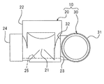
【解決手段】排水ます10は、ます本体20と曲がり管30とを備える。ます本体20は、管路部21と、管路部21から上方に延びる筒部22とを備えている。管路部21の一端には接続口23が形成され、他端には流出口24が形成されている。管路部21は、接続口23側から流出口24側に向かって下り勾配が設けられた管底25を有する。曲がり管30の一端には流入口31が形成され、他端には接続口32が形成されている。曲がり管30の接続口32は、ます本体20の接続口23に回転自在に接続されている。
【選択図】図1
An object of the present invention is to provide a drainage basin for both left and right which is easy to install.
A drainage basin 10 comprises a main body 20 and a bent pipe 30. The main body 20 includes a conduit portion 21 and a cylindrical portion 22 extending upward from the conduit portion 21. A connection port 23 is formed at one end of the conduit portion 21 and an outflow port 24 is formed at the other end. The pipe line part 21 has a pipe bottom 25 provided with a downward gradient from the connection port 23 side toward the outflow port 24 side. An inflow port 31 is formed at one end of the bent pipe 30 and a connection port 32 is formed at the other end. The connection port 32 of the bent pipe 30 is connected to the connection port 23 of the main body 20 so as to be rotatable.
[Selection] Figure 1
Description
本発明は、例えば宅地内の排水管路の曲がり部分等に好適に設置される排水ますに関する。 The present invention relates to a drainage basin that is suitably installed, for example, in a bent portion of a drainage pipe in a residential land.
通常、宅地内の排水管路等には曲がり部分が存在し、このような曲がり部分に排水ますが設けられることがある。曲がり部分に設けられる排水ますは流入口と流出口とを有し、その内部には、流入口から流出口に至る曲がった流路が形成されている。例えば、そのような排水ますの例として、いわゆる90度曲がりの排水ます、すなわち流入口と流出口とが互いに直交する方向に開口した排水ますが知られている。 Usually, there are bent portions in the drainage pipes and the like in residential land, and there are cases where drainage drains are provided at such bent portions. The drainage basin provided in the bent portion has an inflow port and an outflow port, and a curved flow path from the inflow port to the outflow port is formed in the inside. For example, as an example of such a drain, a so-called 90-degree bent drain, that is, a drain with an inlet and an outlet opened in directions orthogonal to each other is known.
ところで、排水管路の管底には、上流側から下流側に向かって下るような勾配が必要である。排水ますの管底にも、流入口側から流出口側に向かって下るような勾配が設けられている。そのため、通常は流入口と流出口とを逆にして用いることはできない。 By the way, the pipe bottom of the drainage pipe line needs to have a gradient that descends from the upstream side toward the downstream side. The bottom of the drainage basin is also provided with a gradient that descends from the inlet side toward the outlet side. For this reason, the inflow port and the outflow port cannot normally be used in reverse.
排水管路の曲がり部分には、進行方向に向かって左側に曲がる左曲がり部分と、進行方向に向かって右側に曲がる右曲がり部分とがある。上述の通り流入口と流出口とを逆にして用いることはできないので、従来、左曲がり部分には左用の排水ますが設置され、右曲がり部分には右用の排水ますが設置されていた。 The bent portion of the drainage pipe has a left bent portion that turns to the left in the traveling direction and a right bent portion that turns to the right in the moving direction. As described above, since the inlet and outlet cannot be used in reverse, conventionally, a drain for left is installed at the left turn, and a drain for right is installed at the right turn.
しかし、施工現場における排水管路の曲がり部分の向きに応じて左用および右用の排水ますを使い分ける場合、予め左用および右用の2種類の排水ますを製造し、在庫として保管しておかなければならない。そのため、製品在庫が増えてしまうという課題がある。 However, if the left and right drainage drains are properly used depending on the direction of the bent part of the drainage pipe at the construction site, two types of drainage drains for the left and right must be manufactured and stored in advance. Don't be. Therefore, there is a problem that product inventory increases.
そこで、管底自体に勾配を設けない排水ますを左右兼用の排水ますとして用いることが提案されている(例えば、特許文献1参照)。この左右兼用の排水ますは、施工現場において、若干傾けて設置される。これにより、結果として、排水ますの管底に勾配が確保される。左右兼用の排水ますを用いることにより、曲がり部分の向きに応じて2種類の排水ますを使い分ける必要がなくなり、製品在庫を減らすことが可能となる。 Therefore, it has been proposed to use a drainage basin having no gradient at the tube bottom itself as a left and right drainage basin (see, for example, Patent Document 1). The left and right drainage basin is installed at a slight angle at the construction site. As a result, a gradient is secured at the bottom of the drainage basin. By using the left and right drainage basins, there is no need to use two types of drainage basins according to the direction of the bent portion, and the product inventory can be reduced.
ところが、上記の左右兼用の排水ますでは、排水ます自体を傾けて設置しなければならないが、適正な勾配を有するように排水ますを設置することは必ずしも容易ではない。 However, with the above-mentioned drainage basin for both left and right, it is necessary to incline the drainage basin itself, but it is not always easy to install the drainage basin so as to have an appropriate gradient.
本発明はかかる点に鑑みてなされたものであり、その目的とするところは、設置が容易な左右兼用の排水ますを提供することにある。 This invention is made | formed in view of this point, The place made into the objective is to provide the drainage basin for both right and left easy to install.
本発明に係る排水ますは、一端に接続口が形成され且つ他端に流出口が形成され、前記接続口側から前記流出口側に向かって下り勾配が設けられた管底を有する管路部と、前記管路部から上方に延びる筒部とを備えたます本体と、一端に流入口が形成され且つ他端に接続口が形成され、当該接続口が前記管路部の接続口に回転自在に接続された曲がり管と、を備えたものである。 The drainage basin according to the present invention has a pipe section having a pipe bottom in which a connection port is formed at one end and an outflow port is formed at the other end, and a downward slope is provided from the connection port side toward the outflow port side. And a main body having a cylindrical portion extending upward from the pipe section, an inflow port is formed at one end, and a connection port is formed at the other end, and the connection port is rotated to the connection port of the pipe section. And a freely connected bent pipe.
上記排水ますによれば、両接続口は回転自在に接続されているので、曲がり管をます本体に対して回転させることができる。上記排水ますは、流入口を正面から見たときに流出口が左側に位置するように曲がり管を回転させることによって、左用の排水ますとして用いることができる。また、流入口を正面から見たときに流出口が右側に位置するように曲がり管を回転させることによって、右用の排水ますとして用いることができる。したがって、排水管路の曲がり部分の向きに応じて曲がり管を適宜回転させることにより、同一の排水ますを左用および右用の排水ますとして使用することができる。よって、2種類の排水ますを使い分ける必要がなくなり、製品在庫を減らすことが可能となる。また、排水ます自体を傾けて設置する必要はないので、設置が容易である。 According to the drainage basin, since both connection ports are rotatably connected, the bent pipe can be further rotated with respect to the main body. The drainage basin can be used as a drainage basin for the left by rotating the bent pipe so that the outlet is located on the left side when the inlet is viewed from the front. Further, when the inflow port is viewed from the front, the bent pipe is rotated so that the outflow port is located on the right side, so that it can be used as a right drain. Therefore, the same drainage can be used as the drainage basin for the left and the right by appropriately rotating the bent pipe according to the direction of the bent portion of the drainage pipe. Therefore, it is not necessary to use two types of drainage basins separately, and the product inventory can be reduced. Moreover, since it is not necessary to incline the drainage tank itself, the installation is easy.
前記曲がり管の流入口の開口方向と接続口の開口方向とのなす角の角度が90度であってもよい。このことにより、進行方向が90度変化する排水管路の曲がり部分に好適に用いられる排水ますを得ることができる。 The angle formed by the opening direction of the inlet of the bent pipe and the opening direction of the connection port may be 90 degrees. This makes it possible to obtain a drainage basin that is suitably used for a bent portion of a drainage pipe whose traveling direction changes by 90 degrees.
前記排水ますは、前記曲がり管の前記ます本体に対する回転に伴って前記曲がり管の接続口から流入口に向かって下り勾配が形成されないように、前記曲がり管の前記ます本体に対する回転範囲を規制するストッパを備えていてもよい。このことにより、排水の円滑な流通が妨げられたり、排水が逆流してしまうことを確実に防止することができる。 The drainage pipe regulates a rotation range of the bent pipe with respect to the main body so that a downward slope is not formed from a connection port of the bent pipe toward the inlet with the rotation of the bent pipe with respect to the main body. A stopper may be provided. As a result, it is possible to reliably prevent the smooth flow of the waste water from being hindered or the drainage from flowing backward.
前記排水ますは、一端に流入口が形成され且つ他端に接続口が形成され、当該接続口が前記曲がり管の流入口に回転自在に接続された他の曲がり管を更に備えていてもよい。 The drainage basin may further include another bent pipe in which an inlet is formed at one end and a connection port is formed at the other end, and the connection port is rotatably connected to the inlet of the bent pipe. .
このことにより、前記曲がり管をます本体に対して回転させると共に、他の曲がり管を前記曲がり管に対して回転させることにより、他の曲がり管の流入口(この流入口は排水ます自体の流入口となる)の位置および向きを比較的自由に変更することができる。したがって、流入口と流入口に接続される配管との位置調整が容易になる。 As a result, the bent pipe is further rotated with respect to the main body, and the other bent pipe is rotated with respect to the bent pipe, so that the inlet of the other bent pipe (this inlet is drained by its own flow). The position and orientation of the entrance can be changed relatively freely. Therefore, the position adjustment between the inlet and the pipe connected to the inlet becomes easy.
前記他の曲がり管の流入口の開口方向と接続口の開口方向とのなす角の角度が90度であってもよい。このことにより、曲がり管の回転方向と他の曲がり管の回転方向とが直交し、排水ますの流出口(すなわち、他の曲がり管の流出口)の位置および向きの調整が容易となる。 The angle formed by the opening direction of the inlet of the other bent pipe and the opening direction of the connection port may be 90 degrees. Accordingly, the rotation direction of the bent pipe and the rotation direction of the other bent pipe are orthogonal to each other, and the position and orientation of the drainage outlet (that is, the outlet of the other bent pipe) can be easily adjusted.
以上のように、本発明によれば、設置が容易な左右兼用の排水ますを提供することができる。 As described above, according to the present invention, it is possible to provide a left and right drainage basin that can be easily installed.
<第1実施形態>
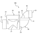
図1に示すように、本実施形態に係る排水ます10は、宅地内の排水管路5の曲がり部分に設置されるものである。排水ます10は、流入管1および流出管2に接続されている。排水は流入管1、排水ます10、流出管2の順に流れる、流入管1、排水ます10、および流出管2は、地中に埋設される排水管路5の一部を構成している。なお、排水の種類は特に限定されず、例えば汚水であってもよく、雨水であってもよい。
<First Embodiment>
As shown in FIG. 1, the
排水ます10は、ます本体20と曲がり管30とを備えている。ます本体20および曲がり管30は樹脂製であり、互いに組み立てられている。
The
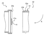
図2に示すように、ます本体20は、水平方向に延びる管路部21と、管路部21から上方に延びる筒部22とから構成されている。管路部21と筒部22とは一体成形されている。ただし、管路部21と筒部22とは別体に形成され、互いに組み立てられていてもよい。管路部21の一端には接続口23が形成され、他端には流出口24が形成されている。管路部21の内部には、接続口23側から流出口24側に向かって下るような勾配を有する管底25が形成されている。図示は省略するが、筒部22には上方から点検筒が嵌め込まれる。この点検筒を通じて、地表から排水ます10の点検が可能となる。流出口24は受口からなり、流出口24には流出管2が嵌め込まれる(図1参照)。ただし、流出口24は受口に限定されず、差口であってもよい。
As shown in FIG. 2, the
図1に示すように、曲がり管30の一端には流入口31が形成され、他端には接続口32が形成されている。曲がり管30は90度湾曲している。符号Rは曲がり管30の湾曲方向を表している。流入口31の開口方向と接続口32の開口方向とのなす角の角度は90度である。ただし、上記角度は必ずしも90度に限られる訳ではない。流入口31は受口からなり、流入口31には流入管1が嵌め込まれる。ただし、流入口31は受口に限定されず、差口であってもよい。曲がり管30の接続口32は、ます本体20の接続口23に回転自在に接続されている。
As shown in FIG. 1, an
次に、接続口23および接続口32の構造を説明する。ただし、互いに回転自在である限り、接続口23および接続口32の構造は以下に説明するような構造に限定されない。
Next, the structure of the
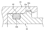
図3は、接続口23および接続口32を鉛直方向に沿って切った場合の縦断面図である。ただし、接続口32については、曲がり管30を上下に立てた状態(言い換えると、流入口31が上方に開口した状態)の縦断面図である。ます本体20の接続口23は受口となっている。接続口23の内周面には、円周状に延びる凹部23aが形成されている。曲がり管30の接続口32は差口となっている。接続口32の外周面には、円周状に延びる凸部32aと、円周状に延びる凹部32bとが形成されている。凹部32bは凸部32aよりも先端側に位置している。
FIG. 3 is a longitudinal sectional view when the
図4は、接続口23と接続口32とが互いに接続された状態の部分断面図である。図4に示すように、接続口32を接続口23に差し込むと、接続口32の凸部32aは接続口23の凹部23aに嵌り込む。凸部32aおよび凹部23aはいずれも円周状に延びているので、凸部32aは軸方向には容易には移動できない一方、周方向には容易に移動可能となる。そのため、接続口32は接続口23に対して回転可能となる。
FIG. 4 is a partial cross-sectional view showing a state in which the
凹部32bの内部には、Oリング等のシール40が嵌め込まれている。このシール40により、接続口23と接続口32との隙間が塞がれている。
A
接続口23に対する接続口32の回転可能な角度範囲は特に限定されないが、本実施形態では180度に設定されている。接続口23を正面から見たときに(言い換えると、接続口23を図3の右方から見たときに)、接続口32は左右に90度ずつ回転可能に構成されている。排水ます10を排水管路5の左曲がり部分に設置する場合には、接続口32は左側に90度回転させればよく、排水ます10を排水管路5の右曲がり部分に設置する場合には、接続口32は右側に90度回転させればよい。本実施形態では、作業者が曲がり管30を左右に回転させた際に接続口32が所定の位置、すなわち左側または右側に90度回転した位置で止まるように、接続口23および接続口32にストッパ41,42が設けられている。
The angle range in which the
ストッパ41,42は、曲がり管30の回転に伴って接続口32から流入口31に向かって下り勾配が形成されないように、曲がり管30の回転範囲を規制する。すなわち、曲がり管30の回転可能な角度範囲が上述の180度の範囲に規制されることによって、曲がり管30の過剰な回転が防止され、曲がり管30は常に適切な姿勢に保たれる。これにより、曲がり管30における排水の円滑な流通が確保され、また、排水の逆流が防止される。
The
ストッパ41は、接続口23の左側および右側にそれぞれ設けられている。ストッパ41の上側は、ストッパ42と当接する当接面41aとなっている。ストッパ42は、接続口32の外周面上に設けられ、半径方向の外側に突出している。ストッパ42は接続口32の上側に設けられている。言い換えると、ストッパ42は、流入口31の開口方向(図3の上方向)に突出している。ストッパ42は接続口32と別体であってもよく、本実施形態のように一体であってもよい。ストッパ42は凸部32aよりも奥側(図3の右側)に配置されている。
The
曲がり管30を左側に回転させると、接続口32のストッパ42が接続口23の左側のストッパ41の当接面41aに当接し、曲がり管30の回転が制限される。これにより、排水ます10は、排水管路5の左曲がり部分に適した左用の排水ますとして利用可能となる(図1参照)。一方、曲がり管30を右側に回転させると、接続口32のストッパ42が接続口23の右側のストッパ41の当接面41aに当接し、曲がり管30の回転が制限される。これにより、排水ます10は、排水管路5の右曲がり部分に適した右用の排水ますとして利用可能となる(図5参照)。ストッパ41,42は、曲がり管30の位置決め手段としても利用される。
When the
以上のように、排水ます10は、曲がり管30をます本体20に対して左右に回転させることによって、左用および右用の排水ますとして利用可能である。よって、2種類の排水ますを使い分ける必要がなくなり、製品在庫を減らすことが可能となる。また、ます本体20の管底25には予め適切な勾配が設けられており、排水ます10自体を傾けて設置する必要はない。したがって、適正な勾配を有するように排水ます10を設置することが容易である。本実施形態によれば、設置が容易な左右兼用の排水ます10を得ることができる。
As described above, the
<第2実施形態>
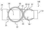
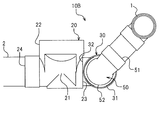
図6〜図8に示すように、第2実施形態に係る排水ます10Bは、第1実施形態に係る排水ます10の曲がり管30に他の曲がり管50を回転自在に接続したものである。第1実施形態と同様の部分には同様の符号を付し、その説明は省略する。
Second Embodiment
As shown in FIGS. 6 to 8, the
図7に示すように、他の曲がり管50の一端には流入口51が形成され、他端には接続口52が形成されている。曲がり管30と同様、曲がり管50は90度湾曲している。流入口51の開口方向と接続口52の開口方向とのなす角の角度は90度である。ただし、上記角度は必ずしも90度に限定される訳ではない。流入口51は受口からなり、流入口51には図示しない流入管が接続される。流入口51の構造は何ら限定されず、例えば、接着されることによって流入管に水密に接続される形式の受口(接着受口)であってもよく、ゴム輪を介して流入管に水密に接続される形式の受口(ゴム輪受口)等であってもよい。また、流入口51は受口に限らず、差口であってもよい。
As shown in FIG. 7, an
本実施形態では、曲がり管30の流入口31は、曲がり管50の接続口52に接続される接続口となっている。接続口52は、曲がり管30の流入口31に対して回転自在に接続されている。互いに回転自在である限り、流入口31および接続口52の構造は何ら限定されない。例えば、第1実施形態の接続口23および接続口32と同様の構造を用いてもよい。
In the present embodiment, the
曲がり管50の材料は何ら限定されず、例えば曲がり管30と同様、樹脂製であってもよい。
The material of the
本実施形態に係る排水ます10Bによれば、曲がり管30をます本体20に対して適宜回転させ、更に曲がり管50を曲がり管30に対して適宜回転させることにより、様々な態様での利用が可能となる。排水ます10Bは、排水管路の様々な曲がり部分に設置することができる。また、曲がり管30および曲がり管50を適宜回転させることにより、流入口51および流出口24の位置関係を適宜に調整することができる。したがって、流入管および流出管との接続に際し、位置の微調整が可能である。
According to the
また、流入口51の高さ位置と流出口24の高さ位置とを異ならせることも可能である(図7参照)。排水ます10Bは、左用または右用の排水ますとしてだけでなく、流入管の高さ位置と流出管の高さ位置とが異なる場所にも利用することができる。
Moreover, it is also possible to make the height position of the
例えば図9および図10に示すように、曲がり管30をます本体20に対して90度回転させ、曲がり管50を曲がり管30に対して所定角度回転させることにより、流入口51の高さ位置を適宜に調整することができる。本実施形態によれば、流入口51と流入管1との位置調整が容易である。なお、図9および図10に示す例では、流入管1は複数の管路部材によって形成されている。
For example, as shown in FIGS. 9 and 10, the
また、例えば図7に示す状態から曲がり管50を左側または右側に45度回転させることとすれば、排水管路において進行方向が45度変化する部分に排水ます10Bを設置することができる。曲がり管50の回転角度は任意に設定することができるので、排水ます10Bは進行方向が45度変化する部分だけでなく、他の部分にも設置することができる。なお、図7に示す状態から曲がり管50を左側に90度回転させると、排水ます10Bは左用の排水ますとして利用可能となる。逆に、図7に示す状態から曲がり管50を右側に90度回転させると、排水ます10Bは右用の排水ますとして利用可能となる。
Further, for example, if the
<他の実施形態>
第2実施形態は、ます本体20と2つの曲がり管30,50とを組み合わせたものであった。しかし、ます本体20と曲がり管30とを一体物とし、または、ます本体20に曲がり管30を回転不能に固定してもよい。この場合、互いに回転不能なます本体20および曲がり管30の全体を、一つのます本体と見なすことができる。この場合であっても、流入口51と流出口24との高さ位置は異なるが、曲がり管50がます本体(すなわち、ます本体20および曲がり管30の組み合わせ)に対して回転可能である限り、左右兼用の排水ますとして利用することができる。
<Other embodiments>
In the second embodiment, the
1 流入口
2 流出口
5 排水管路
10,10B 排水ます
20 ます本体
21 管路部
22 筒部
23 接続口
24 流出口
25 管底
30 曲がり管
31 流入口
32 接続口
50 他の曲がり管
51 流入口
52 接続口
DESCRIPTION OF SYMBOLS 1
Claims (5)
一端に流入口が形成され且つ他端に接続口が形成され、当該接続口が前記管路部の接続口に回転自在に接続された曲がり管と、
を備えた排水ます。 A pipe section having a pipe bottom having a connection port formed at one end and an outlet formed at the other end and provided with a descending slope from the connection port side toward the flow outlet side; and above the pipe section A main body with a cylindrical portion extending to
A bent pipe having an inflow port formed at one end and a connection port formed at the other end, the connection port being rotatably connected to the connection port of the pipe section;
With drainage.
Priority Applications (1)
| Application Number | Priority Date | Filing Date | Title |
|---|---|---|---|
| JP2011069679A JP5780799B2 (en) | 2011-03-28 | 2011-03-28 | Drain |
Applications Claiming Priority (1)
| Application Number | Priority Date | Filing Date | Title |
|---|---|---|---|
| JP2011069679A JP5780799B2 (en) | 2011-03-28 | 2011-03-28 | Drain |
Publications (2)
| Publication Number | Publication Date |
|---|---|
| JP2012202165A true JP2012202165A (en) | 2012-10-22 |
| JP5780799B2 JP5780799B2 (en) | 2015-09-16 |
Family
ID=47183449
Family Applications (1)
| Application Number | Title | Priority Date | Filing Date |
|---|---|---|---|
| JP2011069679A Active JP5780799B2 (en) | 2011-03-28 | 2011-03-28 | Drain |
Country Status (1)
| Country | Link |
|---|---|
| JP (1) | JP5780799B2 (en) |
Citations (4)
| Publication number | Priority date | Publication date | Assignee | Title |
|---|---|---|---|---|
| JPH0312988U (en) * | 1989-06-19 | 1991-02-08 | ||
| JPH0393890U (en) * | 1989-10-31 | 1991-09-25 | ||
| JPH05106266A (en) * | 1991-10-18 | 1993-04-27 | Maezawa Kasei Kogyo Kk | Bent inlet |
| JPH0783377A (en) * | 1993-06-28 | 1995-03-28 | Aron Kasei Co Ltd | PVC small diameter that can be installed in extremely small land |
-
2011
- 2011-03-28 JP JP2011069679A patent/JP5780799B2/en active Active
Patent Citations (4)
| Publication number | Priority date | Publication date | Assignee | Title |
|---|---|---|---|---|
| JPH0312988U (en) * | 1989-06-19 | 1991-02-08 | ||
| JPH0393890U (en) * | 1989-10-31 | 1991-09-25 | ||
| JPH05106266A (en) * | 1991-10-18 | 1993-04-27 | Maezawa Kasei Kogyo Kk | Bent inlet |
| JPH0783377A (en) * | 1993-06-28 | 1995-03-28 | Aron Kasei Co Ltd | PVC small diameter that can be installed in extremely small land |
Also Published As
| Publication number | Publication date |
|---|---|
| JP5780799B2 (en) | 2015-09-16 |
Similar Documents
| Publication | Publication Date | Title |
|---|---|---|
| JP5764405B2 (en) | Joint pipe fitting | |
| JP6693693B2 (en) | Building drainage systems and fittings for drainage systems | |
| JP7412179B2 (en) | Joint pipe, joint pipe with valve | |
| JP5780799B2 (en) | Drain | |
| KR102348570B1 (en) | dual elbow type irrigation gate | |
| JP6019282B2 (en) | Drainage device mounting structure | |
| JP4130902B2 (en) | Universal pipe joint | |
| JP6348033B2 (en) | Drainage mass and drainage system equipped with it | |
| JP4192204B2 (en) | Drainage | |
| JP2023120722A (en) | Backflow prevention joint | |
| TWI376443B (en) | ||
| JP4721267B2 (en) | Merged pipe structure using merged pipe joint | |
| JP2018017322A (en) | Check valve | |
| JP6348031B2 (en) | Drainage mass and drainage system equipped with it | |
| JP2006016780A (en) | Ventilation structure of underfloor piping | |
| JP2005054468A (en) | Drainage header | |
| JP4537965B2 (en) | Multiple inflow drainage | |
| JP2024031186A (en) | Backflow prevention fitting | |
| CN1827930B (en) | Drain tank bucket made of synthetic resin | |
| CN201704749U (en) | Plug for intercepting litters | |
| KR20110033406A (en) | Sewage | |
| JP4471156B2 (en) | Foundation through piping structure and joints for foundation through piping | |
| JP2024099399A (en) | Backflow prevention devices and catch basins equipped with backflow prevention devices | |
| JP6348032B2 (en) | Drainage mass and drainage system equipped with it | |
| JP2026041142A (en) | Elbow, piping system |
Legal Events
| Date | Code | Title | Description |
|---|---|---|---|
| A621 | Written request for application examination |
Free format text: JAPANESE INTERMEDIATE CODE: A621 Effective date: 20140310 |
|
| A977 | Report on retrieval |
Free format text: JAPANESE INTERMEDIATE CODE: A971007 Effective date: 20140917 |
|
| A131 | Notification of reasons for refusal |
Free format text: JAPANESE INTERMEDIATE CODE: A131 Effective date: 20140924 |
|
| A521 | Request for written amendment filed |
Free format text: JAPANESE INTERMEDIATE CODE: A523 Effective date: 20141118 |
|
| A131 | Notification of reasons for refusal |
Free format text: JAPANESE INTERMEDIATE CODE: A131 Effective date: 20150210 |
|
| A521 | Request for written amendment filed |
Free format text: JAPANESE INTERMEDIATE CODE: A523 Effective date: 20150410 |
|
| TRDD | Decision of grant or rejection written | ||
| A01 | Written decision to grant a patent or to grant a registration (utility model) |
Free format text: JAPANESE INTERMEDIATE CODE: A01 Effective date: 20150707 |
|
| A61 | First payment of annual fees (during grant procedure) |
Free format text: JAPANESE INTERMEDIATE CODE: A61 Effective date: 20150714 |
|
| R150 | Certificate of patent or registration of utility model |
Ref document number: 5780799 Country of ref document: JP Free format text: JAPANESE INTERMEDIATE CODE: R150 |
|
| R250 | Receipt of annual fees |
Free format text: JAPANESE INTERMEDIATE CODE: R250 |
|
| R250 | Receipt of annual fees |
Free format text: JAPANESE INTERMEDIATE CODE: R250 |
|
| R250 | Receipt of annual fees |
Free format text: JAPANESE INTERMEDIATE CODE: R250 |
|
| R250 | Receipt of annual fees |
Free format text: JAPANESE INTERMEDIATE CODE: R250 |
|
| R250 | Receipt of annual fees |
Free format text: JAPANESE INTERMEDIATE CODE: R250 |
|
| R250 | Receipt of annual fees |
Free format text: JAPANESE INTERMEDIATE CODE: R250 |
|
| R250 | Receipt of annual fees |
Free format text: JAPANESE INTERMEDIATE CODE: R250 |
|
| R250 | Receipt of annual fees |
Free format text: JAPANESE INTERMEDIATE CODE: R250 |
|
| R250 | Receipt of annual fees |
Free format text: JAPANESE INTERMEDIATE CODE: R250 |