JP2012199099A - Illumination control system - Google Patents

Illumination control system Download PDF

Info

Publication number
JP2012199099A
JP2012199099A JP2011062989A JP2011062989A JP2012199099A JP 2012199099 A JP2012199099 A JP 2012199099A JP 2011062989 A JP2011062989 A JP 2011062989A JP 2011062989 A JP2011062989 A JP 2011062989A JP 2012199099 A JP2012199099 A JP 2012199099A
Authority
JP
Japan
Prior art keywords
lighting
load
control
address
switch
Prior art date
Legal status (The legal status is an assumption and is not a legal conclusion. Google has not performed a legal analysis and makes no representation as to the accuracy of the status listed.)
Withdrawn
Application number
JP2011062989A
Other languages
Japanese (ja)
Inventor
Hiroshi Miura
啓 三浦
Koichiro Hashimoto
幸一郎 橋本
Current Assignee (The listed assignees may be inaccurate. Google has not performed a legal analysis and makes no representation or warranty as to the accuracy of the list.)
Panasonic Corp
Original Assignee
Panasonic Corp
Priority date (The priority date is an assumption and is not a legal conclusion. Google has not performed a legal analysis and makes no representation as to the accuracy of the date listed.)
Filing date
Publication date
Application filed by Panasonic Corp filed Critical Panasonic Corp
Priority to JP2011062989A priority Critical patent/JP2012199099A/en
Publication of JP2012199099A publication Critical patent/JP2012199099A/en
Withdrawn legal-status Critical Current

Links

Images

Abstract

PROBLEM TO BE SOLVED: To prevent the number of times of flashing illumination loads from deviating when thinning control of the illumination loads is performed in an illumination control system.SOLUTION: In an illumination control system 1, each switch actuator 6, 7 includes a switch SW which is addressed to exchange illumination loads 9 to be lighted every time when thinning control is performed to omit lighting of some illumination loads 9 out of a plurality of illumination loads 9, and transmits a control signal including the address to a transmission unit 2 when the switch SW is depressed. The transmission unit 2 transmits a control signal for performing the thinning control of the illumination loads 9 corresponding to the address included in the control signal to a relay control terminal 3. With such a configuration, the number of times of flashing the illumination loads can be prevented from deviating when thinning control of the illumination loads 9 is performed.

Description

本発明は、所定の制御信号に基づいて照明負荷を制御する照明制御システムに関する。   The present invention relates to a lighting control system that controls a lighting load based on a predetermined control signal.

従来より、制御対象となる照明負荷などの負荷の状態を変化させるための入力端末器と、照明負荷が接続された負荷制御端末器とが信号線を介して伝送ユニットにそれぞれ接続された照明制御システムが知られている。この照明制御システムでは、入力端末器から送信される伝送信号に基づいて、伝送ユニットが、入力端末器に関連付けられたアドレス情報と対応する負荷制御端末器を介して、この負荷制御端末器に接続する照明負荷を制御する。   Conventionally, an illumination control in which an input terminal for changing a load state such as an illumination load to be controlled and a load control terminal to which the illumination load is connected are connected to the transmission unit via a signal line, respectively. The system is known. In this lighting control system, based on the transmission signal transmitted from the input terminal, the transmission unit is connected to the load control terminal via the load control terminal corresponding to the address information associated with the input terminal. Control the lighting load.

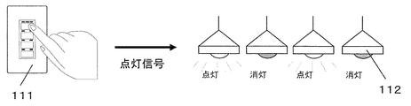
この種の照明制御システムでは、図11に示すように、壁面に設けられた負荷操作器111を介して、複数の照明負荷112から一部の照明負荷112の点灯を省く間引き点灯の制御ができる。この場合、負荷操作器111の1つのスイッチに、同一のグループの複数の照明負荷を同一の制御状態へと一括的に制御するための1つのグループアドレスを設定する。または、負荷操作器111の1つのスイッチに、各照明負荷112を予め定めた所定の制御状態へ一括的に制御するための1つのパターンアドレスを設定する。ユーザは、上記アドレス設定がなされた負荷操作器111のスイッチを押下し、複数の照明負荷をパターン制御やグループ制御して間引き制御を実現する。   In this type of lighting control system, as shown in FIG. 11, it is possible to control thinning lighting by omitting lighting of some lighting loads 112 from a plurality of lighting loads 112 via a load operation device 111 provided on a wall surface. . In this case, one group address for collectively controlling a plurality of lighting loads in the same group to the same control state is set in one switch of the load operation device 111. Alternatively, one pattern address for collectively controlling each lighting load 112 to a predetermined control state is set in one switch of the load operation device 111. The user presses down the switch of the load operating device 111 for which the address setting is made, and implements thinning control by pattern control or group control of a plurality of lighting loads.

そして、近年、照明制御システムでは、周囲の照度を検知する照度センサにより検出される周囲環境の照度に合わせて、自動的に、明るい昼間や昼休みなど、照明負荷の間引き制御を行うことで省エネルギーを図る制御が行われている。また、LEDの累積点灯時間が均一になるようにLEDを間引き点灯させるトンネル照明負荷が知れられている(例えば、特許文献1参照)。   In recent years, the lighting control system automatically saves energy by performing thinning control of the lighting load such as bright daytime or lunch break automatically according to the illuminance of the surrounding environment detected by the illuminance sensor that detects the illuminance of the surroundings. Control is performed. In addition, a tunnel illumination load is known in which LEDs are thinned and lit so that the cumulative lighting time of the LEDs becomes uniform (see, for example, Patent Document 1).

特開2005−142116号公報JP 2005-142116 A

しかしながら、上記従来の照明制御システムにおいて間引き制御を行う際、図11に示すように、間引きして点滅させる照明負荷112が固定されている。このため、照明負荷の点滅回数に偏りが生じ、点滅回数の多い照明負荷やリレーの寿命が早くなり、照明負荷の明るさにバラツキが生じ、その結果、ユーザに違和感を与えてしまうという問題がある。   However, when the thinning control is performed in the conventional lighting control system, as shown in FIG. 11, the lighting load 112 for thinning and blinking is fixed. For this reason, there is a problem in that the number of times the lighting load blinks is biased, the life of lighting loads and relays with many blinking times is shortened, and the brightness of the lighting load varies, resulting in a sense of discomfort to the user. is there.

また、従来の照明制御システムでは、上記のように間引き制御に用いられるパターンアドレスやグループアドレスが負荷操作器に一度設定されると、間引き制御を行う照明負荷を変更するにはアドレス設定器を用いて再度アドレス設定からやり直す必要がある。この結果、ユーザの手間を要するという問題もある。   Also, in the conventional lighting control system, once the pattern address and group address used for thinning control are set in the load operation unit as described above, the address setting unit is used to change the lighting load for performing thinning control. It is necessary to start again from address setting. As a result, there is a problem that it takes time and effort of the user.

さらに、図12(a)に示すように、従来の液晶付き負荷操作器121の液晶表示部122においては、OFF時に操作ボタン123の左側に緑表示124、ON時に操作ボタン123の右側に赤表示125がなされる。図12(b)に示すスイッチ式の負荷操作器126では、操作ボタンの左上、右上に設けられたLED127,128をそれぞれOFF時には緑点灯(127)、ON時には赤点灯(128)する。このため、従来の負荷操作器121,126では、照明負荷のON状態又はOFF状態を操作面において確認することはできるが、消灯している照明負荷があった場合、間引き制御のために消灯しているのか、寿命により消灯しているのか分からない。すなわち、ユーザやメンテナンス業者は、負荷操作器121,126の操作面から視覚的に間引き点灯状態を確認することができないという問題がある。   Further, as shown in FIG. 12A, in the liquid crystal display unit 122 of the conventional load operation device with liquid crystal 121, green is displayed on the left side of the operation button 123 when OFF, and red is displayed on the right side of the operation button 123 when ON. 125 is made. In the switch type load manipulator 126 shown in FIG. 12B, the LEDs 127 and 128 provided on the upper left and upper right of the operation button are lit green (127) when turned off and red (128) when turned on. For this reason, in the conventional load operating devices 121 and 126, it is possible to check the ON or OFF state of the lighting load on the operation surface. However, when there is a lighting load that is turned off, the lighting load is turned off for thinning control. I do n’t know if it ’s off or it ’s turned off because of its life. That is, there is a problem that the user or the maintenance contractor cannot visually confirm the thinning-out lighting state from the operation surface of the load operation device 121 or 126.

本発明は、上記課題に鑑みてなされたものであり、照明負荷の間引き制御において、照明負荷の点滅回数に偏りが生じることを防止した照明制御システムを提供することを目的とする。また、照明負荷の間引き制御状態を視覚的に認識できる負荷操作器を備える照明制御システムを提供することをも目的とする。   The present invention has been made in view of the above problems, and an object of the present invention is to provide a lighting control system that prevents the lighting load from blinking in the thinning-out control of the lighting load. It is another object of the present invention to provide an illumination control system including a load operation device that can visually recognize a thinning-out control state of an illumination load.

上記目的を達成するために本発明は、制御対象となる照明負荷の状態を変化させるために操作され、該操作に応じて信号を出力する負荷操作器と、前記負荷操作器の制御対象となる照明負荷を制御する制御端末器と、信号線を介して前記制御端末器及び前記負荷操作器と接続され伝送信号を送受信する伝送ユニットと、を備える照明制御システムにおいて、前記負荷操作器は、複数の照明負荷から一部の照明負荷の点灯を省く間引き制御する際、点灯させるごとに点灯する照明負荷が入れ替わるようにアドレス設定されたスイッチ手段と、前記スイッチ手段が押下された場合、前記アドレスを含む制御信号を前記伝送ユニットに送信する送受信手段と、を備え、前記伝送ユニットは、前記制御信号に含まれるアドレスに対応する照明負荷を間引き制御するための制御信号を前記制御端末器に送信する制御手段を備えた、ことを特徴とする。   In order to achieve the above object, the present invention is operated to change the state of a lighting load to be controlled, and outputs a signal in response to the operation, and is a control target of the load operating device. In a lighting control system comprising: a control terminal that controls a lighting load; and a transmission unit that is connected to the control terminal and the load operation unit via a signal line and transmits and receives a transmission signal, the load operation unit includes a plurality of load operation units. When the thinning control is performed by omitting lighting of some lighting loads from the lighting load, switch means set to an address so that the lighting load to be turned on every time it is turned on, and when the switch means is pressed, the address is set. Transmitting / receiving means for transmitting a control signal including the transmission signal to the transmission unit, the transmission unit interposing a lighting load corresponding to an address included in the control signal. A control signal for air control comprising a control means for transmitting to said control terminal, and wherein the.

この照明制御システムにおいて、前記アドレスには、間引き制御において一部の照明負荷を点灯させるパターンアドレス、間引き制御において前記一部の照明負荷以外の照明負荷を点灯させるパターンアドレス、全ての照明負荷を点灯させるパターンアドレス、及び全ての照明負荷を消灯させるパターンアドレスが含まれることが好ましい。   In this lighting control system, the address includes a pattern address for lighting a part of the lighting load in the thinning-out control, a pattern address for lighting a lighting load other than the part of the lighting load in the thinning-out control, and all the lighting loads. It is preferable that a pattern address to be turned off and a pattern address to turn off all the lighting loads are included.

この照明制御システムにおいて、前記負荷操作器は、照明負荷の点灯状態を表示する表示部を有し、前記表示部は、間引き点灯状態と、そうでない状態とで表示色又は表示領域を異ならせたことが好ましい。   In this lighting control system, the load operating device has a display unit that displays a lighting state of a lighting load, and the display unit has a display color or a display area that is different between a thinned-out lighting state and a state that is not. It is preferable.

この照明制御システムにおいて、前記表示部は、液晶表示部であり、前記間引き点灯状態においては、照明負荷の全点灯時において所定色で表示される前記液晶表示部の領域の半分の領域を前記所定色で表示することが好ましい。   In this illumination control system, the display unit is a liquid crystal display unit, and in the thinned lighting state, half of the region of the liquid crystal display unit displayed in a predetermined color when the lighting load is fully lit is the predetermined unit. It is preferable to display in color.

この照明制御システムにおいて、前記表示部は、LED表示部であり、前記間引き点灯状態においては、照明負荷の全点灯時において所定色で表示される前記LED表示部を他の色で表示することが好ましい。   In this illumination control system, the display unit is an LED display unit, and in the thinned lighting state, the LED display unit displayed in a predetermined color when the lighting load is fully lit can be displayed in another color. preferable.

本発明によれば、照明制御システムにおいて、負荷操作器は、間引き点灯させるごとに点灯する照明負荷が入れ替わるようにアドレス設定されたスイッチを有する。このため、間引き制御において、照明負荷の点滅回数に偏りが生じることを防止できる。   According to the present invention, in the lighting control system, the load operating device has a switch whose address is set so that the lighting load to be turned on is switched every time thinning-out is performed. For this reason, it is possible to prevent the lighting load from blinking in the thinning-out control.

また、照明制御システムの負荷操作器は、間引き点灯状態と、そうでない状態とで表示色又は表示領域を異ならせて照明負荷の点灯状態を表示する表示部を有するため、照明負荷の間引き制御の状態を視覚的に認識できる。   In addition, the load controller of the lighting control system has a display unit that displays the lighting state of the lighting load by changing the display color or the display area between the thinned lighting state and the non-thinning lighting state. The state can be recognized visually.

本発明の実施の形態1に係る照明制御システムの構成図である。It is a block diagram of the illumination control system which concerns on Embodiment 1 of this invention. 同上照明制御システムにおける間引き制御の説明図である。It is explanatory drawing of the thinning-out control in an illumination control system same as the above. 同上照明制御システムの伝送ユニットが保持する情報テーブルの一例を示す図である。It is a figure which shows an example of the information table which the transmission unit of a lighting control system same as the above hold | maintains. 本発明の実施の形態2に係る照明制御システムにおける間引き制御の説明図である。It is explanatory drawing of the thinning-out control in the illumination control system which concerns on Embodiment 2 of this invention. 同上実施の形態2の第1の変形例に係る照明制御システムの負荷操作器の前面図である。It is a front view of the load operating device of the illumination control system which concerns on the 1st modification of Embodiment 2 same as the above. (a)本発明の実施の形態3に係る照明制御システムの説明図、(b)同上照明制御システムの負荷操作器に設定されるパターンアドレスの一例を示す図である。(A) It is explanatory drawing of the illumination control system which concerns on Embodiment 3 of this invention, (b) It is a figure which shows an example of the pattern address set to the load operation device of the illumination control system same as the above. (a)同上実施の形態3の第1の変形例に係る照明制御システムの間引き制御の説明図、(b)同上照明制御システムの負荷操作器に設定されるグループアドレスの一例を示す図である。(A) Explanatory drawing of thinning-out control of the illumination control system which concerns on the 1st modification of Embodiment 3 same as the above, (b) It is a figure which shows an example of the group address set to the load operation device of the illumination control system same as the above. . (a)本発明の実施の形態4に係る照明制御システムの液晶付負荷操作器の表示画面の一例を示す図、(b)同上照明制御システムに係る負荷操作器のLED表示部の前面図、(c)同上LED表示部の前面図である。(A) The figure which shows an example of the display screen of the load operating device with a liquid crystal of the illumination control system which concerns on Embodiment 4 of this invention, (b) The front view of the LED display part of the load operating device which concerns on an illumination control system same as the above, (C) It is a front view of an LED display part same as the above. (a)及び(b)はそれぞれ同上実施の形態4の第1の変形例に係る照明制御システムの負荷操作器の前面図である。(A) And (b) is a front view of the load operation device of the illumination control system which concerns on the 1st modification of Embodiment 4 same as the above, respectively. (a)及び(b)はそれぞれ同上実施の形態4の第2の変形例に係る照明制御システムの負荷操作器の前面図である。(A) And (b) is a front view of the load operation device of the illumination control system which concerns on the 2nd modification of Embodiment 4 same as the above, respectively. 従来の照明制御システムにおける間引き制御の説明図である。It is explanatory drawing of the thinning-out control in the conventional illumination control system. (a)従来の照明制御システムに用いる液晶付き負荷操作器の前面図、(b)同上照明制御システムに用いる負荷操作器の前面図である。(A) It is a front view of the load operating device with a liquid crystal used for the conventional lighting control system, (b) It is a front view of the load operating device used for a lighting control system same as the above.

本発明の実施の形態に係る照明制御システムに関して図面を参照して説明する。   A lighting control system according to an embodiment of the present invention will be described with reference to the drawings.

(実施の形態1)
図1は、本実施の形態1に係る照明制御システム1の構成を示す。この照明制御システム1は、伝送ユニット2と、リレー制御端末器(制御端末器)3と、リモコンリレー4と、リモコントランス5と、スイッチ操作器(負荷操作器)6と、液晶付スイッチ操作器(負荷操作器)7と、照度センサ8と、照明負荷9とを備えている。リレー制御端末器3、スイッチ操作器6、液晶付スイッチ操作器7、及び照度センサ8は、2線式の信号線を介して伝送ユニット2と相互に接続されている。伝送ユニット2との情報のやり取りは、信号線に割り込み式時分割多重伝送方式で伝送される伝送信号を通して行われる。
(Embodiment 1)
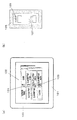
FIG. 1 shows a configuration of a lighting control system 1 according to the first embodiment. The lighting control system 1 includes a transmission unit 2, a relay control terminal (control terminal) 3, a remote control relay 4, a remote control transformer 5, a switch operation unit (load operation unit) 6, and a switch operation unit with liquid crystal. (Load operation device) 7, an illuminance sensor 8, and an illumination load 9 are provided. The relay control terminal 3, the switch operator 6, the switch operator with liquid crystal 7, and the illuminance sensor 8 are mutually connected to the transmission unit 2 via a two-wire signal line. Information exchange with the transmission unit 2 is performed through a transmission signal transmitted to the signal line by the interrupt time division multiplex transmission method.

この照明制御システム1では、室内の壁面などに埋め込まれたスイッチ操作器6や液晶付スイッチ操作器7、照度センサ8を用いて、複数の照明負荷9から一部の照明負荷9の点灯を省く間引き制御や照明負荷9のオン/オフ状態の操作を行うことができる。   In this illumination control system 1, lighting of some illumination loads 9 is omitted from a plurality of illumination loads 9 using a switch operator 6, a switch operator 7 with liquid crystal, and an illuminance sensor 8 embedded in an indoor wall surface. It is possible to perform the thinning control and the on / off operation of the illumination load 9.

伝送ユニット2は、スイッチ操作器6、液晶付スイッチ操作器7、及び照度センサ8からの伝送信号に基づいて、伝送信号に含まれるアドレス情報から制御対象となる照明負荷9を特定すると共に、照明負荷9に対する制御状態(オン、オフや調光状態)を特定する。そして、伝送ユニット2は、制御対象となる照明負荷9と対応するリレー制御端末器3に対して、照明負荷9のアドレス情報と、その制御状態とを制御指令信号として送信する制御部を有している。   The transmission unit 2 specifies the illumination load 9 to be controlled from the address information included in the transmission signal based on the transmission signals from the switch operator 6, the switch operator with liquid crystal 7, and the illuminance sensor 8, and the illumination unit 9 The control state (ON, OFF, dimming state) for the load 9 is specified. And the transmission unit 2 has a control part which transmits the address information of the lighting load 9 and its control state as a control command signal to the relay control terminal 3 corresponding to the lighting load 9 to be controlled. ing.

リレー制御端末器3は、リレーの制御状態に応じて照明負荷9の状態を制御する負荷制御端末器としての機能を担っている。リレー制御端末器3は、伝送ユニット2からの伝送信号に基づいて、自己に接続するリモコンリレー4のうち、制御対象となる照明負荷9に対応するリモコンリレー4に対して制御信号を送ることにより、リモコンリレー4の状態を制御する。リモコンリレー4の個々のリレーは、リレー制御端末器3に制御されて、ブレーカ電源(AC100又は200V)10などからの商用交流をオン/オフすることで、照明負荷9をオン状態やオフ状態にする。   The relay control terminal 3 has a function as a load control terminal that controls the state of the lighting load 9 according to the control state of the relay. Based on the transmission signal from the transmission unit 2, the relay control terminal 3 sends a control signal to the remote control relay 4 corresponding to the lighting load 9 to be controlled among the remote control relays 4 connected to itself. The state of the remote control relay 4 is controlled. Each relay of the remote control relay 4 is controlled by the relay control terminal 3 to turn on / off the commercial alternating current from the breaker power source (AC 100 or 200 V) 10 or the like, so that the lighting load 9 is turned on or off. To do.

リモコントランス5は、リレー制御端末器3、及びリモコンリレー4に駆動用の電力を供給する。   The remote control transformer 5 supplies driving power to the relay control terminal 3 and the remote control relay 4.

スイッチ操作器6及び液晶付スイッチ操作器7は、照明負荷9を制御するための制御指令を出力するための入力端末器としての機能を担っている。具体的には、スイッチ操作器6,7は、例えば室内などの任意の壁面に設置されており、照明負荷9を利用するユーザによってプッシュ操作が可能な端末器である。スイッチ操作器6は、スイッチSW(スイッチ手段)のいずれかが操作されるのに応じて、そのスイッチSWに関連付けられているアドレス情報と、スイッチSWの操作状態とを制御信号として伝送ユニット2に送信する送受信手段を備えている。液晶付スイッチ操作器7は、液晶タッチパネルを有し、ユーザが画面表示されるスイッチSW(スイッチ手段)に触れることで、操作状態を制御信号として伝送ユニット2に送信する送受信手段を備えている。   The switch operator 6 and the switch operator with liquid crystal 7 have a function as an input terminal for outputting a control command for controlling the illumination load 9. Specifically, the switch operating devices 6 and 7 are terminals that are installed on an arbitrary wall surface such as a room and can be pushed by a user using the lighting load 9. The switch operating device 6 sends the address information associated with the switch SW and the operation state of the switch SW to the transmission unit 2 as control signals in response to any one of the switches SW (switch means) being operated. Transmitting and receiving means is provided. The switch operator with liquid crystal 7 has a liquid crystal touch panel, and includes transmission / reception means for transmitting an operation state to the transmission unit 2 as a control signal when the user touches a switch SW (switch means) displayed on the screen.

スイッチ操作器6,7の各スイッチSWには、照明負荷9の間引き点灯制御を行うため、アドレス情報としてグループアドレスやパターンアドレスが設定されている。このスイッチSWのプッシュ操作に応じて、アドレスに対応する照明負荷9は、間引き点灯状態へと移行する。   A group address and a pattern address are set as address information in each switch SW of the switch operating units 6 and 7 in order to perform thinning lighting control of the lighting load 9. In response to the push operation of the switch SW, the illumination load 9 corresponding to the address shifts to the thinned-out lighting state.

照度センサ8は、天井面などに設置され、検知領域周辺の明るさを検知(検知照度100〜2000ルクス等)する。そして、照度センサ8は、検知された照度に基づいて照明負荷9を制御するためアドレス情報や制御情報を含む制御信号を、伝送信号線を介して伝送ユニット2に対して送信する。照度センサ8には、照度検出のON/OFF設定、照度値を設定する照度設定用スイッチなどが備わっている。なお、照明制御システム1が備えるセンサ機能は照度センサ8に限定されるものではなく、例えば人の動きの温度変化を検知して照明を制御する熱線センサなどを用いることもできる。   The illuminance sensor 8 is installed on a ceiling surface or the like, and detects the brightness around the detection area (detected illuminance 100 to 2000 lux or the like). The illuminance sensor 8 transmits a control signal including address information and control information to the transmission unit 2 via the transmission signal line in order to control the illumination load 9 based on the detected illuminance. The illuminance sensor 8 includes illuminance detection ON / OFF setting, an illuminance setting switch for setting an illuminance value, and the like. In addition, the sensor function with which the illumination control system 1 is provided is not limited to the illuminance sensor 8, and for example, a heat ray sensor that controls illumination by detecting a temperature change of a person's movement can be used.

これらのスイッチ操作器6、液晶付スイッチ操作器7、及び照度センサ8は、照明負荷9を制御するための負荷操作器であるが、負荷操作器はこれらに限定されるものではない。すなわち、その他の負荷操作器として、人体の熱を検出する熱線センサ、年間プログラムや時間帯プログラムに基づいて照明負荷9の点灯状態(オン状態、オフ状態や調光状態)を制御するタイマユニットや、接点入力端末器を用いることもできる。この接点入力端末器は、他システムからの信号を接続することで他システムからの制御信号に基づいて照明負荷9の間引き制御におけるグループ制御やパターン制御を可能とする。   The switch operating unit 6, the switch operating unit with liquid crystal 7, and the illuminance sensor 8 are load operating units for controlling the lighting load 9, but the load operating unit is not limited to these. That is, as other load operating devices, a heat ray sensor that detects the heat of the human body, a timer unit that controls the lighting state (on state, off state, dimming state) of the lighting load 9 based on an annual program or a time zone program, A contact input terminal can also be used. This contact input terminal enables group control and pattern control in thinning-out control of the lighting load 9 based on a control signal from another system by connecting a signal from another system.

照明負荷9は、負荷アドレスによって一意に特定することができる。具体的には、リレー制御端末器3には、負荷チャネル(Ch)と呼ばれる固有の識別子が割り当てられており、リレー制御端末器3に接続するリモコンリレー4には、負荷ナンバー(Nm)を呼ばれる固有の識別子が割り当てられている。負荷チャネル(Ch)と、負荷ナンバー(Nm)とを組み合わせることにより、負荷アドレス(Ch−Nm)が構成される。   The lighting load 9 can be uniquely specified by the load address. Specifically, a unique identifier called a load channel (Ch) is assigned to the relay control terminal 3, and a load number (Nm) is called to the remote control relay 4 connected to the relay control terminal 3. A unique identifier is assigned. The load address (Ch-Nm) is configured by combining the load channel (Ch) and the load number (Nm).

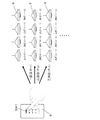
次に、本実施の形態1における照明制御システム1の間引き制御に関して説明する。図2に示すように、スイッチ操作器6を用いて照明負荷9の間引き制御を行う際、一部の照明負荷9を点灯させ、残りの照明負荷9を点灯させないこととし、且つ点灯させる毎に点灯する照明が入れ替わるようになる。すなわち、一回目は奇数番目の照明負荷9を点灯させ偶数番目の照明負荷9を消灯させ、二回目には、偶数番目の照明負荷9を点灯させ奇数番目の照明負荷9を消灯させ、三回目以降はこの制御を繰り返す。なお、図2の4つの照明負荷9の負荷アドレスは、左側から「0−1」、「0−2」、「1−1」、「1−2」とする。   Next, the thinning control of the illumination control system 1 according to the first embodiment will be described. As shown in FIG. 2, when performing the thinning-out control of the lighting load 9 using the switch operating device 6, it is assumed that a part of the lighting load 9 is turned on and the remaining lighting load 9 is not turned on and every time the lighting load 9 is turned on. The lighting that comes on will be switched. That is, the odd-numbered illumination load 9 is turned on and the even-numbered illumination load 9 is turned off for the first time, and the even-numbered illumination load 9 is turned on and the odd-numbered illumination load 9 is turned off the second time. Thereafter, this control is repeated. The load addresses of the four lighting loads 9 in FIG. 2 are “0-1”, “0-2”, “1-1”, and “1-2” from the left side.

次に、照明負荷9の間引き制御を行うための制御処理に関して説明する。スイッチ操作器6には、図2に示すように、複数のスイッチの1つに間引き制御用のスイッチSW1が設けられる。このスイッチSW1には、アドレス設定器においてパターンアドレス「P−1」及び「P−2」が交互に設定される。   Next, control processing for performing the thinning-out control of the illumination load 9 will be described. As shown in FIG. 2, the switch operating unit 6 is provided with a switch SW1 for thinning control in one of the plurality of switches. In the switch SW1, pattern addresses “P-1” and “P-2” are alternately set by the address setter.

なお、スイッチ操作器6,7に設定されるアドレスには、個別アドレス、グループアドレス、又はパターンアドレスを含む。個別アドレスは、個別制御の対象となる照明負荷9を特定するための情報であり、負荷アドレス(個別「0−1」など)に該当する。グループアドレスは、複数の照明負荷9を同一の制御状態へと一括的に制御するためグループ制御の対象となるグループを特定するための情報であり、予め設定された個々のグループに付与された番号(「G−1」など)がこれに該当する。パターンアドレスは、複数の照明負荷9を、それぞれの照明負荷9に予め定められた所定の制御状態へと一括的に制御するパターンを特定するための情報であり、予め設定された個々のパターンに付与された番号(「P−1」など)である。   The addresses set in the switch operating devices 6 and 7 include individual addresses, group addresses, or pattern addresses. The individual address is information for specifying the lighting load 9 to be individually controlled, and corresponds to a load address (individual “0-1” or the like). The group address is information for specifying a group to be subjected to group control in order to collectively control the plurality of lighting loads 9 to the same control state, and is a number assigned to each preset group. ("G-1" etc.) corresponds to this. The pattern address is information for specifying a pattern for collectively controlling a plurality of lighting loads 9 to a predetermined control state predetermined for each lighting load 9, and is assigned to each preset pattern. It is a number assigned (such as “P-1”).

ユーザが、照明負荷9の間引き制御を行うため、スイッチSW1を押下すると、パターンアドレスP−1及びP−2が交互に制御信号に付加されて伝送ユニット2に送信される。伝送ユニット2は、内部のプロセッサの制御のもと、スイッチ操作器6からの伝送信号に基づいて、スイッチ操作器6の各スイッチに関連付けられたアドレス情報から制御対象となる照明負荷9を特定すると共に、照明負荷9に対する制御状態を特定する。そして、伝送ユニット2が備える制御部は、制御対象となる照明負荷9と対応するリレー制御端末器3に対して、照明負荷9のアドレス情報と、その制御状態とを制御指令として送信することで、リモコンリレー4がリレーを動作させて照明負荷9を間引き制御する。   When the user depresses the switch SW1 to perform the thinning control of the lighting load 9, the pattern addresses P-1 and P-2 are alternately added to the control signal and transmitted to the transmission unit 2. The transmission unit 2 specifies the lighting load 9 to be controlled from the address information associated with each switch of the switch operator 6 based on the transmission signal from the switch operator 6 under the control of the internal processor. At the same time, the control state for the lighting load 9 is specified. And the control part with which the transmission unit 2 is provided transmits the address information of the lighting load 9, and its control state as a control command with respect to the relay control terminal 3 corresponding to the lighting load 9 used as a control object. The remote control relay 4 operates the relay to control the lighting load 9 to be thinned out.

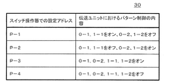
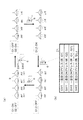
次に、伝送ユニット2におけるアドレス設定に関して説明する。図3に示すように、伝送ユニット2は、例えば、個々のパターンアドレス毎に、そのパターンに割り当てられる照明負荷9の負荷アドレスと、その照明負荷9のパターン状態(オン状態、オフ状態)との対応関係を示した情報テーブル30を保持する。この情報テーブル30は、フル2線式信号線に接続されるアドレス設定器を用いて設定され、「P−2」の制御内容を「負荷アドレス0−1,1−1をオフ、0−2,1−2をオン」などと設定する。伝送ユニット2は、例えばスイッチ操作器6から「P−2」を含む伝送信号を受信した場合、情報テーブル30を検索し、この「P−2」に該当する複数の照明負荷9の制御状態(「負荷アドレス0−1,1−1をオフ、0−2,1−2をオン」)を特定する。   Next, address setting in the transmission unit 2 will be described. As shown in FIG. 3, for example, the transmission unit 2 includes, for each pattern address, the load address of the lighting load 9 assigned to the pattern and the pattern state (on state, off state) of the lighting load 9. An information table 30 indicating the correspondence relationship is held. This information table 30 is set by using an address setter connected to a full 2-wire signal line, and the control content of “P-2” is set to “load addresses 0-1 and 1-1 turned off, 0-2. , 1-2 is turned on. " For example, when the transmission unit 2 receives a transmission signal including “P-2” from the switch operating device 6, the transmission unit 2 searches the information table 30 and controls the control states of the plurality of lighting loads 9 corresponding to this “P-2” ( “Load addresses 0-1 and 1-1 are off and 0-2 and 1-2 are on”).

なお、グループアドレスの場合も同様であり、伝送ユニット2は、個々のグループアドレス毎に、そのグループに割り当てられる照明負荷9の負荷アドレスを示した情報テーブルを保持する。情報テーブルは、アドレス設定器を用いて設定され、例えば「G−1」の制御範囲を「負荷アドレス0−1,0−2,1−1,1−2」と記憶する。伝送ユニット2は、スイッチ操作器6,7などからグループアドレス(「G−1」)を取得した場合には、情報テーブルを検索することで、このグループアドレスに該当する複数の照明負荷9の制御状態(「0−1,0−2,1−1,1−2」)を特定する。   The same applies to the group address, and the transmission unit 2 holds an information table indicating the load address of the lighting load 9 assigned to the group for each group address. The information table is set using an address setter, and for example, the control range of “G-1” is stored as “load addresses 0-1, 0-2, 1-1, 1-2”. When the transmission unit 2 acquires a group address (“G-1”) from the switch operating devices 6 and 7, the transmission unit 2 searches the information table to control the plurality of lighting loads 9 corresponding to the group address. The state ("0-1, 0-2, 1-1, 1-2") is specified.

以上の説明のように、本実施の形態1では、ユーザが照明負荷9の間引き制御を行う場合、スイッチ操作器6のスイッチSW1を押下するごとに点灯する照明負荷9が入れ替わる。従って、間引き制御において、照明負荷9の点灯を交互に行い、照明負荷9やリモコンリレー4の動作回数が平均化され、照明負荷9やリモコンリレー4の寿命にばらつきがなくなり、照明負荷9の明るさに差が生じにくい。   As described above, in the first embodiment, when the user performs the thinning control of the lighting load 9, the lighting load 9 that is turned on is switched every time the switch SW1 of the switch operating device 6 is pressed. Therefore, in the thinning-out control, the lighting load 9 is alternately turned on, the number of operations of the lighting load 9 and the remote control relay 4 is averaged, and the life of the lighting load 9 and the remote control relay 4 is not varied. Differences are unlikely to occur.

また、間引き制御する照明負荷9の範囲を切り替えて制御したい場合などにおいて、スイッチ操作器6,7のアドレス設定を変更する手間が省け、簡単に間引き制御できる。従って、照明制御システム1を従来の照明制御システムに適用でき、照明負荷9の延命を図ることができる。   Further, when it is desired to switch and control the range of the lighting load 9 to be thinned out, it is possible to easily perform the thinning out by eliminating the trouble of changing the address setting of the switch operating devices 6 and 7. Therefore, the illumination control system 1 can be applied to a conventional illumination control system, and the life of the illumination load 9 can be extended.

(実施の形態2)
以下、本発明に係る照明制御システムの実施の形態2に関して図4を参照して説明する。上記実施の形態1に係る照明制御システム1と同様の構成には同符号を付し、その詳細な説明は省略する(以下同様)。
(Embodiment 2)
Hereinafter, Embodiment 2 of the illumination control system according to the present invention will be described with reference to FIG. The same components as those in the illumination control system 1 according to Embodiment 1 are given the same reference numerals, and detailed descriptions thereof are omitted (the same applies hereinafter).

スイッチ操作器6のSW1には、アドレス設定器を用いて、「P−1(一部の照明負荷9を点灯)」、「P−2(この逆の点灯状態)」、「P−3(全点灯)」、「P−4(全消灯)」の4つのパターンアドレスP1〜P4を繰り返すアドレス設定がなされる。   For the SW1 of the switch operating unit 6, using an address setting unit, “P-1 (partial lighting load 9 is lit)”, “P-2 (reverse lighting state)”, “P-3 ( Address setting is performed to repeat the four pattern addresses P1 to P4 of “all lit” and “P-4 (all unlit)”.

伝送ユニット2には、図3の情報テーブル30に示すように、アドレス設定器を用いて「P−1」の制御内容を「0−1,1−1をオン、0−2、1−2をオフ」、「P−2」の制御内容を「0−1,1−1をオフ、0−2、1−2をオン」と設定する。また、「P−3」の制御内容を「0−1,0−2,1−1,1−2をオン」、「P−4」の制御内容を「0−1,0−2,1−1,1−2をオフ」に設定する。   As shown in the information table 30 of FIG. 3, the transmission unit 2 uses an address setter to set the control content of “P-1” to “0-1, 1-1 turned on, 0-2, 1-2. The control content of “OFF” and “P-2” is set to “0-1, 1-1 OFF, 0-2, 1-2 ON”. Further, the control content of “P-3” is “0-1, 0-2, 1-1, 1-2 turned on”, and the control content of “P-4” is “0-1, 0-2, 1”. −1 and 1-2 are set to “OFF”.

このアドレス設定により、スイッチ操作器6のSW1が押下される度に、異なるパターンアドレスP1〜P4が付与された伝送信号が伝送ユニット2に送信される。伝送ユニット2は、この伝送信号に基づいて、情報テーブル30から制御対象となる照明負荷9を特定すると共に、照明負荷9に対する制御状態を特定する。また、伝送ユニット2は、制御対象となる照明負荷9と対応するリレー制御端末器3に対して、照明負荷9のアドレス情報と、その制御状態とを制御指令として送信する。このことで、異なる照明負荷9での間引き点灯パターン、全点灯、及び全消灯を繰り返す間引き制御を実現する。   With this address setting, every time SW1 of the switch operating device 6 is pressed, transmission signals to which different pattern addresses P1 to P4 are assigned are transmitted to the transmission unit 2. Based on this transmission signal, the transmission unit 2 identifies the illumination load 9 to be controlled from the information table 30 and identifies the control state for the illumination load 9. Moreover, the transmission unit 2 transmits the address information of the lighting load 9 and its control state as a control command to the relay control terminal 3 corresponding to the lighting load 9 to be controlled. This realizes thinning-out control that repeats thinning-on lighting patterns, full lighting, and full lighting-off with different illumination loads 9.

このように、本実施の形態2では、スイッチ操作器6のSW1には間引き制御におけるパターンアドレスP1からP4が設定されているため、再度アドレス設定器を用いてアドレス設定を変更することなく、間引きパターンを順次変更することが可能となる。   As described above, in the second embodiment, the pattern address P1 to P4 in the thinning control is set in the SW1 of the switch operating device 6, so that the thinning is performed without changing the address setting using the address setting device again. The pattern can be changed sequentially.

(第1の変形例)
本実施の形態2の第1の変形例について、図5を参照して説明する。上記実施の形態2においては、スイッチ操作器6のSW1に対して4つのパターンアドレスを設定するが、スイッチ操作器6の種類によっては1つのSWに多くのアドレスを付与できない場合がある。
(First modification)
A first modification of the second embodiment will be described with reference to FIG. In the second embodiment, four pattern addresses are set for the SW1 of the switch operating device 6. However, depending on the type of the switch operating device 6, there are cases where many addresses cannot be assigned to one SW.

従って、本変形例では、図5に示すように、スイッチ操作器6の化粧カバー6aを外した内部に、4状態切替用のディップスイッチ(設定スイッチ)6bを設けている。このディップスイッチ6bを各状態に切り換えてパターンアドレスP1〜P4を一つずつ設定することができる。このため、ディップスイッチ6bにより、2〜4個のスイッチを備えたスイッチ操作器6においても、各スイッチSWに複数のパターンアドレスを設定して、ディップスイッチ6bを任意の配置にすることで、所望の間引き制御を実現できる。   Therefore, in this modification, as shown in FIG. 5, a dip switch (setting switch) 6b for switching four states is provided inside the switch operating device 6 with the decorative cover 6a removed. The pattern addresses P1 to P4 can be set one by one by switching the dip switch 6b to each state. For this reason, even in the switch operating device 6 having 2 to 4 switches by the dip switch 6b, a plurality of pattern addresses are set in each switch SW, and the dip switch 6b is arranged in an arbitrary manner. Thinning control can be realized.

(実施の形態3)
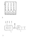
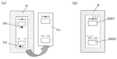
以下、本発明に係る照明制御システムの実施の形態3に関して図6を参照して説明する。図6(a)に示すように、アドレス設定器11を用いてスイッチ操作器6の4つのスイッチ部SW1〜SW4に間引き制御用のパターンアドレスを設定する。この際、図6(b)のテーブル12に示すように、SW1に「P−1」、SW2に「P−5」、SW3に「P−9」、SW4に「P−13」を設定する。
(Embodiment 3)
Hereinafter, Embodiment 3 of the illumination control system according to the present invention will be described with reference to FIG. As shown in FIG. 6A, pattern addresses for thinning control are set in the four switch sections SW1 to SW4 of the switch operating device 6 using the address setting device 11. At this time, as shown in the table 12 of FIG. 6B, “P-1” is set in SW1, “P-5” in SW2, “P-9” in SW3, and “P-13” in SW4. .

スイッチ操作器6は、各スイッチSW1〜SW4に設定されたパターンアドレスと、「パターンアドレス+1」、「パターンアドレス+2」、「パターンアドレス+3」とを一組として固定する。すなわち、スイッチ操作器6は、間引き制御用スイッチSW1〜SW4の各々が押下される度に、SW1ではP1→P2→P3→P4→P1・・・、SW2ではP5→P6→P7→P8→P5・・・、SW3ではP9→P10→P11→P12→P9・・・、SW4ではP13→P14→P15→P16→P13・・・の順番にパターンアドレスを変更する。このことで、スイッチ操作器6は、順に間引き制御のためのパターンアドレス制御を行い、照明制御システム1は照明負荷9の間引き制御を実現できる。なお、このようなパターンアドレスの変更を伝送ユニット2で自動的に行ってもよい。   The switch operator 6 fixes the pattern address set to each of the switches SW1 to SW4 and “pattern address + 1”, “pattern address + 2”, and “pattern address + 3” as a set. That is, every time each of the thinning control switches SW1 to SW4 is pressed, the switch operating unit 6 is P1 → P2 → P3 → P4 → P1... In SW1, and P5 → P6 → P7 → P8 → P5 in SW2. ..., the pattern address is changed in the order of P9.fwdarw.P10.fwdarw.P11.fwdarw.P9... For SW3, and P13.fwdarw.P14.fwdarw.P15.fwdarw.P16.fwdarw.P13. Accordingly, the switch operating device 6 sequentially performs pattern address control for thinning control, and the lighting control system 1 can realize thinning control of the lighting load 9. Note that such a change of the pattern address may be automatically performed by the transmission unit 2.

このため、本実施の形態3においては、スイッチ操作器6にディップスイッチ等を設ける必要がなく、既存のスイッチ操作器6の各SWに複数のパターンアドレスを付与できる。また、従来のアドレス設定器11を用いてスイッチ操作器6のアドレス設定ができる。   For this reason, in this Embodiment 3, it is not necessary to provide a dip switch etc. in the switch operating device 6, and a plurality of pattern addresses can be given to each SW of the existing switch operating device 6. Further, the address setting of the switch operating device 6 can be performed using the conventional address setting device 11.

(第1の変形例)
本実施の形態3の第1の変形例について、図7を参照して説明する。上記実施の形態3においては、スイッチ操作器6の各スイッチSW1〜SW4にパターンアドレスを一つ設定するだけで各SWに4つのパターンアドレスが制御に用いられるため、使用されるパターンアドレスが重複する可能性がある。
(First modification)
A first modification of the third embodiment will be described with reference to FIG. In the third embodiment, since only one pattern address is set for each switch SW1 to SW4 of the switch operating device 6 and four pattern addresses are used for control in each SW, the pattern addresses used overlap. there is a possibility.

従って、本変形例では、図7(a)に示すように、スイッチ操作器6のスイッチに2つのグループアドレスを設定する。具体的には、図7(b)のテーブル71に示すようにスイッチ操作器6のSW1の一度目のONアドレスは「G1」、SW1の二度目のONアドレスは「G2」、SW2の一度目のONアドレスは「G1,G2」、SW2の二度目のONアドレスは「なし」と設定する。   Therefore, in this modification, as shown in FIG. 7A, two group addresses are set in the switch of the switch operating device 6. Specifically, as shown in the table 71 of FIG. 7B, the first ON address of SW1 of the switch operating device 6 is “G1”, the second ON address of SW1 is “G2”, and the first ON address of SW2. Is set to “G1, G2”, and the second ON address of SW2 is set to “none”.

これにより、スイッチ操作器6に新たにディップスイッチ等を設ける必要もなく、既存のスイッチ操作器6を用いて図7(a)に示す照明負荷9の間引き点灯制御を実現できる。また、従来のアドレス設定器を用いて、パターンアドレスの重複使用が防ぎながらスイッチ操作器6のアドレス設定ができる。   Thereby, it is not necessary to newly provide a dip switch or the like in the switch operating device 6, and the thinning-out lighting control of the illumination load 9 shown in FIG. 7A can be realized using the existing switch operating device 6. Further, by using a conventional address setting device, it is possible to set the address of the switch operating device 6 while preventing duplicate use of pattern addresses.

(実施の形態4)
以下、本発明に係る照明制御システムの実施の形態4に関して図8を参照して説明する。本実施の形態4では、照明負荷9の間引き点灯制御を行う場合のスイッチ操作器6,7の操作面の表示に関して説明する。
(Embodiment 4)
Hereinafter, Embodiment 4 of the illumination control system according to the present invention will be described with reference to FIG. In the fourth embodiment, the display on the operation surface of the switch operating devices 6 and 7 when performing the thinning-out lighting control of the illumination load 9 will be described.

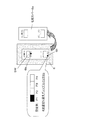
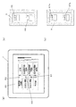
図8(a)に示す場合、液晶付スイッチ操作器7の液晶表示部60において、表示スイッチ周囲の全点灯時の赤表示の領域部(61)を上下に2分して、間引き制御状態であるかどうかを表示する。具体的には、間引き点灯状態のシーンが2つの場合、一方の照明負荷9群が間引き制御状態である時に上領域側の赤表示(62)を行い、他方の照明負荷9群が間引き制御状態であるときに下領域側の赤表示(63)を行う。   In the case shown in FIG. 8 (a), in the liquid crystal display unit 60 of the switch operating unit with liquid crystal 7, the area (61) of red display at the time of all lighting around the display switch is vertically divided into two parts in the thinning control state. Displays whether there is. Specifically, when there are two scenes in the thinned-out lighting state, when one lighting load 9 group is in the thinning-out control state, red display (62) on the upper area side is performed, and the other lighting load 9 group is in the thinning-out control state. Is displayed in red on the lower area side (63).

この表示により、照明負荷9の間引き点灯状態を液晶付スイッチ操作器7の液晶表示部61で確認でき、ユーザが一目でその時点での照明負荷9の全体の制御状態を把握できる。また、ユーザは照明制御システム1の異常状態もいち早く検知することができる。   With this display, the thinning-out lighting state of the lighting load 9 can be confirmed on the liquid crystal display unit 61 of the switch operating unit with liquid crystal 7, and the user can grasp the entire control state of the lighting load 9 at a glance. Further, the user can quickly detect an abnormal state of the lighting control system 1.

図8(b)及び図8(c)にはスイッチ操作器6がLED表示部を有する場合であり、既存のスイッチ操作器6として最も汎用されている製品である。図8(b)に示す場合には、従来のON時の赤点灯部分を2色発光LED(例えば赤/橙)とし、間引き点灯(橙色)と全点灯(赤色)とでLED表示色(65)を切り替える。この場合、OFF時には従来通り緑表示(66)とする。   FIG. 8B and FIG. 8C show the case where the switch operating device 6 has an LED display unit, which is the most widely used product as the existing switch operating device 6. In the case shown in FIG. 8B, the conventional red lighting portion when ON is a two-color light emitting LED (for example, red / orange), and the LED display color (65) is thinned (orange) and fully lit (red). ). In this case, when OFF, the green display (66) is used as usual.

図8(c)に示す場合には、間引き制御を表示するため上下2つのLED表示部67を新たに追加する。例えば、照明負荷群AのみをON時の間引き点灯では、表示部67の上側のLED67aのみを橙点灯し、別の照明負荷群BのみをON時の間引き点灯では、表示部67の下側のLED67bのみを橙点灯する。この構成により、従来のスイッチ操作器6において、ユーザがその時点での照明負荷9の間引き点灯状態を視覚的に把握できるようになる。   In the case shown in FIG. 8C, two upper and lower LED display portions 67 are newly added to display the thinning control. For example, when only the illumination load group A is turned on when the light is turned on, only the upper LED 67a of the display unit 67 is lit in orange. When only another light load group B is turned on when the light is turned on, only the lower LED 67b of the display unit 67 is turned on. Lights up orange. With this configuration, in the conventional switch operating device 6, the user can visually grasp the thinning-out lighting state of the lighting load 9 at that time.

(第1の変形例)
本実施の形態4の第1の変形例について、図9を参照して説明する。本変形例は、ユーザに対してある程度の間引き制御を行う照明負荷9のフレキシビリティを持たせることで、照明負荷9の明るさに合わせた延命制御を行うものである。
(First modification)
A first modification of the fourth embodiment will be described with reference to FIG. In this modification, life extension control is performed in accordance with the brightness of the lighting load 9 by giving the user the flexibility of the lighting load 9 that performs thinning control to some extent.

図9に示すように、スイッチ操作器6は、スイッチ操作器6の化粧カバー6aを取り外した表面からは見えない部分に2極のディップスイッチ6cを備える。そして、例えば、このディップスイッチ6cの2極の内の右側に設定したスイッチSW1の操作を行った場合は、照明負荷群Aを点灯し、再度押下するとOFF制御する。ディップスイッチ6cの2極の内の左側に設定したスイッチSW2の操作を行った場合は、照明負荷群Bを点灯して再度押下するとOFF制御する。   As shown in FIG. 9, the switch operator 6 includes a two-pole dip switch 6 c in a portion that cannot be seen from the surface of the switch operator 6 from which the decorative cover 6 a is removed. For example, when the switch SW1 set on the right side of the two poles of the dip switch 6c is operated, the illumination load group A is turned on, and when it is pressed again, OFF control is performed. When the switch SW2 set on the left side of the two poles of the dip switch 6c is operated, the illumination load group B is turned on and is turned off when pressed again.

この構成により、間引き点灯時に点灯させる照明負荷9を、ディップスイッチ6cを用いてユーザが意図的に選択できる。従って、複数の照明負荷9間で経年変化などにより明るさにばらつきがある場合など、間引き制御する照明負荷9をユーザが選択することで寿命を均一化することができ、また点灯中の明るさのばらつきによる違和感をなくすことができる。   With this configuration, the user can intentionally select the illumination load 9 to be lit at the time of thinning lighting using the dip switch 6c. Accordingly, when the brightness varies due to secular change among the plurality of lighting loads 9, the life can be made uniform by the user selecting the lighting load 9 to be thinned out, and the brightness during lighting. Discomfort due to variations in the quality can be eliminated.

(第2の変形例)
本実施の形態4の第2の変形例について、図10を参照して説明する。本変形例では、図10に示すように、ディップスイッチ6dを3極にしている。横並びのディップスイッチ6dを想定した場合に、左端/右端に設定したときの動作は該変形例1のディップスイッチ6cと同様であるが、真ん中に設定した場合にスイッチ操作を行うと全点灯及び全消灯を繰り返すように設定できる。この構成により、スイッチ操作器6の1つのスイッチSWで、全点灯制御、間引き点灯制御、全消灯制御を実現することができ、かつ省スペースなスイッチ操作器6とできる。なお、本発明は、上記実施の形態の構成に限られず、発明の趣旨を変更しない範囲で種々の変形が可能である。
(Second modification)
A second modification of the fourth embodiment will be described with reference to FIG. In this modification, as shown in FIG. 10, the dip switch 6d has three poles. Assuming a side-by-side dip switch 6d, the operation when set to the left end / right end is the same as that of the dip switch 6c of the first modification. However, when the switch is operated in the middle, all lighting and all Can be set to turn off repeatedly. With this configuration, it is possible to realize full lighting control, thinning lighting control, and full light extinction control with one switch SW of the switch operating device 6, and a space saving switch operating device 6 can be provided. The present invention is not limited to the configuration of the embodiment described above, and various modifications can be made without departing from the spirit of the invention.

1 照明制御システム
2 伝送ユニット
3 リレー制御端末器(制御端末器)
4 リモコンリレー
5 リモコントランス
6 スイッチ操作器(負荷操作器)
6a 化粧カバー
6b,6c,6d ディップスイッチ
7 液晶付スイッチ操作器(負荷操作器)
8 照度センサ
9 照明負荷
11 アドレス設定器
61 液晶表示部
SW1,SW2,SW3,SW4 スイッチ(スイッチ手段)
1 Lighting Control System 2 Transmission Unit 3 Relay Control Terminal (Control Terminal)
4 Remote control relay 5 Remote control transformer 6 Switch operation device (load operation device)
6a Cosmetic cover 6b, 6c, 6d Dip switch 7 Switch operator with liquid crystal (load operator)
8 Illuminance sensor 9 Illumination load 11 Address setter 61 Liquid crystal display SW1, SW2, SW3, SW4 Switch (switch means)

Claims (5)

制御対象となる照明負荷の状態を変化させるために操作され、該操作に応じて信号を出力する負荷操作器と、前記負荷操作器の制御対象となる照明負荷を制御する制御端末器と、信号線を介して前記制御端末器及び前記負荷操作器と接続され伝送信号を送受信する伝送ユニットと、を備える照明制御システムにおいて、
前記負荷操作器は、
複数の照明負荷から一部の照明負荷の点灯を省く間引き制御する際、点灯させるごとに点灯する照明負荷が入れ替わるようにアドレス設定されたスイッチ手段と、
前記スイッチ手段が押下された場合、前記アドレスを含む制御信号を前記伝送ユニットに送信する送受信手段と、を備え、
前記伝送ユニットは、
前記制御信号に含まれるアドレスに対応する照明負荷を間引き制御するための制御信号を前記制御端末器に送信する制御手段を備えた、ことを特徴とする照明制御システム。
A load operating device that is operated to change the state of the lighting load to be controlled and outputs a signal in response to the operation, a control terminal that controls the lighting load to be controlled by the load operating device, and a signal In a lighting control system comprising: a transmission unit that is connected to the control terminal and the load controller via a line and transmits and receives a transmission signal;
The load controller is
When performing thinning out control that eliminates lighting of some lighting loads from a plurality of lighting loads, switch means that is addressed so that the lighting loads that are turned on each time it is turned on, and
A transmission / reception unit that transmits a control signal including the address to the transmission unit when the switch unit is pressed;
The transmission unit is
An illumination control system comprising: control means for transmitting to the control terminal a control signal for performing thinning control of an illumination load corresponding to an address included in the control signal.
前記アドレスには、間引き制御において一部の照明負荷を点灯させるパターンアドレス、間引き制御において前記一部の照明負荷以外の照明負荷を点灯させるパターンアドレス、全ての照明負荷を点灯させるパターンアドレス、及び全ての照明負荷を消灯させるパターンアドレスが含まれる、ことを特徴とする請求項1記載の照明制御システム。   The address includes a pattern address for lighting a part of the lighting load in the thinning control, a pattern address for lighting a lighting load other than the part of the lighting load in the thinning control, a pattern address for lighting all the lighting loads, and all The lighting control system according to claim 1, further comprising a pattern address for turning off the lighting load of the lighting device. 前記負荷操作器は、照明負荷の点灯状態を表示する表示部を有し、
前記表示部は、間引き点灯状態と、そうでない状態とで表示色又は表示領域を異ならせた、ことを特徴とする請求項1又は2に記載の照明制御システム。
The load operating device has a display unit for displaying a lighting state of a lighting load,
The illumination control system according to claim 1, wherein the display unit has a display color or a display area that is different between a thinned-out lighting state and a non-thinning state.
前記表示部は、液晶表示部であり、前記間引き点灯状態においては、照明負荷の全点灯時において所定色で表示される前記液晶表示部の領域の半分の領域を前記所定色で表示する、ことを特徴とする請求項3記載の照明制御システム。   The display unit is a liquid crystal display unit, and in the thinned-out lighting state, half the area of the liquid crystal display unit displayed in a predetermined color when the lighting load is fully lit is displayed in the predetermined color. The lighting control system according to claim 3. 前記表示部は、LED表示部であり、前記間引き点灯状態においては、照明負荷の全点灯時において所定色で表示される前記LED表示部を他の色で表示する、ことを特徴とする請求項3記載の照明制御システム。   The display unit is an LED display unit, and in the thinned lighting state, the LED display unit displayed in a predetermined color when the lighting load is fully lit is displayed in another color. 3. The lighting control system according to 3.
JP2011062989A 2011-03-22 2011-03-22 Illumination control system Withdrawn JP2012199099A (en)

Priority Applications (1)

Application Number Priority Date Filing Date Title
JP2011062989A JP2012199099A (en) 2011-03-22 2011-03-22 Illumination control system

Applications Claiming Priority (1)

Application Number Priority Date Filing Date Title
JP2011062989A JP2012199099A (en) 2011-03-22 2011-03-22 Illumination control system

Publications (1)

Publication Number Publication Date
JP2012199099A true JP2012199099A (en) 2012-10-18

Family

ID=47181124

Family Applications (1)

Application Number Title Priority Date Filing Date
JP2011062989A Withdrawn JP2012199099A (en) 2011-03-22 2011-03-22 Illumination control system

Country Status (1)

Country Link
JP (1) JP2012199099A (en)

Cited By (1)

* Cited by examiner, † Cited by third party
Publication number Priority date Publication date Assignee Title
WO2015013375A1 (en) * 2013-07-26 2015-01-29 3M Innovative Properties Company Augmented reality graphical user interface for network controlled lighting systems

Cited By (1)

* Cited by examiner, † Cited by third party
Publication number Priority date Publication date Assignee Title
WO2015013375A1 (en) * 2013-07-26 2015-01-29 3M Innovative Properties Company Augmented reality graphical user interface for network controlled lighting systems

Similar Documents

Publication Publication Date Title
JP5371290B2 (en) Lighting control system
KR100313553B1 (en) Remote supervisory control system
JP2010198877A (en) Lighting control system
JP2009283183A (en) Illumination control system
JP2017123319A (en) Illumination system and controller
JP5299677B2 (en) Lighting control system
JP2010080102A (en) Lighting control system
JP6069864B2 (en) Monitoring terminal and lighting control system using the monitoring terminal
CN104080242A (en) Lighting control system and lighting control method
KR101665559B1 (en) Method and apparatus for controlling LED lights
TWI574562B (en) Load control system
KR101422895B1 (en) Illumination control terminal and illumination control system
KR101354545B1 (en) Illuminance sensor setting device
JP2012199099A (en) Illumination control system
JP6108799B2 (en) Lighting control system
JP6369728B2 (en) Monitoring terminal and lighting control system using the monitoring terminal
JP4002491B2 (en) Remote control transmitter for lighting
JP6210357B2 (en) LED lighting fixture control device
WO2015119292A1 (en) Light adjusting system and large-scale light adjusting system
CN101672431B (en) Group control type illumination control system
JP2002110369A (en) Illumination device
RU2325704C2 (en) Method of three-section road traffic light operation
JP4976580B1 (en) Switcher and display device
JP5276839B2 (en) Input terminal
JP4506752B2 (en) Lighting control system

Legal Events

Date Code Title Description
A300 Application deemed to be withdrawn because no request for examination was validly filed

Free format text: JAPANESE INTERMEDIATE CODE: A300

Effective date: 20140603