JP2012196016A - Power supply management system, portable terminal, control method for power supply management system, and program thereof - Google Patents
Power supply management system, portable terminal, control method for power supply management system, and program thereof Download PDFInfo
- Publication number
- JP2012196016A JP2012196016A JP2011056761A JP2011056761A JP2012196016A JP 2012196016 A JP2012196016 A JP 2012196016A JP 2011056761 A JP2011056761 A JP 2011056761A JP 2011056761 A JP2011056761 A JP 2011056761A JP 2012196016 A JP2012196016 A JP 2012196016A
- Authority
- JP
- Japan
- Prior art keywords
- wireless lan
- mobile terminal
- management system
- power
- power management
- Prior art date
- Legal status (The legal status is an assumption and is not a legal conclusion. Google has not performed a legal analysis and makes no representation as to the accuracy of the status listed.)
- Withdrawn
Links
Images


Classifications
-
- Y—GENERAL TAGGING OF NEW TECHNOLOGICAL DEVELOPMENTS; GENERAL TAGGING OF CROSS-SECTIONAL TECHNOLOGIES SPANNING OVER SEVERAL SECTIONS OF THE IPC; TECHNICAL SUBJECTS COVERED BY FORMER USPC CROSS-REFERENCE ART COLLECTIONS [XRACs] AND DIGESTS
- Y02—TECHNOLOGIES OR APPLICATIONS FOR MITIGATION OR ADAPTATION AGAINST CLIMATE CHANGE
- Y02B—CLIMATE CHANGE MITIGATION TECHNOLOGIES RELATED TO BUILDINGS, e.g. HOUSING, HOUSE APPLIANCES OR RELATED END-USER APPLICATIONS
- Y02B70/00—Technologies for an efficient end-user side electric power management and consumption
- Y02B70/30—Systems integrating technologies related to power network operation and communication or information technologies for improving the carbon footprint of the management of residential or tertiary loads, i.e. smart grids as climate change mitigation technology in the buildings sector, including also the last stages of power distribution and the control, monitoring or operating management systems at local level
-
- Y—GENERAL TAGGING OF NEW TECHNOLOGICAL DEVELOPMENTS; GENERAL TAGGING OF CROSS-SECTIONAL TECHNOLOGIES SPANNING OVER SEVERAL SECTIONS OF THE IPC; TECHNICAL SUBJECTS COVERED BY FORMER USPC CROSS-REFERENCE ART COLLECTIONS [XRACs] AND DIGESTS
- Y02—TECHNOLOGIES OR APPLICATIONS FOR MITIGATION OR ADAPTATION AGAINST CLIMATE CHANGE
- Y02B—CLIMATE CHANGE MITIGATION TECHNOLOGIES RELATED TO BUILDINGS, e.g. HOUSING, HOUSE APPLIANCES OR RELATED END-USER APPLICATIONS
- Y02B90/00—Enabling technologies or technologies with a potential or indirect contribution to GHG emissions mitigation
- Y02B90/20—Smart grids as enabling technology in buildings sector
-
- Y—GENERAL TAGGING OF NEW TECHNOLOGICAL DEVELOPMENTS; GENERAL TAGGING OF CROSS-SECTIONAL TECHNOLOGIES SPANNING OVER SEVERAL SECTIONS OF THE IPC; TECHNICAL SUBJECTS COVERED BY FORMER USPC CROSS-REFERENCE ART COLLECTIONS [XRACs] AND DIGESTS
- Y04—INFORMATION OR COMMUNICATION TECHNOLOGIES HAVING AN IMPACT ON OTHER TECHNOLOGY AREAS
- Y04S—SYSTEMS INTEGRATING TECHNOLOGIES RELATED TO POWER NETWORK OPERATION, COMMUNICATION OR INFORMATION TECHNOLOGIES FOR IMPROVING THE ELECTRICAL POWER GENERATION, TRANSMISSION, DISTRIBUTION, MANAGEMENT OR USAGE, i.e. SMART GRIDS
- Y04S20/00—Management or operation of end-user stationary applications or the last stages of power distribution; Controlling, monitoring or operating thereof
- Y04S20/20—End-user application control systems
- Y04S20/242—Home appliances
-
- Y—GENERAL TAGGING OF NEW TECHNOLOGICAL DEVELOPMENTS; GENERAL TAGGING OF CROSS-SECTIONAL TECHNOLOGIES SPANNING OVER SEVERAL SECTIONS OF THE IPC; TECHNICAL SUBJECTS COVERED BY FORMER USPC CROSS-REFERENCE ART COLLECTIONS [XRACs] AND DIGESTS
- Y04—INFORMATION OR COMMUNICATION TECHNOLOGIES HAVING AN IMPACT ON OTHER TECHNOLOGY AREAS
- Y04S—SYSTEMS INTEGRATING TECHNOLOGIES RELATED TO POWER NETWORK OPERATION, COMMUNICATION OR INFORMATION TECHNOLOGIES FOR IMPROVING THE ELECTRICAL POWER GENERATION, TRANSMISSION, DISTRIBUTION, MANAGEMENT OR USAGE, i.e. SMART GRIDS
- Y04S40/00—Systems for electrical power generation, transmission, distribution or end-user application management characterised by the use of communication or information technologies, or communication or information technology specific aspects supporting them
- Y04S40/12—Systems for electrical power generation, transmission, distribution or end-user application management characterised by the use of communication or information technologies, or communication or information technology specific aspects supporting them characterised by data transport means between the monitoring, controlling or managing units and monitored, controlled or operated electrical equipment
- Y04S40/124—Systems for electrical power generation, transmission, distribution or end-user application management characterised by the use of communication or information technologies, or communication or information technology specific aspects supporting them characterised by data transport means between the monitoring, controlling or managing units and monitored, controlled or operated electrical equipment using wired telecommunication networks or data transmission busses
Abstract
Description
本発明は、電源管理システム、携帯端末、電源管理システムの制御方法及びそのプログラムに関する。 The present invention relates to a power management system, a portable terminal, a power management system control method, and a program thereof.
家庭内では、多くの家庭用電化製品(以下、電化製品)が用いられている。また近年では、これらの電化製品の利便性の向上が図られている。例えば、外出先から電化製品の動作状態を管理し遠隔操作を行うシステムが提案されており、このシステムを利用することによって、帰宅前から自宅の照明を点灯しておくことや、エアコンを用いて部屋の温度をあらかじめ調整することが可能である。 Many household appliances (hereinafter, “electric appliances”) are used in the home. In recent years, the convenience of these electric appliances has been improved. For example, a system that manages the operating state of electrical appliances from a remote location and performs remote operation has been proposed. By using this system, lighting of the home can be turned on before returning home, or an air conditioner can be used. It is possible to adjust the room temperature in advance.
特許文献1には、特定の電化製品に絞って電源状態を使用者に知らしめることにより、外出先から電化製品の電源を誤って操作することなく、外出時に電化製品の電源状態の確認を失念しにくい、電化製品の電源管理装置が開示されている。より具体的には、この電源管理装置は、携帯電話からの要求又は玄関扉の鍵の施錠が行われた場合に、あらかじめ監視対象として指定した電化製品の電源状態を記述した電子メールを、携帯電話に送信することで、電化製品の電源状態を使用者に通知する。
特許文献2には、電源操作内容に応じた宛先メールアドレスを設定してメール送信を行うことで、電子メールのサブジェクトやテキスト部に制御コードを入力することなく、電源操作を行う電源制御装置が開示されている。
特許文献3には、家庭内の使用電力量が許容量を超えてしまった場合に、あらかじめ定めた優先順位に従って電化製品のブレーカーをオフにすることで、全ての電化製品が強制的に電源オフされるのを回避する、電化製品の電源管理システムが開示されている。 In Patent Document 3, when the power consumption in the home exceeds the allowable amount, all the appliances are forcibly turned off by turning off the breakers of the appliances according to a predetermined priority order. A power management system for electrical appliances that avoids this is disclosed.
特許文献4には、電源コンセント口からの電源供給のON/OFF制御可能とし、電力の消費を抑制可能とする一方、電源コンセント口から電源がOFFにされている場合でも、遠隔位置から電源をONに制御することができる電源管理システムが開示されている。 In Patent Document 4, it is possible to control ON / OFF of power supply from a power outlet, and it is possible to suppress power consumption. On the other hand, even when the power is turned off from the power outlet, A power management system that can be controlled to ON is disclosed.
しかしながら、特許文献1に開示されている電源管理装置では、使用者の外出認識を鍵施錠に基づいて行う。したがって、鍵施錠が必要のない建物では、特許文献1に開示されている電源管理装置を適用することができなかった。また、使用者が鍵施錠を行わずに外出した場合には、電源管理装置は使用者の外出認識を行うことができないため、使用者に電化製品の電源の切り忘れを知らしめることができなかった。
However, the power management device disclosed in
本発明はこのような問題点を解決するためになされたものであり、鍵施錠によらずに、使用者に電化製品の電源状態を知らしめる、電源管理システム、携帯端末、電源管理システムの制御方法及びそのプログラムを提供することを目的とする。 The present invention has been made to solve such problems, and controls the power management system, the portable terminal, and the power management system to notify the user of the power state of the electrical appliance without using the key lock. It is an object to provide a method and a program thereof.
本発明にかかる電源管理システムは、電化製品の電源状態を取得する監視部と、携帯端末が無線LANの通信圏外であることを検出する検出部と、前記携帯端末との通信を行う通信部と、を備え、前記検出部により前記携帯端末が前記無線LANの通信圏外であると検出されたことを契機として、前記通信部は、前記監視部で取得された前記電化製品の電源状態を前記携帯端末に通知する。 A power management system according to the present invention includes a monitoring unit that acquires a power state of an electrical appliance, a detection unit that detects that the mobile terminal is out of a communication range of a wireless LAN, and a communication unit that performs communication with the mobile terminal. , And the communication unit detects the power state of the appliance acquired by the monitoring unit when the detection unit detects that the portable terminal is out of the communication range of the wireless LAN. Notify the terminal.
また、本発明にかかる携帯端末は、無線LANの通信圏外となったことを契機に、電源管理システムに対して電化製品の電源状態の情報の取得要求を行い、前記電源管理システムから前記電化製品の電源状態の情報を取得する。 In addition, the mobile terminal according to the present invention requests the power management system to acquire information on the power state of the electrical appliance when the mobile terminal is out of the communication range of the wireless LAN, and the electrical appliance from the power management system Get power status information for.
また、本発明にかかる電源管理システムの制御方法は、電化製品の電源状態を取得し、携帯端末が無線LANの通信圏外であることを検出し、前記携帯端末が前記無線LANの通信圏外であると検出されたことを契機として、取得された前記電化製品の電源状態を前記携帯端末に送信する。 Also, the control method of the power management system according to the present invention acquires the power state of the electrical appliance, detects that the mobile terminal is out of the wireless LAN communication range, and the mobile terminal is out of the wireless LAN communication range. The detected power state of the electrical appliance is transmitted to the mobile terminal.
また、本発明にかかるプログラムは、電化製品の電源状態を取得し、携帯端末が無線LANの通信圏外であることを検出し、前記携帯端末が前記無線LANの通信圏外であると検出されたことを契機として、取得された前記電化製品の電源状態を前記携帯端末に送信することを、コンピュータに実行させる。 Further, the program according to the present invention acquires the power state of the electrical appliance, detects that the mobile terminal is out of the wireless LAN communication range, and detects that the mobile terminal is out of the wireless LAN communication range. As a trigger, the computer is caused to transmit the acquired power state of the appliance to the portable terminal.
鍵施錠によらずに、使用者に電化製品の電源状態を知らしめることが可能な電源管理システム、携帯端末、電源管理システムの制御方法及びそのプログラムを提供できる。 A power management system, a portable terminal, a control method for the power management system, and a program for the power management system that can inform the user of the power state of the electrical appliance without using the key lock can be provided.
実施の形態1
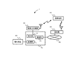
以下、図面を参照して本発明の実施の形態について説明する。図1は、本実施の形態に係る電源管理システムを用いて、電化製品を管理するための構成を示した図である。
Embodiments of the present invention will be described below with reference to the drawings. FIG. 1 is a diagram illustrating a configuration for managing electrical appliances using the power management system according to the present embodiment.
通信システム1は、電源管理システム10、電化製品20、無線LAN機器30、公衆網40、基地局50、及び携帯端末60を備える。
The
電源管理システム10は、監視部11、検出部12、及び通信部13を有する。電源管理システム10は、電化製品20、無線LAN機器30、及び公衆網40に接続されている。電源管理システム10は、電化製品20の電源状態を制御する機能を有する。
The power management system 10 includes a
監視部11は、電化製品20の電源状態を監視する。典型的には、監視部11は、電化製品20の電源のON/OFF状態を監視する。監視部11による監視対象とされる電化製品20の電源状態は、電源のON/OFF状態に限られない。例えば、監視対象とされる電源状態は、電化製品に搭載されているバッテリの残量、消費電力量、及び消費電力に影響を与えるその他のパラメータのうち少なくとも1つを含んでもよい。消費電力に影響を与えるパラメータは、CPU(Central Processing Unit)の負荷、データパケットの送受信量、又は電化製品20の内部温度等である。
なお監視部11は、電化製品20の動作の強弱状態やタイマーの設定状態を監視しても良い。例えば、電化製品20がエアコンである場合には、強風・弱風の動作を監視しても良い。
The
Note that the
検出部12は、携帯端末60が無線LAN機器30の通信圏外(エリア外)であることを検出する。無線LAN機器30の通信圏外であることを検出する方法は問わない。
例えば検出部12は、無線LAN機器30で通信を行っているIPアドレスを監視し、携帯端末60のIPアドレスからのデータ送受信の有無に基づいて、携帯端末60の通信圏外であるか否かを検出しても良い。また例えば、検出部12は、基地局50と携帯端末60の通信に関する情報を基地局50から受信することにより、携帯端末60の位置を把握し、携帯端末60が無線LAN機器30の通信圏外にあることを検出しても良い。また例えば、検出部12は、携帯端末60が無線LAN機器30の通信圏外となった場合に、携帯端末60が公衆網40を介して送信した情報を受信することで、携帯端末60が無線LAN機器30の通信圏外にあることを検出しても良い。
The
For example, the
通信部13は、電化製品20の電源状態を携帯端末60に通知する機能を有する。典型的には通信部13は、公衆網40を介して携帯端末60に、電化製品20の電源状態を記載した電子メール(以下、メール)の送信を行う。
The
なお、電源管理システム10の動作は、電源管理システム10に設けられたROMに記憶されているプログラムに基づいて、電源管理システム10に設けられたCPUが演算処理を行うことにより実現できる。 Note that the operation of the power management system 10 can be realized by a CPU provided in the power management system 10 performing arithmetic processing based on a program stored in a ROM provided in the power management system 10.
電化製品20は、典型的には、家屋内に備え付けられた各種の電化製品である。電化製品20は、電源管理システム10により、電源状態の監視や制御が行われる。例えば電化製品20は、ステレオ、ビデオデッキ、テレビ、電気ストーブ、アイロン、ドライヤー、洗濯機などである。さらに、電化製品20には、無線LAN機器30が含まれていても良い。電化製品20は、これらのものに限られない。
各種の電化製品20は、電源管理システム10と通信可能に接続されている。電源管理システム10と電化製品20の間は、例えば、有線LAN(Local Area Network)、無線LAN、又は電力線通信によって接続すればよい。
The
Various
無線LAN機器30は、無線LAN機器30を中心とした通信圏内(エリア内)の携帯端末60と通信を行う。無線LAN機器30は、携帯端末60が通信圏内に存在しているか否かを認識する手段を有するのが好ましい。
なお図1において、無線LAN機器30は、電源管理システム10と別個の機器として記載しているが、電源管理システム10と一体の機器であっても良い。
The
In FIG. 1, the
公衆網40は、電源管理システム10と携帯端末60の情報を伝達する経路となるネットワークである。典型的には、公衆網40は、TCP/IPプロトコルによって結ばれているインターネット網である。
The
基地局50は、公衆網40の末端であり、携帯端末60と無線通信を行う通信装置を備える。
The
携帯端末60は、例えば、携帯電話端末、スマートフォン、タブレットコンピュータ、ノートPC(Personal Computer)等である。携帯端末60は、基地局50を介して公衆網40に接続する。さらに携帯端末60は、無線LAN機器30の構築するエリア内において、無線LAN機器30と通信を行う。
The
次に、電源管理システム10を用いて、使用者が電化製品20の電源状態を管理する手順について説明する。
Next, a procedure for the user to manage the power state of the
まず、検出部12は、携帯端末60の位置が、無線LAN機器30の通信圏外であるか否かを検出する。
例えば、検出部12は、無線LAN機器30で通信を行っているIPアドレスを監視し、携帯端末60のIPアドレスからの問い合わせが無ければ、携帯端末60は通信圏外であると判定する。
また例えば、検出部12は、基地局50と携帯端末60の通信に関する情報を基地局50から受信し、基地局50の位置情報等に基づいて携帯端末60の位置を把握し、携帯端末60が無線LAN機器30の通信圏外にあると判定する。
また例えば、携帯端末60は、無線LAN機器30の通信圏外となった場合に公衆網40を介して情報を送信し、検出部12はこの情報を受信した場合に携帯端末60が無線LAN機器30の通信圏外にあると判定する。携帯端末60から検出部12への情報の送信には、例えばメールを用いる。
First, the
For example, the
Further, for example, the
For example, when the
携帯端末60が無線LAN機器30の通信圏外であると判定された場合には、監視部11は、電源管理システム10に接続している電化製品20の電源状態を取得する。
その後、通信部13は、監視部11で取得された電化製品20の電源状態を、公衆網40を介して携帯端末60に送信する。これにより使用者は、電化製品20の電源状態を確認することができる。
When it is determined that the
Thereafter, the
携帯端末60が無線LAN機器30の通信圏内であると判定された場合には、検出部12は、携帯端末60が無線LAN機器30の通信圏外であるか否かの判定を、繰り返し行う。
When it is determined that the
なお、使用者の携帯端末60の操作により、携帯端末60から電源管理システム10に、電化製品20の電源状態の情報を取得したい旨の指示の情報が送信された場合には、監視部11は電化製品20の電源状態の情報を取得し、通信部13は、監視部11で取得された電化製品20の電源状態を、携帯端末60に送信する。
さらに、使用者による携帯端末60の操作により、携帯端末60から電源管理システム10に電化製品20の電源状態の変更を指示する情報が送信された場合には、電源管理システム10は受信した変更を指示する情報に基づいて、電化製品20の電源状態を変更する。
In addition, when the user's operation of the
Furthermore, when the user operates the
このとき、携帯端末60が無線LAN機器30の通信圏外にある場合には、携帯端末60は公衆網40を介して情報を送信する。携帯端末60が無線LAN機器の通信圏内にある場合には、携帯端末60は公衆網40を介して情報を送信しても良く、無線LAN機器30との直接の通信により情報を送信しても良い。
At this time, when the
これにより、電源管理システム10は、無線LAN機器30の圏外認識に基づいて使用者の外出認識を行い、使用者に電化製品20の電源状態を通知することができる。
本実施の形態によれば、電源管理システム10に鍵施錠を認識させる必要が無いため、鍵施錠を認識させるように施設を改造する必要が無く、また、鍵施錠ができない施設であっても使用が可能である。さらに電源管理システム10は、使用者が、鍵施錠を必要とする施設の鍵施錠を忘れた場合であっても、電化製品20の電源状態を通知することができる。
Thereby, the power management system 10 can recognize the user's going out based on the out-of-service recognition of the
According to the present embodiment, since it is not necessary to make the power management system 10 recognize the key locking, there is no need to modify the facility so that the key locking can be recognized, and even the facility where the key locking cannot be performed is used. Is possible. Further, the power management system 10 can notify the power state of the
実施の形態2
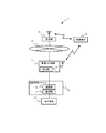
図2は、本実施の形態に係る通信システム2を用いて、電化製品20を管理するための構成を示した図である。なお、実施の形態1で示した構成物品と同様の機能を有する構成物品については、同一の符号を付し、説明を省略する。
FIG. 2 is a diagram showing a configuration for managing
通信システム2は、電源管理システム15、電化製品20、無線LAN機器31、公衆網40、基地局50、及び携帯端末60を備える。
The
電源管理システム15は、接続されている電化製品20の電源状態を監視する監視部11と、無線LAN機器30との通信を行う通信部13を備える。
The
無線LAN機器31は、電源管理システム15及び公衆網4に接続されている。無線LAN機器31は、無線LANアクセスポイントの機能に加えて、公衆網4とLANとの間でデータパケットを中継するためのゲートウェイ機能を有する。すなわち、電源管理システム15と携帯端末60の間の通信は、公衆網40を使用するか否かに関わらず、無線LAN機器31を介して行う。
また無線LAN機器31は、携帯端末60が通信圏外であるか否かを判定し、通信状態を監視する。すなわち無線LAN機器31は、検出部12を備える。
The
Further, the
次に、通信システム2において、電源管理システム15を用いて電化製品20の電源状態を管理する動作について説明する。ここで電源管理システム15が管理する電源状態は、電源のON/OFF状態とする。まず、図3を用いて、本発明にかかる携帯端末60の動作について説明する。
Next, an operation for managing the power state of the
携帯端末60は、携帯端末60が無線LAN機器31の通信圏外になったことを契機に、無線LAN機器31から送信される電源制御のメールの受信待ち状態とする。例えば携帯端末60は、無線LAN機器31との通信が可能か否かによって、通信圏内/圏外の判定を行う。
メールの受信待ち状態において、携帯端末60は、無線LAN機器31から電源制御のメールの受信確認を行う(ステップS11)。
When the
In the mail reception waiting state, the
携帯端末60は、無線LAN機器31から電源制御のメールを受信した場合には(ステップS11でYes)、ステップS12に進む。ここで電源制御のメールには、各種の電化製品20の電源状態が記載されているものとする。
携帯端末60は、無線LAN機器31から電源制御のメールを受信しない場合には(ステップS11でNo)、メールの受信待ち状態を継続する。
If the
When the
携帯端末60は、受信した電源制御のメールに基づいて、各種の電化製品20の電源のON/OFF状態を表示する(ステップS12)。
ここで使用者は、表示された情報に基づいて、各種の電化製品20の電源状態を変更するか否かを判断し、電源状態を変更する場合には、携帯端末60にメール送信の要求を行う。使用者は、電源状態を変更しない場合には、携帯端末60にメール送信の要求を行わない。
The
Here, based on the displayed information, the user determines whether or not to change the power state of
携帯端末60は、各種の電化製品20の電源状態を変更するメール送信の要求があるか否かを確認する(ステップS13)。
使用者によるメール送信の要求が無い場合には(ステップS13でNo)、電源制御のメールの受信待ち状態に戻る。
The
If there is no mail transmission request by the user (No in step S13), the process returns to the power reception mail waiting state.
使用者によるメール送信要求がある場合には(ステップS13でYes)、携帯端末60は、使用者による電源制御の要求に基づいて、電源状態変更テーブルを作成する(ステップS14)。図4は、携帯端末60で作成する電源状態変更テーブルの一例である。電源状態変更テーブルには、接続装置名と電源状態と、変更要求の有無の情報が記載されている。なお、電源状態変更テーブルは、典型的にはメール本文に記載される。その後、ステップS15に進む。
When there is a mail transmission request by the user (Yes in Step S13), the
携帯端末60は、電源状態変更テーブルが記載されたメールを、無線LAN機器31宛てに、公衆網40を通じて送信する(ステップS15)。その後、携帯端末60は、電源制御のメールの受信待ち状態に戻る。
The
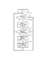
次に、図5を用いて、本発明にかかる電源管理システム15の動作について説明する。
Next, the operation of the
電源管理システム15は、電源制御を行う電化製品20が接続されているか否かを確認する(ステップS21)。
接続されていなければ(ステップS21でNo)、電化製品20が接続されるまで、接続判定を繰り返し行う。
The
If not connected (No in step S21), the connection determination is repeated until the
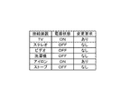
電源管理システム15は、電源制御を行う電化製品20が接続されている場合には(ステップS21でYes)、接続機器の電源のON/OFF情報を取得し、電源状態テーブルを作成する(ステップS22)。図6は、電源状態テーブルの一例である。電源状態テーブルには、接続装置名と、電源状態が記載されている。なお、電源管理システム15は、前回の電源状態テーブルの情報を保持している場合には、電源状態テーブルの更新を行う。
When the
電源管理システム15は、無線LAN機器31から電化製品20への接続情報の取得要求(接続情報取得要求)があるか否かを確認する(ステップS23)。無線LAN機器31から接続情報取得要求がある場合には(ステップS23でYes)、電源管理システム15は、電源状態テーブルを無線LAN機器31に伝達し(ステップS24)、ステップS25に進む。無線LAN機器31から接続情報取得要求がない場合には(ステップS23でNo)、ステップS25に進む。
The
電源管理システム15は、無線LAN機器31から、電化製品20の電源制御要求があるか否かを確認する(ステップS25)。具体的には、電源管理システム15は、無線LAN機器31から伝達された電源状態変更テーブルに基づいて、電源制御要求があるか否かを確認する。
電源管理システム15は、無線LAN機器31から、電源制御要求がある場合には(ステップS25でYes)、電源状態変更テーブルに基づいて、接続されている電化製品20の電源のON/OFF制御を行う(ステップS26)。電源状態変更テーブルは、電化製品20の電源制御が行われた後に情報を更新し、最新の電源状態および変更要求を記録する。その後、ステップS21に戻り、電源制御する電化製品20があるか否かの確認を行う。
無線LAN機器31から、電源制御要求がない場合には(ステップS25でNo)、ステップS21に戻り、電源制御する電化製品20があるか否かの確認を行う。
The
When there is a power control request from the wireless LAN device 31 (Yes in step S25), the
If there is no power control request from the wireless LAN device 31 (No in step S25), the process returns to step S21 to check whether or not there is an
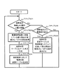
次に、図7を用いて、本発明にかかる無線LAN機器31の動作について説明する。
Next, the operation of the
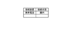
無線LAN機器31は、携帯端末60が無線LANの圏内から圏外へ移動したか否かを監視する(ステップS31)。図8は、無線LAN機器31に登録されている接続装置と、その接続状態を示すテーブルの例である。
The
無線LAN機器31は、携帯端末60が無線LANの圏内から圏外へ移動したことを認識した場合(ステップS31でYes)、電源管理システム15が取得した電化製品20の電源のON/OFF状態の情報を取得する(ステップS32)。電源管理システム15からの電源のON/OFF状態の取得は、図5に示した電源状態テーブルを受信することで行う。
When the
無線LAN機器31は、メール本文に電源状態テーブルを記載して電源制御のメールを作成し(ステップS33)、携帯端末60に送信する(ステップS34)。
The
これにより電源管理テーブルの情報は、無線LAN機器31に接続された公衆網40を介して、携帯端末60に伝達される。無線LAN機器31は、携帯端末60に電源制御のメールを送信後、ステップS31に戻り、携帯端末60が無線LANの圏内から圏外へ移動したか否かを監視する。
As a result, the information in the power management table is transmitted to the
無線LAN機器31は、携帯端末60が無線LANの圏内から圏外へ移動したことを認識ない場合には(ステップS31でNo)、携帯端末60から公衆網40を介して、メールで電源制御の要求があるか否かを確認する(ステップS35)。
If the
携帯端末60からの電源操作の要求がある場合には(ステップS35でYes)、無線LAN機器31は、図3に示した電源状態変更テーブルを電源管理システム15に伝達し、電源管理システム15に接続された電化製品20の、電源のON/OFF状態の制御を要求する(ステップS36)。
その後、ステップS31に戻り、無線LAN機器31は、携帯端末60が無線LANの圏内から圏外へ移動したか否かを監視する。
If there is a request for power operation from the portable terminal 60 (Yes in step S35), the
Thereafter, the process returns to step S31, and the
携帯端末60からの電源操作の要求がない場合には(ステップS35でNo)、ステップS31に戻り、無線LAN機器31は、携帯端末60が無線LANの圏内から圏外へ移動したか否かを監視する。
If there is no request for power operation from the mobile terminal 60 (No in step S35), the process returns to step S31, and the
これにより、電源管理システム15は、無線LAN機器31の圏外認識に基づいて使用者の外出認識を行い、使用者に電化製品20の電源状態を通知することができる。また、使用者は外出先から、携帯端末60を操作することで、電化製品20の電源状態を制御することができる。
本実施の形態によれば、電源管理システム11に鍵施錠を認識させる必要が無いため、鍵施錠を認識させるように施設を改造する必要が無く、また、鍵施錠ができない施設であっても使用が可能である。さらに電源管理システム11は、使用者が、鍵施錠を必要とする施設の鍵施錠を忘れた場合であっても、電化製品20の電源状態を通知することができる。
As a result, the
According to the present embodiment, since it is not necessary to make the
なお、本発明は上記実施の形態に限られたものではなく、趣旨を逸脱しない範囲で適宜変更することが可能である。
実施の形態1において、監視部11は、検出部12により携帯端末60が通信圏外であると判定することや、携帯端末60からの指示の受信を契機として、電化製品20の電源状態を取得するものとしたが、一定時間ごとに電化製品20の電源状態を取得することとしても良い。
実施の形態2では、電源状態テーブルや電源状態変更テーブルを用いて、複数の電化製品20の電源状態をまとめて扱うものとして説明したが、個別の電化製品ごとに、電源情報や電源状態の変更情報を扱うこととしても良い。
実施の形態2では、圏外/圏内認識を行う装置として無線LAN機器31を用いることものとして説明したが、フェムトセルのような小さな通話エリアの小型基地局や家庭内用の構内基地局などを用いることも可能である。
携帯端末60と、電源管理システム10や無線LAN機器30との情報の送受信に、メールを用いるものとして説明したが、メールを用いない通信によって情報の送受信を行っても良い。
Note that the present invention is not limited to the above-described embodiment, and can be changed as appropriate without departing from the spirit of the present invention.
In the first embodiment, the
In the second embodiment, the power supply state table and the power supply state change table are used to collectively handle the power supply states of the plurality of
In the second embodiment, the
Although it has been described that mail is used for transmission / reception of information between the
上述の例において、システムのハードディスク、メモリ等の記憶手段等にインストールされた各種のプログラムは、様々なタイプの非一時的なコンピュータ可読媒体(non-transitory computer readable medium)を用いて格納され、コンピュータに供給することができる。非一時的なコンピュータ可読媒体は、様々なタイプの実体のある記録媒体(tangible storage medium)を含む。非一時的なコンピュータ可読媒体の例は、磁気記録媒体(例えばフレキシブルディスク、磁気テープ、ハードディスクドライブ)、光磁気記録媒体(例えば光磁気ディスク)、CD−ROM(Read Only Memory)、CD−R、CD−R/W、半導体メモリ(例えば、マスクROM、PROM(Programmable ROM)、EPROM(Erasable PROM)、フラッシュROM、RAM(random access memory))を含む。また、プログラムは、様々なタイプの一時的なコンピュータ可読媒体(transitory computer readable medium)によってコンピュータに供給されてもよい。一時的なコンピュータ可読媒体の例は、電気信号、光信号、及び電磁波を含む。一時的なコンピュータ可読媒体は、電線及び光ファイバ等の有線通信路、又は無線通信路を介して、プログラムをコンピュータに供給できる。 In the above example, the various programs installed in the storage means such as the hard disk and memory of the system are stored using various types of non-transitory computer readable media, and the computer. Can be supplied to. Non-transitory computer readable media include various types of tangible storage media. Examples of non-transitory computer-readable media include magnetic recording media (for example, flexible disks, magnetic tapes, hard disk drives), magneto-optical recording media (for example, magneto-optical disks), CD-ROMs (Read Only Memory), CD-Rs, CD-R / W and semiconductor memory (for example, mask ROM, PROM (Programmable ROM), EPROM (Erasable PROM), flash ROM, RAM (random access memory)) are included. The program may also be supplied to the computer by various types of transitory computer readable media. Examples of transitory computer readable media include electrical signals, optical signals, and electromagnetic waves. The temporary computer-readable medium can supply the program to the computer via a wired communication path such as an electric wire and an optical fiber, or a wireless communication path.
1 通信システム
2 通信システム
10 電源管理システム
11 監視部
12 検出部
13 通信部
20 電化製品
30 無線LAN機器
31 無線LAN機器
40 公衆網
50 基地局
60 携帯端末
DESCRIPTION OF
Claims (8)
携帯端末が無線LANの通信圏外であることを検出する検出部と、
前記携帯端末との通信を行う通信部と、を備え、
前記検出部により前記携帯端末が前記無線LANの通信圏外であると検出されたことを契機として、前記通信部は、前記監視部で取得された前記電化製品の電源状態を前記携帯端末に通知する、電源管理システム。 A monitoring unit for obtaining the power status of the electrical appliance;
A detection unit for detecting that the mobile terminal is out of a wireless LAN communication range;
A communication unit that communicates with the mobile terminal,
When the detection unit detects that the mobile terminal is out of the wireless LAN communication range, the communication unit notifies the mobile terminal of the power state of the appliance acquired by the monitoring unit. , Power management system.
請求項1に記載の電源管理システム。 The detection unit detects that the mobile terminal is out of a wireless LAN communication range based on information on a communication state of a wireless LAN device performing communication with the mobile terminal and the wireless LAN.
The power management system according to claim 1.
請求項1又は請求項2に記載の電源管理システム。 The detection unit detects that the mobile terminal is out of a communication range of a wireless LAN based on information transmitted from a base station connected to the mobile terminal for communication via a public network.
The power management system according to claim 1 or 2.
請求項3に記載の電源管理システム。 The detection unit detects that the mobile terminal is out of a communication range of a wireless LAN based on position information transmitted from the base station.
The power management system according to claim 3.
請求項1〜請求項4のいずれか一項に記載の電源管理システム。 The detection unit receives information transmitted from the mobile terminal via the public network when the mobile terminal is out of a wireless LAN communication range, thereby confirming that the mobile terminal is out of a wireless LAN communication range. To detect,
The power management system as described in any one of Claims 1-4.
携帯端末が無線LANの通信圏外であることを検出し、
前記携帯端末が前記無線LANの通信圏外であると検出されたことを契機として、取得された前記電化製品の電源状態を前記携帯端末に送信する、
電源管理システムの制御方法。 Get the power status of the appliance
Detect that the mobile terminal is outside the wireless LAN communication range,
Triggered when the mobile terminal is detected to be out of the communication range of the wireless LAN, the acquired power state of the appliance is transmitted to the mobile terminal.
Control method of power management system.
Priority Applications (1)
| Application Number | Priority Date | Filing Date | Title |
|---|---|---|---|
| JP2011056761A JP2012196016A (en) | 2011-03-15 | 2011-03-15 | Power supply management system, portable terminal, control method for power supply management system, and program thereof |
Applications Claiming Priority (1)
| Application Number | Priority Date | Filing Date | Title |
|---|---|---|---|
| JP2011056761A JP2012196016A (en) | 2011-03-15 | 2011-03-15 | Power supply management system, portable terminal, control method for power supply management system, and program thereof |
Publications (1)
| Publication Number | Publication Date |
|---|---|
| JP2012196016A true JP2012196016A (en) | 2012-10-11 |
Family
ID=47087443
Family Applications (1)
| Application Number | Title | Priority Date | Filing Date |
|---|---|---|---|
| JP2011056761A Withdrawn JP2012196016A (en) | 2011-03-15 | 2011-03-15 | Power supply management system, portable terminal, control method for power supply management system, and program thereof |
Country Status (1)
| Country | Link |
|---|---|
| JP (1) | JP2012196016A (en) |
Cited By (11)
| Publication number | Priority date | Publication date | Assignee | Title |
|---|---|---|---|---|
| WO2015001808A1 (en) * | 2013-07-05 | 2015-01-08 | パナソニック インテレクチュアル プロパティ コーポレーション オブ アメリカ | Information notification method |
| WO2015001809A1 (en) * | 2013-07-05 | 2015-01-08 | パナソニック インテレクチュアル プロパティ コーポレーション オブ アメリカ | Information notification method |
| WO2015033540A1 (en) * | 2013-09-04 | 2015-03-12 | パナソニック インテレクチュアル プロパティ コーポレーション オブ アメリカ | Information notification method |
| JP5829358B2 (en) * | 2013-09-12 | 2015-12-09 | パナソニック インテレクチュアル プロパティ コーポレーション オブアメリカPanasonic Intellectual Property Corporation of America | Information notification method |
| WO2016006087A1 (en) * | 2014-07-10 | 2016-01-14 | 株式会社 東芝 | Control device, method, and program |
| JP2016025601A (en) * | 2014-07-23 | 2016-02-08 | 富士通株式会社 | Remote operation controller, remote operation controlling method, and remote operation controlling system |
| JP5866543B1 (en) * | 2014-11-21 | 2016-02-17 | パナソニックIpマネジメント株式会社 | Home monitoring system and monitoring method in home monitoring system |
| US20170025861A1 (en) * | 2015-07-23 | 2017-01-26 | General Electric Company | Detecting the presence or absence of a user |
| JP2017513440A (en) * | 2014-01-22 | 2017-05-25 | 富士通株式会社 | Residential and small business demand response |
| JP2018011359A (en) * | 2017-10-12 | 2018-01-18 | パナソニックIpマネジメント株式会社 | Load control system |
| JP2020205697A (en) * | 2019-06-18 | 2020-12-24 | Necプラットフォームズ株式会社 | Wireless communication device, communication system, operation method of wireless communication device and program |
-
2011
- 2011-03-15 JP JP2011056761A patent/JP2012196016A/en not_active Withdrawn
Cited By (15)
| Publication number | Priority date | Publication date | Assignee | Title |
|---|---|---|---|---|
| WO2015001808A1 (en) * | 2013-07-05 | 2015-01-08 | パナソニック インテレクチュアル プロパティ コーポレーション オブ アメリカ | Information notification method |
| WO2015001809A1 (en) * | 2013-07-05 | 2015-01-08 | パナソニック インテレクチュアル プロパティ コーポレーション オブ アメリカ | Information notification method |
| WO2015033540A1 (en) * | 2013-09-04 | 2015-03-12 | パナソニック インテレクチュアル プロパティ コーポレーション オブ アメリカ | Information notification method |
| JP5829358B2 (en) * | 2013-09-12 | 2015-12-09 | パナソニック インテレクチュアル プロパティ コーポレーション オブアメリカPanasonic Intellectual Property Corporation of America | Information notification method |
| US9762407B2 (en) | 2013-09-12 | 2017-09-12 | Panasonic Intellectual Property Corporation Of America | Information notification method |
| JP2017513440A (en) * | 2014-01-22 | 2017-05-25 | 富士通株式会社 | Residential and small business demand response |
| US9953285B2 (en) | 2014-01-22 | 2018-04-24 | Fujitsu Limited | Residential and small and medium business demand response |
| WO2016006087A1 (en) * | 2014-07-10 | 2016-01-14 | 株式会社 東芝 | Control device, method, and program |
| JP2016025601A (en) * | 2014-07-23 | 2016-02-08 | 富士通株式会社 | Remote operation controller, remote operation controlling method, and remote operation controlling system |
| JP5866543B1 (en) * | 2014-11-21 | 2016-02-17 | パナソニックIpマネジメント株式会社 | Home monitoring system and monitoring method in home monitoring system |
| US9401814B2 (en) | 2014-11-21 | 2016-07-26 | Panasonic Intellectual Property Management Co., Ltd. | House monitoring system |
| US20170025861A1 (en) * | 2015-07-23 | 2017-01-26 | General Electric Company | Detecting the presence or absence of a user |
| JP2018011359A (en) * | 2017-10-12 | 2018-01-18 | パナソニックIpマネジメント株式会社 | Load control system |
| JP2020205697A (en) * | 2019-06-18 | 2020-12-24 | Necプラットフォームズ株式会社 | Wireless communication device, communication system, operation method of wireless communication device and program |
| JP7036441B2 (en) | 2019-06-18 | 2022-03-15 | Necプラットフォームズ株式会社 | Wireless communication device, communication system, operation method and program of wireless communication device |
Similar Documents
| Publication | Publication Date | Title |
|---|---|---|
| JP2012196016A (en) | Power supply management system, portable terminal, control method for power supply management system, and program thereof | |
| US10943470B2 (en) | Method and apparatus for controlling a home device remotely in a home network system | |
| US10314088B2 (en) | Associating devices and users with a local area network using network identifiers | |
| US10231268B2 (en) | Associating devices and users with a local area network using network identifiers | |
| US10257159B2 (en) | Methods, systems, and apparatuses for providing a single network address translation connection for multiple devices | |
| US20180375919A1 (en) | Method and apparatus for remotely controlling home device in home network system | |
| US20180376317A1 (en) | Proxy device for reducing number of connections to gateway | |
| US20120331156A1 (en) | Wireless control system, methods and apparatus | |
| JP6239465B2 (en) | Information equipment and control equipment | |
| JP2007274208A (en) | Power supply control method, and controller and terminal device utilizing the same | |
| JP2016005228A (en) | Terminal device and radio device | |
| JP2007052706A (en) | Remote supervisory control system, gateway unit, and center server | |
| US20140173068A1 (en) | Management Apparatus and Address Management Method | |
| JP2012129916A (en) | Communication device | |
| KR101573785B1 (en) | HOME NETWORK SYSTEM USING Z-Wave NETWORK AND HOME AUTOMATION APPLIANCE CONNECTION METHOD USING THE SAME | |
| JP6270542B2 (en) | Authentication system | |
| KR20160100043A (en) | Consent Device for Proving Heterogeneous Wireless Local Area Communication | |
| JP6072746B2 (en) | Access point device, communication system, wireless LAN communication connection release method and program | |
| WO2018137353A1 (en) | Method and apparatus for controlling state of controllable device | |
| JP2017022556A (en) | Communication device and communication method | |
| WO2012077657A1 (en) | Monitoring control device, monitoring control system | |
| JP2011004130A (en) | Network communication system and method for setting network communication system | |
| KR20170016418A (en) | Consent Device based on Bluetooth | |
| JP2016099805A (en) | Gateway device, monitoring system, monitoring method and monitoring program | |
| JP2017076856A (en) | Home gateway, consumer electronics coordination system, method and program therefor |
Legal Events
| Date | Code | Title | Description |
|---|---|---|---|
| A300 | Withdrawal of application because of no request for examination |
Free format text: JAPANESE INTERMEDIATE CODE: A300 Effective date: 20140603 |