JP2012194035A - Apparatus and method for diagnosing fault of speed reducer - Google Patents
Apparatus and method for diagnosing fault of speed reducer Download PDFInfo
- Publication number
- JP2012194035A JP2012194035A JP2011057849A JP2011057849A JP2012194035A JP 2012194035 A JP2012194035 A JP 2012194035A JP 2011057849 A JP2011057849 A JP 2011057849A JP 2011057849 A JP2011057849 A JP 2011057849A JP 2012194035 A JP2012194035 A JP 2012194035A
- Authority
- JP
- Japan
- Prior art keywords
- motor
- transmission efficiency
- output shaft
- torque
- speed reducer
- Prior art date
- Legal status (The legal status is an assumption and is not a legal conclusion. Google has not performed a legal analysis and makes no representation as to the accuracy of the status listed.)
- Granted
Links
- 239000003638 chemical reducing agent Substances 0.000 title claims abstract description 60
- 238000000034 method Methods 0.000 title claims description 14
- 230000005540 biological transmission Effects 0.000 claims abstract description 55
- 238000004364 calculation method Methods 0.000 claims abstract description 47
- 230000005856 abnormality Effects 0.000 claims description 73
- 238000003745 diagnosis Methods 0.000 claims description 34
- 238000012545 processing Methods 0.000 claims description 22
- 238000013500 data storage Methods 0.000 description 8
- 230000007246 mechanism Effects 0.000 description 6
- 230000000694 effects Effects 0.000 description 4
- 230000002159 abnormal effect Effects 0.000 description 3
- 238000007796 conventional method Methods 0.000 description 3
- 238000010586 diagram Methods 0.000 description 3
- 239000004519 grease Substances 0.000 description 3
- 238000001228 spectrum Methods 0.000 description 3
- 101000911772 Homo sapiens Hsc70-interacting protein Proteins 0.000 description 2
- 230000033001 locomotion Effects 0.000 description 2
- 238000012360 testing method Methods 0.000 description 2
- 101001139126 Homo sapiens Krueppel-like factor 6 Proteins 0.000 description 1
- 101000661807 Homo sapiens Suppressor of tumorigenicity 14 protein Proteins 0.000 description 1
- 238000001514 detection method Methods 0.000 description 1
- 238000005259 measurement Methods 0.000 description 1
- 238000012986 modification Methods 0.000 description 1
- 230000004048 modification Effects 0.000 description 1
- 230000010349 pulsation Effects 0.000 description 1
- 230000003252 repetitive effect Effects 0.000 description 1
- 230000003595 spectral effect Effects 0.000 description 1
Images


Abstract
Description
本発明は、減速機異常診断装置および減速機異常診断方法に関する。 The present invention relates to a speed reducer abnormality diagnosis device and a speed reducer abnormality diagnosis method.
例えばロボットの関節部分には減速機が設けられており、駆動速度およびトルクの調整が行われる。
ロボットを長時間にわたって稼働していると、減速機の歯が摩耗したり、グリスが不足してきたり、極端にいえば、歯が欠けてしまうこともあり得る。このような異常が発生すると、予期しないトルクが発生してしまう。そこで、減速機の異常を診断して検出する各種の方法が提案されている。
For example, a speed reducer is provided at the joint portion of the robot, and the drive speed and torque are adjusted.
If the robot is operated for a long time, the teeth of the reducer may be worn out, the grease may be insufficient, or in extreme cases, the teeth may be lost. When such an abnormality occurs, an unexpected torque is generated. Therefore, various methods for diagnosing and detecting an abnormality of the reduction gear have been proposed.
減速機等の回転体の異常を診断する方法としては、一般に次のようなものが知られている(例えば特許文献1)。すなわち、診断対象にセンサを取り付け、センサの観測値を周波数分解する。上記で得られたスペクトルパターンを正常なパターンと対比する。例えば、周波数成分の平均値やピーク値などを比較する。比較結果に基づき、回転体の異常が検出する。 As a method for diagnosing abnormality of a rotating body such as a speed reducer, the following is generally known (for example, Patent Document 1). That is, a sensor is attached to a diagnosis target, and the observed value of the sensor is frequency-resolved. The spectral pattern obtained above is compared with a normal pattern. For example, the average value and peak value of frequency components are compared. Based on the comparison result, an abnormality of the rotating body is detected.
従来の手法は、センサによって得られた時系列データを周波数分解して、このスペクトルを正常時と比較することで異常診断するものである。確かに、上記手法は、工場内で定型動作を繰り返し続ける産業用ロボットに対しては適用できる。
しかしながら、近年開発が進んでいるサービスロボットでは、作業内容や環境によってその動作が時々刻々と変化する。すると、正常動作を示すスペクトルといった概念自体が存在しなくなる。したがって、定型動作がないサービスロボットに対しては上記文献に挙げられた手法はいずれも適用できない。
In the conventional technique, time series data obtained by a sensor is frequency-resolved, and an abnormality is diagnosed by comparing this spectrum with a normal time. Certainly, the above method can be applied to industrial robots that continue to perform routine operations in a factory.
However, in a service robot that has been developed in recent years, its operation changes from moment to moment depending on the work content and environment. Then, the concept itself such as a spectrum indicating normal operation does not exist. Therefore, none of the methods listed in the above document can be applied to a service robot that does not have a fixed movement.
サービスロボットが人間と近接した環境で動作を行う場合、減速機等の駆動系の故障はできる限り速やかに検出することが必要である。従来技術とは異なる新規な発想による減速機異常診断方法が求められている。 When the service robot operates in an environment close to humans, it is necessary to detect a failure of a drive system such as a speed reducer as quickly as possible. There is a need for a speed reducer abnormality diagnosis method based on a new idea different from the prior art.
本発明の目的は、繰り返しの定型動作を行わず、動作が時々刻々と変化する場合であっても、動作内容に関係なく減速機の異常診断を行うことができる減速機異常診断装置および減速機異常診断方法を提供することにある。 An object of the present invention is to provide a speed reducer abnormality diagnosis device and a speed reducer that are capable of diagnosing a speed reducer abnormality regardless of the operation content even when the operation changes every moment without performing a repetitive routine operation. It is to provide an abnormality diagnosis method.
本発明の減速機異常診断装置は、
モータの回転速度を減じて出力する減速機の異常を診断する減速機異常診断装置であって、
前記モータまたは前記減速機の出力軸の回転角度範囲内で複数設定された観測点を記憶した観測点設定記憶部と、
前記出力軸の回転角が前記観測点のいずれかに一致するごとに、その観測点におけるモータトルクと減速後トルクとの比をトルク伝達効率として算出するトルク伝達効率算出部と、
前記算出されたトルク伝達効率と正常時データ値との統計的距離を算出する統計距離算出部と、
前記算出された統計的距離を所定閾値と対比して前記統計的距離が前記所定閾値を超えた場合に異常判定を行う異常判定部と、を備える
ことを特徴とする。
The speed reducer abnormality diagnosis device of the present invention is
A reduction gear abnormality diagnosis device for diagnosing abnormality of a reduction gear that outputs by reducing the rotation speed of a motor,
An observation point setting storage unit storing a plurality of observation points set within a rotation angle range of the output shaft of the motor or the speed reducer;
A torque transmission efficiency calculating unit that calculates a ratio of the motor torque and the post-deceleration torque at the observation point as torque transmission efficiency each time the rotation angle of the output shaft matches any of the observation points;
A statistical distance calculator for calculating a statistical distance between the calculated torque transmission efficiency and a normal data value;
An abnormality determining unit that compares the calculated statistical distance with a predetermined threshold value and performs an abnormality determination when the statistical distance exceeds the predetermined threshold value.
本発明では、
前記統計距離算出部は、マハラノビス距離を統計的距離として算出する
ことが好ましい。
In the present invention,
Preferably, the statistical distance calculation unit calculates the Mahalanobis distance as a statistical distance.
本発明では、
前記モータの後段に設けられこのモータの出力軸の回転を検出するロータリーエンコーダと、
前記ロータリーエンコーダからのセンサ信号に基づいて前記出力軸の回転角を算出するモータ角度算出部と、
前記算出された回転角を前記観測点に対比して、回転角が前記観測点に一致したときにタイミング信号を出力するタイミング指示部と、を備え、
前記トルク伝達効率算出部および統計距離算出部は、前記タイミング信号を受信したときに処理動作を開始する
ことが好ましい。
In the present invention,
A rotary encoder provided at a subsequent stage of the motor for detecting the rotation of the output shaft of the motor;
A motor angle calculation unit for calculating a rotation angle of the output shaft based on a sensor signal from the rotary encoder;
A timing indicator that outputs the timing signal when the rotation angle coincides with the observation point by comparing the calculated rotation angle with the observation point;
Preferably, the torque transmission efficiency calculation unit and the statistical distance calculation unit start a processing operation when receiving the timing signal.
本発明では、
前記出力軸の回転速度を算出する回転速度算出部を備え、
前記正常値データは、前記出力軸の回転速度に応じて変化するように用意されており、
前記統計距離算出部は、前記トルク伝達効率算出部にて算出されたトルク伝達効率と、前記算出された回転速度に応じた正常時データと、を用いて統計的距離を算出する
ことが好ましい。
In the present invention,
A rotation speed calculation unit for calculating the rotation speed of the output shaft;
The normal value data is prepared so as to change according to the rotation speed of the output shaft,
It is preferable that the statistical distance calculation unit calculates a statistical distance using the torque transmission efficiency calculated by the torque transmission efficiency calculation unit and normal data corresponding to the calculated rotation speed.
本発明では、
前記観測点は、減速機のすべての歯に対応して設けられている
ことが好ましい。
In the present invention,
The observation point is preferably provided corresponding to all teeth of the speed reducer.
本発明の減速機異常診断方法は、
モータの回転速度を減じて出力する減速機の異常を診断する減速機異常診断方法であって、
前記モータまたは前記減速機の出力軸の回転角度範囲内で観測点を複数設定し、
前記出力軸の回転角が前記観測点のいずれかに一致するごとに、その観測点におけるモータトルクと減速後トルクとの比をトルク伝達効率として算出し、
前記算出されたトルク伝達効率と正常時データ値との統計的距離を算出し、
前記算出された統計的距離を所定閾値と対比して前記統計的距離が前記所定閾値を超えた場合に異常判定を行う
ことを特徴とする。
The speed reducer abnormality diagnosis method of the present invention includes:
A reduction gear abnormality diagnosis method for diagnosing an abnormality of a reduction gear that outputs by reducing the rotation speed of a motor,
Set a plurality of observation points within the rotation angle range of the output shaft of the motor or the speed reducer,
Each time the rotation angle of the output shaft matches any of the observation points, the ratio of the motor torque and the post-deceleration torque at the observation point is calculated as the torque transmission efficiency,
Calculating a statistical distance between the calculated torque transmission efficiency and a normal data value;
The calculated statistical distance is compared with a predetermined threshold value, and an abnormality is determined when the statistical distance exceeds the predetermined threshold value.
本発明の実施の形態を図示するとともに図中の各要素に付した符号を参照して説明する。
(第1実施形態)
本発明の減速機異常診断装置に係る第1実施形態について説明する。
図1は、第1実施形態に係る減速機異常診断装置を示す図である。
まず、測定対象としての駆動機構部100について説明する。
駆動機構部100は、例えば、ロボットの関節部に適用される。
駆動機構部100は、モータ110と、減速機130と、リンク140と、を備える。
モータ110は、モータ駆動回路120からの電流指令によって回転駆動する。モータ110の出力軸を第1出力軸111と称する。
Embodiments of the present invention will be illustrated and described with reference to reference numerals attached to respective elements in the drawings.
(First embodiment)
A first embodiment according to the speed reducer abnormality diagnosis device of the present invention will be described.
FIG. 1 is a diagram illustrating a speed reducer abnormality diagnosis device according to the first embodiment.
First, the
The
The
The
減速機130は、前記第1出力軸111に直結されている。また、減速機130の出力軸は、リンク140に取り付けられている。
減速機130の出力軸を第2出力軸131と称する。
減速機130は、第1出力軸111の回転を減速させ、減速した回転を第2出力軸131から取り出すようになっている。減速機130としては、各種の歯車機構を用いた既知のものが適用可能である。
第2出力軸131の回転に連動してリンク140が回転し、指令に従った速度およびトルクでロボットの関節駆動が実現する。
The
The output shaft of the
The speed reducer 130 decelerates the rotation of the first output shaft 111 and takes out the decelerated rotation from the
The
次に、減速機異常診断装置200について説明する。
減速機異常診断装置200は、ロータリーエンコーダ210と、トルクセンサ220と、演算制御部230と、を備える。
ロータリーエンコーダ210は、第1出力軸111の回転角度を検出するセンサである。ロータリーエンコーダ210としては、インクリメント式でもよいが、アブソリュートエンコーダであることが好ましい。第1出力軸111の回転にともなってエンコーダ210からのセンサ信号が時々刻々変化するところ、エンコーダ210からのセンサ信号は演算制御部230に入力される。
Next, the speed reducer
The reducer
The
トルクセンサ220は、減速機130の後段に設けられ、第2出力軸131の回転トルクを検出する。第2出力軸131の回転に伴ってトルクセンサ220からのセンサ信号が時々刻々変化するところ、トルクセンサ220からのセンサ信号は演算制御部230に入力される。トルクセンサ220としては、特に限定されるものではなく、既知のトルクセンサ(トルクメータ)を使用できる。
The
演算制御部230は、タイミング制御部240と、観測データ処理部250と、統計処理部260と、を備える。
The
タイミング制御部240は、異常診断の実行タイミングを制御する。
タイミング制御部240は、第1出力軸111の回転角度が所定角度に達したときに、タイミング信号を出力する。このタイミング信号によって観測データ処理部250は観測データの演算処理を実行し、統計処理部260は統計的演算処理を実行する。すなわち、第1出力軸111の回転角度が所定角度に達したときに減速機130の異常診断が行われることになる。
The
The
タイミング制御部240は、観測点設定記憶部241と、モータ角度算出部242と、タイミング指示部243と、を備える。
The
観測点設定記憶部241には、予め、複数の角度値が観測点として設定登録されている。観測点は、例えば、図2に示すように、360度を45度ずつ8分割して設定される。
この場合、各観測点は次のようになる。
P0=0°
P1=45°
P2=90°
P3=135°
P4=180°
P5=225°
P6=270°
P7=315°
In the observation point setting
In this case, each observation point is as follows.
P0 = 0 °
P1 = 45 °
P2 = 90 °
P3 = 135 °
P4 = 180 °
P5 = 225 °
P6 = 270 °
P7 = 315 °
観測点設定記憶部241には、上記8点(P0からP7)の角度値が観測点として設定登録されている。
In the observation point setting
モータ角度算出部242は、エンコーダ210からのセンサ信号に基づいて第1出力軸111の回転角を算出する。算出された回転角度値はタイミング指示部243に出力される。
The motor
タイミング指示部243は、前記算出された回転角度値と前記観測点とを対比して、回転角度値が観測点のいずれかを跨ぐたびに、タイミング信号を出力する。
The
観測データ処理部250は、タイミング信号を受けると、モータトルクと減速機130の出力トルクとからトルク伝達効率r(トルク比)を算出する。
観測データ処理部250は、モータトルク算出部251と、観測トルク算出部252と、伝達効率算出部253と、を備える。
モータトルク算出部251は、モータ110への電流指令値からモータ110の出力トルクを算出する。
以後、モータ110の出力トルクをモータトルクτと称する。
観測トルク算出部252は、トルクセンサ220からのセンサ信号に基づいて減速機の出力トルクを算出する。
以後、減速機の出力トルクを観測トルクTと称する。
When receiving the timing signal, the observation
The observation
The motor
Hereinafter, the output torque of the
The observed
Hereinafter, the output torque of the speed reducer is referred to as observed torque T.
伝達効率算出部253は、モータトルクτと観測トルクTとからトルク伝達効率rを算出する。
The transmission

ここで、kは減速機130による減速比を表す。
仮に減速機130でトルク損失が発生しないとすると(効率100%)、モータトルクと減速比との積(k×τ)がそのまま第2出力軸131で得られるトルクになる。したがって、上記riは、トルクに関する減速機130の伝達効率を表すものである。
Here, k represents a reduction ratio by the
Assuming that no torque loss occurs in the reduction gear 130 (
第1出力軸111の回転角が観測点Piを跨ぐたびにトルク伝達効率riが算出される。算出されたトルク伝達効率riは、統計処理部260に出力される。
The torque transmission efficiency r i is calculated every time the rotation angle of the first output shaft 111 crosses the observation point P i . The calculated torque transmission efficiency r i is output to the
統計処理部260は、前記算出された伝達効率rを正常値と対比することにより、減速機130の状態を診断する。
統計処理部260は、正常時データ記憶部261と、マハラノビス距離算出部(統計距離算出部)262と、異常判定部263と、を備える。
正常時データ記憶部261は、観測点Piごとに伝達効率rの平均値と偏差平方和σとを記憶している。正常時データは、減速機130が正常動作しているときに試験駆動させて予め取得しておくものである。
The
The
Normal time
例えば、モータ110をm回転させる試験駆動により、観測点Piについての伝達効率riデータが次のように取得されたとする。 For example, it is assumed that the transmission efficiency r i data for the observation point P i is acquired as follows by the test drive that rotates the motor 110 m times.
観測点Piについて取得された伝達効率データ
:r1i、r2i、r3i、r4i、・・・rji、・・・・rmi
Observation point P i is the transmission efficiency data obtained for: r 1i, r 2i, r 3i, r 4i, ··· r ji, ···· r mi
すると、平均値は次のようになる。 Then, the average value is as follows.
また、偏差平方和は次のようになる。 The deviation sum of squares is as follows.
伝達効率の平均値および偏差平方和を観測点Pごとにまとめると、正常時データは例えば図3のようになる。 When the average value of transmission efficiency and the sum of squared deviations are summarized for each observation point P, normal data is as shown in FIG. 3, for example.
マハラノビス距離算出部262は、算出された伝達効率rと正常時データとから、マハラノビス距離を算出する。
第1出力軸111の回転角が観測点Piを跨ぐと、その旨がタイミング指令として観測データ処理部250とマハラノビス距離算出部262とに指令される。すると、前述のように、観測データ処理部250では観測点Piを跨ぐときのトルク伝達効率riが算出される。この算出された伝達効率riはマハラノビス距離算出部262に出力される。
一方、マハラノビス距離算出部262は、タイミング指令に応じて、観測点Piに対応する正常時データを正常時データ記憶部261から取得する。
(このタイミング指令には、処理対象となる観測点を特定する情報が含まれているとする。)
マハラノビス距離Di 2は次のように算出される。
The Mahalanobis
When the rotation angle of the first output shaft 111 crosses the observation point P i, the fact is commanded to the observation
On the other hand, the Mahalanobis
(It is assumed that this timing command includes information for specifying an observation point to be processed.)
The Mahalanobis distance D i 2 is calculated as follows.
このように算出されたマハラノビス距離Di 2は、異常判定部263に出力される。
The Mahalanobis distance D i 2 calculated in this way is output to the
異常判定部263は、算出されたマハラノビス距離Di 2を所定の判定閾値Dth 2と対比する。判定閾値Dth 2は、例えば、3から4程度に設定される。
マハラノビス距離Di 2が判定閾値以下である場合(Di 2≦Dth 2)、減速機130の動作は正常であると判定する。
一方、マハラノビス距離Di 2が判定閾値Dth 2を超える場合(Di 2>Dth 2)、トルク伝達効率が(統計的にみて)正常の範囲から大幅に外れていることになる。
観測点Piにおいてトルク伝達効率が異常であるということから次のことが考えられる。
すなわち、減速機130には一般に歯車機構が含まれるところ、観測点Piに対応する歯が摩耗したり、グリスが不足してきたり、極端にいえば、歯が欠けてしまったりして、力の伝達に異常が生じているということである。このように、マハラノビス距離Di 2が判定閾値Dth 2を超えてしまう異常値が一つの観測点で検出された場合には、減速機130に異常があるとして異常判定部263は異常判定信号を出力する。
The
When the Mahalanobis distance D i 2 is less than or equal to the determination threshold (D i 2 ≦ D th 2 ), it is determined that the operation of the
On the other hand, when the Mahalanobis distance D i 2 exceeds the determination threshold D th 2 (D i 2 > D th 2 ), the torque transmission efficiency is significantly out of the normal range (statistically).
The following can be considered from the fact that the torque transmission efficiency is abnormal at the observation point P i .
In other words, the
異常判定信号を受けた後段の装置(不図示)は、異常をユーザーに知らせるように所定の表示手段で表示してもよく、あるいは、ロボットの駆動を停止させるようにしてもよい。 A subsequent device (not shown) that has received the abnormality determination signal may display the abnormality on a predetermined display means so as to notify the user of the abnormality, or may stop the driving of the robot.
このような減速機異常診断装置200によれば、次の効果を奏することができる。
(1)従来は、センサによって得られた時系列データを周波数分解して、このスペクトルを正常時と比較することで異常診断をしていた。この手法は、工場内で定型動作を繰り返し続ける産業用ロボットに対しては適用できるが、人間と近接した環境で作業するサービスロボットは作業内容や環境によってその動作が時々刻々と変化するので、従来の手法は適用できなかった。
この点、本実施形態では、観測点ごとに求めたトルク伝達効率rに基づいて減速機の状態を診断するので、時系列データの周波数成分を調べるようなことは必要ない。すなわち、繰り返しの定型動作を行わず、動作が時々刻々と変化するサービスロボットに対しても動作内容に関係なく減速機の異常診断を行うことができる。
According to such a reduction gear
(1) Conventionally, abnormality diagnosis is performed by frequency-decomposing time-series data obtained by a sensor and comparing this spectrum with normal time. Although this method can be applied to industrial robots that continue to perform routine operations in a factory, service robots that work in an environment close to humans change their operation from moment to moment depending on the work content and environment. This method could not be applied.
In this respect, in the present embodiment, since the state of the reduction gear is diagnosed based on the torque transmission efficiency r obtained for each observation point, it is not necessary to examine the frequency component of the time series data. That is, it is possible to perform a diagnosis of a speed reducer abnormality for a service robot whose operation changes every moment without performing repeated routine operations regardless of the operation content.
(2)また、従来手法では、特定の回転周波数成分を抽出することに主眼を置いていたので、回転動作に相関が弱い異常に関しては検出するのが困難であった。例えば、グリスが劣化して減速機が重くなるような状態は回転周波数の分析からは検知できない。
この点、本実施形態では観測点ごとのトルク伝達効率rに基づいて減速機の状態を診断するので、回転動作自体に関係がない。すなわち、観測点Piのときに噛み合っている歯のいずれかに異常があればトルク伝達効率rが正常な範囲から外れるので、これにより、減速機の異常を検出できる。
(2) Further, in the conventional method, since the focus is on extracting a specific rotational frequency component, it is difficult to detect an abnormality having a weak correlation with the rotational motion. For example, a state where the grease deteriorates and the speed reducer becomes heavy cannot be detected from the analysis of the rotation frequency.
In this respect, in the present embodiment, the state of the speed reducer is diagnosed based on the torque transmission efficiency r for each observation point, so there is no relation to the rotational operation itself. That is, if any of the teeth meshed at the observation point Pi has an abnormality, the torque transmission efficiency r deviates from the normal range, so that the reduction gear abnormality can be detected.
(3)さらに、従来手法では、センサによって得られた時系列データを周波数分解することが必要であるので、減速機等の回転系に異常が発生した後もしばらく何回転かした後、その間の時系列データを調べて初めて異常が確認できることになる。これでは異常を検知するまでにどうしても遅れが生じてしまう。
この点、本実施形態では、観測点を通過するたびに瞬時に異常判定を行うので、リアルタイム判定が可能になる。
(3) Furthermore, in the conventional method, it is necessary to frequency-resolve the time-series data obtained by the sensor. Therefore, after an abnormality occurs in the rotating system such as a speed reducer, after several rotations, Abnormalities can only be confirmed by examining time-series data. This inevitably causes a delay before detecting an abnormality.
In this respect, in the present embodiment, since the abnormality determination is performed instantaneously every time the observation point is passed, real-time determination can be performed.
(4)本実施形態では、観測点ごとに算出したトルク伝達効率rに対して単純に閾値判定するのではなく、正常データからの遠さをマハラノビス距離Di 2として求め、このマハラノビス距離Di 2に対して閾値判定を行っている。
このような統計的処理を介在させているので、信頼性の高い診断が可能になる。
観測データをそのまま閾値判定してしまうとすると、閾値の設定レベルによっては過剰に異常を検出してしまったり、逆に異常を見逃してしまうなどの不都合が生じやすく、閾値レベルの設定調整が難しい。
この点、閾値判定の前に観測データを統計処理しているので、信頼性の高い判断になる。
定型動作しかしない工場ロボットと違って、動作が時々刻々と変化するサービスロボットの場合、動作速度などによって減速機のトルク伝達効率はある程度変化することが見込まれるので、適切な統計処理を介在させることによって信頼性の高い判断が可能になる。
(4) In the present embodiment, instead of simply determining a threshold for the torque transmission efficiency r calculated for each observation point, the distance from normal data is obtained as the Mahalanobis distance D i 2 , and this Mahalanobis distance D i Threshold judgment is performed for 2 .
Since such statistical processing is interposed, highly reliable diagnosis is possible.
If the observation data is directly subjected to threshold determination, depending on the threshold setting level, abnormalities such as excessive detection of abnormalities and conversely overlooking of abnormalities are likely to occur, and adjustment of threshold level settings is difficult.
In this respect, since the observation data is statistically processed before the threshold determination, the determination is highly reliable.
Unlike factory robots, which have only regular operations, service robots whose operation changes from moment to moment are expected to change the torque transmission efficiency of the reducer to some extent depending on the operation speed, etc. Makes it possible to make highly reliable judgments.
(第2実施形態)
次に、本発明の第2実施形態について説明する。
第2実施形態の構成は基本的に第1実施形態と同じであるが、正常時データを観測点ごとに一定値とせず、モータ回転速度に応じて正常時データを変える点に特徴を有する。
(Second embodiment)
Next, a second embodiment of the present invention will be described.
The configuration of the second embodiment is basically the same as that of the first embodiment, but is characterized in that the normal data is not set to a constant value for each observation point, and the normal data is changed according to the motor rotation speed.
減速機130によっては、回転速度が異なれば粘性摩擦が異なってくる場合がある。
このような場合、伝達効率は回転速度によって異なってくる。正常時データを観測点ごとに一定値としていると、回転速度の違いによって生じる伝達効率のずれを異常と判定してしまう恐れがある。
そこで、マハラノビス距離を算出するに当たって、モータ回転速度に応じた適切な正常時データを使用するようにすることが必要である。
Depending on the
In such a case, the transmission efficiency varies depending on the rotation speed. If the normal data is set to a constant value for each observation point, there is a risk that a shift in transmission efficiency caused by a difference in rotational speed is determined to be abnormal.
Therefore, in calculating the Mahalanobis distance, it is necessary to use appropriate normal data according to the motor rotation speed.
まず、減速機130のトルク伝達効率がモータ回転速度に従って変化するかどうかを判断する必要がある。
そこで、図4に示す次のようなステップによって判断する。まず、観測点Pを決定する(ST10)。これは第1実施形態のように360度を45度ずつ8分割して設定してもよい。次に、モータ回転速度を変えながら、観測点ごとにトルク伝達効率rを取得する(ST11)。
First, it is necessary to determine whether the torque transmission efficiency of the
Therefore, the determination is made by the following steps shown in FIG. First, the observation point P is determined (ST10). As in the first embodiment, 360 degrees may be set by dividing 45 degrees into 8 parts. Next, the torque transmission efficiency r is acquired for each observation point while changing the motor rotation speed (ST11).
所得したデータに基づき、観測点ごとにモータ回転速度とトルク伝達効率との相関係数を求める(ST12)。相関係数と閾値とを比べ、相関係数が閾値以上であれば(ST13:YES)、モータ回転速度とトルク伝達効率との相関が強いので、モータ回転速度に対応した正常値データを作成する必要がある(ST14)。 Based on the data obtained, the correlation coefficient between the motor rotation speed and the torque transmission efficiency is obtained for each observation point (ST12). Compare the correlation coefficient with the threshold value, and if the correlation coefficient is equal to or greater than the threshold value (ST13: YES), create a normal value data corresponding to the motor rotation speed because the correlation between the motor rotation speed and the torque transmission efficiency is strong. Needed (ST14).
この場合、図5に示すように、モータ回転速度(θ(・):θの一回時間微分)に応じて平均値および偏差平方和(σ)が変化する正常時データマップを作成する。
この正常時データマップは、データテーブルの形式であってもよく、もしくは、モータ回転速度から平均値および偏差平方和(σ)を算出できる関数形式であってもよい。
In this case, as shown in FIG. 5, a normal-time data map in which the average value and the deviation sum of squares (σ) change according to the motor rotation speed (θ (·): θ time derivative) is created.
The normal data map may be in the form of a data table, or may be in a function format that can calculate an average value and a deviation sum of squares (σ) from the motor rotation speed.
相関係数が閾値未満であれば(ST13:NO)、トルク伝達効率rはモータ回転速度に応じて変化しないので、第1実施形態に説明したように観測点ごとに固定した平均値および偏差平方和のデータを作成すればよい。 If the correlation coefficient is less than the threshold value (ST13: NO), the torque transmission efficiency r does not change according to the motor rotation speed, so the average value and the deviation square square fixed for each observation point as described in the first embodiment. It is sufficient to create sum data.
図6は、第2実施形態に係る減速機異常診断装置300の構成を示す図である。
図6において、統計処理部260は、回転速度算出部264を有している。
ここで、モータ角度算出部242は、エンコーダ210からのセンサ信号に基づいて第1出力軸111の回転角を算出するところ、算出した回転角度値をタイミング指示部243に加えて回転速度算出部264にも出力する。
回転速度算出部264は、与えられた回転角度値データから回転速度を算出する。
回転速度算出部264は、与えられた回転角度値データを微分して回転速度を算出してもよい。
FIG. 6 is a diagram showing a configuration of a reduction gear
In FIG. 6, the
Here, the motor
The rotation
The rotation
また、第2実施形態において、正常時データ記憶部265には、図5に示したように、モータ回転速度(θ(・):θの一回時間微分)に応じて平均値および偏差平方和(σ)が変化する正常時データマップが記憶されている。
In the second embodiment, the normal
このような構成を備える第2実施形態の動作を説明する。
第1出力軸111の回転角が観測点Piを跨ぐと、その旨がタイミング指令として観測データ処理部250と統計処理部260とに指令される。すると、前述のように、観測データ処理部250では観測点Piを跨ぐときのトルク伝達効率riが算出される。この算出された伝達効率riはマハラノビス距離算出部262に出力される。同時に、モータ回転速度(θ(・):θの一回時間微分)が回転速度算出部264にて算出され、算出された回転速度はマハラノビス距離算出部262に出力される。
The operation of the second embodiment having such a configuration will be described.
When the rotation angle of the first output shaft 111 crosses the observation point Pi, the fact is commanded to the observation
マハラノビス距離算出部262は、タイミング指令に応じて、観測点Piに対応する正常時データを正常時データ記憶部265から取得する。このとき、マハラノビス距離算出部262は、モータ回転速度に応じた正常時データを正常時データ記憶部265から取得する。
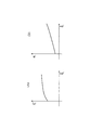
例えば、観測点Piを通過するときのモータ回転速度がω1であったとすると、図7に示すように、このモータ回転速度ω1に応じたトルク伝達効率riの平均値(r1)および偏差平方和(σ1)を取得する。
(なお、数式上では平均値r1に平均を示すオーバーラインを付しているが、明細書中の説明では、簡略化して、オーバーライン無しの平均値(r1)を使用する。)
Mahalanobis
For example, assuming that the motor rotation speed when passing through the observation point P i is ω 1 , as shown in FIG. 7, the average value (r 1 ) of the torque transmission efficiency r i according to the motor rotation speed ω 1 And the deviation sum of squares (σ 1 ).
(In the formula, an overline indicating the average is attached to the average value r 1 , but in the description in the specification, the average value (r 1 ) without overline is used in a simplified manner.)
この平均値(r1)および偏差平方和(σ1)を用いて、マハラノビス距離算出部262は、マハラノビス距離Di 2を次のように算出する。
Using this average value (r 1 ) and deviation sum of squares (σ 1 ), Mahalanobis
算出されたマハラノビス距離Di 2は、異常判定部263に送られ、異常判定部263において判定閾値Dth 2と対比される。マハラノビス距離Di 2が判定閾値以下である場合(Di 2≦Dth 2)、減速機130の動作は正常であると判定され、マハラノビス距離Di 2が判定閾値Dth 2を超える場合(Di 2>Dth 2)には減速機130に異常があると判定される。
The calculated Mahalanobis distance D i 2 is sent to the
このような第2実施形態によれば、上記第1実施形態の効果に加えて次の効果を奏する。
(5)本実施形態によれば、回転速度によって粘性摩擦が変化するような減速機に対しても信頼性のある異常診断が可能になる。
According to the second embodiment as described above, the following effects are obtained in addition to the effects of the first embodiment.
(5) According to the present embodiment, a reliable abnormality diagnosis is possible even for a reduction gear whose viscous friction changes depending on the rotational speed.
(変形例)
上記実施形態において、観測点の個数は、360度を45度ずつ分割した8個としたが、分割を多くして観測点を細かく設定した方がよいのはもちろんである。
実際のモータおよび減速機ではコギングトルクやトルクリップルなどがあり、回転角度に応じてトルクの脈動等が発生するが、分割数を多くして観測点を細かく設定することによりこれらの影響を除去することができる。
例えば、360度を30度ずつ12分割としてもよく、15度ずつ24分割して観測点を設定してもよい。
さらに、観測点を多くすることによって歯の噛み合いに起因するトルクの変動を細かく検出できるのであり、理想的には、減速機の歯数分だけ分割して、減速機のすべての歯に対応する観測点を設けることが望ましい。
(Modification)
In the above embodiment, the number of observation points is eight obtained by dividing 360 degrees by 45 degrees, but it is needless to say that the observation points should be set finely by increasing the number of divisions.
In actual motors and reducers, there are cogging torque, torque ripple, etc., and torque pulsation occurs according to the rotation angle, but these effects are eliminated by increasing the number of divisions and setting observation points finely be able to.
For example, 360 degrees may be divided into 12 parts by 30 degrees, or observation points may be set by dividing 24 parts by 15 degrees.
Furthermore, by increasing the number of observation points, it is possible to finely detect torque fluctuations caused by the meshing of teeth, and ideally, it is divided by the number of teeth of the reducer and corresponds to all teeth of the reducer. It is desirable to provide an observation point.
また、上記実施形態では、モータが360度回転可能であることを前提としたが、モータの回転角度範囲が360度ではなく狭い範囲に制限されていてもよい。
例えば、モータの回転角度範囲が0度から45度の範囲であれば、この45度分を適当に分割して適切な観測点を設定すればよい。
In the above embodiment, it is assumed that the motor can rotate 360 degrees, but the rotation angle range of the motor may be limited to a narrow range instead of 360 degrees.
For example, if the rotation angle range of the motor is in the range of 0 to 45 degrees, an appropriate observation point may be set by appropriately dividing this 45 degrees.
上記実施形態では、ロータリーエンコーダをモータの後段に設けて、モータの出力軸(第1出力軸)の回転角を検出するとした。
これに限らず、例えば、減速機の後段にロータリーエンコーダを設けて、減速機の出力軸(第2出力軸)の回転角を検出するようにしてもよい。
In the above embodiment, the rotary encoder is provided at the rear stage of the motor, and the rotation angle of the motor output shaft (first output shaft) is detected.
For example, a rotary encoder may be provided downstream of the speed reducer to detect the rotation angle of the output shaft (second output shaft) of the speed reducer.
なお、本発明は上記実施の形態に限られたものではなく、趣旨を逸脱しない範囲で適宜変更することが可能である。 Note that the present invention is not limited to the above-described embodiment, and can be changed as appropriate without departing from the spirit of the present invention.
100…駆動機構部、111…第1出力軸、120…モータ駆動回路、130…減速機、131…第2出力軸、140…リンク、200…減速機異常診断装置、210…ロータリーエンコーダ、220…トルクセンサ、230…演算制御部、240…タイミング制御部、241…観測点設定記憶部、242…モータ角度算出部、243…タイミング指示部、250…観測データ処理部、251…モータトルク算出部、252…観測トルク算出部、253…伝達効率算出部、253…トルク伝達効率算出部、260…統計処理部、261…正常時データ記憶部、262…マハラノビス距離算出部、263…異常判定部、264…回転速度算出部、265…正常時データ記憶部、300…減速機異常診断装置。
DESCRIPTION OF
Claims (6)
前記モータまたは前記減速機の出力軸の回転角度範囲内で複数設定された観測点を記憶した観測点設定記憶部と、
前記出力軸の回転角が前記観測点のいずれかに一致するごとに、その観測点におけるモータトルクと減速後トルクとの比をトルク伝達効率として算出するトルク伝達効率算出部と、
前記算出されたトルク伝達効率と正常時データ値との統計的距離を算出する統計距離算出部と、
前記算出された統計的距離を所定閾値と対比して前記統計的距離が前記所定閾値を超えた場合に異常判定を行う異常判定部と、を備える
ことを特徴とする減速機異常診断装置。 A reduction gear abnormality diagnosis device for diagnosing abnormality of a reduction gear that outputs by reducing the rotation speed of a motor,
An observation point setting storage unit storing a plurality of observation points set within a rotation angle range of the output shaft of the motor or the speed reducer;
A torque transmission efficiency calculating unit that calculates a ratio of the motor torque and the post-deceleration torque at the observation point as torque transmission efficiency each time the rotation angle of the output shaft matches any of the observation points;
A statistical distance calculator for calculating a statistical distance between the calculated torque transmission efficiency and a normal data value;
An reducer abnormality diagnosing device, comprising: an abnormality determining unit that compares the calculated statistical distance with a predetermined threshold and performs an abnormality determination when the statistical distance exceeds the predetermined threshold.
前記統計距離算出部は、マハラノビス距離を統計的距離として算出する
ことを特徴とする減速機異常診断装置。 In the speed reducer abnormality diagnosis device according to claim 1,
The statistical distance calculation unit calculates a Mahalanobis distance as a statistical distance.
前記モータの後段に設けられこのモータの出力軸の回転を検出するロータリーエンコーダと、
前記ロータリーエンコーダからのセンサ信号に基づいて前記出力軸の回転角を算出するモータ角度算出部と、
前記算出された回転角を前記観測点に対比して、回転角が前記観測点に一致したときにタイミング信号を出力するタイミング指示部と、を備え、
前記トルク伝達効率算出部および統計距離算出部は、前記タイミング信号を受信したときに処理動作を開始する
ことを特徴とする減速機異常診断装置。 In the speed reducer abnormality diagnosis device according to claim 1 or claim 2,
A rotary encoder provided at a subsequent stage of the motor for detecting the rotation of the output shaft of the motor;
A motor angle calculation unit for calculating a rotation angle of the output shaft based on a sensor signal from the rotary encoder;
A timing indicator that outputs the timing signal when the rotation angle coincides with the observation point by comparing the calculated rotation angle with the observation point;
The torque transmission efficiency calculating unit and the statistical distance calculating unit start a processing operation when the timing signal is received.
前記出力軸の回転速度を算出する回転速度算出部を備え、
前記正常値データは、前記出力軸の回転速度に応じて変化するように用意されており、
前記統計距離算出部は、前記トルク伝達効率算出部にて算出されたトルク伝達効率と、前記算出された回転速度に応じた正常時データと、を用いて統計的距離を算出する
ことを特徴とする減速機異常診断装置。 In the speed reducer abnormality diagnosis device according to any one of claims 1 to 3,
A rotation speed calculation unit for calculating the rotation speed of the output shaft;
The normal value data is prepared so as to change according to the rotation speed of the output shaft,
The statistical distance calculation unit calculates a statistical distance using the torque transmission efficiency calculated by the torque transmission efficiency calculation unit and normal data corresponding to the calculated rotation speed. Reducer abnormality diagnosis device.
前記観測点は、減速機のすべての歯に対応して設けられている
ことを特徴とする減速機異常診断装置。 In the speed reducer abnormality diagnosis device according to any one of claims 1 to 4,
The observation point is provided corresponding to all teeth of the speed reducer.
前記モータまたは前記減速機の出力軸の回転角度範囲内で観測点を複数設定し、
前記出力軸の回転角が前記観測点のいずれかに一致するごとに、その観測点におけるモータトルクと減速後トルクとの比をトルク伝達効率として算出し、
前記算出されたトルク伝達効率と正常時データ値との統計的距離を算出し、
前記算出された統計的距離を所定閾値と対比して前記統計的距離が前記所定閾値を超えた場合に異常判定を行う
ことを特徴とする減速機異常診断方法。 A reduction gear abnormality diagnosis method for diagnosing an abnormality of a reduction gear that outputs by reducing the rotation speed of a motor,
Set a plurality of observation points within the rotation angle range of the output shaft of the motor or the speed reducer,
Each time the rotation angle of the output shaft matches any of the observation points, the ratio of the motor torque and the post-deceleration torque at the observation point is calculated as the torque transmission efficiency,
Calculating a statistical distance between the calculated torque transmission efficiency and a normal data value;
A reduction gear abnormality diagnosis method comprising: comparing the calculated statistical distance with a predetermined threshold value and performing an abnormality determination when the statistical distance exceeds the predetermined threshold value.
Priority Applications (1)
| Application Number | Priority Date | Filing Date | Title |
|---|---|---|---|
| JP2011057849A JP5482699B2 (en) | 2011-03-16 | 2011-03-16 | Reduction gear abnormality diagnosis device and reduction gear abnormality diagnosis method |
Applications Claiming Priority (1)
| Application Number | Priority Date | Filing Date | Title |
|---|---|---|---|
| JP2011057849A JP5482699B2 (en) | 2011-03-16 | 2011-03-16 | Reduction gear abnormality diagnosis device and reduction gear abnormality diagnosis method |
Publications (2)
| Publication Number | Publication Date |
|---|---|
| JP2012194035A true JP2012194035A (en) | 2012-10-11 |
| JP5482699B2 JP5482699B2 (en) | 2014-05-07 |
Family
ID=47086073
Family Applications (1)
| Application Number | Title | Priority Date | Filing Date |
|---|---|---|---|
| JP2011057849A Expired - Fee Related JP5482699B2 (en) | 2011-03-16 | 2011-03-16 | Reduction gear abnormality diagnosis device and reduction gear abnormality diagnosis method |
Country Status (1)
| Country | Link |
|---|---|
| JP (1) | JP5482699B2 (en) |
Cited By (26)
| Publication number | Priority date | Publication date | Assignee | Title |
|---|---|---|---|---|
| CN103728132A (en) * | 2013-12-19 | 2014-04-16 | 杭州嘉诚机械有限公司 | Reduction box transmission efficiency/fault detection system and method |
| CN104614166A (en) * | 2015-01-29 | 2015-05-13 | 西北工业大学 | Method for identifying failure state of rotor vibration signal of aircraft engine |
| CN104807631A (en) * | 2014-01-23 | 2015-07-29 | 天津职业技术师范大学 | Precision speed reducer transmission error test system |
| CN105021377A (en) * | 2014-04-15 | 2015-11-04 | 江苏神通阀门股份有限公司 | Moveable torque testing device |
| CN105606361A (en) * | 2016-01-28 | 2016-05-25 | 上海交通大学 | Adjustable gap experiment platform |
| CN105806614A (en) * | 2016-03-07 | 2016-07-27 | 大唐淮南洛河发电厂 | Embedded dual server based failure diagnosis method and system for rotation machines in heat-engine plant |
| JP6144404B1 (en) * | 2016-12-27 | 2017-06-07 | 川崎重工業株式会社 | Reduction gear failure diagnosis device, failure diagnosis method, and mechanical device including the failure diagnosis device |
| CN106855462A (en) * | 2016-12-19 | 2017-06-16 | 北京航空航天大学 | A kind of Combined Loading device for robot joint speed reducer performance test |
| CN107101827A (en) * | 2017-06-19 | 2017-08-29 | 苏州微著设备诊断技术有限公司 | A kind of low-speed heavy-loaded gear crack fault online test method |
| WO2017213183A1 (en) * | 2016-06-07 | 2017-12-14 | 三菱電機株式会社 | Abnormality diagnosis device and abnormality diagnosis method |
| CN107677477A (en) * | 2017-10-26 | 2018-02-09 | 苏州乐轩科技有限公司 | The damage detecting system and damage method for detecting of motor and deceleration device |
| WO2018093587A1 (en) * | 2016-11-03 | 2018-05-24 | Robert Bosch Automotive Steering Llc | Detection of high friction, in an electrical power steering gear, due to rust |
| JP2018202553A (en) * | 2017-06-05 | 2018-12-27 | マツダ株式会社 | State diagnostic method and state diagnostic device for speed reducer |
| JP2019024305A (en) * | 2018-08-10 | 2019-02-14 | 株式会社安川電機 | Motor control system |
| WO2019038854A1 (en) * | 2017-08-23 | 2019-02-28 | 三菱電機株式会社 | Vehicle-mounted fuel pump control device |
| CN109974790A (en) * | 2019-04-28 | 2019-07-05 | 机械工业仪器仪表综合技术经济研究所 | It can carry out the speed reducer standard testing bed and operating method of predictive maintenance |
| JP2020025461A (en) * | 2019-11-11 | 2020-02-13 | 株式会社安川電機 | Motor control system |
| JP2020025462A (en) * | 2019-11-11 | 2020-02-13 | 株式会社安川電機 | Motor control system |
| US10663518B2 (en) | 2016-02-23 | 2020-05-26 | Kabushiki Kaisha Yaskawa Denki | Abnormality determining apparatus, abnormality determining method, and abnormality determining system |
| CN112051060A (en) * | 2020-09-06 | 2020-12-08 | 王心成 | Comprehensive test platform for precision speed reducer |
| CN112326234A (en) * | 2020-11-27 | 2021-02-05 | 北京工业大学 | Input fixing structure of harmonic reducer comprehensive performance test equipment |
| CN112326233A (en) * | 2020-11-27 | 2021-02-05 | 北京工业大学 | Harmonic reducer comprehensive performance test bed |
| CN114813117A (en) * | 2022-04-13 | 2022-07-29 | 昆明理工大学 | Fault diagnosis method and device for RV reducer |
| WO2022218291A1 (en) * | 2021-04-16 | 2022-10-20 | 安徽理工大学 | Test bench for factory quality comprehensive performance quantitative testing of rv reducer and detection method therefor |
| US11507044B2 (en) | 2016-06-07 | 2022-11-22 | Mitsubishi Electric Corporation | Abnormality diagnosis apparatus and abnormality diagnosis method |
| WO2023007634A1 (en) * | 2021-07-28 | 2023-02-02 | ファナック株式会社 | Robot system |
Families Citing this family (2)
| Publication number | Priority date | Publication date | Assignee | Title |
|---|---|---|---|---|
| CN105758633B (en) * | 2016-02-26 | 2018-03-23 | 中国航空工业集团公司上海航空测控技术研究所 | A kind of method for assessing each part health status of gear-box |
| CN106950058A (en) * | 2017-02-28 | 2017-07-14 | 哈尔滨理工大学 | Gear Fault Diagnosis device based on load torque method for feature analysis |
-
2011
- 2011-03-16 JP JP2011057849A patent/JP5482699B2/en not_active Expired - Fee Related
Cited By (32)
| Publication number | Priority date | Publication date | Assignee | Title |
|---|---|---|---|---|
| CN103728132A (en) * | 2013-12-19 | 2014-04-16 | 杭州嘉诚机械有限公司 | Reduction box transmission efficiency/fault detection system and method |
| CN104807631A (en) * | 2014-01-23 | 2015-07-29 | 天津职业技术师范大学 | Precision speed reducer transmission error test system |
| CN105021377A (en) * | 2014-04-15 | 2015-11-04 | 江苏神通阀门股份有限公司 | Moveable torque testing device |
| CN104614166A (en) * | 2015-01-29 | 2015-05-13 | 西北工业大学 | Method for identifying failure state of rotor vibration signal of aircraft engine |
| CN105606361A (en) * | 2016-01-28 | 2016-05-25 | 上海交通大学 | Adjustable gap experiment platform |
| US10663518B2 (en) | 2016-02-23 | 2020-05-26 | Kabushiki Kaisha Yaskawa Denki | Abnormality determining apparatus, abnormality determining method, and abnormality determining system |
| CN105806614A (en) * | 2016-03-07 | 2016-07-27 | 大唐淮南洛河发电厂 | Embedded dual server based failure diagnosis method and system for rotation machines in heat-engine plant |
| US11507044B2 (en) | 2016-06-07 | 2022-11-22 | Mitsubishi Electric Corporation | Abnormality diagnosis apparatus and abnormality diagnosis method |
| WO2017213183A1 (en) * | 2016-06-07 | 2017-12-14 | 三菱電機株式会社 | Abnormality diagnosis device and abnormality diagnosis method |
| JPWO2017213183A1 (en) * | 2016-06-07 | 2018-11-29 | 三菱電機株式会社 | Abnormality diagnosis apparatus and abnormality diagnosis method |
| US11780492B2 (en) | 2016-11-03 | 2023-10-10 | Robert Bosch Automotive Steering Llc | Detection of high friction, in an electrical power steering gear, due to rust |
| WO2018093587A1 (en) * | 2016-11-03 | 2018-05-24 | Robert Bosch Automotive Steering Llc | Detection of high friction, in an electrical power steering gear, due to rust |
| CN106855462B (en) * | 2016-12-19 | 2019-03-26 | 北京航空航天大学 | A kind of Combined Loading device for robot joint speed reducer performance test |
| CN106855462A (en) * | 2016-12-19 | 2017-06-16 | 北京航空航天大学 | A kind of Combined Loading device for robot joint speed reducer performance test |
| WO2018124182A1 (en) * | 2016-12-27 | 2018-07-05 | 川崎重工業株式会社 | Fault diagnosis device and fault diagnosis method for speed reducers, and mechanical device comprising same fault diagnosis device |
| JP2018105782A (en) * | 2016-12-27 | 2018-07-05 | 川崎重工業株式会社 | Fault diagnosis device of reduction gear, fault diagnosis method, and machinery including fault diagnosis device |
| JP6144404B1 (en) * | 2016-12-27 | 2017-06-07 | 川崎重工業株式会社 | Reduction gear failure diagnosis device, failure diagnosis method, and mechanical device including the failure diagnosis device |
| JP2018202553A (en) * | 2017-06-05 | 2018-12-27 | マツダ株式会社 | State diagnostic method and state diagnostic device for speed reducer |
| CN107101827B (en) * | 2017-06-19 | 2019-05-21 | 苏州微著设备诊断技术有限公司 | A kind of low-speed heavy-loaded gear crack fault online test method |
| CN107101827A (en) * | 2017-06-19 | 2017-08-29 | 苏州微著设备诊断技术有限公司 | A kind of low-speed heavy-loaded gear crack fault online test method |
| WO2019038854A1 (en) * | 2017-08-23 | 2019-02-28 | 三菱電機株式会社 | Vehicle-mounted fuel pump control device |
| CN107677477A (en) * | 2017-10-26 | 2018-02-09 | 苏州乐轩科技有限公司 | The damage detecting system and damage method for detecting of motor and deceleration device |
| JP2019024305A (en) * | 2018-08-10 | 2019-02-14 | 株式会社安川電機 | Motor control system |
| CN109974790A (en) * | 2019-04-28 | 2019-07-05 | 机械工业仪器仪表综合技术经济研究所 | It can carry out the speed reducer standard testing bed and operating method of predictive maintenance |
| JP2020025462A (en) * | 2019-11-11 | 2020-02-13 | 株式会社安川電機 | Motor control system |
| JP2020025461A (en) * | 2019-11-11 | 2020-02-13 | 株式会社安川電機 | Motor control system |
| CN112051060A (en) * | 2020-09-06 | 2020-12-08 | 王心成 | Comprehensive test platform for precision speed reducer |
| CN112326234A (en) * | 2020-11-27 | 2021-02-05 | 北京工业大学 | Input fixing structure of harmonic reducer comprehensive performance test equipment |
| CN112326233A (en) * | 2020-11-27 | 2021-02-05 | 北京工业大学 | Harmonic reducer comprehensive performance test bed |
| WO2022218291A1 (en) * | 2021-04-16 | 2022-10-20 | 安徽理工大学 | Test bench for factory quality comprehensive performance quantitative testing of rv reducer and detection method therefor |
| WO2023007634A1 (en) * | 2021-07-28 | 2023-02-02 | ファナック株式会社 | Robot system |
| CN114813117A (en) * | 2022-04-13 | 2022-07-29 | 昆明理工大学 | Fault diagnosis method and device for RV reducer |
Also Published As
| Publication number | Publication date |
|---|---|
| JP5482699B2 (en) | 2014-05-07 |
Similar Documents
| Publication | Publication Date | Title |
|---|---|---|
| JP5482699B2 (en) | Reduction gear abnormality diagnosis device and reduction gear abnormality diagnosis method | |
| US20080215292A1 (en) | Method of diagnosing abnormality of reduction gear and apparatus for carry out the method | |
| JP5009791B2 (en) | Intelligent drive | |
| JP6584662B2 (en) | Abnormality diagnosis apparatus and abnormality diagnosis method | |
| WO2018124182A1 (en) | Fault diagnosis device and fault diagnosis method for speed reducers, and mechanical device comprising same fault diagnosis device | |
| KR101889248B1 (en) | Fault Diagnosis Device and Fault Diagnosis Method | |
| TWI452822B (en) | Apparatus for controlling a motor | |
| EP3693140A1 (en) | Method for estimating position where abnormality was generated, and program for executing estimation of position where abnormality was generated | |
| KR102419726B1 (en) | A device for diagnosing deterioration of a mechanical device, a method for diagnosing deterioration of a mechanical device executed by the device for diagnosing deterioration of a mechanical device, and a method for diagnosing deterioration of a mechanical device | |
| KR20150032874A (en) | Method and apparatus for combining torque and angle representations | |
| JP7275008B2 (en) | Diagnostic device, motor drive device and diagnostic method | |
| JP4073902B2 (en) | Abnormality and deterioration diagnosis method and apparatus for motor-operated valve device | |
| CN111113119A (en) | Feed shaft abnormality determination system and worm wheel abnormality determination system | |
| US11268884B2 (en) | Abnormality diagnostic method and abnormality diagnostic device for feed axis device | |
| WO2019167180A1 (en) | Abnormality type determining device and abnormality type determining method | |
| JP2019155498A (en) | Robot control device, abnormality diagnosis method, and abnormality diagnosis program | |
| JP7358049B2 (en) | Control methods, programs, recording media, robot systems, and article manufacturing methods | |
| JP5822794B2 (en) | Motor control device | |
| JP2019195863A (en) | Robot control device, maintenance management method and maintenance management program | |
| JP2006158031A (en) | Motor controller and control method for the same | |
| JP2009196302A (en) | Twin screw kneading extruder and load torque calculation method in twin screw kneading extruder | |
| WO2017216938A1 (en) | Servo control diagnostic system | |
| JP2018205895A (en) | Movement precision monitoring system and rotation table provided with movement precision monitoring function, machine tool and nc apparatus | |
| KR101223756B1 (en) | Belt and motor diagnosis system using encoder | |
| JP2010066188A (en) | Method and device for diagnosing failure of rotating body of industrial vehicle |
Legal Events
| Date | Code | Title | Description |
|---|---|---|---|
| A621 | Written request for application examination |
Free format text: JAPANESE INTERMEDIATE CODE: A621 Effective date: 20131017 |
|
| A977 | Report on retrieval |
Free format text: JAPANESE INTERMEDIATE CODE: A971007 Effective date: 20140114 |
|
| TRDD | Decision of grant or rejection written | ||
| A01 | Written decision to grant a patent or to grant a registration (utility model) |
Free format text: JAPANESE INTERMEDIATE CODE: A01 Effective date: 20140121 |
|
| A61 | First payment of annual fees (during grant procedure) |
Free format text: JAPANESE INTERMEDIATE CODE: A61 Effective date: 20140203 |
|
| R151 | Written notification of patent or utility model registration |
Ref document number: 5482699 Country of ref document: JP Free format text: JAPANESE INTERMEDIATE CODE: R151 |
|
| LAPS | Cancellation because of no payment of annual fees |