JP2012192809A - Air conditioning structure of vehicle battery unit - Google Patents
Air conditioning structure of vehicle battery unit Download PDFInfo
- Publication number
- JP2012192809A JP2012192809A JP2011057443A JP2011057443A JP2012192809A JP 2012192809 A JP2012192809 A JP 2012192809A JP 2011057443 A JP2011057443 A JP 2011057443A JP 2011057443 A JP2011057443 A JP 2011057443A JP 2012192809 A JP2012192809 A JP 2012192809A
- Authority
- JP
- Japan
- Prior art keywords
- battery unit
- vehicle
- supply duct
- width direction
- air
- Prior art date
- Legal status (The legal status is an assumption and is not a legal conclusion. Google has not performed a legal analysis and makes no representation as to the accuracy of the status listed.)
- Granted
Links
Images

Abstract
Description
ここに開示する技術は、車室フロアの下側にバッテリユニットが搭載された車両のバッテリユニット空調構造に関する。 The technology disclosed herein relates to a battery unit air conditioning structure for a vehicle in which a battery unit is mounted on the lower side of a passenger compartment floor.
一般に、電気自動車等の電動車両では、複数のバッテリモジュールが車室フロアの下側にユニット化された状態で搭載される。例えば特許文献1、2には、車室フロアの下側に取り付けたバッテリユニット内に、複数のバッテリモジュールを収容した構成が記載されている。
Generally, in an electric vehicle such as an electric vehicle, a plurality of battery modules are mounted in a united state below the passenger compartment floor. For example,
ところで、バッテリモジュールは、温度が過度に上昇したり、過度に低下したりすると、バッテリ性能が低下してしまうことから、バッテリユニット内に収容している各バッテリモジュールに対しては、その冷却や暖機といった温度調整が必要になる。特許文献1、2に記載されている電気自動車では、バッテリユニット内に車室用空調装置からの空調空気を導入し、それによって、各バッテリモジュールの温度調整を行うようにしている。より具体的には、バッテリユニットの前部に空調空気の導入口を形成する一方、バッテリユニットの後部に空気の排気口を形成しており、これによって、導入口からバッテリユニット内に導入した空調空気を、複数のバッテリモジュールとの間で熱交換を行わせながら車体前後方向の後方へと流して、排気口から排出するようにしている。
By the way, since the battery performance deteriorates when the temperature rises excessively or falls excessively, the battery modules housed in the battery unit are not cooled or cooled. Temperature adjustment such as warm-up is required. In the electric vehicles described in
ところが、バッテリユニット内に収容された複数のバッテリモジュールは、その温度状態が均一であることが望ましいが、前記の各特許文献に記載された構成では、バッテリユニットの前部から導入した空調空気を車体前後方向の一方向に流して、後部から排気するようにしているため、バッテリユニット内を通過している間に、空調空気の温度は次第に上昇又は低下してしまうことになる。その結果、バッテリユニット内において車体前後方向の前側に配置しているバッテリモジュールは空調空気によって温度調整が十分に行われる一方で、バッテリユニット内において車体前後方向の後側に配置しているバッテリモジュールは、空調空気の温度が既に上昇又は低下してしまっていることから、温度調整が十分に行われない。このことによって、複数のバッテリモジュール間に温度差が生じ、バッテリ性能が低下する虞がある。 However, it is desirable that the plurality of battery modules accommodated in the battery unit have a uniform temperature state. However, in the configuration described in each of the above patent documents, the conditioned air introduced from the front of the battery unit is not used. Since the air flows in one direction in the longitudinal direction of the vehicle body and is exhausted from the rear portion, the temperature of the conditioned air gradually increases or decreases while passing through the battery unit. As a result, the battery module disposed on the front side in the vehicle body front-rear direction in the battery unit is sufficiently temperature-adjusted by the conditioned air, while the battery module disposed on the rear side in the vehicle body front-rear direction in the battery unit. Since the temperature of the conditioned air has already increased or decreased, temperature adjustment is not sufficiently performed. As a result, a temperature difference occurs between the plurality of battery modules, and the battery performance may be reduced.
特に、内燃機関を搭載した既存の車両を電気自動車に改造したコンバージョンEV等では、車体構造を大幅に変更することができないため、バッテリモジュールの配置が大きく制約される場合がある。例えばバッテリユニット内で前側位置と後側位置とに、バッテリモジュールを分散して配置しなければならない場合もある。その場合に、前述したように、バッテリモジュールの温度調整に関し、バッテリユニットの前部から導入した空調空気を車体前後方向の一方向に流して、後部から排気する構成を採用したのでは、後側に配置したバッテリモジュールの温度調整が益々行われ難くなり、複数のバッテリモジュール間の温度差がさらに拡大してしまうことが予想される。 In particular, in a conversion EV or the like in which an existing vehicle equipped with an internal combustion engine is remodeled into an electric vehicle, the structure of the vehicle body cannot be significantly changed, so that the arrangement of the battery module may be greatly restricted. For example, the battery modules may need to be distributed and arranged at the front side position and the rear side position in the battery unit. In that case, as described above, with regard to the temperature adjustment of the battery module, the configuration in which the conditioned air introduced from the front part of the battery unit flows in one direction in the vehicle longitudinal direction and exhausts from the rear part is adopted. It is expected that the temperature adjustment of the battery modules arranged in the battery will be increasingly difficult, and the temperature difference between the plurality of battery modules will be further increased.
ここに開示する技術は、かかる点に鑑みてなされたものであり、その目的とするところは、車室フロアの下側でバッテリユニットが車体部材に結合された車両において、バッテリユニット内に収容した複数のバッテリモジュールの温度調整を均一化することにある。 The technology disclosed herein has been made in view of such a point, and the object is to accommodate the battery unit in the battery unit in a vehicle in which the battery unit is coupled to the vehicle body member below the passenger compartment floor. The purpose is to make the temperature adjustment of a plurality of battery modules uniform.
ここに開示する技術は、車室フロアの下側に、複数のバッテリモジュールと電気部品とを収容するバッテリユニットが搭載された車両用バッテリユニットの空調構造に関する。 The technology disclosed herein relates to an air conditioning structure for a vehicle battery unit in which a battery unit that houses a plurality of battery modules and electrical components is mounted below a passenger compartment floor.
この車両用バッテリユニットの空調構造では、前記車室フロアは、フロントフロア部と、当該フロントフロア部に対し車体前後方向の後側に配設されたリヤフロア部と、を含み、前記バッテリユニットは、前記フロントフロア部の下側に配設されかつ、前記バッテリモジュールを内部に収容する第1収容部と、前記リヤフロア部の下側に配設されて、その内部が前記第1収容部内に連通していると共に、前記バッテリモジュールを内部に収容する第2収容部と、を含み、前記バッテリユニットにおける車体前後方向の中間部には、車室用空調装置からの空調空気をユニット内部に導入する導入口と、導入された空調空気を前記第1収容部の方と前記第2収容部の方とに分配する分配部と、が設けられ、前記分配部には、前記バッテリユニットの車幅方向中央部において前記分配部から前方に向かって延びることにより、前記導入された空調空気を前記第1収容部のバッテリモジュールに供給する第1供給ダクトと、前記バッテリユニットの車幅方向中央部において前記分配部から後方に向かって延びることにより、前記導入された空調空気を前記第2収容部のバッテリモジュールに供給する第2供給ダクトとが、それぞれ接続されている。 In the air conditioning structure of the vehicle battery unit, the vehicle compartment floor includes a front floor portion, and a rear floor portion disposed on the rear side in the vehicle longitudinal direction with respect to the front floor portion, and the battery unit includes: A first accommodating portion that is disposed below the front floor portion and accommodates the battery module therein, and is disposed below the rear floor portion, and the interior communicates with the first accommodating portion. And a second housing portion for housing the battery module therein, and introducing the conditioned air from the vehicle interior air conditioner into the interior of the unit in the vehicle body longitudinal direction of the battery unit. And a distribution unit that distributes the introduced conditioned air to the first storage unit and the second storage unit, and the distribution unit includes the battery unit. A first supply duct that supplies the introduced conditioned air to the battery module of the first housing portion by extending forward from the distribution portion in the vehicle width direction center, and the vehicle width direction center of the battery unit And a second supply duct for supplying the introduced conditioned air to the battery module of the second housing portion by extending rearward from the distribution portion in the portion.
この構成によると、バッテリユニットは、フロントフロア部の下側に配設された第1収容部と、リヤフロア部の下側に配設された第2収容部とを含んでいて、第1収容部に収納されたバッテリモジュールは、車体前後方向に対し、相対的に前側に配置され、第2収容部に収納されたバッテリモジュールは、相対的に後側に配置されることになる。つまりこの構成では、バッテリユニット内で複数のバッテリモジュールを前側と後側とに分散して配置している。 According to this configuration, the battery unit includes the first housing portion disposed below the front floor portion, and the second housing portion disposed below the rear floor portion. The battery module housed in the battery housing is disposed on the front side relative to the longitudinal direction of the vehicle body, and the battery module housed in the second housing portion is disposed on the rear side relatively. That is, in this configuration, a plurality of battery modules are distributed and arranged on the front side and the rear side in the battery unit.
このように分散配置されたバッテリモジュールに対して、車室用空調装置からの空調空気をバッテリユニット内に導入するための導入口は、バッテリユニットにおける車体前後方向の中間部に設けられている。ここで、「バッテリユニットにおける車体前後方向の中間部」に導入口を設けるとは、第1収容部と第2収容部との中間位置に導入口を設けてもよいし、第1収容部及び第2収容部の前後方向の大きさ如何によって、導入口が第1収容部内に設けられる場合や、第2収容部内に設けられる場合もあり得る。いずれにおいても導入口は、第1収容部のバッテリユニットと第2収容部のバッテリユニットの間の位置の近傍に位置する。 With respect to the battery modules distributed in this manner, an introduction port for introducing the conditioned air from the passenger compartment air conditioner into the battery unit is provided in an intermediate portion of the battery unit in the front-rear direction of the vehicle body. Here, “providing the introduction port at the“ intermediate portion of the battery unit in the longitudinal direction of the vehicle body ”” may mean providing the introduction port at an intermediate position between the first accommodation unit and the second accommodation unit, Depending on the size of the second housing part in the front-rear direction, the introduction port may be provided in the first housing part or in the second housing part. In any case, the introduction port is located in the vicinity of the position between the battery unit of the first housing part and the battery unit of the second housing part.
バッテリユニットにおける車体前後方向の中間部にはまた、導入口から導入された空調空気を、第1収容部の方と第2収容部の方とに分配する分配部が設けられていると共に、その分配部には、車幅方向中央部において前方に向かって延びる第1供給ダクトと、車幅方向中央部において後方に向かって延びる第2供給ダクトと、がそれぞれ連結されている。従って、バッテリユニットにおける中間部の導入口から導入された空調空気は、分配部から第1供給ダクトを通じて第1収容部に収容されているバッテリモジュールに供給されると共に、分配部から第2供給ダクトを通じて第2収容部に収容されているバッテリモジュールに供給される。こうして、この構成では、第1収容部に収容されている前側のバッテリモジュールと、第2収容部に収容されている後側のバッテリモジュールとのそれぞれについて、導入口から導入した空調空気を直接的に供給することが可能になる。このことは、バッテリモジュールの前部から取り入れた空調空気を、複数のバッテリモジュールとの間で順に熱交換を行いながら車体前後方向の後方へと流し、バッテリモジュールの後部から排出する従来の構成とは異なり、前側のバッテリモジュールに供給する空調空気の温度と、後側のバッテリモジュールに供給する空調空気の温度とを実質的に同じ温度にする。その結果、第1及び第2収容部のそれぞれに収容されているバッテリモジュールの温度調整を、均一化することが可能になる。このことは、バッテリユニット内の複数のバッテリモジュール間の温度差を小さくする上で有利である。 In the middle part of the battery unit in the front-rear direction of the vehicle body, a distribution unit that distributes the conditioned air introduced from the introduction port to the first storage unit and the second storage unit is provided. A first supply duct extending forward in the vehicle width direction central portion and a second supply duct extending rearward in the vehicle width direction central portion are connected to the distribution portion, respectively. Therefore, the conditioned air introduced from the inlet of the intermediate part in the battery unit is supplied from the distribution part to the battery module accommodated in the first accommodation part through the first supply duct, and from the distribution part to the second supply duct. To be supplied to the battery module accommodated in the second accommodating portion. Thus, in this configuration, the conditioned air introduced from the inlet is directly applied to each of the front battery module accommodated in the first accommodating portion and the rear battery module accommodated in the second accommodating portion. It becomes possible to supply to. This is because the conditioned air taken in from the front of the battery module flows to the rear in the vehicle body front-rear direction while sequentially exchanging heat with the plurality of battery modules, and is discharged from the rear of the battery module. In contrast, the temperature of the conditioned air supplied to the front battery module and the temperature of the conditioned air supplied to the rear battery module are set to substantially the same temperature. As a result, the temperature adjustment of the battery modules accommodated in each of the first and second accommodation portions can be made uniform. This is advantageous in reducing the temperature difference between the plurality of battery modules in the battery unit.
また、第1供給ダクト及び第2供給ダクトはそれぞれ、バッテリモジュール内で車幅方向中央部に配設されているため、これら第1及び第2供給ダクトの長さを最短にしながらも、第1収容部及び第2収容部のそれぞれに収容されたバッテリモジュールに、空調空気を効率的に分配供給することが可能になる。このことは、バッテリユニットの軽量化に有利である。 In addition, since the first supply duct and the second supply duct are respectively disposed in the center part in the vehicle width direction in the battery module, the first supply duct and the second supply duct are made short while the lengths of the first supply duct and the second supply duct are minimized. It becomes possible to efficiently distribute and supply conditioned air to the battery modules housed in the housing part and the second housing part. This is advantageous for reducing the weight of the battery unit.
前記第1供給ダクト及び前記第2供給ダクトはそれぞれ、前記バッテリユニット内における相対的に上側の高さ位置に配設され、前記バッテリユニットにおける車体前後方向の中間部の車幅方向中央部であって、前記第1及び第2供給ダクトよりも下側の高さ位置には、当該バッテリユニット内の空気を排気するためのファンが配設され、前記ファンには、前記第2収容部の後方へと延びる排気ダクトが接続されている、としてもよい。 Each of the first supply duct and the second supply duct is disposed at a relatively upper height position in the battery unit, and is a middle portion in the vehicle width direction of an intermediate portion of the battery unit in the vehicle longitudinal direction. A fan for exhausting the air in the battery unit is disposed at a height position below the first and second supply ducts, and the fan is disposed behind the second housing portion. An exhaust duct extending to the side may be connected.
この構成によると、バッテリユニットの中間部の車幅方向中央部にはファンが配設されており、このファンと、第1及び第2供給ダクトとの位置関係は、第1及び第2供給ダクトが相対的に上に位置し、ファンが相対的に下に位置する。 According to this configuration, the fan is disposed in the middle portion of the battery unit in the vehicle width direction, and the positional relationship between the fan and the first and second supply ducts is the first and second supply ducts. Is relatively above and the fan is relatively below.
従って、前述したように、導入口から導入されて、相対的に上側に配置された第1供給ダクトを通じて第1収容部に収容されているバッテリモジュールに供給されると共に、同じく相対的に上側に配置された第2供給ダクトを通じて第2収容部に収容されているバッテリモジュールに供給された空調空気は、それらのバッテリモジュールとの間で熱交換を行って、バッテリモジュールの温度調整を行った後に、バッテリユニット内を循環するように流れて、前後方向の中間部の車幅方向中央部であって、相対的に下側に配置されたファンへと至るようになる。そうして、その空調空気は、ファンに吸い込まれ、そこに接続されると共に車幅方向の中央部で後方へと延びる排気ダクトを通じて、バッテリモジュールの外に排気される。つまり、前後方向の中間部であって車幅方向中央部において、上側には導入口、分配部並びに、そこから延びる第1供給ダクト及び第2供給ダクトを設ける一方で、下側に空調空気の排気用のファンを配置することは、バッテリユニット内で空調空気を循環させることを可能にするから、各バッテリモジュールに対し空調空気を適切にかつ効果的に供給することを実現し、各バッテリモジュールの温度調整の均一化にさらに有利になる。 Therefore, as described above, the battery module is introduced from the introduction port and supplied to the battery module housed in the first housing portion through the first supply duct disposed relatively on the upper side. After the conditioned air supplied to the battery modules accommodated in the second accommodating portion through the arranged second supply duct exchanges heat with the battery modules and adjusts the temperature of the battery modules. Then, the air flows in a circulating manner in the battery unit, and reaches a fan disposed in the vehicle width direction central portion of the intermediate portion in the front-rear direction and relatively on the lower side. Then, the conditioned air is sucked into the fan, connected to the fan, and exhausted out of the battery module through an exhaust duct extending rearward at the center in the vehicle width direction. In other words, in the middle part in the vehicle width direction in the front-rear direction, the upper side is provided with the introduction port, the distribution part, and the first supply duct and the second supply duct extending therefrom, while the lower side is provided with conditioned air. Arranging the fan for exhaust makes it possible to circulate the conditioned air in the battery unit, so that it is possible to supply the conditioned air appropriately and effectively to each battery module. It is further advantageous to make the temperature adjustment uniform.
また、ファンを、バッテリユニットの前後方向でかつ車幅方向の中央部に配置することによって、そこに接続される排気ダクトの長さは最短化するため、バッテリユニットの軽量化に有利になる。 In addition, by disposing the fan in the front-rear direction of the battery unit and in the center in the vehicle width direction, the length of the exhaust duct connected thereto is minimized, which is advantageous for reducing the weight of the battery unit.
前記第1収容部のバッテリモジュールは、車幅方向中央部において車体前後方向に延びて配置された前記第1供給ダクトに対し車幅方向の両側外方位置に配置され、前記第1収容部には、前記バッテリモジュールに対し車幅方向の内方位置であって、当該バッテリモジュールと略同じ高さ位置に、前記電気部品が配置され、前記第1供給ダクトは、前記バッテリモジュール及び電気部品よりも上側の高さ位置に配設されかつ、車幅方向の内方側から両側の外方に向かって前記空調空気を吹き出すように構成されている、としてもよい。 The battery module of the first housing part is disposed at an outer position on both sides in the vehicle width direction with respect to the first supply duct disposed to extend in the vehicle front-rear direction at a vehicle width direction central part. Is an inward position in the vehicle width direction with respect to the battery module, and the electric component is disposed at substantially the same height position as the battery module, and the first supply duct is formed from the battery module and the electric component. Also, the conditioned air may be blown out from the inner side in the vehicle width direction toward the outer side on both sides.
第1供給ダクトから、車幅方向の両側外方に向かって空調空気を吹き出すことによって、空調空気は、車幅方向の内側から外側にかつ、上側から下側に向かって流れて、バッテリモジュールに供給される。そうしてバッテリモジュールとの間で熱交換を行い、バッテリモジュールの温度調整が行われる。その後、空調空気は、車幅方向の外側から内側へと流れるが、この位置には電気部品が配置されているため、この電気部品の温度調整も可能になる。 By blowing out the conditioned air from the first supply duct toward both sides outward in the vehicle width direction, the conditioned air flows from the inner side to the outer side in the vehicle width direction and from the upper side to the lower side to the battery module. Supplied. Then, heat exchange is performed with the battery module, and the temperature of the battery module is adjusted. Thereafter, the conditioned air flows from the outer side to the inner side in the vehicle width direction. Since the electric component is arranged at this position, the temperature of the electric component can be adjusted.
従って、前述した第1供給ダクト、バッテリモジュール及び電気部品の配置構成は、第1収容部内で空調空気を循環させることによって、バッテリモジュール及び電気部品の、効率的な温度調整を可能にする。特に、バッテリモジュールと電気部品とを比較したときには、バッテリユニットの方が温度調整に対する要求が高いため、第1供給ダクトからの空調空気を、先にバッテリモジュールに供給し、その後に電気部品に供給することによって、バッテリモジュール及び電気部品のそれぞれを、適切に温度調整することが実現する。その結果、バッテリユニットの性能向上に有利になる。 Therefore, the arrangement configuration of the first supply duct, the battery module, and the electric component described above enables efficient temperature adjustment of the battery module and the electric component by circulating the conditioned air in the first housing portion. In particular, when comparing battery modules and electrical components, the battery unit is more demanding for temperature adjustment, so the conditioned air from the first supply duct is supplied to the battery modules first and then to the electrical components. Thus, it is possible to appropriately adjust the temperature of each of the battery module and the electrical component. As a result, it is advantageous for improving the performance of the battery unit.
前記第2収容部のバッテリモジュールは、前記第2供給ダクトに対して車幅方向の両側位置、車体前後方向の後側位置、又は、前記車幅方向の両側位置と車体前後方向の後側位置との双方に配置されている、としてもよい。こうすることで、第2収容部に収容されている各バッテリモジュールの温度調整を効率的に行うことが可能になる。 The battery module of the second housing portion may be positioned on both sides in the vehicle width direction with respect to the second supply duct, on the rear side in the vehicle longitudinal direction, or on both sides in the vehicle width direction and on the rear side in the vehicle longitudinal direction. It is good also as arrange | positioning at both. By carrying out like this, it becomes possible to perform the temperature adjustment of each battery module accommodated in the 2nd accommodating part efficiently.
前記第1供給ダクト及び第2供給ダクトの断面はそれぞれ、上下の高さよりも左右の幅が広い扁平な形状を有している、としてもよい。 The cross sections of the first supply duct and the second supply duct may each have a flat shape with a left and right width wider than a vertical height.
前述したように、バッテリモジュールは、車両フロアの下側に配設されるため、上下方向(高さ方向)に十分なスペースを確保することが困難である。第1供給ダクト及び第2供給ダクトの断面を、上下の高さよりも左右の幅が広い扁平な形状とすることは、必要なダクト断面積を確保して所望の流量を得つつも、高さ方向の省スペース化に有利である。 As described above, since the battery module is disposed below the vehicle floor, it is difficult to secure a sufficient space in the vertical direction (height direction). Making the cross sections of the first supply duct and the second supply duct into a flat shape with the width on the left and right wider than the height on the upper and lower sides ensures the necessary flow rate and obtains a desired flow rate. It is advantageous for space saving in the direction.
前記第1供給ダクトと前記第2供給ダクトとは、略等しいダクト長を有している、としてもよい。分配部から車体前後方向の前方に延びる第1供給ダクトの長さと、分配部から車体前後方向の後方に延びる第2供給ダクトの長さとを略等しくすることは、第1収容部側への空調空気の供給量と、第2収容部側への空調空気の供給量と、をそれぞれ十分に確保して、第1収容部及び第2収容部の双方に収容されたバッテリモジュールの温度調整を適切に行うことが可能になる。 The first supply duct and the second supply duct may have substantially the same duct length. The length of the first supply duct extending forward in the vehicle longitudinal direction from the distributor and the length of the second supply duct extending rearward in the vehicle longitudinal direction from the distributor are substantially equal to each other. Adequately adjust the temperature of the battery modules housed in both the first housing part and the second housing part by ensuring a sufficient amount of air supply and an amount of conditioned air supplied to the second housing part. It becomes possible to do.
前記第1供給ダクトと前記第2供給ダクトとは、略等しい断面積を有している、としてもよい。このことによっても、第1収容部側への空調空気の供給量と、第2収容部側への空調空気の供給量と、をそれぞれ十分に確保して、第1収容部及び第2収容部の双方に収容されたバッテリモジュールの温度調整を適切に行うことが可能になる。 The first supply duct and the second supply duct may have substantially the same cross-sectional area. Also by this, the supply amount of the conditioned air to the first storage unit side and the supply amount of the conditioned air to the second storage unit side are sufficiently ensured, respectively, and the first storage unit and the second storage unit Thus, it is possible to appropriately adjust the temperature of the battery modules accommodated in both of the battery modules.
前記第1供給ダクトは、互いに平行となるように車幅方向に並んで配置された右側ダクトと左側ダクトとを含んで構成されている、としてもよい。 The first supply duct may be configured to include a right duct and a left duct arranged in parallel in the vehicle width direction so as to be parallel to each other.
このことは、第1収容部に収容されている複数のバッテリモジュールに対し、均一に空調空気を供給する上で有利である。 This is advantageous in uniformly supplying the conditioned air to the plurality of battery modules housed in the first housing portion.
前記バッテリユニットの導入口は、ダッシュパネル近傍に配設された車室用空調装置から、後席乗員の足下に配設された空気吹出口まで延びるダクトに対し、接続されている、としてもよい。 The introduction port of the battery unit may be connected to a duct extending from a passenger compartment air conditioner disposed in the vicinity of the dash panel to an air outlet disposed under the rear seat passenger. .
車室フロアの下側に配置されるバッテリユニットにおいて、第1収容部側と第2収容部側との間に配置される導入口は、ダッシュパネル近傍に配設される車室用空調装置とは、車体前後方向に離れて配置される。このため、その車室用空調装置と導入口とを連結するダクトが必要になるが、車室用空調装置から後席乗員の足下に配設された空気吹出口まで延びる既存のダクトを利用することによって、新たなダクトを配設する必要がなくなる点で有利になる。 In the battery unit disposed below the passenger compartment floor, the inlet disposed between the first housing portion side and the second housing portion side includes a vehicle compartment air conditioner disposed in the vicinity of the dash panel. Are spaced apart in the longitudinal direction of the vehicle body. For this reason, a duct that connects the passenger compartment air conditioner and the introduction port is required, but an existing duct that extends from the passenger compartment air conditioner to the air outlet provided under the foot of the rear seat passenger is used. This is advantageous in that it is not necessary to install a new duct.
以上説明したように、前記車両用バッテリユニットの空調構造によると、バッテリユニットの中間部に導入口を設け、そこから前方へと延びる第1供給ダクトと、後方へと延びる第2供給ダクトとを通じて、第1収容部のバッテリモジュールと第2収容部のバッテリモジュールとのそれぞれに空調空気を供給することで、分散配置されている複数のバッテリモジュールの温度調整を均一化することができ、バッテリ性能の向上に有利になる。 As described above, according to the air conditioning structure of the vehicle battery unit, an introduction port is provided in the middle portion of the battery unit, and the first supply duct extending forward from the first supply duct and the second supply duct extending rearward are provided. By supplying conditioned air to each of the battery module of the first housing unit and the battery module of the second housing unit, the temperature adjustment of the plurality of battery modules arranged in a distributed manner can be made uniform, and the battery performance It becomes advantageous for improvement.
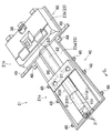
以下、車両用バッテリユニットの空調構造の実施形態を図面に基づいて説明する。尚、以下の好ましい実施形態の説明は、例示である。図1は、電動車両(本実施形態では、電気自動車であり、以下、単に車両という)の車室フロアパネル1(車室フロアを構成する)の下側の構造を示す。この車両は特に、内燃機関を搭載した既存の車両を電気自動車に改造したコンバージョンEV(Electric Vehicle)である。この車両についての前、後、左、右、上及び下を、それぞれ単に前、後、左、右、上及び下という。また、図1〜図6において、車両前側を矢印Frで示す。 Hereinafter, an embodiment of an air conditioning structure of a vehicle battery unit will be described with reference to the drawings. In addition, the following description of preferable embodiment is an illustration. FIG. 1 shows a lower structure of a vehicle compartment floor panel 1 (which constitutes a vehicle compartment floor) of an electric vehicle (in this embodiment, an electric vehicle, hereinafter simply referred to as a vehicle). This vehicle is particularly a conversion EV (Electric Vehicle) in which an existing vehicle equipped with an internal combustion engine is converted into an electric vehicle. Front, rear, left, right, up and down for this vehicle are simply referred to as front, back, left, right, up and down, respectively. Moreover, in FIGS. 1-6, the vehicle front side is shown by the arrow Fr.
前記車室フロアパネル1は、フロントフロア部1aと、該フロントフロア部1aよりも上側の高さ位置に位置するリヤフロア部1bとから構成されている。フロントフロア部1aとリヤフロア部1bとの間には、図では明示しないが、段差状のキックアップ部が設けられ、このキックアップ部により、リヤフロア部1bの高さ位置がフロントフロア部1aよりも高くなっている。
The passenger
リヤフロア部1bの上面には後席シート(図示せず)が配置されており、フロントフロア部1aの後部の上面が、該後席シートに着座した乗員の足置き場である。フロントフロア部1aの前部の上面には、運転席シート及び助手席シート(共に図示せず)が車幅方向に並んで配置される。
A rear seat (not shown) is disposed on the upper surface of the
フロントフロア部1aの前端部は、ダッシュパネル11(図5参照)の下端部に結合されている。フロントフロア部1aの車幅方向両端部は、前後方向に延びる左右一対のサイドシル12に結合されている。
The front end portion of the
フロントフロア部1aの下面における車幅方向両端部よりも車幅方向内側の部分(図示省略のフロアトンネル部の車幅方向両外側)には、前後方向に延びる左右一対のフロントフロアフレーム7が車室フロアパネル1と一体に設けられている。各フロントフロアフレーム7は、後方に向かって車幅方向内側に僅かに傾斜している。すなわち、左右のフロントフロアフレーム7の間隔が後方に向かって小さくなっている。左右のフロントフロアフレーム7の前端部は、左右のフロントサイドフレーム8の後端部に、該後端部における中空断面内に挿入された状態でそれぞれ連結されている。
A pair of left and right front floor frames 7 extending in the front-rear direction is provided on the inner side of the lower surface of the
左側のフロントサイドフレーム8の後端部と左側のサイドシル12の前端部との間、及び、右側のフロントサイドフレーム8の後端部と右側のサイドシル12の前端部との間には、フロントサイドフレーム8とサイドシル12とを結合するトルクボックス15がそれぞれ配設されている。前述の通り、フロントサイドフレーム8の後端部にフロントフロアフレーム7の前端部が挿入されていることから、トルクボックス15は、フロントフロアフレーム7とサイドシル12とを結合すると言い換えてもよい。これらトルクボックス15は、フロントサイドフレーム8の高さ位置が変化する(後側に向かって徐々に低くなる)キック部の曲げ剛性を高めて、車両の前面衝突時に該部分で折れ曲がらないようにするものである。
Between the rear end portion of the left
リヤフロア部1bの後端部は、荷室フロアパネル3の前端部に繋がる。この荷室フロアパネル3には、図には明示しないスペアタイヤパンが、下側に膨出するように形成されている。リヤフロア部1b及び荷室フロアパネル3の下面における車幅方向両端部には、前後方向に延びる左右一対のリヤサイドフレーム9がそれぞれ設けられている。左右のリヤサイドフレーム9の前端部は、前記左右のサイドシル12の後端部にそれぞれ連結されている。リヤフロア部1bの下面の後端部には、車幅方向に延びかつ前記左右のリヤサイドフレーム9同士を連結するリヤクロスメンバ10が設けられている。左右のリヤサイドフレーム9の間隔は、左右のフロントフロアフレーム7の間隔よりも大きい。
The rear end portion of the
フロントサイドフレーム8のキック部に対応する前後位置(後述のバッテリユニット21の前側)には、車幅方向に延びかつ左右の前輪サスペンションアーム17を支持するサスペンションクロスメンバ16が配設されている。図示は省略するが、サスペンションクロスメンバ16の前部は、その左右両側が左右のフロントサイドフレーム8におけるキック部よりも前側の部分にそれぞれ結合されている。また、サスペンションクロスメンバ16の後端縁は、図1に端的に示されるように、車幅方向の中央部がその両端部よりも前方に位置するように湾曲して形成されており、その車幅方向の両端部に、左右のトルクボックス15の下面にそれぞれ結合される後側結合部16b(トルクボックス15の下面から下方に延びるボルト軸が挿通される貫通孔が形成されている部分)が設けられている。
A
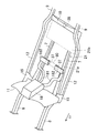
前記サスペンションクロスメンバ16の直ぐ前側には、前記車両を駆動するパワーユニット71が設けられている。このパワーユニット71は、その詳細な構成は省略するが、モータを含むモータユニット72と、該モータユニットのモータの駆動力を前輪へ伝達するための動力伝達機構(減速機構及び差動機構)を含むトランスアクスル73とが車幅方向に並ぶように一体に結合されてなるものである。モータユニットのモータ軸(つまり駆動軸)の軸心、トランスアクスル(減速機構)におけるモータ軸と連結される入力軸の軸心、及び、パワーユニット71の出力軸(つまりトランスアクスル(差動機構)の出力軸)であるジョイントシャフト(等速ジョイントを介して前輪駆動軸に連結される)の軸心は、車幅方向に延びている。また、パワーユニット71全体としての軸心も車幅方向に延びている。
A
前記パワーユニット71の車幅方向両端部は、不図示のブラケットと、ゴムブッシュを含むマウント本体とを介して、左右のフロントサイドフレーム8にそれぞれ弾性支持されている。また、図1に示すように、パワーユニット71の車幅方向の中央部の下部は、トルクロッド101を介して前記サスペンションクロスメンバ16に連結されている。パワーユニット71の車幅方向両端部における前記弾性支持により、パワーユニット71全体が車幅方向に延びる軸回りに回動(揺動)することになるが、前記トルクロッド101は、パワーユニット71全体が前記軸回りに回動し過ぎるのを規制する。トルクロッド101の前端部は、ゴムブッシュ102を介して、車幅方向に延びる軸回りに回動可能にパワーユニット71の車幅方向中央部に連結され、トルクロッド101の後端部は、ゴムブッシュ103を介して、車幅方向に延びる軸回りに回動可能にサスペンションクロスメンバ16の車幅方向中央部に連結されている。
Both ends of the
前記パワーユニット71、前記サスペンションクロスメンバ16及び後述のバッテリユニット21は、前側から後側に向かってこの順に並びかつ、詳細な図示は省略するが上下方向において互いに重なりを持って配置されている。すなわち、サスペンションクロスメンバ16とバッテリユニット21とが同じ高さ位置にあるとともに、これらがパワーユニット71の下部と同じ高さ位置(トルクロッド101と同じ高さ位置)にある。
The
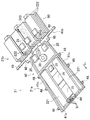
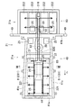
図2は、前記車室フロアパネル1の下側に搭載されたバッテリユニット21を示す。尚、以下に説明するバッテリユニット21についての前、後、左、右、上及び下は、それぞれ、バッテリユニット21が前記車両に搭載された状態での前、後、左、右、上及び下のことであり、前記車両についての前、後、左、右、上及び下と同じである。
FIG. 2 shows a
前記バッテリユニット21は、図1〜4に示すように、複数のバッテリモジュール221、222と、該複数のバッテリモジュール221、222を支持する支持部材としてのフレーム部材40、60と、上側カバー部材23及び下側カバー部材24とを有している。すなわち、車室フロアパネル1の下側に、複数のバッテリモジュール221、222がユニット化された状態で搭載されている。バッテリユニット21は、フロントフロア部1aの下側に搭載された第1収容部21aと、該第1収容部21aの後側に連続して設けられかつ前記リヤフロア部1bの下側に搭載された第2収容部21bとを有している。そうして詳しくは後述するが、このバッテリユニット21では、複数のバッテリモジュール221、222を、第1収容部21aと第2収容部21bとのそれぞれに配置することによって、前側と後側とに分散して配置している。
1-4, the
第1収容部21aは、該第1収容部21aにおける複数のバッテリモジュール221を支持するフレーム部材40を有し、第2収容部21bは、該第2収容部21bにおける複数のバッテリモジュール222を支持するフレーム部材60を有している。
The
第1収容部21aのフレーム部材40は、前部41a、後部41b及び左右一対の側部41cを含む枠状に形成されている。フレーム部材40の前部41aは車幅方向に延びて、その両端部が前後方向に延びる左右の側部41cの前端部とそれぞれ連結されている。フレーム部材40の後部41bは、左右の側部41cよりも車幅方向外側まで延びており、両側部41cは、後部41bの車幅方向中間部に連結されている。すなわち、両側部41cは、第1収容部21aの車幅方向両側の端部にそれぞれ設けられていて、第2収容部21bの前端部から前側に向かって、フロントフロアフレーム7、7に沿うように傾斜しながら延びている。フレーム部材40の前部41aには、後述するインバータ接続用端子31を支持するインバータ接続用端子支持部44が設けられている。フレーム部材40の後部41b及び両側部41cは、断面矩形で内部が中空とされている。
The
前記フレーム部材40の各側部41cの車幅方向外側の面には、側方結合部48が、所定の間隔を開けて4つずつ設けられている。各側方結合部48は、左右のフロントフロアフレーム7に、ボルトによって締結固定される。この内、最も前側の左右2つの側方結合部48は、図1に示すように、フロントフロアフレーム7とフロントサイドフレーム8との連結部(フロントフロアフレーム7とフロントサイドフレーム8とが重なり合った部分であって、トルクボックス15の近傍に位置する)に固定される。すなわち、最も前側の側方結合部48は、フロントフロアフレーム7におけるトルクボックス15の近傍に結合されている。このように、バッテリユニット21をボルト結合によって車体に取り付けることにより、バッテリユニット21の脱着が容易になり、バッテリユニット21の組み付け性やメンテナンス性を高めることができる。
Four
前記フレーム部材40の後部41bの左右両端部49は、左側のリヤサイドフレーム9と左側のサイドシル12との連結部、及び、右側のリヤサイドフレーム9と右側のサイドシル12との連結部にそれぞれ締結固定される。
The left and
前記第2収容部21bのフレーム部材60は、車幅方向に延びる前部及び後部、並びに、前記前部及び後部の車幅方向両端部同士をそれぞれ連結る左右一対の側部を含む枠状に形成されている。このフレーム部材60の前部は、前記第1収容部21aのフレーム部材40の後部41bと連結されて一体化されている。フレーム部材60の両側部の間隔は、フレーム部材40の両側部41cの間隔よりも大きい。すなわち、第2収容部21bの車幅方向の長さが、第1収容部21aの車幅方向の長さよりも大きくされている。
The
前記上側カバー部材23及び下側カバー部材24は、前記複数のバッテリモジュール221、222の周囲を覆っている。すなわち、上側及び下側カバー部材23,24間に、バッテリモジュール221、222及びフレーム部材40,60が収容される空間が形成されている。但し、フレーム部材40,60の一部は、上側カバー部材23の周縁部と下側カバー部材24の周縁部との間から外側にはみ出しており、これにより、フレーム部材40,60の外側面の一部が外気に面している。
The
上側カバー部材23は、第1部23a及び第2部23bに分割されており、第1部23aは第1収容部21aに位置し、第2部23bは第2収容部21bに位置する。第2部23bの上面は、フロントフロア部1a及びリヤフロア部1bの高さ位置に対応して、第1部23aの上面よりも上側の高さ位置に位置する。
The
第1部23aの前側部分には、インバータ接続用端子支持部44を覆うように膨出する膨出部231が、車幅方向の中央部であって、第1部23aの前端から後方に所定距離だけ延びて形成されている。
A bulging
また、下側カバー部材24は、図1に示すように、第1部24a及び第2部24bに分割されており、第1部24aは第1収容部21aに位置し、第2部24bは第2収容部21bに位置する。下側カバー部材24の第1部24a及び第2部24bの下面は同じ高さ位置にある。従って、第1収容部21aは、前後方向の長さが比較的長いと共に、上下方向の高さが相対的に低いため、扁平な形状であるのに対し、第2収容部21bは、第1収容部21aよりも上下方向の高さが高くかつ、車幅方向の幅が長い一方で、前後方向の長さが短い概略直方体の箱状である。
Further, as shown in FIG. 1, the
上側カバー部材23には、バッテリユニット21内(バッテリモジュール221、222が収容される空間)に空気を導入するための空気導入口37と、バッテリユニット21内の空気を排出するための空気排出口38とが形成されている。空気導入口37は、第1部23aにおける上面の前後方向の中央部に、上向きに開口するように2つ形成されている。2つの空気導入口37、37は、図5に示すように、ダッシュパネル11の近傍に配設された車室用の空調装置18における空気吹出口用のダクト、正確には、運転席シート及び助手席シートの下側に配置されて、後席シートに着座した乗員の足下に空調空気を吹き出す吹出口まで空調空気を導くために、車室フロアパネル1上に配設された既存のダクト181、181から分岐する接続部材182、182に接続されている。尚、ダクト181、181は、センターコンソールの下方に配置してもよい。
The
空気排出口38は、第2部23bにおける上面の前後方向の後端部であって、車幅方向の中央部に上向きに開口するように形成されている。図5に一点鎖線で示すように、この空気排出口38は、車室フロアパネル1の下側であって、後席シートのシートバックに相当する車体前後位置付近(リヤクロスメンバ10付近)に位置する。
The
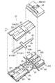
バッテリユニット21内には、空気導入口37に接続されると共に、空調装置18から送られかつ、空気導入口37からバッテリユニット21内に導入された空調空気を、各バッテリモジュール221、222に供給するためのダクト800が配設されている。ダクト800は、図3、4に示すように、上側カバー部材23の裏面に取り付けられる。ダクト800は、分配部80と、分配部80から前方に向かって延びる第1供給ダクト81及び分配部80から後方に向かって延びる第2供給ダクト82と、を備えて構成されている。
In the
分配部80は、上端が開放した上下方向に厚みの薄い矩形箱状で、車幅方向に対して、前述した2つの空気導入口37、37の間隔に相当する幅を有している。分配部80は、その上端が上側カバー部材23の第1部23aの裏面に当接することによって、この第1部23aと共に閉空間を形成する。
The
第1供給ダクト81は、分配部の前面における車幅方向内方側で、所定の間隔を空けて平行に配設された左側ダクト811と、右側ダクト812とを含んで構成されている。左側ダクト811及び右側ダクト812はそれぞれ、その基端側の部分(分配部80側の部分)が、上下方向の高さが前後方向の長さに比べて大幅に低いような扁平形状を有している。それに連続する先端側の部分は、膨出部231の高さに対応する断面三角形状になっており、左側及び右側ダクト811、812はそれぞれ、その断面形状が、途中で扁平形状から縦長形状へと切り替わっている。
The
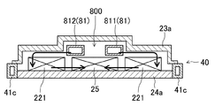
第1供給ダクト81の左側ダクト811及び右側ダクト812はそれぞれ、第1部23aの前端付近にまで延びており、この位置は、後述するバッテリモジュール221の前端に相当する。また、詳細な図示は省略するが、左側ダクト811及び右側ダクト812には、その車幅方向の外側方を向いた面に、空調空気を車幅方向の外方に向かって吹き出す吹出口が、前後方向に並んで複数個形成されている。これによって、第1収容部21a内においては、図6、7に矢印で示すように、相対的に上側に配置された第1供給ダクト81から、前後方向の所定の範囲に亘って、車幅方向の両側外方に空調空気が吹き出される。
Each of the
第2供給ダクト82は、分配部80の後面における車幅方向中央部で、後方に向かって延びて配設されている。第2供給ダクト82は、分配部80と同様に、その上面が開放されていて、上側カバー部材23の第1部23aの裏面に当接することによって閉断面を構成し、ダクトとして機能する。第2供給ダクト82もまた、第1供給ダクト81と同様に、上下方向の高さが前後方向の長さに比べて大幅に低いような扁平形状を有している。第2供給ダクト82は、車幅方向の幅が第1供給ダクト81の左側ダクト811と右側ダクト812よりも広くなっているが、第2供給ダクト82の断面積は、第1供給ダクト81における左側ダクト811と右側ダクト812との断面積の合計とほぼ等しい。
The
第2供給ダクト82の前後方向の長さは、前述した第1供給ダクト81と概ね同程度の長さに設定されており、これによって、第2供給ダクト82の後端部は、第1部23aの後端に位置する。そうして、第2供給ダクト82の後端開口には、車幅方向のダクト幅が狭くなったノズル部83が取り付けられており、このノズル部83は、図5に破線で示すように、第2収容部21bの前端部における車幅方向中央部に位置し、図6に矢印で示すように、そこから第2収容部21b内に、ノズルによって増速した空調空気を吹き出すことになる。
The length of the
バッテリユニット21の前端部には、パワーユニット71の上側に配設された不図示のインバータとバッテリユニット21とを電気的に接続するためのインバータ接続用端子31が配設されている。インバータを介してバッテリユニット21からパワーユニット71におけるモータユニット72のモータへ電力が供給される。インバータ接続用端子31は、前述の如くフレーム部材40の前部41aに設けたインバータ接続用端子支持部44(図3参照)に支持されている。
At the front end of the
図3に示すように、バッテリユニット21における複数のバッテリモジュール221、222の内、第1収容部21aに搭載されるバッテリモジュール221と、第2収容部21bに搭載されるバッテリモジュール222と、は、その形状が互いに異なる。第1収容部21aに搭載されるバッテリモジュール221は、前後方向の長さが、車幅方向の幅や上下方向の高さと比較して大幅に長く、前後方向に細長い形状を有している。この長いバッテリモジュール221は、第1収容部21aにおいて、車幅方向に間隔を空けて2つ配置されている。従って、図6、7に端的に示すように、各バッテリモジュール221は、前述した第1供給ダクト81の左側ダクト811及び右側ダクト812に対し車幅方向の両側外方位置であって、左側ダクト811及び右側ダクト812よりも下側に、それらのダクト811、812に沿うように配置されている。
As shown in FIG. 3, among the plurality of
これに対し、第2収容部21bに搭載されるバッテリモジュール222は、第1収容部21aに搭載される長いバッテリモジュール221に対して、その前後方向の長さが半分程度にされている。この短いバッテリモジュール222は、第1収容部21aよりも相対的に、車幅方向の長さが長くかつ、上下方向の高さが高く構成された第2収容部21bにおいて、車幅方向に4つ並んで配置されると共に、その各々について上下方向に3つ積層されており、第2収容部21bには、短いバッテリモジュール222が合計で12個配置されている。従って、第2収容部21bにおいては、第2供給ダクト82に対して、後方位置及び側方位置のそれぞれに、バッテリモジュール222が配設されている。
On the other hand, the
バッテリユニット21内にはまた、バッテリモジュール221、222に対する充放電制御等に関連するECUや、コンタクタ等の電気部品25が複数個、配置されており、これらの電気部品25は、第1収容部21aにおける2つのバッテリモジュール221の間の位置、第1収容部21aにおけるバッテリモジュール221よりも後方の位置、及び、第2収容部21bにおけるバッテリモジュール222の上方位置にそれぞれ配置されている。
The
バッテリユニット21内にはさらに、図3に示すように、バッテリユニット21内の空気を排出するためのファン39が配設されている。ファン39は、第1収容部21aにおけるバッテリモジュール221よりも後方の位置において、車幅方向の中央部に配置されている。従って、このファン39は、第1収容部21aに搭載されたバッテリモジュール221と、第2収容部21bに搭載されたバッテリモジュール222との間の位置であって、第1供給ダクト81及び第2供給ダクト82よりも下側の位置に配置されている。また、このファン39と、前述の空気排出口38とを接続する排気ダクト310が、バッテリユニット21内に配設されている。排気ダクト310は、ファン39から、第2収容部21bのバッテリモジュール222の間を通って後方に延び、バッテリユニット21の後端部で上向きに屈曲して配設されている。そうして、その上端開口が上側カバー部材23の第2部23bに形成された空気排出口38に接続されている。
Further, a
以上の構成により、バッテリユニット21内の空調は次のようにして行われる、すなわち、先ず空調装置18からダクト181を通じて送られた空調空気は、空気導入口37を通じてバッテリユニット21内の分配部80に導入される。空調空気は、分配部80に接続された左側ダクト811と右側ダクト812とを通じて第1収容部21aの方に流れると共に、第2供給ダクト82を通じて第2収容部21bの方に流れる。
With the above configuration, the air conditioning in the
第1収容部21aにおいては、前述したように、左側ダクト811と右側ダクト812とには、その車幅方向の外側面に複数の吹出口が形成されているため、空調空気は、各吹出口を通じて車幅方向の外方へと吹き出される。吹き出された空調空気は、図6、7に矢印で示すように、左側ダクト811及び右側ダクト812に対し車幅方向の両側外方の下側に配置されたバッテリモジュール221に供給される。そうして、第1収容部21aに収容されている2つのバッテリモジュール221のそれぞれについて、温度調整が行われる。
In the first
その後、空調空気は、バッテリユニット21内の底面に沿って、車幅方向の外方から内方へと流れるようになり、2つのバッテリモジュール221の間に配設されている電気部品25に対する温度調整が行われる。
Thereafter, the conditioned air flows from the outside in the vehicle width direction to the inside along the bottom surface in the
そうして、空調空気は、バッテリモジュール221及び電気部品25の温度調整を行った後に、車幅方向の中央部を車体後方側へと流れるようになり、バッテリモジュール221の後方に配置されたファン39に吸い込まれる。
Then, after adjusting the temperature of the
これに対し、第2部23b内では、第2供給ダクト82を通じて後方に流れる空調空気が、その前側部分における車幅方向の中央部に位置する吹出口から、後方に向かって吹き出される。これによって、空調空気は、前後方向についての長さが比較的短い矩形箱状の第2収容部23b内で、前後方向の後方、車幅方向の両側外方、及び、上下方向のそれぞれに拡がるように流れて、そこに収容されている各バッテリモジュール222の温度調整を行う。
On the other hand, in the
その後、空調空気は、バッテリユニット21内の底面に沿って、車幅方向の外方から内方に向かって流れると共に、前後方向の後方から前方に向かって流れるように循環し、最終的にはファン39に至り、そのファン39に吸い込まれる。
Thereafter, the conditioned air circulates along the bottom surface in the
そうして、第1収容部21a及び第2収容部21bのそれぞれから戻ってきた空調空気は、ファン39の作動に伴い、排気ダクト310を通じて流れて空気排出口38からバッテリユニット21の外へと排出される。
Then, the conditioned air that has returned from each of the
このように、このバッテリユニット21は、その内部に複数のバッテリモジュール221、222を、その前側と後側とに分散して配置している一方で、車室用空調装置18からの空調空気をバッテリユニット21内に導入するための空気導入口37を、バッテリユニット21の中間部、より正確には、第1収容部21aのバッテリモジュール221と、第2収容部21bのバッテリモジュール222との間付近に配置しており、そこから、第1供給ダクト81及び第2供給ダクト82を通じて、第1収容部21aのバッテリモジュール221と、第2収容部21bのバッテリモジュール222とのそれぞれに、空調空気を分配供給するようにしている。
As described above, the
この構成により、前側のバッテリモジュール221と、後側のバッテリモジュール222とのそれぞれについて、空気導入口37から導入した空調空気を直接的に供給することが可能になるため、前側のバッテリモジュール221に供給する空調空気の温度と、後側のバッテリモジュール222に供給する空調空気の温度とを実質的に同じ温度にする。その結果、前側のバッテリモジュール221と後側のバッテリモジュール222との温度調整を均一化することが可能になる。このことは、バッテリユニット21内の複数のバッテリモジュール221、222間の温度差を小さくする上で有利である。
With this configuration, the conditioned air introduced from the
ここで、第1供給ダクト81及び第2供給ダクト82をそれぞれ、バッテリユニット21内で車幅方向中央部に配設しているため、これら第1及び第2供給ダクト81、82の長さを最短にしながらも、第1収容部21a及び第2収容部21bのそれぞれに収容されたバッテリモジュール221、222に、空調空気を効率的に分配供給することが可能になる。このことは、バッテリユニット21の軽量化に有利である。
Here, since the
また、そのように車幅方向中央部において、第1収容部21a内を前後方向に延びるように配設された第1供給ダクト81(左側ダクト811及び右側ダクト812)に対して、バッテリモジュール221は、左側ダクト811及び右側ダクト812の下方位置であって、車幅方向の両側外方において、その左側ダクト811及び右側ダクト812に沿うように配設されている一方で、それらの左側ダクト811及び右側ダクト812からは車幅方向の両側外方に向かって空調空気が吹き出される。このため、バッテリモジュール221に対して、効率的に空調空気を供給することが可能である。
In addition, the
また、左側ダクト811及び右側ダクト812から吹き出された空調空気は、第1収容部21a内を循環するように流れるから、空調空気とバッテリモジュール221との熱交換を効率的に行って、バッテリモジュール221の温度調整を効率的に行うことを可能になると共に、その後に、電気部品25の温度調整をも効率的に行うことが可能になる。特に、バッテリモジュール221と電気部品25とを比較したときには、バッテリモジュール221の方が温度調整に対する要求が高いため、左側ダクト811及び右側ダクト812からの空調空気を、先にバッテリモジュール221に供給し、その後に電気部品25に供給することは、バッテリモジュール221及び電気部品25のそれぞれを、適切に温度調整することを可能にする。
Moreover, since the conditioned air blown out from the
これに対して第2収容部21bにおいては、その前端部でかつ車幅方向の中央部に吹出口を配置し、そこから後方に向かって空調空気を吹き出すことで、第2収容部21b内で空調空気を効率的に循環させて、多数のバッテリモジュール222の温度調整を効率的に行うことが可能である。
On the other hand, in the 2nd
さらに、第1収容部21aのバッテリモジュール221と、第2収容部21bのバッテリモジュール222との間の車幅方向の中央部であって、第1供給ダクト81及び第2供給ダクト82の下側に、排気用のファン39を配置することによって、バッテリユニット21内で、前後方向、車幅方向、及び上下方向のそれぞれについて、空調空気を効率良く循環することが可能になり、バッテリモジュール221、222の温度調整を、より均一にかつ効果的に行うことが可能になる。
Furthermore, it is a center part of the vehicle width direction between the
ここで、第1供給ダクト81は、左側ダクト811と右側ダクト812との2本のダクトに分離し、かつ、吹出口を双方に複数個、設けているのに対し、第2供給ダクト82は、1本のダクトで、比較的大きい吹出口を一つだけ設けている。そのため、第1供給ダクト81側の流路抵抗の方が、第2供給ダクト82側の流路抵抗よりも大きくなり、分配部80から流れる空調空気の流量は、第2供給ダクト82側の方が相対的に大きくなる。このことは、第1収容部21aのバッテリモジュール221の数が少ない一方で、第2収容部21bのバッテリモジュール222は、数が多く、しかも密に配置されていることに対応し、第2収容部21bの多数のバッテリモジュール222を、より効率良く温度調整する上で有利になる。その結果、第1収容部21aのバッテリモジュール221と、第2収容部21bのバッテリモジュール222との温度差は小さくなる。このことは、バッテリ性能の向上に有利になる。
Here, the
また、第1収容部21a内に配置される第1供給ダクト81(特に、その基端側の部分)及び第2供給ダクト82の断面をそれぞれ、上下の高さよりも左右の幅が広い扁平な形状にすることで、車室フロアパネル1の下側の、上下の高さについて十分なスペースを確保することが困難なバッテリユニット21内に、省スペース化を図りつつも、必要なダクト断面積を確保して十分な空調空気の流量を得ることが可能になる。
Further, the first supply duct 81 (particularly, the base end portion) and the
さらに、第1供給ダクト81と第2供給ダクト82とは、略等しいダクト長を有していることで、第1収容部21a側への空調空気の供給量と、第2収容部21b側への空調空気の供給量とをそれぞれ十分に確保して、第1収容部21a及び第2収容部21bの双方に収容されたバッテリモジュール221、222の温度調整を適切に行うことを可能にする。
Furthermore, the
また、バッテリユニット21に導入する空気は、車室用空調装置18の空調空気であるため、バッテリモジュール221、222の温度調整を効率的に行うことが可能である。この構成において、このバッテリユニット21の空気導入口37は、前後方向の中間部に形成していて、ダッシュパネル11近傍の空調装置18から離れているため、ダクトが必要になるものの、前記の構成では、既存のダクト181、181を利用してバッテリユニット21に空調空気を導入(供給)するため、新たなダクトが不要であるという利点がある。
Moreover, since the air introduced into the
尚、分配部80から前方の第1収容部21aに向かって延びる第1供給ダクトと、後方の第2収容部21bに向かって延びる第2供給ダクトとの構成は前記の構成には限定されず、第1収容部21a内のバッテリモジュールの配置構成(例えばバッテリモジュールの形状、数等)と、第2収容部21b内のバッテリモジュールの配置構成とに応じて、適宜設定すればよい。
In addition, the structure of the 1st supply duct extended toward the front
本発明は、車室フロアの下側にバッテリユニットが搭載された、例えば電気自動車等の電動車両のバッテリユニットの空調構造に有用である。 The present invention is useful for an air conditioning structure of a battery unit of an electric vehicle such as an electric vehicle in which the battery unit is mounted on the lower side of the passenger compartment floor.
1 車室フロアパネル(車室フロア)
1a フロントフロア部
1b リヤフロア部
11 ダッシュパネル
18 車室用空調装置
21 バッテリユニット
21a 第1収容部
21b 第2収容部
221 バッテリモジュール
222 バッテリモジュール
25 電気部品
37 空気導入口(導入口)
39 ファン
310 排気ダクト
80 分配部
81 第1供給ダクト
811 右側ダクト
812 左側ダクト
82 第2供給ダクト
800 ダクト
1 Car floor panel (car floor)
DESCRIPTION OF
39
Claims (9)
前記車室フロアは、フロントフロア部と、当該フロントフロア部に対し車体前後方向の後側に配設されたリヤフロア部と、を含み、
前記バッテリユニットは、前記フロントフロア部の下側に配設されかつ、前記バッテリモジュールを内部に収容する第1収容部と、前記リヤフロア部の下側に配設されて、その内部が前記第1収容部内に連通していると共に、前記バッテリモジュールを内部に収容する第2収容部と、を含み、
前記バッテリユニットにおける車体前後方向の中間部には、車室用空調装置からの空調空気をユニット内部に導入する導入口と、導入された空調空気を前記第1収容部の方と前記第2収容部の方とに分配する分配部と、が設けられ、
前記分配部には、前記バッテリユニットの車幅方向中央部において前記分配部から前方に向かって延びることにより、前記導入された空調空気を前記第1収容部のバッテリモジュールに供給する第1供給ダクトと、前記バッテリユニットの車幅方向中央部において前記分配部から後方に向かって延びることにより、前記導入された空調空気を前記第2収容部のバッテリモジュールに供給する第2供給ダクトとが、それぞれ接続されている車両用バッテリユニットの空調構造。 An air conditioning structure for a vehicle battery unit in which a battery unit that houses a plurality of battery modules and electrical components is mounted below the passenger compartment floor,
The vehicle compartment floor includes a front floor portion, and a rear floor portion disposed on the rear side in the vehicle longitudinal direction with respect to the front floor portion,
The battery unit is disposed on the lower side of the front floor portion, and is disposed on the lower side of the rear floor portion, and a first housing portion for housing the battery module therein. A second housing portion that communicates within the housing portion and houses the battery module therein;
In the middle part of the battery unit in the front-rear direction of the vehicle body, an inlet for introducing conditioned air from the cabin air conditioner into the unit, and the introduced conditioned air toward the first housing part and the second housing A distribution unit that distributes to the part,
The distribution unit includes a first supply duct that supplies the introduced conditioned air to the battery module of the first housing unit by extending forward from the distribution unit at a vehicle width direction central portion of the battery unit. And a second supply duct for supplying the introduced conditioned air to the battery module of the second housing part by extending rearward from the distribution part at the vehicle width direction central part of the battery unit, respectively. The air conditioning structure of the connected vehicle battery unit.
前記第1供給ダクト及び前記第2供給ダクトはそれぞれ、前記バッテリユニット内における相対的に上側の高さ位置に配設され、
前記バッテリユニットにおける車体前後方向の中間部の車幅方向中央部であって、前記第1及び第2供給ダクトよりも下側の高さ位置には、当該バッテリユニット内の空気を排気するためのファンが配設され、
前記ファンには、前記第2収容部の後方へと延びる排気ダクトが接続されている車両用バッテリユニットの空調構造。 In the air conditioning structure of the vehicle battery unit according to claim 1,
Each of the first supply duct and the second supply duct is disposed at a relatively upper height position in the battery unit,
A middle portion of the battery unit in the longitudinal direction of the vehicle body in the vehicle width direction, and at a height position below the first and second supply ducts for exhausting air in the battery unit. A fan is arranged,
An air conditioning structure for a vehicle battery unit, wherein an exhaust duct extending to the rear of the second housing portion is connected to the fan.
前記第1収容部のバッテリモジュールは、車幅方向中央部において車体前後方向に延びて配置された前記第1供給ダクトに対し車幅方向の両側外方位置に配置され、
前記第1収容部には、前記バッテリモジュールに対し車幅方向の内方位置であって、当該バッテリモジュールと略同じ高さ位置に、前記電気部品が配置され、
前記第1供給ダクトは、前記バッテリモジュール及び電気部品よりも上側の高さ位置に配設されかつ、車幅方向の内方側から両側の外方に向かって前記空調空気を吹き出すように構成されている車両用バッテリユニットの空調構造。 In the air conditioning structure of the vehicle battery unit according to claim 1 or 2,
The battery module of the first housing portion is disposed at both lateral outer positions in the vehicle width direction with respect to the first supply duct disposed to extend in the vehicle body front-rear direction in the vehicle width direction center portion.
In the first housing portion, the electrical component is disposed at an inner position in the vehicle width direction with respect to the battery module and at substantially the same height position as the battery module,
The first supply duct is disposed at a height position above the battery module and the electrical component, and is configured to blow out the conditioned air from the inner side in the vehicle width direction toward the outer side on both sides. The air conditioning structure of the vehicle battery unit.
前記第2収容部のバッテリモジュールは、前記第2供給ダクトに対して車幅方向の両側位置、車体前後方向の後側位置、又は、前記車幅方向の両側位置と車体前後方向の後側位置との双方に配置されている車両用バッテリユニットの空調構造。 In the air-conditioning structure of the vehicle battery unit according to any one of claims 1 to 3,
The battery module of the second housing portion may be positioned on both sides in the vehicle width direction with respect to the second supply duct, on the rear side in the vehicle longitudinal direction, or on both sides in the vehicle width direction and on the rear side in the vehicle longitudinal direction. The air conditioning structure of the vehicle battery unit disposed on both sides.
前記第1供給ダクト及び第2供給ダクトの断面はそれぞれ、上下の高さよりも左右の幅が広い扁平な形状を有している車両用バッテリユニットの空調構造。 In the air conditioning structure of the vehicle battery unit according to any one of claims 1 to 4,
Each of the cross sections of the first supply duct and the second supply duct is an air conditioning structure for a vehicle battery unit having a flat shape in which the left and right widths are wider than the vertical height.
前記第1供給ダクトと前記第2供給ダクトとは、略等しいダクト長を有している車両用バッテリユニットの空調構造。 In the air conditioning structure of the vehicle battery unit according to any one of claims 1 to 5,
The air supply structure for a vehicle battery unit, wherein the first supply duct and the second supply duct have substantially equal duct lengths.
前記第1供給ダクトと前記第2供給ダクトとは、略等しい断面積を有している車両用バッテリユニットの空調構造。 In the air conditioning structure of the vehicle battery unit according to any one of claims 1 to 6,
The air supply structure for a vehicle battery unit, wherein the first supply duct and the second supply duct have substantially equal cross-sectional areas.
前記第1供給ダクトは、互いに平行となるように車幅方向に並んで配置された右側ダクトと左側ダクトとを含んで構成されている車両用バッテリユニットの空調構造。 In the air conditioning structure of the vehicle battery unit according to any one of claims 1 to 7,
The first supply duct is an air conditioning structure for a vehicle battery unit configured to include a right duct and a left duct arranged in parallel in the vehicle width direction so as to be parallel to each other.
前記バッテリユニットの導入口は、ダッシュパネル近傍に配設された車室用空調装置から、後席乗員の足下に配設された空気吹出口まで延びるダクトに対し、接続されている車両用バッテリユニットの空調構造。 In the air conditioning structure of the vehicle battery unit according to any one of claims 1 to 8,
The battery unit introduction port is connected to a vehicle battery unit connected to a duct extending from a passenger compartment air conditioner disposed in the vicinity of the dash panel to an air outlet disposed under the foot of the rear seat occupant. Air conditioning structure.
Priority Applications (1)
| Application Number | Priority Date | Filing Date | Title |
|---|---|---|---|
| JP2011057443A JP5482697B2 (en) | 2011-03-16 | 2011-03-16 | Air conditioning structure for vehicle battery unit |
Applications Claiming Priority (1)
| Application Number | Priority Date | Filing Date | Title |
|---|---|---|---|
| JP2011057443A JP5482697B2 (en) | 2011-03-16 | 2011-03-16 | Air conditioning structure for vehicle battery unit |
Publications (2)
| Publication Number | Publication Date |
|---|---|
| JP2012192809A true JP2012192809A (en) | 2012-10-11 |
| JP5482697B2 JP5482697B2 (en) | 2014-05-07 |
Family
ID=47085147
Family Applications (1)
| Application Number | Title | Priority Date | Filing Date |
|---|---|---|---|
| JP2011057443A Expired - Fee Related JP5482697B2 (en) | 2011-03-16 | 2011-03-16 | Air conditioning structure for vehicle battery unit |
Country Status (1)
| Country | Link |
|---|---|
| JP (1) | JP5482697B2 (en) |
Cited By (8)
| Publication number | Priority date | Publication date | Assignee | Title |
|---|---|---|---|---|
| JP2013244861A (en) * | 2012-05-28 | 2013-12-09 | Mazda Motor Corp | Air conditioning structure of vehicular battery unit |
| JP2013244860A (en) * | 2012-05-28 | 2013-12-09 | Mazda Motor Corp | Air conditioning structure of vehicle battery unit |
| WO2014073150A1 (en) * | 2012-11-07 | 2014-05-15 | 株式会社デンソー | Cooling device |
| US20160301120A1 (en) * | 2015-04-08 | 2016-10-13 | Honda Motor Co., Ltd. | Cooling structure of battery and battery unit |
| JP2016199106A (en) * | 2015-04-08 | 2016-12-01 | 本田技研工業株式会社 | Battery cooling structure |
| JP2016199105A (en) * | 2015-04-08 | 2016-12-01 | 本田技研工業株式会社 | Battery unit |
| JP2021116047A (en) * | 2020-01-29 | 2021-08-10 | 株式会社デンソー | Seat air-conditioning device |
| CN115384631A (en) * | 2022-08-30 | 2022-11-25 | 岚图汽车科技有限公司 | Battery pack mounting assembly, automobile and method |
Citations (5)
| Publication number | Priority date | Publication date | Assignee | Title |
|---|---|---|---|---|
| JP2000301954A (en) * | 1999-04-16 | 2000-10-31 | Shin Kobe Electric Mach Co Ltd | Battery for vehicle |
| JP2001105894A (en) * | 1999-10-14 | 2001-04-17 | Daihatsu Motor Co Ltd | Battery cooling device for electric vehicle |
| JP2009087646A (en) * | 2007-09-28 | 2009-04-23 | Mitsubishi Motors Corp | Battery unit for electric vehicle |
| JP2011079411A (en) * | 2009-10-07 | 2011-04-21 | Suzuki Motor Corp | Battery cooling structure of vehicle |
| JP2011134615A (en) * | 2009-12-24 | 2011-07-07 | Mitsubishi Motors Corp | Cooling structure of battery pack |
-
2011
- 2011-03-16 JP JP2011057443A patent/JP5482697B2/en not_active Expired - Fee Related
Patent Citations (5)
| Publication number | Priority date | Publication date | Assignee | Title |
|---|---|---|---|---|
| JP2000301954A (en) * | 1999-04-16 | 2000-10-31 | Shin Kobe Electric Mach Co Ltd | Battery for vehicle |
| JP2001105894A (en) * | 1999-10-14 | 2001-04-17 | Daihatsu Motor Co Ltd | Battery cooling device for electric vehicle |
| JP2009087646A (en) * | 2007-09-28 | 2009-04-23 | Mitsubishi Motors Corp | Battery unit for electric vehicle |
| JP2011079411A (en) * | 2009-10-07 | 2011-04-21 | Suzuki Motor Corp | Battery cooling structure of vehicle |
| JP2011134615A (en) * | 2009-12-24 | 2011-07-07 | Mitsubishi Motors Corp | Cooling structure of battery pack |
Cited By (12)
| Publication number | Priority date | Publication date | Assignee | Title |
|---|---|---|---|---|
| JP2013244861A (en) * | 2012-05-28 | 2013-12-09 | Mazda Motor Corp | Air conditioning structure of vehicular battery unit |
| JP2013244860A (en) * | 2012-05-28 | 2013-12-09 | Mazda Motor Corp | Air conditioning structure of vehicle battery unit |
| WO2014073150A1 (en) * | 2012-11-07 | 2014-05-15 | 株式会社デンソー | Cooling device |
| JP2014095484A (en) * | 2012-11-07 | 2014-05-22 | Denso Corp | Cooling apparatus |
| US20160301120A1 (en) * | 2015-04-08 | 2016-10-13 | Honda Motor Co., Ltd. | Cooling structure of battery and battery unit |
| CN106058361A (en) * | 2015-04-08 | 2016-10-26 | 本田技研工业株式会社 | Cooling structure of battery and battery unit |
| JP2016199106A (en) * | 2015-04-08 | 2016-12-01 | 本田技研工業株式会社 | Battery cooling structure |
| JP2016199105A (en) * | 2015-04-08 | 2016-12-01 | 本田技研工業株式会社 | Battery unit |
| US10418675B2 (en) | 2015-04-08 | 2019-09-17 | Honda Motor Co., Ltd. | Cooling structure of battery and battery unit |
| JP2021116047A (en) * | 2020-01-29 | 2021-08-10 | 株式会社デンソー | Seat air-conditioning device |
| JP7264074B2 (en) | 2020-01-29 | 2023-04-25 | 株式会社デンソー | seat air conditioner |
| CN115384631A (en) * | 2022-08-30 | 2022-11-25 | 岚图汽车科技有限公司 | Battery pack mounting assembly, automobile and method |
Also Published As
| Publication number | Publication date |
|---|---|
| JP5482697B2 (en) | 2014-05-07 |
Similar Documents
| Publication | Publication Date | Title |
|---|---|---|
| JP5482697B2 (en) | Air conditioning structure for vehicle battery unit | |
| JP5277362B1 (en) | In-vehicle structure of battery pack | |
| JP5825694B2 (en) | In-vehicle structure of battery pack | |
| US20180099552A1 (en) | Rear-drive electric vehicle | |
| JP4363350B2 (en) | Secondary battery cooling structure | |
| JP2006335243A (en) | Power supply device for vehicle | |
| JP5924130B2 (en) | Air conditioning structure for vehicle battery unit | |
| JP4701916B2 (en) | Car battery mounting structure | |
| US20150274013A1 (en) | Electric Vehicle | |
| JP6343686B2 (en) | Vehicle power supply | |
| US9950601B2 (en) | Vehicle with high voltage equipment arranged behind seat | |
| JP4756333B2 (en) | Car battery mounting structure | |
| JP4105033B2 (en) | In-vehicle structure of high-voltage components | |
| JP7280549B2 (en) | vehicle battery cooler | |
| CN110893758A (en) | Vehicle with a steering wheel | |
| US20050011640A1 (en) | Air conditioner for vehicle | |
| JP2006339048A (en) | Battery-cooling structure | |
| JP2007050801A (en) | Battery mounting structure for automobile | |
| WO2022224947A1 (en) | Cooling device | |
| US20230094047A1 (en) | Vehicle-body structure with controller | |
| JP5962163B2 (en) | Air conditioning structure for vehicle battery unit | |
| JP2022154900A (en) | electric vehicle | |
| JP5924129B2 (en) | Air conditioning structure for vehicle battery unit | |
| JP2019156003A (en) | Vehicle lower part structure | |
| EP4163188A1 (en) | Vehicle-body structure |
Legal Events
| Date | Code | Title | Description |
|---|---|---|---|
| A621 | Written request for application examination |
Free format text: JAPANESE INTERMEDIATE CODE: A621 Effective date: 20130313 |
|
| RD02 | Notification of acceptance of power of attorney |
Free format text: JAPANESE INTERMEDIATE CODE: A7422 Effective date: 20130401 |
|
| TRDD | Decision of grant or rejection written | ||
| A01 | Written decision to grant a patent or to grant a registration (utility model) |
Free format text: JAPANESE INTERMEDIATE CODE: A01 Effective date: 20140121 |
|
| A977 | Report on retrieval |
Free format text: JAPANESE INTERMEDIATE CODE: A971007 Effective date: 20140123 |
|
| A61 | First payment of annual fees (during grant procedure) |
Free format text: JAPANESE INTERMEDIATE CODE: A61 Effective date: 20140203 |
|
| R150 | Certificate of patent or registration of utility model |
Ref document number: 5482697 Country of ref document: JP Free format text: JAPANESE INTERMEDIATE CODE: R150 |
|
| LAPS | Cancellation because of no payment of annual fees |