JP2012190838A - Terminal box - Google Patents
Terminal box Download PDFInfo
- Publication number
- JP2012190838A JP2012190838A JP2011050526A JP2011050526A JP2012190838A JP 2012190838 A JP2012190838 A JP 2012190838A JP 2011050526 A JP2011050526 A JP 2011050526A JP 2011050526 A JP2011050526 A JP 2011050526A JP 2012190838 A JP2012190838 A JP 2012190838A
- Authority
- JP
- Japan
- Prior art keywords
- cable
- semi
- cylindrical portion
- terminal
- terminal box
- Prior art date
- Legal status (The legal status is an assumption and is not a legal conclusion. Google has not performed a legal analysis and makes no representation as to the accuracy of the status listed.)
- Granted
Links
Images


Classifications
-
- Y—GENERAL TAGGING OF NEW TECHNOLOGICAL DEVELOPMENTS; GENERAL TAGGING OF CROSS-SECTIONAL TECHNOLOGIES SPANNING OVER SEVERAL SECTIONS OF THE IPC; TECHNICAL SUBJECTS COVERED BY FORMER USPC CROSS-REFERENCE ART COLLECTIONS [XRACs] AND DIGESTS
- Y02—TECHNOLOGIES OR APPLICATIONS FOR MITIGATION OR ADAPTATION AGAINST CLIMATE CHANGE
- Y02E—REDUCTION OF GREENHOUSE GAS [GHG] EMISSIONS, RELATED TO ENERGY GENERATION, TRANSMISSION OR DISTRIBUTION
- Y02E10/00—Energy generation through renewable energy sources
- Y02E10/50—Photovoltaic [PV] energy
Abstract
Description
本発明は、端子ボックスに関し、特に、端子ボックスから外部に引き出されるケーブルのクランプ構造を有する端子ボックスに関するものである。 The present invention relates to a terminal box, and more particularly to a terminal box having a clamp structure for a cable drawn out from the terminal box.
従来、装置間の電気的接続を行うために種々の形態の端子ボックスが用いられている。例えば太陽光発電システムの太陽電池パネルでは複数枚の太陽電池モジュールを縦横に並べ、各太陽電池モジュールにそれぞれ外部出力用ケーブルが接続される端子ボックスが取り付けられているものがある(例えば特許文献1参照)。 Conventionally, various types of terminal boxes are used for electrical connection between devices. For example, in a solar battery panel of a solar power generation system, there are ones in which a plurality of solar battery modules are arranged vertically and horizontally, and a terminal box to which an external output cable is connected is attached to each solar battery module (for example, Patent Document 1). reference).
上記したような太陽電池モジュール用端子ボックスでは、合成樹脂製のケースの中に、太陽電池モジュールの正負の電極に接続されかつ外部出力用ケーブルが接続される2個の端子が設けられているものがある。そのような端子ボックスでは、太陽電池モジュールが屋外に設置されることから、上記端子や各種電気素子の絶縁性の確保のために、端子ボックスには防水性が要求される。端子ボックスの防水としては、合成樹脂材をケース内に充填するポッティングを行うと良いが、そのポッティング液の漏洩を防止する必要がある。特に、端子ボックスには上記した外部接続用ケーブルが外部に引き出されるように接続されており、その引き出し部分からのポッティング液が漏洩し易いという問題がある。 In the terminal box for a solar cell module as described above, two terminals that are connected to the positive and negative electrodes of the solar cell module and to which an external output cable is connected are provided in a synthetic resin case. There is. In such a terminal box, since the solar cell module is installed outdoors, the terminal box is required to be waterproof in order to ensure insulation of the terminals and various electric elements. For waterproofing of the terminal box, potting in which a synthetic resin material is filled in the case is preferably performed, but it is necessary to prevent leakage of the potting liquid. In particular, the terminal box is connected so that the above-described external connection cable is drawn out, and there is a problem that potting liquid from the drawn-out portion is likely to leak.
また、ケーブルの外部引き出し部分のクランプ構造において、端子ボックスの端子を受容する箱状の本体と、本体に取り付けられるケーブルクランプとを有し、ケーブルを外囲する半円筒状の凹設部をそれぞれ設け、ケーブルクランプを本体に取り付けた状態で両凹設部によりケーブルを外囲して保持するようにしたものがある。一方、ケーブルが引き出されている端子ボックスでは、ケーブルが固定されるまでは何等かの外力がケーブルに作用して、ケーブルに引き抜き力が作用する場合がある。したがって、端子ボックスには、上記ポッティング液の漏洩を防止すると共にケーブルに加わる引き抜き力に対する高い耐引き抜き力が要求される。 In addition, in the clamp structure of the external lead portion of the cable, each has a box-shaped main body that receives the terminal of the terminal box and a cable clamp attached to the main body, and each of the semi-cylindrical concave portions that surround the cable. There are some which are provided with a cable clamp attached to the main body so that the cable is surrounded and held by both concave portions. On the other hand, in the terminal box from which the cable is drawn, some external force may act on the cable until the cable is fixed, and a pulling force may act on the cable. Therefore, the terminal box is required to have a high pull-out resistance against the pull-out force applied to the cable while preventing leakage of the potting liquid.
このような課題を解決して、端子ボックスにおけるポッティング液の漏洩の防止及び外部接続ケーブルの耐引き抜き力を向上するために、本発明に於いては、外部接続用ケーブルと結合された端子を受容しかつ固定するための端子ボックスであって、前記端子ボックスが、前記端子を受容する箱状の本体と、前記本体から外方に延出される前記ケーブルを通すべく前記本体に設けられた半円筒凹設状の第1半円筒部と、前記第1半円筒部との間に前記ケーブルを挟持するように形成された半円筒凹設状の第2半円筒部を有しかつ前記本体に取り付けられたケーブルクランプとを有し、前記第1半円筒部と前記第2半円筒部との各内周面に、前記本体に前記ケーブルクランプが取り付けられた状態で前記ケーブルの軸線方向に異なる位置で互い違いに前記ケーブルの外周面を径方向に押圧するための複数の円弧状突条が配設されているものとした。 In order to solve such problems and prevent the leakage of potting liquid in the terminal box and improve the pull-out force of the external connection cable, the present invention accepts a terminal combined with the external connection cable. And a terminal box for fixing, wherein the terminal box is provided in the main body so as to pass a box-shaped main body for receiving the terminal and the cable extending outward from the main body. A concave semi-cylindrical second semi-cylindrical portion formed so as to sandwich the cable between the concave semi-cylindrical first semi-cylindrical portion and the first semi-cylindrical portion, and attached to the main body Cable clamps, and different positions in the axial direction of the cable in a state where the cable clamps are attached to the main body on the inner peripheral surfaces of the first semi-cylindrical part and the second semi-cylindrical part. In each other A plurality of arcuate projections for pressing the outer peripheral surface of the cable radially There is assumed to be provided.
これによれば、ケーブルを外囲する両半円筒部にそれぞれ設けた複数の円弧状突条がケーブルの軸線方向に異なる位置に設けられ、かつケーブルの外周面を互い違いに径方向に押圧することから、ケーブルが蛇行状態でクランプされることになり、ケーブルの耐引き抜き力が向上する。 According to this, the plurality of arc-shaped ridges respectively provided on both semi-cylindrical portions surrounding the cable are provided at different positions in the axial direction of the cable and alternately press the outer peripheral surface of the cable in the radial direction. Therefore, the cable is clamped in a meandering state, and the pull-out resistance of the cable is improved.
特に、前記複数の円弧状突条の少なくとも1つの突出方向端部の前記ケーブルの引き抜き方向とは相反する側に、直角を含む鋭角となる角部が形成されていると良い。これによれば、ケーブルに引き抜き力が加わった場合に、ケーブルの外周面に角部が食い込むようになるため、ケーブルの耐引き抜き力がより一層向上する。 In particular, it is preferable that an acute angle corner including a right angle is formed on the side opposite to the cable drawing direction of at least one protruding direction end of the plurality of arc-shaped protrusions. According to this, when a pulling force is applied to the cable, the corner portion bites into the outer peripheral surface of the cable, so that the pulling resistance of the cable is further improved.
また、前記複数の円弧状突条が前記第1半円筒部と前記第2半円筒部との少なくとも一方の内周面に2つ以上設けられ、前記2つ以上の円弧状突条の少なくとも1つの隣り合う間に前記両半円筒部の軸線方向に沿うように延在する軸線方向突条が設けられていると良い。これによれば、軸線方向突条がケーブルの周方向変位に対して抵抗となり、ケーブルねじり変位に対する耐久力を高めることができる。また、円弧状突条が互い違いに配設されていることから、軸線方向突条に対向する位置の円弧状突条により押圧されるため、軸線方向突条のみを設けた場合より強固にねじり防止が実現される。 Two or more of the plurality of arc-shaped ridges are provided on at least one inner peripheral surface of the first semi-cylindrical portion and the second semi-cylindrical portion, and at least one of the two or more arc-shaped ridges is provided. An axial ridge extending along the axial direction of the two semi-cylindrical portions may be provided between two adjacent cylinders. According to this, an axial protrusion becomes resistance with respect to the circumferential direction displacement of a cable, and can improve durability with respect to cable torsional displacement. In addition, since the arc-shaped ridges are alternately arranged, the arc-shaped ridges are pressed by the arc-shaped ridges at positions opposite to the axial ridges, so that the twist prevention is stronger than when only the axial ridges are provided. Is realized.
あるいは、外部接続用ケーブルと結合された端子を受容しかつ固定するための端子ボックスであって、前記端子ボックスが、前記端子を受容する箱状の本体と、前記本体から外方に延出される前記ケーブルを通すべく前記本体に設けられた半円筒凹設状の第1半円筒部と、前記第1半円筒部との間に前記ケーブルを挟持するように形成された半円筒凹設状の第2半円筒部を有しかつ前記本体に取り付けられたケーブルクランプとを有し、前記第1半円筒部と前記第2半円筒部との各内周面に、前記本体に前記ケーブルクランプが取り付けられた状態で前記ケーブルの外周面に全周に亘って食い込むようにそれぞれ突設された各円弧状突条が互いに周方向に連続するように設けられ、前記各円弧状突条の互いに対向する各周方向端面が前記ケーブルの外周面に向けて拡開するように形成されているものとした。 Alternatively, a terminal box for receiving and fixing a terminal combined with an external connection cable, the terminal box extending outward from the main body and a box-shaped main body for receiving the terminal A semi-cylindrical concave shape formed so as to sandwich the cable between a first semi-cylindrical portion provided in the main body to pass the cable and a semi-cylindrical concave shape provided in the main body. A cable clamp having a second semi-cylindrical portion and attached to the main body, and the cable clamp on the main body on each inner peripheral surface of the first semi-cylindrical portion and the second semi-cylindrical portion. Each of the arc-shaped ridges protruding so as to bite into the outer peripheral surface of the cable over the entire circumference in the attached state is provided so as to be continuous in the circumferential direction, and the arc-shaped ridges are opposed to each other. Each circumferential end face to be It was assumed to be formed so as to be widened toward the outer peripheral surface of the Le.
これによれば、ポッティング液漏洩を防止するべくケーブルの外周面を全周に亘って食い込むように設けられた各円弧状突条によりケーブルを径方向に両側から挟持すると、各円弧状突条の互いに対向する各周方向端面間にケーブルの被覆を噛み込む虞があるが、各周方向端面が拡開していることにより、被覆の余肉が拡開部分に逃げることができるため、噛み込みによるケーブルクランプと本体との合わせ面の密着性が損なわれることを好適に防止し得る。 According to this, when the cable is clamped from both sides in the radial direction by the respective arc-shaped ridges provided so as to bite the outer peripheral surface of the cable over the entire circumference in order to prevent the leakage of potting liquid, There is a risk that the cable coating will be caught between the circumferential end faces facing each other, but because the circumferential end faces are widened, the surplus thickness of the coating can escape to the expanded portion, so that It is possible to suitably prevent the adhesion of the mating surface between the cable clamp and the main body from being impaired.
このように本発明によれば、端子ボックスの本体に設けた半円筒部と、本体に取り付けられるケーブルクランプに設けた半円筒部とによりケーブルを外囲すると共に、それら両半円筒部にそれぞれケーブルの軸線方向に異なる位置に複数の円弧状突条を設けて、ケーブルの外周面を互い違いに径方向に押圧することにより、ケーブルが蛇行状態でクランプされることになり、ケーブルの耐引き抜き力を向上することができる。 As described above, according to the present invention, the cable is surrounded by the semi-cylindrical portion provided in the main body of the terminal box and the semi-cylindrical portion provided in the cable clamp attached to the main body, and the cables are respectively connected to both the semi-cylindrical portions. By providing a plurality of arc-shaped ridges at different positions in the axial direction of the cable and pressing the outer peripheral surface of the cable alternately in the radial direction, the cable is clamped in a meandering state, and the cable's pull-out resistance is increased. Can be improved.
以下、本発明の実施の形態を、図面を参照しながら説明する。図1は本発明に基づく端子ボックス1の組み立て分解斜視図であり、図2は、本発明が適用された太陽光発電システムにおける太陽電池モジュール2と端子ボックス1との接続を示す組み立て分解斜視図である。
Hereinafter, embodiments of the present invention will be described with reference to the drawings. FIG. 1 is an exploded exploded perspective view of a
図1及び図2に示されるように、端子ボックス1は、合成樹脂材の成形品からなり、図における上方に開口する扁平な矩形箱形のボディ3と、ボディ3の図における上面を覆うための矩形平板状のカバー4と、ボディ3の内部に固定される端子ボックス用端子(以下端子と称す)5が結合されている外部接続用ケーブル6をボディ3との間で固定するための各ケーブルクランプ7とにより構成されている。
As shown in FIGS. 1 and 2, the
本図示例では、4つの端子5がボディ3内に配設されるようになっており、各端子5の隣り合うものの間には本体が円柱型の電気素子としてのバイパスダイオード8が接続される。円柱型の場合には、図に示されるように軸線方向両端面から互いに相反する向きにワイヤ状端子8aがそれぞれ延出されている。
In the illustrated example, four
なお、バイパスダイオードとしては、図1の二点鎖線で示されるように本体が平板型のバイパスダイオード9がある。本図示例の平板型の場合には、相反する両側部から表裏面に沿う延長面上に各端子9a・9bがそれぞれ延出されている。図示例では、一方の端子9aは横長の平板状に形成されており、他方の端子9bは互いに平行な2本の突片からなる。図示例の本体及び端子9a・9bの形状等は一例であり、他の形状の表面実装型のバイパスダイオードも適用可能である。
As the bypass diode, there is a
端子5は、導電性の細長い金属製板材の適所を曲折して形成されている。図3(a)に示されるように、端子5の長手方向一端部には、ケーブル6の心線6aを受容し得る凹状部分とその両側に水平状に拡開する一対の翼状部分5jとを有する形状のケーブル接続部5aが設けられている。ケーブル接続部5aの凹状部分に心線6aを落とし込むように位置させて、両側に拡開する一対の翼状部分に亘って半田を盛るようにして半田結合を行う。また、図示されない圧着機により圧着結合する場合には、図3(b)に示されるように、ケーブル接続部5aの形状を、心線6aを位置させる凹状部分の両側に拡開する一対の翼状部分5jが斜めに拡がるように形成しておく。これにより、圧着機により容易に一対の翼状部分を心線6aに被せるように変形させて圧着結合することができる。このように半田付けまたは圧着のいずれかを選択することができる。
The
端子5の長手方向中間部には他の部分より拡幅された拡幅部5bが設けられ、拡幅部5bの圧着片5a側には第1小幅部5cが設けられ、拡幅部5bの第1小幅部5cとは相反する側(端子5の先端側)には第2小幅部5dが設けられ、第2小幅部5dより端子5の先端側には幅方向(長手方向に直交しかつ上面に沿う方向)に横長板状の頭部5eが設けられている。これら拡幅部5bと各小幅部5c・5dと頭部5eとの各上面が連続する同一平坦面となり、拡幅部5bと各小幅部5c・5dと頭部5eとにより平坦部が構成されている。
A widened
拡幅部5bの両側縁には、両側部分を下面側に曲折してコ字状断面形状に形成された脚部5fが設けられている。第1及び第2小幅部5c・5dの各両側縁にも、両側部分を下面側に曲折して矩形の略閉断面形状に形成された各脚部5gが設けられている。これら各脚部5f・5gの高さ(図3のh)は同一にされており、端子5をボディ3に配設した状態で、平坦部(5b・5c・5d・5e)とボディ3の底面3aとの間に一定の隙間が生じるようになっている。
At both side edges of the widened
拡幅部5bの中央部には、長手方向に互いに離間した2箇所に係止孔5hが設けられており、頭部5eには、中央部分に切り込みを入れて舌片状に形成されかつ斜め下側に曲折された端子接続片5iが設けられている。この端子接続片5iに、図2に示される太陽電池モジュール2のリボンケーブル状の正負の接続線2a・2b・2c・2dの対応する方が半田付けにより接続される。なお、ボディ3は、太陽電池モジュール2の接着面2eに接着固定される。
The central portion of the widened
また、ボディ3の底面3aには、各端子5が配設される部分に対応して各一対の弾性係止片3bがそれぞれ立設されている。弾性係止片3bの突出端部には側方に突形状をなしかつ上方に先細りされた爪部が形成されており、端子5を図1の矢印Aに示されるようにボディ3に入れて、脚部5f・5gが底面3aに当接した状態で、図3〜図5に示されるように弾性係止片3bの爪部が係止孔5hに係合し、端子5が抜け止めかつ位置決めされて組み付けられる。なお、脚部5f・5gの高さに応じて、弾性係止片3bの全長(高さ)も長いため、弾性係止片3bが撓み易く、端子5の組み付け作業が容易となる。
Also, a pair of
上記したようにして4つの端子5が組み付けられることにより、図2に示されるように隣り合う端子5間となる3箇所にバイパスダイオード8がそれぞれ接続される。図の実線で示された円柱型のバイパスダイオード8の場合には、ワイヤ状端子8aの一方が隣接する一方の端子5に半田付けされ、ワイヤ状端子の他方が隣接する他方の端子5に半田付けされる。
By assembling the four
端子5には、上記ワイヤ状端子8aを半田付けする際の位置決めとして、各小幅部5c・5dの上面に各一対の位置決め用突部11が設けられている。位置決め用突部11は、例えばエンボス加工により形成される。一対の位置決め用突部11は、端子5の長手方向に略直交する方向に延在するように載置されるワイヤ状端子8aを径方向に挟むように位置しかつワイヤ状端子8aの延在方向に互いに離れて位置するように配置されている。これにより、バイパスダイオード8の隣り合う端子5間に架け渡されるようになる両ワイヤ状端子8aがそれぞれワイヤ状端子8aの延在方向に離れた位置で一対の位置決め用突部11により挟まれた状態になるため、バイパスダイオード8の位置決め状態が安定する。
The
また、隣り合う端子5の各小幅部5c・5dの間にバイパスダイオード8の円柱型の本体が収まるようになっている。したがって、端子5の上面に対してバイパスダイオード8の略下半分が底面3a側に突出するようになるため、底面3aには、バイパスダイオード8の下半分を両側から受けるように臨む斜面または凹面を有する各一対の突状部12が配設されている。一対の突状部12によりバイパスダイオード8の円筒状の本体が略位置決めされるようになるため、上記ワイヤ状端子8aを各一対の位置決め用突部11間に位置させることがより一層容易となる。
A cylindrical body of the
拡幅部5bの上面の幅方向一端側には、コ字状に配置された3本の位置決め用溝13が設けられている。これら位置決め用溝13は、平板型のバイパスダイオード9の本体の矩形形状に対応させていると共に、コ字状の開いた側を端子5の側方に向けるように配置されている。バイパスダイオード9の本体は、表面実装型として基板等の平面上に載置されるように形成されていることから、拡幅部5bの平坦な上面に載置可能である。バイパスダイオード9の本体を3本の位置決め用溝13に囲まれるように位置させることにより、所定の位置にバイパスダイオード9を位置決めすることができ。各端子9a・9bの拡幅部5bの上面への半田付けも所定の位置に行うことができ、平板型のバイパスダイオード9の位置決めかつ半田付け作業が容易となる。
Three
ボディ3の下面(カバー4側とは相反する側の面)には、太陽電池モジュール2のリボンケーブル状の正負の接続線2a・2b・2c・2dをボディ3内に通すための開口3cと、図1の矢印Bに示されるようにケーブルクランプ7を嵌め込むための凹設部3dとが設けられている。凹設部3dは、直方体状部分とその底面にさらに半円筒状に凹設された第1半円筒部18とからなるように形成されている(図6参照)。なお、第1半円筒部18は、ケーブル6の外周面を略隙間無く外囲し得る大きさであって良い。
On the lower surface of the body 3 (surface opposite to the cover 4 side), an
また、本実施形態のように屋外に設置される機器に組み付けられる端子ボックスでは、水密性による絶縁性の確保が必要となり、図示例では、ボディ3の外周壁の内側に全周に亘って閉じられた内壁3eの内側に端子5やバイパスダイオード8が受容されていることから、内壁3eの内部にポッティング液(合成樹脂材)を充填するポッティングを行うようにしている。
In addition, in the terminal box assembled in equipment installed outdoors as in the present embodiment, it is necessary to ensure insulation by watertightness. In the illustrated example, the terminal box is closed over the entire circumference inside the outer peripheral wall of the
端子5の係止孔5hには弾性係止片3bの爪部が挿通状態になり、爪部の先端部が係止孔5hの縁部に係合するようになっていることにより、弾性係止片3bの背面(爪部とは相反する側)と係止孔5hとの間に開口が生じ得る(図4参照)。この開口を介して上記ポッティング液が流れ得るので、ポッティング液の回り込みが好適に行われる。
The claw portion of the
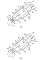
また、上記したケーブルクランプ7は、矩形の厚板状部材の片面に上記第1半円筒部18と対称形をなすようにケーブル6の外周面の半周分に対応する半円筒状に凹設された第2半円筒部19を有する形状に形成されている。図6に併せて示されるように、ケーブルクランプ7の半円筒状の内周面には、軸線方向(ケーブル6の軸線方向)中間部に周方向に延在する円弧状突条14aが設けられていると共に、内壁3cの内部側となる軸線方向端部に上記と同様の形状で互いに隣接する一対の円弧状突条14bが設けられている。また、ケーブルクランプ7の外面における凹設部3dに没入する没入方向端面と両側面とに、上記一対の円弧状突条14bに対応する位置に突壁部14cが設けられている。
The
上記第1半円筒部18の内周面には、半円筒の軸線方向(ケーブル6の軸線方向)中間部にて半周方向に延在する一対の円弧状突条14dが設けられていると共に、内壁3eの内側となる軸線方向端部にて半周方向に延在しかつ互いに隣接する一対の円弧状突条14eが設けられている。また、凹設部3dにおけるケーブルクランプ6を受容する直方体状部分において、ケーブルクランプ7を受け止める両側の段部と、ケーブルクランプ7を側方から挟む側面とに、上記突壁部14cを嵌合状態に受容する溝14fが設けられている。
On the inner peripheral surface of the first
なお、ケーブルクランプ7の両側壁部分の外側面に係合爪7aが形成され、凹設部3dの対応する両内側壁面に係合凹部3fが形成されており、ケーブルクランプ7を凹設部3fに没入させることにより係合爪7aと係合凹部3fとが係合し、ボディ3にケーブルクランプ7が組み付けられる。
The engaging claws 7a are formed on the outer side surfaces of the both side wall portions of the
このようにして、凹設部3dとケーブルクランプ7との各半円筒部18・19によりケーブル6を外囲する形で挟持することができ、かつ各半円筒部18・19の内周面に設けている各円弧状突条14a・14b・14d・14eがケーブル5の被覆の外周面に対して全周に亘って径方向に食い込むようになる(図7参照)。これにより、ポッティング液がケーブル5の外周面を軸線方向に伝わって漏れ出ようとする場合に、内壁2c側の各円弧状突条14b・14eにて遮断し得ると共に、さらに外側の各円弧状突条14a・14dでも遮断する二重遮断構造としていることから、ポッティング液の漏洩を確実に防止することができる。さらに、ケーブルクランプ7の突壁部14cと凹設部3dの溝14fとの嵌合部分がラビリンス構造となり、ケーブルクランプ7と凹設部3dとの隙間からの漏れも防止される。
In this way, the
また、各半円筒部18・19による挟持状態では、ケーブル6の被覆の弾性復元力によりケーブルクランプ7が凹設部3dから押し出される向きの付勢力を受けるが、その付勢方向は係合爪7aが係合凹部3fに係合力を増す向きとなる。したがって、係合爪7aと係合凹部3fとの係合力がより一層強固なものとなり、ケーブルクランプ7の固定状態がより一層強固なものとなる。また、第1半円筒部18に設けられた上記一対の円弧状突条14dは第2半円筒部19の円弧状突状14aに対して軸線方向に異なりかつ互い違いに位置するように配設されている。これにより、ケーブル6を蛇行状態で径方向に挟持することになる。
Further, in the clamped state between the
さらに、図7に示されるように、円弧状突状14dの断面形状は台形に形成され、かつ台形における第1半円筒部18の内周面に直交する壁面15が、ケーブル6が引き抜かれる方向(図の矢印C)とは相反する側に設けられている。このように、円弧状突条14dの突出方向端部のケーブル6の引き抜き方向とは相反する側に、直角となる角部が形成されている。これにより、ケーブル6に外力による引き抜き力が加わっても、角部15にケーブル6の外周面が食い込んで抵抗となり、ケーブル6の抜け止めが強固なものとなる。このように、各円弧状突状14a・14dの好適な配置及び形状により、ケーブルクランプ6と凹設部3dとによる挟持力を高めることなく、ケーブル6の耐引き抜き力を高めることができるため、ケーブルクランプ6の凹設部3dとの間の挟持方向の荷重を小さくすることができる。したがって、ケーブルクランプ7の凹設部3dへの組み付け力(図1の矢印B方向の挿入力)を軽減することができ、組み付け作業性が向上し得る。なお、角部15の角度は図示例では直角としたが、直角を含む鋭角であれば良い。
Further, as shown in FIG. 7, the cross-sectional shape of the
さらに、第1半円筒部18の内周面における一対の円弧状突条14dの間には軸線方向に延在する互いに平行な一対の軸線方向突条14gが設けられている。これら一対の軸線方向突条14gは、第2半円筒部19の円弧状突条14aに対向する位置に設けられており、ケーブルクランプ7の組み付け状態で円弧状突条14aと軸線方向突条14gとによりケーブル6の径方向対称位置が押圧される。これにより、ケーブル6の軸線周りの変位が防止され、ケーブル6が、ケーブルクランプ7と凹設部3dとにより強固に固定される。
Further, between the pair of arc-shaped
また、図6及び図8(ケーブル6は図示省略)に示されるように、第2半円筒部19の円弧状突条14bの周方向端面16が円弧状突条14bの円の接線に直交する面で形成されているのに対して、円弧状突条14dの周方向端面17は、周方向端面16に対して後退する傾斜面により形成されている。これにより、ケーブルクランプ7を凹設部3dに組み付けた状態で、両円弧状突条14b・14eの互いに対向する両周方向端面16・17間に楔形の隙間が形成され、両端面16・17がケーブル6の外周面に対して拡開状になるため、両円弧状突条14b・14eによりケーブル6を押圧して挟持した場合にケーブル6の被覆の一部が膨出するように変形しても、その膨出部分が両周方向端面16・17間の隙間に逃げることができ、凹設部3dとケーブルクランプ7との合わせ面によりケーブル6の被覆を挟み込んで傷付けてしまうことがないと共に、挟み込んだ場合のポッティング液の漏洩を防止し得る。
Further, as shown in FIGS. 6 and 8 (the
1 端子ボックス
3 ボディ
3d 凹設部
5 端子
6 ケーブル
7 ケーブルクランプ
14a・14b・14c・14d・14e 円弧状突条
15 角部
15・16 周方向端面
18 第1半円筒部
19 第2半円筒部
DESCRIPTION OF
Claims (4)
前記端子ボックスが、前記端子を受容する箱状の本体と、前記本体から外方に延出される前記ケーブルを通すべく前記本体に設けられた半円筒凹設状の第1半円筒部と、前記第1半円筒部との間に前記ケーブルを挟持するように形成された半円筒凹設状の第2半円筒部を有しかつ前記本体に取り付けられたケーブルクランプとを有し、
前記第1半円筒部と前記第2半円筒部との各内周面に、前記本体に前記ケーブルクランプが取り付けられた状態で前記ケーブルの軸線方向に異なる位置で互い違いに前記ケーブルの外周面を径方向に押圧するための複数の円弧状突条が配設されていることを特徴とする端子ボックス。 A terminal box for receiving and fixing a terminal combined with an external connection cable,
The terminal box has a box-shaped main body for receiving the terminal; a semi-cylindrical concave first semi-cylindrical portion provided in the main body to pass the cable extending outward from the main body; A cable clamp having a semi-cylindrical recessed second semi-cylindrical portion formed so as to sandwich the cable between the first semi-cylindrical portion and attached to the body;
The outer peripheral surfaces of the cables are staggered at different positions in the axial direction of the cable in a state where the cable clamp is attached to the main body on the inner peripheral surfaces of the first semi-cylindrical portion and the second semi-cylindrical portion. A terminal box having a plurality of arc-shaped protrusions for pressing in a radial direction.
前記2つ以上の円弧状突条の少なくとも1つの隣り合う間に前記両半円筒部の軸線方向に沿うように延在する軸線方向突条が設けられていることを特徴とする請求項1または請求項2に記載の端子ボックス。 Two or more arc-shaped protrusions are provided on at least one inner peripheral surface of the first semi-cylindrical portion and the second semi-cylindrical portion,
The axial ridge extending so as to extend along the axial direction of the semi-cylindrical parts is provided between at least one of the two or more arc-shaped ridges. The terminal box according to claim 2.
前記端子ボックスが、前記端子を受容する箱状の本体と、前記本体から外方に延出される前記ケーブルを通すべく前記本体に設けられた半円筒凹設状の第1半円筒部と、前記第1半円筒部との間に前記ケーブルを挟持するように形成された半円筒凹設状の第2半円筒部を有しかつ前記本体に取り付けられたケーブルクランプとを有し、
前記第1半円筒部と前記第2半円筒部との各内周面に、前記本体に前記ケーブルクランプが取り付けられた状態で前記ケーブルの外周面に全周に亘って食い込むようにそれぞれ突設された各円弧状突条が互いに周方向に連続するように設けられ、
前記各円弧状突条の互いに対向する各周方向端面が前記ケーブルの外周面に向けて拡開するように形成されていることを特徴とする端子ボックス。 A terminal box for receiving and fixing a terminal combined with an external connection cable,
The terminal box has a box-shaped main body for receiving the terminal; a semi-cylindrical concave first semi-cylindrical portion provided in the main body to pass the cable extending outward from the main body; A cable clamp having a semi-cylindrical recessed second semi-cylindrical portion formed so as to sandwich the cable between the first semi-cylindrical portion and attached to the body;
Projecting on the inner peripheral surfaces of the first semi-cylindrical portion and the second semi-cylindrical portion so as to bite into the outer peripheral surface of the cable over the entire circumference in a state where the cable clamp is attached to the main body. Each arc-shaped ridge is made to be continuous in the circumferential direction,
A terminal box, wherein each circumferential end face of each arcuate ridge facing each other is formed to expand toward an outer peripheral face of the cable.
Priority Applications (1)
| Application Number | Priority Date | Filing Date | Title |
|---|---|---|---|
| JP2011050526A JP5670228B2 (en) | 2011-03-08 | 2011-03-08 | Terminal box |
Applications Claiming Priority (1)
| Application Number | Priority Date | Filing Date | Title |
|---|---|---|---|
| JP2011050526A JP5670228B2 (en) | 2011-03-08 | 2011-03-08 | Terminal box |
Publications (2)
| Publication Number | Publication Date |
|---|---|
| JP2012190838A true JP2012190838A (en) | 2012-10-04 |
| JP5670228B2 JP5670228B2 (en) | 2015-02-18 |
Family
ID=47083729
Family Applications (1)
| Application Number | Title | Priority Date | Filing Date |
|---|---|---|---|
| JP2011050526A Active JP5670228B2 (en) | 2011-03-08 | 2011-03-08 | Terminal box |
Country Status (1)
| Country | Link |
|---|---|
| JP (1) | JP5670228B2 (en) |
Cited By (4)
| Publication number | Priority date | Publication date | Assignee | Title |
|---|---|---|---|---|
| JP2015029409A (en) * | 2013-06-27 | 2015-02-12 | 京セラ株式会社 | Solar cell module |
| JP2015125978A (en) * | 2013-12-27 | 2015-07-06 | 古河電気工業株式会社 | Wire harness, method of connecting coated lead wire, and wire harness structure |
| CN106452349A (en) * | 2016-12-19 | 2017-02-22 | 芜湖光荣网络科技有限公司 | Battery arrangement structure in double current solar photovoltaic module |
| JP2018193857A (en) * | 2017-05-12 | 2018-12-06 | 株式会社鶴見製作所 | Submerged motor-driven pump |
Citations (7)
| Publication number | Priority date | Publication date | Assignee | Title |
|---|---|---|---|---|
| JPH06181079A (en) * | 1992-12-15 | 1994-06-28 | Matsushita Electric Works Ltd | Modular plug |
| JPH087968A (en) * | 1994-06-17 | 1996-01-12 | Fujikura Ltd | Connector and its assembling method |
| JPH1126035A (en) * | 1997-07-04 | 1999-01-29 | Engel Kogyo Kk | Terminal box for solar cell module |
| JP2000299485A (en) * | 1999-04-15 | 2000-10-24 | Oonanba Kk | Connection terminal box of solar battery module |
| JP2003257511A (en) * | 2002-02-27 | 2003-09-12 | Auto Network Gijutsu Kenkyusho:Kk | Wire connection structure |
| JP2007134462A (en) * | 2005-11-09 | 2007-05-31 | Sumitomo Wiring Syst Ltd | Terminal box for solar cell module |
| JP2010118525A (en) * | 2008-11-13 | 2010-05-27 | Yukita Electric Wire Co Ltd | Terminal box for solar cell module |
-
2011
- 2011-03-08 JP JP2011050526A patent/JP5670228B2/en active Active
Patent Citations (7)
| Publication number | Priority date | Publication date | Assignee | Title |
|---|---|---|---|---|
| JPH06181079A (en) * | 1992-12-15 | 1994-06-28 | Matsushita Electric Works Ltd | Modular plug |
| JPH087968A (en) * | 1994-06-17 | 1996-01-12 | Fujikura Ltd | Connector and its assembling method |
| JPH1126035A (en) * | 1997-07-04 | 1999-01-29 | Engel Kogyo Kk | Terminal box for solar cell module |
| JP2000299485A (en) * | 1999-04-15 | 2000-10-24 | Oonanba Kk | Connection terminal box of solar battery module |
| JP2003257511A (en) * | 2002-02-27 | 2003-09-12 | Auto Network Gijutsu Kenkyusho:Kk | Wire connection structure |
| JP2007134462A (en) * | 2005-11-09 | 2007-05-31 | Sumitomo Wiring Syst Ltd | Terminal box for solar cell module |
| JP2010118525A (en) * | 2008-11-13 | 2010-05-27 | Yukita Electric Wire Co Ltd | Terminal box for solar cell module |
Cited By (4)
| Publication number | Priority date | Publication date | Assignee | Title |
|---|---|---|---|---|
| JP2015029409A (en) * | 2013-06-27 | 2015-02-12 | 京セラ株式会社 | Solar cell module |
| JP2015125978A (en) * | 2013-12-27 | 2015-07-06 | 古河電気工業株式会社 | Wire harness, method of connecting coated lead wire, and wire harness structure |
| CN106452349A (en) * | 2016-12-19 | 2017-02-22 | 芜湖光荣网络科技有限公司 | Battery arrangement structure in double current solar photovoltaic module |
| JP2018193857A (en) * | 2017-05-12 | 2018-12-06 | 株式会社鶴見製作所 | Submerged motor-driven pump |
Also Published As
| Publication number | Publication date |
|---|---|
| JP5670228B2 (en) | 2015-02-18 |
Similar Documents
| Publication | Publication Date | Title |
|---|---|---|
| US7920385B2 (en) | Terminal box for solar cell module | |
| JP5759119B2 (en) | Terminal box potting liquid leakage prevention structure | |
| US7369398B2 (en) | Terminal box and a method of providing it | |
| US8647160B2 (en) | Connection terminal, terminal connection structure, and terminal box | |
| EP1594169A2 (en) | A terminal box for a solar battery module, a rectifying-device unit and a method of assembling a terminal box | |
| JP5670228B2 (en) | Terminal box | |
| KR20090096732A (en) | Battery pack | |
| JP5825991B2 (en) | Wire cabling structure for storage batteries | |
| WO2012105491A1 (en) | Electrical storage element | |
| JP2012190835A (en) | Terminal for terminal box | |
| KR101482583B1 (en) | Connecting structure and connecting method of fiber conductor wire | |
| JP2010067478A (en) | Terminal fitting, and electric wire with terminal fitting | |
| JP5608002B2 (en) | Terminal box | |
| KR101215183B1 (en) | terminal box | |
| CN214412483U (en) | Inlet wire connection structure of starter | |
| CN215184555U (en) | Connecting terminal, charging seat and electric automobile | |
| JP2006059990A (en) | Terminal box for solar cell module | |
| JP5564678B2 (en) | Connection structure for connectors and stacked electrodes | |
| JP6307573B1 (en) | Cable fixing structure | |
| JP5541597B2 (en) | Output cable fixing structure of terminal box for solar cell module | |
| JP4948492B2 (en) | Diode connection structure of terminal box for solar cell module | |
| EP3937315A1 (en) | Retention clip for a mechanical strain relief of a cable and cable assembly as well as connector with such a retention clip | |
| JP5890637B2 (en) | Terminal member mounting structure in terminal box | |
| JP2006041262A (en) | Terminal box for solar cell module | |
| JP2005353734A (en) | Terminal box for solar cell module |
Legal Events
| Date | Code | Title | Description |
|---|---|---|---|
| A621 | Written request for application examination |
Free format text: JAPANESE INTERMEDIATE CODE: A621 Effective date: 20140304 |
|
| A131 | Notification of reasons for refusal |
Free format text: JAPANESE INTERMEDIATE CODE: A131 Effective date: 20140617 |
|
| A977 | Report on retrieval |
Free format text: JAPANESE INTERMEDIATE CODE: A971007 Effective date: 20140618 |
|
| A521 | Request for written amendment filed |
Free format text: JAPANESE INTERMEDIATE CODE: A523 Effective date: 20140807 |
|
| TRDD | Decision of grant or rejection written | ||
| A01 | Written decision to grant a patent or to grant a registration (utility model) |
Free format text: JAPANESE INTERMEDIATE CODE: A01 Effective date: 20141202 |
|
| A61 | First payment of annual fees (during grant procedure) |
Free format text: JAPANESE INTERMEDIATE CODE: A61 Effective date: 20141217 |
|
| R150 | Certificate of patent or registration of utility model |
Ref document number: 5670228 Country of ref document: JP Free format text: JAPANESE INTERMEDIATE CODE: R150 |
|
| S531 | Written request for registration of change of domicile |
Free format text: JAPANESE INTERMEDIATE CODE: R313531 |
|
| R350 | Written notification of registration of transfer |
Free format text: JAPANESE INTERMEDIATE CODE: R350 |
|
| R250 | Receipt of annual fees |
Free format text: JAPANESE INTERMEDIATE CODE: R250 |
|
| R250 | Receipt of annual fees |
Free format text: JAPANESE INTERMEDIATE CODE: R250 |
|
| R250 | Receipt of annual fees |
Free format text: JAPANESE INTERMEDIATE CODE: R250 |
|
| R250 | Receipt of annual fees |
Free format text: JAPANESE INTERMEDIATE CODE: R250 |
|
| R250 | Receipt of annual fees |
Free format text: JAPANESE INTERMEDIATE CODE: R250 |
|
| R250 | Receipt of annual fees |
Free format text: JAPANESE INTERMEDIATE CODE: R250 |
|
| R250 | Receipt of annual fees |
Free format text: JAPANESE INTERMEDIATE CODE: R250 |