JP2012189376A - Rotation angle detection device and torque detection device - Google Patents
Rotation angle detection device and torque detection device Download PDFInfo
- Publication number
- JP2012189376A JP2012189376A JP2011051638A JP2011051638A JP2012189376A JP 2012189376 A JP2012189376 A JP 2012189376A JP 2011051638 A JP2011051638 A JP 2011051638A JP 2011051638 A JP2011051638 A JP 2011051638A JP 2012189376 A JP2012189376 A JP 2012189376A
- Authority
- JP
- Japan
- Prior art keywords
- magnetic
- magnetic pole
- rotation angle
- pole pair
- detection device
- Prior art date
- Legal status (The legal status is an assumption and is not a legal conclusion. Google has not performed a legal analysis and makes no representation as to the accuracy of the status listed.)
- Withdrawn
Links
- 238000001514 detection method Methods 0.000 title claims abstract description 112
- 238000004364 calculation method Methods 0.000 claims description 184
- 238000006073 displacement reaction Methods 0.000 claims description 2
- 230000005405 multipole Effects 0.000 claims 1
- 238000000034 method Methods 0.000 description 108
- 230000008569 process Effects 0.000 description 95
- 238000010586 diagram Methods 0.000 description 17
- 230000008859 change Effects 0.000 description 5
- 230000003247 decreasing effect Effects 0.000 description 2
- 230000006870 function Effects 0.000 description 2
- 230000009471 action Effects 0.000 description 1
- 230000004044 response Effects 0.000 description 1
- 238000004804 winding Methods 0.000 description 1
Images


Classifications
-
- G—PHYSICS
- G01—MEASURING; TESTING
- G01D—MEASURING NOT SPECIALLY ADAPTED FOR A SPECIFIC VARIABLE; ARRANGEMENTS FOR MEASURING TWO OR MORE VARIABLES NOT COVERED IN A SINGLE OTHER SUBCLASS; TARIFF METERING APPARATUS; MEASURING OR TESTING NOT OTHERWISE PROVIDED FOR
- G01D5/00—Mechanical means for transferring the output of a sensing member; Means for converting the output of a sensing member to another variable where the form or nature of the sensing member does not constrain the means for converting; Transducers not specially adapted for a specific variable
- G01D5/12—Mechanical means for transferring the output of a sensing member; Means for converting the output of a sensing member to another variable where the form or nature of the sensing member does not constrain the means for converting; Transducers not specially adapted for a specific variable using electric or magnetic means
- G01D5/244—Mechanical means for transferring the output of a sensing member; Means for converting the output of a sensing member to another variable where the form or nature of the sensing member does not constrain the means for converting; Transducers not specially adapted for a specific variable using electric or magnetic means influencing characteristics of pulses or pulse trains; generating pulses or pulse trains
- G01D5/245—Mechanical means for transferring the output of a sensing member; Means for converting the output of a sensing member to another variable where the form or nature of the sensing member does not constrain the means for converting; Transducers not specially adapted for a specific variable using electric or magnetic means influencing characteristics of pulses or pulse trains; generating pulses or pulse trains using a variable number of pulses in a train
- G01D5/2454—Encoders incorporating incremental and absolute signals
- G01D5/2455—Encoders incorporating incremental and absolute signals with incremental and absolute tracks on the same encoder
- G01D5/2457—Incremental encoders having reference marks
-
- G—PHYSICS
- G01—MEASURING; TESTING
- G01D—MEASURING NOT SPECIALLY ADAPTED FOR A SPECIFIC VARIABLE; ARRANGEMENTS FOR MEASURING TWO OR MORE VARIABLES NOT COVERED IN A SINGLE OTHER SUBCLASS; TARIFF METERING APPARATUS; MEASURING OR TESTING NOT OTHERWISE PROVIDED FOR
- G01D5/00—Mechanical means for transferring the output of a sensing member; Means for converting the output of a sensing member to another variable where the form or nature of the sensing member does not constrain the means for converting; Transducers not specially adapted for a specific variable
- G01D5/12—Mechanical means for transferring the output of a sensing member; Means for converting the output of a sensing member to another variable where the form or nature of the sensing member does not constrain the means for converting; Transducers not specially adapted for a specific variable using electric or magnetic means
- G01D5/14—Mechanical means for transferring the output of a sensing member; Means for converting the output of a sensing member to another variable where the form or nature of the sensing member does not constrain the means for converting; Transducers not specially adapted for a specific variable using electric or magnetic means influencing the magnitude of a current or voltage
- G01D5/142—Mechanical means for transferring the output of a sensing member; Means for converting the output of a sensing member to another variable where the form or nature of the sensing member does not constrain the means for converting; Transducers not specially adapted for a specific variable using electric or magnetic means influencing the magnitude of a current or voltage using Hall-effect devices
- G01D5/145—Mechanical means for transferring the output of a sensing member; Means for converting the output of a sensing member to another variable where the form or nature of the sensing member does not constrain the means for converting; Transducers not specially adapted for a specific variable using electric or magnetic means influencing the magnitude of a current or voltage using Hall-effect devices influenced by the relative movement between the Hall device and magnetic fields
-
- G—PHYSICS
- G01—MEASURING; TESTING
- G01L—MEASURING FORCE, STRESS, TORQUE, WORK, MECHANICAL POWER, MECHANICAL EFFICIENCY, OR FLUID PRESSURE
- G01L3/00—Measuring torque, work, mechanical power, or mechanical efficiency, in general
- G01L3/02—Rotary-transmission dynamometers
- G01L3/04—Rotary-transmission dynamometers wherein the torque-transmitting element comprises a torsionally-flexible shaft
- G01L3/10—Rotary-transmission dynamometers wherein the torque-transmitting element comprises a torsionally-flexible shaft involving electric or magnetic means for indicating
- G01L3/101—Rotary-transmission dynamometers wherein the torque-transmitting element comprises a torsionally-flexible shaft involving electric or magnetic means for indicating involving magnetic or electromagnetic means
- G01L3/104—Rotary-transmission dynamometers wherein the torque-transmitting element comprises a torsionally-flexible shaft involving electric or magnetic means for indicating involving magnetic or electromagnetic means involving permanent magnets
-
- G—PHYSICS
- G01—MEASURING; TESTING
- G01L—MEASURING FORCE, STRESS, TORQUE, WORK, MECHANICAL POWER, MECHANICAL EFFICIENCY, OR FLUID PRESSURE
- G01L3/00—Measuring torque, work, mechanical power, or mechanical efficiency, in general
- G01L3/02—Rotary-transmission dynamometers
- G01L3/04—Rotary-transmission dynamometers wherein the torque-transmitting element comprises a torsionally-flexible shaft
- G01L3/10—Rotary-transmission dynamometers wherein the torque-transmitting element comprises a torsionally-flexible shaft involving electric or magnetic means for indicating
- G01L3/109—Rotary-transmission dynamometers wherein the torque-transmitting element comprises a torsionally-flexible shaft involving electric or magnetic means for indicating involving measuring phase difference of two signals or pulse trains
Abstract
Description
この発明は、ブラシレスモータのロータ等の回転体の回転角を検出する回転角検出装置およびトルク検出装置に関する。 The present invention relates to a rotation angle detection device and a torque detection device that detect a rotation angle of a rotating body such as a rotor of a brushless motor.
電動パワーステアリング装置などに使用されるブラシレスモータを制御するためには、ロータの回転角度に合わせてステータ巻線に電流を通電する必要がある。そこで、ブラシレスモータの回転に応じて回転する検出用ロータを用いて、ブラシレスモータのロータの回転角を検出する回転角検出装置が知られている。具体的には、図13に示すように、検出用ロータ101(以下、「ロータ101」という)は、ブラシレスモータのロータに設けられている磁極対に相当する複数の磁極対を有する円筒状の磁石102を備えている。ロータ101の周囲には、2つの磁気センサ121,122が、ロータ101の回転中心軸を中心として所定の角度間隔をおいて配置されている。各磁気センサ121,122からは、所定の位相差を有する正弦波信号が出力される。これらの2つの正弦波信号に基づいて、ロータ101の回転角(ブラシレスモータのロータの回転角)が検出される。
In order to control a brushless motor used in an electric power steering device or the like, it is necessary to apply a current to the stator winding in accordance with the rotation angle of the rotor. Therefore, a rotation angle detection device that detects a rotation angle of a brushless motor rotor using a detection rotor that rotates in accordance with the rotation of the brushless motor is known. Specifically, as shown in FIG. 13, the detection rotor 101 (hereinafter referred to as “
この例では、磁石102は、5組の磁極対を有している。つまり、磁石102は、等角度間隔で配置された10個の磁極を有している。各磁極は、ロータ101の回転中心軸を中心として、36°(電気角では180°)の角度間隔で配置されている。また、2つの磁気センサ121,122は、ロータ101の回転中心軸を中心として18°(電気角では90°)の角度間隔をおいて配置されている。
In this example, the
図13に矢印で示す方向を検出用ロータ101の正方向の回転方向とする。そして、ロータ101が正方向に回転されるとロータ101の回転角が大きくなり、ロータ101が逆方向に回転されると、ロータ101の回転角が小さくなるものとする。各磁気センサ121,122からは、図14に示すように、ロータ101が1磁極対分に相当する角度(72°(電気角では360°))を回転する期間を一周期とする正弦波信号V1,V2が出力される。
A direction indicated by an arrow in FIG. 13 is a positive rotation direction of the
ロータ101の1回転分の角度範囲を、5つの磁極対に対応して5つの区間に分け、各区間の開始位置を0°とし終了位置を360°として表したロータ101の角度を、ロータ101の電気角θeということにする。
ここでは、第1の磁気センサ121からは、V1=A1・sinθeの出力信号が出力され、第2の磁気センサ122からは、V2=A2・cosθeの出力信号が出力されるものとする。A1,A2は、振幅である。両出力信号V1,V2の振幅A1,A2が互いに等しいとみなすと、ロータ101の電気角θeは、両出力信号V1,V2を用いて、次式(1)に基づいて求めることができる。
The angle range for one rotation of the
Here, it is assumed that an output signal of V1 = A1 · sin θe is output from the first
θe=tan−1(sinθe/cosθe)
=tan−1(V1/V2) …(1)
このようにして、求められた電気角θeを使って、ブラシレスモータを制御する。
θe = tan −1 (sin θe / cos θe)
= Tan -1 (V1 / V2) (1)
In this way, the brushless motor is controlled using the obtained electrical angle θe.
前述したような従来の回転角検出装置においては、磁極ごとの磁力のばらつきなどにより、各磁気センサ121,122の出力信号V1,V2の振幅が磁極ごとに変動するため、ロータ101の回転角の検出に誤差が発生する。そこで、ロータ101の機械角に応じて、各磁気センサ121,122の出力信号V1,V2の振幅が等しくなるように、各磁気センサ121,122の出力信号V1,V2を補正(振幅補正)した後、ロータ101の電気角θeを演算することが考えられる。
In the conventional rotation angle detection device as described above, the amplitudes of the output signals V1 and V2 of the
磁極毎に磁力がばらつく場合には、各磁気センサ121,122の出力信号V1,V2に対して、電気角の1周期または半周期ごとに振幅を補正するために用いられる振幅補正値を変更しなければならない。したがって、このような振幅補正を行うためには、各磁気センサ121,122が感知している磁極を特定する必要がある。ロータ101が1回転した後においては、各磁極のピーク値の違いから各磁気センサ121,122が感知している磁極を特定することができるので、各磁気センサ121,122が感知している磁極に応じた振幅補正を行うことができる。しかしなから、ブラシモータの起動直後には、各磁気センサ121,122が感知している磁極を特定することができないため、各磁気センサ121,122が感知している磁極に応じた振幅補正を行うことができない。
When the magnetic force varies for each magnetic pole, the amplitude correction value used for correcting the amplitude for each cycle or half cycle of the electrical angle is changed for the output signals V1 and V2 of the
なお、電動パワーステアリング装置などに使用されるトルク検出装置は、入力軸と出力軸とを連結するトーションバーの捩れ角を検出することにより、入力軸に加えられたトルクを演算する構成となっている。トーションバーの捩れ角は、入力軸の回転角と出力軸の回転角との差に応じた値となる。そこで、入力軸および出力軸の回転角を従来の回転角検出装置と同様な方法で検出し、検出された入力軸および出力軸の回転角の差に基づいて、入力軸に加えられたトルクを演算することが考えられる。 A torque detection device used for an electric power steering device or the like is configured to calculate a torque applied to the input shaft by detecting a twist angle of a torsion bar that connects the input shaft and the output shaft. Yes. The torsion angle of the torsion bar is a value corresponding to the difference between the rotation angle of the input shaft and the rotation angle of the output shaft. Therefore, the rotation angle of the input shaft and the output shaft is detected by the same method as that of the conventional rotation angle detection device, and the torque applied to the input shaft is calculated based on the detected difference between the rotation angles of the input shaft and the output shaft. It is possible to calculate.
この発明の目的は、回転体が回転を開始した直後の早い段階で、磁気センサが感知している磁極を特定できるようになる回転角検出装置およびトルク検出装置を提供することである。 An object of the present invention is to provide a rotation angle detection device and a torque detection device that can identify a magnetic pole sensed by a magnetic sensor at an early stage immediately after the rotating body starts to rotate.
上記の目的を達成するための請求項1記載の発明は、回転体(10)の回転角を検出する回転角検出装置であって、
前記回転体(10)の回転に応じて回転し、第1の磁力を有する1または複数の磁極対と第2の磁力を有する1または複数の磁極対とを備えている多極磁石(2)と、前記多極磁石の回転に応じて、互いに位相差を有する複数の正弦波信号をそれぞれ出力する複数の磁気センサ(21,22,23)と、各磁気センサの出力信号のピーク値をそれぞれ検出するピーク値検出手段(20,S7)と、前記ピーク値検出手段によって検出された各磁気センサのピーク値の組み合わせに基づいて、基準となる1つの磁気センサが感知している磁極対を特定する磁極対特定手段(20,S10)とを含み、各磁気センサのピーク値の組み合わせが、前記基準となる磁気センサが感知している磁極対毎に異なるように、前記磁極対の数、前記磁気センサの数、前記第1の磁力を有する磁極対と前記第2の磁力を有する磁極対との配列パターンおよび前記磁気センサの配置位置が設定されている、回転角検出装置である。なお、括弧内の英数字は、後述の実施形態における対応構成要素等を表すが、むろん、この発明の範囲は当該実施形態に限定されない。以下、この項において同じ。
The invention according to
A multipolar magnet (2) that rotates in response to the rotation of the rotating body (10) and includes one or more magnetic pole pairs having a first magnetic force and one or more magnetic pole pairs having a second magnetic force And a plurality of magnetic sensors (21, 22, 23) that respectively output a plurality of sine wave signals having phase differences according to the rotation of the multipolar magnet, and the peak value of the output signal of each magnetic sensor, respectively Based on the combination of the peak value detecting means (20, S7) to be detected and the peak value of each magnetic sensor detected by the peak value detecting means, the magnetic pole pair sensed by one reference magnetic sensor is specified. Magnetic pole pair specifying means (20, S10), and the number of the magnetic pole pairs, so that the combination of peak values of the magnetic sensors is different for each magnetic pole pair sensed by the reference magnetic sensor, Magnetic sensor The number, arrangement pattern and the arrangement position of the magnetic sensor with the pole pair having the second magnetic pole pair having a first magnetic force is set, a rotation angle detecting device. In addition, although the alphanumeric character in parentheses represents a corresponding component in an embodiment described later, of course, the scope of the present invention is not limited to the embodiment. The same applies hereinafter.
ピーク値検出手段によって、各磁気センサの出力信号のピーク値がそれぞれ検出される。そして、各磁気センサのピーク値の組み合わせに基づいて、基準となる1つの磁気センサが感知している磁極対が特定される。これにより、各磁気センサが感知している磁極を特定することが可能となる。したがって、各磁気センサの出力信号の振幅を補正することが可能となる。これにより、振幅補正後の少なくとも2つの出力信号に基づいて、回転体の回転角を演算することが可能となる。 The peak value detection means detects the peak value of the output signal of each magnetic sensor. Based on the combination of peak values of each magnetic sensor, the magnetic pole pair sensed by one reference magnetic sensor is specified. Thereby, it is possible to specify the magnetic pole sensed by each magnetic sensor. Therefore, it is possible to correct the amplitude of the output signal of each magnetic sensor. Thereby, the rotation angle of the rotating body can be calculated based on at least two output signals after amplitude correction.
この発明では、ピーク値検出手段によって、各磁気センサの出力信号のピーク値がそれぞれ検出されたときに、各磁気センサが感知している磁極を特定することが可能となる。これにより、回転体が回転を開始した後、回転体が1回転する前に、各磁気センサが感知している磁極を特定することができる。つまり、回転体が回転を開始した直後の早い段階で、磁気センサが感知している磁極を特定できるようになる。これにより、回転体が回転を開始した直後の早い段階で、回転角の絶対的回転角(機械角)を検出することが可能となる。 In the present invention, when the peak value of the output signal of each magnetic sensor is detected by the peak value detecting means, the magnetic pole sensed by each magnetic sensor can be specified. As a result, the magnetic pole sensed by each magnetic sensor can be specified after the rotating body starts rotating and before the rotating body makes one rotation. That is, the magnetic pole sensed by the magnetic sensor can be identified at an early stage immediately after the rotating body starts rotating. This makes it possible to detect the absolute rotation angle (mechanical angle) of the rotation angle at an early stage immediately after the rotating body starts rotating.
請求項2記載の発明は、前記磁極対特定手段の磁極対特定結果に基づいて、少なくとも2つの磁気センサが感知している磁極を特定する磁極特定手段(20,S10)と、前記磁極特定手段の磁極特定結果に基づいて、少なくとも2つの磁気センサの出力信号の振幅を補正する振幅補正手段(20,S12)と、振幅補正手段によって振幅が補正された少なくとも2つの出力信号に基づいて、前記回転体の回転角を検出する回転角演算手段(20,S13,S14)とを、さらに含む請求項1に記載の回転角検出装置である。
According to a second aspect of the present invention, the magnetic pole specifying means (20, S10) for specifying the magnetic pole sensed by at least two magnetic sensors based on the magnetic pole pair specifying result of the magnetic pole pair specifying means, and the magnetic pole specifying means Based on the magnetic pole identification result, the amplitude correction means (20, S12) for correcting the amplitude of the output signals of at least two magnetic sensors, and the at least two output signals whose amplitudes are corrected by the amplitude correction means, The rotation angle detection device according to
この構成では、磁極対特定手段の磁極対特定結果に基づいて、少なくとも2つの磁気センサが感知している磁極が特定される。この特定結果に基づいて、少なくとも2つの磁気センサの出力信号の振幅が補正される。そして、振幅が補正された少なくとも2つの出力信号に基づいて、前記回転体の回転角が検出される。
請求項3記載の発明は、前記複数の磁極対は、第1〜第8の8つの磁極対からなり、 前記複数の磁気センサは、第1〜第3の3つの磁気センサからなり、前記第1の磁気センサが前記第1の磁極対における電気角で0°に対向しているときには、前記第2の磁気センサが前記第2の磁極対における電気角で240°に対向し、前記第3の磁気センサが前記第3の磁極対における電気角で120°に対向するように、前記3つの磁気センサが配置されている、請求項1または2に記載の回転角検出装置である。
In this configuration, the magnetic pole sensed by at least two magnetic sensors is specified based on the magnetic pole pair specifying result of the magnetic pole pair specifying means. Based on this identification result, the amplitudes of the output signals of at least two magnetic sensors are corrected. Then, the rotation angle of the rotating body is detected based on at least two output signals whose amplitudes are corrected.
According to a third aspect of the present invention, the plurality of magnetic pole pairs are composed of first to eighth eight magnetic pole pairs, and the plurality of magnetic sensors are composed of first to third three magnetic sensors, When one magnetic sensor is opposed to 0 ° in electrical angle in the first magnetic pole pair, the second magnetic sensor is opposed to 240 ° in electrical angle in the second magnetic pole pair, and the third magnetic sensor The rotation angle detection device according to
請求項4記載の発明は、第1軸(52)と第2軸(51)とを連結する連結軸(53)を含み、前記連結軸の捩れに起因する前記第1軸と前記第2軸の相対的回転変位量に基づいて、前記第1軸と前記第2軸に加えられたトルクを検出するトルク検出装置であって、請求項1〜請求項3のいずれか一項に記載の回転角検出装置である基本の回転角検出装置と同じ構成または前記基本の回転角検出装置に対して前記多極磁石の構成以外は同じ構成を有し、前記第1軸の回転角を検出するための第1の回転角検出装置(2A,21,22,23,20A)と、前記基本の回転角検出装置に対して前記多極磁石の構成以外は同じ構成を有し、前記第2軸の回転角を検出するための第2の回転角検出装置(2B,24,25,26,20B)とを含み、前記第1の回転角検出装置における多極磁石(2A)は、前記基本の回転角検出装置における多極磁石の各磁極対が、当該磁極対と同じ磁力を有する1または複数の磁極対からなる構成を有しており、前記第1の回転角検出装置における磁極対特定手段は、前記基本の回転角検出装置における多極磁石における各磁極対に対応する角度領域を表す領域番号のうち、前記第1の回転角検出装置において基準となる磁気センサ(21)が感知している角度領域に対応する領域番号を特定するように構成されており、前記基本の回転角検出装置における複数の磁極対の配列を磁力の強弱の配列で表した磁極対パターンを基準磁極対パターンとすると、前記第2の回転角演算装置における多極磁石は、前記基準磁極対パターンがn(nは2以上の整数)回繰り返された磁極対パターンを有しており、前記第2の回転角検出装置における磁極対特定手段は、第1の磁極対特定手段(20B,S10B)と、第2の磁極対特定手段(20B,S10B)とを含み、前記第1の磁極対特定手段は、前記第2の回転角検出装置の多極磁石が有する磁極対パターンに含まれる各基準磁極対パターン内での各磁極対の順番を表す番号を相対的磁極対番号と定義すると、前記第2の回転角検出装置において基準となる磁気センサ(24)が感知している磁極対に対応する相対的磁極対番号を特定するように構成されており、前記第2の磁極対特定手段は、前記第1の磁極対特定手段によって特定された相対的磁極対番号と、前記第1の回転角演算装置における前記磁極対特定手段によって特定された領域番号とに基づいて、前記第2の回転角検出装置において基準となる磁気センサが感知している磁極対を特定するように構成されている、トルク検出装置である。
The invention according to
第1の回転角検出装置における多極磁石は、基本の回転角検出装置における多極磁石の各磁極対が、当該磁極対と同じ磁力を有する1または複数の磁極対からなる構成を有している。そして、第1の回転角検出装置における磁極対特定手段は、基本の回転角検出装置における多極磁石における各磁極対に対応する角度領域を表す領域番号のうち、第1の回転角検出装置において基準となる磁気センサが感知している角度領域に対応する領域番号を特定する。 The multipolar magnet in the first rotation angle detection device has a configuration in which each magnetic pole pair of the multipolar magnet in the basic rotation angle detection device is composed of one or more magnetic pole pairs having the same magnetic force as the magnetic pole pair. Yes. And the magnetic pole pair specifying means in the first rotation angle detection device is the first rotation angle detection device among the area numbers representing the angle regions corresponding to the magnetic pole pairs in the multipolar magnet in the basic rotation angle detection device. An area number corresponding to the angular area sensed by the reference magnetic sensor is specified.
基本の回転角検出装置における複数の磁極対の配列を磁力の強弱の配列で表した磁極対パターンを基準磁極対パターンとすると、第2の回転角演算装置における多極磁石は、基準磁極対パターンがn(nは2以上の整数)回繰り返された磁極対パターンを有している。つまり、第2の回転角演算装置における多極磁石には、基本の回転角検出装置における磁極対数のn(nは2以上の整数)倍に相当する数の磁極対が設けられている。 When the magnetic pole pair pattern in which the arrangement of the plurality of magnetic pole pairs in the basic rotation angle detection device is expressed by the arrangement of the strength of the magnetic force is a reference magnetic pole pair pattern, the multipolar magnet in the second rotation angle calculation device is the reference magnetic pole pair pattern. Has a magnetic pole pair pattern repeated n (n is an integer of 2 or more) times. In other words, the multipolar magnet in the second rotation angle calculation device is provided with a number of magnetic pole pairs corresponding to n (n is an integer of 2 or more) times the number of magnetic pole pairs in the basic rotation angle detection device.
第2の回転角検出装置における磁極対特定手段は、第1の磁極対特定手段と、第2の磁極対特定手段とを含んでいる。第1の磁極対特定手段は、第2の回転角検出装置の多極磁石が有する磁極対パターンに含まれる各基準磁極対パターン内での各磁極対の順番を表す番号を相対的磁極対番号と定義すると、第2の回転角検出装置において基準となる磁気センサが感知している磁極対に対応する相対的磁極対番号を特定する。第2の磁極対特定手段は、前記第1の磁極対特定手段によって特定された相対的磁極対番号と、第1の回転角演算装置における磁極対特定手段によって特定された領域番号とに基づいて、第2の回転角検出装置において基準となる磁気センサが感知している磁極対を特定する。 The magnetic pole pair specifying means in the second rotation angle detecting device includes first magnetic pole pair specifying means and second magnetic pole pair specifying means. The first magnetic pole pair specifying means assigns a number indicating the order of each magnetic pole pair in each reference magnetic pole pair pattern included in the magnetic pole pair pattern of the multipolar magnet of the second rotation angle detection device to the relative magnetic pole pair number. In this case, the relative magnetic pole pair number corresponding to the magnetic pole pair sensed by the reference magnetic sensor in the second rotation angle detection device is specified. The second magnetic pole pair specifying means is based on the relative magnetic pole pair number specified by the first magnetic pole pair specifying means and the area number specified by the magnetic pole pair specifying means in the first rotation angle calculation device. The magnetic pole pair sensed by the reference magnetic sensor in the second rotation angle detection device is specified.
この発明によれば、第2軸が回転を開始した直後の早い段階で、第2の回転角検出装置において基準となる磁気センサが感知している磁極対を特定できるようになる。これにより、第2軸が回転を開始した直後の早い段階で、第2軸の絶対的回転角(機械角)を検出することが可能となる。
請求項5記載の発明は、車両操舵装置におけるトルク検出装置であって、前記第2の回転角検出装置は、前記第2軸の回転角を操舵角として検出するように構成されている、請求項4に記載のトルク検出装置である。この構成では、第2軸が回転を開始した直後の早い段階で、操舵角を演算できるようになる。
According to the present invention, the magnetic pole pair sensed by the magnetic sensor serving as a reference in the second rotation angle detection device can be specified at an early stage immediately after the second shaft starts to rotate. This makes it possible to detect the absolute rotation angle (mechanical angle) of the second axis at an early stage immediately after the second axis starts rotating.
The invention according to
以下では、この発明の実施形態について、添付図面を参照して詳細に説明する。
図1は、この発明をブラシレスモータのロータの回転角を検出するための回転角検出装置に適用した場合の第1の実施形態の構成を示す模式図である。
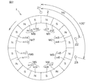
この回転角検出装置は、ブラシレスモータ10の回転に応じて回転する検出用ロータ(以下、単に「ロータ1」という)を有している。図2に示すように、ロータ1は、ブラシレスモータ10のロータに設けられている磁極対に相当する複数の磁極対を有する円筒状の磁石(多極磁石)2を含んでいる。
Hereinafter, embodiments of the present invention will be described in detail with reference to the accompanying drawings.
FIG. 1 is a schematic diagram showing the configuration of the first embodiment when the present invention is applied to a rotation angle detection device for detecting the rotation angle of a rotor of a brushless motor.
This rotation angle detection device has a detection rotor (hereinafter simply referred to as “
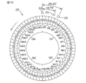
磁石2は、8つの磁極対M1〜M8を有している。つまり、磁石2は、等角度間隔で配置された16個の磁極m1〜m16を有している。各磁極m1〜m16は、ロータ1の回転中心軸を中心として、22.5°(電気角では180°)の角度間隔で配置されている。
この実施形態では、磁極対における磁力の大きさの種類には、磁力が大きい第1の磁力と第1の磁力より磁力が小さい第2の磁力との2種類がある。この実施形態では、8個の磁極対M1〜M8のうち、第1、第2、第3および第5のM1,M2,M3,M5の磁力が第2の磁力(弱い磁力)に設定され、第4、第6、第7および第8の磁極対M4,M6,M7,M8の磁力が第1の磁力(強い磁力)に設定されている。
The
In this embodiment, there are two types of magnitude of the magnetic force in the magnetic pole pair: a first magnetic force having a large magnetic force and a second magnetic force having a smaller magnetic force than the first magnetic force. In this embodiment, among the eight magnetic pole pairs M1 to M8, the magnetic forces of the first, second, third, and fifth M1, M2, M3, and M5 are set to the second magnetic force (weak magnetic force), The magnetic forces of the fourth, sixth, seventh, and eighth magnetic pole pairs M4, M6, M7, and M8 are set to the first magnetic force (strong magnetic force).
ロータ1の周囲には、3つの磁気センサ21,22,23が配置されている。これら3つの磁気センサ21,22,23を、それぞれ第1の磁気センサ21、第2の磁気センサ22および第3の磁気センサ23という場合がある。図2おいて、第2の磁気センサ22は、第1の磁気センサ21に対して、ロータ1の回転中心軸を中心として、時計方向に75°(電気角では600°)だけ離れた位置に配置されている。第3の磁気センサ23は、第1の磁気センサ21に対して、ロータ1の回転中心軸を中心として、時計方向に105°(電気角では840°)だけ離れた位置に配置されている。
Around the
言い換えると、第1の磁気センサ21が第1の磁極対M1における電気角で0°の位置に対向しているときには、第2の磁気センサ22が第2の磁極対M2における電気角で240°の位置に対向し、第3の磁気センサ23が第3の磁極対M3における電気角で120°の位置に対向するように、3つの磁気センサ21,22,23が配置されている。磁気センサとしては、たとえば、ホール素子、磁気抵抗素子(MR素子)等、磁界の作用により電気的特性が変化する特性を有する素子を備えたものを用いることができる。
In other words, when the first
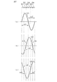
図2に矢印で示す方向をロータ1の正方向の回転方向とする。そして、ロータ1が正方向に回転されるとロータ1の回転角が大きくなり、ロータ1が逆方向に回転されると、ロータ1の回転角が小さくなるものとする。各磁気センサ21,22,23からは、図3に示すように、ロータ1が1磁極対分に相当する角度(45°(電気角では360°))を回転する期間を一周期とする正弦波信号V1,V2,V3が出力される。
A direction indicated by an arrow in FIG. 2 is a positive rotation direction of the
図3は、ロータ1における磁極対M8と磁極対M1との境界が第1の磁気センサ21に対向している場合のロータ1の回転角を0°にとった場合のロータ角度(機械角)に対する、各磁気センサ21,22,23の出力信号V1,V2,V3を示している。また、図3には、ロータ角度に対応して、第1の磁気センサ21が感知している磁極対M1〜M8および磁極m1〜m16が示されているとともに、各磁極対M1〜M8の磁力の大きさが示されている。
FIG. 3 shows a rotor angle (mechanical angle) when the rotation angle of the
ロータ1の1回転分の角度範囲を、8つの磁極対M1〜M8に対応して8つの区間に分け、各区間の開始位置を0°とし終了位置を360°として表したロータ1の角度を、ロータ1の電気角θeということにする。
ここでは、第1の磁気センサ21からは、8つの磁極対M1〜M8に対応する区間毎に、V1=A1・sinθeの出力信号が出力されるものとする。この場合、第2の磁気センサ22からは、8つの磁極対M1〜M8に対応する区間毎に、V2=A2・sin(θe+600°)=A2・sin(θe+240°)の出力信号が出力される。また、第3の磁気センサ23からは、8つの磁極対M1〜M8に対応する区間毎に、V3=A3・sin(θe+840°)=A3・sin(θe+120°)の出力信号が出力される。A1,A2,A3は、それぞれ振幅を表している。ただし、振幅A1,A2,A3は、各磁極対M1〜M8の磁力の大きさに応じて変化する。
The angle range of one rotation of the
Here, it is assumed that an output signal of V1 = A1 · sin θe is output from the first
したがって、各磁気センサ21,22,23からは、互いに所定の位相差120°(電気角)を有する正弦波信号が出力される。各磁気センサ21,22,23の出力信号V1,V2,V3を、それぞれ第1の出力信号V1,第2の出力信号V2および第3の出力信号V3という場合がある。
図1に戻り、各磁気センサ21,22,23の出力信号V1,V2,V3は、回転角演算装置20に入力される。回転角演算装置20は、各磁気センサ21,22,23の出力信号V1,V2,V3に基づいて、各磁気センサ21,22,23が感知している磁極を特定する。各磁気センサ21,22,23が感知している磁極の特定結果に基づいて、回転角演算装置20は、各磁気センサ21,22,23の出力信号V1,V2,V3の振幅を補正する。そして、回転角演算装置20は、振幅補正後の各出力信号に基づいて、ロータ1の電気角θeおよび機械角θmを演算する。
Therefore, each
Returning to FIG. 1, the output signals V <b> 1, V <b> 2, V <b> 3 of the
回転角演算装置20によって演算された電気角θeおよび機械角θmは、モータコントローラ30に与えられる。モータコントローラ30は、回転角演算装置20から与えられる電気角θeおよび機械角θmを用いて、ブラシレスモータ10を制御する。
回転角演算装置20は、たとえば、マイクロコンピュータから構成され、CPU(中央演算処理装置)およびメモリ(ROM,RAM,書き換え可能な不揮発性メモリ等)を含んでいる。回転角演算装置20の不揮発性メモリには、磁気センサ21,22,23毎に、ピーク値テーブルが記憶されている。
The electrical angle θe and the mechanical angle θm calculated by the rotation
The rotation
図4は、ピーク値テーブルの内容を示す模式図である。
ピーク値テーブルには、各磁極m1〜m16の磁極番号1〜16毎に、その磁極に対応する第1の磁気センサ21の出力信号V1のピーク値(極大値または極小値)P1(1)〜P1(16)と、その磁極に対応する第2の磁気センサ22の出力信号V2のピーク値(極大値または極小値)P2(1)〜P2(16)と、その磁極に対応する第3の磁気センサ23の出力信号V3のピーク値(極大値または極小値)P3(1)〜P3(16)とが記憶されている。なお、各磁気センサ21,22,23としては、特性がほぼ等しいものが用いられているので、同じ磁極に対する各磁気センサ21,22,23のピーク値はほぼ同様な値となる。
FIG. 4 is a schematic diagram showing the contents of the peak value table.
In the peak value table, for each of the
前記ピーク値テーブルへのピーク値の記憶は、たとえば、ブラシレスモータ10の出荷前に行われる。前記振幅補正用ピーク値テーブルに記憶されるピーク値は、1周期分のデータから求めてもよいし、複数周期分のデータの平均値から求めてもよい。
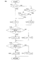
図5は、回転角演算装置20による回転角演算処理の手順を示すフローチャートである。
For example, the peak value is stored in the peak value table before the
FIG. 5 is a flowchart showing a procedure of rotation angle calculation processing by the rotation
図5に示される回転角演算処理は、所定の演算周期毎に繰り返し行なわれる。
回転角演算処理開始時において第1の磁気センサ21が感知している磁極を基準磁極として、各磁極に相対的な番号を割り当てた場合の各磁極の番号を相対的極番号と定義する。第1の磁気センサ21が感知している磁極の相対的極番号(以下、「第1の相対的極番号」という)を変数r1で表し、第2の磁気センサ22が感知している磁極の相対的極番号(以下、「第2の相対的極番号」という)を変数r2で表し、第3の磁気センサ23が感知している磁極の相対的極番号(以下、「第3の相対的極番号」という)を変数r3で表すことにする。なお、各相対的極番号r1,r2,r3は、1〜16の整数をとり、1より1少ない相対的極番号は16となり、16より1大きい相対的極番号は1となるものとする。
The rotation angle calculation process shown in FIG. 5 is repeatedly performed every predetermined calculation cycle.
Using the magnetic pole sensed by the first
この実施形態では、回転角演算処理開始時において第1の磁気センサ21が感知している磁極(基準磁極)がN極の磁極である場合には、当該磁極に”1”の相対的極番号が割り当てられる。一方、回転角演算処理の開始時において第1の磁気センサ21が感知している磁極(基準磁極)がS極の磁極である場合には、当該磁極に”2”の相対的極番号が割り当てられる。
In this embodiment, when the magnetic pole (reference magnetic pole) sensed by the first
また、第1の磁気センサ21が感知している磁極の極番号をq1、第2の磁気センサ22が感知している磁極の極番号をq2、第3の磁気センサ23が感知している磁極の極番号をq3で表すことにする。なお、各極番号q1,q2,q3は、1〜16の整数をとり、1より1少ない極番号は16となり、16より1大きい極番号は1となるものとする。
また、第1の磁気センサ21が感知している磁極対の磁極対番号をQ1で表すことにする。なお、磁極対番号Q1は、1〜8の整数をとり、1より1少ない極番号は8となり、8より1大きい極番号は1となるものとする。
The pole number of the magnetic pole sensed by the first
The magnetic pole pair number sensed by the first
回転角演算処理が開始されると、回転角演算装置20は、各磁気センサ21,22,23の出力信号(センサ値)V1,V2,V3を読み込む(ステップS1)。なお、回転角演算装置20のメモリ(たとえば、RAM)には、所定回数前に読み込まれたセンサ値から最新に読み込まれたセンサ値までの、複数回数分のセンサ値が記憶されるようになっている。
When the rotation angle calculation process is started, the rotation
また、この実施形態では、センサ値V1のピーク値(極大値および極小値)を検出するために、読み込まれたセンサ値V1のうち絶対値がより大きいセンサ値が、センサ値V1のピーク値候補としてメモリに保存される。同様に、センサ値V2のピーク値(極大値および極小値)を検出するために、読み込まれたセンサ値V2のうち絶対値がより大きいセンサ値が、センサ値V2のピーク値候補としてメモリに保存される。同様に、センサ値V3のピーク値(極大値および極小値)を検出するために、読み込まれたセンサ値V3のうち絶対値がより大きいセンサ値が、センサ値V3のピーク値候補としてメモリに保存される。ただし、これらのピーク値候補は、対応する出力信号のゼロクロスが検出されたときには、後述するような所定のタイミングでゼロにリセットされる。 In this embodiment, in order to detect the peak value (maximum value and minimum value) of the sensor value V1, a sensor value having a larger absolute value among the read sensor values V1 is a peak value candidate of the sensor value V1. Is stored in memory. Similarly, in order to detect the peak value (maximum value and minimum value) of the sensor value V2, a sensor value having a larger absolute value among the read sensor values V2 is stored in the memory as a peak value candidate of the sensor value V2. Is done. Similarly, in order to detect the peak value (maximum value and minimum value) of the sensor value V3, a sensor value having a larger absolute value among the read sensor values V3 is stored in the memory as a peak value candidate of the sensor value V3. Is done. However, these peak value candidates are reset to zero at a predetermined timing as will be described later when a zero cross of the corresponding output signal is detected.
前記ステップS1で各センサ値V1,V2,V3が読み込まれると、回転角演算装置20は、今回の処理が回転角演算処理開始後の初回の処理であるか否かを判別する(ステップS2)。今回の処理が回転角演算処理開始後の初回の処理である場合には(ステップS2:YES)、回転角演算装置20は、相対的極番号の設定処理を行う(ステップS3)。
When the sensor values V1, V2, and V3 are read in step S1, the rotation
図6は、相対的極番号の設定処理の詳細な手順を示している。
回転角演算装置20は、まず、第1の出力信号V1が0より大きいか否かを判別する(ステップS21)。第1の出力信号V1が0より大きい場合には(ステップS21:YES)、回転角演算装置20は、第1の磁気センサ21が感知している磁極(基準磁極)がN極の磁極であると判別し、第1の相対的極番号r1を1に設定する(ステップS24)。そして、ステップS26に進む。
FIG. 6 shows the detailed procedure of the relative pole number setting process.
First, the rotation
一方、第1の出力信号V1が0以下である場合には(ステップS21:NO)、回転角演算装置20は、第1の出力信号V1が0より小さいか否かを判別する(ステップS22)。第1の出力信号V1が0より小さい場合には(ステップS22:YES)、第1の磁気センサ21が感知している磁極(基準磁極)がS極の磁極であると判別し、第1の相対的極番号r1を2に設定する(ステップS25)。そして、ステップS26に進む。
On the other hand, when the first output signal V1 is 0 or less (step S21: NO), the rotation
前記ステップS22において、第1の出力信号V1が0以上であると判別された場合には(ステップS22:NO)、つまり、第1の出力信号V1が0である場合には、回転角演算装置20は、ロータ回転角(電気角)が0°であるか180°であるかを判別するために、第3の出力信号V3が0より大きいか否かを判別する(ステップS23)。第3の出力信号V3が0より大きい場合には(ステップS23:YES)、回転角演算装置20は、ロータ回転角(電気角)が0°であると判別し、第1の相対的極番号r1を1に設定する(ステップS24)。そして、ステップS26に進む。
If it is determined in step S22 that the first output signal V1 is equal to or greater than 0 (step S22: NO), that is, if the first output signal V1 is 0, the rotation angle calculation device. 20 determines whether or not the third output signal V3 is greater than 0 in order to determine whether the rotor rotation angle (electrical angle) is 0 ° or 180 ° (step S23). If the third output signal V3 is greater than 0 (step S23: YES), the rotation
一方、第3の出力信号V3が0以下である場合には(ステップS23:NO)、回転角演算装置20は、ロータ回転角(電気角)が180°であると判別し、第1の相対的極番号r1を2に設定する(ステップS25)。そして、ステップS26に進む。
なお、前記ステップS23において、回転角演算装置20は、第2の出力信号V2が0より小さいか否かを判別するようにしてもよい。この場合には、第2の出力信号V2が0より小さいときには、回転角演算装置20は、ステップS24に進んで第1の相対的極番号r1を1に設定する。一方、第2の出力信号V2が0以上である場合には、回転角演算装置20は、ステップS25に進んで第1の相対的極番号r1を2に設定する。
On the other hand, when the third output signal V3 is 0 or less (step S23: NO), the rotation
In step S23, the rotation
ステップS26では、回転角演算装置20は、「V1≧0かつV2<0」または「V1≦0かつV2>0」の条件を満たしているか否かを判別する。この条件を満たしている場合には(ステップS26:YES)、回転角演算装置20は、第2の磁気センサ22が感知している磁極の極番号は、第1の磁気センサ21が感知している磁極の極番号より3だけ大きい番号であると判別し、第2の相対的極番号r2に、第1の相対的極番号r1より3だけ大きい番号(r2=r1+3)を設定する(ステップS27)。そして、ステップS29に移行する。
In step S26, the rotation
一方、前記ステップS26の条件を満たしていない場合には(ステップS26:NO)、回転角演算装置20は、第2の磁気センサ22が感知している磁極の極番号は、第1の磁気センサ21が感知している磁極の極番号より4だけ大きい番号であると判別し、第2の相対的極番号r2に、第1の相対的極番号r1より4だけ大きい番号(r2=r1+4)を設定する(ステップS28)。そして、ステップS29に移行する。
On the other hand, when the condition of step S26 is not satisfied (step S26: NO), the rotation
ステップS29では、回転角演算装置20は、「V1>0かつV3≦0」または「V1<0かつV3≧0」の条件を満たしているか否かを判別する。この条件を満たしている場合には(ステップS29:YES)、回転角演算装置20は、第3の磁気センサ23が感知している磁極の極番号は、第1の磁気センサ21が感知している磁極の極番号より5だけ大きい番号であると判別し、第3の相対的極番号r3に、第1の相対的極番号r1より5だけ大きい番号(r3=r1+5)を設定する(ステップS30)。そして、図5のステップS12に戻る。
In step S29, the rotation
一方、前記ステップS29の条件を満たしていない場合には(ステップS29:NO)、回転角演算装置20は、第3の磁気センサ23が感知している磁極の極番号は、第1の磁気センサ21が感知している磁極の極番号より4だけ大きい番号であると判別し、第3の相対的極番号r3に、第1の相対的極番号r1より4だけ大きい番号(r3=r1+4)を設定する(ステップS31)。そして、図5のステップS12に戻る。
On the other hand, when the condition of step S29 is not satisfied (step S29: NO), the rotation
前記ステップS26の条件を満たしている場合に、第2の相対的極番号r2に第1の相対的極番号r1より3だけ大きい番号(r2=r1+3)を設定し、前記ステップS26の条件を満たしていない場合に、第2の相対的極番号r2に第1の相対的極番号r1より4だけ大きい番号(r2=r1+4)を設定している理由について説明する。また、前記ステップS29の条件を満たしている場合に、第3の相対的極番号r3に、第1の相対的極番号r1より5だけ大きい番号(r3=r1+5)を設定し、前記ステップS29の条件を満たしていない場合に、第3の相対的極番号r3に、第1の相対的極番号r1より4だけ多い番号(r3=r1+4)を設定している理由について説明する。 When the condition of step S26 is satisfied, a number (r2 = r1 + 3) that is 3 larger than the first relative pole number r1 is set to the second relative pole number r2, and the condition of step S26 is satisfied. The reason why the number (r2 = r1 + 4) larger by 4 than the first relative pole number r1 is set in the second relative pole number r2 in the case where the second relative pole number r2 is not set will be described. If the condition of step S29 is satisfied, a number (r3 = r1 + 5) larger than the first relative pole number r1 by 5 (r3 = r1 + 5) is set as the third relative pole number r3. The reason why the number (r3 = r1 + 4) which is 4 more than the first relative pole number r1 is set as the third relative pole number r3 when the condition is not satisfied will be described.
たとえば、ロータ1における磁極m1と磁極m2とからなる磁極対M1が第1の磁気センサ21を通過する際の、第1、第2および第3の磁気センサ21,22,23の出力信号V1,V2,V3の信号波形を模式的に表すと、図7(a)(b)(c)に示すようになる。
図7(a)(b)において、S1,S2で示す領域は、第1の磁気センサ21が磁極m1を感知し、第2の磁気センサ22が磁極m4を感知している領域である。S3で示す領域は、第1の磁気センサ21が磁極m1を感知し、第2の磁気センサ22が磁極m5を感知している領域である。S4,S5で示す領域は、第1の磁気センサ21が磁極m2を感知し、第2の磁気センサ22が磁極m5を感知している領域である。S6で示す領域は、第1の磁気センサ21が磁極m2を感知し、第2の磁気センサ22が磁極m6を感知している領域である。
For example, when the magnetic pole pair M <b> 1 composed of the magnetic pole m <b> 1 and the magnetic pole m <b> 2 in the
7A and 7B, areas indicated by S1 and S2 are areas where the first
つまり、領域S1,S2,S4およびS5では、第2の磁気センサ22が感知している磁極の極番号は、第1の磁気センサ21が感知している磁極の極番号より3だけ大きくなる。一方、領域S3およびS6では、第2の磁気センサ22が感知している磁極の極番号は、第1の磁気センサ21が感知している磁極の極番号より4だけ大きい番号となる。
領域S1,S2においては、両センサ値V1,V2は、V1≧0かつV2<0の第1条件を満たす。領域S3においては、両センサ値V1,V2は、V1>0かつV2≧0の第2条件を満たす。領域S4,S5においては、両センサ値V1,V2は、V1≦0かつV2>0の第3条件を満たす。領域S6においては、両センサ値V1,V2は、V1<0かつV2≦0の第4条件を満たす。
In other words, in the regions S1, S2, S4, and S5, the pole number of the magnetic pole sensed by the second
In the regions S1 and S2, the sensor values V1 and V2 satisfy the first condition of V1 ≧ 0 and V2 <0. In the region S3, both sensor values V1 and V2 satisfy the second condition of V1> 0 and V2 ≧ 0. In the regions S4 and S5, the sensor values V1 and V2 satisfy the third condition of V1 ≦ 0 and V2> 0. In the region S6, both sensor values V1 and V2 satisfy the fourth condition of V1 <0 and V2 ≦ 0.
そこで、回転角演算装置20は、前記第1条件(V1≧0かつV2<0)または前記第3条件(V1≦0かつV2>0)を満たしている場合には、第2の磁気センサ22が感知している磁極の極番号は、第1の磁気センサ21が感知している磁極の極番号より3だけ大きくなると判別し、前記第1条件または前記第3条件を満たしていない場合には、第2の磁気センサ22が感知している磁極の極番号は、第1の磁気センサ21が感知している磁極の極番号より4だけ大きくなると判別している。
Therefore, when the rotation
また、図7(a)(c)において、S1で示す領域は、第1の磁気センサ21が磁極m1を感知し、第3の磁気センサ23が磁極m5を感知している領域である。S2およびS3で示す領域は、第1の磁気センサ21が磁極m1を感知し、第3の磁気センサ23が磁極M6を感知している領域である。S4で示す領域は、第1の磁気センサ21が磁極m2を感知し、第3の磁気センサ23が磁極M6を感知している領域である。S5およびS6で示す領域は、第1の磁気センサ21が磁極m2を感知し、第3の磁気センサ23が磁極m7を感知している領域である。
7A and 7C, the region indicated by S1 is a region where the first
つまり、領域S1およびS4では、第3の磁気センサ23が感知している磁極の極番号は、第1の磁気センサ21が感知している磁極の極番号より4だけ大きい番号となる。一方、領域S2,S3,S5およびS6では、第2の磁気センサ22が感知している磁極の極番号は、第1の磁気センサ21が感知している磁極の極番号より5だけ大きくなる。
領域S1においては、両センサ値V1,V3は、V1≧0かつV3>0の第1条件を満たす。領域S2,S3においては、両センサ値V1,V3は、V1>0かつV3≦0の第2条件を満たす。領域S4においては、両センサ値V1,V3は、V1≦0かつV3<0の第3条件を満たす。領域S5,S6においては、両センサ値V1,V3は、V1<0かつV3≧0の第4条件を満たす。
That is, in the regions S1 and S4, the pole number of the magnetic pole sensed by the third
In the region S1, both sensor values V1 and V3 satisfy the first condition of V1 ≧ 0 and V3> 0. In the regions S2 and S3, the sensor values V1 and V3 satisfy the second condition of V1> 0 and V3 ≦ 0. In the region S4, both sensor values V1 and V3 satisfy the third condition of V1 ≦ 0 and V3 <0. In the regions S5 and S6, the sensor values V1 and V3 satisfy the fourth condition of V1 <0 and V3 ≧ 0.
そこで、回転角演算装置20は、前記第2条件(V1>0かつV3≦0)または前記第4条件(V1<0かつV3≧0)を満たしている場合には、第3の磁気センサ23が感知している磁極の極番号は、第1の磁気センサ21が感知している磁極の極番号より5だけ大きくなると判別し、前記第2条件または前記第4条件を満たしていない場合には、第3の磁気センサ23が感知している磁極の極番号は、第1の磁気センサ21が感知している磁極の極番号より4だけ大きくなると判別している。
Therefore, when the rotation
図5に戻り、前記ステップS2において、今回の処理が回転角演算処理開始後の初回の処理ではないと判別された場合には(ステップS2:NO)、ステップS4に移行する。
ステップS4では、回転角演算装置20は、メモリに記憶されているセンサ値V1,V2,V3に基づいて、センサ値V1,V2,V3毎に、センサ値の符号が反転するゼロクロスを検出したか否かを判別する。ゼロクロスが検出されなかったときには(ステップS4:NO)、回転角演算装置20は、ステップS12に移行する。
Returning to FIG. 5, if it is determined in step S2 that the current process is not the first process after the start of the rotation angle calculation process (step S2: NO), the process proceeds to step S4.
In step S4, whether the rotation
前記ステップS4において、いずれかのセンサ値V1,V2,V3に対してゼロクロスが検出された場合には(ステップS4:YES)、回転角演算装置20は、後述するステップS10の極番号特定処理によって、各磁極センサ21,22,23が検知している磁極が既に特定されているか否かを判別する(ステップS5)。
各磁極センサ21,22,23が検知している磁極が特定されていない場合には、回転角演算装置20は、相対的極番号の更新処理を行なう(ステップS6)。具体的には、回転角演算装置20は、前記ステップS4でゼロクロスが検出された磁気センサに対して現在設定されている相対的極番号r1、r2またはr3を、ロータ1の回転方向に応じて、1だけ大きい番号または1だけ小さい番号に変更する。
If a zero cross is detected for any one of the sensor values V1, V2, and V3 in step S4 (step S4: YES), the rotation
When the magnetic pole detected by each of the
ロータ1の回転方向が正方向(図2に矢印で示す方向)である場合には、回転角演算装置20は、前記ステップS4でゼロクロスが検出された磁気センサに対して現在設定されている相対的極番号r1、r2またはr3を、1だけ大きい番号に更新する。一方、ロータ1の回転方向が逆方向である場合には、回転角演算装置20は、ゼロクロスが検出された磁気センサに対して現在設定されている相対的極番号r1、r2またはr3を、1だけ小さい番号に更新する。ただし、前述したように、”1”の相対的極番号に対して、1だけ小さい相対的極番号は、”16”となる。また、”16”の相対的極番号に対して、1だけ大きい相対的極番号は、”1”となる。
When the rotation direction of the
なお、ロータ1の回転方向は、ゼロクロスが検出された出力信号の前回値および今回値と、他の1つの出力信号の今回値とに基づいて判定することができる。具体的には、ゼロクロスが検出された出力信号が第1の出力信号V1である場合には、「第1の出力信号V1の前回値が0より大きくかつその今回値が0以下であり、第3の出力信号V3が0より小さい(または第2の出力信号V2が0より大きい)」という条件、または「第1の出力信号V1の前回値が0未満でかつその今回値が0以上であり、第3の出力信号V3が0より大きい(または第2の出力信号V2が0より小さい)」という条件を満たしている場合には、回転方向は正方向(図2に矢印で示す方向)であると判定される。
Note that the rotation direction of the
一方、「第1の出力信号V1の前回値が0以上でかつその今回値が0未満であり、第3の出力信号V3が0より大きい(または第2の出力信号V2が0より小さい)」という条件、または「第1の出力信号V1の前回値が0以下でかつその今回値が0より大きく、第3の出力信号V3が0より小さい(または第2の出力信号V2が0より大きい)」という条件を満たしている場合には、回転方向は逆方向であると判定される。 On the other hand, “the previous value of the first output signal V1 is 0 or more and the current value is less than 0, and the third output signal V3 is greater than 0 (or the second output signal V2 is less than 0)” Or “the previous value of the first output signal V1 is 0 or less and the current value is greater than 0 and the third output signal V3 is less than 0 (or the second output signal V2 is greater than 0). Is satisfied, the rotation direction is determined to be the reverse direction.
ゼロクロスが検出された出力信号が第2の出力信号V2である場合には、「第2の出力信号V2の前回値が0より大きくかつその今回値が0以下であり、第1の出力信号V1が0より小さい(または第3の出力信号V3が0より大きい)」という条件、または「第2の出力信号V2の前回値が0未満でかつその今回値が0以上であり、第1の出力信号V1が0より大きい(または第3の出力信号V3が0より小さい)」という条件を満たしている場合には、回転方向は正方向(図2に矢印で示す方向)であると判定される。一方、「第2の出力信号V2の前回値が0以上でかつその今回値が0未満であり、第1の出力信号V1が0より大きい(または第3の出力信号V3が0より小さい)」という条件、または「第2の出力信号V2の前回値が0以下でかつその今回値が0より大きく、第1の出力信号V1が0より小さい(または第3の出力信号V3が0より大きい)」という条件を満たしている場合には、回転方向は逆方向であると判定される。 When the output signal in which the zero cross is detected is the second output signal V2, “the previous value of the second output signal V2 is greater than 0 and the current value is less than or equal to 0, and the first output signal V1 Is less than 0 (or the third output signal V3 is greater than 0), or “the previous value of the second output signal V2 is less than 0 and its current value is greater than or equal to 0, and the first output When the condition that the signal V1 is greater than 0 (or the third output signal V3 is less than 0) is satisfied, the rotation direction is determined to be the positive direction (the direction indicated by the arrow in FIG. 2). . On the other hand, “the previous value of the second output signal V2 is 0 or more and the current value is less than 0, and the first output signal V1 is greater than 0 (or the third output signal V3 is less than 0)” Or “the previous value of the second output signal V2 is 0 or less and the current value is greater than 0 and the first output signal V1 is less than 0 (or the third output signal V3 is greater than 0). Is satisfied, the rotation direction is determined to be the reverse direction.
ゼロクロスが検出された出力信号が第3の出力信号V3である場合には、「第3の出力信号V3の前回値が0より大きくかつその今回値が0以下であり、第1の出力信号V1が0より大きい(または第2の出力信号V2が0より小さい)」という条件、または「第3の出力信号V3の前回値が0未満でかつその今回値が0以上であり、第1の出力信号V1が0より小さい(または第2の出力信号V2が0より大きい)」という条件を満たしている場合には、回転方向は正方向(図2に矢印で示す方向)であると判定される。一方、「第3の出力信号V3の前回値が0以上でかつその今回値が0未満であり、第1の出力信号V1が0より小さい(または第2の出力信号V2が0より大きい)」という条件、または「第3の出力信号V3の前回値が0以下でかつその今回値が0より大きく、第1の出力信号V1が0より大きい(または第2の出力信号V2が0より小さい)」という条件を満たしている場合には、回転方向は逆方向であると判定される。 When the output signal in which the zero cross is detected is the third output signal V3, “the previous value of the third output signal V3 is larger than 0 and its current value is 0 or less, and the first output signal V1. Is greater than 0 (or the second output signal V2 is less than 0), or “the previous value of the third output signal V3 is less than 0 and its current value is greater than or equal to 0, and the first output When the condition that the signal V1 is smaller than 0 (or the second output signal V2 is larger than 0) is satisfied, the rotation direction is determined to be the positive direction (the direction indicated by the arrow in FIG. 2). . On the other hand, “the previous value of the third output signal V3 is 0 or more and the current value is less than 0, and the first output signal V1 is less than 0 (or the second output signal V2 is greater than 0)” Or “the previous value of the third output signal V3 is 0 or less and the current value is greater than 0 and the first output signal V1 is greater than 0 (or the second output signal V2 is less than 0). Is satisfied, the rotation direction is determined to be the reverse direction.
前記ステップS6の相対的極番号の更新処理が終了すると、回転角演算装置20は、ピーク値検出処理を行なう(ステップS7)。ピーク値検出処理について具体的に説明する。前記ステップS4でゼロクロスが検出された出力信号に対応する磁気センサをピーク値検出対象の磁気センサということにする。回転角演算装置20は、まず、ピーク値検出対象の磁気センサが感知している磁極が変化したか否かを判別する。つまり、回転角演算装置20は、ピーク値検出対象の磁気センサが感知している磁極位置が、当該磁気センサの出力信号のゼロクロスが前回検出された時点と、今回検出された時点とで、異なっているか同じであるかを判定する。ロータ1の回転方向が逆転した場合には、前記両時点での磁極位置が同じになる可能性がある。
When the update process of the relative pole number in step S6 is completed, the rotation
この判定は、たとえば、前回ゼロクロスが検出されたときのロータ1の回転方向と、現在のロータ1の回転方向が同じ方向であるか否かに基づいて行うことができる。すなわち、回転角演算装置20は、ロータ1の回転方向が同じ方向であれば、ピーク値検出対象の磁気センサが感知している磁極が変化したと判定する。一方、ロータ1の回転方向が異なっていれば、回転角演算装置20は、ピーク値検出対象の磁気センサが感知している磁極が変化していないと判定する。
This determination can be made, for example, based on whether or not the rotation direction of the
ピーク値検出対象の磁気センサが感知している磁極が変化したと判定された場合には、回転角演算装置20は、ピーク値を検出したと判別するとともに、当該磁気センサに対応するピーク値候補をピーク値として特定する。一方、ピーク値検出対象の磁気センサが感知している磁極が変化していないと判定された場合には、回転角演算装置20は、ピーク値を検出しなかったと判定する。なお、ピーク値には、0より大きな極大値と、0より小さな極小値とがある。この実施形態では、ピーク値のうち、極大値に基づいて、第1の磁気センサ21が感知している磁極対が特定されるものとする。以下において、ピーク値検出処理において検出された第1の出力信号V1、第2の出力信号V2および第3の出力信号V3の極大値を、それぞれP1、P2およびP3で表す場合がある。
When it is determined that the magnetic pole sensed by the magnetic sensor targeted for peak value detection has changed, the rotation
ピーク値検出処理において極大値が検出されなかった場合には(ステップS8:NO)、回転角演算装置20は、前記ステップS4でゼロクロスが検出された出力信号に対応するピーク値候補を0にリセットした後、ステップS12に移行する。一方、ピーク値検出処理において極大値が検出されたときには(ステップS8:YES)、当該極大値を、前記ステップS4でゼロクロスが検出された出力信号に対する極大値P1、P2またはP3として記憶する(ステップS9)。そして、回転角演算装置20は、前記ステップS4でゼロクロスが検出された出力信号に対応するピーク値候補を0にリセットした後、ステップS10に移行する。
When the maximum value is not detected in the peak value detection process (step S8: NO), the rotation
ステップS10では、回転角演算装置20は、極番号特定処理(磁極対特定処理)を行なう。
図3を参照して、極番号特定処理の考え方について説明する。図3に示すように、磁力が弱い磁極対M1,M2,M3,M5内のN磁極m1,m3,m5,m9に対する各出力信号V1,V2,V3のピーク値(極大値)と、磁力が強い磁極対M4,M6,M7,M8内のN磁極m7,m11,m13,m15に対する各出力信号V1,V2,V3のピーク値(極大値)との中間に、閾値A(A>0)が設定されている。
In step S10, the rotation
The concept of the pole number identification process will be described with reference to FIG. As shown in FIG. 3, the peak values (maximum values) of the output signals V1, V2, and V3 for the N magnetic poles m1, m3, m5, and m9 in the magnetic pole pairs M1, M2, M3, and M5 having a weak magnetic force, and the magnetic force A threshold A (A> 0) is intermediate between the peak values (maximum values) of the output signals V1, V2, and V3 for the N magnetic poles m7, m11, m13, and m15 in the strong magnetic pole pairs M4, M6, M7, and M8. Is set.
図3から分かるように、第1の磁気センサ21が感知している磁極対M1〜M8毎に、3つの出力信号V1,V2,V3の極大値の組合せが異なっている。したがって、3つの出力信号V1,V2,V3の極大値P1,P2,P3の組合せに基づいて、第1の磁気センサ21が感知している磁極対を特定することができる。また、第1の磁気センサ21が感知している磁極対を特定するタイミングに基づいて、第1の磁気センサ21が感知している磁極を特定することができる。そして、第1の磁気センサ21が感知している磁極に基づいて、第2および第3の磁気センサ22,23が感知している磁極を特定することができる。
As can be seen from FIG. 3, the combinations of the maximum values of the three output signals V1, V2, and V3 are different for each of the magnetic pole pairs M1 to M8 sensed by the first
第1の磁気センサ21が感知している磁極対M1〜M8と、3つの出力信号V1,V2,V3の極大値P1,P2,P3の組合せとの関係は、表1に示すようになる。
Table 1 shows the relationship between the magnetic pole pairs M1 to M8 sensed by the first

なお、第1の磁気センサ21が感知している磁極対を特定するタイミングは、ロータ1が正方向に回転している場合には、第1の磁気センサ21が感知している磁極対が移り変わった後に、第3の出力信号V3のゼロクロスが初めて検出されるタイミング(以下、「第1の磁極対特定タイミング」という)である。したがって、第1の磁極対特定タイミングにおいて表1の内容に基づいて特定される磁極対は、第1の磁気センサ21が直前まで感知していた磁極対となる。このため、第1の磁極対特定タイミングにおいて第1の磁気センサ21が感知している磁極対は、表1の内容に基づいて特定される磁極対より磁極対番号が1だけ大きい磁極対となる。また、第1の磁極対特定タイミングにおいて第1の磁気センサ21が感知している磁極は、第1の磁極対特定タイミングにおいて第1の磁気センサ21が感知している磁極対内の2つの磁極のうち、N極の磁極となる。
Note that the timing of specifying the magnetic pole pair sensed by the first
一方、ロータ1が逆方向に回転している場合には、第1の磁気センサ21が感知している磁極対を特定するタイミングは、第1の磁気センサ21が感知している磁極対が移り変わった直後に、第1の出力信号V1のゼロクロスが検出されるタイミング(以下、「第2の磁極対特定タイミング」という)である。したがって、第2の磁極対特定タイミングにおいて表1の内容に基づいて特定される磁極対は、第1の磁気センサ21が直前まで感知していた磁極対となる。このため、第2の磁極対特定タイミングにおいて第1の磁気センサ21が感知している磁極対は、表1の内容に基づいて特定される磁極対より磁極対番号が1だけ小さい磁極対となる。また、第2の磁極対特定タイミングにおいて第2の磁気センサ21が感知している磁極は、第2の磁極対特定タイミングにおいて第1の磁気センサ21が感知している磁極対内の2つの磁極のうち、S極の磁極となる。
On the other hand, when the
以下、より具体的に、極番号特定処理について説明する。極番号特定処理は、3つの出力信号V1,V2,V3の極大値が既に検出(記憶)されている場合において、次の第1条件または第2条件のいずかを満たしている場合にのみ行われる。
第1条件:ロータ1の回転方向が正方向でありかつ前記ステップS4でゼロクロスが検出された出力信号が第3の出力信号V3であること
第2条件:ロータ1の回転方向が逆方向でありかつ前記ステップS4でゼロクロスが検出された出力信号が第1の出力信号V1であること
第1条件は、第1の磁極対特定タイミングであるか否かを判定するための条件である。第1条件を満たしている場合には、現時点が第1の磁極対特定タイミングであると判定される。第2条件は、第2の磁極対特定タイミングであるか否かを判定するための条件である。第2条件を満たしている場合には、現時点が第2の磁極対特定タイミングであると判定される。
Hereinafter, the pole number specifying process will be described more specifically. The pole number specifying process is performed only when the maximum value of the three output signals V1, V2, and V3 has already been detected (stored) and either of the following first condition or second condition is satisfied. Done.
First condition: The rotation direction of the
第1条件を満たしている場合には、回転角演算装置20は、表1に示される磁極対M1〜M8と3つの極大値P1,P2,P3の組合せとの関係と、最新に検出された各出力信号V1,V2,V3の極大値P1.P2,P3の組み合わせとに基づいて、第1の磁気センサ21が直前まで感知していた磁極対の磁極対番号Q1’を特定する。そして、当該磁極対番号Q1’より1だけ大きい磁極対番号を、第1の磁極センサ21が現在感知している磁極対の磁極対番号Q1(=Q1’+1)として特定する。
When the first condition is satisfied, the rotation
次に、回転角演算装置20は、第1の磁極センサ21が現在感知している磁極の極番号q1を、q1=2・Q1−1に基づいて特定する。また、回転角演算装置20は、第1の磁気センサ21が感知している磁極の極番号q1と、第1および第2の相対的極番号r1,r2とに基づいて、第2の磁気センサ22が感知している磁極の極番号q2を特定する。具体的には、回転角演算装置20は、q2=(q1−r1)+r2に基づいて、第2の磁気センサ22が感知している磁極の極番号q2を特定する。
Next, the rotation
さらに、回転角演算装置20は、第1の磁気センサ21が感知している磁極の極番号q1と、第1および第3の相対的極番号r1,r3とに基づいて、第3の磁気センサ23が感知している磁極の極番号q3を特定する。具体的には、回転角演算装置20は、q3=(q1−r1)+r3に基づいて、第3の磁気センサ23が感知している磁極の極番号q3を特定する。そして、ステップS12に移行する。
Further, the rotation
一方、第2条件を満たしている場合には、回転角演算装置20は、表1に示される磁極対M1〜M8と3つの極大値P1,P2,P3の組合せとの関係と、最新に検出された各出力信号V1,V2,V3の極大値P1.P2,P3の組み合わせとに基づいて、第1の磁気センサ21が直前まで感知していた磁極対の磁極対番号Q1’を特定する。そして、当該磁極対番号Q1’より1だけ小さい磁極対番号を、第1の磁極センサ21が現在感知している磁極対の磁極対番号Q1(=Q1’−1)として特定する。
On the other hand, when the second condition is satisfied, the rotation
次に、回転角演算装置20は、第1の磁極センサ21が現在感知している磁極の極番号q1を、q1=2・Q1に基づいて特定する。また、回転角演算装置20は、q2=(q1−r1)+r2に基づいて、第2の磁気センサ22が感知している磁極の極番号q2を特定する。さらに、回転角演算装置20は、q3=(q1−r1)+r3に基づいて、第3の磁気センサ23が感知している磁極の極番号q3を特定する。そして、ステップS12に移行する。
Next, the rotation
なお、前記ステップS10において、3つの出力信号V1,V2,V3の極大値P1,P2,P3が検出(記憶)されていないと判別された場合、あるいは3つの出力信号V1,V2,V3の極大値P1,P2,P3が検出されていても、前記第1条件および第2条件のいずれをも満たしていないと判別された場合には、回転角演算装置20は、前述した極番号特定処理を行なうことなく、ステップS12に移行する。
If it is determined in step S10 that the maximum values P1, P2, P3 of the three output signals V1, V2, V3 are not detected (stored), or the maximum of the three output signals V1, V2, V3. If it is determined that neither the first condition nor the second condition is satisfied even if the values P1, P2, P3 are detected, the rotation
前記ステップS5において、各磁気センサ21,22,23が感知している磁極が既に特定されていると判別された場合には(ステップS5:YES)、回転角演算装置20は、前記ステップS4でゼロクロスが検出された出力信号に対応するピーク値候補を0にリセットした後、極番号の更新処理を行なう(ステップS11)。具体的には、回転角演算装置20は、前記ステップS4でゼロクロスが検出された磁気センサに対して既に特定されている極番号q1、q2またはq3を、ロータ1の回転方向に応じて、1だけ大きい極番号または1だけ小さい極番号に変更する。
If it is determined in step S5 that the magnetic poles detected by the
ロータ1の回転方向が正方向である場合には、回転角演算装置20は、ゼロクロスが検出された磁気センサに対して既に特定されている前記極番号q1、q2またはq3を、1だけ大きい極番号に更新する。一方、ロータ1の回転方向が逆方向である場合には、回転角演算装置20は、ゼロクロスが検出された磁気センサに対して既に特定されている前記極番号q1、q2またはq3を、1だけ小さい極番号に更新する。ただし、”1”の極番号に対して、1だけ小さい極番号は、”16”となる。また、”16”の極番号に対して、1だけ大きい極番号は、”1となる。回転角演算装置20は、ステップS11の極番号の更新処理が終了すると、ステップS12に移行する。
When the rotation direction of the
ステップS12では、回転角演算装置20は、振幅補正処理を行う。つまり、回転角演算装置20は、各磁気センサ21,22,23が感知している磁極の極番号q1,q2,q3が特定されている場合には、各磁気センサ21,22,23の出力信号V1,V2,V3の振幅を補正する。一方、各磁気センサ21,22,23が感知している磁極の極番号q1,q2,q3が特定されていない場合には、回転角演算装置20は、振幅補正処理を行うことなく、ステップS13に移行する。
In step S12, the rotation
各磁気センサ21,22,23が感知している磁極の極番号q1,q2,q3が特定されている場合には、回転角演算装置20は、第1の磁気センサ21が感知している磁極の極番号q1に対応する第1の出力信号V1のピーク値と、第2の磁気センサ22が感知している磁極の極番号q2に対応する第2の出力信号V2のピーク値と、第3の磁気センサ23が感知している磁極の極番号q3に対応する第3の出力信号V3のピーク値とを、ピーク値テーブル(図4参照)から取得する。ピーク値テーブルから取得された第1、第2および第3の出力信号V1,V2,V3のピーク値を、それぞれP1x,P2x,P3xで表すことにする。そして、取得した各ピーク値(振幅補正値)P1x,P2x,P3xと予め設定されている基準振幅φとに基づいて、各出力信号V1,V2,V3の振幅を補正する。
When the pole numbers q1, q2, and q3 of the magnetic poles sensed by the
具体的には、第1、第2および第3の出力信号V1,V2,V3の振幅補正後の信号をそれぞれV1’,V2’,V3’とすると、補正後の第1、第2および第3の出力信号V1’,V2’,V3’は、それぞれ次式(2)(3)(4)に基づいて演算される。
V1’=(V1/P1x)×φ …(2)
V2’=(V2/P2x)×φ …(3)
V3’=(V3/P3x)×φ …(4)
振幅補正処理が終了すると、回転角演算装置20は、ステップS13に移行する。ステップS13では、回転角演算装置20は、前記ステップS12で振幅補正された各出力信号V1’,V2’,V3’ に基づいて、電気角θeを演算する。ただし、前記ステップS12で振幅補正が行われなかった場合には、前記ステップS1で読み込まれたセンサ値V1,V2,V3に基づいて、電気角θeを演算する。
Specifically, if the amplitude-corrected signals of the first, second, and third output signals V1, V2, and V3 are V1 ′, V2 ′, and V3 ′, respectively, the corrected first, second, and
V1 ′ = (V1 / P1x) × φ (2)
V2 ′ = (V2 / P2x) × φ (3)
V3 ′ = (V3 / P3x) × φ (4)
When the amplitude correction process ends, the rotation
以下、振幅補正された各出力信号V1’,V2’,V3’ に基づいて、電気角θeを演算する場合について説明する。なお、前記ステップS1で読み込まれたセンサ値V1,V2,V3に基づいて電気角θeを演算する場合には、補正後の各出力信号V1’,V2’,V3’の代わりにセンサ値V1,V2,V3が用いられるだけなので、その説明を省略する。 Hereinafter, a case where the electrical angle θe is calculated based on the output signals V1 ', V2', V3 'whose amplitude has been corrected will be described. When calculating the electrical angle θe based on the sensor values V1, V2, and V3 read in step S1, the sensor values V1, V2 ′, and V3 ′ are used instead of the corrected output signals V1 ′, V2 ′, and V3 ′. Since only V2 and V3 are used, the description thereof is omitted.
回転角演算装置20は、振幅補正後の第1の出力信号V1’と振幅補正後の第3の出力信号V3’とに基づいて、ロータ1の回転角に相当する第1の電気角θe1を演算する。また、回転角演算装置20は、振幅補正後の第1の出力信号V1’と振幅補正後の第2の出力信号V2’とに基づいて、ロータ1の回転角に相当する第2の電気角θe2を演算する。また、回転角演算装置20は、振幅補正後の第2の出力信号V2’と振幅補正後の第3の出力信号V3’とに基づいて、ロータ1の回転角に相当する第3の電気角θe3を演算する。第1、第2および第3の電気角θe1,θe2,θe3の演算方法については、後述する。
The rotation
そして、回転角演算装置20は、たとえば、次式(5)に基づいて、最終的な電気角θeを演算する。つまり、回転角演算装置20は、第1、第2および第3の電気角θe1,θe2,θe3の平均値を、最終的な電気角θeとして演算する。
θe=(θe1+θe2+θe3)/3 …(5)
なお、回転角演算装置20は、第1、第2および第3の電気角θe1,θe2,θe3の中央値を、最終的な電気角θeとして演算することができる。また、回転角演算装置20は、第1、第2および第3の電気角θe1,θe2,θe3のうち、最も外れているものを除外し、他の2つの平均値を、最終的な電気角θeとして演算することもできる。さらに、回転角演算装置20は、第1,第2および第3の電気角θe1,θe2,θe3のいずれか1つの電気角を、最終的な電気角θeとして決定してもよい。
Then, the rotation
θe = (θe1 + θe2 + θe3) / 3 (5)
The rotation
第1の電気角θe1の演算方法について説明する。前記基準振幅はφであるので、振幅補正後の第1の出力信号V1’はφ・sinθeで表され、振幅補正後の第2の出力信号V2’はφ・sin(θe+240°)で表され、振幅補正後の第3の出力信号V3はφ・sin(θe+120°)で表される。ここでは、説明の便宜上、基準振幅φが1であるとし、振幅補正後の第1の出力信号V1’、第2の出力信号V2’および第3の出力信号V3を、それぞれV1’=sinθe、V2’=sin(θe+240°)およびV3=sin(θe+120°)で表すことにする。 A method of calculating the first electrical angle θe1 will be described. Since the reference amplitude is φ, the first output signal V1 ′ after amplitude correction is represented by φ · sin θe, and the second output signal V2 ′ after amplitude correction is represented by φ · sin (θe + 240 °). The third output signal V3 after amplitude correction is represented by φ · sin (θe + 120 °). Here, for convenience of explanation, it is assumed that the reference amplitude φ is 1, and the first output signal V1 ′, the second output signal V2 ′, and the third output signal V3 after amplitude correction are expressed as V1 ′ = sin θe, Let V2 ′ = sin (θe + 240 °) and V3 = sin (θe + 120 °).
回転角演算装置20は、まず、振幅補正後の第1の出力信号V1’(=sinθe)と振幅補正後の第3の出力信号V3’(=sin(θe+120°))とから、振幅補正後の第1の出力信号V1’に対する位相差が90°となる信号V13’(=sin(θe+90°)=cosθe)を演算する。より具体的には、回転角演算装置20は、次式(6)に基づいて、信号V13’を演算する。
The rotation
前記式(6)は、sin(θe+120°)を三角関数の加法定理により展開した式に基づいて、導出することができる。そして、回転角演算装置20は、前記信号V13’(=cosθe)と振幅補正後の第1の出力信号V1’(=sinθe)とを用い、次式(7)に基づいて、第1の電気角θe1を演算する。
The expression (6) can be derived based on an expression obtained by expanding sin (θe + 120 °) by the addition theorem of trigonometric functions. Then, the rotation
第2の電気角θe2の演算方法について説明する。回転角演算装置20は、まず、振幅補正後の第1の出力信号V1’(=sinθe)と振幅補正後の第2の出力信号V2’(=sin(θe+240°))とから、振幅補正後の第1の出力信号V1’に対する位相差が90°となる信号V12’(=sin(θe+90°)=cosθe)を生成する。より具体的には、回転角演算装置20は、次式(8)に基づいて、信号V12’を生成する。
A method of calculating the second electrical angle θe2 will be described. The rotation
前記式(8)は、sin(θe+240°)を三角関数の加法定理により展開した式に基づいて、導出することができる。そして、回転角演算装置20は、前記信号V12’(=cosθe)と振幅補正後の第1の出力信号V1’(=sinθe)とを用い、次式(9)に基づいて、第2の電気角θe2を演算する。
The equation (8) can be derived based on an equation obtained by expanding sin (θe + 240 °) by the addition theorem of trigonometric functions. Then, the rotation
第3の電気角θe3の演算方法について説明する。回転角演算装置20は、まず、振幅補正後の第2の出力信号V2’と振幅補正後の第3の出力信号V3’とに基づいて、ロータ1の回転角(電気角)θeに対して120°だけ進んだ電気角θe3’(=θe+120°)を演算する。そして、得られた回転角θe3’から120°を減算することにより、第3の電気角θe3を演算する。
A method of calculating the third electrical angle θe3 will be described. First, the rotation
回転角演算装置20は、振幅補正後の第3の出力信号V3’(=sin(θe+120°))と振幅補正後の第2の出力信号V2’(=sin(θe+240°))とから、振幅補正後の第3の出力信号V3’に対する位相差が90°となる信号V23’(=sin(θe+120°+90°))を生成する。
θe’=θe+120°として、振幅補正後の第3の出力信号V3’を正弦波信号sinθe’で表し、振幅補正後の出力信号V2’を、この正弦波信号sinθe’に対して位相差が120°進んだ正弦波信号sin(θe’+120°)で表すと、前記第1の電気角θe1の演算方法と同様に、正弦波信号sinθe’に対して位相差が90°となる信号V23’(=sin(θe’+90°)=cosθe’)を求めることができる。
The rotation
Assuming that θe ′ = θe + 120 °, the third output signal V3 ′ after amplitude correction is represented by a sine wave signal sin θe ′, and the output signal V2 ′ after amplitude correction has a phase difference of 120 with respect to this sine wave signal sin θe ′. When expressed by a sine wave signal sin (θe ′ + 120 °) advanced by °, the signal V 23 ′ having a phase difference of 90 ° with respect to the sine wave signal sinθe ′, similarly to the calculation method of the first electrical angle θe1. (= Sin (θe ′ + 90 °) = cos θe ′) can be obtained.
具体的には、回転角演算装置20は、次式(10)に基づいて、信号V23’を生成する。
Specifically, the rotation
次に、回転角演算装置20は、前記信号V23’(=cosθe’)と振幅補正後の第3の出力信号V3’(=sinθe’=sin(θe+120°))とを用い、次式(11)に基づいて、回転角θe3’を演算する。
Next, the rotation
そして、回転角演算装置20は、次式(12)に基づいて、第3の電気角θe3を演算する。
θe3=θe3’−120° …(12)
前記ステップS8で電気角θeが演算されると、回転角演算装置20は、ロータ1の機械角(絶対角)θmを演算する。具体的には、回転角演算装置20は、前記ステップS13で演算された電気角θeと第1の磁気センサ21が感知している極番号q1に対応する磁極対番号Q1とを用い、次式(13)に基づいて、機械角θmを演算する。
Then, the rotation
θe3 = θe3′−120 ° (12)
When the electrical angle θe is calculated in step S8, the rotation
θm={θe+(Q1−1)×360°}/8 …(13)
回転角演算装置20は、前記ステップS13で演算された電気角θeと、ステップS14で演算された、機械角θmとをモータコントローラ30に与える。そして、今演算周期での処理を終了する。
前記第1の実施形態によれば、回転角演算装置20は、所定の演算周期毎に、ロータ1の電気角θeおよび機械角θmを演算して、モータコントローラ30に与えることができる。また、回転角演算装置20は、回転角演算処理開始後において、第1の出力信号V1,第2の出力信号V2および第3の出力信号V3の全ての極大値が検出された直後に、各磁気センサ21,22,23が感知している磁極を特定することができる。これにより、回転角演算処理開始後において、ロータ1(ブラシレスモータ)が回転を開始した後、ロータ1が1回転する前に、各磁気センサ21,22,23が感知している磁極を特定することができる。つまり、回転角演算処理開始後において、ロータ1が回転を開始した直後の早い段階で、各磁気センサ21,22,23が感知している磁極を特定できるようになる。
θm = {θe + (Q1-1) × 360 °} / 8 (13)
The
According to the first embodiment, the rotation
以上、この発明の第1の実施形態について説明したが、この発明はさらに他の形態で実施することもできる。たとえば、前記第1の実施形態では、3つの出力信号V1,V2,V3の極大値の組合せに基づいて、第1の磁気センサ21が感知している磁極対を特定しているが、3つの出力信号V1,V2,V3の極小値の組合せに基づいて、第1の磁気センサ21が感知している磁極対を特定するようにしてもよい。
Although the first embodiment of the present invention has been described above, the present invention can be implemented in other forms. For example, in the first embodiment, the magnetic pole pair sensed by the first
また、磁極対の数、磁気センサの数、弱い磁力を有する磁極対と強い磁力を有する磁極対との配置パターンおよび磁気センサの配置位置は、前記実施形態に示されるものに限られない。つまり、磁極対の数、磁気センサの数、弱い磁力を有する磁極対と強い磁力を有する磁極対との配置パターンおよび磁気センサの配置位置は、各磁気センサのピーク値(極大値または極小値)の組み合わせが基準となる1つの磁気センサが感知している磁極対毎に異なるように設定されていればよい。 Further, the number of magnetic pole pairs, the number of magnetic sensors, the arrangement pattern of the magnetic pole pairs having a weak magnetic force and the magnetic pole pair having a strong magnetic force, and the arrangement position of the magnetic sensors are not limited to those shown in the embodiment. That is, the number of magnetic pole pairs, the number of magnetic sensors, the arrangement pattern of the magnetic pole pairs having weak magnetic force and the magnetic pole pair having strong magnetic force, and the arrangement position of the magnetic sensor are the peak values (maximum value or minimum value) of each magnetic sensor. It suffices that the combination is set to be different for each magnetic pole pair sensed by one magnetic sensor serving as a reference.
さらに、同じ磁極対においても、正と負のピーク値に異なった強弱を持たせることで、第1の磁気センサが感知している磁極を判別するようにしてもよい。つまり、磁極対単位ではなく、磁極単位で判別を行うようにしてもよい。
図8は、この発明を車両操舵装置のトルク検出装置に適用した場合の第2の実施形態の構成を示す模式図である。
Furthermore, the magnetic pole sensed by the first magnetic sensor may be discriminated by giving different positive and negative peak values to the same magnetic pole pair. That is, the determination may be performed not on a magnetic pole pair basis but on a magnetic pole basis.
FIG. 8 is a schematic diagram showing a configuration of the second embodiment when the present invention is applied to a torque detection device of a vehicle steering device.
車両操舵装置は、入力軸51と、出力軸52と、これらの軸51,52を連結するトーションバー(連結軸)53とを含む。入力軸51には、ステアリングホイールなどの操舵部材54が連結される。出力軸52には、図示しない中間軸が連結されている。
トルク検出装置は、出力軸52の回転角を検出するための第1の回転角検出装置と、入力軸51の回転角を検出するための第2の回転角検出装置と、第1の回転角検出装置によって検出された出力軸52の回転角と第2の回転角検出装置によって検出された入力軸51の回転角とに基づいて、入力軸51に加えられたトルク(操舵トルク)を演算するトルク演算部20Cとを備えている。
The vehicle steering apparatus includes an
The torque detection device includes a first rotation angle detection device for detecting the rotation angle of the
第1の回転角検出装置は、出力軸52に一体回転可能に連結された第1の磁石(多極磁石)2Aと、第1の磁石2Aの回転に応じて互いに位相差を有する正弦波信号をそれぞれ出力する3つの磁気センサ21,22,23と、3つの磁気センサ21,22,23の出力信号V1,V2,V3等に基づいて出力軸52の回転角(電気角θeA,機械角θmA)を演算する第1の回転角演算部20Aを備えている。
The first rotation angle detection device includes a first magnet (multipolar magnet) 2A coupled to the
第2の回転角検出装置は、入力軸51に一体回転可能に連結された第2の磁石(多極磁石)2Bと、第2の磁石2Bの回転に応じて互いに位相差を有する正弦波信号をそれぞれ出力する3つの磁気センサ24,25,26と、3つの磁気センサ24,25,26の出力信号V4,V5,V6等に基づいて入力軸51の回転角(電気角θeB,機械角θmB)を演算する第2の回転角演算装置20Bを備えている。
The second rotation angle detection device includes a second magnet (multipolar magnet) 2B coupled to the
第1の回転角演算部20Aと、第2の回転角演算部20Bと、トルク演算部20Cとは、マイクロコンピュータを含むECU(電子制御ユニット:Electronic Control Unit)60によって実現されている。マイクロコンピュータは、CPUおよびそのプログラム等を記憶するメモリ(ROM,RAM,不揮発性メモリ等)を含んでいる。
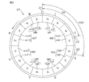
図9は、第1の磁石2Aの構成を示す模式図である。
The first rotation
FIG. 9 is a schematic diagram showing the configuration of the
第1の磁石2Aは、円筒状であり、第1の実施形態の磁石2と同様に周方向に等角度間隔で配された8個の磁極対M1〜M8を有している。つまり、第1の磁石2Aは、等角度間隔で配置された16個の磁極m1〜m16を有している。第1の磁石2Aにおける各磁極対M1〜M8に対応する角度領域を、それぞれ第1領域I〜第8領域VIIIという場合がある。各領域I〜VIIIの角度幅は、45°(機械角)である。
The
第1の磁石2A内の磁極対における磁力の大きさの種類には、磁力が大きい第1の磁力と第1の磁力より磁力が小さい第2の磁力との2種類がある。第1の磁石2Aにおける第1の磁力を有する磁極対と第2の磁力を有する磁極対との配置パターンは、第1の実施形態の磁石2の8つの磁極対の配置パターンと同じである。具体的には、8個の磁極対M1〜M8のうち、M1,M2,M3,M5の磁力が第2の磁力(弱い磁力)に設定され、相対的磁極対番号がM4,M6,M7,M8の磁力が第1の磁力(強い磁力)に設定されている。
There are two types of the magnitude of the magnetic force in the magnetic pole pair in the
第1の磁石2Aの周囲には、3つの磁気センサ21,22,23が配置されている。これら3つの磁気センサ21,22,23を、それぞれ第1の磁気センサ21、第2の磁気センサ22および第3の磁気センサ23という場合がある。図9おいて、第2の磁気センサ22は、第1の磁気センサ21に対して、第1の磁石2Aの回転中心軸を中心として、時計方向に75°(電気角では600°)だけ離れた位置に配置されている。第3の磁気センサ23は、第1の磁気センサ21に対して、第1の磁石2Aの回転中心軸を中心として、時計方向に105°(電気角では840°)だけ離れた位置に配置されている。
Three
言い換えると、第1の磁気センサ21が第1の磁極対M1における電気角で0°に対向しているときには、第2の磁気センサ22が第2の磁極対M2における電気角で240°に対向し、第3の磁気センサ23が第3の磁極対M3における電気角で120°に対向するように、3つの磁気センサ21,22,23が配置されている。
図9に矢印で示す方向を第1の磁石2Aの正方向の回転方向とする。そして、第1の磁石2Aが正方向に回転されると第1の磁石2Aの回転角が大きくなり、第1の磁石2Aが逆方向に回転されると、第1の磁石2Aの回転角が小さくなるものとする。各磁気センサ21,22,23からは、第1の磁石2Aが1磁極対分に相当する角度(45°(電気角では360°))を回転する期間を一周期とする正弦波信号V1,V2,V3が出力される。
In other words, when the first
The direction indicated by the arrow in FIG. 9 is the positive direction of rotation of the
第1の磁石2Aの1回転分の角度範囲を、8個の磁極対M1〜M8に対応して8個の区間に分け、各区間の開始位置を0°とし終了位置を360°として表した第1の磁石2Aの角度を、第1の磁石2Aの電気角(出力軸52の電気角)θeAということにする。
ここでは、第1の磁気センサ21からは、8個の磁極対M1〜M8に対応する区間毎に、V1=A1・sinθeAの出力信号が出力されるものとする。この場合、第2の磁気センサ22からは、8個の磁極対M1〜M8に対応する区間毎に、V2=A2・sin(θeA+600°)=A2・sin(θeA+240°)の出力信号が出力される。また、第3の磁気センサ23からは、8個の磁極対M1〜M8に対応する区間毎に、V3=A3・sin(θeA+840°)=A3・sin(θeA+120°)の出力信号が出力される。A1,A2,A3は、それぞれ振幅を表している。ただし、振幅A1,A2,A3は、各磁極対M1〜M8の磁力の大きさに応じて変化する。
The angle range for one rotation of the
Here, it is assumed that an output signal of V1 = A1 · sin θeA is output from the first
したがって、各磁気センサ21,22,23からは、互いに所定の位相差120°(電気角)を有する正弦波信号が出力される。各磁気センサ21,22,23の出力信号21,22,23を、それぞれ第1の出力信号V1,第2の出力信号V2および第3の出力信号V3という場合がある。
図8に戻り、各磁気センサ21,22,23の出力信号21,22,23は、第1の回転角演算部20Aに入力される。第1の回転角演算部20Aは、第1の実施形態における回転角演算装置20による回転角演算処理(図5参照)と同様な回転角演算処理を行なうことにより、第1の磁気センサ21が感知している磁極対に対応する領域の領域番号I〜VIIIを特定するとともに、第1の磁石2A(出力軸52)の回転角(電気角θeAおよび機械角θmA)を演算する。
Therefore, each
Returning to FIG. 8, the output signals 21, 22, and 23 of the
図10は、第2の磁石2Bを示す模式図である。
第2の磁石2Bは、円筒状であり、周方向に等角度間隔で配された32個の磁極対M1〜M32を有している。つまり、第2の磁石2Bは、等角度間隔で配置された64個の磁極を有している。32個の磁極対M1〜M32のうち、M1〜M8からなる磁極対群を第1グループG1、M9〜M16からなる磁極対群を第2グループG2、M17〜M24からなる磁極対群を第3グループG3、M25〜M32からなる磁極対群を第4グループG4という場合がある。
FIG. 10 is a schematic diagram showing the
The
各グループG1〜G4内の8つの磁極対に1〜8の数字を割り当てた番号を、相対的磁極対番号[1]〜[8]ということにする。
第2の磁石2B内の磁極対における磁力の大きさの種類には、磁力が大きい第1の磁力と第1の磁力より磁力が小さい第2の磁力との2種類がある。各グループG1〜G4における第1の磁力を有する磁極対と第2の磁力を有する磁極対との配置パターンは、第1の実施形態の磁石2の8つの磁極対M1〜M8の配置パターンと同じである。具体的には、各グループ内の8個の磁極対[1]〜[8]のうち、相対的磁極対番号が[1],[2],[3],[5]の磁力が第2の磁力(弱い磁力)に設定され、相対的磁極対番号が[4],[6],[7],[8]の磁力が第1の磁力(強い磁力)に設定されている。
The numbers obtained by assigning the
There are two types of the magnitude of the magnetic force in the magnetic pole pair in the
第2の磁石2Bの周囲には、3つの磁気センサ24,25,26が配置されている。これら3つの磁気センサ24,25,26を、それぞれ第4の磁気センサ24、第5の磁気センサ25および第6の磁気センサ26という場合がある。図10おいて、第5の磁気センサ25は、第4の磁気センサ24に対して、第2の磁石2Bの回転中心軸を中心として、時計方向に18.75°(電気角では600°)だけ離れた位置に配置されている。第6の磁気センサ26は、第4の磁気センサ24に対して、第2の磁石2Bの回転中心軸を中心として、時計方向に26.25°(電気角では840°)だけ離れた位置に配置されている。
Three
言い換えると、第4の磁気センサ24が第1の磁極対M1における電気角で0°に対向しているときには、第5の磁気センサ25が第2の磁極対M2における電気角で240°に対向し、第6の磁気センサ26が第3の磁極対M3における電気角で120°に対向するように、3つの磁気センサ24,25,26が配置されている。
図10に矢印で示す方向を第2の磁石2Bの正方向の回転方向とする。そして、第2の磁石2Bが正方向に回転されると第2の磁石2Bの回転角が大きくなり、第2の磁石2Bが逆方向に回転されると、第2の磁石2Bの回転角が小さくなるものとする。各磁気センサ24,25,26からは、第2の磁石2Bが1磁極対分に相当する角度(11.25°(電気角では360°))を回転する期間を一周期とする正弦波信号V4,V5,V6が出力される。
In other words, when the fourth magnetic sensor 24 faces the electrical angle of 0 ° in the first magnetic pole pair M1, the fifth
The direction indicated by the arrow in FIG. 10 is the positive direction of rotation of the
第2の磁石2Bの1回転分の角度範囲を、32個の磁極対M1〜M32に対応して32個の区間に分け、各区間の開始位置を0°とし終了位置を360°として表した第2の磁石2Bの角度を、第2の磁石2Bの電気角(入力軸51の電気角)θeBということにする。
ここでは、第4の磁気センサ24からは、32個の磁極対M1〜M32に対応する区間毎に、V4=A4・sinθeBの出力信号が出力されるものとする。この場合、第5の磁気センサ25からは、32個の磁極対M1〜M32に対応する区間毎に、V5=A5・sin(θeB+600°)=A5・sin(θeB+240°)の出力信号が出力される。また、第6の磁気センサ26からは、32個の磁極対M1〜M32に対応する区間毎に、V6=A6・sin(θeB+840°)=A6・sin(θeB+120°)の出力信号が出力される。A4,A5,A6は、それぞれ振幅を表している。ただし、振幅A4,A5,A6は、各磁極対M1〜M32の磁力の大きさに応じて変化する。
The angle range for one rotation of the
Here, the fourth magnetic sensor 24 outputs an output signal of V4 = A4 · sin θeB for each section corresponding to 32 magnetic pole pairs M1 to M32. In this case, the fifth
したがって、各磁気センサ24,25,26からは、互いに所定の位相差120°(電気角)を有する正弦波信号が出力される。各磁気センサ24,25,26の出力信号V4,V5,V6を、それぞれ第4の出力信号V4,第5の出力信号V5および第6の出力信号V6という場合がある。
図8に戻り、各磁気センサ24,25,26の出力信号V4,V5,V6は、第2の回転角演算部20Bに入力される。第2の回転角演算部20Bは、図11に示すような回転角演算処理を行なうことにより、第2の磁石2B(入力軸51)の回転角(電気角θeBおよび機械角θmB)を演算する。なお、第1の磁石2Aの磁極毎のピーク値および第2の磁石2Bの磁極毎のピーク値は、第1の実施形態と同様に、ピーク値テーブルとして不揮発性メモリに記憶されている。
Therefore, the
Returning to FIG. 8, the output signals V4, V5, and V6 of the
図11は、第2の回転角演算部20Bによる回転角演算処理部の手順を示すフローチャートである。
図11に示される回転角演算処理は、所定の演算周期毎に繰り返し行なわれる。
回転角演算処理開始時において第4の磁気センサ24が感知している磁極を基準磁極として、各磁極に相対的な番号を割り当てた場合の各磁極の番号を相対的極番号と定義する。第4の磁気センサ24が感知している磁極の相対的極番号(以下、「第4の相対的極番号」という)を変数r4で表し、第5の磁気センサ25が感知している磁極の相対的極番号(以下、「第5の相対的極番号」という)を変数r5で表し、第6の磁気センサ26が感知している磁極の相対的極番号(以下、「第6の相対的極番号」という)を変数r6で表すことにする。なお、各相対的極番号r4,r5,r6は、1〜64の整数をとり、1より1少ない相対的極番号は64となり、64より1大きい相対的極番号は1となるものとする。
FIG. 11 is a flowchart showing the procedure of the rotation angle calculation processing unit by the second rotation
The rotation angle calculation process shown in FIG. 11 is repeatedly performed every predetermined calculation cycle.
Using the magnetic pole sensed by the fourth magnetic sensor 24 at the start of the rotation angle calculation process as a reference magnetic pole, the number of each magnetic pole when a relative number is assigned to each magnetic pole is defined as a relative pole number. The relative pole number (hereinafter referred to as “fourth relative pole number”) of the magnetic pole sensed by the fourth magnetic sensor 24 is represented by a variable r4, and the magnetic pole sensed by the fifth
この実施形態では、回転角演算処理開始時において第4の磁気センサ24が感知している磁極(基準磁極)がN極の磁極である場合には、当該磁極に”1”の相対的極番号が割り当てられる。一方、回転角演算処理の開始時において第4の磁気センサ24が感知している磁極(基準磁極)がS極の磁極である場合には、当該磁極に”2”の相対的極番号が割り当てられる。 In this embodiment, when the magnetic pole (reference magnetic pole) sensed by the fourth magnetic sensor 24 at the start of the rotation angle calculation process is an N-pole magnetic pole, the relative pole number “1” is assigned to the magnetic pole. Is assigned. On the other hand, when the magnetic pole (reference magnetic pole) sensed by the fourth magnetic sensor 24 at the start of the rotation angle calculation process is an S pole, a relative pole number of “2” is assigned to the magnetic pole. It is done.
また、第4の磁気センサ24が感知している磁極の極番号をq4、第5の磁気センサ25が感知している磁極の極番号をq5、第6の磁気センサ26が感知している磁極の極番号をq6で表すことにする。なお、各極番号q4,q5,q6は、1〜48の整数をとり、1より1少ない極番号は64となり、64より1大きい極番号は1となるものとする。
また、第4の磁気センサ24が感知している相対的磁極対番号を[Q4]で表すことにする。なお、相対的磁極対番号[Q4]は、1〜8の整数をとり、1より1少ない極番号は8となり、8より1大きい極番号は1となるものとする。また、第4の磁気センサ24が感知している磁極対の磁極対番号(絶対的磁極対番号)をQ4で表すことにする。なお、絶対的磁極対番号Q4は、1〜32の整数をとり、1より1少ない極番号は32となり、32より1大きい極番号は1となるものとする。
The pole number of the magnetic pole sensed by the fourth magnetic sensor 24 is q4, the pole number of the magnetic pole sensed by the fifth
The relative magnetic pole pair number sensed by the fourth magnetic sensor 24 is represented by [Q4]. The relative magnetic pole pair number [Q4] takes an integer of 1 to 8, and the pole number that is 1 less than 1 is 8, and the pole number that is 1 greater than 8 is 1. Further, the magnetic pole pair number (absolute magnetic pole pair number) of the magnetic pole pair sensed by the fourth magnetic sensor 24 is represented by Q4. The absolute magnetic pole pair number Q4 takes an integer of 1 to 32. A pole number less than 1 by 1 is 32, and a pole number greater than 32 by 1 is 1.
回転角演算処理が開始されると、回転角演算装置20は、各磁気センサ24,25,26の出力信号(センサ値)V4,V5,V6を読み込む(ステップS1B)。なお、回転角演算部20Bのメモリ(たとえば、RAM)には、所定回数前に読み込まれたセンサ値から最新に読み込まれたセンサ値までの、複数回数分のセンサ値が記憶されるようになっている。
When the rotation angle calculation process is started, the rotation
また、この実施形態では、センサ値V4のピーク値(極大値および極小値)を検出するために、読み込まれたセンサ値V4のうち絶対値がより大きいセンサ値が、センサ値V4のピーク値候補としてメモリに保存される。同様に、センサ値V5のピーク値(極大値および極小値)を検出するために、読み込まれたセンサ値V5のうち絶対値がより大きいセンサ値が、センサ値V5のピーク値候補としてメモリに保存される。同様に、センサ値V6のピーク値(極大値および極小値)を検出するために、読み込まれたセンサ値V6のうち絶対値がより大きいセンサ値が、センサ値V6のピーク値候補としてメモリに保存される。ただし、これらのピーク値候補は、対応する出力信号のゼロクロスが検出されたときには、後述するような所定のタイミングでゼロにリセットされる。 In this embodiment, in order to detect a peak value (maximum value and minimum value) of the sensor value V4, a sensor value having a larger absolute value among the read sensor values V4 is a peak value candidate of the sensor value V4. Is stored in memory. Similarly, in order to detect the peak value (maximum value and minimum value) of the sensor value V5, a sensor value having a larger absolute value among the read sensor values V5 is stored in the memory as a peak value candidate of the sensor value V5. Is done. Similarly, in order to detect the peak value (maximum value and minimum value) of the sensor value V6, a sensor value having a larger absolute value among the read sensor values V6 is stored in a memory as a peak value candidate of the sensor value V6. Is done. However, these peak value candidates are reset to zero at a predetermined timing as will be described later when a zero cross of the corresponding output signal is detected.
前記ステップS1Bで各センサ値V4,V5,V6が読み込まれると、第2の回転角演算部20Bは、今回の処理が回転角演算処理開始後の初回の処理であるか否かを判別する(ステップS2B)。今回の処理が回転角演算処理開始後の初回の処理である場合には(ステップS2B:YES)、第2の回転角演算部20Bは、相対的極番号の設定処理を行う(ステップS3B)。
When the sensor values V4, V5, and V6 are read in step S1B, the second rotation
この相対的極番号の設定処理は、図6を用いて説明した相対的極番号の設定処理と同様である。ただし、図6における第1〜第3の出力信号V1,V2,V3は、それぞれ第4〜第6の出力信号V4,V5,V6に置き換えられる。また、図6における第1〜第3の相対的極番号r1,r2,r3は、それぞれ第4〜第6のr4,r5,r6に置き換えられる。 The relative pole number setting process is the same as the relative pole number setting process described with reference to FIG. However, the first to third output signals V1, V2, and V3 in FIG. 6 are replaced with fourth to sixth output signals V4, V5, and V6, respectively. Also, the first to third relative pole numbers r1, r2, and r3 in FIG. 6 are replaced with fourth to sixth r4, r5, and r6, respectively.
ステップS3Bの相対的極番号の設定処理が終了すると、第2の回転角演算部20Bは、ステップS12Bに移行する。
前記ステップS2Bにおいて、今回の処理が回転角演算処理開始後の初回の処理ではないと判別された場合には(ステップS2B:NO)、ステップS4Bに移行する。
ステップS4Bでは、第2の回転角演算部20Bは、メモリに記憶されているセンサ値V4,V5,V6に基づいて、センサ値V4,V5,V6毎に、センサ値の符号が反転するゼロクロスを検出したか否かを判別する。ゼロクロスが検出されなかったときには(ステップS4B:NO)、第2の回転角演算部20Bは、ステップS12Bに移行する。
When the relative pole number setting process in step S3B ends, the second rotation
If it is determined in step S2B that the current process is not the first process after the start of the rotation angle calculation process (step S2B: NO), the process proceeds to step S4B.
In step S4B, the second rotation
前記ステップS4Bにおいて、いずれかのセンサ値V4,V5,V6に対してゼロクロスが検出された場合には(ステップS4B:YES)、第2の回転角演算部20Bは、後述するステップS10Bの極番号特定処理によって、各磁極センサ24,25,26が検知している磁極が既に特定されているか否かを判別する(ステップS5B)。
各磁極センサ24,25,26が検知している磁極が特定されていない場合には、第2の回転角演算部20Bは、相対的極番号の更新処理を行なう(ステップS6B)。具体的には、前記ステップS4Bでゼロクロスが検出された磁気センサに対して現在設定されている相対的極番号r4、r5またはr6を、ロータ1の回転方向に基づいて更新する。より具体的には、第2の回転角演算部20Bは、第2の磁石2Bの回転方向が正方向(図10に矢印で示す方向)である場合には、前記ステップS4Bでゼロクロスが検出された磁気センサに対して現在設定されている相対的極番号r4、r5またはr6を、1だけ大きい番号に更新する。一方、第2の磁石2Bの回転方向が逆方向である場合には、第2の回転角演算部20Bは、当該磁気センサに対して現在設定されている相対的極番号r4、r5またはr6を、1だけ小さい番号に更新する。
If a zero cross is detected for any one of the sensor values V4, V5, V6 in step S4B (step S4B: YES), the second
If the magnetic pole detected by each of the
前記ステップS6Bの相対的極番号の更新処理が終了すると、第2の回転角演算部20Bは、ピーク値検出処理を行なう(ステップS7B)。ピーク値検出処理について具体的に説明する。前記ステップS4Bでゼロクロスが検出された出力信号に対応する磁気センサをピーク値検出対象の磁気センサということにする。第2の回転角演算部20Bは、まず、ピーク値検出対象の磁気センサが感知している磁極が変化したか否かを判別する。すなわち、第2の回転角演算部20Bは、前回ゼロクロスが検出されたときの第2の磁石2Bの回転方向と、現在の第2の磁石2Bの回転方向が同じ方向であれば、ピーク値検出対象の磁気センサが感知している磁極が変化したと判定する。一方、前回ゼロクロスが検出されたときの第2の磁石2Bの回転方向と、現在の第2の磁石2Bの回転方向が異なっていれば、第2の回転角演算部20Bは、ピーク値検出対象の磁気センサが感知している磁極が変化していないと判定する。
When the update process of the relative pole number in step S6B is completed, the second rotation
ピーク値検出対象の磁気センサが感知している磁極が変化したと判定された場合には、第2の回転角演算部20Bは、ピーク値を検出したと判別するとともに、当該磁気センサに対応するピーク値候補をピーク値として特定する。一方、ピーク値検出対象の磁気センサが感知している磁極が変化していないと判定された場合には、第2の回転角演算部20Bは、ピーク値を検出しなかったと判定する。なお、ピーク値には、0より大きな極大値と、0より小さな極小値とがある。この実施形態では、ピーク値のうち、極大値に基づいて、第4の磁気センサ24が感知している磁極対が特定されるものとする。以下において、ピーク値検出処理において検出された第4の出力信号V4、第5の出力信号V5および第6の出力信号V6の極大値を、それぞれP4、P5およびP6で表す場合がある。
When it is determined that the magnetic pole sensed by the peak value detection target magnetic sensor has changed, the second rotation
ピーク値検出処理において極大値が検出されなかった場合には(ステップS8B:NO)、第2の回転角演算部20Bは、前記ステップS4Bでゼロクロスが検出された出力信号に対応するピーク値候補を0にリセットした後、ステップS12Bに移行する。一方、ピーク値検出処理において極大値が検出されたときには(ステップS8B:YES)、当該極大値を、前記ステップS4Bでゼロクロスが検出された出力信号に対する極大値P4、P5またはP6として記憶する(ステップS9B)。そして、第2の回転角演算部20Bは、前記ステップS4Bでゼロクロスが検出された出力信号に対応するピーク値候補を0にリセットした後、ステップS10Bに移行する。
When the maximum value is not detected in the peak value detection process (step S8B: NO), the second rotation
ステップS10Bでは、第2の回転角演算部20Bは、極番号特定処理(磁極対特定処理)を行なう。
第1の実施形態における8個の磁極対M1〜M8の配列を磁力の強弱で表した磁極対パターンを基準磁極対パターンということにすると、第2の磁石2Bにおける各グループG1〜G4内の磁極対パターンは、基準磁極対パターンと同じパターンとなる。このため、第2の回転角演算部20Bは、図5のステップS10において第1の磁気センサ21が感知している磁極対の磁極対番号Q1を特定した方法と同様な方法によって、第4の磁気センサ24が感知している磁極対の相対的磁極対番号[Q4]を特定することができる。
In step S10B, the second rotation
When the magnetic pole pair pattern in which the arrangement of the eight magnetic pole pairs M1 to M8 in the first embodiment is expressed by the strength of the magnetic force is referred to as a reference magnetic pole pair pattern, the magnetic poles in the groups G1 to G4 in the
つまり、第2の回転角演算部20Bは、予め設定された、第4の磁気センサ24が感知している磁極対の相対的磁極対番号[1]〜[8]と各出力信号V4,V5,V6の極大値P4,P5,P6の組合せとの関係と、最新に検出された各出力信号V4,V5,V6の極大値と、第2の磁石2Bの回転方向とに基づいて、第4の磁気センサ24が感知している磁極対の相対的磁極対番号[Q4]を特定する(第1の磁極対特定処理)。
That is, the second rotation
次に、第2の回転角演算部20Bは、第4の磁気センサ24が感知している磁極対の相対的磁極対番号[Q4]と、第1の回転角演算部20Aによって特定された、第1の磁気センサ21が感知している磁極対に対応する領域番号I〜VIIIとに基づいて、第4の磁気センサ24が感知している磁極対の絶対的磁極対番号Q4を特定する(第2の磁極対特定処理)。
Next, the second rotation
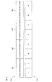
図12は、トーションバー53に捩れがない場合における、第1の磁石2Aの各領域I〜VIIIと、第2の磁石2Bの各グループG1〜G4との相対的な位置関係を模式的に表している模式図である。
第2の回転角演算部20Bによって、第4の磁気センサ24が感知している磁極対の相対的磁極対番号が[8]であると特定されたとする。この場合には、第4の磁気センサ24が感知している磁極対は、M8,M16,M34およびM32のうちのいずれかである。
FIG. 12 schematically shows the relative positional relationship between the regions I to VIII of the
It is assumed that the relative magnetic pole pair number of the magnetic pole pair sensed by the fourth magnetic sensor 24 is specified by the second rotation
第4の磁気センサ24が感知している磁極対が第1グループG1内のM8であるとすると、トーションバー53の捩れ角の絶対値の最大値は機械角で15°以下と考えられるため、第1の磁気センサ21が感知している磁極対は領域IIまたはIIIのいずれかになる。第4の磁気センサ24が感知している磁極対が第2グループG2内のM16であるとすると、第1の磁気センサ21が感知している磁極対は領域IVまたはVのいずれかになる。
If the magnetic pole pair sensed by the fourth magnetic sensor 24 is M8 in the first group G1, the maximum value of the absolute value of the torsion angle of the
第4の磁気センサ24が感知している磁極対が第3グループG3内のM24であるとすると、第1の磁気センサ21が感知している磁極対は領域VIまたはVIIのいずれかになる。第4の磁気センサ24が感知している磁極対が第4グループG4内のM32であるとすると、第1の磁気センサ21が感知している磁極対は領域VIIIまたはIのいずれかになる。
Assuming that the magnetic pole pair sensed by the fourth magnetic sensor 24 is M24 in the third group G3, the magnetic pole pair sensed by the first
したがって、第4の磁気センサ24が感知している磁極対の相対的磁極対番号が、第2の回転角演算部20Bによって[8]であると特定された場合には、第1の磁気センサ21が感知している磁極対に対応する領域番号I〜VIIIに基づいて、第4の磁気センサ24が感知している磁極対がM8,M16,M24,M32のいずれであるかを特定することができる。
Therefore, when the relative magnetic pole pair number of the magnetic pole pair sensed by the fourth magnetic sensor 24 is specified as [8] by the second rotation
第2の回転角演算部20Bによって特定された相対的磁極対番号が[8]以外の値であるときにおいても同様に、第1の回転角演算部20Aによって特定された、第1の磁気センサ21が感知している磁極対に対応する領域番号I〜VIIIを考慮して、第4の磁気センサ24が感知している磁極対(絶対的磁極対番号)Q4を特定することができる。
表2は、第4の磁気センサ24が感知している磁極対の相対的磁極対番号[Q4]と第1の磁気センサ21が感知している磁極対に対応する領域番号I〜VIIIとの組合せと、第4の磁気センサ24が感知している磁極対の絶対的磁極対番号Q4との関係を表している。
Similarly, when the relative magnetic pole pair number specified by the second rotation
Table 2 shows the relative magnetic pole pair number [Q4] of the magnetic pole pair sensed by the fourth magnetic sensor 24 and the region numbers I to VIII corresponding to the magnetic pole pairs sensed by the first
つまり、第2の回転角演算部20Bは、第4の磁気センサ24が感知している磁極対の相対的磁極対番号[Q4]と、第1の回転角演算部20Bによって特定された領域番号I〜VIII(第1の磁気センサ21が感知している磁極対に対応する領域番号)と、表2の内容とに基づいて、第4の磁気センサ24が感知している磁極対の絶対的磁極対番号Q4を特定する。
That is, the second rotation
第1の実施形態で説明したように、第2の磁石2Bの回転方向が正方向(図10に矢印で示す方向)である場合には、第4の磁気センサ24が感知している磁極は、第4の磁気センサ24が感知している磁極対内の磁極のうち、N極の磁極となる。したがって、この場合には、第2の回転角演算部20Bは、第4の磁極センサ24が現在感知している磁極の極番号q4を、q4=2・Q4−1に基づいて特定する。また、第2の回転角演算部20Bは、q5=(q4−r4)+r5に基づいて、第5の磁気センサ25が感知している磁極の極番号q5を特定する。さらに、第2の回転角演算部20Bは、q6=(q4−r4)+r6に基づいて、第6の磁気センサ26が感知している磁極の極番号q6を特定する。そして、ステップS12Bに移行する。
As described in the first embodiment, when the rotation direction of the
一方、第2の磁石2Bの回転方向が逆方向である場合には、第4の磁気センサ24が感知している磁極は、第4の磁気センサ24が感知している磁極対内の磁極のうち、S極の磁極となる。したがって、この場合には、第2の回転角演算部20Bは、第4の磁極センサ24が現在感知している磁極の極番号q4を、q4=2・Q4に基づいて特定する。また、第2の回転角演算部20Bは、q5=(q4−r4)+r5に基づいて、第5の磁気センサ25が感知している磁極の極番号q5を特定する。さらに、第2の回転角演算部20Bは、q6=(q4−r4)+r6に基づいて、第6の磁気センサ26が感知している磁極の極番号q6を特定する。そして、ステップS12Bに移行する。
On the other hand, when the rotation direction of the
なお、前記ステップS10Bにおいて、3つの出力信号V4,V5,V6の極大値が検出(記憶)されていないと判別された場合等のように、第4の磁気センサ24が感知している磁極対を特定することができなかった場合には、第2の回転角演算部20Bは、前述した極番号特定処理を行なうことなく、ステップS12Bに移行する。
前記ステップS5Bにおいて、各磁気センサ24,25,26が感知している磁極が既に特定されていると判別された場合には(ステップS5B:YES)、第2の回転角演算部20Bは、前記ステップS4Bでゼロクロスが検出された出力信号に対応するピーク値候補を0にリセットした後、極番号の更新処理を行なう(ステップS11B)。具体的には、第2の磁石2Bの回転方向が正方向である場合には、ゼロクロスが検出された磁気センサに対して既に特定されている前記極番号q4、q5またはq6を、1だけ大きい極番号に更新し、第2の磁石2Bの回転方向が逆方向である場合には、ゼロクロスが検出された磁気センサに対して既に特定されている前記極番号q4、q5またはq6を、1だけ小さい極番号に更新する。第2の回転角演算部20Bは、ステップS11Bの極番号の更新処理が終了すると、ステップS12Bに移行する。
It should be noted that the magnetic pole pair sensed by the fourth magnetic sensor 24, such as when it is determined in step S10B that the maximum values of the three output signals V4, V5, V6 have not been detected (stored). Can not be specified, the second rotation
If it is determined in step S5B that the magnetic poles sensed by the
ステップS12Bでは、第2の回転角演算部20Bは、振幅補正処理を行う。つまり、第2の回転角演算部20Bは、各磁気センサ24,25,26が感知している磁極の極番号q4,q4,q5が特定されている場合には、各磁気センサ24,25,26の出力信号V4,V5,V6の振幅を補正する。この振幅補正処理は、図5のステップS12で説明した振幅補正処理と同様なので、その説明を省略する。一方、各磁気センサ24,25,26が感知している磁極の極番号q4,q5,q6が特定されていない場合には、第2の回転角演算部20Bは、振幅補正処理を行うことなく、ステップS13Bに移行する。
In step S12B, the second
振幅補正処理が終了すると、第2の回転角演算部20Bは、前記ステップS12Bで振幅補正された各出力信号V4’,V5’,V6’ に基づいて、入力軸51の電気角θeBを演算する(ステップS13B)。ただし、前記ステップS12Bで振幅補正がされなかった場合には、前記ステップS1Bで読み込まれたセンサ値V1,V2,V3に基づいて、電気角θeを演算する。ステップS13Bで行なわれる電気角θeBの演算処理は、図5のステップS13で説明した電気角θeの演算処理と同様なので、その説明を省略する。
When the amplitude correction process is completed, the second rotation
前記ステップS13で電気角θe2が演算されると、第2の回転角演算部20Bは、入力軸51の機械角(絶対角)θmBを演算する(ステップS14B)。具体的には、第2の回転角演算部20Bは、前記ステップS13Bで演算された電気角θeBと第4の磁気センサ24が感知している極番号q4に対応する磁極対番号Q4とを用い、次式(14)に基づいて、機械角θmBを演算する。
When the electrical angle θe2 is calculated in step S13, the second rotation
θmB={θeB+(Q4−1)×360°}/32 …(14)
トルク演算部20Cは、第1の回転角演算部20Aによって演算される出力軸52の機械角θmAと、第2の回転角演算部20Bによって演算される入力軸51の機械角θmBと、トーションバー53のばね定数Kとに基づいて操舵トルクTを演算する。具体的には、 トルク演算部20Cは、次式(15)に基づいて、操舵トルクTを演算する。
θmB = {θeB + (Q4-1) × 360 °} / 32 (14)
The torque calculator 20C includes a mechanical angle θmA of the
T=(θmA−θmB)×K …(15)
前記実施形態では、操舵トルクTを演算することができる。また、入力軸51の回転角(機械角)である操舵角θmBおよび出力軸52の回転角(機械角)θmAを演算することができる。入力軸51に固定された第2の磁石2Bには、32個の磁極対が設けられているため、回転角演算処理開始後において、入力軸51が回転を開始した直後のきわめて早い段階で、操舵角θmBを演算できるようになる。
T = (θmA−θmB) × K (15)
In the embodiment, the steering torque T can be calculated. Further, the steering angle θmB that is the rotation angle (mechanical angle) of the
前記実施形態では、第1の磁石2Aには、図9に示されるように、8つの磁極対M1〜M8が設けられているが、第1の磁石2Aに16、24または32個の磁極対M1〜M8が設けられていてもよい。このようにすると、図9および図12に示される第1の磁石2Aの各領域I〜VIII内には、それぞれ、2、4または8個の磁極対が含まれることになる。この場合には、第1〜第3の磁気センサ21,22,23は、それらの間の電気角での角度間隔が、図9に示される第1〜第3の磁気センサ21,22,23の間の電気角での角度間隔と等しくなるように配置される。
In the embodiment, as shown in FIG. 9, the
また、この場合、第1の磁石2Aにおける同じ領域に含まれる複数の磁極対の磁力は同じ強さに設定される。そして、第1の磁石2Aの各領域I〜VIII内の磁極対の強さは、図9に示される第1の磁石2Aにおいて対応する領域I〜VIII内の磁極対M1〜M8の磁力と同じに設定される。たとえば、第1の磁石2Aの領域I内に含まれる各磁極対の磁力の強さは、前述した第1の磁石2Aの磁極対M1の磁力の強さと同じとなる。
In this case, the magnetic forces of the plurality of magnetic pole pairs included in the same region of the
このようにすると、第1の磁気センサ21が感知している領域I〜VIII毎に、3つの出力信号V1,V2,V3の極大値の組合せが異なるので、3つの出力信号V1,V2,V3の極大値の組合せに基づいて、第1の磁気センサ21が感知している領域を特定することが可能となる。
この発明は、特許請求の範囲に記載された事項の範囲で種々の設計変更を施すことが可能である。
In this case, the combinations of the maximum values of the three output signals V1, V2, and V3 are different for each of the regions I to VIII sensed by the first
The present invention can be modified in various ways within the scope of the matters described in the claims.
1…検出用ロータ、2,2A,2B…磁石、21〜26…磁気センサ、10…ブラシレスモータ、20…回転角演算装置、20A…第1の回転角演算部、20B…第2の回転角演算部、20C…トルク演算部、51…入力軸、52…出力軸、53…トーションバー、60…ECU
DESCRIPTION OF
Claims (5)
前記回転体の回転に応じて回転し、第1の磁力を有する1または複数の磁極対と第2の磁力を有する1または複数の磁極対とを備えている多極磁石と、
前記多極磁石の回転に応じて、互いに位相差を有する複数の正弦波信号をそれぞれ出力する複数の磁気センサと、
各磁気センサの出力信号のピーク値をそれぞれ検出するピーク値検出手段と、
前記ピーク値検出手段によって検出された各磁気センサのピーク値の組み合わせに基づいて、基準となる1つの磁気センサが感知している磁極対を特定する磁極対特定手段とを含み、
各磁気センサのピーク値の組み合わせが、前記基準となる磁気センサが感知している磁極対毎に異なるように、前記磁極対の数、前記磁気センサの数、前記第1の磁力を有する磁極対と前記第2の磁力を有する磁極対との配置パターンおよび前記磁気センサの配置位置が設定されている、回転角検出装置。 A rotation angle detection device for detecting a rotation angle of a rotating body,
A multipolar magnet that rotates in accordance with the rotation of the rotating body and includes one or more magnetic pole pairs having a first magnetic force and one or more magnetic pole pairs having a second magnetic force;
A plurality of magnetic sensors that respectively output a plurality of sinusoidal signals having phase differences according to the rotation of the multipole magnet;
A peak value detecting means for detecting the peak value of the output signal of each magnetic sensor;
Magnetic pole pair specifying means for specifying a magnetic pole pair sensed by one magnetic sensor based on a combination of peak values of each magnetic sensor detected by the peak value detecting means,
The number of the magnetic pole pairs, the number of the magnetic sensors, and the magnetic pole pairs having the first magnetic force so that combinations of peak values of the magnetic sensors are different for each magnetic pole pair sensed by the reference magnetic sensor. And an arrangement position of the magnetic pole pair having the second magnetic force and an arrangement position of the magnetic sensor are set.
前記磁極特定手段の磁極特定結果に基づいて、少なくとも2つの磁気センサの出力信号の振幅を補正する振幅補正手段と、
振幅補正手段によって振幅が補正された少なくとも2つの出力信号に基づいて、前記回転体の回転角を検出する回転角演算手段とを、さらに含む請求項1に記載の回転角検出装置。 Magnetic pole specifying means for specifying a magnetic pole sensed by at least two magnetic sensors based on the magnetic pole pair specifying result of the magnetic pole pair specifying means;
Amplitude correcting means for correcting the amplitudes of the output signals of at least two magnetic sensors based on the magnetic pole specifying result of the magnetic pole specifying means;
The rotation angle detection device according to claim 1, further comprising a rotation angle calculation unit that detects a rotation angle of the rotating body based on at least two output signals whose amplitudes are corrected by the amplitude correction unit.
前記複数の磁気センサは、第1〜第3の3つの磁気センサからなり、
前記第1の磁気センサが前記第1の磁極対における電気角で0°に対向しているときには、前記第2の磁気センサが前記第2の磁極対における電気角で240°に対向し、前記第3の磁気センサが前記第3の磁極対における電気角で120°に対向するように、前記3つの磁気センサが配置されている、請求項1または2に記載の回転角検出装置。 The plurality of magnetic pole pairs includes first to eighth eight magnetic pole pairs,
The plurality of magnetic sensors includes first to third three magnetic sensors,
When the first magnetic sensor is opposed to 0 ° in electrical angle in the first magnetic pole pair, the second magnetic sensor is opposed to 240 ° in electrical angle in the second magnetic pole pair, and 3. The rotation angle detection device according to claim 1, wherein the three magnetic sensors are arranged so that the third magnetic sensor is opposed to an electrical angle of 120 ° in the third magnetic pole pair.
請求項1〜請求項3のいずれか一項に記載の回転角検出装置である基本の回転角検出装置と同じ構成または前記基本の回転角検出装置に対して前記多極磁石の構成以外は同じ構成を有し、前記第1軸の回転角を検出するための第1の回転角検出装置と、
前記基本の回転角検出装置に対して前記多極磁石の構成以外は同じ構成を有し、前記第2軸の回転角を検出するための第2の回転角検出装置とを含み、
前記第1の回転角検出装置における多極磁石は、前記基本の回転角検出装置における多極磁石の各磁極対が、当該磁極対と同じ磁力を有する1または複数の磁極対からなる構成を有しており、
前記第1の回転角検出装置における磁極対特定手段は、前記基本の回転角検出装置における多極磁石における各磁極対に対応する角度領域を表す領域番号のうち、前記第1の回転角検出装置において基準となる磁気センサが感知している角度領域に対応する領域番号を特定するように構成されており、
前記基本の回転角検出装置における複数の磁極対の配列を磁力の強弱の配列で表した磁極対パターンを基準磁極対パターンとすると、前記第2の回転角演算装置における多極磁石は、前記基準磁極対パターンがn(nは2以上の整数)回繰り返された磁極対パターンを有しており、
前記第2の回転角検出装置における磁極対特定手段は、第1の磁極対特定手段と、第2の磁極対特定手段とを含み、
前記第1の磁極対特定手段は、前記第2の回転角検出装置の多極磁石が有する磁極対パターンに含まれる各基準磁極対パターン内での各磁極対の順番を表す番号を相対的磁極対番号と定義すると、前記第2の回転角検出装置において基準となる磁気センサが感知している磁極対に対応する相対的磁極対番号を特定するように構成されており、
前記第2の磁極対特定手段は、前記第1の磁極対特定手段によって特定された相対的磁極対番号と、前記第1の回転角演算装置における前記磁極対特定手段によって特定された領域番号とに基づいて、前記第2の回転角検出装置において基準となる磁気センサが感知している磁極対を特定するように構成されている、トルク検出装置。 Including a connecting shaft that connects the first shaft and the second shaft, and based on a relative rotational displacement amount of the first shaft and the second shaft caused by torsion of the connecting shaft, the first shaft and the second shaft A torque detection device for detecting torque applied to two axes,
The same configuration as the basic rotation angle detection device which is the rotation angle detection device according to any one of claims 1 to 3, or the same as the basic rotation angle detection device except for the configuration of the multipolar magnet. A first rotation angle detection device for detecting a rotation angle of the first axis;
The basic rotation angle detection device has the same configuration except for the configuration of the multipolar magnet, and includes a second rotation angle detection device for detecting the rotation angle of the second shaft,
The multipolar magnet in the first rotation angle detection device has a configuration in which each magnetic pole pair of the multipolar magnet in the basic rotation angle detection device includes one or more magnetic pole pairs having the same magnetic force as the magnetic pole pair. And
The magnetic pole pair specifying means in the first rotation angle detection device includes the first rotation angle detection device among region numbers representing angle regions corresponding to magnetic pole pairs in the multipolar magnet in the basic rotation angle detection device. Is configured to identify an area number corresponding to the angular area sensed by the reference magnetic sensor,
When a magnetic pole pair pattern in which the arrangement of a plurality of magnetic pole pairs in the basic rotation angle detection device is represented by an arrangement of strong and weak magnetic forces is a reference magnetic pole pair pattern, the multipolar magnet in the second rotation angle calculation device is the reference The magnetic pole pair pattern has a magnetic pole pair pattern that is repeated n (n is an integer of 2 or more) times,
The magnetic pole pair specifying means in the second rotation angle detecting device includes a first magnetic pole pair specifying means and a second magnetic pole pair specifying means,
The first magnetic pole pair specifying means assigns a number indicating the order of each magnetic pole pair in each reference magnetic pole pair pattern included in the magnetic pole pair pattern included in the multipolar magnet of the second rotation angle detection device to the relative magnetic pole. When defined as a pair number, a relative magnetic pole pair number corresponding to a magnetic pole pair sensed by a magnetic sensor serving as a reference in the second rotation angle detection device is specified.
The second magnetic pole pair specifying means includes a relative magnetic pole pair number specified by the first magnetic pole pair specifying means, and an area number specified by the magnetic pole pair specifying means in the first rotation angle calculation device. The torque detection device is configured to identify a magnetic pole pair sensed by a magnetic sensor serving as a reference in the second rotation angle detection device.
前記第2の回転角検出装置は、前記第2軸の回転角を操舵角として検出するように構成されている、請求項4に記載のトルク検出装置。 A torque detection device in a vehicle steering device,
The torque detection device according to claim 4, wherein the second rotation angle detection device is configured to detect a rotation angle of the second shaft as a steering angle.
Priority Applications (4)
| Application Number | Priority Date | Filing Date | Title |
|---|---|---|---|
| JP2011051638A JP2012189376A (en) | 2011-03-09 | 2011-03-09 | Rotation angle detection device and torque detection device |
| US13/407,935 US8607648B2 (en) | 2011-03-09 | 2012-02-29 | Rotation angle detection device and torque detection device |
| EP12158142A EP2498064A2 (en) | 2011-03-09 | 2012-03-05 | Rotation Angle Detection Device and Torque Detection Device |
| CN2012100574399A CN102853758A (en) | 2011-03-09 | 2012-03-06 | Rotation angle detection device and torque detection device |
Applications Claiming Priority (1)
| Application Number | Priority Date | Filing Date | Title |
|---|---|---|---|
| JP2011051638A JP2012189376A (en) | 2011-03-09 | 2011-03-09 | Rotation angle detection device and torque detection device |
Publications (1)
| Publication Number | Publication Date |
|---|---|
| JP2012189376A true JP2012189376A (en) | 2012-10-04 |
Family
ID=45841261
Family Applications (1)
| Application Number | Title | Priority Date | Filing Date |
|---|---|---|---|
| JP2011051638A Withdrawn JP2012189376A (en) | 2011-03-09 | 2011-03-09 | Rotation angle detection device and torque detection device |
Country Status (4)
| Country | Link |
|---|---|
| US (1) | US8607648B2 (en) |
| EP (1) | EP2498064A2 (en) |
| JP (1) | JP2012189376A (en) |
| CN (1) | CN102853758A (en) |
Cited By (2)
| Publication number | Priority date | Publication date | Assignee | Title |
|---|---|---|---|---|
| WO2017030088A1 (en) * | 2015-08-19 | 2017-02-23 | 株式会社デンソー | Electric motor |
| CN113740727A (en) * | 2020-05-13 | 2021-12-03 | 广东威灵电机制造有限公司 | Motor pole pair number detection method and device and motor controller |
Families Citing this family (9)
| Publication number | Priority date | Publication date | Assignee | Title |
|---|---|---|---|---|
| EP2936097A1 (en) * | 2012-12-21 | 2015-10-28 | Continental Teves AG & Co. oHG | Method for detecting a torque applied to a shaft |
| US20140288883A1 (en) * | 2013-03-25 | 2014-09-25 | Infineon Technologies Ag | Method for determining an angle of a magnetic pole of a rotating object |
| JP6210284B2 (en) * | 2013-09-18 | 2017-10-11 | 株式会社ジェイテクト | Rotation angle detector |
| JP5958519B2 (en) * | 2013-12-06 | 2016-08-02 | 株式会社デンソー | Control device and shift-by-wire system using the same |
| EP3211382B1 (en) * | 2014-10-20 | 2020-01-08 | Mitsubishi Electric Corporation | Rotation angle detection device, rotating electrical machine, and elevator hoisting machine |
| EP3396327B1 (en) * | 2016-07-20 | 2020-02-19 | NSK Ltd. | Rotation angle detector and torque sensor |
| JP7005341B2 (en) * | 2017-12-27 | 2022-01-21 | 株式会社Soken | Torque detector |
| CN108832861B (en) * | 2018-08-14 | 2020-06-16 | 四川虹美智能科技有限公司 | Compressor pole pair number identification method and device |
| US11204258B2 (en) * | 2018-09-14 | 2021-12-21 | Samsung Electro-Mechanics Co., Ltd. | Apparatus for sensing rotating device |
Family Cites Families (10)
| Publication number | Priority date | Publication date | Assignee | Title |
|---|---|---|---|---|
| JPH06109750A (en) | 1992-09-29 | 1994-04-22 | Mazda Motor Corp | Rotary sensor |
| DE19709426C2 (en) * | 1996-03-08 | 2000-06-08 | Unisia Jecs Corp | Sensor arranged to detect an angular displacement and a direction of a valve axis |
| US20020124663A1 (en) * | 1999-04-07 | 2002-09-12 | Yoshitomo Tokumoto | Rotational angle detecting device, torque detecting device and steering apparatus |
| JP4239372B2 (en) * | 1999-09-17 | 2009-03-18 | 株式会社安川電機 | Initial magnetic pole estimation device for AC synchronous motor |
| US6305234B1 (en) * | 2000-01-27 | 2001-10-23 | Edward L. Thies | Absolute encoder |
| JP3740984B2 (en) * | 2000-02-10 | 2006-02-01 | 日産自動車株式会社 | Electric pole position detector |
| JP3827533B2 (en) * | 2001-02-27 | 2006-09-27 | 株式会社ジェイテクト | Rotation angle detection device, torque detection device, and steering device |
| DE102005059551A1 (en) * | 2005-12-13 | 2007-06-14 | Siemens Ag | Measuring device for measuring angle of rotation and shifting position of e.g. hollow shaft, has evaluation unit connected with detectors of sensor array and arranged such that angle of rotation and position of object are determined |
| JP4880066B2 (en) * | 2008-03-17 | 2012-02-22 | 三菱電機株式会社 | Origin position signal detector |
| JP5200628B2 (en) * | 2008-03-31 | 2013-06-05 | 株式会社ジェイテクト | Motor control device and electric power steering device |
-
2011
- 2011-03-09 JP JP2011051638A patent/JP2012189376A/en not_active Withdrawn
-
2012
- 2012-02-29 US US13/407,935 patent/US8607648B2/en not_active Expired - Fee Related
- 2012-03-05 EP EP12158142A patent/EP2498064A2/en not_active Withdrawn
- 2012-03-06 CN CN2012100574399A patent/CN102853758A/en active Pending
Cited By (6)
| Publication number | Priority date | Publication date | Assignee | Title |
|---|---|---|---|---|
| WO2017030088A1 (en) * | 2015-08-19 | 2017-02-23 | 株式会社デンソー | Electric motor |
| JP2017041970A (en) * | 2015-08-19 | 2017-02-23 | 株式会社デンソー | Electric motor |
| KR20180021193A (en) * | 2015-08-19 | 2018-02-28 | 가부시키가이샤 덴소 | Electric motor |
| KR101987407B1 (en) | 2015-08-19 | 2019-06-11 | 가부시키가이샤 덴소 | Electric motor |
| CN113740727A (en) * | 2020-05-13 | 2021-12-03 | 广东威灵电机制造有限公司 | Motor pole pair number detection method and device and motor controller |
| CN113740727B (en) * | 2020-05-13 | 2022-08-12 | 广东威灵电机制造有限公司 | Motor pole pair number detection method and device and motor controller |
Also Published As
| Publication number | Publication date |
|---|---|
| CN102853758A (en) | 2013-01-02 |
| EP2498064A2 (en) | 2012-09-12 |
| US20120227514A1 (en) | 2012-09-13 |
| US8607648B2 (en) | 2013-12-17 |
Similar Documents
| Publication | Publication Date | Title |
|---|---|---|
| JP2012189376A (en) | Rotation angle detection device and torque detection device | |
| JP2012189377A (en) | Rotation angle detection device | |
| JP5776925B2 (en) | Rotation angle detector | |
| JP5725377B2 (en) | Rotation angle detector | |
| JP5333863B2 (en) | Rotation angle detector | |
| JP5716954B2 (en) | Rotation angle detector | |
| JP5720932B2 (en) | Rotation angle detector | |
| JP5674053B2 (en) | Rotation angle detector | |
| JP5660381B2 (en) | Rotation angle detector | |
| JP6086205B2 (en) | Phase difference detection device and rotation angle detection device including the same | |
| JP2013088181A (en) | Sensor output correction device | |
| JP6024970B2 (en) | Rotation angle detection device and electric power steering device having the same | |
| JP2011047735A (en) | Rotational angle detecting device | |
| JP5708986B2 (en) | Rotation angle detector | |
| JP5454918B2 (en) | Rotation angle detector | |
| JP2012237619A (en) | Rotational angle detector | |
| JP6395062B2 (en) | Angle sensor correction device and angle sensor | |
| JP2014142322A (en) | Rotation angle detection device | |
| WO2022176507A1 (en) | Position detection device, position detection method, unmanned carrier, and sewing device | |
| JP6202302B2 (en) | Rotation angle detector | |
| JP2013091350A (en) | Vehicle steering device | |
| JP2021148635A (en) | Position detection device |
Legal Events
| Date | Code | Title | Description |
|---|---|---|---|
| A300 | Application deemed to be withdrawn because no request for examination was validly filed |
Free format text: JAPANESE INTERMEDIATE CODE: A300 Effective date: 20140513 |