(パチンコ機について)
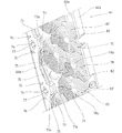
実施例に係るパチンコ機10は、図1に示すように、矩形枠状に形成されて遊技店の図示しない設置枠台に固定される固定枠としての外枠11の開口前面側に、後述する遊技盤17(図2参照)が着脱可能に保持された本体枠としての中枠12が開閉および着脱可能に組付けられて、該遊技盤17の裏側に対して、各種図柄を変動表示可能な図柄表示装置13が着脱し得るよう配設されている。前記中枠12の前面側には、前記遊技盤17を透視保護するガラス板を備えた装飾枠としての前枠14が開閉可能に組付けられている。この前枠14の下部位置に、パチンコ球を貯留する上球受け皿15が一体的に組付けられており、前枠14の開閉に合わせて上球受け皿15も一体的に開閉するよう構成される。また前記中枠12には、前記前枠14の下方にパチンコ球を貯留する下球受け皿16が開閉可能に組付けられている。
(About pachinko machines)
As shown in FIG. 1, the pachinko machine 10 according to the embodiment will be described later on the front side of the opening of the outer frame 11 as a fixed frame that is formed in a rectangular frame shape and fixed to an installation frame base (not shown) of the amusement store. A middle frame 12 as a body frame on which a game board 17 (see FIG. 2) is detachably held is assembled so as to be openable and detachable, and various symbols can be variably displayed on the back side of the game board 17. The symbol display device 13 is arranged to be detachable. On the front side of the middle frame 12, a front frame 14 as a decorative frame provided with a glass plate that protects the game board 17 from see-through is assembled so as to be openable and closable. An upper ball tray 15 for storing pachinko balls is integrally assembled at a lower position of the front frame 14, and the upper ball tray 15 is also configured to be opened and closed integrally with the opening and closing of the front frame 14. . A lower ball tray 16 for storing pachinko balls is assembled to the middle frame 12 so as to be openable and closable below the front frame 14.
(遊技盤について)
前記中枠12に配設される前記遊技盤17は、図2に示すように、前面(盤面)にパチンコ球が流下可能な遊技領域17aが画成され、アクリルやポリカーボネート等の光透過性の合成樹脂材からなる平板状の透明板で構成される。遊技盤17の前面には、円弧状に形成した案内レール18が配設されると共に、該案内レール18の右方位置に、左端縁が右方に凹む円弧状に形成した盤面飾り部材19が配設される。そして、案内レール18および盤面飾り部材19により遊技領域17aが略円形状に画成され、該遊技領域17a内に、中枠12に配設された図示しない打球発射装置から発射されたパチンコ球が打ち出され、該遊技領域17a内をパチンコ球が流下して遊技が行なわれる。また、遊技盤17の遊技領域17a内には、多数の遊技釘が植設されており、該遊技釘との接触により遊技領域17aを流下するパチンコ球の流下方向が不規則に変化するよう構成してある。
(About game board)
As shown in FIG. 2, the game board 17 disposed in the inner frame 12 has a game area 17a in which a pachinko ball can flow down on the front surface (board surface), and is made of a light-transmitting material such as acrylic or polycarbonate. It consists of a flat transparent plate made of a synthetic resin material. A guide rail 18 formed in an arc shape is disposed on the front surface of the game board 17, and a panel decoration member 19 formed in an arc shape whose left end edge is recessed rightward is provided at the right side of the guide rail 18. Arranged. Then, a game area 17a is defined in a substantially circular shape by the guide rail 18 and the board decoration member 19, and a pachinko ball launched from a ball striking device (not shown) disposed in the middle frame 12 is formed in the game area 17a. A game is played with a pachinko ball flowing down in the game area 17a. In addition, a large number of game nails are planted in the game area 17a of the game board 17, and the flow direction of the pachinko balls flowing down the game area 17a is irregularly changed by contact with the game nails. It is.
前記遊技盤17には、図1または図2に示す如く、後述する枠状装飾部材23の下縁より下方位置に、前記遊技領域17aを流下するパチンコ球が入賞可能な始動入賞装置20および特別入賞装置21等が配設される。始動入賞装置20は、遊技領域17aを流下するパチンコ球が入賞可能な始動入賞口が設けられる。そして、始動入賞装置20の始動入賞口へ入賞したパチンコ球が始動入賞センサ(図示せず)で検出されることで、図柄表示装置13の表示部13aで図柄変動が開始されると共に、所定数(例えば5個)のパチンコ球が賞球として前記上下の球受け皿15,16に払い出される。
As shown in FIG. 1 or FIG. 2, the game board 17 has a start prize device 20 and a special prize device that can win a pachinko ball flowing down the game area 17a below the lower edge of a frame-shaped decorative member 23 described later. A winning device 21 and the like are arranged. The start winning device 20 is provided with a start winning opening through which a pachinko ball flowing down the game area 17a can win. Then, a pachinko ball that has won a start winning opening of the start winning device 20 is detected by a start winning sensor (not shown), whereby the symbol variation is started on the display unit 13a of the symbol display device 13, and a predetermined number (For example, five) pachinko balls are paid out to the upper and lower ball trays 15 and 16 as prize balls.
前記特別入賞装置21は、入賞口が開閉扉で常には閉鎖されており、前記図柄表示装置13での図柄変動の結果、図柄表示装置13の表示部13aに所定の図柄組み合わせ(例えば同一図柄の三つ揃い等)で図柄が停止表示されることで所謂「大当り」が発生し、これにより開閉扉が開放するよう作動制御されて、入賞口への入賞により多数の賞球を獲得し得るようになっている。なお、図2の符号22は、遊技盤17に配設されて、常に入賞口を開放している普通入賞装置を示す。
The special winning device 21 has a winning opening that is always closed by an open / close door. As a result of the symbol variation in the symbol display device 13, a predetermined symbol combination (for example, the same symbol) is displayed on the display unit 13a of the symbol display device 13. When a symbol is stopped and displayed in a three-piece set, etc., a so-called `` big hit '' occurs, so that the door is opened and controlled so that a large number of prize balls can be obtained by winning a prize opening It has become. Note that reference numeral 22 in FIG. 2 indicates a normal winning device that is disposed on the game board 17 and always opens the winning opening.
(装飾部材について)
前記遊技盤17の中央には、図3に示す如く、前後に貫通する大型の貫通孔17bが形成されており、該貫通孔17bに対して前後に開口する枠状の枠状装飾部材(所謂センター役物)23が嵌め込まれるように着脱可能に配設される。そして、後述する設置部材28の開口部28aから臨む前記図柄表示装置13の表示部13aは、枠状装飾部材23における前後に開口する窓口(可視部)23aを介して遊技盤17の前側に露出して、該図柄表示装置13の表示部13aで展開される図柄変動演出を前側から視認し得るようになっている。
(About decorative members)
As shown in FIG. 3, a large through-hole 17b penetrating in the front-rear direction is formed in the center of the game board 17, and a frame-like frame-shaped decorative member (so-called so-called) that opens in the front-rear direction with respect to the through-hole 17b. Center accessory) 23 is detachably disposed so as to be fitted therein. And the display part 13a of the said symbol display apparatus 13 which faces from the opening part 28a of the installation member 28 mentioned later is exposed to the front side of the game board 17 via the window (visible part) 23a opened in the front and back in the frame-shaped decoration member 23. Thus, the symbol variation effect developed on the display unit 13a of the symbol display device 13 can be viewed from the front side.
前記枠状装飾部材23には、図1〜図3に示す如く、上縁部から左右両縁部に亘り、遊技盤17の前面より前方に突出する円弧状の庇状部23bが設けられており、前記遊技領域17aに打ち出されたパチンコ球を外周部の庇状部23bで案内し得ると共に、該パチンコ球が枠状装飾部材23の窓口23aを横切って流下するのを該庇状部23bで規制している。また枠状装飾部材23には、窓口23aの下側に、ステージ24が配設されると共に、窓口23aの左側に、遊技領域17aに開口して該遊技領域17aを流下するパチンコ球を取込んでステージ24に案内する球導入部25が設けられ、該球導入部25からステージ24に通出されたパチンコ球は、ステージ24上を左右に転動した後に、前記各入賞装置20,21,22が配設されている遊技領域17aに排出される。
As shown in FIGS. 1 to 3, the frame-shaped decorative member 23 is provided with an arc-shaped bowl-shaped portion 23 b that protrudes forward from the front surface of the game board 17 from the upper edge portion to the left and right edge portions. The pachinko ball launched into the game area 17a can be guided by the bowl-shaped portion 23b on the outer peripheral portion, and the pachinko ball 23b flows down across the window 23a of the frame-shaped decorative member 23. It is regulated by. The frame-shaped decorative member 23 is provided with a stage 24 on the lower side of the window 23a, and on the left side of the window 23a, takes a pachinko ball that opens into the game area 17a and flows down the game area 17a. The ball introduction part 25 for guiding to the stage 24 is provided, and the pachinko balls passed from the ball introduction part 25 to the stage 24 roll left and right on the stage 24, and then each of the winning devices 20, 21, The game area 17a in which 22 is disposed is discharged.
前記ステージ24の後端縁には、左右方向の全長に亘って上側に向けて所定高さで立上がる透明壁26が設けられ、ステージ24上を転動するパチンコ球が図柄表示装置13の表示部13a側に移動するのを該透明壁26で防止している。
The rear edge of the stage 24 is provided with a transparent wall 26 that rises at a predetermined height toward the upper side over the entire length in the left-right direction, and a pachinko ball that rolls on the stage 24 is displayed on the symbol display device 13. The transparent wall 26 prevents movement toward the portion 13a.
(設置部材について)
前記遊技盤17の裏面には、図3〜図7に示す如く、前記図柄表示装置13が着脱可能に配設されると共に、後述する可動演出装置M1,M2,M3や複数の発光装置144,145,146等の遊技部品が配設される合成樹脂材で形成された設置部材28が配設され、該設置部材28に形成された前後に開口する開口部28aを介して図柄表示装置13の表示部13aを遊技盤17の前側から視認し得るよう構成されている。実施例では、設置部材28の開口部28aは、上辺、下辺、左辺および右辺で画成される略4角形状に開口しており、図柄表示装置13の表示部13aは開口部28aから視認可能な領域となることから、該開口部28aの縁部が表示部13aの外縁となっている。
(About installation members)
As shown in FIGS. 3 to 7, the symbol display device 13 is detachably disposed on the back surface of the game board 17, and movable rendering devices M 1, M 2, M 3, which will be described later, and a plurality of light emitting devices 144, An installation member 28 made of a synthetic resin material on which gaming parts such as 145 and 146 are arranged is provided, and the symbol display device 13 is connected to the design display device 13 via an opening 28a formed in the installation member 28 and opening forward and backward. The display unit 13 a is configured to be visible from the front side of the game board 17. In the embodiment, the opening 28a of the installation member 28 is opened in a substantially square shape defined by the upper side, the lower side, the left side, and the right side, and the display unit 13a of the symbol display device 13 is visible from the opening 28a. Therefore, the edge portion of the opening 28a is the outer edge of the display portion 13a.
前記設置部材28は、図3〜図7に示すように、前方に開口する矩形箱状に形成された箱状本体29と、該箱状本体29の開口前端部に形成されて当該箱状本体29の開口外側へ延出し、前記遊技盤17の裏面に当接する取付部30とから構成される。箱状本体29は、遊技盤17に対向する矩形板状に形成された対向面壁31と、該対向面壁31における上下左右の各縁部から前方に延出する画壁32とから前方に開口するよう形成されて、各画壁32の前端部から箱状本体29の開口外側へ向けて延出するよう取付部30が形成される。そして、取付部30の前面を遊技盤17の裏面に当接した状態で、取付部30を遊技盤17にネジ止めすることによって遊技盤17に設置部材28が固定される。
As shown in FIGS. 3 to 7, the installation member 28 includes a box-shaped main body 29 formed in a rectangular box shape opening forward, and an opening front end portion of the box-shaped main body 29. 29, and the mounting portion 30 that extends to the outside of the opening 29 and abuts against the back surface of the game board 17. The box-shaped main body 29 opens forward from an opposing surface wall 31 formed in a rectangular plate shape facing the game board 17 and an image wall 32 extending forward from each of the upper, lower, left and right edges of the opposing surface wall 31. The attachment portion 30 is formed so as to extend from the front end portion of each drawing wall 32 toward the outside of the opening of the box-shaped main body 29. Then, the installation member 28 is fixed to the game board 17 by screwing the attachment part 30 to the game board 17 with the front surface of the attachment part 30 in contact with the back surface of the game board 17.
前記対向面壁31には、図7に示す如く、上下および左右幅の大部分が開口する大型の前記開口部28aが形成されている。以下の説明において、対向面壁31における開口部28aに対する上下左右に位置する部分について、上対向面壁31a、下対向面壁31b、左対向面壁31c、右対向面壁31dと夫々指称するものとする。
As shown in FIG. 7, the opposing surface wall 31 is formed with a large opening 28 a that opens most of the vertical and horizontal widths. In the following description, the portions of the opposing surface wall 31 that are positioned vertically and horizontally with respect to the opening 28a are referred to as an upper opposing surface wall 31a, a lower opposing surface wall 31b, a left opposing surface wall 31c, and a right opposing surface wall 31d, respectively.
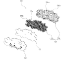
前記遊技盤17の裏側に設置部材28を取付けた状態で、該設置部材28の対向面壁31と遊技盤17との間に所要の設置空間Sが画成される。設置部材28の対向面壁31には、図4および図6に示す如く、左対向面壁31cおよび下対向面壁31bに第1可動演出装置M1が配設されると共に、右対向面壁31dおよび下対向面壁31bに第2可動演出装置M2が配設され、これら第1可動演出装置M1および第2可動演出装置M2は、遊技盤17の盤面に沿う方向で左右に離間している。また、上対向面壁31aに、第3可動演出装置M3が配設される。そして、これら3つの可動演出装置M1,M2,M3が、設置部材28と遊技盤17との間に画成される設置空間Sに夫々収容される。
With the installation member 28 attached to the back side of the game board 17, a required installation space S is defined between the facing wall 31 of the installation member 28 and the game board 17. 4 and 6, the first movable effect device M1 is disposed on the left facing surface wall 31c and the lower facing surface wall 31b on the facing surface wall 31 of the installation member 28, and the right facing surface wall 31d and the lower facing surface wall are disposed. A second movable effect device M2 is disposed at 31b, and the first movable effect device M1 and the second movable effect device M2 are separated from each other in the direction along the board surface of the game board 17. The third movable effect device M3 is disposed on the upper facing surface wall 31a. These three movable effect devices M 1, M 2, and M 3 are accommodated in an installation space S defined between the installation member 28 and the game board 17, respectively.
(第1可動演出装置について)
図4〜図9に示すように、前記第1可動演出装置M1は、前記設置部材28に取付けられる第1の本体をなす第1支持部材33と、該第1支持部材33に支持されて遊技盤17の盤面に沿って所要の動作を行ない得る第1の可動体34と、第1支持部材33の前側に配設されて第1の可動体34を駆動する第1の駆動手段としての第1モータ35とを備えている。第1の可動体34は、刀の刀身を模した長尺な形状に形成された第1装飾体部36と、該第1装飾体部36の長手方向の一端に設けられて前記第1支持部材33に揺動可能に支持される第1可動基部37とから構成される。第1支持部材33は、設置部材28の左対向面壁31cと下対向面壁31bとが交差する隅部(箱状本体29の下左隅部)に突設された複数の第1取付突部38の前端にネジ止め固定されて、該第1支持部材33に支持されている第1の可動体34は、通常時には設置部材28の左開口端に沿って上下方向に延在する姿勢(図4参照)となる待機位置に保持されている。前記第1取付突部38の前端位置は、第2可動演出装置M2を設置部材28に固定するための後述する第2取付突部90の前端位置より後方に位置し、該第1取付突部38の前端に第1支持部材33を固定した状態で、図6に示す如く、該第1支持部材33の裏面は対向面壁31に近接し、設置部材28の前側に取付けられる遊技盤17と第1支持部材33との間に、第1モータ35を収容可能な空間を確保し得るよう構成される。
(About the first movable effect device)
As shown in FIGS. 4 to 9, the first movable effect device M <b> 1 is a game that is supported by the first support member 33 that forms the first main body attached to the installation member 28, and the first support member 33. A first movable body 34 that can perform a required operation along the board surface of the board 17 and a first drive unit that is disposed on the front side of the first support member 33 and drives the first movable body 34. 1 motor 35. The first movable body 34 is provided with a first decorative body portion 36 formed in a long shape simulating the blade of a sword, and at one end in the longitudinal direction of the first decorative body portion 36, and the first support body 34. The first movable base 37 is supported by the member 33 so as to be swingable. The first support member 33 includes a plurality of first mounting projections 38 projecting from a corner (the lower left corner of the box-shaped main body 29) where the left facing surface wall 31c and the lower facing surface wall 31b of the installation member 28 intersect. The first movable body 34, which is fixed to the front end by screws and supported by the first support member 33, normally extends in the vertical direction along the left opening end of the installation member 28 (see FIG. 4). ) Is held at the standby position. The front end position of the first attachment protrusion 38 is located behind the front end position of the second attachment protrusion 90 described later for fixing the second movable effect device M2 to the installation member 28, and the first attachment protrusion With the first support member 33 fixed to the front end of 38, the back surface of the first support member 33 is close to the facing surface wall 31 and the game board 17 attached to the front side of the installation member 28 and the first board as shown in FIG. It is comprised so that the space which can accommodate the 1st motor 35 between the 1 support members 33 can be ensured.
実施例では、図1に示すように、前記第1の可動体34が待機位置にある状態において、該第1の可動体34の前側に前記遊技盤17および枠状装飾部材23が位置するよう構成されており、該枠状装飾部材23で第1の可動体34の右側部分が覆われている。なお、待機位置の第1の可動体34と遊技盤17との間には、後述する左発光装置144が位置して、該左発光装置144により第1の可動体34の左側部分が覆われるようになっている(図6参照)。また第1の可動体34は、後述する作動位置において前記窓口23aの対応する左端縁部から図柄表示装置13における表示部13aの略中央まで延出する大型のものであって(図2,図5参照)、待機位置と作動位置との間を、前記設置空間Sにおける設置部材28の対向面壁31側に偏倚した第1の移動領域を遊技盤17の盤面に沿って移動するよう構成される。実施例では、設置空間Sの前後方向の中間より後側を第1の可動体34が移動するようになっている。
In the embodiment, as shown in FIG. 1, the game board 17 and the frame-shaped decorative member 23 are positioned on the front side of the first movable body 34 in a state where the first movable body 34 is in the standby position. The right side portion of the first movable body 34 is covered with the frame-shaped decorative member 23. Note that a left light-emitting device 144 described later is positioned between the first movable body 34 and the game board 17 at the standby position, and the left light-emitting device 144 covers the left side portion of the first movable body 34. (See FIG. 6). The first movable body 34 is a large one that extends from the corresponding left end edge of the window 23a to the approximate center of the display portion 13a in the symbol display device 13 in the operating position described later (FIGS. 2 and 2). 5), and is configured to move along the board surface of the game board 17 between the standby position and the operating position in a first movement area biased toward the opposing surface wall 31 of the installation member 28 in the installation space S. . In the embodiment, the first movable body 34 moves behind the middle of the installation space S in the front-rear direction.
(第1支持部材について)
図6、図9〜図11に示す如く、前記第1支持部材33は、前記設置部材28の対向面壁31(箱状本体29の下左隅部)に取付けられる第1取付ベース体39と、該第1取付ベース体39の前面に取付けられる第1カバー体40とから構成される。第1取付ベース体39は、平板状に形成された後板39aの外周縁部に前方に向けて側壁39bを突設した前方に開口する箱状に形成される。また第1カバー体40は、平板状に形成された前板40aの外周縁部に、後方に向けて側壁40bが突設されている。そして、第1取付ベース体39と第1カバー体40とを、後板39aおよび前板40aを対向して両側壁39b,40bの端部を当接するように組付けることで、第1取付ベース体39と第1カバー体40との間に第1収容空間S1が画成されるようになっている(図6,図11参照)。なお、第1取付ベース体39および第1カバー体40は、何れも合成樹脂材から形成されている。
(About the first support member)
As shown in FIGS. 6 and 9 to 11, the first support member 33 includes a first attachment base body 39 attached to the facing surface wall 31 (the lower left corner of the box-shaped main body 29) of the installation member 28, and The first cover body 40 is attached to the front surface of the first attachment base body 39. The first mounting base body 39 is formed in a box shape that opens to the front with a side wall 39b projecting forward from the outer peripheral edge portion of the rear plate 39a formed in a flat plate shape. Further, the first cover body 40 has a side wall 40b projecting rearward from the outer peripheral edge portion of the front plate 40a formed in a flat plate shape. Then, the first mounting base body 39 and the first cover body 40 are assembled so that the rear plate 39a and the front plate 40a face each other so that the end portions of both side walls 39b and 40b are in contact with each other. A first housing space S1 is defined between the body 39 and the first cover body 40 (see FIGS. 6 and 11). The first mounting base body 39 and the first cover body 40 are both formed from a synthetic resin material.
(第1取付ベース体について)
前記第1取付ベース体39における後板39aの裏面には、図8〜図10に示すように、平板状の第1補強板金41が複数のネジを介してネジ止め固定されると共に、該第1補強板金41に配設されて前方に突出する第1支持軸41aが、後板39aに形成した中心通孔39cに挿通されて前記第1収容空間S1に臨んでいる。そして、前記第1の可動体34の第1可動基部37に形成されて前後に貫通する軸孔53aに第1支持軸41aを挿通することで、該第1の可動体34が第1取付ベース体39(第1支持部材33)に対して前後方向に沿う第1支持軸41a(回転軸)を中心として左右方向に揺動可能に支持される。なお、前記中心通孔39cは、第1支持軸41aの直径より大きな内径に設定されて、前記第1の可動体34の第1可動基部37に形成された後述する支持突部37cの挿入を許容するようになっている。また、第1取付べース体39の側壁39bは、図9に示すように、後板39aの上側において所定長さに亘って切欠かれており、この切欠部39dにおいて前記第1支持部材33の第1収容空間S1は外部に開口し、この切欠部39dから第1の可動体34の後述する固定部55が外部に延出するよう構成される。なお、第1支持部材33には、切欠部39dの左端に対応する位置に、第1の可動体34に配設した後述する磁石58が磁力吸着することで該第1の可動体34を待機位置に保持するべく機能する金属体42が配設されている。
(About the first mounting base)
On the back surface of the rear plate 39a in the first mounting base 39, as shown in FIGS. 8 to 10, a flat plate-like first reinforcing metal plate 41 is screwed and fixed via a plurality of screws. A first support shaft 41a, which is disposed on one reinforcing sheet metal 41 and protrudes forward, is inserted through a central through hole 39c formed in the rear plate 39a and faces the first accommodation space S1. Then, by inserting the first support shaft 41a through the shaft hole 53a formed in the first movable base portion 37 of the first movable body 34 and penetrating in the front-rear direction, the first movable body 34 becomes the first mounting base. The body 39 (first support member 33) is supported so as to be swingable in the left-right direction about a first support shaft 41a (rotary shaft) along the front-rear direction. The central through-hole 39c is set to have an inner diameter larger than the diameter of the first support shaft 41a, and a later-described support protrusion 37c formed on the first movable base 37 of the first movable body 34 is inserted. It comes to allow. Further, as shown in FIG. 9, the side wall 39b of the first mounting base body 39 is notched over a predetermined length on the upper side of the rear plate 39a, and the first support member 33 is formed at the notch 39d. The first housing space S1 is open to the outside, and a fixing portion 55 (to be described later) of the first movable body 34 extends from the cutout portion 39d to the outside. Note that a magnet 58 (described later) disposed on the first movable body 34 is magnetically attracted to the first support member 33 at a position corresponding to the left end of the notch 39d so that the first movable body 34 is on standby. A metal body 42 is provided that functions to hold in position.
前記第1取付べース体39における後板39aの前面には、図9に示す如く、前記中心通孔39cを中心とする所定直径で環状の補強リブ43が突設されると共に、該補強リブ43には後受部44が周方向に等間隔で設けられている。実施例では、周方向に90°の角度間隔で4つの後受部44が設けられる。各後受部44には、図12(a)に示す如く、前側に開口する凹部44aが形成されて、該凹部44aに前側から後球体(転動体)45が転動自在に遊嵌されて、該後球体45の後受部44から前方に突出する部分が前記第1可動基部37の裏面に転動自在に接触するよう構成される。なお、後球体45としては、該後球体45が接触する第1可動基部37より硬い材質のものが好適に使用され、実施例ではステンレス製の球体が用いられる。また、前記第1取付ベース体39における後板39aには、前記補強リブ43と中心通孔39cとの間に、周方向に離間する一対の片部からなるバネ用係止部46が前方に向けて突設され、該バネ用係止部46に後述する第1捻りコイルバネ57の一方の係合片が係止するよう構成される。
As shown in FIG. 9, an annular reinforcing rib 43 having a predetermined diameter centered on the central through hole 39c is projected on the front surface of the rear plate 39a of the first mounting base body 39, and the reinforcing plate The ribs 43 are provided with rear receiving portions 44 at equal intervals in the circumferential direction. In the embodiment, four rear receiving portions 44 are provided at an angular interval of 90 ° in the circumferential direction. As shown in FIG. 12A, each rear receiving portion 44 is formed with a concave portion 44a that opens to the front side, and a rear sphere (rolling body) 45 is loosely fitted to the concave portion 44a from the front side. The portion projecting forward from the rear receiving portion 44 of the rear sphere 45 is configured to contact the back surface of the first movable base portion 37 in a rollable manner. The rear sphere 45 is preferably made of a material harder than the first movable base 37 with which the rear sphere 45 contacts. In the embodiment, a stainless sphere is used. In addition, the rear plate 39a of the first mounting base body 39 has a spring locking portion 46 formed of a pair of pieces spaced apart in the circumferential direction between the reinforcing rib 43 and the central through hole 39c. The first engaging coil spring 57, which will be described later, is engaged with the spring engaging portion 46 so as to be engaged therewith.
前記第1取付ベース体39の下部には、下側の側壁39bの前端から下方に向けて後板39aと平行に延在するモータ設置部47が形成される。モータ設置部47の前面に、前記第1の可動体34を揺動させる前記第1モータ35が、出力軸を後方に向けて前側から配設され、該モータ35におけるモータ設置部47の裏側に延出する出力軸に、板状の第1駆動歯車48が配設される。なお、モータ設置部47の形成位置に対応する下側の側壁39bの一部が切欠かれ、この切欠き部分から前記第1駆動歯車48の一部が前記第1収容空間S1に臨むよう構成される(図11参照)。図8〜図11において符号49は、モータ設置部47の裏側に配設されて、前記第1駆動歯車48を回転自在に支持する支持板を示す。
A motor installation portion 47 is formed at a lower portion of the first mounting base body 39. The motor installation portion 47 extends in parallel with the rear plate 39a from the front end of the lower side wall 39b downward. The first motor 35 for swinging the first movable body 34 is disposed on the front surface of the motor installation portion 47 from the front side with the output shaft directed rearward, and on the back side of the motor installation portion 47 in the motor 35. A plate-like first drive gear 48 is disposed on the extending output shaft. A part of the lower side wall 39b corresponding to the position where the motor installation portion 47 is formed is cut out, and a part of the first drive gear 48 faces the first housing space S1 from the cutout part. (See FIG. 11). 8 to 11, reference numeral 49 indicates a support plate that is disposed on the back side of the motor installation portion 47 and rotatably supports the first drive gear 48.
前記第1取付ベース体39の下端部における前記第1モータ35の配設位置に隣接する部位には、前記第1の可動体34の揺動位置を検出する第1位置検出センサ50が取付けられている。この第1位置検出センサ50として、実施例では受光素子と発光素子とを備えた光学式センサを採用しているが、これに限らず、磁気センサやマイクロスイッチ、その他従来公知のセンサを第1の可動体34側に設けられる被検出部(後述)に応じて採用することができる。
A first position detection sensor 50 for detecting the swinging position of the first movable body 34 is attached to a portion of the lower end portion of the first attachment base body 39 adjacent to the position where the first motor 35 is disposed. ing. As the first position detection sensor 50, an optical sensor provided with a light receiving element and a light emitting element is employed in the embodiment. It can be employed according to a detected part (described later) provided on the movable body 34 side.
前記第1取付ベース体39の側壁39bには、前記第1モータ35の配設位置を挟んで周方向に離間する2箇所に、内側(第1収容空間S1側)に突出するストッパ51a,51bが設けられている。これらストッパ51a,51bは、第1支持部材33に対して第1の可動体34が揺動された際に、第1可動基部37に設けた後述する歯車部37dの周方向の端部が各ストッパ51a,51bに当接することで第1の可動体34の揺動範囲を制限するようになっている。なお、以下の説明では、右側に位置するストッパ51aを第1ストッパと指称し、左側に位置するストッパ51bを第2ストッパと指称する。
On the side wall 39b of the first mounting base body 39, stoppers 51a and 51b projecting inwardly (on the side of the first housing space S1) at two locations spaced in the circumferential direction across the position where the first motor 35 is disposed. Is provided. When the first movable body 34 is swung with respect to the first support member 33, the stoppers 51 a and 51 b have circumferential end portions of a gear portion 37 d provided on the first movable base portion 37, which will be described later. The swing range of the first movable body 34 is limited by contacting the stoppers 51a and 51b. In the following description, the stopper 51a located on the right side is referred to as a first stopper, and the stopper 51b located on the left side is referred to as a second stopper.
前記第1取付ベース体39には、図9、図13、図14に示す如く、前記第1モータ35および第1位置検出センサ50の配設位置に近接してベース側配線止め部52が設けられる。そして、前記第1位置検出センサ50から導出する配線、第1モータ35から導出する配線、および前記第1の可動体34の後述する第1LED基板65から導出する第1配線H1が、纏められた状態でベース側配線止め部52に結束具52aを介して係止されて、これらの配線H1が第1支持部材33の前方へ大きく変位するのを防止するよう構成されている(図14参照)。
As shown in FIGS. 9, 13, and 14, the first attachment base body 39 is provided with a base-side wiring stopper 52 in the vicinity of the positions where the first motor 35 and the first position detection sensor 50 are disposed. It is done. Then, the wiring derived from the first position detection sensor 50, the wiring derived from the first motor 35, and the first wiring H1 derived from the first LED board 65 described later of the first movable body 34 are collected. In this state, it is locked to the base-side wiring stopper 52 via a binding tool 52a to prevent the wiring H1 from being largely displaced forward of the first support member 33 (see FIG. 14). .
(第1カバー体について)
前記第1カバー体40の前板40aは、図11に示す如く、前記第1取付ベース体39におけるモータ設置部47の上側の開口部分を覆い得る寸法および形状に形成されており、第1取付ベース体39の前側に第1カバー体40をネジ止め固定した状態で、モータ設置部47に配設した第1モータ35が第1カバー体40より前側に延出するよう構成される。また、第1カバー体40の側壁40bは、前記第1取付ベース体39の側壁39bを切欠くことで形成した前記切欠部39dに対応する部位が切欠かれており、前記第1の可動体34の固定部55が外方に延出するのを許容すると共に、該固定部55(第1の可動体34)の左右方向への移動を許容し得る寸法の隙間を確保し得るようになっている。
(About the first cover body)
As shown in FIG. 11, the front plate 40 a of the first cover body 40 is formed in a size and shape that can cover the upper opening portion of the motor installation portion 47 in the first mounting base body 39. In a state where the first cover body 40 is screwed and fixed to the front side of the base body 39, the first motor 35 disposed in the motor installation portion 47 is configured to extend forward from the first cover body 40. Further, the side wall 40b of the first cover body 40 is cut out at a portion corresponding to the cutout portion 39d formed by cutting out the side wall 39b of the first mounting base body 39, and the first movable body 34 is cut. The fixing portion 55 is allowed to extend outward, and a gap having a dimension that allows the fixing portion 55 (the first movable body 34) to move in the left-right direction can be secured. Yes.
前記第1カバー体40における前板40aの裏面(第1収容空間S1側の面)には、図10および図11に示す如く、前記第1の可動体34の軸孔53aに挿通されて前側に突出する前記第1支持軸41aの先端を支持する左第1軸受部40cが形成してある。また前板40aの裏面には、左第1軸受部40cを囲繞する筒状で後方に開口する左第2軸受部40dが所要長さで突設され、該左第2軸受部40dには、第1の可動体34の軸孔53aが形成される後述する軸支部53の前端が回動自在に挿入されるようになっている。
As shown in FIGS. 10 and 11, the back surface of the front plate 40a in the first cover body 40 (the surface on the first housing space S1 side) is inserted through the shaft hole 53a of the first movable body 34 and is front side. A left first bearing portion 40c is formed to support the tip of the first support shaft 41a projecting to the left. Further, on the back surface of the front plate 40a, a left second bearing portion 40d that is a cylindrical shape that surrounds the left first bearing portion 40c and that opens rearward is projected in a required length, and the left second bearing portion 40d includes: A front end of a later-described shaft support portion 53 in which a shaft hole 53a of the first movable body 34 is formed is rotatably inserted.
前記第1カバー体40における前板40aの裏面に、図10に示す如く、前記左第1軸受部40cを中心として所要直径で環状の第1の突条部40eが突設され、該突条部40eに、図12(b)に示す如く、前記第1の可動体34における第1可動基部37に設けた後述する前球体61が転動自在に接触するよう構成される。実施例では、第1の突条部40eは、前記第1取付ベース体39の補強リブ43と同一直径で形成されて、第1の突条部40eは、第1可動基部37を挟んで補強リブ43上に設けた前記各後受部44に遊嵌されている後球体45の前方に臨むようになっている。また、第1カバー体40の前板40aには、図10に示す如く、前記第1の突条部40eと左第2軸受部40dとの間に、前後方向に貫通する配線口40fが周方向に所要長さで形成されており、該配線口40fを介して後述する第1配線H1が第1支持部材33の外部に引き出されるようになっている(図14参照)。
As shown in FIG. 10, an annular first protrusion 40e having a required diameter centering on the left first bearing part 40c is provided on the back surface of the front plate 40a of the first cover body 40. As shown in FIG. 12 (b), a front sphere 61 (described later) provided on the first movable base 37 of the first movable body 34 is configured to come into contact with the portion 40e so as to be able to roll. In the embodiment, the first protrusion 40 e is formed with the same diameter as the reinforcing rib 43 of the first mounting base body 39, and the first protrusion 40 e is reinforced with the first movable base 37 interposed therebetween. It faces the front of the rear sphere 45 that is loosely fitted to each rear receiving portion 44 provided on the rib 43. Further, as shown in FIG. 10, the front plate 40a of the first cover body 40 has a wiring port 40f penetrating in the front-rear direction between the first protrusion 40e and the left second bearing portion 40d. The first wiring H1, which will be described later, is drawn out to the outside of the first support member 33 through the wiring port 40f (see FIG. 14).
(第1の可動体について)
図9または図10に示すように、前記第1の可動体34は、前記第1支持部材33に対して第1取付ベース体39の後板39aおよび第1カバー体40の前板40aとの対向方向と交差する方向に回動自在に枢支される前記第1可動基部37と、該第1可動基部37に第1支持部材33の外部で取付けられた前記第1装飾体部36とから構成される。そして、前記第1支持部材33に配設された前記第1モータ35を正逆方向に駆動することで、第1の可動体34は前記第1支持軸41aを中心として揺動するよう構成されている。なお、第1の可動体34における第1装飾体部36は後述する第1LED基板65を備え、該第1LED基板65に配設したLED72,81の発光により発光演出を行ない得るよう構成されており、第1可動演出装置M1は、発光により演出を行なう演出装置としても機能する。
(About the first movable body)
As shown in FIG. 9 or 10, the first movable body 34 is connected to the rear plate 39 a of the first mounting base body 39 and the front plate 40 a of the first cover body 40 with respect to the first support member 33. From the first movable base portion 37 pivotally supported in a direction crossing the facing direction, and the first decorative body portion 36 attached to the first movable base portion 37 outside the first support member 33. Composed. The first movable body 34 is configured to swing around the first support shaft 41a by driving the first motor 35 disposed on the first support member 33 in the forward and reverse directions. ing. The first decorative body portion 36 of the first movable body 34 includes a first LED board 65 which will be described later, and is configured to perform a light emission effect by light emission of the LEDs 72 and 81 disposed on the first LED board 65. The first movable effect device M1 also functions as an effect device that produces an effect by light emission.
(第1可動基部について)
前記第1可動基部37は、図9〜図13に示すように、略円盤状に形成された本体部37aにおける外周縁部に、前方および後方に向けて突出する側壁37bが設けられている。本体部37aの略中央には、壁を凹ませることで後方に向けて突出する支持突部37cが設けられると共に、該支持突部37cの中心から前方に向けて筒状の軸支部53が突設され、該軸支部53に穿設された前後に貫通する軸孔53aに、前記第1支持軸41aが回動自在に挿通される。すなわち、第1可動基部37は、軸支部53の軸孔53aに挿通された第1支持軸41aを中心として回動可能に第1支持部材33に支持される。また、図11に示す如く、本体部37aの支持突部37cが、第1取付ベース体39の前記中心通孔39cに回動自在に挿入されると共に、軸支部53の前端が、第1カバー体40の左第2軸受部40dに回動自在に挿入されることで、第1支持部材33に対して第1可動基部37を安定して回動自在に支持するよう構成される。
(About the first movable base)
As shown in FIGS. 9 to 13, the first movable base portion 37 is provided with a side wall 37 b that protrudes forward and rearward at an outer peripheral edge portion of a main body portion 37 a formed in a substantially disc shape. A support protrusion 37c that protrudes rearward by denting the wall is provided at the approximate center of the main body 37a, and a cylindrical shaft support 53 protrudes forward from the center of the support protrusion 37c. The first support shaft 41a is rotatably inserted into a shaft hole 53a that is provided and penetrates the shaft support 53 in the front-rear direction. That is, the first movable base portion 37 is supported by the first support member 33 so as to be rotatable about the first support shaft 41 a inserted through the shaft hole 53 a of the shaft support portion 53. Further, as shown in FIG. 11, the support protrusion 37c of the main body portion 37a is rotatably inserted into the central through hole 39c of the first mounting base body 39, and the front end of the shaft support portion 53 is connected to the first cover. By being rotatably inserted into the left second bearing portion 40d of the body 40, the first movable base portion 37 is configured to be stably and rotatably supported with respect to the first support member 33.
前記軸支部53は、支持突部37cより小径に設定されて、支持突部37cの前側に画成される凹部の内側と軸支部53との間には略筒状の溝部54が形成されるようになっている。また軸支部53は、前記側壁37bより前方に突出する寸法に設定される。そして、第1取付べース体39に第1カバー体40を組付けた状態で、図11に示す如く、軸支部53の前端が前記左第2軸受部40dに挿入されると共に、該左第2軸受部40dの後端が、前記溝部54内に臨むよう構成される。
The shaft support 53 is set to have a smaller diameter than the support protrusion 37c, and a substantially cylindrical groove portion 54 is formed between the inside of the recess defined on the front side of the support protrusion 37c and the shaft support 53. It is like that. Moreover, the axial support part 53 is set to the dimension which protrudes ahead from the said side wall 37b. Then, with the first cover body 40 assembled to the first mounting base body 39, the front end of the shaft support portion 53 is inserted into the left second bearing portion 40d as shown in FIG. The rear end of the second bearing portion 40d is configured to face the groove portion 54.
前記第1可動基部37の外周縁には、第1の可動体34の待機位置において、前記第1支持軸41aの上方に臨む位置に、径方向に延出する固定部55が設けられ、該固定部55が第1支持部材33の前記切欠部39dから外方に延出している(図8参照)。前記第1可動基部37の本体部37aには、図9に示す如く、軸孔53aを挟んで固定部55とは略反対側(待機位置において下側)に、径方向外方に延出する歯車部37dが所要中心角で設けられている。そして、歯車部37dは、第1可動基部37を第1支持部材33に配設した状態で、前記第1ストッパ51aと第2ストッパ51bとの間に位置すると共に、前記第1駆動歯車48に噛合している(図13参照)。すなわち、前記第1モータ35を駆動して第1駆動歯車48を正転および逆転方向に回転することで、第1可動基部37(第1の可動体34)は、前記第1支持軸41aを中心として左右方向に揺動する。実施例では、歯車部37dを備えた第1可動基部37が、板状の可動ギヤとして機能する。また、第1の可動体34の前記待機位置において歯車部37dにおける周方向の一端が第1ストッパ51aに当接することで第1の可動体34の揺動が規制されており、該待機位置から第1の可動体34が右方向に傾倒するよう揺動して歯車部37dにおける周方向の他端が第2ストッパ51bに当接することで、第1の可動体34の揺動が規制されるようになっている。なお、以下の説明では、歯車部37dが第2ストッパ51bに当接して第1の可動体34の揺動が規制される位置を作動位置(図5,図15(b)参照)と指称する。すなわち、第1の可動体34は待機位置と作動位置との間で揺動される。
The outer peripheral edge of the first movable base portion 37 is provided with a fixing portion 55 extending in the radial direction at a position facing the upper side of the first support shaft 41a at the standby position of the first movable body 34. The fixing portion 55 extends outward from the cutout portion 39d of the first support member 33 (see FIG. 8). As shown in FIG. 9, the main body portion 37a of the first movable base portion 37 extends radially outwardly on the opposite side of the fixing portion 55 (lower side in the standby position) across the shaft hole 53a. A gear portion 37d is provided at a required central angle. The gear portion 37d is positioned between the first stopper 51a and the second stopper 51b in a state where the first movable base portion 37 is disposed on the first support member 33, and is connected to the first drive gear 48. They are engaged (see FIG. 13). That is, by driving the first motor 35 and rotating the first drive gear 48 in the forward and reverse directions, the first movable base portion 37 (first movable body 34) moves the first support shaft 41a. It swings in the left-right direction as the center. In the embodiment, the first movable base portion 37 provided with the gear portion 37d functions as a plate-like movable gear. Further, at the standby position of the first movable body 34, one end in the circumferential direction of the gear portion 37d abuts on the first stopper 51a, so that the swinging of the first movable body 34 is restricted, and from the standby position. The first movable body 34 swings so as to tilt rightward, and the other end in the circumferential direction of the gear portion 37d contacts the second stopper 51b, whereby the swing of the first movable body 34 is restricted. It is like that. In the following description, a position where the gear portion 37d contacts the second stopper 51b and the swing of the first movable body 34 is restricted is referred to as an operating position (see FIGS. 5 and 15B). . That is, the first movable body 34 is swung between the standby position and the operating position.
前記第1可動基部37における本体部37aには、図13に示す如く、前記軸支部53を囲う溝部54に連通すると共に前後方向に貫通する扇形の通孔37eが形成されており、該通孔37e内に、前記第1取付ベース体39に設けた前記バネ用係止部46が臨んでいる。また、本体部37aの前面には、溝部54および通孔37eの内周縁から前方に突出するように画壁部56が突設されると共に、該画壁部56には、通孔37eの形成位置から周方向に離間する所要位置に、溝部54に連通するバネ用係止部56aが凹設されている。そして、コイル部に軸支部53が挿通されるように配設した第1捻りコイルバネ57の一方の係合片が、第1取付ベース体39のバネ用係止部46に係止されると共に、該第1捻りコイルバネ57の他方の係合片が、画壁部56のバネ用係止部56aに係止されており、第1の可動体34は、第1捻りコイルバネ57によって常には待機位置に向けて付勢されるようになっている。また、第1可動基部37には、前記固定部55の左端部に磁石58が配設され、第1の可動体34の待機位置において、該磁石58が第1取付ベース体39に配設した前記金属体42を磁力吸着するよう構成してある。
As shown in FIG. 13, the main body portion 37a of the first movable base portion 37 is formed with a fan-shaped through hole 37e communicating with the groove portion 54 surrounding the shaft support portion 53 and penetrating in the front-rear direction. 37e faces the spring locking portion 46 provided on the first mounting base body 39. An image wall 56 projects from the front surface of the main body 37a so as to protrude forward from the inner periphery of the groove 54 and the through hole 37e, and a through hole 37e is formed in the image wall 56. A spring locking portion 56a that communicates with the groove portion 54 is recessed at a required position that is separated from the position in the circumferential direction. Then, one engaging piece of the first torsion coil spring 57 disposed so that the shaft support portion 53 is inserted into the coil portion is locked to the spring locking portion 46 of the first mounting base body 39, and The other engagement piece of the first torsion coil spring 57 is engaged with the spring engagement portion 56 a of the image wall portion 56, and the first movable body 34 is always in the standby position by the first torsion coil spring 57. It has come to be urged towards. In the first movable base 37, a magnet 58 is disposed at the left end of the fixed portion 55, and the magnet 58 is disposed on the first mounting base body 39 at the standby position of the first movable body 34. The metal body 42 is configured to be magnetically adsorbed.
なお、前記第1取付ベース体39に第1カバー体40を組付けた状態で、図11に示す如く、前記左第2軸受部40dの後端が画壁部56の内側において溝部54内に臨み、該左第2軸受部40dで第1捻りコイルバネ57の前方への移動を規制し得るようになっている。
In the state where the first cover body 40 is assembled to the first mounting base body 39, the rear end of the left second bearing portion 40d is in the groove portion 54 inside the painting wall portion 56 as shown in FIG. In front, the left second bearing portion 40d can regulate the forward movement of the first torsion coil spring 57.
前記第1可動基部37の本体部37aにおける裏面(他方の面)に、前記第1取付ベース体39に設けた前記補強リブ43と対向する位置に環状の第2の突条部59が突設され、該突条部59に、前記後受部44に遊嵌されている後球体45が転動自在に接触するよう構成される(図12(a)参照)。また、本体部37aにおける前面(一方の面)には、図9に示す如く、外周縁部近傍に、前側に突出する前受部60が周方向に等間隔で複数設けられている。実施例では、前記軸孔53aを中心として前記後球体45が位置する補強リブ43に前後で整合する仮想円の周上において周方向に90°の角度間隔で4つの前受部60が設けられる。各前受部60には、前側に開口する凹部60aが設けられ、各凹部60aに前側から前球体(転動体)61が転動自在に遊嵌される。そして、前球体61の前受部60から前方に突出する部分が、図12(b)に示す如く、前記第1カバー体40の前記第1の突条部40eに転動自在に接触するよう構成される。すなわち、第1可動基部37の本体部37aは、前後両側で夫々複数の球体45,61により回動自在に支持されて、前記第1支持軸41aを中心に第1可動基部37が揺動する際には、後球体45および前球体61に接触した状態で安定して揺動するよう構成されている。なお、前球体61としては、該前球体61が接触する第1カバー体40より硬い材質のものが好適に使用され、実施例ではステンレス製の球体が用いられる。
On the back surface (the other surface) of the main body portion 37a of the first movable base portion 37, an annular second ridge portion 59 protrudes at a position facing the reinforcing rib 43 provided on the first mounting base body 39. Then, the rear sphere 45 loosely fitted to the rear receiving portion 44 is configured to come into contact with the protrusion 59 so as to be able to roll (see FIG. 12A). Further, on the front surface (one surface) of the main body portion 37a, as shown in FIG. 9, a plurality of front receiving portions 60 protruding forward are provided at equal intervals in the circumferential direction in the vicinity of the outer peripheral edge portion. In the embodiment, four front receiving portions 60 are provided at an angular interval of 90 ° in the circumferential direction on the circumference of an imaginary circle aligned with the reinforcing rib 43 where the rear sphere 45 is located around the shaft hole 53a. . Each front receiving portion 60 is provided with a recessed portion 60a that opens to the front side, and a front sphere (rolling body) 61 is loosely fitted to each recessed portion 60a from the front side. And the part which protrudes ahead from the front receiving part 60 of the front sphere body 61 contacts the said 1st protrusion 40e of the said 1st cover body 40 so that rolling is possible, as shown in FIG.12 (b). Composed. That is, the main body portion 37a of the first movable base portion 37 is rotatably supported by a plurality of spheres 45 and 61 on both the front and rear sides, and the first movable base portion 37 swings around the first support shaft 41a. At this time, the rear sphere 45 and the front sphere 61 are configured to swing stably in contact with the rear sphere 45 and the front sphere 61. The front sphere 61 is preferably made of a material harder than the first cover body 40 with which the front sphere 61 contacts, and in the embodiment, a stainless sphere is used.
前記第1の可動体34の待機位置において第1可動基部37の裏面に接触する各後球体45は、図13に示す如く、該第1可動基部37の前面に配設されて周方向(第1の可動体34の移動方向)に隣り合う前球体61,61の中間に臨むように設定される。すなわち、後球体45および前球体61は、夫々4つ球体が周方向に90°の角度間隔で配置されているから、待機位置における正面視において、前球体61と周方向に隣り合う後球体45とは45°の角度間隔で臨むようになっている。
Each rear sphere 45 that contacts the back surface of the first movable base 37 at the standby position of the first movable body 34 is disposed on the front surface of the first movable base 37 as shown in FIG. It is set so as to face the middle of the front spheres 61 and 61 adjacent to each other in the moving direction of one movable body 34). That is, since the four spheres of the rear sphere 45 and the front sphere 61 are arranged at an angular interval of 90 ° in the circumferential direction, the rear sphere 45 adjacent to the front sphere 61 in the circumferential direction when viewed from the front at the standby position. It faces at an angle interval of 45 °.
前記第1可動基部37の前記歯車部37dには、径方向外方に延出する前記被検出部としての位置検出片62が形成されている。位置検出片62は、前記第1位置検出センサ50の発光素子と受光素子との間に臨み得る位置に設けられており、前記第1可動基部37の揺動に伴って該発光素子と受光素子との間を位置検出片62が移動し得るようになっている。そして、位置検出片62を第1位置検出センサ50で検出した際に、前記待機位置に第1の可動体34が位置(図13参照)するよう設定されている。実施例では、第1位置検出センサ50が位置検出片62を検出した位置(待機位置)を基準として、第1の可動体34を右方に所定角度移動するように、図示しない制御手段で第1モータ35を駆動制御することで、該第1の可動体34を作動位置に位置させるよう構成してある。なお、歯車部37dに2つの位置検出片を周方向に離間して形成し、第1位置検出センサ50で一方の位置検出片を検出する位置を待機位置、他方の位置検出片を検出する位置を作動位置として、第1位置検出センサ50による各位置検出片の検出に基づいて制御手段が第1モータ35を駆動制御する構成としてもよい。
A position detection piece 62 is formed on the gear portion 37d of the first movable base portion 37 as the detected portion extending outward in the radial direction. The position detection piece 62 is provided at a position that can face between the light emitting element and the light receiving element of the first position detection sensor 50, and the light emitting element and the light receiving element are moved along with the swing of the first movable base 37. The position detection piece 62 can move between the two. When the position detection piece 62 is detected by the first position detection sensor 50, the first movable body 34 is set at the standby position (see FIG. 13). In the embodiment, the first movable body 34 is moved to the right by a predetermined angle on the basis of the position (standby position) where the first position detection sensor 50 has detected the position detection piece 62 as a reference. By driving and controlling one motor 35, the first movable body 34 is positioned at the operating position. Two position detection pieces are formed in the gear portion 37d so as to be separated from each other in the circumferential direction, and the position where one position detection piece is detected by the first position detection sensor 50 is a standby position, and the position where the other position detection piece is detected. The control means may drive the first motor 35 based on the detection of each position detection piece by the first position detection sensor 50.
前記第1可動基部37における本体部37aの前面には、図13、図14、図15に示す如く、前記固定部55の形成位置から軸孔側に向けて延在する一対の案内壁63,63が、所定間隔離間して平行に突設されている。両案内壁63,63の間の本体部37aは後側に向けて凹設されると共に、両案内壁63,63の径方向外側は開口し、前記第1装飾体部36に設けた後述する第1LED基板65から導出する第1配線H1を第1収容空間S1内において引き回す経路を、両案内壁63,63間に確保するよう構成される。また、前記第1カバー体40に形成された前記配線口40fは、両案内壁63,63における画壁部56側の端部前側に位置し、両案内壁63,63の間を引き回された第1配線H1が配線口40fから外部に引き出されるようになっている。
On the front surface of the main body 37a of the first movable base 37, as shown in FIGS. 13, 14, and 15, a pair of guide walls 63 extending from the formation position of the fixing portion 55 toward the shaft hole side, 63 protrudes in parallel with a predetermined interval. A main body portion 37a between the two guide walls 63, 63 is recessed toward the rear side, and the radially outer sides of the two guide walls 63, 63 are opened to be described later provided in the first decorative body portion 36. A path for routing the first wiring H <b> 1 led out from the first LED substrate 65 in the first housing space S <b> 1 is secured between the guide walls 63 and 63. Further, the wiring port 40f formed in the first cover body 40 is located on the front side of the both ends of the guide walls 63, 63 on the image wall 56 side, and is routed between the guide walls 63, 63. The first wiring H1 is drawn out from the wiring port 40f.
(第1装飾体部について)
前記第1装飾体部36は、図9、図10に示す如く、第1光透過部材64(第1の光透過部材)と、該第1光透過部材64の裏側に配設された第1LED基板(電気部品)65と、第1光透過部材64および第1LED基板65の間に配設された第2光透過部材(第2の光透過部材)66とから基本的に構成されて、第1光透過部材64の長手方向の一端が前記第1可動基部37の固定部55にネジ止め固定される。
(About the first decorative body)
As shown in FIGS. 9 and 10, the first decorative body portion 36 includes a first light transmitting member 64 (first light transmitting member) and a first LED disposed on the back side of the first light transmitting member 64. A substrate (electrical component) 65 and a second light transmissive member (second light transmissive member) 66 disposed between the first light transmissive member 64 and the first LED substrate 65 are basically configured. One end of the light transmitting member 64 in the longitudinal direction is fixed to the fixing portion 55 of the first movable base portion 37 with a screw.
前記第1光透過部材64は、図9、図10に示す如く、光透過性を有する合成樹脂材により刀の刀身を模した形状に形成された装飾本体67と、該装飾本体67の長手方向の一端から外方に延出する被固定部68とを備え、該被固定部68が、前記第1可動基部37の固定部55にネジ止め固定されている。装飾本体67は、図16に示す如く、板状の前面板(別の光透過部)69と、前面板69の外周縁から該前面板69と交差するよう後方に突出する側面板(第1光透過部)70とから後方に開口する箱状に形成されて、該装飾本体67(第1光透過部材64)の内部に前記第2光透過部材66および第1LED基板65が収容された状態で配設される。なお、第2光透過部材66および第1LED基板65は、何れも装飾本体67と略相似形に形成されている。また、装飾本体67における前面板69には、遮光処理により光を透過不能な遮光部で、パチンコ機10のモチーフに応じた模様や文字が形成されると共に、その他の部分には光透過度が異なる光透過部が形成されており、後述するLED72,81の光によって光透過部を裏側から照らすことで、遮光部で形成された模様や文字の周囲が照明されるようになっている。
As shown in FIGS. 9 and 10, the first light transmitting member 64 includes a decorative main body 67 formed in a shape imitating a blade of a sword with a synthetic resin material having optical transparency, and a longitudinal direction of the decorative main body 67. And a fixed portion 68 extending outward from one end of the first fixed base portion. The fixed portion 68 is fixed to the fixed portion 55 of the first movable base portion 37 by screws. As shown in FIG. 16, the decoration main body 67 includes a plate-shaped front plate (another light transmitting portion) 69 and a side plate (a first plate) that protrudes backward from the outer peripheral edge of the front plate 69 so as to intersect the front plate 69. A state in which the second light transmission member 66 and the first LED substrate 65 are accommodated inside the decoration main body 67 (first light transmission member 64). Arranged. Note that the second light transmitting member 66 and the first LED substrate 65 are both substantially similar to the decorative main body 67. In addition, the front plate 69 of the decoration body 67 is a light-shielding portion that cannot transmit light due to the light-shielding process, and patterns and characters according to the motif of the pachinko machine 10 are formed. Different light transmitting portions are formed, and the light transmitting portions are illuminated from the back side by the light of the LEDs 72 and 81 to be described later, so that the surroundings of the pattern and characters formed by the light shielding portions are illuminated.
前記装飾本体67における側面板70は、前面板69における遊技盤17の中央側を向く端縁(刀身における刃先側)から後方に延出する部分は、図16に示す如く、後方に向かうにつれて前面板69から離間する傾斜面70aと、該傾斜面70aの延出端から後方に向けて遊技盤17の盤面に直交するように延出する垂直面70bとから構成されている。
The side plate 70 of the decorative main body 67 has a portion extending rearward from an end edge (blade edge side of the blade) facing the center of the game board 17 in the front plate 69, as shown in FIG. The inclined surface 70a is spaced apart from the face plate 69, and the vertical surface 70b extends rearward from the extending end of the inclined surface 70a so as to be orthogonal to the board surface of the game board 17.
(第2光透過部材について)
図9、図10、図16に示すように、前記第2光透過部材66は、前記装飾本体67における前面板69がなす輪郭形状に略合致する形状に形成された板状の面板部66aと、該面板部66aの外周縁に沿って設けられ、当該面板部66aから後方に突出する突出壁66bとから構成され、全体が光を透過し得る透明に形成される。すなわち、装飾本体67の後方開口を介して該装飾本体67の内側に第2光透過部材66を収容した際に、面板部66aの前面が前記前面板69の裏側に対向当接すると共に、突出壁66bが前記側面板70に対向するよう配設される。そして、前記第1LED基板65は、前面を第2光透過部材66における突出壁66bの後端面に当接した状態で位置決め固定されて、面板部66aの裏面から基板前面が所定間隔離間する位置に位置決めされるようになっている。なお、装飾本体67、第2光透過部材66および第1LED基板65は、位置決め突起と孔とを嵌合する等の位置決め手段により相互に正確に位置決めされると共に、装飾本体67に第1LED基板65をネジ止め固定することで、装飾本体67と第1LED基板65とで第2光透過部材66が挟持固定される。
(About the second light transmitting member)
As shown in FIGS. 9, 10, and 16, the second light transmission member 66 includes a plate-like face plate portion 66 a formed in a shape that substantially matches the contour shape formed by the front plate 69 in the decoration body 67. , Which is provided along the outer peripheral edge of the face plate portion 66a, and includes a projecting wall 66b projecting rearward from the face plate portion 66a, and is formed to be transparent so that the whole can transmit light. That is, when the second light transmission member 66 is accommodated inside the decoration body 67 through the rear opening of the decoration body 67, the front surface of the face plate portion 66a is opposed to the back side of the front plate 69, and the protruding wall 66 b is disposed to face the side plate 70. The first LED substrate 65 is positioned and fixed in a state where the front surface is in contact with the rear end surface of the protruding wall 66b of the second light transmitting member 66, and the front surface of the substrate is separated from the back surface of the face plate portion 66a by a predetermined distance. It is designed to be positioned. The decoration body 67, the second light transmission member 66, and the first LED board 65 are accurately positioned with respect to each other by positioning means such as fitting positioning protrusions and holes, and the first LED board 65 is mounted on the decoration body 67. The second light transmission member 66 is sandwiched and fixed between the decoration main body 67 and the first LED substrate 65 by fixing with screws.
(第2光透過部材の光拡散部について)
次に、前記第2光透過部材66に設けられる光拡散部の具体的構成について説明する。図16、図17、図18に示すように、該第2光透過部材66には、前記装飾本体67における傾斜面70aが設けられる側面板70に対応する端縁(図4の正面視において遊技盤17の中央側を向く右端縁であって、以後の説明においては発光縁と称する場合もある)に設けられた突出壁(第2光透過部)66bにおいて、面板部66aから立上がる内側の第1面71a側に、前記第1LED基板65に対向する裏面側および内側(図16では右側)に開口するよう形成されて該第1LED基板65の第1LED72が嵌り込む収容凹部73と、該突出壁66bにおける装飾本体67の側面板70(具体的には傾斜面70a)に対向する外側の第2面71bおよび第1面71aとの間で前記収容凹部73と対応する位置に形成され、第2面71bに向けて拡開するV字状の第1光拡散部74と、前記収容凹部73に連続するように第1面71a側に形成され、第2面71bから離間する外方へ突出する三角形状の第2光拡散部75と、前記第2光拡散部75に対応する位置に形成され、前記第1面71aから第2面71bに向かうにつれて第1光拡散部74側に傾斜する傾斜面(第3反射面76a)を備える第3光拡散部76と、前記第1光拡散部74と第2面71bとの間で前記第3光拡散部76と対応する位置に形成され、第1面71aに向けて拡開するV字状の第4光拡散部77とを備えている。そして、第2光透過部材66には、上記4つの光拡散部74,75,76,77(但し、第2光拡散部75については複数が1組となっている)からなる光拡散部組が、前記発光縁に沿って複数連続して設けられる。
(About the light diffusion part of the second light transmitting member)
Next, a specific configuration of the light diffusion portion provided in the second light transmission member 66 will be described. As shown in FIGS. 16, 17, and 18, the second light transmitting member 66 has an edge corresponding to the side plate 70 provided with the inclined surface 70 a in the decorative body 67 (the game in the front view of FIG. 4). In the protruding wall (second light transmitting portion) 66b provided on the right end edge facing the center side of the panel 17 (which may be referred to as a light emitting edge in the following description), the inner side rising from the face plate portion 66a. A housing recess 73 formed on the first surface 71a side so as to open on the back side and the inner side (right side in FIG. 16) facing the first LED substrate 65 and into which the first LED 72 of the first LED substrate 65 is fitted, and the protrusion The wall 66b is formed at a position corresponding to the receiving recess 73 between the outer second surface 71b and the first surface 71a facing the side plate 70 (specifically, the inclined surface 70a) of the decorative body 67, and Toward 2 side 71b A V-shaped first light diffusing portion 74 that spreads out, and a triangular shaped first protrusion that is formed on the first surface 71a side so as to be continuous with the housing recess 73 and protrudes outwardly away from the second surface 71b. Two light diffusing portions 75 and an inclined surface formed at a position corresponding to the second light diffusing portion 75 and inclined to the first light diffusing portion 74 side from the first surface 71a toward the second surface 71b (third A third light diffusing unit 76 having a reflecting surface 76a), and a position corresponding to the third light diffusing unit 76 between the first light diffusing unit 74 and the second surface 71b; And a V-shaped fourth light diffusing portion 77 that spreads out. The second light transmitting member 66 includes a light diffusing unit set composed of the four light diffusing units 74, 75, 76, 77 (a plurality of the second light diffusing units 75 are one set). Are provided continuously along the light emitting edge.
前記収容凹部73は、図17に示すように、発光縁の延在方向に長手が位置する矩形状を呈し、該収容凹部73に収容された第1LED72の発光面と対向する第2面71b側の面は、該第1LED72側に凸となる弧状に形成されて、該弧状面73aのレンズ作用によって光を前記第1光拡散部74へ集光し得るよう構成される。
As shown in FIG. 17, the housing recess 73 has a rectangular shape whose longitudinal direction is located in the extending direction of the light emitting edge, and is on the second surface 71 b side facing the light emitting surface of the first LED 72 housed in the housing recess 73. This surface is formed in an arc shape that is convex toward the first LED 72 side, and is configured such that light can be condensed on the first light diffusion portion 74 by the lens action of the arc-shaped surface 73a.
(第1光拡散部について)
前記第1光拡散部74は、図16または図17に示すように、前記収容凹部73の側方位置に対応して、前記突出壁66bを前面側へ凹設することで形成された凹部における収容凹部73に対向する2つの傾斜面から構成される。ここで、前記第1光拡散部74を構成する傾斜面を第1反射面74aと指称する。そして、両第1反射面74a,74aは、収容凹部73における長手方向の中央を通る基準線L1を基準として第2面71bに向けてV字状となるよう接続し、前記収容凹部73に収容された第1LED72からの光が第1光拡散部74の各第1反射面74a,74aに照射されるようになっている。すなわち、前記収容凹部73に収容された第1LED72から側方へ向けて照射された光は、該収容凹部73の弧状面73aを透過して前記第1光拡散部74の第1反射面74aに照射される。そして、前記第1反射面74aに照射される光の一部が前記上方または下方(第2光透過部材66の長手方向)に向けて反射されるようになっている。また、前記第1反射面74aで反射されることなく側方に透過する光は、該第1反射面74aに対する光の入射角に応じた屈折角で屈折されて前記第4光拡散部77に向けて照射される。
(About the first light diffusion part)
As shown in FIG. 16 or FIG. 17, the first light diffusing portion 74 is a recess formed by recessing the protruding wall 66 b toward the front surface corresponding to the lateral position of the receiving recess 73. It is comprised from two inclined surfaces which oppose the accommodation recessed part 73. FIG. Here, the inclined surface constituting the first light diffusing portion 74 is referred to as a first reflecting surface 74a. Then, both the first reflective surface 74a, 74a is a base line L 1 passing through the center in the longitudinal direction of the housing recess 73 connected to a V-shape toward the second surface 71b as a reference, in the accommodation recess 73 The light from the accommodated first LED 72 is applied to the first reflecting surfaces 74 a and 74 a of the first light diffusion portion 74. That is, the light emitted from the first LED 72 housed in the housing recess 73 toward the side passes through the arcuate surface 73a of the housing recess 73 and enters the first reflecting surface 74a of the first light diffusion section 74. Irradiated. A part of the light applied to the first reflecting surface 74a is reflected toward the upper side or the lower side (longitudinal direction of the second light transmitting member 66). Further, the light that is transmitted laterally without being reflected by the first reflecting surface 74 a is refracted at a refraction angle corresponding to the incident angle of the light with respect to the first reflecting surface 74 a and is transmitted to the fourth light diffusion portion 77. Irradiated toward.
なお、実施例における基準線L1と各第1反射面74aとが交差する第2面71b側の角度θ1は、略45°より小さく設定してある。すなわち、基準線L1と各第1反射面74aとが交差する第1面71a側の角度は略135°より大きく設定されて、第1LED72から照射された光の第1反射面74aに対する反射位置が、基準線L1から離間するにつれて第2面71b側へ偏倚するように反射するよう構成される。
The angle theta 1 of the second surface 71b side of the reference line L 1 in the embodiment and the first reflecting surface 74a intersect, is set smaller than approximately 45 °. That is, the angle of the first surface 71a side of the reference line L 1 and the first reflection surface 74a intersect is set to be larger than approximately 135 °, the reflection position with respect to the first reflecting surface 74a of the light emitted from the 1LED72 but it configured to reflect as to bias the second surface 71b side as spaced apart from the reference line L 1.
(第2光拡散部について)
前記第2光拡散部75は、図17、図18に示すように、前記収容凹部73の上下両側において、該収容凹部73から離間する方向に連続して複数形成されて、鋸刃状を呈するよう構成されている。第2光拡散部75は、対応する光拡散部組を構成する収容凹部73を向く面が第1面71a側から第2面71b側に向かうにつれて該収容凹部73から離間するように傾斜しており、該傾斜面を、第2反射面75aと指称する。ここで、実施例における第2反射面75aと、第2光拡散部75の第1面71a側の頂部を通り、前記基準線L1と平行な基準線L2とが交差する角度θ2は、略45°に設定されている。なお、実施例では、収容凹部73に最も近接する第2光拡散部75と該収容凹部73との間に、光拡散部組を構成する第2光拡散部群の基端となる傾斜面が形成されており、該傾斜面も第2光拡散部75の第2反射面75aと同一の機能を有することから、該基端部側の傾斜面については基端第2反射面75aと指称することとする。
(About the second light diffusion part)
As shown in FIGS. 17 and 18, a plurality of the second light diffusion portions 75 are continuously formed in the direction away from the housing recess 73 on both the upper and lower sides of the housing recess 73 and have a saw-tooth shape. It is configured as follows. The second light diffusion portion 75 is inclined so that the surface facing the accommodation recess 73 constituting the corresponding light diffusion portion set is separated from the accommodation recess 73 as it goes from the first surface 71a side to the second surface 71b side. The inclined surface is referred to as a second reflecting surface 75a. Here, the angle θ 2 at which the second reflecting surface 75a in the embodiment crosses the reference line L 2 parallel to the reference line L 1 passing through the top of the second light diffusing unit 75 on the first surface 71a side is: , Approximately 45 °. In the embodiment, an inclined surface serving as a base end of the second light diffusing portion group constituting the light diffusing portion group is disposed between the second light diffusing portion 75 closest to the accommodating concave portion 73 and the accommodating concave portion 73. Since the inclined surface has the same function as the second reflecting surface 75a of the second light diffusing portion 75, the inclined surface on the base end side is referred to as a proximal second reflecting surface 75a. I will do it.
図17に示すように、前記各第2光拡散部75は、各第2光拡散部75における第2反射面75aの第2面71bの側の先端部が前記収容凹部73から離間するにつれて第2面71b側へ変位するよう形成されている。すなわち、隣接する第2光拡散部75の第2反射面75aは、第2面71b側の部位が、前記第1光拡散部74の第1反射面74aと対向するよう構成されている。従って、前記第1反射面74aで反射した光は、第2光拡散部75の第2反射面75aに照射され、該第2反射面75aにおいて側方(第2面71b側)へ反射されるようになっている。実施例では、第2光拡散部群の基端となる基端第2反射面75aの先端部が、最も第1面71a側に位置している。
As shown in FIG. 17, each of the second light diffusing portions 75 has a second end as the distal end portion of the second reflecting surface 75 a on the second surface 71 b side of each second light diffusing portion 75 moves away from the accommodating recess 73. It is formed so as to be displaced toward the second surface 71b. That is, the second reflection surface 75 a of the adjacent second light diffusion portion 75 is configured such that the portion on the second surface 71 b side faces the first reflection surface 74 a of the first light diffusion portion 74. Accordingly, the light reflected by the first reflecting surface 74a is irradiated onto the second reflecting surface 75a of the second light diffusing unit 75 and reflected to the side (the second surface 71b side) by the second reflecting surface 75a. It is like that. In the embodiment, the distal end portion of the proximal second reflection surface 75a serving as the proximal end of the second light diffusing portion group is located closest to the first surface 71a.
(第3光拡散部について)
前記第3光拡散部76は、図17、図18に示すように、前記第1光拡散部74の上下両側の第2面71b側に偏倚した位置で第2光拡散部75の側方に対応する位置の夫々に設けられる。第3光拡散部76は、前記突出壁66bを前面側へ凹設することで形成され、該凹状の第3光拡散部76は第1光拡散部74側を向く傾斜面を備える。ここで、前記第3光拡散部76を構成する傾斜面を第3反射面76aと指称する。また実施例では、第2光拡散部群の基端第2反射面75aおよび該基端第2反射面75aに接続する第2光拡散部75の第2反射面75aの側方に第3反射面76aが位置している。
(About the third light diffusion part)
As shown in FIGS. 17 and 18, the third light diffusing unit 76 is located laterally to the second light diffusing unit 75 at a position biased to the second surface 71 b side on both the upper and lower sides of the first light diffusing unit 74. It is provided at each of the corresponding positions. The third light diffusing portion 76 is formed by recessing the protruding wall 66b toward the front surface, and the concave third light diffusing portion 76 includes an inclined surface facing the first light diffusing portion 74 side. Here, the inclined surface constituting the third light diffusion portion 76 is referred to as a third reflecting surface 76a. In the embodiment, the second reflection surface 75a of the second light diffusion portion group and the third reflection to the side of the second reflection surface 75a of the second light diffusion portion 75 connected to the second reflection surface 75a of the second end. The surface 76a is located.
前記第3反射面76aと、該第3反射面76aにおける第1面71a側の頂部を通り、前記基準線L1と平行な基準線L3とが交差する角度θ3は、略45°に設定されている。すなわち、前記基端第2反射面75aおよび第2反射面75aで反射した光の一部は、第3反射面76aで第1光拡散部74側および第4光拡散部77側に向けて反射されるようになっている。また、前記第3反射面76aで反射されることなく側方に透過する光は、該第3反射面76aに対する光の入射角に応じた屈折角で屈折され、第3光拡散部76を構成する他の面(実施例では左右方向または上下方向に平行な面)で乱反射して、拡散効果を高めるようにしている。
Said third reflecting surface 76a, passes through the top portion of the first surface 71a side of the third reflecting surface 76a, the angle theta 3 in which the said reference line L 1 and parallel reference line L 3 intersects is substantially 45 ° Is set. That is, a part of the light reflected by the base end second reflection surface 75a and the second reflection surface 75a is reflected by the third reflection surface 76a toward the first light diffusion portion 74 side and the fourth light diffusion portion 77 side. It has come to be. Further, the light that is transmitted laterally without being reflected by the third reflecting surface 76 a is refracted at a refraction angle corresponding to the incident angle of the light with respect to the third reflecting surface 76 a, thereby forming the third light diffusing unit 76. The diffused effect is enhanced by irregular reflection on other surfaces (surfaces parallel to the horizontal direction or vertical direction in the embodiment).
(第4光拡散部について)
前記第4光拡散部77は、図17、図18に示す如く、前記第1光拡散部74を形成する凹部における第2面71b側の面に形成されたものであって、前記基準線L1を基準として第1面71aに向けてV字に拡開するよう傾斜する一対の傾斜面を備える。また実施例では、各傾斜面に接続する別の第4光拡散部77が形成され、実施例では第1光拡散部74の側方に3つの第4光拡散部77が形成されている。ここで、中央の第4光拡散部77を構成する傾斜面および上下両側の別の第4光拡散部77の各傾斜面を、何れも第4反射面77aと指称するものとする。
(About the 4th light diffusion part)
The fourth light diffusing portion 77 is formed on the surface on the second surface 71b side in the concave portion forming the first light diffusing portion 74 as shown in FIGS. 1 is provided with a pair of inclined surfaces that are inclined so as to expand in a V shape toward the first surface 71a. In the embodiment, another fourth light diffusion portion 77 connected to each inclined surface is formed. In the embodiment, three fourth light diffusion portions 77 are formed on the side of the first light diffusion portion 74. Here, the inclined surface constituting the central fourth light diffusing portion 77 and the inclined surfaces of the other fourth light diffusing portions 77 on both the upper and lower sides are both referred to as a fourth reflecting surface 77a.
前記中央の第4光拡散部77を構成する各第4反射面77aと、前記基準線L1とが交差する角度θ4および上下両側の別の第4光拡散部77の各第4反射面77aと、該第4反射面77aにおける第2面71b側の端部を通り、前記基準線L1と平行な基準線L4とが交差する角度θ4は、何れも略45°に設定されている。すなわち、第4光拡散部77を構成する一対の第4反射面77a,77aは、略90°で交差するようになっている。また、中央の第4光拡散部77における両第4反射面77a,77aの交点(第2面71b側の頂部)は、上下の各第4光拡散部77における両第4反射面77a,77aの交点(第2面71b側の頂部)より第2面71b側に位置するよう設定されている。すなわち、前記第3光拡散部76の第3反射面76aで反射した光の一部は、複数の第4反射面77aで第2面71b側に向けて反射されるようになっている。また、前記第4反射面77aで反射されることなく凹部内に透過する光は、該第4反射面77aに対する光の入射角に応じた屈折角で屈折され、他の第4反射面77aで乱反射して、拡散効果を高めるようにしている。
Each fourth reflecting surface 77a constituting the fourth light diffusing portion 77 of the central, separate the fourth reflecting surface of the fourth light diffusing portion 77 of the angle theta 4 and upper and lower sides and the reference line L 1 intersects as a 77a, the end portion of the second surface 71b side of the fourth reflecting surface 77a, the angle theta 4 to parallel reference lines L 4 and the reference line L 1 intersects are both set to approximately 45 ° ing. That is, the pair of fourth reflecting surfaces 77a and 77a constituting the fourth light diffusing portion 77 intersect with each other at approximately 90 °. Further, the intersection (the top portion on the second surface 71b side) of both the fourth reflecting surfaces 77a and 77a in the central fourth light diffusing portion 77 is the both reflecting surfaces 77a and 77a in the upper and lower fourth light diffusing portions 77. Is set so as to be located on the second surface 71b side from the intersection (the top portion on the second surface 71b side). That is, part of the light reflected by the third reflecting surface 76a of the third light diffusing unit 76 is reflected by the plurality of fourth reflecting surfaces 77a toward the second surface 71b. Further, the light that is transmitted through the recess without being reflected by the fourth reflecting surface 77a is refracted at a refraction angle corresponding to the incident angle of the light with respect to the fourth reflecting surface 77a, and the other fourth reflecting surface 77a. The diffuse effect is enhanced by irregular reflection.
(後方傾斜面について)
前記突出壁66bにおける第2面71bには、図16に示す如く、前記第4光拡散部77の側方に対向する位置に、装飾本体67における側面板70に近接するよう側方に突出する突出部78が形成されている。この突出部78における前記装飾本体67の前面板69から離間する後面(第2面71bの一部を構成する面)は、前記側面板70から離間するにつれて前面板69から離間する傾斜面とされている。ここで、突出部78に形成された傾斜面を、後方傾斜面78aと指称するものとする。この後方傾斜面78aは、第2光透過部材66の裏面から前面に向けて略45°の角度で傾斜するよう設定され、前記第4光拡散部77から側方に照射された光の一部は、該後方傾斜面78aで前記前面板69(具体的には前面板69と側面板70との接続部)に向けて反射されるようになっている。
(About rear inclined surface)
As shown in FIG. 16, the second surface 71 b of the protruding wall 66 b protrudes laterally so as to be close to the side plate 70 of the decorative body 67 at a position facing the side of the fourth light diffusing portion 77. A protruding portion 78 is formed. A rear surface (a surface constituting a part of the second surface 71 b) separated from the front plate 69 of the decorative body 67 in the projecting portion 78 is an inclined surface that is separated from the front plate 69 as being separated from the side plate 70. ing. Here, the inclined surface formed in the protrusion 78 is referred to as a rear inclined surface 78a. The rear inclined surface 78 a is set so as to be inclined at an angle of approximately 45 ° from the back surface to the front surface of the second light transmission member 66, and a part of the light irradiated laterally from the fourth light diffusion portion 77. Is reflected toward the front plate 69 (specifically, the connecting portion between the front plate 69 and the side plate 70) by the rear inclined surface 78a.
(前側光拡散部について)
前記第2光透過部材66における面板部66aに、複数の前側光拡散部79が形成されている。この前側光拡散部79は、図16または図18に示す如く、面板部66aの裏面に形成された平坦面79aと、面板部66aの前面における平坦面79aの前方に対向する位置に形成されて後方へ円弧状に凹む第5光拡散部80と、面板部66aの裏面において平坦面79aを中心として同心円状に形成された複数の第6光拡散部82とを備える。平坦面79aは、前記第1LED基板65に配設した第2LED81の発光面と対向し、第2LED81から平坦面79aに照射されて該平坦面79aを透過した光が、第5光拡散部80の円弧面に照射されるようになっている。なお、第5光拡散部80を構成する円弧面を、第5反射面80aと指称することとする。
(About the front light diffusion part)
A plurality of front light diffusion portions 79 are formed in the face plate portion 66 a of the second light transmission member 66. As shown in FIG. 16 or FIG. 18, the front side light diffusion portion 79 is formed at a position facing the front surface of the flat surface 79a formed on the back surface of the face plate portion 66a and the flat surface 79a on the front surface of the face plate portion 66a. A fifth light diffusing portion 80 that is recessed rearward in an arc shape and a plurality of sixth light diffusing portions 82 formed concentrically around the flat surface 79a on the back surface of the face plate portion 66a. The flat surface 79 a faces the light emitting surface of the second LED 81 disposed on the first LED substrate 65, and the light emitted from the second LED 81 to the flat surface 79 a and transmitted through the flat surface 79 a is transmitted through the fifth light diffusion unit 80. The arc surface is irradiated. In addition, the circular arc surface which comprises the 5th light-diffusion part 80 shall be called the 5th reflective surface 80a.
ここで、実施例における第5光拡散部80の第5反射面80aは、当該第5光拡散部80を構成する最も外側の第6光拡散部82に向けて光を反射可能な角度に設定される。従って、第5光拡散部80で反射した光は、複数の第6光拡散部82に照射されるようになっている。
Here, the fifth reflecting surface 80 a of the fifth light diffusing unit 80 in the embodiment is set to an angle at which light can be reflected toward the outermost sixth light diffusing unit 82 constituting the fifth light diffusing unit 80. Is done. Accordingly, the light reflected by the fifth light diffusing unit 80 is applied to the plurality of sixth light diffusing units 82.
前記各第6光拡散部82は、図16に示す如く、断面形状が前方に向けて凹む略三角形状の溝から構成される。前記前側光拡散部79では、各第6光拡散部82における各前端部が前記平坦面79aから離間するにつれて前側へ変位するよう形成されている。また第6光拡散部82は、平坦面79aを向く面が後側から前側に向かうにつれて平坦面79aから離間するように傾斜しており、該傾斜面を、第6反射面82aと指称する。ここで、実施例における第6反射面82aと、該第6反射面82aの前端部を通る基準線L6とが交差する角度θ6は、略45°に設定されている。すなわち、各第6光拡散部82の各第6反射面82aは、前記第5光拡散部80を向くよう構成されている。従って、前記第5光拡散部80の第5反射面80aで反射した光は、第6光拡散部82の第6反射面82aに照射され、該第6反射面82aにおいて前方へ反射されるようになっている。
As shown in FIG. 16, each of the sixth light diffusing portions 82 is constituted by a substantially triangular groove whose cross-sectional shape is recessed forward. The front light diffusing portion 79 is formed such that each front end portion of each sixth light diffusing portion 82 is displaced to the front side as the distance from the flat surface 79a increases. The sixth light diffusing portion 82 is inclined so that the surface facing the flat surface 79a is separated from the flat surface 79a as it goes from the rear side to the front side, and the inclined surface is referred to as a sixth reflecting surface 82a. Here, the angle θ 6 at which the sixth reflecting surface 82a and the reference line L 6 passing through the front end portion of the sixth reflecting surface 82a intersect is set to approximately 45 °. That is, each sixth reflecting surface 82 a of each sixth light diffusing portion 82 is configured to face the fifth light diffusing portion 80. Accordingly, the light reflected by the fifth reflecting surface 80a of the fifth light diffusing unit 80 is applied to the sixth reflecting surface 82a of the sixth light diffusing unit 82, and is reflected forward by the sixth reflecting surface 82a. It has become.
(第1LED基板について)
前記第1LED基板65には、前記第2光透過部材66に形成された各収容凹部73に対応する位置に、側方へ向けて光を照射する姿勢で第1LED(発光体)72が設けられている。また第1LED基板65には、第2光透過部材66の面板部66aに形成された各前側光拡散部79における平坦面79aに対応する位置に、前方へ向けて光を照射する姿勢で第2LED81が設けられている。すなわち、第1LED72および第2LED81を発光することで、前記1の可動体34における第1装飾体部36は、前記光拡散部を介して前方および側方(遊技盤17の中央を向く側方)が明輝するよう構成される。なお、実施例では、第1LED基板65における第2光透過部材66の光拡散部が形成されていない位置にもLEDが配設されており、光拡散部を介することなく第1装飾体部36の前側(具体的には装飾本体67の前面板69)を異なる態様で明輝し得るようになっている。前記各LED65,81は、発光色が単色のものであってもよく、また複数色を発光し得るものであってもよい。
(About the first LED board)
The first LED board 65 is provided with a first LED (light emitting body) 72 at a position corresponding to each housing recess 73 formed in the second light transmission member 66 in a posture of irradiating light laterally. ing. Further, the second LED 81 is applied to the first LED substrate 65 in a posture in which light is irradiated forward to a position corresponding to the flat surface 79a in each front light diffusion portion 79 formed on the face plate portion 66a of the second light transmission member 66. Is provided. That is, by emitting the first LED 72 and the second LED 81, the first decorative body portion 36 of the first movable body 34 is forward and sideward (side facing the center of the game board 17) through the light diffusion portion. Is configured to shine. In the embodiment, the LED is also disposed at a position where the light diffusing portion of the second light transmitting member 66 is not formed on the first LED substrate 65, and the first decorative body portion 36 is not interposed through the light diffusing portion. The front side (specifically, the front plate 69 of the decorative body 67) can be brightened in different manners. Each of the LEDs 65 and 81 may have a single emission color or may emit a plurality of colors.
前記第1LED基板65の前面には、前記固定部55側の端部(下端部)に、該第1LED基板65に沿って下方側からコネクタを接続可能なコネクタ受け部65aが設けられている。このコネクタ受け部65aには、第1配線H1の一端がコネクタ接続され、該第1配線H1は、第1光透過部材64と固定部55との隙間から第1可動基部37の本体部37a前側に引き込まれるようになっている。そして、前記第1支持部材33の内部から、前記第1カバー体40の前板40aに形成した配線口40fを介して第1配線H1が外部に引き出される。また、第1支持部材33の外部に引き出された第1配線H1は、前記第1モータ35および第1位置検出センサ50から導出された配線と纏められた後、前記設置部材28の裏側に設けた設置部に配設された図示しない中継基板(基板)に接続される。
On the front surface of the first LED board 65, a connector receiving part 65 a to which a connector can be connected from the lower side along the first LED board 65 is provided at the end part (lower end part) on the fixed part 55 side. One end of the first wiring H1 is connected to the connector receiving portion 65a by a connector, and the first wiring H1 is connected to the front side of the main body portion 37a of the first movable base 37 from the gap between the first light transmitting member 64 and the fixed portion 55. It is supposed to be drawn into. Then, the first wiring H1 is drawn out from the inside of the first support member 33 through the wiring port 40f formed in the front plate 40a of the first cover body 40. The first wiring H1 drawn out of the first support member 33 is combined with the wiring derived from the first motor 35 and the first position detection sensor 50, and then provided on the back side of the installation member 28. Connected to a relay board (board) (not shown) arranged in the installation section.
(第1配線について)
前記第1配線H1は、前記第1光透過部材64と固定部55との隙間から第1可動基部37の本体部37aと第1カバー体40の前板40aとの間の前記案内壁63,63間に引き込まれた後、図14、図15に示す如く、前記左第2軸受部40dの近傍において前記配線口40fから外部に引き出され、第1カバー体40(前板40a)の前側で第1の可動体34の揺動軸線(正面視において左第2軸受部40d)を囲むように環状に巻かれるよう構成されており、該環状に巻かれた部分が第1移動許容部(移動許容部)83として機能するようになっている。また、第1配線H1における第1移動許容部83より基板接続部側の部位が、前記第1カバー体40における前板40aの前面に形成されたカバー側配線止め部(保持部)84に結束具(保持手段)84aを介して結束されて移動しないように保持されている。なお、カバー側配線止め部84による第1配線H1の保持位置は、前記第1の可動体34の待機位置において前記配線口40fを挟んで第1装飾体部36とは反対側(第1配線H1の本体部37aおよび前板40aとの間への引き込み部とは反対側)に設定されて、第1移動許容部83が正面視において環状を保持し得るようになっている。なお、図15では、第1支持部材33の第1カバー体40を省略して示している。
(About the first wiring)
The first wiring H1 extends from the gap between the first light transmitting member 64 and the fixed portion 55 to the guide wall 63 between the main body portion 37a of the first movable base 37 and the front plate 40a of the first cover body 40, 14 and 15, after being drawn in between 63, it is pulled out from the wiring port 40f in the vicinity of the left second bearing portion 40d and on the front side of the first cover body 40 (front plate 40a). The first movable body 34 is configured to be wound in an annular shape so as to surround the swing axis of the first movable body 34 (the left second bearing portion 40d in a front view). (Allowing part) 83 functions. Further, a portion of the first wiring H1 closer to the board connecting portion than the first movement allowing portion 83 is bound to a cover side wiring stopper (holding portion) 84 formed on the front surface of the front plate 40a in the first cover body 40. It is held so as not to move by being bound through a tool (holding means) 84a. The holding position of the first wiring H1 by the cover-side wiring stopper 84 is opposite to the first decorative body 36 across the wiring port 40f at the standby position of the first movable body 34 (first wiring). The first movement permitting portion 83 is configured to be able to hold an annular shape in a front view, which is set on the opposite side of the H1 main body portion 37a and the front plate 40a. In FIG. 15, the first cover body 40 of the first support member 33 is omitted.
前記環状の第1移動許容部83は、前記第1の可動体34の待機位置において、該第1配線H1が断線しない所要の負荷が加わった初期状態を保持し、図15(b)に示す如く、該第1の可動体34が待機位置から作動位置へ揺動する際に径が大きくなることで、前記負荷が低減する許容状態へと状態変化するよう構成される。すなわち、第1の可動体34は、待機位置から右方へ移動して作動位置に至るように移動することから、第1移動許容部83は、配線口40fから引き出された第1配線H1が、第1の可動体34の揺動軸線(左第2軸受部40d)の回りを右側−下側−左側−上側の順で通る右回りに巻かれる。これにより、第1の可動体34が待機位置から作動位置へ揺動する際には、第1移動許容部83におけるカバー側配線止め部84に固定される側に対して前記第1LED基板65の接続側が右方に移動することで、該第1移動許容部83は径が大きくなる方向に変化する。なお、第1移動許容部83の初期状態において、該移動許容部83の内径は前記左第2軸受部40dの外径より充分に大きく設定される。
The annular first movement allowance portion 83 maintains an initial state in which a required load is applied at the standby position of the first movable body 34 so that the first wiring H1 is not disconnected, as shown in FIG. Thus, when the first movable body 34 swings from the standby position to the operating position, the diameter is increased, so that the state is changed to an allowable state in which the load is reduced. That is, since the first movable body 34 moves from the standby position to the right and reaches the operating position, the first movement allowance portion 83 has the first wiring H1 drawn from the wiring port 40f. The first movable body 34 is wound clockwise around the swing axis (left second bearing portion 40d) in the order of right side-lower side-left side-upper side. As a result, when the first movable body 34 swings from the standby position to the operating position, the first LED substrate 65 of the first movement substrate 83 is fixed to the side fixed to the cover-side wiring stopper 84. As the connection side moves to the right, the first movement allowing portion 83 changes in a direction in which the diameter increases. In the initial state of the first movement allowance portion 83, the inner diameter of the movement allowance portion 83 is set sufficiently larger than the outer diameter of the left second bearing portion 40d.
前記第1移動許容部83は、第1配線H1を環状に巻いた際の交差部において、第1LED基板65側に引き回される第1部位83aが、前記カバー側配線止め部84に保持される側に引き回される第2部位83bに対して第1可動基部37の本体部37a側である第1の可動体34の揺動領域側で重なっている。すなわち、実施例では第1部位83aに対して第2部位83bが前側で重なるよう構成され、第1の可動体34の揺動に際して第1移動許容部83の状態が変化する際に、第1部位83aが前側へ変位するのを第2部位83bで抑制するようになっている。
In the first movement allowance portion 83, a first portion 83 a that is routed to the first LED substrate 65 side is held by the cover-side wiring stopper 84 at the intersection when the first wiring H <b> 1 is wound in an annular shape. The first movable base 34 is overlapped on the swinging region side of the first movable body 34, which is the main body portion 37a side of the first movable base 37. That is, in the embodiment, the second part 83b is configured to overlap the first part 83a on the front side, and the first movement allowance part 83 changes when the first movable body 34 swings. The second portion 83b prevents the portion 83a from being displaced forward.
(第2可動演出装置について)
図4〜図8、図19および図20に示すように、前記第2可動演出装置M2は、基本的な構成は前記第1可動演出装置M1と同じであって、該第2可動演出装置M2は、前記設置部材28に取付けられる第2の本体をなす第2支持部材85と、該第2支持部材85に支持されて遊技盤17の盤面に沿って所要の動作を行ない得る第2の可動体86と、第2支持部材85の後側に配設されて第2の可動体86を駆動する第2の駆動手段としての第2モータ87とを備えている。第2可動演出装置M2および第1可動演出装置M1とでは、基本的な構成において、支持部材33,85に対するモータ35,87の配設位置を前後に異ならせて、両可動演出装置M1,M2を設置部材28に配設した際の前後寸法の大型化を抑制するようになっている。
(About the second movable effect device)
As shown in FIGS. 4 to 8, 19, and 20, the second movable effect device M <b> 2 has the same basic configuration as the first movable effect device M <b> 1, and the second movable effect device M <b> 2. The second support member 85 forming the second main body attached to the installation member 28, and the second movable member supported by the second support member 85 and capable of performing a required operation along the board surface of the game board 17. A body 86 and a second motor 87 disposed on the rear side of the second support member 85 and serving as second driving means for driving the second movable body 86. In the second movable effect device M2 and the first movable effect device M1, in the basic configuration, the arrangement positions of the motors 35 and 87 with respect to the support members 33 and 85 are different forward and backward, so that both the movable effect devices M1 and M2 are arranged. The size of the front and rear dimensions when the is installed on the installation member 28 is suppressed.
前記第2の可動体86は、図19、図20に示すように、槍の穂先部を模した長尺な形状に形成された第2装飾体部88と、該第2装飾体部88の長手方向の一端に設けられて前記第2支持部材85に揺動可能に支持される第2可動基部(可動基部)89とから構成される。第2支持部材85は、設置部材28の右対向面壁31dと下対向面壁31bとが交差する隅部(箱状本体29の下右隅部)に突設された複数の第2取付突部90の前端にネジ止め固定されて、該第2支持部材85に支持されている第2の可動体86は、通常時には設置部材28の右開口端に沿って上下方向に延在する姿勢(図4参照)となる待機位置に保持されている。前記第2取付突部90の前端位置は、前記第1取付突部38の前端位置より前方に位置し、該第2取付突部90の前端に第2支持部材85を固定した状態で、図6に示す如く、該第2支持部材85の裏面と対向面壁31との間に、第2モータ87を収容可能な空間を確保し得るよう構成される。
As shown in FIGS. 19 and 20, the second movable body 86 includes a second decorative body portion 88 formed in a long shape simulating the tip of a heel, and the second decorative body portion 88. A second movable base portion (movable base portion) 89 is provided at one end in the longitudinal direction and is swingably supported by the second support member 85. The second support member 85 has a plurality of second mounting protrusions 90 protruding from the corner (the lower right corner of the box-shaped main body 29) where the right facing surface wall 31d and the lower facing surface wall 31b of the installation member 28 intersect. The second movable body 86 fixed to the front end of the mounting member and supported by the second supporting member 85 normally extends in the vertical direction along the right opening end of the installation member 28 (FIG. 4). (See)). The front end position of the second mounting projection 90 is located in front of the front end position of the first mounting projection 38, and the second support member 85 is fixed to the front end of the second mounting projection 90. 6, a space capable of accommodating the second motor 87 can be secured between the back surface of the second support member 85 and the opposing surface wall 31.
また、第2の可動体86は、後述する作動位置において前記窓口23aの対応する右端縁部から図柄表示装置13における表示部13aの略中央まで延出する大型のものであり(図2参照)、該第2の可動体86は、作動位置において前記第1の可動体34と相互に干渉しないように、当該第2の可動体86が移動する第2の移動領域が、前記第1の可動体34が移動する第1の移動領域の前側に離間するよう設定される。すなわち、前記第2取付突部90の前端に第2支持部材85を固定した状態で、第2の可動体86は、前記設置空間Sにおいて第1の可動体34が移動する第1の移動領域に対して遊技盤17側に偏倚した第2の移動領域を遊技盤17の盤面に沿って移動するよう構成される。実施例では、設置空間Sの前後方向の中間より前側を第2の可動体86が移動するようになっている。なお、実施例では、図1に示すように、前記第2の可動体86が待機位置にある状態において、該第2の可動体86の前側に前記枠状装飾部材23が位置するよう構成されており、該枠状装飾部材23で第2の可動体86の大部分(右側部)が覆われている。
Moreover, the 2nd movable body 86 is a large sized thing extended to the approximate center of the display part 13a in the symbol display apparatus 13 from the corresponding right end edge part of the said window 23a in the operation position mentioned later (refer FIG. 2). The second movable body 86 has a second movement region in which the second movable body 86 moves so that the second movable body 86 does not interfere with the first movable body 34 at the operating position. The body 34 is set so as to be separated from the front side of the first movement region in which the body 34 moves. That is, in the state where the second support member 85 is fixed to the front end of the second attachment protrusion 90, the second movable body 86 is a first movement region in which the first movable body 34 moves in the installation space S. On the other hand, the second movement area biased toward the game board 17 is moved along the board surface of the game board 17. In the embodiment, the second movable body 86 moves in front of the middle of the installation space S in the front-rear direction. In the embodiment, as shown in FIG. 1, the frame-shaped decorative member 23 is positioned on the front side of the second movable body 86 in a state where the second movable body 86 is in the standby position. The frame-shaped decorative member 23 covers most (right side) of the second movable body 86.
(第2支持部材について)
図19および図20に示す如く、前記第2支持部材85は、前記設置部材28の対向面壁31(箱状本体29の下右隅部)に取付けられる第2取付ベース体91と、該第2取付ベース体91の前面に取付けられる第2カバー体92とから構成される。第2取付ベース体91の裏面に、前記第2の可動体86を揺動させる前記第2モータ87が、出力軸を第2支持部材85の内部に臨ませるように裏側から配設される。第2取付ベース体91は、平板状に形成された後板(第2対向板)91aの外周縁部に前方に向けて側壁91bを突設した前方に開口する箱状に形成される。また第2カバー体92は、平板状に形成された前板(第1対向板)92aの外周縁部に後方に向けて側壁92bが突設されている。そして、第2取付ベース体91と第2カバー体92とを、後板91aおよび前板92aを対向して両側壁91b,92bの端部を当接するように組付けることで、第2取付ベース体91と第2カバー体92との間に第2収容空間S2が画成されるようになっている(図6,図21参照)。なお、第2取付ベース体91および第2カバー体92は、何れも合成樹脂材から形成されている。
(About the second support member)
As shown in FIGS. 19 and 20, the second support member 85 includes a second attachment base body 91 attached to the facing surface wall 31 (the lower right corner of the box-shaped main body 29) of the installation member 28, and the second The second cover body 92 is attached to the front surface of the mounting base body 91. The second motor 87 for swinging the second movable body 86 is disposed on the back surface of the second mounting base body 91 from the back side so that the output shaft faces the inside of the second support member 85. The second mounting base body 91 is formed in a box shape that opens to the front with a side wall 91b projecting forward from the outer peripheral edge of a rear plate (second counter plate) 91a formed in a flat plate shape. Further, the second cover body 92 has a side wall 92b projecting rearward from an outer peripheral edge portion of a front plate (first counter plate) 92a formed in a flat plate shape. Then, the second mounting base body 91 and the second cover body 92 are assembled so that the rear plate 91a and the front plate 92a face each other so that the end portions of both side walls 91b and 92b are in contact with each other. A second housing space S2 is defined between the body 91 and the second cover body 92 (see FIGS. 6 and 21). The second mounting base body 91 and the second cover body 92 are both formed from a synthetic resin material.
(第2取付ベース体について)
前記第2取付ベース体91における後板91aの裏面には、図8,図19に示すように平板状の第2補強板金93が複数のネジを介してネジ止め固定されると共に、該第2補強板金93に配設されて前方に突出する第2支持軸93aが、後板91aに形成した中心通孔91cに挿通されて前記第2収容空間S2に臨んでいる。そして、前記第2の可動体86の第2可動基部89に形成されて前後に貫通する軸孔107aに第2支持軸93aを挿通することで、該第2の可動体86が第2取付ベース体91(第2支持部材85)に対して前後方向に沿う第2支持軸93a(回転軸)を中心として左右方向に揺動可能に支持される。なお、前記中心通孔91cは、第2支持軸93aの直径より大きな内径に設定されて、前記第2の可動体86の第2可動基部89に形成された後述する支持突部89aの挿入を許容するようになっている。また、第2取付べース体91の側壁91bは、図19および図20に示すように、後板91aの上側において所定長さに亘って切欠かれており、この切欠部91dにおいて前記第2支持部材85の第2収容空間S2は外部に開口し、この切欠部91dから第2の可動体86における第2装飾体部88が外部に延出するよう構成される。
(About the second mounting base)
On the back surface of the rear plate 91a in the second mounting base body 91, as shown in FIGS. 8 and 19, a flat plate-like second reinforcing sheet metal 93 is screwed and fixed via a plurality of screws. A second support shaft 93a, which is disposed on the reinforcing sheet metal 93 and protrudes forward, is inserted into a central through hole 91c formed in the rear plate 91a and faces the second accommodation space S2. The second movable body 86 is inserted into the second mounting base 89 by inserting the second support shaft 93a through the shaft hole 107a formed in the second movable base 89 of the second movable body 86 and penetrating in the front-rear direction. The body 91 (second support member 85) is supported so as to be swingable in the left-right direction around a second support shaft 93a (rotary shaft) along the front-rear direction. The center through hole 91c is set to have an inner diameter larger than the diameter of the second support shaft 93a, and the insertion of a support protrusion 89a (described later) formed in the second movable base 89 of the second movable body 86 is performed. It comes to allow. Further, as shown in FIGS. 19 and 20, the side wall 91b of the second mounting base body 91 is notched over a predetermined length on the upper side of the rear plate 91a. The second housing space S2 of the support member 85 is opened to the outside, and the second decorative body portion 88 of the second movable body 86 is configured to extend to the outside from the cutout portion 91d.
前記第2取付べース体91における後板91aの前面には、図19に示す如く、前記中心通孔91cを中心とする所定直径で円弧状の2つの補強リブ94,95が同心状に突設されている。外側に位置する外補強リブ94および内側に位置する内補強リブ95に、複数の後受部(第1の受部)96,97が設けられる。実施例では、外補強リブ94に、3つの外後受部96が周方向に90°の角度間隔で設けられるのに対し、内補強リブ95には、1つの内後受部97が、外補強リブ94において周方向に180°の角度間隔で隣り合う2つの外後受部96,96の間において、残る1つの外後受部96と中心通孔91cを挟んで対向する位置に設けられる。すなわち、外補強リブ94および内補強リブ95に設けられた合計4つの後受部96,96,96,97は、中心通孔91cの中心から各後受部96,96,96,97を通る放射線が周方向に90°の角度間隔となるように設けられる。
On the front surface of the rear plate 91a in the second mounting base body 91, as shown in FIG. 19, two arc-shaped reinforcing ribs 94 and 95 having a predetermined diameter centered on the central through hole 91c are concentrically arranged. Projected. A plurality of rear receiving portions (first receiving portions) 96 and 97 are provided on the outer reinforcing rib 94 positioned on the outer side and the inner reinforcing rib 95 positioned on the inner side. In the embodiment, the outer reinforcing rib 94 is provided with three outer rear receiving portions 96 at an angular interval of 90 ° in the circumferential direction, whereas the inner reinforcing rib 95 is provided with one inner rear receiving portion 97. The reinforcing rib 94 is provided between the two outer rear receiving portions 96 adjacent to each other at an angular interval of 180 ° in the circumferential direction at a position facing the remaining one of the outer rear receiving portions 96 with the central through hole 91c therebetween. . That is, a total of four rear receiving portions 96, 96, 96, 97 provided on the outer reinforcing rib 94 and the inner reinforcing rib 95 pass through the rear receiving portions 96, 96, 96, 97 from the center of the central through hole 91c. Radiation is provided at an angular interval of 90 ° in the circumferential direction.
前記各後受部96,97には、前側に開口する凹部96a,97aが形成されて、該凹部96a,97aに前側から後球体(第2転動体)98が転動自在に遊嵌されて、該後球体98の後受部96,97から前方に突出する部分が前記第2可動基部89の裏面(他方の面)に転動自在に接触するよう構成される(図22(a)参照)。前記後球体98としては、該後球体98が接触する第2可動基部89より硬い材質のものが好適に使用され、実施例ではステンレス製の球体が用いられる。なお、前記第2取付ベース体91における後板91aには、前記外補強リブ94と内補強リブ95との間に、周方向に離間する一対の片部からなるバネ用係止部99が前方に向けて突設され、該バネ用係止部99に後述する第2捻りコイルバネ111の一方の係合片が係止するよう構成される。
The rear receiving portions 96, 97 are formed with recesses 96a, 97a that open to the front side, and a rear sphere (second rolling element) 98 is loosely fitted to the recesses 96a, 97a from the front side. A portion projecting forward from the rear receiving portions 96, 97 of the rear sphere 98 is configured so as to be able to roll on the back surface (the other surface) of the second movable base 89 (see FIG. 22A). ). As the rear sphere 98, a material harder than the second movable base 89 with which the rear sphere 98 contacts is preferably used, and in the embodiment, a stainless sphere is used. The rear plate 91a of the second mounting base body 91 has a spring locking portion 99 consisting of a pair of pieces spaced apart in the circumferential direction between the outer reinforcing rib 94 and the inner reinforcing rib 95. And is configured such that one engagement piece of a second torsion coil spring 111 described later is locked to the spring locking portion 99.
前記第2取付ベース体91には、前記内後受部97を挟んで中心通孔91cとは反対側に位置する右側の側壁91bに、前記外補強リブ94より内側(中心通孔91c側)まで突出する規制部100が設けられている(図23参照)。この規制部100は、第2支持部材85に対して第2の可動体86が揺動された際に、前記第2可動基部89に設けた後述する規制壁106c,106dが規制部100に当接することで、第2の可動体86の揺動範囲を制限するようになっている(図25参照)。
In the second mounting base body 91, a right side wall 91b located on the opposite side of the center through hole 91c with the inner rear receiving portion 97 interposed therebetween (inside of the outer reinforcing rib 94) (on the side of the center through hole 91c). A restricting portion 100 is provided so as to protrude to (see FIG. 23). When the second movable body 86 is swung with respect to the second support member 85, the regulation portion 100 is configured so that later-described regulation walls 106 c and 106 d provided on the second movable base 89 will contact the regulation portion 100. By contacting, the swing range of the second movable body 86 is limited (see FIG. 25).
前記第2取付ベース体91における後板91aの下端部側の裏面に前記第2モータ87が配設され、該モータ87における後板91a前側に延出する出力軸に板状の第2駆動歯車101が前記第2収容空間S2に臨むように配設される。また、後板91aの下端部における第2駆動歯車101の配設位置に隣接する部位には、前記第2の可動体86の揺動位置を検出する第2位置検出センサ102が取付けられている。この第2位置検出センサ102として、実施例では受光素子と発光素子とを備えた光学式センサを採用しているが、これに限らず、磁気センサやマイクロスイッチ、その他従来公知のセンサを第2の可動体側に設けられる被検出部(後述)に応じて採用することができる。なお、第2位置検出センサ102から導出する配線(図示せず)は、後板91aに形成した通孔91eを介して外部に引き出されている。
The second motor 87 is disposed on the back surface of the second mounting base body 91 on the lower end side of the rear plate 91a. 101 is arranged to face the second accommodation space S2. A second position detection sensor 102 for detecting the swing position of the second movable body 86 is attached to a portion adjacent to the position where the second drive gear 101 is disposed at the lower end of the rear plate 91a. . As the second position detection sensor 102, an optical sensor provided with a light receiving element and a light emitting element is employed in the embodiment. It can be employed according to a detected part (described later) provided on the movable body side. Note that wiring (not shown) derived from the second position detection sensor 102 is drawn to the outside through a through hole 91e formed in the rear plate 91a.
前記第2取付ベース体91には、前記第2モータ87および第2位置検出センサ102の配設位置に近接する側壁91bの外側に配線フック104が設けられ、前記第2位置検出センサ102から導出する配線および第2モータ87から導出する配線が纏めて該配線フック104に係止された状態で裏側から前側へ側壁91b外面に沿って引き回されている。また、第2取付ベース体91における下側の側壁91bには、該側壁91bの外面とによって前後方向に貫通する通路105aを画成する案内部105が設けられ、前記配線フック104に係止されて一旦前側に引き回された配線は、該通路105aに挿通されて裏側へ引き出されるようになっている。
The second mounting base body 91 is provided with a wiring hook 104 outside the side wall 91 b close to the position where the second motor 87 and the second position detection sensor 102 are disposed, and is led out from the second position detection sensor 102. The wiring to be connected and the wiring derived from the second motor 87 are collectively routed along the outer surface of the side wall 91b from the back side to the front side while being locked to the wiring hook 104. The lower side wall 91 b of the second mounting base body 91 is provided with a guide portion 105 that defines a passage 105 a penetrating in the front-rear direction with the outer surface of the side wall 91 b and is locked to the wiring hook 104. The wiring once drawn to the front side is inserted into the passage 105a and drawn to the back side.
(第2カバー体について)
前記第2カバー体92の前板92aは、前記第2取付ベース体91における案内部105の上側の開口部分を覆い得る寸法および形状に形成されており、第2取付ベース体91の前側に第2カバー体92をネジ止め固定することで、内部に前記第2収容空間S2が画成される。また第2カバー体92における前板92aの裏面には、前記第2の可動体86の軸孔107aに挿通されて前側に突出する前記第2支持軸93aの先端を支持する右第1軸受部92cが形成してある。また前板92aの裏面には、右第1軸受部92cを囲繞する筒状で後方に開口する右第2軸受部92dが所要長さで突設され、該右第2軸受部92dには、第2の可動体86の軸孔107aが形成される後述する軸支部107の前端が回動自在に挿入されるようになっている(図21参照)。
(About the second cover)
The front plate 92 a of the second cover body 92 is formed to have a size and a shape that can cover the upper opening portion of the guide portion 105 in the second mounting base body 91. By fixing the two cover bodies 92 with screws, the second housing space S2 is defined inside. The right first bearing portion that supports the tip of the second support shaft 93a that is inserted through the shaft hole 107a of the second movable body 86 and protrudes to the front side is provided on the back surface of the front plate 92a in the second cover body 92. 92c is formed. Further, on the back surface of the front plate 92a, a right second bearing portion 92d that is a cylindrical shape that surrounds the right first bearing portion 92c and opens rearward is projected in a required length, and the right second bearing portion 92d includes A front end of a later-described shaft support 107 in which the shaft hole 107a of the second movable body 86 is formed is rotatably inserted (see FIG. 21).
前記第2カバー体92における前板92aの裏面に、図20に示す如く、前記右第1軸受部92cを中心として所要直径で環状の外突条部92eが突設されると共に、該外突条部92eより内側(右第1軸受部92c側)の前板92a裏面に、外突条部92eと同心で円弧状の内突条部92fが突設されている。内・外の突条部92e,92fには、図22(b)に示す如く、前記第2の可動体86における第2可動基部89に設けた後述する前球体119が転動自在に接触するよう構成される。実施例では、外突条部92eおよび内突条部92fは、前記第2取付ベース体91の対応する外補強リブ94および内補強リブ95と夫々同一直径で形成されて、外突条部92eは、第2可動基部89を挟んで前記各外後受部96に遊嵌されている後球体98の前方に臨み、内突条部92fは、第2可動基部89を挟んで前記内後受部97に遊嵌されている後球体98の前方に臨むようになっている。
On the back surface of the front plate 92a of the second cover body 92, as shown in FIG. 20, an annular outer protrusion 92e with a required diameter centering on the right first bearing portion 92c is projected. An arc-shaped inner protrusion 92f concentrically with the outer protrusion 92e is provided on the back surface of the front plate 92a on the inner side (right first bearing portion 92c side) of the protrusion 92e. As shown in FIG. 22 (b), a front sphere 119 (to be described later) provided on the second movable base 89 of the second movable body 86 comes into contact with the inner and outer protrusions 92e and 92f so as to roll freely. It is configured as follows. In the embodiment, the outer protrusions 92e and the inner protrusions 92f are formed with the same diameter as the corresponding outer reinforcing ribs 94 and inner reinforcing ribs 95 of the second mounting base body 91, respectively, and the outer protrusions 92e. Faces the front of the rear sphere 98 that is loosely fitted to each outer rear receiving portion 96 with the second movable base 89 interposed therebetween, and the inner protrusion 92f has the inner rear receiving portion with the second movable base 89 interposed therebetween. It faces the front of the rear sphere 98 loosely fitted in the portion 97.
(第2の可動体について)
図19または図20に示すように、前記第2の可動体86は、前記第2支持部材85に対して第2取付ベース体91の後板91aおよび第2カバー体92の前板92aとの対向方向と交差する方向に回動自在に枢支される前記第2可動基部89と、該第2可動基部89に取付けられた前記第2装飾体部88とから構成される。そして、前記第2支持部材85に配設された前記第2モータ87を正逆方向に駆動することで、第2の可動体86は前記第2支持軸93aを中心として揺動するよう構成されている。
(About the second movable body)
As shown in FIG. 19 or FIG. 20, the second movable body 86 is connected to the rear plate 91 a of the second mounting base body 91 and the front plate 92 a of the second cover body 92 with respect to the second support member 85. The second movable base 89 is pivotally supported in a direction crossing the facing direction, and the second decorative body 88 is attached to the second movable base 89. The second movable body 86 is configured to swing about the second support shaft 93a by driving the second motor 87 disposed on the second support member 85 in the forward and reverse directions. ing.
(第2可動基部について)
前記第2可動基部89は、図19、図23に示すように、略円盤状に形成された本体部109における外周縁部に、前方に向けて側壁106a,106b,106c,106dが突設されている。本体部109の略中央には、壁を凹ませることで後方に向けて突出する支持突部89aが設けられると共に、該支持突部89aの中心から前方に向けて筒状の軸支部107が突設され、該軸支部107に穿設された前後に貫通する軸孔107aに、前記第2支持軸93aが回動自在に挿通される。すなわち、第2可動基部89は、軸支部107の軸孔107aに挿通された第2支持軸93aを中心として回動可能に第2支持部材85に支持される。また、本体部109の支持突部89bが、第2取付ベース体91の前記中心通孔91cに回動自在に挿入されると共に、軸支部107の前端が、第2カバー体92の右第2軸受部92dに回動自在に挿入されることで、第2支持部材85に対して第2可動基部89を安定して回動自在に支持するよう構成される(図21参照)。
(About the second movable base)
As shown in FIGS. 19 and 23, the second movable base 89 has side walls 106 a, 106 b, 106 c, and 106 d projecting forward from the outer peripheral edge of the main body 109 formed in a substantially disc shape. ing. A support protrusion 89a that protrudes backward by recessing the wall is provided at the approximate center of the main body 109, and a cylindrical shaft support 107 protrudes forward from the center of the support protrusion 89a. The second support shaft 93a is rotatably inserted into a shaft hole 107a that is provided and penetrates the shaft support portion 107 in the front-rear direction. That is, the second movable base 89 is supported by the second support member 85 so as to be rotatable about the second support shaft 93 a inserted through the shaft hole 107 a of the shaft support 107. Further, the support protrusion 89 b of the main body 109 is rotatably inserted into the central through hole 91 c of the second mounting base body 91, and the front end of the shaft support portion 107 is the second right side of the second cover body 92. By being rotatably inserted into the bearing portion 92d, the second movable base 89 is configured to be stably and rotatably supported with respect to the second support member 85 (see FIG. 21).
前記軸支部107は、図21に示す如く、支持突部89bより小径に設定されて、支持突部89bの前側に画成される凹部の内側と軸支部107との間には略筒状の溝部108が形成されるようになっている。また軸支部107は、前記側壁106a,106b,106c,106dより前方に突出する寸法に設定される。そして、第2取付べース体91に第2カバー体92を組付けた状態で、軸支部107の前端が前記右第2軸受部92dに挿入されると共に、該右第2軸受部92dの後端が、前記溝部108内に臨むよう構成される。
As shown in FIG. 21, the shaft support 107 is set to have a smaller diameter than the support protrusion 89b, and is formed between the shaft support 107 and the inner side of the recess defined on the front side of the support protrusion 89b. A groove 108 is formed. Further, the shaft support 107 is set to a dimension that projects forward from the side walls 106a, 106b, 106c, 106d. Then, with the second cover body 92 assembled to the second mounting base body 91, the front end of the shaft support portion 107 is inserted into the right second bearing portion 92d, and the right second bearing portion 92d A rear end is configured to face the groove 108.
前記第2可動基部89の本体部109は、図23に示す如く、軸孔107aを中心として外径が異なる大径部109aと小径部109bとが設けられており、大径部109aの外周縁部に設けられた側壁を大径側壁106aと指称し、小径部109bの外周縁部に設けられた側壁を小径側壁106bと指称する。また小径側壁106bにおける周方向両端と対応する大径側壁106aの端部とを連設する一方の側壁を第1規制壁106c、他方を第2規制壁106dと夫々指称する。前記小径部109bにおける外周縁をなす円弧の中心角、すなわち小径側壁106bの周方向の長さは、前記第2取付べース体91の規制部100の周方向の長さより大きく設定され、第2可動基部89を第2支持部材85に配設した状態で、両規制壁106c,106dの間に規制部100が位置するよう構成される。そして、第2の可動体86の前記待機位置において規制部100に第1規制壁106cが当接することで第2の可動体86の揺動が規制されており(図25(a)参照)、該待機位置から第2の可動体86が左方向に傾倒するよう揺動して規制部100に第2規制壁106dが当接することで第2の可動体86の揺動が規制されるようになっている。なお、以下の説明では、第2規制壁106dが規制部100に当接して第2の可動体86の揺動が規制される位置を作動位置(図26(b)参照)と指称する。すなわち、第2の可動体86は待機位置と作動位置との間で揺動される。また、小径部109bにおける外周縁をなす円弧の中心角は、第2支持部材85に対して第2可動基部89を揺動自在に支持する周方向に隣り合う2つの前球体119,119間の中心角および後球体98,98間の中心角より大きく設されている。
As shown in FIG. 23, the main body 109 of the second movable base 89 is provided with a large-diameter portion 109a and a small-diameter portion 109b having different outer diameters around the shaft hole 107a, and the outer peripheral edge of the large-diameter portion 109a. The side wall provided in the part is referred to as the large diameter side wall 106a, and the side wall provided in the outer peripheral edge of the small diameter part 109b is referred to as the small diameter side wall 106b. In addition, one side wall connecting the both ends in the circumferential direction of the small-diameter side wall 106b and the corresponding end of the large-diameter side wall 106a is referred to as a first regulating wall 106c, and the other side is designated as a second regulating wall 106d. The central angle of the arc forming the outer peripheral edge of the small diameter portion 109b, that is, the circumferential length of the small diameter side wall 106b is set to be larger than the circumferential length of the regulating portion 100 of the second mounting base body 91, In a state where the two movable bases 89 are disposed on the second support member 85, the restriction part 100 is configured to be positioned between the restriction walls 106c and 106d. And the rocking | fluctuation of the 2nd movable body 86 is controlled because the 1st control wall 106c contact | abuts to the control part 100 in the standby position of the 2nd movable body 86 (refer Fig.25 (a)). The second movable body 86 is swung from the standby position so that the second movable body 86 is tilted to the left, and the second restricting wall 106d comes into contact with the restricting portion 100 so that the swing of the second movable body 86 is regulated. It has become. In the following description, the position where the second restricting wall 106d abuts on the restricting portion 100 and the swinging of the second movable body 86 is restricted is referred to as an operating position (see FIG. 26B). That is, the second movable body 86 is swung between the standby position and the operating position. The central angle of the arc that forms the outer periphery of the small-diameter portion 109b is between the two front spheres 119 and 119 that are adjacent to each other in the circumferential direction to support the second movable base 89 in a swingable manner with respect to the second support member 85. The central angle is set larger than the central angle between the rear spheres 98 and 98.
前記第2可動基部89における本体部109には、前記軸支部107を囲う溝部108に連通すると共に前後方向に貫通する扇形の通孔89bが形成されており、該通孔89b内に、前記第2取付ベース体91に設けたバネ用係止部99が臨んでいる。また、本体部109の前面には、溝部108および通孔89bの内周縁から前方に突出するように画壁部110が突設されると共に、該画壁部110には、通孔89bの形成位置から周方向に離間する所要位置に、溝部108に連通するバネ用係止部110aが凹設されている。そして、コイル部に軸支部107が挿通されるように配設した第2捻りコイルバネ111の一方の係合片が、第2取付ベース体91のバネ用係止部99に係止されると共に、該第2捻りコイルバネ111の他方の係合片が、画壁部110のバネ用係止部110aに係止されており、第2の可動体86は、第2捻りコイルバネ111によって常には待機位置に向けて付勢されるようになっている。
The main body 109 of the second movable base 89 is formed with a fan-shaped through-hole 89b that communicates with the groove 108 surrounding the shaft support 107 and penetrates in the front-rear direction, and the first through-hole 89b includes the first through-hole 89b. 2. A spring locking portion 99 provided on the mounting base body 91 faces. Further, an image wall 110 is projected from the front surface of the main body 109 so as to protrude forward from the inner periphery of the groove 108 and the through hole 89b, and a through hole 89b is formed in the image wall 110. A spring locking portion 110a that communicates with the groove portion 108 is recessed in a required position that is separated from the position in the circumferential direction. Then, one engaging piece of the second torsion coil spring 111 disposed so that the shaft support portion 107 is inserted into the coil portion is locked to the spring locking portion 99 of the second mounting base body 91, and The other engagement piece of the second torsion coil spring 111 is engaged with the spring engagement portion 110 a of the image wall 110, and the second movable body 86 is always in the standby position by the second torsion coil spring 111. It has come to be urged towards.
なお、前記第2取付ベース体91に第2カバー体92を組付けた状態で、図21に示す如く、前記右第2軸受部92dの後端が画壁部110の内側において溝部108内に臨み、該右第2軸受部92dで第2捻りコイルバネ111の前方への移動を規制するようになっている。
In the state where the second cover body 92 is assembled to the second mounting base body 91, as shown in FIG. In front, the right second bearing portion 92d regulates the forward movement of the second torsion coil spring 111.
前記第2の可動体86の待機位置において、前記第2支持軸93aの上方に臨む前記大径側壁106aに、周方向に所要長さの切欠部112が形成されると共に、該切欠部112に対応する本体部109に、径方向外方に延在する固定部103が一体に設けられる。固定部103は、第2取付ベース体91における後板91aの外周縁から外方に突出しない寸法に設定される。また固定部103には、図20に示す如く、突出端側において左右方向に離間して複数(実施例では2つ)の筒受部114が形成されると共に、各筒受部114にはネジ挿通用の通孔114aが形成されている。更に、本体部109には、固定部103と前記画壁部110との間であって、後述する複数の外前受部117を通る第1仮想円T1の内側位置に、ネジ挿通用の通孔109cが形成されている。
At the standby position of the second movable body 86, a notch 112 having a required length is formed in the circumferential direction on the large-diameter side wall 106a facing the second support shaft 93a. The corresponding main body portion 109 is integrally provided with a fixing portion 103 that extends radially outward. The fixing portion 103 is set to a dimension that does not protrude outward from the outer peripheral edge of the rear plate 91a in the second mounting base body 91. Further, as shown in FIG. 20, a plurality of (two in the embodiment) tube receiving portions 114 are formed in the fixing portion 103 so as to be separated in the left-right direction on the protruding end side. A through hole 114a for insertion is formed. Further, the main body 109 has a screw insertion passage at a position inside the first virtual circle T1 between the fixed portion 103 and the drawing wall portion 110 and passing through a plurality of outer front receiving portions 117 described later. A hole 109c is formed.
前記第2可動基部89の本体部109における裏面(他方の面)に、前記第2取付ベース体91に設けた前記外補強リブ94および内補強リブ95と対向する位置に円弧状の外突条部115および内突条部116が夫々突設される。そして、内・外の突条部115,116には、図22(a)に示す如く、前記第2取付ベース体91の内・外の後受部96,97に遊嵌されている後球体98が転動自在に接触するよう構成される。また、本体部109における前面(一方の面)には、図23に示す如く、前記大径部109aにおける外周縁部近傍に、前側に突出すると共に前側に開口する凹部117aが形成された外前受部(第2の受部)117が周方向に離間して設けられると共に、前記小径部109bにおける外周縁部近傍に、前側に突出すると共に前側に開口する凹部118aが形成された内前受部(第2の受部)118が設けられている。実施例では、大径部109aに、3つの外前受部117が周方向に90°の角度間隔で設けられるのに対し、小径部109bには、1つの内前受部118が、大径部109aにおいて周方向に180°の角度間隔で隣り合う2つの外前受部117,117の間において、残る1つの外前受部117と軸孔107aを挟んで対向する位置に設けられる。すなわち、大径部109aおよび小径部109bに設けられた合計4つの前受部117,117,117,118は、軸孔107aの中心から各前受部117,117,117,118を通る放射線が周方向に90°の角度間隔となるように設けられる。
An arc-shaped outer protrusion on the back surface (the other surface) of the main body 109 of the second movable base 89 at a position facing the outer reinforcing rib 94 and the inner reinforcing rib 95 provided on the second mounting base body 91. A portion 115 and an inner ridge portion 116 are provided to project. Then, as shown in FIG. 22 (a), the rear spheres loosely fitted on the inner and outer rear receiving portions 96, 97 of the second mounting base body 91 are provided on the inner and outer protrusions 115, 116, respectively. 98 is configured to contact in a rollable manner. Further, as shown in FIG. 23, the front surface (one surface) of the main body 109 is formed with a recess 117a that protrudes forward and opens forward in the vicinity of the outer peripheral edge of the large-diameter portion 109a. A receiving portion (second receiving portion) 117 is provided spaced apart in the circumferential direction, and an inner front receiving portion is formed in the vicinity of the outer peripheral edge portion of the small-diameter portion 109b. The recessed portion 118a protrudes forward and opens to the front side. A part (second receiving part) 118 is provided. In the embodiment, the three outer front receiving portions 117 are provided at an angular interval of 90 ° in the circumferential direction on the large diameter portion 109a, whereas one inner front receiving portion 118 is provided on the small diameter portion 109b. Between the two outer front receiving portions 117 and 117 adjacent to each other at an angular interval of 180 ° in the circumferential direction in the portion 109a, it is provided at a position facing the remaining one outer front receiving portion 117 across the shaft hole 107a. That is, a total of four front receiving portions 117, 117, 117, 118 provided in the large diameter portion 109 a and the small diameter portion 109 b receive radiation passing through the front receiving portions 117, 117, 117, 118 from the center of the shaft hole 107 a. It is provided so as to have an angular interval of 90 ° in the circumferential direction.
内・外の各前受部117,118には、凹部117a,118aに前側から前球体(第1転動体)119が転動自在に遊嵌されて、図22(b)に示す如く、該前球体119の各前受部117,118から前方に突出する部分が前記第2カバー体92の対応する前記内・外の突条部92e,92fに転動自在に接触するよう構成される。すなわち、第2可動基部89の本体部109は、前後両側で夫々複数の球体98,119により回動自在に支持されて、前記第2支持軸93aを中心に第2可動基部89が揺動する際には、後球体98および前球体119に接触した状態で安定して揺動するよう構成されている。なお、各前受部117,118の本体部109からの突出寸法は、前記側壁106a,106b,106c,106dより長く設定されて、各側壁106a,106b,106c,106dの前端が第2カバー体92の裏面に接触しないようにしてある。なお、前球体119としては、該前球体119が接触する第2カバー体92より硬い材質のものが好適に使用され、実施例ではステンレス製の球体が用いられる。
In each of the inner and outer front receiving portions 117, 118, a front sphere (first rolling element) 119 is freely fitted in the recesses 117a, 118a from the front side so as to freely roll, and as shown in FIG. Portions protruding forward from the respective front receiving portions 117 and 118 of the front sphere 119 are configured to contact the corresponding inner and outer protrusions 92e and 92f of the second cover body 92 so as to be capable of rolling. That is, the main body 109 of the second movable base 89 is rotatably supported by a plurality of spheres 98 and 119 on both front and rear sides, and the second movable base 89 swings about the second support shaft 93a. At this time, the rear sphere 98 and the front sphere 119 are configured to swing stably in contact with the rear sphere 98 and the front sphere 119. The projecting dimensions of the front receiving portions 117, 118 from the main body 109 are set longer than the side walls 106a, 106b, 106c, 106d, and the front ends of the side walls 106a, 106b, 106c, 106d are the second cover bodies. The back surface of 92 is not touched. The front sphere 119 is preferably made of a material harder than the second cover body 92 with which the front sphere 119 contacts, and a stainless steel sphere is used in the embodiment.
前記第2の可動体86の待機位置において第2可動基部89の裏面に接触する各後球体98は、図23に示す如く、該第2可動基部89の前面に配設されて周方向(第2の可動体86の移動方向)に隣り合う前球体119,119の中間に臨むように設定される。すなわち、後球体98および前球体119は、夫々4つ球体が周方向に90°の角度間隔で配置されているから、待機位置における正面視において、前球体119と周方向に隣り合う後球体98とは45°の角度間隔で臨むようになっている。なお、4つの後球体98の内の2つは、第2の可動体86の待機位置および作動位置において、第2可動基部89に配設される第2装飾体部88の長手方向に略整列するように前記第2支持軸93aを挟む両側に位置している。また、前記外前受部117および外後受部96に遊嵌されて第2可動基部89を前後から支持する外側の前球体119および外側の後球体98の夫々は、第2可動基部89の小径部109bの外周(具体的には小径側壁106bの外周)を通り、軸支部107を中心(第2の可動体86の回転中心)とする第2仮想円T2より外側に位置して、該第2可動基部89を安定して支持し得るよう構成されている。
Each rear sphere 98 that contacts the back surface of the second movable base 89 at the standby position of the second movable body 86 is disposed on the front surface of the second movable base 89 as shown in FIG. The moving direction of the second movable body 86 is set so as to face the middle of the front spheres 119 and 119 adjacent to each other. That is, since the four rear spheres 98 and the front sphere 119 are arranged at an angular interval of 90 ° in the circumferential direction, the rear sphere 98 adjacent to the front sphere 119 in the circumferential direction when viewed from the front at the standby position. It faces at an angle interval of 45 °. Note that two of the four rear spheres 98 are substantially aligned in the longitudinal direction of the second decorative body 88 disposed on the second movable base 89 at the standby position and the operating position of the second movable body 86. Thus, the second support shaft 93a is located on both sides. Each of the outer front sphere 119 and the outer rear sphere 98 that are loosely fitted to the outer front receiving portion 117 and the outer rear receiving portion 96 to support the second movable base 89 from the front and the rear is the second movable base 89. It passes through the outer periphery of the small-diameter portion 109b (specifically, the outer periphery of the small-diameter side wall 106b), is located outside the second virtual circle T2 with the shaft support portion 107 as the center (rotation center of the second movable body 86), The second movable base 89 is configured to be stably supported.
前記第2可動基部89の本体部109における大径側壁106aには、前記切欠部112から周方向に離間した位置に、前記第2駆動歯車101と噛合する歯車部89cが所定角度範囲で形成されている。すなわち、前記第2モータ87を駆動して第2駆動歯車101を正転および逆転方向に回転することで、第2可動基部89(第2の可動体86)は前記第2支持軸93aを中心として左右方向に揺動する。実施例では、歯車部89cを備えた第2可動基部89が、板状の可動ギヤとして機能する。
A gear portion 89c that meshes with the second drive gear 101 is formed in a predetermined angle range on the large-diameter side wall 106a of the main body 109 of the second movable base 89 at a position spaced apart from the notch 112 in the circumferential direction. ing. That is, by driving the second motor 87 and rotating the second drive gear 101 in the forward and reverse directions, the second movable base 89 (second movable body 86) is centered on the second support shaft 93a. Swings in the left-right direction. In the embodiment, the second movable base 89 provided with the gear portion 89c functions as a plate-shaped movable gear.
前記第2可動基部89の歯車部89cには、径方向外方に延出する前記被検出部としての第1位置検出片120aおよび第2位置検出片120bが周方向に離間して形成されている。両位置検出片120a,120bは、前記第2位置検出センサ102の発光素子と受光素子との間に臨み得る位置に設けられており、前記第2可動基部89の揺動に伴って該発光素子と受光素子との間を位置検出片120a,120bが移動し得るようになっている。そして、第1位置検出片120aを第2位置検出センサ102で検出した際には、前記待機位置に第2の可動体86が位置し(図23,図25(a)参照)、第2位置検出片120bを第2位置検出センサ102が検出した際には、前記作動位置に第2の可動体86が位置している(図25(b)の参照)。そして、前記第2位置検出センサ102が検出する第2の可動体86の位置に基づいて、図示しない制御手段により第2モータ87が駆動制御されるよう構成される。なお、歯車部89cに形成する位置検出片を1つとし、前記第1可動演出装置M1と同様に、第2位置検出センサ102で位置検出片を検出した位置を基準として制御手段が第2モータ87を駆動制御する態様としてもよい。
The gear portion 89c of the second movable base 89 is formed with a first position detection piece 120a and a second position detection piece 120b as the detected portions extending outward in the radial direction and spaced apart in the circumferential direction. Yes. Both the position detection pieces 120a and 120b are provided at positions that can face between the light emitting element and the light receiving element of the second position detection sensor 102, and the light emitting element is accompanied by the swinging of the second movable base 89. The position detection pieces 120a and 120b can move between the light receiving element and the light receiving element. When the first position detection piece 120a is detected by the second position detection sensor 102, the second movable body 86 is positioned at the standby position (see FIGS. 23 and 25A), and the second position is detected. When the second position detection sensor 102 detects the detection piece 120b, the second movable body 86 is located at the operating position (see FIG. 25B). The second motor 87 is driven and controlled by a control means (not shown) based on the position of the second movable body 86 detected by the second position detection sensor 102. It should be noted that one position detection piece is formed on the gear portion 89c, and, like the first movable effect device M1, the control means uses the second motor for detecting the position detection piece by the second position detection sensor 102 as a reference. It is good also as an aspect which controls drive of 87.
(第2装飾体部について)
前記第2装飾体部88は、図19、図20に示す如く、装飾ベース121と、該装飾ベース121の裏側に配設された第2LED基板(電気部品)122と、装飾ベース121および第2LED基板122の間に配設されたレンズカバー123および装飾ベース121の前側に配設された複数の装飾品124とから基本的に構成されて、装飾ベース121の長手方向の一端が前記第2可動基部89の固定部103および本体部109にネジ止め固定される。
(About the second decorative body part)
19 and 20, the second decorative body portion 88 includes a decorative base 121, a second LED board (electric part) 122 disposed on the back side of the decorative base 121, the decorative base 121 and the second LED. The lens cover 123 disposed between the substrates 122 and a plurality of ornaments 124 disposed on the front side of the decoration base 121 are basically configured, and one end in the longitudinal direction of the decoration base 121 is the second movable. The fixing portion 103 and the main body 109 of the base 89 are fixed with screws.
前記装飾ベース121は、光透過性を有する合成樹脂材により槍の穂先部を模した形状に形成されると共に、全体が前方に膨出するよう形成された装飾本体125と、該装飾本体125の長手方向の一端から外方に延出する被固定部126とを備える。装飾本体125における被固定部126側の端部には、前記第2可動基部89の固定部103に設けた前記各筒受部114に対応する固定用ボス127が後側に向けて突設されており、該固定用ボス127を対応する筒受部114に夫々前側から嵌挿することで、第2可動基部89に対して装飾ベース121(第2装飾体部88)が位置決めされる。また各固定用ボス127にネジ孔127aが形成されると共に、前記被固定部126の延出端側にネジ孔126aが形成されており、各筒受部114および本体部109に形成した各通孔114a,109cに後側から挿通したネジを、対応する固定用ボス127のネジ孔127aおよび被固定部126のネジ孔126aに螺挿することで、第2可動基部89に対して装飾ベース121(第2装飾体部88)が位置決め固定される。第2可動基部89に対して装飾ベース121の被固定部126は、前記固定用ボス127を筒受部114に嵌挿した状態で、図23に示す如く、前記複数の外前受部117を通る第1仮想円T1より内側(軸支部側)に延出しており、この延出部分において本体部109に被固定部126がネジ止めされている。また実施例では、前記通孔109cは、被固定部126を挟んで周方に隣り合う一対の外前受部117,117に遊嵌された前球体119,119を結ぶ仮想支持ラインT3より軸支持側に設けられ、第2可動基部89に対して装飾ベース121は、該仮想支持ラインT2の内側と外側とで夫々ネジ止め固定されている。
The decorative base 121 is formed of a light-transmitting synthetic resin material in a shape simulating the tip of a cocoon, and a decorative main body 125 formed so as to bulge forward entirely. And a fixed portion 126 extending outward from one end in the longitudinal direction. A fixing boss 127 corresponding to each of the tube receiving portions 114 provided on the fixing portion 103 of the second movable base 89 protrudes rearward from the end of the decoration main body 125 on the fixed portion 126 side. The decorative base 121 (second decorative body portion 88) is positioned with respect to the second movable base 89 by inserting the fixing boss 127 into the corresponding tube receiving portion 114 from the front side. In addition, a screw hole 127 a is formed in each fixing boss 127, and a screw hole 126 a is formed on the extending end side of the fixed portion 126, and each passage formed in each tube receiving portion 114 and the main body portion 109 is formed. Screws inserted through the holes 114 a and 109 c from the rear side are screwed into the screw holes 127 a of the corresponding fixing boss 127 and the screw holes 126 a of the fixed portion 126, so that the decorative base 121 is attached to the second movable base 89. The (second decorative body portion 88) is positioned and fixed. The fixed portion 126 of the decoration base 121 with respect to the second movable base 89 has the plurality of outer front receiving portions 117 as shown in FIG. 23 in a state where the fixing boss 127 is inserted into the tube receiving portion 114. It extends to the inner side (axial support side) from the first virtual circle T1 that passes through, and the fixed portion 126 is screwed to the main body 109 at this extended portion. In the embodiment, the through-hole 109c is pivoted from a virtual support line T3 that connects the front spheres 119, 119 loosely fitted to a pair of outer front receiving portions 117, 117 that are adjacent to each other around the fixed portion 126. The decoration base 121 is provided on the support side, and is fixed to the second movable base 89 with screws on the inside and outside of the virtual support line T2.
前記装飾ベース121の前面の一部分には、遮光処理により光を透過不能な遮光部が設けられており、後述するLED122aの光が遮光部で遮られることで、装飾ベース121の前面に所要の模様が明輝表示されるようになっている。すなわち、遮光処理されていない領域が、LED122aからの光を透過可能な光透過部として機能する。なお、遮光処理としては、装飾ベース121に塗装を施したり、アルミ等の金属を蒸着することで実現でき、また光を透過不能な部材を別途取付けることにより実現することも可能である。
A part of the front surface of the decorative base 121 is provided with a light shielding part that cannot transmit light by a light shielding process. The light of the LED 122a, which will be described later, is blocked by the light shielding part. Is displayed brightly. That is, the area that is not subjected to the light shielding function functions as a light transmitting portion that can transmit the light from the LED 122a. The light shielding treatment can be realized by painting the decoration base 121 or vapor-depositing a metal such as aluminum, or can be realized by separately attaching a member that cannot transmit light.
前記装飾ベース121には、図19、図20に示す如く、前後方向に貫通する開口部分121aが長手方向に離間して複数箇所に形成され、各開口部分121aには、前記レンズカバー123が裏側から夫々嵌合されている。前記第2LED基板122は、前記装飾ベース121と略相似形で、裏側に隠れる寸法に設定され、該第2LED基板122と装飾ベース121とでレンズカバー123が挟まれる。第2LED基板122の前面には、各レンズカバー123と対応する位置、および装飾ベース121の光透過部に対応する位置の夫々に複数のLED122aが実装されており、該LED122aの光がレンズカバー123および光透過部を介して前側に照射されるよう構成してある。なお、LED122aは、発光色が単色のものであってもよく、また複数色を発光し得るものであってもよい。
19 and 20, the decorative base 121 is formed with a plurality of opening portions 121a penetrating in the front-rear direction and spaced apart in the longitudinal direction. The lens cover 123 is provided on the back side of each opening portion 121a. Respectively. The second LED substrate 122 is substantially similar to the decorative base 121 and is set to a size hidden on the back side, and the lens cover 123 is sandwiched between the second LED substrate 122 and the decorative base 121. A plurality of LEDs 122 a are mounted on the front surface of the second LED substrate 122 at positions corresponding to the lens covers 123 and positions corresponding to the light transmission portions of the decoration base 121, and the light from the LEDs 122 a is transmitted to the lens cover 123. And it is comprised so that it may irradiate to the front side via a light transmissive part. Note that the LED 122a may have a single emission color or may emit a plurality of colors.
前記第2LED基板122の前面には、前記固定部103側の端部に、該第2LED基板122に沿って下方側からコネクタを接続可能なコネクタ受け部122bが設けられている。このコネクタ受け部122bに一端が接続する第2配線H2は、装飾ベース121と固定部103との隙間から第2可動基部89の本体部109前側に引き出されるようになっている。前記第2カバー体92の前板92aには、図20に示す如く、前記外突条部92eの内側位置に、前後方向に貫通する配線口92gが周方向に所要長さで形成されており、該配線口92gを介して前記第2配線H2が第2支持部材85の外部に引き出される。また、第2支持部材85の外部に引き出された第2配線H2は、図24に示す如く、前記案内部105の通路105aから裏側に引き出された後、前記設置部材28の裏側に設けた設置部に配設された図示しない中継基板(基板)に接続される。
On the front surface of the second LED substrate 122, a connector receiving portion 122 b is provided at the end on the fixed portion 103 side so that a connector can be connected along the second LED substrate 122 from below. The second wiring H <b> 2 having one end connected to the connector receiving portion 122 b is drawn out to the front side of the main body 109 of the second movable base 89 from the gap between the decorative base 121 and the fixed portion 103. In the front plate 92a of the second cover body 92, as shown in FIG. 20, a wiring port 92g penetrating in the front-rear direction is formed at a required length in the circumferential direction at an inner position of the outer protrusion 92e. The second wiring H2 is drawn out of the second support member 85 through the wiring port 92g. Further, as shown in FIG. 24, the second wiring H2 drawn to the outside of the second support member 85 is pulled out from the passage 105a of the guide portion 105 to the back side, and then installed on the back side of the installation member 28. It is connected to a relay board (board) (not shown) disposed in the section.
(第2配線について)
前記第2配線H2の引き回し形態は、前記第1配線H1の引き回し形態と基本的に同じである。すなわち、第2配線H2は、前記装飾ベース121と固定部103との隙間から第2可動基部89の本体部109と第2カバー体92の前板92aとの間に引き込まれた後、前記右第2軸受部92dの近傍において前記配線口92gから外部に引き出され、第2カバー体92(前板92a)の前側で第2の可動体86の揺動軸線(正面視において右第2軸受部92d)を囲むように環状に巻かれるよう構成されており、該環状に巻かれた部分が第2移動許容部(移動許容部)128として機能するようになっている。また、第2移動許容部128より基板接続部側の部位が、図24に示す如く、前記第2カバー体92における前板(保持部)92aの前面に、粘着テープ等からなる保持手段129によって移動しないように保持されている。なお、保持手段129による第2配線H2の保持位置は、前記第2の可動体86の待機位置において前記配線口92gを挟んで第2装飾体部88とは反対側(第2配線H2の本体部109および前板92aとの間への引き込み部とは反対側)に設定されて、第2移動許容部128が正面視において環状を保持し得るようになっている。また実施例では、第2配線H2は、前記案内部105の通路105aへ引き込まれる直前でも保持手段129で保持されている。なお、図25では、第2支持部材85の第2カバー体92を省略して示している。
(About the second wiring)
The routing pattern of the second wiring H2 is basically the same as the routing pattern of the first wiring H1. That is, after the second wiring H2 is drawn between the main body 109 of the second movable base 89 and the front plate 92a of the second cover body 92 through the gap between the decorative base 121 and the fixed portion 103, the right wiring In the vicinity of the second bearing portion 92d, it is pulled out from the wiring port 92g, and on the front side of the second cover body 92 (front plate 92a), the swing axis of the second movable body 86 (right second bearing portion in front view). 92d) is configured to be wound in an annular shape so as to surround the portion, and the annularly wound portion functions as a second movement allowance portion (movement allowance portion) 128. Further, as shown in FIG. 24, the portion closer to the board connecting portion than the second movement allowing portion 128 is provided on the front surface of the front plate (holding portion) 92a of the second cover body 92 by a holding means 129 made of an adhesive tape or the like. It is held so as not to move. Note that the holding position of the second wiring H2 by the holding means 129 is opposite to the second decorative body portion 88 across the wiring port 92g at the standby position of the second movable body 86 (the main body of the second wiring H2). The second movement allowing portion 128 can hold an annular shape when viewed from the front, on the opposite side of the drawing portion between the portion 109 and the front plate 92a. In the embodiment, the second wiring H2 is held by the holding means 129 even immediately before being drawn into the passage 105a of the guide portion 105. In FIG. 25, the second cover body 92 of the second support member 85 is omitted.
前記環状の第2移動許容部128は、図26に示す如く、前記第2の可動体86の待機位置において、該第2配線H2が断線しない所要の負荷が加わった初期状態を保持し、該第2の可動体86が待機位置から作動位置へ揺動する際に径が大きくなることで、前記負荷が低減する許容状態へと状態変化するよう構成される。すなわち、第2の可動体86は、待機位置から左方へ移動して作動位置に至るように移動することから、第2移動許容部128は、配線口92gから引き出された第2配線H2が、第2の可動体86の揺動軸線(右第2軸受部92d)の回りを左側−下側−右側−上側の順で通る左回りに巻かれる。これにより、第2の可動体86が待機位置から作動位置へ揺動する際には、第2移動許容部128における保持手段129により固定される側に対して前記第2LED基板122の接続側が左方に移動することで、該第2移動許容部128は径が大きくなる方向に変化する。なお、第2移動許容部128の初期状態において、該移動許容部128の内径は前記右第2軸受部92dの外径より充分に大きく設定される。
As shown in FIG. 26, the annular second movement allowance unit 128 maintains an initial state in which a required load that does not break the second wiring H2 is applied at the standby position of the second movable body 86, When the second movable body 86 swings from the standby position to the operating position, the diameter increases, so that the state is changed to an allowable state in which the load is reduced. That is, since the second movable body 86 moves from the standby position to the left and moves to the operating position, the second movement allowing portion 128 has the second wiring H2 drawn from the wiring port 92g. The second movable body 86 is wound in the counterclockwise direction that passes around the swing axis (right second bearing portion 92d) in the order of left side-lower side-right side-upper side. Thereby, when the second movable body 86 swings from the standby position to the operating position, the connection side of the second LED substrate 122 is on the left side with respect to the side fixed by the holding means 129 in the second movement allowance unit 128. By moving in the direction, the second movement allowing portion 128 changes in a direction in which the diameter increases. In the initial state of the second movement allowing portion 128, the inner diameter of the movement allowing portion 128 is set sufficiently larger than the outer diameter of the right second bearing portion 92d.
前記第2移動許容部128は、第2配線H2を環状に巻いた際の交差部において、第2LED基板122側に引き回される第1部位128aが、前記配線口92gから引き出されて前記保持手段129で保持される側に引き回される第2部位128bに対して第2可動基部89の本体部109側(第2の可動体86の揺動領域側)で重なっている。すなわち、実施例では第1部位128aに対して第2部位128bが前側で重なるよう構成され、第2の可動体86の揺動に際して第2移動許容部128の状態が変化する際に、第1部位128aが前側へ変位するのを第2部位128bで抑制するようになっている。
The second movement allowing portion 128 has the first portion 128a drawn to the second LED substrate 122 side at the intersection when the second wiring H2 is wound in an annular shape, and is drawn out from the wiring port 92g and held. The second portion 128b drawn to the side held by the means 129 overlaps the main body 109 side of the second movable base 89 (the swing region side of the second movable body 86). That is, in the embodiment, the second portion 128b is configured to overlap the first portion 128a on the front side, and the first movement allowance portion 128 changes when the second movable body 86 swings. The second portion 128b prevents the portion 128a from being displaced forward.
(第3可動演出装置について)
前記第3可動演出装置M3は、図1,図2または図4に示す如く、上対向面壁31aに沿って上下方向に移動自在に配設された第3の可動体130と、該第3の可動体130を移動する駆動機構(図示せず)とを備え、駆動機構によって第3の可動体130は、前記図柄表示装置13における表示部13aの前側に臨む作動位置と該表示部13aの前側から退避する待機位置との間を移動するよう構成される。なお、第3の可動体130は、後述する第3LED基板133を備え、該第3LED基板133に配設したLED133a,133bの発光により発光演出を行ない得るよう構成されており、第3可動演出装置M3は、動作による演出のみならず発光により演出を行なう演出装置としても機能するようになっている。
(About the third movable effect device)
As shown in FIG. 1, FIG. 2, or FIG. 4, the third movable effect device M3 includes a third movable body 130 that is movably arranged in the vertical direction along the upper facing wall 31a, and the third movable body 130. A driving mechanism (not shown) for moving the movable body 130, and the third movable body 130 is moved to the front side of the display unit 13 a in the symbol display device 13 by the driving mechanism and the front side of the display unit 13 a. It is comprised so that it may move between the standby positions which evacuate from. The third movable body 130 includes a third LED board 133 which will be described later, and is configured to perform a light emission effect by light emission of the LEDs 133a and 133b disposed on the third LED board 133. The third movable effect device M3 functions not only as an effect by operation but also as an effect device that produces an effect by light emission.
(第3の可動体について)
前記第3の可動体130は、図26〜図28にように、前面をなす光透過性のレンズ体部131と、該レンズ体部131の後側に配設されて前記駆動機構に連結される後カバー体132と、該レンズ体部131および後カバー体132の間に配設される第3LED基板133とから基本的に構成されて、該第3LED基板133のLED133a,133bからの光がレンズ体部131を透過して前方へ照射されるようになっている。前記レンズ体部131は、前面部134aおよび該前面部134aの外周縁から後方に突出する外周壁部134bから形成されて後方に開口する第3光透過部材(第1の光透過部材)134と、該第3光透過部材134の外周壁部134bがなす内側輪郭形状に合致する形状に形成されて該第3光透過部材134の内側に収容される第4光透過部材(第2の光透過部材)135とからなる二重構造とされており、該第3光透過部材134および第4光透過部材135の夫々を透明な合成樹脂材により形成してある。なお、第3光透過部材134、第4光透過部材135、第3LED基板133および後カバー体132は、位置決め突起と孔とを嵌合する等の位置決め手段により相互に正確に位置決めされると共に、第3光透過部材134に後カバー体132をネジ止め固定することで、第3光透過部材134と後カバー体132との間に第4光透過部材135および第3LED基板133が挟持固定される。
(About the third movable body)
As shown in FIGS. 26 to 28, the third movable body 130 is disposed on the front side of the light-transmitting lens body portion 131 and the rear side of the lens body portion 131 and is connected to the drive mechanism. The rear cover body 132 and the third LED substrate 133 disposed between the lens body portion 131 and the rear cover body 132 are basically configured so that light from the LEDs 133a and 133b of the third LED substrate 133 is transmitted. The light passes through the lens body 131 and is irradiated forward. The lens body portion 131 includes a front surface portion 134a and a third light transmission member (first light transmission member) 134 formed from an outer peripheral wall portion 134b protruding rearward from the outer peripheral edge of the front surface portion 134a and opening rearward. The fourth light transmitting member (second light transmitting member) is formed in a shape that matches the inner contour shape formed by the outer peripheral wall portion 134b of the third light transmitting member 134 and is accommodated inside the third light transmitting member 134. Member) 135 and each of the third light transmitting member 134 and the fourth light transmitting member 135 is formed of a transparent synthetic resin material. The third light transmission member 134, the fourth light transmission member 135, the third LED substrate 133, and the rear cover body 132 are accurately positioned with respect to each other by positioning means such as fitting positioning protrusions and holes, By fixing the rear cover body 132 to the third light transmission member 134 with screws, the fourth light transmission member 135 and the third LED substrate 133 are sandwiched and fixed between the third light transmission member 134 and the rear cover body 132. .
(第3光透過部材について)
前記第3光透過部材134における前面部134aの一部および外周壁部134bには、光を遮断する遮光処理がなされており、該前面部134aの一部が光を透過する光透過部として機能するようになっている。なお、実施例では、前記第3光透過部材134の前面部134aの一部および外周壁部134bに金属メッキ処理を施すことで、適宜形態で光透過部を形成してある。実施例では、前面部134aに形成された光透過部は、当該パチンコ機10のモチーフに関連する文字等が表示されるようになっている。前記第3光透過部材134における前面部134aの裏面側には、光拡散加工が全面的に施されており、前記第3LED基板133に設けたLED133a,133bからの光を拡散して前側に照射するようになっている。なお、実施例では、前記第3光透過部材134の裏面に光拡散加工として波形の凸を多数並列に形成しているが、これに限られるものではなく、光を拡散する従来公知の形状に形成してもよい。
(About the third light transmitting member)
A part of the front surface part 134a and the outer peripheral wall part 134b of the third light transmission member 134 are subjected to a light shielding process for blocking light, and a part of the front surface part 134a functions as a light transmission part that transmits light. It is supposed to be. In the embodiment, the light transmission part is formed in an appropriate form by performing metal plating on a part of the front surface part 134a and the outer peripheral wall part 134b of the third light transmission member 134. In the embodiment, the light transmission portion formed on the front surface portion 134a displays characters and the like related to the motif of the pachinko machine 10. The back surface side of the front surface portion 134a of the third light transmitting member 134 is entirely subjected to light diffusion processing, and diffuses light from the LEDs 133a and 133b provided on the third LED substrate 133 and irradiates the front side. It is supposed to be. In the embodiment, a large number of corrugated protrusions are formed in parallel on the back surface of the third light transmitting member 134 as light diffusion processing. However, the present invention is not limited to this, and has a conventionally known shape that diffuses light. It may be formed.
(第4光透過部材について)
図26、図28に示すように、前記第4光透過部材135は、前記第3光透過部材134における外周壁部134bがなす内側輪郭形状に合致する形状に形成されると共に光拡散加工がなされた板状の対向面部135aと、該対向面部135aの外周縁に沿って設けられ、当該対向面部135aから後方に突出する当接壁135bとから構成される。第3光透過部材134の後方開口を介して該第3光透過部材134の内側に第4光透過部材135を収容した際に、当接壁135bの前端部が第3光透過部材134の前面部134aの裏面に突設した規制突部に当接することで、対向面部135aが第3光透過部材134の前面部134aから所定間隔離間する位置に位置規制される。すなわち、前記第4光透過部材135の裏側に配設された前記第3LED基板133のLED133a,133bからの光を、該第4光透過部材135で拡散させた後に第3光透過部材134に照射することで、該第3光透過部材134の光透過部を全体的に明輝し得るようになっている。
(About the 4th light transmission member)
As shown in FIGS. 26 and 28, the fourth light transmission member 135 is formed into a shape that matches the inner contour shape formed by the outer peripheral wall portion 134b of the third light transmission member 134 and is subjected to light diffusion processing. The plate-shaped opposing surface portion 135a and a contact wall 135b provided along the outer peripheral edge of the opposing surface portion 135a and projecting rearward from the opposing surface portion 135a. When the fourth light transmitting member 135 is accommodated inside the third light transmitting member 134 through the rear opening of the third light transmitting member 134, the front end portion of the contact wall 135b is the front surface of the third light transmitting member 134. The abutting surface portion 135a is regulated to a position spaced from the front surface portion 134a of the third light transmitting member 134 by a predetermined distance by coming into contact with the regulating projection provided on the back surface of the portion 134a. That is, the light from the LEDs 133 a and 133 b of the third LED substrate 133 disposed on the back side of the fourth light transmission member 135 is diffused by the fourth light transmission member 135 and then irradiated to the third light transmission member 134. By doing so, the light transmission part of the third light transmission member 134 can be brightened as a whole.
(第4光透過部材の光拡散部について)
次に、前記第4光透過部材135に設けられる光拡散部の具体的構成について説明する。図31に示すように、該第4光透過部材135の対向面部135aに、光拡散構成部(光拡散部)136が多数形成されている。この光拡散構成部136は、図29に示す如く、対向面部135aの裏面に形成されて後方に突出する弧状凸面137と、対向面部135aの前面における弧状凸面137の中心部の前方に対向する位置に形成されて後方へ略円錐状に凹む第7光拡散部(反射凹部)138と、該弧状凸面137を中心として同心円状に形成された複数の第8光拡散部139とを備える。弧状凸面137は、前記第3LED基板133に配設した第1LED133aの発光面と対向し、第1LED133aから弧状凸面137に照射された光を、該弧状凸面137で集光し得るよう構成される。そして、該弧状凸面137で集光された光が、第7光拡散部138の円錐面に照射されるようになっている。なお、第7光拡散部138を構成する円錐面を、第7反射面138aと指称することとする。
(About the light diffusion part of the fourth light transmitting member)
Next, a specific configuration of the light diffusion portion provided in the fourth light transmission member 135 will be described. As shown in FIG. 31, a large number of light diffusion component parts (light diffusion parts) 136 are formed on the opposing surface part 135 a of the fourth light transmission member 135. As shown in FIG. 29, the light diffusion component 136 is formed on the back surface of the facing surface portion 135a and protrudes backward, and a position facing the front of the center portion of the arc-shaped convex surface 137 on the front surface of the facing surface portion 135a. And a plurality of eighth light diffusion portions 139 formed concentrically with the arcuate convex surface 137 as a center. The arc-shaped convex surface 137 is opposed to the light emitting surface of the first LED 133a disposed on the third LED substrate 133, and is configured so that the light irradiated to the arc-shaped convex surface 137 from the first LED 133a can be collected by the arc-shaped convex surface 137. Then, the light collected by the arcuate convex surface 137 is applied to the conical surface of the seventh light diffusion portion 138. The conical surface constituting the seventh light diffusing unit 138 is referred to as a seventh reflecting surface 138a.
ここで、実施例における第7光拡散部138の第7反射面138aは、後端から前端に向かうにつれて前側に凸となる弧状に形成されており、第7反射面138aと、対向面部135aに垂直な基準線L7とが交差する角度θ7は、後側から前側に向かうにつれて45°から徐々に大きくなるよう設定されている。すなわち、第7光拡散部138の第7反射面138aは、前側に向かうにつれて対向面部135aの裏側に近接するよう構成されて、第7反射面138aに照射された光を、前記第8光拡散部139に向けて反射し得るようになっている。但し、第7反射面138aの前記角度θ7は、当該光拡散構成部136を構成する最も外側の第8光反射部139に向けて光を反射可能な角度に設定される。従って、前記第7光拡散部138で反射した光は、複数の第8光拡散部139に照射されるようになっている。
Here, the seventh reflection surface 138a of the seventh light diffusion portion 138 in the embodiment is formed in an arc shape that protrudes forward from the rear end toward the front end, and is formed on the seventh reflection surface 138a and the opposing surface portion 135a. The angle θ 7 at which the vertical reference line L 7 intersects is set to gradually increase from 45 ° from the rear side toward the front side. That is, the seventh reflection surface 138a of the seventh light diffusion portion 138 is configured to approach the back side of the facing surface portion 135a toward the front side, and the light irradiated to the seventh reflection surface 138a The light can be reflected toward the portion 139. However, the angle θ 7 of the seventh reflecting surface 138 a is set to an angle at which light can be reflected toward the outermost eighth light reflecting portion 139 constituting the light diffusion constituting portion 136. Therefore, the light reflected by the seventh light diffusing unit 138 is applied to the plurality of eighth light diffusing units 139.
前記第8光拡散部139は、図29に示す如く、断面形状が前方に向けて傾斜面が収束する略三角形状の凹部から構成される。そして、光拡散構成部136では、各第8光拡散部139における各前端部が前記弧状凸面137から離間するにつれて前側へ変位するよう形成されている。ここで、対向面部135aを前側に凹設して形成された第8光拡散部139は、中心側(弧状凸面137側)の傾斜面と中心から離間する傾斜面から構成されており、第8光拡散部139を構成する中心側に臨む傾斜面を内側第8反射面139aと指称すると共に、中心とは反対側に臨む傾斜面を外側第8反射面139bと指称するものとする。そして、実施例では、内側および外側第8反射面139a,139bと、第8光拡散部139の前端部を通る対向面部135aに垂直な基準線L8とが交差する角度θ8は、夫々略45°に設定されている。すなわち、各第8光拡散部139の各内側第8反射面139aは、前記第7光拡散部138を向くよう構成されている。従って、前記第7光拡散部138で反射した光は、第8光拡散部139の内側第8反射面139aに照射され、該内側第8反射面139aにおいて前方へ反射されるようになっている。なお、内側第8反射面139aで反射されることなく透過する光は、該内側第8反射面139aに対する光の入射角に応じた屈折角で屈折されて外側第8反射面139bで乱反射することで拡散効果を向上するよう構成されている。
As shown in FIG. 29, the eighth light diffusing portion 139 is formed of a substantially triangular concave portion whose cross-sectional shape converges forward and the inclined surface converges. And in the light-diffusion structure part 136, it forms so that each front-end part in each 8th light-diffusion part 139 may be displaced to the front side as it separates from the said arc-shaped convex surface 137. Here, the eighth light diffusing portion 139 formed by recessing the facing surface portion 135a on the front side is composed of an inclined surface on the center side (arc-shaped convex surface 137 side) and an inclined surface spaced from the center. The inclined surface facing the center side constituting the light diffusion portion 139 is referred to as an inner eighth reflecting surface 139a, and the inclined surface facing the opposite side of the center is referred to as an outer eighth reflecting surface 139b. Then, in the embodiment, the inner and outer eighth reflecting surfaces 139a, and 139b, the angle theta 8 to the vertical reference line L 8 to the opposing surface portion 135a crosses through the front end portion of the eighth light diffusing portion 139, respectively substantially It is set to 45 °. That is, each inner eighth reflecting surface 139a of each eighth light diffusion portion 139 is configured to face the seventh light diffusion portion 138. Accordingly, the light reflected by the seventh light diffusing unit 138 is applied to the inner eighth reflecting surface 139a of the eighth light diffusing unit 139, and is reflected forward by the inner eighth reflecting surface 139a. . The light that is transmitted without being reflected by the inner eighth reflecting surface 139a is refracted at a refraction angle corresponding to the incident angle of the light with respect to the inner eighth reflecting surface 139a and diffusely reflected by the outer eighth reflecting surface 139b. It is configured to improve the diffusion effect.
(第4光透過部材の異形光拡散部について)
前記対向面部135aの裏面には、前記光拡散構成部136での光の拡散形態(明輝形態)が異なる異形光拡散部(光透過部)140が、光拡散構成部136とは区分けして複数形成されている。この異形光拡散部140は、図30,図31に示す如く、対向面部135aを前側に向けて略十字形状に凹設した凹溝部141から構成される。この凹溝部141は、中央(2本の線部の交差部)から外方に延在する部分が延在端側に向けて幅が小さくなるよう設定される。異形光拡散部140の裏面、すなわち凹溝部141の底となる面には、光拡散加工として複数の第9光拡散部142が形成されている。この第9光拡散部142は、図30に示す如く、断面形状が後方に向けて突出する略三角形状で、凹溝部141の中央から延在端側に並列となるように配置されている。
(About the irregular light diffusion part of the 4th light transmission member)
On the back surface of the facing surface portion 135 a, a plurality of irregular light diffusion portions (light transmission portions) 140 having different light diffusion forms (brightness forms) in the light diffusion structure portion 136 are separated from the light diffusion structure portions 136. Is formed. As shown in FIGS. 30 and 31, the odd-shaped light diffusing portion 140 includes a groove portion 141 that is recessed in a substantially cross shape with the facing surface portion 135a facing the front side. The concave groove 141 is set such that a portion extending outward from the center (intersection of two line portions) has a width that decreases toward the extending end. A plurality of ninth light diffusion portions 142 are formed as light diffusion processing on the back surface of the irregular light diffusion portion 140, that is, the bottom surface of the concave groove portion 141. As shown in FIG. 30, the ninth light diffusion portion 142 has a substantially triangular shape with a cross-sectional shape protruding rearward, and is arranged so as to be parallel to the extending end side from the center of the concave groove portion 141.
実施例では、各第9光拡散部142を構成する2つの傾斜面を第9反射面142aと指称する。そして、各第9反射面142aと、該第9反射面142aの前端部を通る対向面部135aに垂直な基準線L9とが交差する角度θ9は、夫々略45°に設定されている。これにより、前記第3LED基板133に配設されて凹溝部141の中央に対応する第2LED133bから照射された光は、各第9光拡散部142の一方の第9反射面142aから、隣接する別の第9光拡散部142の対向する第9反射面142aに向けて反射し、該第9反射面142aから前方へ反射されるようになっている。
In the embodiment, the two inclined surfaces constituting each ninth light diffusing portion 142 are referred to as ninth reflecting surfaces 142a. Then, the angle theta 9 that each ninth reflecting surface 142a, and a vertical reference line L 9 to the opposite surface 135a through the front end portion of said 9 reflecting surface 142a intersect is set respectively approximately 45 °. As a result, the light emitted from the second LED 133b disposed on the third LED substrate 133 and corresponding to the center of the concave groove portion 141 is separated from one of the ninth reflecting surfaces 142a of each ninth light diffusion portion 142. The light is reflected toward the ninth reflecting surface 142a facing the ninth light diffusing portion 142, and is reflected forward from the ninth reflecting surface 142a.
前記対向面部135aの前面(表面)には、前記異形光拡散部140を除く部位に、光拡散加工が施されている。実施例では、対向面部135aの前面に施される光拡散加工として、前記第3光透過部材134に施した光拡散加工とは異なる形態の拡散加工が施されて、第3光透過部材134の前面(表面)に面白みのある発光形態を現わせ得るようになっている。なお、実施例では、対向面部135aに施される光拡散加工としてダイヤモンド加工を施してあるが、これに限られるものでなく、第3光透過部材134に施した光拡散加工とは異なる形態であれば、従来公知の各種形態を採用し得る。
The front surface (front surface) of the facing surface portion 135a is subjected to light diffusion processing at a portion other than the irregular light diffusion portion 140. In the embodiment, as the light diffusion processing performed on the front surface of the facing surface portion 135a, a diffusion processing of a form different from the light diffusion processing performed on the third light transmission member 134 is performed, and the third light transmission member 134 An interesting light emission form can be shown on the front surface. In the embodiment, diamond processing is performed as the light diffusion processing applied to the facing surface portion 135a. However, the present invention is not limited to this, and is different from the light diffusion processing applied to the third light transmitting member 134. If it exists, conventionally well-known various forms can be employ | adopted.
前記対向面部135aの前面には、前記異形光拡散部140に対応する部位は平坦に形成され、この平坦面143に現われる発光形態を、前記各光拡散構成部136に対応する対向面部135aの前面に現われる発光形態とは際だって異なるようにしてある。
A portion corresponding to the deformed light diffusing portion 140 is formed flat on the front surface of the facing surface portion 135a, and the light emission form appearing on the flat surface 143 is changed to the front surface of the facing surface portion 135a corresponding to each of the light diffusing components 136. The light emission form that appears in the screen is remarkably different.
(第3LED基板について)
前記第3LED基板133には、前記第4光透過部材135の対向面部135aに形成された各光拡散構成部136の中心部に位置する弧状凸面137に対応する位置に、前方向けて光を照射する姿勢で第1LED(第1発光体)133aが設けられている。また第3LED基板133には、第4光透過部材135の対向面部135aに形成された各異形光拡散部140における凹溝部141の中央(交差部)に対応する位置に、前方へ向けて光を照射する姿勢で第2LED(第2発光体)133bが設けられている。すなわち、第1LED133aおよび第2LED133bを発光することで、前記第3の可動体130における第3光透過部材134の前面は、各LED133a,133bの対応箇所において異なる形態で明輝するよう構成される。なお、各LED133a,133bは、発光色が単色のものであってもよく、また複数色を発光し得るものであってもよい。
(About the 3rd LED board)
The third LED substrate 133 is irradiated with light forward at a position corresponding to the arc-shaped convex surface 137 located at the center of each light diffusion component 136 formed on the opposing surface 135a of the fourth light transmission member 135. The first LED (first light emitter) 133a is provided in such a posture. Further, the third LED substrate 133 is irradiated with light forward at a position corresponding to the center (intersection) of the concave groove portion 141 in each of the deformed light diffusing portions 140 formed on the facing surface portion 135a of the fourth light transmitting member 135. The 2nd LED (2nd light-emitting body) 133b is provided with the attitude | position to irradiate. That is, by emitting light from the first LED 133a and the second LED 133b, the front surface of the third light transmitting member 134 in the third movable body 130 is configured to shine in different forms at the corresponding locations of the LEDs 133a and 133b. Each LED 133a, 133b may have a single emission color or may emit a plurality of colors.
(その他の発光装置について)
前記設置部材28における左右の対向面壁31c,31dには、対応する第1可動演出装置M1および第2可動演出装置M2の前側に離間して左発光装置144および右発光装置145が配設される。左発光装置144と左対向面壁31cとの間に画成される空間(設置空間S)に、第1可動演出装置M1における第1の可動体34が待機位置において収容され、また右発光装置145と右対向面壁31dとの間に画成される空間(設置空間S)に、第2可動演出装置M2の第2の可動体86が待機位置において収容される。各発光装置144,145は、光透過性の装飾部品の裏側に、複数のLEDを実装した発光基板を備え、LEDから前方に向けて照射した光で装飾部品を照明するよう構成される。なお実施例では、左発光装置144は、透明な前記遊技盤17の裏側に位置し、照明された装飾部品が遊技盤17を透して前側から視認されるようになっているのに対し、右発光装置145は、前記枠状装飾部品23の窓口内に露出して位置し、照明された装飾部品が前側から直接視認(具体的にはガラス板を介して視認)されるようになっている。
(Other light emitting devices)
The left and right light emitting devices 144 and 145 are disposed on the left and right facing surface walls 31c and 31d of the installation member 28 so as to be spaced apart in front of the corresponding first movable effect device M1 and second movable effect device M2. . In the space (installation space S) defined between the left light emitting device 144 and the left facing surface wall 31c, the first movable body 34 in the first movable effect device M1 is accommodated in the standby position, and the right light emitting device 145 is provided. And the second movable body 86 of the second movable effect device M2 are accommodated in a standby position in a space (installation space S) defined between the right opposing surface wall 31d. Each light-emitting device 144, 145 includes a light-emitting substrate on which a plurality of LEDs are mounted on the back side of a light-transmitting decorative component, and is configured to illuminate the decorative component with light emitted forward from the LED. In the embodiment, the left light emitting device 144 is located on the back side of the transparent gaming board 17, and the illuminated decorative part is seen from the front side through the gaming board 17, whereas The right light-emitting device 145 is positioned so as to be exposed in the window of the frame-shaped decorative component 23, and the illuminated decorative component is directly visually recognized from the front side (specifically, visually recognized through a glass plate). Yes.
前記設置部材28の上対向面壁31aに上発光装置146が配設され、該上発光装置146は、前記第3可動演出装置M3における待機位置に位置する第3の可動体130の裏側に臨んで大部分が隠れるよう構成される(図1参照)。そして、第3の可動体130が作動位置に移動することで、図2に示す如く、上発光装置146が前面側に大きく露出するようになっている。上発光装置146は、光透過性の装飾部品の裏側に、複数のLEDを実装した発光基板を備え、LEDから前方に向けて照射した光で装飾部品を照明するよう構成される。
The upper light emitting device 146 is disposed on the upper facing surface wall 31a of the installation member 28, and the upper light emitting device 146 faces the back side of the third movable body 130 located at the standby position in the third movable effect device M3. It is configured to be largely hidden (see Figure 1). Then, as the third movable body 130 moves to the operating position, the upper light emitting device 146 is greatly exposed to the front side as shown in FIG. The upper light-emitting device 146 includes a light-emitting substrate on which a plurality of LEDs are mounted on the back side of the light-transmitting decorative component, and is configured to illuminate the decorative component with light emitted forward from the LED.
〔実施例の作用〕
次に、前述した実施例に係るパチンコ機の作用につき説明する。
(Effects of Example)
Next, the operation of the pachinko machine according to the above-described embodiment will be described.
前記遊技領域17aに打ち出されたパチンコ球は、前記枠状装飾部材23の外周囲を流下し、該パチンコ球が前記球導入部25に通入すると、該パチンコ球は前記ステージ24に通出され、該ステージ24を左右に転動した後に遊技領域17aに排出され、このパチンコ球は始動入賞装置20や普通入賞装置22等に入賞可能となる。そして、始動入賞装置20にパチンコ球が入賞すると、前記図柄表示装置13の図柄が変動開始され、所要の図柄組合わせゲームが展開される。前記図柄表示装置13で展開される図柄変動ゲームの結果、図柄表示装置13の表示部13aに所定の図柄組合わせで図柄が停止表示されたときに大当りが発生する。そして、大当りが発生すると、図柄表示装置13の表示部13aに表示された図柄組み合わせに応じて、前記遊技盤17の下方に設けられた特別入賞装置21の入賞口が開放され、遊技者は多くの賞球が獲得可能となる。
The pachinko balls launched into the game area 17a flow down around the outer periphery of the frame-shaped decorative member 23. When the pachinko balls enter the ball introduction portion 25, the pachinko balls are ejected to the stage 24. After the stage 24 rolls left and right, it is discharged to the game area 17a, and this pachinko ball can be awarded to the start winning device 20, the normal winning device 22 or the like. When the pachinko ball wins the start winning device 20, the symbols on the symbol display device 13 start to fluctuate, and a required symbol combination game is developed. As a result of the symbol variation game developed on the symbol display device 13, a big hit is generated when symbols are stopped and displayed on the display unit 13a of the symbol display device 13 in a predetermined symbol combination. And when a big hit occurs, according to the symbol combination displayed on the display part 13a of the symbol display device 13, the winning opening of the special winning device 21 provided below the game board 17 is opened, and there are many players. The prize ball can be acquired.
前記図柄表示装置13で展開される図柄変動ゲームの演出に応じて、前記可動演出装置M1,M2,M3の各可動体34,86,130が作動されて動的な演出により遊技の興趣が高められる。また、各発光装置144,145,146および遊技盤17に配設されている他の各種照明装置等も、図柄変動ゲームの演出に応じて発光されて、発光による演出により遊技の興趣が向上される。
In accordance with the effect of the symbol variation game developed on the symbol display device 13, the movable bodies 34, 86, and 130 of the movable effect devices M1, M2, and M3 are actuated to enhance the fun of the game by dynamic effects. It is done. In addition, each of the light emitting devices 144, 145, 146 and other various lighting devices disposed on the game board 17 are also lighted in accordance with the effect of the symbol variation game, and the entertainment of the game is improved by the effect of the light emission. The
特に、前記第1可動演出装置M1における第1の可動体34および第2可動演出装置M2における第2の可動体86は、図2に示す如く、作動位置において前記枠状装飾部材23における窓口23aの左右の縁部から前記図柄表示装置13における表示部13aの中央部まで延出する大型のものであり、演出効果を極めて向上することができる。しかも、第1の可動体34と第2の可動体86とは表示部13aの中央部で前後に重なって交差するから、遊技者に、よりインパクトを与えることができる。
In particular, the first movable body 34 in the first movable effect device M1 and the second movable body 86 in the second movable effect device M2 are, as shown in FIG. 2, the window 23a in the frame-shaped decorative member 23 in the operating position. These are large-sized ones extending from the left and right edge portions to the center portion of the display portion 13a in the symbol display device 13, and the production effect can be greatly improved. In addition, since the first movable body 34 and the second movable body 86 overlap in the front-rear direction at the central portion of the display portion 13a, the player can be more impacted.
ここで、前記第1可動演出装置M1および第2可動演出装置M2との構成は、設置部材28に配設される支持部材33,85と、支持部材33,85から遊技盤17の盤面に沿って延出する可動体34,86と、支持部材33,85に配設されて可動体34,86を駆動するモータ35,87とを備えるものであって、基本的な構成は同じである。そして、実施例では、図6に示す如く、前記遊技盤17の盤面に沿って第1の移動領域を第1の可動体34が移動する前記第1可動演出装置M1では、第1モータ35を第1支持部材33の前側に配設する一方、第1の移動領域より前側の第2の移動領域を遊技盤17の盤面に沿って第2の可動体86が移動するよう設定された前記第2可動演出装置M2では、第2モータ87を第2支持部材85の後側に配設している。これにより、略同一構成の両可動演出装置M1,M2の一方における前後寸法のスペース内で、両可動演出装置M1,M2を設置することが可能となり、前後方向の設置スペースを小さく抑えることができる。すなわち、2基の可動演出装置において、各モータを支持部材の前または後の同一側に配設する場合は、2基の可動体を前後に交差させる演出を行なうためには、一方の可動演出装置に対して他方の可動演出装置の全体を前後何れかの方向にずらして設置する必要があり、可動演出装置の設置スペースにおける前後方向の寸法が大きくなってしまう。これに対し、実施例では支持部材33,85に対するモータ35,87の配設側を前後逆にするだけの簡単な構成で、可動演出装置M1,M2の設置スペースにおける前後寸法を大きくすることなく、大型で作動位置において前後に重なる演出を行ない得る可動体34,86を採用し得るものである。従って、パチンコ機10自体の前後寸法も小さく抑えることが可能となる。
Here, the configurations of the first movable effect device M1 and the second movable effect device M2 are the support members 33, 85 disposed on the installation member 28, and along the board surface of the game board 17 from the support members 33, 85. The movable bodies 34 and 86 that extend and the motors 35 and 87 that are disposed on the support members 33 and 85 and drive the movable bodies 34 and 86 are provided with the same basic configuration. In the embodiment, as shown in FIG. 6, in the first movable effect device M <b> 1 in which the first movable body 34 moves in the first movement area along the board surface of the game board 17, the first motor 35 is installed. The first movable member 86 is disposed on the front side of the first support member 33 and is set so that the second movable body 86 moves along the board surface of the game board 17 in the second movement area in front of the first movement area. In the second movable effect device M2, the second motor 87 is disposed on the rear side of the second support member 85. Thereby, it becomes possible to install both movable production devices M1 and M2 within the space of the front and rear dimensions in one of both movable production devices M1 and M2 having substantially the same configuration, and the installation space in the front-rear direction can be kept small. . That is, in the two movable effect devices, when each motor is disposed on the same side before or after the support member, in order to produce an effect of crossing the two movable bodies forward and backward, one of the movable effect devices It is necessary to install the other movable effect device as a whole in either the front or rear direction with respect to the device, which increases the size of the movable effect device in the front-rear direction in the installation space. On the other hand, in the embodiment, the arrangement of the motors 35 and 87 relative to the support members 33 and 85 is simply reversed so that the front and rear dimensions in the installation space of the movable effect devices M1 and M2 are not increased. In addition, the movable bodies 34 and 86 that are large and can produce an effect that overlaps in the front and rear in the operating position can be employed. Therefore, the longitudinal dimension of the pachinko machine 10 itself can be kept small.
また、前記両可動演出装置M1,M2では、前後方向に延在する支持軸41a,93aに板状の可動基部37,89を回転自在に配設すると共に、モータ35,87の前後方向に延在する出力軸に板状の駆動歯車48,101を配設し、該駆動歯車48,101と可動基部37,89の歯車部37d,89cとの噛合作用下に、モータ35,87の動力を可動体34,86に伝えて該可動体34,86を移動するよう構成されている(図13,図23参照)。すなわち、モータ35,87の動力を可動体34,86に伝える駆動機構部に、板状の駆動歯車48,101および板状の可動基部37,89を採用したことで、該駆動機構部が収容される支持部材33,85自体の前後寸法も小さく抑えることができ、可動演出装置M1,M2の設置スペースにおける前後寸法をより小さくし得る。
Further, in both the movable effect devices M1 and M2, plate-like movable bases 37 and 89 are rotatably disposed on the support shafts 41a and 93a extending in the front-rear direction, and are extended in the front-rear direction of the motors 35, 87. The plate-like drive gears 48 and 101 are disposed on the existing output shaft, and the power of the motors 35 and 87 is generated under the meshing action of the drive gears 48 and 101 and the gear portions 37d and 89c of the movable base portions 37 and 89. The movable bodies 34 and 86 are transmitted to the movable bodies 34 and 86 (see FIGS. 13 and 23). That is, by adopting the plate-like drive gears 48 and 101 and the plate-like movable bases 37 and 89 as drive mechanisms that transmit the power of the motors 35 and 87 to the movable bodies 34 and 86, the drive mechanisms are accommodated. The front and rear dimensions of the supporting members 33 and 85 themselves can be kept small, and the front and rear dimensions in the installation space of the movable effect devices M1 and M2 can be further reduced.
(第1可動演出装置の作用について)
前記第1の可動体34の第1可動基部37は、図12に示す如く、前後の両側から転動自在な前球体61および後球体45で移動自在に支持されている。すなわち、第1の可動体34の揺動時には対応する前後の球体61,45が夫々転動することで、摺動する場合に比べて著しく抵抗を低減することができる。従って、前記第1支持部材33に支持されている第1可動基部37に対して第1装飾体部36が長く設定された大型の第1の可動体34においても、該可動体34を円滑に揺動させることができ、かつ第1の可動体34を揺動する第1モータ35に加わる負荷も低く抑え得る。
(About the action of the first movable effect device)
As shown in FIG. 12, the first movable base portion 37 of the first movable body 34 is movably supported by a front sphere 61 and a rear sphere 45 that can roll from both front and rear sides. That is, when the first movable body 34 swings, the corresponding front and rear spheres 61 and 45 roll, respectively, so that the resistance can be significantly reduced as compared with the case of sliding. Therefore, even in the large first movable body 34 in which the first decorative body portion 36 is set longer than the first movable base portion 37 supported by the first support member 33, the movable body 34 is smoothly moved. The load applied to the first motor 35 that can be swung and that swings the first movable body 34 can be kept low.
前記第1の可動体34の揺動に際しては、第1可動基部37の裏面に接触する後球体45および第1カバー体40の裏面に接触する前球体61の夫々が転動するから、該球体45,61が接触する面の摩耗は抑制され、球体45,61による第1の可動体34の長期に亘る安定した支持が図られ、よって第1の可動体34の円滑な動作は長期に亘って維持される。更に、前記第1の可動体34の揺動に際し、前記第1取付ベース体39に配設した後球体45は、前記第1可動基部37に突設した第2の突条部59に接触して転動し、該可動基部37に配設した前球体61は、前記第1カバー体40に突設した第1の突条部40eに接触して転動する。すなわち、各突条部59,40eは、第1可動基部37の裏面または第1カバー体40の裏面から所要高さで突出しているから、各球体45,61が接触する各突条部59,40eが摩耗したとしても、第1取付ベース体39(具体的には後受部44)が第1可動基部37の裏面に摺接したり、第1可動基部37(具体的には前受部60)が第1カバー体40の裏面に摺接してしまうまでの期間を延ばすことができる。
When the first movable body 34 swings, each of the rear sphere 45 that contacts the back surface of the first movable base 37 and the front sphere 61 that contacts the back surface of the first cover body 40 rolls. The wear of the surface contacted by 45 and 61 is suppressed, and the first movable body 34 is stably supported by the spheres 45 and 61 over a long period of time, so that the smooth operation of the first movable body 34 is performed over a long period of time. Maintained. Further, when the first movable body 34 swings, the rear sphere 45 disposed on the first mounting base body 39 comes into contact with the second ridge 59 protruding from the first movable base 37. The front sphere 61 disposed on the movable base 37 rolls in contact with the first ridge 40e protruding from the first cover body 40. That is, since each protrusion 59,40e protrudes from the back surface of the 1st movable base 37 or the back surface of the 1st cover body 40 by required height, each protrusion 59, each spherical body 45,61 contacts. Even if the wear 40e is worn, the first mounting base body 39 (specifically, the rear receiving portion 44) slidably contacts the back surface of the first movable base 37, or the first movable base 37 (specifically, the front receiving portion 60). ) Can be extended until it comes into sliding contact with the back surface of the first cover body 40.
前記第1可動基部37の前後に配置される前球体61および後球体45は、図13に示す如く、何れも周方向に等間隔で配置されているから、第1可動基部37が前記第1支持軸41aを中心として揺動する際の第1の可動体34の動作が安定する。また、前記第1取付ベース体39の後板39aには裏側に第1補強板金41が配設されているから、該後板39aが変形するのは抑制される。すなわち、第1の可動体34の揺動時における前後方向の偏倚は抑制されるから、前述したように第1の可動体34と第2の可動体86とが動作時に前後の関係で交差可能な構成において、両可動体34,86の移動領域を相互に干渉しない範囲でより近づけることができ、パチンコ機自体の前後寸法の短縮化に寄与し得る。
As shown in FIG. 13, the front sphere 61 and the rear sphere 45 arranged before and after the first movable base 37 are all arranged at equal intervals in the circumferential direction. The operation of the first movable body 34 when swinging about the support shaft 41a is stabilized. Further, since the first reinforcing sheet metal 41 is disposed on the rear side of the rear plate 39a of the first mounting base body 39, the rear plate 39a is prevented from being deformed. That is, since the deviation in the front-rear direction when the first movable body 34 swings is suppressed, as described above, the first movable body 34 and the second movable body 86 can intersect in the front-rear relationship during operation. In such a configuration, the moving regions of both movable bodies 34 and 86 can be brought closer to each other without interfering with each other, and this can contribute to shortening the longitudinal dimension of the pachinko machine itself.
また、前記第1可動演出装置M1の第1の可動体34の基準となる待機位置において、前記第1可動基部37に対する前球体61および後球体45の各位置は、後側に位置して周方向に隣り合う後球体45と後球体45との中間に、前側に位置する各前球体61が臨んでいる(図13参照)。すなわち、正面視において前記第1支持軸41aを中心とする同一の円周上において8個の球体61,45が等間隔(45°の角度間隔)で位置して第1可動基部37を支持しているから、当該待機位置において第1可動基部37を安定して支持することができ、第1の可動体34を適正な姿勢に保持し得る。また、正面視において前後の球体61,45が周方向に交互に位置することで、正面視において第1可動基部37に対して球体61,45が接触する周方向の間隔は、前球体61のみまたは後球体45のみでの間隔より小さくなる(半分となる)。すなわち、第1可動基部37に配設される前球体61、および第1取付ベース体39に配設される後球体45について、少ない配設数で第1可動基部37を安定して支持することができ、部品点数を低減してコストを抑えることができる。なお、第1の可動体34の待機位置において、前記第1装飾体部36の長手方向が前記第1支持軸41aの上方に略整列した状態で延在しており、該長手方向に沿って2つの前球体61が第1支持軸41aが挟んで位置することで、該第1の可動体34の安定した保持に寄与している。
Further, at the standby position serving as a reference for the first movable body 34 of the first movable effect device M1, the positions of the front sphere 61 and the rear sphere 45 with respect to the first movable base 37 are located on the rear side and are circumferential. Each front sphere 61 located on the front side faces between the rear sphere 45 and the rear sphere 45 adjacent to each other in the direction (see FIG. 13). That is, eight spheres 61 and 45 are positioned at equal intervals (45 ° angular intervals) on the same circumference centered on the first support shaft 41a in front view to support the first movable base 37. Therefore, the first movable base 37 can be stably supported at the standby position, and the first movable body 34 can be held in an appropriate posture. Further, since the front and rear spheres 61 and 45 are alternately positioned in the circumferential direction in the front view, the circumferential interval at which the spheres 61 and 45 are in contact with the first movable base 37 in the front view is only the front sphere 61. Or it becomes smaller than the space | interval only in the back sphere 45 (it becomes a half). That is, with respect to the front sphere 61 disposed on the first movable base 37 and the rear sphere 45 disposed on the first mounting base 39, the first movable base 37 is stably supported with a small number of arrangements. The number of parts can be reduced and the cost can be reduced. In the standby position of the first movable body 34, the longitudinal direction of the first decorative body portion 36 extends in a state of being substantially aligned above the first support shaft 41a, and along the longitudinal direction. The two front spheres 61 are located between the first support shafts 41a, thereby contributing to stable holding of the first movable body 34.
前記第1の可動体34の待機位置において、図13に示す如く、前記第1支持部材33に配設した金属体42に、第1の可動体34に配設した磁石58が磁力吸着して該第1の可動体34は待機位置に保持されている。すなわち、前記第1装飾体部36を大型化しても、第1の可動体34を待機位置に確実に保持しておくことができ、パチンコ機10が振動等した際に、第1の可動体34が意図しない動きを行なってしまうのを防止し得る。また第1可動演出装置M1では、前記第1可動基部37に配設した第1捻りコイルバネ57によって第1の可動体34は待機位置に向けて付勢されるようなっているから、該第1捻りコイルバネ57によっても第1の可動体34を待機位置に保持し得る。
At the standby position of the first movable body 34, as shown in FIG. 13, the magnet 58 disposed on the first movable body 34 is magnetically attracted to the metal body 42 disposed on the first support member 33. The first movable body 34 is held at the standby position. That is, even if the first decorative body portion 36 is enlarged, the first movable body 34 can be reliably held at the standby position, and when the pachinko machine 10 vibrates, the first movable body It is possible to prevent 34 from performing an unintended movement. Further, in the first movable effect device M1, the first movable body 34 is urged toward the standby position by the first torsion coil spring 57 disposed on the first movable base portion 37. The first movable body 34 can also be held at the standby position by the torsion coil spring 57.
ここで、実施例の第1の可動体34は、図4および図5に示す如く、待機位置では第1装飾体部36が略上下方向に延在する立った姿勢であるのに対し、作動位置において第1装飾体部36は斜め右向きの傾斜姿勢となる。すなわち、大型で長尺な第1装飾体部36を傾斜姿勢から立った姿勢に引き起こす際には、前記第1モータ35に加わる負荷は大きくなるが、このときには前記第1捻りコイルバネ57の付勢力によって第1の可動体34が待機位置に移動するのを補助するので、第1モータ35に加わる負荷を軽減することができる。従って、第1モータ35として小型のものを使用し得ると共に、耐久寿命を延ばすことができる。なお、第1の可動体34が待機位置から作動位置に移動する際には、第1捻りコイルバネ57の付勢力に抗して第1モータ35が第1の可動体34を駆動することとなるが、このときには第1装飾体部36の重量が作動位置に向かう方向に作用するから、第1捻りコイルバネ57の付勢力が第1モータ35にとって大きな負担となることはない。
Here, as shown in FIGS. 4 and 5, the first movable body 34 of the embodiment is in a standing posture in which the first decorative body portion 36 extends substantially in the vertical direction at the standby position. At the position, the first decorative body 36 is inclined obliquely to the right. That is, when the large and long first decorative body portion 36 is raised from the inclined position to the standing position, the load applied to the first motor 35 is increased. At this time, the biasing force of the first torsion coil spring 57 is increased. This assists the first movable body 34 to move to the standby position, so that the load applied to the first motor 35 can be reduced. Therefore, a small motor can be used as the first motor 35 and the durability life can be extended. When the first movable body 34 moves from the standby position to the operating position, the first motor 35 drives the first movable body 34 against the urging force of the first torsion coil spring 57. However, at this time, since the weight of the first decorative body portion 36 acts in the direction toward the operating position, the urging force of the first torsion coil spring 57 does not become a heavy burden on the first motor 35.
前記第1の可動体34に設けた第1LED基板65のコネクタ受け部65aに接続する第1配線H1は、第1光透過部材64と固定部55との隙間から、第1可動基部37の本体部37aと第1カバー体40の前板40aとの間の前記案内壁63,63間に引き込まれている。また第1配線H1は、図14、図15に示す如く、前記配線口40fから外部に引き出された後に、正面視において第1カバー40の前側で前記左第2軸受部40dを囲むように環状に巻かれると共に、第1カバー体40における前板40aの前面に形成されたカバー側配線止め部84に結束具84aを介して結束されて移動しないように保持されている。
The first wiring H1 connected to the connector receiving portion 65a of the first LED board 65 provided on the first movable body 34 is connected to the main body of the first movable base portion 37 through the gap between the first light transmitting member 64 and the fixed portion 55. It is drawn between the guide walls 63, 63 between the portion 37 a and the front plate 40 a of the first cover body 40. Further, as shown in FIGS. 14 and 15, the first wiring H <b> 1 has an annular shape so as to surround the left second bearing portion 40 d on the front side of the first cover 40 in a front view after being pulled out from the wiring port 40 f. And is bound to a cover side wiring stopper 84 formed on the front surface of the front plate 40a of the first cover body 40 through a binding tool 84a so as not to move.
前記第1の可動体34が待機位置から作動位置へ揺動する際には、図15(b)に示す如く、前記第1カバー体40の前側で巻かれている第1移動許容部83は、径が大きくなって負荷が低減する許容状態へと状態変化することで、第1配線H1が引っ張られることなく第1の可動体34の移動が許容される。また、第1の可動体34が作動位置から待機位置へ揺動する際には、第1移動許容部83は径が小さくなる状態に変化するものの、第1移動許容部83の初期状態において該第1移動許容部83には配線を破損するような大きな負荷は加わらないように設定されている。すなわち、第1の可動体34が待機位置と作動位置との間を移動するに際し、第1移動許容部83に大きな負荷が加わることはなく、第1配線H1の破損を防止し得る。
When the first movable body 34 swings from the standby position to the operating position, as shown in FIG. 15B, the first movement allowance portion 83 wound on the front side of the first cover body 40 is By changing the state to an allowable state in which the diameter is increased and the load is reduced, the movement of the first movable body 34 is allowed without the first wiring H1 being pulled. Further, when the first movable body 34 swings from the operating position to the standby position, the first movement allowance portion 83 changes to a state in which the diameter decreases, but in the initial state of the first movement allowance portion 83, The first movement allowance portion 83 is set so that a large load that damages the wiring is not applied. That is, when the first movable body 34 moves between the standby position and the operating position, a large load is not applied to the first movement allowance portion 83, and damage to the first wiring H1 can be prevented.
前記第1配線H1の第1移動許容部83は環状に形成されて、第1の可動体34の移動時には径が大きくなったり小さくなるよう変化するから、第1配線H1の特定部位が鋭角に屈曲して負荷が集中することはなく、第1配線H1の破損をより防止し得る。また、第1移動許容部83は、第1の可動体34の揺動中心を囲む環状に形成されているから、該第1の可動体34の揺動に際して第1移動許容部83はスムーズに状態変化し、第1配線H1に加わる負荷をより軽減し得る。
The first movement allowance portion 83 of the first wiring H1 is formed in an annular shape, and when the first movable body 34 moves, the diameter changes so as to increase or decrease. Therefore, the specific part of the first wiring H1 has an acute angle. The load does not concentrate due to bending, and damage to the first wiring H1 can be further prevented. Further, since the first movement allowance portion 83 is formed in an annular shape surrounding the swing center of the first movable body 34, the first movement allowance portion 83 is smoothly moved when the first movable body 34 swings. The state changes and the load applied to the first wiring H1 can be further reduced.
ここで、前記第1の可動体34の移動に際して第1移動許容部83では、可動側となる第1LED基板65側に引き回されている前記第1部位83aが、前記カバー側配線止め部84に固定されている側に引き回されている前記第2部位83bより大きく移動する。この場合に、第1部位83aは第2部位83bの後側に位置し、第2部位83bと第1カバー体40の前板40aとで第1部位83aが挟まれているから、大きく移動する第1部位83aが前方へ変位するのを第2部位83bで抑制することができる。すなわち、第1配線H1が意図しない前方へ移動して他の部品に接触するのを確実に防止し得る。また、第1部位83a側の第1配線H1は、図15に示す如く、前記案内壁63,63で案内されて本体部37aの板面に沿った方向への移動は規制されているから、第1LED基板65から第1移動許容部83に至るまでの間の第1配線H1が意図しない方向に変位してしまうことはない。すなわち、第1の可動体34の移動に際しては、第1移動許容部83を変位させることができ、第1配線H1に大きな負荷が加わったり他の部品に引っ掛かったりするのを防止し、第1配線H1が破損したり第1の可動体34の円滑な移動が阻害されるのを防ぐことができる。
Here, when the first movable body 34 is moved, in the first movement allowance portion 83, the first portion 83 a led to the first LED substrate 65 side which is the movable side is the cover side wiring stopper portion 84. It moves larger than the second portion 83b drawn around to the side fixed to the head. In this case, the first part 83a is located on the rear side of the second part 83b, and the first part 83a is sandwiched between the second part 83b and the front plate 40a of the first cover body 40, so that the first part 83a moves greatly. The first portion 83a can be prevented from being displaced forward by the second portion 83b. That is, the first wiring H1 can be reliably prevented from moving forward unintentionally and coming into contact with other components. Further, as shown in FIG. 15, the first wiring H1 on the first portion 83a side is guided by the guide walls 63 and 63, and movement in the direction along the plate surface of the main body portion 37a is restricted. The first wiring H <b> 1 from the first LED board 65 to the first movement allowing portion 83 is not displaced in an unintended direction. That is, when the first movable body 34 is moved, the first movement allowance portion 83 can be displaced, and it is possible to prevent the first wiring H1 from being subjected to a large load or being caught by other parts. It is possible to prevent the wiring H1 from being damaged or the smooth movement of the first movable body 34 from being hindered.
前記第1の可動体34における第2光透過部材66は、図16、図17に示す如く、前記第1LED基板65の第1LED72を収容する収容凹部73の側方に第1光拡散部74を位置させて、該第1LED基板65の第1LED72から側方へ向けて照射された光の一部を、第1光拡散部74の第1反射面74aを介して第2光透過部材66の長手方向へ反射し、この反射光を第2光拡散部75の第2反射面75aで側方(第1光透過部材64の側面板70側)へ反射するようになっている。
As shown in FIGS. 16 and 17, the second light transmission member 66 in the first movable body 34 has a first light diffusion portion 74 on the side of the housing recess 73 for housing the first LED 72 of the first LED substrate 65. A portion of the light emitted from the first LED 72 of the first LED substrate 65 toward the side is positioned in the longitudinal direction of the second light transmission member 66 via the first reflection surface 74a of the first light diffusion portion 74. The reflected light is reflected in the direction and reflected by the second reflecting surface 75a of the second light diffusing portion 75 to the side (side plate 70 side of the first light transmitting member 64).
ここで、前記第2光拡散部75を収容凹部73から離間する方向に連続して複数形成すると共に、各第2反射面75aにおける第2面71b側の先端部が前記収容凹部73から離間するにつれて側方(第2面71b側)へ変位するよう位置させているから、第1反射面74aで反射された反射光を収容凹部73から離間位置する第2反射面75aに対しても効果的に照射することができる。これにより、第1光拡散部74の第1反射面74aを介して反射された反射光を、第2光拡散部75の第2反射面75aで確実に受け止めて側方に反射させることができる。しかも、収容凹部73(すなわち第1LED基板65における第1LED72の配置位置)から離れた位置の第2光拡散部75の第2反射面75aに対しても反射光を確実に行き渡らせることができ、1つの第1LED72の光を照射可能な範囲を格段に広げることができる。従って、広い範囲に光を照射する必要がある場合においても第1LED72の数を低減でき、部品点数の削減により製造工程の簡略化を図り得ると共に、コストの低減を実現できる。そして、第2反射面75aで側方に反射された光によって、前記第1光透過部材64における傾斜面70aが形成された側面板70が明輝する。実施例では、第1光透過部材64の傾斜面70aが、刀身の刃先に対応しているから、該刃先が明輝することで演出効果を向上することができる。
Here, a plurality of the second light diffusing portions 75 are continuously formed in a direction away from the accommodating recess 73, and the tip of the second reflecting surface 75 a on the second surface 71 b side is separated from the accommodating recess 73. Accordingly, the reflected light reflected by the first reflecting surface 74a is also effective for the second reflecting surface 75a positioned away from the housing recess 73. Can be irradiated. Thereby, the reflected light reflected through the first reflecting surface 74a of the first light diffusing unit 74 can be reliably received by the second reflecting surface 75a of the second light diffusing unit 75 and reflected to the side. . Moreover, it is possible to reliably distribute the reflected light to the second reflecting surface 75a of the second light diffusing unit 75 at a position away from the housing recess 73 (that is, the arrangement position of the first LED 72 on the first LED substrate 65) The range in which the light of one first LED 72 can be irradiated can be greatly expanded. Therefore, even when it is necessary to irradiate light over a wide range, the number of the first LEDs 72 can be reduced, and the manufacturing process can be simplified by reducing the number of components, and the cost can be reduced. And the side plate 70 in which the inclined surface 70a in the said 1st light transmissive member 64 was formed by the light reflected laterally by the 2nd reflective surface 75a becomes bright. In the embodiment, since the inclined surface 70a of the first light transmitting member 64 corresponds to the blade edge of the blade, the effect of the presentation can be improved by brightening the blade edge.
前記収容凹部73における第1LED72からの光が直接照射される面を、該第1LED72側に凸となる弧状面73aとしてあるから、該弧状面73aで光を集光して第1光拡散部74の第1反射面74aに照射することができ、収容凹部73から離れた位置の第2光拡散部75の第2反射面75aに対しても強い光を照射し得る。また、前記第1光拡散部74を挟んで第2光透過部材66の長手方向の両側に第3光拡散部76を形成すると共に、第1光拡散部74の第2面71b側に第4光拡散部77を形成し、収容凹部73に隣り合う基端第2反射面75aおよび近接する第2光拡散部75の第2反射面75aからの反射光の一部を、第3光拡散部76の第3反射面76aを介して第4光拡散部77の第4反射面77aに照射し、該第4反射面77aで側方(第1光透過部材64の側面板70側)へ反射するようにしている。すなわち、第1光拡散部74の第1反射面74aで第2光拡散部75に光が反射されることで、該第1光拡散部74を透過して側方へ照射される光量が少なくなるが、第2反射面75aから側方に反射される光の一部を再び第1光拡散部74の側方に戻すことで、前記第1光透過部材64の側面板70を長手方向に略均一の明るさで明輝させることができる。
Since the surface directly irradiated with the light from the first LED 72 in the housing recess 73 is an arc-shaped surface 73a that protrudes toward the first LED 72, the light is condensed on the arc-shaped surface 73a and the first light diffusion portion 74 is collected. The first reflection surface 74a can be irradiated, and strong light can be irradiated also to the second reflection surface 75a of the second light diffusion portion 75 at a position away from the housing recess 73. Further, the third light diffusing portion 76 is formed on both sides of the second light transmitting member 66 in the longitudinal direction with the first light diffusing portion 74 interposed therebetween, and the fourth surface is formed on the second surface 71 b side of the first light diffusing portion 74. A part of the reflected light from the second reflecting surface 75a of the proximal second reflecting surface 75a that forms the light diffusing portion 77 and is adjacent to the housing recess 73 and the adjacent second light diffusing portion 75 is converted into the third light diffusing portion. The fourth reflection surface 77a of the fourth light diffusion portion 77 is irradiated through the third reflection surface 76a of 76, and is reflected to the side (side plate 70 side of the first light transmission member 64) by the fourth reflection surface 77a. Like to do. That is, light is reflected on the second light diffusing unit 75 by the first reflecting surface 74a of the first light diffusing unit 74, so that the amount of light that passes through the first light diffusing unit 74 and is irradiated to the side is small. However, by returning a part of the light reflected laterally from the second reflecting surface 75a back to the side of the first light diffusion portion 74, the side plate 70 of the first light transmitting member 64 is moved in the longitudinal direction. Brightness can be achieved with substantially uniform brightness.
また、前記第2光透過部材66における第1光透過部材64の側面板70に対向する端面に突出部78を設け、前記第4光拡散部77から側方に照射された光の一部を、該突出部78の後方傾斜面78aで第1光透過部材64の前面板69に向けて反射するようにしている。すなわち、前記第1LED72から照射された光で、第1光透過部材64における交差する前面板69と側面板70とを明輝させることができ、少ないLEDで効果的な発光演出を行ない得る。
Further, a protrusion 78 is provided on the end surface of the second light transmissive member 66 facing the side plate 70 of the first light transmissive member 64, and a part of the light radiated laterally from the fourth light diffusing portion 77 is provided. The rear inclined surface 78 a of the projecting portion 78 is reflected toward the front plate 69 of the first light transmitting member 64. In other words, the light emitted from the first LED 72 can brighten the intersecting front plate 69 and side plate 70 in the first light transmitting member 64, and an effective light emission effect can be achieved with a small number of LEDs.
更に、前記第1の可動体34では、図18に示す如く、前記第2光透過部材66の面板部66aに複数の前側光拡散部79を設け、前記第1LED基板65に設けた第2LED81から照射された光を、該前側光拡散部79を介して第1光透過部材64の前面板69に照射するようになっている。前側光拡散部79では、図16に示す如く、第2LED81と対向する平坦面79aを中心として第6光拡散部82を同心円状に連続して複数形成すると共に、各第6光拡散部82の第6反射面82aにおける前端部が前記平坦面79aから離間するにつれて前側へ変位するよう位置させているから、第5反射面80aで反射された反射光を平坦面79aから離間位置する第6反射面82aに対しても効果的に照射することができる。これにより、第5光拡散部80の第5反射面80aを介して反射された反射光を、第6光拡散部82の第6反射面82aで確実に受け止めて前方に反射させることができる。しかも、平坦面79a(すなわち第1LED基板65における第2LED81の配置位置)から離れた位置の第6光拡散部82の第6反射面82aに対しても反射光を確実に行き渡らせることができ、1つの第2LED81の光を照射可能な範囲を格段に広げることができる。従って、第2LED81の数を低減でき、部品点数の削減により製造工程の簡略化を図り得ると共に、コストの低減を実現できる。そして、第6反射面82aで前方に反射された光によって、前記第1光透過部材64における前面板69が明輝する。実施例では、第1LED72の光を拡散する光拡散部による拡散形態と、第2LED81の光を拡散する光拡散部による拡散形態とを異ならせているから、第1光透過部材64の表面において異なる明輝形態が現われ、全体が同じ形態で明輝する場合に比べて演出効果を向上することができる。
Further, in the first movable body 34, as shown in FIG. 18, a plurality of front light diffusion portions 79 are provided on the face plate portion 66a of the second light transmission member 66, and the second LED 81 provided on the first LED substrate 65 is used. The irradiated light is applied to the front plate 69 of the first light transmission member 64 through the front light diffusion portion 79. In the front side light diffusing portion 79, as shown in FIG. 16, a plurality of sixth light diffusing portions 82 are formed concentrically continuously with a flat surface 79a facing the second LED 81 as a center. Since the front end portion of the sixth reflecting surface 82a is positioned so as to be displaced forward as it is separated from the flat surface 79a, the reflected light reflected by the fifth reflecting surface 80a is separated from the flat surface 79a. The surface 82a can also be irradiated effectively. Thereby, the reflected light reflected through the fifth reflecting surface 80a of the fifth light diffusing unit 80 can be reliably received by the sixth reflecting surface 82a of the sixth light diffusing unit 82 and reflected forward. Moreover, the reflected light can be reliably distributed to the sixth reflecting surface 82a of the sixth light diffusion portion 82 at a position away from the flat surface 79a (that is, the position where the second LED 81 is disposed on the first LED substrate 65). The range in which the light of one second LED 81 can be irradiated can be greatly expanded. Therefore, the number of second LEDs 81 can be reduced, and the manufacturing process can be simplified by reducing the number of parts, and the cost can be reduced. The front plate 69 of the first light transmitting member 64 is brightened by the light reflected forward by the sixth reflecting surface 82a. In the embodiment, since the diffusion form by the light diffusion part for diffusing the light of the first LED 72 is different from the diffusion form by the light diffusion part for diffusing the light of the second LED 81, they are different on the surface of the first light transmission member 64. The bright effect appears, and the effect can be improved as compared with the case where the whole is bright in the same form.
次に、ユニット化されている前記第1可動演出装置M1における第1支持部材33に対する第1の可動体34の組付けについて説明する。
Next, the assembly of the first movable body 34 to the first support member 33 in the unitized first movable effect device M1 will be described.
前記後板39aの裏側に第1補強板金41を配設して第1支持軸41aが前側に突出されている前記第1取付ベース体39を、作業台等に後板39aの前面が上向きとなる姿勢で載置したもとで、前記各後受部44の凹部44aに上方から後球体45を夫々嵌め込む。次に、第1の可動体34における第1可動基部37を、第1取付ベース体39の上方から接近して前記軸孔53aに第1支持軸41aを挿通すると共に支持突部37cを中心通孔39cに挿入し、該第1可動基部37の裏面に形成されている第2の突条部59を後球体45に接触させる。このように第1取付べース体39に第1可動基部37を取付けた後、該第1可動基部37の前受部60の凹部60aに対し、上方から前球体61を夫々嵌め込む。そして、第1可動基部37に対し、前記固定部55が切欠部39dに臨むと共に前記第1の突条部40eが前球体61に接触するように前記第1カバー体40を被せる。このとき、前記第1支持軸41aの先端を左第1軸受部40cで支持すると共に、軸支部53を左第2軸受部40dに挿入する。最後に、第1カバー体40を第1取付ベース体39にネジ止め固定することで、第1支持部材33に対して第1の可動体34が揺動自在に支持された状態で組付けられる。
A first reinforcing sheet metal 41 is disposed on the back side of the rear plate 39a, and the first mounting base body 39 with the first support shaft 41a projecting forward is used as a work table or the like. The rear spheres 45 are respectively fitted into the recesses 44a of the rear receiving portions 44 from above. Next, the first movable base portion 37 of the first movable body 34 is approached from above the first mounting base body 39 so that the first support shaft 41a is inserted into the shaft hole 53a and the support protrusion 37c is passed through the center. The second protrusion 59 formed on the back surface of the first movable base 37 is brought into contact with the rear sphere 45 by being inserted into the hole 39c. After the first movable base portion 37 is attached to the first attachment base body 39 in this manner, the front sphere bodies 61 are fitted into the recesses 60a of the front receiving portion 60 of the first movable base portion 37 from above. Then, the first cover body 40 is placed on the first movable base 37 so that the fixed portion 55 faces the notch 39 d and the first protrusion 40 e contacts the front sphere 61. At this time, the front end of the first support shaft 41a is supported by the left first bearing portion 40c, and the shaft support portion 53 is inserted into the left second bearing portion 40d. Finally, the first cover body 40 is screwed and fixed to the first mounting base body 39 so that the first movable body 34 is assembled to the first support member 33 in a state where the first movable body 34 is swingably supported. .
前述したように、前記後球体45が転動自在に遊嵌される後受部44を第1取付ベース体39の前側に設けると共に、前記前球体61が転動自在に遊嵌される前受部60を第1可動基部37の前側に設けることで、第1支持部材33に対する第1の可動体34の組付けに際しては、各部品を一方向から順に組付けるだけでよく、組付け作業が容易となる。
As described above, the rear receiving portion 44 on which the rear sphere 45 is loosely fitted is provided on the front side of the first mounting base 39, and the front receptacle 61 on which the front sphere 61 is loosely fitted is provided. By providing the portion 60 on the front side of the first movable base portion 37, when assembling the first movable body 34 to the first support member 33, it is only necessary to assemble each component in order from one direction. It becomes easy.
(第2可動演出装置の作用について)
次に、前記第2可動演出装置M2の作用を説明する。前記第2の可動体86の第2可動基部89は、図22に示す如く、前後の両側から転動自在な前球体119および後球体98で移動自在に支持されている。すなわち、第2の可動体86の揺動時には対応する前後の球体119,98が夫々転動することで、摺動する場合に比べて著しく抵抗を低減することができる。従って、前記第2支持部材85に支持されている第2可動基部89に対して第2装飾体部88が長く設定された大型の第2の可動体86においても、該可動体86を円滑に揺動させることができ、かつ第2の可動体86を揺動する第2モータ87に加わる負荷も低く抑え得る。
(About the action of the second movable effect device)
Next, the operation of the second movable effect device M2 will be described. The second movable base 89 of the second movable body 86 is movably supported by a front sphere 119 and a rear sphere 98 that can roll from both front and rear sides, as shown in FIG. That is, when the second movable body 86 is swung, the corresponding front and rear spheres 119 and 98 roll, respectively, so that the resistance can be significantly reduced as compared with the case of sliding. Accordingly, even in the large second movable body 86 in which the second decorative body portion 88 is set longer than the second movable base portion 89 supported by the second support member 85, the movable body 86 is smoothly moved. The load applied to the second motor 87 that can be swung and the second movable body 86 is swung can be kept low.
前記第2の可動体86の揺動に際しては、第2可動基部89の裏面に接触する後球体98および第2カバー体92の裏面に接触する前球体119の夫々が転動するから、該球体98,119が接触する面の摩耗は抑制され、球体98,119による第2の可動体86の長期に亘る安定した支持が図られ、よって第2の可動体86の円滑な動作は長期に亘って維持される。更に、前記第2の可動体86の揺動に際し、前記第2取付ベース体91に配設した後球体98は、前記第2可動基部89に突設した対応する外突条部115および内突条部116に接触して転動し、該第2可動基部89に配設した前球体119は、前記第2カバー体92に突設した対応する外突条部92eおよび内突条部92fに接触して転動する。すなわち、各突条部115,116,92e,92fは、第2可動基部89の裏面または第2カバー体92の裏面から所要高さで突出しているから、各球体98,119が接触する各突条部115,116,92e,92fが摩耗したとしても、第2取付ベース体91(具体的には内外の後受部96,97)が第2可動基部89の裏面に摺接したり、第2可動基部89(具体的には内外の前受部117,118)が第2カバー体92の裏面に摺接してしまうまでの期間を延ばすことができる。
When the second movable body 86 swings, each of the rear sphere 98 that contacts the back surface of the second movable base 89 and the front sphere 119 that contacts the back surface of the second cover body 92 rolls. The wear of the surfaces that come into contact with 98, 119 is suppressed, and the second movable body 86 is stably supported by the spheres 98, 119 over a long period of time. Therefore, the smooth operation of the second movable body 86 is performed over a long period of time. Maintained. Further, when the second movable body 86 is swung, the rear sphere 98 disposed on the second mounting base body 91 has a corresponding outer protrusion 115 and an inner protrusion protruding from the second movable base 89. The front sphere 119 that rolls in contact with the strip 116 and is disposed on the second movable base 89 is connected to the corresponding outer ridge 92e and the inner ridge 92f that project from the second cover 92. Rolls in contact. That is, since each protrusion 115, 116, 92e, 92f protrudes from the back surface of the second movable base 89 or the back surface of the second cover body 92 at a required height, each protrusion 98, 119 comes into contact with. Even if the strips 115, 116, 92 e, 92 f are worn, the second mounting base body 91 (specifically, the inner and outer rear receiving portions 96, 97) is in sliding contact with the back surface of the second movable base 89, The period until the movable base 89 (specifically, the inner and outer front receiving portions 117 and 118) comes into sliding contact with the back surface of the second cover body 92 can be extended.
前記第2可動基部89の前後に配置される前球体119および後球体98は、何れも周方向に等間隔で配置されているから、第2可動基部89が前記第2支持軸93aを中心として揺動する際の第2の可動体86の動作が安定する。また、前記第2取付ベース体91の後板91aには裏側に第2補強板金93が配設されているから、該後板91aが変形するのは抑制される。すなわち、第2の可動体86の揺動時における前後方向の偏倚は抑制されるから、前述したように第2の可動体86と第1の可動体34とが動作時に前後の関係で交差可能な構成において、両可動体86,34の移動経路を相互に干渉しない範囲でより近づけることができ、パチンコ機自体の前後寸法の短縮化に寄与し得る。
Since both the front sphere 119 and the rear sphere 98 arranged before and after the second movable base 89 are arranged at equal intervals in the circumferential direction, the second movable base 89 is centered on the second support shaft 93a. The operation of the second movable body 86 when swinging is stabilized. Further, since the second reinforcing sheet metal 93 is disposed on the rear side of the rear plate 91a of the second mounting base body 91, the rear plate 91a is prevented from being deformed. That is, since the deviation in the front-rear direction when the second movable body 86 swings is suppressed, the second movable body 86 and the first movable body 34 can intersect in the front-rear relationship during operation as described above. In such a configuration, the moving paths of both movable bodies 86 and 34 can be made closer to each other without interfering with each other, which can contribute to shortening the longitudinal dimension of the pachinko machine itself.
前記第2可動演出装置M2の第2の可動体86の基準となる待機位置において、前記第2可動基部89に対する前球体119および後球体98の各位置は、後側に位置して周方向に隣り合う後球体98と後球体98との周方向における中間に、前側に位置する各前球体119が臨んでいる(図23参照)。また、第2可動基部89の本体部109における大径部109aを支持する前後の球体119,98が、該大径部109aの外周縁に近接した位置を支持すると共に、本体部109における小径部109bを支持する前後の球体119,98が、該小径部109bの外周縁に近接した位置を支持している。すなわち、正面視において周方向に8個の球体119,98が等間隔(45°の角度間隔)で位置し、かつ第2可動基部89の外周縁に近接した位置で該第2可動基部89を夫々支持しているから、当該待機位置において第2可動基部89を安定して支持することができ、第2の可動体86を適正な姿勢に保持し得る。しかも、第2の可動体86の移動時においても、前後の球体119,98は第2可動基部89の外周縁を支持する関係を保っているので、第2可動基部89の軸方向への変位を抑制して第2の可動体86の安定した動作を達成することができる。
At the standby position serving as a reference for the second movable body 86 of the second movable effect device M2, the positions of the front sphere 119 and the rear sphere 98 with respect to the second movable base 89 are located on the rear side in the circumferential direction. The front spheres 119 positioned on the front side face each other in the middle in the circumferential direction between the adjacent rear spheres 98 and 98 (see FIG. 23). In addition, the front and rear spheres 119 and 98 that support the large-diameter portion 109a of the main body 109 of the second movable base 89 support positions close to the outer peripheral edge of the large-diameter portion 109a, and a small-diameter portion of the main body 109. The spheres 119, 98 before and after supporting the 109b support the positions close to the outer peripheral edge of the small diameter portion 109b. That is, eight spheres 119, 98 are positioned at equal intervals (45 ° angular interval) in the circumferential direction in a front view, and the second movable base 89 is positioned close to the outer peripheral edge of the second movable base 89. Since they are respectively supported, the second movable base 89 can be stably supported at the standby position, and the second movable body 86 can be held in an appropriate posture. In addition, even when the second movable body 86 is moved, the front and rear spheres 119 and 98 maintain the relationship of supporting the outer peripheral edge of the second movable base 89, so that the second movable base 89 is displaced in the axial direction. Stable operation of the second movable body 86 can be achieved by suppressing the above.
また、正面視において前後の球体119,98が周方向に交互に位置することで、正面視において第2可動基部89に対して球体119,98が接触する周方向の間隔は、前球体119のみまたは後球体98のみでの間隔より小さくなる(半分となる)。すなわち、第2可動基部89に配設される前球体119、および第2取付ベース体91に配設される後球体98について、少ない配設数で第2可動基部89を安定して支持することができ、部品点数を低減してコストを抑えることができる。なお、第2の可動体86の待機位置において、前記第2装飾体部88の長手方向が前記第2支持軸93aの上方に整列した状態で延在しており、該長手方向に沿って2つの後球体98が第2支持軸93aを挟んで位置することで、該第2の可動体86の安定した保持に寄与している。
In addition, since the front and rear spheres 119 and 98 are alternately positioned in the circumferential direction in the front view, the circumferential interval between the spheres 119 and 98 in contact with the second movable base 89 in the front view is only the front sphere 119. Or it becomes smaller than the space | interval only in the back sphere 98 (it becomes a half). That is, with respect to the front sphere 119 disposed on the second movable base 89 and the rear sphere 98 disposed on the second mounting base body 91, the second movable base 89 is stably supported with a small number of arrangements. The number of parts can be reduced and the cost can be reduced. In the standby position of the second movable body 86, the longitudinal direction of the second decorative body portion 88 extends in a state of being aligned above the second support shaft 93a, and 2 along the longitudinal direction. The two rear spheres 98 are positioned with the second support shaft 93a interposed therebetween, thereby contributing to stable holding of the second movable body 86.
ここで、前記第2可動基部89に対して第2装飾体部88は、第2可動基部89の固定部103に対して第2装飾体部88の被固定部126が、前記複数の固定用ボス127を対応する筒受部114に夫々嵌挿してネジ止め固定しているから、両者88,89は強固に位置決め固定される。しかも、第2装飾体部88の被固定部126は、図23に示す如く、該被固定部126を周方向で挟む両側の外前受部117,117に遊嵌された前球体119,119を結ぶ仮想支持ラインT3より内側に延出すると共に、該延出部分において第2可動基部89の本体部109に対してネジ止め固定されている。すなわち、第2可動基部89に対して第2装飾体部88は、該第2可動基部89を支持する2つの前球体119,119を結ぶ仮想支持ラインT3を挟んで径方向の内側と外側とでネジ止め固定されているから、第2装飾体部88が前後方向へ変位するのを前球体119,119で規制することができ、第2の可動体86のより安定した動作を達成し得る。
Here, the second decorative body portion 88 is fixed to the second movable base portion 89, and the fixed portion 126 of the second decorative body portion 88 is fixed to the fixed portion 103 of the second movable base portion 89. Since the bosses 127 are respectively inserted into the corresponding tube receiving portions 114 and fixed with screws, the both 88 and 89 are firmly positioned and fixed. Moreover, the fixed portion 126 of the second decorative body portion 88 is, as shown in FIG. 23, front spheres 119, 119 loosely fitted to outer front receiving portions 117, 117 on both sides sandwiching the fixed portion 126 in the circumferential direction. Is extended to the inner side of the virtual support line T3 connecting the two, and the extension portion is fixed to the main body 109 of the second movable base 89 with screws. That is, with respect to the second movable base portion 89, the second decorative body portion 88 has a radially inner side and an outer side across a virtual support line T3 connecting the two front spheres 119 and 119 that support the second movable base portion 89. Since the front spheres 119 and 119 can restrict the displacement of the second decorative body portion 88 in the front-rear direction, the second movable body 86 can achieve more stable operation. .
前記第2可動演出装置M2では、図25に示す如く、第2支持部材85に収容可能なできるだけ大きな第2可動基部89(大径部109a)を採用することで、前記球体119,98による安定した支持を図り得るようにする一方で、該第2可動基部89の一部に小径部109bを設け、第2支持部材85に設けた規制部100が小径部109b内に位置するようにしている。そして、小径部109bと大径部109aとの間の規制壁106c,106dが規制部100に当接する範囲で、第2の可動体86の移動範囲を規制するよう構成してある。すなわち、第2の可動体86を安定して支持し得ると共に、該第2の可動体86の移動範囲を規制することができる。しかも、大径部109aおよび小径部109bの何れにおいても、前述したように外周縁に近接した位置が前後の球体119,98で支持されるから、第2の可動体86の安定した移動を達成し得る。
In the second movable effect device M2, as shown in FIG. 25, the second movable base portion 89 (large diameter portion 109a) that can be accommodated in the second support member 85 is adopted, so that the stable movement by the spheres 119 and 98 is achieved. On the other hand, a small-diameter portion 109b is provided in a part of the second movable base 89, and the restricting portion 100 provided on the second support member 85 is positioned in the small-diameter portion 109b. . In addition, the movement range of the second movable body 86 is regulated within a range in which the regulation walls 106c and 106d between the small diameter part 109b and the large diameter part 109a abut against the regulation part 100. That is, the second movable body 86 can be stably supported and the movement range of the second movable body 86 can be restricted. In addition, in both the large diameter portion 109a and the small diameter portion 109b, the position close to the outer peripheral edge is supported by the front and rear spheres 119 and 98 as described above, so that the second movable body 86 can be stably moved. Can do.
前記第2可動演出装置M2では、前記第2可動基部89に配設した第2捻りコイルバネ111によって第2の可動体86は待機位置に向けて付勢されるようなっており、前記第2装飾体部88を大型化しても、第2の可動体86を待機位置に確実に保持しておくことができ、パチンコ機10が振動等した際に、第2の可動体86が意図しない動きを行なってしまうのを防止し得る。
In the second movable effect device M2, the second movable body 86 is urged toward the standby position by the second torsion coil spring 111 disposed on the second movable base 89, and the second decoration Even if the body 88 is enlarged, the second movable body 86 can be reliably held at the standby position, and when the pachinko machine 10 vibrates, the second movable body 86 performs an unintended movement. Can be prevented.
ここで、実施例の第2の可動体86は、図4および図5に示す如く、待機位置では第2装飾体部88が上下方向に延在する立った姿勢であるのに対し、作動位置において第2装飾体部88は斜め左向きの傾斜姿勢となる。すなわち、大型で長尺な第2装飾体部88を傾斜姿勢から立った姿勢に引き起こす際には、前記第2モータ87に加わる負荷は大きくなるが、このときには前記第2捻りコイルバネ111の付勢力によって第2の可動体86が待機位置に移動するのを補助するので、第2モータ87に加わる負荷を軽減することができる。従って、第2モータ87として小型のものを使用し得ると共に、耐久寿命を延ばすことができる。なお、第2の可動体86が待機位置から作動位置に移動する際には、第2捻りコイルバネ111の付勢力に抗して第2モータ87が第2の可動体86を駆動することとなるが、このときには第2装飾体部88の重量が作動位置に向かう方向に作用するから、第2捻りコイルバネ111の付勢力が第2モータ87にとって大きな負担となることはない。
Here, as shown in FIGS. 4 and 5, the second movable body 86 of the embodiment is in the standing position in which the second decorative body portion 88 extends in the vertical direction in the standby position, whereas in the operating position. The second decorative body 88 is inclined obliquely to the left. That is, when the large and long second decorative body portion 88 is raised from the inclined posture, the load applied to the second motor 87 becomes large. At this time, the biasing force of the second torsion coil spring 111 is increased. Thus, the second movable body 86 is assisted to move to the standby position, so that the load applied to the second motor 87 can be reduced. Therefore, a small motor can be used as the second motor 87, and the durability life can be extended. Note that when the second movable body 86 moves from the standby position to the operating position, the second motor 87 drives the second movable body 86 against the biasing force of the second torsion coil spring 111. However, at this time, since the weight of the second decorative body portion 88 acts in the direction toward the operating position, the urging force of the second torsion coil spring 111 does not become a heavy burden on the second motor 87.
前記第2の可動体86に設けた第2LED基板122のコネクタ受け部122bに接続する第2配線H2は、装飾本体125と固定部103との隙間から、第2可動基部89の本体部109と第2カバー体92の前板92aとの間に引き込まれている。また第2配線H2は、図24、図25に示す如く、前記配線口92gから外部に引き出された後に、正面視において第2カバー体92の前側で前記右第2軸受部92dを囲むように環状に巻かれると共に、第2カバー体92における前板92aの前面に保持手段129によって移動しないように保持されている。
The second wiring H2 connected to the connector receiving portion 122b of the second LED substrate 122 provided on the second movable body 86 is connected to the main body portion 109 of the second movable base 89 from the gap between the decorative main body 125 and the fixed portion 103. The second cover body 92 is drawn between the front plate 92a. Further, as shown in FIGS. 24 and 25, the second wiring H2 is drawn out from the wiring port 92g and then surrounds the right second bearing portion 92d on the front side of the second cover body 92 in a front view. The second cover body 92 is wound around the front surface of the front plate 92a so as not to move by the holding means 129.
前記第2の可動体86が待機位置から作動位置へ揺動する際には、図25(b)に示す如く、前記第2カバー体92の前側で巻かれている第2移動許容部128は、径が大きくなって負荷が低減する許容状態へと状態変化することで、第2配線H2が引っ張られることなく第2の可動体86の移動が許容される。また、第2の可動体86が作動位置から待機位置へ揺動する際には、第2移動許容部128は径が小さくなる状態に変化するものの、第2移動許容部128の初期状態において該第2移動許容部128には配線を破損するような大きな負荷は加わらないように設定されている。すなわち、第2の可動体86が待機位置と作動位置との間を移動するに際し、第2移動許容部128に大きな負荷が加わることはなく、第2配線H2の破損を防止し得る。
When the second movable body 86 swings from the standby position to the operating position, as shown in FIG. 25B, the second movement allowing portion 128 wound on the front side of the second cover body 92 is By changing the state to an allowable state in which the diameter is increased and the load is reduced, the movement of the second movable body 86 is allowed without the second wiring H2 being pulled. Further, when the second movable body 86 swings from the operating position to the standby position, the second movement allowance portion 128 changes to a state in which the diameter becomes small, but in the initial state of the second movement allowance portion 128, The second movement permission unit 128 is set so that a large load that damages the wiring is not applied. That is, when the second movable body 86 moves between the standby position and the operating position, a large load is not applied to the second movement allowance unit 128, and damage to the second wiring H2 can be prevented.
前記第2配線H2の第2移動許容部128は環状に形成されて、第2の可動体86の移動時には径が大きくなったり小さくなるよう変化するから、第2配線H2の特定部位が鋭角に屈曲して負荷が集中することはなく、第2配線H2の破損をより防止し得る。また、第2移動許容部128は、第2の可動体86の揺動中心を囲む環状に形成されているから、該第2の可動体86の揺動に際して第2移動許容部128はスムーズに状態変化し、第2配線H2に加わる負荷をより軽減し得る。
Since the second movement allowing portion 128 of the second wiring H2 is formed in an annular shape and changes in diameter when the second movable body 86 moves, the specific portion of the second wiring H2 has an acute angle. The load is not concentrated due to bending, and damage to the second wiring H2 can be further prevented. Further, since the second movement allowing portion 128 is formed in an annular shape surrounding the swing center of the second movable body 86, the second movement allowing portion 128 is smoothly moved when the second movable body 86 is swung. The state changes and the load applied to the second wiring H2 can be further reduced.
ここで、前記第2の可動体86の移動に際して第2移動許容部128では、可動側となる第2LED基板122側に引き回されている前記第1部位128aが、前記第2カバー体92の前面に保持手段129で固定されている側に引き回されている前記第2部位128bより大きく移動する。この場合に、第1部位128aは第2部位128bの後側に位置し、第2部位128bと第2カバー体92の前板92aとで第1部位128aが挟まれているから、大きく移動する第1部位128aが前方へ変位するのを第2部位128bで抑制することができる。すなわち、第2配線H2が意図しない前方へ移動して他の部品に接触するのを確実に防止し得る。従って、第2の可動体86の移動に際して第2配線H2に大きな負荷が加わったり他の部品に引っ掛かったりするのを防止し、第2配線H2が破損したり第2の可動体86の円滑な移動が阻害されるのを防ぐことができる。
Here, in the movement of the second movable body 86, in the second movement allowance unit 128, the first portion 128 a that is routed to the second LED substrate 122 side that is the movable side is formed on the second cover body 92. It moves larger than the second part 128b drawn to the side fixed by the holding means 129 on the front surface. In this case, the first part 128a is located on the rear side of the second part 128b, and the first part 128a is sandwiched between the second part 128b and the front plate 92a of the second cover body 92, so that the first part 128a moves greatly. The first portion 128a can be prevented from being displaced forward by the second portion 128b. That is, it is possible to reliably prevent the second wiring H2 from moving unintentionally and coming into contact with other components. Therefore, when the second movable body 86 is moved, it is possible to prevent a large load from being applied to the second wiring H2 or to be caught by other parts, and the second wiring H2 can be damaged or the second movable body 86 can be smoothly moved. It is possible to prevent the movement from being inhibited.
次に、ユニット化されている前記第2可動演出装置M2における第2支持部材85に対する第2の可動体86の組付けについて説明する。
Next, the assembly of the second movable body 86 to the second support member 85 in the unitized second movable effect device M2 will be described.
前記後板91aの裏側に第2補強板金93を配設して第2支持軸93aが前側に突出されている前記第2取付ベース体91を、作業台等に後板91aの前面が上向きとなる姿勢で載置したもとで、前記内外の各後受部96,97の凹部96a,97aに上方から後球体98を夫々嵌め込む。次に、第2の可動体96における第2可動基部89を、第2取付ベース体91の上方から接近して前記軸孔107aに第2支持軸93aを挿通すると共に支持突部89aを中心通孔91cに挿入し、該第2可動基部89の裏面に形成されている内外の各突条部115,116を後球体98に接触させる。このように第2取付べース体91に第2可動基部89を取付けた後、該第2可動基部89の内外の117,118の凹部117a,118aに対し、上方から前球体119を夫々嵌め込む。そして、第2可動基部89に対し、前記固定部103が切欠部91dの内側に臨むと共に前記内外の突条部92e,92fが前球体119に接触するように前記第2カバー体92を被せる。このとき、前記第2支持軸93aの先端を右第1軸受部92cで支持すると共に、軸支部107を右第2軸受部92dに挿入する。最後に、第2カバー体92を第2取付ベース体91にネジ止め固定することで、第2支持部材85に対して第2の可動体86が揺動自在に支持された状態で組付けられる。
The second reinforcing sheet metal 93 is disposed on the back side of the rear plate 91a, and the second mounting base body 91 with the second support shaft 93a projecting forward is used as a work table or the like. The rear sphere 98 is fitted into the concave portions 96a and 97a of the inner and outer rear receiving portions 96 and 97 from above, respectively. Next, the second movable base portion 89 of the second movable body 96 is approached from above the second mounting base body 91 so that the second support shaft 93a is inserted into the shaft hole 107a and the support protrusion 89a is passed through the center. Inserted into the hole 91 c, the inner and outer protrusions 115, 116 formed on the back surface of the second movable base 89 are brought into contact with the rear sphere 98. After the second movable base 89 is attached to the second attachment base body 91 in this way, the front sphere 119 is fitted from above into the recesses 117a and 118a of the 117 and 118 inside and outside the second movable base 89, respectively. Include. Then, the second cover base 92 is placed on the second movable base 89 so that the fixed portion 103 faces the inside of the notch 91d and the inner and outer protrusions 92e and 92f are in contact with the front sphere 119. At this time, the tip of the second support shaft 93a is supported by the right first bearing portion 92c, and the shaft support portion 107 is inserted into the right second bearing portion 92d. Finally, the second cover body 92 is fixed to the second mounting base body 91 with screws, so that the second movable body 86 is assembled to the second support member 85 in a state of being swingably supported. .
前述したように、前記後球体98が転動自在に遊嵌される後受部96,97を第2取付ベース体91の前側に設けると共に、前記前球体119が転動自在に遊嵌される前受部117,118を第2可動基部89の前側に設けることで、第2支持部材85に対する第2の可動体86の組付けに際しては、各部品を一方向から順に組付けるだけでよく、組付け作業が容易となる。
As described above, the rear receiving portions 96 and 97 on which the rear sphere 98 is loosely fitted are provided on the front side of the second mounting base 91, and the front sphere 119 is loosely fitted. By providing the front receiving portions 117 and 118 on the front side of the second movable base 89, when assembling the second movable body 86 to the second support member 85, it is only necessary to assemble each component in order from one direction. Assembly work becomes easy.
(第3可動演出装置の作用について)
次に、前記第3可動演出装置M3の作用を説明する。すなわち、前記駆動機構を作動することで、前記第3の可動体130は、図1および図2に示す如く、前記枠状装飾部材23における窓口23aの上縁部の待機位置と図柄表示装置13の表示部13中央側の作動位置との間を移動する。
(About the action of the third movable effect device)
Next, the operation of the third movable effect device M3 will be described. In other words, by operating the drive mechanism, the third movable body 130 moves to the standby position of the upper edge of the window 23a in the frame-shaped decorative member 23 and the symbol display device 13 as shown in FIGS. The display unit 13 is moved between the operation position on the center side.
前記第3の可動体130では、図31に示す如く、前記第4光透過部材135の対向面部135aに複数の光拡散構成部136を設け、前記第3LED基板133に設けた第1LED133aから照射された光を、該光拡散構成部136を介して第3光透過部材134の前面部134aに照射するようになっている。光拡散構成部136では、図29に示す如く、第1LED133aと対向する弧状凸面137を中心として第8光拡散部139を同心円状に連続して複数形成すると共に、各第8光拡散部139の内側第8反射面139aにおける前端部が前記弧状凸面137から離間するにつれて前側へ変位するよう位置させているから、前記第7反射面138aで反射された反射光を弧状凸面137から離間位置する内側第8反射面139aに対しても効果的に照射することができる。しかも、第1LED133aからの光が直接照射される面を、該第1LED133a側に凸となる弧状凸面137としてあるから、該弧状凸面137で光を集光して第7光拡散部138の第7反射面138aに照射することができ、弧状凸面137から離れた位置の第8光拡散部139の内側第8反射面139aに対しても強い光を照射し得る。これにより、第7光拡散部138の第7反射面138aを介して反射された反射光を、第8光拡散部139の内側第8反射面139aで確実に受け止めて前方に反射させることができる。しかも、弧状凸面137(すなわち第3LED基板133における第1LED133aの配置位置)から離れた位置の第8光拡散部139の内側第8反射面139aに対しても強い反射光を確実に行き渡らせることができる。
In the third movable body 130, as shown in FIG. 31, a plurality of light diffusing components 136 are provided on the opposed surface portion 135 a of the fourth light transmission member 135 and irradiated from the first LED 133 a provided on the third LED substrate 133. The front light 134a of the third light transmission member 134 is irradiated through the light diffusing component 136. In the light diffusing component 136, as shown in FIG. 29, a plurality of eighth light diffusing portions 139 are formed concentrically continuously with the arcuate convex surface 137 facing the first LED 133a as the center, and each of the eighth light diffusing portions 139 Since the front end portion of the inner eighth reflecting surface 139a is positioned so as to be displaced forward as it is separated from the arcuate convex surface 137, the reflected light reflected by the seventh reflecting surface 138a is located inside the arcuate convex surface 137. It is possible to effectively irradiate the eighth reflecting surface 139a. Moreover, since the surface directly irradiated with the light from the first LED 133a is an arc-shaped convex surface 137 that protrudes toward the first LED 133a, the light is collected by the arc-shaped convex surface 137, and the seventh light diffusion portion 138 has a seventh surface. The reflective surface 138a can be irradiated, and strong light can also be irradiated to the inner eighth reflective surface 139a of the eighth light diffusion portion 139 at a position away from the arcuate convex surface 137. Thereby, the reflected light reflected through the seventh reflecting surface 138a of the seventh light diffusing portion 138 can be reliably received by the inner eighth reflecting surface 139a of the eighth light diffusing portion 139 and reflected forward. . Moreover, it is possible to reliably distribute strong reflected light to the inner eighth reflecting surface 139a of the eighth light diffusing portion 139 at a position away from the arcuate convex surface 137 (that is, the arrangement position of the first LED 133a on the third LED substrate 133). it can.
前記内側第8反射面139aで前方に反射された光は、第4光透過部材135を透過した後に前記第3光透過部材134の前面部134aに照射され、該前面部134aが照明される。この場合に、第4光透過部材135の前面に光拡散加工が施されると共に、第3光透過部材134の前面部134aにも光拡散加工が施されているから、内側第8反射面139aで前方に反射された光は、第4光透過部材135および第3光透過部材134で夫々乱反射してより広範囲を明輝することができる。すなわち、1つの第1LED133aの光を照射可能な範囲を格段に広げることができ、LEDの数を低減でき、部品点数の削減により製造工程の簡略化を図り得ると共に、コストの低減を実現できる。また、第4光透過部材135および第3光透過部材134に施される光拡散加工の形態を異ならせているから、興趣のある発光演出を行なうことができる。
The light reflected forward by the inner eighth reflecting surface 139a is transmitted through the fourth light transmitting member 135 and then irradiated to the front surface portion 134a of the third light transmitting member 134, and the front surface portion 134a is illuminated. In this case, since the front surface of the fourth light transmission member 135 is subjected to light diffusion processing and the front surface portion 134a of the third light transmission member 134 is also subjected to light diffusion processing, the inner eighth reflection surface 139a. The light reflected forward in step 4 is diffusely reflected by the fourth light transmitting member 135 and the third light transmitting member 134, respectively, so that a wider range can be brightened. That is, the range in which the light of one first LED 133a can be irradiated can be greatly expanded, the number of LEDs can be reduced, the number of parts can be reduced, the manufacturing process can be simplified, and the cost can be reduced. Moreover, since the form of the light-diffusion process given to the 4th light transmissive member 135 and the 3rd light transmissive member 134 is varied, an interesting light emission effect can be performed.
また前記第3の可動体130では、図31に示す如く、前記第4光透過部材135の対向面部135aには、前記光拡散構成部136とは形態が異なる複数の異形光拡散部140を設け、前記第3LED基板133に設けた第2LED133bから照射された光を、該異形光拡散部140を介して第3光透過部材134の前面部134aに照射するようになっている。異形光拡散部140は、前記光拡散構成部136とは区画された十字状の凹溝からなり、該溝内に複数の第9光拡散部142が形成されており、前記第2LED133bから前側に向けて照射された光は、図30に示す如く、第9光拡散部142の第9反射面142aで乱反射して、当該異形光拡散部140の全体を明輝することができる。
In the third movable body 130, as shown in FIG. 31, a plurality of deformed light diffusion portions 140 having different forms from the light diffusion configuration portion 136 are provided on the facing surface portion 135 a of the fourth light transmission member 135. The light emitted from the second LED 133b provided on the third LED substrate 133 is applied to the front surface portion 134a of the third light transmitting member 134 through the deformed light diffusion portion 140. The odd-shaped light diffusing unit 140 is formed by a cross-shaped concave groove partitioned from the light diffusing component 136, and a plurality of ninth light diffusing units 142 are formed in the groove, and the front side of the second LED 133b is formed. As shown in FIG. 30, the light irradiated toward the surface can be diffusely reflected by the ninth reflecting surface 142a of the ninth light diffusing unit 142 to brighten the entire irregular shaped light diffusing unit 140.
ここで、異形光拡散部140の第9光拡散部142は、溝の幅方向に直線的に延在し、かつ溝の延在方向に並列に配置されるのに対し、前記光拡散構成部136の第8光拡散部139は、前記弧状凸面137を中心に同心円状に配置されている。すなわち、異形光拡散部140の第9光拡散部142で光が乱反射した際に明輝する形態と、光拡散構成部136の第8光拡散部139で光が反射した際に明輝する形態とは明らかに異なり、第3光透過部材134の表面において異なる明輝形態として現われ、全体が同じ形態で明輝する場合に比べて演出効果を向上することができる。
Here, the ninth light diffusing portion 142 of the odd-shaped light diffusing portion 140 extends linearly in the groove width direction and is arranged in parallel in the groove extending direction, whereas the light diffusing component portion The eighth light diffusion portion 139 of 136 is arranged concentrically around the arc-shaped convex surface 137. That is, the form that shines when light is irregularly reflected by the ninth light diffusing part 142 of the deformed light diffusing part 140 and the form that shines when light is reflected by the eighth light diffusing part 139 of the light diffusing component 136 Clearly, it appears as a different bright pattern on the surface of the third light transmitting member 134, and the effect can be improved as compared with the case where the whole is bright in the same form.
また、前記第4光透過部材135における対向面部135aの前面では、前記異形光拡散部140に対応する位置を除く部位に光拡散加工が施されているのに対し、該異形光拡散部140に対応する位置は平坦面143とされている。これにより、異形光拡散部140の形成部位と光拡散構成部136の形成部位とでの明輝形態が異なることが明確となり、より興趣のある発光演出を行なうことができる。
In addition, the front surface of the facing surface portion 135a of the fourth light transmitting member 135 is subjected to light diffusion processing at a portion other than the position corresponding to the deformed light diffusion portion 140, whereas the deformed light diffusion portion 140 The corresponding position is a flat surface 143. Thereby, it becomes clear that the bright form is different between the formation part of the deformed light diffusion part 140 and the formation part of the light diffusion component part 136, and a more interesting light emission effect can be performed.
(変更例)
なお、遊技機の構成としては、実施例のものに限らず、種々の変更が可能である。
(1) 実施例では、可動体を所定角度範囲で回転(揺動)するよう構成したが、これに限らず、可動体を360°回転するよう構成してもよく、また往復直線運動する構成を採用し得る。
(2) 実施例では、移動する第1の可動体に第1光透過部材(第1の光透過部材)および第1光透過部材(第2の光透過部材)を配設したが、該第1光透過部材(第1の光透過部材)および第2光透過部材(第2の光透過部材)の配設部位は、遊技盤や枠状装飾部材等の固定部位であってもよい。
(3) 第1光透過部材(第1の光透過部材)および第2光透過部材(第2の光透過部材)に対する光拡散加工としては、実施例に示した構成のものに限られるものではなく、シボ加工等のように光を拡散する従来公知の光拡散加工により形成してもよい。また別途設けた光拡散シートを貼付する構成も採用可能である。
(4) 第2光透過部材(第2の光透過部材)に形成される各光拡散部の数や設置位置は、実施例のものに限らず、任意に決定することができる。
(5) 第2光透過部材(第2の光透過部材)に形成される各光拡散部における断面形状や反射面の角度は、実施例のものに限らず、任意に決定することができる。
(6) 実施例では、第2光透過部材(第2の光透過部材)に形成される第2光拡散部を全て同一の断面形状に形成するようにしたが、第2光拡散部毎に断面形状を変更するようにしてもよい。
(7) 実施例では、1つの収容凹部に対して複数の第2光拡散部を連続して形成したが、該第2光拡散部を1つだけ備える構成も採用できる。
(8) 実施例では、第1の可動体に設けた光拡散部において、第3光拡散部を1つの第3反射面で構成したが、光拡散部組を構成する第2光拡散部群における形成形態や第2面側への変位形態に応じ、第3反射面を前記基準線L3を挟んで上下対称となるように形成し、第2光拡散部材の第2反射面から照射される光を、第1光拡散部および第4光拡散部から離間する方向に反射する構成を採用し得る。すなわち、第2光拡散部を、第3光拡散部を挟んで第1光拡散部および第4光拡散部とは反対側に臨む位置まで形成すれば、1つのLEDによってより広範囲を明輝させることができる。
(9) 実施例では、1つの第1光拡散部に対して3つの第4光拡散部を形成したが、該第4光拡散部を1つ、2つあるいは4つ以上備える構成も採用できる。
(10) 実施例では、遊技盤を透明板から構成するようにしたが、ベニヤ板等の木製の遊技盤を採用することもできる。
(11) 実施例では、遊技機としてパチンコ機を例示して説明したが、これに限られるものではなく、アレンジボール機やピンボール機、スロットマシン機等の各種遊技機を採用し得る。
(Example of change)
The configuration of the gaming machine is not limited to that of the embodiment, and various changes can be made.
(1) In the embodiment, the movable body is configured to rotate (oscillate) within a predetermined angle range. However, the present invention is not limited to this, and the movable body may be configured to rotate 360 ° or may be configured to reciprocate linearly. Can be adopted.
(2) In the embodiment, the first light transmitting member (first light transmitting member) and the first light transmitting member (second light transmitting member) are disposed on the moving first movable body. The arrangement site of the 1 light transmission member (first light transmission member) and the second light transmission member (second light transmission member) may be a fixed site such as a game board or a frame-shaped decorative member.
(3) The light diffusion processing for the first light transmitting member (first light transmitting member) and the second light transmitting member (second light transmitting member) is not limited to the structure shown in the embodiment. Alternatively, it may be formed by a conventionally known light diffusion process that diffuses light, such as embossing. Moreover, the structure which sticks the light-diffusion sheet provided separately is also employable.
(4) The number and installation position of each light diffusion portion formed on the second light transmission member (second light transmission member) are not limited to those of the embodiment, and can be arbitrarily determined.
(5) The cross-sectional shape and the angle of the reflecting surface in each light diffusion portion formed on the second light transmitting member (second light transmitting member) are not limited to those of the embodiment, and can be arbitrarily determined.
(6) In the embodiment, the second light diffusing portions formed on the second light transmissive member (second light transmissive member) are all formed in the same cross-sectional shape. The cross-sectional shape may be changed.
(7) In the embodiment, a plurality of second light diffusing parts are continuously formed for one accommodating recess, but a configuration including only one second light diffusing part can also be adopted.
(8) In the embodiment, in the light diffusing unit provided in the first movable body, the third light diffusing unit is configured by one third reflecting surface, but the second light diffusing unit group constituting the light diffusing unit group depending on the forming configuration or a displacement form of the second surface side of the third reflecting surface is formed so as to be vertically symmetrical with respect to the said reference line L 3, it is emitted from the second reflecting surface of the second light diffusing member It is possible to adopt a configuration in which the reflected light is reflected in a direction away from the first light diffusing unit and the fourth light diffusing unit. That is, if the second light diffusing unit is formed up to a position facing the first light diffusing unit and the fourth light diffusing unit across the third light diffusing unit, a wider range can be brightened by one LED. Can do.
(9) In the embodiment, three fourth light diffusion portions are formed for one first light diffusion portion, but a configuration including one, two, four or more fourth light diffusion portions can also be adopted. .
(10) In the embodiment, the game board is made of a transparent board, but a wooden game board such as a plywood board can also be adopted.
(11) In the embodiment, a pachinko machine has been described as an example of the gaming machine. However, the present invention is not limited to this, and various gaming machines such as an arrangement ball machine, a pinball machine, and a slot machine machine can be adopted.