JP2012182826A - Signal line - Google Patents
Signal line Download PDFInfo
- Publication number
- JP2012182826A JP2012182826A JP2012106486A JP2012106486A JP2012182826A JP 2012182826 A JP2012182826 A JP 2012182826A JP 2012106486 A JP2012106486 A JP 2012106486A JP 2012106486 A JP2012106486 A JP 2012106486A JP 2012182826 A JP2012182826 A JP 2012182826A
- Authority
- JP
- Japan
- Prior art keywords
- signal line
- ground conductor
- axis direction
- ground
- main body
- Prior art date
- Legal status (The legal status is an assumption and is not a legal conclusion. Google has not performed a legal analysis and makes no representation as to the accuracy of the status listed.)
- Granted
Links
Images


Classifications
-
- H—ELECTRICITY
- H01—ELECTRIC ELEMENTS
- H01P—WAVEGUIDES; RESONATORS, LINES, OR OTHER DEVICES OF THE WAVEGUIDE TYPE
- H01P3/00—Waveguides; Transmission lines of the waveguide type
- H01P3/02—Waveguides; Transmission lines of the waveguide type with two longitudinal conductors
- H01P3/08—Microstrips; Strip lines
- H01P3/085—Triplate lines
-
- H—ELECTRICITY
- H01—ELECTRIC ELEMENTS
- H01P—WAVEGUIDES; RESONATORS, LINES, OR OTHER DEVICES OF THE WAVEGUIDE TYPE
- H01P3/00—Waveguides; Transmission lines of the waveguide type
-
- H—ELECTRICITY
- H01—ELECTRIC ELEMENTS
- H01P—WAVEGUIDES; RESONATORS, LINES, OR OTHER DEVICES OF THE WAVEGUIDE TYPE
- H01P3/00—Waveguides; Transmission lines of the waveguide type
- H01P3/02—Waveguides; Transmission lines of the waveguide type with two longitudinal conductors
- H01P3/08—Microstrips; Strip lines
- H01P3/088—Stacked transmission lines
-
- H—ELECTRICITY
- H05—ELECTRIC TECHNIQUES NOT OTHERWISE PROVIDED FOR
- H05K—PRINTED CIRCUITS; CASINGS OR CONSTRUCTIONAL DETAILS OF ELECTRIC APPARATUS; MANUFACTURE OF ASSEMBLAGES OF ELECTRICAL COMPONENTS
- H05K1/00—Printed circuits
- H05K1/02—Details
- H05K1/0213—Electrical arrangements not otherwise provided for
- H05K1/0237—High frequency adaptations
- H05K1/025—Impedance arrangements, e.g. impedance matching, reduction of parasitic impedance
- H05K1/0253—Impedance adaptations of transmission lines by special lay-out of power planes, e.g. providing openings
-
- H—ELECTRICITY
- H05—ELECTRIC TECHNIQUES NOT OTHERWISE PROVIDED FOR
- H05K—PRINTED CIRCUITS; CASINGS OR CONSTRUCTIONAL DETAILS OF ELECTRIC APPARATUS; MANUFACTURE OF ASSEMBLAGES OF ELECTRICAL COMPONENTS
- H05K1/00—Printed circuits
- H05K1/02—Details
- H05K1/0213—Electrical arrangements not otherwise provided for
- H05K1/0216—Reduction of cross-talk, noise or electromagnetic interference
- H05K1/0218—Reduction of cross-talk, noise or electromagnetic interference by printed shielding conductors, ground planes or power plane
- H05K1/0224—Patterned shielding planes, ground planes or power planes
- H05K1/0227—Split or nearly split shielding or ground planes
-
- H—ELECTRICITY
- H05—ELECTRIC TECHNIQUES NOT OTHERWISE PROVIDED FOR
- H05K—PRINTED CIRCUITS; CASINGS OR CONSTRUCTIONAL DETAILS OF ELECTRIC APPARATUS; MANUFACTURE OF ASSEMBLAGES OF ELECTRICAL COMPONENTS
- H05K1/00—Printed circuits
- H05K1/02—Details
- H05K1/0277—Bendability or stretchability details
- H05K1/028—Bending or folding regions of flexible printed circuits
-
- H—ELECTRICITY
- H05—ELECTRIC TECHNIQUES NOT OTHERWISE PROVIDED FOR
- H05K—PRINTED CIRCUITS; CASINGS OR CONSTRUCTIONAL DETAILS OF ELECTRIC APPARATUS; MANUFACTURE OF ASSEMBLAGES OF ELECTRICAL COMPONENTS
- H05K2201/00—Indexing scheme relating to printed circuits covered by H05K1/00
- H05K2201/01—Dielectrics
- H05K2201/0183—Dielectric layers
- H05K2201/0191—Dielectric layers wherein the thickness of the dielectric plays an important role
-
- H—ELECTRICITY
- H05—ELECTRIC TECHNIQUES NOT OTHERWISE PROVIDED FOR
- H05K—PRINTED CIRCUITS; CASINGS OR CONSTRUCTIONAL DETAILS OF ELECTRIC APPARATUS; MANUFACTURE OF ASSEMBLAGES OF ELECTRICAL COMPONENTS
- H05K2201/00—Indexing scheme relating to printed circuits covered by H05K1/00
- H05K2201/07—Electric details
- H05K2201/0707—Shielding
- H05K2201/0715—Shielding provided by an outer layer of PCB
Abstract
Description
本発明は、信号線路に関し、より特定的には、グランド導体と信号線とを備えている信号線路に関する。 The present invention relates to a signal line, and more particularly to a signal line including a ground conductor and a signal line.
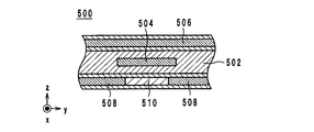
従来の信号線路に関する発明としては、例えば、特許文献1に記載のプリント配線板が知られている。図5は、特許文献1に記載のプリント配線板500の断面構造図である。図5において、上下方向をz軸方向と定義し、左右方向をy軸方向と定義し、紙面垂直方向をx軸方向と定義する。
As an invention related to a conventional signal line, for example, a printed wiring board described in Patent Document 1 is known. FIG. 5 is a cross-sectional structure diagram of a printed
プリント配線板500は、図5に示すように、絶縁層502、信号線504及び電極面506,508を備えている。信号線504は、絶縁層502内においてx軸方向に延在している。電極面506は、信号線504のz軸方向の正方向側に設けられている。電極面508は、信号線504のz軸方向の負方向側に設けられている。また、電極面508には、信号線504と重なるように、線状開口部510が設けられている。信号線504には、高周波信号が伝送される。電極面506,508には、接地電位が印加される。すなわち、信号線504及び電極面506,508は、ストリップライン構造を構成している。
As shown in FIG. 5, the printed
以上のように構成されたプリント配線板500では、プリント配線板500を湾曲させることが容易である。より詳細には、電極面508に線状開口部510が設けられている。そのため、電極面508は、線状開口部510が設けられていない電極面506に比べて弾性的に伸び縮みしやすくなる。よって、プリント配線板500を湾曲させることが容易である。
In the printed
しかしながら、プリント配線板500は、高周波信号に損失が発生するという問題を有する。より詳細には、高周波信号が信号線504内を伝送されると、電極面506,508を貫く磁界が信号線504の周囲に発生する。高周波信号は電流値が周期的に変動するので、磁界も周期的に変化する。このように磁界が周期的に変化すると、電極面506,508には、電磁誘導により磁界の変化を妨げる渦電流が発生する。その結果、信号線504内を伝送される高周波信号には、渦電流損が発生する。
However, the printed
そこで、本発明の目的は、容易に湾曲させることができると共に、高周波信号の損失を低減できる信号線路を提供することである。 Therefore, an object of the present invention is to provide a signal line that can be easily bent and can reduce loss of a high-frequency signal.
本発明の一形態に係る信号線路は、可撓性材料からなる複数の絶縁シートが積層されてなる本体と、前記本体に設けられている線状導体からなる信号線と、前記本体において前記信号線よりも積層方向の一方側に設けられ、かつ、積層方向から平面視したときに、該信号線と重なっているスリットが形成されている第1のグランド導体と、前記本体において前記信号線よりも積層方向の他方側に設けられ、かつ、積層方向から平面視したときに、該信号線と重なっている第2のグランド導体と、を備えており、前記第1のグランド導体、前記第2のグランド導体及び前記信号線は、ストリップライン構造を構成しており、前記第1のグランド導体と前記信号線との積層方向における間隔は、前記第2のグランド導体と該信号線との積層方向における間隔よりも小さいこと、を特徴とする。 A signal line according to an aspect of the present invention includes a main body in which a plurality of insulating sheets made of a flexible material are laminated, a signal line made of a linear conductor provided in the main body, and the signal in the main body. A first ground conductor provided on one side of the stacking direction from the line and formed with a slit overlapping the signal line when viewed in plan from the stacking direction; And a second ground conductor that is provided on the other side in the stacking direction and overlaps with the signal line when viewed in plan from the stacking direction, the first ground conductor, the second ground conductor The ground conductor and the signal line form a strip line structure, and the interval in the stacking direction of the first ground conductor and the signal line is the stacking direction of the second ground conductor and the signal line. In Less than kicking distance that features a.
本発明によれば、容易に湾曲させることができると共に、高周波信号の損失を低減できる。 According to the present invention, it is possible to easily bend and reduce the loss of a high-frequency signal.
以下に、本発明の実施形態に係る信号線路について図面を参照しながら説明する。 Hereinafter, a signal line according to an embodiment of the present invention will be described with reference to the drawings.
(信号線路の構成)
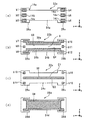
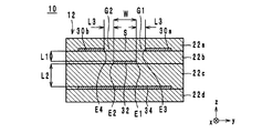
以下に、本発明の一実施形態に係る信号線路の構成について図面を参照しながら説明する。図1は、本発明の一実施形態に係る信号線路10の外観斜視図である。図2は、図1の信号線路10の分解図である。図3は、信号線路10の絶縁シート22b,22cを積層方向から透視した図である。図4は、図1のA−Aにおける断面構造図である。図1ないし図4において、信号線路10の積層方向をz軸方向と定義する。また、信号線路10の長手方向をx軸方向と定義し、x軸方向及びz軸方向に直交する方向をy軸方向と定義する。
(Configuration of signal line)
The configuration of a signal line according to an embodiment of the present invention will be described below with reference to the drawings. FIG. 1 is an external perspective view of a
信号線路10は、例えば、携帯電話等の電子機器内において、2つの回路基板を接続する。信号線路10は、図1及び図2に示すように、本体12、外部端子14(14a〜14f)、グランド導体30(30a,30b),34、信号線32及びビアホール導体b1〜b16を備えている。
For example, the
本体12は、図1に示すように、信号線部16及びコネクタ部18,20を含んでいる。信号線部16は、x軸方向に延在しており、信号線32及びグランド導体30,34を内蔵している。信号線部16は、U字状に曲げることができるように構成されている。コネクタ部18,20は、信号線部16のx軸方向の両端に設けられ、図示しない回路基板のコネクタに接続される。本体12は、図2に示す絶縁シート22(22a〜22d)がz軸方向の正方向側から負方向側へとこの順に積層されて構成されている。
As shown in FIG. 1, the
絶縁シート22は、可撓性を有する液晶ポリマー等の熱可塑性樹脂により構成されている。絶縁シート22a〜22dはそれぞれ、図2に示すように、信号線部24a〜24d及びコネクタ部26a〜26d,28a〜28dにより構成されている。信号線部24は、本体12の信号線部16を構成し、コネクタ部26,28はそれぞれ、本体12のコネクタ部18,20を構成している。なお、以下では、絶縁シート22のz軸方向の正方向側の主面を表面と称し、絶縁シート22のz軸方向の負方向側の主面を裏面と称す。
The
外部端子14a〜14cは、図2に示すように、コネクタ部26aの表面にy軸方向に一列に並ぶように設けられている。外部端子14a〜14cは、コネクタ部18が回路基板のコネクタに挿入された際に、コネクタ内の端子に接触する。具体的には、外部端子14a,14cは、コネクタ内のグランド端子に接触し、外部端子14bは、コネクタ内の信号端子に接触する。したがって、外部端子14a,14cには、グランド電位が印加され、外部端子14bには、高周波信号が印加される。
As shown in FIG. 2, the
外部端子14d〜14fは、図2に示すように、コネクタ部28aの表面にy軸方向に一列に並ぶように設けられている。外部端子14d〜14fは、コネクタ部20が回路基板のコネクタに挿入された際に、コネクタ内の端子に接触する。具体的には、外部端子14d,14fは、コネクタ内のグランド端子に接触し、外部端子14eは、コネクタ内の信号端子に接触する。したがって、外部端子14d,14fには、グランド電位が印加され、外部端子14eには、高周波信号が印加される。
As shown in FIG. 2, the
信号線32は、図2に示すように、絶縁シート22cの表面に設けられることにより、本体12内に設けられている線状導体である。具体的には、信号線32は、信号線部24cの表面をx軸方向に延在している。そして、信号線32の両端はそれぞれ、コネクタ部26c,28cに位置している。
As shown in FIG. 2, the
グランド導体30a,30bは、図2に示すように、本体12において信号線32よりもz軸方向の正方向側に設けられ、より詳細には、絶縁シート22bの表面に設けられている。グランド導体30a,30bは、信号線部24bの表面をx軸方向に互いに平行に延在している。グランド導体30a,30bの一端は、コネクタ部26bに位置し、グランド導体30a,30bの他端は、コネクタ部28bに位置している。グランド導体30a,30bには、z軸方向から平面視したときに、x軸方向に延在するスリットSが形成されている。以下に、スリットSについてより詳細に説明する。
As shown in FIG. 2, the
スリットSは、z軸方向から平面視したときに、信号線32と重なっている。具体的には、信号線32は、図2に示すように、x軸方向に延在している2本の縁部E1,E2を有している。また、グランド導体30a,30bはそれぞれ、x軸方向に延在している縁部E3,E4を有している。スリットSは、縁部E3,E4間に存在している。すなわち、スリットSは、縁部E3,E4に挟まれた領域である。そして、絶縁シート22c上に絶縁シート22bが重ねられたときに、図3に示すように、縁部E3は、縁部E1よりもy軸方向の正方向側に位置し、縁部E4は、縁部E2よりもy軸方向の負方向側に位置している。これにより、信号線32は、z軸方向から平面視したときに、スリットSからy軸方向にはみ出すことなく該スリットS内に収まった状態でx軸方向に延在している。すなわち、図3に示すように、縁部E1と縁部E3との間及び縁部E2と縁部E4との間にはそれぞれ、z軸方向から平面視したときに、グランド導体30a,30b及び信号線32が存在していない隙間G1,G2が存在している。ただし、信号線32のx軸方向の両端は、スリットSからはみ出している。
The slit S overlaps with the
グランド導体34は、図2に示すように、信号線32よりもz軸方向の負方向側に設けられ、より詳細には、絶縁シート22dの表面に設けられている。グランド導体34は、信号線部24dの表面をx軸方向に延在している。グランド導体34の一端は、コネクタ部26dにおいて2つに枝分かれした状態で位置し、グランド導体34の他端は、コネクタ部28dにおいて2つに枝分かれした状態で位置している。更に、グランド導体34は、図2に示すように、z軸方向から平面視したときに、信号線32と重なっている。
As shown in FIG. 2, the
以上のような構成を有するグランド導体30a,30b,34及び信号線32は、ストリップライン構造を構成している。すなわち、グランド導体30a,30bと信号線32との間には、容量が発生し、グランド導体34と信号線32との間には、容量が発生している。そして、これら2つの容量は、略等しい大きさを有している。
The
ビアホール導体b1,b3はそれぞれ、図2に示すように、コネクタ部26aをz軸方向に貫通するように設けられ、外部端子14a,14cとグランド導体30a,30bとを接続している。ビアホール導体b2は、図2に示すように、コネクタ部26aをz軸方向に貫通するように設けられ、外部端子14bに接続されている。
As shown in FIG. 2, the via-hole conductors b1 and b3 are provided so as to penetrate the
ビアホール導体b7,b9はそれぞれ、図2に示すように、コネクタ部26bをz軸方向に貫通するように設けられ、グランド導体30a,30bに接続されている。ビアホール導体b8は、図2に示すように、コネクタ部26bをz軸方向に貫通するように設けられ、ビアホール導体b2と信号線32とを接続している。
As shown in FIG. 2, the via-hole conductors b7 and b9 are provided so as to penetrate the
ビアホール導体b13,b14はそれぞれ、図2に示すように、コネクタ部26cをz軸方向に貫通するように設けられ、ビアホール導体b7,b9とグランド導体34とを接続している。これにより、外部端子14aとグランド導体30aとグランド導体34とがビアホール導体b1,b7,b13を介して接続され、外部端子14cとグランド導体30bとグランド導体34とがビアホール導体b3,b9,b14により接続されている。また、外部端子14bと信号線32とがビアホール導体b2,b8により接続されている。
As shown in FIG. 2, the via-hole conductors b13 and b14 are provided so as to penetrate the
ビアホール導体b4,b6はそれぞれ、図2に示すように、コネクタ部28aをz軸方向に貫通するように設けられ、外部端子14d,14fとグランド導体30a,30bとを接続している。ビアホール導体b5は、図2に示すように、コネクタ部28aをz軸方向に貫通するように設けられ、外部端子14eに接続されている。
As shown in FIG. 2, the via-hole conductors b4 and b6 are provided so as to penetrate the connector portion 28a in the z-axis direction, and connect the
ビアホール導体b10,b12はそれぞれ、図2に示すように、コネクタ部28bをz軸方向に貫通するように設けられ、グランド導体30a,30bに接続されている。ビアホール導体b11は、図2に示すように、コネクタ部28bをz軸方向に貫通するように設けられ、ビアホール導体b5と信号線32とを接続している。
As shown in FIG. 2, the via-hole conductors b10 and b12 are provided so as to penetrate the
ビアホール導体b15,b16はそれぞれ、図2に示すように、コネクタ部28cをz軸方向に貫通するように設けられ、ビアホール導体b10,b12とグランド導体34とを接続している。これにより、外部端子14dとグランド導体30aとグランド導体34とがビアホール導体b4,b10,b15を介して接続され、外部端子14fとグランド導体30bとグランド導体34とがビアホール導体b6,b12,b16により接続されている。また、外部端子14eと信号線32とがビアホール導体b5,b11により接続されている。
As shown in FIG. 2, the via-hole conductors b15 and b16 are provided so as to penetrate the connector portion 28c in the z-axis direction, and connect the via-hole conductors b10 and b12 and the
次に、図4を参照しながら、信号線部16の断面構造について説明する。グランド導体30a,30bと信号線32とのz軸方向における間隔L1(以下、グランド導体30a,30bと信号線32との間隔L1と呼ぶ)は、グランド導体34と信号線32とのz軸方向における間隔L2(以下、グランド導体34と信号線32との間隔L2と呼ぶ)よりも小さい。より詳細には、絶縁シート22a,22b,22dは、z軸方向において同じ厚みを有している。一方、絶縁シート22cは、絶縁シート22a,22b,22dよりも、z軸方向において大きな厚みを有している。そして、グランド導体30a,30bと信号線32との間には、絶縁シート22bが設けられている。また、グランド導体34と信号線32との間には、絶縁シート22cが設けられている。その結果、グランド導体30a,30bと信号線32との間隔L1は、グランド導体34と信号線32との間隔L2よりも小さくなる。
Next, a cross-sectional structure of the signal line portion 16 will be described with reference to FIG. The distance L1 between the
以下に、信号線路10の各部分のサイズの一例を挙げておく。z軸方向から平面視したときに、縁部E1と縁部E3との間隔L3及び縁部E2と縁部E4との間隔L3は、32.5μm以上97.5μm以下である。間隔L3は、特に、65μm程度であることが望ましい。また、グランド導体30a,30bと信号線32との間隔L1は、25μm以上75μm以下である。間隔L1は、例えば、50μm程度であることが望ましい。グランド導体34と信号線32との間隔L2は、50μm以上150μm以下である。間隔L2は、例えば、100μm程度であることが望ましい。また、信号線32のy軸方向における幅Wは、140μmである。また、信号線32、グランド導体30a,30b,34のz軸方向における厚みは、18μmである。
Below, an example of the size of each part of the signal track |
(信号線路の製造方法)
以下に、信号線路10の製造方法について図面を参照しながら説明する。以下では、一つの信号線路10が作製される場合を例にとって説明するが、実際には、大判の絶縁シートが積層及びカットされることにより、同時に複数の信号線路10が作製される。
(Signal line manufacturing method)
Below, the manufacturing method of the signal track |
まず、表面の全面に銅箔が形成された液晶ポリマー等の熱可塑性樹脂からなる絶縁シート22を準備する。次に、図2に示す外部端子14を絶縁シート22aの表面に形成する。具体的には、フォトリソグラフィ工程により、絶縁シート22aの銅箔上に、図2に示す外部端子14と同じ形状のレジストを形成する。そして、銅箔に対してエッチング処理を施すことにより、レジストにより覆われていない部分の銅箔を除去する。その後、レジストを除去する。これにより、図2に示すような、外部端子14が絶縁シート22aの表面に形成される。
First, an insulating
次に、図2に示すグランド導体30a,30bを絶縁シート22bの表面に形成する。また、フォトリソグラフィ工程により、図2に示す信号線32を絶縁シート22cの表面に形成する。また、フォトリソグラフィ工程により、図2に示すグランド導体34を絶縁シート22dの表面に形成する。なお、これらのフォトリソグラフィ工程は、外部端子14を形成する際のフォトリソグラフィ工程と同様であるので、説明を省略する。
Next, the
次に、絶縁シート22a〜22cのビアホール導体b1〜b16が形成される位置に対して、裏面側からレーザービームを照射して、ビアホールを形成する。その後、絶縁シート22a〜22cに形成したビアホールに対して、銅を主成分とする導電性ペーストを充填し、図2に示すビアホール導体b1〜b16を形成する。
Next, a laser beam is irradiated from the back side to the positions where the via hole conductors b1 to b16 of the insulating
次に、絶縁シート22a〜22dをこの順に積み重ねる。そして、絶縁シート22a〜22dに対してz軸方向の正方向側及び負方向側から等方的に又は弾性体を介して力を加えることにより、絶縁シート22a〜22dを圧着する。これにより、図1に示す信号線路10が得られる。
Next, the insulating
(効果)
以上のような信号線路10によれば、本体12をz軸方向の正方向側に突出するようにU字状に湾曲させることが容易となる。より詳細には、特許文献1のように構成されたプリント配線板500では、プリント配線板500を湾曲させることが容易である。より詳細には、電極面508に線状開口部510が設けられている。そのため、電極面508は、線状開口部510が設けられていない電極面506に比べて弾性的に伸び縮みしやすくなる。よって、プリント配線板500を湾曲させることが容易である。
(effect)
According to the
また、信号線路10では、グランド導体30a,30bにスリットSが設けられているので、グランド導体30a,30bの面積は、グランド導体34の面積よりも小さくなる。よって、グランド導体30a,30bは、グランド導体34よりも伸びやすい。その結果、グランド導体30a,30bがグランド導体34よりも外周側に位置するように、本体12をz軸方向の正方向側である第1のグランド導体側に突出するように湾曲させることが容易となる。
Further, in the
また、信号線路10によれば、以下の理由によっても、本体12をz軸方向の正方向側である第1のグランド導体側に突出するようにU字状に湾曲させることが容易となる。より詳細には、信号線路10では、信号線32が所定の特性インピーダンス(例えば、50Ω)を有している必要がある。ここで、信号線路10においてスリットSを設けた場合には、信号線路10にスリットSが設けられていない場合に比べて、グランド導体30a,30bと信号線32とが対向する面積が小さくなってしまい、グランド導体30a,30bと信号線32との間に発生する容量も小さくなってしまう。そこで、信号線路10では、図4に示すように、絶縁シート22bのz軸方向における厚みを小さくして、グランド導体30a,30bと信号線32との間隔L1を小さくしている。これにより、グランド導体30a,30bと信号線32との間に発生する容量を大きくして、信号線32において所定の特性インピーダンスを得ている。更に、絶縁シート22bのz軸方向における厚みを小さくすることにより、本体12のz軸方向における厚みが小さくなるので、本体12の剛性が低くなる。その結果、信号線路10では、本体12を湾曲させることが容易となる。
Further, according to the
また、信号線路10では、高周波信号の損失の発生を低減できる。より詳細には、特許文献1に記載のプリント配線板500では、高周波信号が信号線504内を伝送されると、電極面506,508を貫く磁界が信号線504の周囲に発生する。高周波信号は電流値が周期的に変動するので、磁界も周期的に変化する。このように磁界が周期的に変化すると、電極面506,508には、電磁誘導により磁界の変化を妨げる渦電流が発生する。その結果、信号線504内を伝送される高周波信号には、渦電流損が発生する。特に、プリント配線板500では、図5に示すように、電極面506と信号線504との間隔、及び、電極面508と信号線504との間隔が等しく、更に、電極面508には、線状開口部510が設けられている。よって、渦電流は、主に電極面506で発生し、電極面508では殆ど発生しない。以上より、プリント配線板500では、スリットSが設けられていない電極面506において発生する渦電流を抑制することが重要である。
Further, the
そこで、信号線路10では、図4に示すように、グランド導体30a,30bと信号線32との間隔L1を、グランド導体34と信号線32との間隔L2よりも小さくしている。すなわち、信号線32を、グランド導体34から離し、かつ、グランド導体30a,30bに近づけている。これにより、信号線32を伝送される高周波信号によりグランド導体34に発生する渦電流を低減できる。一方、グランド導体30a,30bにはスリットSが設けられているので、信号線32を伝送される高周波信号によりグランド導体30a,30bに発生する渦電流は殆ど増加しない。よって、信号線路10全体で見た場合には、渦電流は減少する。その結果、信号線路10では、高周波信号の損失を低減できる。
Therefore, in the
また、信号線路10では、以下に説明するように、製造ばらつきによる特性インピーダンスのばらつきを低減できる。より詳細には、絶縁シート22a〜22dを積層する際に、積層ずれが発生する可能性がある。この場合、図4において、縁部E1と縁部E3とが重なり、かつ、縁部E2と縁部E4とが重なるように信号線路10が設計されていると、僅かな積層ずれによって、グランド導体30a又はグランド導体30bと信号線32とがz軸方向から平面視したときに重なってしまう。その結果、グランド導体30a又はグランド導体30bと信号線32との間に大きな容量が発生してしまい、信号線路10の特性インピーダンスが大きく変化してしまう。
Further, in the
そこで、信号線路10では、図3に示すように、縁部E1と縁部E3との間及び縁部E2と縁部E4との間にはそれぞれ、z軸方向から平面視したときに、グランド導体30a,30b及び信号線32が存在していない隙間G1,G2を設けている。これにより、絶縁シート22a〜22dに積層ずれが発生したとしても、グランド導体30a,30bと信号線32とがz軸方向から平面視したときに重なることが防止される。その結果、グランド導体30a又はグランド導体30bと信号線32との間に大きな容量が発生することが防止され、信号線路10の特性インピーダンスが大きく変化することが防止される。
Therefore, in the
また、信号線路10では、間隔L2は、50μm以上75μm以下であり、間隔L3は、32.5μm以上97.5μm以下である。そして、好ましくは、間隔L2は、100μm程度であり、間隔L3は、65μm程度である。これにより、スリットSのy軸方向における幅とグランド導体30a,30bと信号線32との間隔L1とを適正な関係にすることができる。その結果、信号線32内を伝送される高周波信号による不要輻射がスリットSから放射されることが防止される。
In the
また、信号線路10では、以下に説明するように、本体12を湾曲させやすくしつつ、直流抵抗値を低減することができる。より詳細には、信号線路10において、本体12を湾曲させやすくするためには、例えば、本体12のz軸方向における厚みを小さくすることが挙げられる。ただし、スリットSを設けることなく本体12のz軸方向における厚みを小さくした場合には、信号線32とグランド導体30a,30b,34との間に発生する容量は大きくなる。したがって、この場合には、信号線32のy軸方向における幅Wを小さくして、容量を小さくする必要がある。しかしながら、信号線32のy軸方向における幅Wを小さくすると、信号線32の直流抵抗値が大きくなってしまう。
Further, in the
そこで、信号線路10では、グランド導体30a,30bにスリットSを設けている。これにより、グランド導体30a,30bと信号線32との間に容量が発生しにくくなるので、信号線32のy軸方向における幅Wを変化させることなくグランド導体30a,30bと信号線32とを近づけることができる。すなわち、信号線32の直流抵抗を大きくすることなく、本体12のz軸方向における厚みを小さくすることができる。その結果、信号線路10では、本体12を湾曲させやすくしつつ、直流抵抗値を低減することができる。
Therefore, in the
本願発明者は、信号線路10が奏する効果をより明確なものとするために、以下に説明する実験を行った。信号線路10のモデルとして、幅Wが140μmであり、グランド導体30a,30bとグランド導体34とのz軸方向における間隔が150μmである第1のモデルを作成した。また、比較例に係るモデルとして、信号線路10においてスリットSが設けられておらず、かつ、幅Wが70μmであり、グランド導体30a,30bとグランド導体34とのz軸方向における間隔が150μmである第2のモデルを作成した。なお、第1のモデルと第2のモデルとでは、特性インピーダンスは等しくなるように設計されている。
The inventor of the present application conducted an experiment described below in order to make the effect of the
以上のような第1のモデル及び第2のモデルに対して、2GHzの周波数を有する高周波信号を伝送させ、高周波信号に発生した損失を計算した。その結果、第1のモデルでは、高周波信号に発生した損失は、0.15dBであったのに対し、第2のモデルでは、高周波信号に発生した損失は、0.22dBであった。これは、第1のモデルよりも第2のモデルの方が、信号線32における幅Wが小さく、信号線32の直流抵抗値が大きいためである。よって、信号線路10では、所望の特性インピーダンスを維持しつつ、直流抵抗値を低減することが可能であることが分かる。
For the first model and the second model as described above, a high frequency signal having a frequency of 2 GHz was transmitted, and the loss generated in the high frequency signal was calculated. As a result, in the first model, the loss generated in the high-frequency signal was 0.15 dB, whereas in the second model, the loss generated in the high-frequency signal was 0.22 dB. This is because the width W of the
本発明は、信号線路に有用であり、特に、容易に湾曲させることができると共に、高周波信号に発生する損失を低減できる点において優れている。 The present invention is useful for a signal line, and is particularly excellent in that it can be easily bent and loss generated in a high-frequency signal can be reduced.
b1〜b16 ビアホール導体
10 信号線路
12 本体
14a〜14f 外部端子
16 信号線部
18,20 コネクタ部
22a〜22d 絶縁シート
30a,30b,34 グランド導体
32 信号線
b1 to b16
本発明の一形態に係る信号線路は、可撓性材料からなる複数の絶縁シートが積層されてなる本体と、前記本体に設けられている線状導体からなる信号線と、前記本体において前記信号線よりも積層方向の一方側に設けられている第1のグランド導体と、前記本体において前記信号線よりも積層方向の他方側に設けられている第2のグランド導体と、を備えており、前記信号線の延在方向と直交する方向において、前記第1のグランド導体と該信号線との積層方向における間隔が前記第2のグランド導体と該信号線との積層方向における間隔よりも小さく、かつ、積層方向から平面視したときに、該第1のグランド導体に該信号線と重ならない領域が設けられた断面構造が存在すること、を特徴とする。 A signal line according to an aspect of the present invention includes a main body in which a plurality of insulating sheets made of a flexible material are laminated, a signal line made of a linear conductor provided in the main body, and the signal in the main body. It comprises a first ground conductor are found provided on one side in the stacking direction than the line, and a second ground conductor are found on the other side in the stacking direction than the signal line in the body In the direction orthogonal to the extending direction of the signal line, the interval in the stacking direction of the first ground conductor and the signal line is larger than the interval in the stacking direction of the second ground conductor and the signal line. It is small and has a cross-sectional structure in which the first ground conductor has a region that does not overlap with the signal line when viewed in plan from the stacking direction .
Claims (5)
前記本体に設けられている線状導体からなる信号線と、
前記本体において前記信号線よりも積層方向の一方側に設けられ、かつ、積層方向から平面視したときに、該信号線と重なっているスリットが形成されている第1のグランド導体と、
前記本体において前記信号線よりも積層方向の他方側に設けられ、かつ、積層方向から平面視したときに、該信号線と重なっている第2のグランド導体と、
を備えており、
前記第1のグランド導体、前記第2のグランド導体及び前記信号線は、ストリップライン構造を構成しており、
前記第1のグランド導体と前記信号線との積層方向における間隔は、前記第2のグランド導体と該信号線との積層方向における間隔よりも小さいこと、
を特徴とする信号線路。 A main body in which a plurality of insulating sheets made of a flexible material are laminated;
A signal line made of a linear conductor provided in the main body;
A first ground conductor provided on one side of the main body in the stacking direction with respect to the signal line, and formed with a slit overlapping the signal line when viewed in plan from the stacking direction;
A second ground conductor provided on the other side of the main body in the stacking direction from the signal line and overlapping the signal line when viewed in plan from the stacking direction;
With
The first ground conductor, the second ground conductor and the signal line constitute a stripline structure,
An interval in the stacking direction between the first ground conductor and the signal line is smaller than an interval in the stacking direction between the second ground conductor and the signal line;
A signal line characterized by
前記スリットは、前記2本の第1の縁部の間に存在しており、
前記信号線は、所定方向に延在する2本の第2の縁部を有しており、
前記第1の縁部と前記第2の縁部との間にはそれぞれ、積層方向から平面視したときに、前記第1のグランド導体又は前記信号線が存在していないこと、
を特徴とする請求項1に記載の信号線路。 The first ground conductor has two first edges extending in a predetermined direction,
The slit exists between the two first edges;
The signal line has two second edges extending in a predetermined direction,
The first ground conductor or the signal line does not exist between the first edge and the second edge when viewed in plan from the stacking direction,
The signal line according to claim 1.
前記第1のグランド導体と前記信号線との積層方向における間隔は、25μm以上75μm以下であり、
前記第2のグランド導体と前記信号線との積層方向における間隔は、50μm以上150μm以下であること、
を特徴とする請求項2に記載の信号線路。 When viewed in plan from the stacking direction, the distance between the first edge and the second edge is 32.5 μm or more and 97.5 μm or less,
An interval in the stacking direction between the first ground conductor and the signal line is 25 μm or more and 75 μm or less,
An interval in the stacking direction between the second ground conductor and the signal line is not less than 50 μm and not more than 150 μm;
The signal line according to claim 2.
更に備えていること、
を特徴とする請求項1ないし請求項3のいずれかに記載の信号線路。 A via-hole conductor connecting the first ground conductor and the second ground conductor;
More
The signal line according to claim 1, wherein:
を特徴とする請求項1ないし請求項4のいずれかに記載の信号線路。 The body is curved so as to protrude toward the first ground conductor in the stacking direction so that the first ground conductor is located on the outer peripheral side of the second ground conductor;
The signal line according to claim 1, wherein:
Priority Applications (1)
| Application Number | Priority Date | Filing Date | Title |
|---|---|---|---|
| JP2012106486A JP5505455B2 (en) | 2009-08-11 | 2012-05-08 | Signal line |
Applications Claiming Priority (3)
| Application Number | Priority Date | Filing Date | Title |
|---|---|---|---|
| JP2009186283 | 2009-08-11 | ||
| JP2009186283 | 2009-08-11 | ||
| JP2012106486A JP5505455B2 (en) | 2009-08-11 | 2012-05-08 | Signal line |
Related Parent Applications (1)
| Application Number | Title | Priority Date | Filing Date |
|---|---|---|---|
| JP2011526709A Division JP4993037B2 (en) | 2009-08-11 | 2010-07-21 | Signal line |
Publications (2)
| Publication Number | Publication Date |
|---|---|
| JP2012182826A true JP2012182826A (en) | 2012-09-20 |
| JP5505455B2 JP5505455B2 (en) | 2014-05-28 |
Family
ID=43586113
Family Applications (2)
| Application Number | Title | Priority Date | Filing Date |
|---|---|---|---|
| JP2011526709A Active JP4993037B2 (en) | 2009-08-11 | 2010-07-21 | Signal line |
| JP2012106486A Active JP5505455B2 (en) | 2009-08-11 | 2012-05-08 | Signal line |
Family Applications Before (1)
| Application Number | Title | Priority Date | Filing Date |
|---|---|---|---|
| JP2011526709A Active JP4993037B2 (en) | 2009-08-11 | 2010-07-21 | Signal line |
Country Status (4)
| Country | Link |
|---|---|
| US (1) | US8810340B2 (en) |
| JP (2) | JP4993037B2 (en) |
| CN (1) | CN102474980B (en) |
| WO (1) | WO2011018934A1 (en) |
Cited By (4)
| Publication number | Priority date | Publication date | Assignee | Title |
|---|---|---|---|---|
| WO2014077119A1 (en) * | 2012-11-14 | 2014-05-22 | 株式会社村田製作所 | Wiring substrate and electronic device using same |
| WO2014157031A1 (en) * | 2013-03-26 | 2014-10-02 | 株式会社村田製作所 | High-frequency transmission line and electronic device |
| WO2015005028A1 (en) * | 2013-07-09 | 2015-01-15 | 株式会社村田製作所 | High-frequency transmission line |
| CN112867226A (en) * | 2019-11-27 | 2021-05-28 | 鹏鼎控股(深圳)股份有限公司 | High-frequency transmission circuit board and manufacturing method thereof |
Families Citing this family (18)
| Publication number | Priority date | Publication date | Assignee | Title |
|---|---|---|---|---|
| US9462676B2 (en) * | 2009-11-06 | 2016-10-04 | Molex, Llc | Multi-layer circuit member with reference circuit |
| WO2013080887A1 (en) | 2011-12-02 | 2013-06-06 | 株式会社村田製作所 | High-frequency signal wire paths, method for manufacturing the same, and electronic device |
| JP5472553B2 (en) * | 2011-12-29 | 2014-04-16 | 株式会社村田製作所 | High frequency signal lines and electronic equipment |
| JP5472552B2 (en) * | 2011-12-29 | 2014-04-16 | 株式会社村田製作所 | High frequency signal lines and electronic equipment |
| JP5794218B2 (en) | 2012-02-14 | 2015-10-14 | 株式会社村田製作所 | High frequency signal line and electronic device equipped with the same |
| WO2014002766A1 (en) | 2012-06-29 | 2014-01-03 | 株式会社村田製作所 | High-frequency signal line |
| WO2014003088A1 (en) * | 2012-06-29 | 2014-01-03 | 株式会社村田製作所 | Flat cable |
| JP5888274B2 (en) * | 2012-06-29 | 2016-03-16 | 株式会社村田製作所 | High frequency lines and electronic equipment |
| JP5527493B1 (en) * | 2012-06-29 | 2014-06-18 | 株式会社村田製作所 | Flat cable and electronics |
| CN204271225U (en) | 2012-06-29 | 2015-04-15 | 株式会社村田制作所 | High-frequency signal circuit |
| JP5935620B2 (en) * | 2012-09-18 | 2016-06-15 | 株式会社村田製作所 | Flat cable |
| US9166550B2 (en) * | 2013-03-14 | 2015-10-20 | Avago Technologies General Ip (Singapore) Pte. Ltd. | System and method for using a reference plane to control transmission line characteristic impedance |
| CN104733823A (en) * | 2015-04-14 | 2015-06-24 | 上海安费诺永亿通讯电子有限公司 | Bendable flat transmission line |
| US20160329130A1 (en) * | 2015-05-07 | 2016-11-10 | Wilson Electronics, Llc | Flat coaxial cable |
| JP6493557B2 (en) * | 2015-11-27 | 2019-04-03 | 富士通株式会社 | Circuit board and electronic device |
| KR20210093929A (en) * | 2018-11-28 | 2021-07-28 | 호시덴 가부시기가이샤 | High-frequency transmission device and high-frequency signal transmission method |
| WO2020129827A1 (en) * | 2018-12-17 | 2020-06-25 | 株式会社村田製作所 | Multilayered substrate |
| KR20210012821A (en) | 2019-07-26 | 2021-02-03 | 삼성전자주식회사 | Electronic device including flexible printed circuit board |
Citations (4)
| Publication number | Priority date | Publication date | Assignee | Title |
|---|---|---|---|---|
| JP2006222370A (en) * | 2005-02-14 | 2006-08-24 | Mikku:Kk | Circuit board combining different material |
| JP2007123740A (en) * | 2005-10-31 | 2007-05-17 | Sony Corp | Flexible board, optical transmission/reception module and optical transmission/reception device |
| JP2009032765A (en) * | 2007-07-25 | 2009-02-12 | Canon Inc | Print circuit board and electronic device using the same |
| JP2009054876A (en) * | 2007-08-28 | 2009-03-12 | Sumitomo Bakelite Co Ltd | Printed wiring board |
Family Cites Families (12)
| Publication number | Priority date | Publication date | Assignee | Title |
|---|---|---|---|---|
| US3961296A (en) * | 1975-03-06 | 1976-06-01 | Motorola, Inc. | Slotted strip-line |
| SE468573B (en) * | 1991-06-14 | 1993-02-08 | Ericsson Telefon Ab L M | DEVICES WITH FLEXIBLE, ORIENTATED STRIPLINE PIPES AND PROCEDURES FOR PREPARING SUCH A DEVICE |
| JP3350792B2 (en) * | 1993-04-28 | 2002-11-25 | 株式会社村田製作所 | Parallel stripline cable |
| FI106414B (en) * | 1999-02-02 | 2001-01-31 | Nokia Networks Oy | Broadband impedance adapter |
| JP2000323847A (en) * | 1999-05-11 | 2000-11-24 | Shinko Electric Ind Co Ltd | Multilayer wiring circuit board |
| JP2004228344A (en) * | 2003-01-23 | 2004-08-12 | Oki Electric Cable Co Ltd | Multilayered fpc |
| US20050083147A1 (en) * | 2003-10-20 | 2005-04-21 | Barr Andrew H. | Circuit board and method in which the impedance of a transmission-path is selected by varying at least one opening in a proximate conductive plane |
| US7224249B2 (en) * | 2005-09-08 | 2007-05-29 | Avago Technologies General Ip (Singapore) Pte. Ltd. | Stripline structure with multiple ground vias separated by no more than 100 mil |
| JP2007174075A (en) * | 2005-12-20 | 2007-07-05 | Shinko Electric Ind Co Ltd | Differential transmission path structure and wiring board |
| DE102006047427B4 (en) * | 2006-10-06 | 2012-10-25 | Epcos Ag | Substrate with HF-capable cable |
| JP4852442B2 (en) | 2007-02-15 | 2012-01-11 | 日本オプネクスト株式会社 | Optical transmission module |
| JP2009032874A (en) * | 2007-07-26 | 2009-02-12 | Toshiba Corp | Printed circuit board |
-
2010
- 2010-07-21 JP JP2011526709A patent/JP4993037B2/en active Active
- 2010-07-21 WO PCT/JP2010/062240 patent/WO2011018934A1/en active Application Filing
- 2010-07-21 CN CN201080036168.8A patent/CN102474980B/en active Active
-
2012
- 2012-02-07 US US13/367,392 patent/US8810340B2/en active Active
- 2012-05-08 JP JP2012106486A patent/JP5505455B2/en active Active
Patent Citations (4)
| Publication number | Priority date | Publication date | Assignee | Title |
|---|---|---|---|---|
| JP2006222370A (en) * | 2005-02-14 | 2006-08-24 | Mikku:Kk | Circuit board combining different material |
| JP2007123740A (en) * | 2005-10-31 | 2007-05-17 | Sony Corp | Flexible board, optical transmission/reception module and optical transmission/reception device |
| JP2009032765A (en) * | 2007-07-25 | 2009-02-12 | Canon Inc | Print circuit board and electronic device using the same |
| JP2009054876A (en) * | 2007-08-28 | 2009-03-12 | Sumitomo Bakelite Co Ltd | Printed wiring board |
Cited By (5)
| Publication number | Priority date | Publication date | Assignee | Title |
|---|---|---|---|---|
| WO2014077119A1 (en) * | 2012-11-14 | 2014-05-22 | 株式会社村田製作所 | Wiring substrate and electronic device using same |
| WO2014157031A1 (en) * | 2013-03-26 | 2014-10-02 | 株式会社村田製作所 | High-frequency transmission line and electronic device |
| WO2015005028A1 (en) * | 2013-07-09 | 2015-01-15 | 株式会社村田製作所 | High-frequency transmission line |
| US9570786B2 (en) | 2013-07-09 | 2017-02-14 | Murata Manufacturing Co., Ltd. | High-frequency transmission line |
| CN112867226A (en) * | 2019-11-27 | 2021-05-28 | 鹏鼎控股(深圳)股份有限公司 | High-frequency transmission circuit board and manufacturing method thereof |
Also Published As
| Publication number | Publication date |
|---|---|
| WO2011018934A1 (en) | 2011-02-17 |
| CN102474980A (en) | 2012-05-23 |
| JPWO2011018934A1 (en) | 2013-01-17 |
| US8810340B2 (en) | 2014-08-19 |
| US20120133458A1 (en) | 2012-05-31 |
| JP5505455B2 (en) | 2014-05-28 |
| JP4993037B2 (en) | 2012-08-08 |
| CN102474980B (en) | 2015-04-01 |
Similar Documents
| Publication | Publication Date | Title |
|---|---|---|
| JP5505455B2 (en) | Signal line | |
| JP5310949B2 (en) | High frequency signal line | |
| JP5477422B2 (en) | High frequency signal line | |
| JP5463823B2 (en) | Signal line | |
| JP5741781B1 (en) | High frequency signal transmission line and electronic equipment | |
| WO2013190859A1 (en) | Layered multi-core cable | |
| WO2010150588A1 (en) | Signal transmission line | |
| JPWO2013080887A1 (en) | High frequency signal line, method for manufacturing the same, and electronic device | |
| JP5472555B2 (en) | High frequency signal transmission line and electronic equipment | |
| JP5472556B2 (en) | High frequency signal lines and electronic equipment | |
| WO2011007659A1 (en) | Signal line path and method for manufacturing same | |
| JP5637340B2 (en) | Flat cable | |
| JP5765468B2 (en) | High frequency signal line | |
| JP5704286B2 (en) | High frequency signal line | |
| JP5375319B2 (en) | Signal line and manufacturing method thereof | |
| JP5472552B2 (en) | High frequency signal lines and electronic equipment | |
| WO2014115678A1 (en) | High frequency signal transmission line, and electronic apparatus | |
| JP5660182B2 (en) | Signal line manufacturing method | |
| WO2014065172A1 (en) | Flexible substrate | |
| JP2014060042A (en) | Flat cable | |
| JP2014078836A (en) | High-frequency signal line and method of manufacturing the same | |
| JP2013135173A (en) | High frequency signal line |
Legal Events
| Date | Code | Title | Description |
|---|---|---|---|
| A977 | Report on retrieval |
Free format text: JAPANESE INTERMEDIATE CODE: A971007 Effective date: 20130724 |
|
| A131 | Notification of reasons for refusal |
Free format text: JAPANESE INTERMEDIATE CODE: A131 Effective date: 20130806 |
|
| A521 | Written amendment |
Free format text: JAPANESE INTERMEDIATE CODE: A523 Effective date: 20130920 |
|
| TRDD | Decision of grant or rejection written | ||
| A01 | Written decision to grant a patent or to grant a registration (utility model) |
Free format text: JAPANESE INTERMEDIATE CODE: A01 Effective date: 20140218 |
|
| A61 | First payment of annual fees (during grant procedure) |
Free format text: JAPANESE INTERMEDIATE CODE: A61 Effective date: 20140303 |
|
| R150 | Certificate of patent or registration of utility model |
Ref document number: 5505455 Country of ref document: JP Free format text: JAPANESE INTERMEDIATE CODE: R150 |