JP2012180687A - Safety box - Google Patents
Safety box Download PDFInfo
- Publication number
- JP2012180687A JP2012180687A JP2011044602A JP2011044602A JP2012180687A JP 2012180687 A JP2012180687 A JP 2012180687A JP 2011044602 A JP2011044602 A JP 2011044602A JP 2011044602 A JP2011044602 A JP 2011044602A JP 2012180687 A JP2012180687 A JP 2012180687A
- Authority
- JP
- Japan
- Prior art keywords
- weight
- housing
- main body
- storage
- casing
- Prior art date
- Legal status (The legal status is an assumption and is not a legal conclusion. Google has not performed a legal analysis and makes no representation as to the accuracy of the status listed.)
- Granted
Links
Images
Classifications
-
- E—FIXED CONSTRUCTIONS
- E05—LOCKS; KEYS; WINDOW OR DOOR FITTINGS; SAFES
- E05G—SAFES OR STRONG-ROOMS FOR VALUABLES; BANK PROTECTION DEVICES; SAFETY TRANSACTION PARTITIONS
- E05G1/00—Safes or strong-rooms for valuables
- E05G1/005—Portable strong boxes, e.g. which may be fixed to a wall or the like
-
- Y—GENERAL TAGGING OF NEW TECHNOLOGICAL DEVELOPMENTS; GENERAL TAGGING OF CROSS-SECTIONAL TECHNOLOGIES SPANNING OVER SEVERAL SECTIONS OF THE IPC; TECHNICAL SUBJECTS COVERED BY FORMER USPC CROSS-REFERENCE ART COLLECTIONS [XRACs] AND DIGESTS
- Y10—TECHNICAL SUBJECTS COVERED BY FORMER USPC
- Y10T—TECHNICAL SUBJECTS COVERED BY FORMER US CLASSIFICATION
- Y10T70/00—Locks
- Y10T70/50—Special application
- Y10T70/5009—For portable articles
- Y10T70/5031—Receptacle
-
- Y—GENERAL TAGGING OF NEW TECHNOLOGICAL DEVELOPMENTS; GENERAL TAGGING OF CROSS-SECTIONAL TECHNOLOGIES SPANNING OVER SEVERAL SECTIONS OF THE IPC; TECHNICAL SUBJECTS COVERED BY FORMER USPC CROSS-REFERENCE ART COLLECTIONS [XRACs] AND DIGESTS
- Y10—TECHNICAL SUBJECTS COVERED BY FORMER USPC
- Y10T—TECHNICAL SUBJECTS COVERED BY FORMER US CLASSIFICATION
- Y10T70/00—Locks
- Y10T70/70—Operating mechanism
- Y10T70/7051—Using a powered device [e.g., motor]
- Y10T70/7062—Electrical type [e.g., solenoid]
- Y10T70/7068—Actuated after correct combination recognized [e.g., numerical, alphabetical, or magnet[s] pattern]
Abstract
Description
本発明は、海や山のアウトドアでのレジャー等の際に貴重品を収納するために用いるセーフティボックスに関し、特に、非使用時には容易に持ち運び可能なセーフティボックスに関する。 The present invention relates to a safety box used for storing valuables during leisure activities in the sea or mountains outdoors, and more particularly to a safety box that can be easily carried when not in use.
従来、アウトドアでのレジャーの際に、財布、携帯電話、免許証等の貴重品の保管に困ることがよくある。例えば、海水浴や登山等では、貴重品を身につけることが困難な場合、拠点となる場所に貴重品を置いたまま、泳いだり登攀したりすることがある。このようなときに参加者が交替で貴重品を見張らなければならないと、全員で楽しむことができなくなる。特許文献1では、防水の貴重品携帯用ポーチを提示しているが、どのようにコンパクトなものであっても身につけるものである以上、動きの妨げとなる等の支障は避けられない。 Conventionally, during outdoor leisure, it is often difficult to store valuables such as wallets, mobile phones, and licenses. For example, when it is difficult to wear valuables, such as swimming or climbing, there are cases where swimming or climbing is carried out with the valuables left at the base location. In such a case, if the participants have to watch out for valuables in turn, everyone will not be able to enjoy it. In Patent Document 1, a waterproof valuables portable pouch is presented, but no matter how compact it is worn, problems such as hindering movement are unavoidable.
そこで、特許文献2では、蓋付きの開口部を有し貴重品と重量物とを収納する携帯用収納体を提示している。使用時には海水、砂、石等を重量物として収納し、収納体を持ち運び難くすることにより盗難防止を図るものである。 Therefore, Patent Document 2 presents a portable storage body that has an opening with a lid and stores valuables and heavy objects. In use, seawater, sand, stones and the like are stored as heavy objects, and the storage body is made difficult to carry, thereby preventing theft.
しかしながら、特許文献2の携帯用収納体は、蓋と収納体を一般的な手動式の錠で連結しロックするものであるので、少なくとも鍵は身につけておく必要がある。また、鍵を紛失すると解錠できなくなるという問題がある。また、収納体の重量にも拘わらずこれを持ち去ろうとする行為に対する対抗策は考慮されていない。 However, since the portable storage body of Patent Document 2 connects and locks the lid and the storage body with a general manual-type lock, it is necessary to wear at least the key. Another problem is that if the key is lost, it cannot be unlocked. In addition, countermeasures against the act of taking away the container regardless of the weight of the container are not considered.
本発明は、上記の従来技術の問題点に鑑み、非使用時には容易に持ち運びでき、使用時には相当の重量を付与できるセーフティボックスであって、施錠及び解錠の操作が容易であり、鍵を紛失するおそれが無く、強制的な持ち去り行為に対する対抗手段を備えたものを提供することを目的とする。 In view of the above-mentioned problems of the prior art, the present invention is a safety box that can be easily carried when not in use and can give a considerable weight when used, and is easy to lock and unlock, and loses its key. The purpose is to provide a device with a countermeasure against forced removal.
上記の目的を達成するべく、本発明は以下の構成を提供する。括弧内の数字は、後述する図面中の符号であり、参考のために付する。
本発明によるセーフティボックスは、錘部(11)と収納部(12)とを設けられた本体筐体(10)を有し、前記重錘部(11)は、前記本体筐体(10)の一部を形成する重錘部筐体(11a)と、前記重錘部筐体(11a)で囲まれ重錘物を収納するための重錘部空間(11b)と、前記重錘部空間(11b)内に重錘物を充填又は排出するための開口(11c,11d)と、を備え、前記収納部(12)は、前記本体筐体(10)の一部を形成する収納部筐体(12a)と、前記収納部筐体(12a)で囲まれ対象物品を収納するための収納部空間(12b)と、前記収納部空間(12b)を閉鎖するための開閉可能な収納部蓋(12c)と、前記収納部蓋(12c)を閉状態に保持するための電気錠(14)と、所定の情報を入力されることにより前記電気錠(14)の施錠及び解錠を制御する制御装置(17)と、を備えたことを特徴とする。
In order to achieve the above object, the present invention provides the following configurations. The numbers in parentheses are reference numerals in the drawings described later, and are attached for reference.
The safety box according to the present invention has a main body housing (10) provided with a weight portion (11) and a storage portion (12), and the weight portion (11) is formed on the main body housing (10). A weight housing (11a) that forms a part, a weight space (11b) that is surrounded by the weight housing (11a) and stores a weight, and the weight space ( 11b) having an opening (11c, 11d) for filling or discharging a weight, and the storage section (12) forms a part of the main body casing (10) (12a), a storage space (12b) for storing a target article surrounded by the storage housing (12a), and an openable / closable storage lid (for closing the storage space (12b)) 12c), an electric lock (14) for holding the storage lid (12c) in a closed state, and a control for controlling locking and unlocking of the electric lock (14) by inputting predetermined information And a device (17) It is characterized in.
上記のセーフティボックスにおいて、前記本体筐体(10)が動かされたことを検知するセンサ(15b,15c)と、前記センサが検知することに応じて作動する音響的又は視覚的な警報装置(16a,16b)と、を前記本体筐体(10)に設けたことが、好適である。 In the safety box, the sensors (15b, 15c) that detect that the main body casing (10) has been moved, and the acoustic or visual alarm device (16a) that operates in response to the detection by the sensor. 16b) is preferably provided in the main body casing (10).
上記のセーフティボックスにおいて、前記本体筐体(10)から所定の距離内に接近した人間を検知する人感センサ(15a)と、前記人感センサ(15a)が検知することに応じて作動する音響的又は視覚的な警報装置(16a,16b)と、を前記本体筐体(10)に設けたことが、好適である。 In the safety box, a human sensor (15a) that detects a person approaching within a predetermined distance from the main body housing (10), and an acoustic that operates in response to detection by the human sensor (15a) It is preferable that a visual or visual alarm device (16a, 16b) is provided in the main body casing (10).
上記のセーフティボックスにおいて、前記制御装置(17)は、前記本体筐体(10)から離隔した遠隔装置(21,22)と無線通信可能であり、前記警報装置(16a,16b)が作動したことに応じて前記遠隔装置(21,22)に対してその作動を通知する信号を送信することが、好適である。 In the safety box, the control device (17) can wirelessly communicate with a remote device (21, 22) separated from the main body housing (10), and the alarm device (16a, 16b) is activated. Accordingly, it is preferable to transmit a signal notifying the operation to the remote device (21, 22).
上記のセーフティボックスにおいて、前記制御装置(17)は、前記遠隔装置(21,22)から所定の信号を受信したことに応じて前記電気錠(14)の施錠又は解錠を制御可能であることが、好適である。 In the safety box, the control device (17) can control locking or unlocking of the electric lock (14) in response to receiving a predetermined signal from the remote device (21, 22). Is preferred.
上記のセーフティボックスにおいて、前記警報装置(16a,16b)が作動したことに応じて発信を開始する発信器を、前記本体筐体(10)に設けたことが、好適である。 In the above safety box, it is preferable that a transmitter that starts transmission in response to the operation of the alarm device (16a, 16b) is provided in the main body casing (10).
上記のセーフティボックスにおいて、前記収納部筐体(12a)と前記重錘部筐体(11a)とは分離不能であり一体的に前記本体筐体(10)を形成していることが、好適である。 In the above safety box, it is preferable that the housing casing (12a) and the weight casing (11a) are inseparable and integrally form the main body casing (10). is there.
上記のセーフティボックスにおいて、前記収納部筐体(12a)と前記重錘部筐体(11a)とは互いに連結分離可能であり、前記収納部蓋(12c)は、前記収納部筐体(12a)と前記重錘部筐体(11a)の連結状態における前記収納部筐体(12a)の連結面(12e)上に設けられ、前記電気錠(14)は、前記収納部筐体(12a)と前記重錘部筐体(11a)とを連結状態に保持すると同時に前記収納部蓋(12c)を閉状態に保持することが、好適である。 In the safety box described above, the storage unit housing (12a) and the weight unit housing (11a) can be connected to and separated from each other, and the storage unit lid (12c) includes the storage unit housing (12a). And the weight housing (11a) in a connected state on the connection surface (12e) of the housing housing (12a), and the electric lock (14) is connected to the housing housing (12a). It is preferable to hold the weight portion housing (11a) in a connected state and simultaneously hold the storage portion lid (12c) in a closed state.
本発明は、アウトドア等での使用に適した簡易なセーフティボックスを実現する。本発明によるセーフティボックスは、本体筐体の重錘部の重錘部空間に適宜の重錘物を充填することにより、持ち運び困難な程度の重量を付与することが可能である。例えば、海水浴で使用する際には、重錘物として、水、海水、砂、石等を充填する。収納部空間には、金銭や携帯電話等の貴重品を収納する。非使用時には、重錘物を排出することにより重量を軽くし、容易に持ち運び可能となる。特に、収納部蓋を閉状態に保持する電気錠と、所定の情報を入力されることにより電気錠の施錠及び解錠を制御する制御装置とを備えたことにより、鍵を用いる必要がないため鍵を身につけたり紛失したりするおそれがない。 The present invention realizes a simple safety box suitable for outdoor use. The safety box according to the present invention can be provided with a weight that is difficult to carry by filling an appropriate weight in the weight space of the weight portion of the main body casing. For example, when used in a sea bath, water, sea water, sand, stones, etc. are filled as weights. In the storage space, valuables such as money and mobile phones are stored. When not in use, the weight is reduced by discharging the weight and can be easily carried. In particular, it is not necessary to use a key because it is equipped with an electric lock that holds the storage lid in a closed state and a control device that controls locking and unlocking of the electric lock by inputting predetermined information. There is no risk of wearing or losing the key.
また、本体筐体が動かされたことを検知するセンサと、センサが検知することに応じて作動する音響的又は視覚的な警報装置とを備えたことにより、セーフティボックスを持ち去ろうとして動かした人間に対して警告を発することができ、持ち去る意欲を削ぐことができる。 In addition, by providing a sensor that detects the movement of the main body housing and an acoustic or visual alarm device that operates in response to the detection by the sensor, the safety box is moved to take away. A warning can be issued to humans and their willingness to take away can be reduced.
また、本体筐体から所定の距離内に接近した人間を検知する人感センサと、人感センサが検知することに応じて作動する音響的又は視覚的な警報装置とを備えたことにより、セーフティボックスを持ち去ろうとする人間に対して警告を発することができ、持ち去ろうとする意欲を削ぐことができる。 In addition, a safety sensor is provided that includes a human sensor that detects a person approaching within a predetermined distance from the main body housing, and an acoustic or visual alarm device that operates in response to detection by the human sensor. A warning can be issued to the person trying to take the box away, and the willingness to take away the box can be reduced.
また、本体筐体から離隔した遠隔装置を使用者が身につけておき、その遠隔装置は無線にて制御装置と通信可能であり、警報装置が作動したことに応じて制御装置が遠隔装置に対してその作動を通知する信号を送信することにより、使用者はセーフティボックスに異変があったことを直ちに知ることができる。 In addition, the user wears a remote device separated from the main body casing, and the remote device can communicate with the control device wirelessly, and the control device is connected to the remote device in response to the activation of the alarm device. By transmitting a signal notifying the operation, the user can immediately know that the safety box has changed.
また、遠隔装置から所定の信号を受信したことに応じて制御装置が電気錠の施錠又は解錠を制御可能であることにより、使用者は、制御装置を手動操作するよりも施錠又は解錠を容易に行うことができる。 In addition, since the control device can control the locking or unlocking of the electric lock in response to receiving a predetermined signal from the remote device, the user can lock or unlock the device rather than manually operating the control device. It can be done easily.
また、収納部筐体と重錘部筐体とが分離不能であり一体的に本体筐体を形成している場合は、構造がシンプルで製造コストが安価である。 In addition, when the housing and the weight housing cannot be separated and integrally form the main body housing, the structure is simple and the manufacturing cost is low.
また、収納部筐体と重錘部筐体とが互いに連結分離可能な場合は、分離状態とすることにより重錘部に重錘物を充填したり排出したりする操作を容易に行うことができる。さらに、収納部蓋を、収納部筐体と重錘部筐体の連結状態における収納部筐体の連結面上に設けることにより、連結状態では収納部蓋が外面に露出しないため、蓋の位置が視認できず、蓋をこじ開けるような行為から保護することができる。またさらに、電気錠を、収納部筐体と重錘部筐体とを連結状態に保持するために用いることにより、収納部蓋自体には電気錠が設けられなくとも同じ効果を得ることができる。つまり、電気錠は、連結状態を保持する役割と収納部蓋を閉じた状態に保持する役割を兼用することができる。 In addition, when the storage housing and the weight housing can be connected and separated from each other, it is possible to easily perform an operation of filling or discharging the weight with the weight by setting the separated housing. it can. Further, by providing the storage unit lid on the connection surface of the storage unit housing in the connected state of the storage unit housing and the weight unit housing, the storage unit lid is not exposed to the outer surface in the connected state. Can not be visually recognized, and can be protected from the act of opening the lid. Furthermore, by using the electric lock to hold the storage unit housing and the weight unit housing in a connected state, the same effect can be obtained even if the storage unit lid itself is not provided with an electric lock. . That is, the electric lock can combine the role of holding the connected state and the role of holding the storage portion lid in a closed state.
以下、本発明の各実施例を示した図面を参照しつつ本発明の実施の形態を説明する。
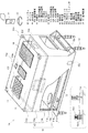
図1は、本発明の一実施例であるセーフティボックス1Aを示した一部切り欠き斜視図である。セーフティボックス1Aは、略直方体の本体筐体10を有する。本体筐体10は、セーフティボックスの筐体として、容易に破損したり破壊されたりしない程度の強度と耐久性を備えている。但し、セーフティボックスとしての重量は、重錘部11に重錘物を充填することにより得られるので、本体筐体10自体はセーフティボックスとしての重量を備える必要はなく、むしろ非使用時に持ち運びし易いように軽量である方が好適である(後述する他の実施例においても同様)。
Embodiments of the present invention will be described below with reference to the drawings showing the embodiments of the present invention.
FIG. 1 is a partially cutaway perspective view showing a
本実施例では、本体筐体10に、重錘部11と収納部12とが一体的に設けられている。重錘部11が下部に、収納部12が上部に設けられ、これらは区画壁13により区画されている。本体筐体10の底板10aは、左右方向に張り出しており、これらの張り出し部分に固定杭19を通して砂浜や地面に固定することにより、さらに移動困難とすることができる(後述する他の実施例においても同様)。
In the present embodiment, the
重錘部11は、本体筐体10の一部を形成する重錘部筐体11aと、重錘部筐体11aにより四方の側面を囲まれた重錘部空間11bと、充填口11c及び排出口11dとを備えている。重錘部空間11bは重錘物を収納するための空間である。重錘物は、例えば、水、海水、砂、石等であり、アウトドアで容易に入手できるものを利用する。図示の例では、重錘部空間11bの上面を形成する区画壁13上に充填口11cである開口が設けられ、重錘部空間11bの下面を形成する本体筐体10の底板10aに排出口11dである開口が設けられている。充填口11c及び排出口11dの各面上での位置、形状及び大きさは、図示の例に限定されない。重錘物が液体の場合に漏出しないように、重錘部筐体11a、区画壁13、充填口11c及び排出口11dは防水性及び密閉性を具備することが好適である。
The
収納部12は、本体筐体10の一部を形成する収納部筐体12aと、収納部筐体12aで囲まれた収納部空間12bと、収納部空間12bを閉鎖するための開閉可能な収納部蓋12cとを備えている。収納される対象物品は、例えば、金銭や携帯電話等の貴重品である。収納部蓋12cは、蝶番12dにより開閉される。収納部蓋12cを閉状態に保持するための電気錠14を構成する各部品が収納部蓋12cと収納部筐体12aのそれぞれに取り付けられている。電気錠14は、手動ではなく電気的に施錠及び解錠される。電気錠14は、モーター式、ソレノイド式、電磁石式等の公知のいずれの種類でもよい。
The
制御装置17は、電気錠14の施錠及び解錠を制御する信号を電気錠14に送る(配線の図示は省略)。制御装置17の操作部を介して所定の情報を入力することにより電気錠14を施錠又は解錠することができる。図示の例では、制御装置17はテンキーボードを操作部として具備し、例えば、施錠及び解錠の際に所定のパスワードを入力する。生体認証方式でもよいが、パスワード方式は低コストである点で好適である。
The
制御装置17は、電気錠14を制御するのみでなく、後述する種々のセンサや警告装置の設定及び制御も行う機能を備えていてもよい。そのために、制御装置17は、簡易プログラムを設定可能なプログラマブルコントローラを内蔵する。また、制御装置17は、アウトドアで使用されるため防水性を有することが好適であり、例えばタッチパネルとしたり、防水用カバーを設けたりしてもよい。タッチパネルのように比較的大きな画面を備えている場合は、画面上に写真や動画を表示可能となる。また、音声出力装置(後述する警報器にも兼用してよい)を備え、音楽や音声を出力可能としてもよい。
The
重錘部11に重錘物を充填する場合は、収納部蓋12cを開き、収納部空間12bの底面にある充填口11cを開いて充填する。例えば、水の場合はホースを用いてもよく、砂の場合は漏斗のような器具を用いてもよい。重錘物を排出する場合は、本体筐体10を横倒しにし、本体底面の排出口11dを開いて排出させる。セーフティボックス1Aの使用時に、悪意の有る者によって開けられて重錘物を排出させられないように、充填口11c及び排出口11dは外観上視認できない箇所及び操作し難い箇所に設けることが、好適である。
When filling the
好適には、本体筐体10が動かされた際の振動を検知する振動センサ15bと、振動センサ15bが検知することに応じて作動する音響的又は視覚的な警報装置とを、本体筐体10に取り付けることが好適である。振動センサ15bの取付位置は、適切な位置であればよい。警報装置は、例えば、アラームを鳴らす警報器16aや、点滅発光する警報灯16bである。なお、振動センサ15bの感度並びに各警報装置の警報の程度、種類及び持続時間等を、制御装置17の操作部により設定可能としてもよい。
Preferably, the
また、好適には、本体筐体10から所定の距離内に接近した人間を検知する人感センサ15aと、人感センサ15aが検知することに応じて作動する音響的又は視覚的な警報装置とを、本体筐体10に取り付けることが好適である。振動センサ15bの取付位置は、適切な位置であればよい。警報装置は、上記の警報器16a、警報灯16bを兼用できる。なお、人感センサ15aの感度並びに各警報装置の警報の程度、種類及び持続時間等も、制御装置17の操作部により設定可能としてもよい。
Preferably, a
さらに、センサの別の実施例として、リミットスイッチ15cを本体筐体の底板10aに取り付けてもよい。図1の左下の枠囲み内に、リミットスイッチ15cの作動状況を概略的に示す。本体筐体の底板10aが地面に接している状態では、リミットスイッチ15cの検知ロッド15c2がスプリングを圧縮しており、接点15c1は開状態である。本体筐体が持ち上げられて底板10aが地面から離れると、検知ロッド15c2がスプリングにより押し出され、接点15c1が閉状態となる。リミットスイッチ15cは、制御装置17と連係しており、接点15c1の開閉は制御装置により検知される。制御装置17は、リミットスイッチ15cからの信号を検知すると、上記の警報装置を作動させる。なお、リミットスイッチ15cは図示の例に限られず、公知の種々のタイプを利用できる。
Furthermore, as another example of the sensor, a
またさらに、リミットスイッチに限られず、本体筐体が移動したことを検知可能なセンサであれば、公知のいずれのタイプのセンサ(例えば、光センサ、超音波センサ等)も利用できる。 Furthermore, the sensor is not limited to a limit switch, and any known type of sensor (for example, an optical sensor, an ultrasonic sensor, or the like) can be used as long as it can detect that the main body casing has moved.
遠隔装置21、22は、使用者が負担を感じずに身につけることができるペンダント型やブレスレット型の小型軽量機器であり、少なくとも受信機能と簡易出力機能とを備えている。簡易出力機能は、例えば、表示画面、LED、アラーム等である。制御装置17は、本体筐体10から離隔した遠隔装置21、22と無線通信可能である。例えば、制御装置17は、警報装置16a、16bが作動したことに応じて遠隔装置21、22に対してその作動を通知する信号を送信する。遠隔装置21、22は、この信号を受信すると簡易出力装置に出力する。例えば、発光したりアラームを鳴らしたりする。これにより、使用者は異変の発生を知ることができる。
The
また、遠隔装置21、22は、制御装置17の遠隔操作キーとしての機能を備えていてもよい。この場合、遠隔装置21、22は、送信機能と簡易入力機能とを備える。簡易入力機能は、例えば、押しボタンである。そして、制御装置17は、遠隔装置21、22から所定の信号を受信したことに応じて電気錠14の施錠又は解錠を制御する。この機能は、例えば、使用者が制御装置17の操作部にパスワードを入力し終えてセーフティボックスから遠ざかる際に遠隔装置21、22を用いて施錠したり、使用者が施錠されているセーフティボックスに近づく際に遠隔装置21、22を用いて解錠したりするために用いられる。
The
このように、制御装置17と遠隔装置21、22は、一方向又は双方向の通信を行えるようにする。一方向のみの通信機能は低コストである。双方向の通信機能を備えることにより、多様な利用形態が可能となる。
As described above, the
遠隔装置21、22のさらに別の利用例として、セーフティボックスの各種機器の機能に異常が発生したときに、遠隔装置21、22に対してそれを知らせる信号を送ってもよい。例えば、制御装置17のCPUエラーや電源電圧低下等である。なお、この機能異常を知らせる信号は、制御装置17から自動で送信されるのみでなく、セーフティボックスの設置場所にいる関係者が、制御装置17を手動操作して送信できるようにしてもよい。
As another example of using the
また、遠隔装置21、22のさらに別の利用例として、遠隔装置21、22の使用者から制御装置17に対して何らかの信号(例えば、救助要請信号)を送信できるようにする。
As another example of using the
さらに、図示しないが、警報装置16a、16bが作動したことに応じて所定の信号の発信を開始する発信器を、本体筐体10に取り付けることが好適である。発信器が持続的に発信する信号は、遠隔装置21、22又は図示しない所定の外部受信機により受信可能とする。このような発信器により、セーフティボックスが持ち去られた際に位置を探索する手掛かりを得ることができる。
Further, although not shown, it is preferable that a transmitter that starts transmission of a predetermined signal in response to the activation of the
電気錠14、制御装置17、各種センサ15a、15b及び警報装置16a、16b等のうち、電源を必要とする機器のために太陽電池18を備えることが好適である。なお、太陽電池18に替えて通常の電池を電源としてもよい。
Among the
図1の実施例における各種センサ15a、15b及び警報装置16a、16b等は、後述する他の実施例では説明を省略するが、他の実施例においても同様に取付けることができる。
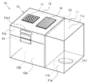
図2は、本発明の別の実施例であるセーフティボックス1Bを示した斜視図である。図1の実施例と同じ構成要素については、同じ符号で示している。
FIG. 2 is a perspective view showing a
セーフティボックス1Bでは、重錘部11と収納部12が上下方向ではなく左右方向に並設されている。重錘部11への重錘物の充填及び排出のための開口は、底面の充填排出口11fである。この場合、1つの開口が充填及び排出に兼用されている(他の実施例でも同様に、充填口と排出口を兼用してもよい)。重錘物の充填及び排出は、セーフティボックス1Bの向きを替えて行う。収納部12の収納部蓋12cを開閉するための取っ手凹部12c1が設けられている(他の実施例でも同様に、収納部蓋12cに適宜の取っ手を設けてもよい)。
In the
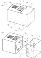
図3(a)は、本発明のさらに別の実施例であるセーフティボックス1Cの連結状態を示した斜視図であり、(b)は分離状態を示した斜視図である。図1の実施例と同じ構成要素については、同じ符号で示している。 FIG. 3A is a perspective view showing a connected state of a safety box 1C which is still another embodiment of the present invention, and FIG. 3B is a perspective view showing a separated state. The same components as those in the embodiment of FIG. 1 are denoted by the same reference numerals.
セーフティボックス1Cは、重錘部11と収納部12が左右に並設されているが、重錘部11と収納部12を連結分離可能である。すなわち、収納部筐体12a重錘部筐体11aとは、互いに連結したり、分離したりできる。
In the safety box 1C, the
図3(b)の分離状態の斜視図に示すように、収納部12の収納部蓋12cは、収納部筐体12aの側面に設けられている。この側面は、収納部筐体12aと重錘部筐体11aの連結状態における連結面12eに相当する。連結状態においては、収納部筐体12aの連結面12eと重錘部筐体11aの連結面11eの各々の全面が互いに当接する。すなわち、連結状態においては、収納部蓋12cは外面には全く露出せず、視認することも触れることもできない。この収納部蓋12c自体には、直接的に施錠するための電気錠は設けられていない。但し、収納部蓋12cは、独りでに開いたりしない程度の係止手段(図示せず)は備えている。
As shown in the perspective view of the separated state in FIG. 3B, the
電気錠14は、収納部筐体12aと重錘部筐体11aとを連結状態に保持するために設けられている。具体的には、電気錠14を構成する各部品が、収納部筐体12aの連結面12eと重錘部筐体11aの連結面11eのそれぞれに取り付けられている。図示の例では、2カ所に電気錠14を設けているが、これらは連動し、いずれも制御装置17により施錠及び解錠を制御される。このように、重錘部11と収納部12が連結分離可能なセーフティボックス1Cにおいても、電気錠14が収納部蓋12cを閉状態に保持するために機能する点では、上述の図1及び図2の実施例と同様である。つまり、電気錠14は、収納部筐体12aと重錘部筐体11aとを連結状態に保持すると同時に収納部蓋12cを閉状態に保持する役割を果たしている。
The
さらに、重錘部11に重錘物を充填する充填口11c及び排出する排出口11dも、重錘部筐体11aの連結面11e上に設けられている。これにより、連結状態においては、充填口11c及び排出口11dの双方とも外部から視認できず触れることもできなくなる。
Further, a filling
重錘部11に重錘物を充填する場合は、重錘部11と収納部12とを分離した状態で、重錘部筐体11aの連結面11eにある充填口11cを開いて充填する。また、排出する場合も分離した状態で排出口11dを開いて排出する。なお、充填口11cと排出口11dを1つの開口で兼用してもよい。この場合、重錘部11への重錘物の充填と、収納物12への対象物品の収納を、分離状態で別個に行うことができるので、取り扱いが容易で便利である。
When the
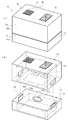
図4(a)は、本発明のさらに別の実施例であるセーフティボックス1Dの連結状態を示した斜視図であり、(b)は分離状態を示した斜視図である。図1の実施例と同じ構成要素については、同じ符号で示している。 FIG. 4A is a perspective view showing a connected state of a safety box 1D which is still another embodiment of the present invention, and FIG. 4B is a perspective view showing a separated state. The same components as those in the embodiment of FIG. 1 are denoted by the same reference numerals.
図4(b)に示すように、セーフティボックス1Dは、図3のセーフティボックス1Cと同様に重錘部11と収納部12を連結分離可能である。但し、セーフティボックス1Dでは、重錘部11と収納部12が上下方向に重ねられて配置されている。収納部筐体12aの収納部蓋12cは、収納部筐体12aの底面である連結面12e上に設けられている。収納部12に対象物品を収納する際には、収納部蓋12cのある面を横又は上に向けて開閉する。収納部蓋12c自体には、直接的に施錠するための電気錠は設けられていない。但し、収納部蓋12cは、下向きとなっても独りでに開いたりしない程度の係止手段(図示せず)は備えている。
As shown in FIG. 4B, the safety box 1D can connect and separate the
また、重錘部11の充填排出口11fは、重錘部筐体11aの上面である連結面11e上に設けられている。充填排出口11fは、充填口と排出口を兼ねている。
Further, the filling / discharging
電気錠14を構成する各部品は、収納部筐体12aの下面である連結面12e及び重錘部筐体11aの上面である連結面11eのそれぞれに取り付けられている。図4のセーフティボックス1Dも図3のセーフティボックス1Cと同様に、電気錠14は、収納部筐体12aと重錘部筐体11aとを連結状態に保持すると同時に収納部蓋12cを閉状態に保持する役割を果たしている。
Each component constituting the
以上述べた各実施例において、セーフティボックスの外観は、制御装置等の外面に露出した機器をカバーで隠したり、通常のクーラーボックスに見えるようにしたりすることが好適である。 In each of the embodiments described above, it is preferable that the appearance of the safety box is such that a device exposed on the outer surface of the control device or the like is covered with a cover, or is made visible as a normal cooler box.
本発明は、以上に説明した実施例に限定されず、その原理を用いた形態のセーフティボックスであれば本発明の範疇に含まれる。 The present invention is not limited to the embodiments described above, and any safety box that uses the principle is included in the scope of the present invention.
1A、1B、1C、1D:セーフティボックス
10:本体筐体
10a:筐体底板
11:重錘部
11a:重錘部筐体
11b:重錘部空間
11c:充填口
11d:排出口
11e:連結面
11f:充填排出口
12:収納部
12a:収納部筐体
12b:収納部空間
12c:収納部蓋
12d:蝶番
12e:連結面
13:区画壁
14:電気錠
15a:人感センサ
15b:振動センサ
15c:リミットスイッチ
16a:警報器
16b:警報灯
17:制御装置
18:太陽電池
19:固定杭
21,22:遠隔装置
1A, 1B, 1C, 1D: Safety box 10:
Claims (8)
前記重錘部(11)は、前記本体筐体(10)の一部を形成する重錘部筐体(11a)と、前記重錘部筐体(11a)で囲まれ重錘物を収納するための重錘部空間(11b)と、前記重錘部空間(11b)内に重錘物を充填又は排出するための開口(11c,11d)と、を備え、
前記収納部(12)は、前記本体筐体(10)の一部を形成する収納部筐体(12a)と、前記収納部筐体(12a)で囲まれ対象物品を収納するための収納部空間(12b)と、前記収納部空間(12b)を閉鎖するための開閉可能な収納部蓋(12c)と、前記収納部蓋(12c)を閉状態に保持するための電気錠(14)と、所定の情報を入力されることにより前記電気錠(14)の施錠及び解錠を制御する制御装置(17)と、を備えたことを特徴とするセーフティボックス。 It has a main body housing (10) provided with a weight part (11) and a storage part (12),
The weight portion (11) is surrounded by the weight portion housing (11a) forming a part of the main body housing (10) and the weight portion housing (11a), and stores a weight object. A weight space (11b) for opening, and an opening (11c, 11d) for filling or discharging a weight in the weight space (11b),
The storage section (12) includes a storage section casing (12a) that forms a part of the main body casing (10), and a storage section that is enclosed by the storage section casing (12a) and stores a target article. A space (12b), an openable / closable storage lid (12c) for closing the storage space (12b), and an electric lock (14) for holding the storage lid (12c) in a closed state And a control device (17) for controlling the locking and unlocking of the electric lock (14) by inputting predetermined information.
Priority Applications (3)
| Application Number | Priority Date | Filing Date | Title |
|---|---|---|---|
| JP2011044602A JP5830254B2 (en) | 2011-03-02 | 2011-03-02 | Safety box |
| CN2012100295598A CN102654011A (en) | 2011-03-02 | 2012-02-10 | Safety box |
| US13/370,660 US8573140B2 (en) | 2011-03-02 | 2012-02-10 | Safety box |
Applications Claiming Priority (1)
| Application Number | Priority Date | Filing Date | Title |
|---|---|---|---|
| JP2011044602A JP5830254B2 (en) | 2011-03-02 | 2011-03-02 | Safety box |
Publications (2)
| Publication Number | Publication Date |
|---|---|
| JP2012180687A true JP2012180687A (en) | 2012-09-20 |
| JP5830254B2 JP5830254B2 (en) | 2015-12-09 |
Family
ID=46729729
Family Applications (1)
| Application Number | Title | Priority Date | Filing Date |
|---|---|---|---|
| JP2011044602A Expired - Fee Related JP5830254B2 (en) | 2011-03-02 | 2011-03-02 | Safety box |
Country Status (3)
| Country | Link |
|---|---|
| US (1) | US8573140B2 (en) |
| JP (1) | JP5830254B2 (en) |
| CN (1) | CN102654011A (en) |
Families Citing this family (14)
| Publication number | Priority date | Publication date | Assignee | Title |
|---|---|---|---|---|
| USD339928S (en) * | 1991-05-23 | 1993-10-05 | John Caldwell | Chair |
| US20130025511A1 (en) * | 2011-07-25 | 2013-01-31 | Timothy Eugene Maxwell | Handgun safe |
| US10329830B2 (en) * | 2012-03-06 | 2019-06-25 | Robert Michael Peck | Portable security box with a solar panel and improved lock that attaches to a fixed object to secure valuables |
| US9732550B2 (en) | 2012-08-10 | 2017-08-15 | Coolsafe Enterprises Inc. | Storage assembly having user-accessible compartments categorized by different levels of user access |
| US20150000571A1 (en) * | 2013-06-27 | 2015-01-01 | Adie, LLC | Portable lock box |
| US9075906B2 (en) * | 2013-06-28 | 2015-07-07 | Elwha Llc | Medical support system including medical equipment case |
| US9838645B2 (en) | 2013-10-31 | 2017-12-05 | Elwha Llc | Remote monitoring of telemedicine device |
| WO2015104649A1 (en) * | 2014-01-08 | 2015-07-16 | Gigliotti Filippo | Safe box for beach umbrella |
| JP2017118375A (en) * | 2015-12-25 | 2017-06-29 | 京セラ株式会社 | Electronic equipment and sound output control method |
| US10415298B2 (en) * | 2016-02-16 | 2019-09-17 | Keymaster Solutions, Llc | Lock box assembly |
| WO2019033045A1 (en) * | 2017-08-10 | 2019-02-14 | Beachsafe Llc | Portable beach safe |
| USD880103S1 (en) * | 2019-09-05 | 2020-03-31 | Clevermade, Llc | Secured container |
| USD880102S1 (en) * | 2019-09-05 | 2020-03-31 | Clevermade, Llc | Secured container |
| USD912365S1 (en) * | 2020-09-23 | 2021-03-02 | Shaodong Shen | Safety box for pistol |
Citations (5)
| Publication number | Priority date | Publication date | Assignee | Title |
|---|---|---|---|---|
| US5199361A (en) * | 1991-08-19 | 1993-04-06 | Robinson Milton W | Beach safety anchor security system |
| US6113268A (en) * | 1998-10-22 | 2000-09-05 | Thompson; George W. | Weighted carrying case |
| JP2004129706A (en) * | 2002-10-08 | 2004-04-30 | Takeshi Shibuya | Portable storage body and theft preventing method therefor |
| JP2005312779A (en) * | 2004-04-30 | 2005-11-10 | Matsushita Electric Ind Co Ltd | Portable home delivery box |
| JP2006502332A (en) * | 2002-08-15 | 2006-01-19 | プロアック・アンパルトセルスカブ | Safety box for storing personal valuables, safety anchors for fixing the safety box, and safety fasteners for fixing various other objects |
Family Cites Families (16)
| Publication number | Priority date | Publication date | Assignee | Title |
|---|---|---|---|---|
| FR2479765A1 (en) * | 1980-04-02 | 1981-10-09 | Guibert Philippe | METHOD OF PROTECTION AGAINST THE FLIGHT OF CYCLES AND MOTORCYCLES USING A CHEST |
| CN2032238U (en) * | 1988-05-30 | 1989-02-08 | 孔清华 | Wall built-in domestic safe |
| JPH0810022A (en) | 1994-07-01 | 1996-01-16 | Noriko Tsuji | Waterproof marine poach |
| KR100263034B1 (en) * | 1995-12-02 | 2000-08-01 | 김지태 | Intelligent safety |
| US5778805A (en) * | 1996-10-25 | 1998-07-14 | Green; John Richard | Vehicle security vault with electronic lock |
| US5936544A (en) * | 1997-09-30 | 1999-08-10 | Pittway Corporation | Wireless access system |
| US6318134B1 (en) * | 1998-07-14 | 2001-11-20 | Mossberg Safe Systems, Inc. | Safe locking mechanism |
| DE10217903C1 (en) * | 2002-04-22 | 2003-10-02 | Kendro Lab Prod Gmbh | Safety work station, for microbiological samples, has working chamber surrounded by housing and safety monitoring system having processor which couples measured data determined during operation of work station |
| US7116224B2 (en) * | 2002-10-08 | 2006-10-03 | Mickler Kerry L | Method and apparatus for securing firearms and other valuables in an alarm protected facility |
| MX2007009048A (en) * | 2005-01-27 | 2007-12-07 | Brush & Co John D | System and method for administering access to an interior compartment of an enclosure. |
| US7961914B1 (en) * | 2005-07-12 | 2011-06-14 | Smith Robert J D | Portable storage apparatus with integral biometric-based access control system |
| CN2934522Y (en) * | 2006-04-30 | 2007-08-15 | 朱培立 | Built-in-wall type personal safe for collective dormitory |
| GB0707928D0 (en) * | 2007-04-25 | 2007-05-30 | Delivery Works Ltd | Delivery system |
| CN201401095Y (en) * | 2009-05-20 | 2010-02-10 | 李怀周 | All-steel fireproofing safety box |
| US8201426B2 (en) * | 2010-01-05 | 2012-06-19 | Heim Jeffrey R | System, method and apparatus for securing valuables |
| CN101975010A (en) * | 2010-07-29 | 2011-02-16 | 无锡滨达工业创意设计有限公司 | Voice identification safety box |
-
2011
- 2011-03-02 JP JP2011044602A patent/JP5830254B2/en not_active Expired - Fee Related
-
2012
- 2012-02-10 CN CN2012100295598A patent/CN102654011A/en active Pending
- 2012-02-10 US US13/370,660 patent/US8573140B2/en not_active Expired - Fee Related
Patent Citations (5)
| Publication number | Priority date | Publication date | Assignee | Title |
|---|---|---|---|---|
| US5199361A (en) * | 1991-08-19 | 1993-04-06 | Robinson Milton W | Beach safety anchor security system |
| US6113268A (en) * | 1998-10-22 | 2000-09-05 | Thompson; George W. | Weighted carrying case |
| JP2006502332A (en) * | 2002-08-15 | 2006-01-19 | プロアック・アンパルトセルスカブ | Safety box for storing personal valuables, safety anchors for fixing the safety box, and safety fasteners for fixing various other objects |
| JP2004129706A (en) * | 2002-10-08 | 2004-04-30 | Takeshi Shibuya | Portable storage body and theft preventing method therefor |
| JP2005312779A (en) * | 2004-04-30 | 2005-11-10 | Matsushita Electric Ind Co Ltd | Portable home delivery box |
Also Published As
| Publication number | Publication date |
|---|---|
| CN102654011A (en) | 2012-09-05 |
| US20120222589A1 (en) | 2012-09-06 |
| JP5830254B2 (en) | 2015-12-09 |
| US8573140B2 (en) | 2013-11-05 |
Similar Documents
| Publication | Publication Date | Title |
|---|---|---|
| JP5830254B2 (en) | Safety box | |
| US11694527B2 (en) | Systems and methods for protecting retail display merchandise from theft | |
| US10264865B2 (en) | Luggage | |
| US20230394937A1 (en) | System and method for calibrating a wireless security range | |
| US7855642B2 (en) | Portable motion-detecting alarm with remote notification | |
| US20130193005A1 (en) | Portable security and protection enclosures | |
| US20200048932A1 (en) | Transportable Device for Preventing a Loss of a Movable Object | |
| CN110419212B (en) | Portable device with built-in security system | |
| US9907377B2 (en) | Security system for tracking movable objects | |
| RU2616537C2 (en) | Multifunctional devices of anti-theft protection | |
| KR20040044851A (en) | Portable security device | |
| WO2019084129A1 (en) | Anti-theft beach bag | |
| US10373455B1 (en) | Theft detection system | |
| US9816295B1 (en) | Emergency entry control system | |
| US20150314753A1 (en) | Portable, self-contained anti-theft alarm system for the cargo compartment of a vehicle | |
| US10577822B1 (en) | Secure strongbox with illumination | |
| WO2015188704A1 (en) | Anti-theft device | |
| JP3235404U (en) | Locking / unlocking response system for locking / unlocking objects using smartphones | |
| KR20110001107U (en) | Various function bag | |
| KR20120132447A (en) | Portable safety box | |
| KR102255326B1 (en) | Digital Photo Frame for ossuary with charging function normally using your mobile phone and theft prevention | |
| KR101954095B1 (en) | Electronic key | |
| JP2023056724A (en) | Locking/unlocking response system of locked/unlocked object using smart phone | |
| KR200198574Y1 (en) | Anti-theft device for valuables lockers | |
| JP2020135575A (en) | Article management system |
Legal Events
| Date | Code | Title | Description |
|---|---|---|---|
| A621 | Written request for application examination |
Free format text: JAPANESE INTERMEDIATE CODE: A621 Effective date: 20140218 |
|
| A977 | Report on retrieval |
Free format text: JAPANESE INTERMEDIATE CODE: A971007 Effective date: 20140904 |
|
| A131 | Notification of reasons for refusal |
Free format text: JAPANESE INTERMEDIATE CODE: A131 Effective date: 20140916 |
|
| A521 | Request for written amendment filed |
Free format text: JAPANESE INTERMEDIATE CODE: A523 Effective date: 20141107 |
|
| A131 | Notification of reasons for refusal |
Free format text: JAPANESE INTERMEDIATE CODE: A131 Effective date: 20150331 |
|
| A521 | Request for written amendment filed |
Free format text: JAPANESE INTERMEDIATE CODE: A523 Effective date: 20150401 |
|
| TRDD | Decision of grant or rejection written | ||
| A01 | Written decision to grant a patent or to grant a registration (utility model) |
Free format text: JAPANESE INTERMEDIATE CODE: A01 Effective date: 20150929 |
|
| A61 | First payment of annual fees (during grant procedure) |
Free format text: JAPANESE INTERMEDIATE CODE: A61 Effective date: 20151026 |
|
| R150 | Certificate of patent or registration of utility model |
Ref document number: 5830254 Country of ref document: JP Free format text: JAPANESE INTERMEDIATE CODE: R150 |
|
| R250 | Receipt of annual fees |
Free format text: JAPANESE INTERMEDIATE CODE: R250 |
|
| LAPS | Cancellation because of no payment of annual fees |