JP2012170904A - Dust-collecting filter and dust-collecting apparatus having the same filter - Google Patents
Dust-collecting filter and dust-collecting apparatus having the same filter Download PDFInfo
- Publication number
- JP2012170904A JP2012170904A JP2011036143A JP2011036143A JP2012170904A JP 2012170904 A JP2012170904 A JP 2012170904A JP 2011036143 A JP2011036143 A JP 2011036143A JP 2011036143 A JP2011036143 A JP 2011036143A JP 2012170904 A JP2012170904 A JP 2012170904A
- Authority
- JP
- Japan
- Prior art keywords
- filter
- dust
- electret
- air volume
- air
- Prior art date
- Legal status (The legal status is an assumption and is not a legal conclusion. Google has not performed a legal analysis and makes no representation as to the accuracy of the status listed.)
- Pending
Links
Images


Abstract
Description
本発明は、工場等の作業現場から発生する粉塵(ダスト)やヒュームを捕集する集塵機や、その他クリーナーや脱臭装置といった各種の集塵装置等に使用して好適な集塵用フィルタと、そのフィルタを備えた集塵装置に関するものである。 The present invention relates to a dust collection filter suitable for use in various dust collectors such as a dust collector that collects dust and fume generated from a work site such as a factory, and other cleaners and deodorizers, and the like. The present invention relates to a dust collector equipped with a filter.
従来の一般的な集塵用のフィルタは、濾過面積を広くするために、例えば特許文献1に見られるように、フィルタ面を多数のヒダがフィルタの長手方向に幾重にも重なるように、断面略蛇腹形状(ジグザグ形状・アコーディオン形状等)に形成されていた。
In order to increase the filtration area, the conventional general dust collection filter has a cross section so that a large number of pleats overlap each other in the longitudinal direction of the filter, as seen in
また、高捕集効率と低圧力損失を維持する集塵用フィルタとして、例えば特許文献2に見られるように、表面電荷密度と繊度が異なる2層に積層したエレクトレット化された素材から成るフィルタも存在する。
Further, as a dust collection filter that maintains high collection efficiency and low pressure loss, for example, as seen in
一方、例えば特許文献3に見られるように、定風量運転を実現するファジイコントロールシステムを搭載したインテリジェント機能を有する最近の集塵機では、吸引風量を風速計とコンピュータで常時監視し、吸引風量の増減を検知すると、吸塵用ファンの回転をファジイ制御して最適な吸引風量(設定風量)に自動修正するように構成されている。
On the other hand, as seen in
ところが、上記特許文献1に記載の表面略蛇腹状の集塵用フィルタを用いた集塵装置を使用する場合において、一般的な含塵空気を捕集する場合については問題ないが、例えばレーザー加工時(シールやラベルのマーキング、カッティング等)やはんだ付け作業時に発生するヒュームを捕集する場合には、ヒュームは非常に細かい粒子径を含んでいるため、それらがフィルタ濾過材に悪影響を及ぼして、早期にフィルタの目詰まりが発生してしまう問題があった。
However, in the case of using the dust collector using the dust collecting filter having a substantially bellows-like surface described in
特に、高濃度のヒュームを吸引した場合においては、その傾向が顕著に見られ、また、目詰まりが発生しやすい箇所としては、フィルタ各層の各段内径部や、フィルタ各段のフィルタ内面(濾過面)における蛇腹の濾過面が接近している箇所であり、そこから目詰まりが徐々に広まっていく傾向が見られた。 In particular, when high-concentration fumes are aspirated, the tendency is noticeable, and clogging is likely to occur in areas where the inner diameter of each stage of the filter and the inner surface of the filter (filter The surface of the bellows is close, and clogging tends to spread gradually from there.
一方、特許文献2に記載の積層エレクトレットフィルタにおいては、電荷密度に対してのフィルタ繊維の繊維径を規定しているが、例えば、フィルタ繊維の繊維径を太く(太繊度)して、フィルタ繊維の密度が高い濾過材を濾過面側の表層部に用いた場合には、捕集した粗い粒子の塵埃がフィルタ繊維の濾過面の表層部に先に付着することで、通気度を充分に確保することができず、早期に目詰まりが発生してしまう問題があった。
On the other hand, in the multilayer electret filter described in
加えて、特に積層フィルタにおいては、ヒュームを含んだ含塵空気を捕集する場合、含塵空気中には非常に細かい(0.3μm程度)粒子から、比較的大きな粒子( 10μm程度)まで広範囲の粒子が混入し、且つ、比較的大きな粒子( 10μm程度)の体積割合が大きいため、前記特許文献2に記載のようなフィルタ繊維の繊維径の選定だけでは、それら全ての粒子径の塵埃を捕集するのに適した濾過材を選定することは困難であった。
In addition, especially in multilayer filters, when dust-containing air containing fume is collected, the dust-containing air has a wide range from very fine particles (about 0.3 μm) to relatively large particles (about 10 μm). In addition, since the volume ratio of relatively large particles (about 10 μm) is large, the selection of the fiber diameter of the filter fiber as described in
更に、前記特許文献3では、吸引空気量の増減に応じて、吸塵用ファンの回転を制御して、最適な吸引風量(設定風量)に自動修正するようにしているが、一般的には、工程毎の含塵空気中に含まれる含塵量は異って変化するため、吸引空気量の増減に応じて、吸塵用ファンの回転を制御して吸引風量を変化させただけでは、含塵濃度の増減に対応することはできず、例えば、吸引空気量が少なく吸引空気量の塵埃量が非常に多い場合においては、設定風量となるように吸引風量を加速回転して吸引空気量を増加させているが、含塵濃度が非常に高いため、フィルタに濾過性能以上の負荷が掛かってしまい、その結果、早期に目詰まりが生じてしまう問題があった。
Furthermore, in
従って本発明の技術的課題は、含塵空気中に粒子径が非常に細かいヒュームを含んでいて、而もこのヒュームが高濃度である含塵空気を吸引した場合においても、早期に目詰まりが発生しないように工夫した集塵用フィルタと、この集塵用フィルタを搭載した集塵装置を提供することである。 Therefore, the technical problem of the present invention is that fume having a very small particle diameter is contained in the dust-containing air, and even when dust-containing air having a high concentration of the fume is sucked, clogging is early. It is an object of the present invention to provide a dust collecting filter devised so as not to be generated, and a dust collecting device equipped with the dust collecting filter.
(1) 上記の技術的課題を解決するために、本発明の請求項1に係る集塵用フィルタは、繊維層が異なる2枚又は2枚以上の複数枚の濾過材を積層させることによって構成されていて、当該繊維層はその上流側、即ち、濾過面側から少なくともエレクトレット濾過材と、高性能濾過材を用いて積層構造に構成され、且つ、両濾過材のフィルタ繊維の密度が、エレクトレット濾過材よりも高性能濾過材の方が高く構成されていることを特徴としている。
(1) In order to solve the above technical problem, the dust collection filter according to
(2) また、本発明の請求項2に係る集塵用フィルタは、繊維層が3枚の濾過材を積層させることによって構成されていて、当該繊維層はその上流側、即ち、濾過面側から少なくとも第1エレクトレット濾過材と、第2エレクトレット濾過材、及び、高性能濾過材を用いて構成され、且つ、これ等3層の濾過材のフィルタ繊維の密度が、第1エレクトレット濾過材、第2エレクトレット濾過材、高性能濾過材の順番に順次高くなるように構成されていることを特徴としている。
(2) Moreover, the filter for dust collection which concerns on
(3) また、本発明の請求項3に係る集塵用フィルタは、前記高性能濾過材が、エレクトレット濾過材を用いて構成されていることを特徴としている。
(3) Moreover, the filter for dust collection which concerns on
(4) また、本発明の請求項4に係る集塵用フィルタは、前記上流側、即ち、濾過面側の繊維層を構成する第1エレクトレット濾過材の目付け量が、他のエレクトレット濾過材の目付け量の2倍以上で、且つ、厚さが3倍以上に構成されていることを特徴としている。
(4) Further, in the dust collecting filter according to
(5) 次に、本発明の請求項5に係る集塵装置は、平面視が略四角形状又は円形状の袋形状を成し、外端部をヒダのように次第に細く形成すると共に、上下両面には含塵空気の通気穴を開口して成る複数のフィルタ単体を、上下の通気穴同士が連通し、且つ、フィルタの長手方向にヒダを幾重にも重なるように複数連設して、これ等複数連設したフィルタ単体のうち、含塵空気の流れ方向に対して最初のフィルタ単体の中央部に開口されている通気穴を含塵空気の吹込口とし、最後のフィルタ単体の底面を通気穴が開口されていない閉塞面とするように構成すると共に、上記複数連設した各フィルタ単体が、繊維層が異なる2枚又は2枚以上の複数枚の濾過材を積層させることによって構成されていて、当該繊維層はその上流側、即ち、濾過面側から少なくともエレクトレット濾過材と、高性能濾過材を用いて積層構造に構成され、且つ、両濾過材のフィルタ繊維の密度が、エレクトレット濾過材よりも高性能濾過材の方が高く構成された集塵用フィルタを用いて構成されていることを特徴としている。
(5) Next, the dust collector according to
(6) また、本発明の請求項6に係る集塵装置は、前記エレクトレット濾過材の濾過面側の四隅に、エレクトレット濾過材間の密着を防止し、且つ、通気性を確保するための通気性部材が介在されていることを特徴としている。
(6) Moreover, the dust collector which concerns on
(7) また、本発明の請求項7に係る集塵装置は、前記各通気穴の端縁が上下外側方向に広がらないように縫着又は固着されていることを特徴としている。 (7) Moreover, the dust collector which concerns on Claim 7 of this invention is sewn or fixed so that the edge of each said vent hole may not spread in the up-down outer direction.
(8) また、本発明の請求項8に係る集塵装置は、前記上下に複数連設したフィルタ単体のうち、その最下端側から数えて複数個のフィルタ単体の内部には、全体を略櫛型状に形成した密着防止板の各長片状の櫛片が夫々介在されていることを特徴としている。
(8) Moreover, the dust collector which concerns on
(9) 更に、本発明の請求項9に係る集塵装置は、集塵機の機体内で、且つ、前記集塵用フィルタより下流側に、濾過風量を測定することができる風量測定手段と、回転数を可変可能なブロワモータと、風量測定手段からの信号によりブロワモータの回転数を可変制御する制御部とを設けると共に、
上記集塵用フィルタより上流側には、含塵空気中の含塵濃度を測定することができる粉塵濃度測定手段を設けて、
上記の制御部は、風量値と粉塵濃度値より単位風量当りの粉塵濃度値、即ち、粉塵濃度を風量で割った値を演算し、
風量を上昇させても単位風量当りの粉塵濃度値が変化しない値を粉塵濃度飽和値として、この粉塵濃度飽和値を維持しつつ、上記風量検出手段から算出される風量値が最小となるように上記ブロワモータの回転数を制御することを特徴としている。
(9) Further, the dust collector according to
On the upstream side of the dust collecting filter, a dust concentration measuring means capable of measuring the dust concentration in the dust-containing air is provided,
The above control unit calculates the dust concentration value per unit air volume from the air volume value and the dust density value, that is, a value obtained by dividing the dust density by the air volume,
The value that the dust concentration value per unit air volume does not change even if the air volume is increased is taken as the dust concentration saturation value, and the air volume value calculated from the air volume detection means is minimized while maintaining this dust concentration saturation value. The number of rotations of the blower motor is controlled.
上記(1)で述べた請求項1に係る集塵用フィルタによれば、高性能濾過材の上流側にエレクトレット濾過材を設けた複層構造に構成したことで、含塵空気中に含まれる様々な粒子径の塵埃を静電気による作用で効果的に捕集することができ、且つ、高性能濾過材との境界面に捕集される粒子を減らすことで、高性能濾過材に負担を掛けないことにより、高捕集効率を実現しながらフィルタ濾過材の寿命を伸ばすことができる。更に、高性能濾過材よりも密度が低いエレクトレット濾過材を使用したことで、圧力損失を低く抑えることができて、吸引源となるブロアなどに与える負担を可及的に少なくすることができる。
According to the dust collecting filter according to
上記(2)で述べた請求項2に係る集塵用フィルタによれば、上流側(濾過面側)からフィルタ繊維の密度の小さい順に第1エレクトレット濾過材、第2エレクトレット濾過材、及び、高性能濾過材と3層に積層することにより、含塵空気中に含まれるヒュームが一つの濾過材に集中して捕集されず、しかも徐々にその絶対量を減少させながら上流側(濾過面側)から下流側に濾過が進むことで、フィルタ全体として捕集効率を確保しつつ、目詰まりし難い構成とした。更に、第1エレクトレット濾過材と高性能濾過材の間に、第2エレクトレット濾過材Bを設けたことで、第1エレクトレット濾過材では捕集が困難な比較的細かい粒子を捕集することができるので、高性能濾過材に負担を掛けずフィルタ濾過材の寿命を伸ばすことができる。
According to the dust collection filter according to
上記(3)で述べた請求項3に係る集塵用フィルタによれば、濾過材の構成が含塵空気中のヒュームを捕集する積層された3層のエレクトレット濾過材であることより、濾材に荷電してエレクトレット化させる製造工程において、積層された3層のエレクトレット濾過材をまとめて荷電することができるので、作業効率が良くて製造コストを低くすることができる。加えて、高性能濾過材をエレクトレット化させたことによって、その静電気力により、更に捕集能力及び捕集したダストの保持力を向上させることができる。
According to the dust collecting filter according to
上記(4)で述べた請求項4に係る集塵用フィルタによれば、第1エレクトレット濾過材の目付量と厚さを、第2、第3のエレクトレット濾過材に比べて請求項4に記載の比率にすることで、含塵空気中に含まれる広範囲(1〜 10μm)の粒子径を第1エレクトレット濾過材で先に捕集・保持可能と成し、より粒子径の細かい塵埃を捕集するための下流側の濾過材に負担を掛けないことで、フィルタの寿命を伸ばすことができる。
According to the dust collecting filter according to
上記(5)で述べた請求項5に係る集塵装置によれば、集塵用フィルタとして、前記(1)で述べた請求項1に係る集塵用フィルタと同一の作用を発揮できると共に、フィルタの全体が断面略蛇腹形状に構成できるため、濾過材が含塵空気の流れ方向に対して斜めに形成されて、濾過流路を長くすることができるから、ダストの捕集効率を向上させることができる。
According to the dust collecting apparatus according to
上記(6)で述べた請求項6に係る集塵装置によれば、介在した通気性部材がエレクトレット濾過材のひだ部の端部間の密着を防止し、通気性が確保されて、エレクトレット濾過材の端部に至るまで有効に機能することを可能とした。更に、上記通気性部材は、第1エレクトレット濾過材よりも圧力損失が小さいので、当該濾過材の捕集性能に影響を与えることはない。
According to the dust collecting apparatus according to
上記(7)で述べた請求項7に係る集塵装置によれば、通気穴の端部(先端部)は、縫着又は固着によって外側(上下側)に拡がらないので、通気性を妨げることはない。 According to the dust collecting apparatus according to claim 7 described in the above (7), the end portion (tip portion) of the vent hole does not expand outward (upper and lower sides) by sewing or fixing, so that air permeability is hindered. There is nothing.
上記(8)で述べた請求項8に係る集塵装置によれば、櫛型状の密着防止板を取付けることによって、第1エレクトレット濾過材の通気穴を形成する端部間の密着を防止し、通気性が確保されて、第1エレクトレット濾過材の端部に至るまで有効に機能することを可能とした。尚、最下端のフィルタ単体から数えて複数個以上に密着防止板を取付ければ、上方のフィルタ単体には、下方側のフィルタ単体、及び密着防止板の重量が掛かり下方側に引張られるので、通気穴を形成する端部が開口することとなる。よって上方のフィルタ単体には、密着防止板を取付ける必要がないので、コストを安く抑えることができる。
According to the dust collector according to
上記(9)で述べた請求項9に係る集塵装置によれば、粉塵飽和濃度に達する必要最小限の風量となるように、ブロワモータの回転数を制御することで、最も集塵効率の高い制御方法を提供することができる。更に、フィルタの濾過性能以上に負荷を掛けることもなく、その結果、早期にフィルタ目詰まりが発生することも防止することを可能にする。
According to the dust collector according to
以上述べた次第で、本発明に係る集塵用フィルタ及びそのフィルタを備えた集塵装置によれば、含塵空気中に粒子径が非常に細かいヒュームを含んでいて、ヒュームが高濃度である含塵空気を吸引した場合においても、早期に目詰まりが発生しないようにフィルタ構造を工夫し、特にフィルタを構成する濾過材の積層順序や目付け量、厚さ、密度が最適となるような値とし、目詰まりが発生しやすい箇所においても改良を加えると共に、更には、含塵空気中の含塵量(含塵濃度)に応じて最適な濾過風量に自動的に制御することにより、フィルタの捕集能力を最大限に有効活用することできて、目詰まりし難く、且つ効率の良い集塵用フィルタ及びこの集塵用フィルタを搭載した集塵装置を提供することができる。 As described above, according to the dust collecting filter and the dust collecting apparatus including the filter according to the present invention, the dust-containing air contains fumes having a very small particle diameter, and the fumes are high in concentration. Even when air containing dust is sucked in, the filter structure is devised so that clogging does not occur at an early stage, and in particular, the order in which the filter media constituting the filter are stacked, the basis weight, the thickness, and the density are optimal. In addition to making improvements even in areas where clogging is likely to occur, the filter air flow is automatically controlled according to the dust content (dust concentration) in the dust-containing air. It is possible to provide a dust collection filter that can effectively use the collection capability to the maximum extent, is less likely to be clogged, and is efficient, and a dust collector equipped with the dust collection filter.
<フィルタ濾過材について>
<濾過材の構成、積層順序>
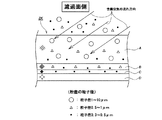
以下に、本発明の実施の形態を図面と共に詳細に説明すると、図1に符号ZKで全体的に示したフィルタ濾過体の構成、積層順序は、繊維層が異なるA〜Dの4層の濾過材によって形成されていて、上流側(濾過面側)から、含塵空気中に含まれる粒子径が1〜10μmを中心に捕集するための繊維層を形成する第1のエレクトレット濾過材Aと、含塵空気中に含まれる粒子径が 0.5〜1μmを中心に捕集するための繊維層を形成するエレクトレット濾過材Bと、含塵空気中に含まれる粒子径が 0.3〜0.5μmを中心に捕集するための繊維層を形成するエレクトレット濾過材Cと、骨材を形成する通気性濾過材Dが積層されている。
<About filter media>
<Configuration of filter media, stacking order>
The embodiment of the present invention will be described below in detail with reference to the drawings. The configuration and stacking order of the filter filter body generally indicated by ZK in FIG. A first electret filter material A which is formed of a material and forms a fiber layer for collecting particles having a particle diameter of 1 to 10 μm as a center from the upstream side (filter surface side) in the dust-containing air; The electret filter medium B for forming a fiber layer for collecting particles with a particle size of 0.5 to 1 μm centered in the dust-containing air, and a particle size of 0.3 to 0 contained in the dust-containing air An electret filter medium C that forms a fiber layer for collecting about 5 μm and an air-permeable filter medium D that forms an aggregate are laminated.
また、高性能濾過材である第3のエレクトレット濾過材Cの上流側に、第1と第2のエレクトレット濾過材A、Bを設けたことで、静電気により含塵空気中に含まれる比較的小さな粒子から大きな粒子(粒子径 0.5〜10μm)までを広範囲に効果的に捕集することができて、第3のエレクトレット濾過材Cに負担を掛けないことにより、高捕集効率を実現しながらフィルタ濾過体ZKの寿命を伸ばすことができる。 In addition, by providing the first and second electret filter media A and B upstream of the third electret filter media C, which is a high-performance filter media, it is relatively small contained in the dust-containing air due to static electricity. High collection efficiency can be achieved by effectively collecting a wide range of particles up to large particles (particle size 0.5 to 10 μm) and not placing a burden on the third electret filter material C. However, the lifetime of the filter body ZK can be extended.
加えて、上記に述べた通り、濾過材A,B,Cは、エレクトレット化された濾過材であることより、濾材に荷電してエレクトレット化させる製造工程において、積層された3層のエレクトレット濾過材A,B,Cをまとめて荷電することができるので、製造コストを低く抑えることができる。 In addition, as described above, since the filter media A, B, and C are electret filter media, the three-layer electret filter media stacked in the manufacturing process in which the filter media is electretized by charging. Since A, B, and C can be charged together, the manufacturing cost can be kept low.
<フィルタ繊維の密度>
実施例でのフィルタ濾過体ZKは、上流側(濾過面側)からフィルタ繊維の密度の小さい順に第1エレクトレット濾過材A、第2エレクトレット濾過材B、第3エレクトレット濾過材Cから成る複数の濾過材を積層することにより、含塵空気中に含まれるヒュームが一つの濾過材に集中して捕集されず、しかも徐々にその絶対量を減少させながら上流側(濾過面側)から下流側に濾過が進むことで、フィルタ全体として捕集効率を確保しつつ目詰まりし難い構成とした。
<Density of filter fiber>
The filter body ZK in the embodiment has a plurality of filtrations composed of the first electret filtration material A, the second electret filtration material B, and the third electret filtration material C in the order of decreasing filter fiber density from the upstream side (filtration surface side). By stacking the materials, the fumes contained in the dust-containing air are not concentrated and collected in one filter material, and while gradually decreasing the absolute amount, from the upstream side (filter surface side) to the downstream side By proceeding with the filtration, the entire filter is configured to prevent clogging while ensuring the collection efficiency.
更に、第1エレクトレット濾過材Aと第3エレクトレット濾過材Cの間に、第2エレクトレット濾過材Bを設けたことで、第1エレクトレット濾過材Aで捕集できなかった比較的大きな粒子や粒子径が0.5〜1μm程度の比較的細かい粒子を捕集することができるので、高性能濾過材である第3エレクトレット濾過材Cに負担を掛けずにフィルタ濾過材A,B,Cの寿命を伸ばすことができる。 Furthermore, by providing the second electret filter material B between the first electret filter material A and the third electret filter material C, relatively large particles and particle diameters that could not be collected by the first electret filter material A Can collect relatively fine particles of about 0.5-1 μm, so that the life of the filter media A, B, C can be increased without imposing a burden on the third electret filter material C, which is a high-performance filter material. Can be stretched.
<濾過材のスペック>
第1エレクトレット濾過材Aの仕様は、目付け量が300 g/m2以上、厚さ3mm以上のものを使用し、実施例では目付け量が315g/m2、厚さ3.7mm、圧力損失15.7Pa、密度85.1×10 3g/m3のものを使用している。
<Specs of filter media>
The specifications of the first electret filter material A are those having a basis weight of 300 g / m 2 or more and a thickness of 3 mm or more. In the examples, the basis weight is 315 g / m 2 , the thickness is 3.7 mm, and the pressure loss is 15 0.7 Pa and density 85.1 × 10 3 g / m 3 are used.
第1エレクトレット濾過材Aを上記の目付け量及び厚さにすることで、含塵空気中に含まれる広範囲(1〜 10μm)の粒子径を捕集・保持可能とし、より粒子径の細かい塵埃を捕集するための下流側の濾過材(濾過材B,C)に負担を掛けないことで、フィルタ寿命を伸ばすことができる。 By making the first electret filter material A have the above-mentioned basis weight and thickness, it is possible to collect and hold a wide range (1 to 10 μm) of particle diameter contained in the dust-containing air, and to collect dust with a finer particle diameter. The filter life can be extended by placing no burden on the downstream filter media (filter media B and C) for collection.
第2エレクトレット濾過材Bの仕様は、目付け量が115 g/m2、厚さ0.9mm、圧力損失25Pa、密度127.8×103g/m3で、その密度は、第1エレクトレット濾過材Aの密度に比べて約1.5倍である。 The specifications of the second electret filter material B are a basis weight of 115 g / m 2 , a thickness of 0.9 mm, a pressure loss of 25 Pa, a density of 127.8 × 10 3 g / m 3 , and the density is the first electret filtration. The density of the material A is about 1.5 times.
第3エレクトレット濾過材Cの仕様は、目付け量が100 g/m2、厚さ0.61mm、圧力損失238Pa、密度163.9×103g/m3で、その密度は第1エレクトレット濾過材Aの密度に比べて約2倍である。尚、第3エレクトレット濾過材Cの捕集効率は、99.999%( JIS Z 8122の測定方法に基づく)であり、HEPAフィルタに相当する高性能濾過材であることがわかる。また、骨材を形成する通気性濾過材Dは、目付け量が60 g/m2、厚さ0.22mm、通気度100CC/cm2・sec、圧力損失25Paであり、通気性に優れた高強度の不織布を使用している。 The specifications of the third electret filter medium C are: the basis weight is 100 g / m 2 , the thickness is 0.61 mm, the pressure loss is 238 Pa, the density is 163.9 × 10 3 g / m 3 , and the density is the first electret filter medium. It is about twice the density of A. In addition, the collection efficiency of the 3rd electret filter medium C is 99.999% (based on the measuring method of JIS Z 8122), and it turns out that it is a high performance filter medium equivalent to a HEPA filter. Further, the air-permeable filter material D forming the aggregate has a weight per unit area of 60 g / m 2 , a thickness of 0.22 mm, an air permeability of 100 CC / cm 2 · sec, and a pressure loss of 25 Pa. A strong nonwoven fabric is used.
<フィルタについて>
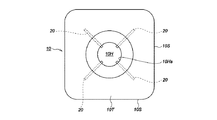
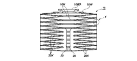
以下に、上述したフィルタ濾過体ZKを用いて構成した本発明に係るフィルタの実施の形態を図面と共に説明すると、図2は本発明が実施されたフィルタの平面図、図3はフィルタの側面図、図4は側面からの断面図であって、これ等の図面において夫々符号10で全体的に示した本発明に係るフィルタは、複数のフィルタ単体10T…を上下縦方向に連設することによって構成されている。即ち、上述した図2、図3、図4に示すように、各フィルタ単体10T…は濾材(濾過体材ZK)を折り曲げ加工することによって、平面視が断面四角形状又は円形状を成し、且つ、上下の幅を比較的薄く形成した袋状に成形されていて、その外端部10Sはヒダ状に細く偏平状に成形されると共に、上下幅を広く造った中央部の上下両面には含塵空気の通気穴10Hを開口形成した構成に造られている。
<About filters>
Hereinafter, an embodiment of a filter according to the present invention configured using the above-described filter filter ZK will be described with reference to the drawings. FIG. 2 is a plan view of the filter in which the present invention is implemented, and FIG. 3 is a side view of the filter. 4 is a cross-sectional view from the side, and the filter according to the present invention generally indicated by
本発明に係るフィルタ10は、以上の如く構成した複数のフィルタ単体10T…を、図3の如く中央の通気穴10H…同士が連通し、且つ、フィルタ10の長手方向(図面では上下方向)に各フィルタ単体10T…のヒダ(外端部10S)が幾重にも重なるように、接着又は縫着等の手段によって連設することによって構成されている。
In the
更に図3において、10K…は上記上下方向に連設した各フィルタ単体10T…の外端部10S…同士の部分、具体的には、四隅の各外端部10S…の部分同士を縦方向に連結した紐体(糸、リボンのような幅広の紐、ワイヤー等)であって、これ等の紐体10K…はフィルタ10の全体を図3のように吊下げ状態(上下伸張状態)にした時には、各フィルタ単体10T…が上下に等間隔に伸張して、重なっていたフィルタ面を上下に開き、各フィルタ単体10T…のフィルタ面を有効利用できるように構成されている。尚、上記紐体10K…の取付け位置は、外端部10Sの角部(隅部)のみに限定されないことは勿論であって、外端部10Sの中間部等、外端部10Sであればいずれの部位であってもよく、図示の位置のみに限定されることはない。
Further, in FIG. 3, 10K... Is a portion between the
<通気性部材について>
また、各フィルタ単体10Tの4隅には、厚さが数十mm(実施例では、約20mm)で、平面視より見て略三角形状の不織布である通気性部材10X…が使用されている。(図5、図6(a)参照。)通気性部材10Xの圧力損失は、前述したエレクトレット濾過材Aの圧力損失(実施例では15.7Pa)よりも十分に低く、通気性に優れた素材を使用しているので、捕集性能に影響を与えることはない。
<Breathable member>
Further, at the four corners of each
実施例では、図6(a)のように、上下の濾過体ZK、ZKを構成する第1エレクトレット濾過材A,Aの間に、通気性部材10Xを挟んだ後、外周を縫製処理している。このように、通気性部材10Xを取付けることによって、第1エレクトレット濾過材A,Aの捕集面同士の密着を防止し、通気性が確保されて、第1エレクトレット濾過材A,Aの端部に至るまで有効に濾過性能が機能することを可能とした。尚、図6(b)のように通気性部材10Xを介在していないと第1エレクトレット濾過材A,Aの内面同士が密着、若しくは非常に接近してしまい、通気性が確保できなくなることが判明した。
In the embodiment, as shown in FIG. 6A, after the air-
<通気穴の端部の処理について>
また、各フィルタ単体10Tの通気穴10Hの端縁部10Ha(内端部)は、外側(上下側)に拡がっていない形状をしていて、実施例では、かがり縫い10HTによって縫製処理されている。即ち、図5並びに図7(a)のように、端縁部10Haをかがり縫い10HTとすることで、端縁部10Ha(先端)が開かず通気性を妨げることはない。例えば、図7(b)のように端縁部10Haが開いている状態で縫製処理10Wした場合には、その開いている箇所にヒューム及び塵埃DSが付着して、次第に成長していくので、それに伴いフィルタ差圧も上昇し、最終的には、開口部10Zが閉塞してしまい、フィルタ10、即ち、フィルタ単体10Tが目詰まりしてしまう。特に、粘着性や付着性の特性を備えたヒューム及び塵埃については、この傾向が顕著に見られる。
<Treatment of the end of the vent hole>
Further, the end edge portion 10Ha (inner end portion) of the
よって、端縁部10Haをかがり縫い10HTで縫製処理することで、端部10Ha(先端)が図7(b)のように開かない形状となり、開口部10Zの通気性を確保しながら、ヒューム及び塵埃の端部10Ha(先端部)への付着を最小限に留めることができて、フィルタ寿命を伸ばすことができる。なお実施例では、かがり縫い10HTによる縫製処理をしているが、例えば、接着、圧着、溶着などの他の方法により、端部が開かないように処理しても構わない。
Therefore, by sewing the edge portion 10Ha with the overlock stitches 10HT, the end portion 10Ha (tip) does not open as shown in FIG. 7B, and the air flow of the
<密着防止板について>
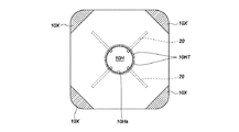
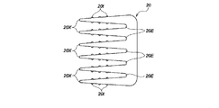
実施例では、第4、図8に示した樹脂製の密着防止板20は、図示のような板状の櫛型形状をしている。櫛歯状の6箇所の長辺部20X…は、等間隔で形成されていて、その間には略V字形状の切り込み20E…が入れられている。平面から見てフィルタ10には、図2に示すように丁度90度間隔で密着防止板20が4箇所取付けられている。実施例では、図4に示す断面図に示す如く、10段のフィルタ単体10T…を形成しているフィルタ10において、最下段より数えて6段までのフィルタ単体10T…に密着防止板20の計6本の長辺状の櫛片20X…が差し込み保持されている。フィルタ単体10T…の内側に長辺状の櫛片20X…を差し込むことによって、各フィルタ単体10T…の通気口、即ち、前記開口部10Zを形成する端部間の密着を防止し、通気性が確保されて、所定の間隔を維持することになる。
<About adhesion prevention plate>
In the embodiment, the resin-made
また、各長辺状の櫛片20X…には、図8に示すようにその周面の数箇所に凸部20t…が形成されていて、差し込まれた状態を保持する抜け止め作用を発揮している。密着防止板20の長辺状の櫛片20X…が差し込まれていない、最上段から数えて4段目までのフィルタ単体10T…においては、下方側のフィルタ単体10T…、及び密着防止板20…の重量が掛かることによって、通気口(開口部10Z)を形成する端部が開口することとなる。よって上方(半分より上)のフィルタ単体10T…には、密着防止板20…を取付けることがないので、コストを安く抑えることができる。
Each long
<集塵装置について>
図9は本発明に係る集塵用フィルタ10が実施された縦型集塵装置50の一例を示した斜視図、図10はこの縦型集塵装置50の内部構成を示した断面側面図である。なお、図10において、一点鎖線の矢印は吸引した含塵空気の流れを示す。縦型集塵装置50は、縦長略直方体形状の本体51と、この本体51の前面に開閉可能に取付けられるメンテナンス用扉52とを備えている。
<About the dust collector>
FIG. 9 is a perspective view showing an example of a
図10に示す本体51は、本体51の天板51Aを貫挿する円筒形状の筒体53と、本体内部51Xにおいてこの筒体53の下端に支持される前述したフィルタ10と、本体内部51Xの中央よりやや下方に水平に固定される枠体54と、この枠体54の上面に載置される脱臭ボックス55と、この脱臭ボックス55及び枠体54の下方において本体51の底板51Bの中央に固定される収納体56と、この収納体56に収納されるブロワモータ57と、本体内部51Xの下部後方においてブロワモータ57と枠体54とを接続する接続管58と、上記収納体56の前方(図10において左側)において、本体51の底板51Bに固定された高性能フィルタ59とを備えている。
The
上記の筒体53は、本体51の天板51Aから上方に突出する上筒部53Aと、本体51の天板51Aから下方に突出する下筒部53Bとにより構成され、本体51の外部と内部とはこの筒体53により連通されている。上筒部53Aは下端に形成されたフランジ部53Fを介して天板51A上に固定されており、上筒部53Aの上端に含塵空気の吸込口53Hが形成されている。
The
この吸込口53Hには、更に吸気ダクト等(図示せず)が接続されて、含塵空気の発生位置に配管されている。下筒部53Bの下端外周には外鍔状に形成された支持板53Kが固定され、この支持板53Kに図示しないアタッチメント等を介して前記フィルタ10の上面部に取り付けた上蓋10Wの接続口10WA(図4参照)が接続固定されることにより、フィルタ10は本体内部51Xの上部に上記筒体53の下筒部53Bに連通した状態に吊設されている。
An intake duct or the like (not shown) is further connected to the
上記の枠体54は、図10に示すように本体51の前板51Aと背板51Bに支持されて(下向きの)断面コの字状を成す仕切板54Aと、この仕切板54Aの下端口を閉塞するように、仕切板54Aの下端内面に水平に固定される底板54Bとにより構成されていて、仕切板54Aと底板54Bとの間には偏平な空間54Hが形成されている。仕切板54Aの水平な上面には複数の穴54T…が形成されており、更に底板54Bの後部側には円形の挿入穴54Xが穿設されている。
As shown in FIG. 10, the
また、前述した脱臭ボックス55は、フィルタ10の最下端のフィルタ単体10Tの底面に上面口55Aを対向させるようにして、上記枠体54の上面に載置固定されている。この脱臭ボックス55の内部には、含塵空気に含まれる臭気を除去するための活性炭(図示せず)が収納されている。また、前述した収納体56は箱型形状を成し、この収納体56の内部にはブロワモータ57が収納されている。ブロワモータ57は、後述する制御部からの指令によって回転数を可変することができる。前述した接続管58は、枠体54に対して鉛直下方に接続される円筒形状の直管部58Aと、この直管部58Aの下端に接続されるエルボ管58Bとにより構成されている。エルボ管58Bの下端を上記収納体56の後方連通穴56Xの外周部分に接続することにより、枠体54の空間とブロワモータ57の後室56Tとが接続管58を介して連通するようになっている。
Further, the
前述した高性能フィルタ59は、フィルタ10では捕集しきれなかった微粒子(例えば、粒子径3μm以下の粒子)を捕集するためのものであり、例えば、HEPAフィルタ等が用いられる。この高性能フィルタ59は、本体51の下端前方に固定された左右横長のフィルタケース59X内に収納され、フィルタケース59Xの前面に形成された前方開口部59Yを通して外気に露出している。前述したメンテナンス用扉52の内部には、上部から中央部下方にかけて電装室52Sが形成されていて、電装室52Sの背面側には、保護カバー52Xが取付けられている。
The high-
また、電装室52Sには、集塵装置50の駆動、制御を行うための電装品(図示省略)が収納されている。この電装品は、例えば、前記ブロワモータ57の必要駆動電圧まで供給電圧を昇圧させる昇圧基板、ブロワモータ57を回転駆動する為のモータドライバー基板、交流電源を直流電源に変換する電源部、電源基板、各種基板の制御を司る制御基板等(いずれも図示省略)により構成されている。制御基板には、後述する粉塵濃度計や風量センサの出力信号に従い、モータドライバー基板に信号を送ってブロワモータ57の回転制御を行う機能が具備されている。
The
更に、上記メンテナンス用扉52の上部傾斜面には、設定部としての操作パネル60が埋め込まれている。操作パネル60には、集塵装置50の運転、停止を行うためのスイッチ、含塵空気の吸引風量を設定する風量設定部、フィルタ109の目詰まり状態をインジケータで表示する目詰まり表示部、及び集塵装置の異常を知らせる異常ランプ等(いずれも図示省略)が装備されている。
Further, an
〈粉塵濃度計について〉
また、図9、図10に示す如く前述した筒体53の上筒部53Aに取り付けられている粉塵濃度計61は、測定領域に向けて測定光を照射するための照射手段と、測定領域からの被検知光を受光するための受光手段を備え、受光された被検知光を演算処理して粉塵濃度を算出するための粉塵濃度演算手段を、集塵装置50の制御部内に備えている。図示はしていないが、照射手段及び受光手段は検知部に内蔵されていて、吸込口53Hに取付けられている。また粉塵濃度計61としては、レーザー光の散乱率に基づいて含塵空気中に含まれる粉塵濃度を測定することができる光散乱方式を用いるのが良い。検知部61Aは、吸込口53Hより取り外し可能な構造となっていて、汚れた場合には簡単に清掃することができる。
<Dust concentration meter>
Further, as shown in FIGS. 9 and 10, the
<風量センサについて>
風量測定手段としての風量センサ62は、図10に示す如くフィルタ10の下流側のブロワモータ57の吸引口に接続されている接続管58A内に取付けられている。実施例での風量センサ62には、スリットを設けた風車とフォトインタラプタを備えていて、風車の回転数に応じたてパルス数を集塵装置50内の制御部に出力する。後述する制御部はこの受け取ったパルス数に応じて風量に変換する演算処理を行なう。
<About air volume sensor>
As shown in FIG. 10, the
<捕集の作用について>
次に、図10を参照しつつ、上述の如く構成された集塵装置50が含塵空気に含まれるヒュームや塵、埃等の粉塵を除去する時の作用について説明する。まず、メンテナンス用扉52を閉止し、吸気ダクト等(図示せず)を筒体53の吸込口53Hに接続する。この状態で、操作パネル60を操作して集塵装置50を起動させ、ブロワモータ57を回転させる。これによりブロワモータ57の後室56Tに吸引力が生じ、図10に一点鎖線の矢印で示す如く、吸気ダクトから吸込口53Hを介して本体内部51Xに含塵空気が吸引される。この含塵空気は、フィルタ10によりヒューム、埃、塵等が捕集された後、脱臭ボックス55内の活性炭(図示省略)により脱臭されて清浄空気となり、本体51の外に排出される。
<About the action of collection>
Next, the operation when the
<含塵空気の粒度分布>
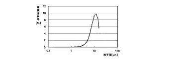
図11は、容器や自動車部品など幅広い用途に使用されている熱可塑性樹脂であるポリプロピレンを、レーザー加工機で加工したときに発生したヒュームの粒度分布を測定した図である。また、図12は、図11を基にして換算した粒子径と体積含有率の関係を表した図である。図11の試験結果より、ヒュームに含まれる粒子径の範囲としては、最小流径は約0.2μmであり、最大流径は約15μmであり、また積算値 50%の粒度である平均粒径は、 d50=0.933μ mであることが分かった。また図12の試験結果より、比較的大きな粒子である粒子径10μ m付近において、体積の占める割合が大きいことが分かった。
<Particle size distribution of dust-containing air>
FIG. 11 is a diagram showing the particle size distribution of fumes generated when polypropylene, which is a thermoplastic resin used in a wide range of applications such as containers and automobile parts, is processed with a laser processing machine. Moreover, FIG. 12 is a figure showing the relationship between the particle diameter converted based on FIG. 11, and a volume content rate. From the test results shown in FIG. 11, the range of the particle diameter contained in the fume is such that the minimum flow diameter is about 0.2 μm, the maximum flow diameter is about 15 μm, and the average particle diameter is 50% of the integrated value. Was found to be d50 = 0.933 μm. From the test results of FIG. 12, it was found that the volume occupies a large ratio in the vicinity of a particle size of 10 μm, which is a relatively large particle.
以上の試験結果から、体積占有率が大きい粒子径10μ m付近の粒子を確実に捕集するための第1エレクトレット濾過材Aを、濾過面の最も上流側に配置し、その下流側に粒子含有率が最も多い0.5〜1μ m付近の粒子を確実に捕集するための第2エレクトレット濾過材Bを配置し、更に下流に、両エレクトレット濾過材A、Bでは捕集が困難である非常に細かい0.3〜0.5μm付近の粒子を捕集するための高性能濾過材Cを配置した本発明のフィルタ10の濾過体ZKは、図11、図12の分布図より、ヒュームを捕集するのに最適な構成であることがわかる。
From the above test results, the first electret filter material A for reliably collecting particles having a large volume occupancy in the vicinity of a particle diameter of 10 μm is arranged on the most upstream side of the filtration surface, and contains particles on the downstream side thereof. The second electret filter medium B for reliably collecting particles in the vicinity of 0.5 to 1 μm, which has the highest rate, is arranged, and further downstream, both the electret filter media A and B are very difficult to collect. The filter body ZK of the
<フィルタを構成する各層の濾過材の付着量及び付着割合>
フィルタ10の積層構成の効果を確かめるために、試験片をレーザー加工した際に発生するヒュームをフィルタ10で捕集した後、フィルタ10を構成する各層の濾過材の付着量及び付着状態を調べる。
<Adhesion amount and adhesion ratio of filter material of each layer constituting filter>
In order to confirm the effect of the laminated structure of the
〔試験条件〕
レーザー加工機:炭酸ガスレーザー加工機
レーザー出力:12W
試験片:ポリプロピレン
ヒューム濃度:約85mg/m3
フィルタ素材:第1、第2、第3の各エレクトレット濾過材A、B、Cを使用
フィルタの構成:上流側(濾過面側)から各エレクトレット濾過材A,B,Cを積層
フィルタの大きさ:100mm×100mmフィルタの濾過速度:5.8 m/min
測定時間:1時間30分(フィルタ差圧が 1500Paに到達するまで測定)
〔Test conditions〕
Laser machine: Carbon dioxide laser machine Laser output: 12W
Test piece: Polypropylene fume concentration: about 85 mg / m 3
Filter material: First, second, and third electret filter media A, B, and C are used. Filter configuration: Electret filter media A, B, and C are stacked from the upstream side (filter surface side). : Filtration speed of 100 mm x 100 mm filter: 5.8 m / min
Measurement time: 1 hour 30 minutes (measured until the filter differential pressure reaches 1500 Pa)
〔実験結果〕
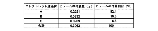
各々の濾過材に対してのヒュームの付着量及び付着割合をまとめた表を、図19に示す。
〔Experimental result〕
FIG. 19 shows a table summarizing the amount and amount of fume deposited on each filter medium.
〔考察〕
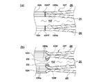
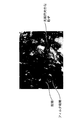
上記の結果より、ヒュームの付着割合が上流側(濾過面側)である第1エレクトレット濾過材Aから第2エレクトレット濾過材B、第3のエレクトレット濾過材Cと減少していて、密度が低い濾過材Aで最も多くヒュームを捕集し、密度が高くなる第2、第3の各エレクトレット濾過材B,Cに向かうに従いヒュームの付着量が減っていく理想的な捕集状態となっていることが実験により確認できた。また、各々のエレクトレット濾過材A,B,Cの捕集状態を光学式顕微鏡を用いて観察したものが図13(第1エレクトレット濾過材A)、図14(第2エレクトレット濾過材B)、図15(第3エレクトレット濾過材C)である。図13では、フィルタ繊維によって比較的大きな粒子が捕集されていて、また、フィルタ繊維間には、十分な通気性が確保されており、目詰まりしていない状態が確認できた。
[Discussion]
From the above results, the fume adhesion rate is decreased from the first electret filter medium A on the upstream side (filter surface side) to the second electret filter medium B and the third electret filter medium C, and the density is low. It is in an ideal collection state in which the amount of fume adhering decreases as it goes to each of the second and third electret filter media B and C, where the material A collects the most fume and the density increases. It was confirmed by experiment. Moreover, what observed the collection state of each electret filter material A, B, C using the optical microscope is FIG. 13 (1st electret filter material A), FIG. 14 (2nd electret filter material B), FIG. 15 (third electret filter medium C). In FIG. 13, relatively large particles were collected by the filter fibers, and sufficient air permeability was ensured between the filter fibers, and it was confirmed that the filter fibers were not clogged.
図14では、一部第1エレクトレット濾過材Aで捕集できなかった比較的大きな粒子などがフィルタ10の繊維によって捕集されているが、フィルタ10の繊維間には、通気性が確保されており、目詰まりしていない状態が確認できた。また、図15では、第1、第2のエレクトレット濾過材A,Bでは捕集困難であった非常に細かい粒子が第3のエレクトレット濾過材Cで捕集されていて、フィルタ繊維間には、十分な通気性が確保されており、目詰まりしていない状態が確認できた。
In FIG. 14, relatively large particles that could not be collected by the first electret filter material A are collected by the fibers of the
<風量制御について>
通常、含塵空気中のヒュームを集塵装置50にて集塵する場合、ヒュームの発生量は、工程ごとにある程度決まっているのが一般的であり、以下にヒュームの含塵量(含塵濃度)に応じた風量制御について詳細に述べる。実施例では、集塵装置50内のフィルタ10より上流側である吸込口53Hに、含塵空気中の粉塵濃度を測定する粉塵濃度測定手段である粉塵濃度計61を取付けてある。また集塵装置50内のフィルタ10の下流側であるブロワモータ57の吸引口に接続してある接続管58内には、濾過風量を測定するための風量センサ62を取付けてある。
<About air volume control>
Normally, when collecting dust in the dust-containing air with the
次に、本発明の作用を図16のフローチャートに従って説明する。先ず、ステップ1にて集塵装置50の運転スイッチ(図示省略)のON動作により運転が開始されると、ステップS2に進んで集塵装置50の吸引源であるブロワモータ57が回転を開始し、吸込口53Hより含塵空気の吸引を開始すると同時に、ステップS3で粉塵濃度計61及び風量センサ62も測定を開始する。
Next, the operation of the present invention will be described with reference to the flowchart of FIG. First, when the operation is started by turning on the operation switch (not shown) of the
運転時間の経過に伴い、ステップS4に進んで制御部からの指令により、ブロワモータ57の回転数は次第に上がっていく。次いで、風量センサ62及び粉塵濃度計61は、一定時間間隔で測定を行い、その測定値を制御部に出力する。その結果、ブロワモータ57の回転数の上昇に伴い、風量センサ62及び粉塵濃度計61からの出力値より算出される風量と単位風量あたりの粉塵濃度の関係は、図17のように運転開始時には風量−単位風量あたりの粉塵濃度曲線が急勾配で上昇するが、粉塵発生量がある程度一定量であるため、風量が上昇するに従い、風量の増加分に比べて単位風量あたりの粉塵濃度の増加分が少ないので、次第に風量−単位風量あたりの粉塵濃度曲線の勾配が緩やかになっていき、最終的には、ステップS5で風量が増加しても単位風量あたりの粉塵濃度が増加しない、粉塵濃度飽和点(以下飽和点Aと称す)に達することとなる。
As the operation time elapses, the process proceeds to step S4, and the rotational speed of the
風量−単位風量あたりの粉塵濃度曲線は、飽和点A以降、風量をあげても粉塵濃度は上がらないので、飽和点Aを維持するようにブロワモータ57の回転数を制御することが最も集塵効率が良いということになる。更に、フィルタ10の濾過性能以上に負荷を掛けることもなく、その結果、早期にフィルタ10の目詰まりが発生することも防止する。
Since the dust concentration curve per unit air volume does not increase even if the air volume is increased after the saturation point A, controlling the rotation speed of the
具体的に飽和点Aの算出の方法としては、図18において符号100で全体的に示した制御部において、一定時間間隔(例えば数秒程度の間隔)で風量センサ62からの風量、及び粉塵濃度計61からの粉塵濃度をサンプリングし、単位風量あたりの粉塵濃度を算出する。風量が増加しているにも関わらず、ステップS6で単位風量あたりの粉塵濃度が一定となるまでブロワモータ57の回転数を上げる。その後、更にブロワモータ57の回転数を上昇させても、単位風量あたりの粉塵濃度に変化がなければ、単位風量あたりの粉塵濃度が飽和したと判断し、その後は、ブロワモータ57の回転数を単位風量あたりの粉塵濃度に変化がない飽和点Aまで落として、ステップS8でその回転数を維持しながら運転を継続した後、ステップS9、S10に進んで処理を終えることとなる。
Specifically, as a method of calculating the saturation point A, in the control unit generally indicated by
飽和点Aを検出後には、粉塵濃度計61の汚れを考慮して取り外しても構わない。また作業が変更するなどして発生する粉塵濃度が異なる場合においては、再度、粉塵濃度計61により粉塵濃度を測定して飽和点Aを検出して、最適な風量で運転を行えば良い。
After detecting the saturation point A, the
なお図18には、本発明の構成を示すブロック図を示し、制御部100を構成するCPU101及びメモリ102はインターフェース104及びバス103を介して、設定部60からの運転設定条件に基づき運転を行い、粉塵濃度計61及び風量センサ62からの信号により風量一定となるようにブロワモータ57の回転数を可変制御する。また、粉塵濃度計61は始業点検時のみ接続する方法でも構わない。このような方法にすることで、複数の集塵装置50…に対して、1台の粉塵濃度計61で測定することができて、コストアップを防ぐことができる。而して図18において、105と106は前記操作パネル60に設けられた表示器と設定入力部である。
FIG. 18 is a block diagram showing the configuration of the present invention. The
ZK フィルタ濾過体
A 第1エレクトレット濾過材
B 第2エレクトレット濾過材
C 第3エレクトレット濾過材
D 高性能濾過材
10 集塵用フィルタ
10T フィルタ単体
10K 紐体
10S 外端部
10X 通気性部材
10H 通気穴
10HT かがり縫い
20 密着防止板
20X 長辺状の櫛片
50 集塵装置
ZK filter filter body A 1st electret filter medium B 2nd electret filter medium C 3rd electret filter medium D High performance filter medium 10 Filter for
Claims (9)
上記集塵用フィルタより上流側には、含塵空気中の含塵濃度を測定することができる粉塵濃度測定手段を設けて、
上記の制御部は、風量値と粉塵濃度値より単位風量当りの粉塵濃度値、即ち、粉塵濃度を風量で割った値を演算し、
風量を上昇させても単位風量当りの粉塵濃度値が変化しない値を粉塵濃度飽和値として、この粉塵濃度飽和値を維持しつつ、上記風量検出手段から算出される風量値が最小となるように上記ブロワモータの回転数を制御することを特徴とする請求項5、6、7及び8に記載の集塵装置。 The air volume measuring means capable of measuring the filtered air volume, the blower motor capable of changing the rotational speed, and the rotation of the blower motor based on the signal from the air volume measuring means inside the dust collector and downstream of the dust collecting filter. And a control unit for variably controlling the number,
On the upstream side of the dust collecting filter, a dust concentration measuring means capable of measuring the dust concentration in the dust-containing air is provided,
The above control unit calculates the dust concentration value per unit air volume from the air volume value and the dust density value, that is, a value obtained by dividing the dust density by the air volume,
The value that the dust concentration value per unit air volume does not change even if the air volume is increased is taken as the dust concentration saturation value, and the air volume value calculated from the air volume detection means is minimized while maintaining this dust concentration saturation value. The dust collector according to claim 5, 6, 7, or 8, wherein the rotational speed of the blower motor is controlled.
Priority Applications (1)
| Application Number | Priority Date | Filing Date | Title |
|---|---|---|---|
| JP2011036143A JP2012170904A (en) | 2011-02-22 | 2011-02-22 | Dust-collecting filter and dust-collecting apparatus having the same filter |
Applications Claiming Priority (1)
| Application Number | Priority Date | Filing Date | Title |
|---|---|---|---|
| JP2011036143A JP2012170904A (en) | 2011-02-22 | 2011-02-22 | Dust-collecting filter and dust-collecting apparatus having the same filter |
Related Child Applications (1)
| Application Number | Title | Priority Date | Filing Date |
|---|---|---|---|
| JP2015184753A Division JP6117882B2 (en) | 2015-09-18 | 2015-09-18 | Dust collection filter and dust collector equipped with the filter |
Publications (1)
| Publication Number | Publication Date |
|---|---|
| JP2012170904A true JP2012170904A (en) | 2012-09-10 |
Family
ID=46974313
Family Applications (1)
| Application Number | Title | Priority Date | Filing Date |
|---|---|---|---|
| JP2011036143A Pending JP2012170904A (en) | 2011-02-22 | 2011-02-22 | Dust-collecting filter and dust-collecting apparatus having the same filter |
Country Status (1)
| Country | Link |
|---|---|
| JP (1) | JP2012170904A (en) |
Cited By (2)
| Publication number | Priority date | Publication date | Assignee | Title |
|---|---|---|---|---|
| JP2022023302A (en) * | 2020-07-27 | 2022-02-08 | 三菱電機株式会社 | Humidification component and humidification device |
| CN116475517A (en) * | 2023-06-21 | 2023-07-25 | 西安感崆电子信息科技有限公司 | Tool fixture for soldering circuit board components |
Citations (10)
| Publication number | Priority date | Publication date | Assignee | Title |
|---|---|---|---|---|
| JPS5778917A (en) * | 1980-11-04 | 1982-05-17 | Kanai Hiroyuki | Electrostatic induction type filter medium |
| JPH08117527A (en) * | 1994-10-21 | 1996-05-14 | Nippon Muki Co Ltd | Air filter |
| JPH11507868A (en) * | 1995-06-16 | 1999-07-13 | イーストマン ケミカル カンパニー | Composite fiber filter |
| JP2004243250A (en) * | 2003-02-14 | 2004-09-02 | Dynic Corp | Air filter material |
| JP2004529753A (en) * | 2000-11-14 | 2004-09-30 | リダル、インコーポレイテッド | Airlaid / wet laid gas filtration media |
| JP2005147034A (en) * | 2003-11-18 | 2005-06-09 | Mitsubishi Heavy Ind Ltd | Air filter for gas turbine, and washing method and washing system for the same, and service life prediction testing method for the same |
| WO2005107920A1 (en) * | 2004-05-12 | 2005-11-17 | Ambic Co., Ltd. | Material for air filter |
| JP2007014891A (en) * | 2005-07-08 | 2007-01-25 | Amano Corp | Filter for dust collector |
| JP2009226321A (en) * | 2008-03-24 | 2009-10-08 | Toray Ind Inc | Flame-retardant electret filter medium and filter unit |
| JP2010104905A (en) * | 2008-10-30 | 2010-05-13 | Kurashiki Seni Kako Kk | Laminated nonwoven fabric for air filter, method for manufacturing the same, and air filter |
-
2011
- 2011-02-22 JP JP2011036143A patent/JP2012170904A/en active Pending
Patent Citations (10)
| Publication number | Priority date | Publication date | Assignee | Title |
|---|---|---|---|---|
| JPS5778917A (en) * | 1980-11-04 | 1982-05-17 | Kanai Hiroyuki | Electrostatic induction type filter medium |
| JPH08117527A (en) * | 1994-10-21 | 1996-05-14 | Nippon Muki Co Ltd | Air filter |
| JPH11507868A (en) * | 1995-06-16 | 1999-07-13 | イーストマン ケミカル カンパニー | Composite fiber filter |
| JP2004529753A (en) * | 2000-11-14 | 2004-09-30 | リダル、インコーポレイテッド | Airlaid / wet laid gas filtration media |
| JP2004243250A (en) * | 2003-02-14 | 2004-09-02 | Dynic Corp | Air filter material |
| JP2005147034A (en) * | 2003-11-18 | 2005-06-09 | Mitsubishi Heavy Ind Ltd | Air filter for gas turbine, and washing method and washing system for the same, and service life prediction testing method for the same |
| WO2005107920A1 (en) * | 2004-05-12 | 2005-11-17 | Ambic Co., Ltd. | Material for air filter |
| JP2007014891A (en) * | 2005-07-08 | 2007-01-25 | Amano Corp | Filter for dust collector |
| JP2009226321A (en) * | 2008-03-24 | 2009-10-08 | Toray Ind Inc | Flame-retardant electret filter medium and filter unit |
| JP2010104905A (en) * | 2008-10-30 | 2010-05-13 | Kurashiki Seni Kako Kk | Laminated nonwoven fabric for air filter, method for manufacturing the same, and air filter |
Cited By (4)
| Publication number | Priority date | Publication date | Assignee | Title |
|---|---|---|---|---|
| JP2022023302A (en) * | 2020-07-27 | 2022-02-08 | 三菱電機株式会社 | Humidification component and humidification device |
| JP7262429B2 (en) | 2020-07-27 | 2023-04-21 | 三菱電機株式会社 | Humidification parts and humidifiers |
| CN116475517A (en) * | 2023-06-21 | 2023-07-25 | 西安感崆电子信息科技有限公司 | Tool fixture for soldering circuit board components |
| CN116475517B (en) * | 2023-06-21 | 2023-11-28 | 德庆县瑞晶电子材料有限公司 | Tool fixture for soldering circuit board components |
Similar Documents
| Publication | Publication Date | Title |
|---|---|---|
| JP6595566B2 (en) | Air filtering device | |
| KR102254682B1 (en) | Methods of filtering air | |
| KR101858329B1 (en) | Collapsible air filtering device | |
| CA2909872C (en) | Air filtering device | |
| KR101950082B1 (en) | Air filter bag | |
| JP2016093805A (en) | Filter media construction for hepa efficiency and odor control | |
| CN103785231B (en) | A kind of air filter | |
| US9174162B2 (en) | Machine tool mounted mist collector with filter clamp | |
| JP2008159281A (en) | Gas removal filtering device of fuel cell | |
| JP6117882B2 (en) | Dust collection filter and dust collector equipped with the filter | |
| JP2012170904A (en) | Dust-collecting filter and dust-collecting apparatus having the same filter | |
| JP2012026692A (en) | Air cleaner | |
| US8758487B2 (en) | Machine tool mounted mist collector | |
| JP2006057900A (en) | Air cleaning filter and air treatment device provided therewith | |
| US20140053722A1 (en) | Machine tool mounted mist collector with automatic control | |
| US20110308208A1 (en) | Pre-Filter Particulate Collection Member | |
| JP2018138069A (en) | Filter medium and air cleaner using the same | |
| JP2012152754A (en) | Dust collecting filter, method for manufacturing dust collecting filter and air cleaner | |
| CN217863218U (en) | Integral type solventless laminator | |
| KR100830136B1 (en) | Manufacturing method of air cleaner filter | |
| JP2004000926A (en) | Filter medium for air filter, air filter unit, its production method and packaged body of the same | |
| JPH10272316A (en) | Sock filter | |
| JP2002327941A (en) | Air cleaner | |
| JPH0584421A (en) | Air cleaner | |
| JP2004188133A (en) | Dust removing filter for air inlet of medical oxygen condenser |
Legal Events
| Date | Code | Title | Description |
|---|---|---|---|
| A621 | Written request for application examination |
Free format text: JAPANESE INTERMEDIATE CODE: A621 Effective date: 20131115 |
|
| A977 | Report on retrieval |
Free format text: JAPANESE INTERMEDIATE CODE: A971007 Effective date: 20140521 |
|
| A131 | Notification of reasons for refusal |
Free format text: JAPANESE INTERMEDIATE CODE: A131 Effective date: 20140527 |
|
| A521 | Written amendment |
Free format text: JAPANESE INTERMEDIATE CODE: A523 Effective date: 20140725 |
|
| A131 | Notification of reasons for refusal |
Free format text: JAPANESE INTERMEDIATE CODE: A131 Effective date: 20150303 |
|
| A02 | Decision of refusal |
Free format text: JAPANESE INTERMEDIATE CODE: A02 Effective date: 20150625 |