JP2012169447A - Photovoltaic power generation system - Google Patents
Photovoltaic power generation system Download PDFInfo
- Publication number
- JP2012169447A JP2012169447A JP2011028990A JP2011028990A JP2012169447A JP 2012169447 A JP2012169447 A JP 2012169447A JP 2011028990 A JP2011028990 A JP 2011028990A JP 2011028990 A JP2011028990 A JP 2011028990A JP 2012169447 A JP2012169447 A JP 2012169447A
- Authority
- JP
- Japan
- Prior art keywords
- solar cell
- state
- solar
- output voltage
- output
- Prior art date
- Legal status (The legal status is an assumption and is not a legal conclusion. Google has not performed a legal analysis and makes no representation as to the accuracy of the status listed.)
- Pending
Links
Images

Classifications
-
- Y—GENERAL TAGGING OF NEW TECHNOLOGICAL DEVELOPMENTS; GENERAL TAGGING OF CROSS-SECTIONAL TECHNOLOGIES SPANNING OVER SEVERAL SECTIONS OF THE IPC; TECHNICAL SUBJECTS COVERED BY FORMER USPC CROSS-REFERENCE ART COLLECTIONS [XRACs] AND DIGESTS
- Y02—TECHNOLOGIES OR APPLICATIONS FOR MITIGATION OR ADAPTATION AGAINST CLIMATE CHANGE
- Y02E—REDUCTION OF GREENHOUSE GAS [GHG] EMISSIONS, RELATED TO ENERGY GENERATION, TRANSMISSION OR DISTRIBUTION
- Y02E10/00—Energy generation through renewable energy sources
- Y02E10/50—Photovoltaic [PV] energy
Abstract
Description
本発明は、太陽電池の最大電力動作点を追跡制御(以下、MPPT制御)する太陽光発電システムに関するものであり、特には、太陽光発電システムにおいて太陽電池の状態を検出することに関するものである。 The present invention relates to a solar power generation system that performs tracking control (hereinafter referred to as MPPT control) of the maximum power operating point of a solar cell, and particularly relates to detecting the state of a solar cell in the solar power generation system. .
太陽エネルギーを利用した太陽光発電システムでは近年におけるその普及はめざましい。そして太陽光発電システムは、太陽光による発電電力を自家使用するのみでなく、余剰電力を商用電力として出力することにより、効率的な電力利用を図られるようになっている。こうした太陽光発電システムにおいては、太陽電池が出力する直流電力を交流電力に変換して負荷側(負荷、商用電源)に出力するパワーコンディショナを有する。パワーコンディショナには、太陽電池出力を昇圧するDC/DCコンバータと、このDC/DCコンバータ出力をDC/AC変換するDC/ACインバータとを有するものがある。 In recent years, the spread of solar power generation systems using solar energy has been remarkable. And the solar power generation system can be used efficiently by not only using the power generated by the solar power but also outputting surplus power as commercial power. Such a solar power generation system has a power conditioner that converts DC power output from the solar cell into AC power and outputs the AC power to the load side (load, commercial power supply). Some power conditioners have a DC / DC converter that boosts the solar cell output and a DC / AC inverter that DC / AC converts the DC / DC converter output.
こうした太陽光発電システムで電力変換される太陽電池は、詳細は略するが、日射量や素子温度等その周囲の環境変化に伴って出力電力が変化するために、通常、当該太陽電池が最大出力電力で動作する点を追跡制御するMPPT制御が行われている(特許文献1参照)。 Although the details of the solar cells that are converted into power by such a solar power generation system are omitted, the output power changes with the surrounding environmental changes such as the amount of solar radiation and the element temperature. MPPT control for tracking and controlling points operating with electric power is performed (see Patent Document 1).
そこで、本発明は、上記太陽光発電システムにおいて太陽電池の状態を検出し、その検出の結果に応じて、例えば故障情報、交換時期情報を得たりして、所要の措置を例えば早期に講じることができるようにすることを解決すべき課題としている。 Therefore, the present invention detects the state of the solar cell in the solar power generation system, and obtains, for example, failure information and replacement time information according to the detection result, and takes necessary measures, for example, at an early stage. It is a problem to be solved to make it possible.
本発明による太陽光発電システムは、太陽電池と、パワーコンディショナと、を含み、上記パワーコンディショナは、上記太陽電池の出力電圧と出力電力の状態に基づいてMPPT制御を行うものである太陽光発電システムであって、当該システムは、太陽電池の状態を検出する装置を具備し、上記装置は、太陽電池の出力電圧と出力電流とを変化させ、この変化の状態から太陽電池の状態を検出する、ことを特徴とする。 A solar power generation system according to the present invention includes a solar cell and a power conditioner, and the power conditioner performs MPPT control based on the state of the output voltage and output power of the solar cell. A power generation system comprising a device for detecting the state of a solar cell, the device changing the output voltage and output current of the solar cell, and detecting the state of the solar cell from the state of change It is characterized by.
上記装置は、好ましくは、日射量や太陽電池の素子温度のデータも含めて太陽電池の状態を検出する。 The apparatus preferably detects the state of the solar cell including data on the amount of solar radiation and the element temperature of the solar cell.
上記装置は、好ましくは、太陽電池の状態検出結果を太陽光発電システムにおけるリモコン装置やサーバ、その他と通信する機能を備える。 Preferably, the device has a function of communicating the state detection result of the solar cell with a remote control device, a server, or the like in the solar power generation system.
上記装置は、好ましくは、所定期間ごとに太陽電池の出力電圧、出力電流、日射量、温度等のデータを記憶し、その記憶内容に基づいて太陽電池の状態の統計的処理を行い、その結果から太陽電池の状態を検出する。 The device preferably stores data such as output voltage, output current, solar radiation, temperature, etc. of the solar cell every predetermined period, and performs statistical processing of the state of the solar cell based on the stored contents, and results thereof. To detect the state of the solar cell.
本発明では、太陽電池の状態を検出し、その検出の結果に応じて例えば故障情報、交換時期の情報などを取得して所要の措置を例えば早期に講じたりするようにことができるようになる。 In the present invention, it is possible to detect the state of the solar cell and acquire, for example, failure information, replacement time information, etc. according to the detection result and take necessary measures, for example, at an early stage. .
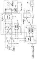
以下、添付した図面を参照して、本発明の実施の形態に係る太陽光発電システムを説明する。図1に本発明の実施形態に係る太陽光発電システムの構成を示す。図1において、符号1は、太陽電池、3はパワーコンディショナ、5は負荷側(負荷5a、商用電源5bを含む)である。太陽電池1はその状態が検出されるべきものであり、太陽電池セルを複数枚直並列接続して必要な電圧と電流を得られるようにしたパネル状に限定されず、モジュール状、アレイ状等のいずれも含む。この太陽電池1にはシリコン系、化合物系、有機系等の太陽電池を含むことができる。太陽電池1はその水分の浸入、紫外線の照射など様々な要因で劣化してくるようになる。実施形態ではこの太陽電池1の状態を検出するようにしている。
Hereinafter, a solar power generation system according to an embodiment of the present invention will be described with reference to the accompanying drawings. FIG. 1 shows a configuration of a photovoltaic power generation system according to an embodiment of the present invention. In FIG. 1, reference numeral 1 is a solar cell, 3 is a power conditioner, and 5 is a load side (including a load 5a and a
パワーコンディショナ3は、太陽電池1の出力電圧を昇圧する昇圧型DC/DCコンバータ7と、DC/DCコンバータ7の直流出力をDC/AC変換するDC/ACインバータ9と、MPPT制御を行うMPPT制御部11とを含む。DC/DCコンバータ7は、コイル7a、スイッチング素子7b、ダイオード7c、およびコンデンサ7dを含む。このDC/DCコンバータ7の上記構成素子に対してMPPT制御部11により制御して太陽電池1出力を昇圧しMPPT制御する動作は周知である。このMPPT制御のため、太陽電池1とパワーコンディショナ3との間には太陽電池1の出力電圧を検出する出力電圧センサ13と、太陽電池1の出力電流を検出する出力電流センサ15とが設けられている。17は太陽電池1への日射量を検出する日射量センサ、19は太陽電池1の素子温度を検出する温度センサである。
The
MPPT制御部11は、出力電圧センサ13,出力電流センサ15からの出力を入力し、これら各センサ出力から所要の演算を行い、この演算出力からDC/DCコンバータ7内のスイッチング素子7bをオンオフしてMPPT制御を行うようになっている。
The
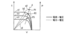
図2に、横軸に出力電圧V、左縦軸に出力電流I、右縦軸に出力電力Pをとり、出力電流−出力電圧曲線a1,b1,c1を実線で、出力電力−出力電圧曲線a2,b2,c2を破線で示す。 In FIG. 2, the horizontal axis represents the output voltage V, the left vertical axis represents the output current I, the right vertical axis represents the output power P, the output current-output voltage curves a1, b1, c1 are solid lines, and the output power-output voltage curve. a2, b2, and c2 are indicated by broken lines.
そして、曲線a1とa2とが第1日射量に対応し、曲線b1とb2とが第2日射量に対応し、曲線c1とc2とが第3日射量に対応している。なお、曲線a1、b1、c1、a2、b2、c2は温度の影響も受ける。 The curves a1 and a2 correspond to the first solar radiation amount, the curves b1 and b2 correspond to the second solar radiation amount, and the curves c1 and c2 correspond to the third solar radiation amount. The curves a1, b1, c1, a2, b2, and c2 are also affected by temperature.
線d上で出力電力−出力電圧曲線a2,b2,c2のピーク点P1,P2,P3は太陽電池1が最大出力電力に制御(MPPT制御)されている点である。 Peak points P1, P2, and P3 of the output power-output voltage curves a2, b2, and c2 on the line d are points where the solar cell 1 is controlled to the maximum output power (MPPT control).
MPPT制御部11は上記MPPT制御が行われるようDC/DCコンバータ7のスイッチング素子7bのオンオフを制御する。
The
以上の構成において本実施形態では以下で説明するように太陽電池1の状態を検出する太陽電池状態検出装置21を設けている。
In the above configuration, the solar cell
この太陽電池状態検出装置21は既設の太陽光発電システムにオプションで付設してもよいし、当初から太陽光発電システムに組み込むようにしてもよい。
This solar cell
太陽電池状態検出装置21は、動作制御部23、記憶部25、および通信部27、を備える。29はリモコン装置、40はサーバを示す。
The solar cell
太陽電池状態検出装置21において、動作制御部23は、太陽電池1の状態検出に際してMPPT制御部11に対してMPPT制御の動作を停止させると共にDC/DCコンバータ7のスイッチング素子7bのオンオフを制御して太陽電池1の出力電圧と出力電流とを変化させ、この変化の状態を出力電圧センサ13、出力電流センサ15、日射量センサ17、温度センサ19とから得ると共に、そのセンサ出力に基づいて太陽電池1の状態を検出する。動作制御部23は、構成的には、MPPT制御部11とは別のCPUで構成してもよいし、同一のCPUで構成してもよい。動作制御部23は図面的には単一ブロックで示すが、機能的には複数の機能を有するため、複数の機能ブロックで表すこともできるが、実施形態では説明の都合で、動作制御部23を複数の機能ブロックであらわしていない。動作制御部23はCPUと適宜の記憶部とを有し、記憶部には太陽電池1の状態検出のための制御プログラムがインストールされており、CPUはこの制御プログラムに従い太陽電池1の状態検出のために必要な制御動作を実行する。
In the solar cell
記憶部25は、太陽電池1の状態検出に必要とする出力電圧、出力電流、日射量、温度のデータを記憶する。動作制御部23は、記憶部25に対して太陽電池1の状態検出に必要とする出力電圧、出力電流、日射量、温度の記憶動作を制御すると共に、所定の制御プログラムに従い、この記憶内容から太陽電池1の状態の検出を行う。動作制御部23は、上記出力電圧センサ13と出力電流センサ15、日射量センサ17、温度センサ19それぞれのセンサ出力を記憶部25に記憶させる制御を行うが、この場合、その記憶させる時点での日射量センサ17,温度19の検出データも同時に対応付けして記憶させる。さらには、動作制御部23は、日時、日射量、温度、電圧、電流、さらには電圧と電流とから電力を計算しその計算した電力を記憶部25に記憶させる。
The
この実施形態では、太陽電池1の劣化状況を負荷5に電力を供給しながら調べその交換を促す情報を各太陽電池1で調べられるようにする。
In this embodiment, the deterioration state of the solar cell 1 is checked while supplying electric power to the
動作制御部23は太陽電池1の検出時には、基準の出力電流、出力電圧、日射量、温度のデータを記憶部25から読み込むと共に、その読み込んだ出力電流−出力電圧変化と、検出した出力電流−出力電圧変化とを比較し、太陽電池1の劣化状態を判定することができるようになっている。この場合、太陽電池1の劣化状態は、パーセント表示してもよい。例えば、太陽電池1の初期状態における出力電流−出力電圧変化の関係を100%とし、検出時点での出力電流−出力電圧変化の関係が例えば80%であれば、例えば劣化度20%と判定できるようにしてもよい。
When detecting the solar cell 1, the
通信部27は、動作制御部23による太陽電池1の状態判定結果をリモコン装置29やサーバ40に通信する。動作制御部23は、通信部27における上記通信動作を制御する。リモコン装置29側から太陽電池1の状態検出開始信号が送信され、通信部27がこの状態検出開始信号を受信すると、太陽電池状態検出装置21では、太陽電池1の状態検出動作を開始する。また、通信部27から太陽電池1の状態検出信号が送信され、リモコン装置29でその状態検出信号を受信すると、リモコン装置29ではその受信の内容を表示する。
The
リモコン装置29では、各種の表示を行うモニタ31と、各種操作を行うと共に太陽電池1の状態の判定結果を得るための操作も行うことができる操作部33と、太陽電池状態検出装置21の通信部27から送信される判定データを表示する表示部35,37とを具備する。リモコン装置29から操作部33の操作データが太陽電池状態検出装置21の通信部27に送信されると、太陽電池状態検出装置21はその送信に応答して、太陽電池1の状態データを通信部27を介してリモコン装置29に送信する。リモコン装置29ではその送信信号が太陽電池1の状態の判定信号であり、その判定信号が太陽電池1の状態が良好であるとする信号であれば表示部35を青色に発光表示させ、そうでなく劣化などして不良であるとする信号であれば表示部37を赤色に発光表示させ、これによりリモコン装置29のユーザに太陽電池1の状態を知らせることができるようになっている。また、リモコン装置29からサーバ40に通信すれば太陽電池1の劣化状態をサーバ40により一括管理ができ、太陽電池1等のメンテナンス情報を早めに出すことができたりする。
In the
図3に本発明の他の実施形態にかかる太陽光発電システムを示す。この実施形態では、日射量センサ17、温度センサ19を使用していない。この実施形態において、動作制御部23には、太陽電池状態検出用ソフトがダウンロードされ、このソフトに規定されるフローチャートに従い、所定期間、例えば毎日、毎週、毎月、あるいは季節ごとに、MPPT制御部11の動作を停止させると共に、DC/DCコンバータ7のスイッチング素子7bをオンオフして、太陽電池1の出力電流0のところから出力電圧0のところまで出力電流と出力電圧とを変化させ、その出力電流−出力電圧変化特性、あるいは出力電力−出力電圧変化特性を記憶部25に記憶させる。そして、この記憶部25における記憶内容に基づいて、太陽電池1の状態の統計的処理を行い、その結果から太陽電池1の状態を判定することができるようにしている。
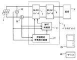
FIG. 3 shows a photovoltaic power generation system according to another embodiment of the present invention. In this embodiment, the
図4に本発明のさらに他の実施形態にかかる太陽光発電システムを示す。この実施形態では、日射量センサ17、温度センサ19が使用されていない状態で示すが、これらセンサ17,19を使用してもよい。この実施形態では、太陽電池状態検出装置21はパワーコンディショナ3に内蔵されている。この実施形態において、動作制御部23の動作は日射量センサ17、温度センサ19を使用しているときは図1の太陽光発電システムと同様であり、日射量センサ17、温度センサ19を使用していないときは図3の太陽光発電システムと同様である。
FIG. 4 shows a photovoltaic power generation system according to still another embodiment of the present invention. In this embodiment, the solar
なお、太陽電池状態検出装置21による太陽電池1の状態判定結果は、リモコン装置29のモニタ画面31上に表示させてもよいし、適宜のモニタ画面に表示できるようにしてもよい。
In addition, the state determination result of the solar cell 1 by the solar cell
なお、パワーコンディショナ3においては、太陽電池1の最大出力点の電圧が高く、昇圧する必要がない場合は、昇圧回路7を用いず、DC/ACインバータ9だけで構成することができる。このようなパワーコンディショナとした場合、発電しながら太陽電池1の特性の劣化状態を調べようとするに際しては、太陽電池1の電流0からDC/ACインバータ9のDC電圧として必要な最低電圧(おおよそ系統電圧の振幅値)まででしか太陽電池1の特性を調べることができないが、その場合でも太陽電池1の特性の劣化を検出することができる。
In the
以上説明したように本実施形態では、太陽電池の太陽電池状態検出装置21を具備し、この太陽電池状態検出装置21により、太陽電池1の状態検出に際しては、太陽電池1の出力電圧と出力電流とを変化させ、この変化の状態から太陽電池1の状態を検出するようにしたから、その検出結果に応じて、例えば故障情報、交換時期情報を得て、所要の措置を例えば早期に講じることができるようになる。
As described above, in the present embodiment, the solar cell
1 太陽電池
3 パワーコンディショナ
7 昇圧型DC/DCコンバータ
9 DC/ACインバータ
11 MPPT制御部
5 負荷側
13 出力電圧センサ
15 出力電流センサ
17 日射量センサ
19 温度センサ
21 太陽電池状態検出装置
23 動作制御部
25 記憶部
27 通信部
29 リモコン装置
DESCRIPTION OF SYMBOLS 1
Claims (4)
当該システムは、太陽電池の状態を検出する装置を具備し、
上記装置は、少なくとも太陽電池の出力電圧と出力電流とを変化させ、この変化の状態から太陽電池の状態を検出することを特徴とする太陽光発電システム。 A solar cell and a power conditioner, wherein the power conditioner is a solar power generation system that performs MPPT control based on the output voltage and output power state of the solar cell,
The system comprises a device for detecting the state of a solar cell,
The said apparatus changes the output voltage and output current of a solar cell at least, and detects the state of a solar cell from the state of this change, The solar power generation system characterized by the above-mentioned.
Priority Applications (1)
| Application Number | Priority Date | Filing Date | Title |
|---|---|---|---|
| JP2011028990A JP2012169447A (en) | 2011-02-14 | 2011-02-14 | Photovoltaic power generation system |
Applications Claiming Priority (1)
| Application Number | Priority Date | Filing Date | Title |
|---|---|---|---|
| JP2011028990A JP2012169447A (en) | 2011-02-14 | 2011-02-14 | Photovoltaic power generation system |
Publications (1)
| Publication Number | Publication Date |
|---|---|
| JP2012169447A true JP2012169447A (en) | 2012-09-06 |
Family
ID=46973328
Family Applications (1)
| Application Number | Title | Priority Date | Filing Date |
|---|---|---|---|
| JP2011028990A Pending JP2012169447A (en) | 2011-02-14 | 2011-02-14 | Photovoltaic power generation system |
Country Status (1)
| Country | Link |
|---|---|
| JP (1) | JP2012169447A (en) |
Cited By (11)
| Publication number | Priority date | Publication date | Assignee | Title |
|---|---|---|---|---|
| CN102880224A (en) * | 2012-10-26 | 2013-01-16 | 天津理工大学 | Double-mode maximum power point tracking (MPPT) method based on improved step length |
| JP2013101498A (en) * | 2011-11-08 | 2013-05-23 | Panasonic Corp | Power conditioner for photovoltaic power generation |
| CN103294103A (en) * | 2012-12-06 | 2013-09-11 | 许昌学院电气信息工程学院 | Solar controlled change time faze control method based on temperature detection |
| CN104020813A (en) * | 2014-05-13 | 2014-09-03 | 安徽省安泰科技股份有限公司 | MPPT hysteresis control algorithm based on FIR filter prediction |
| WO2014141498A1 (en) * | 2013-03-14 | 2014-09-18 | オムロン株式会社 | Solar power system, anomaly determination processing device, anomaly determination processing method, and program |
| JPWO2013042384A1 (en) * | 2011-09-20 | 2015-03-26 | 三菱電機株式会社 | Photovoltaic power generation system, solar power generation system diagnosis apparatus, solar power generation system diagnosis method, and program |
| JP2015133773A (en) * | 2014-01-09 | 2015-07-23 | シオン電機株式会社 | power delivery system |
| KR20150098317A (en) * | 2014-02-20 | 2015-08-28 | 오보석 | The photovoltaic power generation system |
| CN106323357A (en) * | 2015-06-17 | 2017-01-11 | 山东耀通节能环保科技股份有限公司 | Environmental monitoring system of solar power generation |
| JP2019040434A (en) * | 2017-08-25 | 2019-03-14 | オムロン株式会社 | Power conditioner having solar cell i-v curve measuring function |
| JP2019054587A (en) * | 2017-09-13 | 2019-04-04 | 東芝三菱電機産業システム株式会社 | Power conditioner system and solar power generation system |
Citations (4)
| Publication number | Priority date | Publication date | Assignee | Title |
|---|---|---|---|---|
| JP2006201827A (en) * | 2005-01-18 | 2006-08-03 | Omron Corp | Power conditioner incorporating curve tracer and curve evaluation method of curve tracer |
| JP2008046751A (en) * | 2006-08-11 | 2008-02-28 | Toyota Motor Corp | Photovoltaic power generation system, vehicle, control method for photovoltaic power generation system, and computer readable recording medium with program for making computer perform its control method reocrded |
| JP2008300745A (en) * | 2007-06-01 | 2008-12-11 | Nippon Oil Corp | Power conditioner for photovoltaic generation, photovoltaic generation system, and output power control method of photovoltaic generation system |
| JP2010287608A (en) * | 2009-06-09 | 2010-12-24 | Kowa Denki Sangyo Kk | Apparatus, system and method for detecting degradation of photovoltaic power generator |
-
2011
- 2011-02-14 JP JP2011028990A patent/JP2012169447A/en active Pending
Patent Citations (4)
| Publication number | Priority date | Publication date | Assignee | Title |
|---|---|---|---|---|
| JP2006201827A (en) * | 2005-01-18 | 2006-08-03 | Omron Corp | Power conditioner incorporating curve tracer and curve evaluation method of curve tracer |
| JP2008046751A (en) * | 2006-08-11 | 2008-02-28 | Toyota Motor Corp | Photovoltaic power generation system, vehicle, control method for photovoltaic power generation system, and computer readable recording medium with program for making computer perform its control method reocrded |
| JP2008300745A (en) * | 2007-06-01 | 2008-12-11 | Nippon Oil Corp | Power conditioner for photovoltaic generation, photovoltaic generation system, and output power control method of photovoltaic generation system |
| JP2010287608A (en) * | 2009-06-09 | 2010-12-24 | Kowa Denki Sangyo Kk | Apparatus, system and method for detecting degradation of photovoltaic power generator |
Cited By (13)
| Publication number | Priority date | Publication date | Assignee | Title |
|---|---|---|---|---|
| JPWO2013042384A1 (en) * | 2011-09-20 | 2015-03-26 | 三菱電機株式会社 | Photovoltaic power generation system, solar power generation system diagnosis apparatus, solar power generation system diagnosis method, and program |
| JP2013101498A (en) * | 2011-11-08 | 2013-05-23 | Panasonic Corp | Power conditioner for photovoltaic power generation |
| CN102880224A (en) * | 2012-10-26 | 2013-01-16 | 天津理工大学 | Double-mode maximum power point tracking (MPPT) method based on improved step length |
| CN103294103A (en) * | 2012-12-06 | 2013-09-11 | 许昌学院电气信息工程学院 | Solar controlled change time faze control method based on temperature detection |
| WO2014141498A1 (en) * | 2013-03-14 | 2014-09-18 | オムロン株式会社 | Solar power system, anomaly determination processing device, anomaly determination processing method, and program |
| JP2014179464A (en) * | 2013-03-14 | 2014-09-25 | Omron Corp | Photovoltaic power generation system, abnormality determination processor, abnormality determination processing method and program |
| JP2015133773A (en) * | 2014-01-09 | 2015-07-23 | シオン電機株式会社 | power delivery system |
| KR101581430B1 (en) * | 2014-02-20 | 2015-12-30 | 오보석 | The photovoltaic power generation system |
| KR20150098317A (en) * | 2014-02-20 | 2015-08-28 | 오보석 | The photovoltaic power generation system |
| CN104020813A (en) * | 2014-05-13 | 2014-09-03 | 安徽省安泰科技股份有限公司 | MPPT hysteresis control algorithm based on FIR filter prediction |
| CN106323357A (en) * | 2015-06-17 | 2017-01-11 | 山东耀通节能环保科技股份有限公司 | Environmental monitoring system of solar power generation |
| JP2019040434A (en) * | 2017-08-25 | 2019-03-14 | オムロン株式会社 | Power conditioner having solar cell i-v curve measuring function |
| JP2019054587A (en) * | 2017-09-13 | 2019-04-04 | 東芝三菱電機産業システム株式会社 | Power conditioner system and solar power generation system |
Similar Documents
| Publication | Publication Date | Title |
|---|---|---|
| JP2012169447A (en) | Photovoltaic power generation system | |
| US10243396B2 (en) | Control device, power control system, and power control method | |
| JP5777965B2 (en) | Fault diagnosis method, grid interconnection device, and control device | |
| JP4556677B2 (en) | Power conditioner with built-in curve tracer | |
| JP5344759B2 (en) | Power distribution system | |
| US9240705B2 (en) | Control apparatus and control method | |
| US20140042811A1 (en) | Control device, power control system, and power control method | |
| JP5648121B2 (en) | Distributed power generation system and operation method thereof | |
| KR20160001249A (en) | Home energy management system using photovoltaic generation and energy storage system | |
| JP5719714B2 (en) | Startup control method, grid interconnection device, and control device | |
| JP6029713B1 (en) | POWER MANAGEMENT DEVICE, DEVICE SYSTEM, POWER MANAGEMENT METHOD, AND PROGRAM | |
| US20110187196A1 (en) | Photovoltaic power generation systems and methods | |
| JP2012147621A (en) | Blackout relief system | |
| JP2012112632A (en) | Water heater remote controller, and water heater with the same | |
| JP5507100B2 (en) | Storage battery failure diagnosis device | |
| JP6171672B2 (en) | Power generation system and power conditioner | |
| KR20170118393A (en) | Monitoring apparatus for solar power generation system using mppt | |
| US10523015B2 (en) | Power generation apparatus, power generation system, and power generation method | |
| JP2013223316A (en) | Power control system | |
| JP2014217177A (en) | Power supply system and power storage device | |
| JP6114279B2 (en) | Energy management device and control method of energy management device | |
| US11394218B2 (en) | Controller, electricity storage system, and recording medium | |
| WO2012046381A1 (en) | Power generation system and method for operating power generation system | |
| JP6299514B2 (en) | Power supply system | |
| JP2016201931A (en) | Power Conditioner |
Legal Events
| Date | Code | Title | Description |
|---|---|---|---|
| RD03 | Notification of appointment of power of attorney |
Free format text: JAPANESE INTERMEDIATE CODE: A7423 Effective date: 20130204 |
|
| RD04 | Notification of resignation of power of attorney |
Free format text: JAPANESE INTERMEDIATE CODE: A7424 Effective date: 20130219 |
|
| A621 | Written request for application examination |
Free format text: JAPANESE INTERMEDIATE CODE: A621 Effective date: 20140127 |
|
| A131 | Notification of reasons for refusal |
Free format text: JAPANESE INTERMEDIATE CODE: A131 Effective date: 20140527 |
|
| A977 | Report on retrieval |
Free format text: JAPANESE INTERMEDIATE CODE: A971007 Effective date: 20140528 |
|
| A02 | Decision of refusal |
Free format text: JAPANESE INTERMEDIATE CODE: A02 Effective date: 20141021 |