JP2012157681A - Eyelash curler - Google Patents
Eyelash curler Download PDFInfo
- Publication number
- JP2012157681A JP2012157681A JP2011128669A JP2011128669A JP2012157681A JP 2012157681 A JP2012157681 A JP 2012157681A JP 2011128669 A JP2011128669 A JP 2011128669A JP 2011128669 A JP2011128669 A JP 2011128669A JP 2012157681 A JP2012157681 A JP 2012157681A
- Authority
- JP
- Japan
- Prior art keywords
- eyelashes
- eyelash curler
- eyelash
- shaped
- face
- Prior art date
- Legal status (The legal status is an assumption and is not a legal conclusion. Google has not performed a legal analysis and makes no representation as to the accuracy of the status listed.)
- Granted
Links
Images


Abstract
Description
この発明は、まつ毛をカールさせるまつ毛カール器に関する。 The present invention relates to an eyelash curler for curling eyelashes.
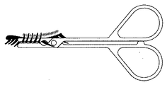
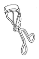
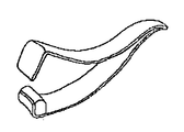
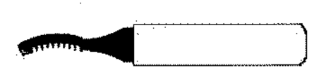
従来からよく知られているまつ毛カール器には主に、図5、図6に示す操作部を洋鋏状に開閉させることにより挟持部を接離させ、まつ毛を折り曲げ、まつ毛をカールさせるものと、図7に示す操作部をピンセット状に開閉させることにより挟持部を接離させ、まつ毛を折り曲げ、まつ毛をカールさせるもの、図8に示すまつ毛に熱を加え、まつ毛をカールさせるものがある。 Conventionally well-known eyelash curler mainly has an operation part shown in FIGS. 5 and 6 that opens and closes like a horsetail so that the holding part is brought into contact and separated, the eyelashes are bent, and the eyelashes are curled. 7 to open and close the operation part in a tweezers shape to make the clamping part contact and separate, to bend the eyelashes and curl the eyelashes, and to heat the eyelashes and to curl the eyelashes shown in FIG.
従来からよく知られている主なまつ毛カール器のうち、図5、図6、図7は、まつ毛を折り曲げ、まつ毛をカールさせるものである。図5は挟持部のカーブが目のカーブと合わないとまつ毛を挟持することができず、立体的で収納しにくい。また、図6、図7は、顔面に対して垂直方向に使用するため、まつ毛カール器と操作する手によって、鏡を顔面に近づけることができず、まつ毛と挟持部との距離を確認しにくい。そして図8はまつ毛に熱を加え、まつ毛をカールさせるもので、電源に主に電池を使用しているため重く、電池を入れ換える手間があるといった課題がある。 Among main eyelash curlers that have been well known in the past, FIGS. 5, 6, and 7 fold the eyelashes to curl the eyelashes. In FIG. 5, the eyelashes cannot be pinched unless the curve of the pinching part matches the curve of the eyes, and it is three-dimensional and difficult to store. 6 and 7 are used in a direction perpendicular to the face, the eyelash curler cannot be brought close to the face by the hand operating the eyelash curl device, and it is difficult to confirm the distance between the eyelashes and the clamping part. . FIG. 8 applies heat to the eyelashes to curl the eyelashes, and since the battery is mainly used for the power source, there is a problem that it is heavy and has the trouble of replacing the battery.
本発明のまつ毛カール器は、一端に操作部、他端にU字型若しくはU字型に似た断面形状でくぼみ部分に弾性材料が設置されている挟持部を有する移動部材と、一端に操作部、他端にU字型のくぼみ部分に入る厚さの平板状の挟持部を有する移動部材とを備え、両移動部材を軸部材で回転可能に枢結し、前記の操作部を洋鋏状に開閉させることにより、前記の挟持部を接離させまつ毛を挟持し折り曲げ、まつ毛をカールさせることができ、前記の挟持部がまつ毛を挟持したときに、顔面に対向する表面が、前記軸部材周りの回転面とほぼ平行となることを特徴とする機構となっている。 挟持部の長さは一般的な目の幅のおよそ3分の1とすると使い易い。 The eyelash curler of the present invention has an operation part at one end, a moving member having a clamping part in which an elastic material is installed in a recessed part with a U-shaped or U-shaped cross section at the other end, and an operation at one end And a moving member having a flat plate-shaped clamping part having a thickness that enters a U-shaped indentation part at the other end, both the moving members are pivotally connected by a shaft member, and the operation part is By opening and closing the lashes in a shape, the eyelashes can be contacted and separated, the eyelashes can be clamped and bent, and the eyelashes can be curled. The mechanism is characterized by being substantially parallel to the rotation surface around the member. It is easy to use if the length of the clamping part is about one third of the general eye width.
前記機構により本発明のまつ毛カール器は、顔面に対して水平方向に使用することになり、従来のまつ毛カール器である図6、図7よりも鏡を顔面に近づけることができるので、まつ毛と挟持部との距離を確認し易くなる。また、平面的で収納し易い、電池式としないことで軽いという利点もある。挟持部の長さを一般的な目の幅のおよそ3分の1にすると、位置や角度を変えながら繰り返し挟持することにより、様々な目のカーブに対応し易い。 With the above mechanism, the eyelash curl of the present invention is used in a horizontal direction with respect to the face, and the mirror can be brought closer to the face than the conventional eyelash curlers of FIGS. 6 and 7. It becomes easy to confirm the distance with the clamping part. In addition, there is an advantage that it is light by not being a battery type because it is flat and easy to store. If the length of the sandwiching portion is set to about one third of the general eye width, it is easy to cope with various eye curves by repeatedly sandwiching while changing the position and angle.
以下、本発明の実施の形態について図を参照して詳細を説明する。 Hereinafter, embodiments of the present invention will be described in detail with reference to the drawings.
図1、図2に示すように本発明のまつ毛カール器1は、一端に指を掛ける操作部2a、3a、他端にまつ毛を挟む挟持部2b、3bが形成された移動部材2、3からなる。移動部材2、3は軸部材4によって回転可能に枢結されている。 As shown in FIG. 1 and FIG. 2, the
移動部材2の操作部2aは指を掛けられるようにリングの形状になっている。挟持部2bについてはU字型若しくはU字型に似た断面で、挟持部3bとの間でまつ毛を弾性的に挟持できるよう、くぼみ部分にはゴム等の弾性材料2dが設置されている。 The operation part 2a of the moving
移動部材3の操作部3aは2aと同様にリングの形状になっており、閉じすぎ防止のストッパー部3dを備えている。挟持部3bは平板状で、挟持部2bのくぼみ部分に入る厚さになっており、挟持部が近接したときに、くぼみ部分に納まる位置にある。 The operation portion 3a of the moving
軸部材4は軸部材周辺部2cと軸部材周辺部3cの位置で移動部材2、3を回転可能に枢結している。 The shaft member 4 pivotally connects the moving
次に、本発明のまつ毛カール器1の使用方法について説明する。 Next, the usage method of the
図2に示すように、操作部2a、3aを軸部材4を支点にして開き、挟持部2b、3bを離し間にまつ毛を介在させた後、操作部2a、3aを軸部材4を支点にして閉じ、挟持部2b、3bを近接させ、図4に示すようにまつ毛を挟持して折り曲げ、カールさせる。前記の動作を位置や角度を変えて繰り返し行うことで、まつ毛全体をカールさせる。 As shown in FIG. 2, the operation parts 2a and 3a are opened with the shaft member 4 as a fulcrum, and the holding parts 2b and 3b are separated and the eyelashes are interposed therebetween, and then the operation parts 2a and 3a are used with the shaft member 4 as a fulcrum. Then, the clamping parts 2b and 3b are brought close to each other, and the eyelashes are clamped and bent and curled as shown in FIG. The entire operation of the eyelashes is curled by repeating the above operation while changing the position and angle.
1 まつ毛カール器
2 移動部材
2a 操作部
2b U字型若しくはU字型に似た断面の挟持部
2c 軸部材周辺部
2d ゴム等の弾性材料
3 移動部材
3a 操作部
3b 平板状の挟持部
3c 軸部材周辺部
3d ストッパー部
4 軸部材DESCRIPTION OF
Claims (1)
Priority Applications (1)
| Application Number | Priority Date | Filing Date | Title |
|---|---|---|---|
| JP2011128669A JP5769147B2 (en) | 2011-01-12 | 2011-05-24 | Eyelash curler |
Applications Claiming Priority (3)
| Application Number | Priority Date | Filing Date | Title |
|---|---|---|---|
| JP2011015758 | 2011-01-12 | ||
| JP2011015758 | 2011-01-12 | ||
| JP2011128669A JP5769147B2 (en) | 2011-01-12 | 2011-05-24 | Eyelash curler |
Publications (2)
| Publication Number | Publication Date |
|---|---|
| JP2012157681A true JP2012157681A (en) | 2012-08-23 |
| JP5769147B2 JP5769147B2 (en) | 2015-08-26 |
Family
ID=46838716
Family Applications (1)
| Application Number | Title | Priority Date | Filing Date |
|---|---|---|---|
| JP2011128669A Active JP5769147B2 (en) | 2011-01-12 | 2011-05-24 | Eyelash curler |
Country Status (1)
| Country | Link |
|---|---|
| JP (1) | JP5769147B2 (en) |
Cited By (1)
| Publication number | Priority date | Publication date | Assignee | Title |
|---|---|---|---|---|
| WO2015054743A1 (en) * | 2013-10-18 | 2015-04-23 | Barber Cindy Jane | Eyelash curler |
Citations (12)
| Publication number | Priority date | Publication date | Assignee | Title |
|---|---|---|---|---|
| US1920401A (en) * | 1932-11-05 | 1933-08-01 | Edgar E Kahn | Eyelash curler |
| US1987931A (en) * | 1933-05-27 | 1935-01-15 | Delamere Co Inc | Eyelash curler |
| GB435233A (en) * | 1934-11-09 | 1935-09-17 | Jacob Goodman | Eyelash curlers |
| JPS60147301U (en) * | 1984-03-12 | 1985-09-30 | 窪川 正道 | Permanent eyelash curler |
| JPS61122701U (en) * | 1985-01-18 | 1986-08-02 | ||
| US5007442A (en) * | 1988-01-11 | 1991-04-16 | Hirzel Suzy C | Double blocking members sealing a single opening means |
| US5176156A (en) * | 1991-05-24 | 1993-01-05 | Ashtary Parvis N | Mascara applicator and eyelash brushing and curling device |
| WO2004077987A1 (en) * | 2003-03-05 | 2004-09-16 | Laline International Sarl | Mascara applicator with movable arms |
| WO2004082425A1 (en) * | 2003-03-19 | 2004-09-30 | Tensen Tahara | Cosmetic tool for lash |
| FR2897760A1 (en) * | 2006-02-24 | 2007-08-31 | Georges Jean Demichelis | Mascara brush for e.g. combing eyelashes, has brushes formed of respective bristle portions and superposed on one another, where portions are curved, concave, convex and plane and are integrated to solid and rigid non-bristled parts |
| US20100095975A1 (en) * | 2007-05-16 | 2010-04-22 | Cpi Korea, Inc. | Curling mascara |
| US20100300473A1 (en) * | 2009-06-01 | 2010-12-02 | Tae Jin Kim | Mascara container with curling tongs |
-
2011
- 2011-05-24 JP JP2011128669A patent/JP5769147B2/en active Active
Patent Citations (12)
| Publication number | Priority date | Publication date | Assignee | Title |
|---|---|---|---|---|
| US1920401A (en) * | 1932-11-05 | 1933-08-01 | Edgar E Kahn | Eyelash curler |
| US1987931A (en) * | 1933-05-27 | 1935-01-15 | Delamere Co Inc | Eyelash curler |
| GB435233A (en) * | 1934-11-09 | 1935-09-17 | Jacob Goodman | Eyelash curlers |
| JPS60147301U (en) * | 1984-03-12 | 1985-09-30 | 窪川 正道 | Permanent eyelash curler |
| JPS61122701U (en) * | 1985-01-18 | 1986-08-02 | ||
| US5007442A (en) * | 1988-01-11 | 1991-04-16 | Hirzel Suzy C | Double blocking members sealing a single opening means |
| US5176156A (en) * | 1991-05-24 | 1993-01-05 | Ashtary Parvis N | Mascara applicator and eyelash brushing and curling device |
| WO2004077987A1 (en) * | 2003-03-05 | 2004-09-16 | Laline International Sarl | Mascara applicator with movable arms |
| WO2004082425A1 (en) * | 2003-03-19 | 2004-09-30 | Tensen Tahara | Cosmetic tool for lash |
| FR2897760A1 (en) * | 2006-02-24 | 2007-08-31 | Georges Jean Demichelis | Mascara brush for e.g. combing eyelashes, has brushes formed of respective bristle portions and superposed on one another, where portions are curved, concave, convex and plane and are integrated to solid and rigid non-bristled parts |
| US20100095975A1 (en) * | 2007-05-16 | 2010-04-22 | Cpi Korea, Inc. | Curling mascara |
| US20100300473A1 (en) * | 2009-06-01 | 2010-12-02 | Tae Jin Kim | Mascara container with curling tongs |
Cited By (2)
| Publication number | Priority date | Publication date | Assignee | Title |
|---|---|---|---|---|
| WO2015054743A1 (en) * | 2013-10-18 | 2015-04-23 | Barber Cindy Jane | Eyelash curler |
| US11540608B2 (en) | 2013-10-18 | 2023-01-03 | Cindy Jane Barber | Eyelash curler |
Also Published As
| Publication number | Publication date |
|---|---|
| JP5769147B2 (en) | 2015-08-26 |
Similar Documents
| Publication | Publication Date | Title |
|---|---|---|
| RU2014145623A (en) | HAIR STYLING DEVICE | |
| RU2685095C2 (en) | Hair styling device for forming ringlets of various sizes | |
| WO2013084964A1 (en) | Mascara applicator | |
| AU2016100897A4 (en) | Heated hair curling device with retainer arm | |
| MXPA05011236A (en) | Hair iron having buffer member. | |
| US8863761B2 (en) | Clipping device | |
| JP2012157681A (en) | Eyelash curler | |
| KR200476931Y1 (en) | Hair pin | |
| US9839275B2 (en) | Parting comb | |
| JP3156237U (en) | Hair clip | |
| JP3161543U (en) | Hair clip | |
| JP5903618B2 (en) | Curling iron | |
| KR101427048B1 (en) | Hair clip | |
| JP3160599U (en) | Eyelash curler with a synthetic resin cushion attached to the handle | |
| JP5904396B2 (en) | Cosmetic application body | |
| JP3196950U (en) | hair iron | |
| JP3177337U (en) | Hair iron | |
| JP2013066582A (en) | Container | |
| JP2012090794A (en) | Hair clip | |
| JP2019188103A (en) | Nail cover | |
| JP3166682U (en) | Eyelash curler with multiple magnets attached to the handle in the direction of magnetic repulsion | |
| JP2013220279A (en) | Hair iron | |
| JP3174280U (en) | Eyelash curler characterized by pinching and curling the eyelashes with a hinge structure | |
| JP3100570U (en) | Hair clip | |
| JP3197495U (en) | Hair curler |
Legal Events
| Date | Code | Title | Description |
|---|---|---|---|
| A621 | Written request for application examination |
Free format text: JAPANESE INTERMEDIATE CODE: A621 Effective date: 20140428 |
|
| A977 | Report on retrieval |
Free format text: JAPANESE INTERMEDIATE CODE: A971007 Effective date: 20141212 |
|
| A131 | Notification of reasons for refusal |
Free format text: JAPANESE INTERMEDIATE CODE: A131 Effective date: 20150106 |
|
| A521 | Written amendment |
Free format text: JAPANESE INTERMEDIATE CODE: A523 Effective date: 20150325 |
|
| TRDD | Decision of grant or rejection written | ||
| A01 | Written decision to grant a patent or to grant a registration (utility model) |
Free format text: JAPANESE INTERMEDIATE CODE: A01 Effective date: 20150512 |
|
| A61 | First payment of annual fees (during grant procedure) |
Free format text: JAPANESE INTERMEDIATE CODE: A61 Effective date: 20150615 |
|
| R150 | Certificate of patent or registration of utility model |
Ref document number: 5769147 Country of ref document: JP Free format text: JAPANESE INTERMEDIATE CODE: R150 |
|
| R250 | Receipt of annual fees |
Free format text: JAPANESE INTERMEDIATE CODE: R250 |