JP2012148003A - Tomographic imaging apparatus - Google Patents
Tomographic imaging apparatus Download PDFInfo
- Publication number
- JP2012148003A JP2012148003A JP2011010150A JP2011010150A JP2012148003A JP 2012148003 A JP2012148003 A JP 2012148003A JP 2011010150 A JP2011010150 A JP 2011010150A JP 2011010150 A JP2011010150 A JP 2011010150A JP 2012148003 A JP2012148003 A JP 2012148003A
- Authority
- JP
- Japan
- Prior art keywords
- light
- optical path
- optical
- path length
- inspection object
- Prior art date
- Legal status (The legal status is an assumption and is not a legal conclusion. Google has not performed a legal analysis and makes no representation as to the accuracy of the status listed.)
- Granted
Links
Images


Classifications
-
- A—HUMAN NECESSITIES
- A61—MEDICAL OR VETERINARY SCIENCE; HYGIENE
- A61B—DIAGNOSIS; SURGERY; IDENTIFICATION
- A61B3/00—Apparatus for testing the eyes; Instruments for examining the eyes
- A61B3/10—Objective types, i.e. instruments for examining the eyes independent of the patients' perceptions or reactions
- A61B3/102—Objective types, i.e. instruments for examining the eyes independent of the patients' perceptions or reactions for optical coherence tomography [OCT]
Abstract
Description
本発明は、断層画像撮像装置に関し、特に、眼底などの観察に用いられる光干渉断層法を用いる断層画像撮像装置に関する。 The present invention relates to a tomographic imaging apparatus, and more particularly to a tomographic imaging apparatus using an optical coherence tomography method used for observation of the fundus and the like.
現在、低コヒーレント光による干渉を利用した光干渉断層法(OCT:Optical Coherence Tomography)を用いる撮像装置(以下、OCT装置とも呼ぶ。)が実用化されている。これは、被検査物に入射する光の波長程度の分解能で断層画像を取得できるため、被検査物の断層画像を高解像度に撮像することができる。 Currently, an imaging apparatus (hereinafter also referred to as an OCT apparatus) using optical coherence tomography (OCT) using interference by low-coherent light has been put into practical use. This is because a tomographic image can be acquired with a resolution approximately equal to the wavelength of light incident on the inspection object, so that a tomographic image of the inspection object can be captured with high resolution.
OCT装置において、光源からの光は、ビームスプリッタなどにより、測定光と参照光とに分けられる。測定光は、測定光路を介して眼などの被検査物に照射される。そして、被検査物からの戻り光は参照光と合波され、干渉光として検出光路を介して検出器に導かれる。ここで、戻り光とは、被検査物に対する光の照射方向における界面に関する情報等が含まれる反射光や散乱光のことである。戻り光と参照光との干渉光を検出器で検出し、解析することによって被検査物の断層画像を得ることができる。 In the OCT apparatus, light from a light source is divided into measurement light and reference light by a beam splitter or the like. The measurement light is irradiated to an object such as an eye through the measurement optical path. Then, the return light from the object to be inspected is combined with the reference light and guided as interference light to the detector via the detection light path. Here, the return light is reflected light or scattered light including information on the interface in the light irradiation direction with respect to the inspection object. A tomographic image of the object to be inspected can be obtained by detecting and analyzing the interference light between the return light and the reference light with a detector.
OCT装置は、眼底の網膜の断層画像を撮像するために用いられることが多いが、眼底を広く撮像し、眼球の形状を求める方法も知られている。(特許文献1)
しかし、このようにして求めた眼球の形状は、OCTの原理に基づいて形成された断層画像から演算しているため屈折率の情報を含む光学的な距離を示しており、実形状・実寸法を示してはいなかった。
The OCT apparatus is often used to capture a tomographic image of the retina of the fundus. However, a method is also known in which the fundus is imaged widely and the shape of the eyeball is obtained. (Patent Document 1)
However, the shape of the eyeball obtained in this way is calculated from a tomographic image formed based on the principle of OCT, and thus indicates an optical distance including information on the refractive index. Did not show.
上述した網膜等の断層画像について、実形状及び実寸法を表示可能となる本発明に係る断層画像撮像装置は、光を発生させるための光源、光源からの光を、参照光と測定光とに分岐するための光分岐手段、参照光の光路長を調整する調整手段、測定光を被検査物に照射することにより得られる戻り光と参照光との合波光を分光して合波光から干渉信号を取得する分光手段、被検査物の断層画像の撮像を行う際の光路長を検出する検出手段、被検査物の光学的な情報に関するデータを記憶する記憶手段、及び光路長及び被検査物の光学的な情報に関するデータを用いて、分光手段で取得した干渉信号から画像データを演算する演算手段、を有することを特徴としている。 The tomographic image capturing apparatus according to the present invention that can display the actual shape and actual dimensions of the above-described tomographic image of the retina or the like includes a light source for generating light, light from the light source as reference light and measurement light. An optical branching means for branching, an adjusting means for adjusting the optical path length of the reference light, a combined light of the return light and the reference light obtained by irradiating the inspection light with the measurement light, and an interference signal from the combined light Spectroscopic means for obtaining the tomographic image of the inspection object, detection means for detecting the optical path length when taking a tomographic image, storage means for storing data relating to optical information of the inspection object, and optical path length and the inspection object It has a calculation means for calculating image data from the interference signal acquired by the spectroscopic means using data relating to optical information.
本発明によれば、被検査物の実寸法・実形状に近い断層画像データを得ることができる。 According to the present invention, it is possible to obtain tomographic image data close to the actual size and shape of the inspection object.
[第1の実施形態]
本発明の実施形態について図面を参照しながら、以下に詳細に説明する。本実施形態の装置により撮像できるものは、例えば、人間の網膜、前眼部等の断層画像である。
また、以下の実施形態における被検眼は本発明における被検査物に、網膜は被検査領域に対応し、眼軸は被検査物の光軸に対応する。
[First Embodiment]
Embodiments of the present invention will be described in detail below with reference to the drawings. What can be imaged by the apparatus of the present embodiment is, for example, a tomographic image of a human retina, anterior eye portion, or the like.
In the following embodiments, the eye to be inspected corresponds to the object to be inspected in the present invention, the retina corresponds to the inspected area, and the eye axis corresponds to the optical axis of the inspected object.
(装置構成)
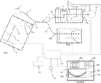
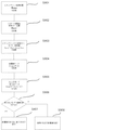
本実施形態に係るフーリエドメイン方式の光干渉断層法を眼底撮像装置に応用した例について、図1を用いて説明する。
(Device configuration)
An example in which the Fourier domain optical coherence tomography according to the present embodiment is applied to a fundus imaging apparatus will be described with reference to FIG.
1は、光(低コヒーレンス光)を発生させるための光源であって、本発明の光源手段に対応する。本実施形態において光源1には、中心波長850nm、帯域50nmのSLD(Super Luminescent Diode)光源を用いる。なお、光源1には、ASE(Amplified Spontaneous Emission)光源も適用することができる。また、光源1には、チタンサファイアレーザなどの超短パルスレーザ光源も適用することができる。このように、光源1は、低コヒーレンス光を発生させることの出来るものなら何でも良い。さらに、光源1から発生する光の波長は、特に制限されるものではないが、被検査物に応じて400nmから2μmの範囲で選択される。波長の帯域は広いほど縦分解能がよくなる。一般的に中心波長が850nmの場合、50nmの帯域では6μmの縦分解能、100nmの帯域では3μmの縦分解能である。 Reference numeral 1 denotes a light source for generating light (low coherence light), which corresponds to the light source means of the present invention. In this embodiment, an SLD (Super Luminescent Diode) light source having a center wavelength of 850 nm and a bandwidth of 50 nm is used as the light source 1. An ASE (Amplified Spontaneous Emission) light source can also be applied to the light source 1. The light source 1 can also be an ultrashort pulse laser light source such as a titanium sapphire laser. As described above, the light source 1 may be anything that can generate low-coherence light. Further, the wavelength of light generated from the light source 1 is not particularly limited, but is selected in the range of 400 nm to 2 μm depending on the object to be inspected. The wider the wavelength band, the better the vertical resolution. In general, when the center wavelength is 850 nm, the vertical resolution is 6 μm in the 50 nm band and 3 μm in the 100 nm band.
2、4、10、14は、光ファイバー等で構成される導光部である。光源1を発した光束は、導光部2により光分岐部3に導かれる。光分岐部3は、ファイバーカプラなどを適用することができ、本発明における光分岐手段に対応する。なお、分岐の比率は被検査物に合わせて適切なものを選択する。
光分岐部3により導光部4側に分岐された光路上には、コリメータレンズ5、光走査部6、フォーカスレンズ7、波長分岐ミラー8、対物レンズ9が配置され、サンプルアーム1001を構成する。光走査部6は、光軸方向に隣接して配置(タンデム配置)された互いに直交するX,Y方向に光をそれぞれ走査するガルバノミラー又は共振ミラー等が適用される。波長分岐ミラー8は、光源1を発した光(波長:λ=800〜900nm)を透過し、前眼部照明の光(λ=940nm)を反射する。導光部4に導かれた光は、測定光としてサンプルアーム1001を通り被検眼Eの眼底Efに達する。
A collimator lens 5, an
光分岐部3により導光部10側に分岐された光路上にはコリメータレンズ11、参照ミラー12が配置され参照アーム1002を構成する。参照ミラー12は、直動ステージ13上に配置され、直動ステージ13を光軸方向に移動することにより、参照アーム1002の光路長を調整する。参照ミラー12及び直動ステージ13は、後述する制御部19と共に本発明における参照光の光路長を調整する調整手段に対応する。
A collimator lens 11 and a
レンズ15、回折格子であるグレーティングやプリズム等で構成される分光部16、結像レンズ17、CMOSやCCD等の光電変換素子を有する撮像部18は、分光器1003を構成する。光分岐部3に接続された導光部14により、光分岐部3からの光は分光器1003に導かれる。19は制御部であり、光走査部6、直動ステージ13、撮像部18等の制御を行う。また、制御部19には表示部20が接続されている。
A
対物レンズ9の周りには 前眼部照明光源21a,21bが配置され、これらの光源により照明された被検眼Eの前眼部の像は、対物レンズ9を通り、波長分岐ミラー8により反射され、レンズ22により二次元の撮像部23の撮像面に結像する。また、制御部19には、メモリー24、マウス等のポインティングデバイス25が接続されている。
Anterior segment illumination light sources 21a and 21b are disposed around the objective lens 9, and an image of the anterior segment of the eye E illuminated by these light sources passes through the objective lens 9 and is reflected by the
(測定方法)
次にこのような構成の装置を用いて、被検眼Eの眼底Efの網膜の断層画像を撮像する方法、即ち断層画像撮像方法を説明する。
被検眼Eを本装置の前に配置すると、被検眼Eの前眼部は光源21a,21bを発した光により照明される。このように照明された前眼部の像は、対物レンズ9を通り、波長分岐ミラー8により反射されて、レンズ22により、撮像部23の撮像面に結像する。撮像部23からの映像信号は、制御部19に入力されデジタルデータにリアルタイムに変換され、前眼部像が生成される。制御部19は、この被検眼Eの前眼部像のうちの特に虹彩の模様より、被検眼Eの偏心及び、ピントの状態を判定する。撮像面の中心とサンプルアーム1001の光学系の光軸が一致するように調整されているため、撮像部23で撮像された前眼部像の瞳孔中心と撮像中心の偏心量が被検眼Eとサンプルアーム1001の光学系の偏心量に相当する。サンプルアーム1001の光学系は、被検眼Eに対し、上下左右、さらに光軸方向に位置調整可能に不図示のステージ上に配置されている。したがって、前述の通り、瞳孔中心と光軸が一致するように、上下左右の位置を調整し、虹彩の模様のコントラストが最も高くなるように、光軸方向の位置調整を行う。これにより、虹彩と同一面である被検眼Eの瞳孔Epとサンプルアーム1001の光学系の対物レンズ9との距離(ワーキングディスタンス)は一定に保たれている。前眼部像は、表示部20の表示領域20aに表示され、操作者は、この画像により光軸偏心を確認することができる。
(Measuring method)
Next, a method for capturing a tomographic image of the retina of the fundus oculi Ef of the eye E to be examined, that is, a tomographic image capturing method will be described.
When the eye E is placed in front of the present apparatus, the anterior eye portion of the eye E is illuminated with light emitted from the light sources 21a and 21b. The image of the anterior segment illuminated in this way passes through the objective lens 9, is reflected by the
このように、オートアライメントにより偏心量が所定の値以下になると、光源1を点灯し、アライメント用の断層画像の撮像を開始する。光源1からの光は、導光部2により光分岐部3に導かれ、導光部4と導光部10に導かれる光量の比が、例えば1:9になるように分岐される。導光部4側に導かれた測定光は、ファイバー端4aに達する。ファイバー端4aを点光源として発した測定光は、コリメータレンズ5により平行光に変換され、走査部6のXスキャンミラーにより走査される。平行光とされた測定光は、フォーカスレンズ7、波長分岐ミラー8を透過し対物レンズ9により被検眼Eの瞳孔より眼底Efに照射され、眼底Ef上を走査される。
As described above, when the amount of eccentricity becomes equal to or less than a predetermined value by auto-alignment, the light source 1 is turned on and imaging of a tomographic image for alignment is started. The light from the light source 1 is guided to the
眼底Efの網膜を構成する複数の層で反射・散乱された戻り光は、入射時と同一の光路を戻り、コリメータレンズ5を経てファイバー端4aより導光部4に入り、光分岐部3に導かれる。導光部14を経てファイバー端14aを出射した戻り光は、コリメータレンズ15により平行光に変換され、分光部16に入射する。分光部16には、測定光の波長に近い寸法の回折格子が等間隔に数多く形成されており、入射した戻り光を回折により分光する。
The return light reflected and scattered by a plurality of layers constituting the retina of the fundus oculi Ef returns to the same optical path as that at the time of incidence, enters the light guide unit 4 from the fiber end 4a through the collimator lens 5, and enters the
回折角度は波長により異なるため、回折された戻り光は、結像レンズ17により線像として撮像部18のライン状の撮像領域に結像する。すなわちファイバー端14aを出射した戻り光は、分光されたスリット像として結像する。したがって撮像部18からは、波長毎の強度に対応した信号が出力される。これらの戻り光と参照光とを合波して合波光を生成する光分岐部3等の構成、該合波光を分光する分光部16等の構成、及び該合波光から干渉信号を生成する撮像部18等の構成は、本発明の分光手段に対応する。
Since the diffraction angle varies depending on the wavelength, the diffracted return light is imaged as a line image by the
また、光分岐部3より導光部10に導かれた参照光は、ファイバー端10aから出射されレンズ11により平行光に変換され参照ミラー12に向かう。参照ミラー12は、平行光である参照光の光軸と垂直に、また、該光軸の方向に移動可能に直動ステージ13上に配置されている。これにより異なる眼軸長の被検眼Eに対しても、参照光の光路と測定光の光路の光路長とをあわせることができる。操作者は表示部20上の表示領域20dを、ポインティングデバイス25を操作してカーソルで指示することにより、参照ミラー12の位置を調整することができる。参照ミラー12で反射された参照光は、レンズ11により導光部10のファイバー端10aに集光され、導光部10により光分岐部3を介して導光部14に導かれる。そして、導光部14に導かれた光は、眼底Eからの戻り光との合波光となり、分光器1003に入り、前述の様に、分光部16により分光され撮像部18の光電変換素子がライン上に配列する受光領域に結像する。撮像部18からの信号は、制御部19に入力され、断層画像が生成され表示部20の表示領域20bに表示される。操作者は、この断層画像を観察し、断層画像が最も明るくなるようにポインティングデバイス25を用いてカーソルで表示領域20cのボタンを操作してフォーカス調整を行う。また、同様に、表示領域20bの所望の領域内に関心部位の断層画像が全て入るように表示領域20dのボタンを操作して参照ミラー12の位置調整(コヒーレンスゲート調整)を行う。表示領域20dが指示されると制御部19は、直動ステージ13の位置を指示された方向に移動させるとともに、メモリー24に記憶している直動ステージ13の制御位置情報を移動量に応じて変更する。直動ステージは、不図示のステッピングモータにより駆動制御されており、直動ステージ13の位置は、ステッピングモータに指示するステップ数と対応している。例えば、60mmのストロークを60000ステップで駆動する場合1ステップあたりの移動量は1μmになる。0-60000までのステップ数が、直動ステージの0から60mmの位置に対応する。またこの直動ステージ13の基準位置からレンズ11までの距離は設計的に精度よく配置されておりこの基準位置と前記ステージ位置の関係も設計的に明らかであるため、このステップ数より参照光の光路長を計算することができる。制御部19は、不図示のステッピングモータのステップ数により光路長を検出する、本発明における検出手段に対応する。このように参照ミラー12の位置の変化とともに、参照光の光路長が変化する。これにより表示領域20b内の断層画像の表示位置が変化する。このように、断層画像の撮像時における参照ミラー12の位置は常にメモリー24に記憶されている。以上の撮像準備の後、撮像ボタン20eが指示されると、断層画像の静止画撮像(断層画像撮像)を行う。これにより、撮像された断層画像は、メモリー24に記憶される。
The reference light guided from the
(断層画像生成)
次に断層画像の生成について説明する。
導光部14には、被検眼Eの眼底Efからの戻り光と、参照ミラー12から反射された参照光との合波光が導かれる。光分岐部3から眼底Efまでの光路長と、光分岐部3から参照ミラー12までの光路長の差により、光分岐部3で合波されるとき戻り光と参照光は、位相差を有する。この位相差は波長により異なるため、撮像部18の受光領域18a上に現れる分光強度分布には干渉縞が生じる。また、網膜には複数の層があり、それぞれの層境界からの戻り光はそれぞれ異なる光路長を有するため、干渉縞には、異なる周波数の干渉縞が含まれる。この強度分布に含まれる干渉縞の周波数とその強度より、反射物体の位置とその位置からの反射・散乱に対応した明るさを求めることができる。
(Tomographic image generation)
Next, generation of a tomographic image will be described.
The
眼底上の1ラインをスキャンするBスキャンモードにおいては、制御部19は、光走査部6のX、Yのスキャンミラーの一つ、例えば、Xスキャンミラーだけを駆動しながら、撮像部18からの出力を読み出す。走査部6からは、スキャンミラーの角度を示すデータが出力されており、読み出された信号はスキャンミラーの角度と共にデジタルデータに変換され、さらに光が被検眼に入射する角度θiに変換されてメモリー24に記憶される。スキャンミラーの角度と光線の入射角θiは、対応しており、光学系の設計値より求める。なお、該入射角θiは被検眼に入射する測定光と被検眼の眼軸とが成す第一の角の角度に対応する。
In the B scan mode for scanning one line on the fundus, the
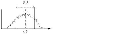
図2は、スキャンミラーの角度θiにおける撮像部18上の光の強度分布を示す。横軸は、撮像部18上のセンサー位置であり、波長に対応する。縦軸は、信号強度である。ここでは、中心波長λ0、半値幅δλの強度分布に対して、干渉縞による波形が重なっている。 FIG. 2 shows the light intensity distribution on the imaging unit 18 at the scan mirror angle θi. The horizontal axis is the sensor position on the imaging unit 18 and corresponds to the wavelength. The vertical axis represents the signal intensity. Here, the waveform due to the interference fringes overlaps the intensity distribution of the center wavelength λ 0 and the half-value width δλ.
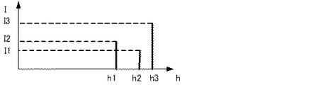
この波形の強度情報を読み出し、A/D変換器によりデジタルデータに変換し、メモリー24に記憶する。このデータを波数変換し、周波数変換すると図3に示すような強度分布が得られる。これは図4に示すようにh1,h2,h3の距離(コヒーレンスゲートからの距離)のところの干渉強度がI2,I1,I3であることを示す。したがって、スキャンミラーの角度θiを、θsからθeまで変化させながら、干渉強度を測定する。このように取得した干渉強度I(θi,hj) を、θを横軸、hを縦軸にして表示することにより図4に示すように眼底のBスキャン画像(光学的な距離に基づく画像)を表示することができる。
The intensity information of this waveform is read out, converted into digital data by an A / D converter, and stored in the
(形状計測)
図5に眼底をBスキャンする場合に眼底に到る光線(測定光)を示す。入射角θiで、角膜61より被検眼Eに入射した光線は、被検眼Eの内部の、瞳孔62の中央部、水晶体63、硝子体64を通り眼底65へ向かい網膜の各層で反射・散乱される。被検眼Eとサンプルアーム1001の光学系の距離がオートアライメント機能により適切に保たれている場合には、Xスキャンミラーは、瞳孔62と共役に設計されているため、Xスキャンミラーのスキャン角度が変化しても、光線は常に瞳孔62の中央部を通る。この点をピボットポイントという。該ピボットポイントは、被検眼Eの内部に測定光を入射させ且つ網膜上で測定光を走査した場合であっても該測定光が常に通過する位置に対応する。すなわち、該ピボットポイントは、被検眼Eの内部の網膜上での測定光を走査する場合の、本発明において、被検眼Eに対する測定光の入射点に対応する。66は、参照光学系の光路長と同じ距離になる位置、すなわち参照ミラーの位置と等価な位置(コヒーレンスゲート)を示す。つまり、干渉信号より求めた距離h1・h2・h3は、この参照ミラー位置66と各網膜層との距離に相当する。
(Shape measurement)
FIG. 5 shows light rays (measurement light) reaching the fundus when the fundus is B-scanned. A light beam incident on the eye E from the
眼軸長が異なる被検眼を撮像する場合には、ステージ13を調整して、参照ミラー12の位置を、眼軸長に合わせて調整することにより測定を行うことができる。
When imaging an eye to be examined having a different axial length, measurement can be performed by adjusting the stage 13 and adjusting the position of the
ところで、図4に示した断層画像から得られる眼底の形状と実際の眼球の形状は次の点で異なる。
(1)演算で求めた距離hjは、真空中を同じ時間で光が進む光学的な距離(光路長=距離×屈折率)であり、実際の距離とは異なる。
(2)図4では、スキャンミラーの角度に対応したデータを、平行に並べて画像を作成したが、実際には、これらの画像データは、スキャンの中心(ピボットポイント)を中心とする極座標上に表されるべき画像データである。
(3)角度θiは、光線の入射角であり眼の中の走査角とは異なる。
すなわち、以上の点を補正することにより実寸法に近い値の眼球の形状をもとめることができる。
Incidentally, the fundus shape obtained from the tomographic image shown in FIG. 4 differs from the actual eyeball shape in the following points.
(1) The distance hj obtained by calculation is an optical distance (light path length = distance × refractive index) in which light travels in the same time in a vacuum, and is different from an actual distance.
(2) In FIG. 4, data corresponding to the angle of the scan mirror is arranged in parallel, and an image is created. However, in reality, these image data are on polar coordinates centered on the center of the scan (pivot point). Image data to be represented.
(3) The angle θi is the incident angle of the light beam and is different from the scanning angle in the eye.
That is, by correcting the above points, the shape of the eyeball having a value close to the actual size can be obtained.
(光路長の補正)
Bスキャン画像上の点の明るさは、図4に示した通り、スキャンミラーの角度θiと参照光学系の光路長との差分であるhjをパラメータとしてImage(θi,hj)で表すことができる。ただし、これだけの情報では、実際の形状を求めることはできない。hjは、コヒーレンスゲート66からの距離であり、実際の形状を求めるためにはこのコヒーレンスゲート面(CG面)の形状(曲率半径)を求める必要がある。図9を参照し、実際の形状を求める処理について説明する。
(Optical path length correction)
As shown in FIG. 4, the brightness of the point on the B-scan image can be expressed by Image (θi, hj) using hj, which is the difference between the scan mirror angle θi and the optical path length of the reference optical system as a parameter. . However, the actual shape cannot be obtained with such information. hj is a distance from the coherence gate 66, and in order to obtain the actual shape, it is necessary to obtain the shape (curvature radius) of the coherence gate surface (CG surface). With reference to FIG. 9, the process for obtaining the actual shape will be described.
(CG面の曲率半径)
この曲率半径は、ピボットポイントから、コヒーレンスゲート66までの距離より求める。この距離は、ピボットポイントに相当する参照ミラー12の位置に相当するステップ数を設計値より求め、実際に撮像した際の参照ミラー12の位置を示すステップ数との差分より求めることができる。また、次の方法で実測することも可能である。対物レンズの前、ピボットポイントにミラーを光軸に垂直に配置し、反射光が直接光学系に戻るようにする。この光は、参照ミラー12からの戻り光と干渉する。操作スイッチ20dによりステージ13を駆動して参照ミラー12を移動し、干渉信号の周波数が最も小さくなる位置つまり、光路長の一致する位置Rmoxをもとめる。その時のステージ位置を示すステップ数を参照ミラーの原点としてメモリー24に記憶する(ステップS901)。
(Curved radius of CG surface)
This curvature radius is obtained from the distance from the pivot point to the coherence gate 66. This distance can be obtained from the difference between the number of steps corresponding to the position of the
次に、被検眼Eの断層画像データを取得する。被検眼Eを被検眼の形状が画面内に表示されるように、参照ミラー12の位置を調整する。このとき、参照光の光路長を測定光の光路長より短くして取る撮像方法(正像)と参照光の光路長の方を長くする撮像方法(逆像)があるが、逆像の撮像方法について説明する。断層画像をリアルタイムに画像化するアライメント画面を用いて、被検眼の網膜の断層画像が、CG面の近傍に位置するように、参照ミラー12の載ったステージ13の位置を調整する。前記の通りステージの位置を示すステップ数を参照ミラーの位置Rm1とする(ステップS902)。すなわち、(Rm1-Rmox)×α=RmxLがピボットポイントからコヒーレンスゲート66までの距離である(αは、1ステップに対応する距離)。ただし、RmxLから求めた距離は、光学的な距離であり、被検眼内での実距離とは異なる。このRmxLから前述した距離を求める工程は、本発明における光断層画像撮像方法における、断層画像を取得する際において参照光の光路長に対応する光路長となる測定光の光路上の第一の位置を取得する工程に対応する。なお、この第一の位置は、光学的に求められる値からなる。硝子体64の屈折率Nvitは、略水と同じ(≒1.34)と測定されており、空気中を進む参照光路に対し光の進む速さは遅い。光の進む速さの比は、屈折率の逆数に比例するため、光が空気中の距離RmxLを進む間に硝子体中を進む距離をRmxL’とすると、RmxL’=RmxL/Nvit =(Rm1-Rmox)/Nvitである(ステップS903)。したがって、コヒーレンスゲート66の半径はRmxL’である。このように参照ミラー12の位置を検知することにより、参照ミラー12と等価な面(コヒーレンスゲート面)の形状がわかるため実寸法による網膜形状を求めることができる。次に操作者は、表示部上の撮影スイッチ20eを操作する。これにより制御部19は、撮像部18からの信号より前述の通り断層画像を演算し、断層画像データImage(θi,hj)をメモリー24に記憶する(ステップ904)。同様にコヒーレンスゲート相当面から網膜層までの実距離hj’は、測定により求められた距離hj、硝子体屈折率 Nvitを用いて、hj’ = hj/Nvit である。
Next, tomographic image data of the eye E is acquired. The position of the
(スキャン角度)
次に眼球を実際に走査する角度θ’を求める計算方法について説明する。被検眼Eへの光の入射角θiは、スキャンミラーの走査角より決まるが、眼内での実際の走査角θi’は参照ミラー12の位置を基準として求めた被検眼の眼軸長、ピボットポイント、被検眼Eの主点より求めることができる。走査角θi’は、被検眼Eの眼軸と被検眼Eの内部でで走査される実際の測定光とが成す第二の角の角度に対応する。図6の80は、眼内を走査する眼内走査角θi’の光線である。このθi’を計算するためには、人眼の光学モデルを仮定する必要がある。
(Scan angle)
Next, a calculation method for obtaining the angle θ ′ at which the eyeball is actually scanned will be described. The incident angle θi of the light to the eye E is determined by the scanning angle of the scan mirror, but the actual scanning angle θi ′ in the eye is the axial length of the eye to be examined and the pivot obtained based on the position of the
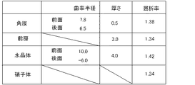
図7は、モデル化された被検眼の屈折要素を表し、91は角膜、92は前房、93は水晶体、94は硝子体、95は虹彩面である。それらの曲率半径、厚さ、屈折率について図8の表に示したモデルを考える。なお、これら屈折要素の屈折率、更には前述した入射角θiと走査角θi’との関係といった被検眼Eの光学的な情報に関するデータは、記憶手段であるメモリ24に記憶される。これらの屈折要素より計算すると、眼の前側主平面は角膜から1.6mmの位置であり、後側主平面は角膜より1.9mmの位置である。ピボットポイントがこの主平面に一致している場合には、スネルの法則が適用でき、
θi’= asin{(sinθi)/Nvit}
である。
ピボットポイントが主平面とは異なる場合には、ピボットポイントと後側主平面の距離δpvとを用いることによりさらに精度の良くθi’を求めることができる。
FIG. 7 shows a modeled refractive element of the eye to be examined, in which 91 is the cornea, 92 is the anterior chamber, 93 is the crystalline lens, 94 is the vitreous body, and 95 is the iris surface. Consider the model shown in the table of FIG. 8 for the radius of curvature, thickness, and refractive index. Note that the data relating to the optical information of the eye E such as the refractive index of these refractive elements and the relationship between the incident angle θi and the scanning angle θi ′ described above is stored in a
θi '= asin {(sinθi) / Nvit}
It is.
When the pivot point is different from the main plane, θi ′ can be obtained with higher accuracy by using the distance δpv between the pivot point and the rear main plane.
眼の焦点距離をfeye、角膜頂点から前側主点までの距離をo1とし、角膜頂点からピボットの結像位置(スキャンミラー共役位置)までの距離をinpv、硝子体の屈折率をNvitとすると、
δpv=(1/feye-1/(o1-ipv))^(-1)×Nvit
である。図8に示した眼モデルを用いて計算するとfeye=17mm,o1=1,8
mmであり、前述したようにオートアライメント後のピボットポイントが虹彩面95と一致する場合には、inpv=3.5でありNvit=1.34とするとδpv=1,8mmになる。
If the focal length of the eye is feee, the distance from the corneal apex to the front principal point is o1, the distance from the corneal apex to the pivot imaging position (scan mirror conjugate position) is inpv, and the refractive index of the vitreous body is Nvit,
δpv = (1 / feye-1 / (o1-ipv)) ^ (-1) × Nvit
It is. When calculated using the eye model shown in FIG. 8, feee = 17 mm, o1 = 1,8.
mm, and when the pivot point after auto-alignment coincides with the
図6において、81は、眼の光学系の後側主点位置を表す。82は、網膜面からみた見かけ上のピボット位置であり、前述の通り後側主点からの距離はδpvである。このピボットポイントの網膜面からの距離をpvlとすると、 pvl=RmxL’-hj’である。CG面上の測定光の到達位置と、被検眼Eの主点81とを結ぶ線分83と、虹彩面85とピボットポイント82を通過する光80とは、光軸(眼軸)が網膜と交わる点を通り該光軸に垂直な面84上で交わる。したがって、被検眼の主点81とピボットポイント82との距離をδpvとすると、角θi’は下記の式で表すことができる。
θi’= atan( (δpv+pvl)×tan(refθi)/pvl)
ここで、refθi= asin(sin(θi)/Nvit)である。
In FIG. 6,
θi '= atan ((δpv + pvl) × tan (refθi) / pvl)
Here, refθi = asin (sin (θi) / Nvit).
このようにして求めたθi’を用いて、正確な網膜の形状を極座標を用いて、
Imagep(θi’, RmxL’-hj’)
のように表すことができる(ステップS905)。
Using θi ′ thus determined, the exact retina shape is obtained using polar coordinates,
Imagep (θi ', RmxL'-hj')
(Step S905).
(実際の形状を表す画像データ)
以上のように計算して求めた、θi’,hj’,RmxL’を用いて直交するx、y座標を用いた実形状を表す画像データは、Image(x,y)と表すことができる。ただし、
x = (RmxL’-hj’)×sin(θi’)
y = RmxL’-{(RmxL’-hj’)×cos(θi’)}
操作者は、表示切り替えスイッチ20fを操作することによりこのように演算した、実形状・実寸法に近い断層画像(ステップS907)、または通常の断層画像(光学的な距離に基づく断層画像)を切り替え表示することができる(ステップS908)。また、網膜の色素上皮にフィッティングする円を求めてこの曲率半径を網膜の曲率半径として表示してもよい。また部分的にフィッティングする円を求めその曲率半径の分布を表示したり、各層の多項式等の近似曲線をもとめその係数を表示してもよい。なお、以上の実際の形状を現す画像データを求める工程は、本発明における、断層画像を、前述した第一の位置とは異なる参照光の光路長に対応する光路長となる測定光の光路上の第二の位置に対応して得られる断層画像に補正する工程に対応する。なお、この第二の位置は、前述した実寸法に近い値からなる。
(Image data representing the actual shape)
The image data representing the actual shape using the x, y coordinates orthogonal to each other using θi ′, hj ′, RmxL ′ obtained by calculation as described above can be expressed as Image (x, y). However,
x = (RmxL'-hj ') × sin (θi')
y = RmxL '-{(RmxL'-hj') × cos (θi ')}
The operator switches the tomographic image close to the actual shape and actual size (step S907) or the normal tomographic image (tomographic image based on the optical distance) calculated in this way by operating the display changeover switch 20f. It can be displayed (step S908). Further, a circle that fits to the pigment epithelium of the retina may be obtained and this radius of curvature may be displayed as the radius of curvature of the retina. Alternatively, a circle to be partially fitted may be obtained and the distribution of the radius of curvature may be displayed, or the coefficients thereof may be displayed by obtaining an approximate curve such as a polynomial of each layer. Note that the step of obtaining the image data representing the actual shape described above includes the step of obtaining the tomographic image on the optical path of the measurement light having an optical path length corresponding to the optical path length of the reference light different from the first position described above. This corresponds to the step of correcting to a tomographic image obtained corresponding to the second position. The second position has a value close to the actual size described above.
すなわち、画像データの演算に際し、測定光が被検眼に入射する入射点(ピボットポイント)から網膜までの距離を、検出された光路長に基づいて求め、当該光路長を用いて演算を実施しても良い。また、被検眼の内部であって該入射点での眼軸と測定光とが成す角度を求め、当該角度に基づいて画像データを演算する様式であっても良い。 That is, when calculating the image data, the distance from the incident point (pivot point) where the measurement light enters the eye to be examined is determined based on the detected optical path length, and the calculation is performed using the optical path length. Also good. Further, it may be a mode in which an angle formed by the eye axis and the measurement light at the incident point inside the eye to be examined is calculated, and image data is calculated based on the angle.
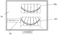
図10に、表示部20上に表示される断層画像の表示例を示す。図10には、表示領域20gに表示された光学的な距離に基づく断層画像と、表示領域20hに表示された本実施形態により求めた実寸法・実形状を示す断層画像が示されている。更に、表示領域20hには、実寸法を示すスケールが表示されている。この実寸法は、RmxL’とθi’から求めることができ、コヒーレンスゲートのθ’=0の位置を基準に表示されている。また、網膜色素上皮にフィッティングする円の曲率半径が表示領域20iに表示されている。なお、切り替え操作に基づき、両断層画像を交互に表示するようにしても良い。
FIG. 10 shows a display example of a tomographic image displayed on the
このように本実施形態によれば、被検眼の光学的な情報(屈折要素の屈折率、入射角に対する走査角の関係等)と光路長とを用いて画像データを求めることにより、実形状に近い被検眼の断層画像を得ることができる。また、光学的な距離に基づく断層画像と本実施形態で得られた断層画像とを比較表示することができる。 As described above, according to the present embodiment, the actual shape is obtained by obtaining the image data using the optical information of the eye to be examined (the refractive index of the refractive element, the relationship of the scanning angle with respect to the incident angle, etc.) and the optical path length. A tomographic image of a close eye to be examined can be obtained. Further, the tomographic image based on the optical distance and the tomographic image obtained in the present embodiment can be compared and displayed.
なお、本実施形態では、被検眼の光学的な情報として、屈折要素の屈折率、及び入射角と走査角との関係の両者を予め記憶する場合を例示した。しかし、本発明は当該形態に限定されず、少なくともこれらの何れか一方を記憶することとし、且つ他方を前述した演算等による求める形態とし、メモリの容量を抑える態様としても良い。 In the present embodiment, the case where both the refractive index of the refractive element and the relationship between the incident angle and the scanning angle are stored in advance as optical information of the eye to be examined has been illustrated. However, the present invention is not limited to this form, and at least one of these may be stored, and the other may be obtained by the above-described calculation or the like, and the memory capacity may be reduced.
[第2の実施形態]
(三次元形状)
第1の実施形態においては、眼底の1ラインを走査し断層画像を表示するBスキャン画像について、実寸法の画像データを求める方法を示したが、眼底面を2次元的にスキャンして3次元データを得る3D画像データを実寸法データに変換してもよい。
[Second Embodiment]
(Three-dimensional shape)
In the first embodiment, a method for obtaining actual size image data for a B-scan image that scans one line of the fundus and displays a tomographic image has been described. The 3D image data from which data is obtained may be converted into actual size data.
ただし、通常OCT装置は、X、Y二つのスキャンミラーを近接して配置するタンデムスキャン方式により、2次元スキャンを行う。この方式の場合、ピボットポイントが、XスキャンとYスキャンで異なる。これらのピボットポイントの位置は、設計値より求めてもよい。また前述と同様の方法で、Yスキャンミラーのみを往復走査し光線の像が動かなくなる位置(Yスキャンミラーのピボットポイント)に反射部材を配置し、この位置と光路長が等しくなる参照ミラー位置Rmoyを干渉信号より求め同様の計算を行う。三次元スキャンした結果は、Xスキャンミラーの走査角をθxi、Yスキャンミラーの走査角をθyj、コヒーレンスゲートからの距離をhkとして、 Image(θxi,θyj,hk)とあらわすことができる。 However, the normal OCT apparatus performs two-dimensional scanning by a tandem scanning method in which two X and Y scanning mirrors are arranged close to each other. In this method, the pivot point is different between the X scan and the Y scan. The positions of these pivot points may be obtained from design values. Further, in the same manner as described above, a reflection member is arranged at a position where the light beam image does not move by reciprocally scanning only the Y scan mirror (the pivot point of the Y scan mirror), and the reference mirror position Rmoy where the optical path length is equal to this position. Is obtained from the interference signal and the same calculation is performed. The result of the three-dimensional scanning can be expressed as Image (θxi, θyj, hk), where the scanning angle of the X scan mirror is θxi, the scanning angle of the Y scan mirror is θyj, and the distance from the coherence gate is hk.
前述と同様、この画像データを取得した際の参照ミラー位置、Rmx1を用いて、直交するx、y、z軸を用いた実寸法の画像データは、下記のように表すことができる。
x = (RmxL’-hk’)×cos(θyj’)×sin(θxi’)
y = (RmyL’-hk)×cos(θxi’)×sin(θyj’)
z = RmxL’-(RmxL’-hk’)×cos(θxi’)×cos(θyj’)
As described above, the actual size image data using the x, y, and z axes orthogonal to each other using the reference mirror position Rmx1 when the image data is acquired can be expressed as follows.
x = (RmxL'-hk ') × cos (θyj') × sin (θxi ')
y = (RmyL'-hk) × cos (θxi ') × sin (θyj')
z = RmxL '-(RmxL'-hk') × cos (θxi ') × cos (θyj')
このように参照ミラー位置を検知し、スキャンミラー角度、コヒーレンスゲートからの距離に関する光強度のデータより、実寸法による眼底形状のデータを作成することができる(RmyL’は、RmxL’と同様にYスキャンミラーによるピボットポイントからの光学的距離RmyLから求めた被検眼内の実距離である)。前記と同様、このデータをもとに、実寸法で眼底像を表示しても良いし、各部の曲率半径を演算し表示しても良い。
本実施形態によれば、更に、被検眼の3次元画像データを得ることができる。
In this way, the position of the reference mirror is detected, and the fundus shape data based on the actual dimensions can be generated from the light intensity data relating to the scan mirror angle and the distance from the coherence gate (RmyL ′ is Y in the same manner as RmxL ′). This is the actual distance in the eye to be examined determined from the optical distance RmyL from the pivot point by the scan mirror). Similarly to the above, based on this data, the fundus image may be displayed in actual dimensions, or the radius of curvature of each part may be calculated and displayed.
According to the present embodiment, three-dimensional image data of the eye to be examined can be further obtained.
[第3の実施形態]
第1、第2の実施形態において、眼の光学要素をモデル化して演算をおこなったが、この定数は、文献により多少異なる値が記載されている。したがって、図8のような表をモニター上に表示し、マウス、キーボード等の入力部である入力手段により、使用者が被検眼の屈折要素の屈折率等のデータの値を、自由に入力することを可能にしてもよい。また、あらかじめ複数の定数をメモリー24に記憶しておき、被検者のマウス操作に応じて、プルダウン等により、これらの値を選択可能にすることによりさらに使い勝手を向上することができる。これら複数の定数の中に、無水晶体眼の定数、IOL被検眼の定数を含めるとさらに使い勝手が良い。
[Third Embodiment]
In the first and second embodiments, the calculation was performed by modeling the optical element of the eye, but this constant has a slightly different value depending on the literature. Therefore, a table as shown in FIG. 8 is displayed on the monitor, and the user freely inputs data values such as the refractive index of the refractive element of the eye to be examined by an input means such as an input unit such as a mouse or a keyboard. May be possible. Further, it is possible to further improve the usability by storing a plurality of constants in the
また、例えば、角膜形状測定、屈折計、眼軸長測定装置により求めた測定値により求めた被検眼の角膜の曲率半径、屈折力、眼軸長のデータを入力可能にすることにより、さらに正確な形状を求めることができる。制御部は、入力された測定値より、屈折要素の曲率半径・厚さを演算により求め、このデータに基づいて前記θ’を演算する。
本実施形態によれば、被検眼毎に入力値を入力・変更することができるので、より被検眼の形状に近い画像データを得ることができる。
In addition, for example, by making it possible to input data on the curvature radius, refractive power, and axial length of the cornea of the eye to be examined, which is obtained from the measured values obtained from the corneal shape measurement, refractometer, and axial length measuring device A simple shape. The control unit obtains the radius of curvature / thickness of the refractive element from the input measured value, and computes θ ′ based on this data.
According to this embodiment, the input value can be input and changed for each eye to be examined, so that image data closer to the shape of the eye to be examined can be obtained.
(その他の実施例)
また、本発明は、以下の処理を実行することによっても実現される。即ち、上述した実施形態の機能を実現するソフトウェア(プログラム)を、ネットワーク又は各種記憶媒体を介してシステム或いは装置に供給し、そのシステム或いは装置のコンピュータ(またはCPUやMPU等)がプログラムを読み出して実行する処理である。
(Other examples)
The present invention can also be realized by executing the following processing. That is, software (program) that realizes the functions of the above-described embodiments is supplied to a system or apparatus via a network or various storage media, and a computer (or CPU, MPU, or the like) of the system or apparatus reads the program. It is a process to be executed.
なお、上述した実施形態では、被検査物として被検眼を、被検査領域として網膜を用いた場合を例示しているが、本発明はこれに限定されず、内部に屈折要素を包含する被検査物の内に存在する被検査領域の断層画像を撮像する種々の場合に適用可能である。 In the above-described embodiment, the case where the eye to be inspected is used as the object to be inspected and the retina is used as the area to be inspected is illustrated, but the present invention is not limited to this, and the object to be inspected includes a refractive element inside. The present invention can be applied to various cases where a tomographic image of a region to be inspected existing in an object is captured.
1 光源
2 導光部
3 光分岐部
4 導光部
5 レンズ
6 走査部
7 レンズ
8 分岐ミラー
9 対物レンズ
10 導光部
11 レンズ
12 参照ミラー
13 ステージ
14 導光部
15 レンズ
16 分光部
17 レンズ
18 撮像部
19 制御部
20 表示部
21 前眼部照明光源
22 レンズ
23 前眼部撮像部
DESCRIPTION OF SYMBOLS 1 Light source 2 Light guide
Claims (8)
前記光源からの光を、参照光と測定光とに分岐するための光分岐手段、
前記参照光の光路長を調整する調整手段、
前記測定光を被検査物に照射することにより得られる戻り光と前記参照光との合波光を分光して前記合波光から干渉信号を取得する分光手段、
前記被検査物の断層画像の撮像を行う際の前記光路長を検出する検出手段、
前記被検査物の光学的な情報に関するデータを記憶する記憶手段、及び
前記光路長及び前記被検査物の光学的な情報に関するデータを用いて、前記分光手段で取得した前記干渉信号から画像データを演算する演算手段、を有することを特徴とする断層画像撮像装置。 A light source for generating light;
A light branching means for branching light from the light source into reference light and measurement light;
Adjusting means for adjusting the optical path length of the reference light;
A spectroscopic unit that obtains an interference signal from the combined light by splitting the combined light of the return light and the reference light obtained by irradiating the object to be inspected with the measurement light;
Detecting means for detecting the optical path length when taking a tomographic image of the inspection object;
Image data is obtained from the interference signal acquired by the spectroscopic means, using storage means for storing data relating to optical information of the inspection object, and data relating to the optical path length and optical information of the inspection object. A tomographic imaging apparatus characterized by comprising a computing means for computing.
前記屈折要素の屈折率の値を入力する手段を更に有し、
前記演算手段が、前記入力手段で入力された値にもとづいて、前記被検査領域の形状を演算することを特徴とする請求項1に記載の断層画像撮像装置。 The optical information of the inspection object is a refractive index of a refractive element of the inspection object,
Means for inputting a value of a refractive index of the refractive element;
The tomographic imaging apparatus according to claim 1, wherein the calculation unit calculates the shape of the region to be inspected based on a value input by the input unit.
前記検出手段は、前記調整手段の移動距離に基づいて前記光路長を検出することを特徴とする請求項1乃至4のいずれから1項に記載の断層撮像装置。 The adjusting means adjusts the optical path length by moving along the optical axis of the reference light,
5. The tomographic imaging apparatus according to claim 1, wherein the detecting unit detects the optical path length based on a moving distance of the adjusting unit.
から前記被検査領域までの距離を、前記光路長から求めて前記画像データを演算することを特徴とする請求項1乃至5のいずれから1項に記載の断層撮像装置。 6. The calculation unit according to claim 1, wherein the calculation unit calculates the image data by obtaining a distance from an incident point where the measurement light enters the inspection object to the inspection area from the optical path length. The tomographic imaging apparatus according to any one of items 1 to 3.
前記断層画像を取得する際の、前記参照光の光路長に対応する光路長となる前記測定光の光路上の第一の位置を取得する工程と、
前記断層画像を、前記第一の位置とは異なる前記参照光の光路長に対応する光路長となる前記測定光の光路上の第二の位置に対応して得られる断層画像に補正する工程と、
を有することを特徴とする光断層画像撮像方法。 An optical tomographic imaging method for acquiring a tomographic image of the subject eye based on a combined light obtained by combining a return light from the subject eye irradiated with the measurement light and a reference light corresponding to the measurement light,
Obtaining a first position on the optical path of the measurement light, which is an optical path length corresponding to the optical path length of the reference light, when acquiring the tomographic image;
Correcting the tomographic image into a tomographic image obtained corresponding to a second position on the optical path of the measurement light having an optical path length corresponding to an optical path length of the reference light different from the first position; ,
An optical tomographic imaging method characterized by comprising:
Priority Applications (2)
| Application Number | Priority Date | Filing Date | Title |
|---|---|---|---|
| JP2011010150A JP5794664B2 (en) | 2011-01-20 | 2011-01-20 | Tomographic image generating apparatus and tomographic image generating method |
| US13/282,778 US9149181B2 (en) | 2011-01-20 | 2011-10-27 | Tomographic imaging apparatus and photographing method |
Applications Claiming Priority (1)
| Application Number | Priority Date | Filing Date | Title |
|---|---|---|---|
| JP2011010150A JP5794664B2 (en) | 2011-01-20 | 2011-01-20 | Tomographic image generating apparatus and tomographic image generating method |
Publications (3)
| Publication Number | Publication Date |
|---|---|
| JP2012148003A true JP2012148003A (en) | 2012-08-09 |
| JP2012148003A5 JP2012148003A5 (en) | 2014-03-06 |
| JP5794664B2 JP5794664B2 (en) | 2015-10-14 |
Family
ID=46544197
Family Applications (1)
| Application Number | Title | Priority Date | Filing Date |
|---|---|---|---|
| JP2011010150A Active JP5794664B2 (en) | 2011-01-20 | 2011-01-20 | Tomographic image generating apparatus and tomographic image generating method |
Country Status (2)
| Country | Link |
|---|---|
| US (1) | US9149181B2 (en) |
| JP (1) | JP5794664B2 (en) |
Cited By (12)
| Publication number | Priority date | Publication date | Assignee | Title |
|---|---|---|---|---|
| JP2016158906A (en) * | 2015-03-02 | 2016-09-05 | 株式会社ニデック | Eye axial length measurement device, eye ball shape information acquisition method, and eye ball shape information acquisition program |
| KR20170008172A (en) * | 2015-07-13 | 2017-01-23 | 캐논 가부시끼가이샤 | Image processing apparatus, image processing method, and optical coherence tomography apparatus |
| JP2018149449A (en) * | 2018-07-10 | 2018-09-27 | 株式会社トプコン | Ophthalmic photographing apparatus and ophthalmic information processing apparatus |
| WO2019151301A1 (en) * | 2018-01-31 | 2019-08-08 | 株式会社Screenホールディングス | Image processing method, program, and recording medium |
| JP2019195636A (en) * | 2018-05-11 | 2019-11-14 | オプトス ピーエルシー | Oct retina image data rendering method, storage medium that stores oct retina image data rendering program, oct retina image data rendering program, and oct retina image data rendering device |
| US10537243B2 (en) | 2017-04-10 | 2020-01-21 | Canon Kabushiki Kaisha | Image generating apparatus, image generating method, and computer-readable medium |
| JP2020048695A (en) * | 2018-09-25 | 2020-04-02 | 株式会社トプコン | Ophthalmologic information processing apparatus, ophthalmologic apparatus, and ophthalmologic information processing method |
| CN111163684A (en) * | 2017-08-14 | 2020-05-15 | 奥普托斯股份有限公司 | Ophthalmologic apparatus |
| JP2020151094A (en) * | 2019-03-19 | 2020-09-24 | 株式会社トプコン | Ophthalmologic apparatus |
| JP7289394B2 (en) | 2019-01-28 | 2023-06-09 | 株式会社トプコン | Ophthalmic information processing device, ophthalmic device, ophthalmic information processing method, and program |
| JP7306978B2 (en) | 2019-01-16 | 2023-07-11 | 株式会社トプコン | Ophthalmic information processing device, ophthalmic device, ophthalmic information processing method, and program |
| US11717150B2 (en) | 2018-03-16 | 2023-08-08 | Topcon Corporation | Ophthalmologic apparatus, and ophthalmologic information processing apparatus |
Families Citing this family (21)
| Publication number | Priority date | Publication date | Assignee | Title |
|---|---|---|---|---|
| JP2012042348A (en) | 2010-08-19 | 2012-03-01 | Canon Inc | Tomographic image display device and control method therefor |
| JP5794664B2 (en) * | 2011-01-20 | 2015-10-14 | キヤノン株式会社 | Tomographic image generating apparatus and tomographic image generating method |
| WO2014085911A1 (en) | 2012-12-05 | 2014-06-12 | Tornado Medical Systems, Inc. | System and method for wide field oct imaging |
| JP6147001B2 (en) * | 2012-12-28 | 2017-06-14 | キヤノン株式会社 | Image processing apparatus and image processing method |
| US9558552B2 (en) * | 2013-02-22 | 2017-01-31 | Sony Corporation | Eye-fundus image optimization output device and method, and computer readable medium |
| JP6482171B2 (en) | 2014-01-10 | 2019-03-13 | キヤノン株式会社 | Polarized OCT device |
| JP2015197538A (en) * | 2014-03-31 | 2015-11-09 | 株式会社ニデック | Display unit-mounting attachment, and display device |
| JP6468764B2 (en) | 2014-09-08 | 2019-02-13 | キヤノン株式会社 | Ophthalmic equipment |
| JP6685701B2 (en) | 2014-12-26 | 2020-04-22 | キヤノン株式会社 | Surface emitting laser, information acquisition device, imaging device, laser array, and method for manufacturing surface emitting laser |
| JP6576092B2 (en) * | 2015-04-30 | 2019-09-18 | キヤノン株式会社 | Surface emitting laser, information acquisition device, and imaging device |
| JP6767762B2 (en) * | 2016-03-29 | 2020-10-14 | キヤノン株式会社 | Information processing device, control method of information processing device, and execution program of the control method |
| AU2017383451B2 (en) * | 2016-12-20 | 2023-02-02 | Alcon Inc. | Systems and methods for wide field-of-view optical coherence tomography |
| JP6929684B2 (en) | 2017-04-06 | 2021-09-01 | キヤノン株式会社 | Ophthalmologic imaging device and its control method |
| EP3655748B1 (en) | 2017-07-18 | 2023-08-09 | Perimeter Medical Imaging, Inc. | Sample container for stabilizing and aligning excised biological tissue samples for ex vivo analysis |
| JP2019037650A (en) * | 2017-08-28 | 2019-03-14 | キヤノン株式会社 | Image acquisition device and control method of the same |
| JP2019058491A (en) * | 2017-09-27 | 2019-04-18 | 株式会社トプコン | Ophthalmological device |
| WO2019074077A1 (en) * | 2017-10-13 | 2019-04-18 | 株式会社ニコン | Ophthalmology system, image signal output method, image signal output device, program, and three-dimensional oculus fundi image generation method |
| US11439301B2 (en) | 2019-01-16 | 2022-09-13 | Topcon Corporation | Ophthalmologic information processing apparatus, ophthalmologic apparatus and ophthalmologic information processing method |
| US11141060B2 (en) | 2019-01-16 | 2021-10-12 | Topcon Corporation | Ophthalmologic apparatus and method of controlling the same |
| JP7297302B2 (en) | 2019-08-30 | 2023-06-26 | 株式会社トーメーコーポレーション | ophthalmic equipment |
| US20230346217A1 (en) * | 2022-04-28 | 2023-11-02 | Alcon Inc. | Reducing abberations in ophthalmic imaging |
Citations (5)
| Publication number | Priority date | Publication date | Assignee | Title |
|---|---|---|---|---|
| JP2002515593A (en) * | 1998-05-15 | 2002-05-28 | レーザー・ディアグノスティック・テクノロジーズ・インコーポレイテッド | Method and apparatus for recording three-dimensional distribution of scattered light |
| JP2007101268A (en) * | 2005-09-30 | 2007-04-19 | Fujifilm Corp | Optical tomographic imaging device |
| JP2008298767A (en) * | 2007-05-02 | 2008-12-11 | Canon Inc | Image forming method using optical interference tomograph meter, and optical interference tomogram |
| JP2009244232A (en) * | 2008-03-31 | 2009-10-22 | Fujifilm Corp | Optical tomographic image forming method and optical tomographic imaging apparatus |
| JP2010000191A (en) * | 2008-06-19 | 2010-01-07 | Topcon Corp | Optical image measuring instrument |
Family Cites Families (60)
| Publication number | Priority date | Publication date | Assignee | Title |
|---|---|---|---|---|
| US4820037A (en) * | 1985-01-10 | 1989-04-11 | Canon Kabushiki Kaisha | Apparatus for measuring the refractive power of an eye |
| JPS61234837A (en) * | 1985-04-12 | 1986-10-20 | キヤノン株式会社 | Apparatus for measuring eye refraction |
| JPS62122629A (en) * | 1985-11-25 | 1987-06-03 | キヤノン株式会社 | Eye refractometer |
| JPH0381879A (en) * | 1989-08-24 | 1991-04-08 | Canon Inc | Medical image processor |
| EP0581871B2 (en) * | 1991-04-29 | 2009-08-12 | Massachusetts Institute Of Technology | Apparatus for optical imaging and measurement |
| US6619799B1 (en) * | 1999-07-02 | 2003-09-16 | E-Vision, Llc | Optical lens system with electro-active lens having alterably different focal lengths |
| US6293674B1 (en) * | 2000-07-11 | 2001-09-25 | Carl Zeiss, Inc. | Method and apparatus for diagnosing and monitoring eye disease |
| US6296358B1 (en) * | 2000-07-14 | 2001-10-02 | Visual Pathways, Inc. | Ocular fundus auto imager |
| JP2003126043A (en) * | 2001-10-22 | 2003-05-07 | Canon Inc | Ophthalmologic photographic apparatus |
| US7365858B2 (en) * | 2001-12-18 | 2008-04-29 | Massachusetts Institute Of Technology | Systems and methods for phase measurements |
| US7557929B2 (en) * | 2001-12-18 | 2009-07-07 | Massachusetts Institute Of Technology | Systems and methods for phase measurements |
| US7113818B2 (en) * | 2002-04-08 | 2006-09-26 | Oti Ophthalmic Technologies Inc. | Apparatus for high resolution imaging of moving organs |
| US7136518B2 (en) * | 2003-04-18 | 2006-11-14 | Medispectra, Inc. | Methods and apparatus for displaying diagnostic data |
| US7198777B2 (en) * | 2003-06-17 | 2007-04-03 | The Board Of Trustees Of The University Of Illinois | Optical contrast agents for optically modifying incident radiation |
| JP4503354B2 (en) * | 2004-05-31 | 2010-07-14 | 株式会社トプコン | Optometry equipment |
| JP2005351839A (en) * | 2004-06-14 | 2005-12-22 | Fujinon Corp | Tomographic imaging equipment |
| JP2006122649A (en) * | 2004-09-30 | 2006-05-18 | Nidek Co Ltd | Method for measurement of object and ophthalmic apparatus using the method |
| JP4566685B2 (en) * | 2004-10-13 | 2010-10-20 | 株式会社トプコン | Optical image measuring device and optical image measuring method |
| US7850305B2 (en) * | 2004-12-03 | 2010-12-14 | Topcon Corporation | Apparatus and method for measuring spectrum image data of eyeground |
| WO2006078718A1 (en) * | 2005-01-20 | 2006-07-27 | Zygo Corporation | Interferometer for determining characteristics of an object surface |
| US7884945B2 (en) * | 2005-01-21 | 2011-02-08 | Massachusetts Institute Of Technology | Methods and apparatus for optical coherence tomography scanning |
| JP4916779B2 (en) * | 2005-09-29 | 2012-04-18 | 株式会社トプコン | Fundus observation device |
| JP2007101250A (en) * | 2005-09-30 | 2007-04-19 | Fujifilm Corp | Optical tomographic imaging method |
| US7400410B2 (en) * | 2005-10-05 | 2008-07-15 | Carl Zeiss Meditec, Inc. | Optical coherence tomography for eye-length measurement |
| JP4850495B2 (en) * | 2005-10-12 | 2012-01-11 | 株式会社トプコン | Fundus observation apparatus and fundus observation program |
| JP4884777B2 (en) * | 2006-01-11 | 2012-02-29 | 株式会社トプコン | Fundus observation device |
| TWI292030B (en) * | 2006-01-13 | 2008-01-01 | Ind Tech Res Inst | High density multi-channel detecting device |
| JP4869757B2 (en) * | 2006-03-24 | 2012-02-08 | 株式会社トプコン | Fundus observation device |
| TW200739033A (en) * | 2006-04-07 | 2007-10-16 | Chien Chou | Cross-sectional scanning method using optical image and the apparatus thereof |
| JP4864515B2 (en) * | 2006-04-07 | 2012-02-01 | 株式会社トプコン | Fundus observation device |
| JP4969925B2 (en) * | 2006-06-28 | 2012-07-04 | 株式会社トプコン | Fundus observation device |
| CN101112316A (en) * | 2006-07-28 | 2008-01-30 | Ge医疗系统环球技术有限公司 | X-radial mixed diagnosis system |
| JP5085086B2 (en) * | 2006-10-04 | 2012-11-28 | 株式会社トプコン | Fundus observation apparatus, fundus image display apparatus, and program |
| JP5007114B2 (en) * | 2006-12-22 | 2012-08-22 | 株式会社トプコン | Fundus observation apparatus, fundus image display apparatus, and program |
| JP4921201B2 (en) * | 2007-02-23 | 2012-04-25 | 株式会社トプコン | Optical image measurement device and program for controlling optical image measurement device |
| JP5061380B2 (en) * | 2007-03-23 | 2012-10-31 | 株式会社トプコン | Fundus observation apparatus, ophthalmologic image display apparatus, and program |
| JP5138977B2 (en) * | 2007-05-24 | 2013-02-06 | 株式会社トプコン | Optical image measuring device |
| JP4940070B2 (en) * | 2007-09-10 | 2012-05-30 | 国立大学法人 東京大学 | Fundus observation apparatus, ophthalmic image processing apparatus, and program |
| JP4940069B2 (en) * | 2007-09-10 | 2012-05-30 | 国立大学法人 東京大学 | Fundus observation apparatus, fundus image processing apparatus, and program |
| US7878651B2 (en) * | 2007-12-26 | 2011-02-01 | Carl Zeiss Meditec, Inc. | Refractive prescription using optical coherence tomography |
| JP2009207590A (en) * | 2008-03-03 | 2009-09-17 | Topcon Corp | Stereomicroscope |
| US8125645B2 (en) * | 2008-03-31 | 2012-02-28 | Fujifilm Corporation | Optical tomographic imaging system, tomographic image acquiring method, and optical tomographic image forming method |
| US8718743B2 (en) * | 2008-04-24 | 2014-05-06 | Duke University | Methods for single-pass volumetric bidirectional blood flow imaging spectral domain optical coherence tomography using a modified hilbert transform |
| JP5306041B2 (en) * | 2008-05-08 | 2013-10-02 | キヤノン株式会社 | Imaging apparatus and method thereof |
| JP5340636B2 (en) * | 2008-05-19 | 2013-11-13 | 株式会社トプコン | Fundus observation device |
| JP5331395B2 (en) * | 2008-07-04 | 2013-10-30 | 株式会社ニデック | Optical tomography system |
| JP5306075B2 (en) * | 2008-07-07 | 2013-10-02 | キヤノン株式会社 | Imaging apparatus and imaging method using optical coherence tomography |
| US8004688B2 (en) * | 2008-11-26 | 2011-08-23 | Zygo Corporation | Scan error correction in low coherence scanning interferometry |
| JP4850892B2 (en) * | 2008-12-19 | 2012-01-11 | キヤノン株式会社 | Fundus image display apparatus, control method therefor, and computer program |
| JP5275880B2 (en) * | 2009-04-03 | 2013-08-28 | 株式会社トプコン | Optical image measuring device |
| US8366271B2 (en) * | 2010-01-20 | 2013-02-05 | Duke University | Systems and methods for surgical microscope and optical coherence tomography (OCT) imaging |
| EP2552297A1 (en) * | 2010-03-31 | 2013-02-06 | Canon Kabushiki Kaisha | Optical coherence tomographic imaging apparatus and control apparatus therefor |
| JP2011257160A (en) * | 2010-06-04 | 2011-12-22 | Canon Inc | Optical interference tomographic imaging device, optical interference tomographic imaging method, and program |
| JP2012042348A (en) | 2010-08-19 | 2012-03-01 | Canon Inc | Tomographic image display device and control method therefor |
| JP5762712B2 (en) * | 2010-09-30 | 2015-08-12 | 株式会社ニデック | Ophthalmic observation system |
| JP5733960B2 (en) | 2010-11-26 | 2015-06-10 | キヤノン株式会社 | Imaging method and imaging apparatus |
| JP5794664B2 (en) * | 2011-01-20 | 2015-10-14 | キヤノン株式会社 | Tomographic image generating apparatus and tomographic image generating method |
| US8517537B2 (en) * | 2011-01-20 | 2013-08-27 | Canon Kabushiki Kaisha | Optical coherence tomographic imaging method and optical coherence tomographic imaging apparatus |
| US9161690B2 (en) * | 2011-03-10 | 2015-10-20 | Canon Kabushiki Kaisha | Ophthalmologic apparatus and control method of the same |
| JP2013031634A (en) * | 2011-06-30 | 2013-02-14 | Canon Inc | Imaging apparatus |
-
2011
- 2011-01-20 JP JP2011010150A patent/JP5794664B2/en active Active
- 2011-10-27 US US13/282,778 patent/US9149181B2/en active Active
Patent Citations (5)
| Publication number | Priority date | Publication date | Assignee | Title |
|---|---|---|---|---|
| JP2002515593A (en) * | 1998-05-15 | 2002-05-28 | レーザー・ディアグノスティック・テクノロジーズ・インコーポレイテッド | Method and apparatus for recording three-dimensional distribution of scattered light |
| JP2007101268A (en) * | 2005-09-30 | 2007-04-19 | Fujifilm Corp | Optical tomographic imaging device |
| JP2008298767A (en) * | 2007-05-02 | 2008-12-11 | Canon Inc | Image forming method using optical interference tomograph meter, and optical interference tomogram |
| JP2009244232A (en) * | 2008-03-31 | 2009-10-22 | Fujifilm Corp | Optical tomographic image forming method and optical tomographic imaging apparatus |
| JP2010000191A (en) * | 2008-06-19 | 2010-01-07 | Topcon Corp | Optical image measuring instrument |
Cited By (27)
| Publication number | Priority date | Publication date | Assignee | Title |
|---|---|---|---|---|
| JP2016158906A (en) * | 2015-03-02 | 2016-09-05 | 株式会社ニデック | Eye axial length measurement device, eye ball shape information acquisition method, and eye ball shape information acquisition program |
| KR20170008172A (en) * | 2015-07-13 | 2017-01-23 | 캐논 가부시끼가이샤 | Image processing apparatus, image processing method, and optical coherence tomography apparatus |
| JP2017018435A (en) * | 2015-07-13 | 2017-01-26 | キヤノン株式会社 | Image processing device, image processing method and light interference tomographic imaging device |
| US10299675B2 (en) | 2015-07-13 | 2019-05-28 | Canon Kabushiki Kaisha | Image processing apparatus, image processing method, and optical coherence tomography apparatus |
| KR102049242B1 (en) * | 2015-07-13 | 2019-11-28 | 캐논 가부시끼가이샤 | Image processing apparatus, image processing method, and optical coherence tomography apparatus |
| US10537243B2 (en) | 2017-04-10 | 2020-01-21 | Canon Kabushiki Kaisha | Image generating apparatus, image generating method, and computer-readable medium |
| CN111163684A (en) * | 2017-08-14 | 2020-05-15 | 奥普托斯股份有限公司 | Ophthalmologic apparatus |
| JP7395803B2 (en) | 2017-08-14 | 2023-12-12 | オプトス ピーエルシー | ophthalmology equipment |
| US11617509B2 (en) | 2017-08-14 | 2023-04-04 | Optos Plc | Ophthalmic device |
| CN111163684B (en) * | 2017-08-14 | 2022-07-22 | 奥普托斯股份有限公司 | Ophthalmologic apparatus |
| JP2020530368A (en) * | 2017-08-14 | 2020-10-22 | オプトス ピーエルシー | Ophthalmic equipment |
| JP2019132710A (en) * | 2018-01-31 | 2019-08-08 | 株式会社Screenホールディングス | Image processing method, program, and recording medium |
| WO2019151301A1 (en) * | 2018-01-31 | 2019-08-08 | 株式会社Screenホールディングス | Image processing method, program, and recording medium |
| US11900509B2 (en) | 2018-01-31 | 2024-02-13 | SCREEN Holdings Co., Ltd. | Image processing method for a computer to assist a user in assessment of a cultured embryo |
| US11717150B2 (en) | 2018-03-16 | 2023-08-08 | Topcon Corporation | Ophthalmologic apparatus, and ophthalmologic information processing apparatus |
| JP7368581B2 (en) | 2018-03-16 | 2023-10-24 | 株式会社トプコン | Ophthalmology equipment and ophthalmology information processing equipment |
| US11806077B2 (en) | 2018-03-16 | 2023-11-07 | Topcon Corporation | Ophthalmologic apparatus, and ophthalmologic information processing apparatus |
| JP2022033344A (en) * | 2018-05-11 | 2022-02-28 | オプトス ピーエルシー | Oct retina image data rendering method and oct retina image data rendering device |
| JP2019195636A (en) * | 2018-05-11 | 2019-11-14 | オプトス ピーエルシー | Oct retina image data rendering method, storage medium that stores oct retina image data rendering program, oct retina image data rendering program, and oct retina image data rendering device |
| JP7251028B2 (en) | 2018-05-11 | 2023-04-04 | オプトス ピーエルシー | OCT retinal image data rendering method and OCT retinal image data rendering device |
| US10929963B2 (en) | 2018-05-11 | 2021-02-23 | Optos Plc | OCT image processing |
| JP2018149449A (en) * | 2018-07-10 | 2018-09-27 | 株式会社トプコン | Ophthalmic photographing apparatus and ophthalmic information processing apparatus |
| JP2020048695A (en) * | 2018-09-25 | 2020-04-02 | 株式会社トプコン | Ophthalmologic information processing apparatus, ophthalmologic apparatus, and ophthalmologic information processing method |
| JP7306978B2 (en) | 2019-01-16 | 2023-07-11 | 株式会社トプコン | Ophthalmic information processing device, ophthalmic device, ophthalmic information processing method, and program |
| JP7289394B2 (en) | 2019-01-28 | 2023-06-09 | 株式会社トプコン | Ophthalmic information processing device, ophthalmic device, ophthalmic information processing method, and program |
| JP2020151094A (en) * | 2019-03-19 | 2020-09-24 | 株式会社トプコン | Ophthalmologic apparatus |
| JP7349807B2 (en) | 2019-03-19 | 2023-09-25 | 株式会社トプコン | ophthalmology equipment |
Also Published As
| Publication number | Publication date |
|---|---|
| JP5794664B2 (en) | 2015-10-14 |
| US20120189184A1 (en) | 2012-07-26 |
| US9149181B2 (en) | 2015-10-06 |
Similar Documents
| Publication | Publication Date | Title |
|---|---|---|
| JP5794664B2 (en) | Tomographic image generating apparatus and tomographic image generating method | |
| JP5601613B2 (en) | Fundus photographing device | |
| JP5483873B2 (en) | Optical tomographic imaging apparatus and optical tomographic imaging method | |
| JP6805539B2 (en) | Ophthalmic imaging device | |
| JP5970682B2 (en) | Eyeball measuring device and eyeball measuring method | |
| JP6987522B2 (en) | Image generator, image generation method, and program | |
| US20160157713A1 (en) | Optical coherence tomographic apparatus | |
| JP5913424B2 (en) | Method and analyzer for eye examination | |
| JP2012236006A (en) | Ophthalmic apparatus, method of controlling ophthalmic apparatus, and program | |
| US10918277B2 (en) | Ophthalmic device | |
| JP6221516B2 (en) | Ophthalmic photographing apparatus and ophthalmic photographing program | |
| JP2016067551A (en) | Ophthalmologic apparatus | |
| CN110325101B (en) | Method and device for high-resolution topographic mapping of the cornea of an eye | |
| JP7027698B2 (en) | Ophthalmologic photography equipment | |
| JP2022176282A (en) | Ophthalmologic apparatus and control method thereof | |
| JP2022189969A (en) | Ophthalmologic apparatus, and ophthalmologic information processing system | |
| JP6929684B2 (en) | Ophthalmologic imaging device and its control method | |
| JP6898716B2 (en) | Optical tomography imaging device | |
| JP2020195883A (en) | Ophthalmologic inspection device | |
| JP2020130266A (en) | Ophthalmologic apparatus | |
| JP2019051369A (en) | Ophthalmologic apparatus | |
| WO2022186115A1 (en) | Oct device, and ophthalmic image processing program | |
| JP2018201742A (en) | Ophthalmologic imaging apparatus | |
| JP2019072027A (en) | Ophthalmologic apparatus and focus unit | |
| JP7030577B2 (en) | Ophthalmic equipment |
Legal Events
| Date | Code | Title | Description |
|---|---|---|---|
| RD05 | Notification of revocation of power of attorney |
Free format text: JAPANESE INTERMEDIATE CODE: A7425 Effective date: 20120730 |
|
| RD05 | Notification of revocation of power of attorney |
Free format text: JAPANESE INTERMEDIATE CODE: A7425 Effective date: 20120731 |
|
| RD03 | Notification of appointment of power of attorney |
Free format text: JAPANESE INTERMEDIATE CODE: A7423 Effective date: 20120831 |
|
| RD05 | Notification of revocation of power of attorney |
Free format text: JAPANESE INTERMEDIATE CODE: A7425 Effective date: 20130701 |
|
| A521 | Written amendment |
Free format text: JAPANESE INTERMEDIATE CODE: A523 Effective date: 20140120 |
|
| A621 | Written request for application examination |
Free format text: JAPANESE INTERMEDIATE CODE: A621 Effective date: 20140120 |
|
| A977 | Report on retrieval |
Free format text: JAPANESE INTERMEDIATE CODE: A971007 Effective date: 20141128 |
|
| A131 | Notification of reasons for refusal |
Free format text: JAPANESE INTERMEDIATE CODE: A131 Effective date: 20141222 |
|
| A521 | Written amendment |
Free format text: JAPANESE INTERMEDIATE CODE: A523 Effective date: 20150218 |
|
| TRDD | Decision of grant or rejection written | ||
| A01 | Written decision to grant a patent or to grant a registration (utility model) |
Free format text: JAPANESE INTERMEDIATE CODE: A01 Effective date: 20150714 |
|
| A61 | First payment of annual fees (during grant procedure) |
Free format text: JAPANESE INTERMEDIATE CODE: A61 Effective date: 20150807 |
|
| R151 | Written notification of patent or utility model registration |
Ref document number: 5794664 Country of ref document: JP Free format text: JAPANESE INTERMEDIATE CODE: R151 |