JP2012146421A - Charged particle beam device and method for managing image data - Google Patents
Charged particle beam device and method for managing image data Download PDFInfo
- Publication number
- JP2012146421A JP2012146421A JP2011002408A JP2011002408A JP2012146421A JP 2012146421 A JP2012146421 A JP 2012146421A JP 2011002408 A JP2011002408 A JP 2011002408A JP 2011002408 A JP2011002408 A JP 2011002408A JP 2012146421 A JP2012146421 A JP 2012146421A
- Authority
- JP
- Japan
- Prior art keywords
- image data
- image
- folder
- particle beam
- charged particle
- Prior art date
- Legal status (The legal status is an assumption and is not a legal conclusion. Google has not performed a legal analysis and makes no representation as to the accuracy of the status listed.)
- Pending
Links
Images


Abstract
Description
本発明は、大量の画像データを効率良く管理可能な荷電粒子線装置及び画像データの管理方法に関する。 The present invention relates to a charged particle beam apparatus and an image data management method capable of efficiently managing a large amount of image data.
従来装置においては、画像データの管理に汎用データ(Word/Excel等)と同様の手法が用いられている。すなわち、ファイル名による画像データの管理が用いられている。 In the conventional apparatus, the same technique as general-purpose data (Word / Excel, etc.) is used for managing image data. That is, image data management by file name is used.
ところが、近年における荷電粒子線装置の多機能化は目覚しく、多種多様な画像データを短時間のうちに、しかも大量に取得することが可能になった。これに伴い、検出器別若しくは検出信号別の画像データの判別、画像データのバッチ的な取得、取得された画像データに対する画像処理(画像の合成、画質の改善等)、データ管理等を、ファイル名に従って画像データ単位で管理し続けることは限界に近づいている。実際、従来手法による管理は、スループットの観点からユーザの不満原因になっている。 However, in recent years, the charged particle beam apparatus has been remarkably multifunctional, and a wide variety of image data can be acquired in a short time and in large quantities. Along with this, files for image data discrimination by detector or detection signal, batch acquisition of image data, image processing (image synthesis, image quality improvement, etc.) for the acquired image data, data management, etc. Continued management in image data units according to names is approaching the limit. In fact, the management by the conventional method is a cause of user dissatisfaction from the viewpoint of throughput.
そこで、本発明は、荷電粒子線装置で取得される画像データと共に生成される属性データに着目し、当該属性データの内容と一対の関係を有するディレクトリ階層を有する所定のフォルダを用いて画像データを管理する。 Therefore, the present invention pays attention to attribute data generated together with image data acquired by the charged particle beam apparatus, and uses a predetermined folder having a directory hierarchy having a pair relationship with the contents of the attribute data. to manage.
本発明の場合、同じフォルダに帰属する画像データは、共通の属性データを有している。このため、フォルダ単位で画像データを効率的に管理することができる。 In the case of the present invention, image data belonging to the same folder has common attribute data. For this reason, image data can be efficiently managed in units of folders.
上記した以外の課題、構成及び効果は、以下の実施形態の説明により明らかにされる。 Problems, configurations, and effects other than those described above will be clarified by the following description of embodiments.
以下、図面に基づいて、本発明の実施の形態を説明する。なお、本発明の実施態様は、後述する形態例に限定されるものではなく、その技術思想の範囲において、種々の変形が可能である。 Hereinafter, embodiments of the present invention will be described with reference to the drawings. The embodiment of the present invention is not limited to the embodiments described later, and various modifications can be made within the scope of the technical idea.
以下に説明する荷電粒子線装置には、電子やイオン等を試料に照射して試料の概観構造等を観察する顕微鏡だけでなく、試料を透過した電子等により試料の内部構造や組成を観察する顕微鏡も含まれている。また、本明細書における荷電粒子線装置には、計測や検査に用いられる装置だけでなく、集束イオンビーム装置等の加工装置も含まれる。また、発明に係る管理機能の応用対象には、いわゆる荷電粒子線装置だけでなく、荷電粒子線によって取得された画像データを取り扱う全ての情報処理装置も含まれる。 The charged particle beam apparatus described below observes the internal structure and composition of a sample not only with a microscope that observes the general structure of the sample by irradiating the sample with electrons or ions, but also with the electron transmitted through the sample. A microscope is also included. Further, the charged particle beam apparatus in this specification includes not only an apparatus used for measurement and inspection but also a processing apparatus such as a focused ion beam apparatus. Further, the application targets of the management function according to the invention include not only so-called charged particle beam devices but also all information processing devices that handle image data acquired by charged particle beams.
<形態例1>
まず、画像データの基本的な管理機能について説明する。形態例に係る管理機能には、画像データをハードディスク装置(以下「HDD」という。)に保存する際に用いられる機能と、HDD装置等に記憶されている画像データを管理する際に用いられる機能とがある。
<Example 1>
First, the basic management function of image data will be described. The management function according to the embodiment includes a function used when saving image data in a hard disk device (hereinafter referred to as “HDD”) and a function used when managing image data stored in the HDD device or the like. There is.
最初に、画像データをHDD装置に保存する際に使用する管理機能について説明する。管理機能は、生成された画像データに対し、任意の名前(ファイル名)を自動的に付与する。次に、当該管理機能は、画像データと対で生成される属性データ(観察条件を含む。)の内容と一対の関係を有するディレクトリ階層を有する所定のフォルダに画像データを保存する。例えば属性データに、ユーザ名、日付、検出器(信号)、観察条件が含まれる場合、当該管理機能は、以下のディレクトリ階層を有するフォルダに画像データを保存する。 First, a management function used when image data is stored in the HDD device will be described. The management function automatically assigns an arbitrary name (file name) to the generated image data. Next, the management function stores image data in a predetermined folder having a directory hierarchy having a pair relationship with the contents of attribute data (including viewing conditions) generated in pairs with the image data. For example, when the attribute data includes a user name, date, detector (signal), and observation condition, the management function stores image data in a folder having the following directory hierarchy.
D:¥ユーザ名¥日付¥検出器(信号)¥観察条件 D: \ user name \ date \ detector (signal) \ observation conditions
ただし、HDD装置に、前述したディレクトリ階層を有するフォルダが存在しない場合、当該ディレクトリ階層を有するフォルダを自動的に生成し、生成されたフォルダに画像データを保存する。 However, when the folder having the above-described directory hierarchy does not exist in the HDD device, the folder having the directory hierarchy is automatically generated, and the image data is stored in the generated folder.
この他、管理機能は、これらのディレクトリ階層とは別に、観察条件の設定値に対応するサブフォルダを生成し、設定値が一致する全ての画像データを保存する機能を有していても良い。例えばディレクトリの1つが「倍率」である場合、当該ディレクトリ内に、100倍率に対応するサブフォルダ、1000倍率に対応するサブフォルダ、10000倍率に対応するサブフォルダを生成し、それぞれに倍率条件が一致する全ての画像データを保存しても良い。 In addition, the management function may have a function of generating a subfolder corresponding to the setting value of the observation condition and storing all the image data having the matching setting value separately from the directory hierarchy. For example, when one of the directories is “magnification”, a subfolder corresponding to 100 magnification, a subfolder corresponding to 1000 magnification, and a subfolder corresponding to 10000 magnification are generated in the directory, and all the magnification conditions that match each are generated. Image data may be saved.
この種の管理機能は、特定の観察条件の設定値にのみ着目する手法であり、前述の例とは異なり、他の観察条件の不一致は問わない。なお、設定値に基づくサブフォルダの生成方法には、1つの項目の1つの値だけを規定する単条件、1つの項目の値の範囲だけを既定する範囲条件、複数の項目の論理積を規定する組合せ条件がある。 This type of management function is a method that focuses only on the set value of a specific observation condition, and unlike the above-described example, the mismatch of other observation conditions does not matter. In addition, the subfolder generation method based on the set value defines a single condition that defines only one value of one item, a range condition that defines only the value range of one item, and a logical product of a plurality of items. There are combination conditions.
続いて、HDD装置に記憶されている画像データの管理機能について説明する。なお、当該管理機能の前提として、HDD装置には属性データの内容と一対の対応関係を有するディレクトリ階層のフォルダ又は観察条件の設定値に基づいて設定されたフォルダに画像データが記憶されているものとする。同じフォルダに保存されている画像データは、いずれも属性データ等が同一であることを意味する。従って、同じフォルダに保存されている画像データは、同様の特性や利用価値を備えているものとみなすことができる。 Next, a management function for image data stored in the HDD device will be described. As a premise of the management function, the HDD device stores image data in a folder of a directory hierarchy having a pair of correspondence with the contents of attribute data or a folder set based on setting values of observation conditions And The image data stored in the same folder means that the attribute data is the same. Accordingly, image data stored in the same folder can be regarded as having similar characteristics and utility values.
そこで、当該管理機能では、画像データ単位による管理に代えてフォルダ単位による画像データの保存、削除、移動、複写、名前の変更、画像処理、検索、表示等を実行する。例えば1つの操作により、フォルダ内の複数の画像データを一括に削除する。例えば1つの操作により、ディレクトリ階層を構成するフォルダ単位で画像データを削除する。例えば1つの操作により、フォルダ単位でファイル名称の変更や移動を実現する。この他、個別の観察条件に対応するフォルダ単位の一括処理も可能とする。例えば横断的な検索処理により特定の観察条件を満たす画像データが不要である場合(例えば加速電圧10kV以上の画像データが不要な場合)、当該条件を満たすフォルダ単位の削除を1つの操作により実現する。同様に、1つの操作により、フォルダ単位でファイル名称の変更や移動を実現する。 Therefore, in this management function, image data storage, deletion, movement, copying, name change, image processing, search, display, and the like are executed in units of folders instead of management in units of image data. For example, a single operation deletes a plurality of image data in a folder at once. For example, the image data is deleted in units of folders constituting the directory hierarchy by one operation. For example, the file name can be changed or moved in units of folders by one operation. In addition, batch processing in units of folders corresponding to individual observation conditions is also possible. For example, when image data that satisfies a specific observation condition is not required by a cross-sectional search process (for example, image data with an acceleration voltage of 10 kV or higher is unnecessary), deletion of folder units that satisfy the condition is realized by one operation. . Similarly, the file name can be changed or moved in units of folders by one operation.
以上説明したように、形態例に係る管理機能の搭載により、ユーザは個々の画像データの保管場所やファイル名等を意識することなく、一度に大量の画像データを効率的に管理することができる。 As described above, with the management function according to the embodiment, the user can efficiently manage a large amount of image data at a time without being aware of the storage location or file name of each image data. .
<形態例2>
前述した管理機能は、HDD装置の記憶容量が有限であることに起因する管理負担の軽減にも効果的である。現在、画像データの1枚当たりの画像データ量は高解像度化に伴い増加傾向にある。しかも、大量の画像データをHDDに一括保存する機会が増えている。このため、HDD容量は従来にも増して圧迫を受ける傾向にある。この改善のため、従来装置でも、画像データの圧縮保存、HDDの大容量化等が採用されている。
<Example 2>
The management function described above is also effective in reducing the management burden caused by the limited storage capacity of the HDD device. Currently, the amount of image data per image data is increasing as the resolution increases. In addition, there is an increasing opportunity to store a large amount of image data in a batch on the HDD. For this reason, the HDD capacity tends to be under pressure more than before. For this improvement, the conventional apparatus also employs image data compression storage, HDD capacity increase, and the like.
しかし、これらの対策にも、スループットの低下や高価な設備投資を必要とする等の問題がある。また、これらの対策は、残容量の不足メッセージの出力時点を先送りできるだけであり、メッセージの発行後は、画像データ毎の整理に膨大な時間を必要とする。 However, these measures also have problems such as a reduction in throughput and the need for expensive capital investment. In addition, these measures can only postpone the output time of the remaining capacity shortage message, and after issuing the message, it takes an enormous amount of time to organize each image data.
この形態例に係る管理機能には、フォルダ単位による画像データの一括複写や一括移動時に、対応するディレクトリ階層も同時に他の記憶媒体に保存する機能を搭載する。当該機能が搭載されている場合、仮にHDD装置の残容量の不足メッセージが出力された場合でも、フォルダ単位で画像データを他のHDD装置等に速やかに複写又は移動することができる。しかも、ディレクトリ階層が保存されるため、複写や移動後も、複写元又は移動元のHDD装置との間で一体的な管理を継続できる。 The management function according to this embodiment is equipped with a function of simultaneously saving a corresponding directory hierarchy in another storage medium at the time of batch copying or batch movement of image data in units of folders. When this function is installed, even if a message indicating that the remaining capacity of the HDD device is insufficient is output, image data can be quickly copied or moved to another HDD device or the like in units of folders. Moreover, since the directory hierarchy is saved, integrated management can be continued with the copy source or the transfer source HDD device even after copying or moving.
この結果、画像圧縮処理等によるスループットの低下や高価な設備投資を不要にすることができる。 As a result, throughput reduction due to image compression processing or the like and expensive capital investment can be eliminated.
<形態例3>
(装置構成)
続いて、前述した管理機能を応用した荷電粒子線装置の具体例を説明する。この形態例の場合、荷電粒子線装置は、走査型電子顕微鏡(以下「SEM」という。)であるものとする。
<Example 3>
(Device configuration)
Next, a specific example of a charged particle beam apparatus that applies the management function described above will be described. In the case of this embodiment, the charged particle beam apparatus is assumed to be a scanning electron microscope (hereinafter referred to as “SEM”).
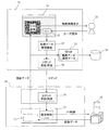
図1に、SEMの概略構成を示す。SEMは、電子銃1、陽極2、コンデンサレンズ3、偏向器5、対物レンズ6、試料台8、試料ステージ9、二次電子検出器11、増幅器12、画像記憶部13、主制御部14、コンピュータ部15、表示部16、入力装置(マウス17、キーボード18、専用操作パネル19)、記憶媒体20で構成される。記憶媒体20は、画像データベースを形成する。
FIG. 1 shows a schematic configuration of the SEM. The SEM includes an
電子銃1より放出された一次電子線4は、陽極2により制御・加速され、コンデンサレンズ3、偏向器5及び対物レンズ6を経て試料21の表面に収束・照射される。なお、試料21は、試料ステージ9上に搭載された試料台8に設置されている。また、一次電子線4に対する試料21の位置決めは、当該照射に先立ち、試料ステージ9の駆動制御を通じて実現される。
The
試料21の観察に必要な一連の制御は、主制御部14が実行する。主制御部14には、表示機能や入力機能を分担するコンピュータ部15が接続される。入力装置を通じて設定された観察条件等は、コンピュータ部15を通じて主制御部14に与えられる。なお、コンピュータ部15は、形態例1で説明した画像データの管理機能も提供する。表示部16は、ユーザ操作画面の表示に使用される。
The
観察位置の移動(一次電子線4の照射領域に対する試料21の移動)は、主制御部14によるステージ制御部10の制御を通じて実現される。ここで、ステージ制御部10は、主制御部14の指示に従い、試料ステージ9の駆動をする。
The movement of the observation position (the movement of the
試料21に一次電子線4を照射することで発生した二次電子7は、二次電子検出器11により検出される。二次電子検出器11から出力される検出信号は、増幅器12によって増幅された後、不図示のアナログ/デジタル変換器によってデジタル信号に変換され、その後、画像記憶部13に記憶される。以下、画像記憶部13に記憶されたデジタル信号を画像信号とも呼ぶ。画像信号は、コンピュータ部15によって読み出され、表示部16に観察画像として表示される。
本形態例においては、一次電子線4の照射により発生する二次信号の検出装置として二次電子検出器11のみを記載しているが、反射電子検出器、二次電子と反射電子の両方を検出可能な混合検出器その他を検出装置を使用しても良い。複数種類の検出装置を搭載することにより、様々な種類の画像データを取得できる。
In the present embodiment, only the
コンピュータ部15は、装置全体の制御だけでなく、画像データの解析処理も実行する。このため、コンピュータ部15では、制御やデータ解析処理を実行するためのプログラムが実行される。当該プログラムは、メニュー画面、GUI画面その他のユーザ操作画面を表示部16に表示する。当該プログラムは、ユーザ操作画面を通じ、装置の様々な状態を視覚的にユーザに提示すると共に、装置制御やデータ解析処理に必要な指示を操作者から受信する。
The
なお、画像データ及び属性データは、プログラム処理を通じ、記憶媒体(データベース格納エリア)20に保存される。この他、プログラムは、画像データ及び属性データの管理(削除、移動、複写、名前の変更、画像処理、検索、表示等)も提供する。 The image data and attribute data are stored in the storage medium (database storage area) 20 through program processing. In addition, the program also provides management of image data and attribute data (deletion, movement, copying, name change, image processing, search, display, etc.).
(画像データを取得する際の処理)
図2に、主制御部14とコンピュータ部15によって実行される画像データの取得処理動作を説明する。
(Process when acquiring image data)
FIG. 2 illustrates an image data acquisition processing operation executed by the
表示部16には、ユーザ操作画面23(メニュー画面、GUI画面、UI画面等)だけが表示されているものとする。操作者22は、このユーザ操作画面23に対する操作入力を通じ、画像データ管理機能部24による管理(保存、削除、移動、複写、名前の変更、画像処理、検索、表示等)を起動する。画像データ管理機能部24は、取得された画像データを保存する際の管理も提供する。
It is assumed that only the user operation screen 23 (menu screen, GUI screen, UI screen, etc.) is displayed on the
ここでは、操作者22が、画像データの一括保存を選択したものとする。一括保存とは、個々の画像データが得られるたびに保存処理をリアルタイムで実行するのとは異なり、テンポラリメモリエリア25に保存された複数の画像データを対象とする保存処理をいう。
Here, it is assumed that the
操作者22が当該機能を選択すると、コンピュータ部15は、当該機能の実行を指示するコマンドを、コマンド送信/受信部26を通じて主制御部14に送信する。当該コマンドは、主制御部14のコマンド送信/受信部26において受信される。受信されたコマンドは、鏡体制御部27に与えられる。鏡体制御部27は、鏡体28内に格納される電子銃1、陽極2、コンデンサレンズ3、偏向器5、対物レンズ6、ステージ制御部10との間に用意された入出力インターフェースを制御する。当該制御により、試料21の観察領域に対応する画像データが、鏡体28から画像記憶部13に格納される。
When the
この後、主制御部14は、画像記憶部13からコンピュータ部15に画像データを送信する。表示部16の画面上には、観察領域の画像がSEM画像として表示される。また、当該画像データは、コンピュータ部15のテンポラリメモリエリア25に保存される。この保存の際、コンピュータ部15は、画像データと対をなす属性データを生成し、当該属性データもテンポラリメモリエリア25に保存する。この後、コンピュータ部15は、データベース格納エリアとしての記憶媒体20に、画像データと属性データを格納する。この際、コンピュータ部15は、保存対象とする画像データと対をなす属性データの内容と一致するディレクトリ階層のフォルダに該当する画像データを保存する。
Thereafter, the
(属性データとディレクトリ階層の関係)
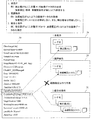
図3を用い、保存先となるフォルダが有するディレクトリ階層と属性データの内容との対応関係を示す。前述したように、コンピュータ部15のテンポラリメモリエリア25には、画像データと対をなす属性データ29が保存されている。図3には、属性データ29の記述例を示している。コンピュータ部15は、画像データを記憶媒体20に記憶する前に、対応する属性データの内容を読み出し、当該内容と一致するディレクトリ階層30が記憶媒体20に存在するか否か検索する。
(Relationship between attribute data and directory hierarchy)
FIG. 3 is used to show the correspondence between the directory hierarchy of the folder that is the storage destination and the contents of the attribute data. As described above, the
属性データ29の内容と一致するディレクトリ階層30が記憶媒体20に存在する場合、コンピュータ部15は、当該階層構造を有するフォルダ301を保存先に指定し、画像データと属性データ29を保存する。図3の場合、D:¥ユーザ名¥サンプル名¥日付¥検出器¥加速電圧¥倍率で与えられるフォルダに、画像データと属性データ29を保存する。
When the
一方、属性データ29の内容と一致するディレクトリ階層が記憶媒体20に存在しない場合、コンピュータ部15は、記憶媒体20に対応するディレクトリ階層を有する新規のフォルダ301を自動的に生成し、当該フォルダ301に画像データと属性データ29を保存する。すなわち、コンピュータ部15は、属性データ29からユーザ名、サンプル名、取得日、検出器(信号)、加速電圧、倍率等を順番に読み出し、読み出し順に階層が下位となるディレクトリ階層を記憶媒体20内に生成する。図3には、属性データ29とディレクトリ階層の対応関係を破線矢印で表している。
On the other hand, when there is no directory hierarchy that matches the contents of the
以上のように、本形態例に係るコンピュータ部15は、画像データの保存時に、属性データ29と一致するディレクトリ階層を有するフォルダを検索又は生成し、当該フォルダに属性データが共通する画像データを集約的に保存する。
As described above, when saving image data, the
この特性を利用し、コンピュータ部15は、ディレクトリ階層を検索対象とすることで、条件に合致する画像データを検索し、表示部16に表示することができる。結果的に、一括削除や一括画像処理(例えば移動、複写、名前の変更、検索、表示等)に必要な時間を最小化できる。勿論、このデータ管理手法は、画像データ単位で属性データを管理する場合に比して、操作者自身による管理が容易になる。
Using this characteristic, the
さらに、コンピュータ部15は、画像データの保存時に、自動的に任意の名前を付ける機能も有している。
Further, the
(観察条件の設定値によるディレクトリ階層の生成)
ここでは、観察条件の設定値に基づいたディレクトリ階層の生成と生成されたフォルダに基づく画像データの管理について説明する。
(Generate directory hierarchy based on observation condition settings)
Here, generation of a directory hierarchy based on setting values of observation conditions and management of image data based on the generated folder will be described.
図4及び図5に、観察条件の設定値を使用したディレクトリ階層の生成イメージを示す。なお、画像データの保存先となるディレクトリ階層の生成機能は、コンピュータ部15が提供する。
4 and 5 show a directory hierarchy generation image using the observation condition setting values. Note that the
前述したように、画像データは、基本的には属性データにより管理される。その一方で、操作者側からは、走査型電子顕微鏡の詳細な観察条件に基づいて画像データを管理したいとの要望も多い。そこで、前述した属性データの内容に基づくディレクトリ階層を有するフォルダ生成機能の他に、観察条件に基づくディレクトリ階層のフォルダ生成機能も搭載する。すなわち、本形態例の場合には、これら2種類のフォルダを用いて画像データを一括管理する。 As described above, image data is basically managed by attribute data. On the other hand, there are many requests from the operator side to manage image data based on detailed observation conditions of the scanning electron microscope. Therefore, in addition to the folder generation function having the directory hierarchy based on the contents of the attribute data described above, a folder generation function of the directory hierarchy based on the observation condition is also installed. That is, in the present embodiment, image data is collectively managed using these two types of folders.
図4は、操作者が使用する観察条件の一例を示している。観察条件には、例えば条件の絞込み条件がある。条件には、単条件、範囲条件、組合せ条件等がある。 FIG. 4 shows an example of the observation conditions used by the operator. The observation condition includes, for example, a condition narrowing condition. Conditions include single conditions, range conditions, combination conditions, and the like.
ここで、「単条件」とは、単一の値と一致するか否かを絞り込み条件とする場合に用いられる。例えば図4は、HVが0.3kVの画像データのみを保存、削除、移動、複写、名前の変更、画像処理、検索、表示等の対象とする例を示している。図5は、二次電子検出器からの画像データのみを保存対象とする例を示している。当該単条件を満たすフォルダは、ユーザ名の直下に生成される。 Here, the “single condition” is used when the narrowing condition is whether or not it matches a single value. For example, FIG. 4 shows an example in which only image data whose HV is 0.3 kV is to be stored, deleted, moved, copied, renamed, image processed, searched, displayed, and the like. FIG. 5 shows an example in which only image data from the secondary electron detector is stored. A folder that satisfies the simple condition is generated immediately under the user name.
当該フォルダには、条件を満たす限り、他の条件が異なる画像データも保存される。従って、図5の場合、加速電圧、倍率等が異なる画像データも同じフォルダに保存される。なお、図5の場合、属性データ29は、画像データが二次電子像であることを示している。このため、当該属性データに対応する画像データの保存は許される。
As long as the condition is satisfied, image data with different conditions is also stored in the folder. Therefore, in the case of FIG. 5, image data having different acceleration voltages, magnifications, and the like are also stored in the same folder. In the case of FIG. 5, the
「範囲条件」とは、値がある範囲内に属するか否かを絞り込み条件とする場合に用いられる。例えば図4は、観察時の倍率が1000〜10000倍の画像データのみを保存、削除、移動、複写、名前の変更、画像処理、検索、表示等の対象とする例を示している。図5は、加速電圧が1kV以下の画像データのみを保存対象とする例を示している。当該範囲条件を満たすフォルダも、ユーザ名の直下に生成される。 The “range condition” is used when the narrowing condition is whether the value belongs to a certain range. For example, FIG. 4 shows an example in which only image data with a magnification of 1000 to 10,000 times during observation is targeted for storage, deletion, movement, copying, name change, image processing, search, display, and the like. FIG. 5 shows an example in which only image data with an acceleration voltage of 1 kV or less is stored. A folder that satisfies the range condition is also generated immediately under the user name.
当該フォルダには、条件を満たす限り、他の条件が異なる画像データも保存される。図5の場合、属性データ29は、画像データの加速電圧が2kVであることを示している。このため、当該属性データに対応する画像データの保存は許されない。
As long as the condition is satisfied, image data with different conditions is also stored in the folder. In the case of FIG. 5, the
「組合せ条件」とは、複数の値や範囲の組合せを絞り込み条件とする場合に用いられる。例えば図4は、倍率が1000倍であり、かつ、W.D.が10mmの画像データのみを保存、削除、移動、複写、名前の変更、画像処理、検索、表示等の対象とする例を示している。図5は、検出器が二次電子検出器であり、かつ、加速電圧が5kV以下の画像データのみを保存対象とする例を示している。当該範囲条件を満たすフォルダも、ユーザ名の直下に生成される。 The “combination condition” is used when a combination of a plurality of values and ranges is used as a narrowing condition. For example, FIG. 4 shows an example of saving, deleting, moving, copying, renaming, image processing, searching, displaying, etc. only image data with a magnification of 1000 and WD of 10 mm. . FIG. 5 shows an example in which the detector is a secondary electron detector and only image data with an acceleration voltage of 5 kV or less is stored. A folder that satisfies the range condition is also generated immediately under the user name.
当該フォルダには、条件を満たす限り、他の条件が異なる画像データも保存される。図5の場合、属性データ29は、画像データは二次電子像であり、かつ、加速電圧が2kVであることを示している。このため、当該属性データに対応する画像データは、対応フォルダに保存される。
As long as the condition is satisfied, image data with different conditions is also stored in the folder. In the case of FIG. 5, the
以上の通り、コンピュータ部15は、画像データを記憶媒体20に保存する前に、画像データを取得する前に使用した観察条件に基づいて保存の可否を判定する。
As described above, before saving the image data in the
なお、画像データ管理機能部24には、記憶媒体20に画像データを保存する前に、観察条件に一致しない画像データの保存の有無を判定する機能を搭載することが望ましい。例えば画像データをデータベースに保存する前に、画質に基づいて保存の可否を判定することが望ましい。
It is desirable that the image data
一般には、画質が良好な画像(例えば焦点のあった画像)のみが保存対象に選択されるが、非焦点画像等の画質が必ずしも良好でない画像も保存対象とし、その他の観察条件に基づく判定を行っても良い。この他、画像データ管理機能部24には、画像データに施す画像処理の内容に応じてフォルダを生成し、当該フォルダに画像処理後の画像データを格納する機能を搭載しても良い。
In general, only images with good image quality (for example, focused images) are selected for storage, but images with poor image quality, such as non-focus images, are also targeted for storage, and judgment based on other observation conditions is made. You can go. In addition, the image data
いずれにしても、本形態例によれば、属性データだけでなく、観察条件(画像処理の内容を含む)の共通する画像データを一括して管理することが可能となり、画像データの管理を効率化することができる。なお、前述したように観察条件の一部は、属性データの一部項目とも重複している。従って、観察条件に基づく分類は、属性データの特定の項目に基づく管理とも考えることができる。 In any case, according to the present embodiment, it is possible to manage not only attribute data but also image data having a common observation condition (including the contents of image processing) in a batch, thereby efficiently managing image data. Can be As described above, some of the observation conditions overlap with some items of the attribute data. Therefore, classification based on observation conditions can be considered as management based on specific items of attribute data.
(画像データの複写及び移動)
続いて、前述したディレクトリ階層を有するフォルダに保存された画像データの管理機能の一例を説明する。ここでは、図6を用い、本形態例に特有の画像データの複写と移動動作を説明する。図6では、複写元又は移動元の記憶媒体20を記憶媒体Aとし、複写先又は移動先の記憶媒体20を記憶媒体Bとする。一般的なファイルの複写や移動は(図6の中段に示す例)、ファイルのみを対象として実行され、記憶媒体B上で指定されたフォルダにファイルだけが複写又は移動される。
(Copying and moving image data)
Next, an example of a management function for image data stored in a folder having the above-described directory hierarchy will be described. Here, the copying and moving operation of the image data unique to this embodiment will be described with reference to FIG. In FIG. 6, the
しかし、本形態例のコンピュータ部15は、特定の画像データを他の記憶媒体Bに複写又は移動する場合、画像データの属するフォルダのディレクトリ階層を検出し、移動先に指定された記憶媒体Bに同じディレクトリ階層が存在するか否かを判定する。もし記憶媒体Bにも同じディレクトリ階層が存在する場合、コンピュータ部15は、同フォルダに画像データを複写又は移動する(図6の下段に示す例)。
However, when copying or moving specific image data to another storage medium B, the
これに対し、記憶媒体Bに対応するディレクトリ階層が存在しない場合、コンピュータ部15は、記憶媒体Aのディレクトリ階層と同じディレクトリ階層を記憶媒体Bに生成し、その後、複写元又は移動元と同じフォルダに画像データを複写又は移動する。
On the other hand, when there is no directory hierarchy corresponding to the storage medium B, the
この動作は、フォルダ内で指定された個別の画像データの複写又は移動時にも実行され、勿論、フォルダ内に存在する複数の画像データを一括に複写又は移動する場合にも実行される。このように、本形態例の場合には、複写後又は移動後も同じディレクトリ階層で画像データが管理される。このため、記憶媒体の増設時にも、それまでと同じ管理手法を適用して多数の画像データの管理を継続できる。 This operation is also executed when copying or moving individual image data designated in the folder. Of course, this operation is also executed when copying or moving a plurality of image data existing in the folder at once. As described above, in the case of this embodiment, the image data is managed in the same directory hierarchy after copying or moving. For this reason, even when a storage medium is added, it is possible to continue managing a large number of image data by applying the same management method as before.
(フォルダ管理)
続いて、自動生成等されたフォルダの管理機能の一例を説明する。前述したように、この形態例の場合には、操作者の選択により、属性データや観察条件の内容に一致するディレクトリ階層のフォルダに画像データを自動的に保存し、当該フォルダ単位で複数の画像データを一括管理することができる。
(Folder management)
Next, an example of a folder management function that is automatically generated will be described. As described above, in the case of this embodiment, image data is automatically stored in a folder of a directory hierarchy that matches the contents of attribute data and observation conditions according to the selection of the operator, and a plurality of images are stored in units of the folder. Data can be managed collectively.
ただし、生成された階層構造が操作者の意図する管理基準と合致しない場合も考えられる。この場合に備え、本形態例の場合には、ユーザ操作画面上で生成されたディレクトリ構造を変更できるようにする。例えば操作者は、ユーザ操作画面上で、複数のフォルダや複数の階層を指定するフォルダを統合することができる。また、操作者は、ユーザ操作画面上で、1つのフォルダを複数のフォルダやサブフォルダに分割することができる。当該機能の搭載により、操作者は、意図するディレクトリ階層及び単位で画像データを管理することが可能になる。 However, there may be a case where the generated hierarchical structure does not match the management standard intended by the operator. In preparation for this case, in the case of this embodiment, the directory structure generated on the user operation screen can be changed. For example, the operator can integrate a plurality of folders and folders for specifying a plurality of hierarchies on the user operation screen. Further, the operator can divide one folder into a plurality of folders and subfolders on the user operation screen. By mounting the function, the operator can manage the image data in the intended directory hierarchy and unit.
(一括画像処理)
図7を用い、画像データ管理機能の一例である一括画像処理機能について説明する。コンピュータ部15による画像データ32の管理手法には、観察条件に基づいて保存の必要/不要を判定する場合と、画像データ32の画質(非焦点、ノイズ等)に基づいて必要/不要を判定する場合がある。
(Batch image processing)
A batch image processing function, which is an example of an image data management function, will be described with reference to FIG. In the management method of the
本形態例においては、画像データ32を記憶領域20に保存する前に、一括画像処理を実行し、不要な画像データ32が記憶領域20に保存される事態を未然に防止する。その目的は、不要な画像データ32による記憶容量の消費を防ぎ、管理の効率化を実現するためにある。もっとも、操作者が希望する場合には、不要と判定される画像データを記憶媒体20に保存しても良い。
In the present embodiment, the batch image processing is executed before the
ここでは、一括画像処理として、正焦点画像データか否かの判定処理を想定する。すなわち、正焦点画像データと判定された場合にのみ、画像データを記憶媒体20に保存する場合について説明する。
Here, it is assumed that the batch image processing is processing for determining whether or not the data is regular focus image data. That is, a case will be described in which image data is stored in the
なお、判定処理には、判定閾値の設定が必要である。判定閾値は、設計データや経験値等に基づいて事前に与えられているものとする。例えば試料(半導体デバイス等)の設計データと観察条件から想定される定量的な線幅(具体的な数値はCADデータが用いられる)を閾値35として用意する。
In the determination process, it is necessary to set a determination threshold value. It is assumed that the determination threshold is given in advance based on design data, experience values, and the like. For example, a quantitative line width (CAD data is used as a specific numerical value) assumed from design data and observation conditions of a sample (semiconductor device or the like) is prepared as the
コンピュータ部15は、取得された画像データを測長し、測長結果34を閾値35と比較する。図7の場合、画像データに画像処理を施すことで得られる波形表示33から波形の線幅を測長し、当該測長結果34と閾値35を比較することにより、画像データの画質を判定する。なお、測長結果34と閾値35の比較に際しては、マージン36を考慮する。この形態例場合、マージン36は、設計段階で線幅値(すなわち閾値35)の±5%等に設定する。もっとも、マージン36の大きさは、操作者が観察条件、試料等を考慮して変更できるようにしても良い。因みに、保存が不要と判定された場合、コンピュータ部15は、記憶媒体20への保存処理を行わず、削除処理37を実行する。
The
この他、一括画像処理には、画像データ全体にCG法を適用して分解能を計測し、計測結果と閾値との比較に基づいて画像データの必要性を判定する手法も考えられる。例えば計測結果が予め定めた分解能値の範囲外の場合、保存が不要なデータと判定する。 In addition, for batch image processing, a method of measuring the resolution by applying the CG method to the entire image data and determining the necessity of the image data based on a comparison between the measurement result and a threshold value can be considered. For example, when the measurement result is outside the range of the predetermined resolution value, it is determined that the data does not need to be saved.
以上の処理は、テンポラリメモリエリア25に保存された複数の画像データを対象とし、バッチ処理として実行される。すなわち、テンポラリメモリエリア25に複数の画像データが保存された後に実行される。しかし、テンポラリメモリエリア25に画像データを保存するタイミング(すなわち、リアルタイム)に、前述した画像処理を行うこともできる。この場合、画像データの必要/不要がテンポラリメモリエリア25への保存と同時に判定される。このため、不要と判定された画像データをリアルタイムでテンポラリメモリエリア25から削除することもできる。
The above process is executed as a batch process for a plurality of image data stored in the
なお、これらの画像処理は、操作者の指示とは無関係に自動実行することも可能である。ただし、その場合には、処理結果を示すメッセージを表示し、判定結果を操作者に確認しても良い。 Note that these image processes can also be automatically executed regardless of the operator's instructions. However, in that case, a message indicating the processing result may be displayed and the determination result may be confirmed with the operator.
(ユーザ操作画面)
続いて、ユーザ操作画面23の表示例を説明する。この形態例の場合、操作者は、ユーザ操作画面23を通じ、保存、削除、移動、複写、名前の変更、画像処理、検索、表示のいずれかの一括管理機能を実行できる。
(User operation screen)
Subsequently, a display example of the
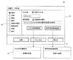
図8に示すユーザ操作画面23は、機能選択エリア38で「保存」が選択された場合の表示例を表している。このため、図8の場合には、保存専用のメニュー画面39が表示されている。保存専用のメニュー画面39には、ファイル名の表示欄、保存場所の表示欄、ファイル名詳細設定ボタン、保存場所詳細設定ボタン、更新ボタン、キャンセルボタン、閉じるボタン等が表示される。
A
ファイル名の表示欄の近傍位置には、ファイル名の自動設定機能を有効化するか否かを指定するチェックボックスが表示されている。また、保存場所の表示欄の近傍位置には、保存場所の自動設定機能を有効化するか否かを指定するチェックボックスが表示されている。図8の場合、保存場所の自動設定機能が有効化されており、保存場所の表示欄には、属性データから生成されたディレクトリ階層が表示されている。なお、ファイル名を作業者が個別に設定したい場合には、ファイル名詳細設定40が表示され、保存場所を作業者が個別に設定したい場合には、保存場所詳細設定41が表示される。 In the vicinity of the file name display column, a check box for specifying whether or not to enable the automatic file name setting function is displayed. Also, a check box for designating whether or not to enable the automatic setting function of the storage location is displayed near the storage location display field. In the case of FIG. 8, the automatic setting function of the storage location is enabled, and the directory hierarchy generated from the attribute data is displayed in the storage location display column. If the worker wants to individually set the file name, the file name detailed setting 40 is displayed. If the worker wants to individually set the storage location, the storage location detailed setting 41 is displayed.
図9に示すユーザ操作画面23は、機能選択エリア38で「画像処理」が選択された場合の画面例を表している。このため、図9の場合には、画像処理専用のメニュー画面42が表示されている。画像処理専用のメニュー画面42には、非焦点処理選択用のボタン、明るさ調整選択用のボタン、分解能算出処理選択用のボタン、画質改善処理選択用のボタン等が表示される。各選択用のボタンの近傍には詳細条件設定用のボタンが表示される。各ボタンの選択により、サブメニュー43が表示され、対応する処理の詳細設定が可能になる。例えば判定閾値等の設定が可能になる。
A
(処理手順全体)
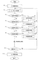
図10に、コンピュータ部15で実行される処理手順の概要を示す。まず、コンピュータ部15は、図8や図9に示すユーザ操作画面23を表示する(ステップS1)。次に、コンピュータ15は、操作者による操作入力を待ち受ける状態になる(ステップS2)。
(Whole procedure)
FIG. 10 shows an outline of a processing procedure executed by the
コンピュータ部15は、いずれの機能が操作されたかを順番に判定する(ステップS3、S5、S7、S9)。いずれかの判定処理において肯定結果が得られると、コンピュータ部15は、対応するサブルーチン処理を実行する(ステップS4、S6、S8、S10)。なお、画像データと対で生成される属性データの内容と対応したディレクトリ階層の検索処理や生成処理は、各サブルーチンの先頭処理として実行される。各処理の実行後、コンピュータ部15は、ステップS2に戻る。
The
これに対し、いずれの機能も選択されていなかった場合(ステップS3、S5、S7、S9で否定結果の場合)、コンピュータ部15は、操作終了か否かを判定する(ステップS11)。例えば閉じるボタンが操作されたか否かを判定する。否定結果が得られた場合、コンピュータ部15は、ステップS2に戻る。一方、肯定結果が得られた場合、コンピュータ部15は、ユーザ操作画面23を消去し(ステップS12)、一連の処理を終了する。
On the other hand, when no function is selected (in the case of negative results in steps S3, S5, S7, and S9), the
(まとめ)
以上の通り、本形態例に係る走査型電子顕微鏡を用いれば、大量に発生する画像データを共通の属性データを有する画像データに対して用意されたフォルダ単位で管理できる。すなわち、操作者は、フォルダ単位で画像データを管理することができる。フォルダ単位で大量の画像データを管理できるため、管理の効率化を実現できる。
(Summary)
As described above, when the scanning electron microscope according to this embodiment is used, a large amount of image data can be managed in units of folders prepared for image data having common attribute data. That is, the operator can manage the image data in units of folders. Since a large amount of image data can be managed in folder units, management efficiency can be improved.
また、本形態例に係る走査型電子顕微鏡は、各画像データの属性データの内容と一致するディレクトリ階層を自動的に生成することができる。この階層構造は、属性データの内容を表しているため、個別の属性データを読み出さなくても、ディレクトリ階層で特定される位置のフォルダに保存されている画像データに共通する性質の判定を効率よく行うことができる。すなわち、処理負荷を低減できる。 In addition, the scanning electron microscope according to the present embodiment can automatically generate a directory hierarchy that matches the contents of the attribute data of each image data. Since this hierarchical structure represents the contents of attribute data, it is possible to efficiently determine characteristics common to image data stored in a folder at a position specified in the directory hierarchy without reading individual attribute data. It can be carried out. That is, the processing load can be reduced.
また、本形態例の場合には、あるフォルダに保存されている単一の又は複数の画像データを他の記憶媒体に複写又は移動する場合でも、元の記憶媒体のディレクトリ階層を保持したまま、画像データの複写又は移動を行うことができる。従って、記憶媒体の増設時にも、既存のデータ管理と全く同じデータ管理を継続することができる。 In the case of this embodiment, even when copying or moving a single image data or a plurality of image data stored in a folder to another storage medium, the directory hierarchy of the original storage medium is maintained. Image data can be copied or moved. Therefore, even when the storage medium is added, the same data management as the existing data management can be continued.
また、本形態例の場合には、ユーザ操作画面を通じ、自動的に生成されたディレクトリ階層のフォルダの細分化、統合化その他の変更指示を操作者の意思に基づき行うことができる。従って、操作者の使い勝手を向上することができる。 In the case of this embodiment, subdivision, integration, and other change instructions for automatically generated folders in the directory hierarchy can be performed based on the operator's intention through the user operation screen. Therefore, the convenience of the operator can be improved.
また、本形態例の場合には、記憶媒体20の所定のフォルダに保存する前に、画像データの保存の可否を観察条件や画質に基づいて判定するため、不要な画像データによる記憶容量の消費を防止することができる。
In the case of the present embodiment, the storage capacity consumption due to unnecessary image data is determined in order to determine whether or not image data can be saved based on observation conditions and image quality before saving in a predetermined folder of the
また、本形態例の場合には、画像データの画質の判定に使用する閾値を観察条件及び又は試料に応じて自由に変更することができる。このため、判定結果を操作者の意図に近づけることができる。 In the case of this embodiment, the threshold value used for determining the image quality of the image data can be freely changed according to the observation conditions and / or the sample. For this reason, the determination result can be brought close to the operator's intention.
また、本形態例の場合には、一括画像処理処理の結果を操作者に報知する機能を用意したことにより、処理結果の良否を操作者の観点から確認することができる。 In the case of this embodiment, the function of notifying the operator of the result of the batch image processing process is prepared, so that the quality of the processing result can be confirmed from the viewpoint of the operator.
<他の形態例>
なお、本発明は上述した実施例に限定されるものでなく、様々な変形例が含まれる。例えば、上述した実施例は本発明を分かりやすく説明するために詳細に説明したものであり、必ずしも説明した全ての構成を備えるものに限定されるものではない。また、ある実施例の一部を他の実施例の構成に置き換えることが可能であり、また、ある実施例の構成に他の実施例の構成を加えることも可能である。また、各実施例の構成の一部について、他の構成を追加、削除又は置換することも可能である。
<Other forms>
In addition, this invention is not limited to the Example mentioned above, Various modifications are included. For example, the above-described embodiments have been described in detail for easy understanding of the present invention, and are not necessarily limited to those having all the configurations described. Further, a part of a certain embodiment can be replaced with a configuration of another embodiment, and a configuration of another embodiment can be added to a configuration of a certain embodiment. Moreover, it is also possible to add, delete, or replace another configuration for a part of the configuration of each embodiment.
また、上述した各構成、機能、処理部、処理手段等は、それらの一部又は全部を、例えば集積回路その他のハードウェアとして実現しても良い。また、上記の各構成、機能等は、プロセッサがそれぞれの機能を実現するプログラムを解釈し、実行することにより実現しても良い。すなわち、ソフトウェアとして実現しても良い。各機能を実現するプログラム、テーブル、ファイル等の情報は、メモリやハードディスク、SSD(Solid State Drive)等の記憶装置、ICカード、SDカード、DVD等の記憶媒体に格納することができる。 Moreover, you may implement | achieve some or all of each structure, a function, a process part, a process means, etc. which were mentioned above as an integrated circuit or other hardware, for example. Each of the above-described configurations, functions, and the like may be realized by the processor interpreting and executing a program that realizes each function. That is, it may be realized as software. Information such as programs, tables, and files for realizing each function can be stored in a memory, a hard disk, a storage device such as an SSD (Solid State Drive), or a storage medium such as an IC card, an SD card, or a DVD.
また、制御線や情報線は、説明上必要と考えられるものを示すものであり、製品上必要な全ての制御線や情報線を表すものでない。実際にはほとんど全ての構成が相互に接続されていると考えて良い。 Control lines and information lines indicate what is considered necessary for the description, and do not represent all control lines and information lines necessary for the product. In practice, it can be considered that almost all components are connected to each other.
1 電子銃
2 陽極
3 コンデンサレンズ
4 電子線
5 偏向器
6 対物レンズ
7 二次電子
8 試料台
9 試料ステージ
10 ステージ制御部
11 二次電子検出器
12 増幅器
13 画像記憶部
14 主制御部
15 コンピュータ部
16 表示部
17 マウス
18 キーボード
19 専用操作パネル
20 記憶媒体
21 試料
22 操作者
23 ユーザ操作画面
24 画像データ管理機能部
25 テンポラリメモリエリア
26 コマンド送信/受信部
27 鏡体制御部
28 鏡体
29 属性データ
30 ディレクトリ階層
DESCRIPTION OF
Claims (15)
荷電粒子線を試料に照射し、試料から出力される二次信号を検出する検出器と、
前記二次信号から生成された画像データを記憶する画像記憶部と、
前記画像データを表示する表示部と、
荷電粒子線に対する試料の位置関係を制御する駆動機構と、
操作部と、
前記画像データと共に生成される属性データの内容と一対の関係を有するディレクトリ階層のフォルダが前記画像記憶部に既に存在する場合には、当該フォルダを前記画像データの保存先に指定し、前記属性データの内容と一対の関係を有するディレクトリ階層のフォルダが前記画像記憶部に存在しない場合には、当該ディレクトリ階層を有するフォルダを前記画像記憶部に自動的に生成すると共に当該フォルダを前記画像データの保存先に指定する画像管理部と
を有することを特徴とする荷電粒子線装置。 In charged particle beam equipment,
A detector that irradiates the sample with a charged particle beam and detects a secondary signal output from the sample;
An image storage unit for storing image data generated from the secondary signal;
A display unit for displaying the image data;
A drive mechanism for controlling the positional relationship of the sample with respect to the charged particle beam;
An operation unit;
When a folder of a directory hierarchy having a pair relationship with the content of attribute data generated together with the image data already exists in the image storage unit, the folder is designated as a storage destination of the image data, and the attribute data If there is no directory hierarchy folder having a pair relationship with the contents of the image storage section, the folder having the directory hierarchy is automatically generated in the image storage section, and the folder stores the image data. A charged particle beam device comprising: an image management unit that is designated in advance.
前記画像管理部は、前記ディレクトリ階層とは別に、観察条件の設定値に対応するディレクトリ階層のフォルダを画像データの保存先に指定する
ことを特徴とする荷電粒子線装置。 The charged particle beam apparatus according to claim 1,
The charged particle beam apparatus, wherein the image management unit designates a folder of a directory hierarchy corresponding to a set value of an observation condition as a storage destination of image data separately from the directory hierarchy.
前記観察条件の設定値は、単条件、範囲条件若しくは組合せ条件又はこれらの組合せである
ことを特徴とする荷電粒子線装置。 The charged particle beam apparatus according to claim 2,
The set value of the observation condition is a single condition, a range condition, a combination condition, or a combination thereof.
前記画像管理部は、画像データを保存するフォルダのディレクトリ階層を保持したまま、前記画像データを他の記憶媒体に複写又は移動する機能を有する
ことを特徴とする荷電粒子線装置。 The charged particle beam apparatus according to claim 1,
The charged particle beam apparatus, wherein the image management unit has a function of copying or moving the image data to another storage medium while maintaining a directory hierarchy of a folder for storing image data.
前記画像管理部は、自動的に生成された前記ディレクトリ階層を構成するフォルダの細分化、統合化その他の変更指示を受け付けるユーザ操作画面を、前記表示部に表示する機能を有する
ことを特徴とする荷電粒子線装置。 The charged particle beam apparatus according to claim 1,
The image management unit has a function of displaying, on the display unit, a user operation screen that accepts a subdivision, integration, and other change instructions for folders that constitute the automatically generated directory hierarchy. Charged particle beam device.
前記画像管理部は、前記画像データを前記画像記憶部の所定のフォルダに保存する前に、画像データを取得する際に使用した観察条件に基づいて保存の可否を判定する
ことを特徴とする荷電粒子線装置。 The charged particle beam apparatus according to claim 1,
The image management unit determines whether or not the image data can be stored based on an observation condition used when acquiring the image data before storing the image data in a predetermined folder of the image storage unit. Particle beam device.
前記画像管理部は、前記画像データを前記画像記憶部の所定のフォルダに保存する前に、生成された画像データの画質に基づいて保存の可否を判定する
ことを特徴とする荷電粒子線装置。 The charged particle beam apparatus according to claim 1,
The charged particle beam apparatus, wherein the image management unit determines whether or not the image data can be stored based on the image quality of the generated image data before storing the image data in a predetermined folder of the image storage unit.
前記画像データの画質の判定に使用する閾値は、観察条件及び又は試料に応じて変更可能である
ことを特徴とする荷電粒子線装置。 The charged particle beam device according to claim 7,
The charged particle beam apparatus, wherein a threshold value used for determination of image quality of the image data can be changed according to an observation condition and / or a sample.
前記画像管理部は、当該処理結果をユーザに報知する機能を有する
ことを特徴とする荷電粒子線装置。 The charged particle beam apparatus according to claim 1,
The charged particle beam device, wherein the image management unit has a function of notifying a user of the processing result.
前記画像データと共に生成される属性データの内容と一対の関係を有するディレクトリ階層のフォルダが画像記憶部に既に存在する場合には、当該フォルダを前記画像データの保存先に指定する処理と、
前記属性データの内容と一対の関係を有するディレクトリ階層のフォルダが前記画像記憶部に存在しない場合には、当該ディレクトリ階層を有するフォルダを前記画像記憶部に自動的に生成すると共に当該フォルダを前記画像データの保存先に指定する処理と、
自動生成された前記ディレクトリ階層のフォルダを画像データの保存先として、ユーザ操作画面に表示する処理と
を有することを特徴とする画像データ管理方法。 In a method for managing image data acquired in a charged particle beam device,
When a folder of a directory hierarchy having a pair relationship with the content of attribute data generated together with the image data already exists in the image storage unit, a process of designating the folder as a storage destination of the image data;
When a folder of a directory hierarchy having a pair relationship with the content of the attribute data does not exist in the image storage unit, a folder having the directory hierarchy is automatically generated in the image storage unit and the folder is added to the image storage unit. Processing to specify the data storage destination,
And a process of displaying the automatically generated folder of the directory hierarchy on a user operation screen as a storage destination of the image data.
前記ディレクトリ階層とは別に、観察条件の設定値に対応するディレクトリ階層のフォルダを画像データの保存先に指定する処理を有する
ことを特徴とする画像データ管理方法。 The image data management method according to claim 10 comprises:
In addition to the directory hierarchy, there is a process of designating a folder of the directory hierarchy corresponding to the set value of the observation condition as a storage destination of the image data.
画像データを保存するフォルダのディレクトリ階層を保持したまま、前記画像データを他の記憶媒体に複写又は移動する処理を有する
ことを特徴とする画像データ管理方法。 The image data management method according to claim 10 comprises:
An image data management method, comprising: a process of copying or moving the image data to another storage medium while maintaining a directory hierarchy of a folder for storing the image data.
自動的に生成された前記ディレクトリ階層を構成するフォルダの細分化、統合化その他の変更指示を受け付ける画面を前記ユーザ操作画面に表示する処理を有する
ことを特徴とする画像データ管理方法。 The image data management method according to claim 10 comprises:
An image data management method comprising: displaying a screen for accepting a subdivision, integration, or other change instruction for folders constituting the directory hierarchy automatically generated on the user operation screen.
前記画像データを前記画像記憶部の所定のフォルダに保存する前に、画像データを取得する際に使用した観察条件に基づいて保存の可否を判定する処理を有する
ことを特徴とする画像データ管理方法。 The image data management method according to claim 10 comprises:
An image data management method comprising a process of determining whether or not the image data can be stored based on an observation condition used when acquiring the image data before the image data is stored in a predetermined folder of the image storage unit. .
前記画像データを前記画像記憶部の所定のフォルダに保存する前に、生成された画像データの画質に基づいて保存の可否を判定する処理を有する
ことを特徴とする画像データ管理方法。 The image data management method according to claim 10 comprises:
An image data management method comprising: determining whether or not to save the image data based on an image quality of the generated image data before saving the image data in a predetermined folder of the image storage unit.
Priority Applications (1)
| Application Number | Priority Date | Filing Date | Title |
|---|---|---|---|
| JP2011002408A JP2012146421A (en) | 2011-01-07 | 2011-01-07 | Charged particle beam device and method for managing image data |
Applications Claiming Priority (1)
| Application Number | Priority Date | Filing Date | Title |
|---|---|---|---|
| JP2011002408A JP2012146421A (en) | 2011-01-07 | 2011-01-07 | Charged particle beam device and method for managing image data |
Publications (1)
| Publication Number | Publication Date |
|---|---|
| JP2012146421A true JP2012146421A (en) | 2012-08-02 |
Family
ID=46789835
Family Applications (1)
| Application Number | Title | Priority Date | Filing Date |
|---|---|---|---|
| JP2011002408A Pending JP2012146421A (en) | 2011-01-07 | 2011-01-07 | Charged particle beam device and method for managing image data |
Country Status (1)
| Country | Link |
|---|---|
| JP (1) | JP2012146421A (en) |
Citations (8)
| Publication number | Priority date | Publication date | Assignee | Title |
|---|---|---|---|---|
| JPH0868798A (en) * | 1994-08-30 | 1996-03-12 | Shimadzu Corp | Scanning type probe microscope |
| JP2001126007A (en) * | 1999-10-29 | 2001-05-11 | Toshiba Corp | Report generation support system |
| JP2001155672A (en) * | 1999-11-30 | 2001-06-08 | Hitachi Ltd | Electron microscope and image displaying method |
| JP2001290683A (en) * | 2000-04-05 | 2001-10-19 | Nikon Corp | File-managing device and recording medium with file management program recorded thereon |
| WO2002023480A1 (en) * | 2000-09-18 | 2002-03-21 | Olympus Optical Co., Ltd. | System and method for managing image data file |
| JP2006506816A (en) * | 2002-11-12 | 2006-02-23 | エフ・イ−・アイ・カンパニー | Defect analyzer |
| JP2006268401A (en) * | 2005-03-24 | 2006-10-05 | Brother Ind Ltd | Associated information writing program, associated information writing apparatus and associated information writing method |
| JP2009210773A (en) * | 2008-03-04 | 2009-09-17 | Nikon Corp | Information processing apparatus for image of microscope |
-
2011
- 2011-01-07 JP JP2011002408A patent/JP2012146421A/en active Pending
Patent Citations (8)
| Publication number | Priority date | Publication date | Assignee | Title |
|---|---|---|---|---|
| JPH0868798A (en) * | 1994-08-30 | 1996-03-12 | Shimadzu Corp | Scanning type probe microscope |
| JP2001126007A (en) * | 1999-10-29 | 2001-05-11 | Toshiba Corp | Report generation support system |
| JP2001155672A (en) * | 1999-11-30 | 2001-06-08 | Hitachi Ltd | Electron microscope and image displaying method |
| JP2001290683A (en) * | 2000-04-05 | 2001-10-19 | Nikon Corp | File-managing device and recording medium with file management program recorded thereon |
| WO2002023480A1 (en) * | 2000-09-18 | 2002-03-21 | Olympus Optical Co., Ltd. | System and method for managing image data file |
| JP2006506816A (en) * | 2002-11-12 | 2006-02-23 | エフ・イ−・アイ・カンパニー | Defect analyzer |
| JP2006268401A (en) * | 2005-03-24 | 2006-10-05 | Brother Ind Ltd | Associated information writing program, associated information writing apparatus and associated information writing method |
| JP2009210773A (en) * | 2008-03-04 | 2009-09-17 | Nikon Corp | Information processing apparatus for image of microscope |
Similar Documents
| Publication | Publication Date | Title |
|---|---|---|
| JP6348504B2 (en) | Biological sample split screen display and system and method for capturing the records | |
| Mitchell et al. | Scripting-customised microscopy tools for Digital Micrograph™ | |
| JP2019533805A (en) | Digital pathology system and associated workflow for providing visualized slide-wide image analysis | |
| Gallagher et al. | Negative‐stain transmission electron microscopy of molecular complexes for image analysis by 2D class averaging | |
| WO2012165044A1 (en) | Image display device, image display system, and image display method | |
| TW201403488A (en) | Pattern matching method and apparatus | |
| JP2011113776A (en) | Charged-particle microscope, and control method for charged-particle microscope | |
| Dominguez et al. | The use of ROI overlays and a semi‐automated method for measuring cortical area in ImageJ for histological analysis | |
| JP4709168B2 (en) | Report search method, report search system, and review device | |
| JP5977200B2 (en) | Electron microscope and electron microscope control method | |
| JP2012146421A (en) | Charged particle beam device and method for managing image data | |
| JP2019087369A (en) | Electron microscope and program | |
| JP5401214B2 (en) | Charged particle beam device and operation screen thereof | |
| WO2016204241A1 (en) | Image processing device, image processing method, program, and recording medium | |
| JPH06274504A (en) | Business analysis flow chart editing system | |
| JP2006337354A (en) | Processor and method for processing nmr data | |
| US6778944B2 (en) | Method and system for managing data | |
| JP2011141298A (en) | Processing device and method of nmr data | |
| US10269535B2 (en) | Information processing device and information processing method | |
| TW201443642A (en) | Charged particle beam writing apparatus, and buffer memory data storage method | |
| US11455333B1 (en) | Systems and methods of metadata and image management for reviewing data from transmission electron microscope (TEM) sessions | |
| WO2023242954A1 (en) | Charged particle beam device and method for outputting image data of interest | |
| WO2024052986A1 (en) | Observation assistance device | |
| US20230289943A1 (en) | Information processing apparatus, information processing method, and medium | |
| US20230083479A1 (en) | Scatter Diagram Display Device, Scatter Diagram Display Method, and Analyzer |
Legal Events
| Date | Code | Title | Description |
|---|---|---|---|
| A621 | Written request for application examination |
Free format text: JAPANESE INTERMEDIATE CODE: A621 Effective date: 20130129 |
|
| A977 | Report on retrieval |
Free format text: JAPANESE INTERMEDIATE CODE: A971007 Effective date: 20130905 |
|
| A131 | Notification of reasons for refusal |
Free format text: JAPANESE INTERMEDIATE CODE: A131 Effective date: 20131105 |
|
| A521 | Written amendment |
Free format text: JAPANESE INTERMEDIATE CODE: A523 Effective date: 20131220 |
|
| A131 | Notification of reasons for refusal |
Free format text: JAPANESE INTERMEDIATE CODE: A131 Effective date: 20140527 |
|
| A521 | Written amendment |
Free format text: JAPANESE INTERMEDIATE CODE: A523 Effective date: 20140618 |
|
| A02 | Decision of refusal |
Free format text: JAPANESE INTERMEDIATE CODE: A02 Effective date: 20141125 |