JP2012135308A - Apparatus and method for sorting particle and for providing sex-sorted animal sperm - Google Patents
Apparatus and method for sorting particle and for providing sex-sorted animal sperm Download PDFInfo
- Publication number
- JP2012135308A JP2012135308A JP2012008334A JP2012008334A JP2012135308A JP 2012135308 A JP2012135308 A JP 2012135308A JP 2012008334 A JP2012008334 A JP 2012008334A JP 2012008334 A JP2012008334 A JP 2012008334A JP 2012135308 A JP2012135308 A JP 2012135308A
- Authority
- JP
- Japan
- Prior art keywords
- cells
- sperm
- sorting
- particles
- pulse
- Prior art date
- Legal status (The legal status is an assumption and is not a legal conclusion. Google has not performed a legal analysis and makes no representation as to the accuracy of the status listed.)
- Granted
Links
- 239000002245 particle Substances 0.000 title claims abstract description 1170
- 238000000034 method Methods 0.000 title abstract description 716
- 241001465754 Metazoa Species 0.000 title abstract description 47
- 238000000684 flow cytometry Methods 0.000 claims abstract description 314
- 239000012530 fluid Substances 0.000 claims description 823
- 238000012384 transportation and delivery Methods 0.000 claims description 189
- 239000000203 mixture Substances 0.000 claims description 109
- 230000008859 change Effects 0.000 claims description 45
- 230000006872 improvement Effects 0.000 claims description 17
- 210000004027 cell Anatomy 0.000 abstract description 1343
- 238000010186 staining Methods 0.000 abstract description 123
- 230000008569 process Effects 0.000 abstract description 107
- 238000005286 illumination Methods 0.000 abstract description 97
- 238000012545 processing Methods 0.000 abstract description 72
- 238000005070 sampling Methods 0.000 abstract description 38
- 238000004458 analytical method Methods 0.000 abstract description 28
- 238000000605 extraction Methods 0.000 abstract description 23
- 238000004043 dyeing Methods 0.000 abstract description 11
- 230000009027 insemination Effects 0.000 abstract description 11
- 230000001360 synchronised effect Effects 0.000 abstract description 9
- 210000003765 sex chromosome Anatomy 0.000 abstract description 4
- 210000003855 cell nucleus Anatomy 0.000 abstract 1
- 239000000523 sample Substances 0.000 description 225
- 230000006870 function Effects 0.000 description 172
- 230000003287 optical effect Effects 0.000 description 136
- 239000000872 buffer Substances 0.000 description 102
- 210000000582 semen Anatomy 0.000 description 100
- 238000001816 cooling Methods 0.000 description 97
- 108020004414 DNA Proteins 0.000 description 96
- 239000000725 suspension Substances 0.000 description 68
- 230000005670 electromagnetic radiation Effects 0.000 description 63
- 230000004899 motility Effects 0.000 description 63
- XLYOFNOQVPJJNP-UHFFFAOYSA-N water Substances O XLYOFNOQVPJJNP-UHFFFAOYSA-N 0.000 description 60
- 238000001514 detection method Methods 0.000 description 53
- 239000002577 cryoprotective agent Substances 0.000 description 52
- 229910001868 water Inorganic materials 0.000 description 52
- 238000005119 centrifugation Methods 0.000 description 51
- 108090000623 proteins and genes Proteins 0.000 description 50
- 239000010902 straw Substances 0.000 description 50
- 102000004169 proteins and genes Human genes 0.000 description 49
- 230000001965 increasing effect Effects 0.000 description 48
- 238000010586 diagram Methods 0.000 description 46
- 230000005855 radiation Effects 0.000 description 45
- 210000001766 X chromosome Anatomy 0.000 description 44
- 239000000975 dye Substances 0.000 description 44
- PRDFBSVERLRRMY-UHFFFAOYSA-N 2'-(4-ethoxyphenyl)-5-(4-methylpiperazin-1-yl)-2,5'-bibenzimidazole Chemical compound C1=CC(OCC)=CC=C1C1=NC2=CC=C(C=3NC4=CC(=CC=C4N=3)N3CCN(C)CC3)C=C2N1 PRDFBSVERLRRMY-UHFFFAOYSA-N 0.000 description 39
- PEDCQBHIVMGVHV-UHFFFAOYSA-N Glycerine Chemical compound OCC(O)CO PEDCQBHIVMGVHV-UHFFFAOYSA-N 0.000 description 39
- 238000005138 cryopreservation Methods 0.000 description 39
- 238000001914 filtration Methods 0.000 description 35
- 238000011084 recovery Methods 0.000 description 34
- IJGRMHOSHXDMSA-UHFFFAOYSA-N Atomic nitrogen Chemical compound N#N IJGRMHOSHXDMSA-UHFFFAOYSA-N 0.000 description 32
- 238000004163 cytometry Methods 0.000 description 32
- 230000007423 decrease Effects 0.000 description 32
- 210000004940 nucleus Anatomy 0.000 description 32
- 241000283690 Bos taurus Species 0.000 description 31
- 210000002969 egg yolk Anatomy 0.000 description 31
- 239000008188 pellet Substances 0.000 description 31
- 238000012360 testing method Methods 0.000 description 31
- 108010000912 Egg Proteins Proteins 0.000 description 30
- 102000002322 Egg Proteins Human genes 0.000 description 30
- 238000009826 distribution Methods 0.000 description 30
- 235000013345 egg yolk Nutrition 0.000 description 30
- 210000002593 Y chromosome Anatomy 0.000 description 29
- 239000000654 additive Substances 0.000 description 29
- 230000006378 damage Effects 0.000 description 29
- 239000006228 supernatant Substances 0.000 description 29
- 239000004606 Fillers/Extenders Substances 0.000 description 28
- 238000011144 upstream manufacturing Methods 0.000 description 28
- 230000008901 benefit Effects 0.000 description 25
- 230000008832 photodamage Effects 0.000 description 25
- 239000000463 material Substances 0.000 description 24
- 230000002829 reductive effect Effects 0.000 description 24
- 239000000243 solution Substances 0.000 description 24
- 230000015572 biosynthetic process Effects 0.000 description 23
- 238000004422 calculation algorithm Methods 0.000 description 23
- 239000002699 waste material Substances 0.000 description 23
- 244000309464 bull Species 0.000 description 22
- 230000001976 improved effect Effects 0.000 description 22
- 239000007788 liquid Substances 0.000 description 22
- 230000002759 chromosomal effect Effects 0.000 description 20
- 230000004720 fertilization Effects 0.000 description 20
- LENZDBCJOHFCAS-UHFFFAOYSA-N tris Chemical compound OCC(N)(CO)CO LENZDBCJOHFCAS-UHFFFAOYSA-N 0.000 description 20
- 108091003079 Bovine Serum Albumin Proteins 0.000 description 19
- 229940098773 bovine serum albumin Drugs 0.000 description 19
- 238000011156 evaluation Methods 0.000 description 18
- 238000012423 maintenance Methods 0.000 description 17
- 239000002953 phosphate buffered saline Substances 0.000 description 17
- 230000019100 sperm motility Effects 0.000 description 17
- 238000003860 storage Methods 0.000 description 17
- 239000007789 gas Substances 0.000 description 16
- 235000013336 milk Nutrition 0.000 description 16
- 239000008267 milk Substances 0.000 description 16
- 210000004080 milk Anatomy 0.000 description 16
- 229910052757 nitrogen Inorganic materials 0.000 description 16
- 230000000750 progressive effect Effects 0.000 description 16
- 238000000926 separation method Methods 0.000 description 16
- 238000012546 transfer Methods 0.000 description 16
- 239000013611 chromosomal DNA Substances 0.000 description 15
- 230000009021 linear effect Effects 0.000 description 15
- LCTONWCANYUPML-UHFFFAOYSA-M Pyruvate Chemical compound CC(=O)C([O-])=O LCTONWCANYUPML-UHFFFAOYSA-M 0.000 description 14
- LCTONWCANYUPML-UHFFFAOYSA-N Pyruvic acid Chemical compound CC(=O)C(O)=O LCTONWCANYUPML-UHFFFAOYSA-N 0.000 description 14
- 238000010790 dilution Methods 0.000 description 14
- 239000012895 dilution Substances 0.000 description 14
- 239000000284 extract Substances 0.000 description 14
- 230000010287 polarization Effects 0.000 description 14
- 229940076788 pyruvate Drugs 0.000 description 14
- 230000003247 decreasing effect Effects 0.000 description 13
- 238000005259 measurement Methods 0.000 description 13
- 238000006722 reduction reaction Methods 0.000 description 13
- 239000003242 anti bacterial agent Substances 0.000 description 12
- 238000013459 approach Methods 0.000 description 12
- 238000004891 communication Methods 0.000 description 12
- 230000000694 effects Effects 0.000 description 12
- 230000036541 health Effects 0.000 description 12
- 230000003647 oxidation Effects 0.000 description 12
- 238000007254 oxidation reaction Methods 0.000 description 12
- 230000035939 shock Effects 0.000 description 12
- 238000002474 experimental method Methods 0.000 description 11
- 239000007850 fluorescent dye Substances 0.000 description 11
- 230000033001 locomotion Effects 0.000 description 11
- 238000003908 quality control method Methods 0.000 description 11
- 230000035899 viability Effects 0.000 description 11
- 238000007710 freezing Methods 0.000 description 10
- 239000012528 membrane Substances 0.000 description 10
- 229940088710 antibiotic agent Drugs 0.000 description 9
- 238000011109 contamination Methods 0.000 description 9
- 238000005516 engineering process Methods 0.000 description 9
- 239000003112 inhibitor Substances 0.000 description 9
- 230000000704 physical effect Effects 0.000 description 9
- 238000004781 supercooling Methods 0.000 description 9
- 238000011282 treatment Methods 0.000 description 9
- 108010073771 Soybean Proteins Proteins 0.000 description 8
- 230000005284 excitation Effects 0.000 description 8
- 238000004519 manufacturing process Methods 0.000 description 8
- 230000007246 mechanism Effects 0.000 description 8
- 230000036961 partial effect Effects 0.000 description 8
- 230000004044 response Effects 0.000 description 8
- 239000007787 solid Substances 0.000 description 8
- 229940001941 soy protein Drugs 0.000 description 8
- 239000000126 substance Substances 0.000 description 8
- 108010077544 Chromatin Proteins 0.000 description 7
- 241000124008 Mammalia Species 0.000 description 7
- -1 SYBR-14 Chemical compound 0.000 description 7
- 239000012888 bovine serum Substances 0.000 description 7
- 210000003483 chromatin Anatomy 0.000 description 7
- 230000000052 comparative effect Effects 0.000 description 7
- 239000012141 concentrate Substances 0.000 description 7
- 230000005484 gravity Effects 0.000 description 7
- 244000144972 livestock Species 0.000 description 7
- 230000014759 maintenance of location Effects 0.000 description 7
- 229940107700 pyruvic acid Drugs 0.000 description 7
- 238000001228 spectrum Methods 0.000 description 7
- 229930091371 Fructose Natural products 0.000 description 6
- 239000005715 Fructose Substances 0.000 description 6
- RFSUNEUAIZKAJO-ARQDHWQXSA-N Fructose Chemical compound OC[C@H]1O[C@](O)(CO)[C@@H](O)[C@@H]1O RFSUNEUAIZKAJO-ARQDHWQXSA-N 0.000 description 6
- 229930003448 Vitamin K Natural products 0.000 description 6
- 230000000996 additive effect Effects 0.000 description 6
- 230000002411 adverse Effects 0.000 description 6
- 230000004323 axial length Effects 0.000 description 6
- 238000004364 calculation method Methods 0.000 description 6
- 230000009087 cell motility Effects 0.000 description 6
- 230000003833 cell viability Effects 0.000 description 6
- 229920002301 cellulose acetate Polymers 0.000 description 6
- 239000003795 chemical substances by application Substances 0.000 description 6
- 238000007796 conventional method Methods 0.000 description 6
- 238000011067 equilibration Methods 0.000 description 6
- 230000008014 freezing Effects 0.000 description 6
- 238000011534 incubation Methods 0.000 description 6
- AGBQKNBQESQNJD-UHFFFAOYSA-M lipoate Chemical compound [O-]C(=O)CCCCC1CCSS1 AGBQKNBQESQNJD-UHFFFAOYSA-M 0.000 description 6
- 235000019136 lipoic acid Nutrition 0.000 description 6
- 238000011068 loading method Methods 0.000 description 6
- 239000002609 medium Substances 0.000 description 6
- 238000012544 monitoring process Methods 0.000 description 6
- SHUZOJHMOBOZST-UHFFFAOYSA-N phylloquinone Natural products CC(C)CCCCC(C)CCC(C)CCCC(=CCC1=C(C)C(=O)c2ccccc2C1=O)C SHUZOJHMOBOZST-UHFFFAOYSA-N 0.000 description 6
- 239000001509 sodium citrate Substances 0.000 description 6
- NLJMYIDDQXHKNR-UHFFFAOYSA-K sodium citrate Chemical compound O.O.[Na+].[Na+].[Na+].[O-]C(=O)CC(O)(CC([O-])=O)C([O-])=O NLJMYIDDQXHKNR-UHFFFAOYSA-K 0.000 description 6
- 241000894007 species Species 0.000 description 6
- 229960002663 thioctic acid Drugs 0.000 description 6
- 235000019168 vitamin K Nutrition 0.000 description 6
- 239000011712 vitamin K Substances 0.000 description 6
- 150000003721 vitamin K derivatives Chemical class 0.000 description 6
- 229940046010 vitamin k Drugs 0.000 description 6
- SXRSQZLOMIGNAQ-UHFFFAOYSA-N Glutaraldehyde Chemical compound O=CCCCC=O SXRSQZLOMIGNAQ-UHFFFAOYSA-N 0.000 description 5
- VYPSYNLAJGMNEJ-UHFFFAOYSA-N Silicium dioxide Chemical compound O=[Si]=O VYPSYNLAJGMNEJ-UHFFFAOYSA-N 0.000 description 5
- 230000009286 beneficial effect Effects 0.000 description 5
- 230000003115 biocidal effect Effects 0.000 description 5
- KRKNYBCHXYNGOX-UHFFFAOYSA-N citric acid Chemical compound OC(=O)CC(O)(C(O)=O)CC(O)=O KRKNYBCHXYNGOX-UHFFFAOYSA-N 0.000 description 5
- 238000012937 correction Methods 0.000 description 5
- 230000005684 electric field Effects 0.000 description 5
- 239000000835 fiber Substances 0.000 description 5
- 239000000834 fixative Substances 0.000 description 5
- 238000001595 flow curve Methods 0.000 description 5
- 230000009477 glass transition Effects 0.000 description 5
- 230000000977 initiatory effect Effects 0.000 description 5
- 230000010354 integration Effects 0.000 description 5
- 230000007935 neutral effect Effects 0.000 description 5
- 239000000047 product Substances 0.000 description 5
- 230000007704 transition Effects 0.000 description 5
- 238000013519 translation Methods 0.000 description 5
- 101100096719 Arabidopsis thaliana SSL2 gene Proteins 0.000 description 4
- BVKZGUZCCUSVTD-UHFFFAOYSA-L Carbonate Chemical compound [O-]C([O-])=O BVKZGUZCCUSVTD-UHFFFAOYSA-L 0.000 description 4
- 101100366560 Panax ginseng SS10 gene Proteins 0.000 description 4
- 239000004743 Polypropylene Substances 0.000 description 4
- 238000004140 cleaning Methods 0.000 description 4
- 230000006835 compression Effects 0.000 description 4
- 238000007906 compression Methods 0.000 description 4
- 238000005094 computer simulation Methods 0.000 description 4
- 238000013523 data management Methods 0.000 description 4
- 238000013461 design Methods 0.000 description 4
- 230000001627 detrimental effect Effects 0.000 description 4
- 230000035558 fertility Effects 0.000 description 4
- 239000012595 freezing medium Substances 0.000 description 4
- 238000000338 in vitro Methods 0.000 description 4
- 238000002347 injection Methods 0.000 description 4
- 239000007924 injection Substances 0.000 description 4
- 230000003993 interaction Effects 0.000 description 4
- 238000004020 luminiscence type Methods 0.000 description 4
- 230000002503 metabolic effect Effects 0.000 description 4
- 230000004048 modification Effects 0.000 description 4
- 238000012986 modification Methods 0.000 description 4
- 239000013307 optical fiber Substances 0.000 description 4
- 230000003204 osmotic effect Effects 0.000 description 4
- 239000008213 purified water Substances 0.000 description 4
- 238000012950 reanalysis Methods 0.000 description 4
- 238000005057 refrigeration Methods 0.000 description 4
- 239000010409 thin film Substances 0.000 description 4
- 210000001215 vagina Anatomy 0.000 description 4
- 230000000007 visual effect Effects 0.000 description 4
- 101001130128 Arabidopsis thaliana Leucoanthocyanidin dioxygenase Proteins 0.000 description 3
- YASYEJJMZJALEJ-UHFFFAOYSA-N Citric acid monohydrate Chemical compound O.OC(=O)CC(O)(C(O)=O)CC(O)=O YASYEJJMZJALEJ-UHFFFAOYSA-N 0.000 description 3
- LYCAIKOWRPUZTN-UHFFFAOYSA-N Ethylene glycol Chemical compound OCCO LYCAIKOWRPUZTN-UHFFFAOYSA-N 0.000 description 3
- OJMMVQQUTAEWLP-UHFFFAOYSA-N Lincomycin Natural products CN1CC(CCC)CC1C(=O)NC(C(C)O)C1C(O)C(O)C(O)C(SC)O1 OJMMVQQUTAEWLP-UHFFFAOYSA-N 0.000 description 3
- 239000004372 Polyvinyl alcohol Substances 0.000 description 3
- DNIAPMSPPWPWGF-UHFFFAOYSA-N Propylene glycol Chemical compound CC(O)CO DNIAPMSPPWPWGF-UHFFFAOYSA-N 0.000 description 3
- 102000019197 Superoxide Dismutase Human genes 0.000 description 3
- 108010012715 Superoxide dismutase Proteins 0.000 description 3
- 239000007983 Tris buffer Substances 0.000 description 3
- 239000003963 antioxidant agent Substances 0.000 description 3
- 230000003078 antioxidant effect Effects 0.000 description 3
- 235000006708 antioxidants Nutrition 0.000 description 3
- 238000000429 assembly Methods 0.000 description 3
- 230000000712 assembly Effects 0.000 description 3
- 239000006172 buffering agent Substances 0.000 description 3
- 210000000349 chromosome Anatomy 0.000 description 3
- 229960004106 citric acid Drugs 0.000 description 3
- 229960002303 citric acid monohydrate Drugs 0.000 description 3
- 239000011248 coating agent Substances 0.000 description 3
- 238000000576 coating method Methods 0.000 description 3
- 238000010276 construction Methods 0.000 description 3
- 235000013365 dairy product Nutrition 0.000 description 3
- 230000000254 damaging effect Effects 0.000 description 3
- 230000007547 defect Effects 0.000 description 3
- 239000006185 dispersion Substances 0.000 description 3
- 238000000265 homogenisation Methods 0.000 description 3
- 239000012535 impurity Substances 0.000 description 3
- 238000009434 installation Methods 0.000 description 3
- 230000002452 interceptive effect Effects 0.000 description 3
- 230000003834 intracellular effect Effects 0.000 description 3
- 238000002356 laser light scattering Methods 0.000 description 3
- 230000000670 limiting effect Effects 0.000 description 3
- 229960005287 lincomycin Drugs 0.000 description 3
- OJMMVQQUTAEWLP-KIDUDLJLSA-N lincomycin Chemical compound CN1C[C@H](CCC)C[C@H]1C(=O)N[C@H]([C@@H](C)O)[C@@H]1[C@H](O)[C@H](O)[C@@H](O)[C@@H](SC)O1 OJMMVQQUTAEWLP-KIDUDLJLSA-N 0.000 description 3
- 230000004807 localization Effects 0.000 description 3
- QSHDDOUJBYECFT-UHFFFAOYSA-N mercury Chemical compound [Hg] QSHDDOUJBYECFT-UHFFFAOYSA-N 0.000 description 3
- 229910052753 mercury Inorganic materials 0.000 description 3
- 239000000049 pigment Substances 0.000 description 3
- 229920001155 polypropylene Polymers 0.000 description 3
- 229920001343 polytetrafluoroethylene Polymers 0.000 description 3
- 239000004810 polytetrafluoroethylene Substances 0.000 description 3
- 229920002451 polyvinyl alcohol Polymers 0.000 description 3
- 239000011148 porous material Substances 0.000 description 3
- 238000002360 preparation method Methods 0.000 description 3
- 230000001681 protective effect Effects 0.000 description 3
- 230000008439 repair process Effects 0.000 description 3
- 230000035945 sensitivity Effects 0.000 description 3
- 239000002002 slurry Substances 0.000 description 3
- 230000003595 spectral effect Effects 0.000 description 3
- 230000002459 sustained effect Effects 0.000 description 3
- 238000010257 thawing Methods 0.000 description 3
- HDTRYLNUVZCQOY-UHFFFAOYSA-N α-D-glucopyranosyl-α-D-glucopyranoside Natural products OC1C(O)C(O)C(CO)OC1OC1C(O)C(O)C(O)C(CO)O1 HDTRYLNUVZCQOY-UHFFFAOYSA-N 0.000 description 2
- AZQWKYJCGOJGHM-UHFFFAOYSA-N 1,4-benzoquinone Chemical compound O=C1C=CC(=O)C=C1 AZQWKYJCGOJGHM-UHFFFAOYSA-N 0.000 description 2
- 102000009027 Albumins Human genes 0.000 description 2
- 108010088751 Albumins Proteins 0.000 description 2
- 101100366710 Arabidopsis thaliana SSL12 gene Proteins 0.000 description 2
- 101100398584 Arabidopsis thaliana TT10 gene Proteins 0.000 description 2
- 101150108928 CCC1 gene Proteins 0.000 description 2
- 239000004593 Epoxy Substances 0.000 description 2
- 241000283073 Equus caballus Species 0.000 description 2
- CEAZRRDELHUEMR-URQXQFDESA-N Gentamicin Chemical compound O1[C@H](C(C)NC)CC[C@@H](N)[C@H]1O[C@H]1[C@H](O)[C@@H](O[C@@H]2[C@@H]([C@@H](NC)[C@@](C)(O)CO2)O)[C@H](N)C[C@@H]1N CEAZRRDELHUEMR-URQXQFDESA-N 0.000 description 2
- 229930182566 Gentamicin Natural products 0.000 description 2
- OUYCCCASQSFEME-QMMMGPOBSA-N L-tyrosine Chemical compound OC(=O)[C@@H](N)CC1=CC=C(O)C=C1 OUYCCCASQSFEME-QMMMGPOBSA-N 0.000 description 2
- 239000004809 Teflon Substances 0.000 description 2
- 229920006362 Teflon® Polymers 0.000 description 2
- HDTRYLNUVZCQOY-WSWWMNSNSA-N Trehalose Natural products O[C@@H]1[C@@H](O)[C@@H](O)[C@@H](CO)O[C@@H]1O[C@@H]1[C@H](O)[C@@H](O)[C@@H](O)[C@@H](CO)O1 HDTRYLNUVZCQOY-WSWWMNSNSA-N 0.000 description 2
- 230000001133 acceleration Effects 0.000 description 2
- 238000009825 accumulation Methods 0.000 description 2
- 229940008201 allegra Drugs 0.000 description 2
- HDTRYLNUVZCQOY-LIZSDCNHSA-N alpha,alpha-trehalose Chemical compound O[C@@H]1[C@@H](O)[C@H](O)[C@@H](CO)O[C@@H]1O[C@@H]1[C@H](O)[C@@H](O)[C@H](O)[C@@H](CO)O1 HDTRYLNUVZCQOY-LIZSDCNHSA-N 0.000 description 2
- 230000002528 anti-freeze Effects 0.000 description 2
- 239000006117 anti-reflective coating Substances 0.000 description 2
- 230000003667 anti-reflective effect Effects 0.000 description 2
- 230000006399 behavior Effects 0.000 description 2
- 238000009395 breeding Methods 0.000 description 2
- 230000001488 breeding effect Effects 0.000 description 2
- 230000003139 buffering effect Effects 0.000 description 2
- BVKZGUZCCUSVTD-UHFFFAOYSA-N carbonic acid Chemical compound OC(O)=O BVKZGUZCCUSVTD-UHFFFAOYSA-N 0.000 description 2
- 210000000170 cell membrane Anatomy 0.000 description 2
- 238000006243 chemical reaction Methods 0.000 description 2
- HVYWMOMLDIMFJA-DPAQBDIFSA-N cholesterol Chemical compound C1C=C2C[C@@H](O)CC[C@]2(C)[C@@H]2[C@@H]1[C@@H]1CC[C@H]([C@H](C)CCCC(C)C)[C@@]1(C)CC2 HVYWMOMLDIMFJA-DPAQBDIFSA-N 0.000 description 2
- 239000013078 crystal Substances 0.000 description 2
- 238000005520 cutting process Methods 0.000 description 2
- 208000036552 dowling-degos disease 3 Diseases 0.000 description 2
- 230000001747 exhibiting effect Effects 0.000 description 2
- 208000005244 familial abdominal 2 aortic aneurysm Diseases 0.000 description 2
- 208000002153 familial abdominal 3 aortic aneurysm Diseases 0.000 description 2
- RWTNPBWLLIMQHL-UHFFFAOYSA-N fexofenadine Chemical compound C1=CC(C(C)(C(O)=O)C)=CC=C1C(O)CCCN1CCC(C(O)(C=2C=CC=CC=2)C=2C=CC=CC=2)CC1 RWTNPBWLLIMQHL-UHFFFAOYSA-N 0.000 description 2
- 238000011010 flushing procedure Methods 0.000 description 2
- 229960002518 gentamicin Drugs 0.000 description 2
- RWSXRVCMGQZWBV-WDSKDSINSA-N glutathione Chemical compound OC(=O)[C@@H](N)CCC(=O)N[C@@H](CS)C(=O)NCC(O)=O RWSXRVCMGQZWBV-WDSKDSINSA-N 0.000 description 2
- 230000001678 irradiating effect Effects 0.000 description 2
- 230000001788 irregular Effects 0.000 description 2
- 238000003064 k means clustering Methods 0.000 description 2
- 210000001161 mammalian embryo Anatomy 0.000 description 2
- 238000002844 melting Methods 0.000 description 2
- 230000008018 melting Effects 0.000 description 2
- 230000004060 metabolic process Effects 0.000 description 2
- 238000000520 microinjection Methods 0.000 description 2
- 230000003278 mimic effect Effects 0.000 description 2
- 238000002156 mixing Methods 0.000 description 2
- 239000003973 paint Substances 0.000 description 2
- 230000035699 permeability Effects 0.000 description 2
- 230000003300 photodamaging effect Effects 0.000 description 2
- INAAIJLSXJJHOZ-UHFFFAOYSA-N pibenzimol Chemical compound C1CN(C)CCN1C1=CC=C(N=C(N2)C=3C=C4NC(=NC4=CC=3)C=3C=CC(O)=CC=3)C2=C1 INAAIJLSXJJHOZ-UHFFFAOYSA-N 0.000 description 2
- 229920000642 polymer Polymers 0.000 description 2
- 230000002265 prevention Effects 0.000 description 2
- 230000001850 reproductive effect Effects 0.000 description 2
- 238000011160 research Methods 0.000 description 2
- 230000002441 reversible effect Effects 0.000 description 2
- 210000002966 serum Anatomy 0.000 description 2
- 229960000268 spectinomycin Drugs 0.000 description 2
- 230000008010 sperm capacitation Effects 0.000 description 2
- UCSJYZPVAKXKNQ-HZYVHMACSA-N streptomycin Chemical compound CN[C@H]1[C@H](O)[C@@H](O)[C@H](CO)O[C@H]1O[C@@H]1[C@](C=O)(O)[C@H](C)O[C@H]1O[C@@H]1[C@@H](NC(N)=N)[C@H](O)[C@@H](NC(N)=N)[C@H](O)[C@H]1O UCSJYZPVAKXKNQ-HZYVHMACSA-N 0.000 description 2
- 239000013589 supplement Substances 0.000 description 2
- 210000001550 testis Anatomy 0.000 description 2
- OUYCCCASQSFEME-UHFFFAOYSA-N tyrosine Natural products OC(=O)C(N)CC1=CC=C(O)C=C1 OUYCCCASQSFEME-UHFFFAOYSA-N 0.000 description 2
- 238000010792 warming Methods 0.000 description 2
- 238000005406 washing Methods 0.000 description 2
- 101710147494 (+)-sabinene synthase, chloroplastic Proteins 0.000 description 1
- OWEGMIWEEQEYGQ-UHFFFAOYSA-N 100676-05-9 Natural products OC1C(O)C(O)C(CO)OC1OCC1C(O)C(O)C(O)C(OC2C(OC(O)C(O)C2O)CO)O1 OWEGMIWEEQEYGQ-UHFFFAOYSA-N 0.000 description 1
- JKMHFZQWWAIEOD-UHFFFAOYSA-N 2-[4-(2-hydroxyethyl)piperazin-1-yl]ethanesulfonic acid Chemical compound OCC[NH+]1CCN(CCS([O-])(=O)=O)CC1 JKMHFZQWWAIEOD-UHFFFAOYSA-N 0.000 description 1
- QTBSBXVTEAMEQO-UHFFFAOYSA-M Acetate Chemical compound CC([O-])=O QTBSBXVTEAMEQO-UHFFFAOYSA-M 0.000 description 1
- GUBGYTABKSRVRQ-XLOQQCSPSA-N Alpha-Lactose Chemical compound O[C@@H]1[C@@H](O)[C@@H](O)[C@@H](CO)O[C@H]1O[C@@H]1[C@@H](CO)O[C@H](O)[C@H](O)[C@H]1O GUBGYTABKSRVRQ-XLOQQCSPSA-N 0.000 description 1
- 108010053481 Antifreeze Proteins Proteins 0.000 description 1
- 101100116283 Arabidopsis thaliana DD11 gene Proteins 0.000 description 1
- 101100064317 Arabidopsis thaliana DTX41 gene Proteins 0.000 description 1
- 101100366707 Arabidopsis thaliana SSL11 gene Proteins 0.000 description 1
- 101100366711 Arabidopsis thaliana SSL13 gene Proteins 0.000 description 1
- 101100047785 Arabidopsis thaliana TT16 gene Proteins 0.000 description 1
- 101100048042 Arabidopsis thaliana UGT80B1 gene Proteins 0.000 description 1
- 101150050425 CCC2 gene Proteins 0.000 description 1
- 241000272194 Ciconiiformes Species 0.000 description 1
- KRKNYBCHXYNGOX-UHFFFAOYSA-K Citrate Chemical compound [O-]C(=O)CC(O)(CC([O-])=O)C([O-])=O KRKNYBCHXYNGOX-UHFFFAOYSA-K 0.000 description 1
- WQZGKKKJIJFFOK-QTVWNMPRSA-N D-mannopyranose Chemical compound OC[C@H]1OC(O)[C@@H](O)[C@@H](O)[C@@H]1O WQZGKKKJIJFFOK-QTVWNMPRSA-N 0.000 description 1
- 239000012591 Dulbecco’s Phosphate Buffered Saline Substances 0.000 description 1
- 229920002449 FKM Polymers 0.000 description 1
- WQZGKKKJIJFFOK-GASJEMHNSA-N Glucose Natural products OC[C@H]1OC(O)[C@H](O)[C@@H](O)[C@@H]1O WQZGKKKJIJFFOK-GASJEMHNSA-N 0.000 description 1
- 108010024636 Glutathione Proteins 0.000 description 1
- 239000007995 HEPES buffer Substances 0.000 description 1
- 101000642815 Homo sapiens Protein SSXT Proteins 0.000 description 1
- 108091006905 Human Serum Albumin Proteins 0.000 description 1
- 102000008100 Human Serum Albumin Human genes 0.000 description 1
- JVTAAEKCZFNVCJ-UHFFFAOYSA-M Lactate Chemical compound CC(O)C([O-])=O JVTAAEKCZFNVCJ-UHFFFAOYSA-M 0.000 description 1
- GUBGYTABKSRVRQ-QKKXKWKRSA-N Lactose Natural products OC[C@H]1O[C@@H](O[C@H]2[C@H](O)[C@@H](O)C(O)O[C@@H]2CO)[C@H](O)[C@@H](O)[C@H]1O GUBGYTABKSRVRQ-QKKXKWKRSA-N 0.000 description 1
- 241000471154 Lithodesmium variabile Species 0.000 description 1
- GUBGYTABKSRVRQ-PICCSMPSSA-N Maltose Natural products O[C@@H]1[C@@H](O)[C@H](O)[C@@H](CO)O[C@@H]1O[C@@H]1[C@@H](CO)OC(O)[C@H](O)[C@H]1O GUBGYTABKSRVRQ-PICCSMPSSA-N 0.000 description 1
- 206010027476 Metastases Diseases 0.000 description 1
- 229910019142 PO4 Inorganic materials 0.000 description 1
- 101100366561 Panax ginseng SS11 gene Proteins 0.000 description 1
- 101100366562 Panax ginseng SS12 gene Proteins 0.000 description 1
- 101100366563 Panax ginseng SS13 gene Proteins 0.000 description 1
- 229930182555 Penicillin Natural products 0.000 description 1
- JGSARLDLIJGVTE-MBNYWOFBSA-N Penicillin G Chemical compound N([C@H]1[C@H]2SC([C@@H](N2C1=O)C(O)=O)(C)C)C(=O)CC1=CC=CC=C1 JGSARLDLIJGVTE-MBNYWOFBSA-N 0.000 description 1
- 206010034960 Photophobia Diseases 0.000 description 1
- 206010034972 Photosensitivity reaction Diseases 0.000 description 1
- 239000004698 Polyethylene Substances 0.000 description 1
- 102100035586 Protein SSXT Human genes 0.000 description 1
- AUNGANRZJHBGPY-SCRDCRAPSA-N Riboflavin Chemical compound OC[C@@H](O)[C@@H](O)[C@@H](O)CN1C=2C=C(C)C(C)=CC=2N=C2C1=NC(=O)NC2=O AUNGANRZJHBGPY-SCRDCRAPSA-N 0.000 description 1
- 101000662518 Solanum tuberosum Sucrose synthase Proteins 0.000 description 1
- 229920002472 Starch Polymers 0.000 description 1
- CZMRCDWAGMRECN-UGDNZRGBSA-N Sucrose Chemical compound O[C@H]1[C@H](O)[C@@H](CO)O[C@@]1(CO)O[C@@H]1[C@H](O)[C@@H](O)[C@H](O)[C@@H](CO)O1 CZMRCDWAGMRECN-UGDNZRGBSA-N 0.000 description 1
- 229930006000 Sucrose Natural products 0.000 description 1
- 230000002159 abnormal effect Effects 0.000 description 1
- ONXOKWFYBIQOFQ-VSXSCALHSA-N ac1l4s0d Chemical compound OS(O)(=O)=O.O([C@@H]1[C@@H](NC)[C@@H](O)[C@H]([C@@H]([C@H]1O1)O)NC)[C@]2(O)[C@H]1O[C@H](C)CC2=O.O[C@@H]1[C@H](O)[C@@H](O)[C@@H](SC)O[C@@H]1[C@@H]([C@@H](C)O)NC(=O)[C@H]1N(C)C[C@H](C(C)C)C1 ONXOKWFYBIQOFQ-VSXSCALHSA-N 0.000 description 1
- NIXOWILDQLNWCW-UHFFFAOYSA-N acrylic acid group Chemical group C(C=C)(=O)O NIXOWILDQLNWCW-UHFFFAOYSA-N 0.000 description 1
- 230000009471 action Effects 0.000 description 1
- 239000008186 active pharmaceutical agent Substances 0.000 description 1
- 230000002776 aggregation Effects 0.000 description 1
- 238000004220 aggregation Methods 0.000 description 1
- WQZGKKKJIJFFOK-PHYPRBDBSA-N alpha-D-galactose Chemical compound OC[C@H]1O[C@H](O)[C@H](O)[C@@H](O)[C@H]1O WQZGKKKJIJFFOK-PHYPRBDBSA-N 0.000 description 1
- 230000002547 anomalous effect Effects 0.000 description 1
- 229910052785 arsenic Inorganic materials 0.000 description 1
- 238000003556 assay Methods 0.000 description 1
- 230000001580 bacterial effect Effects 0.000 description 1
- 239000011324 bead Substances 0.000 description 1
- WQZGKKKJIJFFOK-VFUOTHLCSA-N beta-D-glucose Chemical compound OC[C@H]1O[C@@H](O)[C@H](O)[C@@H](O)[C@@H]1O WQZGKKKJIJFFOK-VFUOTHLCSA-N 0.000 description 1
- GUBGYTABKSRVRQ-QUYVBRFLSA-N beta-maltose Chemical compound OC[C@H]1O[C@H](O[C@H]2[C@H](O)[C@@H](O)[C@H](O)O[C@@H]2CO)[C@H](O)[C@@H](O)[C@@H]1O GUBGYTABKSRVRQ-QUYVBRFLSA-N 0.000 description 1
- 230000005540 biological transmission Effects 0.000 description 1
- 230000000903 blocking effect Effects 0.000 description 1
- 238000007664 blowing Methods 0.000 description 1
- 230000036760 body temperature Effects 0.000 description 1
- 239000004067 bulking agent Substances 0.000 description 1
- 239000003990 capacitor Substances 0.000 description 1
- 230000015556 catabolic process Effects 0.000 description 1
- 230000001413 cellular effect Effects 0.000 description 1
- 235000012000 cholesterol Nutrition 0.000 description 1
- 230000014107 chromosome localization Effects 0.000 description 1
- 239000008119 colloidal silica Substances 0.000 description 1
- 230000001143 conditioned effect Effects 0.000 description 1
- 230000003750 conditioning effect Effects 0.000 description 1
- 239000000356 contaminant Substances 0.000 description 1
- 238000010924 continuous production Methods 0.000 description 1
- 238000011217 control strategy Methods 0.000 description 1
- 230000007797 corrosion Effects 0.000 description 1
- 238000005260 corrosion Methods 0.000 description 1
- 238000003977 dairy farming Methods 0.000 description 1
- 238000013016 damping Methods 0.000 description 1
- 230000002950 deficient Effects 0.000 description 1
- 239000008367 deionised water Substances 0.000 description 1
- 229910021641 deionized water Inorganic materials 0.000 description 1
- 230000001066 destructive effect Effects 0.000 description 1
- 239000010432 diamond Substances 0.000 description 1
- 238000010252 digital analysis Methods 0.000 description 1
- 238000007865 diluting Methods 0.000 description 1
- 239000003085 diluting agent Substances 0.000 description 1
- VAYGXNSJCAHWJZ-UHFFFAOYSA-N dimethyl sulfate Chemical compound COS(=O)(=O)OC VAYGXNSJCAHWJZ-UHFFFAOYSA-N 0.000 description 1
- 239000001177 diphosphate Substances 0.000 description 1
- XPPKVPWEQAFLFU-UHFFFAOYSA-J diphosphate(4-) Chemical compound [O-]P([O-])(=O)OP([O-])([O-])=O XPPKVPWEQAFLFU-UHFFFAOYSA-J 0.000 description 1
- 235000011180 diphosphates Nutrition 0.000 description 1
- LOKCTEFSRHRXRJ-UHFFFAOYSA-I dipotassium trisodium dihydrogen phosphate hydrogen phosphate dichloride Chemical compound P(=O)(O)(O)[O-].[K+].P(=O)(O)([O-])[O-].[Na+].[Na+].[Cl-].[K+].[Cl-].[Na+] LOKCTEFSRHRXRJ-UHFFFAOYSA-I 0.000 description 1
- 150000002016 disaccharides Chemical class 0.000 description 1
- 238000005315 distribution function Methods 0.000 description 1
- 230000002900 effect on cell Effects 0.000 description 1
- 239000003623 enhancer Substances 0.000 description 1
- 239000003344 environmental pollutant Substances 0.000 description 1
- 201000010063 epididymitis Diseases 0.000 description 1
- 208000034199 familial abdominal 4 aortic aneurysm Diseases 0.000 description 1
- 231100000502 fertility decrease Toxicity 0.000 description 1
- 238000011049 filling Methods 0.000 description 1
- 239000010408 film Substances 0.000 description 1
- 239000012065 filter cake Substances 0.000 description 1
- 239000000706 filtrate Substances 0.000 description 1
- 239000012467 final product Substances 0.000 description 1
- 239000005308 flint glass Substances 0.000 description 1
- 238000012757 fluorescence staining Methods 0.000 description 1
- 238000002421 fluorescence-activated droplet sorting Methods 0.000 description 1
- 239000005350 fused silica glass Substances 0.000 description 1
- 229930182830 galactose Natural products 0.000 description 1
- 239000008103 glucose Substances 0.000 description 1
- 229960003180 glutathione Drugs 0.000 description 1
- 235000003969 glutathione Nutrition 0.000 description 1
- 150000004676 glycans Chemical class 0.000 description 1
- 238000009499 grossing Methods 0.000 description 1
- 230000012010 growth Effects 0.000 description 1
- 230000009931 harmful effect Effects 0.000 description 1
- 238000003306 harvesting Methods 0.000 description 1
- 238000010438 heat treatment Methods 0.000 description 1
- 238000009652 hydrodynamic focusing Methods 0.000 description 1
- 230000002209 hydrophobic effect Effects 0.000 description 1
- 238000007654 immersion Methods 0.000 description 1
- 238000001727 in vivo Methods 0.000 description 1
- 230000001939 inductive effect Effects 0.000 description 1
- 230000010365 information processing Effects 0.000 description 1
- 239000004615 ingredient Substances 0.000 description 1
- 238000001746 injection moulding Methods 0.000 description 1
- 230000016507 interphase Effects 0.000 description 1
- 238000002955 isolation Methods 0.000 description 1
- 239000008101 lactose Substances 0.000 description 1
- 238000010030 laminating Methods 0.000 description 1
- 238000003698 laser cutting Methods 0.000 description 1
- 239000004816 latex Substances 0.000 description 1
- 229920000126 latex Polymers 0.000 description 1
- 208000013469 light sensitivity Diseases 0.000 description 1
- 230000007774 longterm Effects 0.000 description 1
- 238000000464 low-speed centrifugation Methods 0.000 description 1
- 238000003754 machining Methods 0.000 description 1
- 239000006249 magnetic particle Substances 0.000 description 1
- 230000013011 mating Effects 0.000 description 1
- 238000000691 measurement method Methods 0.000 description 1
- 230000007102 metabolic function Effects 0.000 description 1
- 229910052751 metal Inorganic materials 0.000 description 1
- 239000002184 metal Substances 0.000 description 1
- 230000009401 metastasis Effects 0.000 description 1
- 238000000386 microscopy Methods 0.000 description 1
- 239000003595 mist Substances 0.000 description 1
- 239000002991 molded plastic Substances 0.000 description 1
- 239000003068 molecular probe Substances 0.000 description 1
- 150000002772 monosaccharides Chemical class 0.000 description 1
- 230000001537 neural effect Effects 0.000 description 1
- 230000009022 nonlinear effect Effects 0.000 description 1
- 231100000252 nontoxic Toxicity 0.000 description 1
- 230000003000 nontoxic effect Effects 0.000 description 1
- 210000000056 organ Anatomy 0.000 description 1
- 230000001590 oxidative effect Effects 0.000 description 1
- 229940049954 penicillin Drugs 0.000 description 1
- 230000000737 periodic effect Effects 0.000 description 1
- 239000010452 phosphate Substances 0.000 description 1
- NBIIXXVUZAFLBC-UHFFFAOYSA-K phosphate Chemical compound [O-]P([O-])([O-])=O NBIIXXVUZAFLBC-UHFFFAOYSA-K 0.000 description 1
- 150000003904 phospholipids Chemical class 0.000 description 1
- 230000036211 photosensitivity Effects 0.000 description 1
- 229920003023 plastic Polymers 0.000 description 1
- 231100000719 pollutant Toxicity 0.000 description 1
- 229920000573 polyethylene Polymers 0.000 description 1
- 229920001282 polysaccharide Polymers 0.000 description 1
- 239000005017 polysaccharide Substances 0.000 description 1
- 238000004321 preservation Methods 0.000 description 1
- 238000002203 pretreatment Methods 0.000 description 1
- 125000002924 primary amino group Chemical group [H]N([H])* 0.000 description 1
- 238000003672 processing method Methods 0.000 description 1
- 125000001325 propanoyl group Chemical group O=C([*])C([H])([H])C([H])([H])[H] 0.000 description 1
- 230000001012 protector Effects 0.000 description 1
- 210000001938 protoplast Anatomy 0.000 description 1
- 238000012887 quadratic function Methods 0.000 description 1
- 238000011002 quantification Methods 0.000 description 1
- 239000010453 quartz Substances 0.000 description 1
- 238000010791 quenching Methods 0.000 description 1
- 230000009467 reduction Effects 0.000 description 1
- 239000012723 sample buffer Substances 0.000 description 1
- 229910052594 sapphire Inorganic materials 0.000 description 1
- 239000010980 sapphire Substances 0.000 description 1
- 238000013341 scale-up Methods 0.000 description 1
- 238000005204 segregation Methods 0.000 description 1
- 238000007493 shaping process Methods 0.000 description 1
- 238000004904 shortening Methods 0.000 description 1
- 238000004088 simulation Methods 0.000 description 1
- 238000007711 solidification Methods 0.000 description 1
- 230000008023 solidification Effects 0.000 description 1
- UNFWWIHTNXNPBV-WXKVUWSESA-N spectinomycin Chemical compound O([C@@H]1[C@@H](NC)[C@@H](O)[C@H]([C@@H]([C@H]1O1)O)NC)[C@]2(O)[C@H]1O[C@H](C)CC2=O UNFWWIHTNXNPBV-WXKVUWSESA-N 0.000 description 1
- 231100000469 sperm hypomotility Toxicity 0.000 description 1
- 230000009303 sperm storage Effects 0.000 description 1
- 230000000087 stabilizing effect Effects 0.000 description 1
- 238000007447 staining method Methods 0.000 description 1
- 229910001220 stainless steel Inorganic materials 0.000 description 1
- 239000010935 stainless steel Substances 0.000 description 1
- 239000008107 starch Substances 0.000 description 1
- 235000019698 starch Nutrition 0.000 description 1
- 230000004936 stimulating effect Effects 0.000 description 1
- 229960005322 streptomycin Drugs 0.000 description 1
- 239000000758 substrate Substances 0.000 description 1
- 239000005720 sucrose Substances 0.000 description 1
- 239000004094 surface-active agent Substances 0.000 description 1
- 230000004083 survival effect Effects 0.000 description 1
- 230000002123 temporal effect Effects 0.000 description 1
- OHKOGUYZJXTSFX-KZFFXBSXSA-N ticarcillin Chemical compound C=1([C@@H](C(O)=O)C(=O)N[C@H]2[C@H]3SC([C@@H](N3C2=O)C(O)=O)(C)C)C=CSC=1 OHKOGUYZJXTSFX-KZFFXBSXSA-N 0.000 description 1
- 229960004659 ticarcillin Drugs 0.000 description 1
- 239000012780 transparent material Substances 0.000 description 1
- 230000001960 triggered effect Effects 0.000 description 1
- 229960004441 tyrosine Drugs 0.000 description 1
- 238000001429 visible spectrum Methods 0.000 description 1
- 238000011179 visual inspection Methods 0.000 description 1
- 238000004018 waxing Methods 0.000 description 1
Images


Classifications
-
- C—CHEMISTRY; METALLURGY
- C12—BIOCHEMISTRY; BEER; SPIRITS; WINE; VINEGAR; MICROBIOLOGY; ENZYMOLOGY; MUTATION OR GENETIC ENGINEERING
- C12N—MICROORGANISMS OR ENZYMES; COMPOSITIONS THEREOF; PROPAGATING, PRESERVING, OR MAINTAINING MICROORGANISMS; MUTATION OR GENETIC ENGINEERING; CULTURE MEDIA
- C12N5/00—Undifferentiated human, animal or plant cells, e.g. cell lines; Tissues; Cultivation or maintenance thereof; Culture media therefor
- C12N5/06—Animal cells or tissues; Human cells or tissues
- C12N5/0602—Vertebrate cells
- C12N5/0608—Germ cells
- C12N5/0612—Germ cells sorting of gametes, e.g. according to sex or motility
-
- A—HUMAN NECESSITIES
- A01—AGRICULTURE; FORESTRY; ANIMAL HUSBANDRY; HUNTING; TRAPPING; FISHING
- A01N—PRESERVATION OF BODIES OF HUMANS OR ANIMALS OR PLANTS OR PARTS THEREOF; BIOCIDES, e.g. AS DISINFECTANTS, AS PESTICIDES OR AS HERBICIDES; PEST REPELLANTS OR ATTRACTANTS; PLANT GROWTH REGULATORS
- A01N1/00—Preservation of bodies of humans or animals, or parts thereof
- A01N1/02—Preservation of living parts
- A01N1/0278—Physical preservation processes
- A01N1/0284—Temperature processes, i.e. using a designated change in temperature over time
-
- C—CHEMISTRY; METALLURGY
- C12—BIOCHEMISTRY; BEER; SPIRITS; WINE; VINEGAR; MICROBIOLOGY; ENZYMOLOGY; MUTATION OR GENETIC ENGINEERING
- C12N—MICROORGANISMS OR ENZYMES; COMPOSITIONS THEREOF; PROPAGATING, PRESERVING, OR MAINTAINING MICROORGANISMS; MUTATION OR GENETIC ENGINEERING; CULTURE MEDIA
- C12N5/00—Undifferentiated human, animal or plant cells, e.g. cell lines; Tissues; Cultivation or maintenance thereof; Culture media therefor
- C12N5/06—Animal cells or tissues; Human cells or tissues
- C12N5/0602—Vertebrate cells
- C12N5/0608—Germ cells
- C12N5/061—Sperm cells, spermatogonia
-
- C—CHEMISTRY; METALLURGY
- C12—BIOCHEMISTRY; BEER; SPIRITS; WINE; VINEGAR; MICROBIOLOGY; ENZYMOLOGY; MUTATION OR GENETIC ENGINEERING
- C12Q—MEASURING OR TESTING PROCESSES INVOLVING ENZYMES, NUCLEIC ACIDS OR MICROORGANISMS; COMPOSITIONS OR TEST PAPERS THEREFOR; PROCESSES OF PREPARING SUCH COMPOSITIONS; CONDITION-RESPONSIVE CONTROL IN MICROBIOLOGICAL OR ENZYMOLOGICAL PROCESSES
- C12Q1/00—Measuring or testing processes involving enzymes, nucleic acids or microorganisms; Compositions therefor; Processes of preparing such compositions
- C12Q1/02—Measuring or testing processes involving enzymes, nucleic acids or microorganisms; Compositions therefor; Processes of preparing such compositions involving viable microorganisms
-
- C—CHEMISTRY; METALLURGY
- C12—BIOCHEMISTRY; BEER; SPIRITS; WINE; VINEGAR; MICROBIOLOGY; ENZYMOLOGY; MUTATION OR GENETIC ENGINEERING
- C12Q—MEASURING OR TESTING PROCESSES INVOLVING ENZYMES, NUCLEIC ACIDS OR MICROORGANISMS; COMPOSITIONS OR TEST PAPERS THEREFOR; PROCESSES OF PREPARING SUCH COMPOSITIONS; CONDITION-RESPONSIVE CONTROL IN MICROBIOLOGICAL OR ENZYMOLOGICAL PROCESSES
- C12Q3/00—Condition responsive control processes
-
- G—PHYSICS
- G01—MEASURING; TESTING
- G01N—INVESTIGATING OR ANALYSING MATERIALS BY DETERMINING THEIR CHEMICAL OR PHYSICAL PROPERTIES
- G01N15/00—Investigating characteristics of particles; Investigating permeability, pore-volume, or surface-area of porous materials
- G01N15/10—Investigating individual particles
- G01N15/14—Electro-optical investigation, e.g. flow cytometers
- G01N15/1404—Fluid conditioning in flow cytometers, e.g. flow cells; Supply; Control of flow
-
- G—PHYSICS
- G01—MEASURING; TESTING
- G01N—INVESTIGATING OR ANALYSING MATERIALS BY DETERMINING THEIR CHEMICAL OR PHYSICAL PROPERTIES
- G01N15/00—Investigating characteristics of particles; Investigating permeability, pore-volume, or surface-area of porous materials
- G01N15/10—Investigating individual particles
- G01N15/14—Electro-optical investigation, e.g. flow cytometers
- G01N15/1456—Electro-optical investigation, e.g. flow cytometers without spatial resolution of the texture or inner structure of the particle, e.g. processing of pulse signals
- G01N15/1459—Electro-optical investigation, e.g. flow cytometers without spatial resolution of the texture or inner structure of the particle, e.g. processing of pulse signals the analysis being performed on a sample stream
-
- G—PHYSICS
- G01—MEASURING; TESTING
- G01N—INVESTIGATING OR ANALYSING MATERIALS BY DETERMINING THEIR CHEMICAL OR PHYSICAL PROPERTIES
- G01N15/00—Investigating characteristics of particles; Investigating permeability, pore-volume, or surface-area of porous materials
- G01N15/10—Investigating individual particles
- G01N15/14—Electro-optical investigation, e.g. flow cytometers
- G01N15/1468—Electro-optical investigation, e.g. flow cytometers with spatial resolution of the texture or inner structure of the particle
- G01N15/147—Electro-optical investigation, e.g. flow cytometers with spatial resolution of the texture or inner structure of the particle the analysis being performed on a sample stream
-
- G—PHYSICS
- G01—MEASURING; TESTING
- G01N—INVESTIGATING OR ANALYSING MATERIALS BY DETERMINING THEIR CHEMICAL OR PHYSICAL PROPERTIES
- G01N21/00—Investigating or analysing materials by the use of optical means, i.e. using sub-millimetre waves, infrared, visible or ultraviolet light
- G01N21/62—Systems in which the material investigated is excited whereby it emits light or causes a change in wavelength of the incident light
- G01N21/63—Systems in which the material investigated is excited whereby it emits light or causes a change in wavelength of the incident light optically excited
- G01N21/64—Fluorescence; Phosphorescence
- G01N21/6428—Measuring fluorescence of fluorescent products of reactions or of fluorochrome labelled reactive substances, e.g. measuring quenching effects, using measuring "optrodes"
-
- G—PHYSICS
- G01—MEASURING; TESTING
- G01N—INVESTIGATING OR ANALYSING MATERIALS BY DETERMINING THEIR CHEMICAL OR PHYSICAL PROPERTIES
- G01N33/00—Investigating or analysing materials by specific methods not covered by groups G01N1/00 - G01N31/00
- G01N33/48—Biological material, e.g. blood, urine; Haemocytometers
- G01N33/50—Chemical analysis of biological material, e.g. blood, urine; Testing involving biospecific ligand binding methods; Immunological testing
- G01N33/5005—Chemical analysis of biological material, e.g. blood, urine; Testing involving biospecific ligand binding methods; Immunological testing involving human or animal cells
-
- G01N15/01—
-
- G01N15/149—
-
- G—PHYSICS
- G01—MEASURING; TESTING
- G01N—INVESTIGATING OR ANALYSING MATERIALS BY DETERMINING THEIR CHEMICAL OR PHYSICAL PROPERTIES
- G01N15/00—Investigating characteristics of particles; Investigating permeability, pore-volume, or surface-area of porous materials
- G01N15/10—Investigating individual particles
- G01N2015/1006—Investigating individual particles for cytology
-
- G—PHYSICS
- G01—MEASURING; TESTING
- G01N—INVESTIGATING OR ANALYSING MATERIALS BY DETERMINING THEIR CHEMICAL OR PHYSICAL PROPERTIES
- G01N15/00—Investigating characteristics of particles; Investigating permeability, pore-volume, or surface-area of porous materials
- G01N15/10—Investigating individual particles
- G01N15/14—Electro-optical investigation, e.g. flow cytometers
- G01N15/1404—Fluid conditioning in flow cytometers, e.g. flow cells; Supply; Control of flow
- G01N2015/1406—Control of droplet point
-
- G—PHYSICS
- G01—MEASURING; TESTING
- G01N—INVESTIGATING OR ANALYSING MATERIALS BY DETERMINING THEIR CHEMICAL OR PHYSICAL PROPERTIES
- G01N15/00—Investigating characteristics of particles; Investigating permeability, pore-volume, or surface-area of porous materials
- G01N15/10—Investigating individual particles
- G01N15/14—Electro-optical investigation, e.g. flow cytometers
- G01N15/1404—Fluid conditioning in flow cytometers, e.g. flow cells; Supply; Control of flow
- G01N2015/1415—Control of particle position
-
- G—PHYSICS
- G01—MEASURING; TESTING
- G01N—INVESTIGATING OR ANALYSING MATERIALS BY DETERMINING THEIR CHEMICAL OR PHYSICAL PROPERTIES
- G01N21/00—Investigating or analysing materials by the use of optical means, i.e. using sub-millimetre waves, infrared, visible or ultraviolet light
- G01N21/62—Systems in which the material investigated is excited whereby it emits light or causes a change in wavelength of the incident light
- G01N21/63—Systems in which the material investigated is excited whereby it emits light or causes a change in wavelength of the incident light optically excited
- G01N21/64—Fluorescence; Phosphorescence
- G01N21/6428—Measuring fluorescence of fluorescent products of reactions or of fluorochrome labelled reactive substances, e.g. measuring quenching effects, using measuring "optrodes"
- G01N2021/6439—Measuring fluorescence of fluorescent products of reactions or of fluorochrome labelled reactive substances, e.g. measuring quenching effects, using measuring "optrodes" with indicators, stains, dyes, tags, labels, marks
-
- G—PHYSICS
- G01—MEASURING; TESTING
- G01N—INVESTIGATING OR ANALYSING MATERIALS BY DETERMINING THEIR CHEMICAL OR PHYSICAL PROPERTIES
- G01N21/00—Investigating or analysing materials by the use of optical means, i.e. using sub-millimetre waves, infrared, visible or ultraviolet light
- G01N21/62—Systems in which the material investigated is excited whereby it emits light or causes a change in wavelength of the incident light
- G01N21/63—Systems in which the material investigated is excited whereby it emits light or causes a change in wavelength of the incident light optically excited
-
- Y—GENERAL TAGGING OF NEW TECHNOLOGICAL DEVELOPMENTS; GENERAL TAGGING OF CROSS-SECTIONAL TECHNOLOGIES SPANNING OVER SEVERAL SECTIONS OF THE IPC; TECHNICAL SUBJECTS COVERED BY FORMER USPC CROSS-REFERENCE ART COLLECTIONS [XRACs] AND DIGESTS
- Y10—TECHNICAL SUBJECTS COVERED BY FORMER USPC
- Y10T—TECHNICAL SUBJECTS COVERED BY FORMER US CLASSIFICATION
- Y10T436/00—Chemistry: analytical and immunological testing
- Y10T436/10—Composition for standardization, calibration, simulation, stabilization, preparation or preservation; processes of use in preparation for chemical testing
-
- Y—GENERAL TAGGING OF NEW TECHNOLOGICAL DEVELOPMENTS; GENERAL TAGGING OF CROSS-SECTIONAL TECHNOLOGIES SPANNING OVER SEVERAL SECTIONS OF THE IPC; TECHNICAL SUBJECTS COVERED BY FORMER USPC CROSS-REFERENCE ART COLLECTIONS [XRACs] AND DIGESTS
- Y10—TECHNICAL SUBJECTS COVERED BY FORMER USPC
- Y10T—TECHNICAL SUBJECTS COVERED BY FORMER US CLASSIFICATION
- Y10T436/00—Chemistry: analytical and immunological testing
- Y10T436/11—Automated chemical analysis
- Y10T436/115831—Condition or time responsive
-
- Y—GENERAL TAGGING OF NEW TECHNOLOGICAL DEVELOPMENTS; GENERAL TAGGING OF CROSS-SECTIONAL TECHNOLOGIES SPANNING OVER SEVERAL SECTIONS OF THE IPC; TECHNICAL SUBJECTS COVERED BY FORMER USPC CROSS-REFERENCE ART COLLECTIONS [XRACs] AND DIGESTS
- Y10—TECHNICAL SUBJECTS COVERED BY FORMER USPC
- Y10T—TECHNICAL SUBJECTS COVERED BY FORMER US CLASSIFICATION
- Y10T436/00—Chemistry: analytical and immunological testing
- Y10T436/12—Condition responsive control
-
- Y—GENERAL TAGGING OF NEW TECHNOLOGICAL DEVELOPMENTS; GENERAL TAGGING OF CROSS-SECTIONAL TECHNOLOGIES SPANNING OVER SEVERAL SECTIONS OF THE IPC; TECHNICAL SUBJECTS COVERED BY FORMER USPC CROSS-REFERENCE ART COLLECTIONS [XRACs] AND DIGESTS
- Y10—TECHNICAL SUBJECTS COVERED BY FORMER USPC
- Y10T—TECHNICAL SUBJECTS COVERED BY FORMER US CLASSIFICATION
- Y10T436/00—Chemistry: analytical and immunological testing
- Y10T436/25—Chemistry: analytical and immunological testing including sample preparation
- Y10T436/2525—Stabilizing or preserving
-
- Y—GENERAL TAGGING OF NEW TECHNOLOGICAL DEVELOPMENTS; GENERAL TAGGING OF CROSS-SECTIONAL TECHNOLOGIES SPANNING OVER SEVERAL SECTIONS OF THE IPC; TECHNICAL SUBJECTS COVERED BY FORMER USPC CROSS-REFERENCE ART COLLECTIONS [XRACs] AND DIGESTS
- Y10—TECHNICAL SUBJECTS COVERED BY FORMER USPC
- Y10T—TECHNICAL SUBJECTS COVERED BY FORMER US CLASSIFICATION
- Y10T436/00—Chemistry: analytical and immunological testing
- Y10T436/25—Chemistry: analytical and immunological testing including sample preparation
- Y10T436/25375—Liberation or purification of sample or separation of material from a sample [e.g., filtering, centrifuging, etc.]
- Y10T436/255—Liberation or purification of sample or separation of material from a sample [e.g., filtering, centrifuging, etc.] including use of a solid sorbent, semipermeable membrane, or liquid extraction
-
- Y—GENERAL TAGGING OF NEW TECHNOLOGICAL DEVELOPMENTS; GENERAL TAGGING OF CROSS-SECTIONAL TECHNOLOGIES SPANNING OVER SEVERAL SECTIONS OF THE IPC; TECHNICAL SUBJECTS COVERED BY FORMER USPC CROSS-REFERENCE ART COLLECTIONS [XRACs] AND DIGESTS
- Y10—TECHNICAL SUBJECTS COVERED BY FORMER USPC
- Y10T—TECHNICAL SUBJECTS COVERED BY FORMER US CLASSIFICATION
- Y10T436/00—Chemistry: analytical and immunological testing
- Y10T436/25—Chemistry: analytical and immunological testing including sample preparation
- Y10T436/2575—Volumetric liquid transfer
Abstract
Description
本発明は、一般的には、動物精液採取のための装置および方法に関し、より具体的には、フローサイトメトリーを含む様々な技術を用いて、動物子孫の性別を事前に選択するための動物生産業による使用のために、DNA特徴に従って仕分けられた精子細胞の生存能力のある集団のような、1以上の所望の特徴を有する精子細胞で豊富化された精子集団を得る装置および方法に関する。 The present invention relates generally to devices and methods for collecting animal semen, and more specifically to animals for preselecting the sex of animal offspring using various techniques including flow cytometry. An apparatus and method for obtaining a sperm population enriched with sperm cells having one or more desired characteristics, such as a viable population of sperm cells sorted according to DNA characteristics, for use by the industry.
人工授精(AI)による動物の受精およびインビトロ受精後の胚移植は、確立されたプラクティスである。畜産業において、1以上の所望の特徴を有する子孫に関して生殖結果に影響を及ぼす能力は、明白な利点を有する。一例として、乳牛の生産を確保するために、雌を優先して子孫を選択することが、酪農業において経済的利点となるだろう。米国特許第6,357,307号(Buchanan, et al.)、同第5,985,216号(Rens, et al.)、および同第5,135,759号(Johnson)の開示によって証明されるように、フローサイトメトリーを用いてXおよびY精子細胞を仕分けることによって、この目的を達成しようという試みがなされてきた。しかしながら、これらの試みのいずれも、効果的な受精に対して十分な運動性を有する比較的純粋な性別のある精子細胞の生産量を生産することが可能な商業的に成功する高スループットシステムの導入には至らなかった。 Fertilization of animals by artificial insemination (AI) and embryo transfer after in vitro fertilization are established practices. In the livestock industry, the ability to influence reproductive outcomes for offspring with one or more desired characteristics has obvious advantages. As an example, it would be an economic advantage in dairy farming to select offspring in favor of females to ensure dairy cow production. As demonstrated by the disclosures of U.S. Patent Nos. 6,357,307 (Buchanan, et al.), 5,985,216 (Rens, et al.), And 5,135,759 (Johnson), X and Attempts have been made to achieve this goal by sorting Y sperm cells. However, none of these attempts is a commercially successful high-throughput system capable of producing a production of relatively pure sex sperm cells with sufficient motility for effective fertilization. It was not introduced.
従って、動物生産業において、商業スケールで使用可能な細胞の量を生産するために、特定のDNA特徴(または他の特徴)に基づいて、精子細胞を効率よく単離するための実行可能な高速システムに対する必要性が現存する。また、単離システムによって処理される間、そのような単離された精子の生存を保ち、使用する時までそのような単離された精子の保存が可能である精子処理システムが必要である。本発明は、これらの必要性を扱う。 Thus, in the animal life industry, a viable high speed for efficiently isolating sperm cells based on specific DNA characteristics (or other characteristics) to produce an amount of cells that can be used on a commercial scale. There is an existing need for a system. There is also a need for a sperm processing system that preserves the viability of such isolated sperm while being processed by the isolation system and allows storage of such isolated sperm until use. The present invention addresses these needs.
また、本発明は、より一般的な基盤で、フローサイトメトリーの分野において改良に適用を有する。典型的には、選択された特徴に従って粒子を仕分けるための情報を提供する測定デバイスを介して、一般的に、流体の流れの中に単一ファイルを通過させるため、フローサイトメトリーは、個々の粒子の特徴を測定すると広範に定義され得る。所望により、次いで、粒子は、液滴仕分け、液滴干渉仕分け、および流体スイッチを含むいずれかの数の技術を用いて集団に分けてもよい。もう1つのオプションは、例えば、フォトアブレーションによって、不要な粒子を選択的に破壊することである。 The present invention is also a more general basis and has application in improvements in the field of flow cytometry. Typically, flow cytometry is used to pass individual files through a measurement device that provides information for sorting particles according to selected characteristics, generally through a fluid flow. Measuring particle characteristics can be broadly defined. If desired, the particles may then be grouped using any number of techniques including droplet sorting, droplet interference sorting, and fluidic switches. Another option is to selectively destroy unwanted particles, for example by photoablation.
光学系フローサイトメトリーシステムにおいて、光学を使用して、粒子を含有する流れに、光のビーム(例えば、可視光線またはUV光線)を向けてフォーカスし、散乱光および/または粒子からの蛍光発光を含む粒子からの発光を収集する。1つの一般的な光学システムにおいて、例えば、光のビーム(例えば、レーザービーム)は、流れにフォーカスさせ、発光は、一方は散乱光発光を収集するためのレーザーの向きに置かれ、もう一方は蛍光発光を収集するための流れおよびレーザーの両方に直交性に置かれる一対の収集ユニットによって収集される。各収集ユニットは、システムのコストを上げる別個の光検出器を含む。さらに、従来の光学システムにおいて、光検出器は、収集された発光を電気シグナルに翻訳し、これらはアナログシステムを用いて分析されて、粒子の選択された特徴に従って粒子を仕分ける。アナログシステムは、比較的安価であるが、制限された情報しか、シグナルから得ることができない。 In optical flow cytometry systems, optics are used to focus a beam of light (eg, visible light or UV light) onto a particle-containing stream to direct scattered light and / or fluorescence emission from the particle. Collect luminescence from the containing particles. In one common optical system, for example, a beam of light (eg, a laser beam) is focused on the flow, the emission is placed in the direction of the laser to collect the scattered light emission, and the other is Collected by a pair of collection units placed orthogonal to both the stream and the laser to collect the fluorescence emission. Each collection unit includes a separate photodetector that increases the cost of the system. Further, in conventional optical systems, the photodetector translates the collected emission into an electrical signal that is analyzed using an analog system to sort the particles according to the selected characteristics of the particles. Analog systems are relatively inexpensive, but only limited information can be obtained from the signal.
他の者達は、精子細胞を処理して、所望の性染色体を有する精子で豊富化された精子細胞の集団を得るのに用いることができる技術の開発を試みた。しかしながら、現存の技術は、本明細書に記載の発明の技術には不十分である。 Others have attempted to develop techniques that can be used to process sperm cells to obtain a population of sperm cells enriched with sperm having the desired sex chromosomes. However, existing techniques are insufficient for the inventive techniques described herein.
例えば、Johnson et al.(米国特許第5,135,759号)は、フローサイトメーター/細胞仕分け器を用いた、XおよびY染色体を持つ精子豊富化集団へのDNA含有量による無傷のXおよびY染色体を持つ精子集団の分離を記載する。記載のように、精子は、1時間(39℃)ないし1.5時間(30℃)の期間の間、30ないし39℃の温度にて、DNA選択的色素と組み合わされる。次いで、フローサイトメーターを用いて、精子が色素を励起するレーザービームを通過する時に発光される蛍光の量を測定する。X染色体を持つ精子は、Y染色体を持つ精子より多くのDNAを含有するため、哺乳類のほとんどの種は、約3ないし5%の差を有し、X染色体を持つ精子は、Y染色体を持つ精子より多くの蛍光を発光する。蛍光測定が精子細胞の回転向きによって変動し得るという事実を明らかにするために、2つの光検出器が使用される。第1は、精子細胞が適切に配向されているかを決定し、第2は、XまたはY染色体を有すると精子を仕分けるのに使用される測定をとる。発振器を使用して、精子を含有する流れを、精子がレーザービームを通過する場所の液滴下流に持ってくる。所定の蛍光強度の単一の精子を含有する液滴は、荷電され、収集容器に、静電気的に偏向される。次いで、収集された、性別豊富化された精子集団は、マイクロインジェクション、インビトロ受精、または人工授精に使用される。 For example, Johnson et al. (US Pat. No. 5,135,759) has intact X and Y chromosomes due to DNA content into a sperm-rich population with X and Y chromosomes using a flow cytometer / cell sorter. Describe the separation of the sperm population. As described, sperm are combined with a DNA selective dye at a temperature of 30-39 ° C. for a period of 1 hour (39 ° C.) to 1.5 hours (30 ° C.). A flow cytometer is then used to measure the amount of fluorescence emitted when the sperm passes the laser beam that excites the dye. Sperm with X chromosome contains more DNA than sperm with Y chromosome, so most species in mammals have about 3 to 5% difference, and sperm with X chromosome has Y chromosome It emits more fluorescence than sperm. Two photodetectors are used to reveal the fact that the fluorescence measurement can vary with the orientation of the sperm cells. The first determines whether the sperm cells are properly oriented and the second takes measurements used to sort sperm as having an X or Y chromosome. An oscillator is used to bring a stream containing sperm downstream of the droplet where the sperm passes the laser beam. A droplet containing a single sperm of a predetermined fluorescence intensity is charged and electrostatically deflected into a collection container. The collected sex-enriched sperm population is then used for microinjection, in vitro fertilization, or artificial insemination.
また、Seidel et al.(WO 02/43574)は、フローサイトメトリーを用いた、XまたはY染色体を有する細胞の性別豊富化集団への精子の分離を記載する。Seidel et al.は、30℃および40℃の間の温度での細胞の染色を記載する。 Seidel et al. (WO 02/43574) also describes the separation of sperm into sex-enriched populations of cells with X or Y chromosomes using flow cytometry. Seidel et al. Describe staining of cells at a temperature between 30 ° C and 40 ° C.
米国特許出願公開2003/0157475 A1(Schenk, August 21, 2003)は、XまたはY染色体含有量に従い仕分けられた精子細胞を冷凍保存する方法を記載する。そこに記されるように、精子細胞を冷凍保存する前に、冷凍保存プロセスの間、精子細胞を保護するために、精子細胞に抗凍結剤を添加することが望ましい。例えば、グリセロールは、冷凍保存前に、ウシ精子細胞に一般的に添加される1つの抗凍結剤である。しかしながら、抗凍結剤からより良い保護を得るために、精子細胞を0℃以下の温度に付す前に、抗凍結剤が精子細胞と平衡を保つまで待つのが望ましい。平衡期間の間、抗凍結剤は、細胞膜に浸透して、抗凍結剤によって提供されるいずれかの細胞外保護に加えて、細胞内保護を提供する。従って、米国特許出願公開2003/0157475 A1に記載される冷凍保存方法は、精子細胞が約5℃まで冷却された後、グリセロールを含有する増量剤を精子細胞に添加すると明記する。次いで、精子細胞およびグリセロールは、精子細胞がより低い温度に付される前の1および18時間の間のどこかで、5℃に平衡される。開示は、最善の結果を得るために、3および6時間の平衡期間を推奨する。
US
残念ながら、3ないし6時間の平衡期間に関する時間および費用は、商用精子仕分けプロセスの収益性に悪影響を及ぼすだろう。さらに、商用精子仕分けプロセスの状況下で、精子の健康は、一般的には、精子の収集および冷凍保存の間の時間を減らすことによって改善される(他の要因は同等である)と考えられる。この観点からも、抗凍結剤の最良の利益を得るのに、長い平衡期間を必要としない冷凍保存技術の利用方法を有することが望ましい。さらに、既知の冷凍保存技術は、減少された精子受精率を示唆する精子運動性に対して有害な影響を持つと報告されている。従って、従来の技術と比較して、精子の健康を保つ冷凍保存技術への必要性が存在する。 Unfortunately, the time and expense associated with the 3-6 hour equilibration period will adversely affect the profitability of the commercial sperm sorting process. Furthermore, under the circumstances of commercial sperm sorting processes, sperm health is generally considered to be improved by reducing the time between sperm collection and cryopreservation (other factors are comparable) . From this point of view, it is desirable to have a method of using cryopreservation technology that does not require a long equilibration period in order to obtain the best benefit of the cryoprotectant. Furthermore, known cryopreservation techniques have been reported to have a detrimental effect on sperm motility suggesting reduced sperm fertilization rates. Therefore, there is a need for a cryopreservation technique that maintains sperm health compared to conventional techniques.
本発明は、一般的には、動物精液採取のための装置および方法に関し、より具体的には、フローサイトメトリーを含む様々な技術を用いて、動物子孫の性別を事前に選択するための動物生産業による使用のために、DNA特徴に従って仕分けられた精子細胞の生存能力のある集団のような、1以上の所望の特徴を有する精子細胞で豊富化された精子集団を得る装置および方法に関する。 The present invention relates generally to devices and methods for collecting animal semen, and more specifically to animals for preselecting the sex of animal offspring using various techniques including flow cytometry. An apparatus and method for obtaining a sperm population enriched with sperm cells having one or more desired characteristics, such as a viable population of sperm cells sorted according to DNA characteristics, for use by the industry.
本発明は、1以上の望ましい特徴に基づき、粒子を分析、分類および仕分けるための改善されたシステム(方法および装置)に指向される;1つの具体例において、フローサイトメトリーを用いて、細胞をDNA含有量によって正確に単離し仕分けるそのようなシステムの提供;特定の具体例において、システムの出力が、粒子の所望の仕分けられた集団の純度、所望の粒子集団が収集される速度、所望の集団に仕分けされていない所望の粒子の喪失、および他の要因を含む1以上の要因の関数として制御されることを可能にする仕分けプロトコルを組み込むそのようなシステムの提供;1つの具体例において、高速で作業して、動物生産業による商用使用のための性別仕分け精子を提供するそのようなシステムの提供;精子細胞の運動性を含む細胞の有意な悪影響なしに、細胞を仕分けるのに使用することができるそのようなシステムの提供;細胞の運動性を含む細胞に対する最小限の悪影響をもって必要とされるまで、仕分けられた精子細胞を保存するのに使用できるシステムの提供、それが性別された精子の生産に関するように、精子細胞の分類および仕分けの速度および正確性を増加する技術を組み込むそのようなシステムの提供; 落射光学を用いて、分析され、所望により仕分けられた粒子の様々な特徴を検出するフローサイトメトリーの提供;製造に経済的なそのような落射フローサイトメトリーシステムの提供;1つの具体例において、高い生産率にて、一般的に細胞および特に精子細胞のような粒子を分類および(所望により)仕分けるための統合プラットフォームを共有するマルチプルフローサイトメトリーユニットを組み込むシステムの提供;共通の要素およびシステムを共有して、より効率的な作業のために、チャネル間の差を減少させるそのようなマルチチャネルシステムの提供;および1つの具体例において、さらなる仕分けの収益性を評価することができるように、試料の質を決定するために、試料を迅速にテストすることが可能なプロトコルを組み込むそのような仕分けシステムの提供。 The present invention is directed to an improved system (method and apparatus) for analyzing, classifying and sorting particles based on one or more desirable characteristics; in one embodiment, using flow cytometry, Providing such a system that is accurately isolated and sorted by DNA content; in certain embodiments, the output of the system determines the purity of the desired sorted population of particles, the rate at which the desired particle population is collected, the desired Providing such a system that incorporates a sorting protocol that allows it to be controlled as a function of one or more factors, including the loss of desired particles that are not sorted into the population, and other factors; Providing such a system that works at high speed and provides gender-sorted sperm for commercial use by the animal life industry; Providing such a system that can be used to sort cells without significant adverse effects; storing sorted sperm cells until needed with minimal adverse effects on cells, including cell motility Providing a system that can be used to provide such a system that incorporates techniques to increase the speed and accuracy of sperm cell sorting and sorting, as it relates to the production of sexed sperm; Providing flow cytometry to detect various characteristics of the analyzed and optionally sorted particles; providing such an epi-flow flow cytometry system that is economical to manufacture; in one embodiment, at high production rates, Macros that share an integrated platform for generally classifying and (optionally) sorting particles such as cells and especially sperm cells Providing a system incorporating a chip flow cytometry unit; providing such a multi-channel system that shares common elements and systems to reduce differences between channels for more efficient work; and In a specific example, providing such a sorting system that incorporates a protocol that can quickly test a sample to determine the quality of the sample so that the profitability of further sorting can be assessed.
加えて、本発明は、蛍光を表すシグナルをデジタル処理するための改善されたシステム(方法および装置)に指向されている;1つの具体例において、バックグラウンド特徴の関数として、アナログ対デジタル変換パルスを検出するためのそのようなデジタルシステムの提供;1つの具体例において、識別パラメータを開始するためのそのようなデジタルシステムの提供;1つの具体例において、波形パルスに対応するデジタル情報を検出するためのそのようなデジタルシステムの提供;1つの具体例において、特徴抽出を含むデジタル情報分析用のそのようなデジタルシステムの提供;1つの具体例において、パルスを分類し、決定境界を規定するためのそのようなデジタルシステムの提供;1つの具体例において、液滴ブレイクオフセンサーを用いて、変換器振幅を制御するそのようなデジタルシステムの提供;および1つの具体例において、商用分配のために、細胞を分配し収集するそのようなデジタルシステムの提供。 In addition, the present invention is directed to an improved system (method and apparatus) for digital processing of signals representing fluorescence; in one embodiment, analog-to-digital conversion pulses as a function of background characteristics. Providing such a digital system for detecting; in one embodiment, providing such a digital system for initiating an identification parameter; in one embodiment, detecting digital information corresponding to a waveform pulse Providing such a digital system for; in one embodiment, providing such a digital system for digital information analysis including feature extraction; in one embodiment, for classifying pulses and defining decision boundaries Providing such a digital system; in one embodiment, using a droplet break-off sensor Te, the provision of such a digital system for controlling the transducer amplitude; in and one embodiment, for commercial distribution, provision of such digital systems that a cell is partitioned collection.
さらに、本発明は、精液試料が、収集された精液に存在するよりも、所望の染色体の特徴を有する精液のより大きいパーセンテージを含有する精子試料の冷凍保存を介して、雄の動物から収集された時から動物精液の商用加工用の改善された総合システム(装置および方法)に指向される;1つの具体例において、生存能力のある性別豊富化された精子の商用量の効率的な加工を可能にするそのようなシステムの提供;1つの具体例において、精液特徴における日々および動物対動物の変動に対処するためのシステムの調整を可能にするそのようなシステムの提供;1つの具体例において、85%純度にて、単一のフローサイトメトリーユニットによる約18,000,000の性別豊富化された精子/時間の生産を可能にするそのようなシステムの提供;および1つの具体例において、約1時間の処理時間において、所望の性別特徴を有する収集された精子の10%未満の喪失で、85%純度にて、所望の性別特徴を有する生存能力のある精液試料を得るための精液のバッチ(例えば、雄の動物から収集された精液の量)の完全な処理を可能にするそのようなシステムの提供。 Further, the present invention provides that semen samples are collected from male animals via cryopreservation of sperm samples containing a greater percentage of semen having the desired chromosomal characteristics than is present in the collected semen. Is directed towards an improved integrated system (apparatus and method) for commercial processing of animal semen; in one embodiment, efficient processing of commercial quantities of viable sex-enriched sperm Providing such a system that enables; in one embodiment, providing such a system that allows adjustment of the system to cope with daily and animal-to-animal variations in semen characteristics; Providing such a system that allows the production of approximately 18,000,000 gender-enriched sperm / hour with a single flow cytometry unit at 85% purity; and 1 In an embodiment of the invention, in a processing time of about 1 hour, a viable semen sample having the desired gender characteristic is obtained at 85% purity with less than 10% loss of collected sperm having the desired gender characteristic. Providing such a system that allows complete processing of a batch of semen to obtain (eg, the amount of semen collected from a male animal).
一般的には、本発明は、本出願の請求の範囲に記載された装置および方法に指向される。 In general, the present invention is directed to apparatus and methods as set forth in the claims of this application.
本発明の他の目的および特徴は、ある程度明白であり、ある程度は以後指し示されるだろう。 Other objects and features of the invention will be apparent to some extent and will be pointed out to some extent.
具体例の詳細な記載
下記に記載される具体例は、動物の精液の収集および処理に関し、特に、特定のDNA特徴(例えば、子孫の性別を予め選択するためのX/Y染色体含有量)に従って精子細胞を仕分けるために、家畜からの精液を処理することに関する。下記の結果を達成するために、多くの発明技術が組み合わされる。しかしながら、本明細書中に記載する発明技術は、本発明の範囲から逸脱することなしに、他の適用に提供することができることは理解されるだろう。
Detailed Description of Specific Examples The specific examples described below relate to the collection and processing of animal semen, in particular according to specific DNA characteristics (eg, X / Y chromosome content to preselect sex of offspring). It relates to processing semen from livestock to sort sperm cells. Many inventive techniques are combined to achieve the following results. However, it will be understood that the inventive techniques described herein may be provided for other applications without departing from the scope of the present invention.
総括
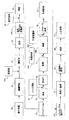
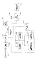
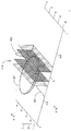
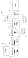
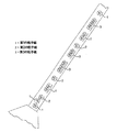
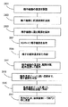
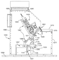
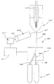
図1は、本発明の1つの例示的プロセスの工程の概要を提供するワークフロー図である。プロセスは、工程39にて、1以上の雄の動物(例えば、雄牛)からの正味の精液試料の収集で開始する。精液試料は、工程41にて、同定のために標識され、工程41Aにて緩衝剤と接触され、処理施設に移される。緩衝剤に加えて、例えば、エネルギー源、蛋白質源、抗生物質、および/または、酸化/還元反応を調節する組成物を含めた添加物を、工程41Aにて細胞内に、および/または細胞外に添加してもよい。任意の質制御テストを、工程43にて実施して、各試料の質(例えば、精子運動性)が、最終生成物が、最低限の質基準に見合う可能性が高いことを示すのに十分であることを確証してもよい。任意の洗浄工程は、工程47にて行うことができる。工程47Aにて、処理に使用される染色プロトコルは、様々な染色プロトコルを用いて、試料のアリコットを染色し、次いで各アリコットの仕分け性を分析して、その特定の試料に対する所望の染色プロトコルを同定することによって選択される。選択された染色プロトコルによる染色は、工程49にて、化学色素(例えば、DNA選択的蛍光色素)を含有する染色流体48を各試料に添加することによって行われる。染色する流体に加えて、工程48にて、例えば、エネルギー源、蛋白質源、抗生物質、および/または酸化/還元反応を調節する組成物を含む添加物を細胞内に、および/または細胞外に添加してもよい。試料は、工程51でインキュベートされて、精子による色素の取り込みを可能にする。次いで、試料は、工程53にて、フローサイトメトリーの試料導入デバイスに装填される。試料流体は、工程54にて、シース流体と一緒に、フローサイトメトリーに導入される。シース流体に加えて、工程54にて、例えば、エネルギー源、蛋白質源、抗生物質、および/または酸化/還元反応を調節する組成物を含む添加物を細胞内に、および/または細胞外に添加してもよい。工程55にて、フローサイトメーターは、下記されるように、特定のDNA特徴に従って、精子細胞を仕分ける。仕分けられた精子細胞が、工程57にて、フローサイトメーターの収集システムによって収集されると、それらは、工程58Aにて、収集流体または低温エキステンダーを含有する収集容器に添加される。収集流体に加えて、工程58Aにて、例えば、エネルギー源、蛋白質源、抗生物質、および/または酸化/還元反応を調節する組成物を含む添加物を細胞内に、および/または細胞外に添加してもよい。この時までに、精子細胞は、プロセスを通して添加された様々な流体によって希釈された溶液中にある。従って、所望のDNA特徴を有する精子細胞の集団は、工程58Bにて、商用人工授精における使用のために、濃縮される。低温エキステンダーは、工程58Cにて、濃縮された仕分けられた精子細胞に添加される。低温エキステンダーに加えて、例えば、エネルギー源、蛋白質源、抗生物質、および/または酸化/還元反応を制御する組成物を含む添加物を、工程58Cにて細胞内および/または細胞外に添加してもよい。次いで、精子細胞は、工程59にて、チューブ容器(畜産業では「ストロー」と呼ばれる)にパックし、工程61にて冷凍保存する。冷凍保存された精子は、工程63にて、液体窒素中に保存のためにパックされる。次いで、冷凍保存された精子は、工程65にて、商用流通システムを通して分配され、工程67にて動物畜産家に売られる。動物畜産家は、工程71にて、精子を使用して、雌の動物(例えば、ウシ)を人工的に受精する準備ができるまで、工程69にて、冷凍保存された精子を保存してもよい。下記で論議されるように、本発明の1つの具体例は、実質的に全工程を通しての温度調節を含む。同様に、規定された時間制限内の様々な工程の完了は、本発明のもう1つの具体例の1つの態様である。この全体的なプロセスは、本発明がどのように使用されるかの一例に過ぎず、後記の工程のいくつかを削除し、および/または他は加えることが可能であることが理解されるであろう。また、仕分けられた精子細胞は、マイクロインジェクションまたは他のインビトロ受精に使用して、その後、受容体の雌の動物に胚移植することもできる。
Summary FIG. 1 is a workflow diagram that provides an overview of the steps of one exemplary process of the present invention. The process begins at
本発明の進歩を取り入れた全プロセスの工程は、下記される。記載される特定のプロセスは、動物の精子(例えば、ウシの精子)を仕分けるという状況である一方、本発明の様々な態様は、精子のいずれのタイプ(ウマ、ブタ、および他)にもより一般的に、細胞のいずれのタイプにもさらにより一般的に、有機および無機、ラテックス粒子、磁気粒子、染色体、細胞下エレメント、プロトプラスト、および澱粉粒子を含む粒子のいずれのタイプにもよりさらに一般的に適用可能であることが理解されるだろう。これらの粒子は、一般的には、0.5ないし200ミクロンのサイズ範囲であるが、本発明の技術は、この範囲に制限されない。 The steps of the entire process incorporating the advancement of the invention are described below. While the particular process described is in the situation of sorting animal sperm (eg, bovine sperm), various aspects of the invention depend on any type of sperm (horse, pig, and others). In general, even more commonly for any type of cell, even more commonly for any type of particle, including organic and inorganic, latex particles, magnetic particles, chromosomes, subcellular elements, protoplasts, and starch particles Will be understood to be applicable. These particles are generally in the size range of 0.5 to 200 microns, but the technique of the present invention is not limited to this range.
試料収集および希釈
試料収集
仕分けられる精子試料は、ウシ、ウマ、ブタ、または他の哺乳動物源、または解凍された、冷凍保存されていた試料から新たに収集された試料であってもよい。さらに、試料は、単一の精液、同一の哺乳動物からの複数のプールされた精液、または2以上の動物からの複数のプールされた精液であってもよい。
Sample Collection and Dilution Sample Collection The sperm sample to be sorted may be a freshly collected sample from a bovine, equine, porcine, or other mammalian source, or a thawed, cryopreserved sample. Further, the sample may be a single semen, multiple pooled semen from the same mammal, or multiple pooled semen from two or more animals.
様々な収集方法が知られており、手袋法、人工腔の使用、および電気射精を含む。精子は、好ましくは、収集されるか、あるいは素早く断熱容器に移して、生理的温度(典型的には、約35℃ないし約39℃)からの速い温度変化を避ける。精液は、典型的には、種および特定の動物に応じて、約0.5ないし150億精子/ミリリットルを含有する。 Various collection methods are known and include glove techniques, use of artificial cavities, and electroejaculation. Sperm are preferably collected or quickly transferred to an insulated container to avoid rapid temperature changes from physiological temperatures (typically about 35 ° C. to about 39 ° C.). Semen typically contains about 0.5 to 15 billion sperm / milliliter, depending on the species and the particular animal.
収集の方法に拘わらず、アリコットを、精子試料から採取し、例えば精子濃度、精子運動性、精子進行的運動性、試料pH、精子膜統合性、および精子形態学といった様々な特徴につき評価することができる。このデータは、標準的かつよく知られた手順(例えば、Farrell et al. Theriogenology(1998) 49(4): 871-9; および米国特許第4,896,966号、同第4,896,967号参照)に従って、例えば、Hamilton-Thorn運動性アナライザー(IVOS)を用いた精子の検査によって得ることができる。 Regardless of the method of collection, aliquots are taken from sperm samples and evaluated for various characteristics such as sperm concentration, sperm motility, sperm progressive motility, sample pH, sperm membrane integrity, and sperm morphology. Can do. This data is obtained, for example, according to standard and well-known procedures (see, for example, Farrell et al. Theriogenology (1998) 49 (4): 871-9; and U.S. Pat. Nos. 4,896,966, 4,896,967). -Can be obtained by examination of sperm using Thorn motility analyzer (IVOS).
希釈
精子試料を、緩衝剤と(固体または溶液の形態で)組み合わせて、精子懸濁液を形成してもよい。なかでも、緩衝剤は、pHまたは浸透圧の有意な変化に対して、懸濁液を緩衝することによって、精子生存性を高めることができる。一般的には、緩衝剤は、細胞に対して無毒で、細胞を染色するのに使用される色素と適合性がある。例示的な緩衝剤は、リン酸塩、二リン酸塩、クエン酸塩、酢酸塩、乳酸塩、およびその組合せを含む。現在好ましい緩衝剤は、TCA、TEST、クエン酸ナトリウム、HEPES、TL、TES、クエン酸一水和物、HEPEST(Gradipore, St. Louis, MO)、PBS(Johnson et al., Gamete Research, 17:203-212(1987))、およびダルベッコPBS(Invitrogen Corp., Carlsbad, CA)を含む。
Diluted sperm samples may be combined with a buffer (in the form of a solid or solution) to form a sperm suspension. Among other things, buffering agents can enhance sperm viability by buffering the suspension against significant changes in pH or osmotic pressure. In general, the buffer is non-toxic to the cell and is compatible with the dye used to stain the cell. Exemplary buffering agents include phosphate, diphosphate, citrate, acetate, lactate, and combinations thereof. Currently preferred buffering agents are TCA, TEST, sodium citrate, HEPES, TL, TES, citric acid monohydrate, HEPEST (Gradipore, St. Louis, MO), PBS (Johnson et al., Gamete Research, 17: 203-212 (1987)), and Dulbecco's PBS (Invitrogen Corp., Carlsbad, CA).
1以上の緩衝剤は、下記のように、一緒にまたは添加剤と組み合わされて、緩衝液を形成してもよく、該緩衝液は、精子試料と組み合わされて、精子懸濁液を形成する。また、緩衝液は、下記でより詳細に記載されるように、1以上の添加剤を含有してもよい。例示的な緩衝液は、表Iに記載される。好ましい緩衝液は、約7.0のpHの水中の3%TRIS塩基、2%クエン酸一水和物、および1%果糖(w/v)を含む溶液、表IにおいてTCA #1と指定された溶液、表IにおいてTCA #2と指定された溶液を含む。
One or more buffers may be combined together or combined with an additive as described below to form a buffer, which is combined with a sperm sample to form a sperm suspension. . The buffer may also contain one or more additives, as described in more detail below. Exemplary buffers are listed in Table I. A preferred buffer is a solution containing 3% TRIS base, 2% citric acid monohydrate, and 1% fructose (w / v) in water at a pH of about 7.0, a solution designated

別法として、精子は、代謝阻害剤と組み合わせて、阻害された精子懸濁液を形成してもよい。代謝阻害剤は、精子細胞に、哺乳動物の副睾丸または精巣上体管の流体環境を刺激することによって、例えば雄牛のような哺乳動物の副睾丸の精子細胞を模倣させる。そのような阻害剤は、精子の運動性および代謝活性を減少させるかあるいは阻害するだろう。このクラスの例示的な阻害剤は、例えばSalisbury & Graves, J. Reprod. Fertil., 6:351-359(1963)記載のもののような炭酸系阻害剤を含む。このタイプの好ましい阻害剤は、NaHCO3、KHCO3、およびC6H8O7・H2Oを含む。このタイプのより好ましい阻害剤は、0.204g NaHCO3、0.433g KHCO3、および0.473g C6H8O7・H2O/25mLの精製水(水中に0.097モル/LのNaHCO3, 0.173モル/LのKHCO3, 0.090モル/L C6H8O7・H2O)を含む。 Alternatively, sperm may be combined with a metabolic inhibitor to form an inhibited sperm suspension. Metabolic inhibitors cause sperm cells to mimic sperm cells of a mammalian accessory testicle, such as a bull, by stimulating the fluid environment of the mammalian accessory testicle or epididymal duct. Such inhibitors would reduce or inhibit sperm motility and metabolic activity. Exemplary inhibitors of this class include carbonic acid inhibitors such as those described, for example, in Salisbury & Graves, J. Reprod. Fertil., 6: 351-359 (1963). Preferred inhibitors of this type include NaHCO 3 , KHCO 3 , and C 6 H 8 O 7 .H 2 O. More preferred inhibitors of this type are 0.204 g NaHCO 3 , 0.433 g KHCO 3 , and 0.473 g C 6 H 8 O 7 .H 2 O / 25 mL purified water (0.097 mol / L NaHCO 3 , 0.173 mol in water / L KHCO 3 , 0.090 mol / LC 6 H 8 O 7 .H 2 O).
緩衝剤に加えて、精子懸濁液は、一連の添加剤を含有して、精子生存性または運動性を高めてもよい。例示的な添加剤は、エネルギー源、蛋白質源、抗生物質、および酸化/還元反応を制御する組成物を細胞内および/または細胞外に含む。1以上のこれらの添加剤は、精子懸濁液の形成前に、緩衝剤または緩衝液に導入されてもよく、あるいは、別法として、精子懸濁液に別々に導入されてもよい。 In addition to the buffer, the sperm suspension may contain a series of additives to enhance sperm viability or motility. Exemplary additives include intracellular and / or extracellular sources of energy, protein sources, antibiotics, and compositions that control oxidation / reduction reactions. One or more of these additives may be introduced into the buffer or buffer prior to formation of the sperm suspension, or alternatively may be introduced separately into the sperm suspension.
1以上のエネルギー源を添加して、精子細胞が、細胞内リン脂質および他の細胞成分を酸化するのを阻害することができる。例示的なエネルギー源は、果糖、グルコース、ガラクトースおよびマンノースのような単糖、およびスクロース、ラクトース、マルトース、およびトレハロースのような二糖、ならびに他の多糖を含む。例えば、得られた精子懸濁液は、(複数の)エネルギー源の約1%(w/v)ないし約4%(w/v)を含み得る。含まれるならば、エネルギー源は、好ましくは、果糖であり、精子懸濁液は約2.5%(w/v)を含有する。 One or more energy sources can be added to inhibit sperm cells from oxidizing intracellular phospholipids and other cellular components. Exemplary energy sources include fructose, monosaccharides such as glucose, galactose and mannose, and disaccharides such as sucrose, lactose, maltose, and trehalose, and other polysaccharides. For example, the resulting sperm suspension may comprise about 1% (w / v) to about 4% (w / v) of the energy source (s). If included, the energy source is preferably fructose and the sperm suspension contains about 2.5% (w / v).
希釈ショックを最小化し、細胞に支持を提供し、懸濁を通して細胞を分散するために、蛋白質源が、緩衝剤、緩衝液、または精子懸濁液に含まれてもよい。例示的な蛋白質源は、卵黄、卵黄抽出物、牛乳(熱加熱均質化およびスキムを含む)、牛乳抽出物、大豆蛋白質、大豆蛋白質抽出物、血清アルブミン、ウシ血清アルブミン、ヒト血清代替補助剤、およびその組合せを含む。アルブミン、より具体的にはウシ血清アルブミン(BSA)が、好ましい蛋白質源である。例えば、もし含まれるならば、BSAは、約5.0%(w/v)未満、好ましくは約2%(w/v)未満、より好ましくは約1%(w/v)未満の量で、最も好ましくは約0.1%(w/v)の量で存在し得る。 A protein source may be included in the buffer, buffer, or sperm suspension to minimize dilution shock, provide support to the cells, and disperse the cells throughout the suspension. Exemplary protein sources include egg yolk, egg yolk extract, milk (including heat-heated homogenization and skim), milk extract, soy protein, soy protein extract, serum albumin, bovine serum albumin, human serum replacement supplement, And combinations thereof. Albumin, more specifically bovine serum albumin (BSA) is a preferred protein source. For example, if included, BSA is most often in an amount of less than about 5.0% (w / v), preferably less than about 2% (w / v), more preferably less than about 1% (w / v). Preferably it may be present in an amount of about 0.1% (w / v).
BSAのような蛋白質源のみの使用は、懸濁液中の精子細胞のパーセンテージで、受精能獲得のプロセスを開始することができる。このプロセスが、雌の生殖器官で起こるのが好ましい。従って、希釈の間、ならびに、引き続いての染色および仕分けの間、受精能獲得の開始を阻害するために、代替蛋白質源または蛋白質代替物が、精子懸濁液に含まれてもよい。代替蛋白質源または蛋白質代替物は、精子懸濁液中の細胞のより大きいパーセンテージでの受精能獲得の開始を阻害する能力に加えて、BSAのような典型的な蛋白質源の有利な効果を有する。代替蛋白質源の例は、ヒト血清代替物補助剤(SSS)(Irvine Scientific, Santa Ana, CA)およびコレステロールエンハンサーBSAを含み、一方、蛋白質代替物の例は、例えば、一般的に約30,000ないし約60,000の分子量を有する低いないし中程度の粘性ポリビニルアルコールのようなポリビニルアルコールを含む。一般的には、もし含まれるならば、これらの組成物は、緩衝剤または緩衝液の総アルブミン含有量が、一般的には約5.0%(w/v)を超えないBSAに関して、上記開示と同じ量で存在するだろう。 The use of only a protein source, such as BSA, can initiate the process of gaining fertility with the percentage of sperm cells in suspension. This process preferably occurs in the female reproductive organs. Thus, alternative protein sources or protein substitutes may be included in the sperm suspension to inhibit initiation of fertility during dilution and subsequent staining and sorting. Alternative protein sources or protein substitutes have the beneficial effects of typical protein sources such as BSA, in addition to their ability to inhibit the initiation of capacitation at a greater percentage of cells in the sperm suspension . Examples of alternative protein sources include human serum replacement supplement (SSS) (Irvine Scientific, Santa Ana, Calif.) And cholesterol enhancer BSA, while examples of protein alternatives generally include, for example, about 30,000 to about Polyvinyl alcohol such as low to moderate viscosity polyvinyl alcohol having a molecular weight of 60,000 is included. In general, if included, these compositions are generally the same as those disclosed above for BSA, where the total albumin content of the buffer or buffer generally does not exceed about 5.0% (w / v). Will be present in the same amount.
抗生物質を、細菌成長を阻害するために、精子懸濁液に添加してもよい。例示的な抗生物質は、例えば、チロシン、ゲンタマイシン、リンコマイシン、スペクチノマイシン、リンコ−スペクチン(登録商標)(塩酸リンコマイシン−スペクチノマイシン)、ペニシリン、ストレプトマイシン、チカルシリン、またはそのいずれかの組合せを含む。抗生物質は、精液が純物であるか、緩衝化されているか、例えば、本明細書中記載の添加剤のいずれかのようなさらなる物質を含有するかに拘わらず、約50μgないし約800μg/mlの精液の濃度で存在し得る。The Certified Semen Services(CSS)およびNational Association of Animal Breeders(NAAB)は、精子収集および使用に関する抗生物質の使用に関するガイドラインを公布している。 Antibiotics may be added to the sperm suspension to inhibit bacterial growth. Exemplary antibiotics include, for example, tyrosine, gentamicin, lincomycin, spectinomycin, linco-spectin® (lincomycin hydrochloride-spectinomycin), penicillin, streptomycin, ticarcillin, or any combination thereof. Including. Antibiotics are about 50 μg to about 800 μg / 800 μg / day regardless of whether the semen is pure, buffered, or contains additional substances such as, for example, any of the additives described herein. May be present at a concentration of ml semen. The Certified Semen Services (CSS) and the National Association of Animal Breeders (NAAB) have issued guidelines on the use of antibiotics for sperm collection and use.
酸化/還元反応を、細胞内および/または細胞外で制御する組成物も、精子懸濁液に含まれてもよい。そのような組成物は、例えば、精子生存性または進行的運動性を維持することによって、精子細胞に保護効果を提供することができる。そのような組成物の例は、例えば、ピルビン酸塩、ビタミンK、リポ酸、グルタチオン、フラビン、キノン、スーパーオキシドジスムターゼ(SOD)、およびSODミミックを含む。精子懸濁液中に含まれるならば、そのような組成物は、精子の健康に悪影響を及ぼさずに、保護効果を達成するのに十分な濃度で存在させることができる。例示的な濃度範囲は、使用される特定の組成物または懸濁液中の精子の濃度のような要因によって、約10μMないし約50mMを含む。例えば、ピルビン酸塩は、約1mMないし約50mM、好ましくは約2.5mMないし約40mM、より好ましくは約5mMないし25mM、さらにより好ましくは約10mMないし15mM、なおさらに好ましくは約15mM、最も好ましくは約10mMの濃度の精子懸濁液中に存在し得る。ビタミンKは、約1μMないし約100μM、好ましくは約10μMないし約100μM、より好ましくは約100μMの濃度の精子懸濁液中に存在させ得る。リポ酸は、約0.1mMないし約1mM、好ましくは約0.5mMないし約1mM、より好ましくは約1mMの濃度の精子懸濁液中に存在させ得る。 Compositions that control the oxidation / reduction reaction intracellularly and / or extracellularly may also be included in the sperm suspension. Such compositions can provide a protective effect to sperm cells, for example, by maintaining sperm viability or progressive motility. Examples of such compositions include, for example, pyruvate, vitamin K, lipoic acid, glutathione, flavin, quinone, superoxide dismutase (SOD), and SOD mimic. If included in a sperm suspension, such a composition can be present at a concentration sufficient to achieve a protective effect without adversely affecting sperm health. Exemplary concentration ranges include about 10 μM to about 50 mM, depending on factors such as the particular composition used or the concentration of sperm in the suspension. For example, pyruvate is about 1 mM to about 50 mM, preferably about 2.5 mM to about 40 mM, more preferably about 5 mM to 25 mM, even more preferably about 10 mM to 15 mM, still more preferably about 15 mM, most preferably about 15 mM. It can be present in a sperm suspension at a concentration of 10 mM. Vitamin K may be present in a sperm suspension at a concentration of about 1 μM to about 100 μM, preferably about 10 μM to about 100 μM, more preferably about 100 μM. Lipoic acid may be present in a sperm suspension at a concentration of about 0.1 mM to about 1 mM, preferably about 0.5 mM to about 1 mM, more preferably about 1 mM.
仕分けられる細胞の染色
一般的には、精子細胞は、精子細胞、緩衝剤、および色素を含む染色混合物を形成することによって染色することができる。精子細胞は、試料収集および希釈に関して上記したように、新たに得られた精液試料から、あるいは解凍された冷凍保存されていた精液試料から得ることができる。
Staining of sorted cells Generally, sperm cells can be stained by forming a staining mixture comprising sperm cells, buffer, and dye. Sperm cells can be obtained from freshly obtained semen samples or from thawed frozen stored semen samples as described above for sample collection and dilution.
もし精液試料が解凍された、事前に冷凍保存されていた試料であれば、精子は、好ましくは、染色の直前に解凍される。一般的には、冷凍された精子を含有するストローまたは他の冷凍保存容器は、温度が好ましくは精子細胞膜のガラス転移温度(つまり、約17℃)を上回るが、精子の健康に悪影響を及ぼすほどではない温度の水槽に入れることができる。例えば、冷凍された精子は、冷凍保存溶液を、約17℃ないし約40℃の温度に維持された水槽中に、約30秒ないし約90秒の期間、浸すことによって解凍することができる。 If the semen sample has been thawed and previously frozen and stored, the sperm is preferably thawed immediately prior to staining. In general, straws or other cryopreservation containers containing frozen sperm are preferably above the glass transition temperature of the sperm cell membrane (i.e. about 17 ° C), but have a negative impact on sperm health. Can be put in a water bath at a temperature not. For example, frozen sperm can be thawed by immersing the cryopreservation solution in a water bath maintained at a temperature of about 17 ° C. to about 40 ° C. for a period of about 30 seconds to about 90 seconds.
一旦入手されると、精子細胞は、純物の精子の形態で、例えば、試料収集および希釈に関して論議した精子懸濁液から得られる懸濁液の形態で、染色混合物に導入することができる。 Once obtained, sperm cells can be introduced into the staining mixture in the form of pure sperm, for example, in the form of a suspension obtained from the sperm suspension discussed for sample collection and dilution.
色素は、純物の固体または液体組成物の形態であってもよい。また、色素は、緩衝化されていない液体中に溶解または分散させて、色素溶液を形成することができる。別法として、色素は、色素および緩衝剤または精子細胞と生物学的に適合性のある緩衝液を含む色素懸濁液の形態であってもよい。例示的な緩衝剤および緩衝液の範囲は、試料収集および希釈に関して上記される。例えば、使用可能な緩衝剤の中には、約7.0のpHの水中に3% TRIS塩基、2% クエン酸一水和物、および1%果糖を含むTCA緩衝液、または0.204g NaHCO3、0.433g KHCO3、および0.473g C6H8O7・H2O/25mLの精製水(水中に0.097モル/LのNaHCO3, 0.173モル/LのKHCO3, 0.090モル/L C6H8O7・H2O)を含む炭酸系阻害剤溶液がある。すなわち、例えば、染色混合物は、純物精液を色素と組み合わせることによって形成することができる。別法として、染色混合物は、純物精液を緩衝剤または緩衝液および色素と組み合わせることによって形成することができる。さらに、染色混合物は、精子懸濁液を色素と組み合わせることによって形成することができる。 The dye may be in the form of a pure solid or liquid composition. The dye can also be dissolved or dispersed in an unbuffered liquid to form a dye solution. Alternatively, the dye may be in the form of a dye suspension comprising a dye and a buffer or a buffer that is biologically compatible with sperm cells. Exemplary buffer and buffer ranges are described above for sample collection and dilution. For example, some of the buffers that can be used are TCA buffer containing 3% TRIS base, 2% citric acid monohydrate, and 1% fructose in water at a pH of about 7.0, or 0.204 g NaHCO 3 , 0.433. g KHCO 3 , and 0.473 g C 6 H 8 O 7 .H 2 O / 25 mL of purified water (0.097 mol / L NaHCO 3 , 0.173 mol / L KHCO 3 , 0.090 mol / LC 6 H 8 O 7 in water There is a carbonic acid inhibitor solution containing H 2 O). That is, for example, a staining mixture can be formed by combining pure semen with a pigment. Alternatively, the staining mixture can be formed by combining pure semen with a buffer or buffer and dye. Furthermore, a staining mixture can be formed by combining a sperm suspension with a dye.
染色混合物は、米国特許第5,135,759号およびWO02/41906に既に記載されるように、1以上のUVまたは可視光線、DNA選択的色素を用いることによって形成することができる。例示的なUV光励起可能な選択的色素は、Hoechst 33342およびHoechst 33258を含み、これらの各々は、Sigma-Aldrich(St. Louis, MO)から商業的に入手可能である。例示的な可視光励起可能な色素は、Molecular Probes, Inc.(Eugene, OR)から商業的に入手可能なSYBR-14およびWO 02/41906記載のビスベンズイミド-BODIPY(登録商標)コンジュゲート6-{[3-((2Z)-2-{[1-(ジフルオロボリル)-3,5-ジメチル-1H-ピロール-2-イル]メチレン}-2H-ピロール-5-yl)プロパノイル]アミノ}-N-[3-(メチル{3-[({4-[6-(4-メチルピペラジン-1-イル)-1H,3'H-2,5'-ビベンズイミダゾール-2'-イル]フェノキシ}アセチル)アミノ]プロピル}アミノ)プロピル]ヘキサンアミド(「BBC」)を含む。これらの色素の各々は、単独でまたは組み合わせて使用されてもよく;別法として、他の細胞透過性UVおよび可視光励起可能な色素を、単独でまたは前記の色素と組み合わせて使用してもよく、但し、色素は、他所記載のように仕分けを可能にする濃度で使用される時、許容できない程度まで、精子細胞の生存性に悪影響を及ぼさない。 Staining mixtures can be formed by using one or more UV or visible light, DNA selective dyes, as already described in US Pat. No. 5,135,759 and WO02 / 41906. Exemplary UV photoexcitable selective dyes include Hoechst 33342 and Hoechst 33258, each of which is commercially available from Sigma-Aldrich (St. Louis, MO). Exemplary visible light excitable dyes are SYBR-14 commercially available from Molecular Probes, Inc. (Eugene, OR) and the bisbenzimide-BODIPY® conjugate 6-{[described in WO 02/41906. 3-((2Z) -2-{[1- (Difluoroboryl) -3,5-dimethyl-1H-pyrrol-2-yl] methylene} -2H-pyrrol-5-yl) propanoyl] amino} -N- [3- (Methyl {3-[({4- [6- (4-methylpiperazin-1-yl) -1H, 3'H-2,5'-bibenzimidazol-2'-yl] phenoxy} acetyl ) Amino] propyl} amino) propyl] hexanamide ("BBC"). Each of these dyes may be used alone or in combination; alternatively, other cell-permeable UV and visible light excitable dyes may be used alone or in combination with the dyes described above. However, the dye does not adversely affect sperm cell viability to an unacceptable extent when used at concentrations that allow sorting as described elsewhere.
染色混合物中のDNA選択的色素の好ましい濃度は、選択された色素に対する細胞の透過性、染色混合物の温度、染色が起こる時間の量、続いての仕分け工程で望まれる豊富化の程度を含む変数の範囲の関数である。一般的には、色素濃度は、好ましくは、実質的に精子生存性に有害な影響を与えずに、適度に短時間で所望の程度の染色を達成するのに十分である。例えば、染色混合物中のHoechst 33342、Hoechst 33258、SYBR-14、またはBBCの濃度は、一般的には、約0.1μMおよび約1.0Mの間、好ましくは約0.1μMないし約700μM、およびより好ましくは約100μMないし約200μMであろう。従って、一組の染色条件下で、Hoechst 33342の濃度は好ましくは約100μMである。もう一組の染色条件下で、Hoechst 33342の濃度は約150μMである。さらにもう一組の染色条件下で、濃度は好ましくは約200μMである。 The preferred concentration of the DNA selective dye in the staining mixture is a variable that includes the permeability of the cell to the selected dye, the temperature of the staining mixture, the amount of time that staining occurs, and the degree of enrichment desired in the subsequent sorting process. Is a function of the range. In general, the dye concentration is preferably sufficient to achieve the desired degree of staining in a reasonably short time without substantially detrimentally affecting sperm viability. For example, the concentration of Hoechst 33342, Hoechst 33258, SYBR-14, or BBC in the staining mixture is generally between about 0.1 μM and about 1.0 M, preferably about 0.1 μM to about 700 μM, and more preferably It will be about 100 μM to about 200 μM. Thus, under a set of staining conditions, the concentration of Hoechst 33342 is preferably about 100 μM. Under another set of staining conditions, the concentration of Hoechst 33342 is about 150 μM. Under yet another set of staining conditions, the concentration is preferably about 200 μM.
緩衝剤に加えて、他の添加剤を染色混合物に含んで、精子の生存性または運動性を高めてもよい;これらの添加剤は、精子源、色素源の一部として、または別々に、染色混合物に供されてもよい。そのような添加剤は、エネルギー源、抗生物質、細胞内および/または細胞外で酸化/還元反応を制御する組成物、および精漿を含み、これらの最初の3つは、試料収集および希釈に関して上記され、最後のものは収集流体に関して下記される。そのような添加剤は、それに従って、染色技術の間に添加されてもよい。 In addition to the buffer, other additives may be included in the staining mixture to increase sperm viability or motility; these additives may be used as part of the sperm source, part of the chromogen, or separately. It may be subjected to a staining mixture. Such additives include energy sources, antibiotics, compositions that control oxidation / reduction reactions within and / or cells, and seminal plasma, the first three of which relate to sample collection and dilution The last is described above with respect to the collected fluid. Such additives may be added accordingly during the dyeing technique accordingly.
特に、細胞内および/または細胞外で酸化/還元反応を制御する組成物を含むと、上昇した染色温度にて、上昇した色素濃度にて、増加した色素期間にて、あるいはそのいずれかの組合せにて、精子生存性を維持するのを助けることが観察されている。これらの組成物およびその試用の例は、緩衝剤および希釈剤に関して上記で論議される。そのような組成物は、それに従って、染色技術の間添加されてもよい。 In particular, including a composition that controls the oxidation / reduction reaction intracellularly and / or extracellularly, at elevated staining temperature, at elevated pigment concentration, at increased pigment duration, or any combination thereof Has been observed to help maintain sperm viability. Examples of these compositions and their trials are discussed above with respect to buffers and diluents. Such compositions may be added accordingly during the dyeing technique.
染色混合物は、温度の範囲のいずれかで維持されてもよく;典型的には、これは約4℃ないし約50℃の範囲内であろう。例えば、染色混合物は、「比較的低い」温度、つまり約4℃ないし約30℃の温度で維持されてもよく;この具体例において、温度は、好ましくは約20℃ないし約30℃であり、より好ましくは、約25℃ないし約30℃であり、最も好ましくは、約28℃である。別法として、染色混合物は、「中間」温度範囲、つまり約30℃ないし約39℃の温度内で維持され得る;この具体例において、温度は、好ましくは約34℃ないし約39℃であり、より好ましくは、約37℃である。加えて、染色混合物は、「比較的高い」温度範囲、つまり約40℃ないし約50℃内で維持され得る;この具体例において、温度は、好ましくは約40℃ないし約45℃であり、より好ましくは約40℃ないし約43℃であり、最も好ましくは約41℃である。好ましい温度の選択は、一般的に、例えば、使用される(複数の)色素への細胞の透過性、染色混合物中の(複数の)色素の濃度、細胞が染色混合物中で維持されるであろう時間の量、仕分け工程で望まれる豊富化の程度を含む変数の範囲によって決まる。 The staining mixture may be maintained in any of a range of temperatures; typically this will be in the range of about 4 ° C to about 50 ° C. For example, the staining mixture may be maintained at a “relatively low” temperature, ie, a temperature of about 4 ° C. to about 30 ° C .; in this embodiment, the temperature is preferably about 20 ° C. to about 30 ° C., More preferably, it is about 25 ° C to about 30 ° C, and most preferably about 28 ° C. Alternatively, the staining mixture can be maintained within an “intermediate” temperature range, ie, a temperature of about 30 ° C. to about 39 ° C .; in this embodiment, the temperature is preferably about 34 ° C. to about 39 ° C .; More preferably, it is about 37 ° C. In addition, the staining mixture may be maintained within a “relatively high” temperature range, ie, about 40 ° C. to about 50 ° C .; in this embodiment, the temperature is preferably about 40 ° C. to about 45 ° C., and more Preferably it is about 40 ° C to about 43 ° C, and most preferably about 41 ° C. The choice of preferred temperature will generally be, for example, the permeability of the cell to the dye (s) used, the concentration of the dye (s) in the staining mixture, the cells being maintained in the staining mixture It depends on the range of variables including the amount of waxing time and the degree of enrichment desired in the sorting process.
染色混合物中の精子細胞による色素の摂取は、所望の程度のDNA染色を得るのに十分な時間続けることが可能である。該時間は、典型的には、XおよびY染色体生成精子細胞が、2つの間の異なり測定可能な傾向強度に基づき仕分けられるように、色素が精子細胞のDNAに結合するのに十分な時間である。一般的に、これは約160分以下であり、好ましくは約90分未満であり、さらにより好ましくは約60分以下であり、最も好ましくは約5分ないし約40分であろう。 Dye uptake by sperm cells in the staining mixture can continue for a time sufficient to obtain the desired degree of DNA staining. The time is typically sufficient for the dye to bind to the sperm cell DNA so that the X and Y chromosome generating sperm cells are sorted based on the different measurable tendency intensities between the two. is there. Generally, this will be about 160 minutes or less, preferably less than about 90 minutes, even more preferably about 60 minutes or less, and most preferably about 5 minutes to about 40 minutes.
従って、1つの具体例において、染色混合物は、約100μMないし約200μMの濃度で、精子細胞および色素を含めて形成され、染色混合物は、約41℃の温度にて、ある時間、維持される。もう1つの具体例において、染色混合物は、さらに、約10mMの濃度でピルビン酸塩、約100μMの濃度でビタミンK、または約1mMの濃度でリポ酸を含む。 Thus, in one embodiment, the staining mixture is formed including sperm cells and dye at a concentration of about 100 μM to about 200 μM, and the staining mixture is maintained at a temperature of about 41 ° C. for a period of time. In another embodiment, the staining mixture further comprises pyruvate at a concentration of about 10 mM, vitamin K at a concentration of about 100 μM, or lipoic acid at a concentration of about 1 mM.
さらにもう1つの具体例において、染色混合物は、約100μMないし約200μMの濃度で精子細胞および色素を含めて形成され、染色混合物は、約28℃の温度にて、ある時間維持される。もう1つの具体例において、染色混合物は、約10mMの濃度でピルビン酸塩、約100μMの濃度でビタミンK、または約1mMの濃度でリポ酸を含む。 In yet another embodiment, the staining mixture is formed with sperm cells and dye at a concentration of about 100 μM to about 200 μM, and the staining mixture is maintained at a temperature of about 28 ° C. for a period of time. In another embodiment, the staining mixture comprises pyruvate at a concentration of about 10 mM, vitamin K at a concentration of about 100 μM, or lipoic acid at a concentration of about 1 mM.
さらにもう1つの例において、染色混合物は、精子細胞、0.204g NaHCO3、0.433g KHCO3、および0.473g C6H8O7・H2O/25mLの精製水(水中に、0.097モル/LのNaHCO3, 0.173モル/LのKHCO3, 0.090モル/L C6H8O7・H2O)を含む代謝阻害剤、および約100μMないし約200μMの濃度の色素を含めて形成され、染色混合物は、約28℃の温度にて、ある時間維持される。もう1つの具体例において、染色混合物は、約41℃の温度にて、ある時間維持される。 In yet another example, the staining mixture comprises sperm cells, 0.204 g NaHCO 3 , 0.433 g KHCO 3 , and 0.473 g C 6 H 8 O 7 .H 2 O / 25 mL purified water (0.097 mol / L in water). NaHCO 3 , 0.173 mol / L KHCO 3 , 0.090 mol / LC 6 H 8 O 7 · H 2 O), and a dye mixture formed and dyed at a concentration of about 100 μM to about 200 μM Is maintained at a temperature of about 28 ° C. for a period of time. In another embodiment, the staining mixture is maintained for a period of time at a temperature of about 41 ° C.
シース流体
精子細胞を仕分けるために、染色された細胞を、下記のように、フローサイトメーターのノズルへと、試料流体として導入する。プロセスの一部として、試料流体は、典型的には、シース流体によって囲まれる。シース流体は、試料流体中の精子細胞が、下記のように、単一のファイルラインへと引き出されることを可能にする。シース流体は、フローサイトメーターの収集システムによって、精子細胞と一緒に収集され、従って、精子細胞の仕分け後環境の一部を形成する。従って、シース流体が、シース流体による細胞の接触の際に、細胞に保護効果を供するのが望ましい。
Sheath Fluid To sort sperm cells, the stained cells are introduced as sample fluid into the flow cytometer nozzle as described below. As part of the process, the sample fluid is typically surrounded by a sheath fluid. The sheath fluid allows sperm cells in the sample fluid to be drawn into a single file line as described below. The sheath fluid is collected together with the sperm cells by the flow cytometer collection system, thus forming part of the post-sorting environment of the sperm cells. Therefore, it is desirable that the sheath fluid provides a protective effect to the cells when the cells are contacted by the sheath fluid.
シース流体は、一般的には、緩衝剤または緩衝液を含む。シース流体で使用され得る緩衝剤および緩衝液の例ならびにその実例的濃度を、試料収集および希釈に関して開示する。特定の具体例において、シース流体は、約7.0のpHの水中に0.96%ダルベッコのリン酸緩衝生理食塩水(w/v)、0.1% BSA(w/v)を含む。 The sheath fluid generally includes a buffer or buffer. Examples of buffers and buffers that can be used in the sheath fluid and their illustrative concentrations are disclosed for sample collection and dilution. In certain embodiments, the sheath fluid comprises 0.96% Dulbecco's phosphate buffered saline (w / v), 0.1% BSA (w / v) in water at a pH of about 7.0.
所望により、シース流体は、精子生存性または運動性に益するある範囲の添加剤を含有してもよい。例えば、そのような添加剤は、エネルギー源、蛋白質源、細胞内および/または細胞外で酸化/還元反応を制御する組成物、代替蛋白質源、およびポリビニルアルコールを含む。これらの添加剤、およびその例の各々は、試料収集および希釈に関して上記で論議されている。そのような添加剤は、それに従って、シース流体に添加されてもよい。 If desired, the sheath fluid may contain a range of additives that benefit sperm viability or motility. For example, such additives include energy sources, protein sources, compositions that control oxidation / reduction reactions within and / or cells, alternative protein sources, and polyvinyl alcohol. Each of these additives, and examples thereof, are discussed above with respect to sample collection and dilution. Such additives may be added to the sheath fluid accordingly.
シース流体は、所望により、仕分け工程前に濾過してもよい。非溶解性粒状物のようなシース流体中に存在し得る汚染物質は、仕分けと干渉し得る。従って、シース流体は、フローサイトメーターへの導入前に濾過してもよい。そのようなフィルターおよびそれを使用する方法は、当該分野でよく知られる。一般的に、フィルターは、約0.1ミクロンないし約0.5ミクロン、好ましくは約0.2ミクロンないし約0.3ミクロンであり、より好ましくは約0.2ミクロンの膜である。 The sheath fluid may be filtered prior to the sorting process if desired. Contaminants that may be present in the sheath fluid, such as non-dissolvable particulates, can interfere with sorting. Thus, the sheath fluid may be filtered prior to introduction into the flow cytometer. Such filters and methods of using them are well known in the art. Generally, the filter is a membrane of about 0.1 microns to about 0.5 microns, preferably about 0.2 microns to about 0.3 microns, and more preferably about 0.2 microns.
染色された細胞は、染色後のいずれの時点においてもシース流体に導入することができる。典型的には、試料流体中の染色された細胞の流れは、フローサイトメーターのノズル内のシース流体の流れに注入される。下記でより詳細に論議されるように、最初、流体の層流のため、試料流体およびシース流体の接触は実質的にはない。試料流体およびシース流体は、試料流体中の粒子(例えば、染色された精子細胞)が分析された後まで、実質的に別個の流れとして残ることが望ましい。しかしながら、ある時点で、試料流体のシース流体および細胞はもう一方と接触する。例えば、液滴仕分けフローサイトメーター(下記で論議される)において、シース流体および試料流体は、液滴が問い合わせ位置の下流で形成される時に、もう一方と接触し始める。 Stained cells can be introduced into the sheath fluid at any time after staining. Typically, the dyed cell flow in the sample fluid is injected into the sheath fluid flow in the flow cytometer nozzle. As discussed in more detail below, initially, there is substantially no contact between the sample fluid and the sheath fluid due to laminar flow of fluid. Desirably, the sample fluid and the sheath fluid remain as substantially separate streams until after the particles (eg, stained sperm cells) in the sample fluid are analyzed. However, at some point, the sample fluid sheath fluid and cells are in contact with the other. For example, in a droplet sorting flow cytometer (discussed below), the sheath fluid and sample fluid begin to contact the other when the droplet is formed downstream of the interrogation location.
染色された細胞およびシース流体の導入時、染色された細胞およびシース流体の両方は、約4℃ないし約50℃の温度であってもよい。シース流体および染色された細胞は、同じ温度または、どちらかが他方よりも高い温度である異なる温度であってもよい。従って、1つの具体例において、染色された細胞およびシース流体の導入時、細胞およびシース流体は同じ温度である;例えば、約5℃ないし約8℃のような、例えば「比較的低い」温度;例えば、約25℃ないし約30℃のような「中間の」温度;または約40℃ないし約43℃のような、「比較的高い」温度。もう1つの具体例において、染色された細胞は、シース流体より高い温度であり、例えば、細胞は約40℃ないし約43℃であり、シース流体は、約室温または約5℃である。さらにもう1つの具体例において、染色された細胞は、シース流体より低い温度である。 Upon introduction of the stained cells and sheath fluid, both the stained cells and sheath fluid may be at a temperature of about 4 ° C to about 50 ° C. The sheath fluid and stained cells may be at the same temperature or at different temperatures, either higher than the other. Thus, in one embodiment, upon introduction of stained cells and sheath fluid, the cells and sheath fluid are at the same temperature; for example, “relatively low” temperatures, such as from about 5 ° C. to about 8 ° C .; For example, an “intermediate” temperature such as about 25 ° C. to about 30 ° C .; or a “relatively high” temperature such as about 40 ° C. to about 43 ° C. In another embodiment, the stained cells are at a higher temperature than the sheath fluid, eg, the cells are at about 40 ° C. to about 43 ° C., and the sheath fluid is at about room temperature or about 5 ° C. In yet another embodiment, the stained cells are at a lower temperature than the sheath fluid.
フローサイトメトリー
本発明の1つの具体例は、フローサイトメトリーにおいて本発明の技術を使用して、精子細胞を分析し仕分ける。図2および3を参照して、本発明のフローサイトメトリーシステムの1つの具体例は、その全体において、参照数字1によって示される。見掛け通り、フローサイトメトリーシステム1は、選択された特徴に従って、精子細胞のような粒子を分類し仕分けるのに有用である。一般的に、システム1は、仕分けられる粒子を含有するキャリアー流体17の供給3、シース流体19の供給7、9と示される仕分け能力を有するフローサイトメトリー装置、および圧力下で、それぞれの供給3、7から担体17およびシース流体19をフローサイトメトリー装置9に送達するための流体送達システム15を含む。フローサイトメトリー装置9は、担体17およびシース19流体を受け取るように、流体17、19を組合せ、圧縮された流体21の流れを作るように、電磁放射線25(例えば、UVレーザー光)のフォーカスされたビームを通って粒子を運ぶ流れ21を方向付けるように、およびフォーカスされたビームを通過する粒子によって発光された電磁放射線31(例えば、蛍光)を分析するように適合される。また、装置9は、評価される粒子を含有する液滴33に流れ21を壊し、液滴33中に含有された粒子の1以上の特徴に従って、前記測定に基づき、液滴33を仕分けるように機能する。本発明を使用して、いずれのタイプの粒子も分析し、好ましくは仕分けることができる一方で、それは細胞の1以上の所望の特徴(例えば、サイズ、DNA含有量、形状、密度、遺伝子配列等)に従って、細胞を仕分けるのに特に適用を有する。本発明は、下記でより詳細に論議されるように、インビボまたはインビトロ人工授精のための動物生産業による商用使用のために、動物の精子細胞を仕分けるのに特に適している。
Flow Cytometry One embodiment of the present invention uses the techniques of the present invention in flow cytometry to analyze and sort sperm cells. With reference to FIGS. 2 and 3, one embodiment of the flow cytometry system of the present invention is indicated generally by the
シングルチャネル仕分け装置および方法
フローサイトメトリー装置
図3で示されるフローサイトメトリー装置9は、実質的にシングルファイル中の細胞および精子細胞の場合、実質的に記載されるであろう所望の配向の精子細胞の非対称性ヘッドとの圧力下で、ノズルオリフィス103を通って、粒子(例えば、染色された精子細胞)を含有する流体の流れ21を送達するための101と示されたノズルシステムを含む。慣用的なフローサイトメトリー液滴仕分けシステムでのように、ノズルオリフィス103から間隔を設けられた「液滴破壊」位置107にて、個々の細胞を含有する液滴33へと流れ21を破壊する流体の流れ21へ音響エネルギーを導入するために、ノズルオリフィス103に反対に提供される。また、システム1は、記載される具体例において、ノズルオリフィス103および液滴破壊位置107の間にある「問い合わせ」位置115にて、流体の流れ21に電磁放射線25(例えば、350-700nm UVまたは可視レーザー光)のビームをフォーカスするための109と示された光学システムを含む。従って、記載される具体例は、ジェットインエアーシステムである。他の具体例において、問い合わせ位置107は、ノズルオリフィス103内またはオリフィス103から上流であり得る。いずれにしても、細胞は問い合わせ位置107にて、光のビーム25を通過するように調整され、その結果、細胞中の化学染色(または他の報告媒体)が励起されて、ビーム25(例えば、もし照明光25が、約350ないし370nmの波長を有するなら、蛍光発光31は約460nmの波長を有し得る)のものと異なる波長を有する蛍光発光31が生じる。光検出器117は、これらの発光31を検出し、処理され、精子細胞のX/Y染色体の含有量のような選択された特徴に従って、細胞を分類するのに使用される電子シグナルへとそれらを変換するように操作可能である。さらに、フローサイトメトリー装置9は、液滴33中に含有された細胞の分類に従って、異なる群または集団(例えば、2つの集団123、125)に、液滴33を仕分けるための119と示された仕分けシステムおよび液滴33を収集し、異なる集団123、125の隔離を維持するための2201(図2)と示された収集システムを含む。
Single Channel Sorting Device and Method Flow Cytometry Device The
システム1の操作は、記載される様式で、システム1の要素の様々な機能を制御するマイクロプロセッサーまたは他のデジタルまたはアナログ制御および/またはプロセッサー、またはその組合せのようなプロセッサー131によって制御される。また、有意義なことに、プロセッサー131は、粒子分析情報に応答して、選択された制御および粒子の仕分けられた集団のうちの1つの所望の純度、1以上の他の集団中の所望の粒子の量(またはパーセンテージ)と比較した集団のうちの1つの所望の粒子の許容される量(またパーセンテージ)を含めた異なるパラメーター、および後記で論議される他のパラメーターを含む仕分け方法に基づき、システム1のアウトプットを制御する。
The operation of
システム1の様々な要素は、下記に詳細に記載される。
The various elements of the
ノズルシステム
図4および5を参照して、ノズルシステム101は、1つの例示的具体例において、それを通る中心縦内径135を有する略円筒型フローボディー133、および漏斗形状ノズルボディー139を有するフローボディー133上のノズル137を含む。通路141は、フローボディー133の内径135と同軸のノズルボディー139を通って延び、ノズル137の前端にて、前記のノズルオリフィス103で終わる。ノズルボディー139は、フローボディー133の前端にて、螺合突起またはスタッド149を螺合可能に受け取って、ノズル137をフローボディー133に取り外し可能に接続するために、後端にて、内方螺合穴ぐり145を有し、ここに該接続は、O-リングシール155によってシールされる。ノズルは、他の方法でフローボディーに取り外し可能に接続されるか、あるいは別法として、部分が1片として統合し形成することができることが理解されるだろう。
Nozzle System Referring to FIGS. 4 and 5, a
フローボディー133の内径135に同軸で置かれた導管157の手段によって、粒子はノズル137に送達される。導管157の外径は、輪形隙間が導管157周りに形成されるように、内径135の内径未満である。1つの特定の具体例において、ノズル137の後部の穴ぐり145へと延びる前部を有する管状針である。導管157の後端は、キャリアー流体15(例えば、精子細胞を含有する染色混合物)の導管157への送達のために、流体送達システム15に接続される。導管157の周りの輪形隙間167は、フローボディー133の半径内径173の手段によって、輪形隙間167へのシース流体19の送達のために、流体送達システム15に接続される。図3および5に示されるように、任意の第二の半径内径183は、ノズル137へのさらなるシース流体19の供給のために、もう1つのライン(図示せず)に輪形隙間167を接続するフローボディー133において提供され得る。
The particles are delivered to the
慣用的なフローサイトメトリーシステムにおけるように、シース流体19は、導管157を取り囲む輪形隙間167に導入される。導管157のチップを流れる時のシース流体19の速度は、導管157を出て行くキャリアー流体17の速度よりずっと高く、そこに含有されるキャリアー流体17および細胞(例えば、精子細胞)は、ノズル137のオリフィス103に向かって、シース流体19によって加速される。この加速は、光学システム109による別の分析のための単一ファイル配置において、細胞を間隔を開けて置くように機能する。シース流体19はキャリアー流体17を取り囲み、その結果、キャリアー流体17の中心コア189を有する流体の流れ21および中心コア189を取り囲むシース流体19の外側の同軸シース191が生じる(図6参照)。フローサイトメトリーの当業者によって理解されるように、中心コア189の層流および水力学的フォーカシングは、ノズル137中でシース19およびキャリアー流体17の少しの混合で、コア189に粒子を制限する傾向がある。さらに、液滴33が破壊位置107にて形成される時まで、流れ21がノズルシステム101を通るように、中心コア189はシース191内で実質的に無傷のままである。同軸流れのこのタイプは、分析される粒子が流れの比較的狭いコア189内に制限されるため、フローサイトメトリーに特に適している。結果として、流れ21の中心またはコア189上にフォーカスされた光25のビームは、実質的に一時に1つずつ分析することができるように、粒子を照らすだろう。十分に狭い直径内にコア189を制限することによって、コア流体189において、より均一な粒子の照明を得ることができる。良い分析結果のため、粒子を含有するコアの直径は、望ましくは、7ないし20ミクロンの範囲内、より望ましくは7ないし14ミクロンの範囲内であるべきである。コア流189の直径は、シース流体19の送達の速度に対してキャリアー流体17の送達の速度を調整することによって、増加または減少することができる。
As in conventional flow cytometry systems,
細胞の向き
分析結果を最適化するため、光学システムからの光ビームを通過する時、非対称な形状を有する粒子が所望の向きにあることが望ましい。当業者に知られるように、対称な粒子からの蛍光発光は、異方性のである傾向がある(つまり、発光の強度は、全方向において均一でない)。本明細書中で使用されるように、用語「所望の向き」は、70%ないし100%、より望ましくは80%ないし100%の範囲、さらにより望ましくは90%ないし100%の範囲、最も望ましくは95%以上の正確性で処理システムが異なる特徴を有する細胞間を識別するのを可能にする向きを意味する。
In order to optimize cell orientation analysis results, it is desirable that particles having an asymmetric shape be in the desired orientation when passing through the light beam from the optical system. As known to those skilled in the art, fluorescence emission from symmetrical particles tends to be anisotropic (ie, the intensity of the emission is not uniform in all directions). As used herein, the term “desired orientation” refers to the range of 70% to 100%, more desirably in the range of 80% to 100%, even more desirably in the range of 90% to 100%, most desirably. Means an orientation that allows the processing system to distinguish between cells having different characteristics with an accuracy of more than 95%.
ポイントを説明するために、ウシ精子細胞201は、図6および7で示される。典型的には、細胞は、比較的平坦で広い対向面207および狭いエッジ209、細胞の着色DNAマスを含有するヘッド205の核213、および有効な受精に必要な運動性を供するヘッド205から延びるテイル215を有する。平均的なウシ精子細胞201は、約8μmのヘッドの長さ219、約4μmのヘッドの幅221、ヘッドの前から約100μmのテイルの端までの全長223を有する。平均的なウシ精子細胞201において、核213は、ヘッド容量のほとんどを占有し、精子ヘッド205よりわずかに小さいだけである。従って、核の長さ217は、長さ約8μmであるヘッドの長さ219とほぼ同等である。ウシにおいて、精子細胞201のX/Y染色体は、ヘッド205の縦中線または赤道211または中心の下およびすぐ隣の核225(図6)の領域に局所化されることが観察されている。より詳細には、この赤道直下付近の領域225は、核213の下半分(テイル215に向かって)上の核の長さ217の約20%以下、よりさらに詳細には核213の下半分上の核の長さ217の約10-15%以下、さらにより詳細には核213の赤道211下約1.0-1.5μm以下延びる。
To illustrate the point,
精子細胞が、励起ビーム25を通過する時、細胞が実質的にシングルファイルであり、各細胞201が細胞間の向きの変動を減少させるように、実質的に同様に向いて、従って、細胞のより均一な測定を供するのが望ましい。また、細胞がXおよびY細胞の間に正確な識別を可能にする向きを有するのが望ましい。望ましくは、この向きは、精子細胞201の長さが、流れの流量227の方向(ヘッドが先(図6に示される)またはヘッドが後のいずれか)と大体並んでいて、細胞の狭いエッジ209よりはむしろ、図7に模式的に示されているように、光学系109からの光ビーム25が、一般に広い側で細胞の広い面207に当たる角エンベロープ229にヘッド205が入るように、精子細胞201のヘッド205がその縦軸上で回転される。好ましくは、所望の向きを規定するエンベロープ229は、流れ21を通って横方向に取った断面で見えるように、入る光ビーム25と略垂直な面Pに対してR1の角度範囲を通っての精子細胞201の回転によって生じる。範囲R1は、好ましくは0ないし90度であり、より好ましくは0ないし60度であり、さらにより好ましくは0ないし30度である。本発明のノズルは、90%以上までの正確性をもって、この所望の向きを達成するように操作可能である。
When sperm cells pass through the
精子向きの許容度(つまり、角度範囲R1によって規定されたエンベロープ229のサイズ)は、精子細胞からの蛍光発光31を収集するのに使用されるレンズの開口数に関する。図7に示される具体例において、例えば、光学システム109は、55度の立体角によって規定された蛍光発光31検出容量579を有する。精子ヘッド205の回転向きが、精子がビーム25を通る時にR1によって規定されたエンベロープ229の外側にある時、精子ヘッド205のエッジ209からの比較的より強い蛍光発光31は光学システム109によって収集され、プロセッサー131が蛍光発光31の強度を精子細胞201のX/Y染色体含有量と相関させることを防ぐ。しかしながら、問い合わせ位置115を通過する時に、精子ヘッド205の回転向きがエンベロープ229内にある限り、光学システム109は精子ヘッド205の狭いエッジ209からの比較的より強い蛍光発光31を収集しない。従って、図7に示される具体例において、精子ヘッド205の狭いエッジ209が角度R1内に制限される限り、精子細胞の向きは、比較的より強いエッジ蛍光発光の収集を生じない。収集容量579の立体角は、より小さい開口数を持つレンズを用いることによって減少させ、それにより角度R1およびあまり配向されていない精子の許容度を増加させることができる。しかしながら、これは、また、光検出器によって検出された発光31の強度を減少させることによって、蛍光発光31の測定に影響を及ぼし得る光学システム109によって収集され得るフォトンの数を減少させる。同様に、もし光学システム109が高い開口数を有する蛍光発光31を収集して、光検出器によって検出された蛍光発光のより強い強度を得るならば、精子向きに対する許容度は減少する。従って、本発明のシステムを設計する際、精子向きに対する許容度およびレンズ開口数の間の均衡をとることが必要である。最適な均衡は、システムの配向能力および光学感度によって決まるだろう。1つの望ましい具体例において、例えば、開口数0.65を有するレンズが使用される。
Sperm tolerance (ie, the size of
ノズル設計
1つの具体例において、図8および9に示されるように、穴ぐり145から下流のノズルボディー139の内部231は、ノズルオリフィス103に向かう下流方向の流体の流れ21の速度を次第に加速するための第1、第2および第3の軸方向にテーパーされた領域235、237、239を含む内面233を有する。前述のように、この加速は、単一ファイル形成を規定して、実質的に一度に1つの粒子が分析されるように、流れ21中の粒子(例えば、細胞)の間隔を設けるように機能する。これらの領域のうちの少なくとも2つ、および好ましくは全ての3つの235、237、239は、図9A-9Hおよび図9J-9Kに示されるように、ノズル137の縦軸247に対して直角での断面において略楕円形形状を有する。また、ノズルボディー139の内面233は、テーパーされておらず、第1の3つの領域235、237、239から下流および1つの具体例において、ノズルボディー139の前面の穴ぐり257に固定された別々のオリフィス部材255において形成されたノズルオリフィス103の直ぐ上流の第4の領域249を有する。1つの具体例において、第1の235および第2の237領域の略楕円断面形状は、実質的に同一の方向に配向されて、第1のねじりゾーン259を規定し、第2のねじりゾーン261を構成する第3の領域239の略楕円断面形状は、第1の235および第2の237領域の略楕円断面形状に対する角度(例えば、約90度)に配向される。配向は、ノズルボディー139の内面233が、流体の流れ21にねじり力を適用し、それによりノズルオリフィス103を通過する時に、前記の所望の向きに精子細胞を向かせる傾向があるようなものである。好ましくは、第1のねじりゾーン259は、3.0-4.5mm、好ましくは約3.6mmの軸の長さ273を有し、ゾーン259を構成する第1の235および第2の237テーパー領域は、大体同等の軸の長さ275、277(例えば、約1.8mm)を有する。第2のねじりゾーン261は、3.5-5.0mm、好ましくは約4.45mmの軸の長さ279を有する。第4の領域249は、好ましくは、形状が略円筒型である。第1の235、第2の237および第3の239領域の境界にある各略断面楕円形状A-D(図8)は、図8および下記の表1に示される例示的な寸法の長軸直径および短軸直径を有する。
Nozzle Design In one embodiment, as shown in FIGS. 8 and 9, the
上記の寸法は例示的であって、他の寸法および形状も適切であり得ることが理解されるであろう。機能的には、外径および内径の間の割合の変化、および領域の楕円形状の異なる向きは、各細胞201に対して作用する横力を作り、その縦軸に対して細胞201を回転させる傾向のあるねじり力271を適用して、その広い面207が第1のねじりゾーン259における短軸と並ぶように、細胞が緩やかに曲げられ(例えば、90度)て第2のねじりゾーン261の短軸と並ぶようにする。また、テーパー表面235、237、239の各々は、ノズル101を通って流れる流れ21(および細胞)を加速させるように働く。1つの具体例において、第1領域235および第3領域239においてより緩慢に増加し、第2の領域237においてより速く増加する。さらに一例としては、第1の領域235のテーパーは約11-14度の範囲であってよく;第2の領域237のテーパーは約42-48度の範囲であってよく;第3の領域239のテーパーは約8-12度の範囲であってよい。ノズルボディー139は、成型プラスチック(ABS)または金属のような適当な材料から形成される。
It will be appreciated that the above dimensions are exemplary and other dimensions and shapes may be suitable. Functionally, the change in proportion between the outer diameter and inner diameter, and the different orientation of the oval shape of the region create a lateral force acting on each
オリフィス部材255(図8)は、好ましくは、サファイアのような、加工できるか、さもなければ正確な寸法で形成され得る強固で摩耗耐性のある材料から形成される。オリフィス部材255自体は、1つの具体例において、直径が約0.92mmから約0.060mmまで減少する略円形断面の円錐上流表面309を有し、約0.54mmの軸の長さ317および約39度のテーパー角度を有する。また、オリフィス部材255は、約0.060mmの直径および約0.36mmの軸の長さ327を有する略円筒型下流表面315を有する。これらの寸法は例示的なだけであって、オリフィス部材255は他のサイズおよび形状を有し得ることが理解されるだろう。例えば、上流表面309の形状は、断面では略楕円形(長円形)であってもよく、ノズル137の下流末端のオリフィス103の直径は40ないし100ミクロン以上までの範囲であってもよい。オリフィス103のサイズは、ノズル101を出て行く細胞が、流れ21のコア189内の実質的に単一ファイル形成にあり、前述のように実質的に所望の向きにあることが望ましい。例えば、精子細胞の場合、下流末端で約60-62ミクロンの直径を有するオリフィス103が適当であることが分かっている。好ましくは、ノズルオリフィス103は、流れ21をさらに加速し、記載されるように、最適な細胞間隔、細胞の向きおよび液滴33形成のために、流れ21を形付け、大きさにするように働く。
Orifice member 255 (FIG. 8) is preferably formed from a strong, wear resistant material that can be machined or otherwise formed to precise dimensions, such as sapphire. The
ノズル137を出る時の細胞の速度は、シース流体19がノズルシステム101に導入される時の圧力を含めた様々な要因によって決まるだろう。20psiの圧力にて、細胞は、流れ21のコア189にて実質的に同様に配向された細胞を含有する略円筒型流れ21として、約16.6m/sの速度にて、上記具体例のノズルオリフィス103を出て行くであろう。30psiのシース圧にて、細胞速度は約20.3m/sであろう。異なるシース流体19圧にて、流れ21の速度は変動するだろう。
The velocity of the cells as they exit the
コア流のねじりゾーンへの導入
粒子の改善された向きは、粒子がノズルの中心からズレている位置にありつつ、粒子がノズルによって生じる水力学的配向力に付されるように、その少なくとも一部がノズルの中心からズレた流路に沿って、配向させるべき粒子(例えば、精子細胞)を含むコア流189を向けるように、配向ノズルを通る流体流れ21の流動を変化させることによって配向させることができる。コア流189をオフセット流路に沿って向けることは、従来のノズル(つまり、いずれのねじりゾーンも有さないもの)における粒子の配向を改善し得る。多くのノズルにおいて、ノズルの縦軸から移動しているため、所与の位置はノズルの中心からズレていると決定することができる。また、流体の流れが通って流れるノズルの断面積の幾何学的中心から移動されているため、特定の位置がノズルの中心からズレていると認識することができる。
Introduction of the core flow into the torsion zone The improved orientation of the particles is at least one so that the particles are subjected to the hydrodynamic orientation force produced by the nozzle while the particles are offset from the center of the nozzle. Orientation by altering the flow of
多くの技術を使用して、コア流189を、ノズルの中心からズレた流路に沿って向けることができる。例えば、配向バッフルはノズルに置かれて、コア流をノズルの一側面へ偏向することができる。同様に、試料粒子を含有するコア流189を導入するための導管157は、ノズルの従来の中心からオフセット位置へと移転されてもよい。さらに、オフセット試料導入導管157は、配向バッフルと併せて使用され得ることが考えられる。配向バッフルの使用およびオフセット試料導入導管の使用の例示的な具体例は下記で論議される。
Many techniques can be used to direct the
配向バッフルおよび/またはオフセット試料導入導管157の使用によって達成される粒子(例えば、精子細胞)の改善された配向は多くの要因によるものであり得る。一要因は、コア流189の偏向および/または断面流量範囲のサイズおよび形状の変化が、非対称の粒子を配向する傾向のある流体力の適用を招くことである。(Kachel, et al., Histochemistry and Cytochemistry, 25(7): 774-80(1977))。もう1つの要因は、非対称の粒子(特に精子細胞)が、固体表面近くで、流体の流れ中を流れるように配向する傾向があることが分かっていることである。従って、ノズルの内面またはバッフル表面近くにあるようにコア流189を方向付けることによって、粒子の改善された配向を得ることができる。さらに、バッフルおよび/またはオフセット試料導入導管を、さらなる配向する力(例えば、ねじり力)を非対称の粒子に適用する配向ノズルと併せて使用することができる。その場合、配向されるべき粒子が1以上のねじりゾーンによって生じるねじり力に付されつつ、該粒子を含有するコア流が、ノズルの中心からズレている流路に沿って流れるように、流体の流れを方向付けるように操作可能である。
The improved orientation of the particles (eg, sperm cells) achieved through the use of orientation baffles and / or offset
配向バッフル
図10-13は、上記の配向ノズル137に位置する2001と示された1つの例示的な配向バッフルを示す。しかしながら、バッフル2001は、本発明の範囲から逸脱することなしに、配向しないノズルを含む異なるノズルと併用することができる。バッフル2001はオリフィス103から上流および試料注入針157から下流のノズルに位置する。図14および15を参照すると、バッフルは、バッフルホルダー2005によって所定位置に保持されたバッフルプレート2003を含む。示された具体例において、バッフルプレート2003は略L字型であり、実質的に剛直で、耐久性の耐食材料(例えば、ステンレス鋼)で構築される。L字型プレート2003は、望ましくは相互に実質的に垂直(例えば、垂直であることの約5度以内)である上流レッグ2007および下流レッグ2009を有する。図面において示される例示的な具体例において、L字型プレート2003の2つのレッグ2007、2009は、ノズル137(図11)の縦軸2017に垂直なライン2015にて交差する。図14に示されるように、交差2015のラインは、また、バッフルホルダー2005の縦軸2057から短距離2033(例えば、約0.3mm)間隔を設けられる。L字型プレート2003の上流レッグ2007は、図15に示されるように、ノズル137の縦軸2017から離れた交差2015のラインから、途中ずっとバッフルホルダー2005の衛士まで延びる。従って、上流レッグ2007は、バッフルホルダー2005の形状に近似した曲面エッジで形成される。図14で示されるように、上流レッグ2007は、バッフルホルダー2005の縦軸2057に垂直から約15-25度の角度AA傾いている。L字型プレート2007の下流レッグ2009は、バッフルホルダー2005の縦軸2057の垂直から約60ないし80度の範囲にある角度BBにて、約2.0ないし2.5mmの距離2025だけ、2つのレッグ2007、2009の交差2015のラインから下流に延びる。
Orientation Baffle FIG. 10-13 shows one exemplary orientation baffle, designated 2001, located in the
バッフルホルダー2005は、図10-13に示されるように、ノズル137の内側に嵌合するような大きさ・形状とされる。バッフルホルダー2005は、好ましくは、成型可能な材料(例えば、ポリプロピレン)製であるが、バッフルホルダー2005は、本発明の範囲から逸脱せずに、他の材料から構築されていてもよい。図14および15において示されるように、例示的な具体例で使用されるバッフルホルダー2005は、一般的に、全体の長さ2027が約4.0-4.5mmの中空円筒殻として形作られる。バッフルホルダー2005は、約5-6mmの外径2029および約2.5-3.5mmの内径2031を持つ。もしバッフルホルダー2005が成型されるならば、抜きしろ(図示せず)を、(例えば、バッフルホルダーが、射出成型機械から容易に取り出せるように)ホルダー2005の表面に設けることができる。例示的なバッフルホルダー2005の上流端2035は、L字型プレート2003の上流レッグ2007と同じ角度AAで傾いた表面2037を有する。L字型プレート2003の上流レッグ2007は終端となり、バッフルホルダー2005の傾いた表面2037によって支持される。L字型プレート2003の下流レッグ2009のサイドエッジ2039(図15)は、バッフルホルダー2005に部分的に埋め込まれて(例えば、スロットで受け取られて)、下流レッグ2009がバッフルホルダー2005の一側面から他方にわたる位置に、バッフルプレート2003を維持する。例示的な具体例において、下流レッグ2009の下流エッジ2041は、バッフルホルダー2057の縦軸2057に略垂直な直線を形成する。下流レッグ2009の下流エッジ2041およびバッフルホルダー2005の柱面2051の間には、ギャップ2049(図14)がある。ギャップ2049は、L字型プレート2003のレッグ2007、2009によって規定された容量2053およびバッフルホルダー2003の内部円筒面2051およびノズル137の内部容量2055の残りの間の流体連絡を供する。
The
L字型プレート2003を上記の位置に保持するように、バッフルホルダー2005は、望ましくは、ノズル137の縦軸2017と整列したバッフルホルダー2005の縦軸2057を有するノズル内に置かれる。望ましくは、例示的なバッフルプレート2003は、プレート2003の2つのレッグ2007、2009の交差2015のラインが、図16に示されるように、楕円Dの長軸を通るライン2059に平行であるように、回転可能に向けられる。しかしながら、例示的なバッフル2001は、また、L字型プレート2003の2つのレッグ2007、2009の交差2015が、図17に示されるように、楕円Dの長軸を通るライン2059に垂直である時に上手く機能する。さらに、本発明の範囲から逸脱することなしに、バッフルはいずれかの回転向きを有し得る。図12に示されるように、例示的な具体例の試料注入針157は、望ましくは、バッフル2001の最上流部2035から約0.25-1.0mm上流の距離2061である。より望ましくは、試料注入針157は、バッフル2001の最上流部2035から約0.55-0.65mm上流である。
In order to hold the L-shaped
バッフルホルダー2005は、いずれかの数の方法で、ノズルに対して所望の位置で維持され得る。図14を参照して、バッフルホルダー2005の下流端2067は、ノズル137のさらに下流に篏合するように、段をつけられる。ホルダー2005の段をつけられた下流端2067は、円形状であり、ノズル137の楕円形の内面233で途切れる。従って、ノズル137の内面233およびバッフルホルダー2005の間の接触は、図13に示されるように、2つの点2069に制限される。一対のO-リング2071は、フローボディー133(図11-13)のノズル137および螺合突起149の間のバッフルホルダー2005辺りに位置し、漏れに対してノズルシステム101を閉じる。O-リング2071は、Viton(登録商標)、またはいずれかの他の同様の材料で出来ていてもよい。2つのO-リング2071は、ノズル137が螺合突起149に止められて、流体密封のシールを供するように、圧縮される。バッフルホルダー2005の長さ2027のため、単一のO-リングをノズル137およびフローボディー133の間の空間内に圧縮することができないので、2つのO-リング2071が例示的な具体例において使用される。いずれの数のO-リングまたは異なるタイプのシールも、本発明の範囲を逸脱することなく用いることができる。但し、O-リングの数、またはシールの他のタイプは、ノズルがフローボディー133に螺合した場合に液密シールとなるように選択されるものとする。これは、ノズル13、フローボディー133、バッフルホルダー2005、およびO-リング2071のサイズおよび形状ならびにシールのタイプを含めた多くの要因によって決まるだろう。また、O-リング2071は、所望の位置にバッフルホルダー2005を維持する。O-リング2071はバッフルホルダー2005辺りの空間を占拠し、それによりノズル137内のバッフルホルダー2005の左右の動きを制限する。また、O-リング2071およびバッフルホルダー2005の間の摩擦力は、バッフルホルダー2005の回転動作に抵抗する。
The
ノズル137が、図12に示されるように、フローボディー133上で閉められると、この具体例においてボスの形態であるフローボディー133からの螺合突起149の下流端2077は、バッフル2001の最上流部2035にほぼ等しい。結果として、バッフルホルダー2005は、フローボディー133(バッフルホルダー2005の上流端2035)および(バッフルホルダー2005の下流端2067の)ノズル137の内面233の間に、軸方向に捕らえられる。他の保持メカニズムを使用してもよい。図面において示される具体例において、螺合突起149の下流端のボス2079(図12)の内径は、バッフルホルダー2005の内径2031とほぼ同等である。
When the
当業者は、ノズルシステム101を通る流れが、流体が流れなければならない小断面積が、流れに低レイノルズ数を生じるため、バッフル2001にもかかわらず層流のままであることを認識するであろう。図11に示されるように、バッフルは、ノズル137の中心縦軸2017から離れて、ノズル137の内面233に向かって、コア流189およびシース流191を偏向する。1つの具体例において、コア流189が、第1の259および第2の261ねじりゾーンの間の移行の間を通る時、コア流189もノズル137の内面233の非常に近くを流れる。しかしながら、シース流体の流れ191の一部2081は、コア流189中の粒子は、ノズル137の内面233に実際に影響を与えたり、または接触しないように、コア流189およびノズル137の内面233の間に残る。ノズル137のさらに下流で、流体力は、ノズル137の中心に向かって(例えば、ノズル137の縦軸2017と並んで)、コア流189を押し戻す。
Those skilled in the art will recognize that the flow through the
図18A-18Eを参照して、バッフル2001は、ノズル137において、断面流量範囲の形状を変化させ、サイズを減少させる。(明確性のため、図18A-18Eは、バッフルから下流のいずれのノズル構造も示さない。図18A-18Eの各々における流量範囲は、明確性のため太字である)。バッフル2001(図18A)から上流で、断面流量範囲2087は、円形または楕円形である。バッフル2001の上流末端にて、流量範囲は、他の形状も適当であり得るが、バッフルプレート2003(図18B)のレッグ2007、2009の交差2015にて、円形状から略半円形状2089へと変化し始める。そこでは、断面流量範囲2089は、バッフルから上流の流量範囲2087より小さい。図18Cは、バッフルホルダー2005の一部から流体の流れとして流量範囲2091を示し、図18Dは、バッフルプレート2003の下流レッグ2009の下流端2041にて、さらに下流の流量範囲2093を示す。バッフルプレート2003の下流レッグ2009の角度方向のため、流量範囲2093は流量範囲2091よりいくらか大きいと観察されるであろう。バッフルプレート2003(図18E)から下流で、バッフルを通る流量範囲2094は、示された具体例において円形であるバッフルホルダー2005の内面2051の形状に対応する。(他の形状も適当であり得る)。バッフルホルダー2005から下流で、ノズル137のねじりゾーン259、261は、望ましくは、上記のようにねじり力を供する。
Referring to FIGS. 18A-18E, the
図11に示されるように、1以上の気泡2095は、L字型プレート2003の下流レッグ2009およびバッフルホルダー2005の間の容量2053中に捕獲され得ることが観察されている。さらに、気泡2095の一部は、下流レッグ2009のエッジ2041およびバッフルホルダー2005の間のギャップ2049を通って延びてもよい。従って、(複数の)気泡2095は、恐らくノズル137を通って流体の流れに影響を及ぼしながら、L字型プレート2003の下流レッグ2009の下流の断面流量範囲の一部を占有してもよい。例示的なバッフル2001は、(複数の)気泡2095あるなしで、上手く作用することが分かっている。従って、バッフルを使用して、本発明の範囲から逸脱せずに、いずれの気泡の関与もなくして、精子細胞を配向することができる。
As shown in FIG. 11, it has been observed that one or more bubbles 2095 can be trapped in the
2097と示されるもう1つの例示的な配向バッフルは、図19および20に示される。バッフル2097は、上記の配向ノズル137における平らで略半円形バッフルプレート2099を含む。バッフルプレート2099は、試料導入導管157の下流のノズル137に位置し、ノズル137の縦軸2017に略垂直である。バッフルプレート2099は、バッフルプレート2099の曲面エッジ2101およびノズル137の内面233の間に大きなギャップがないように、ノズル137の内面233の曲率に大体マッチする曲面エッジ2101を有する。また、試料導入導管157の外径2109と大体並ぶように、バッフルプレート2099は、ノズル137の縦軸2017を通って短距離延びる真っ直ぐなエッジ2103を有する。バッフルプレート2099は、前記L-字型バッフル2001に関連して記載されたO-リングシール2071と同様なO-リングシール2105と、ノズル137の内部に形成された環状ショルダーまたはシェルフ2107との間のバッフルプレート2099の圧縮に由来する摩擦によって所定の位置に保持される。図19に示されるように、配向バッフル2099は、分析される粒子を含有するコア流189が、その流路の一部に沿って、ノズル137の中心縦軸2017からズレるように、流体の流れを偏向することによって作用する。例えば、コア流189は、第1のねじりゾーン259、ならびに第2のねじりゾーン261の少なくとも一部を通って流れるように、ノズル137の縦軸2017からズレている流路に沿って向けることができる。結果的に、粒子(例えば、精子細胞)は、ノズル137の中心縦軸2017からズレている位置にあり、ねじりゾーン259、261によって生じたねじり力に付される。
Another exemplary orientation baffle, designated 2097, is shown in FIGS. The baffle 2097 includes a flat and substantially
当業者は、本発明の範囲から逸脱することなしに、実質的な変形が上記の例示的バッフル2001、2097に行われ得ることを認識するであろう。必要なのは、バッフルが、ノズルの内面に向かって、コア流189およびシース流191を偏向するように、またはコア189およびシース流191が、サイズおよび/または形状が変化する断面積を通って流れるように操作されることのみである。さらに、配向バッフル構造は、本発明の範囲から逸脱せずに、ノズルと統合的に形成されるか、あるいはノズルおよびフローボディーと統合的に形成され得ると理解される。
Those skilled in the art will recognize that substantial modifications may be made to the above
オフセット試料導入導管
コア流189は、ノズル137の中心のその従来の位置からズレた位置へと試料導入導管157を配置し直すことによって、ノズル137の中心縦軸2017からズレた流路に沿って方向付けられてもよい。例えば、図21は、ズレた試料導入導管157を有する例示的なズレた試料導入ノズルシステム2151を示す。特記しない限り、ノズルシステム2151は、図4および5に示されるように、ノズルシステム101と実質的に同一である。有意な差は、ノズルの縦軸2017と並ばないように、試料導入導管157がノズル137の中心から動かされていることである。従って、コア流189は、縦軸2017からズレた流路に沿って、配向ノズル137のねじりゾーン259、261へと向けられる。図21に示される例示的なノズルシステム2151は、上記の例示的な配向ノズル137を使用するが、ズレた試料導入導管157を、異なる配向ノズルまたは非配向ノズルと使用して、コア流189において粒子を向けることができると考えられる。
The offset sample introduction
ノズル取り付けおよび調整
フローボディー133およびノズル137は、331と示されたノズル取付具の手段によって選択された向きおよび位置に取り付けられる。1つの具体例(図22)において、取付具331は、各R、XおよびY軸339、341に沿ってフローボディー133およびノズル137の直線状調整を供する第1および第2直線ステージ333、337、およびフローボディー133およびノズル137の縦軸2017に対応するZ軸345の回りの回転調整を供する第3の回転ステージ343を含めた複数のステージを含む。これらのステージ333、337、343は、例えばNewport Corporation of Irvine CAから商業的に入手可能な、慣用的設計の適当なステージであってもよい。特に、第1の直線運動ステージ333は、フレーム349上に取り付けられた固定された第1のステージ部材(図示せず)、X軸339に沿って固定された第1のステージ部材上で滑らすことができる可動性の第1のステージ部材355、および選択されたX-軸位置に、可動性の第1のステージ355部材を正確に動かすための例えば、マイクロメーターといったアクチュエータ357を含む。第2の直線運動ステージ337は、可動性の第1のステージ部材355上に取り付けられた固定された第2のステージ部材359、Y軸341に沿って固定された第2のステージ部材359上で滑らすことができる可動性の第2のステージ部材361、および選択されたY-軸位置へ可動性の第2のステージ部材361を正確に動かすための例えば、マイクロメーターといったアクチュエータ363を含む。回転(第3の)ステージ343は、可動性の第2のステージ部材316、Z-軸345に対する回転のために、固定された第3のステージ部材365上に回転可能に取り付けられた可動性の第3のステージ部材371、およびZ-軸345に対する選択された角度位置に可動性の第3のステージ部材371を正確に回転するための例えば、マイクロメーターといったアクチュエータ373を含む。これらのステージ333、337 343によって供される三軸調整によって、ノズルオリフィス103を出て行くノズル137および流体の流れ21が、光学システム109に対して正確に置かれることが可能になる。Z-軸345に対するノズル137の回転は、図23に図式的に示されるように、ノズル137を出て行く流れ21が、ノズル137によって配向された細胞(例えば、精子細胞)を、光学システム109からの光ビーム25が細胞の所望の表面(例えば、精子ヘッド205の平坦な面207)上に落ちるであろう位置に持ってくるように、回転させることを可能にするため、特に有用である。他のノズル取付具が適当であり得る。例えば、4-軸ノズル取り付けシステムも使用し、X、YおよびZ軸に沿って直線調整およびZ軸に沿って回転調整を提供することができる。さらに、サーボまたはステッパーモーター制御されたマイクロトランスレーションステージ(例えば、Auburn, MichiganのPolytech PI, Inc.からの成分番号M-110.2DG)のような、自動並列特徴を有する1以上のステージを使用することが望ましいかもしれない。
Nozzle Mounting and Adjustment The
図36において模式的に示された1つの具体例において、例えば、ノズル137は、分析される細胞を含有する流れ21を略上向き方向に向けるように向けられる。流体の流れ21の方向および水平方向の間の角度377は、好ましくは5ないし85度の範囲、より好ましくは15ないし75度の範囲、さらにより好ましくは約30ないし65度、なおさらに好ましくは約45ないし60度、最も好ましくは約50ないし55度である。この配向は、ノズルシステム101中に閉じ込められたいずれの空気もすぐに除去される点で有利である。また、流体の流れ21の速度は、液滴33の収集前に重力下で、徐々に減少する。液滴33のより緩やかな減速は、精子細胞の場合、収集後に仕分けられた精子のより高い運動性を招くことができる分析される細胞に対してよりストレスが少ないと考えられる。もちろん、本発明の他の具体例において、ノズル101は、ジェットインエアーサイトメーターに対して慣用的であるように、オリフィス103を出て行く時、流体の流れ21が実質的に下向きの速度を有するように置かれる。
In one embodiment schematically illustrated in FIG. 36, for example,
所望により、フローボディー133およびノズル137のようなノズルシステム101の要素は、非反射性、非発光性材料(例えば、UV光線に付された時、光を発光しないくすんだ暗いペイントまたはエポキシ)で覆われて、シグナルノイズを引き起こすかもしれない、または光学システム109に対して他の有害な影響を有し得るこれらの要素133、137からのいずれかの反射されたおよび/または発光された光を減少する。
If desired, elements of
変換器および液滴形成
流体の流れ21にエネルギーを導入するための変換器105は、1つの具体例において、ノズルシステム101(図3〜5)のフローボディー133の回りに固定された焦電エレメント(図示せず)を含むカラー379を含む。変換器は、Beckman Coulter, Inc.から成分番号6858368として入手可能な慣用的設計である。ノズル137から距離dだけ下流にある液滴破壊位置107においてそれを破壊して液滴33とする周波数にて、エネルギーが流体の流れ21に送達できるように、変換器は音響エネルギーの適当な源への連結用のターミナル383を有する。フローサイトメトリーの当業者によって理解されるように、液滴形成の特徴は、次の方程式1によって支配される:
![]()
![]()
![]()
![]()
破壊センサー
図2を参照して、破壊センサー389を使用して、流れ21が遊離液滴33を形成し始める位置(例えば、破壊位置107)を決定することができる。破壊位置107は、流れ21粘度、流体の表面張力および変換器105の振動の幅を含めたいくつかの要因によって変動するであろう。破壊位置107をモニタリングすることによって、変換器105の振幅を変動させて、破壊位置107を所与の範囲内に維持し、各液滴33が破壊する時が、マイクロプロセッサー131によってより正確に予測できるようにする。これによって、流れ21の変化を選択的に制御することによって達成される液滴33の電荷をマイクロプロセッサー131が正確に制御することが可能になる。液滴33の電荷は、液滴33形成の直前の流れ21の電荷と同じであるため、マイクロプロセッサー131は、下記のように、流れ21を選択的に荷電することによって、液滴33の仕分けを制御する。
Break Sensor Referring to FIG. 2, a
一般的に、破壊センサーは、破壊位置にて液滴へと壊れる流体のいずれかの連続した流れと共に使用するためのものである。(図2の具体例において、破壊センサー389は、ノズル137および問い合わせ位置115から下流に位置する)。1つの例示的な破壊センサー389は、図25に図式的に示される。光源393は、流れ21の一側面に位置して、破壊位置107が維持されるであろう所与の範囲内に流れ21を照らす。流れ21の他の側面上に位置した線状フォトアレイ395は適合されて、流れ21に実質的に平行な軸に沿って配向される。結果として、フォトアレイ395は、液滴33を通過する光源393からの光を検出し、検出された光に対応するアウトプットシグナルを供する。
In general, a break sensor is for use with any continuous flow of fluid that breaks into droplets at the break location. (In the example of FIG. 2, the
アウトプットシグナルを処理して、破壊位置107の位置を決定する。例えば、アウトプットシグナルはデジタル化され、処理のためにプロセッサー131に供される。別法として、図25に示されるように、光源393は、LEDまたは可視スペクトルの近赤外部分を生じる他の源であってもよい。液滴33間の光通過は、レンズ401によって拡大され、フォトダイオード395の1線状アレイによって8に向けられる。各フォトダイオードは、作用する光強度に比例する電流を発生する。この電流は、8つの電流電圧オペアンプ回路405へ送られる。オペアンプからのアウトプット電圧は、8トラック/ホールド増幅器407にACカップリングされる。増幅器によって使用されるトラック/ホールドシグナル409は、変換器105から採取される。トラック/ホールド増幅器からのアウトプットは、マイクロプロセッサーユニット(MPU)391のA/D変換器411に送られる。MPU391によって計算されたデジタル値は、システム制御マイクロプロセッサー131に供されるであろう。参照テーブルおよび/またはアルゴリズムは、システム制御マイクロプロセッサー131によって使用されて、破壊位置107ドリフトおよび変換器105に対する電圧調整の間を変換する。別法として、MPU391からのアウトプットは、変換器105の振動の振幅の変化に対応する振幅を有するDC電圧のようなアナログシグナルであってもよい。dc電圧は、液滴変換器105を駆動する高電圧増幅器インプットに適用されて、振動の振幅を変化させることができる。従って、そのようなプロセッサー391は、フォトアレイ395からアウトプットシグナルを受け取り、破壊位置107の位置に対応する位置シグナルを供するための制御を構成する。そのようなプロセッサー391は、また、液滴33の破壊位置107の位置の指標であるアウトプットシグナルを受け取り、位置107の位置の関数として変換器105の作用を変化させるための制御を構成する。
The output signal is processed to determine the location of the
別法として、当業者によく知られるように、ビデオカメラおよびストロボを使用して、液滴破壊位置をモニターし制御することができる。従って、図26-27で示されるように、ビデオカメラシステム412およびストロボ413を、破壊位置107をモニターするために供してもよい。ストロボ413をマスク414A(例えば、小さなスリット形状の開口414Bを備えたカバー)の後ろに置いて、光学システム109に入るストロボ413によって生成される光の量を制限するのが望ましい(図27)。
Alternatively, the drop break location can be monitored and controlled using a video camera and strobe, as is well known to those skilled in the art. Accordingly, as shown in FIGS. 26-27, a
落射照明光学システム
光学システム109は、分析される細胞がスポットを通過するように、ビームスポットとして、流体の流れ21に電磁放射線25(例えば、レーザービーム)のビームをフォーカスするために調整される。他の波長を使用してもよいが、例えば約350-700nmの波長を有するスペクトルの可視または紫外線部分のレーザー光であってもよい。レーザー光の波長は、粒子を分析するのに使用される特定の蛍光色素を励起することが可能であるように選択することができる。もし光学システム109を使用して、例えばHoechst 33342で染色された精子細胞を分析するならば、波長は、約350-370nmの範囲であるように選択され得る。レーザーの電力アウトプットは、50および300mWの間を変動し得る。例えば、精子細胞は、200mWレーザーを用いて分析され得る。図28-34を参照して、システム109は、縦光学軸419を有する417と示された器具を含む落射照明システム415である。本明細書中で使用されるように、用語「落射照明」は、ビームスポットを通過する細胞からの蛍光発光の少なくともいくつかが、フォーカスされたビーム25と同じ軸に沿ってだが、反対方向に、光学器具を通って向けられる光学システムを意味する。システムのこのタイプは、前蛍光および側蛍光を検出し、2つ以上の光検出器を使用する慣用的なシステムと違って、唯1つの光検出器117を含めた、一組の光学のみが必要であるという点で有利である。しかしながら、落射照明システムが好ましいが、本発明の多くの態様が、使用される光学システムのタイプに拘わらず適用できることが理解されるであろう。
Epi-illumination optical system The
1つの具体例において、落射照明器具417は、複数の光学要素を支持する長方形のベース429を含む。これらの光学要素は、関連した寸法、焦点距離、およびパーツ数の具体的な例と共に下記される。当業者によって理解されるように、この情報は例示的なものであるだけであって、代替の光学要素を、本発明の範囲から逸脱することなしに使用することができる。
In one embodiment, the epi-
図28-34を参照して、光学要素は、レーザーまたはアークランプ435からの光の平行ビーム25を、例えば、ベース429から延びるダイクロイックチャンバー443の側壁441の開口439に取り付けられた調節レンズアセンブリ437を通って反射する反射フィルター431を含む。この特定の具体例において、調節レンズアセンブリ437は、止め輪445、減光フィルター447、円柱レンズ449、レンズホルダー455および薄ナット457を含む。円柱レンズ449は、ビーム225に一次元発散を導入し、好ましくは略楕円形である所望の断面形状459を有するようにビームを形付ける光学要素(下記される)に向かわせる。一例として、円筒型レンズ449は、16mmの焦点距離を有する平凸レンズであってもよい。ビーム拡大器(図示せず)は、所望により、器具417にインストールされて、楕円形ビームスポット459の形状に調整を加えることを可能にする。
Referring to FIGS. 28-34, the optical element includes an
反射フィルター431は、ビーム25がd器具417の光学に向けてフィルター431を反射することが可能なように、開口467を有するフォルターホルダー463の角張った面465上のクリップ461によって取り付けられる。ホルダー463は、ベース429およびダイクロイックチャンバー443に固定されたアウトリガ473に対するX-軸471に沿って動かすことが可能な線状ステージ469、適切な位置で、器具417にビーム25を反射するように、ホルダー463および反射フィルター431を正確に置くための適当な手段475(例えば、マイクロメーター)によって動かすことが可能なステージ469に固定される。ダイクロイックフィルター477は、チャンバー443に取り付けられたフレーム485上のクリップ479によって保持され、この特定の具体例において器具の縦の光学軸419に対応する軸489に沿って順方向487に形作られたビーム25を反射するように機能する。ビーム25は、流れ21の流れ227の方向に略垂直に延びる楕円の長軸を有する前記の略楕円形状459(図6)を持つビームスポットとして、流体の流れ21上のビーム25をフォーカスするフォーカスレンズアセンブリ491を通過する。各細胞がビームスポット459を通過する時、細胞中の蛍光染料(または他のレポーティング剤)は活性化されて、蛍光31(図23)を発光する。DNA選択的蛍光染料で染色された精子細胞の場合、記載されるように、X細胞はY細胞より多くのDNAを有し、より多くの蛍光染料を含み、細胞を識別し仕分けるための基準を供するY細胞(例えば、3.8%)より強いシグナルを発光する。1つの具体例において、フォーカスレンズアセンブリ491は、ダイクロイックチャンバー443の前壁505の開口503に取り付けられた顕微鏡アダプター501、フォーカスバレル507、一対のレンズ取り付けバレル509、およびレンズ511それ自体、成分番号41209としてOriel Corporationから入手可能な16mmの焦点距離を有する直径12.5mmの平凸レンズを含み、ならびに340-550nmの範囲の波長を有する光に対して反射防止的に覆われる。レンズ511は、石英ガラスであってもよい。また、無限−修正蛍光顕微鏡対物レンズのような他のフォーカスレンズも適当であり得る。フォーカスレンズアセンブリ491は、流れ21のコア189に楕円形状のビームスポット459をフォーカスするために、慣用的なテレスコーピングフォーカス調整515を有する。
The
ビームスポット459を通過する時に細胞によって発光される出て行く蛍光31は、入射レーザー光25とは異なる(ストークスシフトの法則のためより長い)。蛍光発光31のいくつかは、蛍光発光31を収集し平行にするフォーカスレンズ511を通る入射ビーム軸に沿って、逆方向513に伝達される。平行蛍光発光517は、レンズ511から、蛍光発光517を伝達するダイクロイックフィルター477に、逆方向に通過する。一例としては、ダイクロイックフィルター477は、成分番号XF2001, 400DCLPとして、Omega Opticalから入手可能なフィルターであってもよい。
The
光学システム415は、器具417の光学軸419に沿って、ダイクロイックフィルター477の後ろに置かれたフィルターシステム519を含む。1つの具体例において、フィルタリングシステム519は、ダイクロイックチャンバー443の後壁527の開口525に取り付けられたホルダー523中の発光フィルター521を含む。発光フィルター521は、ダイクロイックフィルター477を通って伝達されるいずれかのレーザー光散乱または他の所望の電磁放射線を弱める。一例としてであって、制限としてではなく、発光フィルター521は、成分番号XF3097として、Omega Opticalから入手可能であるように、408nmより大きい波長を有する光の90%以上を伝達するように適合された薄膜のロングパスフィルターであってもよい。整列薄膜アセンブリ529は、光学軸419に沿って、発光フィルターから後ろに間隔を設けられる。このアセンブリは、装置417の縦光学軸419に平行なべース429の縦方向に延びるレール533上で動かすことが可能なスライダー531、スライダー531に固定されたフィルターホルダー535、薄膜フィルター要素539、および器具417の光学軸419に対する角度543にて、薄膜フィルター要素539をフィルターホルダー535に固定するためのクリップ541を含む。薄膜フィルター要素539は、ダイクロイックフィルター477と同じ厚みを有し、器具417の光学軸419上に平行蛍光発光517を翻訳し直すように機能する。レール533の反対側上のベース429の平行スロット547を通って延びるファスナー545は、光学軸419に沿った所望の位置のベース429にスライダー531を固定する。整列薄膜アセンブリ529の後方に間隔を設けて、レール533上を摺動可能であって、適当なファスナー557によって選択位置に固定されたフレーム533に設置されたホルダーによって保持された非球面レンズ549がある。非球面レンズ549は、コリメートされた蛍光発光517を、一般に559で示される空間フィルターにフォーカスし、そのフィルターは分析すべき細胞以外の源からの反射または発光を濾過する。非球面レンズ549は、Oriel Corporationから入手可能なように、15mmの焦点距離を有する、例えば、直径が12.5mmの非球面レンズであってもよい。レンズ549は、好ましくは、可視の発光波長に対して反射防止被覆されるが、レーザー光散乱の伝達をさらに弱める材料(例えば、フリントガラス)でできている。
The
図34に示されるように、空間フィルター559は、1つの具体例において、装置417のベース429に取り付けられたフレーム563によって取り外し可能に保持された一対の開口プレート561を含む。プレート561の各々は、その中にスリット567、571を有し、1つのスリット567は、好ましくは略垂直で、他方の571は、好ましくは略水平で、配置は、スリット567、571が開口573を形成するように交差するようなものである。1つの具体例において、開口573は、形状が略長方形であり、100ミクロンの垂直寸法575および500ミクロンの水平寸法577を有する。開口573のサイズおよび形状は、収集容量579以外のいずれかの源から反射および光を除去するように機能する限り、変動し得る(または開口プレートを変更することによって調整さえされ得る)。開口プレート561を保持するフレーム563は、好ましくは、2つのパーツ、すなわち、ベース429のレール533上を摺動可能であって、ファスナー587によって選択位置に固定されたプレートホルダー583、および開口プレートをプレートホルダー583上の所定の位置に固定するバッキングメンバーを有する。
As shown in FIG. 34, the
1つの具体例において、空間フィルター559における開口573のより小さい(垂直)寸法575は、細胞を評価するための「スリットスキャニング」技術の使用を可能にするような大きさにされる(あるいは調整される)。この技術は、本明細書の「フォーカスされたビームスポット」セクションにより詳細に記載される。
In one embodiment, the smaller (vertical)
450と示される落射照明光学システムのもう1つの具体例は、図35に示される。この具体例は、記される以外は、図28-34に示される具体例と実質的に同じである。1つの有意な差は、ダイクロイックフィルター477が、照明ビーム25を(反射というよりむしろ)伝達し、蛍光発光31を(伝達というよりむしろ)反射する異なるダイクロイックフィルター451によって置き換えられるということである。また、蛍光発光31は、ダイクロイックフィルター451によって、伝達されるというよりむしろ反射されるため、落射照明光学システム450のこの具体例において、整列薄膜539に対する必要性はない。従って、落射照明システム450は、本発明の範囲から逸脱することなしに、所望により光学システムを再構築する一例に過ぎない。
Another embodiment of an epi-illumination optical system designated 450 is shown in FIG. This example is substantially the same as the example shown in FIGS. 28-34 except as noted. One significant difference is that the
さらに、円柱レンズ449は、調整可能な取付アセンブリ449A上に取り付けられる。取付アセンブリ449Aによって、照射ビーム25に対して垂直な面において円柱レンズ449の2軸転写移動が起こる。解除可能な留め具(例えば、ネジ(図示せず))は、細長い形状の穴449B(そのうちの1つのみが図35上で見える)を通って延びる。留め具の解除によって、ビーム25に垂直な第1の方向におけるレンズ449の移動が可能になる。同様の留め具(図示せず)は、細長い形状の穴449Cを通って延び、第1の方向に垂直な第2の方向におけるレンズ449の移動を可能にする。これによって、ビーム25およびレンズ449の交差がレンズ449の表面にを動くことができ、それにより円柱レンズ449によって供されるフォーカシングに僅かな変化を起こすように、円柱レンズ449およびビーム25の相対的位置を僅かに調整することが可能になる。一旦、レンズ449が所望の位置にあれば、ファスナーをそこにそれを維持するように堅く締めることができる。
Furthermore, the
光検出器
空間フィルター559を通過する発光された蛍光は、落射装備417の後方のベース429のレール533上を摺動可能であってファスナー595によって固定位置に締め付け可能な設置プレート591に装着された光検出器117に落ちる。光検出器117は、以後、より詳細に記載されるように、蛍光発光31を検出し、それらを、細胞の所望の特徴を分析するために処理することができる電子シグナルへと変換する。光検出器117は、Hammamtsuから入手可能な光検出器のような従来のデバイスであってもよい。光検出器117は、好ましくは、分析される特定の染色された細胞に対して落射照明システムによって生成される発光強度に最適な前置増幅器およびPMTゲインを含む。
Photodetector The emitted fluorescence passing through the
一般的には、PMTゲインは、約200および2000の間のボルトが真空管に適用された時に、最適化される。例えば、Hoechst 33342から蛍光発光を検出する場合、PMTゲインは、約400-800の間のボルトが真空管に適用された時に最適化される。1つの特に望ましい光検出器は、185-830nm(530nmピーク)のスペクトル域、0.01mA最大平均陽極電流、典型的に、70mA/Wの陰極放射感度、140μA/lmの陰極光感度、300A/lmの陽極光感度、1nA(典型的に0.1nA)の最大陽極暗電流、および1.4ナノ秒立ち上がり時間を有するPMTを含む。PMTは、>37MHzに対して平坦なゲインを示し、50Ω負荷への1Vピークアウトプットを有し、および400+1秒未満の回復時間を有するDCカップルド増幅器である。また、シグナル-対-ノイズ率を800dB未満まで減少することなしに、増幅器がPMT能率差異の補正のために高圧調整できることが望ましい。 In general, the PMT gain is optimized when between about 200 and 2000 volts are applied to the tube. For example, when detecting fluorescence emission from Hoechst 33342, the PMT gain is optimized when between about 400-800 volts is applied to the vacuum tube. One particularly desirable photodetector is a spectral range of 185-830 nm (530 nm peak), 0.01 mA maximum average anode current, typically 70 mA / W cathode radiation sensitivity, 140 μA / lm cathode light sensitivity, 300 A / lm. Anodic photosensitivity, a maximum anodic dark current of 1 nA (typically 0.1 nA), and a PMT with a 1.4 nanosecond rise time. The PMT is a DC coupled amplifier that exhibits flat gain for> 37 MHz, has a 1V peak output to a 50Ω load, and has a recovery time of less than 400 + 1 seconds. It is also desirable that the amplifier can be tuned to compensate for PMT efficiency differences without reducing the signal-to-noise ratio to less than 800 dB.
ビーム入射の角度
図36は、図式的に、光ビームおよび流体の流れの交差の1つの望ましい配向を示す。いくつかのポイントは注目するべきである。示されるように、光ビーム25は、前記したように、細胞が依然として実質的に所望の向きにありつつスポット459を通過するように、ノズル137の出口オリフィス103から短い距離に過ぎない。好ましくは、1.0未満の位置115にある、あるいはノズル137の内側でさえ、流れ21に焦点を結ぶ。これは、精子細胞を含めた、流体の流れ21において移動性の細胞に対して、特に重要である。
Angle of Beam Incident FIG. 36 schematically illustrates one desirable orientation of the intersection of the light beam and fluid flow. Some points should be noted. As shown, the
注目すべきもう1つの点は、この具体例のビーム25が、流れ21の側から見て(図36)、流体流21の縦軸に対して斜め(90はずれる)である入射Aの角度にて流体流21と交差するビーム軸609に沿って流体流21に向けられることである。特定の粒子を仕分ける時、異なるタイプの粒子のより良い識別は、0°以外の入射の角度にて、流れ21を照射することによって得ることができる。例えば、精子核は、望ましくは、5ないし45度の範囲、より好ましくは15ないし30度の範囲、さらにより好ましくは18ないし24度の範囲にある入射の角度Aにて照射される。他の粒子(例えば、生精子細胞)は、光ビーム25が流体の流れ21に対して略垂直である時(つまり、角度Aが約0°である時)、問い合わせるのがより容易である。従って、角度Aは、本発明の範囲から逸脱することなしに、いずれの角度であってもよい。
Another point to note is that the
角度Aの適切な選択によって、特定の粒子の改善されたシグナル対ノイズ識別、したがってそれらの粒子(例えば、XおよびY染色体精子細胞を有する精子核)の異なる特徴に基づくより正確な識別が得られる。この改善は、フォーカスレンズ511に入るレーザー光散乱の減少を含めた多くの要因によるものであろう。フォーカスされたビームスポット459は、好ましくは、流れ21より幅があるため、回折パターンはビーム25および流れ21の交差115で作られる。角度Aが約12度より大きい時、反射された回折パターンは、レンズ511上に落ちない。もう1つの要因は、ノズルボディー139がレンズ511と干渉しないように、湾曲された角度Aによって、ビーム25がノズルオリフィス103に非常に近くでフォーカスされるのを可能になるということであり得る。関連して、ノズル137により近いビームスポット459をフォーカスすることで、改善されたシグナルが得られるように、細胞はノズル137により近く、より均一に並べられる。さらに、湾曲された角度Aでレンズ511(ビーム25)に提示される細胞のより「正面からの」プロファイルは、細胞の何らかの不均衡によって生じる総蛍光強度の変動を減らす。このように、精子細胞の場合、上記の論議のように、ビーム25が各精子細胞201の広い面207のうちの1つに落ち、ノズル101および光学システム109がこの結果を達成するように置かれることが好ましい。
Appropriate selection of angle A gives improved signal-to-noise discrimination of specific particles, and thus more accurate discrimination based on different characteristics of those particles (e.g., sperm nuclei with X and Y chromosome sperm cells) . This improvement may be due to a number of factors, including a reduction in laser light scattering entering the
入射の湾曲された角度Aは、いくつかの粒子を仕分けるのに有益であると考えられるが、ビーム軸および流れの間の交差の角度は、90度または本発明の範囲から逸脱せずに、いずれかの湾曲された角度であってもよいと考えられる。また、入射の最適な角度は、分析される特定の粒子の特性によって、大きく変動し得ることが予測される。 The incident curved angle A is believed to be beneficial for sorting several particles, but the angle of intersection between the beam axis and flow is 90 degrees or without departing from the scope of the present invention. It is contemplated that any curved angle may be used. It is also expected that the optimal angle of incidence can vary greatly depending on the characteristics of the particular particle being analyzed.
フォーカスされたビームスポット
図6を参照して、1つの具体例のフォーカスされたビームスポットは、流体流の流動227の方向に略平行に延びる短軸に沿って、流体流の流動227および幅W1の方向に、略直角に延びる長軸に沿った長さL1を持つ略楕円(長円)形状459を有するように示される。1つの具体例において、幅W1は、精子細胞219のヘッドの長さ未満であり、さらにより好ましくは、ウシ精子細胞201の場合、約1μm未満の長さを有する細胞の染色体DNAマスを含有する領域225の長さ未満である。直径約60μmであるシース流191を有する流れ21およびウシ精子細胞201を含有するコア流189に対して、例示的な長さL1は約80μmであり、例示的な幅W1は約1.5μmである。ビームスポット459を、精子細胞201のヘッド205の長さ、またはいずれかの他の細胞または分析される粒子より短い、およびさらにより好ましくは、精子細胞201のヘッド205のDNA領域225の直径より短い幅W1にフォーカスすることによって、「スリットスキャニング」技術に精通している者によって理解されるように、より大きいシグナル解像度が達成される。これは、以降論議されるように、細胞が細いビームを通って動く時に、細胞からのフォトン発光31が細胞の長さにわたり測定されるように、ビーム25が細胞の長さより短い幅(つまり、流れ流の方向にある細胞の寸法)を有するように細くされる技術である。このように、細胞の長さと共に、DNA材料を含む構造における変動に関する情報を得ることができる。また、スリットスキャニング技術は、「一致」細胞、つまり、重複しているまたは非常に近い細胞を同定するのに役立つ。
Focused Beam Spot Referring to FIG. 6, one example focused beam spot includes a
前述のように、スリットスキャニングは、空間フィルター559の開口573が、流れの流動の方向における細胞長の画分に対応する、細胞から発せられた光の一部のみが光検出器117への開口を通過するような垂直寸法575を有するようなサイズとすることによっても行うことができる。さらに、シグナル解像度は、ビームの幅および/または空間フィルターの開口のサイズを調整することによって最適化されて、一緒に作用して、スリットスキャニングに適した形状にされたビームスポットを供することができる。
As mentioned above, slit scanning is the opening of the
ビームスポット459の形状の調整する1つの方法は、異なる円柱レンズに変更することによって、および/または光学システム109のビームエキスパンダーに調整をすることによる。楕円形に形作られたビームスポット459を形成するためのビーム25を形作るさらなるいずれかの方法は、本発明の範囲内であると考えられる。また、他の形状およびサイズのビームスポットが使用されてもよく、本発明の範囲内であると考えられる。
One way to adjust the shape of the
仕分けシステム
図2は、仕分けシステム119の例示的具体例を示す。仕分けシステム119は、液滴33(例えば、精子細胞のX/Y染色体含有量)中に含有される粒子の分類によって、液滴33を荷電および/または荷電しないための帯電デバイス627、およびそれらの電荷に従い、液滴33を異なる群123、125に仕分けるための一対の帯電された偏向板629を含む。偏向板629を、鈍い、低発光性コーティング(例えば、エポキシまたはペイント)で覆って、偏向板629によって反射されるまたは発光される光を制限するのが望ましい。偏向板629は、いずれかの適当な電源635によって荷電されてもよい。2つの完全に帯電した偏向板629の間の電位は、2000ないし4000ボルトの範囲であることが一般的に望ましい。しかしながら、偏向板629の間の電位は、約1000および6000ボルトの間のいずれかであってもよい。
Sorting System FIG. 2 shows an exemplary implementation of the
荷電デバイス627は、流れ21が液滴破壊位置107近く(例えば、5液滴長またはより近く)の位置を通る開口633を有する荷電要素631を含む。液滴破壊位置107に関して、荷電要素631の位置の調整を容易にするメカニズムを有する荷電要素631を取り付けることが望ましい。図26および27に示されるように、例えば、荷電要素631および偏向板629は、ノズルシステム101に関して、3-軸翻訳および荷電要素631および偏向板629の偏向調整を可能にする調整可能な取り付けアセンブリ5001に取り付けられてもよい。流れ21に平行な軸5011に沿った翻訳のために、取り付けアセンブリ5001は、ボード5003におけるスロット5009を通る解除可能なファスナー5007によって、バッキング5005に固定されるボード5003を含み、ここにスロット5009は、軸5011に略平行に向けられる。流れ21に垂直な軸5013における翻訳のために、第2の調整ボード5015は、第2の調整ボード5015におけるスロット5019を通過する解除可能なファスナー5017によって、第1のボード5003に固定され、ここにスロット5019は、軸5013に略平行に向けられる。荷電要素631および偏向板629は、第2の調整ボード5015に固定される。従って、ファスナー5007および/または5017を解除することによって、流体の流れ21に平行な面において、ノズルシステム101に対する荷電要素631および偏向板の位置を調整し、次いでファスナー5007および/または5017を堅く締めて、取り付けアセンブリ5001を固定することができる。
The charging
第1の2つの軸5011、5013に垂直な3つの軸に沿った翻訳のために、下地5005は、調整可能なファスナー5023(例えば、固定支点5021のタップされた穴に留められた螺合ボルト)によって、固定支点5021に固定される。1つの具体例において、各調整可能なファスナー5023は、バッキング 5005および固定支点5021の間に置かれたスプリング5025を通過する。いずれのスプリング5025の圧縮の量も、それぞれのファスナー5023を締めるまたは緩めることによって調整可能である。全てのスプリング5025の圧縮を同量で調整することで、第3の軸に沿った翻訳が生じる。取り付けアセンブリ5001は、1以上の他のスプリング5025に関して、1以上のスプリング5025の相対的圧縮を変化させることによって、実質的にいずれの方向にも傾けることができる。
For translation along three axes perpendicular to the first two
この例示的な具体例において、荷電要素631および偏向板629の相対的位置は、それらは全て、同じ調整ボード5015に固定されるため、相互に関して固定されたままである。これによって、取り付けアセンブリ5001の調整が、偏向板629に関して、荷電要素631の並列に影響を及ぼすのを防ぐ。
In this exemplary embodiment, the relative positions of the charging
荷電要素631は、プロセッサー131の制御下で、適当な電気回路(例えば、90ボルト選択的荷電回路)に接続され、荷電要素631に電荷を適用するための電力供給に連関される。回路を使用して、液滴33が、所望の特徴(例えば、少なくとも1つの生X-染色体精子細胞)を有する粒子を含有するかによって、破壊位置107の液滴33の形成の直前に、流れ21を荷電するかあるいは荷電しない。荷電要素631は、流れ21の静電両極性に関して、電気的参照を供するために、流れ21の近くまたは流れ21から形成された液滴33の近くに、静電的に置かれる。液滴33は、液滴33が流れ21から離れた時点で、流れ21と同じ電荷を持つ。次いで、荷電されたあるいは荷電されていない液滴33は、偏向板629の間を通り、収集システム2201の収集容器2207へと電荷によって仕分けられる。仕分けが図2における2つの群または液滴123、125の集団を生成する間、粒子は、それぞれの群の液滴33に異なる電荷を置くことによって仕分けられた1からNまでのいずれかの数の集団へと、各々が液滴の異なる集団を収集するように置かれる適切な数の収集容器を供給することによって分離されてもよい。
The charging
自動液滴遅延平衡
上記の仕分けシステム119において、プロセッサー131は、粒子が破壊位置107において最後の付着液滴33である場合に、その粒子を含む液滴に適用されるべき電荷(または電荷の欠如)が適用されるように、問い合わせ位置115から液滴破壊位置107まで粒子が移動するのに要する時間を見積もらなければならない。もしプロセッサー131によって使用される遅延設定が間違っていれば、液滴33は、その内容によって仕分けられないだろう。同様に、もし液滴33への電荷の適用が、液滴33形成と僅かでも位相がズレれば、液滴33はどれも完全に荷電されず、中性電荷を有するはずである液滴33は小さな陽性または陰性電荷を持つため、これは仕分けを低下させ得る。これは、偏向プレート629の間の電界を通って、液滴33の経路を改変するだろう。
Automatic Droplet Equilibration In the
プロセッサー131が、適切な遅延設定を使用していることを確証するまたは液滴遅延設定を調整する(つまり、システムの9液滴遅延設定を較正する)最良の方法は、多くの液滴33を仕分け、結果を検査することである。増加的に遅延設定を変動し、結果をモニタリングすることによって、最適な遅延設定を選択することができる。慣用的には、この仕分け較正は手動で行われる。最近では、自動化較正システムが設計されて、仕分けられた液滴中の液滴の含有量をサンプリングまたは検査し、ヒトの介入なしで、自動的に遅延設定を調整している。例えば、引用によって本明細書中に援用される米国特許第6,372,506号(Norton)および同第5,643,796号(van den Engh)は、両方とも、自動化仕分け較正システムを開示する。これらのシステムのいわゆる利点は、それらがより労働集約的でなく、初期設定の間だけでなく、仕分けプロセスを通して、遅延設定を確証することが可能であることである。欠点は、それらが扱いにくく、不要に、価値ある空間を占めることである。
The best way to ensure that the
(i)落射照明センサー
図37を参照して、蛍光活性化液滴仕分けサイトメトリーシステム用の本発明の自動化連続較正システム4201は、液滴33の内容を感知するように置かれて、液滴荷電用の遅延設定を確証する1以上の落射照明センサー4203を含む。図38を参照すると、各落射照明センサーは、光源(図示せず)、光ファイバーケーブル4205、ダイクロイックフィルター4207、レンズシステム4209、光検出器4213、および制御システムを含む。1つの例示的な具体例において、プロセッサー131は、制御システムとして作用するが、他のプロセッサーまたは制御を代わりに使用することができる。
(i) Epi-illumination sensor Referring to FIG. 37, the automated
光源は、自動化較正システム4201のみに使用される低電力固体レーザーであってもよい。別法として、ビームスプリッタ(図示せず)を使用して、流体流21中の粒子の問い合わせで用いるビーム25におけるエネルギーの一部(例えば約5%)を1以上の落射照明センサー4203に転ずることができる。同様に、光ファイバーケーブル4209は、ビームストップ4215(図26)に置かれて、問い合わせ位置115を通過した後に、ビーム25から光を集める。光源からの光は、仕分けられる粒子において、蛍光分子を励起することが可能な波長 を有する光を含み、それにより、粒子から蛍光発光4211を生じさせなければならない。例えば、もし粒子がHoechst 33342で染色されれば、光源は、約350nm、約407nmの波長またはHoechst 33342分子を励起することが可能ないずれかの他の波長を有する光を供することができる。
The light source may be a low power solid state laser used only in the
光ファイバーケーブル4205は、光源から問い合わせ位置115の下流の位置まで延びる。例えば、例示的な具体例において、光ファイバーケーブル4205は、偏向板629の間の電界を通って動く時、液滴流れのうちの1つの軌道に隣接した位置へと導く。ダイクロイックフィルター4207は、光ファイバーケーブル4205の末端の前に置かれる。ダイクロイックフィルター4207は、光ファイバーケーブル4205によって導かれる光のスペクトル特徴を有する光を伝達するが、蛍光発光4211のスペクトル特徴を有する光を反射する。従って、ダイクロイックフィルター4207は、落射照明光学器具417と関連して上記されたダイクロイックフィルター477と同じ規格を有し得る。各センサー4203の照明/検出容量が液滴33の容量とほぼ同等であるように、レンズシステム4209の焦点距離は、液滴33からのセンサー4203の予測される距離に基づき選択される。
The
図37で示される例示的な具体例を参照して、落射照明センサー4203は、3つの仕分けられた液滴流れ4225、4227、4229の各々の軌道に隣接して置かれて、それぞれの流れにおいて、液滴33の内容を感知する。サイトメーターシステム9は、2つの偏向プレート629を取り付けるための電気的絶縁サポート4221を含む。サポートは、3つの穴4223、各仕分けられた液滴流れ4225、4227、4229の軌道に隣接したものを有する。落射照明センサー4203は、各穴4223に置かれて、それぞれの穴4223を通って、液滴流れ4225、4227、4229のうちの1つの中の液滴33を観察する。このコンパクトな配置は、比較的ほとんど空間を必要とせず、較正システム4201の要素を避け、そうすることで、サイトメーター9の他の部分により良いアクセスを供する。
Referring to the exemplary embodiment shown in FIG. 37, the epi-
もし蛍光粒子を含有する液滴が、センサー4203の照明/検出容量を通過すれば、これは蛍光発光4211のフラッシュを招き、そのうちのいくつかはレンズシステム4209によって収集され、ダイクロイックフィルター4207から光検出器4213へと反射される。光検出器4213からのシグナルは、プロセッサー131に提供される。光検出器4213から受け取られたシグナルに基づき、プロセッサー131は、仕分けられた液滴流れ4225、4227、4229の各々における液滴33の含有量を決定することができる。
If a droplet containing fluorescent particles passes through the illumination / detection volume of
もしプロセッサー131が蛍光粒子を含有する液滴33が該センサー4203の近くを通過するのを予測している時に、センサー4203が蛍光発光4211のフラッシュを検出するのに失敗すれば、プロセッサー131は、該情報を使用して、遅延設定を調整するか、あるいは液滴破壊位置107の位置を調整することができる。同様に、プロセッサー131は、もしプロセッサー131が粒子を含有する液滴33がセンサー4203の近くを通過するのを予測していない時に、センサー4203が蛍光発光4211を検出すれば、調整を行うことができる。さらに、プロセッサーは、検出された蛍光発光4211の周波数が予測される周波数にマッチするかを確認するために、仕分けられた流れ4225、4227、4229からの蛍光発光4211の相対的な周波数を比較することができる。また、プロセッサー131は、荷電要素631に適用される電荷の振幅を調整して、仕分けられた流れ4225、4229が偏向されて、検出された蛍光発光4211の強度を最大化する量を増加または減少することができる。これにより、液滴が落射照明センサーの収集容量を直接通過するように、偏向された液滴流れ4225、4229の軌道の並列を維持することができるだろう。センサー4203は、流れ4225、4227、4225が偏向板629の間の電界を通って動く時に、それらを観察するように置かれるため、較正システムは、もしそれが偏向プレートの下流の急降下領域で、流れ4225、4227、4229を観察すれば、より短い応答時間を有する。
If the
(ii)空液滴テスト流れ
較正の質の1つの高感度の指標は、実質的に空の液滴33のみを含有する較正テスト流れを作り、モニタリングすることによってアレンジすることができる。図37に示される仕分け較正システム4201を参照して、所望の粒子を含有する液滴33は、流れ4225に仕分けられ、いずれかの他の粒子を含有する液滴33および空の液滴33のほとんどは、流れ4229(つまり、廃棄流れ)へと仕分けられる。テスト流れ4227は、空の液滴33の少なくとも画分(例えば、10毎に1)に、中性電荷を適用することによって作られる。慣用的仕分け目的のために、「空」と考えられる多くの液滴33は、実際には、問い合わせ位置115の粒子の到着時間および流体の流れ21の予測される液滴形成境界に基づき、液滴33が粒子を含有する可能性がほとんど無い液滴33である。これらの「空」液滴は、これがテスト流れ4227でいくつかの粒子の検出を招かざるを得ないため、テスト流れ4227に仕分けられるべきではない。
(ii) Empty Droplet Test Flow One sensitive indicator of calibration quality can be arranged by creating and monitoring a calibration test stream that contains substantially only
代わりに、テスト流れ4227に対して、プロセッサー131は、実質的に粒子の無いテスト流れ4227を作るために、粒子を含有する可能性が実質的にゼロであるとプロセッサー131が判断する液滴33のみを選択するべきである。いずれかのランダムに選択された液滴33が細胞を含有する可能性は知られており、大体、液滴発生率によって分けられた平均的な細胞分析速度である。これは、テスト流れ4227における誤仕分けの割合をモニタリングすることによって、液滴33形成の位相をマッチするのに必要な液滴荷電の位相関係の僅かな調整を予測することが可能であることを意味する。例えば、プロセッサー131は、それが見積もって、粒子を含有する約15%以下の確率、粒子を含有する約10%以下の確率、粒子を含有する約5%以下の確率、粒子を含有する約1%以下の確率、粒子を含有する約0.1%以下の確率、粒子を含有する約0.01%以下の確率、粒子を含有する約0.001%以下の確率、粒子を含有する約0.0001%以下の確率を有する液滴を選択することができる。実質的にゼロの可能性の確率的なカットオフは、仕分け速度、不純物に対する許容性、または他の仕分けパラメーターに基づき選択することができ、カットオフは、高速仕分けに対して、あるいは不純物につきより許容性がある場合に、液滴が粒子を含むより高い確率を含む。
Instead, for
テスト流れ4227中の粒子を含有する液滴33の閾値数以上の検出によって示されるように、実質的に粒子なしのテスト流れ4227(つまり、液滴33の合計数に対する粒子を含有する液滴33の比率が、テスト流4227につき液滴33を選択するのに用いられる確率的なカットオフに合致するテスト流4227)を作ることのプロセッサー131の失敗は、サブ最適仕分けの決定的な指標であり、プロセッサー131が遅延設定を落とすように促す。閾値レベルは、テスト流れ4227に対して液滴33を選択するのに使用される確率的なカットオフおよびテスト流れ4227に対して選択される液滴33の総数に関連して決定される。理想的には、流体流21中の1以上の粒子は、わずかにサブ最適な液滴遅延設定に対してシステムをより感受性とする各液滴33についての見積もった液滴形成境界に比較的近いが、テスト流4227につきいくつかの液滴33を選択することができる。
A substantially particle-free test stream 4227 (i.e., a
もちろん、仕分け較正システムは、本発明の範囲から逸脱することなしに、非中性電荷を適用し、テスト流れに対して選択された液滴を偏向することができる。流れ4225、4227、4229の相対的順序は、また、廃棄流4225および所望の粒子4229の流れの間のテスト流れ4227の間に入ることは、(例示的な具体例において示されるように)廃棄流による仕分けられた試料のクロスオーバー汚染のリスクを減らすが、本発明の範囲から逸脱せずに並べ直すことができる。さらに、もし粒子が蛍光を発光しないなら、本発明の範囲から逸脱することなしに、異なるセンサーを使用して、テスト流れ中の粒子によって生じるいずれかの散乱光を検出することができる。
Of course, the sorting calibration system can apply non-neutral charges and deflect selected droplets against the test stream without departing from the scope of the present invention. The relative order of
(iii)仕分け較正システムのインパクト
本発明の1つの具体例において、自動化較正システム4201は、最適な位相の約5%内(つまり、+/-約18度内。もう1つの具体例において、システム4201は、最適な位相の約1%内(つまり、+/-約3.6度内)に、位相関係を自動的に決定し、設定するように操作可能である)に、液滴形成および液滴電荷の間の位相関係を自動的に決定し、設定するように操作可能である。もう1つの具体例において、較正システム4201は、高速液滴仕分けシステムを継続してモニターし、最適位相の約10%内(つまり、+/-約36度内)に、位相関係を自動的に維持するように操作可能である。さらにもう1つの具体例において、システム4201は、高速液滴仕分けシステムを継続してモニターし、最適位相の約3%内(つまり、+/-10.8度内)に位相関係を自動的に維持するように操作可能である。
(iii) Impact of Sorting Calibration System In one embodiment of the present invention, the
仕分けシステム欠陥修正
時々、液滴33は、その正常な軌道から反れ、荷電要素631または偏向板629にぶつかるだろう。もし1以上の液滴33が荷電要素631にぶつかれば、荷電要素631は、液滴33を適切に荷電しないかもしれない。さらに、荷電要素631を通る正常な液滴33軌道は、妨害されて、さらに多くの液滴33を生じ、荷電要素631上に蓄積し得る。また、もし遊離液滴33が偏向板629にぶつかれば、それらは変形し得、あるいはさもなければ偏向板629の間の電界線を破壊し、それにより、仕分けられた液滴流123、125の軌道を変化させる。
Sorting System Defect Correction From time to time, the
従って、デブリス除去システムを有して、荷電要素631および/または偏向板629からデブリスを除去するのが望ましい。図26および27に示される1つの例示的な具体例において、システム9は荷電要素631のためのデブリス除去システム5047および偏向板629のためのデブリス除去システム5049を含む。
Accordingly, it is desirable to have a debris removal system to remove debris from the charging
図27を参照して、荷電要素631は、調整可能な取り付けアセンブリ5001のボード5015に固定されたサポート5051によって置かれる。真空路5053(幽霊線で示される)は、サポート5051を通って、荷電要素631に隣接した開口5057まで延びる。真空路5053は、サポート5051上の接続金具5058に付着した真空ライン5055によって適当な真空源(図示せず)に接続される。適当な制御は、通路5053において、選択的に真空を適用して、荷電要素631からいずれかの望ましくない物質(例えば、遊離液滴33)を吸い取り、荷電要素631の適切な機能を回復するために提供される。
Referring to FIG. 27, the charging
関連して、図27に示されるように、取り付けアセンブリ5001に固定された連結管5061は、その中に(幽霊線で示される)、エアーライン5059および接続金具5065を介して、圧縮された空気または他のガスの源(図示せず)へと接続された空気の通り道5063のネットワークを有する。通路5063は、各偏向板629の側面5066に沿って置かれた開口5064を有し、開口5065に続く通路5063の部分5067は、連結管5061を通る圧縮された空気が偏向板629からいずれの遊離液滴33または他のデブリスを排除するように置かれる。偏向板629から流れるいずれかの物質は、カバーパネル(図示せず)に辺り、適当な廃棄物収集デバイス(図示せず)に流れる。
Relatedly, as shown in FIG. 27, the connecting
1つの具体例において、例えば上記の仕分け較正システムによって示されるように、もしプロセッサーまたは他のセンサーが、散在する液滴33が荷電要素631または偏向板629にぶつかったと決定すれば、プロセッサーは、自動的に、欠陥修正手順またはモードを開始することができ、これは通路5053に真空を適用して、荷電要素631から物質を吸い取ることおよび/または通路5067に圧縮されたガスを送って、偏向板629から物質を吹き飛ばすことを含むことができる。
In one embodiment, for example, as shown by the sorting calibration system described above, if the processor or other sensor determines that the
欠陥モードの仕分けられた試料の保護
また、システム9の1つの具体例は、汚染防止メカニズム4041(図26)を含み、これはプロセッサー131によって活性化されて、仕分けシステムが欠陥修正モードにある時はいつでも、仕分けられた試料の汚染を制限または防止することが可能である。汚染防止メカニズムは、シールド位置(図26に示される)および非シールド位置(図示せず)の間の振りアーム4045を選択的に動かすように操作可能である空気圧式アクチュエータ4043を含む。シールド位置において、振りアーム4045の末端4047は、収集容器4033の開口を覆い、それにより、収集容器4033による液滴33の収集を防止する。非シールド位置において、収集容器4033はカバーされない。通常、振りアーム4045は非シールド位置にあるが、プロセッサー131は、プロセッサー131が汚染のリスクがあると決定する(例えば、ノズルシステム101が詰まる、液滴破壊位置107が不安定になる、または遊離液滴33荷電要素631または偏向板629にぶつかった)時、アクチュエータ4043をシールド位置へと動かす。振りアーム4045の末端4047は、槽状で、振りアーム4045によって収集されたいずれかの流体を廃棄物容器4035へと流す。
Protecting Specified Samples in Defective Mode One embodiment of
流体送達システム
上記のシステム1は、選択された特徴によって仕分けられた粒子(例えば、X-精子細胞)の量を効率よく生成することが可能である。生成の速度は、流体送達システム15(図2)がキャリアー流体17およびシース流体19をノズル137に送達する速度を変動させることによって増加または減少できる。1つの具体例において、流体送達システムはシリンジポンプ645を含み、そのようなポンプの一例は、Hamilton Companyから入手可能なMICROLAB(登録商標)Model PSD/3である。ポンプ645は、約20μl/分の速度にて、キャリアー流体17をノズル137に送達するように操作可能である。一般的には、ポンプ645は、10-50μl/分の範囲の速度にて、試料流体17をノズル137に送達するように操作可能でるべきである。ポンプ645は、フローライン647によって、分析され仕分けられる物質の容量を含有する適した容器649であってもよいキャリアー流体17の供給へと接続される。例えば、精子細胞の場合においてのように、分析される粒子の温度が一要因である場合、容器649の温度は、加熱/冷却漕(図示せず)のような適した温度調節システムによって制御することができる。シリンジポンプ645は、摂取ストロークを通って移動して、供給容器からのキャリアー流体を吸引することができ、排出ストロークを通って移動して、供給ライン651を通ってキャリアー流体17をノズルシステム101の注入針157に分配することができる。ポンプ645は、好ましくは、プロセッサー131の制御下で、可変のスピードモーター(図示せず)によって駆動される。一例として、ポンプ645は選択的に可変な速度で作用するステッパーモーターによって駆動されて、所望のスループットを得るのに必要な速度にて、針159にキャリアー流体17を押し出してもよい。流体送達デバイスの他のタイプを、シリンジポンプの代わりに使用してもよい。たった1つの例を提供するために、容器649を、本発明の範囲から逸脱せずに、圧縮されたガスによって圧縮することができる。さらに、ライン647、651を現実的に可能な程度に短く保つのが望ましい。なぜならば、ライン環境は、キャリアー流体17中にあり得る感受性細胞(例えば、精子細胞)の健康に導かないからである。
Fluid delivery system The
シース流体19の供給7は、例えば、その中に制御弁669を有する供給ライン667によって、ノズルシステム101のフローボディー133における半径内径173に接続された適切な容量のシース流体19を保持する図2中のタンクといった第2の容器661を含む。図1の具体例において、シース流体容器661は、その中にレギュレーター681を有する、タンク661に供給された圧力を制御するためのエアーライン679を介してタンク661に連絡する圧縮ガス(例えば、空気、または窒素のような他のガス)の源675を含むガス圧システム671によって圧縮される。エアーライン679中の二方弁683は、タンク661およびガス源675の間の連絡を確立する第1の位置と、タンク661を換気する第2の位置との間を動くことができる。ガス圧力調節装置681は、好ましくはプロセッサー131の制御下にある慣用的な調節装置である。また、タンク661圧力を制御することによって、シース流体19がフローボディー133に送達される圧力を調節してもよい。この圧力は、16ないし100psi、より好ましくは10ないし50psi、さらにより好ましくは15ないし40psi、さらにより好ましくは約20ないし30psiの範囲であってもよい。シース流体19がフローボディー133に供給される圧力は、本発明の範囲から逸脱せずに、他の方法で制御することができる。
The
図26を示す1つの具体例において、流体送達システム15は、シース流体タンク(図示せず)およびサンプルステーション4051を含む。サンプルステーションは、試料管4055を保持するように調整された2部圧力容器4053を含む。圧力容器の底部セクション4057は、試料管4055を負荷し、または負荷解除できる開いた位置(図26に示す)と、圧容器4053の2つのパーツ4057、4059が一緒になって、キャリアー流体17を試料管4055からノズルシステム101にポンプ送液するのに用いられる圧縮ガスを含むようにシールを形成する閉じた位置(図示せず)との間の、圧力容器4053の上方セクション4059に対して上下に移動することができる。
In one embodiment showing FIG. 26, the
圧力容器が開いている時、スプリングバイアスド振りアーム4071は、キャリアー流体17をノズルシステム101まで送達するライン651の直下の位置まで移動する。振りアーム4071は、トラフ形状であり、ライン651を通ってバックフラッシュした流体を集め、バックフラッシュした流体をポート4073を通って廃棄容器まで排出するよう適合される。圧力容器4053がその開いた位置からその閉じた位置へと動くにつれ、圧力容器4053の底部セクション4057に付着したカムプレートをそのスプリングバイアスに抗して振りアーム4071まで移動させて、2つのセクション4057-4059の間の領域をきれいにし、圧力容器4053を閉じさせる。
When the pressure vessel is open, the spring-biased
制御
図2を参照して、マイクロプロセッサー131(または他のデジタルまたはアナログ制御および/またはプロセッサー、またはその組合せ)は、システム1の操作を制御する。図39に関して下記されるように、マイクロプロセッサーは、システム制御プロセッサーおよびシグナル処理を扱うための4つのプロセッサーとして実行してもよい。別法として、いくつかまたは全ての機能が1以上のプロセッサーに統合されてもよい。例えば、システム制御マイクロプロセッサー(図36参照)は、4つのシグナル処理プロセッサーのうちの1つを使用することによって実行可能である。加えて、下記のように、シグナル処理は、アナログ回路(例えば、図39に示されるように、アナログ細胞アナライザー)またはアナログおよびデジタル回路の組合せによって実行され得る。
Control Referring to FIG. 2, a microprocessor 131 (or other digital or analog control and / or processor, or a combination thereof) controls the operation of the
マイクロプロセッサー131は、落射照明システム415から受け取られたインプットシグナルに応答して、流体送達システム15(下記)を制御するためのアウトプットシグナルを提供し、破壊センサー389から受け取られたインプットシグナルに応答して、変換器105を制御するためのアウトプットシグナルを提供し、落射照明システム415から受け取られたインプットシグナルに応答して、仕分けシステム119(下記)を制御するためのアウトプットシグナルを提供する。マイクロプロセッサー131は、本明細書中の他のところで記されるように、サイトメトリーシステム9の他の部分に、アウトプットシグナルを提供し得る。
さらに、マイクロプロセッサー131は、リアルタイムで情報を処理し、アウトプットシグナルを提供するように適合され得る。広範に言えば、用語「リアルタイム」は、プロセッサー131の操作速度がヒトの時間の認識にマッチする操作、またはプロセッサー131の操作速度が関連する物理的または外部的処理の速度にマッチする操作をいう。1つの文脈において、用語「リアルタイム」は、事象が古くなる前に、システムが事象に反応することを示し得る。
Further, the
一般的には、落射照明システム415からの電気シグナルは、対応するデジタル情報をマイクロプロセッサー131に供給するA/D変換器689によって、デジタル情報に変換される。情報に応答して、マイクロプロセッサー131は、仕分けシステム119および流体送達システム15を制御し、両方とも上記される。
In general, the electrical signal from the epi-
落射照明システム415の光検出器117からの電気シグナルアウトプットは、それがレーザービーム25によって照射されるにつれ各細胞によって生じた、いずれかの瞬間の発光蛍光31の振幅を示す時変アナログ電圧シグナルである。従って、アナログシグナル(アナログアウトプットとも呼ばれる)は、図52および53において模式的に示されるように、時変波形パルス497の形状である。一般的に、波形パルス497は、1以上のパルスまたはパルスのいくつかの部分を含有する波形または波形の一部として定義される。従って、いずれかの瞬間の各波形パルス497の振幅は、細胞がレーザービーム25を通過する時のその瞬間における各細胞のフォトン発光31の相対速度を表す。X染色体ウシ精子細胞は、Y染色体ウシ精子細胞(例えば、約3.8%)より高いDNA含有量を有する。結果として、上記のように蛍光染色によって標識された生X細胞は、いずれかの他の標識された細胞からのパルスとは異なる波形パルス497を生成するだろう。下記のように、パルス497を分析することによって(シグナル処理、スリットスキャニング、および臨界勾配差参照)、各細胞は、X細胞として同定されてもよくあるいはX細胞(〜X)として同定されなくてもよい。一般的に、本明細書中に使用されるように、X細胞は生X細胞を指し、Y細胞は生Y細胞を指し、〜X細胞は、生Y細胞およびさもなければ検出可能な蛍光発光31を生成するが、生X細胞として合理的な確率によって同定することができない細胞の組合せを指す。
The electrical signal output from the photo-
各波形パルス497のタイミングは、流れ21中の各細胞の位置を示す。シース流体19がノズル137を通って送達される速度は一定であり、ノズル137および液滴破壊位置107の間の距離d(図25中)は知られているため、各細胞の位置は知られ、各液滴33中の細胞が、もしあれば、知られている。従って、マイクロプロセッサー131は、液滴を形成する各々が荷電カラー631を通過する瞬間を計算でき、カラー631の極性を計算でき、かくして液滴33が、仕分けシステム119の荷電要素631による偏向のために荷電されたか否かを制御することができる。マイクロプロセッサー131は液滴形成速度を知っており、液滴内の細胞をXまたは〜Xとして同定するため、マイクロプロセッサー131は各液滴33の細胞含有量を知り各集団123、125中の細胞の数を把握または列挙する、下記のように、仕分け方法によって、マイクロプロセッサー131は、どの液滴33が偏向のために荷電され、どの液滴33が偏向されないように荷電されないかを決定する。
The timing of each
シグナル処理
A.デジタル試料導入
前述のように、レーザービーム25および粒子の相互作用は、光学システム109の収集レンズ511によって捕獲され、光検出器117へと送達される「パルスド」フォトン発光31(例えば、蛍光発光)である。光検出器117は、時変振幅のアナログ電圧アウトプットによって、適切な時期にすぐに、光子エネルギーを変換する。このアウトプットは、粒子の集団間を識別するのに使用可能な多くの特徴を含有する一連の波形パルス497(図43および44)である。これらの特徴の中には、総フォトン発光、レーザービームを通る粒子の空間転移の機能としてのフォトン発光の速度、転移の間のフォトン発光の最大速度、転移の間のフォトン発光の平均速度、および転移に必要な時間がある。レーザービーム幾何学459、粒子サイズ、粒子容量および粒子速度を通る発光源の分布の組合せは、波形パルス497の周波数スペクトルを決定する。前述のウシ血清と使用されるシステム1に関して、各細胞201は、持続時間が800nsおよび1200nsの間の波形パルス497を生成すると決定された。また、周波数の機能として、波形パルス497の電力の97%以上が、30MHzを下回る周波数で送達されることが決定された。この周波数スペクトルは、ナイキスト(Nyquist)サンプリング定理に関係するため、後に論議されるだろう。総合すれば、これらの波形パルス497は、連続的で、時変の光検出器117から、アウトプットシグナル701、装置を通って粒子流れの転移を表すシグナルを形成する。集団間を区別するのに使用される個々のパルスの特徴に加えて、時変シグナルは、装置を通過する個々の粒子の間の相対的間隔(時間および場所)および装置を通って動く粒子の相対的速度に関して、正確な記録を提供する。この正確な時間、位置および速度記録は、図44に示されるように、液滴発生クロックシグナル703と同調させて、どの粒子が液滴発生装置105によって形成された特定の液滴33のメンバーであるか決定することができる。この情報を、「同時発生」または単一の液滴33中の所望のまたは望ましくない粒子の出現率を決定するための基準として使用することができる。液滴33中の各粒子の数および分類を正確に決定する能力によって、正確で、効率的な仕分けが可能になる。
Signal processing
A. Digital Sample Introduction As described above, the interaction of the
図72に示されるように、デジタルシグナル処理705を使用して、光検出器117からの同調してサンプリングされたアウトプットシグナル701によって示されるように、蛍光パルス31の検出を分析してもよい。この処理は、本明細書中に記載されるように、指令および/またはアルゴリズムを用いるパルス分析ソフトウェアで実行されるであろう。光検出器117の時変アナログアウトプットシグナル701は、それを同調してサンプリングするA/D(アナログ/デジタル)変換器689に提供される。同調してサンプリングするとは、サンプリングして、アナログアウトプットに対応するデジタル情報を生成することを意味する。また、同調してサンプリングするとは、連続してサンプリングするまたはストリーミング収集とも呼ばれる。下記されるように、サンプリング速度は、アナログアウトプットの周波数スペクトルによって決まる。
As shown in FIG. 72,
変換器689は、マイクロプロセッサー131またはパルス分析ソフトウェアを実行して、デジタル情報707を分析する他のデジタル分析デバイスに提供されるデジタル情報707を含むアウトプットを提供する。一般的には、パルス分析ソフトウェアは、デジタルパルス検出HH3、パルス特徴抽出HH4およびパルス区別HH7を含むだろう。
The
B.サンプリング周波数およびシグナル周波数スペクトル
PMT117からのシグナルアウトプット701は、105MHzの周波数にて、連続して、アウトプット701をサンプリングする高速アナログ・デジタル変換器689(ADC)によって捕らえられる。時変シグナルをサンプリングする時、サンプリング周波数がサンプリングされるシグナルに含有される最大周波数の少なくとも2倍であることが必要であることがよく理解される。これは、ナイキスト(Nyquist)サンプリング定理として知られる。この理由のため、PMT117からのアウトプットシグナル701は、40MHz低域通過フィルター854を通ってまず送られて(図39参照)、シグナル701に含有される最大周波数が、サンプリング速度によって課された52.5MHz制限下であることを確証する。装置1の光学109、流体15および検出システムは、105MHz速度にてサンプリングするための最適な周波数特徴を有するパルス波形497を生成するように調整されていることに注意するのは重要である。サンプリング速度は、本発明の範囲から逸脱することなしに、約25および200MHzの間を変動し得る。
B. Sampling frequency and signal frequency spectrum
The
C.パルス処理
パルス処理は、メモリーを共有し、高速平行ポートによってもう一方に接続される4つの(4)TigerSharcDSPプロセッサーで起こる。図39に示されるように、4つのプロセッサーは:1)光検出器117からのアウトプットシグナル701をデジタル化する高速ADC689からデータを受け取るデータ管理プロセッサー863;2) デジタル情報によって表される波形パルス497を検出するパルス検出プロセッサー865;3)特徴抽出および検出されたパルス497から特徴を抽出し、抽出された特徴に基づき、パルス497を識別する識別プロセッサー867;および4) 抽出された特徴および識別に基づき、各パルス497に対して仕分け分類を決定し、対応する細胞および液滴33に対して仕分け決断を決定し、液滴形成105と同調する仕分けプロセッサー873である。一般的には、プロセッサー863、865、867、873は、タスクを完了し、コンパニオンプロセッサーが処理するのが可能なデータがあると分かるように、「フラッグ」を設定する。
C. Pulse processing Pulse processing occurs in four (4) TigerSharcDSP processors that share memory and are connected to the other by high-speed parallel ports. As shown in FIG. 39, the four processors are: 1) a
各プロセッサー863、865、867、873は、他とは独立して動き、お互いを妨害しないため、全体的なスループットを最大化する。従って、いずれかのプロセッサー863、865、867、873は、いずれかの機能を実行することが可能であり、1以上のプロセッサーまたは機能が単一のプロセッサーへと組み合わされてもよく、あるいは複数のプロセッサーに分けられてもよい。上記で使用されるように、プロセッサー863、865、867、873は標識し、この適用は、便宜のためのみに使用され、とにかく制限するように意図されていない。
Each
全ての4つのプロセッサー863、865、867、873は、情報を交換するためにDSPボードSDRAM851に連結され、PC735および仕分けパルス発生器861に接続された末端I/Oバス859との同調および通信のために、プロセッサーインプット/アウトプット(I/O)857に連結される。プロセッサーI/O857は、通信リンクによって接続された2以上のSharcFIN I/Oプロセッサーによって使用され得る。仕分けシグナル853は、末端I/Oバス857を介して、PC735に提供され、液滴33の電荷を制御する仕分けパルス発生器861を制御するのに使用される。
All four
プロセッサーI/O857は、例えば、持続された105MHz/1-チャネルが可能なBitware Corp. 105MHz/2-チャネル, 14ビットといったアナログ/デジタル変換器(ADC)689から、アウトプット707を受け取る。ADC689は、その時変アナログアウトプットシグナル701をデジタル情報707に変換するために、光検出器117アウトプットに接続され、また、ADC689からデジタル情報のブロックを保存するために、I/OボードSDRAM855に接続される。
The processor I /
一般的には、光検出器117からのアナログアウトプットシグナル701は、特徴Aまたは特徴B(例えば、Xまたは〜X)の指標である。A/D変換器689は、フローサイトメトリーシステム1の光検出器117からのアナログアウトプットシグナル701を対応するデジタル情報707に変換する。プロセッサー863、865、867、873は、デジタル情報707を分析し、分類し、仕分けシグナルを仕分けシステム119に、検出され分類されたデジタル情報の関数として提供する。
In general, the
D.データ取得
前述のように、光検出器117からのシグナルアウトプット701は、105MHzの周波数にて、連続して、アウトプットをサンプリングする高速アナログ・デジタル変換器(ADC)689によって捕らえられる。データ(デジタル情報707)は、着信データを緩衝する働きをする高速メモリーブロック(I/OボードSDRAM)855へとすぐに移される。これらのメモリーブロック855は、データ流707の完全性および並びを維持するように整理される。また、これらのメモリーブロック855は、直接的なメモリーアクセス(DMA)によって、デジタルシグナル処理(DSP)プロセッサー863、865、867、873によってアクセス可能である。このように、プロセッサー863、865、867、873は、ADC689を妨害せずに、着信データ707にアクセスできる。これによって、特徴抽出、分析および仕分け分類のための、データ707のこれらのプロセッサー863、865、867、873への効率的な移動を促進される。このプロセスを通して、データ管理プロセッサー863は、パルス試料707を整理し、時間をインデックス(液滴33周波数の128倍であるマスタークロック737に相対的な)して、「リアルタイム」への言及または細胞がレーザービーム25を通過する実際の時間を保存する。ADC689は、2つのインプットの間を行ったり来たりし、波形パルス497を含む時変アナログアウトプットシグナル701を継続してサンプリングし、それらを、データ管理プロセッサー863の制御下で、I/OボードSDRAMにブロック855で提供されるデジタル情報707に変換する。プロセッサー863は、情報707を連続した流れへとまとめる。
D. Data Acquisition As described above, the
E.検出パラメーターを開始する
バックグラウンドノイズを効果的に識別するために、デジタルパルス検出ソフトウェア747は、シグナルバックグラウンド二次統計を示す情報、つまり、蛍光パルス497がない時に、光検出器117からのアウトプット電圧シグナル701の動きの知識を提供されるべきである。これらの統計学は、システム1のスタートアップの直後の開始時間の間、監視されていない様式で、検出パラメーター741を開始するためのソフトウェアによって学習され得る。一般的には、パルスは、バックグラウンドレベルから2または3の標準偏差として規定することができる。
E. Initiate detection parameters In order to effectively identify background noise, the digital
シース流体流191へのキャリアー流体17の導入がバックグラウンド蛍光発光の変化を生じ得る可能性のため、キャリアー流体17は、検出パラメーターの開始に存在しているべきである。アウトプット電圧シグナル値の時間系列の二次統計の単純な計算は、バックグラウンドの標準偏差を多く見積もりすぎ得る(系列における蛍光パルス497の潜在的な可能性のため)。従って、反復法は、この効果を徐々に排除するのに好ましい。パルス検出ソフトウェア747は、これを、総シグナル701(バックグラウンド+パルス)の統計を計算し、これらの値を使用して、パルス検出論理を適用し、パルス内であると検出された試料なしで、シグナル統計を再計算し、バックグラウンド統計予測が収束する(または反復の固定最大数が生じる)まで、この手順を繰り返すことによって達成する。存在する細胞でバックグラウンドを評価することによって、予測される正確なパルス497振幅のより正確な指標を決定することができる。表IIは、パルス検出ソフトウェアによる使用のための検出パラメーターを決定するための検出初期設定手順を要約する。
Because the introduction of
一般的に、A/D変換器689は、アナログアウトプットシグナル701を、光検出器117から、特徴Aまたは特徴B(例えば、Xまたは〜X)の指標である対応するデジタル情報707に変換する。デジタルシグナルプロセッサー865は、それに対応するデジタル情報707からの時変アウトプットシグナル701のバックグラウンド特徴を決定し、決定されたバックグラウンド特徴の関数として、デジタル情報707から波形パルス497を検出し、検出されたパルス497の関数として仕分けシステム119に仕分けシグナル853を提供する。
In general, A /
F.初期設定識別パラメーター
検出パラメーターと同様に(および表IIに示されるようにそれらの初期設定に続いて)、識別アルゴリズムでの使用のためのパラメーターを、監視されない様式で初期設定することができる。しかしながら、検出アルゴリズムパラメーターとは違って、反復法は不要である。この場合、識別パラメーター745を初期設定するためのソフトウェアは、蛍光パルス497の現在の数(例えば、100,000)を検出し、各検出されたパルス497のための識別に使用される特徴を計算し、クラスタ化手順(候補クラスタ化手順の概要につき、表II参照)を用いて、これらのパルス497を関心のある集団(例えば、X、〜X)に付与する。
F. Initialization identification parameters As with the detection parameters (and following their initialization as shown in Table II), parameters for use in the identification algorithm can be initialized in an unsupervised manner. . However, unlike the detection algorithm parameters, no iterative method is required. In this case, the software for initializing the
図73は、分布の統計に基づき、集団1および集団2を規定するために、k-平均法クラスタ化手順の適用の結果の例を含有する。次いで、これらの集団の二次統計を使用して、識別に必要なパラメーターを設定する(一次または二次多項式決定関数の係数)。表IVは、識別初期設定手順の要約である。
FIG. 73 contains an example of the results of applying the k-means clustering procedure to define
一般的には、A/D変換器689は、光検出器117からのアナログアウトプットシグナル701を、特徴Aまたは特徴B(例えば、Xまたは〜X)の指標である対応するデジタル情報707に変換する。デジタルシグナルプロセッサー867は、デジタル情報707に対応する初期識別パラメーターを発生させ、初期識別パラメーターの関数としてデジタル情報を識別し、識別されたデジタル情報の関数として、仕分けシステム119に仕分けシグナル853を提供する。
In general, A /
G.デジタルパルス検出
第1の処理工程は、パルス検出プロセッサー865によって行われて特定の波形が細胞の蛍光発光31に対応する波形パルス497か否かを決定するパルス検出である。プロセッサー865は、パルス検出アルゴリズムを実行し、これは集団に仕分けするための標的化粒子または回避すべき標的化粒子いずれかを表すようである試料組を同定する。何故ならば、それらは集団に対する潜在的汚染物だからである。ウシ血清仕分けの場合、色素を添加して、生育不能な細胞の発光31をクエンチして、それらの関連したパルス強度を、生存能力のある細胞の強度の〜1/3にする。生育不能な細胞は、仕分け標的または潜在的汚染とは考えない。それらは、検出されたパルス497とは考えない。生細胞からのパルス497は、バックグラウンドレベルを超える試料の連続する数につき、試料の強度をモニタリングすることによって検出される。一旦、このレベルが、統計学的に決定された閾値と交差すると、プロセッサー865は、生細胞についての予測されるパルス497の幅のほぼ75%であるより後の時刻にジャンプする。もしレベルがまた閾値を上回っていれば、一連の試料パルス497であると考えられる。検出されたパルス497からの試料は、特徴抽出プロセッサー867によって使用されるメモリーのブロックまで動かされる。
G. Digital Pulse Detection The first processing step is pulse detection that is performed by the
統計上の変則検出アプローチは、デジタル化されたパルス497を同定および/または単離するための他のアプローチを使用してもよいと考えられるが、デジタルパルス検出ソフトウェア747によって使用され得る1つの具体例である。基本的に、バックグラウンドから統計学的に変則である蛍光を検出する光検出器117からのアウトプット電圧シグナル701のデジタル試料707は、パルス497の一部であると考えられる。(ノイズ検出を最小化するための)さらなるロバスト性のために、さらなる一時的な基準を含んでもよい。
One embodiment that the statistical anomaly detection approach may be used by the digital
パルス検出は次のように進行する。光検出器117からの電圧アウトプットシグナル701がパルスでない時、シグナル701の入り試料707のバックグラウンドからのマハラノビス距離が計算され、現在の閾値と比較される。もし所与の試料の距離が閾値を超えれば、パルス497の潜在的な開始と考えられ、パルス検出ソフトウェアは、入り試料を緩衝し始める。また、もし試料の次の所定の数(例えば、25)が閾値を超えれば、パルス497は、開始したと考えられ、緩衝は、パルス終了基準が達成されるまで続く;さもなければ、緩衝はリセットされ、パルスの開始のためのチェックは再開する。パルス497において、もし試料が閾値を下回れば、パルスの潜在的な終了と考えられ、緩衝位置が記録される(しかし、試料緩衝は続く)。また、もし試料の次の所定の数(例えば、25)が閾値を下回れば、パルス497は終了したと考えられ、パルス497は、記録された位置まで緩衝された試料よりなる。表Vはパルス検出アルゴリズムを要約し、図49は、デジタル的に獲得された蛍光パルス497に対するパルス検出の結果の図を提供する。
Pulse detection proceeds as follows. When the
一般的には、A/D変換器689は、光検出器117からのアナログアウトプットシグナル701を、特徴Aまたは特徴B(例えば、Xまたは〜X)の指標である対応するデジタル情報707に変換する。デジタルシグナルプロセッサー865はデジタル情報を分析し、プロセッサー873は、仕分けシステム119に、検出されたデジタル情報の関数として、仕分けシグナル853を提供する。
In general, A /
H.特徴抽出および識別
次の処理工程は、特徴抽出およびプロセッサー867によって実施される特徴抽出である。このプロセッサーは、パルス検出プロセッサー865によって設定されたフラッグに応答する。検出されたパルスからの試料は、特徴抽出プロセッサー867と共有されるメモリーに置かれる。面積、パルス幅、パルス高、ガウス相関係数のような特徴および/または他の特徴は、各パルス497に対して決定される。いくつかのケースにおいて、パルス497は、「ダブレット」または無効であると決定され、特徴は抽出されない。ウシ血清精子201のケースに対して、特徴は、生XまたはY細胞の一般的な振幅および幅を有するパルス497に対して抽出されるだけである。典型的には、生精子細胞に対するパルス振幅は、約700-900mVの範囲であるが、この範囲は500-1000mVほどの広くてもよい。一旦、特徴が抽出されると、それらは、仕分けに選択された(複数の)集団に対して規定された特徴空間と比較される。もし特徴が、仕分けに対して同定された特徴空間と適合すれば、プロセッサー867は、プロセッサー873を仕分けする肯定的仕分けコマンドを示すフラッグを設定する。一般的には、特定の細胞の分類は、識別プロセッサー867によって行われ、仕分け決定は仕分けプロセッサー873によって行われる。
H. Feature Extraction and Identification The next processing step is feature extraction and feature extraction performed by
蛍光発光31を表すデジタル情報707(およびすなわちそれらを作った対応する細胞の特徴)は、注目する異なる集団についての特徴空間(軸としてのn個の特徴によって形成されたn−次元直交空間)において識別可能に統計的挙動を呈する特異的特徴に基づいて区別される。従って、識別の目的のためにデジタル情報707を分析する第1の工程は、これらの特徴の計算、プロセッサー867によって実行されるパルス分析ソフトウェア749によって行われる特徴抽出と呼ばれるプロセスである。表VIは、ソフトウェア749がこの適用のために使用し得るいくつかの候補特徴をリストする。1以上のこれらの特徴は、分類のための特徴スペースを形成するために選択されるだろう。このリストが例示的なものであって、包括的なものでないように、さらなる分離を提供するさらなる特徴が存在することは注意すべきである。例えば、ソフトウェア749は、サブルーチン753を使用してパルス497領域を決定および/またはサブルーチン755を使用してパルス497ピークを決定してもよい。
The digital information 707 representing the fluorescence emission 31 (and the characteristics of the corresponding cells that created them) is in the feature space for the different populations of interest (the n-dimensional orthogonal space formed by the n features as axes). A distinction is made based on specific features that exhibit statistical behavior in a distinguishable manner. Thus, the first step of analyzing the digital information 707 for identification purposes is a process called feature extraction, performed by the
I.スリットスキャニング
一般的には、照明システム109によって提供される楕円スポット459は、細胞中の相対的なDNA含有量差を測定する。解像度は、評価される特徴を含有する可能性がより高い光検出器117によって検出された蛍光発光31のパルス497の画分を分析することによって、さらに改善することができる。特定の細胞(例えば、ウシ精子細胞)の生物学的現象は、細胞の核の縦方向中央線または赤道または中央に直ぐに隣接する赤道下領域225におけるX/Y染色体の局在化である(図6参照)。事実、X/Y染色体は、必ずしも核213の中心にない。従って、解像度は、光検出器117の時変アナログアウトプット701をデジタル情報707に変換し、蛍光発光31のパルス497の画分に対応する、すなわち、パルス497ピークを中心とする波形パルスの20ないし60%、特に20ないし30%のように赤道周囲領域225から発せられた光に対応するデジタル情報の一部を解析することによって改良することができる。
I. Slit scanning In general, the
上記のように、スリットスキャニングを使用して、全体としてのクロマチンからよりもむしろ各細胞のクロマチンの一部からの蛍光測定を得ることができる。もう一方に対するX細胞および〜X細胞の解像度が改善されるように、上記の落射照明システム415によって提供される楕円スポット459は、クロマチンの特異的なセクションから、細胞における相対的なDNA含有量差を測定する。上記のように、フォーカスされたスポットサイズ459の寸法が、図6に示されるように、細胞直径よりずっと小さくなるように、スリットスキャニング測定技術は、励起ビーム25をフォーカスする蛍光測定アプローチである。このように、細胞201は、細胞が楕円形状ビームスポット459を通過する時、レーザービーム25によってスキャンされる。スリットスキャン照明から得られた蛍光発光31を検出する光検出器117アウトプット701によて生成された得られた波形パルス497は、細胞201の長さに沿った蛍光の局所化に関する情報を含有する。図45-48に示されるように、細胞201が楕円形状のビームスポット459を横切る時、時変波形パルス497(赤/オレンジのライン)は、相対的ビーム強度(青いライン)および(細胞がビームを横切る時に楕円形スポットによって励起された染色からの蛍光発光に対応し、細胞の軸に沿った蛍光分布が変動するため、変動する)相対的な発光するパルス強度のコンボルーションである。
As described above, slit scanning can be used to obtain fluorescence measurements from a portion of each cell's chromatin rather than from the chromatin as a whole. The
細胞のクロマチンの画分のみを、一時に照射することによって、光検出器117から得られた時変アナログアウトプット701は、細胞201の縦軸に沿ったクロマチン内の蛍光の局所化に特異的な情報を含有する。スリットスキャニングから検出された蛍光発光31は、細胞直径と同程度のスポット幅を有するビーム25によるスキャニングから検出された発光31未満であり、その結果、より低いパルス振幅を有するスリットスキャニングからの波形パルス497がもたらされ、X-染色体担持細胞およびX-染色体担持細胞の間の差の大部分は、波形パルス497の中心20-30%ないし20-60%に現れる。もし図53の長方形領域725のみを、X-Y精子細胞識別で考慮するなら、より大きい相対的な差を、細胞の総DNA含有量と比較して、該領域内のXおよびY染色体の存在による長方形領域725に対応するクロマチンのセクション内のDNA含有量の局所化された変動の間で測定することができる。例えば、ウシX-Y精子細胞は、約3.8%の総DNA含有量の差を有する。XおよびY染色体からの蛍光発光31は、長方形の領域725に含有されるだろう。もしこの長方形の領域725が蛍光発光31に対応する総波形パルス497の20%を占めるなら、領域内の相対的DNA含有量において、14%の差が存在するだろう。クロマチンの特異的なセクションからの相対的なDNA含有量差を測定することによって、X-Y精子細胞差の解像度が改善される(例えば、3.8%ないし14%)。図54は、スリットスキャニング照射を用いて、パルス497(つまり、図53の長方形領域725)の中心20%のみからの領域を処理することで達成できる解像度を示す。図54のヒストグラムは、精子を持つX染色体および精子を持つY染色体の非常に高いパーセンテージ(例えば、98%)が、十分な信頼性(例えば、95%)を持って、同定されるのを可能にする。相対的に、標準照射技術を用いた時に入手可能な解像度を示す図55のヒストグラムは、スリットスキャニングが、標準照射技術を用いて得られる結果より、有意な改善を提供することを示す。
By irradiating only the chromatin fraction of cells at a time, the time-varying
図53に示されるように、波形パルス497の中心部分の領域725を得るのに使用可能な2つのアプローチは、このセクションで論議されるように、デジタル化された光検出器117時変アナログアウトプット701のデジタルシグナル処理(DSP)、または下記のようにアナログ閾値トリガーを用いるアナログ統合である。本明細書中で記されるように、DSP処理は、アウトプット701に対応するデジタル情報707を得るために光検出器117からの時変アナログアウトプット701を連続してサンプリングすることおよび異なる細胞201中のXまたはY染色体の存在によるDNA含有量の差に対応する波形パルス497の中心部分725に対応する
デジタル情報からの領域サイズのような特徴を抽出するためにDSPアルゴリズムをデジタル情報707に適用することを含む。単純な例として、各波形パルス497の総面積の中心20%は、それに対応するデジタル情報707を分析することによって決定されるだろう。分析を使用して、図53に示されるようなヒストグラムが生成されるだろう。
As shown in FIG. 53, two approaches that can be used to obtain the
J.パルスレーザースキャニング
1つの具体例において、システム1が細胞を照射するパルスレーザーを含むことが考えられる。この具体例において、(上記の)スリットスキャニングを使用しても使用しなくてもよい。例えば、モードロックされた固定レーザーを使用して、約50-150MHzのパルス周波数にて、および約100-500ミリワットの平均電力アウトプットにて、1-100ピコ秒のパルス幅(持続期間)を有する電磁パルスの列を発光することができる。1つの適当なレーザーは、Vanguard350モードロック固定レーザー(Spectra-Physics, Mountain View, CA 94039から入手可能)であり、これは、約85ミリオンパルス/秒の周波数にて、および約350ミリワットの平均電力にて、幅(持続期間)約12ピコ秒のパルスを連続して発光するように操作可能である。350mWの電力は、たった12ピコ秒の非常に短いバーストで送達されるため、そのようなレーザーのピーク電力アウトプットは、平均電力より数百倍(例えば、約800倍)大きい。
J. Pulsed Laser Scanning In one embodiment, it is contemplated that
多くの適用に対して、パルス反復速度は、連続波(cw)アウトプットに近づくのに十分速いため、そのようなレーザーのアウトプットは、準連続波(準-cw)として記載され得る。実際に、上記のようなシステムを、cwレーザーで操作するのとほとんど同じ様式で、半cwレーザーで操作することが可能である。固定レーザーは、典型的に、より効率よく操作し、あまり大規模でない冷却システムを要し、ほとんどの他のレーザーほど管理を要しないため、これは、ある種の利益を提供する。 For many applications, the pulse repetition rate is fast enough to approach the continuous wave (cw) output, so the output of such a laser can be described as a quasi-continuous wave (quasi-cw). In fact, it is possible to operate a system such as that described above with a semi-cw laser in much the same manner as with a cw laser. This provides certain benefits because stationary lasers typically operate more efficiently, require less extensive cooling systems, and are less manageable than most other lasers.
また、準cwパルス固体レーザーによって、デジタルシグナル処理技術を用いる有意に改善されたシグナル対ノイズ率を得ることができる。タイミング回路が含まれてもよく、問い合わせ位置115(つまり、レーザービーム25が流れ21を照射する領域)にて、レーザーパルスの到達を示すタイミングシグナルを生成するように操作可能である。例えば、タイミング回路は、図40に示されるように、各レーザーパルスの流体の流れ21との相互作用によって生じた散乱光を含みおよび/またはレーザーパルスからの光を含むレーザーパルスに対応する光を検出するためのレーザーパルスセンサー3003であってもよい。別法として、トリガーされ得るレーザーに関して、トリガリングシグナルは、マイクロプロセッサー131および/またはA/D変換器689に提供されて、図50に関して下記されるように、いずれかまたは両方をレーザーパルスに同調してもよい。いずれかの具体例において、レーザーパルスタイミングは、システムに対して、クロックシグナルを提供するだろう。
Also, quasi-cw pulsed solid state lasers can provide significantly improved signal-to-noise ratios using digital signal processing techniques. A timing circuit may be included and is operable to generate a timing signal indicating the arrival of the laser pulse at the query location 115 (ie, the region where the
図50を参照して、タイミングダイアグラムは、レーザーパルスLPと、細胞が光検出器アウトプット701のビームスポット459およびデジタル試料DSを通過する時にレーザーパルスLPにて反復励起の結果としての細胞からの蛍光発光FEとの間のタイミング関係を説明する。図45-49に示されるように、細胞がレーザービームスポット459を通過する時、蛍光発光31は、蛍光発光31を生じる細胞の部分の照射の量によって変動する。図50は、細胞がフローサイトメーター1の問い合わせゾーン115を通過する時、細胞に影響を与える20の(20)レーザーパルスLP1-LP20を示す。各レーザーパルスLP1-LP20は、それぞれ、蛍光発光FE1-FE20に対応し、レーザーパルスによる実質的に瞬間的な励起の後に、急激に崩壊する。
Referring to FIG. 50, the timing diagram shows the laser pulse LP and from the cell as a result of repeated excitation with the laser pulse LP as the cell passes the
それぞれ、デジタル試料DS1-DS20によって示されるように、変換器689が、各蛍光発光FE1-FE20のピークにてまたはその近くで、光検出器117のアウトプットシグナル701をサンプルするように、1つの具体例において、マイクロプロセッサー131は、A/D変換器689(図40参照)を制御する。つまり、タイミング回路は、A/D変換器689のサンプリング速度を蛍光発光FE1-FE20と同調する。問い合わせゾーン115を通る粒子の通過によって生成される得られたデジタルシグナルは、連続波レーザーからのパルス波形497のデジタル化によって生成されたであろうデジタルシグナルの関数的同等物である。図51に示されるように、例えば、デジタル試料DS1-DS20の間蛍光強度のみを考慮し、レーザーパルスLP1-LP20の間の蛍光強度減少を無視することによって、時間の関数としての蛍光強度は、パルス波形497である。これは、蛍光発光FE1-FE20を供する細胞を分析するために、パルスレーザーによって生成されるデジタルシグナル707からのマイクロプロセッサー131による特徴抽出を可能にする。1つの具体例において、2ナノ秒またはそれ未満の比較的速い応答時間を有するより感度の高い光検出器を使用して、より正確に蛍光発光を検出してもよい。
One so that the
従って、パルスレーザーは、フローサイトメトリーシステム1において、より低い電力パルスレーザーを使用して、パルスレーザーの平均電力よりずっと高い平均電力にて作用するcwレーザーによって得られるのと実質的に同じ分析を得ることが可能であるという利点を供する。さらに、蛍光発光が最大化され、それにより光検出器のアウトプットシグナルのシグナル対ノイズ率を減少するように、パルスレーザーからの高いピーク電力はフルオロフォアを飽和する傾向がある。つまり、フルオロフォアを飽和するのに必要なエネルギーよりずっと多くを含有するレーザーパルスを用いることによって、レーザーのアウトプットの変動は、蛍光発光31の変動を生じる。
Thus, the pulsed laser uses the lower power pulsed laser in the
当業者は、レーザーに一連のパルスを放出させる多くの方法があることを認識するであろう。本発明の範囲から逸脱せずに、他のモードロックレーザー、Q-スイッチレーザー、空洞ダンピングレーザーを含む他のパルスレーザーを、上記で論議されたモードロックレーザーの代わりに使用できることが理解される。同様に、デジタルサンプリングの時間を測り、得られた情報を処理する多くの他の方法は、前述の開示から明白であろう。例えば、デジタルサンプリングは、本発明の範囲から逸脱せずに、レーザーパルスおよびデジタル試料の間に異なる遅延があるように(あるいは遅延が全くないように)時間を測ることができる。また、同様に、デジタルサンプリングの間に経過するデジタル試料の数/パルスまたはパルスの数は、本発明の範囲から逸脱せずに、変動し得る。 Those skilled in the art will recognize that there are many ways to cause a laser to emit a series of pulses. It will be appreciated that other mode-locked lasers, other Q-switched lasers, and other pulsed lasers including cavity damping lasers can be used in place of the mode-locked laser discussed above without departing from the scope of the present invention. Similarly, many other methods of timing digital sampling and processing the resulting information will be apparent from the foregoing disclosure. For example, digital sampling can be timed so that there is a different delay (or no delay) between the laser pulse and the digital sample without departing from the scope of the present invention. Also, similarly, the number of digital samples / pulses or number of pulses that elapse during digital sampling can vary without departing from the scope of the present invention.
K.集団特徴の予測
上記のように、フローサイトメトリーを使用して、DNA含有量の相対的な3.8%差に基づき、ウシ精子細胞を有するXおよびウシ精子細胞を有するYを識別することができる。識別は、染色された細胞が問い合わせ位置115を通過する時に蛍光発光31を記録するのに使用される光検出器117によって生成される時変シグナル701の特徴の分析を介して達成される。この相互作用は、図45-48に示される。図45-48は、パルス波形497が、レーザービーム25および染色された精子細胞201の間の相互作用から得られる蛍光発光31によってどのように発生するかを示す。発光パルス497は、励起空間関数498および発光空間関数の重畳積分である。蛍光パルス波形497の特徴を使用して、細胞をX、Yまたは未定として分類する。1つの具体例において、X-Y識別は、2つのパルス特徴:ピークパルス高およびパルス面積に基づく。
K. Prediction of population characteristics As described above, flow cytometry can be used to distinguish between X with bovine sperm cells and Y with bovine sperm cells based on a relative 3.8% difference in DNA content. it can. Identification is achieved through analysis of the characteristics of the time-varying
これらの特徴は、図52および53に現れる例示パルス上に示される。図52および53は、X-担持およびY-担持精子細胞からのパルス497の例である。パルス497は、2μmガウスビームウエストW1(図6)を有する楕円形状ビームスポット459を有するレーザービーム25での励起照明を仮定し、およびDNA含有量差が細胞201の20パーセント中心を均一に横切って分布したコンピューターモデルから生じさせた。これらの仮定は、上記でより詳細に論議されたように、局所化されたDNA差を有するウシ精子細胞201のスリットスキャニング照明を表す。パルス497の統合によって、X細胞に対するパルス497領域およびY細胞に対するパルス497領域の間に、3.8%平均差が生じる。
These features are shown on the example pulses that appear in FIGS. Figures 52 and 53 are examples of
パルス497ピークおよび染色された細胞および核に特徴的な領域のヒストグラムおよび分散プロットを生じさせることは可能である。図56-59は、染色された核および生細胞に特徴的なパルス面積をヒストグラムと、パルス497領域および染色された核および生細胞の分散プロットを含む。生細胞識別、および最終的に細胞仕分け率を制限し得る事項のいくつかは、これらのプロットにおいて明白である。注目すべきは、図57の生細胞ヒストグラム、およびそれほどではないにせよ図56の各ヒストグラムは、哺乳類の精子細胞についての蛍光強度ヒストグラムに典型的な左ショルダーを有する。左ショルダーは、僅かに不揃いな細胞(つまり、最適整列からの僅かな偏りにより比較的より弱い蛍光発光を生じ、光学システム109によって収集されるべき精子頭部の狭いエッジ205からの比較的より明るい蛍光発光31を引き起こすにはあまりにも不揃いというのはでない細胞)の1以上の集団によって生成されることが決定されている。X細胞のうちの約半分ほどのみが、生細胞領域ヒストグラムにおいて、容易に同定され得る。残りは、Y細胞集団および不揃いな細胞集団と重複する。図56-59の分散プロットにおいて示されるように、ピークパルス高が付加される場合でさえ、X-担持細胞分類が、有意に制限され得る。
It is possible to generate a histogram and a scatter plot of the
図60-61は、XおよびY集団分布の重複を示す。図60-61において、4成分コンピューターモデルは、未加工データ6000(図60)に適用されて、並べられていない細胞(6001、6003)、並べられた生Y細胞(6005)および並べられた生X細胞(6007)(図61)の2つの集団に対して、集団統計を予測する。XおよびY集団の変動係数(CV)の関数として、XおよびY集団を識別するのが望ましい。例えば、識別を改善するために、XおよびY集団の変動係数(CV)を最小化するのが望ましい。特に、仕分けられたX細胞の集団が望ましい時、X細胞集団のCVが、1.5%未満、より望ましくは約1.3%、さらにより望ましくは1.3%未満であるのが望ましい。伝統的には、精子細胞の蛍光強度の分布のCVは、2つの集団(XおよびY)のみに対する分布関数に関して考えられている。CVに関する質制御は、XおよびY集団のCVの適当な主観的な予測に制限されて、継続した分析または仕分けに意味があるかを決定する。 Figures 60-61 show overlap of X and Y population distributions. In FIGS. 60-61, a four component computer model was applied to raw data 6000 (FIG. 60) to show unordered cells (6001, 6003), aligned live Y cells (6005) and aligned live Population statistics are predicted for two populations of X cells (6007) (FIG. 61). It is desirable to identify the X and Y populations as a function of the coefficient of variation (CV) of the X and Y populations. For example, it may be desirable to minimize the coefficient of variation (CV) of the X and Y populations to improve discrimination. In particular, when a sorted population of X cells is desired, it is desirable that the CV of the X cell population be less than 1.5%, more desirably about 1.3%, and even more desirably less than 1.3%. Traditionally, the CV of the fluorescence intensity distribution of sperm cells is considered in terms of the distribution function for only two populations (X and Y). Quality control for CV is limited to appropriate subjective predictions of CV for the X and Y populations to determine if continued analysis or sorting is meaningful.
本発明の1つの具体例に従い、マイクロプロセッサー131の1つの機能は、図60-61に示される4成分モデルを用いて、X集団のCVの自動予測を供することである。特徴(例えば、パルス面積)分布に存在する集団のCVを予測するために、集団分布の二次統計を予測することが必要である。これは、既知の形態のモデルを適用し、観察されたデータに対するそのモデルのベストフィットを見つけることによって達成され得る。
In accordance with one embodiment of the present invention, one function of the
正規分布データの期待を仮定すると、(ガウス核(kernel)関数を用いる)パルツェン(Parzen)ウィンドウに基づく非パラメーター密度予測よりなるアプローチ、その後のガウス混合パラメーターモデルの適用が選択されている。具体的には、図60-61に示される4成分モデルは、これらの4成分は一変量ガウス分布の合計(または混合物)よりなり、並べられたX細胞、並べられたY細胞、および2成分の並べられていない細胞集団に対応する特徴分布である。次いで、モデルを特徴付けるパラメーターは、集団平均(平均)、集団標準偏差/分数(4)、および事前確率(全分布の期待%)(4)である。次いで、これらの12パラメーターを変動させて、観察されたデータヒストグラムに、モデルのベストフィットを達成することができる。従って、予測されたモデル成分パラメーターと共に、関心のある(特に、X細胞)集団のCVの予測は、予測された集団標準偏差および平均から決定され得る:
![]()
![]()
計算の複雑性を減らすために、モデルに制限を課して、パラメーター空間の次元を減らしている。特に、並べられたXおよび並べられたY集団に対応するモデル成分の標準偏差は、同じとなるように制限されている。また、並べられたXおよび並べられたY成分は、全体の混合物と同一のパーセンテージを構成するように制限されている−すなわち、並べられていない集団は、50%X細胞および50%Y細胞と考えられる。 In order to reduce computational complexity, the model is restricted to reduce the dimension of the parameter space. In particular, the standard deviations of the model components corresponding to the arranged X and the arranged Y population are limited to be the same. Also, the aligned X and aligned Y components are limited to make up the same percentage as the total mixture--that is, the unaligned population is 50% X and 50% Y cells. Conceivable.
非パラメーター密度予測は、モデルフィティング前に適用されて、未加工のヒストグラムデータの根底にある(成分密度の合計である)総密度関数の改善された予測を得る。適用される特異的な技術は、「パルツェンウィンドウ」(Duda, Hart, and Stork, 2001)として知られ、ここに、根底にある密度の仮定されるガウス性質の合計によって、ガウス核またはウィンドウ関数を利用する。ガウス核の標準偏差は、存在するヒストグラムビンの数の1%であるように選択される;この値は、ヒストグラムの十分であるが過剰ではない平滑化を供すると、経験的に観察されている。そして、ヒストグラムにおける各データポイントは、データポイントを含有するヒストグラムビンを中心とする核関数を寄与する。次いで、密度予測は、核関数の合計として得られる。 Non-parameter density prediction is applied prior to model fitting to obtain an improved prediction of the total density function (which is the sum of the component densities) underlying the raw histogram data. The specific technique applied is known as the “Parthen window” (Duda, Hart, and Stork, 2001), where the Gaussian kernel or window function depends on the sum of the hypothesized Gaussian properties of the underlying density. Is used. The standard deviation of the Gaussian kernel is chosen to be 1% of the number of histogram bins present; this value has been observed empirically to provide sufficient but not excessive smoothing of the histogram . Each data point in the histogram then contributes a kernel function centered on the histogram bin containing the data point. The density prediction is then obtained as the sum of kernel functions.
データへのベストフィットを達成するための、モデルパラメーターの変動に選択される方法論は、期待値最大化として知られる(Duda R.O., Hart, P.E., and Stork, D.G., 2001, Pattern Classification 2nd Ed., John Wiley & Sons; and Moore, A., "Very Fast EM-based Mixture Model Clustering using Multiresolution kd-trees," in M. Kearns and D. Cohn, Eds., Advances in Neural Information Processing Systems, pages 543-549, 1999, Morgan Kaufman参照)。利用される特定のアルゴリズム実行は次の通りである:
1)モデルパラメーターに対する初期条件を設定する。パルツェン密度予測の上位2つの極大値は、初期のYおよびXの平均位置として使用される(XおよびY集団の両方に対する最大値の初期振幅は、右ピークの振幅として予測される)。初期XおよびY集団分散は、右ピーク位置に対する左および右ピークの間に生じる極小の右へのデータの分散として予測される。また、初期XおよびY集団事前確率は、この極小の右側となる全ての点のパーセンテージとして設定される。次いで、初期XおよびY集団ガウス密度予測は、これらのパラメーターを用いて計算され、総パルツェン密度予測から差し引かれる。次いで、残りのデータポイントの平均および分散を計算し、次のように、2成分の並んでいない集団モデルを初期設定するのに使用する。2つの集団平均は、5%(並べられていない全平均の上下2.5%)離れていると(任意に)仮定される。同等の事前確率および同等の分数の(初期)仮定を前提とすると、成分分散は:
![]()
2)成分集団統計(平均、標準偏差、および事前確率)のアップデートされた予測は、パルツェン密度予測を用いて計算される。各ヒストグラムビン位置は、該ビンにおけるパルツェン密度予測によって、統計計算において重み付けされる。加えて、各データポイントは、現在の成分集団パラメーターに基づいて、該点が所与の集団に属すると考えられている程度によって、全成分集団統計計算に寄与する。メンバーシップのこの程度は、データポイントでの全成分集団確率密度の合計に対する所与の成分集団(ガウス)確率密度値の割合として決定される。従って、我々は(ヒストグラム中の全てのデータ点, 集団 cp∈{cx,cy,cu}、および集団パラメーターベクトルθp=[μp,σp,Pp])につき、:
1) Set initial conditions for model parameters. The top two maxima in the Palzen density prediction are used as the initial Y and X mean positions (the maximum initial amplitude for both the X and Y populations is predicted as the right peak amplitude). The initial X and Y population variance is predicted as the variance of the minimal right data that occurs between the left and right peaks relative to the right peak location. The initial X and Y group prior probabilities are set as a percentage of all points on the right side of this minimum. The initial X and Y population Gaussian density predictions are then calculated using these parameters and subtracted from the total parzen density predictions. The mean and variance of the remaining data points are then calculated and used to initialize a two-component non-group population model as follows. The two population means are assumed to be (optionally) 5% apart (2.5% above and below the unaligned total average). Given the equivalent prior probabilities and the (initial) assumption of equivalent fractions, the component variance is:
![]()
2) Updated predictions of component population statistics (mean, standard deviation, and prior probabilities) are calculated using the Parzen density prediction. Each histogram bin position is weighted in the statistical calculation by the partzen density prediction in that bin. In addition, each data point contributes to the total component population statistical calculation to the extent that the point is considered to belong to a given population based on the current component population parameters. This degree of membership is determined as the ratio of a given component population (Gaussian) probability density value to the sum of all component population probability densities at a data point. Thus, for (all data points in the histogram, the population c p ∈ {c x , c y , c u }, and the population parameter vector θ p = [μ p , σ p , P p ]):
次いで、全てのデータ点にわたり各成分集団につき平均メンバーシップによって与えられるアップデートされた事前確率と共に、これらのメンバーシップ値によって重み付けられたパルツェン密度予測値を用いてアップデートされた平均および分散が計算される。
3)パラメーターアップデート手順は、全パラメーターが、定常状態に達する(つまり、1つのアップデート反復から次のアップデート反復で有意に変化するのを停止する(または最大許容数の反復が起こる)まで続ける。
The updated mean and variance are then calculated using the Parzen density predictions weighted by these membership values, along with the updated prior probabilities given by the average membership for each component population across all data points. .
3) The parameter update procedure continues until all parameters reach steady state (ie stop significantly changing from one update iteration to the next update iteration (or the maximum allowed number of iterations occurs)).
先述のように、並べられたXおよびY集団は、同一の分散および事前確率を有するにはこの手順に制限される。この制限は、各反復にて上記手順を介して計算されたXおよびY分散の平均および事前値を用いることによって達成される。 As mentioned above, the aligned X and Y populations are limited to this procedure to have the same variance and prior probabilities. This limitation is achieved by using the mean and prior values of the X and Y variances calculated via the above procedure at each iteration.
別法として、同様のモデリングアプローチは、3成分モデル(図62-63)に適用することができ、ここに4成分モデル中に2つの並べられていない集団6001、6003を含む細胞は、2つの異なるサブ集団よりむしろ単一のガウス分布6011として処理される。並んでいない細胞は、(図62に示される)未加工データ6010の左ショルダーおよび左ピークのベストフィットによって決定される平均および標準偏差を有する(図63に示される)第3のガウス分布としてモデル化することができる。また、3集団モデルは、並べられたY集団6015および並べられたX集団6017に対する予測された統計を有する。3成分モデルの1つの利点は、(4成分モデルに必要な12次元パラメーター空間と比較して)それが9次元パラメーター空間しか必要としない点である。しかしながら、4成分モデルは、典型的には、未加工データにより近くマッチする予測された密度関数を生じることが分かっている。
Alternatively, a similar modeling approach can be applied to a three-component model (Figures 62-63), where cells containing two
多種多様な統計技術を用いて、並べられたXおよび並べられたY集団の特徴を予測することができることを、当業者は認識するだろう。従って、4成分モデル、3成分モデル、または他のモデルは、いずれかのパラメーターまたは非パラメーターコンピューターアルゴリズムによって実行されて、本発明の範囲から逸脱せずに、並べられたX細胞および/または並べられたY細胞集団の特徴を予測してもよい。 Those skilled in the art will recognize that a wide variety of statistical techniques can be used to predict the characteristics of the aligned X and aligned Y populations. Thus, a quaternary model, ternary model, or other model can be implemented by any parameter or non-parameter computer algorithm to align aligned X cells and / or aligned without departing from the scope of the present invention. The characteristics of the Y cell population may be predicted.
L.染色条件のCVベースの選択
いくつかの要因は、細胞の豊富化されたサブ集団に、集団内の染色された細胞を仕分ける効率に影響する。これらの要因のなかには、染色された集団内の細胞の様々なサブ集団の間の微分蛍光の量がある。微分蛍光は色素摂取によって影響され、これは、例えば、染色の濃度、染色時間の長さ、染色が起こる温度、および染色と含まれ得るまたは染色混合物に添加され得るいずれかの添加剤の数および濃度といった染色要因によって変動する。従って、これらの要因のいずれかまたは全てに調整がなされて、染色された細胞の集団の仕分け効率(純度および/または所望の細胞の最小の喪失の特定の程度で、細胞が細胞の少なくとも1つの豊富化されたサブ集団に仕分けられ得る速度)を増加してもよい。さらに、各試料につき、1以上のこれらの要因を調整することによって、マルチ試料仕分けシステムの効率を増加し、それにより、いずれかの試料対試料変動に対抗することができる。例えば、ウシ精子仕分けの関連で、仕分け効率は、1つの精液試料から次の精液試料へとこれまでの染色要因を調整して、雄ウシ間の変動または同一の試料内での試料間の変動に対抗することによって改良することができる。
L. CV-based selection of staining conditions Several factors affect the efficiency of sorting stained cells within a population into a subpopulation enriched with cells. Among these factors is the amount of differential fluorescence between various subpopulations of cells within the stained population. Differential fluorescence is affected by dye uptake, which includes, for example, the concentration of staining, the length of staining time, the temperature at which staining occurs, and the number of any additives that can be included with the staining or added to the staining mixture and It varies depending on staining factors such as density. Therefore, any or all of these factors can be adjusted to sort the population of stained cells (with a certain degree of purity and / or minimal loss of the desired cells, so that the cells are at least one of the cells). The rate at which it can be sorted into enriched subpopulations) may be increased. Further, by adjusting one or more of these factors for each sample, the efficiency of the multi-sample sorting system can be increased, thereby countering any sample-to-sample variation. For example, in the context of bovine sperm sorting, sorting efficiency is adjusted between bulls or between samples within the same sample by adjusting previous staining factors from one semen sample to the next. Can be improved by combating
仕分けられる細胞の集団の所与の蛍光発光特徴に対する変動係数(「CV」)の決定は、染色条件への調整が、所望の仕分け効率を達成するためになされるかを決定する1つの様式である。例えば、(総蛍光強度およびピーク蛍光強度を含む)総蛍光強度またはピーク蛍光強度を示すいずれかの特徴のような、問い合わせ位置を通る細胞の動きによって生じるパルス波形から抽出されるいずれかの特徴のCVの関数として、染色条件を調整してもよい。より詳細に先に論議したように、CVは、例えば、所与の集団の特定のサブ集団の蛍光発光特徴のような、集団の測定可能な特性または特徴の分布の均一性または一定性の指標である。CVは、試料平均によって、試料の測定された特徴の標準偏差を割ることによって決定されてもよい。また、CVは、上記で詳細に論議された反復のCV予測アルゴリズムの実施のように、フローサイトメトリーシステム9によって、自動的に決定することができる。CVが低ければ低いほど、測定された特徴の分布の均一性または一定性は大きい。
Determination of the coefficient of variation ("CV") for a given fluorescence emission characteristic of a population of cells to be sorted is one way of determining whether adjustments to staining conditions are made to achieve the desired sorting efficiency. is there. For example, any feature extracted from a pulse waveform caused by cell movement through the interrogation location, such as any feature indicating total fluorescence intensity or peak fluorescence intensity (including total fluorescence intensity and peak fluorescence intensity). Staining conditions may be adjusted as a function of CV. As discussed in more detail above, CV is an indicator of the uniformity or uniformity of a measurable property of a population or the distribution of features, such as, for example, the fluorescence emission characteristics of a particular subpopulation of a given population. It is. CV may be determined by dividing the standard deviation of the measured feature of the sample by the sample average. The CV can also be determined automatically by the
精子細胞の染色および分離に適用されるように、精子細胞を有するXおよびY染色体の試料の特定の蛍光発光特徴のCVは、染色条件によって影響され得る。染色の濃度、染色時間の長さ、染色混合物の温度、および/また添加剤の数および濃度は、所与の蛍光発光特徴のCVに影響を与える。染色の濃度、染色時間の長さ、および染色混合物の温度を増加するおよび/または添加剤の数および濃度を減少することによって、徐々にCVが低下するだろう。そのような条件は、個々にまたは組合せで改変され得る。加えて、もしこれらの要因のうちのいずれか1つが、例えば、染色時間を短くすることによって、蛍光発光特徴のCVを増加する傾向があるようならば、いずれか1以上の他の条件は、例えば、色素濃度を増加させることによるなどして、それが最初の効果に反対に作用するように調整することができ、総じての結果は、所望の仕分け効果を達成するのに十分なレベルまでの蛍光発光特徴のCVの減少である。従って、この様式で、これらの要因のいずれか1またはいずれかの組合せを操作することによって、XおよびY染色体を有する集団の蛍光発光特徴のCVは、所望のパーセント純度のX染色体担持細胞を含む性豊富化された精液のサブ集団への精子試料の仕分けが可能な値へと減少され得る。 As applied to sperm cell staining and separation, the CV of specific fluorescence features of X and Y chromosome samples with sperm cells can be affected by staining conditions. The concentration of staining, the length of staining time, the temperature of the staining mixture, and / or the number and concentration of additives affect the CV of a given fluorescent emission feature. Increasing the concentration of staining, length of staining time, and temperature of the staining mixture and / or decreasing the number and concentration of additives will gradually decrease the CV. Such conditions can be modified individually or in combination. In addition, if any one of these factors tends to increase the CV of the fluorescent emission feature, for example by shortening the staining time, any one or more other conditions are: It can be adjusted, for example, by increasing the dye concentration, to counteract the initial effect, and the overall result is to a level sufficient to achieve the desired sorting effect. It is a decrease in CV of the fluorescence emission feature. Therefore, by manipulating any one or any combination of these factors in this manner, the CV of the fluorescent emission feature of the population having X and Y chromosomes contains X chromosome-bearing cells of the desired percent purity. The sperm sample can be reduced to a value that allows sorting of the sperm sample into a subpopulation of sex enriched semen.
残念ながら、精子を有するXのCVを低下する傾向のある変化は、増加されたコストまたは減少された精子運動性または受精率のような負の結果をもたらし得る。例えば、他の条件が同じなら、より低い染色濃度およびより短い染色時間を用いて、精子に対する染色プロセスのいずれかの有害な影響を最小化するのが望ましい。この点を考慮して、許容される仕分け効率が達成されるCVを予め決定してもよい。その後、仕分けられる細胞試料の画分は染色され、フローサイトメトリー分析に付される。画分の蛍光発光特徴は決定され、画分は、特徴に基づき、サブ集団に分類される。蛍光特徴のCVは、サブ集団(豊富化されたサブ集団)のうちの1つの細胞に関して、決定される。豊富化されたサブ集団の細胞の蛍光発光特徴のCVが、仕分けが起こる所定のCVと同等またはそれ未満であれば、細胞試料の残部は、画分は染色された条件に従って染色される。その後、試料は、例えば、本明細書に開示された方法に従って、仕分けられる。豊富化されたサブ集団の細胞の特定の蛍光発光特徴のCVが、仕分けが起こる所定のCVより大きければ、同一の試料のもう一方の画分が、同様の様式であるが、さらにより低いCVを達成すると考えられる染色条件下で、分析される。そのような状況において、CVは、例えば、染色時間の長さを増加する、色素の濃度を増加する、画分が染色される温度を増加する、またはそのいずれかの組合せによって低下させてもよい。この一連の工程(つまり、仕分けられる試料からの画分の除去、染色条件の調整、およびCVの決定)を、豊富化されたサブ集団の細胞の特定の蛍光発光特徴のCVが所定のCVと同等またはそれ未満であると決定されるまで繰り返す。その後、試料の残部は、適宜に染色され、例えば、本明細書に開示された方法に従い、仕分けられてもよい。本発明の特定の具体例において、細胞試料は、精液試料を含み、豊富化されたサブ集団の細胞は精子細胞を有するX染色体を含む。 Unfortunately, changes that tend to lower the CV of X with sperm can have negative consequences such as increased cost or reduced sperm motility or fertility. For example, if the other conditions are the same, it may be desirable to use a lower staining concentration and a shorter staining time to minimize any detrimental effects of the staining process on the sperm. In consideration of this point, the CV that achieves an acceptable sorting efficiency may be determined in advance. Thereafter, the fraction of cell sample to be sorted is stained and subjected to flow cytometry analysis. The fluorescence emission characteristics of the fractions are determined and the fractions are classified into subpopulations based on the characteristics. The CV of the fluorescence feature is determined for one cell of the subpopulation (enriched subpopulation). If the CV of the fluorescence emission characteristics of the enriched subpopulation of cells is equal to or less than the predetermined CV at which sorting occurs, the remainder of the cell sample is stained according to the conditions under which the fraction was stained. The sample is then sorted according to the methods disclosed herein, for example. If the CV of the specific fluorescence characteristics of the enriched subpopulation of cells is greater than the predetermined CV at which sorting occurs, the other fraction of the same sample will be in a similar manner, but with an even lower CV Is analyzed under staining conditions that are believed to achieve. In such situations, CV may be reduced by, for example, increasing the length of staining time, increasing the concentration of dye, increasing the temperature at which fractions are stained, or any combination thereof. . This series of steps (i.e., removal of fractions from the sample to be sorted, adjustment of staining conditions, and determination of CV) is performed to determine that the CV of a specific fluorescence feature of the enriched subpopulation of cells is a given CV. Repeat until determined to be equal or less. Thereafter, the remainder of the sample is appropriately stained and may be sorted, for example, according to the methods disclosed herein. In certain embodiments of the invention, the cell sample comprises a semen sample and the enriched subpopulation of cells comprises an X chromosome with sperm cells.
従って、本発明の1つの具体例は、仕分け用の細胞の集団を染色するための一組の条件を評価するためのプロセスであり、該集団は、細胞の第1のタイプおよび第2のタイプを含む。プロセスは、(a)細胞の集団の画分を、一組の染色条件下で、蛍光色素によって染色し;(b)染色された細胞が速度Rにて、フローサイトメーターの問い合わせ位置を通過する時に、染色された細胞を電磁放射線に暴露し;(c)暴露された細胞の蛍光発光特徴を決定し;(d)決定された蛍光特徴を用いて、細胞を2以上のサブ集団に分類し、ここにサブ集団のうちの1つは第1の細胞タイプの豊富化されたサブ集団であり;(e)豊富化されたサブ集団の細胞の蛍光発光特徴に対して変動係数を決定し;次いで(f)細胞が染色されるいずれかの染色条件または染色された細胞がフローサイトメーターの問い合わせ位置を通過する速度Rを修飾するか否かを決定することを特徴とする。もう1つの具体例において、細胞の集団のもう1つの画分は、異なる組の染色条件下で染色され、工程(b)から(e)は、該画分と共に繰り返される。このプロセスは、2、3、4またはいずれかの数のさらなる画分に対して行われてもよい。もう1つの具体例において、細胞の複数の画分が同時に試料から採られる。各画分は、同時に染色されてもよく、あるいは各々は、フローサイトメーターを通過する先の画分に続いて染色されてもよい。前者の場合、各画分は、染色条件のその独特の組で染色されてもよく、工程(f)は、それぞれのCVを用いることを特徴として、さらなる細胞を染色するのに使用される1組の染色条件を決定してもよい。後者の例において、続いて染色された画分の染色条件は、予め分析された画分に関する工程(f)によって改変されてもよい。1つの具体例において、プロセスは、CVが特定のCVとほぼ同等またはそれ未満(例えば、1.3%)であると決定されるまで繰り返される。 Accordingly, one embodiment of the invention is a process for evaluating a set of conditions for staining a population of cells for sorting, the population comprising a first type and a second type of cells. including. The process consists of (a) staining a fraction of a population of cells with a fluorescent dye under a set of staining conditions; (b) the stained cells pass through the flow cytometer query location at a rate R Sometimes, the stained cells are exposed to electromagnetic radiation; (c) the fluorescence characteristics of the exposed cells are determined; (d) the determined fluorescence characteristics are used to classify the cells into two or more subpopulations. Wherein one of the subpopulations is an enriched subpopulation of the first cell type; (e) determining a coefficient of variation for the fluorescence characteristics of the cells of the enriched subpopulation; Next, (f) it is characterized in that it determines whether any staining conditions under which the cells are stained or whether the speed R at which the stained cells pass the inquiry position of the flow cytometer is modified. In another embodiment, another fraction of the population of cells is stained under a different set of staining conditions and steps (b) through (e) are repeated with the fraction. This process may be performed on 2, 3, 4 or any number of further fractions. In another embodiment, multiple fractions of cells are taken from the sample at the same time. Each fraction may be stained simultaneously, or each may be stained following the previous fraction that passes through the flow cytometer. In the former case, each fraction may be stained with its unique set of staining conditions, step (f) being used to stain additional cells, characterized by using the respective CV. A set of staining conditions may be determined. In the latter example, the staining conditions for the subsequently stained fraction may be modified by step (f) for the previously analyzed fraction. In one embodiment, the process is repeated until it is determined that the CV is approximately equal to or less than a particular CV (eg, 1.3%).
別法として、一旦許容される仕分け効率が達成されるCVを予め決定すると、全細胞試料は染色されてもよい。細胞試料の画分は除去され、フローサイトメトリー分析に付される。画分の蛍光発光特徴は決定され、細胞を2以上のサブ集団に分類するのに使用される。蛍光特徴のCVは、豊富化されたサブ集団の細胞に関して決定される。もし豊富化されたサブ集団の細胞の蛍光発光特徴のCVが、仕分けが起こる所定のCVと同等またはそれ未満であれば、細胞試料の残りはその後仕分けられる。もし豊富化されたサブ集団の細胞の特定の蛍光発光特徴のCVが、仕分けが起こる所定のCVより大きければ、同一の試料からの第2の画分は、同様の様式で分析され、同一の蛍光特徴のCVが決定される。第2の画分のCVは、例えば、染色時間の長さを増加する、色素の濃度を増加する、あるいはそのいずれかの組合せによって低下されてもよい。この一連の工程(つまり、仕分けられる試料からの画分の除去およびCVの決定)は、豊富化されたサブ集団の細胞の特定の蛍光発光特徴のCVが、所定のCVと同等またはそれ未満であると決定されるまで繰り返される。その後、試料の残りは、例えば、本明細書に開示された方法に従い、仕分けられてもよい。本発明の特定の具体例において、細胞試料は、精液試料を含み、豊富化されたサブ集団の細胞はX染色体を有する細胞を含む。 Alternatively, the whole cell sample may be stained once the CV at which acceptable sorting efficiency is achieved is pre-determined. Cell sample fractions are removed and subjected to flow cytometric analysis. The fluorescence characteristics of the fraction are determined and used to classify the cells into two or more subpopulations. The CV of the fluorescence feature is determined for the enriched subpopulation of cells. If the CV of the fluorescence characteristics of the enriched subpopulation of cells is equal to or less than the predetermined CV at which sorting occurs, the remainder of the cell sample is then sorted. If the CV of the specific fluorescence characteristics of the enriched subpopulation of cells is greater than the predetermined CV at which sorting occurs, a second fraction from the same sample is analyzed in a similar manner and the same The CV of the fluorescent feature is determined. The CV of the second fraction may be reduced, for example, by increasing the length of staining time, increasing the concentration of the dye, or any combination thereof. This series of steps (i.e., removal of fractions from the sorted sample and determination of CV) is such that the CV of the specific fluorescent emission characteristics of the enriched subpopulation of cells is less than or equal to the given CV. Repeat until it is determined that there is. Thereafter, the remainder of the sample may be sorted, for example, according to the methods disclosed herein. In certain embodiments of the invention, the cell sample comprises a semen sample and the enriched subpopulation of cells comprises cells having an X chromosome.
従って、本発明のもう1つの具体例は、仕分け用の細胞の集団を染色するための1組の条件を評価するためのプロセスであり、ここに、集団は、細胞の第1のタイプおよび第2のタイプを含む。プロセスは、(a)1組の染色条件下で、蛍光色素で、細胞の集団の画分を染色し;(b)染色された細胞が、速度、Rにて、フローサイトメーターの問い合わせ位置を通過する時に、染色された細胞を電磁放射線に暴露し;(c)暴露された細胞の蛍光発光特徴を決定し;(d)決定された蛍光発光特徴を用いて、細胞を2以上のサブ集団に分類し、ここにサブ集団のうちの1つは、第1の細胞タイプの豊富化されたサブ集団であり;(e)豊富化されたサブ集団の細胞の蛍光発光特徴に対する変動係数を決定し;(f)細胞の画分が染色されるいずれかの染色条件または、染色された細胞がフローサイトメーターの問い合わせ位置を通過する速度Rを修飾するかを決定し;次いで(g)修飾された染色条件を、細胞の集団の残りに適用することを特徴とする。もう1つの具体例において、工程(a)から(f)は、細胞の集団の少なくとも1つの他の画分によって、少なくとも一度繰り返される。工程(a)から(f)は、一度、二度、三度、四度またはより多くの回数繰り返されても良い。もう1つの具体例において、細胞の複数の画分は、同時に、試料から採られる。各試料は、同時に染色されてもよく、あるいは各々は、フローサイトメーターを通過する先の画分に続いて染色されてもよい。後者の例において、画分の続いての染色は、先に分析されたものに関する工程(f)の決定に従い改変され得る。さらにもう1つの具体例において、プロセスは、さらに、工程(g)の前に、蛍光発光特徴についての最低変動係数を生じる修飾された染色条件を選択することを特徴とする。さらにもう1つの具体例において、プロセスは、画分の少なくとも1つの蛍光発光特徴に対する変動係数が、約1.3%またはそれ未満になるまで、反復工程(a)から(e)を含む。本発明のもう1つの具体例において、プロセスは、さらに、工程(g)の前に、約1.3%またはそれ未満の変動係数を生じる修飾された染色条件を選択することを特徴とする。 Accordingly, another embodiment of the present invention is a process for evaluating a set of conditions for staining a population of cells for sorting, wherein the population comprises a first type of cell and a first type of cell. Includes two types. The process consists of (a) staining a fraction of the population of cells with a fluorescent dye under a set of staining conditions; (b) the stained cells at the velocity, R, and the flow cytometer query position When passing, the stained cells are exposed to electromagnetic radiation; (c) the fluorescent characteristics of the exposed cells are determined; (d) the determined fluorescent characteristics are used to divide the cells into two or more subpopulations Wherein one of the subpopulations is an enriched subpopulation of the first cell type; (e) determining a coefficient of variation for the fluorescence characteristics of the cells of the enriched subpopulation (F) determine which staining conditions under which the cell fraction is stained or whether the stained cell modifies the rate R through which the flow cytometer interrogates; and then (g) the modified The staining conditions are applied to the rest of the population of cells. In another embodiment, steps (a) to (f) are repeated at least once with at least one other fraction of the population of cells. Steps (a) to (f) may be repeated once, twice, three times, four times or more times. In another embodiment, multiple fractions of cells are taken from the sample at the same time. Each sample may be stained at the same time, or each may be stained following the previous fraction that passes through the flow cytometer. In the latter example, subsequent staining of the fraction can be modified according to the determination of step (f) with respect to those previously analyzed. In yet another embodiment, the process is further characterized by selecting, prior to step (g), modified staining conditions that produce the lowest coefficient of variation for the fluorescence emission feature. In yet another embodiment, the process includes iterative steps (a) to (e) until the coefficient of variation for at least one fluorescent emission feature of the fraction is about 1.3% or less. In another embodiment of the invention, the process is further characterized by selecting modified staining conditions that produce a coefficient of variation of about 1.3% or less prior to step (g).
上記のように、全試料を仕分ける前にそのような分析を実施することに加えて、同様の分析が、仕分け効率が維持されることを確証するために、試料の染色および仕分けが起こっている間、実施されてもよい。従って、もう1つの具体例において、一部が仕分けられるプロセスにある予め染色されている試料の画分の豊富化されたサブ集団の細胞の光発光特徴のCVは上記のとおり決定される。これらの試料が染色される染色条件への調整は、仕分け前調整に関して、上記で論議された方法に従って行われる。 As noted above, in addition to performing such analysis prior to sorting all samples, similar analysis has been done to sample staining and sorting to ensure that sorting efficiency is maintained. May be implemented during this time. Accordingly, in another embodiment, the CV of the light-emitting characteristics of the enriched subpopulation of cells in the fraction of the pre-stained sample that is in the process of being partly sorted is determined as described above. Adjustments to the staining conditions under which these samples are dyed are made according to the methods discussed above with respect to pre-sorting adjustments.
許容される仕分け効率が達成されるであろう所定のCVの選択は、例えば、集団の豊富化されたサブ集団への仕分けに関して望まれる仕分けられる細胞のタイプ、仕分けの速度、および純度の程度を含めたいくつかの要因に基づく。一般的には、CVは、例えば、染色期間の長さを最小化しつつ豊富化されたサブ集団の85%純度を達成することなどによって、それを達成するのに必要な時間の量を最小化しつつ、豊富化されたサブ集団の所望のパーセント純度まで仕分けるのを可能とするように選択される。これらの要因を考慮して、豊富化されたサブ集団の細胞の蛍光発光特徴のCVは、一般的には、約2.0%および約1.0%の間であり、好ましくは約1.5%および約1.0%の間、より好ましくは約1.4%、さらにより好ましくは約1.3%である。 The selection of a given CV at which acceptable sorting efficiency will be achieved may include, for example, the type of cells to be sorted, the speed of sorting, and the degree of purity desired for sorting the population into an enriched subpopulation. Based on several factors including: In general, CV minimizes the amount of time required to achieve it, for example, by achieving 85% purity of the enriched subpopulation while minimizing the length of the staining period. While being selected to allow sorting to the desired percent purity of the enriched subpopulation. In view of these factors, the CV of the fluorescence emission characteristics of the enriched subpopulation of cells is generally between about 2.0% and about 1.0%, preferably about 1.5% and about 1.0%. More preferably about 1.4%, even more preferably about 1.3%.
M.限界勾配差特徴抽出
細胞仕分け器の一部として使用される図40に示されるデジタルシグナル処理(DSP)を備えたマイクロプロセッサー131'は、時間分解蛍光発光パルスの特徴、特にアナログ技術を用いて容易にまたは安価に入手できない特徴を抽出することを可能にする。特に、非線状特性を呈し、分離すなわち粒子AおよびBの解像度を有意に改善する(例えば、生きている並べられたX精子細胞の識別を改善する)パルス特徴は、臨界勾配差(CSD)と呼ばれる特徴である。CSDは、粒子A(例えば、X-担持細胞)によって生成されたパルスの第1の微分および粒子B(例えば、Y-担持細胞)によって生成されたパルスの第1の微分の差が最大に近づくシグナル振幅での、蛍光発光パルスの傾きの定量化である。
M. Limit Gradient Difference Feature Extraction Microprocessor 131 'with digital signal processing (DSP), shown in Figure 40, used as part of the cell sorter uses time-resolved fluorescence pulse features, especially analog technology It makes it possible to extract features that are not easily or inexpensively available. In particular, pulse features that exhibit non-linear characteristics and significantly improve separation, i.e., the resolution of particles A and B (e.g., improve discrimination of live aligned X sperm cells) are critical gradient differences (CSD) It is a feature called. The CSD approaches the maximum difference between the first derivative of the pulse generated by particle A (eg, X-bearing cell) and the first derivative of the pulse generated by particle B (eg, Y-bearing cell). Quantification of the slope of the fluorescence emission pulse with the signal amplitude.
蛍光発光パルスを記載する関数は、時間の関数:y=x(t)として、シグナル振幅換算で表現され得る。CSD特徴を検出する状況内では、関数は、シグナル振幅の関数として、パルス持続時間の観点で、蛍光発光パルスを記載するものと定義され得る。この関数は、M関数と呼ぶことができる。M関数は、下記のように、蛍光発光パルス関数を置き換えられてもよい。 The function describing the fluorescence emission pulse can be expressed in terms of signal amplitude as a function of time: y = x (t). Within the context of detecting CSD features, a function can be defined as describing the fluorescence emission pulse in terms of pulse duration as a function of signal amplitude. This function can be called the M function. The M function may replace the fluorescence emission pulse function as described below.
蛍光発光パルス関数:y=x(t)
M関数:t=M(y)
t=パルス持続
y=シグナル振幅
Fluorescence emission pulse function: y = x (t)
M function: t = M (y)
t = pulse duration
y = signal amplitude
典型的なXおよびYウシ精子細胞に対するM関数の比較は、CSD特徴の識別力を示す。図64の上部パネルは、X-担持およびY-担持精子細胞に対する平均的なMプロットを示す。図64の中部パネルは、平均的なY-担持 蛍光発光パルスのピーク高より小さいシグナル振幅値に対するこれらの平均的なMプロット(つまり、M')の第1の微分のグラフを示す。シグナル振幅がY-担持パルスの平均的なピーク高に近づくにつれ、第1の微分(M'YおよびM'X)の間の差が有意に増加することが、このプロットにおいて分かる。シグナル振幅の関数としての第1の微分(M'X-M'Y)の間の差が、図64の下部パネルにプロットされる。CSD特徴は、第1の微分における最大の差が生じる領域の近くの個々のパルスに対するM(M')の傾き(または、蛍光発光パルス関数上の対応する点での傾き)を定量化する。XおよびY担持精子細胞を識別する目的のために、CSDは、図62-63に示されるように、パルスの前部エッジがCSD閾値と交差する点にて、各パルスを決定する。いくつかの具体例において、CSDは、ビームが断続的かパルスかに拘わらず、ビーム幅のような照明ビームの特徴によって決まってもよい。CSDを決定するアルゴリズムは、図65に関して、下記で論議される。 Comparison of the M function for typical X and Y bovine sperm cells shows the discriminating power of CSD features. The upper panel of FIG. 64 shows an average M plot for X-bearing and Y-bearing sperm cells. The middle panel of FIG. 64 shows a graph of the first derivative of these average M plots (ie, M ′) for signal amplitude values that are smaller than the peak height of the average Y-supported fluorescence pulse. It can be seen in this plot that the difference between the first derivatives (M′Y and M′X) increases significantly as the signal amplitude approaches the average peak height of the Y-carrying pulse. The difference between the first derivative (M′X−M′Y) as a function of signal amplitude is plotted in the lower panel of FIG. The CSD feature quantifies the slope of M (M ′) (or the slope at the corresponding point on the fluorescence emission pulse function) for individual pulses near the region where the largest difference in the first derivative occurs. For purposes of identifying X and Y bearing sperm cells, the CSD determines each pulse at the point where the front edge of the pulse intersects the CSD threshold, as shown in FIGS. 62-63. In some embodiments, the CSD may depend on the characteristics of the illumination beam, such as the beam width, whether the beam is intermittent or pulsed. The algorithm for determining CSD is discussed below with respect to FIG.
図64は、いくつかのケースにおいて、CSD特徴は、X-Y精子細胞集団を仕分けるケースにおいてのような、非線状性質を有することを示す。微分(M'X-M'Y)の間の差は、CSD閾値がYパルスのピークに近づくにつれ増加する。この差の非線状特徴は、並べられていないおよび並べられたY細胞の平均値を、CSD特徴空間の並べられたX細胞の平均値より45%低く置く。並べられたX細胞のCSD特徴空間の標準偏差は、概ね影響がない(つまり、ピークまたは領域特徴空間で見られるものと同様)。正確に識別することができる並べられたX細胞の数を増加するのは、CSD特徴のこの非線状、高利得性質である。
FIG. 64 shows that in some cases, the CSD feature has non-linear properties, as in the case of sorting XY sperm cell populations. The difference between the derivatives (M′X−M′Y) increases as the CSD threshold approaches the peak of the Y pulse. This non-linear feature puts the average of unaligned and aligned
所与のパルスに対するCSD値を決定する1つの計算的に効率的な方法は、図65に示される。CSD閾値は、蛍光発光パルスのピーク高の関数として決定されてもよい。特に、蛍光発光パルスの平均的なピーク高に基づき決定されてもよい。CSD閾値は、生きた、並べられた細胞からのパルスピークの約25%が閾値またはそれ以下である点で維持される。従って、CSD閾値は、連続的ピーク高分布に基づく(つまり、平均的なピーク高に対する)仕分けの間に動的に調整される。例えば、閾値は、ピーク高分布の重み付けしたランニング平均に基づくことができる(より最近の測定はより古い測定よりも大きな重量が与えられている)。CSD値は、パルス上の2つの点を通過する線の傾きである。これらの点は、CSDパルス閾値およびパルスピークである。従って、この具体例において、CSD値は、パルスの前部エッジおよびCSD閾値の交差でのパルス波形497の傾きの単なる近似である。しかしながら、所与のパルスに対するCSD値を計算する他の方法は、すぐに明白であり、そのうちのいくつかは、所望により、より正確なCSDを供することができる。
One computationally efficient method for determining the CSD value for a given pulse is shown in FIG. The CSD threshold may be determined as a function of the peak height of the fluorescence emission pulse. In particular, it may be determined based on the average peak height of the fluorescence emission pulse. The CSD threshold is maintained at a point where about 25% of the pulse peaks from live, aligned cells are at or below the threshold. Thus, the CSD threshold is dynamically adjusted during sorting based on a continuous peak height distribution (ie, relative to the average peak height). For example, the threshold can be based on a weighted running average of the peak height distribution (more recent measurements are given more weight than older measurements). The CSD value is the slope of a line passing through two points on the pulse. These points are the CSD pulse threshold and the pulse peak. Thus, in this example, the CSD value is simply an approximation of the slope of the
もう1つの具体例において、CSD閾値は、粒子のサブ集団に対するCSD特徴抽出のCVの関数として、動的に調整される。例えば、比較的低いレベル(例えば、パルス検出閾値)からのCSD閾値を増加させることによって、精子細胞を仕分ける場合、CSD閾値は、Y細胞のCSDのCVの実質的な増加を生むが、まだ、X細胞に対するCSDのCVの増加が、Y細胞のCV増加と比較して有意に低いほど低くはない。この効果は、全体的なCSD分布における1つのサブ集団からのファニングアウトとして、CSD分布において観察することができる。CSD特徴からの良い識別は、CSD閾値をこのレベルに維持することによって達成できる。 In another embodiment, the CSD threshold is dynamically adjusted as a function of CV for CSD feature extraction for a sub-population of particles. For example, when sorting sperm cells by increasing the CSD threshold from a relatively low level (e.g., pulse detection threshold), the CSD threshold produces a substantial increase in the CV of the Y cell CSD, but still The increase in CSD in CSD relative to X cells is not so low that it is significantly lower compared to the increase in CV in Y cells. This effect can be observed in the CSD distribution as a fanning out from one subpopulation in the overall CSD distribution. Good discrimination from CSD features can be achieved by maintaining the CSD threshold at this level.
CSD特徴の識別力は、フローサイトメトリーへのスリットスキャニングアプローチの使用によって高められることに注意するべきである。ビームスポット459の形状は、パルス波形497の形状に影響を及ぼし得る。例えば、比較的小さい幅W1を有するビームスポット459を使用することによって、試料粒子中の局所化蛍光差(例えば、精子核213の中心領域225におけるXまたはY染色体の局所化から得られる局所化蛍光強度差)は、パルス波形の一階微分に対してより大きい影響を有する。従って、本発明の1つの具体例は、CSD特徴抽出と併せて、スリットスキャニング技術を用いることを含む。反対に、大きすぎる(例えば、粒子の直径と同等またはより大きい)ビームウエストを有するレーザーを用いることで、粒子を識別するためのCSD特徴の効果的な使用が妨げられるかもしれない。フォーカスされた照明ビームのビームウエストの幅の許容される範囲は、粒子のサイズおよび形状、分析される粒子内の色素の分布、および識別される粒子に対する典型的な波形パルスの間の差の量を含む多くの要因によって決まるだろう。精子細胞の場合、3μm未満のビームウエストを有するレーザーを有するウシ精子細胞201の励起によって生じる波形パルス497からのCSD特徴抽出は、下記されるのと同様に首尾よく行われた。もちろん、スリットスキャニングセクションで論議されるスリットスキャニングのいずれかの形態を有するCSD特徴抽出は、発明の本態様の範囲内であると考えられる。
It should be noted that the discriminating power of CSD features is enhanced by the use of a slit scanning approach to flow cytometry. The shape of the
より多くの並べられたX細胞の収集を可能にするため、特にX-Y精子細胞集団を仕分ける場合、CSD特徴の使用は、実質的に、システムの収率を増加する。ピーク対領域または上昇時間対領域特徴空間で規定された集団の重複のため、並べられたX細胞の約70%以下は、約85%またはそれ未満で、確実に識別され得る。CSD特徴が使用される時、95%以上の並べられたX細胞は識別され得、純度の所望のレベル以下の収集されたX細胞の集団の純度を減少させずに収集することができる生X細胞のパーセンテージを有意に増加する。 The use of CSD features substantially increases the yield of the system, particularly when sorting X-Y sperm cell populations, to allow collection of more ordered X cells. Due to the population overlap defined by the peak versus area or rise time versus area feature space, no more than about 70% of the aligned X cells can be reliably identified at about 85% or less. When CSD features are used, 95% or more of the ordered X cells can be identified and can be collected without reducing the purity of the population of collected X cells below the desired level of purity. Significantly increase the percentage of cells.
これは、図66-69に示される生細胞データで、グラフ的に見られる。CSD特徴の非線形性質によって、X細胞を、仕分けのために単離することができる。図68に示される分散図で適用されるCSDに対する肉眼での選択は、70%純粋なX領域集団を生じる。二変量仕分け識別が領域およびCSD特徴空間に適用されると(図68)、並べられたX細胞の>95%は、仕分けのために識別され得る。図66-69のデータは、4チャネルサイトメトリーシステム(下記のマルチチャネルシステム論議参照)のうちの1つのチャネル上の約22,000生細胞/秒の総細胞スループットにて収集された。同時発生検出が可能だとしても(高純度)、6,000X細胞/秒以上が少なくとも85%純度の純度レベルにて、収集された。 This is seen graphically in the live cell data shown in FIGS. 66-69. Due to the non-linear nature of the CSD feature, X cells can be isolated for sorting. Visual selection for CSD applied in the scatter diagram shown in FIG. 68 results in a 70% pure X region population. When bivariate sorting identification is applied to the region and CSD feature space (FIG. 68),> 95% of the aligned X cells can be identified for sorting. The data in FIGS. 66-69 were collected at a total cell throughput of approximately 22,000 live cells / second on one channel of a 4-channel cytometry system (see multichannel system discussion below). Even if simultaneous detection was possible (high purity), over 6,000 × cells / second were collected at a purity level of at least 85% purity.
図66-69は、X-担持およびY-担持精子細胞を識別するのに使用される時のCSD特徴の1つの利点を示す。図66および67は、図68および69に示される分散図で定義された特徴空間に対する蛍光発光パルスの領域特徴のヒストグラムである。図68において、CSD特徴は、並べられていないおよび並べられたY細胞のほとんどを分散図のディスプレイから動かしている。これによって、分散図のフレーム中の70%純粋なX集団が残り、これが図66のパルス面積ヒストグラムに示されるものである。非-CSD識別は、図69に示されたパルス面積/上昇時間分散図に示される。並べられたX細胞は、対応する領域ヒストグラム(図67)の約30%を構成する。95%以上の並べられたX細胞は、識別のためにCSD特徴を用いて、>85%純度にて収集され得る。比較すると、70%未満の並べられたX細胞は、右側の慣用的特徴空間を用いて識別され得る。 Figures 66-69 illustrate one advantage of the CSD feature when used to distinguish between X-bearing and Y-bearing sperm cells. 66 and 67 are histograms of the region features of the fluorescence emission pulses for the feature space defined in the scatter diagrams shown in FIGS. In FIG. 68, the CSD feature moves most of the unaligned and aligned Y cells from the scatter plot display. This leaves a 70% pure X population in the scattergram frame, as shown in the pulse area histogram of FIG. Non-CSD discrimination is shown in the pulse area / rise time scatter diagram shown in FIG. The aligned X cells constitute about 30% of the corresponding region histogram (FIG. 67). Over 95% aligned X cells can be collected at> 85% purity using CSD features for identification. In comparison, less than 70% of the aligned X cells can be identified using the conventional feature space on the right.
いくつかの生細胞仕分けは、CSD対パルス面積、二変量識別技術を用いて完成している。図70は、この二次元特徴空間に設定された仕分け領域を使用して、並べられていない細胞およびY細胞を排除する方法の例である。図70は、CSD対パルス面積分散の分散図に設定された二変量仕分け領域を示す。どのように、仕分け領域が、CSDの高値に対する領域特徴上でより低く落ち(CSDは左から右に増加し、領域は下から上に増加する)、CSDがより低い値に落ちるにつれ、領域特徴上でより高く動くかに留意されたい。上記のCSD対パルス面積分散図上の二変量仕分け領域組を使用して、26,000細胞/秒のインプット生細胞速度で、仕分け決定速度>6000X細胞/秒にて、X細胞を仕分けた。フローサイトメトリー分析に基づく純度は、87%であった。 Some live cell sorting has been completed using CSD versus pulse area, bivariate discrimination techniques. FIG. 70 is an example of a method for eliminating unordered cells and Y cells using the sorting area set in the two-dimensional feature space. FIG. 70 shows a bivariate sorting area set in a dispersion diagram of CSD versus pulse area dispersion. How the sorting area falls lower on the area feature for high CSD values (CSD increases from left to right, the area increases from bottom to top), and as the CSD falls to a lower value, the area feature Note how it moves higher above. Using the bivariate sorting region set on the CSD versus pulse area scatter plot above, X cells were sorted at an input live cell rate of 26,000 cells / second and a sorting decision rate> 6000X cells / second. Purity based on flow cytometry analysis was 87%.
CSD特徴は、高収率、非-同時発生打切(つまり、同時発生受入または高回収)仕分け方法を可能にする。いくつかの具体例において、パルス特徴はほぼベースライン分離を供し、従って、生XおよびY精子細胞の100%正確な分類を供し得る。この状態は、Xおよび非-X(未知またはYのいずれか)として分類される細胞の両方を含有する液滴を停止せずに、適度に高い速度にて、細胞を仕分けることを可能にするだろう。この仕分け方法は、高回収または同時発生受入方法と呼ばれる。実験を実施して、CSD特徴を用いてこれをテストした。同時発生受入仕分けは、4チャネルフローサイトメーターの1つのチャネル上で、12,000生X細胞/秒のインプット速度で実施した。X細胞の77%は適切に並べられ、4,600X細胞/秒を仕分けに潜在的に入手可能にした。これらの状況下で、4,300細胞/秒をX細胞の集団に仕分けた。続いての純度分析は、死滅細胞についての修正なくして> 87%、および死滅細胞についての修正を施して89%のこの仕分けからの純度を示した。高純度、同時発生拒否検出仕分けは、同一条件下で、この仕分け直後に行われた。3200-3500細胞/秒の収集速度が観察された。純度分析は、死滅細胞についての修正なくして92%の純度、および死滅細胞修正を施して94%の純度を示した。 The CSD feature enables a high yield, non-coincidence truncation (ie, co-occurrence acceptance or high recovery) sorting method. In some embodiments, the pulse feature provides approximately baseline separation, and thus can provide a 100% accurate classification of live X and Y sperm cells. This condition makes it possible to sort cells at a reasonably high rate without stopping droplets containing both X and non-X (either unknown or Y) classified cells. right. This sorting method is called the high recovery or simultaneous acceptance method. Experiments were performed to test this using CSD features. Simultaneous receipt sorting was performed on one channel of a 4-channel flow cytometer with an input rate of 12,000 live X cells / second. 77% of the X cells were properly aligned, making 4,600 X cells / second potentially available for sorting. Under these circumstances, 4,300 cells / second were sorted into a population of X cells. Subsequent purity analysis showed a purity from this sort of> 87% without correction for dead cells and 89% with correction for dead cells. The high purity, simultaneous refusal detection sorting was performed immediately after this sorting under the same conditions. A collection rate of 3200-3500 cells / second was observed. Purity analysis showed 92% purity without correction for dead cells and 94% purity with dead cell correction.
上記実験の結果は、12,000生細胞/秒インプットにて、並べられたX細胞の>92%が、純度>85%にて収集され得ることを示す。これは、CSD特徴が、全ての並べられたX細胞の95%正確な分類を供することを示す。これらの状況下で、セルソーターからの収率は、主に正しい細胞の並びによって制限される。 The results of the above experiment show that at 12,000 live cells / second input,> 92% of the aligned X cells can be collected with a purity> 85%. This indicates that the CSD feature provides a 95% accurate classification of all aligned X cells. Under these circumstances, the yield from the cell sorter is limited mainly by the correct cell alignment.
図71は、左パネルが高回収/同時発生受入仕分け戦略(同時発生打切戦略無し)に対応し、右パネルは高純度/同時発生拒否仕分け戦略(同時発生打切戦略)に対応するテストのためのフローサイトメトリー再分析の1つの具体例を示す。左パネル(87%純粋)は、同時発生打切なしで、4,400X細胞/秒のアウトプットに対するものであった。右パネルは、汚染細胞を含有する液滴が捨てられる以外は同一条件下で完了された仕分けからのものであった。この仕分けに対する純度は約92%であった。これらの仕分けは、高回収、同時発生打切無し仕分けは、CSD特徴が識別に対して使用されるとき可能であることを示す。 In Figure 71, the left panel corresponds to a high recovery / simultaneous acceptance sorting strategy (no concurrent truncation strategy), and the right panel for a test corresponding to a high purity / simultaneous rejection classification strategy (simultaneous termination strategy). One specific example of flow cytometry reanalysis is shown. The left panel (87% pure) was for an output of 4,400 × cells / second, with no concurrent truncation. The right panel was from a sort completed under the same conditions except that the droplets containing contaminating cells were discarded. The purity for this sorting was about 92%. These sorts indicate that a high recovery, no co-censored sort is possible when CSD features are used for identification.
CSD特徴の使用は、精子細胞の仕分けまたは精子細胞のいずれかの特定の種に制限されない。当業者が前述の開示から理解するように、CSD特徴は、差の原因に拘わらず、異なる一次微分特徴を有するシグナルパルスを発生するいずれかの群の粒子の間の識別を改善するように適合され得る。 The use of CSD features is not limited to any particular species of sperm cell sorting or sperm cells. As those skilled in the art will appreciate from the foregoing disclosure, CSD features are adapted to improve discrimination between any group of particles that generate signal pulses with different first derivative features, regardless of the source of the difference. Can be done.
N.識別
一旦、パルスの特徴がパルス分析ソフトウェア749によって抽出されると、
パルスの識別(例えば、分類)は、ベイズ最小リスク(Bayes Minimum Risk)決定則のようなロジック適用を用いるプロセッサー867によって実行されるパルス識別ソフトウェア757によって達成される。この規則は、異なる間違った分類(例えば、識別)決定を下すことと関連した異なるコスト(に対する調整)割り当てを可能にするベイズ最小誤差(Bayes Minimum Error)決定則の修飾である。
N. Identification Once the pulse characteristics are extracted by the
Pulse identification (eg, classification) is accomplished by
ベイズ最小誤差(Bayes Minimum Error)は、特徴空間における集団の間の同等の事後確率の表面として、決定境界763または決定表面を計算する。(推定)ガウス確率分布の場合につき、この表面は、特定の条件では線状であってもよいが(あるいは超平面により非常に近似される得る)、一般的には二次である。分類(例えば、識別)決定は、まず(一般的に、クラス条件的確率密度およびベイズ則を用いる既知/仮定推測集団確率からの)特徴空間における所与のポイントに対する事後確率を計算し、次いで最高の事後確率を有する集団のものとして、クラス標識を選択することによってなされる。
Bayes Minimum Error calculates
ベイズ最小リスクは、異なる分類誤差(例えば、「Y」細胞を「X」細胞として分類する方がその逆の場合よりも高価かもしれない)を作るのに異なるコストを割り当てるのが望まれる場合、決定境界763の調整を可能にするための要因を含む。この適用において、これによって、仕分けられた試料の純度および回収の間の交換が可能になる。この決定規則において、各可能なクラス標識を特徴空間におけるポイントに割り当てる「リスク」は、各他の集団における真のメンバーシップを仮定すると現在の集団として分類されるに関するコストに、各集団におけるメンバーシップの事後確率を乗じたものの総和として計算される。表6は、ベイズ最小誤差分類の手順を要約する。多変量ガウス密度については、事後確率を得るためのベイズ則の評価は、W、w、およびwoが表3に与えられた識別アルゴリズムパラメーター初期設定において計算されると仮定すれば、表VIIに見られる二次関数の評価に帰結することができる。図74は、この手順による分類のグラフ的例を示す。左の図は、2つの集団1および2および集団を分離する決定境界763の略図である。右側のヒストグラムは、XおよびY領域を規定する楕円の2つの同心組を示し、決定境界763は楕円の交差によって規定された線である。
Bayesian minimum risk is when it is desired to allocate different costs to create different classification errors (e.g., classifying a `` Y '' cell as an `` X '' cell may be more expensive than vice versa) Includes factors to allow adjustment of
一般的に、A/D変換器689は、光検出器117からのアナログアウトプットシグナル701を、特徴Aまたは特徴B(例えば、Xまたは〜X)の指標である対応するデジタル情報707へと変換する。デジタルシグナルプロセッサー865は、デジタル情報から特徴を抽出し、プロセッサー873は、抽出された特徴の関数として、仕分けシステムに、仕分けシグナル853を提供する。
In general, A /
O.仕分け分類および液滴同期化
第4の、仕分けプロセッサー873は、液滴分類を管理し、仕分け方法を使用し、仕分けのために選択された液滴と同期化される仕分けトリガーパルス853を送達する。このプロセッサー873は、識別プロセッサー867からの細胞分類情報を受け取り、該情報を液滴生成クロック703に関連させる(つまり、液滴の形成でもって集団に仕分けるのに分類された粒子の位置を並べる)。それは、液滴内で同時発生があるかを決定し、予め決定された仕分け方法に基づき、その同時発生を管理する。それは、粒子がリアルタイムで観察された時および粒子が最後に結合された液滴に到着する時の間の正しい遅延を設定する全細胞分類および液滴仕分け決定のFIFOを維持する。仕分けのための選択された各液滴に対する適切な極性および振幅の適切なタイミングのアウトプットパルス853を生成するであろう。
O. Sorting Classification and Droplet Synchronization A fourth, sorting
一般的に、A/D変換器689は、アナログアウトプットシグナル701を、光検出器117から特徴Aまたは特徴B(例えば、Xまたは〜X)の指標である対応するデジタル情報707へと変換する。デジタルシグナルプロセッサー867は、特徴Aの指標としてまたは特徴B(例えば、Xまたは〜X)の指標として、デジタル情報707を識別し、仕分けシグナル853を、仕分けシステム119に、識別されたデジタル情報の関数として供する。
In general, A /
一般的に、デジタルシグナルプロセッサー863、865、867、873は、デジタル情報によって表される波形パルスを検出する指令、検出されたパルス中の特徴を抽出するための指令およびそれらの抽出された特徴の関数として、検出されたパルスを識別するための指令を含む。加えて、プロセッサーは、特徴Aを表す抽出された特徴および特徴Bを表す抽出された特徴の間を識別する決定境界763を規定するための指令を含む。さらに、プロセッサー863、865、867、873は、所望により、次:(1)特徴A粒子または特徴B粒子のいずれかに関して、少なくとも1つの集団の純度、および(2)流れにおける特徴A粒子または特徴B粒子の総量に対する少なくとも1つの集団中の特徴A粒子または特徴B粒子の量のうちの少なくとも1つの関数として、特徴Aを表す抽出された特徴Aに関しておよび特徴Bを表す抽出された特徴に関して、決定境界763の相対的位置を調整してもよい。例えば、プロセッサーは、特定の試料のアウトプットに基づきまたは所望のアウトプットに基づき(例えば、ベイズ最小リスク 決定規則に関して上記のように、異なるコストにつき、決定境界を調整する)、集団1をより少なく、集団2をより多く、あるいはその反対を含むように、決定境界763を動かしてもよい。
In general, the
P.ドリフト補償
もし、経時的に、蛍光発光に対応する波形パルスが、(例えば、染色変動、温度変化、試料年齢および/または他の要因のため)変動すれば、または経時的にドリフトを呈すれば、システムは、所望により、ドリフトのいずれかの効果を補填するように変動する動的閾値を規定するドリフト分析ソフトウェア761(図72)を使用することもできる。特に、ソフトウェア747によって使用されるパルス検出閾値は、シグナルバックグラウンド特徴におけるいずれかの緩い変動に対して調整され得、ソフトウェア757の識別アルゴリズムは、特徴空間における集団のいずれかのドリフトの要因となる決定境界763(図74)を調整することができる。
P. Drift compensation If, over time, the waveform pulse corresponding to fluorescence emission fluctuates (eg due to staining variations, temperature changes, sample age and / or other factors), or exhibits drift over time Thus, the system can also use drift analysis software 761 (FIG. 72) that defines a dynamic threshold that varies to compensate for any effects of drift, if desired. In particular, the pulse detection threshold used by
パルス検出ソフトウェア747によって使用される(複数の)アルゴリズムの場合、ドリフト補償ソフトウェア761は、現在の試料で終了する。与えられた長さの試料(例えば、10-100試料)の移動ウィンドウ内で計算された試料統計予測に基づいてバックグラウンドの平均および標準偏差予測をアップデート更新することによってドリフト補償を達成することができる。データ獲得頻度に対する遅い(推定)ドリフト速度を仮定すると、バックグラウンド統計は、試料ごとにアップデートされる必要はない;むしろ、バックグラウンド統計アップデートは、定期的に起こってもよい(例えば、6秒おき;参照文字795および図82参照)。加えて、ウィンドウは、統計計算において、「忘却」速度が、より新しい試料に対してより古い試料の重み付けを外すことができるように、単位未満の重み付けを含むことができる。「忘却」速度なくして、あるいはそれを用いての、移動ウィンドウ内での統計(平均)計算の概念を示す。
For the algorithm (s) used by the
検出アルゴリズムドリフト補償と同様、パルス識別ソフトウェア757によって使用される(複数の)識別アルゴリズムは、特徴空間の集団の二次統計の定期的なアップデートによってドリフト補償を達成する。しかしながら、この場合、所与の集団に割り当てられるパルスからのそれらの特徴値のみを使用して、該集団の統計学をアップデートする。再び、非-単位重み付けを使用して、「忘却」速度を含んでもよい。図77は、特徴空間における集団にこの技術を適用する効果の概念図を示す。図77は、特徴空間における集団統計学に対するドリフト補償の例を示す。黄色は集団1(X)を示し、緑色は集団2(Y)を示し、菱形は(ドリフトの誇張表示を伴う)クラス平均予測を示し、ブロックは一定シグマ楕円の変形に反映された集団共分散予測の変化を矢印で示す。
Similar to the detection algorithm drift compensation, the identification algorithm (s) used by the
一般的に、デジタルシグナルプロセッサー863は、デジタル情報を分析するのに検出閾値を使用し、この閾値は、現在の試料で終わる試料のムービングウィンドウ内で計算されたサンプルされた時変アウトプットシグナルのバックグラウンド平均予測値および標準偏差の関数である。
In general, the
Q.全デジタルの利点
アナログ技術を超える技術
全デジタルシステムを仕分けに使用する主な利点の1つは、パルスの検出および分析と関連した「不感時間」がないことである。アナログシステムでは、
パルスの発生および検出後リセットするための電子工学に必要である有限な「スイッチング時間」が常にある。この時間は、通常、約少なくとも1マイクロ秒である。デジタルシステムは、連続した流れを捕らえるため、実質的に不感時間がない。
Q. Benefits of all-digital technology Over analog technology One of the main advantages of using all-digital systems for sorting is that there is no “dead time” associated with pulse detection and analysis. In analog systems,
There is always a finite “switching time” required for electronics to reset after pulse generation and detection. This time is typically at least about 1 microsecond. The digital system captures a continuous stream and thus has virtually no dead time.
デジタルシステムのもう1つの利点は、仕分けのために分類されたパルスの回りで早めに前方および後方を見る能力である。一般的に、デジタルシグナル処理は、分析に約5液滴時間を要する。好ましくは、液滴照明115および液滴形成107の間の時間遅延は、約7液滴時間である。これは、特定の粒子の特徴によって示されるように使用可能な集団をそれが汚染するであろう確率に基づいて、かつもう1つの分類された粒子に対する特定の粒子の近接性も基づいて、システムが特定の粒子を分類するのを可能とする。一例として、仕分けプロセッサー873は、生X細胞である50%確率を有すると見える粒子を拒否することができ、他方、仕分けプロセッサー873は、当該粒子が、生X細胞である95%確率を有すると見える第2の粒子と一致する場合、生X細胞である50%確率を有すると見える粒子を受け入れることができる。
Another advantage of the digital system is the ability to look forward and backward early around the pulses classified for sorting. In general, digital signal processing takes about 5 droplet times for analysis. Preferably, the time delay between
R.アナログ細胞分析
また、光検出器からの時変アウトプットシグナルは、デジタル細胞アナライザーより安価であり得るフィールドプログラマブルゲートアレイのようなアナログ回路819によって処理されてもよいと考えられる。図42は、本発明に従い、システムの一部として使用され得るアナログ細胞アナライザーの1つの具体例の構成図である。図53は、アナログ分析をグラフで示す。閾値は、パルス高に基づき、トリガーを生成するように設定される。閾値は、アナログ積分器が電荷を蓄積するのをゲート制御する積分ウィンドウを開ける。ウィンドウは、固定された時間またはパルス振幅がトリガー閾値を下回るまでのいずれか開いたままである。このように、積分ウィンドウ内のパルスの部分の領域のみが、相対的蛍光測定に使用される。
R. Analog Cell Analysis It is also contemplated that the time varying output signal from the photodetector may be processed by an analog circuit 819 such as a field programmable gate array that may be cheaper than a digital cell analyzer. FIG. 42 is a block diagram of one embodiment of an analog cell analyzer that can be used as part of a system in accordance with the present invention. FIG. 53 shows the analog analysis in a graph. The threshold is set to generate a trigger based on the pulse height. The threshold opens an integration window that gates the accumulation of charge by the analog integrator. The window remains open either for a fixed time or until the pulse amplitude falls below the trigger threshold. Thus, only the region of the portion of the pulse within the integration window is used for relative fluorescence measurements.
図42を参照して、光検出器117のアウトプット701は、液滴クロック703と同期して、アウトプットシグナル701を積分する積分器825に供される。積分シグナルは、パルスを規定する閾値レベルに対して積分シグナルのレベルを比較するためのは幅/面積コンパレータ827に供される(例えば、パルスはある閾値の40%でもって積分シグナルと定義することができる)。動的閾値計算器829は、積分シグナル/レベルをモニターし、それが、幅/面積コンパレーターが用いる閾値レベルを、平均積分シグナル/レベルの変動の関数として変動させる点で、前記ドリフト補償と同様に機能する。
Referring to FIG. 42, the
パルス識別されたシグナルは、ウィンドウコンパレータ837に供されて、パルス面積が許容される範囲内であることを確認する。また、Tパルス識別されたシグナルは、パルス幅およびトリガーロジック回路839に供されて、パルス幅が許容される範囲内であることを確認する。もし領域および幅が許容されれば、ロジックはトリガーシグナルを、仕分け決定841を示すI/Oコントローラー843に供する。従って、ウィンドウコンパレータ837およびパルス幅およびトリガーロジック839は、細胞がX細胞または〜X細胞として分類されるべきかに関する決定を下す。
The pulse-identified signal is provided to a
I/Oコントローラー843は、Xまたは〜Xシグナルの形態で、仕分けコントローラーボード847に、仕分け決定841を供する。また、I/Oコントローラー843は、PC735に接続するためのUniversal Serial Bus(USB)インターフェイス849を含み、他のチャネルのスレーブコントローラー845に接続するためのI/Oポートを有し得る。また、アナログ細胞アナライザーは、幅/面積、コンパレータ、ウィンドウコンパレータおよびパルス幅およびトリガーロジックをプログラムするためのJoint Test Access Group(JTAG)ポート833を含む。
The I /
また、アナログ細胞アナライザーがデジタル細胞アナライザー705と同時に使用され得ると考えられる。例えば、アナログアナライザーを使用して、デジタルアナライザーによって使用される電圧閾値を調整してもよい。一方で、デジタルアナライザーを使用して、パルスの様々な特徴を同定してもよく、特にそれがゲートアレイで導入されるなら、この特徴情報を使用して、アナログ細胞アナライザーを配置する。
It is also contemplated that an analog cell analyzer can be used simultaneously with the
制御方法
一般的に、マイクロプロセッサー131は、スループットおよび/または所望の粒子の喪失の点でシステム1の効率を最適化して、仕分けられた産物のいずれのコスト要件も満足させることを意図する制御および仕分け戦略を実行するようにプログラムされる。これは、例えば、少なくとも1つの収集された集団の高純度への必要性および仕分けられる試料から所望の粒子の少なくとも最小パーセンテージを回収する必要性の均衡をとることを含む。特に、コストおよび採算性が重要な考慮すべき事柄である商用適用の状況では、そのような均衡を達成することが重要である。
Control Method In general, the
このため、マイクロプロセッサー131は、連続した指令である制御方法および/または流体送達速度および/または仕分けパラメーターのような可変システムを制御するアルゴリズムを導入する。また、マイクロプロセッサーは、各粒子または粒子の群がどのように仕分けられるかを決定するための決定プロセスを定義する仕分け方法を導入する。各特定の制御方法は、1以上の仕分け方法を使用してもよい。様々な仕分け方法を、選択された制御方法、粒子検出システムおよび/または流体の流れにおける粒子分布に関する情報のような要因によって使用してもよい。
To this end, the
粒子分布に関して、図78は、粒子の例示的な分布を含有する流体の流れを示す。この特定の具体例において、流れは、上記のノズルと同様のノズルによって形成され、例えば、XおよびY精子細胞といった異なる特徴AおよびBを有する粒子の混合物を含有する。示されるように、細胞は、一般的に、粒子の順次の組として見ることができる一連の1つずつに従う。これらの組は、各々が(例えば、生X精子細胞を示す)特徴Aを有する1以上の粒子を含む第1の粒子組、各々が(例えば、Y精子細胞またはより一般的には、Y細胞、または死XまたはY細胞のような、生X細胞(〜X)ではない精子細胞を示す)特徴Bを有する1以上の粒子を含む第2の粒子組、および、各々が、その少なくとも1つが特徴Aを有し、およびその少なくとも1つが特徴Bを有する2以上の近接して間隔を設けられた粒子(例えば、1以上のX精子細胞および1以上の〜X精子細胞)を含む第3の粒子組を含む。また、第3の粒子組は、以後、「同時」粒子組と呼ばれる。 With respect to particle distribution, FIG. 78 shows a fluid flow containing an exemplary distribution of particles. In this particular embodiment, the stream is formed by a nozzle similar to the nozzle described above and contains a mixture of particles having different characteristics A and B, such as, for example, X and Y sperm cells. As shown, cells generally follow a series of ones that can be viewed as a sequential set of particles. These sets are a first set of particles each comprising one or more particles having characteristic A (eg, representing live X sperm cells), each of which is (eg, a Y sperm cell or, more generally, a Y cell). A second set of particles comprising one or more particles having characteristic B), each of which is at least one of which represents a sperm cell that is not a live X cell (~ X), such as a dead X or Y cell A third comprising two or more closely spaced particles (eg, one or more X sperm cells and one or more to X sperm cells) having feature A and at least one of which has feature B Includes particle set. The third particle set is also referred to hereinafter as the “simultaneous” particle set.
特定の粒子がそれ自体で組またはもう1つの組の一部を構成すると考えられるかは、主にその空間的位置および/または隣接する粒子に対する分離によって決まるだろう。例えば、液滴仕分けシステムにおいて、様々な粒子組は、液滴中の粒子によって定義されるだろう。下記の「光損傷仕分け」セクションで論議されるように、レーザーを使用して、選択された粒子組を除去(消すさもなければ損傷する)して、所望の含有量を有する収集された集団を提供する光損傷仕分けシステムにおいて、様々な粒子組は、粒子の空間的近接、つまり、粒子間の空間的分離が、1以上の所望の粒子も除去せずに、レーザーにより、粒子の正確な分類および/または1以上の望ましくない粒子の除去を可能にするのに十分であるかによって規定される。同様に、「粒子スイッチング仕分け」システムにおいて下記で論議されるように、選択された粒子を含有する流れの部分が、所望の含有量を有する収集された集団を提供するように進路変更される流体スイッチング仕分けシステムにおいて、様々な粒子組は、粒子の空間的近接、つまり、粒子間の空間的分離が粒子の正確な分類および/または選択された粒子の方向転換を可能にするのに十分であるかによって規定される。 Whether a particular particle is considered to constitute a set or part of another set by itself will depend primarily on its spatial location and / or separation relative to adjacent particles. For example, in a droplet sorting system, the various particle sets will be defined by the particles in the droplet. As discussed in the “Photodamage Sorting” section below, a laser is used to remove (or otherwise damage) selected particle sets to collect collected populations with the desired content. In the provided photodamage sorting system, the various particle sets provide accurate classification of particles by laser without spatial proximity of the particles, i.e., spatial separation between particles, without removing one or more desired particles. And / or by being sufficient to allow removal of one or more undesirable particles. Similarly, as discussed below in the “Particle Switching Sorting” system, the portion of the flow containing the selected particles is diverted to provide a collected population having the desired content. In a switching sorting system, the various particle sets are sufficient for the spatial proximity of the particles, i.e. the spatial separation between the particles, to allow accurate classification of the particles and / or reorientation of selected particles. It is prescribed by.
前述から、所望の結果またはシステムのスループットによって、異なる粒子組に適用される仕分け決定は変動し得ることが観察されるだろう。例えば、液滴仕分けシステムにおいて、使用される仕分け方法は、「同時」液滴、つまり、第3の粒子組を含有する液滴の処理によって決まるだろう。フローサイトメトリー液滴仕分けシステムにおけるウシ精子細胞の取り扱いおよび例えば、少なくとも1つの収集された集団におけるX精子細胞の数を促進するための本明細書記載の方法において、X精子細胞を含有する各同時液滴が、たとえ液滴が〜X精子細胞も含んでいても、まるでそれがX精子細胞のみを含有するかのように許容され仕分けられる方法(同時受入戦略)を使用することが望ましいかもしれない。他方で、前述の集団において収集されたX精子細胞の純度を高めるために、たとえ同じ液滴がX精子細胞も含有しても、〜X精子細胞を含有する各同時液滴を拒否することが望ましいかもしれない(同時拒否戦略)。一般的に、下記で示されるように、粒子スループットを最大化するのに使用してもよい多くの制御方法があり、各特定の制御方法で使用され得る多くの仕分け方法がある。方法は、液滴仕分け、光損傷仕分け、および流体スイッチング仕分けのようなフローサイトメトリーを用いる様々な仕分け技術に適用することができる。さらに、上記方法を使用して、粒子のいずれかの所望の特徴または複数特徴に従って、粒子のいずれかのタイプを仕分けることができる。 From the foregoing, it will be observed that the sorting decisions applied to different particle sets can vary depending on the desired result or system throughput. For example, in a droplet sorting system, the sorting method used will depend on the processing of “simultaneous” droplets, ie droplets containing a third set of particles. In the methods described herein for facilitating the handling of bovine sperm cells in a flow cytometry droplet sorting system and, for example, the number of X sperm cells in at least one collected population, each simultaneous containing X sperm cells It may be desirable to use a method (co-acceptance strategy) where the droplet is accepted and sorted as if it contains only X sperm cells, even though the droplets also contain ~ X sperm cells. Absent. On the other hand, to increase the purity of X sperm cells collected in the aforementioned population, even if the same droplet also contains X sperm cells, each simultaneous droplet containing ~ X sperm cells can be rejected May be desirable (simultaneous rejection strategy). In general, as will be shown below, there are many control methods that may be used to maximize particle throughput, and there are many sorting methods that can be used with each particular control method. The method can be applied to various sorting techniques using flow cytometry, such as droplet sorting, photodamage sorting, and fluid switching sorting. Furthermore, the above method can be used to sort any type of particle according to any desired characteristic or characteristics of the particle.
1つの具体例によると、マイクロプロセッサーは、流体送達システムが、システムの他の変数の関数として、粒子を含有する流体を送達する速度を制御する。例えば、所望のアウトプット結果の関数として、マイクロプロセッサーは、流体送達速度を制御することができる。マイクロプロセッサーは、各粒子のアイデンティティーを決定し、そのようなものが少なくとも1つの収集された集団に向けられているかを決定するため、マイクロプロセッサーは、制御方法を変動することによっておよび/または仕分け方法を変動することによって、アウトプット結果を決定し制御することができる。所望のアウトプット結果は、一般的に、次:(1)特徴A粒子または特徴B粒子に関して、少なくとも1つの収集された集団の純度(「高回収」)、および(2)流れにおける特徴A粒子の総量に対する前述の集団における特徴A粒子の量、または流れにおける特徴B粒子の総量に対する前述の集団における特徴B粒子の量(「高純度」)のうちの少なくとも1つとして定義されてもよい。もう1つの例として、システムは、実質的に一定の流体送達速度を使用してもよく、マイクロプロセッサーは、所望のアウトプット結果の関数として、仕分けパラメーターを制御することができる。この後者の例において、所望のアウトプット結果は、一般的に、(1)少なくとも1つの収集された集団の粒子の純度および(2)流れにおいて入手可能であるが前述の集団に含まれない所望の粒子の量(「一定の流動」)の組合せとして定義される。 According to one embodiment, the microprocessor controls the rate at which the fluid delivery system delivers the fluid containing the particles as a function of other variables in the system. For example, as a function of the desired output result, the microprocessor can control the fluid delivery rate. Because the microprocessor determines the identity of each particle and determines whether such is directed to at least one collected population, the microprocessor can vary by varying control methods and / or sort. By varying the method, the output result can be determined and controlled. The desired output results generally include: (1) the purity of at least one collected population (“high recovery”) with respect to feature A particles or feature B particles, and (2) feature A particles in the flow. May be defined as at least one of the amount of feature A particles in the population relative to the total amount of or the amount of feature B particles in the population relative to the total amount of feature B particles in the flow (“high purity”). As another example, the system may use a substantially constant fluid delivery rate, and the microprocessor can control the sorting parameters as a function of the desired output result. In this latter example, the desired output result is generally (1) the purity of the particles of at least one collected population and (2) the desired that is available in the stream but not included in the aforementioned population. Defined as a combination of the amount of particles ("constant flow").
一般的に、2つの集団を仕分ける時、同定された細胞は、1つの集団または他方の一部である50/50確率を有することができると仮定してもよい。しかしながら、同定されていない細胞もまた、実際には、1つの集団または他の一部である50/50確率以外のいくつかの他の確率を有し得ることが考えられる。この他の確率は、経験的分析によってまたは仕分けられる試料に関する他の特徴から決定することができる。 In general, when sorting two populations, it may be assumed that the identified cells can have a 50/50 probability of being one population or part of the other. However, it is contemplated that unidentified cells may also have some other probabilities other than the 50/50 probabilities that are in fact one population or some other. This other probability can be determined by empirical analysis or from other characteristics relating to the sample being sorted.
いくつかの異なる制御方法は、下記でより詳細に論議される。 Several different control methods are discussed in more detail below.
A.高回収制御方法
制御方法の1つのタイプは、「高回収」制御方法と呼ばれることがある。この方法の目的は、該集団の純度が許容される純度またはそれを超える限り、所望の粒子の集団に仕分けられた所望の粒子の数を最大化することである。
A. High Recovery Control Method One type of control method is sometimes referred to as a “high recovery” control method. The purpose of this method is to maximize the number of desired particles sorted into the desired particle population as long as the purity of the population is at or above an acceptable purity.
この方法に従い、上記の第1の粒子組は、これらの組の各々が所望の特徴Aを有する1以上の粒子を含有するため、所望の粒子の集団に仕分けられる。また、第3の粒子組は、これらの組の各々もまた特徴Bを有する1以上の粒子によって伴われているにもかかわらず、所望の特徴Aを有する1以上の粒子を含有するため、所望の粒子の集団(同時受入)に仕分けられる。他方で、第2の粒子組は、それらが所望の特徴を有する粒子を含有しないため、拒否される(つまり、所望の粒子の集団に仕分けられない)。この方法を用いてスループットを最適化するために、マイクロプロセッサーは、収集された集団の純度が許容されるレベルまたはそれを超える限り、流体送達速度を増加させる。逆に言えば、所望の粒子の集団の汚染の推定レベルは、許容されるレベルまたはそれを下回る限り、流体送達速度は増加される。一例として、図78の流体の流れにおけるXおよびY精子細胞を仕分けるための高回収制御方法の使用を考える。所望の結果は、集団が許容される純度またはそれを超えたままである限り、例えば、X/(X+Y)が85%以上またはいくつかの他の許容されるレベルである限り、X細胞の集団に全てのX細胞を仕分けることであってもよい。この結果を得るために、第1の粒子組は、それらが1以上のX細胞を含有するため、X細胞の集団に仕分けられる。また、第3の粒子組は、それらはY(または〜X)細胞も含有し得るが、それらは1以上のX細胞も含有するため、X細胞の集団に仕分けられる。第2の粒子組は、それらが1以上のX細胞を含有しないため、いくつかの他の集団に仕分けられる。この例において、流体送達システムが細胞を含有する流体をノズルに送達する速度は、X細胞の集団の純度が85%を超える限り、増加され続けるだろう。反対に、もしX細胞の集団の純度が85%を下回れば、流体送達速度は減少される。 According to this method, the first set of particles is sorted into a desired population of particles because each of these sets contains one or more particles having the desired characteristics A. The third set of particles also includes one or more particles having the desired characteristics A, although each of these sets is also accompanied by one or more particles having the characteristics B. Into a group of particles (simultaneous acceptance). On the other hand, the second set of particles is rejected (ie, not sorted into the desired population of particles) because they do not contain particles with the desired characteristics. In order to optimize throughput using this method, the microprocessor increases the fluid delivery rate as long as the purity of the collected population is at or above an acceptable level. Conversely, as long as the estimated level of contamination of the desired population of particles is at or below an acceptable level, the fluid delivery rate is increased. As an example, consider the use of a high recovery control method to sort X and Y sperm cells in the fluid flow of FIG. The desired result is that as long as the population remains at or above acceptable purity, for example, as long as X / (X + Y) is 85% or higher or some other acceptable level, It may be to sort all X cells into a population. To obtain this result, the first set of particles is sorted into a population of X cells because they contain one or more X cells. The third set of particles is also sorted into a population of X cells because they may also contain Y (or ~ X) cells, but they also contain one or more X cells. The second set of particles is sorted into several other populations because they do not contain one or more X cells. In this example, the rate at which the fluid delivery system delivers the cell containing fluid to the nozzle will continue to increase as long as the purity of the population of X cells exceeds 85%. Conversely, if the purity of the X cell population is below 85%, the fluid delivery rate is reduced.
液滴仕分けシステムに関連して、いずれかの所与の液滴発生速度につき、細胞送達速度が増加するにつれ、複数の細胞液滴の数が増加することは、ポアソン方程式から知られている。言い換えれば、細胞を含有する流体の送達速度を増加することは、複数の細胞液滴の数を増加するだろう。従って、もし同時受入仕分け方法を使用して、第3の粒子組を含有する同時液滴が所望の粒子の集団に仕分けられれば、流体送達速度を増加すると、収集された集団の純度において減少を生じるだろうが、これは流体送達速度が高ければ高いほど、より多くの同時液滴が生じ、収集されるからである。図79は、所望の粒子の100%が捕獲されるように、2つの(2)粒子流体に対するこの結果を示す。示されるように、非常の遅い流体送達速度(X軸に沿ったFDR)、得られた集団の純度(y軸)は非常に高いが、これは、第3の粒子組を含有する同時液滴はほとんど生じず収集されないからである。流体送達速度が増加するにつれ(FDRはX軸に沿って右へと増加する)、発生する同時液滴のパーセンテージは、増加し、その結果、より多くの同時液滴が収集され、使用可能な集団の純度を減少する(y軸に沿って)。示される特定の例において、流体送達速度は、約80%純度にて、30K粒子/秒である。 In connection with the droplet sorting system, it is known from the Poisson equation that for any given droplet generation rate, as the cell delivery rate increases, the number of multiple cell droplets increases. In other words, increasing the delivery rate of the fluid containing the cells will increase the number of multiple cell droplets. Therefore, if simultaneous droplets containing a third set of particles are sorted into the desired population of particles using the simultaneous acceptance sorting method, increasing the fluid delivery rate will cause a decrease in the purity of the collected population. As will occur, the higher the fluid delivery rate, the more simultaneous droplets are produced and collected. FIG. 79 shows this result for two (2) particle fluids so that 100% of the desired particles are captured. As shown, the very slow fluid delivery rate (FDR along the X axis), the purity of the resulting population (y axis) is very high, but this is a simultaneous droplet containing a third set of particles. This is because they are rarely collected. As the fluid delivery rate increases (FDR increases to the right along the X axis), the percentage of simultaneous droplets that occur increases, resulting in more simultaneous droplets being collected and usable Reduce the purity of the population (along the y-axis). In the particular example shown, the fluid delivery rate is 30K particles / second at about 80% purity.
XおよびY精子細胞が液滴仕分けプロセスを用いて仕分けられる単純な例によって示されるように、高回収方法の使用の結果は劇的であり得る。例えば、液滴が60K/秒の速度で生じ、精子細胞が30K/秒の速度で問い合わせ位置に送達されると仮定する。ポアソン方程式によれば、もしXおよびY細胞を含有する同時液滴を含むX細胞を含有する全液滴がX細胞の集団に仕分けられれば、約15,000X細胞が毎秒収集されるだろう。収集された集団は、約2,600Y細胞を含み、X細胞に関する集団の純度は約85.2%まで減少する。しかしながら、収集されたX細胞(15,000)の数は、下記で論議される高純度方法またはモードにあるように、同時液滴が収集されない方法に対する実質的な増加を表す。40K/秒の液滴周波数および40K/秒の細胞送達(上記の高回収モード例より10K細胞/秒多い)速度で作用する高純度モードにおいて、約11,800X細胞のみが毎秒あるいは、高回収方法よりも約3,800X細胞少なく収集される。さらに、高純度方法が使用される問、約9,200X細胞が失われるか、あるいは無駄になるが、それは同時液滴がX細胞の集団に仕分けられないからである。従って、100%未満の純度が許容されるならば、高回収モードを使用して、収集されるX細胞の数を増やすか、あるいは逆に言えば、失われるX細胞の数を減らすことが望ましいかもしれない。 As shown by the simple example where X and Y sperm cells are sorted using a droplet sorting process, the results of using high recovery methods can be dramatic. For example, assume that droplets occur at a rate of 60 K / sec and sperm cells are delivered to the interrogation location at a rate of 30 K / sec. According to the Poisson equation, if all droplets containing X cells, including simultaneous droplets containing X and Y cells, are sorted into a population of X cells, approximately 15,000 X cells will be collected every second. The collected population contains about 2,600 Y cells and the purity of the population for X cells is reduced to about 85.2%. However, the number of collected X cells (15,000) represents a substantial increase over methods where no simultaneous droplets are collected, as in the high purity method or mode discussed below. In high purity mode, working at 40K / sec droplet frequency and 40K / sec cell delivery (10K cells / sec more than in the above high recovery mode example), only about 11,800X cells per second or higher recovery methods Even about 3,800X cells are collected less. In addition, when high purity methods are used, approximately 9,200X cells are lost or wasted because simultaneous droplets cannot be sorted into a population of X cells. Therefore, if less than 100% purity is acceptable, it is desirable to use high recovery mode to increase the number of X cells collected or, conversely, reduce the number of lost X cells. It may be.
要約すれば、同時受入仕分け方法を用いる高回収制御方法において、粒子送達速度は、所望の粒子の収集された集団(「使用可能な」集団として呼ばれることもある)の純度に反比例する。 In summary, in a high recovery control method using a simultaneous acceptance sorting method, the particle delivery rate is inversely proportional to the purity of the collected population of particles desired (sometimes referred to as the “available” population).
B.高純度制御方法
制御方法の第2のタイプは、「高純度」制御方法と呼ばれてもよい。流れにおいて入手可能な所望の粒子の総数に対する収集された集団中の所望の粒子の量が許容される量またはそれ以上である限り(つまり、流れにおける収集されていない所望の粒子の量が、許容される量未満のままである限り)、この方法の目的は、高レベルにて所望の特徴を有する粒子に関して、収集された集団の純度を維持することである。この方法に従い、上記の第1の粒子組は、所望の粒子の集団に仕分けられるが、これはれらの組の各々が所望の特徴Aを有する1以上の粒子を含有し、これらの組が汚染する粒子を全く含有しないからである。他方で、第2および第3の粒子組は、1以上の「使用不能な」集団(同時拒否)に仕分けられるのだが、これはそれらが汚染する粒子(つまり、特徴B粒子)を含有するからである。この「高純度」方法を用いてスループットを最適化するために、流れにおいて入手可能な所望の粒子の総数に対する使用可能な集団に仕分けられる所望の粒子の量が許容される量またはそれを上回る限り、マイクロプロセッサーは流体送達速度を増加する。
B. High Purity Control Method A second type of control method may be referred to as a “high purity” control method. As long as the amount of desired particles in the collected population relative to the total number of desired particles available in the flow is at or above an acceptable amount (i.e., the amount of uncollected desired particles in the flow is acceptable The purpose of this method is to maintain the purity of the collected population with respect to particles having the desired characteristics at a high level, as long as it remains below the amount to be made. According to this method, the first set of particles is sorted into a desired population of particles, each of which contains one or more particles having the desired characteristics A, and these sets are This is because it does not contain any contaminating particles. On the other hand, the second and third particle sets are sorted into one or more “unusable” populations (simultaneous rejection) because they contain contaminating particles (ie feature B particles). It is. In order to optimize throughput using this “high purity” method, as long as the amount of desired particles sorted into the available population relative to the total number of desired particles available in the stream is at or above an acceptable amount The microprocessor increases the fluid delivery rate.
一例として、図78の流体の流れにおけるXおよびY精子細胞を仕分けるための高純度制御方法の使用を考える。所望の結果は、流れから収集されるX細胞の量が許容される量、例えば、少なくとも60%またはそれを超える限り、X細胞の集団へ、X細胞の全てを仕分けることであってもよい。この結果を得るために、1以上のX細胞のみを含有するため、第1の粒子組は、使用可能な集団に仕分けられる。他方で、1以上の汚染する(〜X)細胞を含有するため、第2および第3の粒子組は、1以上の使用不可能な集団に仕分けられる。この例において、仕分けられているX細胞の総入手可能な量のパーセンテージとしての使用可能な集団において収集されるX細胞の量が60%またはそれ以上のままである限り、流体送達システムが細胞を含有する流体をノズルに送達する速度は増加し続けるだろう。反対に、もし使用可能な集団において収集されないX細胞の量が、仕分けられている入手可能なX細胞の総数の約40%を超えるなら、流体送達速度は減少する。 As an example, consider the use of a high purity control method to sort X and Y sperm cells in the fluid flow of FIG. The desired result may be sorting all of the X cells into a population of X cells as long as the amount of X cells collected from the flow is an acceptable amount, eg, at least 60% or more. To obtain this result, the first particle set is sorted into a usable population because it contains only one or more X cells. On the other hand, the second and third particle sets are sorted into one or more unusable populations because they contain one or more contaminating (˜X) cells. In this example, as long as the amount of X cells collected in the available population as a percentage of the total available amount of sorted X cells remains 60% or more, the fluid delivery system The rate at which the contained fluid is delivered to the nozzle will continue to increase. Conversely, if the amount of X cells that are not collected in the available population exceeds about 40% of the total number of available X cells that are sorted, the fluid delivery rate is reduced.
液滴仕分けシステムの文脈で上記されるように、流体送達速度を増加すると、複数の細胞液滴の数、従って第3の粒子組を含有する同時液滴の数を増加することは知られている。同時液滴は、同時拒否仕分け方法を用いる時、収集されたX細胞の集団に仕分けられないため、これは、流体送達速度を増加すると、使用不可能な集団に失った生X細胞の量の増加を招くことを意味する。 As described above in the context of the droplet sorting system, increasing the fluid delivery rate is known to increase the number of multiple cell droplets and thus the number of simultaneous droplets containing a third set of particles. Yes. Since simultaneous droplets are not sorted into the collected population of X cells when using the simultaneous rejection sorting method, this increases the amount of live X cells lost to the unavailable population as the fluid delivery rate is increased. Means an increase.
図80は、使用可能な集団が100%純度の所望の粒子を有するように、2つの(2)粒子に対するこの結果を示す。示されるように、非常に低い流体送達速度(X軸に沿ったFDR)、使用可能な集団の所望の粒子のパーセンテージは非常に高く、これは同時液滴がほとんど発生せず拒否されていないからである。流体送達速度が増加するにつれ(FDRはX軸に沿って右に増加する)、第3の粒子組を含有する同時液滴のパーセンテージは増加し、より多くのそのような組は拒否される。このため、流れにおいて入手可能な所望の粒子の総量に対する使用可能な集団に仕分けられる所望の粒子の量(つまり、使用可能な集団において収集される流れからの所望の粒子のパーセンテージ)は減少する。示される特定の例において、流体送達速度は約40K粒子/秒であり、所望の粒子の約75%は使用可能な集団に仕分けられる。 FIG. 80 shows this result for two (2) particles so that the usable population has the desired particles of 100% purity. As shown, very low fluid delivery rate (FDR along the X-axis), the percentage of desired particles in the available population is very high, since few simultaneous droplets occur and are not rejected It is. As the fluid delivery rate increases (FDR increases to the right along the X axis), the percentage of simultaneous droplets containing the third set of particles increases and more such sets are rejected. This reduces the amount of desired particles sorted into the usable population relative to the total amount of desired particles available in the stream (ie, the percentage of desired particles from the flow collected in the usable population). In the particular example shown, the fluid delivery rate is about 40K particles / second and about 75% of the desired particles are sorted into an available population.
要約すると、同時拒否仕分け方法を実行する高純度制御方法において、粒子送達速度は、収集された集団における所望の粒子のパーセンテージ(つまり、使用可能な集団における所望の粒子の高純度)に反比例する。 In summary, in a high purity control method that implements the simultaneous rejection sorting method, the particle delivery rate is inversely proportional to the percentage of desired particles in the collected population (ie, the high purity of the desired particles in the available population).
C.一定流速制御方法
制御方法の第3のタイプは、一定流速制御方法と呼ばれる。この方法において、少なくとも1つの収集された集団の純度が許容されるレベルであるかまたはそれを上回る限り、および該集団における所望の粒子の総量が、処理されている所望の粒子に対する許容される量であるかまたはそれを超える限り、マイクロプロセッサーは、流体送達速度を一定に(あるいは一定の範囲内に)維持し、収集された(または拒否された)同時液滴のパーセンテージを変動する。反対に言えば、使用可能な集団の汚染の可能なレベルが純度の許容されるレベルであるかそれを下回る限りおよび前述の(使用可能な)集団以外の集団に失われた所望の粒子の可能な量が許容される量であるかそれ未満である限り、流体送達速度は一定であり、許容される(または拒否される)同時液滴のパーセンテージは変動する。
C. Constant flow rate control method The third type of control method is called constant flow rate control method. In this way, as long as the purity of the at least one collected population is at or above an acceptable level, and the total amount of desired particles in the population is an acceptable amount for the desired particles being treated. As long as it is or exceeds, the microprocessor maintains the fluid delivery rate constant (or within a certain range) and varies the percentage of simultaneous droplets collected (or rejected). Conversely, as long as the possible level of contamination of the usable population is at or below an acceptable level of purity and possible particles lost to populations other than the aforementioned (usable) population As long as the amount is less than or equal to the acceptable amount, the fluid delivery rate is constant and the percentage of simultaneous droplets allowed (or rejected) varies.
一例として、図78に示される流体の流れを仕分けるための一定流速制御戦略の使用を考える。所望の結果は、少なくとも85%の純度を有する使用可能な集団にX精子細胞を仕分け、流れ中のX細胞の少なくとも60%を収集し、そうすることで、X細胞の40%以下が使用不可能な集団に仕分けられることであってもよい。この例において、X細胞に関する使用可能な集団の純度が、85%と同等またはそれより大きい限り、および使用不可能な集団に仕分けられたX細胞のパーセンテージが40%未満で、使用可能な集団に仕分けられた所望の粒子のパーセンテージが60%と同等またはそれ以上(可変同時受入仕分け方法)になる限り、流体送達システムが粒子を送達する速度は、一定に維持され、収集されたまたは拒否された第3の粒子組(同時組)のパーセントは変動するだろう。許容される第3の粒子組のパーセンテージが増加するにつれ、使用可能な集団の純度は減少するが、使用不可能な集団に仕分けられる所望の粒子(例えば、X細胞)の量は減少する。反対に、許容される第3の粒子組のパーセンテージが減少するにつれ、使用可能な集団の純度は増加するが、使用不可能な集団に仕分けられる所望の粒子(例えば、X細胞)の量は増加する。 As an example, consider the use of a constant flow rate control strategy to sort the fluid flow shown in FIG. The desired result is that the X sperm cells are sorted into an available population with a purity of at least 85% and at least 60% of the X cells in the flow are collected so that no more than 40% of the X cells are unused. It may be sorted into possible groups. In this example, as long as the purity of the usable population for X cells is equal to or greater than 85% and the percentage of X cells sorted into the unavailable population is less than 40%, As long as the percentage of desired particles sorted is equal to or greater than 60% (variable simultaneous acceptance sorting method), the rate at which the fluid delivery system delivers the particles remains constant and is collected or rejected The percentage of the third particle set (simultaneous set) will vary. As the percentage of the allowed third particle set increases, the purity of the usable population decreases, but the amount of desired particles (eg, X cells) sorted into the unavailable population decreases. Conversely, as the percentage of allowed third particle sets decreases, the purity of the usable population increases, but the amount of desired particles (eg, X cells) sorted into the unavailable population increases. To do.
上記のように、複数の細胞の液滴の数(すなわち、第3の粒子組を含有する同時液滴の数)が、流体(細胞)送達速度に対して一定であることは、ポアソン方程式から知られている。液滴の数はこの制御方法において一定であるため、使用可能な集団に仕分けられる同時液滴のパーセンテージは、使用可能な集団の純度および使用不可能な集団に仕分けられることによって無駄になるX細胞の量の両方に影響を及ぼすだろう。これは、収集された使用不可能な集団に許容され仕分けられた同時液滴中の不要なY(または〜X)細胞のパーセントが、拒否され、すなわち収集された使用可能な集団に仕分けられていない同時液滴中のX細胞のパーセントに反比例するためである。 As noted above, the Poisson equation indicates that the number of droplets of a plurality of cells (ie, the number of simultaneous droplets containing a third set of particles) is constant with respect to the fluid (cell) delivery rate. Are known. Since the number of droplets is constant in this control method, the percentage of simultaneous droplets that are sorted into usable populations is wasted by sorting into usable and unusable populations X cells Will affect both the amount of. This is because the percentage of unwanted Y (or ~ X) cells in simultaneous droplets allowed and sorted into the collected unusable population is rejected, i.e. sorted into the collected usable population. This is because there is no inverse proportion to the percentage of X cells in the simultaneous droplet.
図81は、フローサイトメトリー液滴仕分けシステムにおける一定流体送達速度制御方法および2つの(2)粒子流体に対し可変同時拒否仕分け方法を実行する本明細書中に記載されるような方法を示す。示されるように、線OLは、許容される同時液滴(y軸)のパーセンテージと比較した拒否された同時液滴(X軸)のパーセンテージの間の反比例関係を示す。非常に低いパーセンテージの許容される 同時液滴が存在する時、非常に高いパーセンテージの拒否された同時液滴が存在する。反対に、非常に高いパーセンテージの受け入れられた同時液滴が存在する時、非常に低いパーセンテージの拒否された同時液滴が存在する。線OLは、この反比例関係を示し、所与の一定の粒子流速での可変同時受入仕分け方法の操作ラインを表す。操作ラインOLに沿った図81における点Pにて、使用可能な集団の純度は、粒子流速、例えば、85%純度によって所与のパーセンテージである。許容される同時液滴のパーセンテージが、操作ラインOLに沿って(左および上向きに)増加するにつれ、使用可能な集団に仕分けられる望ましくない粒子の数は増加し、純度は85%を切り、これは許容不可能であるかもしれない。許容される同時液滴のパーセンテージが操作ラインOLに沿って(右および下向きに)減少するにつれ、純度は85%を超え、許容される。 FIG. 81 illustrates a method as described herein for performing a constant fluid delivery rate control method in a flow cytometry droplet sorting system and a variable simultaneous rejection sorting method for two (2) particle fluids. As shown, the line OL shows an inverse relationship between the percentage of rejected simultaneous droplets (X axis) compared to the percentage of allowed simultaneous droplets (y axis). When there is a very low percentage of acceptable simultaneous droplets, there is a very high percentage of rejected simultaneous droplets. Conversely, when there is a very high percentage of accepted simultaneous drops, there is a very low percentage of rejected simultaneous drops. Line OL shows this inverse proportion and represents the operating line of the variable simultaneous acceptance sorting method at a given constant particle flow rate. At point P in FIG. 81 along the operating line OL, the purity of the usable population is a given percentage by particle flow rate, eg, 85% purity. As the percentage of allowed simultaneous droplets increases along the operating line OL (left and upward), the number of unwanted particles that sort into the available population increases and the purity drops below 85%. May be unacceptable. As the percentage of allowed simultaneous droplets decreases along the operating line OL (right and downward), the purity exceeds 85% and is allowed.
操作ラインOLに沿った点LLにて、使用不可能な集団に仕分けられることによって無駄になる所望の粒子のパーセンテージが粒子送達速度に基づいた所与のパーセンテージ、例えば、40%であるように、同時液滴の75%は拒否される(つまり、使用不可能な集団に仕分けられる)。液滴のパーセンテージが操作ラインOLに沿って(右および下向きに)増加するにつれ、使用可能な集団に仕分けられる所望の粒子のパーセンテージは、(例えば、<60%まで)減少し、これは許容されないかもしれない。拒否された同時液滴のパーセンテージが操作ラインOLに沿う(左および上向きに)につれ、使用可能な集団に仕分けられる所望の粒子のパーセンテージは、(例えば、>60%まで)増加し、許容される。従って、可変同時受入仕分け方法を実行する一定流速制御方法に対する本発明のこの態様によって、マイクロプロセッサーは、受け入れられたおよび拒否された同時液滴のパーセンテージが、矢印ORによって示されるように、点P1およびLLの間の操作範囲を変動するように、システムを操作してもよい。操作範囲ORは、使用不可能な集団に対する不純度および所望の粒子の喪失に対する耐性のレベルによって、操作ラインの大部分を網羅し得ることに留意されたし。 At the point LL along the operating line OL, the percentage of desired particles that are wasted by sorting into an unusable population is a given percentage based on particle delivery rate, e.g. 40%. 75% of simultaneous droplets are rejected (ie, sorted into an unusable group). As the percentage of droplets increases along the operating line OL (right and downward), the percentage of desired particles that sort into the available population decreases (eg, to <60%), which is unacceptable It may be. As the percentage of rejected simultaneous droplets is along the operating line OL (left and upward), the percentage of desired particles sorted into the usable population increases (eg up to> 60%) and is allowed . Thus, according to this aspect of the invention for a constant flow rate control method that implements a variable simultaneous acceptance sorting method, the microprocessor allows the percentage of accepted and rejected simultaneous droplets to be point P1 as indicated by the arrow OR. And the system may be operated to vary the operating range between LL and LL. Note that the operating range OR can cover most of the operating line, depending on the level of impurity to the unusable population and the level of resistance to loss of the desired particles.
要約すると、可変同時受入仕分け方法を用いる一定流速制御方法において、許容される第3の粒子組のパーセンテージは、使用可能な集団の純度に反比例し、使用不可能な集団に仕分けられることによって無駄になった所望の粒子の量に反比例する。 In summary, in a constant flow rate control method using a variable simultaneous acceptance sorting method, the percentage of the allowed third particle set is inversely proportional to the purity of the usable population and is wasted by being sorted into the unavailable population. Is inversely proportional to the amount of desired particles.
D.制御方法の要約
次の表は、上記の制御方法の概要である。
D. Summary of control methods The following table summarizes the above control methods.
制御方法の上記記載は、各同時液滴を含む各液滴の正確な同定および仕分けを仮定する。実際には、100%正確性は、いくつもの理由のため不可能である。従って、汚染を最小限に止めるために、所望の集団に属すると確実に分類することができない粒子を拒否することが望ましいかもしれない。他方で、もし特定の粒子が、特定の選択された確率(例えば、精子細胞の場合、50%より大きい)内で所望の集団中に属すると同定され分類され得るなら、それらが使用不可能な集団に失われないように、所望の集団に属するとして、粒子を分類することが望ましいかもしれない。従って、先に論議したように、精子細胞のような粒子は、そのような粒子が使用可能な集団に属する確率に基づき、所望の細胞の集団への仕分けに許容され、または拒否されてもよい。 The above description of the control method assumes accurate identification and sorting of each droplet, including each simultaneous droplet. In practice, 100% accuracy is not possible for a number of reasons. Therefore, to minimize contamination, it may be desirable to reject particles that cannot be reliably classified as belonging to the desired population. On the other hand, if certain particles can be identified and classified as belonging to the desired population within a certain selected probability (e.g., greater than 50% for sperm cells), they cannot be used. It may be desirable to classify particles as belonging to the desired population so that they are not lost to the population. Thus, as discussed above, particles such as sperm cells may be allowed or rejected to sort into a desired population of cells based on the probability that such particles belong to an available population. .
上記表および本出願において使用される用語「使用可能」および「使用不可能な」は、便宜のためのみに使用され、決して制限するように意図されていない。従って「使用可能な」集団は、それがどのように使用されるかまたは使用されるかに拘わらず、いずれかの「第1の」集団を含み、「使用不可能な」集団は、どのようにそれが使用されるかまたはそれが使用されるかに拘わらず、使用可能な集団とは異なるいずれかの「第2の」集団を含む。同様に、「所望の」集団は、選択された粒子特徴に従って仕分けられるいずれかの集団を意味する。 The terms “available” and “unusable” as used in the above table and in this application are used for convenience only and are not intended to be limiting in any way. Thus, an “available” population includes any “first” population, regardless of how it is used or used, and an “unusable” population Regardless of whether it is used or whether it is used, it includes any “second” population that is different from the usable population. Similarly, a “desired” population means any population that is sorted according to selected particle characteristics.
マイクロプロセッサーおよびそのシグナル処理ソフトウェアは、光検出器からの電子シグナルを処理するためのシステムを構成して、粒子の特徴に従って粒子(例えば、一般的には粒子、特に精子粒子)を分類して、図78に関して上記のように、粒子の分布に関する情報を得る。さらに、マイクロプロセッサーは、粒子の分布に関する得られた情報の関数として、流体送達システムがノズルシステムに粒子を送達する速度を変動させるためのシグナル処理ソフトウェアに応答性の制御システムを構成する。さらに、マイクロプロセッサーは、粒子の分布に関する得られた情報の関数として、仕分け方法を変動するためのシグナル処理ソフトウェアに応答性の制御システムを構成する。 The microprocessor and its signal processing software constitute a system for processing the electronic signal from the photodetector to classify particles (e.g., generally particles, especially sperm particles) according to particle characteristics, Information regarding particle distribution is obtained as described above with respect to FIG. In addition, the microprocessor configures a control system that is responsive to signal processing software to vary the rate at which the fluid delivery system delivers the particles to the nozzle system as a function of the obtained information about the distribution of the particles. In addition, the microprocessor constitutes a control system that is responsive to the signal processing software for varying the sorting method as a function of the obtained information about the distribution of particles.
一般的には、マイクロプロセッサーは、その仕分け方法を変動するための仕分けシステムを制御するためのまたは流体送達システムを制御するためのフローサイトメトリー装置から受け取られた情報に応答性の制御システムを構成する。言い換えると、マイクロプロセッサーは、第1のモードにおいて操作して、仕分け方法を変動することが可能であり、流体送達システムを制御するために第2のモードにおいて操作することが可能であり、仕分け方法を変動するためにおよび流体送達システムを制御するために第3のモードにおいて操作することが可能であり、他のモードで操作することが可能であってもよい。第1または第3のモードにおいて操作する時、マイクロプロセッサーは、流体が以下の:(1)特徴A粒子または特徴B粒子のいずれかに関する少なくとも1つの集団の純度、および(2)流れにおける特徴A粒子または特徴B粒子の総量に対する少なくとも1つの集団における特徴A粒子または特徴B粒子の量のうちの少なくとも1つの関数として送達される速度を変動することが可能である。 In general, a microprocessor constitutes a control system that is responsive to information received from a flow cytometry device for controlling a sorting system to vary its sorting method or for controlling a fluid delivery system. To do. In other words, the microprocessor can be operated in the first mode to vary the sorting method and can be operated in the second mode to control the fluid delivery system. Can be operated in a third mode to vary and to control the fluid delivery system, and may be operable in other modes. When operating in the first or third mode, the microprocessor is responsible for the following: (1) purity of at least one population with respect to either feature A particles or feature B particles, and (2) feature A in the flow. It is possible to vary the rate of delivery as a function of at least one amount of feature A particles or feature B particles in at least one population relative to the total amount of particles or feature B particles.
収集システム
偏向板の間を通った後に液滴を収集するのに、収集システムが必要である。慣用的サイトメーターのための収集システムは、それらが偏向プレートの間を通過した後、様々な液滴流れ中の液滴を捕獲するように配置された収集容器以上のものでなくてよい。同様の慣用的な収集システムを、本発明のいくつかの具体例において使用することができる。
Collection system A collection system is required to collect the droplets after passing between the deflectors. The collection system for conventional cytometers may be no more than a collection container arranged to capture the droplets in the various droplet streams after they pass between the deflection plates. Similar conventional collection systems can be used in some embodiments of the present invention.
しかしながら、ノズルが上向きの角度で流体の流れを方向付けるように配置され、それにより液滴に左右方向の速度要素を与える本発明の具体例においては、慣用的な収集システムを使用することは困難かもしれない。1つの問題は、液滴が、それらが収集容器に落ちるのに適当である下向きの動きを開始する前に、弓なりの曲線に沿って、いくらかの水平距離を移動するであろうということである。例えば、もしノズルが45°ないし60°の範囲にて、上向きに置かれ、液滴が15m/sおよび20m/sの間の速度にて出て行くなら、液滴は、それらが曲線の頂点に達し、下向きの動きを始める前に、ノズルから数メーター離れた水平距離であろう。従って、相当量のラボ空間は、液滴流れによって占められるだろう。また、さらに、数メーターの範囲にて、液滴が適切な収集容器に落ちることを確実にするのは困難であろう。液滴流れの曲線は、サイトメーターに対する1以上の操作条件が変化する時(例えば、ノズルオリフィスでの流体速度における変化を生じる流体送達速度への調整)はいつでも変化し得る。液滴流れの曲線の変化は、液滴が移動する距離によって拡大されるだろう。従って、ノズルの比較的近くの地点で液滴位置の望ましい変化を生じない曲線の変化は、ノズルから離れた位置の液滴の位置において有意な変化を生じ得るだろう。上記で論議されるように、本発明のいくつかの具体例は、曲線を定期的に改変する液滴流れを生じ得る液滴形成および/または試料流体送達システムへのフィードバックを使用する。また、シース流体がノズルに送達される圧力を変動させたい者がいるかもしれない。気流、温度変化、および湿度変化も、液滴流れの曲線を改変し得るだろう。液滴流れの軌道を変化し得るいずれの要因も、液滴が望ましい収集容器に落ちるように、収集容器を再配置することを必要とするだろう。対照的に、下向きノズルを有する慣用的なサイトメーターにおける液滴流れの曲線は、変動にあまり感受性でない。例えば、液滴流れが実質的に下向きの初期速度を有するという事実は、オリフィスでの流体速度の変動が、曲線においていずれかの有意な変動を生じないことを意味する。さらに、収集容器は、液滴流れにおける軌道変動により耐性のある収集システムを作るノズルに比較的近い。 However, it is difficult to use a conventional collection system in embodiments of the present invention in which the nozzle is positioned to direct fluid flow at an upward angle, thereby providing a lateral velocity element to the droplet. It may be. One problem is that the droplets will travel some horizontal distance along an arcuate curve before they begin a downward movement that is appropriate for them to fall into the collection container. . For example, if the nozzle is placed upwards in the range of 45 ° to 60 ° and the droplets exit at a speed between 15m / s and 20m / s, the droplets will be at the apex of the curve It will be a horizontal distance a few meters away from the nozzle before reaching and starting downward movement. Thus, a substantial amount of lab space will be occupied by the droplet flow. It will also be difficult to ensure that the droplets fall into a suitable collection container in the range of a few meters. The droplet flow curve may change whenever one or more operating conditions for the cytometer change (eg, adjustment to fluid delivery rate that causes a change in fluid velocity at the nozzle orifice). The change in the drop flow curve will be magnified by the distance traveled by the drop. Thus, a change in the curve that does not produce the desired change in drop position at a point relatively close to the nozzle could cause a significant change in the position of the drop away from the nozzle. As discussed above, some embodiments of the present invention use droplet formation and / or feedback to a sample fluid delivery system that can result in droplet flow that periodically modifies the curve. Also, one may wish to vary the pressure at which the sheath fluid is delivered to the nozzle. Airflow, temperature changes, and humidity changes could also modify the droplet flow curve. Any factor that can change the trajectory of the droplet flow will require repositioning the collection container so that the droplet falls into the desired collection container. In contrast, the drop flow curve in a conventional cytometer with a downward nozzle is less sensitive to fluctuations. For example, the fact that the droplet stream has a substantially downward initial velocity means that fluid velocity variations at the orifice do not produce any significant variation in the curve. Furthermore, the collection container is relatively close to a nozzle that creates a collection system that is more resistant to trajectory variations in the droplet flow.
図83-85は、本発明のシステムにおいて仕分けられた液滴を収集するのに使用され得る一般的に2201と示される収集システムの1つの具体例を示す。
サイトメーターノズルシステム101が上向き角度または水平要素を有するいずれかの他の角度にて、流体の流れ21を方向付けるように配置される時、収集システムは、液滴33の収集に特に適している。液滴が偏向板629の間を通過する時、それらは異なる弓なりの曲線を有する複数の液滴流れ123、125(例えば、2つ)に仕分けられる。図84および85に示されるように、各液滴流れの軌道は、デバイス2203をインターセプト(intercept)する2つの液滴のうちの1つへと導く。もし液滴が2以上の液滴流れに仕分けられるなら、別々のインターセプティング(intercepting)デバイスが、各さらなる液滴流れに供される必要があるだろう。従って、本発明の収集システムのインターセプティングデバイスの数は、液滴が仕分けられる流れの数によって決まるだろう。
FIGS. 83-85 illustrate one embodiment of a collection system, generally designated 2201, that can be used to collect sorted droplets in the system of the present invention.
The collection system is particularly suitable for collecting
例示的収集システムの各インターセプティングデバイス2203は、各インターセプティングデバイスの下に置かれた収集容器2207に、軌道に沿って動く液滴をそらすために、液滴流れのうちの1つの軌道にわたるように置かれたインパクト表面2205を有する。インパクト表面は、好ましくは、柔軟な材料で作られる。特定の理論に縛られずに言えば、柔軟な材料は、インターセプティングデバイスの表面にぶつかる液滴の衝撃を吸収し、それにより、液滴中の粒子(例えば、精子細胞)への損傷を減らすと考えられる。例えば、インターセプティングデバイスは、ポリプロピレン、ポリエチレン、あるいは他の同様なポリマーで構成されてもよい。図86および87を参照すると、インターセプティングデバイス2203は、ピペット2215の球部2213の一方側における液滴進入路2211(例えば、三角形ウィンドウ)を切断することによって構築されている。かくして、液滴の対抗側の球部の内側壁2217の一部は、各液滴流の軌道にわたる曲面インパクト表面を形成する。便宜には、ピペットの管は液体をインパクト表面から収集容器に向けるためのガイド2225として働く。
Each intercepting
図84を参照すると、インターセプティングデバイスは、それらを所定の位置に維持する収集システムフレーム2227に固定される。液滴流れの曲線の変動を説明するために、インターセプティングデバイスの位置の調整を可能にするのが望ましい。例えば、各インターセプティングデバイスの垂直な高さは、ホルダー2229を通って、円形内径内を上下に、導管を滑らすことによって調整してもよい。インターセプティングデバイスが所望の高さにある時、位置決めねじ2231を締めてそれをその高さで維持することができる。ホルダーは、収集システムフレームに取り付けられた取り付けプレート2233に、例えば位置決めねじ2235(例えば、2つの位置決めねじ)によって取り付けられてもよい。位置決めねじ2235は、取り付けプレートの水平スロット2241を通って、インターセプティングデバイスの側部調整を可能にする。調整後、位置決めねじは、所望の位置に円形ホルダーを維持するように固定されてもよい。当業者は、本発明の範囲から逸脱せずに、多種多様の他の固定デバイスを使用して、インターセプティングデバイスの位置を調整できることを認識するだろう。収集容器2207は、収集容器を保持するためのトレイ2243のスロット2241のインターセプティングデバイスの下に維持される。従って、各収集容器は、それがそれぞれのインターセプティングデバイス下の位置に留まるように、必要に応じて、それぞれのスロット内を動かされてもよい。また、水槽(図示せず)が、所望により、収集容器辺りに供されて、収集容器の内容物の温度を制御してもよい。
Referring to FIG. 84, the intercepting devices are secured to a
図85を参照すると、本発明の1つの具体例において、1以上の液滴流がインターセプティングデバイスを通過するのを可能とするために、インターセプティングデバイス2247の1つの裏面がカットされている。第2のインターセプティングデバイス2249は、このウィンドウを通過する液滴をインターセプトするために、出口ウィンドウの後に位置している。第2のインターセプティングデバイスに対する例示的な進入ウィンドウは、第1のインターセプティングデバイスに対する例示的な出口ウィンドウと大体同じサイズであってもよい。明白になるであろう理由のため、出口ウィンドウは、第1のインターセプティングデバイスに対する進入ウィンドウより有意に小さいのが望ましい。例えば、第1のインターセプティングデバイスに対する例示的な進入ウィンドウは、高さ約5/8インチおよび幅約3/8インチである。対照的に、例示的出口ウィンドウは、高さ1/8インチおよび幅5/16インチであってもよい。
Referring to FIG. 85, in one embodiment of the present invention, one back surface of the intercepting
サイトメーターの操作の間、収集システムは、仕分けられた流れ中の液滴をインターセプトするように操作する。次いで、インターセプトされた液滴は、インターセプティングデバイス2203の導管2225を通って収集容器2207へと流れ落ちる。サイトメーターが弓なりの曲線に沿って液滴流れを方向付ける上向きサイトメーターノズルを有する場合、例えば、インターセプティングデバイスは、液滴が、液滴が慣用的収集システム(つまり、デバイスなしの収集システム)によって収集されるであろう地点と比較して、ノズルに有意により近い軌道上の地点にてインターセプトされるのを可能にする。
During the operation of the cytometer, the collection system operates to intercept droplets in the sorted stream. The intercepted droplet then flows down through the
その弓なりの軌道に沿って、比較的速く(例えば、それらがまだ上向きに動いている間)液滴流れをインターセプトすることで、液滴が最初に収集システムに遭遇する時に、液滴の位置の変動の量が減少する。従って、収集システムは、慣用的な収集システムが耐え得る液滴流れの軌道のより大きな変動に耐えることができる。同様に、液滴は、それらの収集システムへのより短い経路のため、気流によって吹き付けられる可能性が低い。 By intercepting the droplet flow along its arcuate trajectory relatively fast (e.g., while they are still moving upwards), the location of the droplet is the first time the droplet encounters the collection system. The amount of variation is reduced. Thus, the collection system can withstand greater fluctuations in droplet flow trajectories that a conventional collection system can withstand. Similarly, droplets are less likely to be blown by airflow because of their shorter path to their collection system.
インターセプティングデバイス2203をノズル101のより近くに動かして、軌道変動に対する耐性を増加させることと、インターセプティングデバイスをノズルオリフィスから遠くに動かして、それらが実質的に曲線の頂点の液滴流れをインターセプトするように、インターセプティングデバイスを位置させることによるように、液滴がインターセプティングデバイスに衝撃を与える時、衝撃の力を減らすまたは最小化することとの間に均衡が取られなければならない。従って、インターセプティングデバイスの最良の位置は、仕分けられる粒子(例えば、精子細胞)の耐久性、液滴速度、および液滴流軌道の変動の予測される大きさによって決まるだろう。ノズルオリフィスにて約16ないし20m/sの速度を有するウシ精子細胞を含有する液滴の場合、例えば、インターセプティングデバイスは、ノズルオリフィスから4-6インチの範囲に位置させることができる。第1のインターセプティングデバイスが出口ウィンドウを有し、第2のインターセプティングデバイスが第1のインターセプティングデバイスの後ろに置かれる具体例において、例えば第1のインターセプティングデバイスは、ノズルから約4および5インチの範囲であってもよい。より望ましくは、第1のインターセプティングデバイスはノズルから約4.5インチである。第2のインターセプティングデバイスは、ノズルから約5ないし6インチの範囲であってもよい。より望ましくは、第2のインターセプティングデバイスは、ノズルから約5.5インチである。
Move the intercepting
1つのインターセプティングデバイス2203が、もう1つのインターセプティングデバイスの出口ウィンドウを通過する液滴をインターセプトするように位置させる配置は、仕分けられた集団のうちの1つの純度について考えていない(例えば、乳牛を育種するのに用いるために仕分けられた精子の場合におけるY染色体-担持精子)時、特に有利である。当業者は、未知の含有量を有する多数の漂遊液滴2265(例えば、漂遊液滴のミスト)が、図85に示されるように、仕分けられた流れ中の液滴に加えて、サイトメーターによって生成され得ることを知るだろう。第1のインターセプティングデバイスは、第1のインターセプティングデバイスのインパクト表面2205に当たり、純度が最も臨界的である流れが出口ウィンドウ 2245を通過して第2のインターセプティングデバイスのインパクト表面に当たるように位置させるべきである。このように、図85に示すように、漂遊液滴の大部分は、純度について余り関心がない集団を含有する収集容器2207に収集され、純度が臨界的である集団を汚染しないであろう。また、漂遊液滴をインターセプトし、収集することによって、あたかも漂遊液滴が収集システムから逃げるように、しばしば洗浄する必要性が回避される。第1のインターセプティングデバイスとは対照的に、第2のインターセプティングデバイスは、より小さな出口ウィンドウを通過する液滴を方向転換するに過ぎない。これは、第2のインターセプティングデバイスによって収集された集団の純度の維持を容易とする。
An arrangement in which one intercepting
当業者は、例示的な収集システムが、本発明の範囲から逸脱せずに、多くの方法で容易に修飾することができることを認識するだろう。例えば、本発明の範囲から逸脱せずに、その直下に、一体的に形成された(あるいはさもなければ取り付けられた)収集容器を有する液滴 インターセプティングデバイスを構築することが可能であろう。同様に、図83-87中に示される具体例のインターセプティングデバイスは、修飾されたピペットであるが、インターセプティングデバイス2203は、本発明の範囲から逸脱せずに、様々な形状のいずれかであり得ることが理解される。例えば、各インターセプティングデバイスは、平面または曲がったシート、スプーン、ボール、または他の同様の形状を含んでもよい。唯一の必要条件は、インターセプティングデバイスが液滴流れのそれぞれの軌道に沿って動く液滴をインターセプトし、インターセプトされた液滴を収集容器に流すように操作可能であることである。しかしながら、ピペットのような容易に入手でき、かつ比較的安価な製品からインターセプティングデバイスを構築する1つの利点は、試料の流れの間にインターセプティングデバイスを洗浄するよりはむしろ各試料の流れの後に使用したインターセプティングデバイスを置き換え、捨てるのがより経済的であるということである。
Those skilled in the art will recognize that the exemplary collection system can be readily modified in many ways without departing from the scope of the present invention. For example, it would be possible to construct a droplet intercepting device having an integrally formed (or otherwise attached) collection container directly below it without departing from the scope of the present invention. . Similarly, the exemplary intercepting device shown in FIGS. 83-87 is a modified pipette, but the intercepting
収集流体
仕分けられた精子は、収集流体2301(図56および57)を含有する容器中に収集される。一般的には、収集流体の目的は、精子細胞の衝撃を収集容器で吸収し、細胞に流体支持体を供することを含む。これらの考慮と一致して、収集流体は、緩衝剤または緩衝液および蛋白質源を含み得る。
Collection Fluid Sorted sperm is collected in a container containing collection fluid 2301 (FIGS. 56 and 57). In general, the purpose of the collection fluid involves absorbing the impact of the sperm cells in the collection container and providing a fluid support to the cells. Consistent with these considerations, the collection fluid may include a buffer or buffer and a protein source.
もし含まれるなら、収集流体中に使用され得る緩衝剤または緩衝液の例は、試料収集および希釈に関して上記に開示される。典型的には、これらの緩衝剤または緩衝液は、約0.001Mないし約1.0Mの濃度であり、約4.5ないし約8.5、好ましくは約7.0のpHを有するだろう。1つの具体例において、収集流体は、約7.0のpHにて、0.96% ダルベッコの PBS(w/v)を含む緩衝剤を含有する。もう1つの具体例において、収集流体は、精製水の0.204g NaHCO3、0.433g KHCO3、および0.473g C6H8O7・H2O/25mLを含む代謝阻害剤を含有する(水中、0.097モル/LのNaHCO3、0.173モル/LのKHCO3、0.090モル/LのC6H8O7・H2O)。 Examples of buffers or buffers that can be used in the collection fluid, if included, are disclosed above with respect to sample collection and dilution. Typically, these buffers or buffers will be at a concentration of about 0.001M to about 1.0M and have a pH of about 4.5 to about 8.5, preferably about 7.0. In one embodiment, the collection fluid contains a buffer comprising 0.96% Dulbecco's PBS (w / v) at a pH of about 7.0. In another embodiment, the collection fluid contains metabolic inhibitors including 0.204 g NaHCO 3 , 0.433 g KHCO 3 , and 0.473 g C 6 H 8 O 7 .H 2 O / 25 mL purified water (in water, 0.097 mol / L NaHCO 3 , 0.173 mol / L KHCO 3 , 0.090 mol / L C 6 H 8 O 7 .H 2 O).
もし含まれるなら、蛋白質源は、精子細胞の生存能力と干渉せず、使用される特定の緩衝剤または緩衝液と適合性のあるいずれの蛋白質源であってもよい。一般的な蛋白質源の例は、(加熱均質化およびスキム)乳、乳抽出物、卵黄、卵黄抽出物、大豆蛋白質および大豆蛋白質抽出物を含む。そのような蛋白質は、約1%(v/v)ないし約30%(v/v)、好ましくは約10%(v/v)ないし約20%(v/v)、およびより好ましくは約10%(v/v)の濃度で使用されてもよい。乳は、緩衝剤または緩衝液と併せて使用されてもよいが、一般的には、乳は、それ自体、緩衝剤または緩衝液と同じ目的を果たし得る溶液であるため、その不在下で使用される。そのような例において、収集流体は、約80%(v/v)ないし約90%(v/v)の乳を含有し得る。 If included, the protein source can be any protein source that does not interfere with sperm cell viability and is compatible with the particular buffer or buffer used. Examples of common protein sources include (heat homogenized and skimmed) milk, milk extract, egg yolk, egg yolk extract, soy protein and soy protein extract. Such proteins are about 1% (v / v) to about 30% (v / v), preferably about 10% (v / v) to about 20% (v / v), and more preferably about 10%. It may be used at a concentration of% (v / v). Milk may be used in conjunction with a buffer or buffer, but in general, milk is a solution that can serve the same purpose as the buffer or buffer, and so is used in its absence. Is done. In such instances, the collection fluid may contain about 80% (v / v) to about 90% (v / v) milk.
蛋白質源に加えて、またはそれに代わって、収集流体は、精漿も含んでもよい。精漿は、精子生存性および運動性を改善することおよび精子膜を安定させること(それにより、精子の収集および貯蔵の間、受精能獲得を防ぐ)の2つの利益を果たす。Maxwell et al., Reprod. Fert. Dev.(1998) 10: 433-440.精漿は、精液試料が得られたのと同一の哺乳類から、同じ種の異なる哺乳類から、異なる種の哺乳類からであってもよい。もし収集流体に含まれるなら、典型的には、精漿のパーセンテージは、約0.5%(v/v)ないし約10%(v/v)の範囲だろう。もし、例えば卵黄または乳のような蛋白質源と併用されるなら、精漿および蛋白質源の総パーセンテージは、約1%(v/v)ないし約30%(v/v)の範囲だろう。そのような例において、精漿のパーセンテージは、蛋白質源のパーセンテージに反比例するだろう。従って、1つの具体例において、収集流体は、精漿を含む。もう1つの具体例において、収集流体は、約0.5%(v/v)ないし約10%(v/v)の量で、好ましくは、約4%(v/v)ないし約6%(v/v)の量で、より好ましくは約5%(v/v)の量で、精漿を含有する。もう1つの具体例において、収集流体は、蛋白質源および精漿を含有する。さらにもう1つの具体例において、収集流体は、精漿および卵黄を含み、両方のパーセンテージは、合計で、約1%(v/v)および約30%(v/v)の間である。 In addition to or instead of the protein source, the collection fluid may also contain seminal plasma. Seminal plasma serves two benefits: improving sperm viability and motility and stabilizing the sperm membrane, thereby preventing capacitation during sperm collection and storage. Maxwell et al., Reprod. Fert. Dev. (1998) 10: 433-440. Seminal plasma can be obtained from the same mammal from which the semen sample was obtained, from a different mammal of the same species, from a different species of mammal. There may be. If included in the collection fluid, typically the percentage of seminal plasma will range from about 0.5% (v / v) to about 10% (v / v). If used in combination with a protein source such as egg yolk or milk, the total percentage of seminal plasma and protein source will range from about 1% (v / v) to about 30% (v / v). In such instances, the percentage of seminal plasma will be inversely proportional to the percentage of protein source. Thus, in one embodiment, the collection fluid includes seminal plasma. In another embodiment, the collection fluid is in an amount of about 0.5% (v / v) to about 10% (v / v), preferably about 4% (v / v) to about 6% (v / v). Contains seminal plasma in an amount of v), more preferably in an amount of about 5% (v / v). In another embodiment, the collection fluid contains a protein source and seminal plasma. In yet another embodiment, the collection fluid comprises seminal plasma and egg yolk, the percentages of both being between about 1% (v / v) and about 30% (v / v) in total.
所望により、収集流体は、精子生存性または運動性に利益的である、ある範囲の添加剤も含有し得る。そのような添加剤の例は、エネルギー源、抗生物質、および細胞内および/または細胞外で酸化/還元反応を調節する組成物を含み、これらの各々は、試料収集および希釈に関して上記で論議される。そのような添加剤は、それに従って、収集流体に添加され得る。 If desired, the collection fluid may also contain a range of additives that are beneficial to sperm viability or motility. Examples of such additives include energy sources, antibiotics, and compositions that modulate oxidation / reduction reactions intracellularly and / or extracellularly, each of which is discussed above with respect to sample collection and dilution. The Such additives can be added to the collection fluid accordingly.
従って、特定の具体例において、収集流体は、約7.0のpHにて、水中に、0.96% ダルベッコのPBS(w/v)、1%(w/v)フルクトース、10%(v/v)卵黄を含む。さらにもう1つの具体例において、収集流体は、さらに、10mMピルビン酸、100μMビタミンK、または1mMのリポ酸を含む。 Thus, in certain embodiments, the collection fluid is 0.96% Dulbecco's PBS (w / v), 1% (w / v) fructose, 10% (v / v) egg yolk in water at a pH of about 7.0. including. In yet another embodiment, the collection fluid further comprises 10 mM pyruvate, 100 μM vitamin K, or 1 mM lipoic acid.
別法として、および収集流体の使用に代わって、仕分けられた細胞は、続いての低温保存工程で使用されるおよびさらに下記される低温エキステンダーを含有するまたはそれで覆われた容器に収集されてもよい。従って、1つの特定の具体例において、仕分けられた細胞は、低温エキステンダーに収集される。もう1つの具体例において、収集された細胞は、水、Triladyl(登録商標)(Minitube, Verona, WI,グリセロール、トリス、クエン酸、果糖、5mg/100ml チロシン、25mg/100ml ゲンタマイシン、30mg/100mlスペクチノマイシン、および15mg/100mlリンコマイシンを含む)、卵黄およびピルビン酸を含む低温エキステンダーに仕分けられる。さらにもう1つの具体例において、収集流体は、75mLの水中に、25gTriladyl(登録商標)、25g卵黄、および10mMピルビン酸を含む低温エキステンダーである。 Alternatively, and instead of using a collection fluid, the sorted cells are collected in a container containing or covered with a cryoextender used in a subsequent cryopreservation step and further described below. Also good. Thus, in one particular embodiment, the sorted cells are collected in a cold extender. In another embodiment, the collected cells were collected from water, Triladyl® (Minitube, Verona, WI, glycerol, Tris, citric acid, fructose, 5 mg / 100 ml tyrosine, 25 mg / 100 ml gentamicin, 30 mg / 100 ml spectrum. Cinomycin, and 15mg / 100ml lincomycin), yolk and pyruvate containing cold extenders. In yet another embodiment, the collection fluid is a cryogenic extender containing 25 g Triladyl®, 25 g egg yolk, and 10 mM pyruvic acid in 75 mL of water.
本明細書中に開示される収集流体中の蛋白質のパーセント濃度は、フロー仕分けされた細胞の添加前のものであることが理解されるべきである。フロー仕分けされた細胞の添加は、収集流体の最終濃度を、フロー仕分けされた細胞の添加前であったものの約1/20まで希釈するだろう。従って、例えば、収集流体は、最初は、約10%(v/v)卵黄を含有し得る。フロー仕分けされた細胞が収集流体を含有する収集容器に収集された後、卵黄の最終濃度は、約0.5%(v/v)まで減少されるだろう。 It should be understood that the percent protein concentration in the collection fluid disclosed herein is that prior to the addition of flow sorted cells. The addition of flow sorted cells will dilute the final concentration of the collection fluid to about 1/20 of what was before the addition of flow sorted cells. Thus, for example, the collection fluid may initially contain about 10% (v / v) egg yolk. After the flow sorted cells are collected in a collection container containing the collection fluid, the final concentration of egg yolk will be reduced to about 0.5% (v / v).
インターセプティングデバイスおよび/または収集容器の前処理
本発明に従って仕分けられ得る粒子(例えば、精子細胞)への潜在的損傷を最小化するために、インターセプティングデバイス2203および/または収集容器2207(図56-60)は、使用前に処理されてもよい。そのような前処理は、例えば、粒子およびインターセプティングデバイスの間のインパクトを最小化するように働く組成物を含有する浴にインターセプティングデバイスおよび収集容器を接触または浸漬させることを含むことができる。インターセプティングデバイスおよび収集容器の浴からの取り出しに際し、ある量の組成物はインターセプティングデバイスおよび収集容器に残り、液滴中の粒子用のクッション剤として働く。従って、組成物は、所望のクッション効果を供するのに適した特徴を有するべきである。加えて、組成物は、また、粒子または仕分けられる細胞、シース流体、および収集流体と適合性があるべきである。これらの考慮と一致して、インターセプティングデバイスおよび収集容器を処理するのに使用される組成物は、緩衝剤または緩衝液、シース流体、収集流体、低温エキステンダー、緩衝液、シース流体、収集流体、または低温エキステンダーに含有されるいずれかの成分、またはそのいずれかの組合せを含み得る。本発明の方法に従って、精子細胞の染色および分離に使用される緩衝剤、緩衝液、シース流体、および収集流体は上記される。従って、1つの具体例において、インターセプティングデバイスおよび収集容器はシース流体と接触される(例えば、浸漬されたりあるいは磨かれる)。もう1つの具体例において、インターセプティングデバイスおよび収集容器は収集流体と接触される。さらにもう1つの具体例において、インターセプティングデバイスおよび収集容器は、下記の低温エキステンダーと接触される。
Intercepting Device and / or Collection Container Pretreatment To minimize potential damage to particles (eg, sperm cells) that can be sorted according to the present invention, intercepting
組成物とインターセプティングデバイスおよび収集容器との接触または浸漬は、好ましくは、組成物がインターセプティングデバイスおよび収集容器の表面に付着するのを可能にするのに十分な時間起こる。そのような時間は、一般的には、約90分未満、好ましくは約60分未満、より好ましくは、約30ないし約60分、最も好ましくは約60分である。さらにもう1つの具体例において、インターセプティングデバイスおよび収集容器は、単に、使用前に組成物と接触される。 Contact or immersion of the composition with the intercepting device and the collection container preferably occurs for a time sufficient to allow the composition to adhere to the surface of the intercepting device and the collection container. Such time is generally less than about 90 minutes, preferably less than about 60 minutes, more preferably from about 30 to about 60 minutes, and most preferably about 60 minutes. In yet another embodiment, the intercepting device and collection container are simply contacted with the composition prior to use.
インターセプティングデバイスおよび収集容器の上記組成物との接触の代わりに、あるいはそれと併せて、インターセプティングデバイスおよび収集容器は、また、シース流体、収集流体、例えば、BSA、SSS、卵黄、卵黄抽出物、(熱加熱均質化およびスキムを含む)乳、乳抽出物、大豆蛋白質、および大豆蛋白質抽出物のようなおよび/または低温エキステンダー中に含有される特定の成分と接触させてもよい。従って、1つの具体例において、インターセプティングデバイスおよび収集容器は、シース流体と接触され、引き続いて、0.1%(v/v)ウシ血清アルブミンと接触される。もう1つの具体例において、インターセプティングデバイスおよび収集容器は、シース流体と接触させ、引き続いて、10%(v/v)卵黄と接触させる。もう1つの具体例において、インターセプティングデバイスおよび収集容器は、収集流体に浸漬され、引き続いて0.1%(v/v) ウシ血清アルブミンと接触させる。もう1つの具体例において、インターセプティングデバイスおよび収集容器は、収集流体に浸漬され、引き続いて10%(v/v)卵黄と接触させる。 Instead of, or in conjunction with, the intercepting device and collection container contact with the above composition, the intercepting device and collection container may also be sheath fluid, collection fluid, eg, BSA, SSS, egg yolk, egg yolk extraction Products, milk (including heat-heat homogenization and skim), milk extracts, soy protein, and soy protein extract and / or may be contacted with certain ingredients contained in the cold extender. Thus, in one embodiment, the intercepting device and collection container are contacted with the sheath fluid followed by contact with 0.1% (v / v) bovine serum albumin. In another embodiment, the intercepting device and collection container are contacted with the sheath fluid followed by contact with 10% (v / v) egg yolk. In another embodiment, the intercepting device and collection container are immersed in the collection fluid and subsequently contacted with 0.1% (v / v) bovine serum albumin. In another embodiment, the intercepting device and collection container are immersed in the collection fluid and subsequently contacted with 10% (v / v) egg yolk.
インターセプティングデバイスおよび収集容器は、上記の各具体例において同じ前処理を受け取るが、本発明の範囲から逸脱せずに、インターセプティングデバイスおよび収集容器に対して異なる前処理プロトコルを使用することは可能である。同様に、いくつかのインターセプティングデバイスまたは収集容器は、1つの前処理を受け、インターセプティングデバイスまたは収集容器の他は、本発明の範囲から逸脱せずに、異なる前処理を受けることができる。再び本発明の範囲から逸脱せずに、前処理の特定の利益は、また、インターセプティングデバイスのみまたは収集容器のみを前処理することによって得ることができる。 The intercepting device and collection container receive the same pretreatment in each of the above embodiments, but use different pretreatment protocols for the intercepting device and collection container without departing from the scope of the present invention. Is possible. Similarly, some intercepting devices or collection containers may undergo one pretreatment, and others other than the intercepting device or collection container may undergo different pretreatments without departing from the scope of the present invention. it can. Again, without departing from the scope of the present invention, certain benefits of pretreatment can also be obtained by pretreating only the intercepting device or only the collection container.
濃度
上記のように、フローサイトメーターによって収集された仕分けられた精子は、様々な緩衝剤およびエキステンダー、染色流体、シース流体、および収集流体の添加によって希釈されている。典型的には、上記のようにフローサイトメトリーによって仕分けられた後の精子細胞の濃度は、約0.7ないし1.4 x10⁶精子細胞/mlの範囲である。従って、仕分けられた精子細胞を濃縮して、精子への希釈衝撃を最小化し、冷凍保存および人工授精のために、精子の適切な濃度を獲得することが重要である。畜産業における標準的な実践は、例えば、約20 x 106または約40 x 106 精子細胞/mlのいずれかの濃度にて、精子と人工授精を実施することである。精子細胞を濃縮する1つの方法は、サイトメーターによって収集された流体の遠心分離を通してである。精子を濃縮するもう1つの方法は、サイトメーターによって収集された流体を、濾過システムに通すことである。これらの方法は、下記でより詳細に論議される。
Concentration As noted above, sorted sperm collected by a flow cytometer is diluted by the addition of various buffers and extenders, staining fluid, sheath fluid, and collection fluid. Typically, the concentration of sperm cells after sorting by flow cytometry as described above ranges from about 0.7 to 1.4 × 10 6 sperm cells / ml. Therefore, it is important to concentrate the sorted sperm cells to minimize the dilution impact on the sperm and to obtain an appropriate concentration of sperm for cryopreservation and artificial insemination. Standard practice in the livestock industry is to perform artificial insemination with sperm, for example, at a concentration of either about 20 x 10 6 or about 40 x 10 6 sperm cells / ml. One way to concentrate sperm cells is through centrifugation of the fluid collected by the cytometer. Another way to concentrate sperm is to pass the fluid collected by the cytometer through a filtration system. These methods are discussed in more detail below.
A.遠心分離
いずれかの慣用的な遠心分離機を使用して、精子を濃縮することができる。しかしながら、商用操作において、一度に大きなバッチの精子細胞を遠心分離する能力を有する遠心分離機を使用することが好ましい。遠心分離の間、大部分の精子細胞は、精子細胞に対して作用する遠心分離力のため、遠心分離管の下部にあるペレット中に集まる。遠心分離力の規模は、便宜により、遠心分離力が重力を超える倍数として述べられる。遠心分離力は、臨界パラメーターであり、いずれかの所与のスピード(角速度)での遠心分離力の規模は、曲率の半径の長さによって変動するため、遠心分離の速度は、典型的には、遠心分離力の規模を述べることによって特定される。例えば、600g力は、遠心分離の角速度が、得られた遠心分離力が重力の600倍になるように選択されることを意味する。ペレットに遠心分離されるのを逃れる流体およびY精子細胞の大部分は、上澄み中にあるだろう。一般的には、上澄みは除去され、ペレット中の精子細胞は、下記のようにさらなる処理のために再懸濁される。同時に精子細胞への損傷を最小化しつつ、ペレット内で濃縮される精子のパーセンテージを最大化することが重要である。
A. Centrifugation Any conventional centrifuge can be used to concentrate sperm. However, in commercial operations it is preferred to use a centrifuge that has the ability to centrifuge large batches of sperm cells at once. During centrifugation, most sperm cells collect in the pellet at the bottom of the centrifuge tube due to the centrifugal force acting on the sperm cells. The scale of the centrifugal force is stated as a multiple that the centrifugal force exceeds gravity for convenience. Centrifugal force is a critical parameter, and since the magnitude of the centrifugal force at any given speed (angular velocity) varies with the length of the radius of curvature, the speed of centrifugation is typically Identified by stating the magnitude of the centrifugal force. For example, 600 g force means that the angular velocity of the centrifugation is selected such that the resulting centrifugal force is 600 times that of gravity. Most of the fluid and Y sperm cells that escape centrifugation into the pellet will be in the supernatant. In general, the supernatant is removed and the sperm cells in the pellet are resuspended for further processing as described below. It is important to maximize the percentage of sperm enriched in the pellet while simultaneously minimizing damage to sperm cells.
本発明の1つの方法に従って、約10 x 106 の仕分けられた精子細胞を含有する遠心分離管を、遠心分離機に入れる。濃縮を促進するために、遠心分離管を、サイトメーターの収集システムにおいて収集容器として使用してもよい。これによって、遠心分離前に、仕分けられた精子細胞を遠心分離管に移す必要を避ける。管は、濃縮された精子細胞のペレットを管の下部で形成させるのに十分な速度および継続時間、遠心分離される。遠心分離の速度および継続時間は、望ましくは:精子細胞が脆く、過剰な速度にて遠心分離によって損傷され得る;遠心分離管のサイズが、精子細胞が管の下まで動くのに必要な時間に影響を及ぼす;および遠心分離が長く続けば続くほど、所与の速度での遠心分離によって、精子細胞が損傷される可能性がより高くなるという要因を含むいくつかの要因の考慮において選択される。従って、本発明の1つの具体例において、遠心分離管は、約6-10分の間、550-800gにて遠心分離される。本発明のもう1つの具体例に従い、遠心分離管は、約6-10分の期間、650-750gにて遠心分離される。さらにもう1つの具体例において、遠心分離管は、約6-10分の期間、700gにて遠心分離される。さらにもう1つの具体例においてI、遠心分離管は、約7分の期間、700gにて遠心分離される。 In accordance with one method of the present invention, a centrifuge tube containing approximately 10 × 10 6 sorted sperm cells is placed in a centrifuge. To facilitate concentration, a centrifuge tube may be used as a collection container in a cytometer collection system. This avoids the need to transfer the sorted sperm cells to a centrifuge tube prior to centrifugation. The tube is centrifuged at a speed and duration sufficient to cause a concentrated sperm cell pellet to form at the bottom of the tube. The speed and duration of the centrifugation is desirably: sperm cells are fragile and can be damaged by centrifugation at excessive speed; the size of the centrifuge tube is the time required for the sperm cells to move down the tube Selected; in consideration of several factors, including the fact that the longer the centrifugation continues, the more likely it is that centrifuging at a given speed will damage sperm cells . Thus, in one embodiment of the invention, the centrifuge tube is centrifuged at 550-800 g for about 6-10 minutes. In accordance with another embodiment of the present invention, the centrifuge tube is centrifuged at 650-750 g for a period of about 6-10 minutes. In yet another embodiment, the centrifuge tube is centrifuged at 700 g for a period of about 6-10 minutes. In yet another embodiment, I, the centrifuge tube is centrifuged at 700 g for a period of about 7 minutes.
次の実験において示されるように、遠心分離機の速度および遠心分離の継続時間は、回収される精子細胞のパーセンテージおよび回収された精子細胞の運動性に影響を及ぼし得る。実験は、実際に精子細胞を仕分けることなしに実行した。代わりに、緩衝剤、エキステンダー、シース流体および染色流体を含む様々な流体を、精液試料に添加して、仕分け工程を刺激した。次いで、試料を、精子細胞を濃縮しようと、遠心分離した。 As shown in subsequent experiments, the speed of the centrifuge and the duration of the centrifugation can affect the percentage of sperm cells recovered and the motility of the recovered sperm cells. The experiment was performed without actually sorting sperm cells. Instead, various fluids including buffer, extender, sheath fluid and staining fluid were added to the semen sample to stimulate the sorting process. The sample was then centrifuged to concentrate sperm cells.
遠心分離実施例I
遠心分離実施例Iにおいて、上記のように、ウシ血清を収集し、評価した。精液試料を、ある量の7.3のpHを有するトリス-クエン酸("TCA")で希釈して、150 x 106 精子細胞/mlの濃度を得た。精子を、20分間、41℃にて、Hoechst 33342(100μM)で染色した。2つの15ml管を、シミュレーションのために、緩衝剤で調製した。管1を、部分的に、10% 卵黄を含む750μlのリン酸緩衝生理食塩水("PBS")および0.1 % ウシ血清アルブミン("BSA")を含む14.25ml PBSで充填した。管2を部分的に10% 卵黄を含む750 ul TCAおよび0.1% BSAを含む14.25ml PBSで充填した。2つの管の各々は、染色された精子を含有する100 ulの溶液を受け取り、次いで、これらを室温にて20分間インキュベートした。次いで、2つの管を、各々、7mlの2アリコートへと分けた。各管からの1アリコートを、固定されたバケツ遠心分離機で、7分間、2250 rpm(約540g)にて遠心分離した。2つの管の各々からの他のアリコートを、7分間、2500 rpm(約660 g)にて遠心分離した。遠心分離の直後、10ml ピペットを使用して、各アリコートから上澄みを除去して保存した。ペレットを200 ulのTCA中で、10%卵黄(pH 7.0)で再懸濁した。遠心分離前後の精子運動性を位相コントラスト顕微鏡下で観察した。50ulの固定剤(3.4% クエン酸ナトリウム中0.1%グルタルアルデヒド)を、各ペレットおよび上澄みに添加して、血球計による濃縮決定のために精子を固定した。精子の総数を、血球計によって決定されたように、対応する精子濃度によって掛けられた使用された/回収された容量に基づき計算した。回収率を、ペレット中の精子の総数および上澄み中の精子の総数の合計によって割ったペレット中の精子の総数として計算した。
Centrifugation Example I
In centrifugation example I, bovine serum was collected and evaluated as described above. Semen samples were diluted with an amount of Tris-citric acid (“TCA”) having a pH of 7.3 to obtain a concentration of 150 × 10 6 sperm cells / ml. Sperm were stained with Hoechst 33342 (100 μM) for 20 minutes at 41 ° C. Two 15 ml tubes were prepared with buffer for simulation.
図88および89に示されるように、結果は、遠心分離速度を変動することによって生じた精子細胞運動性の差はほとんどないことを示す。また、結果は、PBSと比較して、TCSを使用した方が僅かに運動性が良かったことを示す。 As shown in FIGS. 88 and 89, the results show that there is little difference in sperm cell motility caused by varying the centrifugation speed. The results also show that the motility was slightly better using TCS compared to PBS.
遠心分離実施例II
遠心分離実施例IIにおいて、上記のように、3つの雄牛からの精液試料を収集し、評価した。試料の1つは、初期条件質制御基準に満たなかったため、不適当であった。他の2つの精液試料を、ある量の7.3のpHを有するTCAで希釈して、150 x 106精子/mlの精子濃度を得た。精子を、20分間、41℃にて、10μM Hoechst 33342溶液で染色した。10%卵黄を含む1500μl PBSおよび0.1% BSAを含む28.3ml PBSを含有するシミュレートされた緩衝剤を2つの管の各々に添加した。200μlの染色された精子(30 x 106 精子細胞)を各管に添加し、室温にて、20分間インキュベートした。精液混合物の3つの9ml アリコートを、遠心分離のために、2つの管の各々から得た。2つの試料の各々からの1アリコートを次の速度:550g; 650g; および 750gの各々にて、15ml遠心分離管において、7分間、遠心分離した。遠心分離の間の温度は22℃であった。遠心分離直後、上澄みを10ml ピペットで除去し、ペレット中に約200-300μlの上澄みを残した。ペレットを、7.0のpHを有する10%(v/v) 卵黄を有する200μlのTCAで再懸濁した。仕分け前後の精子運動性を、位相コントラスト顕微鏡下で観察した。2つの雄牛のうちの1つからの遠心分離後試料において、ひどい精子凝集が見られた。50μlの固定剤(3.4%クエン酸ナトリウム中の0.1%グルタルアルデヒド)を、各上澄みおよびペレットに添加して、濃度決定のために精子を固定する。回収率を、遠心実験I記載の様式に従って決定した。
Centrifugation Example II
In centrifugation example II, semen samples from three bulls were collected and evaluated as described above. One of the samples was inappropriate because it did not meet the initial condition quality control criteria. The other two semen samples were diluted with an amount of TCA having a pH of 7.3 to obtain a sperm concentration of 150 × 10 6 sperm / ml. Sperm were stained with 10 μM Hoechst 33342 solution for 20 minutes at 41 ° C. Simulated buffer containing 1500 μl PBS containing 10% egg yolk and 28.3 ml PBS containing 0.1% BSA was added to each of the two tubes. 200 μl of stained sperm (30 × 10 6 sperm cells) was added to each tube and incubated for 20 minutes at room temperature. Three 9 ml aliquots of the semen mixture were obtained from each of the two tubes for centrifugation. One aliquot from each of the two samples was centrifuged for 7 minutes in a 15 ml centrifuge tube at each of the following speeds: 550 g; 650 g; and 750 g. The temperature during centrifugation was 22 ° C. Immediately after centrifugation, the supernatant was removed with a 10 ml pipette, leaving approximately 200-300 μl of supernatant in the pellet. The pellet was resuspended in 200 μl TCA with 10% (v / v) egg yolk having a pH of 7.0. Sperm motility before and after sorting was observed under a phase contrast microscope. Severe sperm aggregation was seen in the post-centrifugation samples from one of the two bulls. 50 μl of fixative (0.1% glutaraldehyde in 3.4% sodium citrate) is added to each supernatant and pellet to fix sperm for concentration determination. The recovery rate was determined according to the manner described in Centrifugal Experiment I.
結果を図90に示す。結果は、550gと比べて、650gにて、精子細胞の改善された回収率を示す。しかしながら、650gおよび750gの間の回収率にはほとんど差がなかった。遠心分離機の速度を変動することによって生じる精子細胞運動性において有意な差はなかった。 The results are shown in FIG. The results show an improved recovery of sperm cells at 650 g compared to 550 g. However, there was little difference in recovery between 650g and 750g. There was no significant difference in sperm cell motility caused by varying the speed of the centrifuge.
遠心分離機実施例III
遠心分離機実施例IIIについて、遠心分離機実施例IIの手順を、異なる日に、同じ3頭の雄牛で実質的に繰り返した。結果を図91に示す。結果は、750gと比べて、650gでの回収率にほとんど差がないことを確認する。
Centrifuge Example III
For centrifuge Example III, the procedure of Centrifuge Example II was substantially repeated with the same three bulls on different days. The results are shown in FIG. The results confirm that there is little difference in the recovery rate at 650 g compared to 750 g.
遠心分離機実施例IV
精液を、2つの異なる日に、2頭の異なる雄牛から収集した。精液を、上記の様式で、移し、評価した。生の精液の精子濃度に基づき、精子をトリス-クエン酸(TCA, pH 7.3)+10mM ピルビン酸で150x106 精子/mlの濃度まで希釈した。精子を、41℃にて、20分間、10μM Hoechst 33342で染色した。染色後、 染色された精子を含有する267μlの溶液を、次のシミュレート緩衝液: 10%(v/v) 卵黄を含む 2ml PBS; および0.1%(w/v)ウシ血清アルブミン(BSA)を含む37.733ml PBSの添加によって、1x10⁶ 精子/mlの濃度まで希釈した。染色された精子およびシミュレート緩衝剤を室温にて、少なくとも20分インキュベートした。4つの9ml アリコートを染色された精子および各雄牛から得られたシミュレート緩衝混合物から得た。第1の雄牛からの4つのアリコートを、次:
(1) 第1のアリコートにつき、700gで7分;
(2) 第2のアリコートにつき、700gで10分;
(3) 第3のアリコートにつき、650gで10分;および
(4) 第4のアリコートにつき、650gで 7分
の順序で遠心分離速度および持続時間の変動する組合せにて、遠心分離した。
Centrifuge Example IV
Semen was collected from two different bulls on two different days. Semen was transferred and evaluated in the manner described above. Based on the sperm concentration of raw semen, sperm was diluted with Tris-citric acid (TCA, pH 7.3) +10 mM pyruvic acid to a concentration of 150 × 10 6 sperm / ml. Sperm were stained with 10 μM Hoechst 33342 for 20 minutes at 41 ° C. After staining, add 267 μl of the solution containing the stained sperm to the following simulated buffer: 2 ml PBS containing 10% (v / v) egg yolk; and 0.1% (w / v) bovine serum albumin (BSA). Dilute to a concentration of 1 × 10 6 sperm / ml by addition of 37.733 ml PBS containing. Stained sperm and simulated buffer were incubated at room temperature for at least 20 minutes. Four 9 ml aliquots were obtained from stained sperm and a simulated buffer mixture obtained from each bull. Four aliquots from the first bull:
(1) 7 minutes at 700g per first aliquot;
(2) 700g for 10 minutes per second aliquot;
(3) 10 minutes at 650 g per third aliquot; and
(4) The fourth aliquot was centrifuged at 650 g in 7 minute order with varying combinations of centrifugation speed and duration.
第2の雄牛からの4つのアリコートを、次:
(1) 第1のアリコートにつき、700gで10分;
(2) 第2のアリコートにつき、700gで7分;
(3) 第3のアリコートにつき、650gで10分;および
(4) 第4のアリコートにつき、650gで 7分
の順序で遠心分離速度および持続時間の変動する組合せにて遠心分離した。
Four aliquots from the second bull:
(1) 700g for 10 minutes per first aliquot;
(2) 700g for 7 minutes per second aliquot;
(3) 10 minutes at 650 g per third aliquot; and
(4) The fourth aliquot was centrifuged at 650 g in 7 minute order with varying combinations of centrifugation speed and duration.
全遠心分離を、22℃にて、スイングヘッド遠心分離機(Allegra 6R, Beckman Coulter Inc. Fullerton, CA)中の15ml 遠心分離管で行った。農場での精液収集およびラボでの遠心分離の間の時間間隔は、4-5時間であった。遠心分離直後、上澄みを10ml ピペットで除去し、各ペレットで、〜250 μl 上澄み残した。ペレットを、250 μlのダルベッコのPBS(pH 7.0)中で再懸濁した。精子運動性および進行性運動性を、染色後であるが、遠心分離前および再び遠心分離後に、Hamilton-Thorn運動性アナライザー(試料当たり2つのスライド;スライド当たり2つのチャンバー)を用いて観察した。精子濃度は、予めフリーザーに入れられたプレ-遠心染色精子およびシミュレート緩衝液混合物の100 μl アリコート、および90 μl固定剤(3.4%クエン酸ナトリウム中0.1%グルタルアルデヒド)と混合した再懸濁ペレットの10 μl アリコートの血球計測定によって決定した。回収率を、遠心分離機実施例Iでのように決定した。結果を図92および93に示す。 All centrifugations were performed at 22 ° C. in a 15 ml centrifuge tube in a swinghead centrifuge (Allegra 6R, Beckman Coulter Inc. Fullerton, Calif.). The time interval between semen collection on the farm and centrifugation in the lab was 4-5 hours. Immediately after centrifugation, the supernatant was removed with a 10 ml pipette and ˜250 μl of supernatant remained in each pellet. The pellet was resuspended in 250 μl Dulbecco's PBS (pH 7.0). Sperm motility and progressive motility were observed using a Hamilton-Thorn motility analyzer (2 slides per sample; 2 chambers per slide) after staining but before centrifugation and again after centrifugation. Sperm concentration is 100 μl aliquot of pre-centrifugal stained sperm and simulated buffer mixture pre-freezer, and resuspended pellet mixed with 90 μl fixative (0.1% glutaraldehyde in 3.4% sodium citrate) Of 10 μl aliquots were determined by hemacytometry. Recovery was determined as in centrifuge Example I. The results are shown in FIGS. 92 and 93.
データは、> 85%の精子が650gまたは700gでの7または10分(図92)間の遠心分離に回収できることを示す。しかしながら、回収率は、700gにて僅かに良かった(95%)。全処理における(遠心分離前と比較した)遠心分離後の運動性の減少は、遠心分離力のストレスに耐えられなかった死/異常/脆い精子の存在のためであろう。精子運動性は、全処理において、10-14%(図93)減少した。650gでの7分間の精子運動性(14%)のより大きい減少は、650gでの遠心分離が700gの後に実施されたため、シミュレート緩衝剤への精子のより長い暴露のためかもしれない。遠心分離は、精子の進行性運動性にいずれの悪影響も示さず、むしろ2-3%の改善があった。 The data show that> 85% of sperm can be recovered by centrifugation at 650g or 700g for 7 or 10 minutes (Figure 92). However, the recovery was slightly better (95%) at 700 g. The decrease in motility after centrifugation (compared to before centrifugation) in all treatments may be due to the presence of dead / abnormal / brittle sperm that could not tolerate centrifuge stress. Sperm motility was reduced by 10-14% (FIG. 93) in all treatments. A greater decrease in sperm motility (14%) at 7 minutes at 650 g may be due to longer exposure of the sperm to the simulated buffer since centrifugation at 650 g was performed after 700 g. Centrifugation did not show any adverse effect on the progressive motility of the sperm, rather there was a 2-3% improvement.
遠心分離機実施例V
精液を、2つの異なる日に、一頭の雄牛から収集した。精液を評価し、Hoechst 33342で希釈し染色し、さらに、遠心分離機実施例IV記載のように、シミュレート緩衝剤中で希釈した。染色された精子およびシミュレート緩衝混合物の4つの9ml アリコートを、2つの精液試料の各々に対して入手した。第1の試料からのアリコートを、次:
(1) 第1のアリコートに対して、750gで10分;
(2) 第2のアリコートに対して、750gで7分;
(3) 第3のアリコートに対して、700gで10分; および
(4) 第4のアリコートに対して、700gで7分
の順序で、次の遠心分離速度および持続時間の組合せのうちの1つにて、遠心分離した。
Centrifuge Example V
Semen was collected from one bull on two different days. Semen was evaluated, diluted and stained with Hoechst 33342, and further diluted in simulated buffer as described in centrifuge Example IV. Four 9 ml aliquots of stained sperm and simulated buffer mixture were obtained for each of the two semen samples. An aliquot from the first sample is:
(1) 10 minutes at 750g for the first aliquot;
(2) 7 minutes at 750g for the second aliquot;
(3) for a third aliquot, 700 g for 10 minutes; and
(4) The fourth aliquot was centrifuged at 700 g in the order of 7 minutes at one of the following centrifugation speed and duration combinations.
第2の試料から得られたアリコートについて、遠心分離速度および持続時間の組合せは同じであったが、順序を次のように修飾した:
(1) 第1のアリコートに対して、750gで7分;
(2) 第2のアリコートに対して、750gで10分;
(3) 第3のアリコートに対して、700gで7分; および
(4) 第4のアリコートに対して、700gで10分。
For the aliquot obtained from the second sample, the combination of centrifugation speed and duration was the same, but the order was modified as follows:
(1) 7 minutes at 750 g for the first aliquot;
(2) 10 minutes at 750g for the second aliquot;
(3) for a third aliquot, 700 g for 7 minutes; and
(4) 700g for 10 minutes for the 4th aliquot.
遠心分離を、22℃にて、スイングヘッド遠心分離機(Allegra 6R, Beckman Coulter Inc. Fullerton, CA)中の15ml 遠心分離管において実施した。農場での精液収集およびラボラトリーでの遠心分離の間の間隔は、第1の試料に対して、約6.5時間、第2の試料に対して約4時間であった。遠心分離処理、つまり上澄みの除去後、ペレットの再懸濁、精子濃度の決定、およびHamilton-Thorn運動性アナライザーを介する運動性予測を、実施例IV記載と同じ手順に従い実施した。結果を図94および95に示す。 Centrifugation was performed at 22 ° C. in a 15 ml centrifuge tube in a swinghead centrifuge (Allegra 6R, Beckman Coulter Inc. Fullerton, Calif.). The interval between semen collection on the farm and centrifuging in the laboratory was about 6.5 hours for the first sample and about 4 hours for the second sample. After centrifugation, ie removal of the supernatant, pellet resuspension, determination of sperm concentration, and motility prediction via the Hamilton-Thorn motility analyzer were performed according to the same procedure as described in Example IV. The results are shown in FIGS. 94 and 95.
高度に希釈された懸濁液中の精子集団の> 85%が、700gまたは750gで、7分または10分で回収することができることを、結果は示す(図94)。g力の750gまでの増加は、回収率を有意に改善しなかった。遠心分離機実施例IVにおける場合がそうであったように、(遠心分離前と比較した)遠心分離後の運動性の減少は、全処理において観察された。現在の実験において、精子運動性は13-20%減少し(図95)、これは、遠心分離機実施例IVにおいてより少し高かった。変動は、精液試料および1つの複製における精液収集から遠心分離までの時間間隔(6時間)の変動のためであり得る。実施例IVにおいて説明されるように、低速遠心分離(700xg, 7または10分間)での精子運動性の減少(約20%)は、それらが750g 遠心分離後遠心分離された時の、シミュレート緩衝剤への精子のより長い暴露のためかもしれない。進行性運動性の低下は、無視できる程度であった(1-5%)。 The results show that> 85% of the sperm population in the highly diluted suspension can be recovered at 7Og or 10min at 700g or 750g (Figure 94). Increasing g force to 750 g did not significantly improve recovery. As was the case in centrifuge Example IV, a decrease in motility after centrifugation (compared to before centrifugation) was observed in all treatments. In the current experiment, sperm motility was reduced by 13-20% (FIG. 95), which was slightly higher than in centrifuge Example IV. The variation may be due to variations in the time interval (6 hours) from semen collection to centrifugation in a semen sample and one replicate. As illustrated in Example IV, the decrease in sperm motility (approximately 20%) at low speed centrifugation (700xg, 7 or 10 minutes) is simulated when they are centrifuged after 750g centrifugation. May be due to longer exposure of sperm to buffer. Progressive motility decline was negligible (1-5%).
B.二次遠心分離
上澄み中に失われかねない精子を回収するために、ペレットから分離された後、上澄みを遠心分離することが可能である。特定の理論によって制限されずに言えば、出願人らは、ペレット/上澄み間期が、精子のペレットへの動きを妨げると考える。ペレットを上澄みから分離することによる間期の除去によって、上澄みをさらに遠心分離して、上澄みに留まって第2のペレットを形成し得た精子細胞を生じるだろう。第2のペレットを、再懸濁して、第1のペレットからの再懸濁された精子に添加することができる。
B. Secondary Centrifugation After separation from the pellet, the supernatant can be centrifuged to recover sperm that may be lost in the supernatant. Without being limited by a particular theory, Applicants believe that the pellet / supernatant phase prevents movement of sperm into the pellet. Removal of the interphase by separating the pellet from the supernatant will further centrifuge the supernatant, resulting in sperm cells that could remain in the supernatant to form a second pellet. The second pellet can be resuspended and added to the resuspended sperm from the first pellet.
C.濾過
上澄み中の精子細胞の喪失を避けるために使用できる別の濃縮方法は、濾過である。図96に示されるように、1つの例示的な具体例に従い、フィルター2415を収集容器2403に組み込む。フィルターの穴のサイズは、望ましくは、約0.2-1ミクロンの間である。また、フィルターは、デプスフィルター(例えば、精子テイルが捕らえられかねない曲がりくねった経路を有するフィルター)でないことが望ましい。むしろ、フィルターは出来る限り薄いのが望ましい。例えば、フィルターの厚みは、50μmないし500μmの範囲であるのが望ましく;より望ましくは、フィルターの厚みは75μmないし250μmの範囲であり; 最も望ましくは、フィルターの厚みは100μmないし150μmの範囲である。低レベル真空2417が、液滴33が収集される時に、フィルターを介して流体を除去するように適用される。精子細胞に損傷を与えることを避けるために、低レベル真空(水銀20インチ未満、例えば、水銀15インチ)を使用するのが重要である。1つの具体例において、真空は、流体除去速度が、約1.0ml/15 秒であるのに十分に低い。本発明のもう1つの具体例に従って、真空は断続的に適用されて、精子細胞に回収する機会を与える。さらにもう1つの具体例において、フィルター2415は、精子細胞と適合性があるが、それらに対して結合親和性を有しない材料で構築される。仕分けの完了時、約80-90%の流体がフィルターを通して除去されているだろう。しかしながら、精子細胞が濃縮されたスラリー2405中に存在するのに十分な流体(約10-20%)が残り、それにより、精子細胞がフィルターケーキを形成するのを防ぐ。濃縮された懸濁液は、例えば図97に示されるように、もう1つの容器に移されてもよい。カニューレチップフィルター2411を有するシリンジメカニズム2409を使用して、この容器2419から、いくらかの残りの液体を除去することができる。しかしながら、精子細胞がフィルター2411上にケーキ形成するのを防ぐのに十分な流体が、容器中に残される。同じ考えが、収集容器中のフィルター2415として、カニューレチップフィルター2411に適用される。従って、カニューレフィルター2411の穴のサイズは、望ましくは、約0.2ないし1.0ミクロンの範囲であり、カニューレフィルターは、精子テイルがフィルター中の曲がりくねった経路に捕まるのを避けるために、比較的薄い。例えば、Spectrum Laboratories, Inc. of Rancho Dominguez, CAから商業的に入手可能なDynaGard(登録商標)中央ポリプロピレンファイバーシリンジチップフィルターをカニューレチップフィルターに対して使用することができる。図98に示されるように、再懸濁流体2413はカニューレ-チップフィルターから流されて、フィルター表面にくっついているかもしれない細胞を、スラリーへと洗い戻す。再懸濁流体は、ある量の濾過された流体および/または適当なエキステンダーを含み得る。フィルターから精子細胞を除去するのに十分なある量の再懸濁流体が、フィルターを通して洗い流された後、さらなる再懸濁流体を、所望により、添加してもよい。再懸濁流体の総量は、濃度を所望の濃度(例えば、約20 x 106 精子細胞/ml)に持ってくるように選択される。従って、この具体例の濾過工程は、収集容器におけるフィルターの使用、カニューレフィルターを用いる濾過、所望の濃度を得るための再懸濁を含む三段階プロセスである。
C. Filtration Another concentration method that can be used to avoid loss of sperm cells in the supernatant is filtration. As shown in FIG. 96, a
別の二段階濾過プロセスにおいて、上記の三段階プロセスの第1および第2段階を、全流体の除去がカニューレフィルターを通して行われるように組み合わされる。このプロセスにおいて、仕分けられた精子細胞は、フィルターを有しない収集容器に向けられる。流体は、カニューレ-チップフィルター2411を介して適用される上記のような低真空および/または間欠的真空によって除去される。精子細胞が濃縮されたスラリー中にある時、例えばエキステンダーのような再懸濁流体は、カニューレフィルターを通して洗い戻されて、精子細胞の所望の濃度を得る。
In another two-stage filtration process, the first and second stages of the above three-stage process are combined such that removal of all fluid is performed through a cannula filter. In this process, sorted sperm cells are directed to a collection container that does not have a filter. The fluid is removed by low vacuum and / or intermittent vacuum as described above applied via cannula-
濾過実施例I
濾過実施例Iは、本発明の三段階濾過プロセスによる濃縮後の精子細胞の回収率および運動性を示す。精液試料を三頭の雄牛から収集し、上記の試料調製セクションで供されるように評価した。3つの精液試料のうちの1つは、最低初期条件質基準に満たなかったため、不適当であった。2つの残りの試料を、150 x 106 精子細胞/mlの濃度を得るのに必要なある量のTCA(pH 7.3)で希釈した。5000を、2つの15ml 試験管の各々に添加した。67ul精液試料(約10 x 106 精子細胞)を各試験管に添加し、室温にて20分間インキュベートした。図99を参照すると、真空ポンプ2427を使用して、負圧を適用して、フィルター2425を介して、希釈された精液2423の4ml アリコートを引き出した。濾液2429をシリンジ 2421中に収集した。濾過後、フィルター上の精子細胞を、15ml管中の1ml TCA緩衝剤で洗い戻した。精子運動性を視覚的に評価した。濾過前後の試料を、固定剤(3.4 クエン酸ナトリウム中0.1 % グルタルアルデヒド)と混合して、精子細胞を固定した。精子濃度を血球計を用いて決定した。精子細胞の総数を、精子細胞の濃度によって掛けられた容量に基づき、計算した。回収率を、濾過前のアリコート中の精子細胞の総数によって分けられた洗い戻された部分中の精子細胞の総数として計算した。工程を、異なるフィルターで繰り返した。実験は、次:(1)1.0μm PTFE(FTPEではない)膜ディスク(シリンジ) フィルター(Pall Corporation, Life Science Group, Ann Arbor, MIから入手可能, Cat # PN4226T or VWR, Batavia, IL, Cat. # 28143-928);および(2) 0.8 SFCA(無仮面活性剤酢酸セルロース) 膜ディスク(シリンジ) フィルター(Corning, Inc., Corning, NY, Cat. # 431221; VWR Batavia, IL, Cat. # 28200-028)のフィルターの両方をテストした。結果を図101に示す。PTFEフィルターと比較して、より多くの精子を、酢酸セルロースフィルターで回収した、つまり酢酸セルロースの低い蛋白質結合親和性のため67対33%。回収された精子の視覚的な運動性は、63%(PTFE)ないし68%の範囲であった(酢酸セルロース)。
Filtration Example I
Filtration Example I shows sperm cell recovery and motility after concentration by the three-stage filtration process of the present invention. Semen samples were collected from three bulls and evaluated as provided in the sample preparation section above. One of the three semen samples was inadequate because it did not meet the minimum initial condition quality criteria. The two remaining samples were diluted with an amount of TCA (pH 7.3) necessary to obtain a concentration of 150 × 10 6 sperm cells / ml. 5000 was added to each of two 15 ml tubes. A 67 ul semen sample (approximately 10 × 10 6 sperm cells) was added to each tube and incubated at room temperature for 20 minutes. Referring to FIG. 99, a
濾過実施例II
濾過実施例IIは、本発明の二段階濾過プロセスによる濃縮後の精子細胞の回収率および運動性を示す。精液試料を、三頭の雄牛から収集し、上記の試料調製セクションで供されるように、評価した。3つの試料を150 x 106 精子細胞/mlの濃度を得るのに必要なある量のTCA(pH 7.3)で希釈した。10% 卵黄を含む 1.5mlのPBSおよび0.1% BSAを含む28.3mlのPBSを、50 試験管の各々に添加した。200μlの精液試料(約30 x 106 精子細胞)を各試験管に添加し、室温にて20分間、インキュベートした。図100を参照し、シリンジ2431を使用して、負圧を適用して、フィルター2435を通して各試験管から希釈された精液2433の6ml アリコートを吸い取った。フィルターを、フィルターホルダー2437(Millipore Corporation, Billerica, MA Cat # SX0002500からのSwinnex フィルターホルダー)に入れた。濾過後、濾過ホルダー2437を、フィルターホルダーを無傷のままで維持しながら、シリンジおよび管から外した。フィルター上の精子を、フィルターアセンブリをひっくり返し、15ml 試験管中の先端にチューブの小片を有する3ml シリンジを用いて1mlのTCA緩衝液を逆フラッシュすることによって収集した。精子運動性を視覚的に評価した。濾過前後の試料を、固定剤(3.4 クエン酸ナトリウム中0.1 % グルタルアルデヒド)と混合して、精子細胞を固定した。精子濃度を血球計を用いて決定した。精子細胞および回収率の総数を、濾過実施例1で特定されるように計算した。プロセスを、2度繰り返して、異なるフィルターをテストした。実験は、次:(1) a 0.2μm テフロン膜フィルター(X-Partek, P.J Cobert Associates Inc. St. Louisから入手可能 Cat. # 944106; および(2) 0.8 酢酸セルロース膜フィルター(Millipore Corporation, Billerica, MA Cat. #AAWP 02500)のフィルターの両方をテストした。結果を図102に示す。両方のフィルターにおいて、精子の回収率は低かった(〜25%)。実施例Iでのように、テフロンフィルターにおいて低かった。しかしながら、酢酸セルロースフィルター中の洗い戻された精子の低回収率および視覚的運動性は、異なる販売業者によって使用される材料および/またはフィルターホルダー/アセンブリと結合する精子の能力のためかもしれない。
Filtration Example II
Filtration Example II shows sperm cell recovery and motility after concentration by the two-stage filtration process of the present invention. Semen samples were collected from three bulls and evaluated as provided in the sample preparation section above. Three samples were diluted with an amount of TCA (pH 7.3) necessary to obtain a concentration of 150 × 10 6 sperm cells / ml. 1.5 ml PBS containing 10% egg yolk and 28.3 ml PBS containing 0.1% BSA were added to each of 50 test tubes. 200 μl of semen sample (approximately 30 × 10 6 sperm cells) was added to each tube and incubated for 20 minutes at room temperature. Referring to FIG. 100, a
D.密な媒体の濃度
収集された精子を濃縮するもう1つの別法は、高密度媒体中の精子細胞の浮遊に依存する。この方法に従って、高密度媒体を、収集された精子細胞に添加して、懸濁液の比重を約1.3以上に上げた。例えば、Percoll(登録商標)およびIsolate(登録商標)といった商品名下で入手可能なコロイド状シリカ懸濁液を使用して、懸濁液の比重を増加してもよい。精子細胞は、懸濁液の頂部まで浮遊し、そこでそれらは、懸濁液の増加した比重のため、すくい取るか、さもなければ収集される。再懸濁流体を、表面から収集された細胞に添加して、最終濃度を約20 x 106 精子細胞/mlまで持ってくる。いくつかの懸濁流体を、高密度媒体の添加前に上記の濾過方法のうちの1つによって除去して、所望の特異的な重力を得るのに必要な高密度媒体の量を減らしてもよい。
D. Concentration of dense media Another alternative to concentrate collected sperm relies on suspension of sperm cells in high density media. According to this method, high density media was added to the collected sperm cells to increase the specific gravity of the suspension to about 1.3 or higher. For example, the specific gravity of the suspension may be increased using colloidal silica suspensions available under the trade names such as Percoll® and Isolate®. Sperm cells float to the top of the suspension where they are scraped or otherwise collected due to the increased specific gravity of the suspension. Resuspension fluid is added to the cells collected from the surface to bring the final concentration to about 20 × 10 6 sperm cells / ml. Some suspending fluid may be removed by one of the filtration methods described above prior to the addition of the dense media to reduce the amount of dense media required to obtain the desired specific gravity. Good.
低温拡大
A.凍結保護
一旦、精子が仕分けられ、収集容器に収集されると、それらを雌の哺乳類を受精させるのに使用することができる。これは、精子のさらなる処理をほとんど要さず、ほとんど直ぐに生じることができる。同様に、また、精子を、後日の使用のため、冷却したり、冷凍してもよい。そのような例において、精子は、さらなる処理から利益を得て、冷却および冷凍の結果としての生存性または解凍後運動性に対する衝撃を最小化することができる。
Low temperature expansion
A. Cryoprotection Once sperm are sorted and collected in a collection container, they can be used to fertilize female mammals. This can occur almost immediately with little further processing of the sperm. Similarly, the sperm may also be cooled or frozen for later use. In such instances, sperm can benefit from further processing and minimize impact on survival or post-thaw motility as a result of cooling and freezing.
一般的には、低温エキステンダーは、緩衝剤または緩衝液、蛋白質源、および抗凍結剤を含む。低温エキステンダーにおいて使用可能な緩衝剤および緩衝液の例は、試料収集および伸長に関して上記で開示する。典型的には、これらの緩衝剤は、約0.001Mないし約1.0Mの濃度であり、約4.5ないし約8.5、好ましくは約7.0のpHを有する。 In general, a cold extender includes a buffer or buffer, a protein source, and an antifreeze. Examples of buffers and buffers that can be used in the cold extender are disclosed above with respect to sample collection and extension. Typically, these buffers are at a concentration of about 0.001M to about 1.0M and have a pH of about 4.5 to about 8.5, preferably about 7.0.
もし含まれるなら、蛋白質源を添加して、細胞に支持体を提供し、収集容器で細胞の接触を和らげてもよい。蛋白質源は、精子細胞の生存性と干渉せず、使用される特定の緩衝剤または緩衝液と適合性のあるいずれの蛋白質源であってもよい。一般的な蛋白質源の例は、乳(加熱均質化およびスキムを含む)、乳抽出物、卵黄、卵黄抽出物、大豆蛋白質および大豆蛋白質抽出物を含む。そのような蛋白質は、約10%(v/v)ないし約30%(v/v)、好ましくは約10%(v/v)ないし約20%(v/v)、より好ましくは約20%(v/v)の濃度で見い出すことができる。乳は緩衝剤または緩衝液と併用してもよいが、一般的には、乳は、それ自体、緩衝剤または緩衝液の同じ目的を果たし得るため、乳はその不在下で使用される。そのような例において、低温エキステンダーは、約80%(v/v)ないし約90%(v/v)の乳を含有するだろう。 If included, a protein source may be added to provide support to the cells and to moderate cell contact in the collection vessel. The protein source can be any protein source that does not interfere with sperm cell viability and is compatible with the particular buffer or buffer used. Examples of common protein sources include milk (including heat homogenization and skim), milk extract, egg yolk, egg yolk extract, soy protein and soy protein extract. Such proteins are present in about 10% (v / v) to about 30% (v / v), preferably about 10% (v / v) to about 20% (v / v), more preferably about 20% It can be found at a concentration of (v / v). Milk may be used in combination with a buffer or buffer, but in general, milk is used in its absence because milk can itself serve the same purpose as a buffer or buffer. In such an example, the cold extender will contain about 80% (v / v) to about 90% (v / v) milk.
抗凍結剤は、好ましくは、低温エキステンダーに含まれて、冷衝撃を緩めるかまたは防ぐ、あるいは精子の受精率を維持する。多くの抗凍結剤が当該分野で知られている。所与のエキステンダーとの使用に適した抗凍結剤の選択は、変動し得、冷凍される精子が得られた種によって決まる。適した抗凍結剤の例は、例えば、グリセロール、硫酸ジメチル、エチレングリコール、プロピレングリコール、トレハロース、Triladyl(登録商標)およびその組合せを含む。もし含まれるなら、一般的には、これらの抗凍結剤は、約1%(v/v)ないし約15%(v/v)の量、好ましくは約5%(v/v)ないし約10%(v/v)の量、より好ましくは約7%(v/v)の量、最も好ましくは約6%(v/v)の量で、低温エキステンダー中に存在する。 The cryoprotectant is preferably included in the low temperature extender to relax or prevent cold shock or maintain sperm fertilization rate. Many cryoprotectants are known in the art. The selection of a cryoprotectant suitable for use with a given extender can vary and depends on the species from which the frozen sperm was obtained. Examples of suitable anti-freezing agents include, for example, glycerol, dimethyl sulfate, ethylene glycol, propylene glycol, trehalose, Triladyl® and combinations thereof. If included, generally these cryoprotectants are present in an amount of about 1% (v / v) to about 15% (v / v), preferably about 5% (v / v) to about 10 present in the low temperature extender in an amount of% (v / v), more preferably in an amount of about 7% (v / v), most preferably in an amount of about 6% (v / v).
1つの特定の具体例において、低温エキステンダーは、水、Triladyl(登録商標)、卵黄、およびピルビン酸を含む。さらにもう1つの具体例において、低温エキステンダーは、75mLの水中に、25g Triladyl(登録商標)、25g 卵黄、および10mM ピルビン酸を含む。 In one particular embodiment, the cryogenic extender includes water, Triladyl®, egg yolk, and pyruvic acid. In yet another embodiment, the cryoextender includes 25 g Triladyl®, 25 g egg yolk, and 10 mM pyruvic acid in 75 mL of water.
所望により、低温エキステンダーは、精子生存性または運動性に有益であり、冷凍保存の有害な副作用を防ぐまたは緩める、ある範囲の添加剤を含んでもよい。そのような添加剤は、例えば、エネルギー源、抗生物質、または細胞内および/または細胞外で、酸化/還元反応を調節する組成物を含んでもよく、これらの各々は、試料収集および希釈に関して上記で論議される。そのような添加剤を、それに従って、低温エキステンダーに添加してもよい。 Optionally, the cold extender may include a range of additives that are beneficial to sperm viability or motility and prevent or alleviate the harmful side effects of cryopreservation. Such additives may include, for example, energy sources, antibiotics, or compositions that modulate oxidation / reduction reactions intracellularly and / or extracellularly, each of which is described above for sample collection and dilution. Discussed in Such additives may be added to the cold extender accordingly.
B.仕分けられた精子細胞の冷凍保存
ほとんどの場合において、上記のように仕分けられた精子細胞を、直ちに人工受精に使用することは可能ではないだろう。特に、商用精子仕分け操作の場合において、仕分けられた精子細胞は、それらが人工受精に使用される前に、仕分けられおよび/または移送されなければならない。これは、大抵、精子細胞の冷凍保存を要する。仕分けられた精子は、細長いシリンダー(畜産業では、「ストロー」として知られる)にロードして、冷凍保存して、移送および貯蔵の間、精子を保存してもよい。冷凍保存された精子細胞を、液体窒素中に、長期間保存することができる。冷凍保存された精子を使用するために、ストローを熱した水漕中に浸漬して、精子を解凍すればよい。次いで、ストローを、雌の動物を受精させるのに使用される人工受精ガンにロードする。いくつかの予防措置をとって、冷凍保存の間、精子細胞を保護しなければならない。さもなければ、精子細胞は、(5-10%の解凍後運動性率の低さによって示されるように)人工受精での使用に適さないほどに損傷されるだろう。
B. Cryopreservation of sorted sperm cells In most cases, it will not be possible to immediately use sperm cells sorted as described above for artificial insemination. In particular, in the case of commercial sperm sorting operations, sorted sperm cells must be sorted and / or transported before they can be used for artificial fertilization. This usually requires cryopreservation of sperm cells. Sorted sperm may be loaded into an elongated cylinder (known in the livestock industry as a “straw”) and stored frozen to preserve sperm during transfer and storage. Sperm cells that have been cryopreserved can be stored for a long time in liquid nitrogen. In order to use frozen sperm, the straw may be thawed by immersing the straw in a heated water tank. The straw is then loaded into an artificial fertilization gun that is used to fertilize female animals. Several precautions must be taken to protect sperm cells during cryopreservation. Otherwise, sperm cells will be damaged to an extent that they are not suitable for use in artificial fertilization (as indicated by a low post-thaw motility rate of 5-10%).
慣用的な冷凍保存方法は、順次に、蛋白質源(例えば、卵黄)を添加し、約4-5℃の温度まで精子を冷却し、抗凍結剤(例えば、グリセロール)を添加し、精子および抗凍結剤を、精子細胞に抗凍結剤と平衡を保たせるのに十分な時間、約4-5℃の範囲で、一定の温度に維持し、次いで、貯蔵のために、-196 ℃の液体窒素中に精子細胞を浸漬することによってのように精子を過冷却することを含む。当業者は、蛋白質源の目的が、精子細胞が最も冷衝撃に感受性のある温度である約14℃ないし約8℃に冷却する時に、損傷から精子を保護することであることを認識するだろう。対照的に、抗凍結剤は、0℃以下の温度にて、損傷から精子細胞を保護する。冷凍保存に関与する温度が、フリージング以下であっても(用語「フリージング」は、冷凍保存を記載するのに使用されることがある)、当業者は、冷凍保存された精子が実際に冷凍でないことが分かるだろう。正確には、冷凍保存された精子は過冷却状態にある。精子細胞および抗凍結剤が一定の温度で維持される慣用的な時間は、何れの場所においても60分以上何時間までも継続することができる。慣用的な方法を用いて冷凍保存を完了する全体の時間は、一般的には、4時間を超える。さらに、最大50%の精子細胞が、慣用的な冷凍保存プロセスにおいて死滅すると考えられる。本発明のいくつかの具体例に従って、慣用的な方法を用いて、精子は冷凍保存されるが、本発明の他の具体例は、改良された冷凍保存法を使用して、冷凍保存に必要な時間を減らしおよび/または冷凍保存された精子の健康を改善する。 Conventional cryopreservation methods include sequentially adding a protein source (e.g., egg yolk), cooling the sperm to a temperature of about 4-5 ° C, adding an anti-freezing agent (e.g., glycerol), and adding sperm and anti-freeze. The cryogen is maintained at a constant temperature in the range of about 4-5 ° C for a time sufficient to allow the sperm cells to equilibrate with the cryoprotectant and then for storage, at -196 ° C liquid nitrogen Including supercooling the sperm, such as by immersing the sperm cells in it. One skilled in the art will recognize that the purpose of the protein source is to protect the sperm from damage when the sperm cells cool to about 14 ° C to about 8 ° C, the temperature most sensitive to cold shock. . In contrast, cryoprotectants protect sperm cells from damage at temperatures below 0 ° C. Even if the temperature involved in cryopreservation is below freezing (the term “freezing” may be used to describe cryopreservation), one skilled in the art will recognize that the cryopreserved sperm is not actually frozen. You will understand that. Precisely, refrigerated sperm is in a supercooled state. The conventional time that sperm cells and cryoprotectant are maintained at a constant temperature can last anywhere from 60 minutes to many hours at any location. The total time to complete cryopreservation using conventional methods is generally over 4 hours. In addition, up to 50% of sperm cells are thought to die in conventional cryopreservation processes. In accordance with some embodiments of the present invention, sperm is stored frozen using conventional methods, while other embodiments of the present invention require improved cryopreservation methods for cryopreservation. Less time and / or improve the health of cryopreserved sperm.
図103は、本発明に従って、精子を冷凍保存する改良された方法の1つの例示的な具体例の段階を概説するワークフロー図を示す。工程2501にて、仕分けられた精子細胞を含有する溶液の濃度は、標的消費者(例えば、畜産関連)によって使用される基準によって、約100万-4000万精子/mlの範囲であるように調整される。例えば、精子濃度は、約2000万ないし2400万精子/mlの範囲であるように調整されてもよい。精子濃度の調整は、再懸濁流体、緩衝剤および/またはエキステンダーの上記のような濃縮された精子への添加を含んでもよい。工程2503にて、抗凍結剤(例えば、グリセロール)は、精子が冷却される前に添加される。精子細胞は、抗凍結剤と接触すると直ぐに、抗凍結剤と平衡を維持し始める。工程2505にて、蛋白質源(例えば、卵黄)は、上記のように、精子細胞を含有する溶液にも添加される。
FIG. 103 shows a workflow diagram outlining the steps of one exemplary embodiment of an improved method for cryopreserving sperm in accordance with the present invention. In
精子細胞溶液、蛋白質源、および抗凍結剤は、工程2507にて、慣用的なローディング機械を用いて、慣用的な0.5または0.25ml 人工受精ストローにロードされる。当業者は、精液をストローにロードするのに使用することができる多くの慣用的な装置および技術を知っているだろう。例えば、ここに引用して援用するCassou, et al.に対する1993年10月5日に発光された米国特許第5,249,610号は、使い捨てのインジェクターノズルを用いて、ストローのウシ血清による充填に関する指示を提供する。さらに、ストローを充填するための器具は、Verona WIにあるMinitube of Americaから商業的に入手可能である。これらのいずれかまたは同様の慣用的なローディング方法および装置を使用して、仕分けられた精子細胞をストローにロードすることができる。
The sperm cell solution, protein source, and cryoprotectant are loaded at
ロード後、精子細胞を、工程2509にて、維持温度まで冷却する。一般的には、維持温度は、次:高すぎる温度(例えば、 10℃)で精子細胞を維持すると、冷衝撃から不要な損傷を生じ得る;精子細胞の抗凍結剤(例えば、グリセロール)との平衡は、4-5℃の範囲の温度で、最も活動的であると考えられる;およびholding 精子細胞を低すぎる温度(例えば、 < 0°)で維持することは、精子細胞に損傷を与えると考えられることを考えて選択するべきである。従って、1つの具体例に従って、維持温度は0-8℃の範囲である。より望ましくは、維持温度は2-6℃の範囲である。さらにより望ましくは、維持温度は4-5℃の範囲である。もう1つの具体例において、この工程2509に使用される冷却速度は、精子細胞への損傷を最小化するように選択される。例えば、冷却速度を(例えば、実質的に一定に)制御して、均一な冷却を提供し、精子が温度衝撃から損傷を受けるのを防いでもよい。また、冷却速度は、膜損傷を生じる前に、代謝を減らすのに十分に迅速に、温度衝撃から損傷を受けない程度にゆっくりと、精子を冷却すべきである。精子細胞を含有するストローを、プログラム可能なフリーザー(例えば、Verona, WIにあるMinitube of Americaから商業的に入手可能なIceCube 1810CDフリーザー)に入れて、冷却することによって、冷却速度を制御することができる。1つの具体例に従って、プログラム可能なフリーザーは、精子を室温(典型的には約22および24℃の範囲)から、0.1および0.3 ℃/分の一定の冷却速度にて冷却する。より望ましくは、冷却速度は、約0.15および0.25 ℃/分の範囲である。さらにより望ましくは、冷却速度は約0.2 ℃/分である。もう1つの具体例において、精子が、約90分で、初期温度から維持温度へと冷却されるように、冷却速度を選択する。さらにもう1つの具体例において、冷却速度は、精子を、約90分で一定の冷却速度にて、初期温度から維持温度へ冷却するように選択される。上記で呼ばれる冷却速度は、実際には、プログラム可能なフリーザーのチャンバーの冷却の速度を指すが、ストローの薄い壁および長く薄い形(例えば、約5.25インチの長さ、3mm未満の直径、および約0.15mmの壁の厚み)およびストローの伝導性質のため、精子細胞および冷却チャンバーの間の温度差は有意ではない。
After loading, the sperm cells are cooled to a maintenance temperature at
精子細胞が維持温度まで冷却された後、工程2511にて、それらは、抗凍結剤との平衡の実質的な完了が可能な時間、その温度またはそれに近い温度で維持される。例えば、上記のプログラム可能なフリーザーをプログラムして、時間の間、一定の温度にて、精子細胞を維持することができる。本発明のもう1つの具体例に従い、冷却プロセスの間、精子が既に抗凍結剤と平衡を維持しているため、慣用的な方法と比較して短縮された期間、精子細胞は維持温度にて維持される。例えば、時間は約10および60分の範囲であってよい。より望ましくは、時間は、約20および40分の範囲である。さらにより望ましくは時間は約30分である。もう1つの具体例において、時間は60分未満である。さらにもう1つの具体例において、時間は40分未満である。比較的短い維持時間は、商用精子仕分けプロセスにおいて、多くの利益を供する。まず、仕分け精子を加工するのに要する時間が減り、これにより、コストを節約できる。また、精子細胞は、0-8℃の範囲の温度にて、代謝プロセスを実行し、そうして、精子がこの温度で維持するのに必要な時間を減らすことで、精子細胞の健康を改善し、これは、人工受精成功率について懸念している動物畜産業者にとっての精子細胞の価値を増加させるだろう。
After the sperm cells are cooled to the maintenance temperature, in
精子細胞が上記の時間、維持温度にて維持された後、精子細胞は、工程2513にて、精子冷凍保存のための臨界温度ゾーンに近い温度まで冷却される。当業者は、臨界温度ゾーンが氷血漿形成および浸透圧の変化が精子細胞を損傷するゾーンであることを知るだろう。この温度は、精子細胞が冷凍保存される溶液によって変動し得るが、臨界温度ゾーンは、一般的には-18および-35℃の範囲である。この臨界温度ゾーンは、約-18および-30℃の範囲であると報告される時もある。従って、本発明のさらにもう1つの具体例に従って、維持温度から、-18℃に近い温度(例えば、-15℃)までの温度まで精子細胞を冷却するのに使用される冷却速度は、精子の健康を保護するように選択される。考慮すべき関連した要因は、精子細胞が、この期間、まだ抗凍結剤と平衡を維持しているという事実、精子がまだなんらかの代謝機能を行っているという事実、および精子がまだ迅速な温度変化にいくらか感受性であるという事実を含む。再び、冷却速度は、上記のプログラム可能なフリーザーにプログラムすることができる速度のような、制御された速度であるのが望ましい。より望ましくは、精子を維持温度から約-18℃に近い温度まで冷却するのに使用される冷却速度は、一定の冷却速度である。従って、本発明のもう1つの具体例に従って、約1.0-5.0 ℃/分の範囲の冷却速度にて、維持温度から約-15℃まで冷却される。より望ましくは、冷却速度は、約2.0ないし4.0 ℃/分の範囲である。さらにより望ましくは、冷却速度は約3.0 ℃/分である。
After the sperm cells are maintained at the maintenance temperature for the above time, the sperm cells are cooled to a temperature close to the critical temperature zone for sperm cryopreservation at
工程2515は、臨界温度ゾーンを介して、精子細胞を迅速に冷却して、精子細胞がその中にある時間を制限することを含む。従って、本発明の1つの具体例に従って、臨界温度ゾーン(例えば、 -18℃ないし約 -30℃)を介する冷却速度は、維持温度まで精子細胞を冷却するのに使用される冷却速度および臨界温度ゾーンに近い温度まで精子細胞を冷却するのに使用される冷却速度よりずっと早いように選択される。従って、より急な冷却速度は、望ましくは、約8-40℃/分である。より望ましくは、より急な冷却速度は、約8-12℃/分である。最も望ましくは、より急な冷却速度は、約10℃/分である。より急な冷却速度が使用される温度範囲は、臨界温度ゾーンを越えて延びてもよい。従って、本発明のさらにもう1つの具体例において、精子細胞は約-15℃ないし約-40℃の上記のより急な冷却速度のうちの1つで冷却される。さらにもう1つの具体例において、精子細胞は、約-15℃ないし約-80℃の上記のより急な冷却速度のうちの1つで冷却される。精子を、より急な速度で、臨界温度ゾーンを介して冷却する工程は、上記のプログラム可能なフリーザーで達成することができる。
精子細胞が臨界温度ゾーン(例えば、-80℃まで)以下に冷却された後、仕分けられた精子を含有するストローは、工程2517にて、液体窒素(-196℃)中に浸漬されて、仕分けられた精子細胞の最大有用な寿命を供する。冷凍保存された精子を保存するための液体窒素の使用は、仕分けられていない精子の状況で、畜産業において広く知られている。従って、当業者は、本明細書中で詳細に論議する必要のない液体窒素中での精子の移送および保存を含む技術を知っているだろう。慣用的な容器は、液体窒素中の人工受精ストローのバルク量の長期間保存に提供するのに入手可能であり、より小さく、より持ち運びに便利な容器が、消費者への移送および/または冷凍保存された精子で受精される一頭以上の雌の動物を有する農場への移送のための液体窒素中の人工受精ストローの保存を提供するのに入手可能であることを記せば十分である。
After the sperm cells are cooled below the critical temperature zone (e.g., to -80 ° C), the straw containing the sorted sperm is immersed in liquid nitrogen (-196 ° C) and sorted in
本明細書中に記載される冷凍保存方法の1つの利点は、冷凍保存が慣用的な方法に従って必要であるより短時間で完了できることである。恐らく関連して、本発明による冷凍保存のための運動性の低下は、下記で論議される例によって示されるように、ほんの約5-11%である。従って、本発明に従って冷凍保存された精子細胞が、約50秒間、37℃の水中で解凍された後、50%以上(例えば、約60%)の運動性を有することを示すテストによって示されるように、本発明による冷凍保存は、精子細胞の健康を保存する。上記のように、精子運動性は、自動機械(例えば、Hamilton Thorn ResearchからのIVOS精子アナライザー)または視覚検査によって分析することができる。 One advantage of the cryopreservation method described herein is that cryopreservation can be completed in less time than is required according to conventional methods. Perhaps related, the decrease in motility for cryopreservation according to the present invention is only about 5-11%, as shown by the examples discussed below. Thus, a test showing that sperm cells cryopreserved according to the present invention have a motility of 50% or more (e.g., about 60%) after being thawed in 37 ° C water for about 50 seconds. In addition, frozen storage according to the present invention preserves the health of sperm cells. As described above, sperm motility can be analyzed by automated machinery (eg, IVOS sperm analyzer from Hamilton Thorn Research) or visual inspection.
上記の冷凍保存方法は、商業スケールの精子仕分けプロセスにおいて使用されると考えられていることは注意するべきである。従って、本発明の1つの具体例に従って、本明細書中記載の本発明の方法の工程は、仕分けられた精子細胞のバッチに対して同時に実施されて、それらの健康を保存する様式で、精子細胞の全バッチを直ぐに冷凍保存する。例えば、下記のマルチチャネルフローサイトメトリー装置を使用することによって、約20分で装置の収集システムにおいて、約840 x 106の仕分けられたX染色体-担持精子細胞を得ることが可能である。これは、数ダースのストローを充填するのに十分な精子細胞である。さらに、バッチは、2以上の異なる仕分けサイトメーターによって組み合わされた精子細胞を含み得る。上記のように濃縮された後、精子細胞は、いずれかの数のストローにロードされ、バッチとして冷凍保存される。例えば、本発明の具体例によって、(蛋白質源 および抗凍結剤の両方を含む) エキステンダーを、精子細胞のバッチに添加するのには、約5分かかり、自動ローディング機械を用いて人工受精ストローに精子細胞をロードするのには約15分かかる。バッチ中の全ストローは、プログラム可能なフリーザー内で、同時に冷却される。さらに、いくつかのプログラム可能なフリーザーの能力によって、何千もの人工受精ストローの同時冷凍保存が可能である。例えば、上記で囲繞されるIceCube 1810CDフリーザーは、2,500の0.5mlストローまたは3,800の0.25mlストロー以上を同時に冷凍保存する能力を有する。従って、複数のバッチが得られるまで、冷却工程を開始するのを待つことができる。別法として、複数のバッチを、平衡して複数のマルチチャネルフローサイトメトリー機械(下記参照)を動かし、同時にプログラム可能なフリーザーで一緒にそれから得られた複数のバッチを冷却することによって、実質的に同時に入手することができる。本発明の1つの具体例において、精子細胞を室温から過冷却状態まで冷却し、それらを液体窒素(-196℃)中に浸漬するのには、220分かからない。もう1つの具体例において、過冷却期間は190分未満である。さらにもう1つの具体例において、過冷却期間は150分未満である。 It should be noted that the above cryopreservation method is believed to be used in a commercial scale sperm sorting process. Thus, according to one embodiment of the present invention, the steps of the inventive method described herein are performed simultaneously on sorted batches of sperm cells to preserve their health in a manner that preserves their sperm. Store all batches of cells immediately frozen. For example, by using the multi-channel flow cytometry apparatus described below, it is possible to obtain about 840 × 10 6 sorted X chromosome-bearing sperm cells in the collection system of the apparatus in about 20 minutes. This is enough sperm cells to fill a few dozen straws. Furthermore, the batch may contain sperm cells combined by two or more different sorting cytometers. After being concentrated as described above, sperm cells are loaded into any number of straws and stored frozen as a batch. For example, according to an embodiment of the present invention, it takes about 5 minutes to add an extender (including both protein source and cryoprotectant) to a batch of sperm cells, and using an automatic loading machine, an artificial fertilization straw It takes about 15 minutes to load sperm cells. All straws in the batch are cooled simultaneously in a programmable freezer. In addition, the ability of several programmable freezers allows the simultaneous freezing storage of thousands of artificial fertilization straws. For example, the IceCube 1810CD freezer enclosed above has the ability to simultaneously cryopreserve 2,500 0.5 ml straws or 3,800 0.25 ml straws or more. Thus, it is possible to wait for the cooling process to begin until a plurality of batches are obtained. Alternatively, multiple batches can be substantially equilibrated by running multiple multichannel flow cytometry machines (see below) and simultaneously cooling multiple batches obtained from them together with a programmable freezer. Can be obtained at the same time. In one embodiment of the invention, it takes less than 220 minutes to cool the sperm cells from room temperature to a supercooled state and soak them in liquid nitrogen (−196 ° C.). In another embodiment, the supercooling period is less than 190 minutes. In yet another embodiment, the supercooling period is less than 150 minutes.
当業者は、実質的な修飾が、本発明の範囲から逸脱せずに、前述の例示的な方法になされてもよいことを認識するだろう。例えば、精子細胞は、人工受精ストロー以外の容器内で冷凍保存されてもよい。同様に、温度を変化するまたは維持することを含む方法の工程を、例えば、水浴、液体窒素ベーパー、および慣用的なプログラム可能なまたはプログラムできないフリーザーを含むいずれかの適当な手段によって実施してもよい。さらに、多種多様な物質または物質の組合せを、本発明の範囲から逸脱せずに、蛋白質源および/または抗凍結剤として使用することができる。これらの物質は、緩衝剤、エキステンダー、抗凍結剤、シース流体、および収集流体に関する論議と関連して上記にリストした物質および物質の濃縮物を含む。さらに、方法のいくつかの工程の順番番は、本発明の範囲から逸脱せずに、変動し得る。図95は、抗凍結剤は、仕分けられた精子の濃度が調整された後に添加されることを示すが、本発明の範囲から逸脱せずに、濃度が調整される前に抗凍結剤を添加することができることも考えられる。例えば、抗凍結剤は、収集流体中またはフローサイトメーターと関連して使用されるシース流体中に提供されてもよい。また、本発明のいくつかの利益は、精子細胞を部分的に冷却し、次いで抗凍結剤を添加することによって入手することができる。同様に、蛋白質源を添加される順序は、精子細胞が約14ないし8℃の温度範囲を通過する時に、蛋白質源がそれらを冷衝撃から保護するのに効果的である限り、変動してもよい。 Those skilled in the art will recognize that substantial modifications may be made to the above-described exemplary methods without departing from the scope of the present invention. For example, sperm cells may be stored frozen in containers other than artificial fertilization straws. Similarly, method steps including changing or maintaining temperature may be performed by any suitable means including, for example, a water bath, liquid nitrogen vapor, and a conventional programmable or non-programmable freezer. Good. In addition, a wide variety of substances or combinations of substances can be used as protein sources and / or cryoprotectants without departing from the scope of the present invention. These substances include the substances and substance concentrates listed above in connection with the discussion regarding buffers, extenders, cryoprotectants, sheath fluids, and collection fluids. Further, the sequence number of some steps of the method may vary without departing from the scope of the present invention. FIG. 95 shows that the cryoprotectant is added after the sorted sperm concentration is adjusted, but the cryoprotectant is added before the concentration is adjusted without departing from the scope of the present invention. It is also possible to do that. For example, the cryoprotectant may be provided in a collection fluid or a sheath fluid used in connection with a flow cytometer. Also, some benefits of the present invention can be obtained by partially cooling the sperm cells and then adding the cryoprotectant. Similarly, the order in which protein sources are added may vary as long as the sperm cells are effective in protecting them from cold shock as they pass through a temperature range of about 14-8 ° C. Good.
冷凍保存実施例I
ウシ血清を、上記のように、収集し、移送し、評価した。各々が5mlのTCA緩衝液(pH 7.3)を含有する2つの試験管を、少なくとも5分間、2つの水漕のうちの1つに入れた。1つの水漕は、35℃の温度で、他の水槽は41℃であった。24℃で、精子を各管に添加して、各管での最終濃度が150 x 106 精子/mlになるようにした。2つの管を、各々、2つのアリコートに分け、これらを、それぞれの水槽に保管した。精子が、5分間、TCA緩衝剤と平衡を保った後、80μM Hoechst 33342を、35℃ アリコートのうちの1つおよび41℃ アリコートのうちに1つに添加した。Hoechst 33342の添加後、全4つのアリコートを、それぞれの水槽中で、20分間インキュベートした。インキュベーション後、試験管を水槽から除去し、室温(約25℃)にて、5分間放置した。次いで、各試験管の内容物を、20% 卵黄および6% グリセロール(v/v)(pH 7.0)を含有するTCA エキステンダーで、20 x 106 精子/mlの最終濃度まで希釈した。次いで、各試験管の内容物を使用して、0.5ml 人工受精ストローを充填した。4つのストローの各々を、プログラム可能なフリーザー(Minitube of America, WIからのIceCube 1810CDフリーザー)の各々に入れた。以下の冷却系列をプログラム可能なフリーザーにプログラムした:(1) -0.2 ℃/分にて22℃ないし4℃;(2) 4℃に30分間保持;(3) -3.0 ℃/分にて4℃ないし-15℃; および(4) -10.0 ℃/分にて-15 ℃ないし-80 ℃。 -80 ℃に達した後、ストローを、45分間、液体窒素(-196℃)中に浸漬した。次いで、ストローを50 秒間37℃水槽に浸漬して、解凍した。精子運動性を、冷凍保存前後の両方で位相コントラスト顕微鏡下でチェックした。結果を図104に示す。解凍後の運動性は、一般的に、約60%であった。これは、冷凍保存前と比較して、ほんの約5-11%の運動性の低下を表す。変動の分析は、解凍後の精子運動性に対する41℃でのHoechst 33342またはインキュベーションのいずれかの有意な効果を全く示さなかった。
Cryopreservation Example I
Bovine serum was collected, transported and evaluated as described above. Two tubes, each containing 5 ml TCA buffer (pH 7.3), were placed in one of the two water tanks for at least 5 minutes. One water tank was at a temperature of 35 ° C and the other water tank was at 41 ° C. At 24 ° C., sperm was added to each tube so that the final concentration in each tube was 150 × 10 6 sperm / ml. The two tubes were each divided into two aliquots, which were stored in their respective aquariums. After the sperm equilibrated with TCA buffer for 5 minutes, 80 μM Hoechst 33342 was added to one of the 35 ° C. aliquots and one of the 41 ° C. aliquots. After the addition of Hoechst 33342, all four aliquots were incubated for 20 minutes in each water bath. After incubation, the test tube was removed from the water bath and left at room temperature (about 25 ° C.) for 5 minutes. The contents of each tube were then diluted with a TCA extender containing 20% egg yolk and 6% glycerol (v / v) (pH 7.0) to a final concentration of 20 × 10 6 sperm / ml. The contents of each test tube were then used to fill 0.5 ml artificial fertilization straws. Each of the four straws was placed in each of the programmable freezers (IceCube 1810CD freezer from Minitube of America, WI). The following cooling series was programmed into a programmable freezer: (1) 22 ° C to 4 ° C at -0.2 ° C / min; (2) held at 4 ° C for 30 minutes; (3) 4 at -3.0 ° C / min. From -15 ° C to -15 ° C; and (4) -15 ° C to -80 ° C at -10.0 ° C / min. After reaching −80 ° C., the straw was immersed in liquid nitrogen (−196 ° C.) for 45 minutes. The straw was then immersed in a 37 ° C. water bath for 50 seconds and thawed. Sperm motility was checked under a phase contrast microscope both before and after cryopreservation. The results are shown in FIG. The motility after thawing was generally about 60%. This represents a motility loss of only about 5-11% compared to before freezing. Analysis of variability showed no significant effect of either Hoechst 33342 at 41 ° C or incubation on sperm motility after thawing.
システムの操作
さて、フローサイトメトリーシステム9の全体的な操作813を、図82を参照し、精子細胞(例えば、ウシ精子細胞)の具体的関係で記載するが、記載は例示的なものであるだけであって、粒子の他のタイプを処理するのに、システムを使用することができることは理解されるだろう。
System Operation Now, the
6つの第2反復ループに至る第1シリーズの工程は、システムの較正を含む。769の開始後、システムチェック771を実行して、なかでも、プロセッサー131またはプロセッサーが操作可能であることを確認する。もしエラーが、3度の失敗したシステムチェック775後に検出されれば、ユーザーの干渉773が要求される。もしシステムチェックが陽性なら、マイクロプロセッサーは、システムを、ビーズまたはウシ核のような適当な流体でノズルシステムを洗い流す777ように方向付け、システムを通って検出パラメーター(図72の739参照)を初期設定し、システムが許容される質制御内で操作していることを確認する。これは、システムが十分に試料を識別することができることを確認するために、システムの感受性および精度をテストするための制御材料の評価を含む。もし質制御が、3度の試み775後確認されなければ、ユーザーの介入773が要求される。
The first series of steps leading to six second iteration loops involves system calibration. After the start of 769, a
もし質制御が質制御の許容されるレベルを示せば、試料781は吸引され、仕分けられる試料の一部またはアリコートは、質のためにチェックされる783。試料質は、試料の質因子(Q-因子)の計算によって決定することができる。例えば、細胞のタイプは、試料の最初のアリコート中で検出され得る。この検出の間、初期設定された検出パラメーター(741)は、再度チェックされ、初期識別パラメーター(745)が生じる。もしアリコート中で検出された細胞のタイプが、試料が現在の基準に見合うまたはそれを超える(例えば、試料が識別されて、特定の純度または運動性を得ることができる、特に、処理のために入手可能な十分な生X細胞が存在する)ことと示せば、システムは操作を続ける。もし質制御が三度失敗すれば775、ユーザーの介入が要求される。
If quality control indicates an acceptable level of quality control,
継続した操作は、6つの第2反復ループを用いる試料の残部の仕分け785を含む。ループの始めに、マイクロプロセッサーは、試料の仕分けが完了していない789ことを確認する。もし試料の仕分けが完了していれば789、マイクロプロセッサーは、入手可能であれば、次の試料781を吸引し続け、あるいは、もしさらなる試料が入手できなければ、仕分け操作を止める793。もし試料が完了していなければ789、マイクロプロセッサーは、まず、試料のX/Y識別をチェックして795、それが最適範囲内であることを確認する。つまり、上記のドリフト分析(図72中の761)が実行される。もしいずれかの変化がなされるなら、そのような変化は導入され、識別795が再びチェックされる。もし識別が、この時点でまだ許容不可能であれば、仕分けが止まり793、ユーザーの介入が要求される。
Continued operations include sorting 785 for the remainder of the sample using six second iteration loops. At the beginning of the loop, the microprocessor verifies that 789 sample sorting is not complete. If sample sorting is complete 789, the microprocessor continues to aspirate the
さもなければ、システムは、流体送達システムが最適範囲内である速度にて、流体および細胞を送達しているかを決定する801ように進む。この決定は、使用される制御方法のタイプによって決まる。高回収制御方法について、最適範囲は、純度を評価するまたは収集された集団のX/X+〜Xを見ることによって決定されるだろう。もし決定された純度が必要な純度レベルより高ければ、細胞のフィードインプット速度は、シリンジポンプ803に提供される速度制御シグナルを増加することによって増加される。これは、〜X細胞を含むより多くの同時細胞がX細胞と共に収集されるため、同時細胞を増加し、純度を減少させる傾向があるだろう。もし決定された純度が必要な純度より低ければ、細胞のフィードインプット速度は、同時細胞の周波数を減少する803ために、シリンジポンプに提供される速度制御シグナルを減少することによって減少される。従って、細胞インプット速度は、所望の純度、レベル例えば、収集された同定された〜X精子細胞の関数と比較して、収集された集団の決定された純度の関数である。
Otherwise, the system proceeds to 801 to determine if the fluid delivery system is delivering fluid and cells at a rate that is within the optimal range. This decision depends on the type of control method used. For high recovery control methods, the optimal range will be determined by assessing purity or looking at X / X + ˜X of the collected population. If the determined purity is higher than the required purity level, the cell feed input rate is increased by increasing the rate control signal provided to the
高純度制御方法について、最適範囲は、失われたX細胞、例えば捨てられたX/捨てられたX +収集されたXを計算することによって決定されるだろう。もし失われたX細胞の量またはパーセンテージが許容されるレベル未満であれば、細胞のインプット速度は、シリンジポンプ803に提供される速度制御シグナルを増加させることによって増加される。これは、X細胞を含むより多くの細胞が、Y細胞内で廃棄されるため、同時細胞を増加し、捨てられたX細胞の数を増加する傾向があるだろう。もし失われたX細胞の量またはパーセンテージが、許容されるレベルを超えれば、細胞のインプット速度は、同時細胞を減少するために、シリンジポンプ803に提供される速度制御シグナルを減少することによって減少される。従って、細胞インプット速度は、収集された集団中のX細胞の数、例えば、収集されていないX精子細胞の数の関数と比較して、捨てられた集団の決定された失われたX細胞の関数である。
For high purity control methods, the optimal range will be determined by calculating lost X cells, eg, discarded X / discarded X + collected X. If the amount or percentage of lost X cells is below an acceptable level, the cell input rate is increased by increasing the rate control signal provided to the
もしこの修飾された速度が許容されれば805、システムは、もう1つのシステムチェック807に進む。もしシステムチェックが許容されれば807、仕分けが6つの第2ループで続く。もしそうでなければ、システムはリセットされる809。もしリセット後、システムが許容されない、またはもし改正されたフィード速度が許容されなければ811、仕分けが止まり793、ユーザーの介入が要求される773。 If this modified speed is acceptable 805, the system proceeds to another system check 807. If system check is allowed 807, sorting continues in six second loops. If not, the system is reset 809. If after reset, the system is unacceptable or if the revised feed rate is unacceptable 811, sorting is stopped 793 and user intervention is required 773.
仕分けられた液滴流れは、収集システム2201によって収集される。X細胞の集団に仕分けられる液滴は、第1のインターセプティングデバイス2247の出口ウィンドウ 2245を通過して、第2のインターセプティングデバイス2249によってインターセプトされる。そこから、X細胞を含有する液滴は、収集容器2207へ流れる。他の液滴は、第1のインターセプティングデバイス 2247によってインターセプトされ、2805を採って廃棄に向けられる。もちろん、第1のインターセプティングデバイスによってインターセプトedされる液滴は、上記のように、保存されてもよい。適当な量のX-担持精子細胞が、収集容器に収集されると、仕分けは中断されて、収集容器2207中の精子細胞の濃縮を可能にすることができる。新たな収集容器を、第1のインターセプティングデバイス2247下に置いてもよく、または収集された流体を、異なる容器および置き換えられた収集容器に流し入れてもよく、次いで、仕分けは止めてもよい。収集された流体中の精子細胞を濃縮し、ストローにロードし、上記のように冷凍する。
The sorted droplet stream is collected by a
操作の間の温度制御
プロセスを通しての温度制御を使用して、プロセスの結果を改善することができる。上記で既に論議したように、精子の温度は、プロセス中の様々な工程(例えば、染色および冷凍保存)の間制御することができる。本発明のいくつかの具体例において、方法の様々な工程を通して精子細胞の温度を制御して、改善された結果を達成する。
Temperature control during operation Temperature control throughout the process can be used to improve process results. As already discussed above, the temperature of the sperm can be controlled during various steps in the process (eg, staining and cryopreservation). In some embodiments of the invention, the temperature of the sperm cells is controlled throughout the various steps of the method to achieve improved results.
例えば、図105は、本発明による温度制御の方法の1つの具体例のワークフロー図である。収集時の精液試料の温度は、収集された動物の体温によって決定されるだろう。例えば、工程2601にて、ウシ血清試料は約37℃にて収集される。断熱容器を、精液試料の工程2603での収集箇所からラボへの移送に使用する。断熱容器は、精子の冷却を遅らせる。
For example, FIG. 105 is a workflow diagram of one specific example of a temperature control method according to the present invention. The temperature of the semen sample at the time of collection will be determined by the body temperature of the collected animal. For example, at step 2601 a bovine serum sample is collected at about 37 ° C. An insulated container is used to transfer the semen sample from the collection site in
工程2605での試料評価の間、温度を、収集温度以下であるが、精子細胞が膜損傷をこうむる未満のガラス転移温度に対応する温度を超えて維持する。例えば、温度を、約18-37 ℃の範囲で維持してもよい。もう1つの具体例にいおて、温度を、試料評価の間、約24-37℃の範囲で維持してもよい。特定の具体例において、精子細胞を、試料評価の間、約22-25℃の範囲の温度を有する環境に置く。ラボ到着時の精子の温度によって、それらを約22-25℃の範囲の温度を有する環境下に置く効果は、精子の冷却を遅らせ続ける、精子の温度を維持する、あるいは精子の温度を僅かに上昇させるかもしれない。1つの具体例において、温度は、染色セクションで論議したように、工程2607での染色のために上昇(例えば、40℃またはそれ以上まで)してもよい。もう1つの具体例において、染色工程の間の精子細胞の温度は、上記でも論議されるように、約20-40℃の範囲であってもよい。
During sample evaluation in
工程2609にて、染色された精液混合物は、混合物がフローサイトメーターに導入される時間まで、水槽中で維持される。水槽の温度は、染色工程で使用される温度と同様であってもよい。1つの具体例において、水槽の温度は、約40-47℃の範囲である。もう1つの具体例において、水槽の温度は約20-37℃である。さらにもう1つの具体例において、水槽の温度は、約20-25℃の範囲である。1分および2時間の間のいずれかの時間の間、水槽中に維持した後、染色された精子細胞を、工程2611にて上記で論議したように、フローサイトメトリーによって仕分ける。濃縮を精子細胞の温度を有意に変化しない温度を有する環境中で行ってもよい。例えば、1つの具体例において、濃縮を、約20および25℃の範囲の温度を有する環境で行ってもよい。エキステンダー、蛋白質源、および抗凍結剤を、工程2615にて、濃縮された精子に添加する。次いで、工程2617にて、精子細胞を人工受精ストローにロードする。1つの具体例において、ロード工程は、精子細胞の温度を有意に変化しない温度を有する環境下で行う。最後に、工程2619にて、精子の温度を、上記で論議したように、冷凍保存の間、制御する。
At
もう1つの具体例において、精子細胞を、本発明の範囲から逸脱せずに、さらにより低い温度にて染色してもよい。例えば、比較的低温(例えば、約0℃ないし約8℃)にて、フローサイトメーターにおいて精子細胞を仕分けるのが望ましいかもしれない。これは、全体的な温度制御の修飾を要するかもしれない。まず。フローサイトメーターへの導入前に精子細胞を冷却する時、ガラス転移温度以下の温度での冷却衝撃から精子細胞を保護する卵黄および他の一般的な蛋白質源は、一般的には、フローサイトメーターの流体工学を汚すおよび/または詰まらせる傾向のあるそのような蛋白質含有物質として使用することができない。従って、例えば、精液流体のような純粋な精液中で見受けられる天然の冷却衝撃保護剤を利用するために、染色工程を実施する前に精子細胞を冷却するのが望ましい。冷却前に精子細胞を染色しようといういずれの試みも、純粋な精液を希釈し、冷却衝撃に対して天然の保護を減らす精子を保護するための緩衝剤の添加を要するだろう。 In another embodiment, sperm cells may be stained at even lower temperatures without departing from the scope of the present invention. For example, it may be desirable to sort sperm cells in a flow cytometer at a relatively low temperature (eg, about 0 ° C. to about 8 ° C.). This may require an overall temperature control modification. First. When cooling sperm cells prior to introduction into the flow cytometer, egg yolk and other common protein sources that protect sperm cells from cooling shocks at temperatures below the glass transition temperature are generally flow cytometers. Cannot be used as such protein-containing materials that tend to foul and / or clog the fluidics of Therefore, it is desirable to cool the sperm cells prior to performing the staining step, in order to take advantage of the natural cooling shock protectors found in pure semen, such as semen fluid. Any attempt to stain sperm cells prior to cooling would require the addition of a buffer to protect the sperm, diluting pure semen and reducing the natural protection against cooling shock.
従って、約0℃ないし約8℃の範囲の温度で精子細胞を仕分けるための本発明の1つの具体例は、約8℃未満の温度を有する環境下に精子細胞を置いて、精子細胞を、染色前に約0℃ないし約8℃の範囲の温度まで冷却することを含む。どの方法を使用して、精子細胞を冷却してもよいが、冷却プロセスの間、精子細胞の早い温度変動に対して保護する方法を使用するのが望ましい。例えば、1つの具体例において、精子細胞を維持する容器を、室温の水槽中に入れ、これを、代わりに、約8℃未満の温度を有する環境下に置く。もう1つの具体例において、精子細胞の温度をモニターし、氷を水槽に添加して、さらに精子細胞を冷却する。染色工程は、染色混合物を約0℃ないし約8℃の範囲の温度に付すということを除いては、上記のように行ってよい。より低い温度のため、細胞を染色するのに必要なインキュベーション期間は、大幅に長い。一旦、精子細胞が8℃またはそれ以下まで冷却されると、それらを温めるのは避けるのが望ましい。従って、本発明のもう1つの具体例は、約0℃ないし約8℃の範囲の温度を有する環境下でフローサイトメーターを操作することである。同様に、本発明のもう1つの具体例は、約0℃ないし約8℃の範囲の温度を有する環境に取り囲まれた収集容器中の仕分けられた精子細胞を収集することである。本発明のさらにもう1つの具体例は、いずれかのエキステンダー、抗凍結剤、緩衝剤、蛋白質源、抗生物質、抗酸化剤、または他の添加剤を、約0℃ないし約8℃の範囲の温度にて添加することである。抗凍結剤の添加に関して、約0℃ないし約8℃の範囲の温度にて、精子細胞の仕分けがない時に添加されるとりも僅かに多く抗凍結剤を加えるのが望ましいであろう。従って、1つの特定の具体例において、7% グリセロール(v/v)を含有する抗凍結剤を、精子細胞が約0℃ないし約8℃の範囲の温度にて仕分けられた後、精子細胞に添加する。 Accordingly, one embodiment of the invention for sorting sperm cells at a temperature in the range of about 0 ° C. to about 8 ° C. is to place the sperm cells in an environment having a temperature of less than about 8 ° C. Cooling to a temperature in the range of about 0 ° C. to about 8 ° C. prior to dyeing. Although any method may be used to cool the sperm cells, it is desirable to use a method that protects against rapid temperature fluctuations of the sperm cells during the cooling process. For example, in one embodiment, a container holding sperm cells is placed in a room temperature water bath, which is instead placed in an environment having a temperature of less than about 8 ° C. In another embodiment, the temperature of the sperm cells is monitored and ice is added to the water bath to further cool the sperm cells. The dyeing step may be performed as described above, except that the dyeing mixture is subjected to a temperature in the range of about 0 ° C to about 8 ° C. Due to the lower temperature, the incubation period required to stain the cells is significantly longer. Once sperm cells are cooled to 8 ° C. or below, it is desirable to avoid warming them. Accordingly, another embodiment of the present invention is to operate the flow cytometer in an environment having a temperature in the range of about 0 ° C to about 8 ° C. Similarly, another embodiment of the present invention is to collect sorted sperm cells in a collection vessel surrounded by an environment having a temperature in the range of about 0 ° C to about 8 ° C. Yet another embodiment of the present invention provides any extender, cryoprotectant, buffer, protein source, antibiotic, antioxidant, or other additive in the range of about 0 ° C to about 8 ° C. It is to add at the temperature of. With regard to the addition of the cryoprotectant, it may be desirable to add slightly more cryoprotectant at a temperature in the range of about 0 ° C. to about 8 ° C. when there is no sperm cell sorting. Thus, in one specific embodiment, an anti-freezing agent containing 7% glycerol (v / v) is applied to sperm cells after the sperm cells are sorted at a temperature in the range of about 0 ° C. to about 8 ° C. Added.
約0℃ないし約8℃の範囲の温度からの精子細胞の過冷却は、一般的には、上記の冷凍保存セクションで記載された通りに進む。しかしながら、精子細胞は、抗凍結剤の添加後から過冷却の前の時間、約0℃ないし約8℃の範囲の温度で維持して、精子細胞が抗凍結剤と平衡を維持する時間を可能にする必要があるだろう。従って、1つの具体例に従って、精子細胞を、30分ないし約3時間の範囲の時間、抗凍結剤と平衡を維持させる。もう1つの具体例において、精子細胞を、1ないし2時間の範囲の時間、抗凍結剤と平衡を維持させる。もう1つの特定の具体例において、精子細胞を、約90分の時間、抗凍結剤と平衡を維持させる。 Supercooling of sperm cells from a temperature in the range of about 0 ° C. to about 8 ° C. generally proceeds as described in the cryopreservation section above. However, sperm cells can be maintained at a temperature in the range of about 0 ° C to about 8 ° C after the addition of the cryoprotectant and before supercooling to allow time for the sperm cells to remain in equilibrium with the cryoprotectant. Would need to be. Thus, according to one embodiment, the sperm cells are allowed to equilibrate with the cryoprotectant for a time ranging from 30 minutes to about 3 hours. In another embodiment, the sperm cells are allowed to equilibrate with the cryoprotectant for a time ranging from 1 to 2 hours. In another specific embodiment, sperm cells are allowed to equilibrate with the cryoprotectant for a period of about 90 minutes.
慣用的な温度制御装置および方法(例えば、水槽、インキュベーター、クーラー、およびフリーザー)を使用して、試料を加熱または冷却して、本発明の前述の具体例において特定された温度を得るまたは維持してもよい。試料と異なる温度を有する環境下に試料を置くことは、そのうち試料の温度を変化させるであろうことは理解される。試料内で温度変動があり得るかもしれない。前述のように、試料の温度を、緩やかに変化させて、精子の健康を維持するのを助けるのが望ましい。また、緩やかな温度変化は、試料内の温度変動を減らす役割を担う。当業者によってよく知られるように、試料の温度変化の速度は、試料の容量、試料容器のサイズおよび形状、および試料および環境の間の温度差の規模を含めた多くの要因によって影響されるであろう。しかしながら、当業者は、適切な方法および装置を選択して、全ての関連した要因を考慮した後、所望の温度制御を達成することが直ぐに可能になるだろう。 Conventional temperature control devices and methods (e.g., water baths, incubators, coolers, and freezers) are used to heat or cool the sample to obtain or maintain the temperature specified in the previous embodiment of the invention. May be. It will be appreciated that placing a sample in an environment having a different temperature than the sample will change the temperature of the sample over time. There may be temperature fluctuations within the sample. As mentioned above, it is desirable to gently change the temperature of the sample to help maintain sperm health. In addition, the gradual temperature change plays a role of reducing temperature fluctuation in the sample. As is well known by those skilled in the art, the rate of temperature change in a sample can be affected by many factors, including the volume of the sample, the size and shape of the sample container, and the magnitude of the temperature difference between the sample and the environment. I will. However, one of ordinary skill in the art will soon be able to achieve the desired temperature control after selecting the appropriate method and apparatus and considering all relevant factors.
当業者は、本発明の範囲から逸脱せずに、例示的な温度制御における実質的な変動に対する余地があることを認識するだろう。一般的には、一旦精子細胞が冷却されると、それらを加温することを避けるのが望ましい。さらに、試料収集、染色、仕分け、液滴収集、濃縮、および冷凍保存と関連して上記で論議した温度変動は、本発明の範囲から逸脱せずに、全体的な温度制御に組み込むことができる。また、さらに、精子細胞がいずれかの温度のままである時間は、精子の健康に衝撃を与え得る。従って、温度がプロセスを通して制御される具体例に従って処理することは、下記で論議のように、時刻表内で完了するのが望ましい。 Those skilled in the art will recognize that there is room for substantial variation in exemplary temperature control without departing from the scope of the present invention. In general, once sperm cells are cooled, it is desirable to avoid warming them. Furthermore, the temperature variations discussed above in connection with sample collection, staining, sorting, droplet collection, concentration, and cryopreservation can be incorporated into overall temperature control without departing from the scope of the present invention. . Still further, the time that sperm cells remain at either temperature can impact sperm health. Accordingly, processing according to an embodiment in which temperature is controlled throughout the process is preferably completed within a timetable, as discussed below.
操作のための時刻表
一般的には、精子への損傷を減らすのに最低限の時間で、精子仕分けプロセスを完了するのが望ましい。上記で論議のように、本発明は、上昇した温度で染色して、精子細胞を染色するのに必要な時間を減らすことを含んでもよい。例えば、記載された改善された染色方法の特定の具体例は、約10分まで、染色に必要な時間を減らす。同様に、上記の新規なサイトメーターを使用して、慣用的なサイトメーターによって必要であるより少ない時間で、精子細胞を仕分けてもよい。例えば、上記の技術を用いるフローサイトメーターは、所望のDNA特徴を有する2,000および10,000の間の精子細胞/秒を収集することができる。さらに、冷凍保存プロセスを使用して、慣用的な冷凍保存方法と比較して、処理された精子細胞の冷凍保存を完了するのに必要な時間を減らしてもよい。従って、本発明の1つの具体例は、全体的な方法に従って、精子を処理して、1以上の時間節約の革新を利用して、全プロセスを完了するのに必要な時間を減らすことを含む。例えば、本発明の1つの具体例に従って、精子細胞のバッチ(例えば、射精された精液)を、雄の哺乳類(例えば、雄牛)から収集し、質制御のために評価し、染色し、特異的なDNA特徴に従って仕分け、1以上の容器(例えば、ストロー)にロードし、収集時から約12間の時間内に冷凍保存する。もう1つの具体例において、時間は約8時間未満である。もう1つの具体例において、時間は約6時間未満である。さらにもう1つの具体例において、時間は約3時間未満である。さらにもう1つの具体例において、時間は約2時間未満である。もう1つの具体例において、時間は約1時間未満である。
Timetable for operation In general, it is desirable to complete the sperm sorting process in a minimum amount of time to reduce damage to the sperm. As discussed above, the present invention may include staining at an elevated temperature to reduce the time required to stain sperm cells. For example, certain embodiments of the described improved staining method reduce the time required for staining by up to about 10 minutes. Similarly, the novel cytometer described above may be used to sort sperm cells in less time than is required by conventional cytometers. For example, a flow cytometer using the technique described above can collect between 2,000 and 10,000 sperm cells / second with the desired DNA characteristics. In addition, a cryopreservation process may be used to reduce the time required to complete cryopreservation of the treated sperm cells as compared to conventional cryopreservation methods. Accordingly, one embodiment of the present invention includes processing sperm in accordance with the overall method and utilizing one or more time saving innovations to reduce the time required to complete the entire process. . For example, according to one embodiment of the invention, a batch of sperm cells (eg, ejaculated semen) is collected from a male mammal (eg, bull), evaluated for quality control, stained, and specific. Sort according to typical DNA characteristics, load into one or more containers (eg, straws) and store frozen within about 12 hours from the time of collection. In another embodiment, the time is less than about 8 hours. In another embodiment, the time is less than about 6 hours. In yet another embodiment, the time is less than about 3 hours. In yet another embodiment, the time is less than about 2 hours. In another embodiment, the time is less than about 1 hour.
マルチチャネル仕分け装置および方法
より少ない時間でより多くの精子を仕分けるために、1以上のサイトメトリーユニットを平行して使用して、該同一の精子試料を仕分けることが可能である。これを行う1つの方法は、染色された精子細胞を複数のアリコートに分割し、各アリコートを異なるサイトメーターに流すことである。しかしながら、下記で論議したように、特定の利益を、単一の統合マルチチャネルサイトメトリーユニット内の複数のサイトメトリーユニットを含む装置を設計することによって入手することができる。
Multi-channel sorting apparatus and method To sort more sperm in less time, it is possible to sort the same sperm sample using one or more cytometry units in parallel. One way to do this is to divide the stained sperm cells into multiple aliquots and run each aliquot through a different cytometer. However, as discussed below, certain benefits can be obtained by designing a device that includes multiple cytometry units within a single integrated multi-channel cytometry unit.
統合プラットホームを共有するマルチチャネルシステム
図106-116は、一般に1001で示されるマルチチャネルサイトメトリーシステムを含む本発明の1つの具体例を示し、ここに1003で示される多数のシングルチャネルフローサイトメトリーユニットを統合されたシステムとして一緒にまとめて仕分けられた生成物を得る。4つのそのようなユニットを、この特定の具体例において示すが、この数は変動し得る。ユニットは、次の要素(1)粒子1005の共通供給;(2)電磁放射線1007の共通源;(3)共通ハウジング1009;(4)ユニット1011の操作を制御するための共通インプット;(5)もう一方のユニットに対する1つのユニットの操作の評価を可能にする共通アウトプット1019;(6)共通流体送達システム;(7)共通温度制御システム1023;(7)共通の電力源1025;(8) 共通の廃棄物回収システム 1027;(9)共通の偏向板システム1029; および(9)共通の清掃システム 1031の1以上を含む統合プラットホームを共有することによってのように、様々な方法で統合することができる。1つの具体例において、システムは、これらの要素の全てを含むが、この発明のマルチチャネルシステムは、要素のいずれの組合せも含み得ることが理解されるだろう。システムがより効率的かつ利益的に動くのを可能にし、変数の数を減らすことによってチャネル間のより一定の結果を達成し、必要かもしれないいずれの故障修理を促進し、経済的であるため、共通要素の使用は利益的である。また、マルチチャネルアプローチは、スケールアップまたはスケールダウンに対してより影響を受けやすい仕分けシステムを作る。
Multi-Channel System Sharing an Integrated Platform FIG. 106-116 shows one embodiment of the present invention that includes a multi-channel cytometry system, generally designated 1001, where multiple single-channel flow cytometry units, designated 1003 Together to obtain a sorted product as an integrated system. Four such units are shown in this particular embodiment, but this number can vary. The unit consists of the following elements: (1) a common supply of
サイトメトリーユニット1003の各々は、先の具体例のフローサイトメトリー装置9の特定の部品と同様の部品を有し、便宜のため、対応する部分を、プライム(')の付加された同じ参照数字によって示す。一般的には、各ユニットは、ノズルシステム101'、ノズルシステム 331'を取り付けるための取付具、変換器105'、および、ノズルオリフィス103'を出て行く流体の流れ21'に対して光のビームをフォーカスするための落射照明光学器具417'を含み、これらは全て前述である。各ユニットは、さらに、第1の具体例にあるように操作可能な光検出器117'を含んで、流れ21'中の粒子から蛍光発光31'を検出し、特異的なDNA特徴によって粒子を分類するように処理された電子シグナル701'に、発光31'を変換することを含む。また、各ユニット1003は、液滴35'中に含有された粒子の分類に従って、異なる群または集団123'、125'に、液滴33'を仕分けるために取り付けられる。ユニットによって仕分けられた液滴の集団は、収集システム2201によって収集される。
Each of the
A.共通ハウジングおよびモジュール性
フローサイトメトリーユニットは、共通ハウジング1009において、モジュール配置で取り付ける。図106および109-113で示される具体例において、ハウジングは、ベース1069およびベースから延びる2つの側壁1071を有する。側壁は、ハウジング1077の前部にて、下部カバーパネル1075を支えるためのショルダー1073の底部対およびショルダー1081の上部対を有する。ハウジング1077の前部の下部カバーパネル1075を、底部ショルダー1073の間に取り付ける。上部ショルダー1081は、ハウジング1085の後方にて、上部カバーパネル1083を支える。ハウジング1077、1085の前部および後方は、実質的に、開いており、内側の装置へのアクセスを提供する。ハウジング1009が、本発明の範囲から逸脱せずに、他の配置を有し得ることは理解されるだろう。さらに、様々なユニットを別々のハウジング内にインストールすることができることは理解されるだろう。
A. Common housing and modularity The flow cytometry unit is mounted in a modular arrangement in a
フローサイトメトリーユニット1003は、ハウジング1009内の適切なフレームワーク1087上のモジュールとして、並んで取り付けらえる。具体的には、ノズル101'を位置決定するためのノズル取付具331'は、ハウジングの側壁1071に取り付けられた十字バー1089(図106)に開放可能に取り付けられ、落射照明器具417'のベース429'は、ハウジング1085(図109)の後方に向けてハウジングの側壁1071の間に延びる角度をつけた設置プレート1093に開放可能に締結され、該配置は特定のユニットがモジュールとしてインストールでき、または除去できるようなものである。このモジュール性は維持および/または取換のためのインストール、除去を容易とし、いずれかの数のフローサイトメトリーユニット 1003が、必要に応じてまたは所望であれば、容易に付加されて、システムのスループットキャパシティーを増加させるのを可能とする。
The
B. 共通流体供給および送達システム
この具体例の流体送達システム1021を備えて、サイトメトリーユニット1003の各々に適切な流体を供する。図108に図式的に示したように、システムは、一般的には、圧力下で、キャリアー流体1107の共通供給からのキャリアー流体17'を運ぶためのポンプ1105、圧力下で、シース流体19'の共有供給1117からの流体を運ぶためのガス圧システム1115mそれぞれの供給からの流体を受け取り、圧力下で、必要に応じて、様々なサイトメトリーユニット1003に流体を送達するための様々なシステム1121を含む。図116の特定の具体例において、キャリアー流体の供給は、そのような流体の適当な容量(例えば、 5ml)を含有する容器1123を含む。容器は、ホルダー1125によって維持され、これは容器1123を受け取る大きさにされた空洞1135を有するブロック1133であってもよい。また、ブロックは、後記するように、使用の間、システムを調整するための適当な緩衝材料を含有する容器1139を維持するための第2の空洞1137を有する。
B. Common Fluid Supply and Delivery System The
容器からのキャリアー流体を送達するためのポンプ1105は、望ましくは(必要ではない)、前述のように、シリンジポンプ1141である。ポンプのプランジャは、摂取ストロークを通って移動して、容器1139から選択された容量のキャリアー流体17'を吸引し、排出ストロークを通って、キャリアー流体を、供給ライン1147を通ってマニフォールド1177へ、およびそこから、システムの種々のノズル101'まで分注する。また、シリンジポンプは、緩衝剤を含有する容器1139から流体を吸引し、記載される様式で、システムを介して、緩衝剤を押し出すように操作可能である。三方弁1149は、担体および緩衝流体の流れを、ポンプ1141へのおよびそれからの流れを制御する。ポンプは、プロセッサー131'の制御下で、可変のスピードモーターによって動かされる。一例として、ポンプは、選択的に可変のスピードにて操作して、ユニット1003から所望のスループットを得るのに必要な速度にて、多種多様なシステム1121に、キャリアー流体を押し出すステッパーモーターによって動かしてもよい。流体送達デバイスの複数のシリンジポンプまたは他のタイプは、単一のシリンジポンプの代わりに使用することができる。
The
1つの具体例において、シース流体の供給1117は、容器1155、例えば、供給ライン1157の手段によってマニフォールド1177に接続されたタンクを含む。ガス圧システム1115は、タンクを加圧するように操作可能であり、タンクに供給される圧力を制御するためのその中にレギュレーターを有するガスライン1163、および第1の位置において、タンクおよびガス源の間の連絡を確立し、第2の位置において、タンクに送気するよう操作される二方弁 1167を介してタンクに連絡する圧縮ガス1161(例えば、空気または窒素)の源を含む。ガス圧調節装置 1165は、空気源から供給された圧力を制御するように調整可能な慣用的な調節装置である。ガス圧システム 1115は、また、以後記載する様式で、流体回路を洗い流すのに使用可能な洗浄液の供給1173(例えば、タンク内の脱イオン水)を加圧するガスライン1169を含む。ガスラインを通る流れは、弁1167と同じ様式で操作可能な二方弁1167によって制御される。
In one embodiment, the
1つの具体例において、マニフォールド1177は、図116に図式的に示されるような流体流回路1185を規定するように、形成された通路1181を有する材料のラミネート加工されたブロック1179(図112)を含む。(通路は、ブロックを形成するためのラミネート加工のアセンブリの前に、ラミネートの面に溝を機械加工することによって形成することができる。)流体回路は、シリンジポンプ1141およびシース流体の供給1117に接続されたインレット1189、1191、およびそのような流体をフローサイトメトリーユニット1003に供するための各々がキャリアー流体アウトレットおよびシース流体アウトレットを含むアウトレット1193の組を含む。様々な流路1181を通る流れは、弁V1-V6によって制御され、これらは、1つの具体例において、マニフォールドブロック1179に付着したソレノイド弁である。ブロックは、望ましくは、実質的に透明な材料(例えば、アクリル樹脂)製で、システム1121のモニタリングおよび故障修理を促進する。示される具体例において、マニフォールド1177は、ノズルシステム101'の下のハウジングの底部に隣接するハウジング1009の側壁1071の間を延びるフレーム部品1203に付着する。マニフォールド1177のインレットおよびアウトレット1193は、Scivexの子会社であるUpchurch Scientificから入手可能なフランジのないナットおよびフェルールフィッティングのようなブロックに縫合されたフィッティング1205を含んでもよい。一般的に流体回路1185の設計および構築、特にマニフォールド1177は、本発明の範囲から逸脱せずに変動し得ることが理解されるであろう。
In one embodiment, the
図116を参照すると、キャリアー流体17'に対するマニフォールド流体回路1185は、キャリアー流体の制限された供給(例えば、1.0ml)を維持するための試料容器1207を含む。もし、例えば、キャリアー流体が精子細胞を含有するなら、短時間の間でさえ、小さな空間でのそのような細胞の保存は運動性に対して有害であるため、そのような容器をノズル101'の近くに提供することは、精子細胞の生存性および運動性に対して利益的であろう。試料容器1207からノズル101'へのキャリアー流体の流れは、一連の二方弁V1A-V1D、各ノズルに対して1つによって制御される。各弁V1A-V1Dは、シリンジポンプ1141によって生じた圧力下の針へのキャリアー流体 17'の送達のための試料容器の針1217およびそれぞれのノズルの針157'の間の流体連絡を確立する第1の位置、および全フローサイトメトリーユニット1003に一般的な、1221と示された針1217および廃棄システムの間の流体連絡を確立する第2の位置を有する。示された具体例において、廃棄システム1221は、廃棄物質を保持するための廃棄タンク1223、廃棄タンク中に真空を発生させるための真空ポンプのようなメカニズム1225、および弁V1A-V1Dおよび廃棄タンクを接続する廃棄ライン1227を含む。弁V3は、必要に応じて、廃棄ラインを開いたり閉じたりするための廃棄タンクから上流の廃棄ラインにおいて提供される。適当な疎水性フィルター1233は、廃棄タンク1223および真空ポンプ1225を接続するラインにおいて提供される。
Referring to FIG. 116, the
シース流体19'に対するマニフォールド流体回路1185は、複数の弁V2A-V2Dを含む。各弁は、シース供給ライン1241を介するシース流体19'のそれぞれのフローボディー133'への送達のためのタンク内のシース流体の供給1117と流体連絡を確立する第1の位置、および廃棄ライン1247を介するフローボディーおよび廃棄タンクの間の流体連絡を確立する第2の位置を有する。シース流体がフロー体133'に送達される圧力は、(調節装置1165によって制御されるように)シースタンク圧によって変動し、これは、1ないし100 psi、より望ましくは10ないし50 psi、さらにより望ましくは15ないし40 psi、さらにより望ましくは約20ないし30 psiを変動し得る。
The
ユニットのユニットに対する共通供給の使用は様々な利点を有するが、少なくともいくつかのフローサイトメトリーユニットが、別々の源からの試料材料で供給することができることが考えられる。 Although the use of a common supply for a unit of units has various advantages, it is contemplated that at least some flow cytometry units can be supplied with sample material from separate sources.
C.共通電力源およびインプットおよびアウトプット制御
また、フローサイトメトリーユニット1003は、共通電力供給1025、共通電力送達システム、マイクロプロセッサー131'によってチャネルの操作を制御するための共通インプット(GUI)715'、およびもう1つのチャネルに対する1つのチャネルの操作の評価を可能にするマイクロプロセッサーに提供される共通アウトプットを共有する。例えば、共通アウトプットは、各チャネルによって測定された蛍光強度の指標、各チャネルが粒子を分離する速度の指標、(XおよびY細胞からの蛍光パルスの強度差によって示され得る)染色変動の指標および粒子間を識別するために各チャネルによって使用される決定境界763の指標のために、各落射照明システムからマイクロプロセッサーに、デジタル化されたシグナルを供することを含む。もう1つの例として、共通アウトプットは、破壊センサー389'からマイクロプロセッサーに、各チャネルの液滴破壊位置107'を示すために、アウトプットシグナルを供することを含む。
C. Common Power Source and Input and Output Control The
D.共通温度制御
所望により、1257と示される温度制御システムは、保持ブロック1133中の容器1123の内容物の温度およびマニフォールド1177の温度を制御するために提供される。そのような温度制御は、システムの変動を減らし、従って、チャネル間のより一定の測定を供し、特定のタイプの細胞(例えば、精子細胞)に関しては、細胞の生存性を維持するのを助ける。
D. Common Temperature Control If desired, a temperature control system, designated 1257, is provided to control the temperature of the contents of the
1つの具体例において、温度制御システム1257は、保持ブロック1133中に流体路1263およびマニフォールドブロック1179中に流体路1269を含む流体流回路1259、選択された温度にて回路を通る温流体(例えば、水)を循環させるための制御ユニット1265を含む。温度は、望ましくは、流体、特にキャリアー流体を最適な温度で維持して、細胞生存性、もし精子細胞が含まれるなら精子運動性を最大化するようなものである。遮断弁V6は、回路を通る流れを制御するために、回路に位置させる。温度制御ユニットを使用して、上記で論議したように、仕分け前に所望の温度にて精子細胞を維持してもよい。
In one embodiment, the
流体送達システム1021の全ての弁は、オペレーターの制御または適当なプログラム下で、ソレノイドのような慣用的な手段によって操作する。マニフォールドブロック1179の外側にシステムの部材を接続する様々な流体流ラインは、望ましくは、いずれの閉塞も観察するために、実質的に透明なプラスチック管でできている。例えば、管は、FEPポリマーの0.0625 in. OD管であってもよい。温度制御システム1257のフローラインは、望ましくは、いくらか大きく(例えば、 0.125 in. OD)、より大きいフロー能力を提供する。
All valves of the
E.共通光ビームおよびビーム分散システム
前述のように、マルチチャネルシステムは、電磁放射線またはビーム光1007の共通源を共有する。(制限ではなく)例としては、源は、主に351.1 nmおよび363.8 nmの波長を有するUVマルチラインレーザーからのレーザービームであってもよい。別法として、各サイトメトリーユニットに送達される有効な電力を増加し、それにより単一レーザーで操作できるサイトメトリーユニットの数を増加させるために、パルスレーザー(例えば、モードロックされたレーザー)を用いる、特に(パルスレーザーセクションで論議されるように) パルスレーザーとデジタルサンプリングを同期化することが望ましいかもしれない。
E. Common Light Beam and Beam Dispersion System As mentioned above, multi-channel systems share a common source of electromagnetic radiation or beam light 1007. By way of example (but not limitation), the source may be a laser beam from a UV multi-line laser having predominantly 351.1 nm and 363.8 nm wavelengths. Alternatively, pulsed lasers (e.g., mode-locked lasers) can be used to increase the effective power delivered to each cytometry unit, thereby increasing the number of cytometry units that can be operated with a single laser. It may be desirable to use, especially (as discussed in the pulse laser section) to synchronize the pulse laser and digital sampling.
レーザービームを生じるのに必要な電力は、各フローサイトメトリーユニットの必要およびユニットの数によって変動するだろう。例えば、もしN ユニットが存在し、各ユニットが、Wワットの有効な電力を有する光ビームを必要とするならば、(W x N) + L[式中、Lはシステムの光学部材間のシステム電力喪失に等しい]の電力を有するレーザービームを生じるのが必要になるだろう。単一のレーザーを使用して、全てのフローサイトメトリーユニットを供給することは、複数のレーザーを用いるシステムと比較すると、経済的である。また、経済的であり、異なるビーム特徴(例えば、ビーム強度、光偏光性、ビーム発散)または複数のレーザーの使用から生じる電気的ノイズによる変動がないため、1つのチャネルから次ぎへのより一定した測定を提供する。 The power required to produce the laser beam will vary depending on the needs of each flow cytometry unit and the number of units. For example, if there are N units and each unit requires a light beam with an effective power of W watts, then (W x N) + L [where L is the system between the optical components of the system It would be necessary to produce a laser beam with a power equal to power loss. Supplying all flow cytometry units using a single laser is economical compared to systems using multiple lasers. It is also economical and is more consistent from one channel to the next because there are no variations due to different beam characteristics (eg beam intensity, light polarization, beam divergence) or electrical noise resulting from the use of multiple lasers Provide measurement.
本発明の1つの具体例によると、ビーム分割およびガイダンスシステムを使用して、単一のレーザービームを、3以上の別々のビームに分ける。図117に示されるように、例えば、50/50 ビームスプリッター1270(つまり、単一のビームを、大体同等の強度を有する2つの別々のビームに分けるように操作可能なビームスプリッター)を使用して、単一のビーム25'を2つのビーム1270A、1270Bに分けることができる。第2の50/50 ビームスプリッター1271を使用して、2つのビームのうちの1つ1270Bをさらなるビーム1271A、1271Bに分けることによって、単一のビーム25'から全部で3つのビーム1270A、1271A、1271Bを発生することができる。各ビームは、フローサイトメーターの光学システム、例えば図117に示されるように落射照明光学システム415'に向けることができる。また、さらなる50/50ビームスプリッターを使用して、単一のレーザービームをいずれの数のさらなる別々のビームにも分けることができる。図118に模式的に示されるように、例えば、3つの50/50 ビームスプリッター1270、1271、1272を使用して、単一の25' ビームを4つの別々のビーム1271A、1271B、1272A、1272Bに分けることができるように、第3のビームスプリッター1272を、3-方ビーム分割システム(図117)に加えることができる。これから、単一のビームをいずれの数の別々のビームにも分けることができることを直ぐに理解することができる。他のビーム分割配置を使用して、入射源ビームを様々なユニットに対して複数の光ビームに分けてもよい。
According to one embodiment of the invention, a single laser beam is split into three or more separate beams using a beam splitting and guidance system. As shown in FIG. 117, for example, using a 50/50 beam splitter 1270 (ie, a beam splitter operable to split a single beam into two separate beams having roughly equivalent intensities) The
ビーム分割システムの1つの望ましい具体例を図106および109に示す。ビームガイダンスシステム1273は、共通ビーム1007を様々なフローサイトメトリーユニット 1003の光学器具417'にガイドするために提供される。図106および111に示される具体例において、ガイダンスシステム1273は、ハウジング1009の1つの側壁1071上に取り付けられた下部鏡アセンブリ1279、下部鏡アセンブリ上の側壁1071上に取り付けられた上部鏡アセンブリ1281、および各光学器具417'と関連した一連の反射フィルター1283を含む。下部鏡アセンブリは、適当な源から、上部鏡アセンブリに上向きにビーム1007を反射するように操作可能であり、上部鏡アセンブリは、側壁1071中の開口を通るビームを、様々な器具417'の反射フィルター431'に反射するように操作可能である。
One desirable embodiment of a beam splitting system is shown in FIGS. A
1つの具体例において、下部鏡アセンブリは、ハウジング1009の側壁1071に固定されたベース1285、マイクロメーター、ステージ上の傾斜を変えることができるプラットホーム1293(例えば、Newportから入手可能な運動光学取付具Model P100-P)、およびプラットホーム上の鏡1295のような適当なメカニズム1291によってベース上を垂直に動くことができるステージ1289を含み、鏡の位置は、ステージおよび鏡プラットホームを動かすことによって、適当な位置に調整可能である。上部鏡アセンブリは、下部アセンブリと同様で、ベース1297、垂直に動くことができるステージ1299、ステージ1301上の傾斜を変えることができるプラットホーム、およびプラットホーム上の鏡1303を含む。一対の標的プレート1309を、上部および下部鏡アセンブリの間のハウジング1009の側壁に加える。標的プレート1309は、そこに垂直に並んだ穴1311を有して、上部および下部の鏡の調整を促進して、入射ビーム 1007が、そのフィルターの全てが入射ビームと並んでいる器具417'の反射フィルター431'に向かって正確に反射されるようにする。
In one embodiment, the lower mirror assembly includes a base 1285 fixed to the
最初の3つの反射フィルター1315、1317、1319の各々は、ビームスプリッターとして機能し、つまり、ビームの特定のパーセンテージを反射し、ビームの残りのパーセンテージを通すように機能する。例えば、4つの落射照明器具の場合、最初の3つの器具の反射フィルター431'の各々は、レーザー光1007のパーセンテージを反射し、一連の最初の3つのユニットの各々が、元のビーム 1007の電磁放射線の25%を受け取るようにする。例えば、第1、第2および第3のユニットの反射フィルターは、それぞれ、同時光の25%、33%および50%を反射してもよい。一連の最後の反射フィルター1321は、望ましくは、残りの光(元ビームの約25%)の全てを、一連の最後の器具に反射する。結果として、4つの器具の各々は、放射線(光)の同一の強度を受け取って、それぞれの流れにおいて細胞を問い合わせるはずである。
Each of the first three
上記システム1273で使用されるビーム分割デバイスによって、レーザービームが特定の偏光を有することが望ましいかもしれない。誘電フィルターの透過率-対-反射率の比率は、光の偏光によって変動し得る。さらに、直線偏光した光を扱う場合、(入射の特定の角度での使用のために製造される)誘電フィルターは、入射の角度の変動に対して敏感すぎ得る。光の偏光は、光がフィルターと相互作用する時、誘電フィルターの光学軸に関して様々な異なる配向にあるため、円偏光または楕円偏光に偏光した光は、この問題をある程度軽減する。従って、楕円偏光または円偏光した光は、ランダムに偏光した光をシミュレートし、これは、誘電フィルターに対する入射の角度の変動に対してより耐性を提供する。従って、もし上記のレーザーが垂直偏光を有する光のビームを生じれば、例えば、分割する前に、光を円偏光した光に変換するのが有利かもしれない。当業者によって理解されるように、これは、レーザー偏光の面に対して45度回転されたその光学軸を有する偏光物質の1/4波遅延プレート(フィルター)を介して、ビームを通すことによって達成することができる。従って、波プレートによって透過されたビームは、ほぼ円偏光を有し、より簡単に分割することができ、それぞれのフローサイトメーターユニットの光学システムに、複数のビームを提供することができる。
Depending on the beam splitting device used in the
さらに、波遅延プレートを回転して、レーザー偏光および波プレートを作るのに使用される物質の光学軸の間の角度を改変することによって、離心率を、ビームのほぼ円形の偏光に導入することができる(つまり、偏光をより楕円偏光にすることができる)。ビームの楕円偏光の離心率を変えることで、光のより大きいパーセンテージに対する偏光ベクトルを誘電フィルターの光学軸に関して特定の角度を有するようにすることによって、誘電フィルターの透過率-対-反射率の比率を変えることができる。従って、もし複数のサイトメトリー ユニット間の光のバランスが所望の範囲外であれば、波プレートを回転させて、楕円形に偏光した光の離心率を増加または減少させ、それにより、より良いバランスが達成されるまで種々のフィルターの透過率-対-反射率の比率を改変することができる。同様に、もし波プレートが楕円形に偏光した光を透過しているなら、フィルターを回転することによって、該フィルターのうちの1つの透過率-対-反射率の比率に影響を及ぼすことができる。 In addition, the eccentricity is introduced into the nearly circular polarization of the beam by rotating the wave retardation plate to modify the angle between the laser polarization and the optical axis of the material used to make the wave plate. (That is, the polarization can be made more elliptical). By changing the eccentricity of the elliptical polarization of the beam so that the polarization vector for a larger percentage of light has a specific angle with respect to the optical axis of the dielectric filter, the transmittance-to-reflectance ratio of the dielectric filter Can be changed. Therefore, if the light balance between multiple cytometry units is outside the desired range, the wave plate is rotated to increase or decrease the eccentricity of the elliptically polarized light, thereby providing a better balance. The transmission-to-reflectance ratio of various filters can be modified until is achieved. Similarly, if the wave plate is transmitting elliptically polarized light, rotating the filter can affect the transmittance-to-reflectance ratio of one of the filters. .
単一ビームを複数の単一ビームに分けるのに使用される方法に拘わらず。各サイトメトリーユニットに送達された電力のバランスは、光のパーセンテージを選択的に遮断して、全てのサイトメトリーユニットを同じレベルの電力まで下げることによって達成することができる。例えば、各落射照明システム415'の減光フィルター 447'を選択して、光を多少遮断して、ビーム分割およびガイダンスシステムによって、各個々のサイトメトリーユニットに送達される照明電力の均衡をとることができる。もしマルチチャネルユニットの1つのチャネルが、有意に、ビーム分割およびガイダンスシステムから有意により多くの照明を受け取るなら、より少ない光を伝達する減光フィルター 467'を該チャネルの落射照明システム415'で使用して、該チャネルに対する照明電力をもっと他のチャネルと一致するようにすることができる。必須ではないが、照明電力のチャネル間の変動は、約10%未満であることが望ましい。チャネル間の変動が約5%未満であることがさらにより望ましい。 Regardless of the method used to split a single beam into multiple single beams. The balance of power delivered to each cytometry unit can be achieved by selectively blocking the light percentage and reducing all cytometry units to the same level of power. For example, select the dimming filter 447 'for each epi-illumination system 415' to block the light somewhat and balance the illumination power delivered to each individual cytometry unit by the beam splitting and guidance system Can do. If one channel of a multi-channel unit significantly receives more illumination from the beam splitting and guidance system, use a neutral density filter 467 'to transmit less light in the epi-illumination system 415' for that channel Thus, the illumination power for the channel can be made more consistent with other channels. Although not required, it is desirable that the variation in illumination power between channels is less than about 10%. Even more desirably, the variation between channels is less than about 5%.
また、上記のように、パルスレーザースキャニングは、マルチチャネルフローサイトメトリーに望ましいかもしれないことが理解されるであろう。例えば、UVマルチラインレーザーを、約85MHzで操作するモードロックされたパルスレーザーと置き換えて、より多くのフローサイトメトリーチャネルを単一のレーザーによって電力を供給することができる。例えば、約85MHzの周波数にて、約12ピコ秒の幅(持続)を有するモードロックされたレーザー発光パルスの各パルスにおいて提供されるピーク電力は、レーザーの平均電力アウトプットの約800倍である。従って、モードロックされたレーザー(例えば、Spectra-PhysicsからのVanguard 350)は、ほんの約350ミリワットで操作するが、2、3ダースのサイトメトリーユニット(例えば、32サイトメトリーユニット)を操作するのに十分な照明エネルギーを供することができる。 It will also be appreciated that, as noted above, pulsed laser scanning may be desirable for multi-channel flow cytometry. For example, a UV multiline laser can be replaced with a mode-locked pulsed laser operating at about 85 MHz, and more flow cytometry channels can be powered by a single laser. For example, at a frequency of about 85 MHz, the peak power provided in each pulse of a mode-locked laser emission pulse having a duration (duration) of about 12 picoseconds is about 800 times the average power output of the laser. . Thus, a mode-locked laser (eg, Vanguard 350 from Spectra-Physics) operates at only about 350 milliwatts, while operating a few dozen cytometry units (eg, 32 cytometry units). Sufficient lighting energy can be provided.
また、ユニットに光を供給するための光ファイバーの使用も考えられる。この具体例において、ファイバーを使用して、それぞれのユニットにレーザーからの光を向け、従って、上記のガイダンスシステムの必要性を排除する。 The use of optical fibers to supply light to the unit is also conceivable. In this embodiment, fibers are used to direct the light from the laser to each unit, thus eliminating the need for the guidance system described above.
F.共通偏光板
図106および108-116で示された具体例において、各フローサイトメトリーユニット1003の仕分けシステム119'は、ユニットが望ましくはハウジングの前部にて、ハウジング1009の幅を横切って延びる2つの共通偏光板1331を共有する以外は、最初の具体例において記載された仕分けシステム119と実質的に同一である。偏光板の共通組を使用することには、1つのチャネルから次への一定の変化、共通電力供給の使用、より安定した磁場およびより均一の液滴偏光を供するより大きなプレート面積、および仕分けられた試料の収集のための偏光の一定の角度を含めた利点が存在する。偏光板1331は、ハウジング1009に固定されたフレーム 1333上に取り付けられる。別法として、別々のプレートは、各ユニットに提供され得る。
F. Common Polarizer In the embodiment shown in FIGS. 106 and 108-116, the
G.共通収集システム
図107および116に示される具体例において、共通収集システム 2801は、単一のユニットに対する収集システム 2201と関連した、上記の各サイトメトリーユニットに対する2つのインターセプティングデバイスを含む。しかしながら、共通フレーム 2803は、全8つのインターセプティングデバイスを保持するために供される。また、各サイトメトリーユニットに対する2つのインターセプティングデバイスのうちの1つは、流体を、収集容器よりむしろ共通廃棄トラフ2805に向ける。廃棄トラフは、ほとんど価値のない粒子(例えば、乳牛を育種するためのY-染色体担持精子細胞)を含有する仕分けられた液滴を廃棄するのをより容易にする。もし全ての仕分けられた液滴を維持するのが望ましいならば、廃棄トラフを除去して、収集容器を各インターセプティングデバイスの下に置いてもよい。図107および116に示される具体例における4つの収集容器は、収集トレイ2807の表面の開口にある。共通水漕(図示せず)は、収集トレイの表面下に供されて、収集容器の内容物の温度を制御してもよい。
G. Common Collection System In the embodiment shown in FIGS. 107 and 116, the
H.マルチチャネル制御
種々のフローサイトメトリーユニットは、望ましくは上記のような共通インプットおよび共通アウトプットを有するマイクロプロセッサー131'、(または他の適当な処理システム)によって制御される。
H. Multi-channel control The various flow cytometry units are preferably controlled by a microprocessor 131 '(or other suitable processing system) having a common input and a common output as described above.
望ましくは、各フローサイトメトリーユニット1003の操作パラメーターは、そのようなパラメーターがユニット間で変動し得るように、他のユニットとは独立して設定することができる。これらのパラメーターは、例えば、液滴形成の頻度、特定のユニットによって利用される制御および仕分け戦略、ユニット、および他のパラメーターに供給される流体中の粒子を分類および仕分けるために各ユニットによって使用される基準を含んでもよい。例えば、特定の状況において、1以上のユニットに、第1の流速にてキャリアー流体 17'を供給し、他のユニットに第2の(異なる)流速にて供給するのが望ましいかもしれない。同様に、1以上のユニットに対して1つの制御仕分け方法(例えば、「高効率」戦略)を使用し、その間、他のユニットに対しては異なる戦略(例えば、「低喪失」戦略)を使用するのが望ましいかもしれない。ユニット間のこれらのパラメーターの制御された変動によって、履歴的データおよびリアルタイムベースで収集されたデータに基づき、ユニットのスループットを管理し、システムの結果を最適化することができる。また、独立した操作の能力は、選択されたユニットが、全てのユニットが必要または入手可能であるより少ない事象において操作されることを可能にする。
Desirably, the operating parameters of each
I.マルチチャネルシステムの操作
この具体例のマルチチャネルシステムの操作は、複数のフローサイトメトリーユニットが、より高いスループットのために、並列してフローサイトメトリー操作を実行するように適合されるという点以外は(つまり、同じ時間または重複する時間の間)、先に記載されたものと同様である。
I. Operation of the multi-channel system The operation of the multi-channel system of this example is that multiple flow cytometry units are adapted to perform flow cytometry operations in parallel for higher throughput. Otherwise (ie during the same or overlapping times), it is similar to that described above.
ランの開始前に、必要に応じて、流体送達システム1021は、弁V5をその洗浄位置に動かすことによって、タンク1173からの洗浄溶液で洗い流される。次いで、システムは、シリンジポンプ1141を用いて緩衝流体によって調節される。この手順の間、弁V1A-V1DおよびV2A-V2Dを動かして、真空下の廃棄容器1223との連絡を確立する。結果として、洗浄溶液および/または緩衝流体は、システムを通って廃棄へと流れる。このプロセスは、システム1021を洗浄し、シリンジポンプ 1141を準備し、システムから気泡を除去する。
Prior to the start of the run, if necessary, the
適当に位置された三方弁 1149によって、シリンジポンプ1141は、摂取ストロークを通して操作されて、粒子、例えば、精子細胞を含有するある量のキャリアー流体 17'を吸引し、引き続いて、弁1149を動かして、マニフォールド1177との連絡を確立し、シリンジポンプは、放出ストロークを通って、ある量のキャリアー流体を試料容器 1207へと押し出して、それを充填する。キャリアー流体 17'の温度は、温度制御システム1257によって制御して、所望の温度にて、キャリアー流体中の細胞を維持する。試料容器 1207との連絡を確立するために置かれた弁 V1A-V1Dによって、シリンジポンプ1141のさらなる操作は、前述のように、ラインを通して、ノズル101'を通る流れに対するそれぞれのノズルアセンブリの針へとキャリアー流体を押す。同時に、シース流体タンク1155との連絡を確立するように置かれた弁V2A-V2Dによって、前述のように、それぞれのフロー対への供給ラインを通って、およびノズルを通って、シース流体19'は押される。このプロセスは、システム 1001を通って適当な量の流体を押し出すのに十分な適当な時間、続く。特定のランの持続期間は、供給容器中のキャリアー流体の量、キャリアー流体がシステムを通って押される速度、およびシステムのチャネルの数によって変動するだろう。例えば、ランは、制限された時間(例えば、キャリアー流体の約1ml.が各ノズルに送達される間の15分)だけ続いてもよく、または必要に応じて補給される流体の供給によって、無制限に続いてもよい。
With the appropriately positioned three-
針157'が詰まる場合、適切な弁 V1を動かして、廃棄容器1223との連絡を確立する。次いで、フローボディー133'に進入するシース流体19'は、真空1225の力下で、針157'を通って廃棄へと流れ戻り、従って、針を洗い流し、洗浄する。もし流れを特定のノズルへと閉じる必要があれば、弁 V1およびV2は、単にそれらの廃棄位置へと交換される。
If needle 157 'is clogged, move appropriate valve V1 to establish communication with
シングルチャネルおよびマルチチャネルに関して本明細書中に記載のシステムは、XおよびY細胞の分離のような、粒子分離に関して記載されてきたが、そのような粒子が、特徴Aおよび特徴Bとして適宜に留意され得る異なる特徴を有するいずれかの粒子を含み得ることが考えられる。さらに、いくつかの具体例において、フローサイトメトリー装置(シングルチャネルまたはマルチチャネル)が粒子を仕分けるためではなく、それらを分類するためだけに操作するように、仕分け機能は、全て、排除されてもよいことが理解されるであろう。 Although the systems described herein for single channel and multi-channel have been described for particle separation, such as X and Y cell separation, such particles are noted as feature A and feature B as appropriate. It is envisioned that any particle having different characteristics that can be included can be included. Further, in some embodiments, the sorting function may all be eliminated so that the flow cytometry device (single channel or multi-channel) operates only to sort the particles, not to sort them. It will be appreciated.
マルチチャネルシステムを、フローサイトメトリーユニットを平行して操作する文脈で上記したが、ユニットは連続して操作することが可能であることも理解されるであろう。例えば、1つの流れ中の粒子は、1つのユニットによって、複数の集団へと仕分けることができ、次いで1以上のそのような仕分けられた集団が、連続した1以上の他のユニットを通過して、さらなる仕分け操作を実施して、同じまたは異なる仕分け戦略を用いて異なる粒子を仕分けることができることが考えられる。 Although a multi-channel system has been described above in the context of operating flow cytometry units in parallel, it will also be appreciated that the units can be operated in series. For example, particles in a stream can be sorted into multiple populations by one unit, and then one or more such sorted populations pass through one or more other units in succession. It is contemplated that further sorting operations can be performed to sort different particles using the same or different sorting strategies.
J. 縦型マルチチャネル具体例
図119および120は、もう1つの例示的マルチチャネルフローサイトメトリーシステムを示す。一般的に4001と示されるこのシステムは、一緒にまとめられた4つのサイトメトリーユニット4009を含む。ノズルシステム101'、落射照明光学システム450'、偏光板629'、試料ステーション4051、汚染防止メカニズム4031および各ユニット4009の他の部材は、共有の垂直の取り付けボード4011上に取り付けられる。図120を参照すると、単一レーザー4013および上記のビーム分割およびガイダンスシステム1273と実質的に同様のビーム分割およびガイダンスシステム4015は、各落射照明システム450'の照明を供する。レーザー4013は、ビーム分割およびガイダンスシステム4115を含有する共通ハウジング4021の穴4019(図119)を通過する。ビーム分割およびガイダンスシステム4115および落射照明システム450'は、ボード4011の一側面上にある。各落射照明システム450'のフォーカスレンズアセンブリ491'は、ボード4011を通って、ユニット4009の部材の残りが取り付けられる他の側面(図26および27に示されるシングルチャネルシステムの配置の様子と同様)へと延びる。
J. Vertical Multi-Channel Embodiments FIGS. 119 and 120 show another exemplary multi-channel flow cytometry system. This system, generally designated 4001, includes four
ユニット4009は、全て、ノズルシステム101'が流体の流れ21'を下向きに向けるように向けられる。また、各ユニット4009は、粒子の所望の集団を含有する液滴33を収集するための収集容器4033および他の液滴33を収集するための廃棄容器4035を含む収集システム4031を有する。水槽(図示せず)または他の温度制御を使用して、収集容器 4033の温度を制御してもよい。
The
また、複数のフローサイトメトリーユニット4009は、共通電力供給(図示せず)、ユニットの操作を制御するための共通インプット(図示せず)、およびもう一方に対するユニット4009の操作の比較的評価を可能にする共通アウトプット(図示せず)を共有することができる。
In addition, multiple
2つの例示的マルチチャネル具体例1001、4001の比較によって示されるように、統合プラットホームの性質およびマルチチャネルシステムにおける複数のフローサイトメトリーユニットの間またはその中の特徴の共有は、本発明の範囲から逸脱せずに、広範囲に変動し得る。
As shown by a comparison of two exemplary
全体的なプロセスに対するマルチチャネル処理のインパクト
上記の全体的なプロセスは、マルチチャネル精子仕分けと実施して、精子細胞を仕分けるのに必要な時間を減らすことができる。ほとんど例外なく、方法は変わらない。1つの小さな変更は、仕分けられた精子細胞が複数の収集容器中に収集されるであろうことである。複数の収集容器の内容物は、所望により、濃縮のために組み合わされてもよい。別法として、各収集容器の内容物は、別々に濃縮されてもよい。収集から冷凍保存工程の完了までの精子細胞(例えば、精液)のバッチを仕分けるのに必要な時間は、複数のサイトメトリーユニットを用いてバッチを処理することによって、有意に減少することができることが理解されるであろう。例えば、もし4つのサイトメトリーユニットが平行して操作して、精子細胞のバッチを処理するなら、仕分けを完了するのに必要な時間は、単一のサイトメトリーユニットを用いてバッチを仕分けるのに必要な時間の約1/4まで減少する。従って、平行して操作する4つのサイトメトリーユニットで精子を仕分ける工程を、単一のサイトメトリーユニットで精子を仕分ける工程と置き換えることによって、収集から冷凍工程までの方法の完了の例示的な時刻表は減少させることができる。時間は、平行に操作するサイトメーターの数を増加して、4つ以上のそのようなユニットを有する平行システムを操作することに関する実際の制限に付される試料中の精子細胞を仕分けることによって、よりさらに減少させることができる。従って、本発明の1つの具体例によると、上記の全体的なプロセスにおける仕分け工程は、マルチチャネルフローサイトメトリー装置における特異的なDNA特徴に従って、精子細胞を仕分けることによって実施される。さらにもう1つの具体例において、精子処理方法は、各チャネルが所望のDNA特徴を有する約2,000-10,000 精子細胞/秒の範囲で収集するマルチチャネルフローサイトメトリー装置における特異的なDNA特徴に従って、精子細胞を仕分ける工程を含む。
Impact of multichannel processing on the overall process The overall process described above can be performed with multichannel sperm sorting to reduce the time required to sort sperm cells. With almost no exception, the method remains the same. One minor change is that sorted sperm cells will be collected in multiple collection containers. The contents of multiple collection containers may be combined for concentration if desired. Alternatively, the contents of each collection container may be concentrated separately. The time required to sort a batch of sperm cells (e.g., semen) from collection to completion of the cryopreservation process can be significantly reduced by processing the batch with multiple cytometry units. Will be understood. For example, if four cytometry units are operated in parallel to process a batch of sperm cells, the time required to complete the sorting is enough to sort the batch using a single cytometry unit. Reduced to about 1/4 of the time required. Thus, an exemplary timetable for completion of the method from collection to freezing process by replacing the process of sorting sperm with four cytometry units operating in parallel with the process of sorting sperm with a single cytometry unit. Can be reduced. By sorting the sperm cells in the sample subject to practical limitations on increasing the number of cytometers operating in parallel and operating a parallel system with four or more such units, It can be further reduced. Thus, according to one embodiment of the present invention, the sorting step in the overall process described above is performed by sorting sperm cells according to specific DNA characteristics in a multichannel flow cytometry apparatus. In yet another embodiment, the sperm treatment method is performed according to specific DNA characteristics in a multi-channel flow cytometry apparatus that collects in the range of about 2,000-10,000 sperm cells / second, each channel having the desired DNA characteristics. Sorting the cells.
マルチチャネル仕分け実施例I
人工膣および37℃で温度制御された容器中の近くの染色設備に移送された試料を用いて、雄牛精液を、性的に成熟した雄牛から収集した。受け取った際、精液を、標準的かつよく知られた手順に従い、Hamilton-Thorn 運動性アナライザー(IVOS)によって、濃度、視覚的運動性、運動性、進行的運動性について分析した(Farrell et al. Theriogenology, 49(4): 871-9(Mar 1998))。
Multi-channel sorting example I
Bull semen was collected from sexually mature bulls using samples transferred to an artificial vagina and a nearby staining facility in a temperature controlled container at 37 ° C. Upon receipt, semen was analyzed for concentration, visual motility, motility, progressive motility by the Hamilton-Thorn motility analyzer (IVOS) following standard and well-known procedures (Farrell et al. Theriogenology, 49 (4): 871-9 (Mar 1998)).
6つの管の1mlの150 X 106 精子/mL 精子懸濁液を、10mM ピルビン酸を含有する41℃ TCA #2緩衝液中に精液のアリコートを懸濁することによって調製して、全体的なpHを7.35まで持ってきた。次いで、水中の10 mM Hoechst 33342溶液の可変量を、精子試料に添加して、200、300、400、500、600、および700μM Hoechst 33342の最終色素濃度を得た。6つの試料の各々を、約30分間、41℃にてインキュベートした。試料を、フローサイトメトリーによって分析し、X細胞集団の%CVを、200、300、および400 μM Hoechst 33342試料に対して、反復コンピューターアルゴリズムによって予測した。300および200 μM Hoechst 33342に対する%CVを、両方とも、1.3 %CV近くの許容される範囲内であるのを確実にした。従って、250 μM Hoechst 33342の濃度を使用して、さらなる処理について、精子細胞のバッチを染色することを決定した。
Six tubes of 1 ml 150 x 10 6 sperm / mL sperm suspension are prepared by suspending an aliquot of semen in 41 °
各々、150 X 106 精子/mL 精子懸濁液の2mLを含有する2つの管を、10mM ピルビン酸を含有する41℃ TCA #2緩衝液中の精液のアリコートを懸濁することによって(再び、全体的なpHを7.35に持ってくる)調製した。次いで、水中の10 mM Hoechst 33342溶液を、2つの精子懸濁液の各々に添加して、250μM Hoechst 33342の最終色素濃度を得た。精子懸濁液を、30分間、41℃水槽中で維持した。30分後、精子懸濁液を41℃水槽から除去し、4μLの25mg/mL FD&C #40を懸濁液のうちの1つに添加した。他を、外界温度で保存して、評価アッセイに、比較試料を供した。
Two tubes each containing 2 mL of 150 × 10 6 sperm / mL sperm suspension are suspended (again, by suspending aliquots of semen in 41 °
染色されクエンチされた精子懸濁液を、4チャネル液滴仕分けフローサイトメーターのうちの1チャネルの試料ポートにロードした。ダルベッコのPBSをシース流体として使用した。サイトメーターに、上記のように60ミクロンオリフィスを有する配向ノズルを設けた。半円形バッフルプレートを、上記のように、ノズルの縦軸に垂直にインストールした。変換器を54 KHzで操作し、液滴破壊位置を手動で制御した。上記の落射照明光学システムを使用して、連続波レーザーのビームの約25%を向けて、垂直の角度にて、流体の流れと交差した。フォーカスおよび収集レンズは、0.65開口数を有した。ビームを、精子細胞をスリットスキャニングするために、3μm未満の幅を有するスポットにフォーカスした。デジタルシグナル処理を使用して、各検出されたパルス波形に対して、限界勾配差およびパルス面積を抽出した。二次元CSDおよびパルス面積特徴空間におけるX細胞、Y細胞、および不確定の細胞の分類のための分類パラメーターを、染色体内容物に従って精子細胞を分類するために、手動で、処理システムに入れた。 Stained and quenched sperm suspension was loaded into the sample port of one channel of a four channel drop sorting flow cytometer. Dulbecco's PBS was used as the sheath fluid. The cytometer was equipped with an orientation nozzle having a 60 micron orifice as described above. A semi-circular baffle plate was installed perpendicular to the longitudinal axis of the nozzle as described above. The transducer was operated at 54 KHz and the droplet breaking position was controlled manually. Using the epi-illumination optical system described above, approximately 25% of the continuous wave laser beam was directed to intersect the fluid flow at a vertical angle. The focus and collection lens had a 0.65 numerical aperture. The beam was focused on a spot having a width of less than 3 μm in order to slit scan sperm cells. Digital signal processing was used to extract the critical slope difference and pulse area for each detected pulse waveform. Classification parameters for classification of X cells, Y cells, and indeterminate cells in two-dimensional CSD and pulse area feature space were manually entered into the processing system to classify sperm cells according to chromosomal contents.
精子を、XおよびY染色体内容物に従って、X細胞の収集に対して同時受入戦略を用いて仕分け、各分類されていない精子がX細胞またはY細胞である50/50確率を付与した。試料流体速度を手動で調整して、85%以上にて、(GUIによって示されるように)収集されたX細胞集団の純度を維持し、X細胞収集の速度を、最小限の速度以上で維持した。約1500万のX精子を、少なくとも1時間、シース流体中に浸漬した管中に収集し、次いで、pH 7.0にてTCA #2緩衝液中で0.5mLの 10% 卵黄で覆った後、管を取り出し、同様に調製されたさらなる管と置き換えた。
Sperm were sorted according to X and Y chromosome contents using a co-accept strategy for collection of X cells, giving each 50/50 probability that each unclassified sperm was an X cell or Y cell. Manually adjust the sample fluid velocity to maintain the purity of the collected X cell population (as shown by the GUI) at 85% or higher and maintain the X cell collection rate above the minimum rate did. Approximately 15 million X sperm are collected in a tube soaked in sheath fluid for at least 1 hour and then covered with 0.5 mL of 10% egg yolk in
フローサイトメーターから収集管を取り出した直後、染色されているが仕分けられていない精子懸濁液からの比較試料を調製した。仕分けられた試料および比較試料を、15ml管において、750gにて、7分間遠心した。上澄みを、移送ピペットを用いて除去して、約4000万精子/mLの濃度を得た。TCA #2緩衝液pH 7.0を、精子懸濁液に添加して、約2000万精子/mLの最終濃度を得た。このプロセスを、フローサイトメーターが4つの収集管(A2-A5)を生成するまで続けた。仕分けられた試料および「仕分けられていない」比較試料をIVOSによって評価した。仕分けられた試料およびその仕分けられていない比較試料を、微分干渉顕微鏡によって、%無傷の先体についてテストした。全ての仕分けられた試料を血球計によって計数して、仕分けられた試料/時間のアウトプット速度を決定した。% X染色体担持精子を、フローサイトメーター再分析によって確認した。仕分けられた試料および「仕分けられていない」比較試料に対するIVOS評価の結果を、図121(運動性)および122(進行性運動性)に提供する。各収集管へ仕分けられた精子の総数を、図123に示す。各収集期間に対する一時間当たりに仕分けられた精子の割合を図124に示す。各仕分けられた試料に対するX染色体担持精子のパーセンテージを図125にリストする。先体完全性の評価の結果は、仕分けられた試料に対して72%無傷の先体であり、仕分けられていない比較試料に対して78%であった。
Immediately after removing the collection tube from the flow cytometer, a comparative sample was prepared from a stained but unsorted sperm suspension. Sorted samples and comparative samples were centrifuged for 7 minutes at 750 g in a 15 ml tube. The supernatant was removed using a transfer pipette to obtain a concentration of about 40 million sperm / mL.
結果は、持続した期間、マルチチャネルフローサイトメトリーシステムのチャネル当たり、85%以上の純度にて、1秒当たり5,000以上の仕分けられたX細胞を得る技術的能力を示す。また、結果は、理想的条件下で、持続された期間、85%以上の純度にて、1秒当たり7,000以上のX細胞/秒を得る技術的能力も示す。さらに、結果は、そのような高速フローサイトメトリー仕分けによって得られた仕分けられた精子細胞の試料が、運動性のほんの僅かな低下に悩むだけであり、仕分けられた精子が良い受精能を有するであろうことを示す。 The results show the technical ability to obtain over 5,000 sorted X cells per second with a purity of over 85% per channel of a multi-channel flow cytometry system for a sustained period. The results also show the technical ability to obtain more than 7,000 X cells / second per second with a purity of 85% or more for a sustained period under ideal conditions. Furthermore, the results show that sorted sperm cell samples obtained by such high-speed flow cytometric sorting suffer only a slight decrease in motility, and the sorted sperm have good fertility. Show what will happen.
マルチチャネル仕分け実施例II
雄牛精液を、人工膣を用いて性的に成熟した雄牛から収集した。精液を2つのアリコートに分けた。250μLの精液の第1のアリコートを、5mLの37℃ Triladyl(登録商標)中で懸濁した。精液の残りを含む第2のアリコートを、2部37℃炭酸緩衝液(pH 6.1-6.2)中で懸濁した。両方のアリコートを、温度制御された容器内で、37℃にて、処理施設へ移送した。処理施設にて、第1のアリコートを、200mLビーカー内の〜120mLの37℃の水中で漂遊させ、冷室に置いて、5℃までゆっくり冷却した。第2のアリコートを、標準的およびよく知られた手順に従って、Hamilton-Thorn運動性アナライザー(IVOS)によって、濃度、運動性および進行性運動性について分析した(Farrell et al. Theriogenology, 49(4): 871-9(Mar 1998))。
Multi-channel sorting example II
Bull semen was collected from sexually mature bulls using an artificial vagina. Semen was divided into two aliquots. A first aliquot of 250 μL of semen was suspended in 5 mL of 37 ° C. Triladyl®. A second aliquot containing the remainder of the semen was suspended in 2 parts 37 ° C carbonate buffer (pH 6.1-6.2). Both aliquots were transferred to a processing facility at 37 ° C. in a temperature controlled container. At the treatment facility, the first aliquot was floated in ˜120 mL of 37 ° C. water in a 200 mL beaker and placed in a cold room and slowly cooled to 5 ° C. A second aliquot was analyzed for concentration, motility and progressive motility by the Hamilton-Thorn motility analyzer (IVOS) according to standard and well-known procedures (Farrell et al. Theriogenology, 49 (4) : 871-9 (Mar 1998)).
150 X 106 精子/mL 精子懸濁液の3つの1mL管を、第2のアリコートから、空の管へ、15000万精子を含有するサブ-アリコートを移すことによって調製し、5分間500gにて遠心し、上澄みを除去し、10mM ピルビン酸 pH 7.35を含有する1mLの28℃ TCA #2緩衝液中に、精子ペレットを再懸濁した。水中の10mM Hoechst 33342溶液を、種々の量で、3つの管の各々に添加して、100、150、および200 μM Hoechst 33342の最終色素濃度を得た。3つの管の各々を、約60分間28℃に維持した。3つの管の各々からの精子を、フローサイトメトリーによって分析し、X集団の総蛍光強度のCVを、対話式コンピューターアルゴリズムを用いて、100、150、および200 μM Hoechst 33342染色条件について決定した。150および200μM Hoechst 33342に対するCVは、両方とも、1.3%近くの許容される範囲内であった。従って、仕分けのために150μM Hoechst 33342 濃度を含む染色条件を用いることを決定した。
Three 1 mL tubes of 150 x 10 6 sperm / mL sperm suspension are prepared by transferring a sub-aliquot containing 15 million sperm from the second aliquot to an empty tube at 500 g for 5 minutes. The supernatant was removed by centrifugation, and the sperm pellet was resuspended in 1 mL of 28 °
5mLの150 X 106 精子/mL 精子懸濁液を含有する1つの管を、第2のアリコートからの75000万精子を含有するサブ-アリコートを移すことによって調製し、5分間500gにて遠心し、上澄みを除去し、10mM ピルビン酸(pH 7.35)を含有する28℃ TCA #2緩衝液中に精子ペレットを再懸濁した。水中の10mM Hoechst 33342溶液を、150μM Hoechst 33342の最終色素濃度を得る量で、管に添加した。管を、60分間、28℃水槽中で維持した。60分後、管を28℃水槽から取り出し、10μLの25mg/mL FD&C #40を添加した。
One tube containing 5 mL of 150 x 10 6 sperm / mL sperm suspension is prepared by transferring a sub-aliquot containing 75 million sperm from the second aliquot and centrifuged at 500 g for 5 minutes. The supernatant was removed and the sperm pellet was resuspended in 28 °
仕分けられ、クエンチされた精子懸濁液を、マルチチャネル液滴仕分けフローサイトメーターシステムの1つのチャネルの試料ポートにロードした。精子懸濁液を、28℃にて維持した。マルチチャネル実施例I記載と実質的に同一の器具設定を用いて、XおよびY染色体担持精子を、少なくとも1時間、シース緩衝液と浸漬し、次いで、10 mM ピルビン酸 pH 6.6を含有する0.5mLのTriladyl(登録商標)冷凍保存培地を添加することによって調製された収集管に、約1800万精子の豊富化されたX細胞集団を入れるのに必要な時間、同時発生打切仕分け戦略を用いるフローサイトメトリーシステムによって分離した。精子細胞を、約25,000および30,000細胞/秒の間の速度にて、フローサイトメトリーシステムに導入した。X細胞の豊富化された集団を、4,500/秒ないし6,000/秒を変動する速度にて収集した。約1800万精子を収集管に仕分けた後、管を除去し、同様に調製されたもう1つの管で置き換えた。フローサイトメーターから収集管を除去した直後、仕分けられた精子懸濁液を、700gにて、7分間遠心した。上澄みを、移送ピペットを用いて除去して、約10000万精子/mLの濃度を得た。10 mM ピルビン酸(pH 6.6)を含有するTriladyl(登録商標)冷凍保存培地を、精子懸濁液に添加して、約5000万精子/mLの最終濃度を得た。このプロセスを、フローサイトメーターが3つの収集管(D1-D3)を生成するまで続けた。約5200万精子を、259分で仕分け、約1200万の豊富化されたX精子/仕分けの時間の全体的な収集速度を得た。再懸濁され仕分けられた試料管を、200mLビーカー内の〜120mLの28℃水中で漂遊させ、5℃冷室に入れて、ゆっくり冷却した。 The sorted and quenched sperm suspension was loaded into the sample port of one channel of a multi-channel droplet sorting flow cytometer system. The sperm suspension was maintained at 28 ° C. Using substantially the same instrument settings as described in Multichannel Example I, X and Y chromosome-bearing sperm are soaked in sheath buffer for at least 1 hour and then 0.5 mL containing 10 mM pyruvate pH 6.6. Flow site using a co-censored sorting strategy for the time required to place an enriched X cell population of approximately 18 million sperm into a collection tube prepared by adding Triladyl® cryopreservation medium Separated by a metering system. Sperm cells were introduced into the flow cytometry system at a rate between about 25,000 and 30,000 cells / second. X cell enriched populations were collected at rates varying from 4,500 / sec to 6,000 / sec. After about 18 million sperm were sorted into a collection tube, the tube was removed and replaced with another similarly prepared tube. Immediately after removing the collection tube from the flow cytometer, the sorted sperm suspension was centrifuged at 700 g for 7 minutes. The supernatant was removed using a transfer pipette to obtain a concentration of approximately 10 million sperm / mL. Triladyl® cryopreservation medium containing 10 mM pyruvate (pH 6.6) was added to the sperm suspension to obtain a final concentration of about 50 million sperm / mL. This process was continued until the flow cytometer produced three collection tubes (D1-D3). About 52 million sperm were sorted in 259 minutes, giving an overall collection rate of about 12 million enriched X sperm / sorting time. The resuspended and sorted sample tubes were floated in ˜120 mL of 28 ° C. water in a 200 mL beaker and placed in a 5 ° C. cold room to cool slowly.
仕分けられた試料が5℃に達した後、仕分けられた精子の3つの管を1つの管に合わせた。プールされた試料を、IVOSによって分析して、% 運動性、% 進行性運動性、および濃度を決定した。10 mM ピルビン酸 pH 6.6を含有するさらなるTriladyl(登録商標)冷凍保存培地を試料に添加して、約5000万精子/mLの最終濃度を得た。仕分けられたプールされた試料中の% X-染色体担持精子は、フローサイトメーター再分析によって決定したところ、87%であった。同じ精液の仕分けられていない試料と比較したIVOS評価の概要を図126に示す。 After the sorted sample reached 5 ° C, the three tubes of sorted sperm were combined into one tube. Pooled samples were analyzed by IVOS to determine% motility,% progressive motility, and concentration. Additional Triladyl® cryopreservation medium containing 10 mM pyruvate pH 6.6 was added to the sample to obtain a final concentration of approximately 50 million sperm / mL. The% X-chromosome carrying sperm in the sorted pooled sample was 87% as determined by flow cytometer reanalysis. An overview of IVOS evaluation compared to unsorted samples of the same semen is shown in FIG.
プールされ仕分けられた試料および第1のアリコートを、5℃冷室中の標準的0.25ccストローにロードした。ロードされたストローを、プログラム可能なフリーザーに移し、以下のプログラムによって冷凍した: 5℃にて5分間、4℃/分にて、5℃から-12℃まで冷却、40℃/分にて、-12℃から-100℃まで冷却、20℃/分にて、-100℃から-140℃まで冷却、-140℃にて維持。ストローが-140℃に達した後、それらをフリーザーからすぐに取り出し、液体窒素に突っ込んだ。 The pooled and sorted sample and the first aliquot were loaded into a standard 0.25cc straw in a 5 ° C cold room. The loaded straw was transferred to a programmable freezer and frozen by the following program: 5 ° C for 5 minutes, 4 ° C / minute, cooled from 5 ° C to -12 ° C, 40 ° C / minute, Cooled from -12 ℃ to -100 ℃, cooled from -100 ℃ to -140 ℃ at 20 ℃ / min, and maintained at -140 ℃. After the straw reached -140 ° C, they were immediately removed from the freezer and plunged into liquid nitrogen.
解凍されたストローを、30および120分間、37℃でのインキュベーション後、% 運動性および% 進行性運動性について、IVOSによって分析した。2つの仕分けられたおよび仕分けられていないストローの1組からの結果を図127および図128に要約する。 Thawed straws were analyzed by IVOS for% motility and% progressive motility after incubation at 37 ° C. for 30 and 120 minutes. The results from one set of two sorted and unsorted straws are summarized in FIGS.
マルチチャネル仕分け実施例III
雄牛精液を、人工膣を用いて、性的に成熟した雄牛から収集し、精液を2つのアリコートに分けた。250μLの精液の第1のアリコートを、5mLの37℃ Triladyl(登録商標)中に懸濁した。精液の残りを含む第2のアリコートを、2部37℃炭酸緩衝液(2部 水中に0.097モル/LのNaHCO3, 0.173モル/LのKHCO3, 0.090 モル/L C6H8O7・H2O)(pH 6.1-6.2)中に懸濁した。両方のアリコートを、温度制御された容器内で、37℃にて、処理施設に移した。処理施設にて、第1のアリコートを、200mLビーカー内の〜120mLの37℃水中で漂遊させ、冷室に入れて、5℃までゆっくり冷却した。第2のアリコートを、標準的かつよく知られて手順に従って、Hamilton-Thorn運動性アナライザー(IVOS)によって、濃度、運動性および進行性運動性について分析した(Farrell et al. Theriogenology, 49(4): 871-9(Mar 1998))。
Multi-channel sorting example III
Bull semen was collected from a sexually mature bull using an artificial vagina and the semen was divided into two aliquots. A first aliquot of 250 μL of semen was suspended in 5 mL of 37 ° C. Triladyl®. A second aliquot containing the remainder of the semen was added to 2 parts 37 ° C carbonate buffer (2 parts 0.097 mol / L NaHCO 3 , 0.173 mol / L KHCO 3 , 0.090 mol / LC 6 H 8 O 7 · H in water. 2 O) (pH 6.1-6.2). Both aliquots were transferred to a treatment facility at 37 ° C. in a temperature controlled container. At the treatment facility, the first aliquot was floated in ˜120 mL of 37 ° C. water in a 200 mL beaker, placed in a cold room and slowly cooled to 5 ° C. A second aliquot was analyzed for concentration, motility and progressive motility by a Hamilton-Thorn motility analyzer (IVOS) according to standard and well-known procedures (Farrell et al. Theriogenology, 49 (4) : 871-9 (Mar 1998)).
150 X 106 精子/mL 精子懸濁液の2つの管を、第2のアリコートから、90000万精子を含有する画分を、2つの空の管の各々に移し、5分間、500 X gにて各管を遠心し、各管から上澄みを除去し、10mM ピルビン酸(pH 7.35)を含有する6mLの28℃ TCA #2緩衝液中で各精子ペレットを再懸濁することによって調製した。水中の10mM Hoechst 33342溶液を、2つの管の各々に添加して、1つの管で、200μM Hoechst 33342 、他の管で、400μM Hoechst 33342の最終色素濃度を得た。2つの管の各々を、約120分間、28℃にて維持した。各管からの精子を、フローサイトメトリーによって分析し、X 集団の総蛍光強度のCVを、対話式コンピューターアルゴリズムを用いて、200μMおよび400μM Hoechst 33342染色条件について決定した。200μMおよび400μM Hoechst 33342に対するCVは、両方とも、約1.3%の許容される範囲内であった。200μM Hoechst 33342の濃度で染色された精子懸濁液を、仕分けに選択した。10μLの25mg/mL FD&C #40を、仕分けの直前に、染色された精子懸濁液のこの管に添加した。
Transfer two tubes of 150 X 10 6 sperm / mL sperm suspension from the second aliquot to a fraction containing 90 million sperm into each of the two empty tubes and bring to 500 X g for 5 minutes. Each tube was centrifuged and the supernatant was removed from each tube and prepared by resuspending each sperm pellet in 6
染色された精子懸濁液を、マルチチャネル液滴仕分けフローサイトメーターシステムの1チャネルの試料ポートにロードした。精子懸濁液を、28℃で維持した。マルチチャネル実施例I記載と実質的に同じ器具設定を用いて、XおよびY染色体担持精子を、少なくとも1時間、シース流体で浸漬し、次いで、0.5mLのTriladyl(登録商標)冷凍保存培地(pH 6.6)を添加することによって調製した収集管に、約1800万の精子の豊富化されたX染色体担持細胞集団を入れるのに必要な時間、同時発生打切仕分け戦略を用いるフローサイトメトリーシステムによって分離した。精子細胞を、約25,000および30,000細胞/秒の間の速度にて、フローサイトメトリーシステムに導入した。X染色体担持細胞の豊富化された集団を、4,500/秒から6,000/秒を変動する速度にて収集した。約1800万の精子が収集管に仕分けられると、管を除去し、同様に調製されたもう1つの管と置き換えた。フローサイトメーターから収集管を取り出した直後、仕分けられた精子懸濁液を、700 X gにて、7分間、遠心した。上澄みを、移送ピペットを用いて除去して、約10000万精子/mLの濃度を得た。Triladyl(登録商標)冷凍保存培地(pH 6.6)を、精子懸濁液に添加して、約5000万精子/mLの最終濃度を得た。このプロセスは、フローサイトメーターが2つの収集管(C1-C3)を生成するまで続いた。約3500万の精子を、193分で仕分け、仕分けの1時間当たり、1100万の豊富化されたX染色体担持細胞の全体的な収集速度を得た。再懸濁された仕分けられた試料管を、200mLビーカー内の〜120mLの28℃水中で漂遊させ、5℃の冷室に入れて、ゆっくり冷却した。 Stained sperm suspension was loaded into the 1-channel sample port of the multi-channel droplet sorting flow cytometer system. The sperm suspension was maintained at 28 ° C. Using substantially the same instrument settings as described in Multichannel Example I, X and Y chromosome-bearing sperm are soaked in sheath fluid for at least 1 hour and then 0.5 mL of Triladyl® frozen storage medium (pH The collection tube prepared by adding 6.6) was separated by a flow cytometry system using a co-censored sorting strategy for the time required to place a population of approximately 18 million sperm-enriched X chromosome-bearing cells. . Sperm cells were introduced into the flow cytometry system at a rate between about 25,000 and 30,000 cells / second. An enriched population of X chromosome-bearing cells was collected at a rate varying from 4,500 / sec to 6,000 / sec. When about 18 million sperm were sorted into the collection tube, the tube was removed and replaced with another similarly prepared tube. Immediately after removing the collection tube from the flow cytometer, the sorted sperm suspension was centrifuged at 700 × g for 7 minutes. The supernatant was removed using a transfer pipette to obtain a concentration of approximately 10 million sperm / mL. Triladyl® frozen storage medium (pH 6.6) was added to the sperm suspension to obtain a final concentration of about 50 million sperm / mL. This process continued until the flow cytometer produced two collection tubes (C1-C3). About 35 million spermatozoa were sorted in 193 minutes, resulting in an overall collection rate of 11 million enriched X chromosome-bearing cells per hour of sorting. The resuspended sorted sample tubes were floated in ˜120 mL of 28 ° C. water in a 200 mL beaker, placed in a 5 ° C. cold room and slowly cooled.
仕分けられた試料が5℃に達した後、仕分けられた精子の3つの管を1つの管に組合せた。プールされた試料を、IVOSによって分析して、% 運動性、% 進行性運動性および濃度を決定した。さらなるTriladyl(登録商標)冷凍保存培地(pH 6.6)を試料に添加して、約5000万精子/mLの最終濃度を得た。仕分けられプールされた試料中の% X-染色体担持精子は、フローサイトメーター再分析によって決定されたところでは、88%であった。同じ精液の仕分けられていない試料と比較したIVOS評価の概要を、図129に示す。 After the sorted sample reached 5 ° C., the three tubes of sorted sperm were combined into one tube. Pooled samples were analyzed by IVOS to determine% motility,% progressive motility and concentration. Additional Triladyl® frozen storage medium (pH 6.6) was added to the sample to obtain a final concentration of about 50 million sperm / mL. % X-chromosome-bearing sperm in sorted and pooled samples was 88% as determined by flow cytometer reanalysis. An overview of the IVOS evaluation compared to an unsorted sample of the same semen is shown in FIG.
プールされ仕分けられた試料および仕分けられていない試料(つまり、上記からの第1のアリコート)を、5℃の冷室内の標準的な0.25ccストローにロードした。ロードされたストローを、プログラム可能なフリーザーに移送し、以下のプログラムによって冷凍した: 5℃にて5分間、4℃/分にて、5℃から-12℃に冷却、40℃/分にて、-12℃から-100℃まで冷却、20℃/分にて、100℃から-140℃まで冷却、-140℃にて維持。ストローが-140℃に達した後、それらを、フリーザーからすぐに取り出し、液体窒素に突っ込んだ。 Pooled and unsorted samples (ie, the first aliquot from above) were loaded into a standard 0.25 cc straw in a 5 ° C. cold room. The loaded straw was transferred to a programmable freezer and frozen by the following program: 5 ° C for 5 minutes, 4 ° C / min, cooled from 5 ° C to -12 ° C, 40 ° C / min Cooled from -12 ° C to -100 ° C, cooled from 100 ° C to -140 ° C at 20 ° C / min, and maintained at -140 ° C. After the straw reached -140 ° C, they were immediately removed from the freezer and plunged into liquid nitrogen.
解凍されたストローを、30および120分間、37℃でのインキュベーション後、% 運動性および% 進行性運動性につき、IVOSによって分析した。仕分けられたおよび仕分けられていないストローの1組からの結果を、図130および図131に要約した。 Thawed straws were analyzed by IVOS for% motility and% progressive motility after incubation at 37 ° C. for 30 and 120 minutes. The results from one set of sorted and unsorted straws are summarized in FIGS.
マルチチャネル仕分け実施例IV
雄牛精液を、人工膣を用いて、性的に成熟した雄牛から収集し、精液を2つのアリコートに分けた。250μLの精液の第1のアリコートを、5mlの37℃ Triladyl(登録商標)中に懸濁した。精液の残りを含む第2のアリコートを、2部37℃炭酸緩衝液(水中に、2部0.097 モル/L of NaHCO3、0.173 モル/L of KHCO3, 0.090 モル/L C6H8O7・H2O)(pH 6.1-6.2)中に懸濁し、CO2下で維持した。両方のアリコートを、温度制御された容器内で、37℃にて、処理施設に移送した。処理施設にて、第1のアリコートを、200mL ビーカー内の〜120mLの37℃水中に漂遊させ、冷室に入れて5℃までゆっくり冷却した。第2のアリコートを標準的かつよく知られた手順に従い、Hamilton-Thorn運動性アナライザー(IVOS)によって、濃度、運動性および進行性運動性について分析した(Farrell et al. Theriogenology, 49(4): 871-9(Mar 1998))。
Multi-channel sorting example IV
Bull semen was collected from a sexually mature bull using an artificial vagina and the semen was divided into two aliquots. A first aliquot of 250 μL of semen was suspended in 5 ml of 37 ° C. Triladyl®. A second aliquot containing the remainder of the semen was added to 2 parts 37 ° C carbonate buffer (2 parts in water 0.097 mol / L of NaHCO 3 , 0.173 mol / L of KHCO 3 , 0.090 mol / LC 6 H 8 O 7 H 2 O) (pH 6.1-6.2) and maintained under CO 2 . Both aliquots were transferred to a treatment facility at 37 ° C. in a temperature controlled container. At the treatment facility, the first aliquot was drifted into ˜120 mL of 37 ° C. water in a 200 mL beaker and slowly cooled to 5 ° C. in a cold room. The second aliquot was analyzed for concentration, motility and progressive motility by the Hamilton-Thorn motility analyzer (IVOS) following standard and well-known procedures (Farrell et al. Theriogenology, 49 (4): 871-9 (Mar 1998)).
150 X 106 精子/mL 精子懸濁液の5ml管を、75000万精子を含有する画分を、第2のアリコート(pH 6.1-6.2)から、空の管に移し、最終濃度の5mlまで、28℃炭酸緩衝液(pH 7.35)を添加することによって調製した。この精子懸濁液に、水中の10 mM Hoechst 33342を添加して、最終色素濃度 150μM Hoechst 33342を得た。懸濁液を、CO2下で、41℃にて、約40分間維持し、次いで、仕分けのために28℃にて維持した。10μLの25mg/mL FD&C #40を、仕分けの直前に、染色された精子懸濁液の管に添加した。
Transfer a 5 ml tube of 150 x 10 6 sperm / mL sperm suspension and a fraction containing 75 million sperm from the second aliquot (pH 6.1-6.2) to an empty tube to a final concentration of 5 ml. Prepared by adding 28 ° C carbonate buffer (pH 7.35). To this sperm suspension, 10 mM Hoechst 33342 in water was added to give a final dye concentration of 150 μM Hoechst 33342. The suspension was maintained at 41 ° C. under CO 2 for about 40 minutes and then at 28 ° C. for sorting. 10 μL of 25 mg / mL FD &
染色された精子懸濁液を、マルチチャネル液滴仕分けフローサイトメーターシステムのうちの1チャネルの試料ポートにロードした。精子懸濁液を、28℃にて維持した。XおよびY染色体担持精子を、少なくとも1時間、シース緩衝液で浸漬し、次いで0.5mLのTriladyl(登録商標)冷凍保存培地(pH 6.6)を添加することによって調製された収集管に、約1800万精子の豊富化されたX染色体担持細胞集団を入れるのに必要な時間、同時発生打切仕分け戦略を用いるフローサイトメトリーによって分離した。精子細胞を、約25,000および30,000細胞/秒の間の速度にて、フローサイトメトリーシステムに導入した。X染色体担持細胞の豊富化された集団を、4,500/秒ないし6,000/秒を変動する速度にて収集した。約1800万精子が収集管に仕分けられた時、管を取り出し、同様に調製されたもう1つの管で置き換えた。フローサイトメーターから収集管を取り出した直後、仕分けられた精子懸濁液を、700 X gにて、7分間遠心した。上澄みを、移送ピペットを用いて除去して、約10000万精子/mLの濃度を得た。Triladyl(登録商標)冷凍保存培地およびピルビン酸(pH 6.6)を精子懸濁液に添加して、約5000万精子/mLの最終濃度を得た。このプロセスを、フローサイトメーターが2つの収集管(C2-C3)を生成するまで続けた。再懸濁された仕分けられた試料管を、200mL ビーカー内の〜120mLの28℃水中で漂遊させ、5℃ 冷室に入れてゆっくり冷却した。
Stained sperm suspension was loaded into one channel sample port of a multi-channel droplet sorting flow cytometer system. The sperm suspension was maintained at 28 ° C. Approximately 18 million were collected in a collection tube prepared by immersing the X and Y chromosome-bearing sperm in sheath buffer for at least 1 hour and then adding 0.5 mL of Triladyl® frozen storage medium (pH 6.6). The time required to enter a sperm-enriched X chromosome-bearing cell population was separated by flow cytometry using a co-censored truncation sorting strategy. Sperm cells were introduced into the flow cytometry system at a rate between about 25,000 and 30,000 cells / second. An enriched population of X chromosome-bearing cells was collected at a rate varying from 4,500 / sec to 6,000 / sec. When about 18 million spermatozoa were sorted into the collection tube, the tube was removed and replaced with another similarly prepared tube. Immediately after removing the collection tube from the flow cytometer, the sorted sperm suspension was centrifuged at 700 × g for 7 minutes. The supernatant was removed using a transfer pipette to obtain a concentration of approximately 10 million sperm / mL. Triladyl® frozen storage medium and pyruvic acid (pH 6.6) were added to the sperm suspension to obtain a final concentration of about 50 million sperm / mL. This process was continued until the flow cytometer produced two collection tubes (C2-C3). The resuspended sorted sample tubes were floated in ˜120
仕分けられた試料が5℃に達した後、仕分けられた精子の2つの管を1つの管に合わせた。プールされた試料を、IVOSによって分析して、% 運動性、%進行性運動性および濃度を決定した。さらなるTriladyl(登録商標) 冷凍保存培地およびピルビン酸(pH 6.6)を使用に添加して、約5000万精子/mLの最終濃度を得た。同じ精液の仕分けられていない試料と比較したIVOS評価の概要を、図132に示す。 After the sorted sample reached 5 ° C., the two tubes of sorted sperm were combined into one tube. Pooled samples were analyzed by IVOS to determine% motility,% progressive motility and concentration. Additional Triladyl® cryopreservation medium and pyruvate (pH 6.6) were added to use to obtain a final concentration of approximately 50 million sperm / mL. An overview of the IVOS evaluation compared to an unsorted sample of the same semen is shown in FIG.
プールされた仕分けられた試料および仕分けられていない試料(つまり、上記からの第1のアリコート)を、5℃ 冷室中の標準的0.25cc ストローにロードした。ロードされたストローをプログラム可能なフリーザーに移し、以下のプログラムによって冷凍した: 5℃にて5分間、4℃/分にて5℃から-12℃まで冷却する、40℃/分にて-12℃から-100℃まで冷却する、20℃/分にて100℃から-140℃まで冷却する、-140℃にて維持する。ストローが-140℃に達した後、それらをすぐにフリーザーから取り出し、液体窒素に突っ込んだ。 Pooled and unsorted samples (ie, the first aliquot from above) were loaded into standard 0.25cc straws in a 5 ° C. cold room. The loaded straw was transferred to a programmable freezer and frozen by the following program: 5 minutes at 5 ° C, cool from 5 ° C to -12 ° C at 4 ° C / minute, -12 at 40 ° C / minute Cool from -100 ° C to -100 ° C, cool from 100 ° C to -140 ° C at 20 ° C / min, maintain at -140 ° C. After the straw reached -140 ° C, they were immediately removed from the freezer and plunged into liquid nitrogen.
解凍されたストローを、解凍直後および30分間37℃にてインキュベーションした直後、% 運動性および% 進行性運動性について、IVOSによって分析した。1組の仕分けられたおよび仕分けられていないストローからの結果を、図133および図134に要約する。 Thawed straws were analyzed by IVOS for% motility and% progressive motility immediately after thawing and after incubation for 30 minutes at 37 ° C. The results from a set of sorted and unsorted straws are summarized in FIGS. 133 and 134.
毛管ノズルシステム
図135は、一般的に1335と示される、ノズルオリフィス103を出て行く流体が、管に向かっておよび管を通って向けられるように、(例えば、石英性または溶融シリカ製の)毛管1337がノズル137に接続されていること以外では上記のものと同様である別のノズルシステムを示す。フローサイトメーターの光学システム109は、管の側面に、既知の屈折率を有する油またはゲルのような光透過媒体で充填されたチャンバー 1341によってのような適当な様式で、光学的に連合される。オープンスペースを通る流体の流れのジェットと比較して、毛管の使用は、変換器 105によって供給される音響エネルギーによって、流れ21のレンズを減少し、フォーカスレンズ1343が発光シグナルの解像度を増加するために、流体の流れのすぐ隣に置くことを可能にするという利点を有する。
Capillary Nozzle System FIG. 135 shows a fluid exiting
粒子が問い合わせられ、分類された後、それらは、図137に示される流体スイッチデバイスまたは光損傷システムまたは液滴仕分けシステムのような他の適当なデバイスによってのような、当業者に知られるいずれかの慣用的な技術を用いて仕分けられてもよい。 After the particles are interrogated and classified, they are any known to those skilled in the art, such as by the fluid switch device shown in FIG. 137 or other suitable device such as a light damage system or droplet sorting system. May be sorted using conventional techniques.
液滴仕分け以外の仕分け技術
光損傷仕分け
本発明のフローサイトメトリー改良は、上記の液滴細胞仕分けにだけでなく、光損傷(レーザー切断)による仕分けのような他の仕分け技術にも適用できる。光損傷仕分けは、その全文において本明細書中に援用される米国特許第4,395,397号で論議される。図136は、模式的に、一般的に参照数字によって示される、シングルチャネルフローサイトメトリー光損傷システムの1つの具体例を示す。
Sorting techniques other than droplet sorting Photodamage sorting The flow cytometry improvement of the present invention can be applied not only to the above-described droplet cell sorting but also to other sorting techniques such as sorting by photodamage (laser cutting). Photodamage sorting is discussed in US Pat. No. 4,395,397, which is incorporated herein in its entirety. FIG. 136 schematically illustrates one embodiment of a single channel flow cytometry photodamage system, generally indicated by reference numerals.
図136に示されるように、光損傷仕分けシステム1351は、図2の液滴仕分けシステムと同様であり、対応する部分は、ダブルプライム(")を加えられた対応する参照数字によって示される。一般的には、システムは、液滴仕分け部材が除去される(例えば、変換器105、電荷デバイス627、偏光板629、および関連した電力源635)こと以外は、図2のシステムと同じ部材を含む。代わりに、これらの部材は、レーザー1353あるいは流体のマイクロプロセッサー131''から受け取られる流れ21''中の望ましくない粒子を除去するための指示に応答する同様のデバイスによって置き換えられる。結果として、収集容器1355中に収集された流れは、粒子の所望の集団を含有する。例えば、もし分析される粒子が精子細胞であり、意図される結果が、特徴A(例えば、所望の染色体含有量)を有する精子細胞を収集することであれば、マイクロプロセッサーは、特徴Aを有しない細胞を同定する落射照明システム415''からシグナルを受け取り、選択的にレーザーを作動させて、そのような細胞を除去するかあるいはさもなければそれらを無力にする。
As shown in FIG. 136, the photodamage sorting system 1351 is similar to the droplet sorting system of FIG. 2, and corresponding portions are indicated by corresponding reference numerals with a double prime (") added. In particular, the system includes the same members as the system of FIG. 2, except that the droplet sorting member is removed (e.g.,
異なる制御仕分け戦略を、液滴ソーターの文脈において上記で論議した「高回収」および「高純度」仕分け戦略を含む光損傷システムにおいて使用することができる。光損傷システムにおいて、流体の流れ中に含有された粒子を、流れに沿って、様々な間隔で置き、一般的に、単一ファイルで次々に続く。粒子は異なる特徴を有し、いくつかは特徴Aを有し、例えば他は特徴Bを有する。粒子の配列はランダムであり、連続処理として見ると、粒子は、一方が他方に続く、異なる粒子シリーズに分けることができ、特徴Aを有する1以上の粒子のみからなる第1の粒子シリーズ、特徴Bを有する1以上の粒子のみからなる第2の粒子シリーズ、およびその少なくとも1つが特徴Aを有し、その少なくとも1つが特徴Bを有する2以上の近接して間隔を設けた粒子よりなる第3の粒子シリーズを含む。後者(第3)の群は、一般的には、少なくとも仕分け方法目的のために、先述の「同時」液滴において近接にして間隔を設けられた粒子に対応する。従って、第3の群における2以上の粒子は、粒子間の空間的分離が粒子の正確な区別/分類を可能とするには不十分であるという意味で、あるいはそのような分離は、同一シリーズ中の他の粒子を損なうことなくシリーズ中の1つの粒子が融和されるには不十分である故に、第3のシリーズ中の2以上の粒子は近接して間隔を設けられている。いずれにしても、第3のシリーズの粒子の各々(あるいは少なくとも1いくつか)における近接して間隔を設けられた粒子は、使用される仕分け方法によって除去されてもあるいは除去されなくてもよい。第1のシリーズの複数の粒子または第2のシリーズの複数の粒子は、「近接して間隔を設けられ」てもよいが、いずれのそのようなシリーズの粒子も、同じ特徴(AまたはB)を有するため、それらは、少なくとも仕分け方法目的のため、単一粒子シリーズとして処理されることが留意されるべきである。 Different control sorting strategies can be used in photodamage systems including the “high recovery” and “high purity” sorting strategies discussed above in the context of a droplet sorter. In a photodamage system, the particles contained in a fluid stream are placed at various intervals along the stream and generally follow one after another in a single file. The particles have different characteristics, some have characteristic A, for example others have characteristic B. The arrangement of the particles is random and, when viewed as a continuous process, the particles can be divided into different particle series, one following the other, the first particle series consisting only of one or more particles with feature A, features A second particle series consisting of only one or more particles having B, and a third particle comprising two or more closely spaced particles, at least one of which has feature A, at least one of which has feature B Including particle series. The latter (third) group generally corresponds to closely spaced particles in the aforementioned “simultaneous” droplets, at least for sorting method purposes. Thus, two or more particles in the third group mean that the spatial separation between the particles is insufficient to allow accurate discrimination / classification of the particles, or such separation is the same series. Two or more particles in the third series are closely spaced because one particle in the series is insufficient to be fused without damaging the other particles in it. In any event, closely spaced particles in each (or at least some of the third series) of particles may or may not be removed depending on the sorting method used. A plurality of particles in the first series or a plurality of particles in the second series may be “closely spaced”, but any such series of particles may have the same characteristics (A or B) It should be noted that they are processed as a single particle series at least for sorting method purposes.
光損傷システムは、上記のように、シングルチャネルシステムであってもあるいはマルチチャネルシステムであってもよい。 The photodamage system may be a single channel system or a multi-channel system as described above.
流体スイッチ仕分け
本発明の原理を、例えば、その全文において本明細書中に援用される米国特許第6,432,246(Adair)号、同第4,756,427号(Gohde, et al.)、および同第 3,791, 517号(Friedman)に開示されるように、流体スイッチ技術を用いるフローサイトメトリーシステムにも適用可能であることが考えられる。図137は、一般的に1357と示されるそのようなシステムを示す部分図である。ノズルシステム101''が毛管 1369(例えば、図135参照)を含み、仕分けシステムが問い合わせ位置 115'から下流の毛管 1369にカップリングされた流体スイッチデバイス 1359を含む以外は、図2に示されるシステムと実質的に同一である。流体スイッチデバイスの構築および操作は、上記で援用された特許において開示されるように、いずれの慣用的な流体スイッチ技術も援用し得る。一般的には、プロセッサーから受け取られた指示に応答して、望ましくない粒子から所望の粒子を仕分けるように、容器中の収集用の別々の流路1361、1365等に沿って、所望の/望ましくない粒子を含有する流体の流れの部分を、間欠的に転換することによって機能する。スイッチは、流路のうちの1つにおける変換器 1367を選択的に動かすことによって一般的に達成される。
Fluid Switch Sorting The principles of the present invention are described in, for example, U.S. Patent Nos. 6,432,246 (Adair), 4,756,427 (Gohde, et al.), And 3,791,517, which are incorporated herein in their entirety. (Friedman) may be applicable to flow cytometry systems using fluid switch technology. FIG. 137 is a partial view of such a system, generally designated 1357. The system shown in FIG. 2 except that the
液滴仕分けおよび光損傷仕分けに関する上記の様々な仕分け戦略は、流体スイッチシステムにおいても使用可能である。流体スイッチシステムにおいて、流体の流れ中に含有される粒子は、流れに沿った様々な間隔を設けられ、一般的には、単一ファイルで次々に続く。粒子は異なる特徴を有し、いくつかは特徴Aを有し、例えば他は特徴Bを有し、粒子の配列はランダムである。従って、光損傷システムに関して上記論議のように、粒子の列は、一方が他方に続く、異なる粒子シリーズに分けることができ、特徴Aを有する1以上の粒子のみからなる第1の粒子シリーズ、特徴Bを有する1以上の粒子のみからなる第2の粒子シリーズ、およびその少なくとも1つが特徴Aを有し、その少なくとも1つが特徴Bを有する2以上の近接して間隔を設けた粒子よりなる第3の粒子シリーズを含む。後者(第3)の群は、一般的には、少なくとも仕分け方法目的のために前述の「同時」液滴において、近接して間隔を設けられた粒子に対応する。従って、第3の群における2以上の粒子は、粒子間の空間的分離が、粒子の正確な区別/分類を可能とするには不十分であるという意味で、あるいはそのような分離が、シリーズ中の1つの粒子が、同一シリーズ中のもう1つの粒子とは別に流体スイッチデバイスによって方向転換されるのを可能とするのには不十分である故に、近接して間隔を設けることができる。いずれにしても、第3のシリーズの粒子の各々(あるいは少なくともいくつか)において近接して間隔を設けられた粒子は、使用される仕分け方法によって、1つの収集位置またはもう1つに分けられる。光損傷仕分けと関連して上記で説明したように、第1のシリーズの複数の粒子または第2のシリーズの複数の粒子は、「近接して間隔を設けられ」てもよいが、いずれのそのようなシリーズの粒子は同じ特徴(AまたはB)を有するため、それらは仕分け方法の目的のために、単一粒子シリーズとして処理される。 The various sorting strategies described above for droplet sorting and light damage sorting can also be used in fluid switch systems. In a fluid switch system, particles contained in a fluid flow are provided at various intervals along the flow, typically following one after another in a single file. The particles have different characteristics, some have characteristics A, for example others have characteristics B, and the arrangement of the particles is random. Thus, as discussed above with respect to the photodamage system, the row of particles can be divided into different particle series, one following the other, the first particle series consisting only of one or more particles having feature A, features A second particle series consisting of only one or more particles having B, and a third particle comprising two or more closely spaced particles, at least one of which has feature A, at least one of which has feature B Including particle series. The latter (third) group generally corresponds to closely spaced particles in the aforementioned “simultaneous” droplets, at least for sorting method purposes. Thus, two or more particles in the third group are either in the sense that the spatial separation between the particles is insufficient to allow accurate discrimination / classification of the particles, or such separations are in series Since one particle in it is insufficient to allow it to be redirected by the fluid switch device separately from another particle in the same series, it can be closely spaced. In any case, closely spaced particles in each (or at least some) of the third series of particles are divided into one collection location or another, depending on the sorting method used. As described above in connection with photodamage sorting, the first series of particles or the second series of particles may be “closely spaced”, but any of its Because such series of particles have the same characteristics (A or B), they are treated as a single particle series for the purpose of sorting methods.
流体スイッチシステムは、上記で論議のように、シングルチャネルシステムであってもあるいはマルチチャネルシステムであってもよい。 The fluid switch system may be a single channel system or a multi-channel system, as discussed above.
液滴干渉仕分け
また、本発明の技術を、液滴干渉流体スイッチ技術と併せて使用することができると考えられる。例えば、図138において模式的に示される高速液滴干渉仕分けシステム1371を使用して、同軸キャリアーおよびシース流体流れの選択されたセグメントを転換することによって、粒子を仕分けてもよい。
Droplet Interference Sorting It is also contemplated that the technology of the present invention can be used in conjunction with the droplet interference fluid switch technology. For example, the high-speed droplet
いくつかの他の仕分け技術と比較して、液滴干渉仕分け技術は、液滴へと形成される同軸キャリアーおよびシース流を要さない。従って、キャリアーおよびシース流体の送達のために、液滴発生システムと使用されるノズルシステム101'''をカップリングさせる必要はない。ほんの一例として、キャリアーおよびシース流体を60 psiにてノズルシステムを通過させて、50ミクロン直径流れを作るのは、液滴干渉仕分けシステムへ粒子を送達するための層流同軸流体の流れの形成のための1つの適当な準備である。同軸流体の流れ中の粒子は、他の仕分けシステムについて上記したように、それらが問い合わせ位置 115'''を通過する時に、光学システム 109'''およびプロセッサー131'''によって分析され分類される。仕分けは、問い合わせ位置から下流で、同軸流体の流れが高速液滴干渉流1373と交差する位置で起こる。
Compared to some other sorting techniques, the drop interference sorting technique does not require the coaxial carrier and sheath flow formed into drops. Thus, it is not necessary to couple the
液滴干渉流1373は、液滴仕分けに使用される液滴発生システムと同様の液滴発生システム 1375によって発生される。高速流体の流れ1379は、圧電変換器 1381または高速ノズルから下流で、液滴 1383に分かれる高速流体の流れを引き起こす音響エネルギーの他の源にカップリングされる高速ノズルシステム 1377を通過する。例えば、1500 psiの粒子-無しの流体は、高速ノズルを通過して、70 ミクロン直径高速流体ジェットを形成してもよい。高速ノズルは、400 KHzにて振動して、高速液滴を形成してもよい。高速液滴 1383は、高速液滴の経路が、液滴仕分けシステムにおいて液滴の経路を制御するのになされたように、液滴に電荷を選択的に適用することによって制御され得るように、1以上の電気偏光プレートによって生じる電界を通過する。高速液滴干渉流は、いくつかの高速液滴が、問い合わせ位置から下流の地点1399にて、同軸流体の流れと交差するように向けられる。例えば、荷電されていない液滴 1389は、荷電された液滴 1391が同軸流体の流れから偏向される間、流体の流れと衝突するように向けられてもよい。高速液滴が同軸流体の流れと衝突するとき、流体の流れのセグメント 1397およびその中に含有されるいずれかの粒子は、さもなければそれらがとったであろう経路から転換される。電荷の高速液滴への適用または適用無しは、同軸流体流との交差 1399におけるその液滴の到着が、同軸流体流の特定のセグメントの到着と一致するようにタイミングを調節することができる。従って、同軸流セグメント内に含有される粒子の分類によって、高速液滴を選択的に荷電することによって、1以上の選択された粒子を含有する全ての同軸流体の流れセグメンを転換し、他の同軸流セグメントを転換しないあるいはその逆によって、粒子を仕分けることができる。僅かな真空を有する収集毛管を使用して、転換された1397および転換されていない同軸流セグメントの両方を収集してもよい。液滴干渉仕分けシステムを、高速液滴が転換された同軸流セグメントと融合するように、あるいは高速液滴が同軸流セグメントとの衝突後、転換された流れセグメントから分離したあっまであるように設定してもよい。
Droplet interference flow 1373 is generated by a
高速液滴干渉流1373中には粒子または細胞が存在しないため、仕分けられる粒子または細胞を損傷せずに、非常に高い圧力および非常に高い液滴周波数を使用することが可能である。これによって、各々が液滴仕分けシステム中の液滴より少ない容量(例えば、4倍少ない容量)を有する流れセグメントの分類が可能である。これは、仕分けられた粒子の希釈因子も減少しつつ、システムの最大スループットを非常に増加させる。さらに、細胞無しまたは有りの細かく濾過された粒子を使用して、液滴干渉流を形成するため、液滴形成ノズルは、液滴仕分けシステムにおいて使用されたノズルシステムより蛋白質蓄積で詰まるまたはそれに悩む可能性が低いため、より均質の液滴形成が可能である。もう1つの利点は、問い合わせ位置での粒子分析および仕分け地点1399の間の距離を減らすことができ(例えば、4倍で)、仕分け地点での特定の粒子の到着の時間のより正確な予測が可能になることである。さらに、液滴干渉システムは、同軸流体の流に対するノズルサイズまたは圧力の調整においてより柔軟性を可能にする。所望により、液滴干渉仕分けシステムを毛管ノズルシステムと組み合わせることができる。マルチチャネル液滴干渉仕分けシステムは、高圧流体ポンプを使用して、共通流体供給からの流体を持つノズルを生じる複数の液滴干渉流を供給してもよい。
Because there are no particles or cells in the high velocity droplet interference stream 1373, it is possible to use very high pressures and very high droplet frequencies without damaging the particles or cells being sorted. This allows for the classification of flow segments each having a smaller volume (eg, 4 times less volume) than the droplets in the droplet sorting system. This greatly increases the maximum throughput of the system while also reducing the dilution factor of the sorted particles. In addition, because of the use of finely filtered particles with or without cells to form a droplet interference stream, the droplet forming nozzle is clogged with or suffers from protein accumulation than the nozzle system used in the droplet sorting system. Since the possibility is low, more uniform droplet formation is possible. Another advantage is that the distance between the particle analysis at the query location and the
本発明の要素またはその(複数の)具体例を紹介する時、冠詞「a」、 「an」、「the」、 および「said」は、1以上の要素が存在することを意味するように意図される。用語「含む(comprising)」、「含む(including)」、および「有する(having)」は、包括的であるように意図され、リストされた要素以外のさらなる要素が存在し得ることを意味する。用語「または」は、「および/または」を含むように意図され、「1またはもう1つまたは両方」を意味するように意図される。したがって、「ABCまたはDEF」の表示は、(1) ABC、または(2) DEF、または(3)ABCおよびDEFの両方を意味する。用語「および/または」は、上記定義のように「または」と同じ意味を有するように意図される。従って、用語「および/または」は、「または」を含むように意図され、「1またはもう1つまたは両方」を意味するように意図される。例えば、「ABCおよび/またはDEF」の表示は、(1) ABC、または(2) DEF、または(3) ABCおよびDEFの両方を意味する。 When introducing an element of the invention or its embodiments, the articles “a”, “an”, “the”, and “said” are intended to mean that one or more elements are present. Is done. The terms “comprising”, “including”, and “having” are intended to be inclusive and mean that there may be additional elements other than the listed elements. The term “or” is intended to include “and / or” and is intended to mean “one or another or both”. Thus, the indication “ABC or DEF” means (1) ABC, or (2) DEF, or (3) both ABC and DEF. The term “and / or” is intended to have the same meaning as “or” as defined above. Thus, the term “and / or” is intended to include “or,” and is intended to mean “one or another or both.” For example, the indication “ABC and / or DEF” means (1) ABC, or (2) DEF, or (3) both ABC and DEF.
上記に鑑みて、本発明のいくつかの目的が達成され、他の有利な結果が得られることが分かるであろう。 In view of the above, it will be seen that the several objects of the invention are achieved and other advantageous results are obtained.
本発明の範囲から逸脱せずに、上記構築、製品、および方法において、様々な変更をなすことが出来るように、上記記載および添付の図面に示されるに含有される全ての事は、制限する意味ではなく、説明として解釈されるべきである。 All that is contained in the above description and shown in the accompanying drawings is to be limited so that various changes may be made in the construction, products and methods without departing from the scope of the present invention. It should be interpreted as an explanation, not a meaning.
発明の特徴に関するコメント
当業者は、上記の発明が、少なくとも次を含む多くの発明の態様を含むことを認識するであろう。
Comments on the features of the invention Those skilled in the art will recognize that the above-described invention includes many aspects of the invention, including at least the following.
A.マルチチャネル仕分け装置
A1. 粒子の1以上の特徴に従い、粒子を仕分けるためのマルチチャネルシステムであって:
各々が、電磁放射線のビームを用いて該粒子を含有する流体の流れを問い合わせることによって、粒子の混合物中の粒子の所望の集団を仕分けるように操作可能な複数のフローサイトメトリーユニットを含み;
該ユニットが次の要素:(1)粒子の共通供給;(2)電磁放射線の共通源;(3)共通ハウジング;(4)ユニットの操作を制御するための共通インプット;(5)ユニットからの情報を受け取り処理するための共通プロセッサー;および(6)該粒子を含有する流体を、該フローサイトメトリーユニットに送達するための共通流体送達システムのうちの少なくとも1つを含む統合プラットホームを共有することを特徴とする該システム。
A. Multi-channel sorting device
A1. A multi-channel system for sorting particles according to one or more characteristics of the particles:
Each comprising a plurality of flow cytometry units operable to sort a desired population of particles in a mixture of particles by interrogating the flow of fluid containing the particles using a beam of electromagnetic radiation;
The unit consists of the following elements: (1) a common supply of particles; (2) a common source of electromagnetic radiation; (3) a common housing; (4) a common input for controlling the operation of the unit; (5) from the unit; A common processor for receiving and processing information; and (6) sharing an integrated platform including at least one of a common fluid delivery system for delivering fluid containing the particles to the flow cytometry unit. The system characterized by the above.
A2.該粒子が細胞であるA1記載のシステム。 A2. The system according to A1, wherein the particles are cells.
A3.該粒子が精子細胞であるA1記載のシステム。 A3. The system according to A1, wherein the particles are sperm cells.
該システムが、少なくとも要素(2)を含み、1以上の該複数のフローサイトメトリーユニットが、ジェットインエアー液滴仕分けフローサイトメトリーユニットを含むA1記載のシステム。 The system of A1, wherein the system comprises at least element (2), and wherein one or more of the plurality of flow cytometry units comprises a jet-in-air droplet sorting flow cytometry unit.
A5.該統合プラットホームが、少なくとも要素(2)および(3)を含むA1記載のシステム。 A5. The system of A1, wherein the integrated platform includes at least elements (2) and (3).
A6.該統合プラットホームが、少なくとも要素(4)および(5)を含むA1記載のシステム。 A6. The system of A1, wherein the integrated platform comprises at least elements (4) and (5).
A7. 該統合プラットホームが、少なくとも要素(2)を含み、ここに該共通源が単一のレーザービームを含むA1記載のシステム。 A7. The system of A1, wherein the integrated platform includes at least element (2), wherein the common source includes a single laser beam.
A8.さらに、単一のレーザービームを複数のビームに分け、複数のビームを、それぞれのフローサイトメトリーユニットの光学システムに向けるためのビーム分割システムを含むA7記載のシステム。 A8. The system of A7, further comprising a beam splitting system for splitting the single laser beam into a plurality of beams and directing the plurality of beams to the optical system of the respective flow cytometry unit.
A9.該単一レーザービームが複数のパルスを含み、ここに各パルスがレーザーの平均電力アウトプットより大きいピーク電力を有するA8記載のシステム。 A9. The system of A8, wherein the single laser beam includes a plurality of pulses, each pulse having a peak power that is greater than an average power output of the laser.
A10.該統合プラットホームが、少なくとも要素(3)を含み、ここに該フローサイトメトリーユニットがハウジングに取り外し可能に取り付けられた取り替え可能なモジュールを含むA1記載のシステム。 A10. The system of A1, wherein the integrated platform includes at least an element (3), wherein the flow cytometry unit includes a replaceable module removably attached to a housing.
A11.各フローサイトメトリーユニットが、それぞれの流体の流れを問い合わせるための落射照明光学システムを含むA1記載のシステム。 A11. The system of A1, wherein each flow cytometry unit includes an epi-illumination optical system for interrogating the flow of the respective fluid.
A12.さらに、各ユニットから粒子の該所望の集団を収集するための収集システムを含むA1記載のシステム。 A12. The system of A1, further comprising a collection system for collecting the desired population of particles from each unit.
A13.該統合プラットホームが、少なくとも要素(5)を含み、ここに該共通アウトプットが各ユニットによって測定された蛍光強度の指標を含むA1記載のシステム。 A13. The system of A1, wherein the integrated platform includes at least element (5), wherein the common output includes an indication of fluorescence intensity measured by each unit.
A14.該統合プラットホームが、少なくとも要素(5)を含み、ここに該共通アウトプットが、各ユニットが粒子を分離する速度の指標を含むA1記載のシステム。 A14. The system of A1, wherein the integrated platform includes at least element (5), wherein the common output includes an indication of the rate at which each unit separates particles.
A15. 該統合プラットホームが、少なくとも要素(5)を含み、ここに該共通アウトプットが粒子染色変動の指標を含むA1記載のシステム。 A15. The system of A1, wherein the integrated platform includes at least element (5), wherein the common output includes an indication of particle staining variation.
A16. 該統合プラットホームが、少なくとも要素(5)を含み、ここに該共通アウトプットが粒子間を識別する各ユニットによって使用される決定境界の指標を含むA1記載のシステム。 A16. The system of A1, wherein the integrated platform includes at least element (5), wherein the common output includes an indicator of decision boundaries used by each unit that distinguishes between particles.
A17.該フローサイトメトリーユニットの各々が液滴仕分けシステムを含むA1記載のシステム。 A17. The system of A1, wherein each of said flow cytometry units comprises a droplet sorting system.
A18.該統合プラットホームが、少なくとも要素(5)を含み、ここに該共通アウトプットが各ユニットの液滴破壊位置の指標を含むA1記載のシステム。 A18. The system of A1, wherein the integrated platform includes at least element (5), wherein the common output includes an indication of a droplet breakup location for each unit.
A19.該フローサイトメトリーユニットのうちの少なくとも1つが光損傷システムを含むA1記載のシステム。 A19. The system of A1, wherein at least one of the flow cytometry units comprises a light damage system.
A20.少なくとも1つの該フローサイトメトリーユニットが、流体スイッチ仕分けシステムを含むA1記載のシステム。 A20. The system of A1, wherein the at least one flow cytometry unit includes a fluid switch sorting system.
A21.該フローサイトメトリーユニットが平行に作業するように適合されるA1記載のシステム。 A21. The system of A1, wherein the flow cytometry unit is adapted to work in parallel.
A22.統合プラットホームが、各パルスがレーザーの平均力を超えるピーク力を有する複数の電磁放射線パルスを発光するように操作可能な少なくとも1つの共有レーザーを含むA1記載のシステムであって:
試料粒子を含有する流体の流れを、粒子問い合わせ位置を通って向けるためのフローチャネル;
パルス中の電磁放射線の一部を問い合わせ位置に向けるように操作可能なビームガイダンスシステム;
問い合わせ位置での電磁放射線の到着を示すタイミングシグナルを生成するように操作可能なタイミング回路;
問い合わせ位置から電磁放射線を検出するように適合され、検出された電磁放射線の強度を示す時変アナログシグナルを出力するように操作可能な検出器;
時変アナログシグナルをインプットとして受け取り、アナログシグナルをサンプリングして、デジタル化されたアウトプットを生成するように適合されたアナログ・デジタル変換器;および
アナログ・デジタル変換器からのデジタル化されたアウトプットを、タイミングシグナルの関数として分析するように操作可能な電子プロセッサー
を含む1以上の該フローサイトメトリーユニット。
A22. The system of A1, wherein the integrated platform includes at least one shared laser operable to emit a plurality of electromagnetic radiation pulses, each pulse having a peak force that exceeds the average power of the laser:
A flow channel for directing a flow of fluid containing sample particles through a particle interrogation location;
A beam guidance system operable to direct part of the electromagnetic radiation in the pulse to the inquiry position;
A timing circuit operable to generate a timing signal indicating the arrival of electromagnetic radiation at the interrogation location;
A detector adapted to detect electromagnetic radiation from the interrogation position and operable to output a time-varying analog signal indicating the intensity of the detected electromagnetic radiation;
An analog-to-digital converter adapted to receive a time-varying analog signal as input and sample the analog signal to produce a digitized output; and the digitized output from the analog-to-digital converter One or more flow cytometry units comprising an electronic processor operable to analyze the signal as a function of timing signal.
A23.複数のフローサイトメトリーユニットが、3以上のフローサイトメトリーユニットを含むA1記載のシステム。 A23. The system according to A1, wherein the plurality of flow cytometry units comprises three or more flow cytometry units.
A24.複数のフローサイトメトリーユニットが、少なくとも12のフローサイトメトリーユニットを含むA1記載のシステム。 A24. The system of A1, wherein the plurality of flow cytometry units comprises at least 12 flow cytometry units.
A25.統合プラットホームが、少なくとも要素(5)を含み、共通プロセッサーが:(1)リアルタイムで該情報を受け取り処理し;次いで(2)該情報を受け取り処理して、もう1つのユニットに対する1つのユニットの操作の評価を可能にすることのうち少なくとも1つを実施するクレームA1記載のシステム。 A25. The integrated platform includes at least element (5) and a common processor: (1) receives and processes the information in real time; then (2) receives and processes the information, one unit for another unit A system as claimed in claim A1, which implements at least one of enabling an evaluation of the operation.
A26.各フローサイトメトリーユニットが、粒子の少なくとも1つの特徴を示す時変アウトプットシグナルを発生するように操作可能なセンサーを含み、該統合プラットホームは、少なくとも要素(5)を含み、共通プロセッサーによって受け取られた該情報は、それぞれのセンサーからのアウトプットシグナルを含み、プロセッサーはアウトプットシグナルを実質的に連続した流れとして受け取り、リアルタイムでアウトプットシグナルを実質的に連続して処理するように操作可能であるA1記載のシステム。 A26. Each flow cytometry unit includes a sensor operable to generate a time-varying output signal indicative of at least one characteristic of the particle, the integrated platform including at least element (5), and by a common processor The received information includes an output signal from each sensor, and the processor receives the output signal as a substantially continuous stream and operates to process the output signal substantially continuously in real time. A1 listed system that is possible.
A27. 該統合プラットホームが、仕分けプロセスの間、リアルタイムで、フローサイトメトリーユニットに制御シグナルを送って、それらの操作を、共通プロセッサーによって受け取られた該情報の関数として調整するように操作可能であり、フローサイトメトリーユニットが制御シグナルに応答するA1記載のシステム。 A27. The integrated platform is operable to send control signals to the flow cytometry unit in real time during the sorting process to coordinate their operations as a function of the information received by a common processor The system of A1, wherein the flow cytometry unit responds to a control signal.
B.マルチチャネル仕分け方法
B1. 粒子の1以上の特徴に従って、粒子を仕分けるマルチチャネル方法であって:
複数のフローサイトメトリーユニットを供し;
該フローサイトメトリーユニットを操作して、複数のフローサイトメトリー操作を実施し、ここに該操作は、各々が粒子の混合物を含有する別々の流体の流れを形成し、粒子の該混合物中の粒子の所望の集団を、電磁放射線のビームを用いて流れを問い合わせることによって仕分け;次いで
該操作を実施する間、以下の要素のうちの少なくとも1つの共有する:(1)該流れに対する粒子の共通供給;(2) 該ビームに対する電磁放射線の共通源;(3)共通操作制御インプット;(4) ユニットから情報を受け取り処理するための共通プロセッサー;(5)該流れに流体を送達するための共通システム; および(6)該フローサイトメトリーユニットのための共通ハウジング
ことを特徴とする該方法。
B. Multi-channel sorting method
B1. A multi-channel method of sorting particles according to one or more characteristics of the particles:
Providing multiple flow cytometry units;
The flow cytometry unit is operated to perform a plurality of flow cytometry operations, wherein the operations form separate fluid streams, each containing a mixture of particles, and the particles in the mixture of particles The desired population of particles by interrogating the flow with a beam of electromagnetic radiation; then sharing at least one of the following elements during the operation: (1) Common supply of particles to the flow (2) a common source of electromagnetic radiation for the beam; (3) a common operational control input; (4) a common processor for receiving and processing information from the unit; (5) a common system for delivering fluid to the flow And (6) a method comprising a common housing for the flow cytometry unit.
B2.該粒子が細胞であるB1記載の方法。 B2. The method according to B1, wherein the particles are cells.
B3.該粒子が精子細胞であるB1記載の方法。 B3. The method according to B1, wherein the particles are sperm cells.
B4.少なくとも1つの該マルチプルフローサイトメトリーユニットが、ジェットインエアー液滴仕分けフローサイトメトリーユニットを含むB1記載の方法。 B4. The method of B1, wherein the at least one multiple flow cytometry unit comprises a jet-in-air droplet sorting flow cytometry unit.
B5.さらに、単一レーザービームの形態で、電磁放射線の該共通源を少なくとも共有することを特徴とするB1記載の方法であって、さらに、単一のレーザービームを複数のビームに分割し、複数のビームをそれぞれのフローサイトメトリーユニットの光学システムに向けることを特徴とする該方法。 B5. The method of B1, further comprising sharing at least the common source of electromagnetic radiation in the form of a single laser beam, further dividing the single laser beam into a plurality of beams, Directing a plurality of beams to the optical system of each flow cytometry unit.
B6.単一のビームのビーム光のパーセンテージを、該フローサイトメトリーユニットのうちの1つの光学システムに向かって反射させ、該フローサイトメトリーユニットのもう一方の光学システムに伝達するための単一ビームのビーム光のあるパーセンテージを通すことを特徴とするB5記載の方法。 B6. A single beam for reflecting the percentage of the beam light of a single beam towards the optical system of one of the flow cytometry units and transmitting it to the other optical system of the flow cytometry unit A method according to B5, characterized in that it passes a percentage of the light beam.
B7.さらに、固体レーザーを用いて、該単一のレーザービームを形成することを特徴とするB6記載の方法。 B7. The method according to B6, further comprising using a solid-state laser to form the single laser beam.
B8.さらに、単一のレーザービームが、複数のパルスを含むように固体レーザーをモードロックすることを特徴とし、ここに各パルスが、レーザーの平均電力アウトプットより大きいピーク電力を有するB7記載の方法。 B8. Further characterized in that the solid state laser is mode-locked such that a single laser beam includes a plurality of pulses, wherein each pulse has a peak power greater than the average power output of the laser. Method.
さらに、少なくとも要素(6)を共有することを特徴とするB1記載の方法であって、さらに、共通ハウジングに、該フローサイトメトリーユニットを取り外し可能に取り付けることを特徴とする該方法。 The method of B1, further comprising sharing at least element (6), further comprising removably attaching the flow cytometry unit to a common housing.
B10.さらに、共有されたレーザーの形態で、電磁放射線の該共通源を少なくとも共有することを特徴とするB1記載の方法であって;さらに:
レーザーからの複数の電磁放射線(EMR)パルスを発光し、ここに各パルスのピーク電力は、レーザーの平均電力を超え;
各パルスをビーム分割およびガイダンスシステムに向けて、その中に含有される各流体の流れおよび粒子を、レーザーから各問い合わせ位置へのビーム経路に沿って、パルスのエネルギーの一部を向けることによって間欠的に照明し;
少なくとも1つの問い合わせ位置からのEMRを検出し;
該問い合わせ位置から検出されたEMRの強度を示す時変アナログシグナルを発生し;
該問い合わせ位置にて、パルスの到着を示すタイミングシグナルを発生し;
時変アナログシグナルをデジタルシグナルに変換し;次いで
デジタルシグナルを分析して、それぞれの問い合わせ位置を通って流れる流体の流れ中の粒子の特徴を決定する工程を含む該方法。
B10. The method of B1, further comprising sharing at least the common source of electromagnetic radiation in the form of a shared laser;
Emits multiple electromagnetic radiation (EMR) pulses from the laser, where the peak power of each pulse exceeds the average power of the laser;
Each pulse is directed to the beam splitting and guidance system, and each fluid flow and particles contained therein are intermittently directed by directing a portion of the energy of the pulse along the beam path from the laser to each interrogation location. Illuminated;
Detect EMR from at least one query location;
Generating a time-varying analog signal indicating the intensity of the EMR detected from the interrogation position;
Generating a timing signal indicating the arrival of a pulse at the inquiry location;
Converting the time-varying analog signal to a digital signal; then analyzing the digital signal to determine the characteristics of the particles in the fluid stream flowing through each interrogation location.
B11.さらに、該操作の第1の操作における第1の仕分け方法および該操作の第2の操作における第1の仕分け方法と異なる第2の仕分け方法を用いることを特徴とするB1記載の方法。 B11. The method according to B1, further comprising using a second sorting method different from the first sorting method in the first operation of the operation and the first sorting method in the second operation of the operation.
B12.さらに、各フローサイトメトリーユニットによって仕分けられた所望の粒子の集団を収集し、異なるユニットから収集された集団と、1つのユニットから収集された集団を組み合わせて、所望の粒子の混合集団を生成することを特徴とするB1記載の方法。 B12. Further, collect a desired population of particles sorted by each flow cytometry unit and combine a population collected from different units with a population collected from one unit to obtain a mixed population of desired particles. The method according to B1, wherein the method is generated.
B13.さらに、流体が、次:(1)第1の仕分けられた集団の純度;および(2)第2の集団中の所望の粒子の量のうちの少なくとも1つの関数として、1以上のフローサイトメトリーユニットに送達される速度を変動させることを特徴とするB1記載の方法。 B13. Further, the fluid may have one or more flows as a function of at least one of the following: (1) purity of the first sorted population; and (2) the amount of desired particles in the second population. The method of B1, wherein the rate delivered to the cytometry unit is varied.
B14.さらに、該フローサイトメトリー操作を並列接続で実施することを特徴とするB1記載の方法。 B14. The method according to B1, further comprising performing the flow cytometry operation in a parallel connection.
B15. 共有工程が少なくとも要素(4)を共有することを含むB1記載の方法であって、さらに、共通プロセッサーを使用して、以下:(1)リアルタイムで、該情報を受け取り処理し; 次いで(2)該情報を受け取り処理して、もう一方のユニットに対する1つのユニットの操作の評価を可能にするのうちの少なくとも1つを行うことを特徴とする該方法。。 B15. The method of B1, wherein the sharing step comprises sharing at least element (4), further using a common processor to: (1) receive and process the information in real time; 2) The method comprising receiving and processing the information to perform at least one of an evaluation of the operation of one unit relative to the other unit. .
B16. 共有工程が少なくとも要素(4)を共有することを含むB1記載の方法であって、さらに、各それぞれのサイトメトリーユニットに対するセンサーを用いて、粒子の少なくとも1つの特徴を示す時変アウトプットシグナルを発生し、共通プロセッサーを用いて、それぞれのアウトプットシグナルを、実質的に連続した流れとして受け取り、リアルタイムでアウトプットシグナルを処理することを特徴とする該方法。 B16. The method of B1, wherein the sharing step comprises sharing at least element (4), further using a sensor for each respective cytometry unit to indicate at least one characteristic of the particle Generating a signal, using a common processor, receiving each output signal as a substantially continuous stream, and processing the output signal in real time.
B17. 共有工程が少なくとも要素(4)を共有することを含むB1記載の方法であって、さらに、制御シグナルを、仕分けプロセスの間、リアルタイムで、1以上のフローサイトメトリーユニットに送って、ユニットの操作を、共通プロセッサーによって受け取られた情報の関数として調整することを特徴とする該方法。 B17. The method of B1, wherein the sharing step comprises sharing at least element (4), further comprising sending a control signal to one or more flow cytometry units in real time during the sorting process, Adjusting the operation of as a function of information received by the common processor.
C.留保 C. Reservation
D.マルチチャネルアナライザー
D1. 粒子の1以上の特徴に従って、粒子を分類するためのマルチチャネルシステムであって:
各々が、粒子の混合物中の粒子を、電磁放射線のビームを用いる該粒子を含有する流体の流れを問い合わせることによって分類するように操作可能な複数のフローサイトメトリーユニット、
以下の要素のうちの少なくとも1つを含む統合プラットホームを共有する該ユニット:(1)粒子の共通供給;(2)共通ハウジング;(3)ユニットの操作を制御するための共通インプット;(4)ユニットから情報を受け取り処理するための共通プロセッサー;および(5)該粒子を含有する流体を該フローサイトメトリーユニットに送達するための共通流体送達システムを含む該システム。
D. Multi-channel analyzer
D1. A multi-channel system for classifying particles according to one or more characteristics of the particles:
A plurality of flow cytometry units each operable to classify particles in a mixture of particles by interrogating a flow of fluid containing the particles using a beam of electromagnetic radiation;
The unit sharing an integrated platform comprising at least one of the following elements: (1) a common supply of particles; (2) a common housing; (3) a common input for controlling the operation of the unit; (4) A common processor for receiving and processing information from the unit; and (5) a common fluid delivery system for delivering fluid containing the particles to the flow cytometry unit.
D2.該統合プラットホームが、さらに、電磁放射線の共通源を含むD1記載のシステム。 D2. The system of D1, wherein the integrated platform further includes a common source of electromagnetic radiation.
D3.該粒子が細胞であるD1記載のシステム。 D3. The system according to D1, wherein the particles are cells.
D4.該粒子が精子細胞であるD1記載のシステム。 D4. The system according to D1, wherein the particles are sperm cells.
D5.該統合プラットホームが、少なくとも要素(3)および(4)を含むD1記載のシステム。 D5. The system of D1, wherein the integrated platform comprises at least elements (3) and (4).
D6.該統合プラットホームが、さらに、電磁放射線の共通源を含むD5記載のシステム。 D6. The system of D5, wherein the integrated platform further includes a common source of electromagnetic radiation.
D7.該統合プラットホームが、さらに、電磁放射線の共通源を含み、ここに、該共通源が単一のレーザービームを含むD1記載のシステム。 D7. The system of D1, wherein the integrated platform further includes a common source of electromagnetic radiation, wherein the common source includes a single laser beam.
D8. さらに、単一のレーザービームを複数のビームに分け、複数のビームをそれぞれのフローサイトメトリーユニットの光学システムに向けるためのビーム分割システムを含むD7記載のシステム。 D8. The system of D7, further comprising a beam splitting system for splitting the single laser beam into a plurality of beams and directing the plurality of beams to the optical system of each flow cytometry unit.
D9.該統合プラットホームが、少なくとも要素(2)を含み、ここに該フローサイトメトリーユニットが、ハウジングにおいて、取り外し可能に取り付けられた互換性のあるモジュールを含むD1記載のシステム。 D9. The system of D1, wherein the integrated platform includes at least element (2), wherein the flow cytometry unit includes a compatible module removably mounted in a housing.
D10.各フローサイトメトリーユニットがそれぞれの流体の流れを問い合わせるための落射照明光学システムを含むD1記載のシステム。 D10. The system of D1, comprising an epi-illumination optical system for each flow cytometry unit to query the flow of the respective fluid.
D11.該統合プラットホームが、少なくとも要素(4)を含み、ここに該プロセッサーが各ユニットによって測定される蛍光強度の指標を出力するのに操作可能であるD1記載のシステム。 D11. The system of D1, wherein the integrated platform includes at least element (4), wherein the processor is operable to output an indication of fluorescence intensity measured by each unit.
D12.該統合プラットホームが、少なくとも要素(4)を含み、ここに該プロセッサーが、各ユニットが粒子を分離する速度の指標を出力するように操作可能であるD1記載のシステム。 D12. The system of D1, wherein the integrated platform includes at least element (4), wherein the processor is operable to output an indication of the rate at which each unit separates particles.
D13.該統合プラットホームが、少なくとも要素(4)を含み、ここに該プロセッサーが粒子染色変動の指標を出力するように操作可能であるD1記載のシステム。 D13. The system of D1, wherein the integrated platform includes at least element (4), wherein the processor is operable to output an indication of particle staining variation.
D14.該統合プラットホームが、少なくとも要素(4)を含み、ここに該プロセッサーが粒子間を識別するための各ユニットによって使用される決定境界の指標を出力するように操作可能であるD1記載のシステム。 D14. The system of D1, wherein the integrated platform includes at least an element (4), wherein the processor is operable to output a decision boundary indicator used by each unit for discriminating between particles .
D15.該フローサイトメトリーユニットが平行に操作するように適合されるD1記載のシステム。 D15. The system of D1, wherein the flow cytometry unit is adapted to operate in parallel.
D16.該複数のフローサイトメトリーユニットが粒子を仕分けるのに操作可能であるD1記載のシステム。 D16. The system of D1, wherein the plurality of flow cytometry units are operable to sort particles.
D17.統合プラットホームが、さらに、電磁放射線の共通源を含み、ここに該複数のフローサイトメトリーユニットがジェットインエアー液滴仕分けフローサイトメトリーユニットを含むD16記載のシステム。 D17. The system of D16, wherein the integrated platform further includes a common source of electromagnetic radiation, wherein the plurality of flow cytometry units includes a jet-in-air droplet sorting flow cytometry unit.
D18. 該統合プラットホームが、少なくとも要素(4)を含み、ここに共通プロセッサーが次:(1)リアルタイムで該情報を受け取り処理し;次いで(2)該情報を受け取り処理して、もう一方のユニットに対する一方のユニットの操作の評価を可能にするのうちの少なくとも1つを実行するのに操作可能であるD1記載のシステム。 D18. The integrated platform includes at least element (4), where a common processor is: (1) receiving and processing the information in real time; and then (2) receiving and processing the information to the other unit The system of D1 that is operable to perform at least one of allowing an evaluation of the operation of one unit relative to.
D19.各フローサイトメトリーユニットが、粒子の少なくとも1つの特徴を示す時変アウトプットシグナルを発生するように操作可能であり、該統合プラットホームが少なくとも要素(4)を含み、共通プロセッサーによって受け取られた該情報がそれぞれのセンサーからのアウトプットシグナルを含み、プロセッサーが、アウトプットシグナルを、実質的に連続した流れとして受け取って、リアルタイムで、アウトプットシグナルを処理するように操作可能であるD1記載のシステム。 D19. Each flow cytometry unit is operable to generate a time-varying output signal indicative of at least one characteristic of the particle, the integrated platform comprising at least element (4) and received by a common processor The information of D1, wherein the information includes an output signal from each sensor, and the processor is operable to receive the output signal as a substantially continuous stream and process the output signal in real time. system.
D20. 該統合プラットホームが、仕分けプロセスの間、リアルタイムで、フローサイトメトリーユニットに制御シグナルを送って、それらの操作を、共通プロセッサーによって受け取られた該情報の関数として調整するように操作可能である共通プロセッサーを含み、ここにフローサイトメトリーユニットは、制御シグナルに応答するD1記載のシステム。 D20. The integrated platform is operable to send control signals to the flow cytometry unit in real time during the sorting process to coordinate their operations as a function of the information received by a common processor The system according to D1, comprising a common processor, wherein the flow cytometry unit is responsive to a control signal.
E.マルチチャネル分析方法
E1. 粒子の1以上の特徴に従って、粒子を分類するマルチチャネル方法であって:
複数のフローサイトメトリーユニットを供し;
該フローサイトメトリーユニットを操作して、複数のフローサイトメトリー操作を実行し、ここに該操作は、各々が粒子の混合物を含有する別々の流体の流れを形成し、粒子の該混合物中の粒子を、電磁放射線のビームを用いて、流れを問い合わせることによって分類し;次いで
以下の要素:(1)該流れに対する粒子の共通供給;(2) 共有操作制御インプット;(3) ユニットからの情報を受け取り処理するための共通プロセッサー;(4)該流れに流体を送達するための共通システム;および(5)該フローサイトメトリーユニットに対する共通ハウジングのうちの少なくとも1つを共有して、該操作を実行することを特徴とする該方法。
E. Multi-channel analysis method
E1. A multi-channel method for classifying particles according to one or more characteristics of the particles:
Providing multiple flow cytometry units;
The flow cytometry unit is operated to perform a plurality of flow cytometry operations, wherein the operations form separate fluid streams, each containing a mixture of particles, and the particles in the mixture of particles Are categorized by interrogating the flow using a beam of electromagnetic radiation; then A common processor for receiving and processing; (4) a common system for delivering fluid to the flow; and (5) sharing at least one of the common housings for the flow cytometry unit to perform the operation The method characterized by the above-mentioned.
E2.さらに、該ビームに対する電磁放射線の共通源を共有することを特徴とするE1記載の方法。 E2. The method of E1, further comprising sharing a common source of electromagnetic radiation for the beam.
E3.該複数のフローサイトメトリーユニットが、ジェットインエアー液滴仕分けフローサイトメトリーユニットを含むE2記載の方法。 E3. The method of E2, wherein the plurality of flow cytometry units comprises a jet-in-air droplet sorting flow cytometry unit.
E4.さらに、該複数のフローサイトメーターを操作して、分類に基づき、粒子の該混合物を仕分けることを特徴とするE1記載の方法。 E4. The method according to E1, further comprising operating the plurality of flow cytometers to sort the mixture of particles based on classification.
E5.該粒子が細胞であるE1記載の方法。 E5. The method according to E1, wherein the particles are cells.
E6.該粒子が精子細胞であるE1記載の方法。 E6. The method according to E1, wherein the particles are sperm cells.
E7.さらに、単一レーザービームの形態で、該ビームに対する電磁放射線の共通源を共有し、単一レーザービームを複数のビームに分け、次いで、複数のビームをそれぞれのフローサイトメトリーユニットの光学システムに向けることを特徴とするE1記載の方法。 E7. Further, in the form of a single laser beam, share a common source of electromagnetic radiation for the beam, split the single laser beam into multiple beams, and then split the multiple beams into the optical system of each flow cytometry unit A method according to E1, characterized in that it is directed to:
E8.共有工程が、少なくとも要素(5)を含むE7記載の方法であって、さらに、ビームを分ける前に、該単一レーザービームを、該共通ハウジングにガイドすることを特徴とする該方法。 E8. The method according to E7, wherein the sharing step comprises at least element (5), further comprising guiding the single laser beam to the common housing prior to splitting the beam.
E9.さらに、単一のビームのビーム光のあるパーセンテージを、該フローサイトメトリーユニットのうちの1つの光学システムに向かって反射させ、該フローサイトメトリーユニットのもう一方の光学システムに伝達するための単一ビームのビーム光のあるパーセンテージを通すことを特徴とするE7記載の方法。 E9. Further, for reflecting a certain percentage of the light beam of a single beam towards the optical system of one of the flow cytometry units and transmitting it to the other optical system of the flow cytometry unit. The method of E7, comprising passing a percentage of the beam light of a single beam.
共有工程が少なくとも要素(5)を含むE1記載の方法であって、さらに、共通ハウジングの該フローサイトメトリーユニットを取り外し可能に取り付けることを特徴とする該方法。 The method of E1, wherein the sharing step comprises at least element (5), further comprising removably attaching the flow cytometry unit of a common housing.
E11.各フローサイトメトリーユニットを操作して、落射照明光学システムを用いて、それぞれの流体の流れを問い合わせることを特徴とするE1記載の方法。 E11. The method according to E1, wherein each flow cytometry unit is operated to query the flow of each fluid using an epi-illumination optical system.
E12.さらに、平行に該フローサイトメトリーユニットを操作することを特徴とするE1記載の方法。 E12. The method according to E1, further comprising operating the flow cytometry unit in parallel.
E13.該複数のフローサイトメトリーユニットが12以上のフローサイトメトリーユニットを含むE1記載の方法。 E13. The method of E1, wherein the plurality of flow cytometry units comprises 12 or more flow cytometry units.
E14.共有工程が少なくとも要素(4)を共有することを含むE1記載の方法であって、さらに、共通プロセッサーを使用して、以下の:(1)リアルタイムで、該情報を受け取り処理し; 次いで(2)該情報を受け取り処理して、もう一方のユニットに対する1つのユニットの操作の評価を可能にするのうちの少なくとも1つを行うことを特徴とする該方法。 E14. The method of E1, wherein the sharing step includes sharing at least element (4), further using a common processor to: (1) receive and process the information in real time; (2) The method comprising receiving and processing the information to perform at least one of an evaluation of the operation of one unit relative to the other unit.
E15. 共有工程が少なくとも要素(4)を共有することを含むE1記載の方法であって、さらに、各それぞれのサイトメトリーユニットに対するセンサーを用いて、粒子の少なくとも1つの特徴を示す時変アウトプットシグナルを発生し、共通プロセッサーを用いて、それぞれのアウトプットシグナルを、実質的に連続した流れとして受け取り、リアルタイムでアウトプットシグナルを処理することを特徴とする該方法。 E15. The method of E1, wherein the sharing step comprises sharing at least element (4), further using a sensor for each respective cytometry unit to indicate at least one characteristic of the particle Generating a signal, using a common processor, receiving each output signal as a substantially continuous stream, and processing the output signal in real time.
E16. 共有工程が少なくとも要素(4)を共有することを含むE1記載の方法であって、さらに、制御シグナルを、仕分けプロセスの間、リアルタイムで、1以上のフローサイトメトリーユニットに送って、ユニットの操作を、共通プロセッサーによって受け取られた情報の関数として調整することを特徴とする該方法。 E16. The method of E1, wherein the sharing step comprises sharing at least element (4), further sending a control signal to one or more flow cytometry units in real time during the sorting process, Adjusting the operation of as a function of information received by the common processor.
F.[保留] F. [Pending]
G. マルチチャネルサイトメトリーに対する単一レーザーを分割する方法
G1.各々が、粒子の混合物からの粒子の所望の集団を、光のビームを用いて該粒子を含有する流体の流れを問い合わせることによって仕分けるように操作可能である3以上のフローサイトメトリーユニットを含むシステムを用いて粒子を仕分ける方法であって:
単一レーザービームを発生させ;
単一のビームを、3以上の光ビームに分割し、フローサイトメトリーユニットの光学システムに光ビームを向け;次いで
フローサイトメトリーユニットを操作して、粒子を仕分けることを特徴とする該方法。
G. How to split a single laser for multichannel cytometry
G1. Three or more flow cytometry units each operable to sort a desired population of particles from a mixture of particles by interrogating a flow of fluid containing the particles using a beam of light A method for sorting particles using a system comprising:
Generate a single laser beam;
The method characterized by splitting a single beam into three or more light beams and directing the light beam to the optical system of the flow cytometry unit; then operating the flow cytometry unit to sort the particles.
G2.各サイトメトリーユニットが大体同じ強度の光ビームを有する流体の流れを問い合わせることを特徴とするG1記載の方法。 G2. The method of G1, wherein each cytometry unit interrogates a flow of fluid having a light beam of approximately the same intensity.
G3.各ユニットがWワットの電力を有する光ビームを必要とするG1記載の方法であって、ここに、さらに、(W x N) + L[式中、 Nはフローサイトメトリーユニットの数と同等であり、Lはシステムにおける電力喪失に等しい]の電力を有する該単一レーザービームを生じることを特徴とする該方法。 G3. The method of G1, wherein each unit requires a light beam having a power of W watts, further comprising (W x N) + L [where N is the number of flow cytometry units and Producing the single laser beam having a power of equal to and L equals power loss in the system].
G4. サイトメトリーユニットによって使用されるビーム光の量をバランスさせて、1以上のフィルターを用いることによって、それぞれの流体の流れを問い合わせて、少なくとも1つの該3以上の光ビームの強度を弱めることを特徴とするG1記載の方法。 G4. Balancing the amount of light used by the cytometry unit and interrogating the flow of each fluid by using one or more filters to reduce the intensity of at least one of the three or more light beams A method according to G1, characterized by:
G5.さらに、各ユニットが、10%の耐性内のビーム光の同一量を受け取るように、それぞれのユニットに進入するビーム光の強度を調整することを特徴とするG4記載の方法。 G5. The method of G4, further comprising adjusting the intensity of beam light entering each unit so that each unit receives the same amount of beam light within 10% tolerance.
G6.該フローサイトメトリーユニットのうちの少なくとも1つが、液滴仕分けプロセスを用いて、該粒子を仕分けるG1記載の方法。 G6. The method of G1, wherein at least one of the flow cytometry units sorts the particles using a droplet sorting process.
G7.該フローサイトメトリーユニットのうちの少なくとも1つが光損傷プロセスを使用して、該粒子を仕分けるG1記載の方法。 G7. The method of G1, wherein at least one of the flow cytometry units sorts the particles using a photodamage process.
G8.少なくとも1つの該フローサイトメトリーユニットが流体スイッチ仕分けプロセスを用いて、該粒子を仕分けるG1記載の方法。 G8. The method of G1, wherein at least one of the flow cytometry units sorts the particles using a fluid switch sorting process.
G9. 該フローサイトメトリーユニットが共通ハウジング内に取り付けられるG1記載の方法であって、さらに、ビームを分ける前に、該単一レーザービームを該共通ハウジングにガイドすることを特徴とする該方法。 G9. The method of G1, wherein the flow cytometry unit is mounted in a common housing, further comprising guiding the single laser beam to the common housing before splitting the beam.
G10. さらに、単一のレーザービームのビーム光のあるパーセンテージを、該フローサイトメトリーユニットのうちの1つの光学システムに向かって反射させ、該フローサイトメトリーユニットのもう一方の光学システムに伝達するための単一レーザービームのビーム光のあるパーセンテージを通すことを特徴とするG9記載の方法。 G10. Further, to reflect a certain percentage of the light beam of a single laser beam towards the optical system of one of the flow cytometry units and transmit it to the other optical system of the flow cytometry unit. A method according to G9, wherein a percentage of the beam light of a single laser beam is passed.
G11. 単一ビームを分割する工程が、単一ビームを、4つの別々のビームに分割することを含むG1記載の方法。 G11. The method of G1, wherein the step of splitting the single beam includes splitting the single beam into four separate beams.
G12.分割工程が、50/50ビームスプリッターを用いて、単一ビームを2つのビームに分割し、第2の50/50ビームスプリッターを用いて、2つのビームのうちの1つを2つのさらなるビームに分割し、第3の50/50ビームスプリッターを用いて、2つのビームのうちの他方を、2つのよりさらなるビームに分割することを含むG11記載の方法。 G12. A splitting process splits a single beam into two beams using a 50/50 beam splitter and a second 50/50 beam splitter to split one of the two beams into two further The method of G11, comprising splitting the beam and splitting the other of the two beams into two further beams using a third 50/50 beam splitter.
H.仕分け戦略を用いる仕分けのための装置
H1. 特徴Aを有する粒子および特徴Bを有する粒子を含む粒子の混合物を仕分けるためのフローサイトメトリーシステムであって、該粒子を含有する流体を送達するための流体送達システム、それを流れへと形成し、フローサイトメトリーを用いて該特徴に従って粒子を分類する該流体を受け取るためのフローサイトメトリー装置、および該分類に従っておよび仕分け戦略に従って粒子を仕分けして、所望の粒子を含有する少なくとも1つの集団を供する仕分けシステムを含む該システムにおいて、仕分けシステムを制御して、その仕分け戦略を変更するか、あるいは流体送達システムを制御して、流体が、以下の(1)特徴A粒子または特徴B粒子のいずれかに関する該少なくとも1つの集団の純度;および(2)該流れにおける特徴A粒子または特徴B粒子の総量に対する該少なくとも1つの集団における特徴A粒子または特徴B粒子の量のうちの少なくとも1つの関数として送達される速度を変動するためのフローサイトメトリー装置から受け取った情報に応答する制御を含むことを特徴とする改良。
H. Equipment for sorting using sorting strategies
H1. A flow cytometry system for sorting a mixture of particles having characteristics A and particles having characteristics B, the fluid delivery system for delivering a fluid containing the particles, into a flow A flow cytometry device for receiving the fluid to form and classify the particles according to the characteristics using flow cytometry, and at least one containing the desired particles by sorting the particles according to the classification and according to the sorting strategy In such a system comprising a sorting system for providing a group, the sorting system is controlled to change its sorting strategy, or the fluid delivery system is controlled so that the fluid is: (1) feature A particles or feature B particles The purity of the at least one population with respect to any of; and (2) feature A particles or feature B particles in the flow Including control in response to information received from the flow cytometry device to vary the rate delivered as a function of at least one of the amount of feature A particles or feature B particles in the at least one population relative to the total amount. Features improvements.
H2.粒子が細胞であり、特徴AおよびBが細胞の物理的特徴に関するH1記載のシステム。 H2. The system according to H1, wherein the particles are cells and features A and B relate to the physical properties of the cells.
H3.粒子が精子細胞であり、特徴Aが生X精子細胞の指標であるH1記載のシステム。 H3. The system according to H1, wherein the particles are sperm cells and the characteristic A is an indicator of live X sperm cells.
H4.特徴Bが生X細胞(〜X)以外の指標であるH3記載のシステム。 H4. The system according to H3, wherein the characteristic B is an index other than live X cells (˜X).
H5. さらに、該少なくとも1つの集団の純度を85%以上95%未満にて維持することを含むH4記載のシステム。 H5. The system of H4, further comprising maintaining the purity of the at least one population at 85% or more and less than 95%.
H6. 該制御が、該純度が所望の純度より大きい時に、流体送達の速度を増加させ、該純度が該所望の純度より小さい時に、流体送達の速度を減少させるH1記載のシステム。 H6. The system of H1, wherein the control increases a rate of fluid delivery when the purity is greater than a desired purity and decreases a rate of fluid delivery when the purity is less than the desired purity.
H7.制御が、フローサイトメトリー装置からのアウトプットシグナルに基づき、該少なくとも1つの集団の純度を決定し、該システムは、さらに、所望の純度を示すための該制御へのオペレーターインプットを含み、ここに該制御は、純度が所望の純度に対応するように、流体送達の速度を変動するH1記載のシステム。 H7. The control determines the purity of the at least one population based on the output signal from the flow cytometry device, the system further comprising an operator input to the control to indicate the desired purity, Wherein the control varies the rate of fluid delivery such that the purity corresponds to the desired purity.
H8. 該少なくとも1つの集団中の特徴A粒子の量が、少なくとも1つの集団中の特徴A粒子の許容される量より大きい時に、制御は流体送達の速度を増加させ、該少なくとも1つの集団中の特徴A粒子の量が、該許容される量未満である時に、制御が流体送達の速度を減少させるH7記載のシステム。 H8. When the amount of feature A particles in the at least one population is greater than the allowable amount of feature A particles in the at least one population, control increases the rate of fluid delivery, and in the at least one population The system of H7, wherein the control reduces the rate of fluid delivery when the amount of particles A is less than the allowable amount.
H9.該制御が、フローサイトメトリー装置からのアウトプットシグナルに基づき、該少なくとも1つの集団中の特徴A粒子の量を決定し、該システムは、さらに、該少なくとも1つの集団中の特徴A粒子の許容される量を示すための制御へのオペレーターインプットを含み、ここに制御は、流体送達速度を変動して、該少なくとも1つの集団中の該許容される量を得ることを含むH8記載のシステム。 H9. The control determines the amount of feature A particles in the at least one population based on an output signal from the flow cytometry device, and the system further comprises feature A particles in the at least one population. An operator input to a control to indicate an acceptable amount of wherein the control comprises varying a fluid delivery rate to obtain the acceptable amount in the at least one population system.
H10. 該流れが、各々が特徴Aを有する1以上の粒子を含む第1の粒子組、各々が特徴Bを有する1以上の粒子を含む第2の粒子組、および各々が、少なくとも1つが特徴Aを有し、少なくとも1つが特徴Bを有する2以上の近接して間隔を設けた粒子を含む第3の粒子組を含めた、連続した組の粒子を含む一連の一般的に次々に続く粒子を含有するように形成されたH1記載のシステム。 H10. The stream is characterized by a first particle set comprising one or more particles each having a feature A, a second particle set comprising one or more particles each having a feature B, and each characterized by at least one. A series of generally successive particles comprising a continuous set of particles, including a third particle set comprising two or more closely spaced particles having A and at least one having feature B A system according to H1, wherein the system is formed to contain
H11. 該仕分けシステムが、該第1の粒子組が該少なくとも1つの集団における収集のために選択され、該第2および第3の粒子組が該少なくとも1つの集団のために選択される仕分け方法を使用するように操作可能であるH10記載のシステム。 H11. The sorting method, wherein the first set of particles is selected for collection in the at least one population, and the second and third set of particles are selected for the at least one population. A system as described in H10, which is operable to use.
H12. 該仕分けシステムが、該第1および第3の粒子組が、該少なくとも1つの集団における収集のために選択され、該第2の粒子組が該少なくとも1つの集団における収集のために選択されない仕分け方法を使用するように操作可能であるH10記載のシステム。 H12. The sorting system wherein the first and third particle sets are selected for collection in the at least one population, and the second particle set is not selected for collection in the at least one population The system of H10, operable to use a sorting method.
H13.該仕分けシステムが液滴仕分けシステムを含むH1記載のシステム。 H13. The system according to H1, wherein the sorting system includes a droplet sorting system.
H14.該仕分けシステムが光損傷仕分けシステムを含むH1記載のシステム。 H14. The system of H1, wherein the sorting system includes a light damage sorting system.
H15.該仕分けシステムが流体スイッチ仕分けシステムを含むH1記載のシステム。 H15. The system of H1, wherein the sorting system comprises a fluid switch sorting system.
I. 仕分け方法を用いて粒子を仕分けるための方法
I1.フローサイトメトリーシステムを用いて特徴Aを有する粒子および特徴Bを有する粒子を含む粒子の混合物を仕分ける方法であって:
該粒子を含有する流体を送達し;
流体を流れへと形成し、フローサイトメトリーを使用して、該特徴に従って流れにおける粒子を分類し;
該分類およびそれによる仕分け戦略に従って、流れにおける粒子を仕分けして、所望の粒子を含有する少なくとも1つの集団を供し;次いで
仕分け戦略を変更し、または流体が、以下の(1)特徴A粒子または特徴B粒子のいずれかに関する該少なくとも1つの集団の純度;および(2)該流れにおける特徴A粒子または特徴B粒子の総量に対する該少なくとも1つの集団における特徴A粒子または特徴B粒子の量のうちの少なくとも1つの関数として送達される速度を変動することを特徴とする該方法。
I. Methods for sorting particles using sorting methods
I1. A method of using a flow cytometry system to sort a mixture of particles comprising particles having characteristics A and particles having characteristics B:
Delivering a fluid containing the particles;
Forming a fluid into a flow and using flow cytometry to classify the particles in the flow according to the characteristics;
According to the classification and thereby the sorting strategy, the particles in the stream are sorted to provide at least one population containing the desired particles; then the sorting strategy is changed, or the fluid is: The purity of the at least one population with respect to any of the feature B particles; and (2) of the amount of feature A particles or feature B particles in the at least one population relative to the total amount of feature A particles or feature B particles in the flow Varying the delivered rate as a function of at least one.
I2.粒子が細胞であり、特徴AおよびBが細胞の物理的特徴に関するI1記載の方法。 I2. The method of I1, wherein the particles are cells and features A and B relate to the physical properties of the cells.
I3.該粒子が精子細胞であり、特徴Aが生X精子細胞の指標であるI1記載の方法。 I3. The method according to I1, wherein the particles are sperm cells, and the feature A is an indicator of live X sperm cells.
I4.特徴Bが生X細胞(〜X)以外の指標であるI3記載の方法。 I4. The method according to I3, wherein the characteristic B is an index other than live X cells (˜X).
I5.該純度を85%以上95%未満にて維持することを特徴とするI3記載の方法。 I5. The method according to I3, wherein the purity is maintained at 85% or more and less than 95%.
I6. さらに、該少なくとも1つの該純度が所望の純度より大きい時に、流体送達の速度を増加させ、該純度が所望の純度より小さい時に、流体送達の速度を減少させることを特徴とするI1記載の方法。 I6. The method of I1, further comprising increasing the rate of fluid delivery when the at least one purity is greater than the desired purity and decreasing the rate of fluid delivery when the purity is less than the desired purity. the method of.
I7.さらに、該少なくとも1つの集団中の特徴A粒子の量が、少なくとも1つの集団中の特徴A粒子の許容される量より大きい時に流体送達の速度を増加させ、該少なくとも1つの集団中の特徴A粒子の量が該許容される量より少ない時に、流体送達の速度を減少させることを特徴とするI1記載の方法。 I7. Further, increasing the rate of fluid delivery when the amount of feature A particles in the at least one population is greater than an acceptable amount of feature A particles in the at least one population, The method of I1, wherein the rate of fluid delivery is decreased when the amount of feature A particles is less than the allowable amount.
I8. 該流れを、各々が特徴Aを有する1以上の粒子を含む第1の粒子組、各々が特徴Bを有する1以上の粒子を含む第2の粒子組、および各々が、少なくとも1つが特徴Aを有し、少なくとも1つが特徴Bを有する2以上の近接して間隔を設けた粒子を含む第3の粒子組を含めた、連続した組の粒子を含む一連の一般的に次々に続く粒子を含有するように形成することを特徴とするI1記載の方法。 I8. The stream is characterized by a first particle set comprising one or more particles each having a feature A, a second particle set comprising one or more particles each having a feature B, and each characterized by at least one A series of generally successive particles comprising a continuous set of particles, including a third particle set comprising two or more closely spaced particles having A and at least one having feature B The method according to I1, wherein the method is formed so as to contain:
I9.さらに、第1の粒子組のみが該少なくとも1つの集団における収集に選択される仕分け方法によって、該粒子を仕分けることを特徴とするI8記載の方法。 I9. The method of I8, further comprising sorting the particles by a sorting method in which only the first set of particles is selected for collection in the at least one population.
I10.さらに、第1および第3の粒子組が、該少なくとも1つの集団における収集のために選択される仕分け方法に従って、該粒子を仕分けることを特徴とするI8記載の方法。 I10. The method according to I8, further characterized in that the first and third particle sets sort the particles according to a sorting method selected for collection in the at least one population.
I11. 該仕分けが液滴仕分けプロセスを使用することを特徴とするI1記載の方法。 I11. The method of I1, wherein the sorting uses a droplet sorting process.
I12.該仕分けが、光損傷仕分けプロセスを使用することを特徴とするI1記載の方法。 I12. The method of I1, wherein the sorting uses a photodamage sorting process.
I13.該仕分けが流体スイッチ仕分けプロセスを用いることを含むI1記載の方法。 I13. The method of I1, wherein the sorting comprises using a fluid switch sorting process.
J. 仕分け戦略を含む液滴仕分け
J1. 特徴Aを有する粒子および特徴Bを有する粒子を含む粒子の混合物を仕分けるためのシステムであって:
該粒子を含有する流体の流れを送達するための流体送達システム;
該流れを受け取り、該粒子を含有する液滴を形成し、仕分け戦略に従って、各々が特徴Aを有する1以上の粒子を含有する第1の液滴、各々が特徴Bを有する1以上の粒子を含有する第2の液滴および各々が特徴Aを有する1以上の粒子および特徴Bを有する1以上の粒子を含有する第3の液滴を含む該液滴を異なる集団に仕分けるためのフローサイトメトリー装置;および
フローサイトメトリー装置を制御して、仕分け戦略を変更する、または流体送達システムを制御して、流体が、以下の(1)特徴A粒子または特徴B粒子のいずれかに関して該少なくとも1つの液滴集団の純度;および(2)該流れにおける特徴A粒子または特徴B粒子の総量に対する少なくとも1つの液滴集団における特徴A粒子または特徴B粒子の量のうちの少なくとも1つの関数として送達される速度を変動するためのフローサイトメトリー装置から受け取った情報に応答する制御を含むことを特徴とする該システム。
J. Droplet sorting including sorting strategy
J1. A system for sorting a mixture of particles having a characteristic A and particles having a characteristic B:
A fluid delivery system for delivering a flow of fluid containing the particles;
Receiving the stream, forming droplets containing the particles, and according to a sorting strategy, first droplets each containing one or more particles having feature A, one or more particles each having feature B Flow cytometry for sorting the droplets into different populations comprising a second droplet containing and one or more particles each having feature A and a third droplet containing one or more particles having feature B Control the flow cytometry device to change the sorting strategy, or control the fluid delivery system so that the fluid is either at least one of the following (1) feature A particles or feature B particles: The purity of the droplet population; and (2) as a function of at least one of the amount of feature A particles or feature B particles in the at least one droplet population relative to the total amount of feature A particles or feature B particles in the flow. The system comprising a control responsive to information received from a flow cytometry device for varying the speed reached.
J2. 該制御が流体送達システムを制御して、流体が実質的に一定に送達される速度を維持し、かつ制御が仕分け戦略を変更するJ1記載のシステム。 J2. The system of J1, wherein the control controls the fluid delivery system to maintain a rate at which fluid is delivered substantially constant, and the control changes the sorting strategy.
J3. 該制御が仕分け戦略を変更して、液滴集団のうちの1つにおいて、第3の液滴のパーセンテージを変動させるJ2記載のシステム。 J3. The system of J2, wherein the control changes the sorting strategy to vary the percentage of the third droplet in one of the droplet populations.
J4.該制御が、流体送達システムを制御して、流体が、該少なくとも1つの液滴集団の純度の関数として送達される速度を変動させるJ1記載のシステム。 J4. The system of J1, wherein the control controls a fluid delivery system to vary the rate at which fluid is delivered as a function of the purity of the at least one droplet population.
J5.該純度が少なくとも85%かつ95%以下であるJ4記載のシステム。 J5. The system according to J4, wherein the purity is at least 85% and not more than 95%.
J6. 該制御が、流体送達システムを制御して、流体が、該流れにおける特徴A粒子の総量に対する該少なくとも1つの液滴集団における特徴A粒子の量の関数として送達される速度を変動させるJ1記載のシステム。 J6. The control controls the fluid delivery system to vary the rate at which fluid is delivered as a function of the amount of feature A particles in the at least one droplet population relative to the total amount of feature A particles in the flow. The described system.
J7. 該少なくとも1つの液滴集団中の特徴A粒子量が、該流れ中の特徴A粒子の総量の少なくとも約60%を表すように、流体が送達される速度が変動するJ6記載のシステム。 J7. The system of J6, wherein the rate at which fluid is delivered varies such that the amount of feature A particles in the at least one droplet population represents at least about 60% of the total amount of feature A particles in the stream.
J8.該粒子が精子細胞であり、特徴Aが生X精子細胞の指標であるJ1記載のシステム。 J8. The system according to J1, wherein the particles are sperm cells, and the feature A is an indicator of live X sperm cells.
J9. 該混合物における特徴A粒子対特徴B粒子の割合が既知の割合であり、該制御が、粒子のうちのいくつかを、特徴Aまたは特徴Bを有すると分類し、流体送達速度を、分類された粒子の速度の関数として、既知の速度に変動するように操作することが可能なJ1記載のシステム。 J9. The ratio of feature A particles to feature B particles in the mixture is a known ratio, and the control classifies some of the particles as having feature A or B, and classifies the fluid delivery rate. A system as described in J1, which can be operated to vary to a known velocity as a function of the velocity of the measured particles.
J10. 該制御が、フローサイトメトリー装置からのアウトプットシグナルに基づき、仕分けされた粒子の純度を決定するJ1記載のシステムであって、さらに、所望の純度を示すための該制御へのオペレーターインプットを含み、ここに該制御は、該少なくとも1つの液滴集団の純度が、略、所望の純度に対応するように、割合を変更する該システム。 J10. The system of J1, wherein the control determines the purity of the sorted particles based on the output signal from the flow cytometry device, further comprising operator input to the control to indicate the desired purity Wherein the control alters the proportions such that the purity of the at least one droplet population substantially corresponds to the desired purity.
K.仕分け戦略を含む液滴仕分け方法
K1. 特徴Aを有する粒子および特徴Bを有する粒子を含む粒子の混合物を仕分ける方法であって:
該粒子を含有する流体の流れを送達し;
該粒子を含有する液滴を形成し;
仕分け戦略に従って、該液滴を異なる集団に分類し、ここに、該液滴は、各々が特徴Aを有する1以上の粒子を含有する第1の液滴、各々が特徴Bを有する1以上の粒子を含有する第2の液滴および各々が特徴Aを有する1以上の粒子および特徴Bを有する1以上の粒子を含有する第3の液滴を含み;次いで、
仕分け戦略を変更する、または、流体が、以下の(1)特徴A粒子または特徴B粒子のいずれかに関する該少なくとも1つの液滴集団の純度;および(2)該流れにおける特徴A粒子または特徴B粒子の総量に対する少なくとも1つの液滴集団における特徴A粒子または特徴B粒子の量のうちの少なくとも1つの関数として送達される速度を変動することを特徴とする該システム。
K. Droplet sorting method including sorting strategy
K1. A method for sorting a mixture of particles comprising a feature A and a particle comprising a feature B comprising:
Delivering a stream of fluid containing the particles;
Forming droplets containing the particles;
According to the sorting strategy, the droplets are classified into different populations, wherein the droplets are first droplets containing one or more particles each having a feature A, one or more having each a feature B A second droplet containing particles and one or more particles each having feature A and a third droplet containing one or more particles having feature B;
Changing the sorting strategy or the fluid is: (1) the purity of the at least one droplet population with respect to either feature A particles or feature B particles; and (2) feature A particles or features B in the flow Varying the rate delivered as a function of at least one amount of feature A or feature B particles in at least one droplet population relative to the total amount of particles.
K2.さらに、流体が送達される速度を、実質的に一定に維持し、仕分け方法を変動させることを特徴とするK1記載の方法。 K2. The method of K1, further comprising maintaining a substantially constant rate at which the fluid is delivered and varying the sorting method.
K3.さらに、液滴集団のうちの1つにおいて、第3の液滴のパーセンテージを変動させるために、仕分け方法を変動させることを特徴とするK2記載の方法。 K3. The method of K2, further comprising varying the sorting method to vary the percentage of the third droplet in one of the droplet populations.
K4.さらに、流体が送達される速度を、液滴集団のうちの少なくとも1つの純度の関数として変動させることを特徴とするK1記載の方法。 K4. The method of K1, further comprising varying the rate at which the fluid is delivered as a function of the purity of at least one of the droplet populations.
K5.さらに、該純度を85%ないし95%の範囲に維持することを特徴とするK4記載の方法。 K5. The method according to K4, further comprising maintaining the purity in the range of 85% to 95%.
K6. さらに、流体が、該流れにおける特徴A粒子の総量に対する該少なくとも1つの液滴集団における特徴A粒子の量の関数として送達される速度を変動させることを特徴とするK1記載の方法。 K6. The method of K1, further comprising varying the rate at which the fluid is delivered as a function of the amount of feature A particles in the at least one droplet population relative to the total amount of feature A particles in the flow.
K7. 該少なくとも1つの液滴集団中の特徴A粒子の量が、該流れ中の特徴A粒子の総量の少なくとも約60%を表すように、流体が送達される速度を変動させるK6記載の方法。 K7. The method of K6, wherein the rate at which fluid is delivered is varied such that the amount of feature A particles in the at least one droplet population represents at least about 60% of the total amount of feature A particles in the stream .
K8.該粒子が精子細胞であり、特徴Aが生X精子細胞の指標であるK1記載の方法。 K8. The method according to K1, wherein the particles are sperm cells and the feature A is an indicator of live X sperm cells.
K9.さらに、該少なくとも1つの液滴集団の純度が所望の純度以上である時、速度を上げ、該少なくとも1つの液滴集団の純度が所望の純度未満である時、速度を下げることを特徴とするK1記載の方法。 K9. Further, the speed is increased when the purity of the at least one droplet group is not less than a desired purity, and the speed is decreased when the purity of the at least one droplet group is less than the desired purity. And the method according to K1.
L.フィードバックループを有する可変流速液滴仕分け器
L1. 特徴Aを有する粒子および特徴Bを有する粒子を含めた粒子の混合物を仕分けるためのシステムであって:
該粒子を含有する流体の流れの送達するための可変速流体送達システム;
該流れを受け取り、該粒子を含有する液滴を形成し、仕分け戦略に従って、各々が特徴Aを有する1以上の粒子を含有する第1の液滴、各々が特徴Bを有する1以上の粒子を含有する第2の液滴および各々が特徴Aを有する1以上の粒子および特徴Bを有する1以上の粒子を含有する第3の液滴を含む該液滴を異なる集団に仕分けるためのフローサイトメトリー装置;および
フローサイトメトリー装置を制御して、仕分け戦略を変更する、または流体送達システムを制御して、流体が、以下の(1)特徴A粒子または特徴B粒子のいずれかに関して該少なくとも1つの液滴集団の純度;および(2)該流れにおける特徴A粒子または特徴B粒子の総量に対する少なくとも1つの液滴集団における特徴A粒子または特徴B粒子の量のうちの少なくとも1つの関数として送達される速度を変動するためのフローサイトメトリー装置から受け取った情報に応答する制御を含むことを特徴とする該システム。
L. Variable flow rate drop sorter with feedback loop
L1. A system for sorting a mixture of particles including particles having feature A and particles having feature B:
A variable speed fluid delivery system for delivery of a fluid stream containing the particles;
Receiving the stream, forming droplets containing the particles, and according to a sorting strategy, first droplets each containing one or more particles having feature A, one or more particles each having feature B Flow cytometry for sorting the droplets into different populations comprising a second droplet containing and one or more particles each having feature A and a third droplet containing one or more particles having feature B Control the flow cytometry device to change the sorting strategy, or control the fluid delivery system so that the fluid is either at least one of the following (1) feature A particles or feature B particles: The purity of the droplet population; and (2) as a function of at least one of the amount of feature A particles or feature B particles in the at least one droplet population relative to the total amount of feature A particles or feature B particles in the flow. The system comprising a control responsive to information received from a flow cytometry device for varying the speed reached.
L2. 該制御が、流体送達システムを制御して、流体が、該少なくとも1つの液滴集団の純度の関数として送達される速度を変動させるL1記載のシステム。 L2. The system of L1 wherein the control controls a fluid delivery system to vary the rate at which fluid is delivered as a function of the purity of the at least one droplet population.
L3.純度が少なくとも85%かつ95%以下であるL2記載のシステム。 L3. The system according to L2, wherein the purity is at least 85% and not more than 95%.
L4. 該制御が、流体送達システムを制御して、流体が、該流れ中の特徴A粒子の総量に対する少なくとも1つの液滴集団中の特徴A粒子の量またはパーセンテージの関数として送達される速度を変動するL1記載のシステム。 L4. The control controls a fluid delivery system to control the rate at which fluid is delivered as a function of the amount or percentage of feature A particles in at least one droplet population relative to the total amount of feature A particles in the flow. Fluctuating L1 system.
L5. 該少なくとも1つの液滴集団中の特徴A粒子の量が、該流れ中の特徴A粒子の総量の少なくとも約60%を表すように、流体が送達される速度を変動するL4記載のシステム。 L5. The system of L4, wherein the rate at which fluid is delivered is varied such that the amount of feature A particles in the at least one droplet population represents at least about 60% of the total amount of feature A particles in the flow .
L6.粒子が細胞であり、特徴AおよびBが細胞の物理的特徴に関するL1記載のシステム。 L6. The system according to L1, wherein the particles are cells and features A and B relate to the physical properties of the cells.
L7.該細胞が精子細胞であり、特徴Aが生X精子細胞の指標であるL1記載のシステム。 L7. The system according to L1, wherein the cell is a sperm cell and the characteristic A is an indicator of a live X sperm cell.
L8. 該少なくとも1つの液滴集団中の液滴の少なくともいくつかが、同じ液滴中に少なくとも1つの生X細胞および少なくとも1つのY細胞を含有し、該少なくとも1つの液滴集団の該純度が、X/(X+Y)によって測定されるL7記載のシステム。 L8. At least some of the droplets in the at least one droplet population contain at least one live X cell and at least one Y cell in the same droplet, the purity of the at least one droplet population Is the system according to L7, measured by X / (X + Y).
L9.該制御が、流体送達の速度を変動させて、該純度を85%以上95%未満で維持するL8記載のシステム。 L9. The system of L8, wherein the control varies the rate of fluid delivery to maintain the purity at 85% or greater and less than 95%.
L10.特徴Bが生X細胞ではない細胞の指標であるL7記載のシステム。 L10. The system according to L7, wherein feature B is an indicator of cells that are not live X cells.
L11. 該少なくとも1つの液滴集団中の生X細胞のパーセンテージが、該第1、第2および第3の複数の液滴中の生X細胞の総数の少なくとも60%であるように、該制御が、流体送達の速度を変動するように操作可能であるL7記載のシステム。 L11. The control such that the percentage of live X cells in the at least one droplet population is at least 60% of the total number of live X cells in the first, second and third plurality of droplets. The system of L7, wherein the system is operable to vary the rate of fluid delivery.
L12.該少なくとも1つの液滴集団の純度が95%未満で維持されるL11記載のシステム。 L12. The system of L11, wherein the purity of the at least one droplet population is maintained at less than 95%.
L13.該混合物における特徴A粒子対特徴B粒子の割合が既知の割合であり、該制御が、粒子のうちのいくつかを、特徴Aまたは特徴Bを有すると分類し、流体送達システムを、分類された粒子の速度の関数として、既知の速度に変動するように操作可能であるクレームL1記載のシステム。 L13. The ratio of feature A particles to feature B particles in the mixture is a known ratio, and the control classifies some of the particles as having characteristics A or B, and classifies the fluid delivery system The system of claim L1 that is operable to vary to a known velocity as a function of the velocity of the measured particles.
L14. 特徴Aを有する粒子が生X精子細胞であり、特徴Bを有する粒子が、生X精子細胞ではない精子細胞であり、該制御が、分類された精子細胞の割合の関数として、流体送達速度を、50%まで変動するように操作可能であるL1記載のシステム。 L14. Particles with feature A are live X sperm cells, particles with feature B are sperm cells that are not live X sperm cells, and the control is fluid delivery as a function of the fraction of classified sperm cells The system according to L1, which is operable to vary the speed by up to 50%.
L15.該少なくとも1つの液滴集団の純度が所望の純度より大きい時に、速度を増加させ、該少なくとも1つの液滴集団の純度が該所望の純度より小さい時に、速度を減少させることを特徴とするL1記載のシステム。 L15. Increasing the speed when the purity of the at least one droplet population is greater than a desired purity, and decreasing the velocity when the purity of the at least one droplet population is less than the desired purity, L1 listed system.
L16.該制御が、フローサイトメトリー装置からのアウトプットシグナルに基づき、仕分けられた粒子の純度を決定するL1記載のシステムであって、さらに、所望の純度を示すための該制御へのオペレーターインプットを含み、ここに該制御は、該少なくとも1つの液滴集団の純度が、略、所望の純度に対応するように、割合を変更する該システム。 L16. The system of L1, wherein the control determines the purity of the sorted particles based on an output signal from the flow cytometry apparatus, further comprising operator input to the control to indicate the desired purity Wherein the control alters the proportions such that the purity of the at least one droplet population substantially corresponds to the desired purity.
M.可変流速およびフィードバックを用いる液滴仕分け方法
M1. 特徴Aを有する粒子および特徴Bを有する粒子を含む粒子の混合物を仕分ける方法であって:
該粒子を含有する流体の流れを送達し;
該粒子を含有する液滴を形成し;
仕分け戦略に従って、該液滴を異なる集団に分類し、ここに、該液滴は、各々が特徴Aを有する1以上の粒子を含有する第1の液滴、各々が特徴Bを有する1以上の粒子を含有する第2の液滴および各々が特徴Aを有する1以上の粒子および特徴Bを有する1以上の粒子を含有する第3の液滴を含み;次いで、
仕分け戦略を変更する、または、流体が、以下の(1)特徴A粒子または特徴B粒子のいずれかに関する該少なくとも1つの液滴集団の純度;および(2)該流れにおける特徴A粒子または特徴B粒子の総量に対する少なくとも1つの液滴集団における特徴A粒子または特徴B粒子の量のうちの少なくとも1つの関数として送達される速度を変動することを特徴とする該方法。
M. Droplet sorting method using variable flow rate and feedback
M1. A method of sorting a mixture of particles comprising a feature A and a particle comprising a feature B comprising:
Delivering a stream of fluid containing the particles;
Forming droplets containing the particles;
According to the sorting strategy, the droplets are classified into different populations, wherein the droplets are first droplets containing one or more particles each having a feature A, one or more having each a feature B A second droplet containing particles and one or more particles each having feature A and a third droplet containing one or more particles having feature B;
Changing the sorting strategy or the fluid is: (1) the purity of the at least one droplet population with respect to either feature A particles or feature B particles; and (2) feature A particles or features B in the flow Varying the rate delivered as a function of at least one amount of feature A or feature B particles in at least one droplet population relative to the total amount of particles.
M2.さらに、流体が送達される速度を、少なくとも1つの液滴集団の純度の関数として変動させることを特徴とするM1記載の方法。 M2. The method of M1, further comprising varying the rate at which the fluid is delivered as a function of the purity of the at least one droplet population.
M3.該純度が少なくとも85%かつ95%以下であるM2記載の方法。 M3. The method according to M2, wherein the purity is at least 85% and not more than 95%.
M4.さらに、流体が、該流れにおける特徴A粒子の総量に対する該少なくとも1つの液滴集団における特徴A粒子の量の関数として送達される速度を変動させることを特徴とするM1記載の方法。 M4. The method of M1, further comprising varying the rate at which the fluid is delivered as a function of the amount of feature A particles in the at least one droplet population relative to the total amount of feature A particles in the flow.
M5. さらに、該少なくとも1つの液滴集団中の特徴A粒子の量が、該流れ中の特徴A粒子の総量の少なくとも約60%を表すように、流体送達速度を変動することを特徴とするM4記載の方法。 M5. Further, the fluid delivery rate is varied such that the amount of feature A particles in the at least one droplet population represents at least about 60% of the total amount of feature A particles in the flow The method described in M4.
M6.粒子が細胞であり、特徴AおよびBが細胞の物理的特徴に関するM1記載の方法。 M6. The method of M1 wherein the particles are cells and features A and B relate to the physical characteristics of the cells.
M7.該細胞が精子細胞であり、特徴Aが生X精子細胞の指標であるM1記載の方法。 M7. The method according to M1, wherein the cell is a sperm cell and the characteristic A is an indicator of a live X sperm cell.
M8. 該することを特徴つの液滴集団中の少なくともいくつかの該液滴が、同じ液滴中に少なくとも1つの生X細胞および少なくとも1つのY細胞を含有し、該少なくとも1つの液滴集団の該純度がX/(X+Y)によって測定されるM7記載の方法。 M8. Wherein at least some of the droplets in one droplet population contain at least one live X cell and at least one Y cell in the same droplet population, the at least one droplet population The method according to M7, wherein the purity of is measured by X / (X + Y).
M9.さらに、流体送達の速度を変動させて、該純度を85%以上95%未満で維持することを特徴とするM8記載の方法。 M9. The method of M8, further comprising varying the rate of fluid delivery to maintain the purity at 85% or more and less than 95%.
M10.特徴Bが生X細胞でない細胞の指標であるM7記載の方法。 M10. The method of M7, wherein feature B is an indicator of cells that are not live X cells.
M11.さらに、該少なくとも1つの液滴集団中の生X細胞のパーセンテージが、該第1、第2および第3の複数の液滴中の生X細胞の総数の少なくとも60%であるように、流体送達の速度を変動することを特徴とするM7記載の方法。 M11. Further, such that the percentage of live X cells in the at least one droplet population is at least 60% of the total number of live X cells in the first, second and third plurality of droplets, The method of M7, wherein the rate of fluid delivery is varied.
M12.さらに、該少なくとも1つの液滴集団の純度を95%未満で維持することを特徴とするM11記載の方法。 M12. The method of M11, further comprising maintaining the purity of the at least one droplet population below 95%.
M13. 該混合物における特徴A粒子対特徴B粒子の割合が既知の割合である方法であって、さらに、流体送達速度を、分類された粒子の速度の関数として、既知の速度に変動することを特徴とするM1記載の方法。 M13. A method wherein the ratio of feature A particles to feature B particles in the mixture is a known ratio, further comprising varying the fluid delivery rate to a known rate as a function of the rate of the classified particles. A method according to M1, characterized.
M14. 特徴Aを有する粒子が生X精子細胞であり、特徴Bを有する粒子が生X精子細胞であるM1記載の方法であって、さらに、流体送達速度を、分類された精子細胞の割合の関数として、50%まで変動することを特徴とする該方法。 M14. The method of M1, wherein the particles with feature A are live X sperm cells and the particles with feature B are live X sperm cells, further comprising determining the rate of fluid delivery of the fraction of classified sperm cells. The method characterized in that it varies up to 50% as a function.
M15. さらに、該少なくとも1つの液滴集団の純度が所望の純度より大きい時に、速度を増加させ、該少なくとも1つの液滴集団の純度が該所望の純度より小さい時に、速度を減少させることを特徴とするM1記載の方法。 M15. Further, increase the speed when the purity of the at least one droplet population is greater than the desired purity, and decrease the velocity when the purity of the at least one droplet population is less than the desired purity. A method according to M1, characterized.
N. 高純度仕分け戦略のための精子仕分けシステム
XおよびY精子細胞を仕分けるためのシステムであって:
XおよびY精子細胞を含有する流体の流れを送達するための可変速流体送達システム;
(1)該流れを受け取り、粒子を含む液滴を形成し、該液滴は、各々が1以上のX精子細胞を含有する第1の液滴、各々が1以上のY精子細胞を含有する第2の液滴、および各々が1以上のX精子細胞および1以上のY精子細胞を含有する第3の複数の液滴を含み、(2)該第1の液滴を、該第2および第3の液滴から仕分け、(3)該第1の液滴を収集して、X精子細胞の少なくとも1つの集団を供し、および(4)少なくとも1つの集団におけるX精子細胞の量を同定するためのフローサイトメトリー装置;および
流体がフローサイトメーター装置に送達される速度を、該第1、第2および第3の液滴におけるX細胞の総数に対する該少なくとも1つの集団における同定されたX精子細胞の量の関数として変動させるためのフローサイトメーター装置から受け取った指示に応答する制御;
を含むことを特徴とする該システム。
N. Sperm sorting system for high purity sorting strategy
A system for sorting X and Y sperm cells:
A variable speed fluid delivery system for delivering a flow of fluid containing X and Y sperm cells;
(1) receiving the flow and forming droplets containing particles, wherein the droplets are first droplets each containing one or more X sperm cells, each containing one or more Y sperm cells; A second droplet, and a third plurality of droplets each containing one or more X sperm cells and one or more Y sperm cells; (2) the first droplet is the second and Sorting from the third droplet, (3) collecting the first droplet to provide at least one population of X sperm cells, and (4) identifying the amount of X sperm cells in the at least one population An identified X sperm in the at least one population relative to a total number of X cells in the first, second and third droplets, and a rate at which fluid is delivered to the flow cytometer device Finger received from a flow cytometer device to vary as a function of cell volume Control responding to the indication;
The system comprising:
N2.該フローサイトメトリー装置が、該少なくとも1つの集団において収集されたX細胞の数を同定するのに操作可能であり、該制御は、流体が、該第1、第2および第3の液滴中のX細胞の総数に対する許容可能な量にて、またはそれ以上にて、該少なくとも1つの集団において収集されるX細胞の量を維持するために、フローサイトメトリー装置に送達される速度を変化させるN1記載のシステム。 N2. The flow cytometry device is operable to identify the number of X cells collected in the at least one population, wherein the control is such that the fluid is the first, second and third fluids. To maintain the amount of X cells collected in the at least one population at or above an acceptable amount relative to the total number of X cells in the drop, the rate delivered to the flow cytometry device is The system described in N1 to be changed.
N3.該許容される量がX細胞の該総数の少なくとも60%であるN2記載のシステム。 N3. The system of N2, wherein the tolerable amount is at least 60% of the total number of X cells.
N4.該X細胞が生X細胞であるN3記載のシステム。 N4. The system according to N3, wherein the X cell is a live X cell.
N5. 該制御が、該少なくとも1つの集団中のX細胞の量が該許容される量を上回る時、流体送達の速度を増加させ、該少なくとも1つの集団中のX細胞の量が該許容される量を下回る時、流体送達の速度を減少するように操作可能であるN2記載のシステム。 N5. When the control increases the rate of fluid delivery when the amount of X cells in the at least one population exceeds the acceptable amount, the amount of X cells in the at least one population is The system of N2, operable to reduce the rate of fluid delivery when below a certain amount.
O. 高-純度仕分け戦略を含む精子仕分け方法
O1.XおよびY精子細胞を仕分ける方法であって:
XおよびY精子細胞を含有する流体の流れを、第1の場所に送達し、該流れを、第2の場所にて液滴へと分け、該液滴は、各々が1以上のX精子細胞を含有する第1の液滴、各々が1以上のY精子細胞を含有する第2の液滴、および各々が1以上のX精子細胞および1以上のY精子細胞を含有する第3の複数の液滴を含み;
該第1の液滴を該第2および第3の液滴から仕分け;
該第1の液滴を収集して、X精子細胞の少なくとも1つの集団を供し;
該少なくとも1つの集団において収集されたX精子細胞の量を同定し;次いで
流体が、該第1の場所に送達される速度を、該第1、第2および第3の液滴中のX細胞の総数に対する該少なくとも1つの集団において収集された同定されたX精子細胞の量の関数として変動させることを特徴とする該方法。
O. Sperm sorting method including high-purity sorting strategy
A method for sorting O1.X and Y sperm cells comprising:
A stream of fluid containing X and Y sperm cells is delivered to a first location, and the flow is divided into droplets at a second location, each droplet being one or more X sperm cells. A second droplet, each containing one or more Y sperm cells, and a third plurality of each containing one or more X sperm cells and one or more Y sperm cells Including droplets;
Sorting the first droplet from the second and third droplets;
Collecting the first droplet to provide at least one population of X sperm cells;
Identifying the amount of X sperm cells collected in the at least one population; then, determining the rate at which fluid is delivered to the first location, Varying as a function of the amount of identified X sperm cells collected in the at least one population relative to the total number of.
O2. さらに、流体が、該第1、第2および第3の液滴中のX細胞の総数に対する許容可能な量にて、またはそれ以上にて、該少なくとも1つの集団において収集されるX細胞の量を維持するために、該第1の場所に送達される速度を変動させることを特徴とするO1記載の方法。 O2. Further, X cells in which fluid is collected in the at least one population in an amount acceptable to or greater than the total number of X cells in the first, second and third droplets The method of O1, wherein the rate delivered to the first location is varied to maintain the amount of.
O3. 該許容される量が、X細胞の該総数の少なくとも60%であるO2記載の方法。 O3. The method of O2, wherein the acceptable amount is at least 60% of the total number of X cells.
O4.該X細胞が生X細胞であるO3記載の方法。 O4. The method according to O3, wherein the X cell is a live X cell.
O5.さらに、該少なくとも1つの集団に収集されるX細胞の量またはパーセンテージが、該許容される量を上回る時、流体送達の速度を増加させ、該少なくとも1つの集団中に収集されるX細胞の量またはパーセンテージが、該許容される量を下回る時、流体送達の速度を減少させることを特徴とするO1記載の方法。 O5. Further, when the amount or percentage of X cells collected in the at least one population exceeds the acceptable amount, the rate of fluid delivery is increased and the X cells collected in the at least one population The method of O1, wherein the rate of fluid delivery is decreased when the amount or percentage of is below the allowable amount.
P.高回収仕分け戦略のための精子仕分け器
P1. XおよびY精子細胞を仕分けるためのシステムであって:
XおよびY精子細胞を含有する流体の流れを送達するための可変速度流体送達システム;
(1)該流れを受け取り、粒子を含む液滴を形成し、該液滴は、各々が1以上のX精子細胞を含有する第1の液滴、各々が1以上のY精子細胞を含有する第2の液滴、および各々が1以上のX精子細胞および1以上のY精子細胞を含有する第3の複数の液滴を含み、(2)該第1および第3の液滴を、該第2の液滴から仕分け、(3)該第1および第3の液滴を収集して、X精子細胞の少なくとも1つの集団を供し、次いで(4)少なくとも1つの集団において、Y精子細胞の量を同定するためのフローサイトメーター装置;および
流体が、該少なくとも1つの集団において同定されたY精子細胞の量の関数として、フローサイトメーター装置に送達される速度を変動させるフローサイトメーター装置から受け取った指示に応答する制御;
を含むことを特徴とする該システム。
P. Sperm sorter for high recovery sorting strategy
P1. A system for sorting X and Y sperm cells:
A variable rate fluid delivery system for delivering a flow of fluid containing X and Y sperm cells;
(1) receiving the flow and forming droplets containing particles, wherein the droplets are first droplets each containing one or more X sperm cells, each containing one or more Y sperm cells; A second droplet, and a third plurality of droplets each containing one or more X sperm cells and one or more Y sperm cells, (2) the first and third droplets, Sorting from the second droplet; (3) collecting the first and third droplets to provide at least one population of X sperm cells; and (4) in at least one population of Y sperm cells From a flow cytometer device that varies the rate at which fluid is delivered to the flow cytometer device as a function of the amount of Y sperm cells identified in the at least one population; Control to respond to received instructions;
The system comprising:
P2.該制御が、所望の純度にて、またはそれ以上にて、該少なくとも1つの集団の純度を維持するために、流体が、フローサイトメーターシステムに送達される速度を変動させるP1記載の方法。 P2. The method of P1, wherein the control varies the rate at which fluid is delivered to the flow cytometer system in order to maintain the purity of the at least one population at or above a desired purity .
P3.該制御が、該少なくとも1つの集団の純度が該所望の純度より大きい時、流体送達速度を増加し、純度が該所望の純度未満である時、流体送達速度を減少するように操作可能であるP2記載のシステム。 P3. The control is operable to increase fluid delivery rate when the purity of the at least one population is greater than the desired purity and to decrease fluid delivery rate when the purity is less than the desired purity The system described in P2.
P4.該所望の純度が95%以下であるP2記載のシステム。 P4. The system according to P2, wherein the desired purity is 95% or less.
P5.該X精子細胞が生細胞であるP2記載のシステム。 P5. The system according to P2, wherein the X sperm cell is a living cell.
Q.高回収仕分け戦略を含む精子仕分け方法
Q1.XおよびY精子細胞を仕分ける方法であって:
XおよびY精子細胞を含有する流体の流れを、第1の場所に送達し、該流れを、第2の場所にて液滴へと分け、該液滴は、各々が1以上のX精子細胞を含有する第1の液滴、各々が1以上のY精子細胞を含有する第2の液滴、および各々が1以上のX精子細胞および1以上のY精子細胞を含有する第3の複数の液滴を含み、;
該第1および第3の液滴を、該第2の液滴から仕分け;
該第1および第3の液滴を収集して、X精子細胞の少なくとも1つの集団を供し;
該少なくとも1つの集団において収集されたY精子細胞の量を同定し;次いで
該少なくとも1つの集団において収集された同定されたY精子細胞の量の関数として、流体を該第1の場所に送達する速度を変動させることを特徴とする該方法。
Q. Sperm sorting method including high recovery sorting strategy
Q1. A method for sorting X and Y sperm cells:
A stream of fluid containing X and Y sperm cells is delivered to a first location, and the flow is divided into droplets at a second location, each droplet being one or more X sperm cells. A second droplet, each containing one or more Y sperm cells, and a third plurality of each containing one or more X sperm cells and one or more Y sperm cells Including droplets;
Sorting the first and third droplets from the second droplets;
Collecting the first and third droplets to provide at least one population of X sperm cells;
Identifying the amount of Y sperm cells collected in the at least one population; then delivering fluid to the first location as a function of the amount of identified Y sperm cells collected in the at least one population The method characterized in that the speed is varied.
Q2. さらに、流体が送達される速度を変動させて、X細胞に対する該少なくとも1つの集団の純度を、所望の純度にてまたはそれ以上で維持することを特徴とするQ1記載の方法。 Q2. The method of Q1, further comprising varying the rate at which fluid is delivered to maintain the purity of the at least one population on X cells at or above a desired purity.
Q3.さらに、該少なくとも1つの集団の純度が該所望の純度より大きい時、流体送達速度を増加させ、純度が該所望の純度未満である時、流体送達速度を減少させることを特徴とするQ2記載のシステム。 Q3. Further, the fluid delivery rate is increased when the purity of the at least one population is greater than the desired purity, and the fluid delivery rate is decreased when the purity is less than the desired purity Q2. The described system.
Q4.該所望の純度が95%以下であるQ2記載の方法。 Q4. The method according to Q2, wherein the desired purity is 95% or less.
Q5.該X精子細胞が生細胞であるQ2記載の方法。 Q5. The method according to Q2, wherein the X sperm cell is a living cell.
Q6.フローサイトメトリーを用いて、XおよびY精子細胞を仕分ける方法であって
XおよびY精子細胞を含有する流体の流れを、第1の場所に送達し、該流れを、第2の場所にて液滴へと分け、該液滴は、各々が1以上のX精子細胞を含有する第1の液滴、各々が1以上のY精子細胞を含有する第2の液滴、および各々が1以上のX精子細胞および1以上のY精子細胞を含有する第3の複数の液滴を含み;
該第1の液滴および該第3の液滴を第2の液滴から仕分け;
該第1の液滴および第3の液滴を収集して、X精子細胞の少なくとも1つの集団を供する;
ことを特徴とする該方法。
Q6. How to sort X and Y sperm cells using flow cytometry
A stream of fluid containing X and Y sperm cells is delivered to a first location, and the flow is divided into droplets at a second location, each droplet being one or more X sperm cells. A second droplet, each containing one or more Y sperm cells, and a third plurality of each containing one or more X sperm cells and one or more Y sperm cells Including droplets;
Sorting the first and third droplets from a second droplet;
Collecting the first and third droplets to provide at least one population of X sperm cells;
The method characterized by the above-mentioned.
Q7.該X精子細胞が生細胞であり、死X細胞ではないQ6記載の方法。 Q7. The method according to Q6, wherein the X sperm cell is a living cell and not a dead X cell.
Q8.フローサイトメトリーを用いてXおよびY精子細胞を仕分ける方法であって:
XおよびY精子細胞を含有する流体の流れを送達し、該流れを液滴へと壊し;
液滴に壊れる前に、流体の流れを問い合わせて、どの精子細胞がどの液滴中に存在するかを同定し;
X精子細胞を含有する液滴を、X精子細胞を含有しない液滴から仕分け;次いで
少なくとも1つのX精子細胞および少なくとも1つのY精子細胞を含有する液滴を含むX精子細胞を含有する該液滴を収集することを特徴とする該方法。
Q8. A method for sorting X and Y sperm cells using flow cytometry:
Delivering a stream of fluid containing X and Y sperm cells, breaking the stream into droplets;
Query fluid flow and identify which sperm cells are in which droplets before breaking into droplets;
Droplets containing X sperm cells are sorted out from droplets not containing X sperm cells; then the fluid containing X sperm cells, including droplets containing at least one X sperm cell and at least one Y sperm cell The method comprising collecting drops.
Q9.該X精子細胞が生X細胞であり、死X細胞ではないQ8記載の方法。 Q9. The method according to Q8, wherein the X sperm cells are live X cells and not dead X cells.
R.仕分け戦略を有する光損傷仕分け
R1.特徴Aを有する粒子および特徴Bを有する粒子を含む粒子の混合物を仕分けるためのフローサイトメトリーシステムであって、該粒子を含有する流体を送達するための流体送達システム、それを流れへと形成し、フローサイトメトリーを用いて該特徴に従って粒子を分類する該流体を受け取るためのフローサイトメトリー装置、および該分類に従っておよび仕分け戦略に従って粒子を仕分けして、所望の粒子を含有する少なくとも1つの集団を供する仕分けシステムを含む該システムにおいて、
仕分けシステムを制御して、その仕分け戦略を変更するか、あるいは流体送達システムを制御して、流体が、以下の(1)特徴A粒子または特徴B粒子のいずれかに関する該少なくとも1つの集団の純度;および(2)該流れにおける特徴A粒子または特徴B粒子の総量に対する該少なくとも1つの集団において除去されない特徴A粒子または除去されない特徴B粒子の量のうちの少なくとも1つの関数として送達される速度を変動するためのフローサイトメトリー装置から受け取った情報に応答する制御を含むことを特徴とする改良。
R. Photodamage sorting with sorting strategy
R1. A flow cytometry system for sorting a mixture of particles having a characteristic A and a particle having a characteristic B, the fluid delivery system for delivering a fluid containing the particles, into the flow A flow cytometry device for receiving the fluid to form and classify the particles according to the characteristics using flow cytometry, and at least one containing the desired particles by sorting the particles according to the classification and according to the sorting strategy In the system including a sorting system for serving groups,
Control the sorting system to change its sorting strategy or control the fluid delivery system so that the fluid has a purity of the at least one population with respect to either (1) feature A particles or feature B particles: And (2) a rate delivered as a function of at least one of the amount of feature A particles or non-removed feature B particles not removed in the at least one population relative to the total amount of feature A particles or feature B particles in the flow. An improvement characterized in that it includes a control responsive to information received from a flow cytometry device for variability.
R2.粒子が細胞であり、特徴AおよびBが細胞の物理的特徴に関するR1記載のシステム。 R2. The system of R1 wherein the particles are cells and features A and B relate to the physical properties of the cells.
R3.該細胞が精子細胞であり、特徴Aが生X精子細胞の指標であるR1記載のシステム。 R3. The system according to R1, wherein the cell is a sperm cell and the characteristic A is an indicator of a live X sperm cell.
R4.特徴Bが生X細胞(〜X)以外の指標であるR3記載のシステム。 R4. The system according to R3, wherein the characteristic B is an index other than live X cells (˜X).
R5.該制御が、該少なくとも1つの集団の純度が所望の純度より大きい時に、流体送達の速度を増加させ、純度が所望の純度より小さい時に、流体送達の速度を減少させるR1記載のシステム。 R5. The system of R1, wherein the control increases the rate of fluid delivery when the purity of the at least one population is greater than a desired purity and decreases the rate of fluid delivery when the purity is less than a desired purity.
R6.該制御が、フローサイトメトリー装置からのアウトプットシグナルに基づき、少なくとも1つの集団の純度を決定するU1記載のシステムであって、さらに、所望の純度を示すための制御にオペレーターインプットを含み、ここに該制御が流体送達の速度を変動させて、所望の純度を得る該システム。 R6. The system of U1, wherein the control determines the purity of at least one population based on an output signal from the flow cytometry device, further comprising an operator input in the control to indicate the desired purity The system wherein the control varies the rate of fluid delivery to obtain the desired purity.
R7.該流れが、各々が特徴Aを有する1以上の粒子を含む第1の粒子組、各々が特徴Bを有する1以上の粒子を含む第2の粒子組、および各々が、少なくとも1つが特徴Aを有し、少なくとも1つが特徴Bを有する2以上の近接して間隔を設けた粒子を含む第3の粒子組を含めた、連続した組の粒子を含む一連の一般的に次々に続く粒子を含有するように形成されるR1記載のシステム。 R7. The stream is characterized by a first particle set comprising one or more particles each having feature A, a second particle set comprising one or more particles each having feature B, and each characterized by at least one A series of generally successive particles comprising a continuous set of particles, including a third particle set comprising two or more closely spaced particles having A and at least one having feature B The system of R1 formed to contain
R8.該レーザーが第2の粒子組のみを除去するR7記載のシステム。 R8. The system of R7, wherein the laser removes only a second set of particles.
R9.該制御が該少なくとも1つの集団の純度を85%以上95%未満で維持するR8記載のシステム。 R9. The system of R8, wherein the control maintains the purity of the at least one population at 85% or more and less than 95%.
R10.特徴Bが生X細胞(〜X)以外の指標であり、該レーザーが、流れ中の第2の粒子組および第3の粒子組を除去するように操作可能であるR7記載のシステム。 R10. The system of R7, wherein feature B is an indicator other than live X cells (˜X), and wherein the laser is operable to remove the second and third particle sets in the flow.
R11.該少なくとも1つの集団中の除去されていない特徴A粒子の量が、少なくとも1つの集団中の除去されていない特徴A粒子の許容される量より大きいとき、流体送達の速度を増加させ、制御が、該少なくとも1つの集団中の除去されていない特徴A粒子の量が、該許容される量より小さい時、流体送達の速度を減少させるR10記載のシステム。 R11. Increasing the rate of fluid delivery when the amount of unremoved feature A particles in the at least one population is greater than the acceptable amount of unremoved feature A particles in the at least one population; The system of R10, wherein the control reduces the rate of fluid delivery when the amount of unremoved feature A particles in the at least one population is less than the allowable amount.
R12.制御が、フローサイトメトリー装置からのアウトプットシグナルに基づき、該少なくとも1つの集団中の除去されていない特徴A粒子の量を決定するR10記載のシステムであって、さらに、該少なくとも1つの集団中の除去されていない特徴A粒子の許容される量を示すための制御に、オペレーターインプットを含み、ここに制御が、流体送達速度を変動させて、該少なくとも1つの集団中の除去されていない特徴A粒子の許容される量を得る該システム。 R12. The system of R10, wherein the control determines the amount of unremoved feature A particles in the at least one population based on an output signal from the flow cytometry device, further comprising the at least one The control for indicating an acceptable amount of unremoved feature A particles in the population includes an operator input, wherein the control varies the fluid delivery rate and is removed in the at least one population. The system to obtain an acceptable amount of no feature A particles.
S.仕分け戦略を含む光損傷仕分け方法
S1.フローサイトメトリーシステムを用いて、特徴Aを有する粒子および特徴Bを有する粒子を含む粒子の混合物を仕分ける方法であって:
該粒子を含有する流体を送達し;
流体を流れへと形成し、フローサイトメトリーを用いて、該特徴に従って、流れ中の粒子を分類し;
流れ中の粒子を、該分類に従って、および仕分け方法に従って、選択された粒子を除去することによって仕分け、それにより、所望の粒子を含有する少なくとも1つの集団を供し;次いで
仕分け方法を変動させる、あるいは流体が送達される速度を、以下:(1)特徴A粒子または特徴B粒子のいずれかの関する該少なくとも1つの集団の純度; および(2)該流れ中の特徴A粒子または特徴B粒子の総量に対する該少なくとも1つの集団中の除去されていない特徴A粒子または除去されていない特徴B粒子の量のうちの少なくとも1つの関数として変動させることを特徴とする該方法。
S. Photodamage sorting method including sorting strategy
S1. A method of using a flow cytometry system to sort a mixture of particles comprising particles having characteristics A and particles having characteristics B:
Delivering a fluid containing the particles;
Forming a fluid into a flow and classifying the particles in the flow according to the characteristics using flow cytometry;
Sorting the particles in the stream according to the classification and according to the sorting method by removing selected particles, thereby providing at least one population containing the desired particles; then varying the sorting method, or The rate at which fluid is delivered is: (1) the purity of the at least one population with respect to either feature A particles or feature B particles; and (2) the total amount of feature A particles or feature B particles in the flow Varying as a function of at least one of the amount of unremoved feature A particles or unremoved feature B particles in the at least one population.
S2.粒子が細胞であり、特徴AおよびBが細胞の物理的特徴に関するS1記載の方法。 S2. The method of S1, wherein the particles are cells and features A and B relate to the physical characteristics of the cells.
S3.該細胞が精子細胞であり、特徴Aが生X精子細胞の指標であるS1記載の方法。 S3. The method according to S1, wherein the cell is a sperm cell and the characteristic A is an indicator of a live X sperm cell.
S4.さらに、該少なくとも1つの集団の純度が所望の純度より大きい時に、流体送達の速度を増加させ、該純度が所望の純度より小さい時に、流体送達の速度を減少させることを特徴とするS1記載の方法。 S4. Further comprising increasing the rate of fluid delivery when the purity of the at least one population is greater than the desired purity, and decreasing the rate of fluid delivery when the purity is less than the desired purity. The method described.
S5.さらに、該流体を、各々が特徴Aを有する1以上の粒子を含む第1の粒子組、各々が特徴Bを有する1以上の粒子を含む第2の粒子組、および各々が、少なくとも1つが特徴Aを有し、少なくとも1つが特徴Bを有する2以上の近接して間隔を設けた粒子を含む第3の粒子組を含めた、連続した組の粒子を含む一連の一般的に次々に続く粒子を含有するように形成することを特徴とするS1記載の方法。 S5. Further, the fluid is divided into a first set of particles each including one or more particles having feature A, a second set of particles each including one or more particles having feature B, and each of at least one A series of generally successive particles containing a series of particles, including a third particle set comprising two or more closely spaced particles, one having feature A and at least one having feature B A method according to S1, characterized in that it is formed to contain subsequent particles.
S6.さらに、第1および第3の粒子組ではなく、第2の粒子組を除去することを特徴とするS5記載の方法。 S6. The method according to S5, further comprising removing the second particle set instead of the first and third particle sets.
S7.さらに、該少なくとも1つの集団の純度を85%以上95%未満にて維持することを特徴とするS6記載の方法。 S7. The method according to S6, further comprising maintaining the purity of the at least one population at 85% or more and less than 95%.
S8.さらに、第1の粒子組ではなく、第2および第3の粒子組を除去することを特徴とするS5記載の方法。 S8. The method according to S5, further comprising removing the second and third particle sets instead of the first particle set.
S9.さらに、該少なくとも1つの集団中の除去されていない特徴A粒子の量が、少なくとも1つの集団中の除去されていない特徴A粒子の許容される量より大きい時、流体送達の速度を増加させ、該少なくとも1つの集団中の除去されていない特徴A粒子の量が該許容される量未満である時、流体送達の速度を減少させることを特徴とするS8記載の方法。 S9. Further, increase the rate of fluid delivery when the amount of unremoved feature A particles in the at least one population is greater than the allowable amount of unremoved feature A particles in the at least one population. And wherein the rate of fluid delivery is reduced when the amount of unremoved feature A particles in the at least one population is less than the acceptable amount.
T.可変流速およびフィードバックを有する光損傷仕分け器
T1.特徴Aを有する粒子および特徴Bを有する粒子を含む粒子の混合物を仕分けるためのフローサイトメトリーシステムであって、該粒子を含有する流体を送達するための流体送達システム、それを流れへと形成し、フローサイトメトリーを用いて該特徴に従って粒子を分類する該流体を受け取るためのフローサイトメトリー装置、および該分類に従っておよび仕分け戦略に従って粒子を仕分けして、所望の粒子を含有する少なくとも1つの集団を供する仕分けシステムを含む該システムにおいて、
仕分けシステムを制御して、その仕分け戦略を変更するか、あるいは流体送達システムを制御して、流体が、以下の(1)特徴A粒子または特徴B粒子のいずれかに関する該少なくとも1つの集団の純度;および(2)該流れにおける特徴A粒子または特徴B粒子の総量に対する該少なくとも1つの集団において除去されない特徴A粒子または除去されない特徴B粒子の量のうちの少なくとも1つの関数として送達される速度を変動させるためのフローサイトメトリー装置から受け取った情報に応答する制御を含むことを特徴とする改良。
T. Optical damage sorter with variable flow rate and feedback
T1. A flow cytometry system for sorting a mixture of particles having a characteristic A and a particle having a characteristic B, the fluid delivery system for delivering a fluid containing the particles, into the flow A flow cytometry device for receiving the fluid to form and classify the particles according to the characteristics using flow cytometry, and at least one containing the desired particles by sorting the particles according to the classification and according to the sorting strategy In the system including a sorting system for serving groups,
Control the sorting system to change its sorting strategy or control the fluid delivery system so that the fluid has a purity of the at least one population with respect to either (1) feature A particles or feature B particles: And (2) a rate delivered as a function of at least one of the amount of feature A particles or non-removed feature B particles not removed in the at least one population relative to the total amount of feature A particles or feature B particles in the flow. An improvement characterized in that it includes a control responsive to information received from a flow cytometry device for varying.
T2.粒子が細胞であり、特徴AおよびBが細胞の物理的特徴に関するT1記載のシステム。 T2. The system according to T1, wherein the particles are cells and features A and B relate to the physical properties of the cells.
T3.該細胞が精子細胞であり、特徴Aが生X精子細胞の指標であるT2記載のシステム T3. The system according to T2, wherein the cell is a sperm cell and the characteristic A is an indicator of a live X sperm cell
T4.特徴Bが生X細胞(〜X)以外の指標であり、該レーザーが第2の粒子組のみを除去するT3記載のシステム。 T4. The system according to T3, wherein feature B is an indicator other than live X cells (˜X), and the laser removes only the second set of particles.
T5.さらに、該少なくとも1つの集団の純度を85%以上95%未満にて維持することを特徴とするT4記載のシステム。 T5. The system according to T4, further comprising maintaining the purity of the at least one population at 85% or more and less than 95%.
T6.特徴Bが生X細胞(〜X)以外の指標であり、該レーザーが第2および第3の粒子組を除去するT2記載のシステム。 T6. The system according to T2, wherein the characteristic B is an indicator other than live X cells (˜X), and the laser removes the second and third particle sets.
T7.制御が、少なくとも1つの集団の純度が所望の純度より大きい時、流体送達の速度を増加させ、純度が所望の純度より小さい時、流体送達の速度を減少させるT1記載のシステム。 T7. The system of T1, wherein the control increases the rate of fluid delivery when the purity of at least one population is greater than the desired purity and decreases the rate of fluid delivery when the purity is less than the desired purity.
T8.該制御が、フローサイトメトリー装置からのアウトプットシグナルに基づき、少なくとも1つの集団の純度を決定するT1記載のシステムであって、さらに、所望の純度を示すための制御にオペレーターインプットを含み、ここに該制御が流体送達の速度を変動させて、所望の純度を得る該システム。 T8. The system of T1, wherein the control determines the purity of at least one population based on an output signal from the flow cytometry device, further comprising an operator input in the control to indicate the desired purity The system wherein the control varies the rate of fluid delivery to obtain the desired purity.
T9.該少なくとも1つの集団中の特徴A粒子の量が、該少なくとも1つの集団中の特徴A粒子の許容される量より大きい時に、該制御が流体送達の速度を増加させ、少なくとも1つの集団中の特徴A粒子の量が、少なくとも1つの集団中の特徴A粒子の許容される量より小さい時に、該制御が流体送達の速度を減少させるT8記載のシステム。 T9. When the amount of feature A particles in the at least one population is greater than an acceptable amount of feature A particles in the at least one population, the control increases the rate of fluid delivery and the at least one population The system of T8, wherein the control reduces the rate of fluid delivery when the amount of feature A particles therein is less than the allowable amount of feature A particles in at least one population.
T10.該制御が、フローサイトメトリー装置からのアウトプットシグナルに基づき、少なくとも1つの集団の純度を決定するT8記載のシステムであって、さらに、所望の純度を示すための制御にオペレーターインプットを含み、ここに該制御が流体送達の速度を変動させて、所望の純度を得る該システム。 T10. The system of T8, wherein the control determines the purity of at least one population based on an output signal from the flow cytometry apparatus, further comprising an operator input in the control to indicate the desired purity The system wherein the control varies the rate of fluid delivery to obtain the desired purity.
T11.該流れが、各々が特徴Aを有する1以上の粒子を含む第1の粒子組、各々が特徴Bを有する1以上の粒子を含む第2の粒子組、および各々が、少なくとも1つが特徴Aを有し、少なくとも1つが特徴Bを有する2以上の近接して間隔を設けた粒子を含む第3の粒子組を含めた、連続した組の粒子を含む一連の一般的に次々に続く粒子を含有するように形成されるT1記載のシステム。 T11. The stream is characterized by a first particle set comprising one or more particles each having a feature A, a second particle set comprising one or more particles each having a feature B, and each characterized by at least one A series of generally successive particles comprising a continuous set of particles, including a third particle set comprising two or more closely spaced particles having A and at least one having feature B A system according to T1, wherein the system is formed to contain
T12.T特徴Aが生X精子細胞(X)の指標であり、特徴Bが生X細胞(〜X)以外の指標であり、レーザーが第1の粒子組でなく、第2の粒子組および第3の粒子組を除去し、制御が、流体がフローサイトメーター装置に送達される速度を、少なくとも1つの集団中の生X精子細胞の数の関数として変動させるT11記載のシステム。 T12.T feature A is an indicator of live X sperm cells (X), feature B is an indicator other than live X cells (˜X), and the laser is not the first particle set, but the second particle set and The system of T11, wherein the third set of particles is removed and the control varies the rate at which fluid is delivered to the flow cytometer device as a function of the number of live X sperm cells in the at least one population.
T13.特徴Aが生X精子細胞(X)の指標であり、特徴Bが生X細胞(〜X)以外の指標であり、レーザーが、第1および第3の粒子組ではなく第2の粒子組を除去し、制御が、流体がフローサイトメーターシステムに送達される速度を、該少なくとも1つの集団中の〜X精子細胞の数の関数として変動させるT11記載のシステム。 T13. Feature A is an indicator of live X sperm cells (X), feature B is an indicator other than live X cells (˜X), and the laser is the second particle instead of the first and third particles. The system of T11, wherein the set is removed and the control varies the rate at which fluid is delivered to the flow cytometer system as a function of the number of ˜X sperm cells in the at least one population.
U.可変流速仕分け戦略を含む光損傷仕分け方法
U1.フローサイトメトリーシステムを用いて特徴Aを有する粒子および特徴Bを有する粒子を含む粒子の混合物を仕分ける方法であって:
該粒子を含有する流体を送達し;
流体を流れへと形成し、フローサイトメトリーを使用して、該特徴に従って流れにおける粒子を分類し;
該分類およびそれによる仕分け戦略に従って、流れにおける粒子を仕分けして、所望の粒子を含有する少なくとも1つの集団を供し;次いで
仕分け戦略を変更し、または流体が、以下の(1)特徴A粒子または特徴B粒子のいずれかに関する該少なくとも1つの集団の純度;および(2)該流れにおける特徴A粒子または特徴B粒子の総量に対する該少なくとも1つの集団における除去されていない特徴A粒子または除去されていない特徴B粒子の量のうちの少なくとも1つの関数として送達される速度を変動させることを特徴とする該方法。
U. Optical damage sorting method including variable flow rate sorting strategy
U1. A method of using a flow cytometry system to sort a mixture of particles comprising particles having characteristics A and particles having characteristics B:
Delivering a fluid containing the particles;
Forming a fluid into a flow and using flow cytometry to classify the particles in the flow according to the characteristics;
According to the classification and thereby the sorting strategy, the particles in the stream are sorted to provide at least one population containing the desired particles; then the sorting strategy is changed, or the fluid is: The purity of the at least one population with respect to any of the feature B particles; and (2) unremoved feature A particles or unremoved in the at least one population with respect to the total amount of feature A particles or feature B particles in the flow Varying the rate of delivery as a function of at least one of the quantities of feature B particles.
U2.粒子が細胞であり、特徴AおよびBが細胞の物理的特徴に関するU1記載の方法。 U2. The method of U1, wherein the particles are cells and features A and B relate to the physical properties of the cells.
U3.該細胞が精子細胞であり、特徴Aが生X精子細胞の指標であるU2記載の方法。 U3. The method of U2 wherein the cell is a sperm cell and the feature A is an indicator of a live X sperm cell.
U4.特徴Bが生X細胞(〜X)以外の指標であるおよび該レーザーが、第2の粒子組を除去するU3記載の方法。 U4. The method of U3, wherein feature B is an indicator other than live X cells (˜X) and wherein the laser removes the second set of particles.
U5.さらに、該少なくとも1つの集団の純度を85%以上95%未満にて維持することを特徴とするU4記載の方法。 U5. The method of U4, further comprising maintaining the purity of the at least one population at 85% or more and less than 95%.
U6.特徴Bが生X細胞(〜X)以外の指標であり、該レーザーが第2および第3の粒子組を除去するU2記載の方法。 U6. The method of U2 wherein feature B is an indicator other than live X cells (˜X) and the laser removes the second and third particle sets.
U7.該制御が、少なくとも1つの集団の純度が所望の純度より大きい時に、流体送達の速度を増加させ、該純度が該所望の純度より小さい時に、流体送達の速度を減少させるU1記載のシステム。 U7. The system of U1, wherein the control increases the rate of fluid delivery when the purity of at least one population is greater than the desired purity and decreases the rate of fluid delivery when the purity is less than the desired purity .
U8.該制御が、フローサイトメトリー装置からのアウトプットシグナルに基づき、少なくとも1つの集団の純度を決定するU1記載のシステムであって、さらに、所望の純度を示すための制御にオペレーターインプットを含み、ここに該制御が流体送達の速度を変動させて、所望の純度を得る該システム。 U8. The system of U1, wherein the control determines the purity of at least one population based on an output signal from the flow cytometry apparatus, further comprising an operator input in the control to indicate the desired purity The system wherein the control varies the rate of fluid delivery to obtain the desired purity.
U9.該少なくとも1つの集団中の特徴A粒子の量が、該少なくとも1つの集団中の特徴A粒子の許容される量より大きい時に、該制御が流体送達の速度を増加させ、少なくとも1つの集団中の特徴A粒子の量が、少なくとも1つの集団中の特徴A粒子の許容される量より小さい時に、該制御が流体送達の速度を減少させるU8記載のシステム。 U9. When the amount of feature A particles in the at least one population is greater than an acceptable amount of feature A particles in the at least one population, the control increases the rate of fluid delivery and the at least one population The system of U8, wherein the control reduces the rate of fluid delivery when the amount of feature A particles therein is less than the allowable amount of feature A particles in at least one population.
U10.制御が、フローサイトメトリー装置からのアウトプットシグナルに基づき、該少なくとも1つの集団中の特徴A粒子の総数を決定するU8記載のシステムであって、さらに、少なくとも1つの集団中の特徴A粒子の許容される量を示すための制御に、オペレーターインプットを含み、ここに、制御は、少なくとも1つの集団中の特徴A粒子の量が、該許容される量またはパーセンテージを得るように、速度を変動させる該システム。 U10. The system of U8, wherein the control determines the total number of feature A particles in the at least one population based on an output signal from the flow cytometry apparatus, further comprising feature A in the at least one population Control to indicate an acceptable amount of particles includes operator input, where the control is such that the amount of feature A particles in the at least one population obtains the acceptable amount or percentage. The system that fluctuates.
U11.該流れが、各々が特徴Aを有する1以上の粒子を含む第1の粒子組、各々が特徴Bを有する1以上の粒子を含む第2の粒子組、および各々が、少なくとも1つが特徴Aを有し、少なくとも1つが特徴Bを有する2以上の近接して間隔を設けた粒子を含む第3の粒子組を含めた、連続した組の粒子を含む一連の一般的に次々に続く粒子を含有するように形成されるU1記載のシステム。 U11. The stream is characterized by a first particle set comprising one or more particles each having a feature A, a second particle set comprising one or more particles each having a feature B, and each characterized by at least one A series of generally successive particles comprising a continuous set of particles, including a third particle set comprising two or more closely spaced particles having A and at least one having feature B A system according to U1, which is formed to contain:
U12.T特徴Aが生X精子細胞(X)の指標であり、特徴Bが生X細胞(〜X)以外の指標であり、レーザーが第1の粒子組でなく、第2の粒子組および第3の粒子組を除去し、制御が、流体がフローサイトメーター装置に送達される速度を、少なくとも1つの集団中の生X精子細胞の数の関数として変動させるU11記載のシステム。 U12.T feature A is an indicator of live X sperm cells (X), feature B is an indicator other than live X cells (˜X), and the laser is not the first particle set, but the second particle set and The system of U11, wherein the third set of particles is removed and the control varies the rate at which fluid is delivered to the flow cytometer device as a function of the number of live X sperm cells in the at least one population.
U13.特徴Aが生X精子細胞(X)の指標であり、特徴Bが生X細胞(〜X)以外の指標であり、レーザーが第1の粒子組でなく、第2の粒子組および第3の粒子組を除去し、制御が、流体がフローサイトメーター装置に送達される速度を、少なくとも1つの集団中の生X精子細胞の数の関数として変動させるU11記載のシステム。 U13. Feature A is an indicator of live X sperm cells (X), feature B is an indicator other than live X cells (˜X), and the laser is not the first particle set, but the second particle set and the second set. The system of U11, wherein three sets of particles are removed and the control varies the rate at which fluid is delivered to the flow cytometer device as a function of the number of live X sperm cells in at least one population.
V.仕分け戦略を含む流体スイッチ粒子仕分け器
V1.特徴Aを有する粒子および特徴Bを有する粒子を含む粒子の混合物を仕分けるためのフローサイトメトリーシステムであって、該粒子を含有する流体を送達するための流体送達システム、それを流れへと形成し、フローサイトメトリーを用いて該特徴に従って粒子を分類する該流体を受け取るためのフローサイトメトリー装置、および該分類に従っておよび仕分け戦略に従って粒子を仕分けして、所望の粒子を含有する少なくとも1つの集団を供する仕分けシステムを含む該システムにおいて、
仕分けシステムを制御して、その仕分け戦略を変更するか、あるいは流体送達システムを制御して、流体が、以下の(1)特徴A粒子または特徴B粒子のいずれかに関する該少なくとも1つの集団の純度;および(2)該流れにおける特徴A粒子または特徴B粒子の総量に対する該少なくとも1つの集団における特徴A粒子または特徴B粒子の量のうちの少なくとも1つの関数として送達される速度を変動させるためのフローサイトメトリー装置から受け取った情報に応答する制御を含むことを特徴とする改良。
V. Fluidic switch particle sorter including sorting strategy
V1. A flow cytometry system for sorting a mixture of particles having characteristics A and particles having characteristics B, the fluid delivery system for delivering a fluid containing the particles, into the flow A flow cytometry device for receiving the fluid to form and classify the particles according to the characteristics using flow cytometry, and at least one containing the desired particles by sorting the particles according to the classification and according to the sorting strategy In the system including a sorting system for serving groups,
Control the sorting system to change its sorting strategy or control the fluid delivery system so that the fluid has a purity of the at least one population with respect to either (1) feature A particles or feature B particles: And (2) for varying the rate delivered as a function of the amount of feature A particles or feature B particles in the at least one population relative to the total amount of feature A particles or feature B particles in the flow An improvement characterized in that it includes a control responsive to information received from the flow cytometry apparatus.
V2.粒子が細胞であり、特徴AおよびBが細胞の物理的特徴に関するV1記載のシステム。 V2. The system of V1 wherein the particles are cells and features A and B relate to the physical characteristics of the cells.
V3.該細胞が精子細胞であり、特徴Aが生X精子細胞の指標であるV1記載のシステム。 V3. The system according to V1, wherein the cell is a sperm cell and the characteristic A is an indicator of a live X sperm cell.
V4.特徴Bが生X細胞(〜X)以外の指標であるV3記載のシステム。 V4. The system according to V3, wherein the characteristic B is an index other than live X cells (˜X).
V5.該制御が、該少なくとも1つの集団の純度が所望の純度より大きい時に、流体送達の速度を増加させ、純度が所望の純度より小さい時に、流体送達の速度を減少させるV1記載のシステム。 V5. The system of V1, wherein the control increases the rate of fluid delivery when the purity of the at least one population is greater than a desired purity and decreases the rate of fluid delivery when the purity is less than the desired purity.
V6.制御が、フローサイトメトリー装置からのアウトプットシグナルに基づき、該少なくとも1つの集団の純度を決定し、該システムは、さらに、所望の純度を示すための該制御へのオペレーターインプットを含み、ここに該制御は、純度が所望の純度に対応するように、流体送達の速度を変動させるV1記載のシステム。 V6. The control determines the purity of the at least one population based on the output signal from the flow cytometry device, the system further comprising an operator input to the control to indicate the desired purity; Wherein the control varies the rate of fluid delivery such that the purity corresponds to the desired purity.
V7.該流れが、各々が特徴Aを有する1以上の粒子を含む第1の粒子組、各々が特徴Bを有する1以上の粒子を含む第2の粒子組、および各々が、少なくとも1つが特徴Aを有し、少なくとも1つが特徴Bを有する2以上の近接して間隔を設けた粒子を含む第3の粒子組を含めた、連続した組の粒子を含む一連の一般的に次々に続く粒子を含有するように形成されるV1記載のシステム。 V7. The stream is characterized by a first particle set comprising one or more particles each having a feature A, a second particle set comprising one or more particles each having a feature B, and each characterized by at least one A series of generally successive particles comprising a continuous set of particles, including a third particle set comprising two or more closely spaced particles having A and at least one having feature B A system according to V1, formed to contain
V8.該レーザーが第2の粒子組のみを除去するV7記載のシステム。 V8. The system of V7, wherein the laser removes only a second set of particles.
V9.該制御が該少なくとも1つの集団の純度を、85%以上95%未満にて維持するV8記載のシステム。 V9. The system of V8, wherein the control maintains the purity of the at least one population at 85% or more and less than 95%.
V10.特徴Bが生X細胞(〜X)以外の指標であり、該レーザーが、流れ中の第2の粒子組および第3の粒子組を除去するように操作可能であるV7記載のシステム。 V10. The system of V7, wherein feature B is an indicator other than live X cells (˜X), and wherein the laser is operable to remove the second and third particle sets in the flow.
V11.制御が、該少なくとも1つの集団中の除去されていない特徴A粒子の量が、少なくとも1つの集団中の除去されていない特徴A粒子の許容される量より大きい時、流体送達の速度を増加させ、制御が、該少なくとも1つの集団中の除去されていない特徴A粒子の量が、該許容される量より小さい時、流体送達の速度を減少させるV10記載のシステム。 V11. When the amount of unremoved feature A particles in the at least one population is greater than an acceptable amount of unremoved feature A particles in the at least one population, V11. The system of V10, wherein the increase and control decreases the rate of fluid delivery when the amount of unremoved feature A particles in the at least one population is less than the allowable amount.
V12.制御が、フローサイトメトリー装置からのアウトプットシグナルに基づき、該少なくとも1つの集団中の除去されていない特徴A粒子の量を決定するV10記載のシステムであって、さらに、該少なくとも1つの集団中の除去されていない特徴A粒子の許容される量を示すための制御に、オペレーターインプットを含み、ここに制御が、流体送達速度を変動させて、該少なくとも1つの集団中の除去されていない特徴A粒子の許容される量を得る該システム。 V12. The system of V10, wherein the control determines the amount of unremoved feature A particles in the at least one population based on an output signal from the flow cytometry device, further comprising the at least one The control for indicating an acceptable amount of unremoved feature A particles in the population includes an operator input, wherein the control varies the fluid delivery rate and is removed in the at least one population. The system to obtain an acceptable amount of no feature A particles.
W.仕分け戦略を含む流体スイッチ仕分けの方法
W1.フローサイトメトリーシステムを用いて特徴Aを有する粒子および特徴Bを有する粒子を含む粒子の混合物を仕分ける方法であって:
該粒子を含有する流体を送達し;
流体を流れへと形成し、フローサイトメトリーを使用して、該特徴に従って流れにおける粒子を分類し;
該分類およびそれによる仕分け戦略に従って、流れにおける粒子を仕分けして、所望の粒子を含有する少なくとも1つの集団を供し;次いで
仕分け戦略を変更し、または流体が、以下の(1)特徴A粒子または特徴B粒子のいずれかに関する該少なくとも1つの集団の純度;および(2)該流れにおける特徴A粒子または特徴B粒子の総量に対する該少なくとも1つの集団における特徴A粒子または特徴B粒子の量のうちの少なくとも1つの関数として送達される速度を変動させることを特徴とする該方法。
W. Fluid switch sorting method including sorting strategy
W1. A method of using a flow cytometry system to sort a mixture of particles having a characteristic A and a particle having a characteristic B:
Delivering a fluid containing the particles;
Forming a fluid into a flow and using flow cytometry to classify the particles in the flow according to the characteristics;
According to the classification and thereby the sorting strategy, the particles in the stream are sorted to provide at least one population containing the desired particles; then the sorting strategy is changed, or the fluid is: The purity of the at least one population with respect to any of the feature B particles; and (2) of the amount of feature A particles or feature B particles in the at least one population relative to the total amount of feature A particles or feature B particles in the flow Varying the delivered rate as a function of at least one.
W2.粒子が細胞であり、特徴AおよびBが細胞の物理的特徴に関するW1記載の方法。 W2. The method of W1, wherein the particles are cells and features A and B relate to the physical properties of the cells.
W3.該細胞が精子細胞であり、特徴Aが生X精子細胞の指標であるW1記載の方法。 W3. The method according to W1, wherein the cell is a sperm cell and the characteristic A is an indicator of a live X sperm cell.
W4.さらに、該少なくとも1つの集団の純度が所望の純度より大きい時に、流体送達の速度を増加させ、該純度が所望の純度より小さい時に、流体送達の速度を減少させることを特徴とするW1記載の方法。 W4. Further characterized by increasing the rate of fluid delivery when the purity of the at least one population is greater than the desired purity and decreasing the rate of fluid delivery when the purity is less than the desired purity The method described.
W5.さらに、該流体を、各々が特徴Aを有する1以上の粒子を含む第1の粒子組、各々が特徴Bを有する1以上の粒子を含む第2の粒子組、および各々が、少なくとも1つが特徴Aを有し、少なくとも1つが特徴Bを有する2以上の近接して間隔を設けた粒子を含む第3の粒子組を含めた、連続した組の粒子を含む一連の一般的に次々に続く粒子を含有するように形成することを特徴とするW1記載の方法。 W5. Further, the fluid is divided into a first set of particles each including one or more particles having feature A, a second set of particles each including one or more particles having feature B, and each of at least one A series of generally successive particles containing a series of particles, including a third particle set comprising two or more closely spaced particles, one having feature A and at least one having feature B The method according to W1, characterized in that it is formed to contain subsequent particles.
W6.さらに、第1および第3の粒子組ではなく、第2の粒子組を除去することを特徴とするW5記載の方法。 W6. The method according to W5, further comprising removing the second particle set instead of the first and third particle sets.
W7.さらに、該少なくとも1つの集団の純度を85%以上95%未満にて維持することを特徴とするW6記載の方法。 W7. The method of W6, further comprising maintaining the purity of the at least one population at 85% or more and less than 95%.
W8.さらに、第1の粒子組ではなく、第2および第3の粒子組を除去することを特徴とするW5記載の方法。 W8. The method of W5, further comprising removing the second and third particle sets instead of the first particle set.
W9.該少なくとも1つの集団中の除去されていない特徴A粒子の量が、少なくとも1つの集団中の除去されていない特徴A粒子の許容される量より大きいとき、流体送達の速度を増加させ、制御が、該少なくとも1つの集団中の除去されていない特徴A粒子の量が、該許容される量より小さい時、流体送達の速度を減少させるW8記載のシステム。 W9. Increasing the rate of fluid delivery when the amount of unremoved feature A particles in the at least one population is greater than an acceptable amount of unremoved feature A particles in the at least one population; The system of W8, wherein the control reduces the rate of fluid delivery when the amount of unremoved feature A particles in the at least one population is less than the allowable amount.
X.可変流速仕分け戦略を含む流体スイッチ仕分け器
X1.特徴Aを有する粒子および特徴Bを有する粒子を含む粒子の混合物を仕分けるためのフローサイトメトリーシステムであって、該粒子を含有する流体を送達するための流体送達システム、それを流れへと形成し、フローサイトメトリーを用いて該特徴に従って粒子を分類する該流体を受け取るためのフローサイトメトリー装置、および該分類に従っておよび仕分け戦略に従って粒子を仕分けして、所望の粒子を含有する少なくとも1つの集団を供する仕分けシステムを含む該システムにおいて、仕分けシステムを制御して、その仕分け戦略を変更するか、あるいは流体送達システムを制御して、流体が、以下の(1)特徴A粒子または特徴B粒子のいずれかに関する該少なくとも1つの集団の純度;および(2)該流れにおける特徴A粒子または特徴B粒子の総量に対する該少なくとも1つの集団における特徴A粒子または特徴B粒子の量のうちの少なくとも1つの関数として送達される速度を変動させるためのフローサイトメトリー装置から受け取った情報に応答する制御を含むことを特徴とする改良。
X. Fluid switch sorter including variable flow rate sort strategy
X1. A flow cytometry system for sorting a mixture of particles having a characteristic A and a particle comprising a characteristic B, the fluid delivery system for delivering a fluid containing the particles, into the flow A flow cytometry device for receiving the fluid to form and classify the particles according to the characteristics using flow cytometry, and at least one containing the desired particles by sorting the particles according to the classification and according to the sorting strategy In such a system comprising a sorting system for providing a group, the sorting system is controlled to change its sorting strategy, or the fluid delivery system is controlled so that the fluid is: (1) feature A particles or feature B particles The purity of the at least one population with respect to any of; and (2) of the feature A or feature B particles in the flow Including control in response to information received from the flow cytometry device to vary the rate delivered as a function of at least one of the amount of feature A particles or feature B particles in the at least one population relative to the total amount. Features improvements.
X2.粒子が細胞であり、特徴AおよびBが細胞の物理的特徴に関するX1記載のシステム。 X2. The system of X1 wherein the particles are cells and features A and B relate to the physical properties of the cells.
X3.該細胞が精子細胞であり、特徴Aが生X精子細胞の指標であるX1記載のシステム。 X3. The system according to X1, wherein the cell is a sperm cell and the characteristic A is an indicator of a live X sperm cell.
X4.特徴Bが生X細胞(〜X)以外の指標であるX3記載のシステム。 X4. The system according to X3, wherein the characteristic B is an index other than live X cells (˜X).
X5.該制御が、該少なくとも1つの集団の純度が所望の純度より大きい時に、流体送達の速度を増加させ、純度が所望の純度より小さい時に、流体送達の速度を減少させるX1記載のシステム。 X5. The system of X1, wherein the control increases a rate of fluid delivery when the purity of the at least one population is greater than a desired purity and decreases a rate of fluid delivery when the purity is less than a desired purity.
X6.制御が、フローサイトメトリー装置からのアウトプットシグナルに基づき、該少なくとも1つの集団の純度を決定し、該システムは、さらに、所望の純度を示すための該制御へのオペレーターインプットを含み、ここに該制御は流体送達の速度を変動させて、所望の純度を得るX1記載のシステム。 X6. The control determines the purity of the at least one population based on the output signal from the flow cytometry device, the system further comprising an operator input to the control to indicate the desired purity; Wherein the control varies the rate of fluid delivery to obtain the desired purity.
X7.該流れが、各々が特徴Aを有する1以上の粒子を含む第1の粒子組、各々が特徴Bを有する1以上の粒子を含む第2の粒子組、および各々が、少なくとも1つが特徴Aを有し、少なくとも1つが特徴Bを有する2以上の近接して間隔を設けた粒子を含む第3の粒子組を含めた、連続した組の粒子を含む一連の一般的に次々に続く粒子を含有するように形成されるX1記載のシステム。 X7. The stream is characterized by a first particle set comprising one or more particles each having a feature A, a second particle set comprising one or more particles each having a feature B, and each characterized by at least one A series of generally successive particles comprising a continuous set of particles, including a third particle set comprising two or more closely spaced particles having A and at least one having feature B The system of X1, wherein the system is formed to contain:
X8.該レーザーが第2の粒子組のみを除去するX7記載のシステム。 X8. The system of X7, wherein the laser removes only a second set of particles.
X9.該制御が該少なくとも1つの集団の純度を、85%以上95%未満にて維持するX8記載のシステム。 X9. The system of X8, wherein the control maintains the purity of the at least one population at 85% or more and less than 95%.
X10.特徴Bが生X細胞(〜X)以外の指標であり、該レーザーが、流れ中の第2の粒子組および第3の粒子組を除去するように操作可能であるX7記載のシステム。 X10. The system of X7, wherein feature B is an indicator other than live X cells (˜X), and wherein the laser is operable to remove the second and third particle sets in the flow.
X11.該少なくとも1つの集団中の除去されていない特徴A粒子の量が、少なくとも1つの集団中の除去されていない特徴A粒子の許容される量より大きいとき、流体送達の速度を増加させ、制御が、該少なくとも1つの集団中の除去されていない特徴A粒子の量が、該許容される量より小さい時、流体送達の速度を減少させるX10記載のシステム。 X11. Increasing the rate of fluid delivery when the amount of unremoved feature A particles in the at least one population is greater than an acceptable amount of unremoved feature A particles in the at least one population; The system of X10, wherein the control reduces the rate of fluid delivery when the amount of unremoved feature A particles in the at least one population is less than the allowable amount.
X12.制御が、フローサイトメトリー装置からのアウトプットシグナルに基づき、該少なくとも1つの集団中の除去されていない特徴A粒子の量を決定するX10記載のシステムであって、さらに、該少なくとも1つの集団中の除去されていない特徴A粒子の許容される量を示すための制御に、オペレーターインプットを含み、ここに制御が、流体送達速度を変動させて、該少なくとも1つの集団中の除去されていない特徴A粒子の許容される量を得る該システム。 X12. The system of X10, wherein the control determines the amount of unremoved feature A particles in the at least one population based on an output signal from the flow cytometry device, further comprising the at least one The control for indicating an acceptable amount of unremoved feature A particles in the population includes an operator input, wherein the control varies the fluid delivery rate and is removed in the at least one population. The system to obtain an acceptable amount of no feature A particles.
Y.可変流速およびフィードバックを含む流体スイッチ仕分け方法
Y1.フローサイトメトリーシステムを用いて特徴Aを有する粒子および特徴Bを有する粒子を含む粒子の混合物を仕分ける方法であって:
該粒子を含有する流体を送達し;
流体を流れへと形成し、フローサイトメトリーを使用して、該特徴に従って流れにおける粒子を分類し;
該分類に従って、流れ中の選択された粒子を転換することによって、流れ中の粒子を仕分け、それにより、所望の粒子を含有する少なくとも1つの集団を供し;次いで
仕分け戦略を変更し、または流体が、以下の(1)特徴A粒子または特徴B粒子のいずれかに関する該少なくとも1つの集団の純度;および(2)該流れにおける特徴A粒子または特徴B粒子の総量に対する該少なくとも1つの集団における特徴A粒子または特徴B粒子の量のうちの少なくとも1つの関数として送達される速度を変動させることを特徴とする該方法。
Y. Fluid switch sorting method including variable flow rate and feedback
Y1. A method of using a flow cytometry system to sort a mixture of particles comprising particles having characteristics A and particles having characteristics B:
Delivering a fluid containing the particles;
Forming a fluid into a flow and using flow cytometry to classify the particles in the flow according to the characteristics;
According to the classification, by sorting selected particles in the stream, the particles in the stream are sorted, thereby providing at least one population containing the desired particles; then the sorting strategy is changed, or the fluid The purity of the at least one population with respect to any of the following: (1) feature A particles or feature B particles; and (2) feature A in the at least one population relative to the total amount of feature A particles or feature B particles in the flow. Varying the delivered rate as a function of at least one of the amount of particles or feature B particles.
Y2.粒子が細胞であり、特徴AおよびBが細胞の物理的特徴に関するY1記載の方法。 Y2. The method of Y1 wherein the particles are cells and features A and B relate to the physical characteristics of the cells.
Y3.該細胞が精子細胞であり、特徴Aが生X精子細胞の指標であるY1記載の方法。 Y3. The method according to Y1, wherein the cell is a sperm cell and the characteristic A is an indicator of a live X sperm cell.
Y4.さらに、該少なくとも1つの集団の純度が所望の純度より大きい時に、流体送達の速度を増加させ、該純度が所望の純度より小さい時に、流体送達の速度を減少させることを特徴とするY1記載の方法。 Y4. Further, the rate of fluid delivery is increased when the purity of the at least one population is greater than the desired purity, and the rate of fluid delivery is decreased when the purity is less than the desired purity Y1 The method described.
Y5.さらに、該流体を、各々が特徴Aを有する1以上の粒子を含む第1の粒子組、各々が特徴Bを有する1以上の粒子を含む第2の粒子組、および各々が、少なくとも1つが特徴Aを有し、少なくとも1つが特徴Bを有する2以上の近接して間隔を設けた粒子を含む第3の粒子組を含めた、連続した組の粒子を含む一連の一般的に次々に続く粒子を含有するように形成することを特徴とするY1記載の方法 Y5. Further, the fluid is further divided into a first set of particles each including one or more particles having feature A, a second set of particles each including one or more particles having feature B, and each of at least one A series of generally successive particles containing a series of particles, including a third particle set comprising two or more closely spaced particles, one having feature A and at least one having feature B A method according to Y1, characterized in that it is formed to contain subsequent particles
Y6.さらに、第1および第3の粒子組ではなく、第2の粒子組を除去することを特徴とするY5記載の方法。 Y6. The method according to Y5, further comprising removing the second particle set instead of the first and third particle sets.
Y7.さらに、該少なくとも1つの集団の純度を85%以上95%未満にて維持することを特徴とするY6記載の方法。 Y7. The method according to Y6, further comprising maintaining the purity of the at least one population at 85% or more and less than 95%.
Y8. さらに、第1の粒子組ではなく、第2および第3の粒子組を除去することを特徴とするY5記載の方法。 Y8. The method according to Y5, further comprising removing the second and third particle sets instead of the first particle set.
Y9.さらに、該少なくとも1つの集団中の除去されていない特徴A粒子の量が、少なくとも1つの集団中の除去されていない特徴A粒子の許容される量より大きい時、流体送達の速度を増加させ、該少なくとも1つの集団中の除去されていない特徴A粒子の量が該許容される量未満である時、流体送達の速度を減少させることを特徴とするY8記載の方法。 Y9. Further, increase the rate of fluid delivery when the amount of unremoved feature A particles in the at least one population is greater than the allowable amount of unremoved feature A particles in the at least one population Wherein the rate of fluid delivery is reduced when the amount of unremoved feature A particles in the at least one population is less than the acceptable amount.
Z.[保留] Z. [Pending]
AA.PMTアウトプットシグナル用のA/D変換器ならびにDSP分析および分類
AA1. 特徴Aを有する粒子および特徴Bを有する粒子を含む粒子の混合物を仕分けするためのフローサイトメトリーシステムにおいて、該システムは、該粒子含む流体を送達するための流体送達システム、該流体を受容し、それを流れに形成し、フローサイトメトリーを用いて該特徴に従って粒子を分類するためのフローサイトメトリー装置、および、該分類に従っておよび仕分け戦略に従って粒子を仕分けして所望の粒子を含む少なくとも1の集団を提供する仕分けシステムを含み、改良点が:
該フローサイトメトリー装置からの時変アナログアウトプットを同期してサンプリングし、および、該事変アナログアウトプットに対応するデジタル情報を含むアウトプットを提供するA/D変換器、ここに該時変アナログアウトプットおよび対応するデジタル情報は特徴Aまたは特徴Bを示し;
デジタル情報を分析および分類し、および、分析および分類したデジタル情報の関数として該仕分けシステムに仕分けシグナルを提供するデジタルシグナルプロセッサーを含む該フローサイトメトリーシステム。
AA. A / D converter for PMT output signal and DSP analysis and classification AA1. A flow cytometry system for sorting a mixture of particles having characteristics A and particles having characteristics B, the system receiving a fluid, a fluid delivery system for delivering a fluid containing the particles, A flow cytometry device for forming it into a flow and classifying the particles according to the characteristics using flow cytometry, and at least one population comprising the desired particles by sorting the particles according to the classification and according to the sorting strategy Including a sorting system that provides improvements, including:
An A / D converter for synchronously sampling the time-varying analog output from the flow cytometry apparatus and providing an output containing digital information corresponding to the event-varying analog output, wherein the time-varying analog The output and the corresponding digital information indicate feature A or feature B;
The flow cytometry system comprising a digital signal processor that analyzes and classifies digital information and provides a sorting signal to the sorting system as a function of the analyzed and classified digital information.
AA1A. 時変アナログアウトプットが一連の波形パルスを含み、その各々が粒子の特徴の表示であって、ここにデジタルシグナルプロセッサーが波形パルスに対応するデジタル情報の部分を検出し、および、該検出した部分を分類し、および、デジタルシグナルプロセッサーが該検出および分類した部分の関数として該仕分けシグナルを提供するAA1記載のシステム。 AA1A. The time-varying analog output includes a series of waveform pulses, each of which is an indication of the characteristics of the particle, where the digital signal processor detects the portion of the digital information corresponding to the waveform pulse, and the detected portion And the digital signal processor provides the sorting signal as a function of the detected and classified portion.
AA1B. さらに、以下のもの:(1)特徴A粒子または特徴B粒子のいずれかに関して少なくとも1の集団の純度;および(2)該流れ中の特徴A粒子または特徴B粒子の全量に対する該少なくとも1の集団中の特徴A粒子または特徴B粒子の量、のうちの少なくとも1の関数として、仕分けシステムを制御してその仕分け戦略を変化させるための、または、流体送達システムを制御して流体が送達される速度を変化させるためのフローサイトメトリー装置から受容した情報に応答する制御を含むAA1記載のシステム。 AA1B. Further, the following: (1) the purity of at least one population with respect to either feature A particles or feature B particles; and (2) the at least one population relative to the total amount of feature A particles or feature B particles in the stream. Fluid is delivered to control the sorting system to change its sorting strategy or to control the fluid delivery system as a function of at least one of the amount of feature A particles or feature B particles in The system of AA1, comprising a control responsive to information received from a flow cytometry device for changing the speed.
AA2. 粒子が細胞であって、特徴AおよびBが細胞の物理学的特徴に関するAA1B記載のシステム。 AA2. The system of AA1B wherein the particles are cells and features A and B relate to the physical characteristics of the cells.
AA3. 粒子が精子細胞であって、特徴Aが生X精子細胞を示すAA1B記載のシステム。 AA3. The system according to AA1B, wherein the particles are sperm cells and the feature A indicates live X sperm cells.
AA4. 特徴Bが生X細胞(〜X)以外のものを示すAA3記載のシステム。 AA4. The system according to AA3, wherein the characteristic B indicates other than live X cells (˜X).
AA5. さらに、該少なくとも1の集団の純度を85%を超えるが95%未満に維持することを含むAA4記載のシステム。 AA5. The system of AA4, further comprising maintaining the purity of the at least one population above 85% but below 95%.
AA6. 制御が該純度が所望の純度よりも大きい場合には流体送達の速度を上昇し、および、該純度が該所望の純度よりも小さい場合には流体送達の速度を低下するAA1記載のシステム。 AA6. The system of AA1 wherein the control increases the rate of fluid delivery if the purity is greater than the desired purity and decreases the rate of fluid delivery if the purity is less than the desired purity.
AA7. 制御がフローサイトメトリー装置からのアウトプットシグナルに基づいて該少なくとも1の集団の純度を決定し、該システムがさらに所望の純度を示すためにオペレータが制御に入力することを含み、および、制御が純度が所望の純度に対応するように流体送達の速度を変化するAA1記載のシステム。 AA7. The control includes determining the purity of the at least one population based on an output signal from the flow cytometry device, the system further input to the control by an operator to indicate the desired purity, and the control includes The system of AA1 wherein the rate of fluid delivery is varied so that the purity corresponds to the desired purity.
AA8. 制御が該少なくとも1の集団中の特徴A粒子の量が少なくとも1の集団中の特徴A粒子の許容し得る量よりも多い場合には流体送達の速度を上昇し、および、制御が該少なくとも1の集団中の特徴A粒子の量が該許容し得る量よりも小さい場合には流体送達の速度を低下するAA7記載のシステム。 AA8. If the amount of feature A particles in the at least one population is greater than the acceptable amount of feature A particles in the at least one population, the rate of fluid delivery is increased, and control is the at least one The system of AA7, wherein the rate of fluid delivery is reduced when the amount of feature A particles in the population of said is less than said acceptable amount.
AA9. 制御がフローサイトメトリー装置からのアウトプットシグナルに基づいて該少なくとも1の集団中の特徴A粒子の量を決定し、該システムがさらに該少なくとも1の集団中の特徴A粒子の許容し得る量の特徴A粒子を示すために制御に入力するオペレータを含み、および、制御が該少なくとも1の集団中の該許容し得る量を得るために流体送達速度を変化するAA8記載のシステム。 AA9. Control determines the amount of feature A particles in the at least one population based on an output signal from the flow cytometry device, and the system further determines an acceptable amount of feature A particles in the at least one population. The system of AA8, comprising an operator input to the control to indicate the feature A particle, and wherein the control varies the fluid delivery rate to obtain the acceptable amount in the at least one population.
AA10. 該流れが、各々特徴Aを有する1またはそれを超える粒子を含む第1の粒子セット、各々特徴Bを有する1またはそれを超える粒子を含む第2の粒子セット、および、各々2またはそれを超える近接して離れた粒子を含む第3の粒子セット(そのうちの少なくとも1は特徴Aを有し、そのうちの少なくとも1は特徴Bを有する)を含む第3の粒子セットを含む、連続する一連の粒子を含む直列中で一般に逐次に続く粒子を含むために形成されるAA1記載のシステム。 AA10. A first set of particles comprising one or more particles each having a feature A; a second set of particles comprising one or more particles each having a feature B; and two or more each A series of consecutive particles comprising a third set of particles comprising a third set of particles comprising closely spaced particles, at least one of which has feature A and at least one of which has feature B The system of AA1 formed to contain particles that generally follow in series in series.
AA11. 該仕分けシステムが、該第1の粒子セットが該少なくとも1の集団中の収集のために選択され、および、該第2および第3の粒子セットが該少なくとも1の集団中の収集のために選択されない仕分け戦略を使用するのに作動可能であるAA10記載のシステム。 AA11. The sorting system selects the first particle set for collection in the at least one population, and the second and third particle sets are selected for collection in the at least one population. The system of AA10 that is operable to use an unsorted sorting strategy.
AA12. 該仕分けシステムが、該第1および第3の粒子セットが該少なくとも1の集団中の収集のために選択され、および、該第2の粒子セットが該少なくとも1の集団中の収集のために選択されない仕分け戦略を使用するのに作動可能であるAA10記載のシステム。 AA12. The sorting system selects the first and third particle sets for collection in the at least one population and the second particle set is selected for collection in the at least one population The system of AA10 that is operable to use an unsorted sorting strategy.
AA13. 該仕分けシステムが、液滴仕分けシステムを含むAA1記載のシステム。 AA13. The system according to AA1, wherein the sorting system comprises a droplet sorting system.
AA14. 該仕分けシステムが、光損傷仕分けシステムを含むAA1記載のシステム。 AA14. The system according to AA1, wherein the sorting system comprises an optical damage sorting system.
AA15. 該仕分けシステムが、流体スイッチング仕分けシステムを含むAA1記載のシステム。 AA15. The system according to AA1, wherein the sorting system comprises a fluid switching sorting system.
AA16. 該デジタルプロセッサーが、デジタル情報に対応するパルスを検出する命令、検出したパルス中の特徴を抽出する命令、および、その抽出した特徴の関数として検出したパルスを識別する命令を含むAA1記載のシステム。 AA16. The system of AA1, wherein the digital processor includes instructions for detecting pulses corresponding to the digital information, instructions for extracting features in the detected pulses, and instructions for identifying the detected pulses as a function of the extracted features.
AA17. 該デジタルシグナルプロセッサーが、特徴Aを表わす抽出した特徴と特徴Bを表わす抽出した特徴との間を識別する決定境界を規定する命令を含むAA16記載のシステム。 AA17. The system of AA16, wherein the digital signal processor includes instructions defining a decision boundary that distinguishes between an extracted feature representing feature A and an extracted feature representing feature B.
AA18. 以下のもの:(1)特徴A粒子または特徴B粒子のいずれかに関する少なくとも1の集団の純度;および(2)該流れ中の特徴A粒子または特徴B粒子の全量に対する該少なくとも1の集団中の特徴A粒子または特徴B粒子の量のうちの少なくとも1の関数として、該デジタルシグナルプロセッサーが、特徴Aを表わす抽出した特徴に関して、および、特徴Bを表す抽出した特徴に関して決定境界の相対的位置を調整するAA17記載のシステム。 AA18. The following: (1) the purity of at least one population with respect to either feature A particles or feature B particles; and (2) in the at least one population relative to the total amount of feature A particles or feature B particles in the stream. As a function of at least one of the quantity of feature A particles or feature B particles, the digital signal processor determines the relative position of the decision boundary with respect to the extracted feature representing feature A and with respect to the extracted feature representing feature B. The system according to AA17 for adjustment.
AA19. 該デジタルシグナルプロセッサーが、連続流れにデジタル情報をアセンブリングするためのデータ管理プロセッサーを含むAA1記載のシステム。 AA19. The system of AA1, wherein the digital signal processor includes a data management processor for assembling digital information into a continuous stream.
AA20. 該デジタルシグナルプロセッサーが、デジタル情報によって表わされる波形パルスを検出するためのパルス検出プロセッサーを含み、および、該デジタルシグナルプロセッサーが、検出した波形パルスの関数としてデジタル情報を分類するAA1記載のシステム。 AA20. The system of AA1, wherein the digital signal processor includes a pulse detection processor for detecting a waveform pulse represented by the digital information, and wherein the digital signal processor classifies the digital information as a function of the detected waveform pulse.
AA21. さらに、変換器の連続サンプリング速度の2分の1以下の周波数でアナログアウトプットを濾過するためのフィルタを含み、該変換器が濾過したアナログアウトプットを対応するデジタル情報に変換し、および、該デジタルシグナルプロセッサーが識別境界の関数としてデジタル情報を分類するAA20記載のシステム。 AA21. And a filter for filtering the analog output at a frequency less than or equal to one-half of the continuous sampling rate of the converter, converting the filtered analog output to corresponding digital information, and The system according to AA20, wherein the digital signal processor classifies the digital information as a function of the identification boundary.
AA22. 連続サンプリング速度が、約105MHzまたはそれよりも高いAA21記載のシステム。 AA22. The system according to AA21, wherein the continuous sampling rate is about 105 MHz or higher.
AA23. 該デジタルシグナルプロセッサーが、特徴Aを表わす抽出した特徴と特徴Bを表わす抽出した特徴との間を識別する決定境界を規定するための特徴抽出および識別プロセッサーを含み、および、特徴抽出および識別プロセッサーは該デジタル情報によって表される特徴を抽出し、決定境界の関数として特徴を分類するAA1記載のシステム。 AA23. The digital signal processor includes a feature extraction and identification processor for defining a decision boundary that distinguishes between an extracted feature representing feature A and an extracted feature representing feature B, and the feature extraction and identification processor includes: The system of AA1, wherein features represented by the digital information are extracted and the features are classified as a function of a decision boundary.
AA24. 該デジタルシグナルプロセッサーが、該仕分けシステムに仕分けシグナルを提供するための分類に応答する仕分けプロセッサーを含むAA1記載のシステム。 AA24. The system of AA1, wherein the digital signal processor includes a sorting processor responsive to a classification for providing a sorting signal to the sorting system.
AA25. 該プロセッサーが、特徴Aを有するまたは特徴Bを有する分類した粒子の数を計数しない(innumerate)AA1記載のシステム。 AA25. The system of AA1, wherein the processor innumerates the number of classified particles having feature A or feature B.
AA26. 該デジタルシグナルプロセッサーが、特徴Aを有する粒子の集団の変動の係数を実質的にプリセット量以下に低下する関数として、または、特徴Bを有する粒子の集団の変動の係数を実質的にプリセット量以下に最小化する関数として、デジタル情報を分類するAA1記載のシステム。 AA26. The digital signal processor as a function of reducing the coefficient of variation of a population of particles having feature A to substantially less than a preset amount, or the coefficient of variation of a population of particles having feature B is substantially less than or equal to a preset amount. A system according to AA1 for classifying digital information as a function that minimizes to.
AA27. プリセット量が約1.5%以下であるAA26記載のシステム。 AA27. The system according to AA26, wherein the preset amount is about 1.5% or less.
AA27a. プリセット量が約1.3%以下であるAA26記載のシステム。 AA27a. The system according to AA26, wherein the preset amount is about 1.3% or less.
AA28. 該デジタルシグナルプロセッサーが、特徴Aを有する粒子の集団および特徴Bを有する粒子の集団が特徴Aを有する粒子の第1のモデル集団、特徴Bを有する粒子の第2のモデル集団および非整列粒子の第3のモデル集団を含む3の集団のコンピューターモデルに対応するように、デジタル情報を分類するAA1記載のシステム。 AA28. The digital signal processor includes a first model population of particles having a feature A and a population of particles having a feature B, a second model population of particles having a feature B, and non-aligned particles. The system according to AA1, which classifies digital information so as to correspond to computer models of three groups including the third model group.
AA29. 第3のモデル集団が非整列粒子の2の集団を含み、該モデルが2の集団について集団統計を見積もるA28記載のシステム。 AA29. The system of A28, wherein the third model population includes two populations of non-aligned particles and the model estimates population statistics for the two populations.
AA30. 該デジタルシグナルプロセッサーがデジタル情報によって表される波形パルスを検出するためのパルス検出プロセッサーを含み、該デジタルシグナルプロセッサーが特徴Aを有する粒子の集団の変動の係数の関数としてまたは特徴Bを有する粒子の集団の変動の係数の関数としてデジタル情報を分類するAA1記載のシステム。 AA30. The digital signal processor includes a pulse detection processor for detecting a waveform pulse represented by digital information, wherein the digital signal processor is a function of a coefficient of variation of a population of particles having feature A or of a particle having feature B. A system according to AA1, which classifies digital information as a function of the coefficient of variation of the population.
AA30a. さらに、変換器の連続サンプリング速度の二分の一以下の周波数でアナログアウトプットを濾過するためのフィルタを含み、変換器が濾過したアナログアウトプットを対応するデジタル情報に変換し、および、該デジタルシグナルプロセッサーが特徴Aを有する粒子の集団の変動の係数の関数としてまたは特徴Bを有する粒子の集団の変動の係数の関数としてデジタル情報を分類するAA30記載のシステム。 AA30a. And a filter for filtering the analog output at a frequency less than one-half of the continuous sampling rate of the converter, converting the analog output filtered by the converter into corresponding digital information, and the digital signal The system of AA30, wherein the processor classifies the digital information as a function of a coefficient of variation of a population of particles having a feature A or as a function of a coefficient of variation of a population of particles having a feature B.
AA30b. 該デジタルシグナルプロセッサーが特徴Aを表す抽出した特徴と特徴Bを表す抽出した特徴との間を識別する決定境界を規定するための特徴抽出および識別プロセッサーを含み、および、特徴抽出および識別プロセッサーが該デジタル情報によって表される特徴を抽出し、および、特徴Aを有する粒子の集団の変動の係数の関数としてまたは特徴Bを有する粒子の集団の変動の係数の関数として特徴を分類するAA1記載のシステム。 AA30b. The digital signal processor includes a feature extraction and identification processor for defining a decision boundary that distinguishes between the extracted feature representing feature A and the extracted feature representing feature B; and A system according to AA1 for extracting features represented by digital information and classifying features as a function of a coefficient of variation of a population of particles having a feature A or as a function of a coefficient of variation of a population of particles having a feature B .
AA31. 特徴Aを有する粒子および特徴Bを有する粒子を含む粒子の混合物を仕分けするためにフローサイトメトリーシステムを用いる方法であって:
該粒子を含む流体を送達し;
流体を流れに形成し、フローサイトメトリーを用いて該特徴に従って流れ中の粒子を検出し;
流れ中の粒子を仕分け戦略に従って仕分けし、それによって、所望の粒子を含む少なくとも1の集団を提供し;
該フローサイトメトリーからのアナログアウトプットを対応するデジタル情報に変換し、ここにアナログアウトプットが特徴Aまたは特徴Bを示し;および
デジタル情報を分析および分類し、および、分析および分類したデジタル情報の関数として粒子を仕分けすることを含む該方法。
AA31. A method of using a flow cytometry system to sort a mixture of particles comprising features A and particles comprising features B, comprising:
Delivering a fluid containing the particles;
Forming a fluid into a flow and detecting particles in the flow according to the characteristics using flow cytometry;
Sorting the particles in the stream according to a sorting strategy, thereby providing at least one population containing the desired particles;
The analog output from the flow cytometry is converted into corresponding digital information, where the analog output indicates feature A or feature B; and the digital information is analyzed and classified, and the analyzed and classified digital information The method comprising sorting the particles as a function.
AA31. さらに、以下のもの:(1)特徴A粒子または特徴B粒子のいずれかに関する該少なくとも1の集団の純度;および、(2)該流れ中の特徴A粒子または特徴B粒子の全量に対する該少なくとも1の集団中の特徴A粒子または特徴B粒子の量、のうちの少なくとも1の関数として、仕分け戦略を変化しまたは流体が送達される速度を変化させることを含むAA31記載の方法。 AA31. And (1) the purity of the at least one population with respect to either feature A particles or feature B particles; and (2) the at least one relative to the total amount of feature A particles or feature B particles in the stream. The method of AA31, comprising changing the sorting strategy or changing the rate at which fluid is delivered as a function of at least one of the amount of feature A particles or feature B particles in the population.
AA32. 粒子が細胞であって、特徴AおよびBが細胞の物理学的特徴に関するAA31記載の方法。 AA32. The method of AA31, wherein the particles are cells and features A and B relate to the physical properties of the cells.
AA33. 該粒子が精子細胞であって、特徴Aが生X精子細胞を示すAA31記載の方法。 AA33. The method of AA31, wherein the particles are sperm cells and feature A represents live X sperm cells.
AA34. 特徴Bが生X細胞(〜X)以外を示すAA33記載の方法。 AA34. The method of AA33, wherein Feature B indicates other than live X cells (˜X).
AA35. さらに、該純度を85%を超えるが95%未満に維持するAA33記載の方法。 AA35. The method of AA33, further comprising maintaining the purity above 85% but below 95%.
AA36. さらに、該純度が所望の純度よりも大きい場合に流体送達の速度を上昇し、および、該純度が所望の純度よりも小さい場合に流体送達の速度を低下することを含むAA31記載の方法。 AA36. The method of AA31, further comprising increasing the rate of fluid delivery when the purity is greater than the desired purity and decreasing the rate of fluid delivery when the purity is less than the desired purity.
AA37. さらに、該少なくとも1の集団中の特徴A粒子の量が少なくとも1の集団中の特徴A粒子の許容し得る量よりも大きい場合に流体送達の速度を上昇し、該少なくとも1の集団中の特徴A粒子の量が該許容し得る量よりも少ない場合に流体送達の速度を低下することを含むAA31記載の方法。 AA37. Further, the rate of fluid delivery is increased when the amount of feature A particles in the at least one population is greater than an acceptable amount of feature A particles in the at least one population, and the features in the at least one population are increased. The method of AA31, comprising reducing the rate of fluid delivery when the amount of A particles is less than the acceptable amount.
AA38. さらに、各々特徴Aを有する1またはそれを超える粒子を含む第1の粒子セット、各々特徴Bを有する1またはそれを超える粒子を含む第2の粒子セット、および各々2またはそれを超える近接して離れた粒子を含み、その少なくとも1が特徴Aを有し、その少なくとも1が特徴Bを有する第3の粒子セットを含む、粒子の連続するセットを含む直列において一般的に逐次に該粒子を含むように流れを形成することを含むAA31記載の方法。 AA38. Further, a first set of particles comprising one or more particles each having feature A, a second set of particles comprising one or more particles each having feature B, and two or more adjacent each Including particles in a series, generally in series, including a sequential set of particles, including a third set of particles, including at least one having a feature A and at least one having a feature B A method according to AA31, comprising forming a flow as follows.
AA39. さらに、該少なくとも1の集団中の収集のために第1の粒子セットのみを選択する仕分け戦略に従って該粒子を仕分けすることを含むAA38記載の方法。 AA39. The method of AA38, further comprising sorting the particles according to a sorting strategy that selects only a first set of particles for collection in the at least one population.
AA40. さらに、第少なくとも1の集団中の収集のために第1および第3の粒子セットを選択する仕分け戦略に従って該粒子を仕分けすることを含むAA38記載の方法。 AA40. The method of AA38, further comprising sorting the particles according to a sorting strategy that selects the first and third particle sets for collection in the at least first population.
AA41. 該仕分けが、液滴仕分けプロセスを用いることを含むAA31記載の方法。 AA41. The method of AA31, wherein the sorting comprises using a droplet sorting process.
AA42. 該仕分けが、光損傷仕分けプロセスを用いることを含むAA31記載の方法。 AA42. The method of AA31, wherein the sorting comprises using a photodamage sorting process.
AA43. 該仕分けが、流体スイッチング仕分けプロセスを用いることを含むAA31記載の方法。 AA43. The method of AA31, wherein the sorting comprises using a fluid switching sorting process.
AA44. さらに、デジタル情報により表される波形パルスを検出し、デジタル情報から波形パルスの特徴を抽出し、ついで、それらの抽出した特徴の関数として検出した波形パルスを識別することを含むAA31記載の方法。 AA44. The method of AA31, further comprising detecting a waveform pulse represented by the digital information, extracting features of the waveform pulse from the digital information, and then identifying the detected waveform pulse as a function of those extracted features.
AA45. さらに、特徴Aを表す抽出した特徴と特徴Bを表す抽出した特徴との間を識別する決定境界を規定することを含むAA44記載の方法。 AA45. 45. The method of AA44, further comprising defining a decision boundary that distinguishes between an extracted feature representing feature A and an extracted feature representing feature B.
AA46. さらに、以下のもの:(1)特徴A粒子または特徴B粒子のいずれかに関して該少なくとも1の集団の純度;および(2)該流れ中の特徴A粒子または特徴B粒子の全量に対する該少なくとも1の集団中の特徴A粒子または特徴B粒子の量、のうちの少なくとも1の関数として、特徴Aを表す抽出した特徴に関しておよび特徴Bを表す抽出した特徴に関して決定境界の相対的位置を調整することを含むAA45記載の方法。 AA46. Further, the following: (1) the purity of the at least one population with respect to either feature A particles or feature B particles; and (2) the at least one of the total amount of feature A particles or feature B particles in the stream. Adjusting the relative position of the decision boundary with respect to the extracted feature representing feature A and with respect to the extracted feature representing feature B as a function of at least one of the amount of feature A particles or feature B particles in the population. A method according to AA45 comprising.
AA47. 該変換がアナログアウトプットを同期してサンプリングすることを含むAA31記載の方法。 AA47. The method of AA31, wherein the conversion includes sampling the analog output synchronously.
AA48. デジタル情報を分類することが、特徴Aを有する粒子の集団の変動の係数を実質的にプリセット量以下に最小限化する関数として、または、特徴Bを有する粒子の集団の変動の係数を実質的にプリセット量以下に最小限化する関数として、デジタル情報を分類することを含むAA31記載の方法。 AA48. Categorizing the digital information substantially as a function of minimizing the coefficient of variation of the population of particles having feature A to less than a preset amount, or substantially the coefficient of variation of the population of particles having feature B The method of AA31, comprising classifying the digital information as a function that minimizes to a preset amount or less.
AA49. プリセット量が約1.5%以下であるAA48記載の方法。 AA49. The method of AA48, wherein the preset amount is about 1.5% or less.
AA50. デジタル情報を分類することが、特徴Aを有する粒子の集団および特徴Bを有する粒子の集団が特徴Aを有する粒子の第1モデル集団、特徴Bを有する粒子の第2モデル集団、および、非整列粒子の第3のモデル集団を含む3の集団のコンピューターモデルに対応するようにデジタル情報を分類することを含み、該モデルが第1、第2および第3のモデル集団に対して集団統計を概算するAA31記載の方法。 AA50. Classifying the digital information includes a population of particles having feature A and a population of particles having feature B, a first model population of particles having feature A, a second model population of particles having feature B, and non-alignment Classifying digital information to correspond to a computer model of three populations including a third model population of particles, the model approximating population statistics for the first, second and third model populations The method according to AA31.
AA51. デジタル情報を分類することが、特徴Aを有する粒子の集団の変動の係数の関数としてまたは特徴Bを有する粒子の集団の変動の係数の関数として、デジタル情報を分類することを含むAA31記載の方法。 AA51. The method of AA31, wherein classifying the digital information includes classifying the digital information as a function of a coefficient of variation of a population of particles having feature A or as a function of a coefficient of variation of a population of particles having feature B. .
BB.初期検出パラメーターの決定
BB1. 特徴Aを有する粒子および特徴Bを有する粒子を含む粒子の混合物を仕分けするためのフローサイトメトリーシステムにおいて、該システムは、該粒子を含む流体を送達するための流体送達システム、該流体を受容し、それを流れに形成し、フローサイトメトリーを用いて該特徴に従って粒子を分類するためのフローサイトメトリー装置、および、該分類に従っておよび仕分け戦略に従って粒子を仕分けして所望の粒子を含む少なくとも1の集団を提供する仕分けシステムを含み、改良点が:
該フローサイトメトリー装置からの時変アナログアウトプットを同期してサンプリングし、該時変アナログアウトプットに対応するデジタル情報を含むアウトプットを提供し、ここに該時変アナログアウトプットおよび対応するデジタル情報が特徴Aまたは特徴Bを示すA/D変換器;
該デジタル情報から該時変アナログアウトプットのバックグラウンド特徴を決定するデジタルシグナルプロセッサー;
該決定したバックグラウンド特徴の関数として該デジタル情報によって表される波形パルスを検出すること;および
検出した波形パルスの関数として該仕分けシステムに仕分けシグナルを提供すること、を含む該フローサイトメトリーシステム。
BB. Determination of initial detection parameters BB1. A flow cytometry system for sorting a mixture of particles having characteristics A and particles having characteristics B, wherein the system receives a fluid, a fluid delivery system for delivering a fluid containing the particles A flow cytometry apparatus for forming it into a flow and classifying the particles according to the characteristics using flow cytometry, and at least one containing the desired particles by sorting the particles according to the classification and according to the sorting strategy Includes a sorting system that provides collectives, improvements include:
Synchronously sampling the time-varying analog output from the flow cytometry device and providing an output including digital information corresponding to the time-varying analog output, wherein the time-varying analog output and the corresponding digital An A / D converter whose information indicates feature A or feature B;
A digital signal processor that determines background characteristics of the time-varying analog output from the digital information;
Detecting the waveform pulse represented by the digital information as a function of the determined background feature; and providing a sorting signal to the sorting system as a function of the detected waveform pulse.
BB2. 該デジタルシグナルプロセッサーが、バックグラウンド特徴を規定するためのパルス検出閾値を決定する反復手順を用いるBB1記載のシステムであって、該反復手順が:
デジタル情報からのバックグラウンド統計概算値を計算し;
特徴Aまたは特徴Bを示すパルスを同定するために、計算した概算値を用いてパルス検出論理を該デジタル情報にあてはめ;
同定したパルスに対応するデジタル情報を用いることなく概算値を再計算し;ついで
バックグラウンド統計概算値収束または反復の固定最大数が生じるまで前記手順を反復する
ことを含む該システム。
BB2. The system of BB1, wherein the digital signal processor uses an iterative procedure for determining a pulse detection threshold to define a background feature, the iterative procedure:
Calculate background statistics estimates from digital information;
Apply pulse detection logic to the digital information using the calculated approximate value to identify pulses exhibiting feature A or feature B;
Recalculating the estimate without using digital information corresponding to the identified pulses; and then repeating the procedure until a background statistical estimate converges or a fixed maximum number of iterations occurs.
BB3. 該デジタルシグナルプロセッサーがデジタル情報によって表される波形パルスを検出する命令、検出したパルス中の特徴を抽出する命令、およびその抽出した特徴の関数として検出したパルスを識別する命令を含むBB1記載のシステム。 BB3. The system of BB1 including instructions for the digital signal processor to detect a waveform pulse represented by the digital information, instructions to extract a feature in the detected pulse, and instructions to identify the detected pulse as a function of the extracted feature .
BB4. 該デジタルシグナルプロセッサーが、特徴Aを表わす抽出した特徴と特徴Bを表わす抽出した特徴との間を識別する決定境界を規定する命令を含むBB3記載のシステム。 BB4. The system of BB3, wherein the digital signal processor includes instructions defining a decision boundary that distinguishes between an extracted feature representing feature A and an extracted feature representing feature B.
BB5. 以下のもの:(1)特徴A粒子または特徴B粒子のいずれかに関する該少なくとも1の集団の純度;および(2)該流れ中の特徴A粒子または特徴B粒子の全量に対する該少なくとも1の集団中の特徴A粒子または特徴B粒子の量、のうちの少なくとも1の関数として、該デジタルシグナルプロセッサーが、特徴Aを表わす抽出した特徴に関して、および、特徴Bを表す抽出した特徴に関して決定境界の相対的位置を調整するBB4記載のシステム。 BB5. The following: (1) the purity of the at least one population with respect to either feature A particles or feature B particles; and (2) in the at least one population with respect to the total amount of feature A particles or feature B particles in the stream. As a function of at least one of the quantity of feature A particles or feature B particles of the digital signal processor relative to the decision boundary with respect to the extracted feature representing feature A and with respect to the extracted feature representing feature B The system according to BB4 for adjusting the position.
BB6. さらに、以下のもの:(1)特徴A粒子または特徴B粒子のいずれかに関して少なくとも1の集団の純度;および、(2)該流れ中の特徴A粒子または特徴B粒子の全量に対する該少なくとも1の集団中の特徴A粒子または特徴B粒子の量、のうちの少なくとも1の関数として、仕分けシステムを制御してその仕分け戦略を変化させるか、または、流体送達システムを制御して流体が送達される速度を変化させるためのフローサイトメトリー装置から受容した情報に応答する制御を含むBB1記載のシステム。 BB6. And (1) the purity of at least one population with respect to either feature A particles or feature B particles; and (2) the at least one of the total amount of feature A particles or feature B particles in the stream. Control the sorting system to change its sorting strategy as a function of at least one of the amount of feature A or feature B particles in the population, or control the fluid delivery system to deliver fluid The system of BB1, comprising a control responsive to information received from a flow cytometry device for varying speed.
BB7. 該デジタルシグナルプロセッサーがデジタル情報によって表わされる波形パルスを検出するためのパルス検出プロセッサーを含み、および、該デジタルシグナルプロセッサーが検出した波形パルスの関数としてデジタル情報を分類するB1記載のシステム。 BB7. The system of B1, wherein the digital signal processor includes a pulse detection processor for detecting a waveform pulse represented by the digital information, and classifies the digital information as a function of the waveform pulse detected by the digital signal processor.
BB8. さらに、変換器のサンプリング速度の1/2以下の周波数でアナログアウトプットを濾過するフィルタを含み、および、変換器が濾過したアナログアウトプットを対応するデジタル情報に変換するBB7記載のシステム。 BB8. The system according to BB7, further comprising a filter for filtering the analog output at a frequency equal to or less than ½ of the sampling rate of the converter, and converting the analog output filtered by the converter into corresponding digital information.
CC.初期識別パラメーターの生成
CC1. 特徴Aを有する粒子および特徴Bを有する粒子を含む粒子の混合物を仕分けするためのフローサイトメトリーシステムにおいて、該システムは、該粒子を含む流体を送達するための流体送達システム、該流体を受容し、それを流れに形成し、フローサイトメトリーを用いて該特徴に従って粒子を分類するためのフローサイトメトリー装置、および、該分類に従っておよび仕分け戦略に従って粒子を仕分けして所望の粒子を含む少なくとも1の集団を提供する仕分けシステムを含み、改良点が:
該フローサイトメトリー装置からの時変アナログアウトプットを同期してサンプリングし、該時変アナログアウトプットに対応する対応するデジタル情報を含むアウトプットを提供し、ここに該時変アナログアウトプットおよび対応するデジタル情報が特徴Aまたは特徴Bを示すA/D変換器;および
デジタル情報から初期識別パラメーターを生成し、初期識別パラメーターの関数としてデジタル情報を識別し、および、識別したデジタル情報の関数として該仕分けシステムに仕分けシグナルを提供するデジタルシグナルプロセッサー
を含む該フローサイトメトリーシステム。
CC. Generation of initial identification parameters CC1. A flow cytometry system for sorting a mixture of particles having characteristics A and particles having characteristics B, wherein the system receives a fluid, a fluid delivery system for delivering a fluid containing the particles A flow cytometry apparatus for forming it into a flow and classifying the particles according to the characteristics using flow cytometry, and at least one containing the desired particles by sorting the particles according to the classification and according to the sorting strategy Includes a sorting system that provides collectives, improvements include:
Synchronously sample the time-varying analog output from the flow cytometry device and provide an output containing corresponding digital information corresponding to the time-varying analog output, where the time-varying analog output and corresponding An A / D converter wherein the digital information represents feature A or feature B; and generating an initial identification parameter from the digital information, identifying the digital information as a function of the initial identification parameter, and as a function of the identified digital information The flow cytometry system including a digital signal processor that provides a sorting signal to the sorting system.
CC2. デジタルシグナルプロセッサーが、以下のアルゴリズム:k−Meaans、Fuzzy k−Meansおよび凝縮型階層、のうちの少なくとも1を用いて初期識別パラメーターを生成するCC1記載のシステム。 CC2. The system described in CC1, wherein the digital signal processor generates an initial identification parameter using at least one of the following algorithms: k-Means, Fuzzy k-Means and a condensed hierarchy.
CC3. 該デジタルシグナルプロセッサーが、デジタル情報によって表される波形パルスを検出する命令、検出した波形パルス中の特徴を抽出する命令、および、その抽出した特徴の関数として検出した波形パルスを識別する命令を含むCC1記載のシステム。 CC3. The digital signal processor includes instructions for detecting a waveform pulse represented by the digital information, instructions for extracting a feature in the detected waveform pulse, and instructions for identifying the detected waveform pulse as a function of the extracted feature The system described in CC1.
CC4. 該デジタルシグナルプロセッサーが、特徴Aを表わす抽出した特徴と特徴Bを表わす抽出した特徴との間を識別する決定境界を規定する命令を含むCC3記載のシステム。 CC4. The system of CC3, wherein the digital signal processor includes instructions defining a decision boundary that distinguishes between an extracted feature representing feature A and an extracted feature representing feature B.
CC5. 以下のもの:(1)特徴A粒子または特徴B粒子のいずれかに関する該少なくとも1の集団の純度;および(2)該流れ中の特徴A粒子または特徴B粒子の全量に対する該少なくとも1の集団中の特徴A粒子または特徴B粒子の量、のうちの少なくとも1の関数として、該デジタルシグナルプロセッサーが、特徴Aを表わす抽出した特徴に関して、および、特徴Bを表す抽出した特徴に関して決定境界の相対的位置を調整するCC4記載のシステム。 CC5. The following: (1) the purity of the at least one population with respect to either feature A particles or feature B particles; and (2) in the at least one population with respect to the total amount of feature A particles or feature B particles in the stream. As a function of at least one of the quantity of feature A particles or feature B particles of the digital signal processor relative to the decision boundary with respect to the extracted feature representing feature A and with respect to the extracted feature representing feature B The system described in CC4 for adjusting the position.
CC6. さらに、以下のもの:(1)特徴A粒子または特徴B粒子のいずれかに関して該少なくとも1の集団の純度、および(2)該流れ中の特徴A粒子または特徴B粒子の全量に対する該少なくとも1の集団中の特徴A粒子または特徴B粒子の量、のうちの少なくとも1の関数として、仕分けシステムを制御してその仕分け戦略を変化させるか、または、流体送達システムを制御して流体が送達される速度を変化させるためのフローサイトメトリー装置から受容した情報に応答する制御を含むCC1記載のシステム。 CC6. Further, the following: (1) the purity of the at least one population with respect to either feature A particles or feature B particles, and (2) the at least one relative to the total amount of feature A particles or feature B particles in the stream. Control the sorting system to change its sorting strategy as a function of at least one of the amount of feature A or feature B particles in the population, or control the fluid delivery system to deliver fluid The system of CC1 comprising a control responsive to information received from a flow cytometry device for varying speed.
DD.分類するための波形パルスの同調サンプリング
DD1. 特徴Aを有する粒子および特徴Bを有する粒子を含む粒子の混合物を仕分けするためのフローサイトメトリーシステムにおいて、該システムは:
該粒子を含む流体を送達するための流体送達システム、および、該流体を受容し、それを流れに形成し、および、フローサイトメトリーを用いて該特徴に従って粒子を分類するためのフローサイトメトリー装置;
該フローサイトメトリー装置からの一連の波形パルスを含む該時変アナログアウトプットを同期してサンプリングし、および、該波形パルスに対応するデジタル情報を含むアウトプットを提供するA/D変換器、ここに該波形パルスおよび対応するデジタル情報は特徴Aまたは特徴Bを示し;および
デジタル情報を分析し、それに対応する分析したデジタル情報の関数として粒子を分類するデジタルシグナルプロセッサー
を含む該フローサイトメトリーシステム。
DD. Tuning sampling of waveform pulses for classification DD1. In a flow cytometry system for sorting a mixture of particles comprising features A and particles having features B, the system:
Fluid delivery system for delivering a fluid comprising the particles, and a flow cytometry apparatus for receiving the fluid, forming it into a flow, and classifying the particles according to the characteristics using flow cytometry ;
An A / D converter for synchronously sampling the time-varying analog output comprising a series of waveform pulses from the flow cytometry apparatus and providing an output comprising digital information corresponding to the waveform pulses, Wherein the waveform pulse and the corresponding digital information exhibit a feature A or feature B; and the flow cytometry system comprising a digital signal processor that analyzes the digital information and classifies the particles as a function of the corresponding analyzed digital information.
DD2. 該デジタルプロセッサーが波形パルスを規定するために検出閾値を用い、および、該検出閾値がバックグラウンド平均概算値および最新のパルスで終了する試料の動くウインドウ内で計算したデジタル情報の標準偏差の関数であるDD1記載のシステム。 DD2. The digital processor uses a detection threshold to define the waveform pulse, and the detection threshold is a function of the background average estimate and the standard deviation of the digital information calculated within the moving window of the sample ending with the most recent pulse. A system according to DD1.
DD3. 該デジタル制御が統計変則検出分析を用い、および、デジタル情報のバックグラウンド特徴からのデジタル情報統計変則をデジタルパルスの部分と考えるDD1記載のシステム。 DD3. The system of DD1 wherein the digital control uses statistical anomaly detection analysis and considers the digital information statistical anomalies from the background features of the digital information as part of the digital pulse.
DD4. 該デジタルシグナルプロセッサーが、デジタル情報に対応するパルスを検出する命令、検出したパルス中の特徴を抽出する命令、およびそれらの抽出した特徴の関数として検出したパルスを識別する命令を含むDD1記載のシステム。 DD4. The system of DD1, wherein the digital signal processor includes instructions for detecting pulses corresponding to the digital information, instructions for extracting features in the detected pulses, and instructions for identifying the detected pulses as a function of those extracted features .
DD5. 該デジタルシグナルプロセッサーが、特徴Aを表す抽出した特徴と特徴Bを表す抽出した特徴との間を識別する決定境界を規定する命令を含むDD4記載のシステム。 DD5. The system of DD4, wherein the digital signal processor includes instructions defining a decision boundary that distinguishes between an extracted feature representing feature A and an extracted feature representing feature B.
DD6. 以下のもの:(1)特徴A粒子または特徴B粒子のいずれかに関して少なくとも1の集団の純度;および(2)該流れ中の特徴A粒子または特徴B粒子の全量に対する少なくとも1の集団中の特徴A粒子または特徴B粒子の量、のうちの少なくとも1の関数として、該デジタルシグナルプロセッサーが、特徴Aを表す抽出した特徴に関しておよび特徴Bを表す抽出した特徴に関して決定境界の相対的位置を調整するDD5記載のシステム。 DD6. The following: (1) the purity of at least one population with respect to either feature A particles or feature B particles; and (2) features in at least one population relative to the total amount of feature A particles or feature B particles in the stream. As a function of at least one of the amount of A particles or feature B particles, the digital signal processor adjusts the relative position of the decision boundary with respect to the extracted feature representing feature A and with respect to the extracted feature representing feature B. The system described in DD5.
DD7. さらに、変換器のサンプリング速度の2分の1以下の周波数でアナログアウトプットを濾過するためのフィルタを含み、該変換器が濾過したアナログアウトプットを対応するデジタル情報に変換するDD1記載のシステム。 DD7. The system of DD1, further comprising a filter for filtering the analog output at a frequency that is less than or equal to one-half of the sampling rate of the converter, wherein the converter converts the filtered analog output to corresponding digital information.
DD8. さらに、以下のもの:(1)特徴A粒子または特徴B粒子のいずれかに関して少なくとも1の集団の純度;および、(2)該流れ中の特徴A粒子または特徴B粒子の全量に対する少なくとも1の集団中の特徴A粒子または特徴B粒子の量、のうちの少なくとも1の関数として、仕分けシステムを制御してその仕分け戦略を変化させるか、または、流体送達システムを制御して流体が送達される速度を変化させるためのフローサイトメトリー装置から受容した情報に応答する制御を含むDD1記載のシステム。 DD8. And (1) the purity of at least one population with respect to either feature A particles or feature B particles; and (2) at least one population relative to the total amount of feature A particles or feature B particles in the stream. Control the sorting system to change its sorting strategy as a function of at least one of the amount of feature A or feature B particles in it, or the rate at which fluid is delivered by controlling the fluid delivery system The system of DD1, comprising a control responsive to information received from the flow cytometry device for changing the frequency.
DD9. プロセッサーが、特徴Aを有するかまたは特徴Bを有する分類した粒子の数を計数しないDD1記載のシステム。 DD9. The system of DD1, wherein the processor does not count the number of classified particles having feature A or feature B.
DD10. さらに、粒子を照らして対応する波形パルスを生成するための同期サンプリングと同期したパルス化照明装置を含むDD1記載のシステム。 DD10. The system of DD1, further comprising a pulsed illuminator synchronized with synchronous sampling to illuminate the particles and generate corresponding waveform pulses.
DD11. 該デジタルプロセッサーが、デジタル情報によって表される波形パルスを検出するためのパルス検出プロセッサーを含み、ここに該デジタルシグナルプロセッサーが特徴Aを有する粒子の集団の変動の係数の関数としてまたは特徴Bを有する粒子の集団の変動の係数の関数としてデジタル情報を分類するDD10記載のシステム。 DD11. The digital processor includes a pulse detection processor for detecting a waveform pulse represented by digital information, wherein the digital signal processor has a feature B as a function of a coefficient of variation of a population of particles having a feature A The system of DD10 that classifies digital information as a function of the coefficient of variation of a population of particles.
EE.特徴抽出
EE1. 特徴Aを有する粒子および特徴Bを有する粒子を含む粒子の混合物を仕分けするためのフローサイトメトリーシステムにおいて、該システムは、該粒子を含む流体を送達するための流体送達システム、該流体を受容し、それを流れに形成し、および、フローサイトメトリーを用いて該特徴に従って粒子を分類するためのフローサイトメトリー装置、および該分類に従っておよび仕分け戦略に従って粒子を仕分けして所望の粒子を含む少なくとも1の集団を提供する仕分けシステムを含み、改良点が;
該フローサイトメトリー装置からの時変アナログアウトプットを同期してサンプリングし、および、該時変アナログアウトプットに対応するデジタル情報を含むアウトプットを提供し、ここに該時変アナログアウトプットおよび対応するデジタル情報が特徴Aおよび特徴Bを示すA/D変換器;
デジタル情報から特徴を抽出し、抽出した特徴の関数として該仕分けシステムに仕分けシグナルを提供するデジタルシグナルプロセッサー
を含む該フローサイトメトリーシステム。
EE. Feature extraction EE1. A flow cytometry system for sorting a mixture of particles having characteristics A and particles having characteristics B, wherein the system receives a fluid, a fluid delivery system for delivering a fluid containing the particles A flow cytometry apparatus for forming it into a flow and classifying the particles according to the characteristics using flow cytometry, and at least one comprising sorting the particles according to the classification and according to the sorting strategy to include the desired particles Including a sorting system that provides a group of improvements
Synchronously sample the time-varying analog output from the flow cytometry device and provide an output including digital information corresponding to the time-varying analog output, where the time-varying analog output and corresponding An A / D converter whose digital information indicates feature A and feature B;
The flow cytometry system including a digital signal processor that extracts features from digital information and provides a sorting signal to the sorting system as a function of the extracted features.
EE2. 抽出した特徴が、1またはそれを超える以下の特徴:パルス面積、パルスピーク、パルス内側面積、パルス幅、パルスガウシアニティー、パルス遅延ピークまたはパルス傾斜に対応するEE1記載の装置。 EE2. The apparatus according to EE1, wherein the extracted features correspond to one or more of the following features: pulse area, pulse peak, pulse inner area, pulse width, pulse Gaussianity, pulse delay peak or pulse slope.
EE3. 抽出した特徴が、パルスの誘導体の近似化またはパルスの平均ピーク高に対するパルスの点におけるパルスの傾斜を含むEE2記載の装置。 EE3. The apparatus of EE2, wherein the extracted features include an approximation of a derivative of the pulse or a slope of the pulse at the point of the pulse relative to the average peak height of the pulse.
EE4. 該パルスに沿った点が、特徴Aを有する粒子によって生成されたパルスの第1の誘導体と特徴Bを有する粒子によって生成されたパルスの第1の誘導体との間に差異が存在する点に対応するEE3記載の装置。 EE4. The point along the pulse corresponds to the point where there is a difference between the first derivative of the pulse produced by the particles with feature A and the first derivative of the pulse produced by the particles with feature B A device according to EE3.
EE5. 時変アナログアウトプットが、粒子からの蛍光放射パルスに対応し、
および、該パルスに沿った点が特徴Aを有する粒子によって生成されたパルスの第1の誘導体および特徴Bを有する粒子によって生成されたパルスの第1の誘導体との間の差異が最大またはほぼ最大になる点に対応するEE3記載の装置。
EE5. Time-varying analog output corresponds to the fluorescence emission pulse from the particle,
And the difference between the first derivative of the pulse produced by the particle having the feature A and the first derivative of the pulse produced by the particle having the feature B at a point along the pulse is maximal or nearly maximal. Device according to EE3 corresponding to the point.
EE6. 時変アナログアウトプットが粒子からの蛍光放射パルスに対応し、および、該パルスに沿った点が蛍光放射パルスのピーク高の関数であるEE3記載の装置。 EE6. The apparatus of EE3, wherein the time-varying analog output corresponds to a fluorescence emission pulse from the particle, and a point along the pulse is a function of the peak height of the fluorescence emission pulse.
EE7. 該デジタルシグナルプロセッサーが、デジタル情報によって表わされる波形パルスを検出する命令、検出した波形パルス中の特徴を抽出する命令、およびその抽出した特徴の関数として検出した波形パルスを識別する命令を含むEE1記載の装置。 EE7. The EE1 description, wherein the digital signal processor includes instructions for detecting a waveform pulse represented by the digital information, instructions for extracting a feature in the detected waveform pulse, and instructions for identifying the detected waveform pulse as a function of the extracted feature Equipment.
EE8. 該デジタルシグナルプロセッサーが、特徴Aを表わす抽出した特徴と特徴Bを表わす抽出した特徴との間を識別する決定境界を規定する命令を含むEE7の装置。 EE8. The apparatus of EE7, wherein the digital signal processor includes instructions defining a decision boundary that distinguishes between an extracted feature representing feature A and an extracted feature representing feature B.
EE9. 以下のもの:(1)特徴A粒子または特徴B粒子のいずれかに関して該少なくとも1の集団の純度;および(2)該流れ中の特徴A粒子または特徴B粒子の全量に対する該少なくとも1の集団中の特徴A粒子または特徴B粒子の量、のうちの少なくとも1の関数として、該デジタルシグナルプロセッサーが、特徴Aを表す抽出した特徴に関しておよび特徴Bを表す抽出した特徴に関して決定境界の相対的位置を調整するEE8記載の装置。 EE9. The following: (1) the purity of the at least one population with respect to either feature A particles or feature B particles; and (2) in the at least one population relative to the total amount of feature A particles or feature B particles in the stream. As a function of at least one of the quantity of feature A particles or feature B particles of the A device according to EE8 to be adjusted.
EE10. さらに、以下のもの:(1)特徴A粒子または特徴B粒子のいずれかに関する該少なくとも1の集団の純度;および(2)該流れ中の特徴A粒子または特徴B粒子の全量に対する該少なくとも1の集団中の特徴A粒子または特徴B粒子の量、のうちの少なくとも1の関数として、仕分けシステムを制御してその仕分け戦略を変化させるか、または、流体送達システムを制御して流体が送達される速度を変化させるためのフローサイトメトリー装置から受容した情報に応答する制御を含むEE1記載の装置。 EE10. Further, the following: (1) the purity of the at least one population with respect to either feature A particles or feature B particles; and (2) the at least one of the total amount of feature A particles or feature B particles in the stream. Control the sorting system to change its sorting strategy as a function of at least one of the amount of feature A or feature B particles in the population, or control the fluid delivery system to deliver fluid The device of EE1, comprising a control responsive to information received from the flow cytometry device for changing the speed.
EE11. 該デジタルプロセッサーが、デジタル情報によって表される波形パルスを検出し、および、検出した波形パルスを分類するためのパルス検出プロセッサーを含むEE1記載の装置。 EE11. The apparatus of EE1, wherein the digital processor includes a pulse detection processor for detecting waveform pulses represented by the digital information and classifying the detected waveform pulses.
EE12. さらに、変換器のサンプリング速度の二分の一以下の周波数でアナロアウトプットを濾過するためのフィルタを含み、変換器が濾過したアナログアウトプットを対応するデジタル情報に変換するEE11記載の装置。 EE12. The apparatus of EE11, further comprising a filter for filtering the analog output at a frequency less than or equal to one-half of the sampling rate of the converter, wherein the analog output filtered by the converter is converted to corresponding digital information.
FF.波形パルスの識別
FF1. 特徴Aを有する粒子および特徴Bを有する粒子を含む粒子の混合物を仕分けするためのフローサイトメトリーシステムにおいて、該システムは、
該粒子を含む流体を送達するための流体送達システム、該流体を受容し、それを流れに形成し、および、フローサイトメトリーを用いて該特徴に従って粒子を分類するためのフローサイトメトリー装置、および該分類に従っておよび仕分け戦略に従って粒子を仕分けして所望の粒子を含む少なくとも1の集団を提供する仕分けシステムを含み、改良点が:
該フローサイトメトリー装置からの波形パルスを含む時変アナログアウトプットを同期してサンプリングし、および、該波形パルスに対応するデジタル情報を含むアウトプットを提供し、ここに該波形パルスおよび対応するデジタル情報が特徴Aおよび特徴Bを示すA/D変換器;
特徴Aを示すものまたは特徴Bを示すものとしてデジタル情報を識別し、および、識別したデジタル情報の関数として該仕分けシステムに仕分けシグナルを提供するデジタルシグナルプロセッサー
を含む該フローサイトメトリーシステム。
FF. Waveform pulse identification FF1. In a flow cytometry system for sorting a mixture of particles comprising features A and particles having features B, the system comprises:
A fluid delivery system for delivering a fluid comprising the particles, a flow cytometry device for receiving the fluid, forming it into a flow, and classifying the particles according to the characteristics using flow cytometry; and A sorting system that sorts particles according to the classification and according to a sorting strategy to provide at least one population containing the desired particles, the improvements include:
Synchronously sampling a time-varying analog output including waveform pulses from the flow cytometry device and providing an output including digital information corresponding to the waveform pulses, wherein the waveform pulses and corresponding digital An A / D converter whose information indicates feature A and feature B;
The flow cytometry system including a digital signal processor that identifies digital information as indicative of feature A or as indicative of feature B and provides a sorting signal to the sorting system as a function of the identified digital information.
FF2. 該デジタルシグナルプロセッサーが、デジタル情報によって表わされる波形パルスを検出する命令、検出した波形パルス中の特徴を抽出する命令、およびそれらの抽出した特徴の関数として検出した波形パルスを識別する命令を含むFF1記載の装置。 FF2. FF1 including instructions for the digital signal processor to detect waveform pulses represented by the digital information, instructions to extract features in the detected waveform pulses, and instructions to identify the detected waveform pulses as a function of those extracted features The device described.
FF3. 該デジタルシグナルプロセッサーが、特徴Aを表わす抽出した特徴と特徴Bを表わす抽出された特徴との間を識別する決定境界を規定する命令を含むFF2の装置。 FF3. The apparatus of FF2, wherein the digital signal processor includes instructions defining a decision boundary that distinguishes between an extracted feature representing feature A and an extracted feature representing feature B.
FF4. 以下のもの:(1)特徴A粒子または特徴B粒子のいずれかに関する少なくとも1の集団の純度;および(2)該流れ中の特徴A粒子または特徴B粒子の全量に対する該少なくとも1の集団中の特徴A粒子または特徴B粒子の量、のうちの少なくとも1の関数として、該デジタルシグナルプロセッサーが、特徴Aを表わす抽出した特徴に関して、および、特徴Bを表す抽出した特徴に関して決定境界の相対的位置を調整するFF3記載の装置。 FF4. The following: (1) the purity of at least one population with respect to either feature A particles or feature B particles; and (2) in the at least one population relative to the total amount of feature A particles or feature B particles in the stream. As a function of at least one of the amount of feature A particles or feature B particles, the relative position of the decision boundary by the digital signal processor with respect to the extracted features representing feature A and with respect to the extracted features representing feature B The apparatus of FF3 which adjusts.
FF5. 該デジタルシグナルプロセッサーがデジタル情報に対応する波形パルスを検出するパルス検出プロセッサーを含み、および、該デジタルシグナルプロセッサーが検出した波形パルスの関数としてデジタル情報を分類するFF1記載の装置。 FF5. The apparatus of FF1 wherein the digital signal processor includes a pulse detection processor that detects a waveform pulse corresponding to the digital information, and classifies the digital information as a function of the waveform pulse detected by the digital signal processor.
FF6. さらに、変換器のサンプリング速度の2分の1以下の周波数でアナログアウトプットを濾過するためのフィルタを含み、該変換器が濾過したアナログアウトプットを対応するデジタル情報に変換するFF5記載の装置。 FF6. The apparatus according to FF5, further comprising a filter for filtering the analog output at a frequency equal to or less than half of the sampling rate of the converter, and converting the analog output filtered by the converter into corresponding digital information.
FF7. さらに、以下のもの:(1)特徴A粒子または特徴B粒子のいずれかに関して該少なくとも1の集団の純度;および(2)該流れ中の特徴A粒子または特徴B粒子の全量に対する該少なくとも1の集団中の特徴A粒子または特徴B粒子の量、のうちの少なくとも1の関数として、仕分けシステムを制御してその仕分け戦略を変化させるか、または、流体送達システムを制御して流体が送達される速度を変化させるためのフローサイトメトリー装置から受容した情報に応答する制御を含むFF1記載の装置。 FF7. Further, the following: (1) the purity of the at least one population with respect to either feature A particles or feature B particles; and (2) the at least one of the total amount of feature A particles or feature B particles in the stream. Control the sorting system to change its sorting strategy as a function of at least one of the amount of feature A or feature B particles in the population, or control the fluid delivery system to deliver fluid The apparatus of FF1 including a control responsive to information received from a flow cytometry apparatus for varying speed.
FF8. さらに、粒子を照らして対応する波形パルスを生成するための同期サンプリングと同期したパルス化照明装置を含むFF1記載の装置。 FF8. The apparatus of FF1, further comprising a pulsed illumination device synchronized with synchronous sampling to illuminate the particles and generate a corresponding waveform pulse.
FF9. 該デジタルシグナルプロセッサーが、デジタル情報によって表される波形パルスを検出するためのパルス検出プロセッサーを含み、該デジタルシグナルプロセッサーが特徴Aを有する粒子の集団の変動の係数の関数としてまたは特徴Bを有する粒子の集団の変動の係数の関数としてデジタル情報を分類するFF8記載の装置。 FF9. The digital signal processor includes a pulse detection processor for detecting a waveform pulse represented by digital information, the digital signal processor having a feature B as a function of a coefficient of variation of a population of particles having a feature A The apparatus of FF8, wherein the digital information is classified as a function of the coefficient of variation of the population.
GG.LEDアレイブレークオフセンサー
GG1. ブレークオフ(break-off)位置で液滴に破砕される流体の連続流れと用いる装置であって:
流れを照らすための流れの1の側に位置する光源;
流れに対して実質的に平行な軸に沿って方向付けられるように適合された流れの他の側に位置する線形フォトアレイ、ここに該フォトアレイは流れを通過する光源からの光を検出するように適合され、および、該フォトアレイは検出した光に対応するアウトプットシグナルを提供するように適合され;
アウトプットシグナルを受容し、ブレークオフ位置の位置に対応する位置シグナルを提供する制御
を含む該装置。
GG. LED array break-off sensor GG1. A device for use with a continuous flow of fluid broken into droplets at a break-off position:
A light source located on one side of the flow to illuminate the flow;
A linear photoarray located on the other side of the flow adapted to be directed along an axis substantially parallel to the flow, wherein the photoarray detects light from a light source passing through the flow And the photoarray is adapted to provide an output signal corresponding to the detected light;
The apparatus includes a control that receives the output signal and provides a position signal corresponding to the position of the break-off position.
GG2. さらに、ブレークオフ位置の位置を示す表示を提供するためのディスプレイを含むGG1記載の装置。 GG2. The apparatus of GG1 further comprising a display for providing an indication of the location of the break-off position.
GG3. さらに、ブレークオフ位置の位置を変化させるため流れに力を加えるトランスデューサーを含み、該トランスデューサーはインプットシグナルの関数として力の大きさを変化し、ディテクターからの位置シグナルをインプットシグナルとしてトランスデューサーに提供するGG1記載の装置。 GG3. In addition, it includes a transducer that applies a force to the flow to change the position of the break-off position, the transducer changing the magnitude of the force as a function of the input signal, and the position signal from the detector as an input signal to the transducer. A device according to GG1 to be provided.
GG4. さらに、ブレークオフ位置の位置の関数として、流れに加える力の大きさの変化を特定するためのルックアップ表を含むGG3記載の装置。 GG4. The apparatus of GG3 further comprising a look-up table for identifying a change in magnitude of the force applied to the flow as a function of the position of the break-off position.
HH.フローサイトメトリーブレークオフセンサー
HH1. 特徴Aを有する粒子および特徴Bを有する粒子を含む粒子の混合物を仕分けするためのフローサイトメトリーシステムにおいて、該システムは、
該粒子を含む流体を送達するための流体送達システム、該流体を受容し、それを流れに形成し、および、フローサイトメトリーを用いて該特徴に従って粒子を分類するためのフローサイトメトリー装置、および、該分類に従っておよび仕分け戦略に従って粒子を仕分けして所望の粒子を含む少なくとも1の集団を提供する仕分けシステムを含み、改良点が:
流れを照らすための流れの1の側の第2の位置に位置する光源;
流れに対して実質的に平行な軸に沿って方向付けられるように適合された流れの他の側の第2の位置に位置する線形フォトアレイ、ここに該フォトアレイは流れを通過する光源からの光を検出するように適合され、および、該フォトアレイは検出した光に対応するアウトプットシグナルを提供するように適合され;
第2の位置の位置を示すアウトプットシグナルを受容するための制御、ここに該制御はアウトプットシグナルの関数として該トランスデューサーの作業を変化する
ことを含む該フローサイトメトリーシステム。
HH. Flow cytometry break-off sensor HH1. In a flow cytometry system for sorting a mixture of particles comprising features A and particles having features B, the system comprises:
A fluid delivery system for delivering a fluid comprising the particles, a flow cytometry device for receiving the fluid, forming it into a flow, and classifying the particles according to the characteristics using flow cytometry; and Including a sorting system that sorts particles according to the classification and according to a sorting strategy to provide at least one population containing the desired particles, with improvements:
A light source located at a second position on one side of the flow for illuminating the flow;
A linear photoarray located at a second position on the other side of the flow adapted to be oriented along an axis substantially parallel to the flow, wherein the photoarray is from a light source passing through the flow And is adapted to provide an output signal corresponding to the detected light;
A control for receiving an output signal indicative of a position of a second position, wherein the control includes changing the operation of the transducer as a function of the output signal.
HH2. さらに、以下のもの:(1)特徴A粒子または特徴B粒子のいずれかに関する少なくとも1の集団の純度;および(2)該流れ中の特徴A粒子または特徴B粒子の全量に対する該少なくとも1の集団中の特徴A粒子または特徴B粒子の量、のうちの少なくとも1の関数として、仕分けシステムを制御してその仕分け戦略を変化させるか、または、流体送達システムを制御して流体が送達される速度を変化させるためのフローサイトメトリー装置から受容した情報に応答する制御を含むHH1記載の装置。 HH2. Further, the following: (1) the purity of at least one population with respect to either feature A particles or feature B particles; and (2) the at least one population relative to the total amount of feature A particles or feature B particles in the stream. Control the sorting system to change its sorting strategy as a function of at least one of the amount of feature A or feature B particles in it, or the rate at which fluid is delivered by controlling the fluid delivery system An apparatus according to HH1, comprising a control responsive to information received from a flow cytometry apparatus for changing the pressure.
HH3. さらに、ブレークオフ位置の位置を示す表示を提供するためのディスプレイを含むHH1記載の装置。 HH3. The apparatus of HH1, further comprising a display for providing an indication of the location of the break-off position.
HH4. さらに、ブレークオフ位置の位置を変化させるために流れに力を加えるトランスデューサーを含み、該トランスデューサーはインプットシグナルの関数として力の大きさを変化し、ディテクターからの位置シグナルがインプットシグナルとしてトランスデューサーに提供されるHH1記載の装置。 HH4. In addition, it includes a transducer that applies a force to the flow to change the position of the break-off position, the transducer changing the magnitude of the force as a function of the input signal, and the position signal from the detector as the input signal. A device according to HH1 provided in.
HH5. さらに、ブレークオフ位置の位置の関数として、流れに加える力の大きさの変化を特定するためのルックアップ表を含むHH4記載の装置。 HH5. The apparatus of HH4, further comprising a look-up table for identifying changes in the magnitude of the force applied to the flow as a function of break-off position.
II.落射照明型光学装置を有する液滴ソーター
II1. 粒子の1またはそれを超える特徴に従って流体流れに含まれる粒子を仕分けする装置であって、該システムは:
該粒子を含む流体流れを第1の位置に送達するための、および、第2の位置で流れの液滴への破砕(break into)を引き起こすためのフローサイトメトリー装置、該フローサイトメトリー装置は該特徴に従って粒子を分類するために、および、液滴に含まれる粒子の分類に従って該液滴を仕分けするためにフローサイトメトリーを用いるのに作動可能であり;
該フローサイトメトリー装置はフォーカシングレンズを含む落射照明型光学装置システムを含み、該光学装置システムは該細胞がビームを通過するように、該フォーカシングレンズを通るレーザービームを該第1の位置において流体流れを交差するビーム軸に沿って前方方向に向けるのに作動可能であり、該ビーム軸に沿って向けられた細胞からの電磁的放射の放射を後方方向に生じる該装置。
II. Droplet sorter with epi-illumination type optical device II1. An apparatus for sorting particles contained in a fluid stream according to one or more characteristics of the particles, the system comprising:
A flow cytometry device for delivering a fluid stream comprising the particles to a first location and for causing a break into the flow droplets at a second location, the flow cytometry device comprises: Operable to use flow cytometry to classify the particles according to the characteristics and to sort the droplets according to the classification of the particles contained in the droplets;
The flow cytometry device includes an epi-illumination optical device system that includes a focusing lens, the optical device system fluidizing a laser beam through the focusing lens at the first location such that the cells pass the beam. Wherein the device is operable to direct an anterior direction along a beam axis that intersects and produces radiation of electromagnetic radiation from cells directed along the beam axis in a backward direction.
II2. 該粒子が細胞であるII1記載の装置。 II2. The device of II1 wherein the particles are cells.
II3. 該粒子が精子細胞であるII1記載の装置。 II3. The device of II1 wherein the particles are sperm cells.
II4. 該ビームが該光学システムによって該第1の位置において流体流れ上のスポットとしてフォーカスされ、該スポットが流体流れの流れの方向に対して一般的に右角度で伸長する長軸に沿った長さおよび流体流れの流れに対して一般的に平行に伸長する短軸に沿った幅を有し、該幅が当該スポットを通過する精子細胞の頭部の長さよりも小さい一般的に楕円形を有するII3記載のシステム。 II4. The beam is focused by the optical system as a spot on the fluid flow at the first position, the length along the major axis extending generally at a right angle to the direction of fluid flow and II3 having a width along a minor axis that extends generally parallel to the flow of the fluid flow, the width generally being less than the length of the head of a sperm cell passing through the spot. The system described.
II5. 該光学装置システムが、該放射を検出するための該フォーカシングレンズの背後に単一フォトディテクターを含むII3記載の装置。 II5. The apparatus of II3, wherein the optical apparatus system comprises a single photodetector behind the focusing lens for detecting the radiation.
II6. 該フローサイトメトリー装置が、さらに、該ビームを通過する前に粒子を所望の方向に向ける傾向の力がそれに働くように形成された内部表面を有するノズルを含むII1記載の装置。 II6. The apparatus of II1, wherein the flow cytometry apparatus further comprises a nozzle having an inner surface configured to exert a force on it to direct particles in a desired direction before passing through the beam.
II7. 該ノズルが、ノズルの縦方向の軸の周りに回転可能であり、該所望の粒子方向をビーム軸に対して調整するII4記載の装置。 II7. The apparatus of II4, wherein the nozzle is rotatable about a longitudinal axis of the nozzle to adjust the desired particle direction relative to the beam axis.
II8. 該フローサイトメトリー装置が、流体流れを上方、非垂直方向に向くよう方向付けられたノズルを含むII1記載の装置。 II8. The apparatus of II1, wherein the flow cytometry apparatus comprises a nozzle oriented to direct fluid flow upward, non-vertical.
II9. 該ノズルが、非反射、非放射コーティングで被覆された外部表面を有するII1記載の装置。 II9. The apparatus of II1 wherein the nozzle has an outer surface coated with a non-reflective, non-radiative coating.
II10. 該光学装置システムが、該放射を検出するための該フォーカシングレンズの背後に単一フォトディテクターを含むII1記載の装置。 II10. The apparatus of II1, wherein the optical system comprises a single photodetector behind the focusing lens for detecting the radiation.
II11. 該フローサイトメトリー装置が、ノズルオリフィスを有するノズル、および、中を通って該流体流れが該第1の位置に送達されるオリフィスから伸長するキャピラリー管を含むII1記載の装置。 II11. The apparatus of II1, wherein the flow cytometry apparatus comprises a nozzle having a nozzle orifice and a capillary tube extending therethrough from which the fluid flow is delivered to the first location.
II12. 該第1の位置が該キャピラリー管の内側に存在するII9記載の装置。 II12. The apparatus of II9, wherein the first position is inside the capillary tube.
II13. 該フローサイトメトリー装置が、複数の流体流れを同時に分析するのに作動可能な複数のフローサイトメトリーユニットを含み、各フローサイトメトリーユニットが該落射照明型光学装置システムを含むII1記載のシステム。 II13. The system of II1, wherein the flow cytometry apparatus includes a plurality of flow cytometry units operable to simultaneously analyze a plurality of fluid flows, each flow cytometry unit including the epi-illumination optical system.
JJ.落射照明型光学装置を用いて粒子を仕分けする方法
JJ1. 粒子の1またはそれを超える特徴に従って流体流れ中に含まれる粒子を仕分けする方法であって:
該粒子を含む流体流れを第1の位置に送達し、第2の位置で流れの液滴への破砕を引き起こし;ついで
フローサイトメトリー法を用いて、該特徴に従って粒子を分類し、および、液滴中に含まれる粒子の分類に従って該液滴を仕分けすることを含み、
該フローサイトメトリー法が、該細胞がビームを通過するように、フォーカシングレンズを通るレーザービームを該第1の位置において流体流れを交差するビーム軸に沿って前方方向に向けることを含み、該ビーム軸に沿って向けられた細胞からの電磁的放射の放射を後方方向に生じることを含む該方法。
JJ. Method of sorting particles using epi-illumination type optical device JJ1. A method of sorting particles contained in a fluid stream according to one or more characteristics of the particles comprising:
Delivering a fluid stream containing the particles to a first location and causing the flow to break into droplets at a second location; then using flow cytometry methods to classify the particles according to the characteristics; and Sorting the droplets according to the classification of the particles contained in the droplets;
The flow cytometry method includes directing a laser beam through a focusing lens in a forward direction along a beam axis that intersects fluid flow at the first position so that the cells pass through the beam; Generating the radiation of electromagnetic radiation from cells directed along the axis in a backward direction.
JJ2. 該粒子が細胞であるJJ1記載の方法。 JJ2. The method according to JJ1, wherein the particles are cells.
JJ3. 該粒子が精子細胞であるJJ1記載の方法。 JJ3. The method according to JJ1, wherein the particles are sperm cells.
JJ4. 流体流れを送達する工程が、20ないし40psiの圧力および30,000ないし50,000精子細胞/秒の速度で、50ないし70ミクロンの直径を有するノズルオリフィスを通して該流れを向けることを含むJJ3記載の方法。 JJ4. The method of JJ3, wherein delivering the fluid flow comprises directing the flow through a nozzle orifice having a diameter of 50 to 70 microns at a pressure of 20 to 40 psi and a speed of 30,000 to 50,000 sperm cells / second. Method.
JJ5. さらに、流体流れの流れの方向に対して一般的に右角度で伸長する長軸に沿った長さおよび流体流れの流れの方向に対して一般的に平行に伸長する短軸に沿った幅を有し、該幅がビームスポットを通過する精子細胞の頭部の長さよりも小さい一般的に楕円形のスポットとして該流体流れ上に該ビームをフォーカシングすることを含むJJ3記載の方法。 JJ5. In addition, a length along the major axis that generally extends at a right angle with respect to the direction of fluid flow flow and a width along the minor axis that generally extends parallel to the direction of fluid flow flow. The method of JJ3, comprising focusing the beam onto the fluid stream as a generally elliptical spot having a width that is less than a length of a sperm cell head passing through the beam spot.
JJ6. 該精子細胞の頭部が流れの流れの方向で長さを有するDNA領域を含み、および、該ビームスポット幅が該DNA領域の長さよりも小さいJJ5記載の方法。 JJ6. The method according to JJ5, wherein the head of the sperm cell comprises a DNA region having a length in the direction of flow and the beam spot width is smaller than the length of the DNA region.
JJ7. さらに、各々が精子細胞を含む複数の離れた流体流れを生成することを含み、かかる流れの各々について工程(a)(b)を行うJJ3記載の方法。 JJ7. The method of JJ3, further comprising generating a plurality of separate fluid streams, each containing sperm cells, and performing steps (a) and (b) for each such stream.
JJ8. さらに、一般的なレーザービームを用いて該流体流れを照らすことを含むJJ7記載の方法。 JJ8. The method of JJ7, further comprising illuminating the fluid stream with a general laser beam.
JJ9. さらに、該ビームを通過する前に粒子を所望の方向に向ける傾向の力をそれに働かせることを含むJJ1記載の方法。 JJ9. The method of JJ1, further comprising exerting on it a force that tends to direct the particles in the desired direction before passing through the beam.
JJ10. さらに、該力を働かせるために形成したノズルを通して流体流れを流動させ、および、ノズルの縦方向の軸の周りにノズルを回転させてビーム軸に対する該所望の粒子の方向を調整することを含むJJ4記載の方法。 JJ10. JJ4 further comprising flowing a fluid flow through the nozzle formed to exert the force and rotating the nozzle about the longitudinal axis of the nozzle to adjust the orientation of the desired particle relative to the beam axis. The method described.
JJ11. 該フローサイトメトリー法が、さらに、1のみのフォトディテクターを用いて電磁放射の放射を検出することを含むJJ1記載の方法。 JJ11. The method of JJ1, wherein the flow cytometry method further comprises detecting the radiation of electromagnetic radiation using only one photodetector.
KK. 落射照明型光学装置を有する光損傷ソーター
KK1. 粒子の1またはそれを超える特徴に従って流体流れに含まれる粒子を仕分けする装置であって:
該粒子を含む流体流れを第1の位置に送達し、該特徴に従って粒子を分類し、および、該分類に従って該粒子を所望の粒子を含む少なくとも1の集団に仕分けするためのフローサイトメトリー装置;および
該流れ中の粒子を溶融するためのレーザーを含み、
該フローサイトメトリー装置が、フォーカシングレンズを含む落射照明型光学装置システムを含み、該光学装置システムが、該細胞がビームを通過するように、該フォーカシングレンズを通るレーザービームを該第1の位置において流体流れを交差するビーム軸に沿って前方方向に向けるのに作動可能であり、該ビーム軸に沿って向けられた細胞からの電磁的放射の放射を後方方向に生じる該装置。
KK. Optical damage sorter KK1 with epi-illumination type optical device. An apparatus for sorting particles contained in a fluid stream according to one or more characteristics of the particles:
A flow cytometry apparatus for delivering a fluid stream containing the particles to a first location, classifying the particles according to the characteristics, and sorting the particles into at least one population containing the desired particles according to the classification; And a laser for melting the particles in the stream,
The flow cytometry device includes an epi-illumination optical device system including a focusing lens, the optical device system directing a laser beam through the focusing lens at the first position so that the cells pass the beam. The apparatus is operable to direct fluid flow in a forward direction along a crossed beam axis, and produces in a backward direction radiation of electromagnetic radiation from cells directed along the beam axis.
KK2. 該粒子が細胞であるKK1記載の装置。 KK2. The device according to KK1, wherein the particles are cells.
KK3. 該細胞が精子細胞であるKK2記載の装置。 KK3. The device according to KK2, wherein the cells are sperm cells.
KK4. 該フローサイトメトリー装置が、さらに、該ビームを通過する前に粒子を所望の方向に向ける傾向の力がそれに働くように形成された内部表面を有するノズルを含むKK1記載の装置。 KK4. The apparatus of KK1 wherein the flow cytometry apparatus further comprises a nozzle having an inner surface formed to exert a force on it to direct particles in a desired direction before passing through the beam.
KK5. 該ノズルがノズルの縦方向の軸の周りに回転可能であり、該所望の粒子方向をビーム軸に対して調整するKK4記載の装置。 KK5. The apparatus of KK4, wherein the nozzle is rotatable about a longitudinal axis of the nozzle and adjusts the desired particle direction relative to the beam axis.
KK6. KK1(請求項AA2ほかのコピー) KK6. KK1 (claim AA2 and other copies)
LL. 落射照明型光学装置および光損傷を用いて粒子を仕分けする方法
LL1. 粒子の1またはそれを超える特徴に従って流体流れ中に含まれる粒子を仕分けする方法であって:
フローサイトメトリー法を用い、該特徴に従って流体流れ中の粒子を分類し、該粒子の分類に従って該粒子を仕分けし;ついで
該流体流れ中の粒子を溶融することを含み、
該フローサイトメトリー法が、該細胞がビームを通過するように、フォーカシングレンズを通るレーザービームを流体流れを交差するビーム軸に沿って前方方向に向けることを含み、該ビーム軸に沿って向けられた細胞からの電磁的放射の放射を後方方向に生じる該方法。
LL. Epi-illumination type optical device and method for sorting particles using optical damage LL1. A method of sorting particles contained in a fluid stream according to one or more characteristics of the particles comprising:
Sorting the particles in the fluid stream according to the characteristics using a flow cytometry method, sorting the particles according to the classification of the particles; and then melting the particles in the fluid stream;
The flow cytometry method includes directing a laser beam through a focusing lens in a forward direction along a beam axis that intersects a fluid flow so that the cell passes through the beam, and is directed along the beam axis. The method of generating backward radiation of electromagnetic radiation from a closed cell.
MM.落射照明型光学装置を有する精子ソーター
MM1. 染色体DNAの特徴に従って精子細胞を仕分けするためのシステムであって:
該細胞を含む流体流れを第1の位置に送達するための、および、第2の位置で流れの液滴への破砕を引き起こすためのフローサイトメトリー装置、ここに該フローサイトメトリー装置は該DNA特徴に従って細胞を分類するのに、および、液滴中に含まれる細胞の分類に従って該液滴を仕分けするのに作動可能であり、
該フローサイトメトリー装置は、フォーカシングレンズを含む落射照明型光学装置システムを含み、該光学装置システムは、該細胞がビームを通過するように、該フォーカシングレンズを通るレーザービームを該第1の位置において流体流れを交差するビーム軸に沿って前方方向に向けるのに作動可能であり、該ビーム軸に沿って向けられた細胞からの電磁的放射の放射を後方方向に生じる該システム。
MM. Sperm sorter MM1 with epi-illumination type optical device. A system for sorting sperm cells according to chromosomal DNA characteristics:
A flow cytometry device for delivering a fluid stream containing the cells to a first location and for causing breakage of the flow into droplets at a second location, wherein the flow cytometry device comprises the DNA Operable to classify cells according to characteristics and to sort the droplets according to the classification of cells contained in the droplets;
The flow cytometry apparatus includes an epi-illumination optical system that includes a focusing lens, the optical system system directing a laser beam through the focusing lens at the first position so that the cells pass the beam. The system operable to direct a fluid flow in a forward direction along a crossed beam axis and producing a radiation in a backward direction from electromagnetic radiation directed along the beam axis.
MM2. 該光学装置システムが、さらに、該放射の少なくとも幾つかを検出し、それを該DNA特徴を示す電気シグナルに変換するのに作動可能な該フォーカシングレンズの背後の該ビーム軸上のフォトディテクターを含むMM1記載のシステム。 MM2. The optical system further includes a photodetector on the beam axis behind the focusing lens operable to detect at least some of the radiation and convert it into an electrical signal indicative of the DNA characteristics. The system described in MM1.
MM3. 該液滴を、各々が少なくとも1の生X精子細胞を含む第1の液滴および各々が少なくとも1のY細胞を含む第2の液滴に仕分けするMM1記載のシステム。 MM3. The system of MM1 wherein the droplets are sorted into a first droplet, each containing at least one live X sperm cell, and a second droplet, each containing at least one Y cell.
MM4. 第1の液滴の少なくとも幾つかが生X細胞および生Y細胞を含むMM3記載のシステム。 MM4. The system of MM3, wherein at least some of the first droplets comprise live X cells and live Y cells.
MM5. 該フローサイトメトリー装置が、該ビームを通過する前に細胞を所望の方向に向ける傾向の力がそれに働くように形成された内部表面を有するノズルを含むMM1記載のシステム。 MM5. The system of MM1, wherein the flow cytometry apparatus comprises a nozzle having an internal surface formed to exert a force on it to direct cells in a desired direction before passing through the beam.
MM6. 該ノズルがノズルの縦方向の軸の周りに回転可能であり、該所望の細胞方向をビーム軸に対して調整するMM5記載のシステム。 MM6. The system of MM5, wherein the nozzle is rotatable about a longitudinal axis of the nozzle and adjusts the desired cell direction relative to the beam axis.
MM7. 該ビーム軸が、該第1の位置において、流れの縦方向の軸に対して斜めである入射の角度で流体流れを交差するMM1記載のシステム。 MM7. The system of MM1 wherein the beam axis intersects the fluid flow at an angle of incidence that is oblique to the longitudinal axis of flow at the first position.
MM8. 該ビームが該第1の位置における流体流れ上のスポットとして該光学装置システムによってフォーカスされ、該スポットが流体流れの流れの方向に対して一般的に右角度で伸長する長軸に沿った長さおよび流体流れの流れの方向に対して一般的に平行に伸長する短軸に沿った幅を有し、該幅が当該ビームスポットを通過する精子細胞の頭部の長さよりも小さい一般的に楕円形を有するMM1記載のシステム。 MM8. The beam is focused by the optical system as a spot on the fluid flow at the first position, and the length along the major axis that the spot extends generally at a right angle to the direction of fluid flow. And a generally elliptical shape having a width along a minor axis that extends generally parallel to the direction of fluid flow, the width being less than the length of the sperm cell head passing through the beam spot. The system of MM1 having a shape.
MM9. 該精子細胞の頭部が、流れの流れの方向で長さを有するDNA領域を含み、該ビームスポット幅が該DNA領域の長さよりも短いMM8記載のシステム。 MM9. The system of MM8, wherein the sperm cell head comprises a DNA region having a length in the direction of flow and the beam spot width is shorter than the length of the DNA region.
MM10. 該フローサイトメトリー装置が、同時に複数の流体流れを分析するのに作動可能である複数のフローサイトメトリーユニットを含み、各フローサイトメトリーユニットが該落射照明型光学装置システムを含むMM1記載のシステム。 MM10. The system of MM1, wherein the flow cytometry apparatus includes a plurality of flow cytometry units operable to simultaneously analyze a plurality of fluid flows, each flow cytometry unit including the epi-illumination optical system.
MM11. 該フローサイトメトリー装置が、流体流れを上方、非垂直方向に向くよう方向付けられたノズルを含むMM1記載のシステム。 MM11. The system of MM1 wherein the flow cytometry device includes a nozzle oriented to direct fluid flow upward, non-vertical.
MM12. 該光学装置システムが、該放射を検出するための1のみのフォトディテクターを含むMM1記載のシステム。 MM12. The system of MM1 wherein the optical device system includes only one photodetector for detecting the radiation.
MM13. さらに、少なくとも1の該第1の液滴を収集するためのコレクターを含むMM1記載のシステム。 MM13. The system of MM1 further comprising a collector for collecting at least one of the first droplets.
MM14. 該フローサイトメトリー装置が、ノズルオリフィスを有するノズル、および、該流体流れが通って該第1の位置に送達されるオリフィスから伸長するキャピラリー管を含むMM1記載のシステム。 MM14. The system of MM1 wherein the flow cytometry device includes a nozzle having a nozzle orifice and a capillary tube extending from the orifice through which the fluid stream is delivered to the first location.
MM15. 該第1の位置が該キャピラリー管の内側に存在するMM14記載のシステム。 MM15. The system of MM14, wherein the first location is inside the capillary tube.
MM16. 該光学装置システムが、管を通って流れる流れにビームを伝達するために、該キャピラリー管に光学的に結合されているMM15記載のシステム。 MM16. The system of MM15, wherein the optical device system is optically coupled to the capillary tube for transmitting a beam to a flow flowing through the tube.
NN.落射照明型光学装置を用いて精子を仕分けする方法
NN1. 動物精子細胞の染色体DNA特性に従って動物精子細胞を仕分けする方法であって:
(a)該細胞を含む流体流れを第1の位置に送達し、および、第2の位置において流れを液滴に破砕し;
(b)該細胞がビームを通過するように、フォーカシングレンズを通るレーザービームを該第1の位置において流体流れを交差するビーム軸に沿って前方方向に向け、該ビーム軸に沿って向けられた細胞からの電磁的放射の放射を後方方向に生じ;
(c)該放射の少なくとも幾つかを検出し、および、それを該DNA特徴を示す電気シグナルに変換し;
(d)該電気シグナルを処理し、該DNA特性に従って細胞を分類し;ついで
(e)液滴中に含まれる細胞の分類に従って該液滴を仕分けする
工程を含む該方法。
NN. Method of sorting sperm using epi-illumination type optical device NN1. A method for sorting animal sperm cells according to the chromosomal DNA characteristics of the animal sperm cells, comprising:
(A) delivering a fluid stream comprising the cells to a first location and breaking the stream into droplets at a second location;
(B) directing the laser beam through the focusing lens forward along the beam axis intersecting the fluid flow at the first position and directed along the beam axis so that the cells pass through the beam Producing backward radiation of electromagnetic radiation from the cell;
(C) detecting at least some of the radiation and converting it into an electrical signal indicative of the DNA characteristics;
(D) processing the electrical signal and classifying the cells according to the DNA properties; then (e) sorting the droplets according to the classification of the cells contained in the droplets.
NN2. 該液滴を、各々が少なくとも1の生X精子細胞を含む第1の液滴および各々が少なくとも1のY細胞を含む第2の液滴に仕分けするNN1記載の方法。 NN2. The method of NN1, wherein the droplets are sorted into a first droplet, each containing at least one live X sperm cell, and a second droplet, each containing at least one Y cell.
NN3. 該第1液滴の少なくとも幾つかが、生X細胞および生Y細胞を含むNN2記載の方法。 NN3. The method of NN2, wherein at least some of the first droplets comprise live X cells and live Y cells.
NN4. 工程(a)が、20ないし40psiの圧力および30,000ないし50,000精子細胞/秒の速度で、50ないし70ミクロンの直径を有するノズルオリフィスを通して該流れを向けることを含むNN1記載の方法。 NN4. The method of NN1 wherein step (a) comprises directing the flow through a nozzle orifice having a diameter of 50 to 70 microns at a pressure of 20 to 40 psi and a speed of 30,000 to 50,000 sperm cells / second.
NN5. さらに、該ビームを通過する前に、細胞を所望の方向に向ける傾向の力をそれに働かせることを含むNN1記載の方法。 NN5. The method of NN1, further comprising exerting thereon a force that tends to direct the cells in a desired direction before passing through the beam.
NN6. 該精子細胞が広い面および狭い角を有する頭部を有し、および、該所望の方向がビームが該広い面に当たるところのものであるNN5記載の方法。 NN6. The method of NN5, wherein the sperm cells have a wide surface and a head with a narrow corner, and wherein the desired direction is where the beam strikes the wide surface.
NN7. 該流体送達工程がノズルを通して該流れを向けることを含み、および、該方法がさらにノズルをノズルの縦方向の軸の周りに回転させて、該所望の細胞方向をビーム軸に対して調整することを含むNN6記載の方法。 NN7. The fluid delivery step includes directing the flow through a nozzle, and the method further rotates the nozzle about the longitudinal axis of the nozzle to adjust the desired cell direction relative to the beam axis. The method of NN6 comprising
NN8. さらに、該ビームを、流体流れの流れの方向に対して一般的に右角度で伸長する長軸に沿った長さおよび流体流れの流れに対して一般的に平行に伸長する短軸に沿った幅を有し、該幅が当該スポットを通過する精子細胞の頭部の長さよりも小さい一般的に楕円形のスポットとして該流体流れ上にフォーカスすることを含むNN1記載の方法。 NN8. Further, the beam is along a major axis that extends generally at a right angle to the direction of fluid flow flow and along a minor axis that extends generally parallel to the fluid flow flow. The method of NN1, comprising focusing on the fluid stream as a generally elliptical spot having a width, the width being less than the length of a sperm cell head passing through the spot.
NN9. 該精子細胞の頭部が流れの流れの方向で長さを有するDNA領域を含み、および、該ビームスポットの幅が該DNA領域の長さよりも小さいNN8記載の方法。 NN9. The method of NN8, wherein the head of the sperm cell comprises a DNA region having a length in the direction of flow and the width of the beam spot is smaller than the length of the DNA region.
NN10. 工程(d)が少なくとも該第1の液滴をそらせることを含むNN5記載の方法。 NN10. The method of NN5, wherein step (d) includes deflecting at least the first droplet.
NN11. さらに、長さおよび幅寸法を有する開口を有する空間フィルター(spatial filter)を含む濾過システムを通して該放射のうちの少なくとも幾つかを向けることを含み、該寸法のうちの少なくとも1が開口のサイズを変化するのに調整可能であるNN1記載の方法。 NN11. Further, directing at least some of the radiation through a filtration system including a spatial filter having an opening having length and width dimensions, wherein at least one of the dimensions varies the size of the opening A method according to NN1 which is adjustable to do.
NN12. さらに、該流体流れを上方、非垂直の軌跡に沿って向けることを含むNN1記載の方法。 NN12. The method of NN1, further comprising directing the fluid flow along an upward, non-vertical trajectory.
NN13. さらに、各々が精子細胞を含む複数の離れた流体流れを生成することを含み、各々のかかる流れに対して工程(a)、(b)、(c)および(d)を行うNN1記載の方法。 NN13. The method of NN1, further comprising generating a plurality of separate fluid streams, each containing sperm cells, wherein steps (a), (b), (c), and (d) are performed on each such stream. .
NN13A. さらに、一般のレーザービームを用いて該流体流れを照らすことを含むNN13記載の方法。 NN13A. The method of NN13, further comprising illuminating the fluid stream with a general laser beam.
NN14. 該流体流れが、流体の一般の供給からの流体を含むNN13記載の方法。 NN14. The method of NN13, wherein the fluid flow comprises fluid from a general supply of fluid.
NN15. 該流体流れをキャピラリー管を通して該第1の位置に送達するNN1記載の方法。 NN15. The method of NN1, wherein said fluid stream is delivered through a capillary tube to said first location.
OO.落射照明型光学装置を有する精子アナライザー
OO1. 染色体DNA特徴によって動物精子細胞を分類するための装置であって:
精子細胞を含む流体流れを第1の位置に送達するための、および、流れが該第1の位置に達する前に精子細胞を所望の方向に向ける傾向の力をそれに働かせるためのノズルシステム;
該細胞がビームを通過するように、0°以外の入射の角度で該第1の位置において該流体流れを交差するビーム軸に沿って前方方向に電磁的放射のビームを向け、該ビーム軸に沿って向けられた細胞からの電磁的放射的の放射を後方方向に生じるための落射照明型光学装置システム;
該放射のうちの少なくとも幾つかを検出し、および、それを該DNA特徴を示す電気シグナルに変換するのに作動可能なフォトディテクター;および
該電気シグナルを処理し、および、該DNA特徴に従って細胞を分類するためのプロセッサー
を含む該装置。
OO. Sperm analyzer OO1. With epi-illumination type optical device. An apparatus for classifying animal sperm cells by chromosomal DNA characteristics, comprising:
A nozzle system for delivering a fluid stream comprising sperm cells to a first location and for exerting a force on it to direct the sperm cells in a desired direction before the flow reaches the first location;
A beam of electromagnetic radiation is directed forward along a beam axis that intersects the fluid flow at the first position at an angle of incidence other than 0 ° so that the cell passes through the beam, and is directed to the beam axis. Epi-illumination optical system for generating electromagnetic radiation from cells directed along the back direction;
A photodetector operable to detect at least some of the radiation and convert it into an electrical signal indicative of the DNA characteristics; and processing the electrical signal and The apparatus including a processor for sorting.
OO2. 該ノズルシステムが液滴細胞仕分けシステムの一部分であるOO1記載の装置。 OO2. The apparatus according to OO1, wherein the nozzle system is part of a droplet cell sorting system.
OO3. 該ノズルシステムが光損傷細胞仕分けシステムの一部分であるOO1記載の装置。 OO3. The apparatus according to OO1, wherein the nozzle system is part of a photodamaged cell sorting system.
OO4. 該ノズルシステムが流体スイッチング細胞仕分けシステムの一部分であるOO1記載の装置。 OO4. The apparatus of OO1, wherein the nozzle system is part of a fluid switching cell sorting system.
OO5. 該光学装置システムが、さらに、該放射のうちの少なくとも幾つかを検出し、および、それを該DNA特徴を示す電気シグナルに変換するのに作動可能な該フォーカシングレンズの背後の該ビーム軸上のフォトディテクターを含むOO1記載の装置。 OO5. The optical device system is further on the beam axis behind the focusing lens operable to detect at least some of the radiation and convert it into an electrical signal indicative of the DNA characteristics. The apparatus of OO1 comprising a photodetector.
OO6. 該フローサイトメトリー装置が、該ビームを通過する前に細胞を所望の方向に向ける傾向の力がそれに働くように形成された内部表面を有するノズルを含むOO1記載の装置。 OO6. The apparatus according to OO1, wherein the flow cytometry apparatus includes a nozzle having an internal surface formed so that a force tends to act on the cells in a desired direction before passing through the beam.
OO7. 該ノズルがノズルの縦方向の軸の周りに回転可能であり、該所望の細胞の方向をビーム軸に対して調整するOO6記載の装置。 OO7. The apparatus of OO6, wherein the nozzle is rotatable about a longitudinal axis of the nozzle and adjusts the desired cell orientation relative to the beam axis.
OO8. 該ビーム軸が、該第1の位置において、流れの縦方向の軸に対して斜めである入射の角度で流体流れを交差するOO1記載の装置。 OO8. The apparatus of OO1, wherein the beam axis intersects the fluid flow at an angle of incidence that is oblique to the longitudinal axis of flow at the first position.
OO9. 該ビームが該光学システムによって該第1の位置において流体流れ上のスポットとしてフォーカスされ、該スポットが流体流れの流れの方向に対して一般的に右角度で伸長する長軸に沿った長さおよび流体流れの流れの方向に対して一般的に平行に伸長する短軸に沿った幅を有し、該幅が当該ビームスポットを通過する精子細胞の頭部の長さよりも小さい一般的に楕円形を有するOO1記載の装置。 OO9. The beam is focused by the optical system as a spot on the fluid flow at the first position, the length along the major axis extending generally at a right angle to the direction of fluid flow and A generally elliptical shape having a width along a short axis extending generally parallel to the direction of fluid flow flow, the width being less than the length of the head of a sperm cell passing through the beam spot A device according to OO1 having
OO10. 該精子細胞の頭部が流れの流れの方向で長さを有するDNA領域を含み、該ビームスポットの幅が該DNA領域の長さよりも小さいOO9記載の装置。 OO10. The apparatus of OO9, wherein the head of the sperm cell comprises a DNA region having a length in the direction of flow, and the width of the beam spot is smaller than the length of the DNA region.
OO11. 該フローサイトメトリー装置が、複数の流体流れを平行して同時に分析するのに作動可能な複数のフローサイトメトリーユニットを含み、各フローサイトメトリーユニットが該落射照明型光学装置システムを含むOO1記載の装置。 OO11. The OO1 according to OO1, wherein the flow cytometry device includes a plurality of flow cytometry units operable to simultaneously analyze a plurality of fluid flows in parallel, each flow cytometry unit including the epi-illumination optical device system. apparatus.
OO12. 該ノズルシステムが、流体流れを上方、非垂直方向に向けるように方向付けられたノズルを含むOO1記載の装置。 OO12. The apparatus according to OO1, wherein the nozzle system includes a nozzle oriented to direct fluid flow upward, non-vertical.
OO13. 該光学装置システムが、該放射を検出するための1のみのフォトディテクターを含むOO1記載の装置。 OO13. The apparatus of OO1, wherein the optical apparatus system includes only one photodetector for detecting the radiation.
OO14. 該フローサイトメトリー装置が、ノズルオリフィスを有するノズル、および、中を通って該流体流れが該第1の位置に送達されるオリフィスから伸長するキャピラリー管を含むOO1記載の装置。 OO14. The apparatus of OO1, wherein the flow cytometry apparatus includes a nozzle having a nozzle orifice, and a capillary tube extending through the orifice through which the fluid flow is delivered to the first location.
OO15. 該第1の位置が該キャピラリー管の内側に存在するOO14記載の装置。 OO15. The apparatus of OO14, wherein the first location is inside the capillary tube.
OO16. 該光学装置システムが、管を通って流れる流れにビームを伝達するために、該キャピラリー管に光学的に結合されているOO15記載の装置。 OO16. The apparatus of OO15, wherein the optical system is optically coupled to the capillary tube for transmitting a beam to a flow flowing through the tube.
PP.落射照明型光学装置を用いて精子を分析する方法
PP1. 染色体DNA特徴によって動物精子細胞を分類する方法であって:
(a)精子細胞を含む流体流れを第1の位置に送達し、および、流れが該第1の位置に達する前に精子細胞を所望の方向に向ける傾向の力をそれに働かせ;
(b)該細胞がビームを通過するように、0°以外の入射の角度で該第1の位置において該流体流れを交差するビーム軸に沿って前方方向に電磁的放射のビームを向け、該ビーム軸に沿って向けられた細胞からの電磁的放射の放射を後方方向に生じ;
(c)該放射の少なくとも幾つかを検出し、および、それを該DNA特徴を示す電気シグナルに変換し;ついで
(d)該電気シグナルを処理し、該DNA特徴に従って細胞を分類する
工程を含む該方法。
PP. Method of analyzing sperm using epi-illumination type optical device PP1. A method for classifying animal sperm cells by chromosomal DNA characteristics, comprising:
(A) delivering a fluid flow comprising sperm cells to a first location and exerting a force on it to direct the sperm cells in a desired direction before the flow reaches the first location;
(B) directing a beam of electromagnetic radiation in a forward direction along a beam axis that intersects the fluid flow at the first position at an angle of incidence other than 0 ° so that the cell passes through the beam; Producing backward radiation of electromagnetic radiation from cells directed along the beam axis;
(C) detecting at least some of the radiation and converting it into an electrical signal indicative of the DNA characteristic; and (d) processing the electrical signal and sorting the cells according to the DNA characteristic. The method.
PP2. さらに、該DNA特徴に従って該細胞を仕分けすることを含むPP1記載の特徴。 PP2. The feature of PP1, further comprising sorting the cells according to the DNA feature.
PP3. さらに、光損傷仕分けプロセスを用いて該細胞を仕分けすることを含むPP1記載の方法。 PP3. The method of PP1, further comprising sorting the cells using a photodamage sorting process.
PP4. さらに、流体スイッチング仕分けプロセスを用いて該細胞を仕分けすることを含むPP1記載の方法。 PP4. The method of PP1, further comprising sorting the cells using a fluid switching sorting process.
PP5. さらに、液滴仕分けプロセスを用いて該細胞を仕分けすることを含むPP1記載の方法。 PP5. The method of PP1, further comprising sorting the cells using a droplet sorting process.
PP6. 工程(a)が、20ないし40psiの圧力および30,000ないし50,000精子細胞/秒の速度で、50ないし70ミクロンの直径を有するノズルオリフィスを通して該流れを向けることを含むPP1記載の方法。 PP6. The method of PP1, wherein step (a) comprises directing the flow through a nozzle orifice having a diameter of 50 to 70 microns at a pressure of 20 to 40 psi and a speed of 30,000 to 50,000 sperm cells / second.
PP7. さらに、該ビームを通過する前に精子細胞を所望の方向に向ける傾向の力をそれに働かせることを含むPP1記載の方法。 PP7. The method of PP1, further comprising exerting on it a force that tends to direct sperm cells in a desired direction before passing through the beam.
PP8. 該精子細胞が広い面および狭い角を有する頭部を有し、および、該所望の方向がビームが該広い面に当たるところのものであるPP7記載の方法。 PP8. The method of PP7, wherein the sperm cells have a wide surface and a head with narrow corners, and the desired direction is where the beam strikes the wide surface.
PP9. 該流体送達工程がノズルを通して該流れを向けることを含み、および、該方法がさらにノズルをノズルの縦方向の軸の周りに回転させて、該所望の細胞の方向をビーム軸に対して調整することを含むPP8記載の方法。 PP9. The fluid delivery step includes directing the flow through a nozzle, and the method further rotates the nozzle about the longitudinal axis of the nozzle to adjust the desired cell orientation relative to the beam axis. A method according to PP8, comprising:
PP10. さらに、流体流れの流れの方向に対して一般的に右角度で伸長する長軸に沿った長さおよび流体流れの流れの方向に対して一般的に平行に伸長する短軸に沿った幅を有し、該幅がビームスポットを通過する精子細胞の頭部の長さよりも小さい一般的に楕円形のスポットとして該流体流れ上に該ビームをフォーカスすることを含むPP1記載の方法。 PP10. In addition, a length along the major axis that generally extends at a right angle with respect to the direction of fluid flow flow and a width along the minor axis that generally extends parallel to the direction of fluid flow flow. The method of PP1, comprising focusing the beam onto the fluid stream as a generally elliptical spot having a width that is less than a length of a sperm cell head passing through the beam spot.
PP11. 該精子細胞の頭部が、流れの流れの方向に長さを有するDNA領域を含み、該ビームスポットの幅が該DNA領域の長さよりも小さいPP10記載の方法。 PP11. The method of PP10, wherein the head of the sperm cell comprises a DNA region having a length in the direction of flow, and the width of the beam spot is smaller than the length of the DNA region.
PP12. さらに、長さおよび幅寸法を有する開口を有する空間フィルタを含む濾過システムを通して該放射のうちの少なくとも幾つかを向けることを含み、該寸法のうちの少なくとも1が開口のサイズを変化するのに調整可能であるPP1記載の方法。 PP12. Further, directing at least some of the radiation through a filtration system including a spatial filter having an opening having a length and width dimension, wherein at least one of the dimensions is adjusted to change the size of the opening. The method according to PP1, which is possible.
PP13. さらに、該流体流れを上方、非垂直の軌跡に沿って向けることを含むPP1記載の方法。 PP13. The method of PP1, further comprising directing the fluid flow along an upward, non-vertical trajectory.
PP14. さらに、各々が精子細胞を含む複数の離れた流体流れを生成することを含み、各々のかかる流れに対して工程(a)、(b)、(c)および(d)を行うPP1記載の方法。 PP14. The method of PP1, further comprising generating a plurality of separate fluid streams, each containing sperm cells, and performing steps (a), (b), (c) and (d) on each such stream .
PP15. さらに、一般のレーザービームを用いて該流体流れを照らすことを含むPP14記載の方法。 PP15. The method of PP14, further comprising illuminating the fluid stream with a general laser beam.
PP16. 該流体流れが、流体の一般の供給からの流体を含むPP14記載の方法。 PP16. The method of PP14, wherein the fluid flow comprises fluid from a general supply of fluid.
PP17. 該流体流れをキャピラリー管を通して該第1の位置に送達するPP1記載の方法。 PP17. The method of PP1, wherein the fluid stream is delivered through a capillary tube to the first location.
QQ.斜め入射の角度の落射照明型光学装置を有する粒子アナライザー
QQ1. 流体流れに含まれる粒子を分析するための装置であって:
流体流れの長軸に対して斜めである入射の角度で該流体流れを交差するビーム軸に沿って前方方向に電磁的放射のビームを向けるための落射照明型光学装置システム;
スポットとして流体流れ上に該電磁的放射のビームをフォーカスするための該ビーム軸路上のフォーカシングレンズを含む該落射照明型システム、ここに該粒子は、該スポットを通過し、後方方向で該ビーム軸に沿って向けた該粒子からの電磁的放射の放射を生じ;および
該放射のうちの少なくとも幾つかを検出し、および、それを該粒子に関する情報を得るために処理すべき電気シグナルに変換するためのフォーカシングレンズの背後のフォトディテクター
を含む該装置。
QQ. Particle analyzer QQ1 having an epi-illumination type optical device at an oblique incidence angle. An apparatus for analyzing particles contained in a fluid flow comprising:
An epi-illumination optical system for directing a beam of electromagnetic radiation in a forward direction along a beam axis that intersects the fluid flow at an angle of incidence that is oblique to the major axis of the fluid flow;
An epi-illuminated system comprising a focusing lens on the beam axis for focusing the beam of electromagnetic radiation onto a fluid flow as a spot, wherein the particles pass through the spot and in the backward direction the beam axis Producing radiation of electromagnetic radiation from the particles directed along; and detecting at least some of the radiation and converting it into electrical signals to be processed to obtain information about the particles The apparatus comprising a photodetector behind a focusing lens for.
QQ2. 該入射の角度が5ないし45°の範囲内であるQQ1記載の装置。 QQ2. The apparatus of QQ1 wherein said angle of incidence is in the range of 5 to 45 °.
QQ3. 該入射の角度が15ないし30°の範囲内であるQQ1記載の装置。 QQ3. The apparatus of QQ1 wherein said angle of incidence is in the range of 15-30 °.
QQ4. 該粒子が細胞であって、該情報が細胞のDNA特徴に関するQQ1記載の装置。 QQ4. The apparatus of QQ1 wherein the particles are cells and the information relates to the DNA characteristics of the cells.
QQ5. 該粒子が精子細胞であって、該情報が細胞のX/Y染色体DNAに関するQQ1記載の装置。 QQ5. The apparatus according to QQ1, wherein the particles are sperm cells and the information relates to X / Y chromosomal DNA of the cells.
QQ6. さらに、該流体流れを方向付けるための、および、流れが該ビームを通過する前に精子細胞を所望の方向に向ける傾向の力をそれに働かせるためのノズルシステムを含むQQ5記載の装置。 QQ6. The apparatus of QQ5, further comprising a nozzle system for directing the fluid flow and for exerting a force on it that tends to direct sperm cells in a desired direction before the flow passes through the beam.
QQ7. 該ノズルシステムがノズルを含み、該ビームがノズルから1.0mm未満の位置で該流体流れに当たるQQ1記載の装置。 QQ7. The apparatus of QQ1 wherein the nozzle system includes a nozzle and the beam impinges on the fluid flow at a position less than 1.0 mm from the nozzle.
QQ8. さらに、該情報に従って該粒子を仕分けするための液滴細胞仕分けシステムを含むQQ1記載の装置。 QQ8. The apparatus of QQ1, further comprising a droplet cell sorting system for sorting the particles according to the information.
QQ9. さらに、該情報に従って該粒子を仕分けするための光損傷細胞仕分けシステムを含むQQ1記載の装置。 QQ9. The apparatus of QQ1, further comprising a photodamaged cell sorting system for sorting the particles according to the information.
QQ10. さらに、該情報に従って該粒子を仕分けするための流体スイッチング細胞仕分けシステムを含むQQ1記載の装置。 QQ10. The apparatus of QQ1, further comprising a fluid switching cell sorting system for sorting the particles according to the information.
RR.斜め落射照明型光学装置を用いて粒子を分析する方法
RR1. 流体流れ中に含まれる粒子を分析する方法であって:
流体流れの長軸に対して斜めである入射の角度で該流体流れを交差するビーム軸に沿って前方方向に電磁的放射のビームを向け;
スポットとして流体流れ上に該電磁的放射のビームをフォーカスし、ここに該粒子は、該スポットを通過し、後方方向で該ビーム軸に沿って向けられた該粒子からの電磁的放射の放射を生じ;
該放射のうちの少なくとも幾つかを検出し、および、それを該粒子の特徴を示す電気シグナルに変換し;ついで
該電気シグナルを処理して該特徴に関する情報を得る
ことを含む該方法。
RR. Method for analyzing particles using oblique incident illumination type optical device RR1. A method for analyzing particles contained in a fluid flow comprising:
Directing a beam of electromagnetic radiation in a forward direction along a beam axis that intersects the fluid flow at an angle of incidence that is oblique to the longitudinal axis of the fluid flow;
Focus the beam of electromagnetic radiation onto the fluid flow as a spot, where the particles pass the spot and emit radiation of electromagnetic radiation from the particles directed along the beam axis in the backward direction. Arise;
Detecting the at least some of the radiation and converting it into an electrical signal indicative of the characteristics of the particles; and then processing the electrical signal to obtain information about the characteristics.
RR2.RR1(QQ2−ほかに類似した請求項を加える) RR2. RR1 (adds similar claims to QQ2- and others)
SS.落射照明型光学装置および楕円スポットフォーカスを有する細胞アナライザー
SS1. 流体流れ中の細胞のDNA特徴を分析するための装置で、ここに各細胞は流れの流れの方向に長さを有するDNA領域を含み:
ビームが該流体流れを交差するようにビーム軸に沿って前方方向で電磁的放射のビームを向けるための落射照明型光学装置システム;
該光学装置システムは、流体流れの流れの方向に対して一般的に右角度で伸長する長軸に沿った長さおよび流体流れの流れの方向に対して一般的に平行に伸長する短軸に沿った幅を有する一般的に楕円スポットとして流体流れ上にビームをフォーカスするための該ビーム軸上のフォーカシングレンズ、ここにビームスポットの幅は該DNA領域の長さよりも小さく、該細胞は該スポットを通過して、該DNA特徴を示す該DNA領域からの放射を含む該ビーム軸に沿って向けられた細胞からの電磁的放射の放射を後方方向に生じるように適合されており;
染色体領域からの該放射の少なくとも幾つかを検出し、およびそれを該染色体特徴を示す電気シグナルに変換するためのフォトディテクター;および
該電気シグナルを処理し、該染色体特徴を同定し、および、該染色体特徴に従って精子細胞を分類するためのプロセッサー
を含む該装置。
SS. Cell analyzer SS1 with epi-illumination type optical device and elliptical spot focus. An apparatus for analyzing the DNA characteristics of cells in a fluid flow, wherein each cell includes a DNA region having a length in the direction of the flow flow:
An epi-illumination optical system for directing a beam of electromagnetic radiation in a forward direction along the beam axis so that the beam intersects the fluid flow;
The optical system has a length along a major axis that generally extends at a right angle to the direction of fluid flow flow and a minor axis that extends generally parallel to the direction of fluid flow flow. A focusing lens on the beam axis for focusing the beam on the fluid flow as a generally elliptical spot having a width along the beam where the width of the beam spot is smaller than the length of the DNA region and the cell Adapted to produce backward radiation of electromagnetic radiation from cells directed along the beam axis including radiation from the DNA region exhibiting the DNA characteristics;
A photodetector for detecting at least some of the radiation from a chromosomal region and converting it into an electrical signal indicative of the chromosomal feature; and processing the electrical signal to identify the chromosomal feature; and The apparatus comprising a processor for sorting sperm cells according to chromosomal characteristics.
SS10. 該染色体特徴が精子細胞の性別を示すSS9記載の装置。 SS10. The apparatus of SS9, wherein the chromosomal feature indicates sex of sperm cells.
SS11. 該精子細胞がウシ精子細胞であるSS10記載の装置。 SS11. The apparatus of SS10, wherein the sperm cells are bovine sperm cells.
SS12. 該染色体領域が、核の縦方向の中央のいずれかの端の核の長さの約20%以下で伸長する核の領域内に位置するSS10記載の装置。 SS12. The apparatus of SS10, wherein the chromosomal region is located in a region of the nucleus that extends no more than about 20% of the length of the nucleus at either end in the longitudinal center of the nucleus.
SS13. 該染色体領域が、核の縦方向の中央のいずれかの端の核の長さの約10ないし15%以下で伸長する核の領域内に位置するSS10記載の装置。 SS13. The apparatus of SS10, wherein the chromosomal region is located in a region of the nucleus that extends no more than about 10-15% of the length of the nucleus at either end in the longitudinal center of the nucleus.
SS14. さらに、該フォトディテクターから時変アナログアウトプットを同期してサンプリングし、ついで、該時変アナログアウトプットに対応するデジタル情報を含むアウトプットを提供するA/D変換器を含み、ここに該時変アナログアウトプットおよび対応するデジタル情報が該染色体特徴を示し;ここに該プロセッサーがデジタル情報を分析および分類するデジタルシグナルプロセッサーを含むSS9記載の装置。 SS14. And an A / D converter for synchronously sampling a time-varying analog output from the photodetector and then providing an output containing digital information corresponding to the time-varying analog output, wherein The apparatus of SS9, wherein the modified analog output and corresponding digital information indicate the chromosomal characteristics; wherein the processor includes a digital signal processor that analyzes and classifies the digital information.
SS15. 該スポットの幅が約3.0μm未満であるSS9記載の装置。 SS15. The apparatus of SS9, wherein the spot width is less than about 3.0 μm.
SS16. 該スポットの長さが約80μmであるSS15記載の装置。 SS16. The apparatus of SS15, wherein the length of the spot is about 80 μm.
SS17. さらに、流れが該ビームを通過する前に精子細胞を所望の方向に向ける傾向の力をそれに働かせるためのノズルシステムを含むSS9記載の装置。 SS17. The apparatus of SS9, further comprising a nozzle system for exerting on it a force that tends to direct sperm cells in a desired direction before the flow passes through the beam.
SS18. さらに、該染色体DNA特徴に従って該精子細胞を仕分けするための液滴細胞仕分けシステムを含むSS9記載の装置。 SS18. The apparatus of SS9, further comprising a droplet cell sorting system for sorting the sperm cells according to the chromosomal DNA characteristics.
SS19. さらに、該染色体DNA特徴に従って該精子細胞を仕分けするための光損傷精子細胞仕分けシステムを含むSS9記載の装置。 SS19. The apparatus of SS9, further comprising a photodamaged sperm cell sorting system for sorting the sperm cells according to the chromosomal DNA characteristics.
SS20. さらに、該染色体DNA特徴に従って該精子細胞を仕分けするための流体スイッチング精子細胞を含むSS9記載の装置。 SS20. The apparatus of SS9, further comprising a fluid switching sperm cell for sorting the sperm cell according to the chromosomal DNA characteristics.
TT.落射照明型光学装置および楕円スポットフォーカスを用いて細胞を分析する方法
TT1. 流体流れ中の細胞のDNA特徴を分析する方法であって、各細胞は流れの流れの方向で長さを有するDNA領域を含み:
ビームが該流体流れを交差するようにビーム軸に沿って前方方向で電磁的放射のビームを向け;
流体流れの流れの方向に対して一般的に右角度で伸長する長軸に沿った長さおよび流体流れの流れの方向に対して一般的に平行に伸長する短軸に沿った幅を有する一般的に楕円スポットとして、流体流れ上に電磁的放射のビームをフォーカスし、ここにビームスポットの幅は該DNA領域の長さよりも小さく、該細胞は該スポットを通過して、該ビーム軸に沿って向けられた細胞からの電磁的放射の放射を後方方向に生じるように適合されており;
該放射を検出し、および、それを該DNA特徴を示す電気シグナルに変換し;ついで
精子頭部のDNA領域からの放射からの電気シグナルと精子細胞の他の領域からの放射からの電気シグナルとの間を識別することを含んで、該電気シグナルを処理し;ついで
該DNA特徴に従って細胞を分類する
ことを含む該方法。
TT. Method of analyzing cells using epi-illumination type optical device and elliptical spot focus TT1. A method for analyzing the DNA characteristics of cells in a fluid stream, each cell comprising a DNA region having a length in the direction of the flow stream:
Directing the beam of electromagnetic radiation in a forward direction along the beam axis so that the beam intersects the fluid flow;
Generally having a length along a major axis extending generally at a right angle to the direction of fluid flow flow and a width along a minor axis extending generally parallel to the direction of fluid flow flow As an elliptical spot, focusing a beam of electromagnetic radiation on the fluid flow, where the width of the beam spot is smaller than the length of the DNA region, and the cells pass through the spot and follow the beam axis. Adapted to produce backward radiation of electromagnetic radiation from the cells directed at;
Detecting the radiation and converting it into an electrical signal indicative of the DNA characteristics; then, an electrical signal from radiation from the DNA region of the sperm head and an electrical signal from radiation from other regions of the sperm cell Treating the electrical signal, and then sorting the cells according to the DNA characteristics.
TT2. 該細胞が精子細胞であるTT1記載の方法。 TT2. The method according to TT1, wherein the cells are sperm cells.
TT3. さらに、流れが該ビームを通過する前に流れ中の細胞を所望の方向に向ける傾向の力をそれに働かせることを含むTT1記載の方法。 TT3. The method of TT1, further comprising exerting on it a force that tends to direct the cells in the flow in the desired direction before the flow passes through the beam.
TT4. さらに、該DNA特徴に従って該細胞を液滴仕分けすることを含むTT1記載の方法。 TT4. The method of TT1, further comprising droplet sorting the cells according to the DNA characteristics.
TT5. さらに、該DNA特徴に従って該粒子を光損傷仕分けすることを含むTT1記載の方法。 TT5. The method of TT1, further comprising photodamaging the particles according to the DNA characteristics.
TT6. さらに、該DNA特徴に従って該粒子を流体スイッチング仕分けすることを含むTT1記載の方法。 TT6. The method of TT1, further comprising fluid switching sorting the particles according to the DNA characteristics.
TT7. 流動の方向を有する流体流れ中の動物精子細胞の染色体DNA特徴を分析する方法で、各精子細胞は少なくとも1の染色体を含む局在化染色体領域を含む核を有する頭部を有し、該核は流れの流れの方向の長さを有し:
流れの流れの方向に対して一般的に右角度で伸長する長軸に沿った長さおよび流れの流れの方向に対して一般的に平行に伸長する短軸に沿った幅を有する一般的に楕円スポットとして流体流れ上に電磁的放射のビームをフォーカスし、ここにビームスポットの幅は該核の長さよりも小さく、該精子細胞は該スポットを通過して、領域の染色体特徴を示す該染色体領域からの放射を含む、精子細胞からの電磁的放射の放射を生じるように適合されており;
染色体領域からの該放射の少なくとも幾つかを検出し、および、それを該染色体特徴を示す電気シグナルに変換し;
該染色体特徴を同定することを含めて、該電気シグナルを処理し;ついで
該染色体特徴に従って精子細胞を分類する
ことを含む該方法。
TT7. A method for analyzing chromosomal DNA characteristics of animal sperm cells in a fluid flow having a direction of flow, each sperm cell having a head with a nucleus comprising a localized chromosomal region comprising at least one chromosome, wherein the nucleus Has a length in the flow direction:
Generally having a length along a major axis extending generally at a right angle to the direction of flow flow and a width along a minor axis extending generally parallel to the direction of flow flow. Focus the beam of electromagnetic radiation onto the fluid flow as an elliptical spot, where the width of the beam spot is smaller than the length of the nucleus, and the sperm cells pass through the spot and show the chromosome characteristics of the region Adapted to produce radiation of electromagnetic radiation from sperm cells, including radiation from the area;
Detecting at least some of the radiation from a chromosomal region and converting it into an electrical signal indicative of the chromosomal characteristics;
Processing the electrical signal, including identifying the chromosomal features; and then sorting sperm cells according to the chromosomal features.
TT8. 該染色体特徴が精子細胞の性別を示すTT7記載の方法。 TT8. The method of TT7, wherein said chromosomal feature indicates sex of sperm cells.
TT9. 該精子細胞がウシ精子細胞であるTT8記載の方法。 TT9. The method of TT8, wherein the sperm cells are bovine sperm cells.
TT10. 該染色体領域が、核の縦方向の中央のいずれかの端の核の長さの約20%以下で伸長する核の領域内に位置するTT8記載の方法。 TT10. The method of TT8, wherein the chromosomal region is located in a region of the nucleus that extends for no more than about 20% of the length of the nucleus at either end in the longitudinal center of the nucleus.
TT11. 該染色体領域が、核の縦方向の中央のいずれかの端の核の長さの約10ないし15%以下で伸長する核の領域内に位置するTT10記載の方法。 TT11. The method of TT10, wherein said chromosomal region is located in a region of the nucleus that extends no more than about 10 to 15% of the length of the nucleus at either end in the longitudinal center of the nucleus.
TT12. 該電気シグナルが時変アナログアウトプットを含み、および、さらに、時変アナログアウトプットを同期してサンプリングし、ついで、該時変アナログアウトプットに対応するデジタル情報を含むアウトプットを提供することを含み、ここに該時変アナログアウトプットおよび対応するデジタル情報が該染色体特徴を示し;ここに該処理がデジタル情報を分析することを含み;および、該分類が分析したデジタル情報を分類することを含むTT7記載の方法。 TT12. The electrical signal includes a time-varying analog output, and further samples the time-varying analog output synchronously and then provides an output that includes digital information corresponding to the time-varying analog output. Wherein the time-varying analog output and corresponding digital information indicate the chromosomal characteristics; wherein the processing includes analyzing the digital information; and the classification classifies the analyzed digital information A method according to TT7 comprising.
TT13. 該スポットの幅が約3.0μm未満であるTT7記載の方法。 TT13. The method of TT7, wherein the spot width is less than about 3.0 μm.
TT14. 該スポットの長さが約180μmよりも大きいTT13記載の方法。 TT14. The method of TT13, wherein the length of the spot is greater than about 180 μm.
TT15. さらに、流れが該ビームを通過する前に精子細胞を所望の方向に向ける傾向の力をそれに働かせることを含むTT7記載の方法。 TT15. The method of TT7, further comprising exerting on it a force that tends to direct sperm cells in a desired direction before the flow passes through the beam.
TT16. さらに、該染色体DNA特徴に従って該精子細胞を液滴仕分けすることを含むTT7記載の方法。 TT16. The method of TT7, further comprising droplet sorting the sperm cells according to the chromosomal DNA characteristics.
TT17. さらに、該染色体DNA特徴に従って該精子細胞を光損傷仕分けすることを含むTT7記載の方法。 TT17. The method of TT7 further comprising photodamaging the sperm cells according to the chromosomal DNA characteristics.
TT18. さらに、該染色体DNA特徴に従って精子細胞を流体スイッチング仕分けすることを含むTT7記載の方法。 TT18. The method of TT7, further comprising fluid-switching sorting sperm cells according to the chromosomal DNA characteristics.
UU.1のみのフォトディテクターを有する精子ソーター
UU1. 細胞の染色体DNA特徴に従って精子細胞を分類および仕分けするための装置であって:
該細胞を含む流体流れを第1の位置に送達し、および、第2の位置で流れの液滴への破砕を生じるためのノズルシステム、ここに該ノズルシステムは該第1の位置に達する前に細胞を所望の方向に向ける傾向の力がそれに働くように形成された内部表面を有するノズルを含み;
流れ中の細胞が該ビームを通過して細胞からの電磁的放射の放射を生じるように、電磁的放射のビームを該第1の位置において流体流れを交差するよう向ける光学装置システム;
該放射のうちの少なくとも幾つかを検出し、およびそれを電気シグナルに変換する1のみのフォトディテクター;および
該DNA特徴に従って細胞を分類し、および、液滴中に含まれる細胞の分類に従って該液滴を仕分けするシステム
を含む該装置。
UU. Sperm sorter UU1 with only one photodetector. An apparatus for sorting and sorting sperm cells according to the chromosomal DNA characteristics of the cells:
A nozzle system for delivering a fluid stream containing the cells to a first location and causing a break up of the flow into droplets at a second location, wherein the nozzle system is prior to reaching the first location Including a nozzle having an internal surface formed to exert a force on it to direct the cells in a desired direction;
An optical system that directs the beam of electromagnetic radiation to intersect the fluid flow at the first location so that cells in the flow pass through the beam to produce radiation of electromagnetic radiation from the cells;
Only one photodetector that detects at least some of the radiation and converts it into an electrical signal; and classifies the cells according to the DNA characteristics and the liquid according to the classification of the cells contained in the droplets The apparatus comprising a system for sorting drops.
UU2. 該光学装置システムが落射照明型システムであるUU1記載の装置。 UU2. The apparatus of UU1, wherein the optical apparatus system is an epi-illumination system.
VV.方向付けノズル
VV1. 染色体含量によって流体流れ中の動物精子細胞を仕分けするフローサイトメトリー装置に使用するノズルであって:
それを通して該流体流れが流動するように適合される内部表面およびオリフィスを有するノズル本体;
該ノズルオリフィスに向かう下流方向で該流体流れのスピードを進行的に加速する第1、第2および第3の軸方向テーパ処理領域(axially tapered region)を含むノズルの該内部表面を含み、該領域の少なくとも2は精子細胞を所望の方向に向ける傾向の力を該流体流れに加えるための異なる方向に方向付けられた一般的に楕円断面を有する該ノズル。
VV. Orienting nozzle VV1. A nozzle for use in a flow cytometry device that sorts animal sperm cells in a fluid stream by chromosomal content:
A nozzle body having an internal surface and an orifice through which the fluid stream is adapted to flow;
The inner surface of the nozzle including first, second and third axially tapered regions that progressively accelerate the speed of the fluid flow in a downstream direction toward the nozzle orifice, The nozzle having a generally elliptical cross section oriented in a different direction for applying a force to the fluid flow that tends to direct sperm cells in a desired direction.
VV2. 該少なくとも2の領域のうちの1の該一般的に楕円断面形が、該少なくとも2の領域のうちの他のものの一般的に楕円断面形に対して約90°で方向付けられているVV1記載のノズル。 VV2. The VV1 statement wherein the generally elliptical cross-sectional shape of one of the at least two regions is oriented at about 90 ° relative to the generally elliptical cross-sectional shape of the other of the at least two regions. Nozzle.
VV3. 第1および第2の領域の該一般的に楕円断面形が実質的に同一の方向に方向付けられて第1のねじりゾーンを画定し、第2のねじりゾーンを構成している第3の領域の一般的に楕円断面形が第1および第2の領域の一般的に楕円断面形に対して約90°で方向付けられている粒子を所望の方向に向ける傾向の力をそれに働かせるVV2記載のノズル。 VV3. A third region wherein the generally elliptical cross-sectional shape of the first and second regions are oriented in substantially the same direction to define a first torsion zone and constitute a second torsion zone; Described in VV2 which exerts a force on it to direct the particles in a desired direction, wherein the generally elliptical cross-sectional shape is oriented at about 90 ° relative to the generally elliptical cross-sectional shape of the first and second regions. nozzle.
VV4. 第1のねじりゾーンが3.0ないし4.5mmの軸長さを有し、第2のねじりゾーンが3.5ないし5.0mmの軸長さを有するVV3記載のノズル。 VV4. The nozzle of VV3, wherein the first torsion zone has an axial length of 3.0 to 4.5 mm and the second torsion zone has an axial length of 3.5 to 5.0 mm.
VV5. 第3の領域が42ないし48°の角度で先細るVV1記載のノズル。 VV5. A nozzle according to VV1, wherein the third region tapers at an angle of 42 to 48 °.
VV6. すべての該領域が一般的に楕円断面形を有するVV1記載のノズル。 VV6. A nozzle according to VV1, wherein all said regions generally have an elliptical cross-sectional shape.
VV7. 該ノズル本体が、その上に非反射コーティングを有する外部表面を有するVV1記載のノズル。 VV7. The nozzle of VV1, wherein the nozzle body has an outer surface having a non-reflective coating thereon.
VV8. さらに、上方軌跡に沿って該流体流れを向けるために上方に尖った位置に該ノズルを載置するためのマウントを含むVV1記載のノズル。 VV8. The nozzle according to VV1, further comprising a mount for mounting the nozzle at a position pointed upward to direct the fluid flow along an upward trajectory.
VV9. 該ノズル本体が、該マウント上で本体の縦方向の軸上で回転可能であるVV8記載のノズル。 VV9. The nozzle of VV8, wherein the nozzle body is rotatable on the mount on a longitudinal axis of the body.
WW.精子細胞を方向付ける方法
WW1. フローサイトメトリー装置中で動物精子細胞を方向付ける方法であって:
精子細胞を含む流体を流体流れに導入し;
50ないし70ミクロンの範囲の直径を有するノズルオリフィスに向けて下流方向で該流体流れのスピードを加速するための1またはそれを超えるテーパ処理領域を有するノズルを通して、20ないし40psiの範囲の圧力下で該精子細胞を含む流体流れを向けることを含み、ここに該1またはそれを超えるテーパ処理領域が、30,000ないし50,000精子細胞/秒の範囲の速度で通過する際に、細胞を所望の方向に向ける傾向のねじり力を該流体流れに加えるための一般的に楕円断面形を有する該方法。
WW. Method for orienting sperm cells WW1. A method for directing animal sperm cells in a flow cytometry apparatus comprising:
Introducing a fluid containing sperm cells into the fluid flow;
Under a pressure in the range of 20 to 40 psi, through a nozzle having one or more tapered regions for accelerating the speed of the fluid flow in the downstream direction towards a nozzle orifice having a diameter in the range of 50 to 70 microns. Directing a fluid stream containing the sperm cells, wherein the one or more tapered regions are desired as the cells pass through at a rate in the range of 30,000 to 50,000 sperm cells / second. The method having a generally elliptical cross-sectional shape for applying a torsional force tending to the direction of the fluid flow to the fluid flow.
WW2. 該ノズルが、ノズルオリフィスに向けて該流体流れを進行的に加速するための3またはそれを超えるテーパ処理領域を有するWW1記載の方法。 WW2. The method of WW1, wherein the nozzle has three or more tapered regions for progressively accelerating the fluid flow toward the nozzle orifice.
WW3. 該ノズルが、該3またはそれを超えるテーパ処理領域中のノズルの内部表面によって画定される2のねじりゾーンを有するWW2記載の方法。 WW3. The method of WW2, wherein the nozzle has two torsional zones defined by an inner surface of the nozzle in the three or more tapered regions.
WW4. 該ノズルが該オリフィスを通る流動軸を有し、および、該内部ノズル表面の少なくとも幾つかが該軸の回りに互いに対して回転する一般的に楕円形を有するWW3記載の方法。 WW4. The method of WW3, wherein the nozzle has a flow axis through the orifice, and at least some of the inner nozzle surfaces have a generally elliptical shape that rotates relative to each other about the axis.
WW5. さらに、該流れを上方の非垂直軌跡に沿って向けることを含むWW1記載の方法。 WW5. The method of WW1, further comprising directing the flow along an upper non-vertical trajectory.
WW6. さらに、該流れを向けつつ、ノズル本体の中心縦軸上でノズル本体を回転することを含むWW1記載の方法。 WW6. The method of WW1, further comprising rotating the nozzle body on a central longitudinal axis of the nozzle body while directing the flow.
XX.上方尖頭(upward pointing)ノズルを有する粒子ソーター
XX1. フローサイトメトリーを用いる粒子を仕分けするための装置であって:
上方、非垂直軌跡に沿ったノズルオリフィスを通して該粒子を含む流体流れを送達するためのノズルシステム;
電磁放射のビームを向けて該第1の位置において該流体流れを交差し、粒子からの電磁的放射の放射を生じる光学装置システム;
該放射の少なくとも幾つかを検出し、および、それを該粒子特徴を示す電気シグナルに変換するのに作動可能なフォトディテクター;
該電気シグナルを処理し、および、該特徴に従って粒子を分類するためのプロセッサー;および
粒子の分類に従って該粒子を仕分けするための仕分けシステム
を含む該装置。
XX. Particle sorter with upward pointing nozzle XX1. An apparatus for sorting particles using flow cytometry:
A nozzle system for delivering a fluid flow comprising the particles through a nozzle orifice along an upper, non-vertical trajectory;
An optical system that directs a beam of electromagnetic radiation to intersect the fluid flow at the first location to produce radiation of electromagnetic radiation from the particles;
A photodetector operable to detect at least some of the radiation and convert it into an electrical signal indicative of the particle characteristics;
A processor for processing the electrical signal and sorting the particles according to the characteristics; and a sorting system for sorting the particles according to the classification of the particles.
XX2. 該仕分けシステムが液滴仕分けシステムを含むXX1記載の装置。 XX2. The apparatus of XX1, wherein the sorting system comprises a droplet sorting system.
XX3. 該仕分けシステムが光損傷仕分けシステムを含むXX1記載の装置。 XX3. The apparatus of XX1, wherein the sorting system comprises a light damage sorting system.
XX4. 該仕分けシステムが流体スイッチング仕分けシステムを含むXX1記載の装置。 XX4. The apparatus of XX1, wherein the sorting system comprises a fluid switching sorting system.
XX5. 該ノズルシステムがその上に非反射コーティングを含むXX1記載の装置。 XX5. The apparatus of XX1, wherein the nozzle system includes an antireflective coating thereon.
XX6. ノズルオリフィスにおける該上方軌跡が、水平から離れる5ないし85°の範囲の角度においてであるXX1記載の装置。 XX6. The apparatus of XX1, wherein the upper trajectory at the nozzle orifice is at an angle in the range of 5 to 85 ° away from horizontal.
XX7. ノズルオリフィスにおける該上方軌跡が、水平から離れる15ないし75°の範囲の角度においてであるXX1記載の装置。 XX7. The apparatus of XX1, wherein the upper trajectory at the nozzle orifice is at an angle in a range of 15 to 75 degrees away from horizontal.
XX8. ノズルオリフィスにおける該上方軌跡が、水平から離れる30ないし65°の範囲の角度においてであるXX1記載の装置。 XX8. The apparatus of XX1, wherein the upper trajectory at the nozzle orifice is at an angle in a range of 30 to 65 degrees away from horizontal.
XX9. ノズルオリフィスにおける該上方軌跡が、水平から離れる45ないし60°の範囲の角度においてであるXX1記載の装置。 XX9. The apparatus of XX1, wherein the upper trajectory at the nozzle orifice is at an angle in the range of 45-60 ° away from horizontal.
YY.上方尖頭ノズルを用いて粒子を仕分けする方法
YY1. フローサイトメトリーを用いて粒子を仕分けする方法であって:
該粒子を含む流体流れを上方、非垂直軌跡に沿ってノズルオリフィスを通して第1の位置に送達し;
電磁的放射のビームを向けて該流体流れを交差して、粒子からの電磁的放射の放射を生じ;
該放射の少なくとも幾つかを検出し、および、それを該粒子特徴を示す電気シグナルに変換し;
該特徴に従って該電気シグナルを処理し、および、粒子を分類し;ついで
粒子の分類に従って該粒子を仕分けする
ことを含む該方法。
YY. Method of sorting particles using an upper point nozzle YY1. A method of sorting particles using flow cytometry:
Delivering a fluid flow comprising the particles to a first location through a nozzle orifice along a non-vertical trajectory;
Directing a beam of electromagnetic radiation across the fluid stream to produce radiation of electromagnetic radiation from the particles;
Detecting at least some of the radiation and converting it into an electrical signal indicative of the particle characteristics;
Processing the electrical signal according to the characteristics and classifying the particles; and then sorting the particles according to the classification of the particles.
YY2. 該仕分け工程が、液滴仕分けプロセスを用いることによって仕分けすることを含むYY1記載の方法。 YY2. The method of YY1, wherein the sorting step comprises sorting by using a droplet sorting process.
YY3. 該仕分け工程が、光損傷仕分けプロセスを用いることによって仕分けすることを含むYY1記載の方法。 YY3. The method of YY1, wherein the sorting step comprises sorting by using a photodamage sorting process.
YY4. 該仕分け工程が、流体スイッチング仕分けプロセスを用いることによって仕分けすることを含むYY1記載の方法。 YY4. The method of YY1, wherein the sorting step comprises sorting by using a fluid switching sorting process.
ZZ.プロセスパラメーター
ZZ1. フローサイトメトリーを用いて細胞の混合物から所望の細胞集団を分離する方法であって、該集団は光検出可能な特徴を有し:
該細胞を含む流体の流れを、約20ないし40psiの圧力および約30,000ないし50,000細胞/秒の細胞速度で、約50ないし70μmの直径を有するノズルオリフィスを通して向け;
約20ないし100KHzの周波数で流体流れの液滴への破砕を引き起こし;ついで
フローサイトメトリーを用いて液滴を仕分けして該細胞の混合物から該所望の細胞集団を分離する
ことを含む該方法。
ZZ. Process parameter ZZ1. A method for separating a desired population of cells from a mixture of cells using flow cytometry, wherein the population has photodetectable characteristics:
Directing a flow of fluid containing the cells through a nozzle orifice having a diameter of about 50-70 μm at a pressure of about 20-40 psi and a cell velocity of about 30,000-50,000 cells / second;
Causing the fluid stream to break into droplets at a frequency of about 20-100 KHz; then sorting the droplets using flow cytometry to separate the desired cell population from the mixture of cells.
AAA.ビジネス方法
AAA1. その中に細胞を有する精子を取り扱うことを含むビジネスを行う方法であって:
精子の供給を得;
プログラム可能な機器を用いて複数の統合フローサイトメトリー作業を行い、ここに該作業が:(a)該精子の供給を受容し;(b)該細胞を含む複数の流れを形成し;および(c)該細胞を特徴Aを有する細胞の第1の集団および特徴Bを有する細胞の第2の集団に仕分けし;ついで
第1または第2の集団を商業的使用のために分配する
ことを含む該方法。
AAA. Business method AAA1. A method of doing business that involves handling sperm with cells in it:
Obtaining a supply of sperm;
Perform multiple integrated flow cytometry tasks using a programmable instrument, where the tasks include: (a) receiving a supply of the sperm; (b) forming a plurality of streams containing the cells; and ( c) sorting the cells into a first population of cells having feature A and a second population of cells having feature B; and then distributing the first or second population for commercial use. The method.
AAA2. 該細胞が精子細胞であって、特徴Aが生X精子細胞を示すAAA1記載の方法。 AAA2. The method of AAA1, wherein the cell is a sperm cell and the feature A indicates a live X sperm cell.
AAA3. 該精子がウシ精子であって、第1の集団を人工精液注入雌ウシにおける使用のために販売するAAA2記載の方法。 AAA3. The method of AAA2, wherein the sperm is bovine sperm and the first population is sold for use in an artificial semen-injected cow.
AAA4. 該プログラム可能な機器が、該作業を平行して行うのに作動可能であるAAA3記載の方法。 AAA4. The method of AAA3, wherein the programmable device is operable to perform the work in parallel.
BBB.ビジネス方法
BBB1. その中で細胞を有する精子の試料を取り扱うことを含むビジネスを行う方法であって:
精子の供給を得;
プログラム可能な機器を用いて複数の統合フローサイトメトリー作業を行い、ここに該作業は:(a)該精子の供給を受容し;ついで(b)該供給の最初の部分からの該細胞を、特徴Aを有する細胞を含む第1の集団および特徴Bを有する細胞を含む第2の集団を含む異なる集団へ仕分けし;ついで
最初の部分から最初に仕分けした細胞がプリセット標準に合致するかまたはそれを超える場合にのみ、該供給の残りの部分からの該細胞を、特徴Aを有する細胞を含む第1の群および特徴Bを有する細胞を含む第2の群を含む異なる群に仕分けする
ことを含む該方法。
BBB. Business method BBB1. A method of doing business that involves handling sperm samples with cells in it:
Obtaining a supply of sperm;
A plurality of integrated flow cytometry operations are performed using a programmable instrument, where the operations include: (a) receiving a supply of the sperm; then (b) Sorting into a different population including a first population comprising cells having feature A and a second population comprising cells having feature B; then the first sorted cells from the first part meet or exceed the preset standard Sorting the cells from the remainder of the supply into different groups, including a first group comprising cells having feature A and a second group comprising cells having feature B. The method comprising.
BBB2. さらに、第1または第2の集団を商業的使用のために分配することを含むBB1記載の方法。 BBB2. The method of BB1, further comprising distributing the first or second population for commercial use.
BBB3. プリセット標準が、特徴Aまたは特徴Bを有する細胞の最小回収率または集団のうちの少なくとも1の最低純度であるBBB1記載の方法。 BBB3. The method of BBB1, wherein the preset standard is a minimum recovery of cells having characteristic A or characteristic B or a minimum purity of at least one of the population.
BBB4. さらに、該複数の統合フローサイトメトリー作業を平行して行うことを含むBBB1記載の方法。 BBB4. The method of BBB1, further comprising performing the plurality of integrated flow cytometry operations in parallel.
CCC.ビジネス方法
CCC1. その中で細胞を有する精子の試料を取り扱うことを含むビジネスを行う方法であって:
精子の供給を得;
機器を用いて複数の統合フローサイトメトリー作業を行い、ここに該作業は:(a)該精子の供給を受容し;ついで(b)該供給の第1の部分からの該細胞を、特徴Aを有する細胞を含む第1の集団および特徴Bを有する細胞を含む第2の集団を含む異なる集団へ仕分けし、ついで、該供給の第2の部分からの該細胞を、特徴Aを有する細胞を含む第1の集団および特徴Bを有する細胞を含む第2の集団を含む異なる集団へ仕分けし;ついで
第1の部分の集団の1を第2の部分の集団の1と混合して、混合した集団を得る
ことを含む該方法。
CCC. Business method CCC1. A method of doing business that involves handling sperm samples with cells in it:
Obtaining a supply of sperm;
The instrument is used to perform a plurality of integrated flow cytometry operations, where the operations are: (a) receiving a supply of the sperm; and (b) the cells from the first portion of the supply are characterized as A To a different population comprising a second population comprising cells having a characteristic B and a second population comprising cells having a characteristic B, and then dividing the cells from the second part of the supply into cells having a characteristic A Sorting into a different population comprising a first population comprising and a second population comprising cells having characteristic B; then mixing 1 of the first portion population with 1 of the second portion population Obtaining the population.
CCC2. 第1の部分の第1の集団が許容し得ない純度を有し、第2の部分の第1の集団が許容し得る純度を有し、および、混合した集団が許容し得る純度を有するCCC1記載の方法。 CCC2. CCC1 in which the first population of the first portion has unacceptable purity, the first population of the second portion has acceptable purity, and the mixed population has acceptable purity The method described.
DDD.液滴干渉仕分けW/落射照明
DDD1. 染色体DNA特徴に従って精子細胞を仕分けするための液滴干渉システムであって:
該細胞を第1の位置に送達し、および、第2の位置で液滴干渉流体流れからの液滴によって当てられるべき第1の流れの選択した流れセグメントを引き起こし、それによって選択したセグメントおよびそれに含まれる細胞を流体流れから分離するためのフローサイトメトリー装置、ここに該フローサイトメトリー装置は該DNA特徴に従って細胞を分類し、および、流れセグメントに含まれる細胞の分類に従って流れセグメントを仕分けするのに作動可能であり、
フォーカシングレンズを含む落射照明型光学装置システムを含む該フローサイトメトリー、ここに該光学装置システムは、該細胞がビームを通過するように、該フォーカシングレンズを通ったレーザービームを該第1の位置において流体流れを交差するビーム軸に沿って前方方向に向けるのに作動可能であり、該ビーム軸に沿って向けられた細胞からの電磁的放射の放射を後方方向に生じる
を含む該システム。
DDD. Droplet interference sorting W / epi-illumination DDD1. A droplet interference system for sorting sperm cells according to chromosomal DNA characteristics comprising:
Delivering the cells to the first location and causing a selected flow segment of the first flow to be applied by the droplet from the droplet interference fluid flow at the second location, thereby selecting the selected segment and A flow cytometry device for separating contained cells from a fluid flow, wherein the flow cytometry device classifies cells according to the DNA characteristics and sorts the flow segments according to the classification of cells contained in the flow segment. Is operable
The flow cytometry comprising an epi-illumination optic system including a focusing lens, wherein the optic system directs a laser beam through the focusing lens at the first position so that the cells pass the beam. The system is operable to direct fluid flow in a forward direction along an intersecting beam axis and includes generating backward radiation of electromagnetic radiation from cells directed along the beam axis.
DDD2. 該光学装置システムが、さらに、該放射のうちの少なくとも幾つかを検出し、および、それを該DNA特徴を示す電気シグナルに変換するのに作動可能な該フォーカシングレンズの背後の該ビーム軸上のフォトディテクターを含むDDD1記載のシステム。 DDD2. The optical device system is further on the beam axis behind the focusing lens operable to detect at least some of the radiation and convert it into an electrical signal indicative of the DNA characteristics. A system as described in DDD1, comprising a photodetector.
DDD3. 細胞が精子細胞であって、DNA特徴が精子細胞の性染色体内容物を含むDDD1記載のシステム。 DDD3. The system according to DDD1, wherein the cell is a sperm cell and the DNA feature comprises the sex chromosome content of the sperm cell.
DDD4. 該ビームが該第1の位置における流体流れ上のスポットとして該光学装置システムによってフォーカスされ、該スポットが流体流れの流れの方向に対して一般的に右角度で伸長する長軸に沿った長さおよび流体流れの流れの方向に対して一般的に平行に伸長する短軸に沿った幅を有し、該幅が当該ビームスポットを通過する精子細胞の頭部の長さよりも小さいDDD3記載のシステム。 DDD4. The beam is focused by the optical system as a spot on the fluid flow at the first position, and the length along the major axis that the spot extends generally at a right angle to the direction of fluid flow. And a system according to DDD3 having a width along a short axis extending generally parallel to the direction of fluid flow flow, the width being less than the length of the head of a sperm cell passing through the beam spot .
DDD5. 該精子細胞の頭部が流れの流れの方向で長さを有するDNA領域を含み、および、該ビームスポットの幅が該DNA領域の長さよりも小さいDDD4記載のシステム。 DDD5. The system of DDD4, wherein the head of the sperm cell comprises a DNA region having a length in the direction of flow and the width of the beam spot is smaller than the length of the DNA region.
DDD6. 該フローサイトメトリー装置が、該ビームを通過する前に粒子を所望の方向に向ける傾向の力がそれに働くように形成された内部表面を有するノズルを含むDDD1記載のシステム。 DDD6. The system of DDD1, wherein the flow cytometry apparatus includes a nozzle having an inner surface formed to exert a force on it to direct particles in a desired direction before passing through the beam.
DDD7. 該ノズルがノズルの縦方向の軸の回りに回転可能であり、該所望の細胞方向をビーム軸に対して調整するDDD6記載のシステム。 DDD7. The system of DDD6, wherein the nozzle is rotatable about the longitudinal axis of the nozzle and adjusts the desired cell direction relative to the beam axis.
DDD8. 該フローサイトメトリー装置が、複数の流体流れを同時に分析するのに作動可能な複数のフローサイトメトリーユニットを含み、各フローサイトメトリーユニットが該落射照明型光学装置システムを含むDDD1記載のシステム。 DDD8. The system of DDD1, wherein the flow cytometry apparatus includes a plurality of flow cytometry units operable to simultaneously analyze a plurality of fluid flows, each flow cytometry unit including the epi-illumination optical system.
DDD9. 該光学装置システムが、該放射を検出するための1のみのフォトディテクターを含むDDD1記載のシステム。 DDD9. The system of DDD1, wherein the optical device system includes only one photodetector for detecting the radiation.
DDD10. 該フローサイトメトリー装置が、ノズルオリフィスを有するノズル、および、通って該流体流れが該第1の位置に送達されるオリフィスから伸長するキャピラリー管を含むDDD1記載のシステム。 DDD10. The system of DDD1, wherein the flow cytometry device includes a nozzle having a nozzle orifice and a capillary tube extending from the orifice through which the fluid flow is delivered to the first location.
DDD11. 該第1の位置が、該キャピラリー管の内側に存在するDDD10記載のシステム。 DDD11. The system of DDD10, wherein the first location is inside the capillary tube.
DDD12. 該光学装置システムが、管を通って流れる流れにビームを伝達するために、該キャピラリー管に光学的に結合されているDDD11記載のシステム。 DDD12. The system of DDD11, wherein the optical device system is optically coupled to the capillary tube for transmitting a beam to a flow flowing through the tube.
A’.低温保存
a.(凍結保護物質添加後の冷却)
A1’. ある量の精子細胞に凍結保護物質を添加し;
該量の精子細胞および該凍結保護物質を約0〜8℃の範囲の保持温度に冷却し;
該精子細胞および該凍結保護物質を実質的に該保持温度にて60分間未満の期間維持し;次いで
該量の精子細胞を−40℃の温度に過冷却する
工程を含む精子細胞を凍結保存する方法。
A '. Low temperature storage a. (Cooling after adding cryoprotectant)
A1 '. Adding cryoprotectant to a quantity of sperm cells;
Cooling the amount of sperm cells and the cryoprotectant to a holding temperature in the range of about 0-8 ° C;
Maintaining the sperm cells and the cryoprotectant substantially at the holding temperature for a period of less than 60 minutes; then cryopreserving the sperm cells comprising the step of supercooling the amount of sperm cells to a temperature of −40 ° C. Method.
A2’.該保持温度が、約2〜6℃の範囲にあるクレームA1’記載の方法。 A2 '. The method of claim A1'wherein the holding temperature is in the range of about 2-6 ° C.
A3’.該保持温度が、約4〜5℃の範囲にあるクレームA1’記載の方法。 A3 '. The method of claim A1'wherein the holding temperature is in the range of about 4-5 ° C.
A4’.凍結保護物質を添加する工程が、グリセロールの添加を含むクレームA1’記載の方法。 A4 '. The method of claim A1'wherein the step of adding the cryoprotectant comprises the addition of glycerol.
A5’.凍結保護物質を添加する工程が、約6%のグリセロール(v/v)の添加を含むクレームA1’記載の方法。 A5 '. The method of claim A1'wherein the step of adding a cryoprotectant comprises the addition of about 6% glycerol (v / v).
A6’.該保持期間が、約40分未満であるクレームA1’記載の方法。 A6 '. The method of claim A1'wherein the retention period is less than about 40 minutes.
A7’.該保持期間が、約30分であるクレームA1’記載の方法。 A7 '. The method of claim A1'wherein the retention period is about 30 minutes.
A8’.冷却工程が、実質的に一定の冷却速度で該量の精子を冷却することを含むクレームA1’記載の方法。 A8 '. The method of claim A1'wherein the cooling step comprises cooling the amount of sperm at a substantially constant cooling rate.
A9’.該量の精子細胞が、それ未満で精子細胞が低温衝撃からの損傷に付されるガラス転移温度を超える温度から保持温度まで約90分間に冷却されるように冷却速度が選択されるクレームA8’記載の方法。 A9 '. Claim A8 'wherein the cooling rate is selected such that the amount of sperm cells is cooled in about 90 minutes from the temperature above the glass transition temperature at which the sperm cells are subject to damage from cold shock to a holding temperature. The method described.
A10’.実質的に一定の冷却速度が、毎分約0.1〜0.3℃の範囲にあるクレームA8’記載の方法。 A10 '. The method of claim A8'wherein the substantially constant cooling rate is in the range of about 0.1 to 0.3 ° C per minute.
A11’.実質的に一定の冷却速度が、毎分約0.15〜0.25℃の範囲にあるクレームA8’記載の方法。 A11 '. The method of claim A8'wherein the substantially constant cooling rate is in the range of about 0.15 to 0.25 ° C per minute.
A12’.該保持期間が、約40分未満の長さであるクレームA11’記載の方法。 A12 '. The method of claim A11'wherein the retention period is less than about 40 minutes.
A13’.冷却工程が、プログラムされた速度で精子細胞を冷却するようなプログラム可能な冷凍装置を用いて行なわれるクレームA1’記載の方法。 A13 '. The method of claim A1'wherein the cooling step is performed using a programmable refrigeration apparatus that cools sperm cells at a programmed rate.
A14’.該保持期間が40分未満の長さであるクレームA13’記載の方法。 A14 '. The method of claim A13'wherein the holding period is less than 40 minutes.
A15’.プログラムされた冷却速度が、毎分約0.2℃の一定の冷却速度よりなるクレームA14’記載の方法。 A15 '. The method of claim A14'wherein the programmed cooling rate comprises a constant cooling rate of about 0.2 ° C per minute.
A16’.該量の精子を過冷却する工程が、第1の速度にて精子細胞を氷晶形成および浸透圧の変化が精子細胞を損傷する臨界温度ゾーンに接近した温度に冷却し、次いで、該第1の冷却速度より速い第2の冷却速度にて精子を約−30℃未満である温度に冷却することを含むクレームA1’記載の方法。 A16 '. Subcooling the amount of sperm cools sperm cells at a first rate to a temperature close to a critical temperature zone where ice crystal formation and osmotic pressure changes damage the sperm cells, and then the first The method of claim A1 ′ comprising cooling the sperm to a temperature that is less than about −30 ° C. at a second cooling rate that is greater than the cooling rate.
A17’.該第1の冷却速度が、毎分約1〜5℃の範囲にあるクレームA16’記載の方法。 A17 '. The method of claim A16'wherein the first cooling rate is in the range of about 1-5 ° C per minute.
A18’.該第1の冷却速度が、毎分約2〜4℃の範囲にあるクレームA16’記載の方法。 A18 '. The method of claim A16'wherein the first cooling rate is in the range of about 2-4 ° C per minute.
A19’.該第1の冷却速度が毎分約3℃であるクレームA16’記載の方法。 A19 '. The method of claim A16'wherein the first cooling rate is about 3 ° C per minute.
A20’.該第2の冷却速度が、毎分約8〜12℃の範囲にあるクレームA16’記載の方法。 A20 '. The method of claim A16'wherein the second cooling rate is in the range of about 8-12 ° C per minute.
A21’.該第2の冷却速度が、毎分約10℃であるクレームA16’記載の方法。 A21 '. The method of claim A16'wherein the second cooling rate is about 10 ° C per minute.
A22’.精子細胞が、該第1の冷却速度で約−15℃の温度に冷却されるクレームA16’記載の方法。 A22 '. The method of claim A16'wherein sperm cells are cooled to a temperature of about -15 <0> C at said first cooling rate.
A23’.精子細胞が、該第2の冷却速度で約−15℃から約−80℃の温度に冷却されるクレームA22’記載の方法。 A23 '. The method of claim A22'wherein the sperm cells are cooled to a temperature of about -15C to about -80C at the second cooling rate.
A24’.精子細胞が、該第1の冷却速度で約−18℃の温度に冷却されるクレームA16’記載の方法。 A24 '. The method of claim A16'wherein sperm cells are cooled at the first cooling rate to a temperature of about -18 ° C.
A25’.精子細胞が、該第2の冷却速度で約−18℃から約−80℃の温度に冷却されるクレームA24’記載の方法。 A25 '. The method of claim A24'wherein the sperm cells are cooled to a temperature of about -18 ° C to about -80 ° C at the second cooling rate.
A26’.精子細胞が、プログラム可能な冷凍装置中で該第1および第2の速度にて冷却されるクレームA16’記載の方法。 A26 '. The method of claim A16'wherein the sperm cells are cooled at said first and second rates in a programmable refrigeration apparatus.
A27’.ある量の精子細胞に凍結保護物質を添加する工程が、シース流体に凍結保護物質を添加し、次いで、精子細胞を分析するフローサイトメーター中の該シース流体を用いることを含むクレームA1’記載の方法。 A27 '. The method of claim A1 ′, wherein the step of adding a cryoprotectant to an amount of sperm cells comprises adding the cryoprotectant to the sheath fluid and then using the sheath fluid in a flow cytometer that analyzes the sperm cells. Method.
A28’.該フローサイトメーターを用いて、該精子細胞を所望の特性を有する精子細胞の集団に仕分けし、該量の精子細胞を得る工程をさらに含むクレームA27’記載の方法。 A28 '. The method of claim A27 ', further comprising the step of using the flow cytometer to sort the sperm cells into a population of sperm cells having desired characteristics to obtain the amount of sperm cells.
A29’.該量の精子を冷却し、該精子細胞を保持温度に維持し、次いで該量の精子細胞を過冷却する工程のすべてを220分間未満で完了するクレームA1’記載の方法。 A29 '. The method of claim A1'wherein the steps of cooling the amount of sperm, maintaining the sperm cells at a holding temperature, and then subcooling the amount of sperm cells are completed in less than 220 minutes.
A30’.該量の精子を冷却し、該精子細胞を保持温度に維持し、次いで該量の精子細胞を過冷却する工程のすべてを約190分間未満で完了するクレームA1’記載の方法。 A30 '. The method of claim A1'wherein the steps of cooling the amount of sperm, maintaining the sperm cells at a holding temperature, and then subcooling the amount of sperm cells are completed in less than about 190 minutes.
A31’.該量の精子を冷却し、該精子細胞を保持温度に維持し、次いで該量の精子細胞を過冷却する工程のすべてを約150分間未満で完了するクレームA1’記載の方法。 A31 '. The method of claim A1'wherein the steps of cooling the amount of sperm, maintaining the sperm cells at a holding temperature, and then subcooling the amount of sperm cells are completed in less than about 150 minutes.
A32’.凍結保護物質が該量の精子細胞に添加された後に人工授精ストローに該量の精子細胞を負荷する工程をさらに含むクレームA1’記載の方法。
A33’.フローサイトメーターから500×106個を超える精子細胞を含む精子細胞の仕分けされた集団を得て、それにより第1の量の精子細胞を含む複数の量の精子細胞を得、人工授精ストローに該複数の量の各精子細胞を負荷し、次いで、バッチ処理にて該複数の量の各精子細胞に冷却、維持および過冷却の工程を行い、凍結保存された精子細胞を含む人工授精ストローのバッチを得る工程をさらに含む、該量の精子細胞が該第1の量の精子細胞を構成するクレームA1’記載の方法。
A32 '. The method of claim A1 ', further comprising the step of loading the amount of sperm cells into an artificial insemination straw after the cryoprotectant is added to the amount of sperm cells.
A33 '. Obtain a sorted population of sperm cells containing more than 500 × 10 6 sperm cells from a flow cytometer, thereby obtaining multiple amounts of sperm cells, including a first amount of sperm cells, to an artificial insemination straw An artificial insemination straw containing sperm cells stored in a cryopreserved state is loaded with the sperm cells in a plurality of amounts and then subjected to cooling, maintenance and supercooling steps in the sperm cells in a plurality of batches. The method of claim A1 ′, further comprising the step of obtaining a batch, wherein the amount of sperm cells comprises the first amount of sperm cells.
A34’.精子細胞の該仕分けされた集団が、800×106個を超える精子細胞を含むクレームA33’記載の方法。 A34 '. The method of claim A33 ′ wherein the sorted population of sperm cells comprises more than 800 × 10 6 sperm cells.
A35’.該方法の工程が、約240分未満に完了するクレームA33’記載の方法。 A35 '. The method of claim A33'wherein the steps of the method are completed in less than about 240 minutes.
A36’.該方法の工程が、約210分未満に完了するクレームA33’記載の方法。 A36 '. The method of claim A33'wherein the steps of the method are completed in less than about 210 minutes.
A37’.該方法の工程が、約170分未満に完了するクレームA33’記載の方法。 A37 '. The method of claim A33'wherein the steps of the method are completed in less than about 170 minutes.
A38’.冷却工程前に該量の精子細胞をDNA選択的蛍光色素で染色する工程をさらに含むクレームA1’記載の方法。 A38 '. The method of claim A1 ', further comprising the step of staining said amount of sperm cells with a DNA selective fluorescent dye prior to the cooling step.
A39’.該DNA選択的色素が、Hoechst33342を含むクレームA38’記載の方法。 A39 '. The method of claim A38'wherein the DNA selective dye comprises Hoechst 33342.
A40’.該量の精子を染色する該工程が、40℃を超える温度でHoechst33342を含む溶液中で該量の精子細胞をある期間インキュベートする工程を含むクレームA39’記載の方法。 A40 '. The method of claim A39'wherein said step of staining said amount of sperm comprises incubating said amount of sperm cells for a period of time in a solution comprising Hoechst 33342 at a temperature greater than 40C.
b. 冷温度仕分け
A41’.ある量の精子細胞を約0〜8℃の範囲の保持温度に冷却し;
凍結保護物質を該量の精子細胞に添加し;次いで
該精子細胞および該凍結保護物質を実質的に該保持温度に60分未満の期間維持する
工程を含む精子細胞を凍結保存する方法。
b. Cold temperature sorting A41 '. Cooling a quantity of sperm cells to a holding temperature in the range of about 0-8 ° C;
A method of cryopreserving sperm cells comprising adding a cryoprotectant to the amount of sperm cells; and then maintaining the sperm cells and the cryoprotectant substantially at the retention temperature for a period of less than 60 minutes.
A42’.該期間が、約30分〜60分未満の範囲にあるクレームA41’記載の方法。 A42 '. The method of claim A41'wherein said period is in the range of about 30 minutes to less than 60 minutes.
A43’.凍結保護物質を添加する工程が、グリセロールの添加を含むクレームA41’記載の方法。 A43 '. The method of claim A41'wherein the step of adding a cryoprotectant comprises the addition of glycerol.
A44’.凍結保護物質を添加する工程が、約7%のグリセロール(v/v)の添加を含むクレームA41’記載の方法。 A44 '. The method of claim A41'wherein the step of adding a cryoprotectant comprises the addition of about 7% glycerol (v / v).
B’.バッフルを備えたノズル
B1’.流体流れ中の粒子を分析するためのフローサイトメトリー装置に用いるノズルであって、該流体流れが、該粒子を含む中核流れを囲むシース流を含み、ノズルが、
該流体流れに対して流れ経路を規定する内面、およびノズルからの流体流れの出口用のオリフィスを有するノズル;ならびに
流体流れが該流れ経路に沿って移動するように、流体流れを偏向させるための該オリフィスから上流の該流れ経路に配置したノズル内のバッフルを含み、
ノズルのバッフルおよび内面が、粒子がオリフィスを出るように、所望の配向に粒子を指向するように構成される該ノズル。
B '. Nozzle with baffle B1 '. A nozzle for use in a flow cytometry device for analyzing particles in a fluid flow, wherein the fluid flow includes a sheath flow surrounding a core flow containing the particles, the nozzle comprising:
A nozzle having an inner surface defining a flow path for the fluid flow, and an orifice for an outlet of the fluid flow from the nozzle; and for deflecting the fluid flow such that the fluid flow moves along the flow path A baffle in a nozzle disposed in the flow path upstream from the orifice;
The nozzle, wherein the nozzle baffle and inner surface are configured to direct the particles to a desired orientation such that the particles exit the orifice.
B2’.該バッフルが、該中核流れをノズルの中央の縦軸から離れて、ノズルの該内面に向けて偏向させるように設定されるクレームB1’記載のノズル。 B2 '. The nozzle of claim B1'wherein the baffle is configured to deflect the core flow away from the central longitudinal axis of the nozzle toward the inner surface of the nozzle.
B3’.該ノズルが、該バッフルの上流の第1の断面フロー領域およびバッフルでの該第1の断面フロー領域とは異なる第2の断面フロー領域を有するクレームB1’記載のノズル。 B3 '. The nozzle of claim B1'wherein the nozzle has a first cross-sectional flow region upstream of the baffle and a second cross-sectional flow region different from the first cross-sectional flow region at the baffle.
B4’.第2の断面フロー領域が、第1の断面フロー領域より小さいクレームB3’記載のノズル。 B4 '. The nozzle of claim B3'wherein the second cross-sectional flow region is smaller than the first cross-sectional flow region.
B5’.第1および第2の断面フロー領域が、異なる形状を有するクレームB3’記載のノズル。 B5 '. The nozzle of claim B3'wherein the first and second cross-sectional flow regions have different shapes.
B6’.該第2の断面フロー領域が、ほぼ半円筒状であるクレームB5’記載のノズル。 B6 '. The nozzle of claim B5'wherein the second cross-sectional flow region is substantially semi-cylindrical.
B7’.ノズルの該内面が、ノズルオリフィスに向けて下流方向に流体流れの速度を徐々に加速するための該バッフルから下流の少なくとも2つの軸方向のテーパー領域を規定するように成形されたクレームB1’記載のノズル。 B7 '. Claim B1 'claim wherein the inner surface of the nozzle is shaped to define at least two axially tapered regions downstream from the baffle for gradually accelerating the velocity of fluid flow downstream toward the nozzle orifice. Nozzle.
B8’.該バッフルが、少なくとも1つの該少なくとも2つの軸方向のテーパー領域を規定するノズルの該内面の一部分の方向に該中核流れを偏向させるように設定されたクレームB7’記載のノズル。 B8 '. The nozzle of claim B7'wherein the baffle is configured to deflect the core flow toward a portion of the inner surface of the nozzle defining at least one of the at least two axial taper regions.
B9’.該少なくとも2つの軸方向のテーパー領域が、粒子を該所望の配向にする傾向にある該流体流れにねじれ力を適用するための異なった方向に配向されたほぼ楕円の断面形状を有するクレームB8’記載のノズル。 B9 '. Claim B8 'wherein the at least two axially tapered regions have generally elliptical cross-sectional shapes oriented in different directions for applying a torsional force to the fluid flow that tends to bring the particles into the desired orientation The nozzle described.
B10’.該少なくとも2つの領域の一方のほぼ楕円の断面形状が、該少なくとも2つの領域の他方のほぼ楕円の断面形状に対し約90度で配向されるクレームB9’記載のノズル。 B10 '. The nozzle of claim B9'wherein the substantially elliptical cross-sectional shape of one of the at least two regions is oriented at about 90 degrees with respect to the other substantially elliptical cross-sectional shape of the at least two regions.
B11’.非反射コーティングをその上に持つ外面を有するクレームB1’記載のノズル。 B11 '. The nozzle of claim B1 'having an outer surface having an anti-reflective coating thereon.
B12’.上方軌道に沿って該流体流れを導くための上方に示す位置にて該ノズルを取り付けるためのマウントをさらに含むクレームB1’記載のノズル。 B12 '. The nozzle of claim B1 'further comprising a mount for mounting the nozzle at an upwardly indicated position for directing the fluid flow along an upper trajectory.
B13’.ノズルが、ノズルの縦軸について該マウント上で回転可能であるクレームB13’記載のノズル。 B13 '. The nozzle of claim B13'wherein the nozzle is rotatable on the mount about the longitudinal axis of the nozzle.
B14’.該バッフルが、該流体流れを偏向させるためのバッフル部材および該ノズル中の固定位置で該バッフル部材を保持するためのホルダーを含むクレームB1’記載のノズル。 B14 '. The nozzle of claim B1'wherein said baffle includes a baffle member for deflecting said fluid flow and a holder for holding said baffle member in a fixed position in said nozzle.
B15’.該バッフル部材が、バッフルプレートを含むクレームB14’記載のノズル。 B15 '. The nozzle of claim B14'wherein the baffle member comprises a baffle plate.
B16’.該バッフルプレートが、該流体流れに対してほぼ横軸に伸びる第1の脚、および該流体流れの方向にほぼ伸びる第2の脚を有するクレームB15’記載のノズル。 B16 '. The nozzle of claim B15'wherein the baffle plate has a first leg extending generally transverse to the fluid flow and a second leg extending generally in the direction of the fluid flow.
B17’.該ホルダーが、該バッフルプレートを保持し、該ノズル内に位置したほぼ円筒胴を含むクレームB15’記載のノズル。 B17 '. The nozzle of claim B15'wherein said holder includes a generally cylindrical barrel that holds said baffle plate and is located within said nozzle.
B18’.ノズルの該内面が、該バッフルから下流のほぼ楕円の断面の領域を有し、かつバッフル部材の該第1および第2の脚が、該ほぼ楕円の断面の主軸と実質的に平行であるラインに沿って交差するクレームB16’記載のノズル。 B18 '. A line in which the inner surface of the nozzle has a region of a generally elliptical cross section downstream from the baffle and the first and second legs of the baffle member are substantially parallel to the major axis of the generally elliptical cross section. The nozzle according to claim B16 'which intersects with the nozzle.
B19’.ノズルの該内面が、該バッフルから下流のほぼ楕円の断面の領域を有し、かつバッフル部材の該第1および第2の脚が、該ほぼ楕円の断面の主軸と実質的に垂直であるラインに沿って交差するクレームB16’記載のノズル。 B19 '. A line in which the inner surface of the nozzle has a region of a generally elliptical cross section downstream from the baffle and the first and second legs of the baffle member are substantially perpendicular to the major axis of the generally elliptical cross section. The nozzle according to claim B16 'which intersects with the nozzle.
B20’.バッフルプレートが、ノズルの縦軸にほぼ垂直であるクレームB15’記載のノズル。 B20 '. The nozzle of claim B15'wherein the baffle plate is substantially perpendicular to the longitudinal axis of the nozzle.
B21’.バッフルプレートが、半円形を有するクレームB20’記載のノズル。 B21 '. The nozzle of claim B20'wherein the baffle plate has a semi-circle.
B22’.バッフルが、半楕円形を有するクレームB20’記載のノズル。 B22 '. The nozzle of claim B20'wherein the baffle has a semi-elliptical shape.
B23’.ノズルの内面が、ショルダーを規定するように成形され、ホルダーが、所望の位置でバッフルプレートを保持するようにそのショルダーに対してバッフルプレートを押すことができるo−リングシールを含むクレームB20’記載のノズル。 B23 '. Description of claim B20 ', wherein the inner surface of the nozzle is shaped to define a shoulder and the holder includes an o-ring seal that can push the baffle plate against the shoulder to hold the baffle plate in a desired position Nozzle.
B24’.バッフルホルダーが、バッフルプレートがノズルの縦軸と交差する位置でバッフルプレートを保持するクレームB20’記載の方法。 B24 '. The method of claim B20'wherein the baffle holder holds the baffle plate at a position where the baffle plate intersects the longitudinal axis of the nozzle.
B25’.該粒子が、精子細胞を含むクレームB1’記載のノズル。 B25 '. The nozzle of claim B1'wherein the particles comprise sperm cells.
C’.バッフルを備えたノズル(方法)
C1’. 該粒子を含む試料流体の中核流れおよび中核流れを囲むシース流体のシース流を、ノズルの上流部分から、ノズルの下流端のオリフィスにほぼ先細になる内面を有するノズルを通って流れさせ;次いで
ノズルを通って流れるように中核流れを偏向させて、中核流れ中の粒子を所望の配向とみなされる傾向を有する流体力学的な力に付すことを特徴とする
フローサイトメトリー装置における粒子を配向させる方法。
C '. Nozzle with baffle (method)
C1 '. A core flow of sample fluid containing the particles and a sheath flow of sheath fluid surrounding the core flow is caused to flow from an upstream portion of the nozzle through a nozzle having an inner surface that tapers to an orifice at the downstream end of the nozzle; A method for orienting particles in a flow cytometry device characterized by deflecting the core flow to flow through and subjecting the particles in the core flow to a hydrodynamic force that tends to be considered a desired orientation .
C2’.ノズルが縦軸を有し、中核流れを偏向させる工程が、縦軸から離れて該内面に偏向させることを特徴とするクレームC1’記載の方法。 C2 '. Method according to claim C1 ', wherein the nozzle has a longitudinal axis and the step of deflecting the core flow is deflected to the inner surface away from the longitudinal axis.
C3’.ノズルが縦軸を有し、中核流れの経路を偏向させる工程が、中核流れを縦軸とほぼ一致する経路から偏向された経路に偏向させ、少なくとも1つの部分の偏向された経路がノズルの縦軸からズレているクレームC1’記載の方法。 C3 '. The nozzle has a longitudinal axis, and the step of deflecting the core flow path deflects the core flow from a path substantially coincident with the longitudinal axis to a deflected path, wherein at least one portion of the deflected path is the longitudinal axis of the nozzle. The method of claim C1 ', which is offset from the axis.
C4’.さらに縦軸からズレている位置にて中核流れをシース流に導入することを特徴とする、ノズルが縦軸を有するクレームC1’記載の方法。 C4 '. The method of claim C1 ', wherein the nozzle has a longitudinal axis, further comprising introducing the core flow into the sheath flow at a position that is offset from the longitudinal axis.
C5’.偏向工程が、バッフルを用いて中核流れを偏向させることを含むクレームC1’記載の方法。 C5 '. The method of claim C1'wherein the deflecting step comprises deflecting the core flow with a baffle.
C6’.偏向工程が、バッフルを用いて中核流れを偏向させ、バッフルホルダーを用いてノズル内の位置にバッフルプレートを保持することを含むクレームC1’記載の方法。 C6 '. The method of claim C1'wherein the deflection step comprises deflecting the core flow using a baffle and holding the baffle plate in position in the nozzle using a baffle holder.
C7’.バッフルプレートが、ノズルの縦軸と交差するクレームC6’記載の方法。 C7 '. The method of claim C6'wherein the baffle plate intersects the longitudinal axis of the nozzle.
C8’.ノズルが、粒子を流体力学的に偏向する力に付すための少なくとも1つのねじれゾーンを規定するように成形された内面を有するクレームC1’記載の方法。 C8 '. The method of claim C1'wherein the nozzle has an inner surface shaped to define at least one torsional zone for subjecting the particles to a hydrodynamically deflecting force.
C9’.少なくとも1つのねじれゾーンが、ほぼ楕円の断面を有するノズルのテーパー領域を含むクレームC8’記載の方法。 C9 '. The method of claim C8'wherein the at least one torsional zone comprises a tapered region of the nozzle having a substantially elliptical cross section.
C10’.該内面が、複数のねじれゾーンを規定するように成形されたクレームC8’記載の方法。 C10 '. The method of claim C8'wherein the inner surface is shaped to define a plurality of torsion zones.
C11’.該複数の各ねじれゾーンが、ほぼ楕円の断面を有するノズルのテーパー領域を含むクレームC10’記載の方法。 C11 '. The method of claim C10'wherein each of said plurality of torsional zones comprises a tapered region of a nozzle having a generally elliptical cross section.
C12’.複数のねじれゾーンの第一についてのほぼ楕円の断面が、複数のねじれゾーンの第2についてほぼ楕円の断面の異なる方向に配向されたクレームC11’記載の方法。 C12 '. The method of claim C11'wherein the generally elliptical cross-section for the first of the plurality of torsion zones is oriented in different directions of the substantially elliptical cross-section for the second of the plurality of torsion zones.
C13’.さらに、流体流れを第1の断面フロー領域、次いで、第1の断面フロー領域から下流の第2の断面フロー領域を通って流れさせる工程を含み、第1および第2の断面フロー領域は異なった形状を有する、中核流れを偏向させる工程がバッフルを用いて中核流れを偏向させるクレームC1’記載の方法。 C13 '. The method further includes the step of causing the fluid flow to flow through the first cross-sectional flow region and then the second cross-sectional flow region downstream from the first cross-sectional flow region, wherein the first and second cross-sectional flow regions are different. The method of claim C1 ', wherein the step of deflecting the core flow having a shape deflects the core flow using a baffle.
C14’.第2の断面フロー領域が第1の断面フロー領域より小さいクレームC15’記載の方法。 C14 '. The method of claim C15'wherein the second cross-sectional flow region is smaller than the first cross-sectional flow region.
D’.非対称注射針を備えたノズル(装置)
D1’.流体流れ中の粒子を分析するためのフローサイトメーターにおいて用いるノズルシステムであって、該流体流れが、該粒子を含む中核流れを囲むシース流を含み、
縦軸を有するノズル、該流体流れについて流れ経路を規定する内面、およびノズルからの流体流れの流れ経路の出口用の下流端のオリフィス、
該内面が、流体流れがねじれゾーンを通ってオリフィスの方向へ流れるように、所望の配向に該粒子を配向させるためのほぼ楕円の断面を有する軸方向のテーパー領域を含む少なくとも1つのねじれゾーンを規定するように成形され;ならびに
粒子源からノズルへの導管、該導管は、該中核流れをノズルの縦軸に関してズレている位置にてノズルに導入するように配置されることを含む該ノズルシステム。
D '. Nozzle with asymmetric needle (device)
D1 '. A nozzle system for use in a flow cytometer for analyzing particles in a fluid flow, the fluid flow comprising a sheath flow surrounding a core flow comprising the particles;
A nozzle having a longitudinal axis, an inner surface defining a flow path for the fluid flow, and a downstream end orifice for an outlet of the flow path of fluid flow from the nozzle;
At least one torsional zone comprising an axially tapered region having a generally elliptical cross section for orienting the particles in a desired orientation such that the fluid flow flows through the torsional zone toward the orifice. And a conduit from a particle source to the nozzle, the conduit comprising the conduit being arranged to introduce the core flow into the nozzle at a position that is offset relative to the longitudinal axis of the nozzle .
D2’.該位置が、少なくとも1つの該ねじれゾーンから上流であるクレームD1’記載のノズルシステム。 D2 '. The nozzle system of claim D1'wherein the position is upstream from at least one of the torsional zones.
D3’.少なくとも1つの該ねじれゾーンが、第1のねじれを構成し、該ノズルが第2のねじれゾーンをさらに含むクレームD1’記載のノズルシステム。 D3 '. The nozzle system of claim D1'wherein the at least one torsional zone constitutes a first torsion and the nozzle further comprises a second torsional zone.
D4’.該位置が、第1のねじれゾーンおよび少なくとも一部分の第2のねじれゾーンから上流であるクレームD3’記載のノズルシステム。 D4 '. The nozzle system of claim D3'wherein the location is upstream from the first twist zone and at least a portion of the second twist zone.
D5’.第2のねじれゾーンは、ほぼ楕円の断面を有するノズルの軸方向のテーパー領域を含むクレームD3’記載のノズルシステム。 D5 '. The nozzle system of claim D3'wherein the second torsional zone includes an axially tapered region of the nozzle having a substantially elliptical cross section.
D6’.第1のねじれゾーンのほぼ楕円の断面の主軸が、第2のねじれゾーンのほぼ楕円の断面の主軸とは異なった方向に配向されるクレームD5’記載のノズルシステム。 D6 '. The nozzle system of claim D5'wherein the major axis of the generally elliptical cross section of the first torsion zone is oriented in a different direction than the major axis of the generally elliptical cross section of the second torsion zone.
D7’.第1のねじれゾーンのほぼ楕円の断面が、第2のねじれゾーンのほぼ楕円の断面に関して約90度の角度で配向されるクレームD6’記載のノズルシステム。 D7 '. The nozzle system of claim D6'wherein the generally elliptical cross section of the first twisted zone is oriented at an angle of about 90 degrees with respect to the generally elliptical cross section of the second twisted zone.
D8’.該位置が、第1のねじれゾーンおよび少なくとも一部分の第2のねじれゾーンから上流であるクレームD7’記載のノズルシステム。 D8 '. The nozzle system of claim D7'wherein the position is upstream from the first twist zone and at least a portion of the second twist zone.
E’.非対称試料導入(方法)
E1’. シース流体を、縦軸およびほぼ楕円の断面を有するノズルの軸方向のテーパー領域を含む少なくとも1つのねじれゾーンを有するノズルを通して流れさせ;次いで
少なくとも1つのねじれゾーンを通してシース流体流れおよび中核流体流れについて該縦軸からズレている位置にて該縦軸からシース流体の流れに粒子を含む中核流体流れを導入することを含むフローサイトメーターにおける粒子を配向させる方法。
E '. Asymmetric sample introduction (method)
E1 '. Sheath fluid is caused to flow through a nozzle having at least one torsional zone including a longitudinal axis and an axially tapered region of the nozzle having a substantially elliptical cross-section; A method of orienting particles in a flow cytometer comprising introducing a core fluid flow containing particles from the vertical axis into a sheath fluid flow at a position offset from the vertical axis.
E2’.少なくとも1つのねじれゾーンを通った流体流れを引き起こす工程が、中核流体を流れ経路に沿って流れさせ、該流れ経路の一部分が、ノズルの縦軸からオフセットされ、次いで該粒子が該オフセット部分の流れ経路に沿って移動する間、該粒子を該ねじれゾーンにより生成された流体力学的な配向力に付することを特徴とするクレームE1記載の方法。 E2 '. Inducing fluid flow through the at least one torsion zone causes the core fluid to flow along the flow path, a portion of the flow path being offset from the longitudinal axis of the nozzle, and then the particles flowing in the offset portion. The method of claim E1, wherein the particles are subjected to a hydrodynamic orientation force generated by the torsion zone while moving along a path.
E3’.少なくとも1つのねじれゾーンが第1のねじれゾーンを構成し、さらに、シース流体流れおよび中核流体流れが、粒子を所望の配向に配向されるための第2のねじれゾーンを通って流れさせる工程を含む該クレームE1記載の方法。 E3 '. The at least one torsional zone constitutes a first torsional zone and further includes causing the sheath fluid flow and the core fluid flow to flow through the second torsional zone for orientation of the particles to a desired orientation. The method of claim E1.
E4’.該第2のねじれゾーンが、ほぼ楕円の断面領域を有するノズルにおけるテーパー領域を含むクレームE3記載の方法。 E4 '. The method of claim E3, wherein the second twist zone includes a tapered region in a nozzle having a substantially elliptical cross-sectional region.
E5’.第1のねじれゾーンのほぼ楕円の断面領域の主軸が、第2のねじれゾーンのほぼ楕円の断面領域の主軸とは異なった方向に配向されたクレームE4記載の方法。 E5 '. The method of claim E4, wherein the major axis of the generally elliptical cross-sectional area of the first torsion zone is oriented in a different direction than the major axis of the generally elliptical cross-sectional area of the second torsion zone.
E6’.第1のねじれゾーンのほぼ楕円の断面領域の主軸が、第2のねじれゾーンのほぼ楕円の断面領域の主軸に垂直であるクレームE4記載の方法。 E6 '. The method of claim E4, wherein the major axis of the generally elliptical cross-sectional area of the first torsion zone is perpendicular to the major axis of the generally elliptical cross-sectional area of the second torsion zone.
F’.第2の遠心による仕分けされた精子の濃縮
F1’.雄性動物から精子細胞を採取し;
1以上の特定のDNA特徴に基づき精子細胞の複数の集団の1つに精子細胞を仕分けし;
精子細胞の該複数の集団の1つから所望のDNA特徴を有するある量の精子細胞を得、該量の精子細胞は、ある体積の集められた流体に含まれ;
該体積の集められた流体を第1の遠心プロセスに付して、精子細胞の第1のペレット、および第1のペレットを覆う上澄みを形成し;
上澄みから第1のペレットを分離し;
上澄みをさらなる遠心に付して、第1の遠心後に上澄みに残っていた精子細胞の第2のペレットを形成し;次いで
ある体積の再懸濁流体を第1および第2のペレットに添加して、所望のDNA特性を有する精子細胞の懸濁液を得、該体積の懸濁流体の量が、懸濁液中の精子細胞の所望の濃度を生じるように選択される工程を含む動物精子細胞の処理方法。
F '. Concentration of sorted sperm by second centrifugation F1 '. Collecting sperm cells from male animals;
Sorting sperm cells into one of a plurality of populations of sperm cells based on one or more specific DNA characteristics;
Obtaining an amount of sperm cells having desired DNA characteristics from one of the plurality of populations of sperm cells, the amount of sperm cells being contained in a volume of collected fluid;
Subjecting the volume of collected fluid to a first centrifugation process to form a first pellet of sperm cells and a supernatant covering the first pellet;
Separating the first pellet from the supernatant;
The supernatant is subjected to further centrifugation to form a second pellet of sperm cells that remained in the supernatant after the first centrifugation; then a volume of resuspension fluid is added to the first and second pellets. Animal sperm cells comprising the steps of obtaining a suspension of sperm cells having the desired DNA properties, wherein the volume of suspension fluid is selected to produce a desired concentration of sperm cells in the suspension Processing method.
F2’.第1の遠心プロセスが、550〜800gの範囲におけるg−力を生成するのに十分な速度で遠心することを含むクレームF1’記載の方法。 F2 '. The method of claim F1'wherein the first centrifugation process comprises centrifuging at a speed sufficient to produce a g-force in the range of 550 to 800 g.
F3’.第1の遠心プロセスが、7〜10分の範囲における期間該速度にて該体積の集めた流体を遠心することを含むクレームF2’記載の方法。 F3 '. The method of claim F2'wherein the first centrifugation process comprises centrifuging the volume of collected fluid at the speed for a period in the range of 7-10 minutes.
F4’.該1以上の特定のDNA特徴が、精子細胞がXまたはY性染色体を含有するかを含むクレームF1’記載の方法。 F4 '. The method of claim F1'wherein the one or more specific DNA features comprise whether the sperm cell contains an X or Y sex chromosome.
F5’.所望のDNA特徴を有する多量の精子細胞を得て、商品流通システムを通して動物の飼育者に該多量の精子細胞を流通させるクレームF1’記載の方法。 F5 '. The method according to claim F1 ', wherein a large amount of sperm cells having the desired DNA characteristics are obtained, and the large amount of sperm cells are distributed to an animal breeder through a commodity distribution system.
G’.低圧力での濾過
G1:雄性動物から精子細胞を採取し;
精子細胞を仕分けして、所望の特徴を有するある量の精子細胞を得、該量の仕分けされた精子細胞が、その中に第1の濃度の精子細胞を有する第1の体積の流体中に含まれ;次いで
該精子細胞の濃度が、該第1の濃度より高い第2の濃度に増加される濃縮工程に該精子細胞が付される工程を含み、
ここに、該濃縮工程が、約20インチ水銀未満の第1のフィルターを横切る異なる圧力にて第1のフィルターを通して第1の体積の流体の少なくとも一部分を流すことを含み、該フィルターがそれを通る該精子細胞の通過を抑制するのに十分小さいフィルター孔を有し、該精子細胞を含む第2の体積の未濾過流体を保持することを含む動物精子細胞の処理方法。
G '. Filtration at low pressure G1: Harvest sperm cells from male animals;
Sorting sperm cells to obtain a quantity of sperm cells having the desired characteristics, wherein the quantity of sorted sperm cells is in a first volume of fluid having a first concentration of sperm cells therein. Including the step of subjecting the sperm cells to a concentration step wherein the concentration of the sperm cells is increased to a second concentration higher than the first concentration;
Here, the concentration step includes flowing at least a portion of the first volume of fluid through the first filter at different pressures across the first filter of less than about 20 inches of mercury, the filter passing therethrough. A method for treating animal sperm cells, comprising holding a second volume of unfiltered fluid having a filter pore small enough to inhibit passage of the sperm cells and containing the sperm cells.
G2’.該流れの間フィルターを横切る異なる圧力が、実質的に一定であるクレームG1’記載の方法。 G2 '. The method of claim G1'wherein the different pressures across the filter during the flow are substantially constant.
G3’.ある期間にフィルターを横切る異なる圧力を断続的に低下させ、次いで、実質的に圧力差を回復する工程をさらに含むクレームG1’記載の方法。 G3 '. The method of claim G1 'further comprising the step of intermittently reducing different pressures across the filter over a period of time and then substantially restoring the pressure differential.
G4’.圧力差を低下させる工程が、異なる圧力を約0に低下させる工程を含むクレームG3’記載の方法。 G4 '. The method of claim G3'wherein the step of reducing the pressure differential includes the step of reducing the different pressures to about zero.
G5’.フィルター孔が、約0.2〜1.0ミクロンの範囲のサイズを有するクレームG1’記載の方法。 G5 '. The method of claim G1'wherein the filter pores have a size in the range of about 0.2 to 1.0 microns.
G6’.該第1の体積の流体の約80%〜90%が該第1のフィルターを通って流れるクレームG1’記載の方法。 G6 '. The method of claim G1'wherein between about 80% and 90% of the first volume of fluid flows through the first filter.
G7’.該第2の体積の未濾過流体が、該第1のフィルター上の精子細胞の固化(caking)を防止するのに十分であるクレームG1’記載の方法。 G7 '. The method of claim G1'wherein said second volume of unfiltered fluid is sufficient to prevent caking of sperm cells on said first filter.
G8’.該精子細胞の通過をそれを通って抑制するのに十分に小さなフィルター孔を有する第2のフィルターを通して第2の体積の未濾過流体の少なくとも一部分を流し、該精子細胞を含む第3の体積の未濾過流体を保持し、次いで、再懸濁流体で該第2のフィルターを洗い流して、該第3の体積に加えるための第2のフィルターから精子細胞を取り出して、該第2の濃度を達成することをさらに含むクレームG1’記載の方法。 G8 '. Flowing at least a portion of a second volume of unfiltered fluid through a second filter having a filter pore small enough to inhibit passage of the sperm cells therethrough, a third volume of sperm cells containing the sperm cells. Retain unfiltered fluid and then flush the second filter with resuspended fluid to remove sperm cells from the second filter for addition to the third volume to achieve the second concentration The method of claim G1 'further comprising:
G9’.第2の体積の未濾過流体流れの約80%が、該第2のフィルターを通して流れるクレームG8’記載の方法。 G9 '. The method of claim G8'wherein about 80% of the second volume of unfiltered fluid stream flows through the second filter.
G10’.該第3の体積の未濾過流体が、該第2のフィルター上の精子細胞の固化を防止するのに十分であるクレームG8’記載の方法。 G10 '. The method of claim G8'wherein said third volume of unfiltered fluid is sufficient to prevent solidification of sperm cells on said second filter.
G11’.該第2のフィルターが、約50〜500ミクロンの範囲の厚みを有する薄いフィルターであるクレームG8’記載の方法。 G11 '. The method of claim G8'wherein the second filter is a thin filter having a thickness in the range of about 50 to 500 microns.
G12’.該第2のフィルターが、約75〜250ミクロンの範囲の厚みを有する薄いフィルターであるクレームG8’記載の方法。 G12 '. The method of claim G8'wherein the second filter is a thin filter having a thickness in the range of about 75 to 250 microns.
G13’.該第2のフィルターが、約100〜150ミクロンの範囲の厚みを有する薄いフィルターであるクレームG8’記載の方法。 G13 '. The method of claim G8'wherein the second filter is a thin filter having a thickness in the range of about 100 to 150 microns.
G14’.該第1のフィルターが、約50〜500ミクロンの範囲の厚みを有する薄いフィルターであるクレームG1’記載の方法。 G14 '. The method of claim G1'wherein the first filter is a thin filter having a thickness in the range of about 50 to 500 microns.
G15’.該第1のフィルターが、約75〜250ミクロンの範囲の厚みを有する薄いフィルターであるクレームG1’記載の方法。 G15 '. The method of claim G1'wherein the first filter is a thin filter having a thickness in the range of about 75 to 250 microns.
G16’.該第1のフィルターが、約100〜150ミクロンの範囲の厚みを有する薄いフィルターであるクレームG1’記載の方法。 G16 '. The method of claim G1'wherein the first filter is a thin filter having a thickness in the range of about 100 to 150 microns.
H’.全体的な温度調節(高温染色)
H1’.雄性動物から精子細胞を含む精液試料を採取し;
精子処理施設に精液試料を輸送し;
精液に初期の品質管理チェックを行い;
該精子細胞をDNA選択的蛍光色素に曝露することにより精子細胞中のDNAに選択的に結合するDNA選択的蛍光色素で該精液試料中の精子細胞を染色して、染色用混合物を形成し、次いで染色用混合物を、少なくとも約40℃の温度に付し;
フローサイトメーターを用いて、特定のDNA特徴に基づき精子細胞を仕分けし;
ある体積の流体中に懸濁した所望のDNA特性を有するある量の精子細胞を得;
濃縮工程を行なうことにより該懸濁液中の精子細胞の濃度を調節して、所望の濃度を達成し;次いで
該量の精子細胞を過冷却する
工程を含む精子細胞の処理方法。
H '. Overall temperature control (high temperature dyeing)
H1 '. Collecting a semen sample containing sperm cells from a male animal;
Transport semen samples to a sperm processing facility;
Perform initial quality control checks on semen;
Staining the sperm cells in the semen sample with a DNA selective fluorescent dye that selectively binds to DNA in the sperm cells by exposing the sperm cells to a DNA selective fluorescent dye to form a staining mixture; The dyeing mixture is then subjected to a temperature of at least about 40 ° C .;
Using a flow cytometer to sort sperm cells based on specific DNA characteristics;
Obtaining a quantity of sperm cells having the desired DNA properties suspended in a volume of fluid;
A method of treating sperm cells comprising the step of adjusting the concentration of sperm cells in said suspension to achieve a desired concentration by performing a concentration step; and then supercooling said amount of sperm cells.
H2’.精子細胞が採取された時点から染色工程の開始まで精子細胞の温度を約20〜37℃の範囲の温度に維持し、次いでその時間の間に温度変動から精子細胞を隔離することをさらに含むクレームH1’記載の方法。 H2 '. Claims further comprising maintaining the temperature of the sperm cells at a temperature in the range of about 20-37 ° C. from the time the sperm cells are collected to the beginning of the staining process and then isolating the sperm cells from temperature fluctuations during that time. The method according to H1 ′.
H3’.精子細胞を隔離する工程が、処理施設への輸送の間に精液試料を断熱容器中に保つことを含むクレームH2’記載の方法。 H3 '. The method of claim H2'wherein the step of sequestering sperm cells comprises keeping the semen sample in an insulated container during transport to a processing facility.
H4’.該フローサイトメーターへ導入される前に、約18〜25℃の範囲の温度を有する環境下に染色された精子細胞を置き、仕分け工程を始める前の染色工程の間に精子細胞をそれらが得た温度から冷却する工程をさらに含むクレームH1’記載の方法。 H4 '. Prior to introduction into the flow cytometer, the stained sperm cells are placed in an environment having a temperature in the range of about 18-25 ° C., and they obtain sperm cells during the staining process before the sorting process begins. The method of claim H1 ', further comprising the step of cooling from the elevated temperature.
H5’.過冷却する工程が、精子細胞を20℃を超える温度から約0〜8℃の範囲の温度に冷却して、精子細胞の温度が20℃未満に冷却される前に、該精子細胞に蛋白質源および凍結保護物質を添加することを含むクレームH1’記載の方法。 H5 '. The supercooling step cools the sperm cells to a temperature in the range of about 0-8 ° C. from a temperature above 20 ° C., before the sperm cells are cooled to below 20 ° C. And the method of claim H1 'comprising adding a cryoprotectant.
H6’.プログラム可能な冷凍装置を用いて、
(a)約0〜8℃の範囲の保持温度に精子細胞を冷却し;(b)約60分未満の期間精子を該保持温度に維持して、精子細胞が凍結保護物質と実質的に平衡するのを可能にし;(c)第1の冷却速度にて精子を氷晶形成および浸透圧における変化が精子細胞を損傷する臨界温度ゾーンに接近する温度に冷却し;次いで(d)該第1の冷却速度より速い第2の冷却速度で該臨界温度ゾーンを通して精子細胞を冷却するクレームH5’記載の方法。
H6 '. Using programmable refrigeration equipment,
(A) cooling the sperm cells to a holding temperature in the range of about 0-8 ° C .; (b) maintaining the sperm at the holding temperature for a period of less than about 60 minutes so that the sperm cells are substantially equilibrated with the cryoprotectant. (C) cooling the sperm at a first cooling rate to a temperature approaching a critical temperature zone where changes in ice crystal formation and osmotic pressure damage sperm cells; and (d) the first The method of claim H5 ′ wherein the sperm cells are cooled through the critical temperature zone at a second cooling rate that is faster than the cooling rate of.
H7’.該第1の冷却速度にて精子細胞を該保持温度から約−15℃に冷却することをさらに含むクレームH6’記載の方法。 H7 '. The method of claim H6 ', further comprising cooling the sperm cells from the holding temperature to about -15C at the first cooling rate.
H8’.該第2の冷却速度にて精子細胞を約−18℃から少なくとも約−30℃に冷却することをさらに含むクレームH7’記載の方法。 H8 '. The method of claim H7 ', further comprising cooling the sperm cells from about -18C to at least about -30C at the second cooling rate.
H9’.該第1の冷却速度にて精子細胞を該保持温度から約−18℃に冷却することをさらに含むクレームH6’記載の方法。 H9 '. The method of claim H6 ', further comprising cooling the sperm cells from the holding temperature to about -18 ° C at the first cooling rate.
H10’.プログラム可能な冷凍装置を用いて、毎分約0.1〜0.3℃の範囲の冷却速度にて精子細胞を該保持温度に冷却することをさらに含むクレームH6’記載の方法。 H10 '. The method of claim H6 'further comprising cooling the sperm cells to the holding temperature using a programmable refrigeration apparatus at a cooling rate in the range of about 0.1 to 0.3 ° C per minute.
H11’.プログラム可能な冷凍装置を用いて、毎分約1〜5℃の該第1の速度にて精子細胞を該保持温度から約−15℃の温度に冷却することをさらに含むクレームH10’記載の方法。 H11 '. The method of claim H10 ′, further comprising cooling the sperm cells from the holding temperature to a temperature of about −15 ° C. at a first rate of about 1-5 ° C. per minute using a programmable freezer. .
H12’.プログラム可能な冷凍装置を用いて、毎分約8〜12℃の該第2の速度にて精子細胞を約−18℃から少なくとも約−30℃の温度に冷却することをさらに含むクレームH6’記載の方法。 H12 '. The claim H6 ′ further comprising cooling sperm cells from a temperature of about −18 ° C. to at least about −30 ° C. at a second rate of about 8-12 ° C. per minute using a programmable freezer. the method of.
H13’.プログラム可能な冷凍装置を用いて、毎分約1〜5℃の該第1の速度にて精子細胞を該保持温度から少なくとも約−15℃の温度に冷却することをさらに含むクレームH12’記載の方法。 H13 '. The method of claim H12 ′, further comprising cooling the sperm cells from the retention temperature to a temperature of at least about −15 ° C. at a first rate of about 1-5 ° C. per minute using a programmable freezer. Method.
H14’.精子細胞が、約30分の期間該保持温度に維持されるクレームH6’記載の方法。 H14 '. The method of claim H6'wherein the sperm cells are maintained at said holding temperature for a period of about 30 minutes.
H15’.染色用混合物が酸化防止物質をさらに含むクレームH1’〜H14のいずれか1記載の方法。 H15 '. The method according to any one of claims H1 'to H14, wherein the dyeing mixture further comprises an antioxidant.
H16’.酸化防止物質が、ピルビン酸塩、ビタミンK、リポ酸およびそれらの組合せよりなる群から選択されるクレームH15’記載の方法。 H16 '. The method of claim H15'wherein the antioxidant is selected from the group consisting of pyruvate, vitamin K, lipoic acid and combinations thereof.
H17’.染色された精子細胞を少なくとも約37℃の温度を有する環境下にそれらがフローサイトメーターに導入されるまで置くことを含むクレームH1’およびH5’〜H16’のいずれか1記載の方法。 H17 '. The method of any of claims H1 'and H5'-H16' comprising placing the stained sperm cells in an environment having a temperature of at least about 37 ° C until they are introduced into the flow cytometer.
H18’.染色された精子細胞を少なくとも約40℃の温度を有する環境下にそれらがフローサイトメーターに導入されるまで置くことを含むクレームH1’およびH5’〜H16’のいずれか1記載の方法。 H18 '. The method of any of claims H1 'and H5'-H16', comprising placing the stained sperm cells in an environment having a temperature of at least about 40 ° C until they are introduced into the flow cytometer.
H19’.ある量の精子細胞を得る工程が、毎秒少なくとも5,000個の精子細胞の速度で該所望のDNA特徴を有する生精子細胞の集団を得ること含むクレームH1’記載の方法。 H19 '. The method of claim H1'wherein obtaining a quantity of sperm cells comprises obtaining a population of live sperm cells having the desired DNA characteristics at a rate of at least 5,000 sperm cells per second.
H20’.該集団の純度が、少なくとも85%であるクレームH19’記載の方法。 H20 '. The method of claim H19'wherein the purity of the population is at least 85%.
J’.全体的な温度調節(高温度染色なし)
J1’.雄性動物から精子細胞を含む精液試料を採取し;
精子処理施設に精液試料を輸送し;
精液試料に初期の品質管理チェックを行い;
DNA選択的蛍光色素で該精液試料中の精子細胞を染色し;
精子細胞をフローサイトメーターで仕分けして、所望のDNA特徴を有する精子細胞の1以上の集団を得;
流体中に懸濁された所望のDNA特徴を有するある量の精子細胞を得;
該量の精子細胞の濃度を調整して、流体懸濁液中の所望のDNA特徴を有する所望の濃度の精子細胞を得;
該量の精子細胞が、それ未満で精子細胞が低温衝撃からの損害に付されるガラス転移温度より高い温度を有する間に該所望の特徴を有するある量の精子細胞に凍結保護物質を添加し、;
該量の該精子細胞および凍結保護物質を該ガラス転移温度から約0〜8℃の範囲の保持温度に冷却し;
該量の該精子細胞および凍結保護物質を約0〜8℃の温度範囲に60分未満の期間維持し;次いで
該量の精子を−40℃未満の温度に過冷却する
工程を含む精子細胞の処理方法。
J '. Overall temperature control (no high temperature dyeing)
J1 '. Collecting a semen sample containing sperm cells from a male animal;
Transport semen samples to a sperm processing facility;
Perform initial quality control checks on semen samples;
Staining sperm cells in the semen sample with a DNA selective fluorescent dye;
Sorting sperm cells with a flow cytometer to obtain one or more populations of sperm cells having the desired DNA characteristics;
Obtaining a quantity of sperm cells having the desired DNA characteristics suspended in a fluid;
Adjusting the concentration of the amount of sperm cells to obtain a desired concentration of sperm cells having the desired DNA characteristics in the fluid suspension;
A cryoprotectant is added to an amount of sperm cells having the desired characteristics while the amount of sperm cells has a temperature below the glass transition temperature below which sperm cells are subject to damage from cold shock. ,;
Cooling the amount of the sperm cells and cryoprotectant to a holding temperature in the range of about 0-8 ° C. from the glass transition temperature;
Maintaining the amount of the sperm cells and cryoprotectant in a temperature range of about 0-8 ° C for a period of less than 60 minutes; and then subcooling the amount of sperm to a temperature of less than -40 ° C. Processing method.
J2’.該量の精子細胞が約20℃を超える温度を有する間に、該凍結保護物質が添加されるクレームJ1’記載の方法。 J2 '. The method of claim J1'wherein the cryoprotectant is added while the amount of sperm cells has a temperature greater than about 20 ° C.
J3’.染色された精子細胞が、それらがフローサイトメーター中で仕分けされるまで、約20〜25℃の範囲の温度を有する環境下に置かれるクレームJ1’記載の方法。 J3 '. The method of claim J1'wherein the stained sperm cells are placed in an environment having a temperature in the range of about 20-25C until they are sorted in a flow cytometer.
J4’.プログラム可能な冷凍装置を用いて、第1の冷却速度にて該量の精子を該保持温度から、氷晶形成および浸透圧における変化が精子細胞を損傷する臨界温度ゾーンに接近する温度に冷却し、次いで、第1の冷却速度より速い第2の冷却速度にて該臨界温度ゾーンを通して該量の精子細胞を冷却することをさらに含むクレームJ1’記載の方法。 J4 '. Using a programmable freezer, at the first cooling rate, the amount of sperm is cooled from the holding temperature to a temperature approaching a critical temperature zone where changes in ice crystal formation and osmotic pressure damage sperm cells. And then cooling the amount of sperm cells through the critical temperature zone at a second cooling rate that is faster than the first cooling rate.
J5’.該量の精子細胞を維持する工程が、約40分未満の期間該保持温度に該量の精子細胞を保つことを含むクレームJ1’記載の方法。 J5 '. The method of claim J1'wherein the step of maintaining the amount of sperm cells comprises maintaining the amount of sperm cells at the holding temperature for a period of less than about 40 minutes.
J6’.該量の精子細胞を維持する工程が、約30分の期間該保持温度に該量の精子細胞を保つことを含むクレームJ1’記載の方法。 J6 '. The method of claim J1'wherein the step of maintaining the amount of sperm cells comprises maintaining the amount of sperm cells at the holding temperature for a period of about 30 minutes.
J7’.染色工程が、さらに精子細胞に酸化防止物質を添加することを含むクレームJ1’〜J6’のいずれか1記載の方法。 J7 '. The method according to any one of claims J1 'to J6', wherein the staining step further comprises adding an antioxidant to the sperm cells.
J8’.酸化防止物質が、ピルビン酸塩、ビタミンK、リポ酸およびそれらの組合せよりなる群から選択されるクレームJ7’記載の方法。 J8 '. The method of claim J7'wherein the antioxidant is selected from the group consisting of pyruvate, vitamin K, lipoic acid and combinations thereof.
J9’.所望のDNA特徴を有するある量の精子細胞を得る工程が、毎秒少なくとも5,000個の精子細胞の速度で該生精子細胞の集団を得ること含むクレームJ1’記載の方法。 J9 '. The method of claim J1'wherein obtaining the quantity of sperm cells having the desired DNA characteristics comprises obtaining the population of live sperm cells at a rate of at least 5,000 sperm cells per second.
J10’.精子細胞の該集団の純度が、少なくとも85%であるクレームJ9’記載の方法。 J10 '. The method of claim J9'wherein the purity of the population of sperm cells is at least 85%.
K’.全体的な温度調節(冷染色)
K1’. 雄性動物から精子細胞を含む精液試料を採取し;
精子処理施設に精液試料を輸送し;
精液試料に初期の品質管理チェックを行い;
精子細胞のいずれかの実質的な希釈前に約0〜8℃の範囲の温度に精子細胞を冷却し;
精子細胞およびDNA選択的色素を含有する溶液を含む混合物を形成し、次いで、混合物を0〜8℃の範囲の温度に付して、精子細胞を染色し;
精子細胞をフローサイトメーターで仕分けして、所望のDNA特徴を有する精子細胞の1以上の集団を得;
流体中に懸濁された所望のDNA特徴を有するある量の精子細胞を得;
該量の精子細胞の濃度を調整して、流体懸濁液中の所望のDNA特徴を有する所望の濃度の精子細胞を得;
凍結保護物質を該量の精子細胞に添加し;
該量の精子細胞および該凍結保護物質を約0〜8℃の範囲の保持温度に約30分間〜3時間の範囲の期間保持し;次いで
40°未満の温度に該量の精子細胞を過冷却する
工程を含む精子細胞の処理方法。
K '. Overall temperature control (cold dyeing)
K1 '. Collecting a semen sample containing sperm cells from a male animal;
Transport semen samples to a sperm processing facility;
Perform initial quality control checks on semen samples;
Cooling the sperm cells to a temperature in the range of about 0-8 ° C. prior to any substantial dilution of any of the sperm cells;
Forming a mixture comprising a solution containing sperm cells and a DNA selective dye, and then subjecting the mixture to a temperature in the range of 0-8 ° C. to stain the sperm cells;
Sorting sperm cells with a flow cytometer to obtain one or more populations of sperm cells having the desired DNA characteristics;
Obtaining a quantity of sperm cells having the desired DNA characteristics suspended in a fluid;
Adjusting the concentration of the amount of sperm cells to obtain a desired concentration of sperm cells having the desired DNA characteristics in the fluid suspension;
Adding cryoprotectant to the amount of sperm cells;
Holding the amount of sperm cells and the cryoprotectant at a holding temperature in the range of about 0-8 ° C. for a period in the range of about 30 minutes to 3 hours; then supercooling the amount of sperm cells to a temperature of less than 40 ° A method for treating sperm cells, comprising the step of:
K2’.実質的に処理中のいずれの時点でも細胞を温めるのを回避する工程をさらに含むクレームK1’記載の方法。 K2 '. The method of claim K1 'further comprising the step of avoiding warming the cells at substantially any time during processing.
K3’.精子細胞を0〜8°の範囲の温度に冷却する工程が、実質的に予め冷却された精子細胞と同一温度である水浴に精子細胞を保持する容器に位置させ、約8℃未満の温度を有する環境に水浴を位置させる含むクレームK1’記載の方法。 K3 '. The step of cooling the sperm cells to a temperature in the range of 0-8 ° is located in a container that holds the sperm cells in a water bath that is substantially the same temperature as the pre-cooled sperm cells, and the temperature is less than about 8 ° C. The method of claim K1 'comprising positioning the water bath in an environment having.
K4’.冷却工程が、さらにそれらが冷却される精子細胞の温度をモニターし、精子細胞が約10℃未満の温度に冷却した後、水浴に氷を添加することを含むクレームK3’記載の方法。 K4 '. The method of claim K3'wherein the cooling step further comprises monitoring the temperature of the sperm cells to which they are cooled and adding ice to the water bath after the sperm cells have cooled to a temperature below about 10 ° C.
K5’.該保持期間が、約1〜2時間の範囲内にあるクレームK1’記載の方法。 K5 '. The method of claim K1'wherein the retention period is in the range of about 1-2 hours.
K6’.該保持期間が、約90分の範囲内にあるクレームK1’記載の方法。 K6 '. The method of claim K1'wherein the retention period is in the range of about 90 minutes.
K7’.該保持期間が、約30分〜60分未満の範囲内にあるクレームK1’記載の方法。 K7 '. The method of claim K1'wherein the retention period is in the range of about 30 minutes to less than 60 minutes.
K8’.プログラム可能な冷凍装置を用いて、第1の冷却速度にて該量の精子を該保持温度から氷晶形成および浸透圧における変化が精子細胞を損傷する臨界温度ゾーンに接近する温度に冷却し、次いで、第1の冷却速度より速い第2の冷却速度にて該臨界温度ゾーンを通して該量の精子細胞を冷却することを含むクレームK1’記載の方法。 K8 '. Using a programmable refrigeration device, at the first cooling rate, cool the amount of sperm from the holding temperature to a temperature approaching a critical temperature zone where changes in ice crystal formation and osmotic pressure damage sperm cells; The method of claim K1 ′, further comprising cooling the amount of sperm cells through the critical temperature zone at a second cooling rate that is faster than the first cooling rate.
K9’.凍結保護物質の添加工程が、グリセロールの添加を含むクレームK1’記載の方法。 K9 '. The method of claim K1'wherein the step of adding a cryoprotectant comprises the addition of glycerol.
K10’.凍結保護物質の添加工程が、7%のグリセロール(v/v)の添加を含むクレームK1’記載の方法。 K10 '. The method of claim K1'wherein the step of adding a cryoprotectant comprises the addition of 7% glycerol (v / v).
K11’.所望のDNA特徴を有するある量の精子細胞を得る工程が、毎秒少なくとも5,000個の精子細胞の速度で該生精子細胞の集団を得ること含むクレームK1’記載の方法。 K11 '. The method of claim K1'wherein the step of obtaining an amount of sperm cells having the desired DNA characteristics comprises obtaining the population of live sperm cells at a rate of at least 5,000 sperm cells per second.
K12’.精子細胞の該集団の純度が、少なくとも85%であるクレームK11’記載の方法。 K12 '. The method of claim K11'wherein the purity of the population of sperm cells is at least 85%.
L’.回収システム(装置)
L1’.水平コンポーネントを含む軌道に沿って移動する液滴の流れを生成する液滴仕分けフローサイトメーターにより仕分けされた液滴の流れを集める回収システムであって、液滴が該軌道に沿って移動するような該流れ中の液滴を妨害するための妨害装置および該妨害された液滴を集めるように配置された回収容器を含む該回収システム。
L '. Collection system (equipment)
L1 '. A collection system that collects a stream of droplets sorted by a droplet sorting flow cytometer that generates a flow of droplets that travel along a trajectory that includes a horizontal component, such that the droplets travel along the trajectory A collection system comprising: an obstruction device for obstructing droplets in the stream; and a collection container arranged to collect the obstructed droplets.
L2’.妨害装置が、該液滴が衝撃を与えるのに適応した該軌道を横切って配置された衝撃表面を含むクレームL1’記載の回収システム。 L2 '. The collection system of claim L1 ', wherein the obstruction device includes an impact surface disposed across the trajectory adapted to cause the droplet to impact.
L3’.衝撃表面が、該液滴が上方速度コンポーネントを有する位置にて該軌道を横切って配置されるクレームL2’記載の回収システム。 L3 '. The collection system of claim L2'wherein an impact surface is disposed across the trajectory at a location where the droplet has an upward velocity component.
L4’.少なくともいくつかの液滴が粒子を含み、衝撃表面が衝撃表面での損傷に際しての該粒子に対する損傷を低下させる物質で覆われるクレームL2’記載の回収システム。 L4 '. The collection system of claim L2'wherein at least some of the droplets contain particles and the impact surface is covered with a material that reduces damage to the particles upon damage at the impact surface.
L5’.該物質が、卵黄、ウシ血清アルブミンおよびリン酸塩緩衝食塩水よりなる群から選択される1以上の物質を含むクレームL4’記載の回収システム。 L5 '. The collection system of claim L4'wherein the substance comprises one or more substances selected from the group consisting of egg yolk, bovine serum albumin and phosphate buffered saline.
L6’.該粒子が、精子細胞であるクレームL4’記載の回収システム。 L6 '. The collection system of claim L4 ', wherein the particles are sperm cells.
L7’.該妨害装置が、回収容器に該妨害された液滴を導くために配置されたクレームL2’記載の回収システム。 L7 '. The collection system of claim L2'wherein said obstruction device is arranged to direct said obstructed droplet to a collection container.
L8’.妨害装置が、該液滴を該回収容器に至るまで導くための該衝撃表面下のガイドを含むクレームL7’記載の回収システム。 L8 '. The collection system of claim L7 ', wherein an obstruction device includes a guide below the impact surface for directing the droplets to the collection container.
L9’.妨害装置が、該衝撃表面を規定し、該衝撃表面に対する衝撃用の中空の包囲に該軌道に沿って移動する液滴が入るためのエントリーウィンドウを有する該包囲を含むクレームL7’記載の回収システム。 L9 '. The collection system of claim L7 ', wherein an obstruction device includes the enclosure defining the impact surface and having an entry window for a droplet moving along the trajectory to enter a hollow enclosure for impact against the impact surface. .
L10’.液滴の該流れが液滴の第1の流れを構成し、該妨害装置が第1の妨害装置を構成し、該回収容器が第1の回収容器を構成し、該サイトメーターが、該第1の軌道とは異なる該第2の軌道に沿って移動する液滴の第2の流れを生成し、さらに、該第2の軌道に沿って移動する液滴を妨害する第2の妨害装置ならびに第2の妨害装置によって妨害された液滴を集めるための第2の回収容器を含むクレームL1’記載の回収システム。 L10 '. The flow of droplets constitutes a first flow of droplets, the obstruction device comprises a first obstruction device, the collection vessel comprises a first collection vessel, and the cytometer comprises the first flow vessel. A second disturbing device for generating a second flow of droplets moving along the second trajectory that is different from the one trajectory, and further blocking the droplets moving along the second trajectory; and The collection system of claim L1 'including a second collection container for collecting droplets obstructed by the second obstruction device.
L11’.該第1の妨害装置がそれを通って通過するように該第2の流れが適応されるウィンドウを有し、該第2の妨害装置が、該ウィンドウを通って通過する第2の流れにおける液滴を妨害するための該第1の妨害装置の後部に位置するクレームL10’記載の回収システム。 L11 '. A window in which the second flow is adapted so that the first obstruction device passes therethrough, the liquid in the second flow passing through the window; The collection system of claim L10 'located at the rear of the first obstruction device for obstructing a drop.
L12’.該第2の妨害装置が、第2の流れ中の該妨害された液滴を第2の回収容器に導くために配置されたクレームL10’記載の回収システム。 L12 '. The collection system of claim L10'wherein the second obstruction device is arranged to direct the obstructed droplet in the second stream to a second collection vessel.
L13’.該液滴が粒子を含み、さらに衝撃に際して該粒子への損傷を低下させる妨害装置の衝撃表面を覆う物質を含むクレームL1’記載の回収システム。 L13 '. The collection system of claim L1 ', wherein the droplets include particles and further include a material that covers the impact surface of a disturbing device that reduces damage to the particles upon impact.
L14’.該粒子が、生精子細胞を含むクレームL13’記載の回収システム。 L14 '. The collection system of claim L13'wherein the particles comprise live sperm cells.
L15’.該物質が、卵黄、ウシ血清アルブミンおよびリン酸塩緩衝食塩水よりなる群から選択される物質を含むクレームL13’記載の回収システム。 L15 '. The collection system of claim L13'wherein the substance comprises a substance selected from the group consisting of egg yolk, bovine serum albumin and phosphate buffered saline.
L16’.妨害装置に液滴流れを指向させるように位置したフローサイトメーターと組み合わせたクレームL1’記載の回収システム。 L16 '. The collection system of claim L1 'in combination with a flow cytometer positioned to direct the droplet flow to the obstruction device.
M’.回収システム(方法)
M1’.水平コンポーネントを含む軌道に沿って移動する液滴の流れを生成する液滴仕分けフローサイトメーターによって仕分けされた液滴を集める方法であって、
液滴が該軌道に沿って移動するように該液滴を妨害し;次いで
第1の回収容器に該妨害された液滴を集める工程を含む該方法。
M '. Collection system (method)
M1 '. A method of collecting droplets sorted by a droplet sorting flow cytometer that generates a flow of droplets moving along a trajectory that includes a horizontal component comprising:
Interfering with the droplet such that the droplet moves along the trajectory; and then collecting the disturbed droplet in a first collection container.
M2’.該集める工程が、該妨害された液滴を該第1の回収容器に導くことを含むクレームM1’記載の方法。 M2 '. The method of claim M1'wherein the collecting step comprises directing the obstructed droplet to the first collection vessel.
M3’.該妨害工程が、該液滴が上方速度コンポーネントを有する位置での該軌道を横切った衝撃表面を配置することを含むクレームM2’記載の方法。 M3 '. The method of claim M2'wherein said obstructing step comprises disposing an impact surface across said trajectory at a location where said droplet has an upward velocity component.
M4’.該衝撃表面の位置を調節して、異なった液滴軌道を供することをさらに含むクレームM3’記載の方法。 M4 '. The method of claim M3 'further comprising adjusting the position of the impact surface to provide different droplet trajectories.
M5’. 該フローサイトメーターが、第1および第2の各軌道に沿って移動する第1および第2の流れを生成し、各軌道が、水平コンポーネントを有し、さらに、液滴が該第2の軌道に沿って移動する該第2の流れにおける該液滴を妨害し、次いで、第2の回収容器に第2の流れの該妨害された液滴を集めることを含むクレームM1’記載の方法。 M5 '. The flow cytometer generates first and second flows that move along each of the first and second trajectories, each trajectory having a horizontal component, and further, a droplet is in the second trajectory The method of claim M1 ′, comprising: interfering with the droplets in the second stream moving along, and then collecting the disturbed droplets of the second stream in a second collection vessel.
M6’.該第1および第2の軌道が、実質的に1平面に存在するクレームM5’記載の方法。 M6 '. The method of claim M5'wherein said first and second trajectories are substantially in one plane.
M7’.該第1の流れにおける液滴が、該液滴が上方速度コンポーネントを有する位置で該第1の軌道を横切って第1の衝撃表面を位置させることにより妨害され、該第2の流れの液滴が、該液滴が上方速度コンポーネントを有する位置で該第2の軌道を横切って第2の衝撃表面を位置させることにより妨害されるクレームM5’記載の方法。 M7 '. Droplets in the first stream are disturbed by positioning a first impact surface across the first trajectory at a location where the drop has an upward velocity component, and the second stream droplets The method of claim M5 ′ wherein the droplet is obstructed by positioning a second impact surface across the second trajectory at a location where the droplet has an upward velocity component.
M8’.該第2の衝撃表面が、該第1の衝撃表面とは異なる高さ(elevation)に位置するクレームM7’記載の方法。 M8 '. The method of claim M7'wherein the second impact surface is located at a different elevation than the first impact surface.
M9’.該液滴が粒子を含み、該液滴を妨害する工程が、該液滴を妨害する妨害装置を用いることを含み、該妨害装置と該粒子に対する損傷を低下させる組成物とを接触させることをさらに含むクレームM1’記載の方法。 M9 '. The droplet comprises particles, and the step of obstructing the droplet comprises using an obstruction device to obstruct the droplet, and contacting the obstruction device with a composition that reduces damage to the particles. The method of claim M1 'further comprising.
M10’.該粒子が生精子細胞を含むクレームM9’記載の方法。 M10 '. The method of claim M9'wherein the particles comprise live sperm cells.
M11’.該組成物が、卵黄、ウシ血清アルブミンおよびリン酸塩緩衝食塩水よりなる群から選択される物質を含むクレームM10’記載の方法。 M11 '. The method of claim M10'wherein the composition comprises a substance selected from the group consisting of egg yolk, bovine serum albumin and phosphate buffered saline.
M12’.該妨害装置と組成物とを接触させる工程が、組成物が妨害装置により吸着および/または付着されるのに十分である期間該組成物中の該妨害装置に浸すことを含むクレームM10’記載の方法。 M12 '. The method of claim M10 ′, wherein the step of contacting the interfering device with the composition comprises immersing the interfering device in the composition for a period of time sufficient for the composition to be adsorbed and / or deposited by the interfering device. Method.
M13’.該期間が、約30〜90分の範囲にあるクレームM12’記載の方法。 M13 '. The method of claim M12'wherein said period is in the range of about 30 to 90 minutes.
M14’.該期間が、約30〜60分の範囲にあるクレームM13’記載の方法。 M14 '. The method of claim M13'wherein said period is in the range of about 30-60 minutes.
M15’.該期間が、約60分であるクレームM14’記載の方法。 M15 '. The method of claim M14'wherein said period is about 60 minutes.
M16’.該液滴を集める工程が、回収容器に該液滴を集め、さらに、回収容器と組成物とを接触させ、該粒子に対する損傷を低下させる工程を含むクレームM10’〜M15’のいずれか1記載の方法。 M16 '. Any one of claims M10 'to M15', wherein the step of collecting the droplets includes the step of collecting the droplets in a collection container and further bringing the collection container and the composition into contact with each other to reduce damage to the particles. the method of.
M17’.回収容器と組成物とを接触させ、該粒子に対する損傷を低下させる工程が、回収容器と妨害装置を接触させるのに用いた同一組成物とを接触させることをさらに含むクレームM16’記載の方法。 M17 '. The method of claim M16'wherein the step of contacting the collection container with the composition to reduce damage to the particles further comprises contacting the collection container with the same composition used to contact the interfering device.
M18’.回収容器と組成物とを接触させ、該粒子に対する損傷を低下させる工程が、組成物が妨害装置により吸着および/または付着されるのに十分である期間該組成物中の該妨害装置に浸すことを含むクレームM16’記載の方法。 M18 '. The step of contacting the collection vessel with the composition and reducing damage to the particles is immersed in the interfering device in the composition for a period of time sufficient for the composition to be adsorbed and / or deposited by the interfering device. The method of claim M16 ′ comprising:
M19’.該期間が、約30〜90分の範囲にあるクレームM18’記載の方法。 M19 '. The method of claim M18'wherein said period is in the range of about 30 to 90 minutes.
M20’.該期間が、約60分であるクレームM18’記載の方法。 M20 '. The method of claim M18'wherein said period is about 60 minutes.
N’.相乗的組合せ
a.マルチチャネルFCM(仕分け戦略有り)
Na1’. 各々が1以上のDNA特徴に基づいて精子細胞を仕分けするように作動可能である複数のフローサイトメトリーユニットに精子細胞を含む試料流体を送達し、次いで少なくとも1つの以下のエレメント:(1)精子細胞の共通の供給;(2)電磁放射線の共通の源;(3)共通のハウジング;(4)ユニットの操作を制御するための共通の入力;(5)もう一つのユニットに対し1つのユニットの操作の評価を可能にするユニットから情報を受け取りおよび処理するための共通のプロセッサー;および(6)該精子細胞を含む流体を該フローサイトメトリーユニットに送達するための共通の流体送達システムを含む統合プラットフォームを共有しつつ、該ユニットを操作することを含むフローサイトメトリープロセスを用いて1以上の特定のDNA特徴に基づき精子細胞を異なる集団の精子細胞に仕分けし;次いで
試料流体が、少なくとも1つの以下のもの:(1)所望のDNA特徴を有する精子細胞の第1の仕分けされた集団の純度;および(2)第2の仕分けされた集団中の該所望のDNA特徴を有する精子細胞の量の関数として1以上のフローサイトメトリーユニットに送達される速度を変更する
工程を含む動物の精子細胞を処理する方法。
N '. Synergistic combination a. Multi-channel FCM (with sorting strategy)
Na1 '. Delivering a sample fluid containing sperm cells to a plurality of flow cytometry units, each operable to sort sperm cells based on one or more DNA characteristics, and then at least one of the following elements: (1) sperm (2) a common source of electromagnetic radiation; (3) a common housing; (4) a common input for controlling the operation of the unit; (5) one unit for another unit; A common processor for receiving and processing information from a unit that allows for the evaluation of the operation of; and (6) a common fluid delivery system for delivering fluid containing the sperm cells to the flow cytometry unit One or more specific using a flow cytometry process that involves operating the unit while sharing an integrated platform Sorting sperm cells into different populations of sperm cells based on NA characteristics; then the sample fluid is at least one of the following: (1) the purity of the first sorted population of sperm cells with the desired DNA characteristics; And (2) altering the sperm cells of the animal comprising altering the rate of delivery to one or more flow cytometry units as a function of the amount of sperm cells having the desired DNA characteristics in a second sorted population. How to handle.
Na2’.並列にて該フローサイトメトリーユニットを操作することをさらに含むクレームNa1’記載の方法。 Na2 '. The method of claim Na1 ', further comprising operating the flow cytometry units in parallel.
Na3’.該1以上の特定のDNA特徴が、精子細胞がXまたはY性染色体を含有するかどうかを含むクレームNa1’記載の方法。 Na3 '. The method of claim Na1'wherein said one or more specific DNA features comprise whether a sperm cell contains an X or Y sex chromosome.
b.デジタル処理でのマルチチャネルFCM
Nb1’.: 各々が1以上のDNA特徴に基づいて精子細胞を仕分けするように作動可能である複数のフローサイトメトリーユニットに精子細胞を含む試料流体を送達し、次いで少なくとも1つの以下のエレメント:(1)精子細胞の共通の供給;(2)電磁放射線の共通の源;(3)共通のハウジング;(4)ユニットの操作を制御するための共通の入力;(5)もう一つのユニットに対し1つのユニットの操作の評価を可能にするユニットから情報を受け取りおよび処理するための共通のプロセッサー;および(6)該精子細胞を含む流体を該フローサイトメトリーユニットに送達するための共通の流体送達システムを含む統合プラットフォームを共有しつつ、該ユニットを操作することを含むフローサイトメトリープロセスを用いて1以上の特定のDNA特徴に基づき精子細胞を異なる集団の精子細胞に仕分けし;次いで
1以上のアナログデジタル変換器を用いて各フローサイトメトリーユニットから時変アナログ出力を同調してサンプリングし、次いで該時変アナログ出力に対応するデジタル情報を含む出力を供し、ここに、該時変アナログ出力および対応するデジタル情報が、該特定のDNA特徴を示す工程を含む動物の精子細胞の処理方法。
b. Multi-channel FCM in digital processing
Nb1 ′. Delivering sample fluid containing sperm cells to a plurality of flow cytometry units, each operable to sort sperm cells based on one or more DNA characteristics, and then at least one of the following elements: (1) A common supply of sperm cells; (2) a common source of electromagnetic radiation; (3) a common housing; (4) a common input to control the operation of the unit; (5) one for another unit; A common processor for receiving and processing information from the unit allowing evaluation of the operation of the unit; and (6) a common fluid delivery system for delivering fluid comprising the sperm cells to the flow cytometry unit. One or more identifications using a flow cytometry process that involves operating the unit while sharing an integrated platform Sorting sperm cells into different populations of sperm cells based on their DNA characteristics; then, using one or more analog-to-digital converters, synchronously sampling the time-varying analog output from each flow cytometry unit; A method for treating sperm cells of an animal, comprising providing an output including digital information corresponding to the output, wherein the time-varying analog output and the corresponding digital information indicate the particular DNA feature.
Nb2’.該1以上の特定のDNA特徴が、精子細胞がXまたはY性染色体を含有するかを含むクレームNb1’記載の方法。 Nb2 '. The method of claim Nb1'wherein said one or more specific DNA features comprise whether the sperm cell contains an X or Y sex chromosome.
c.マルチチャネルFCM(w/高温染色)
Nc1’.
精子細胞およびDNA選択的蛍光色素を含む染色用混合物を形成し、染色用混合物を少なくとも約40℃の温度に付し;次いで、
各々が1以上のDNA特徴に基づいて精子細胞を仕分けするように作動可能である複数のフローサイトメトリーユニットに精子細胞を含む試料流体を送達し、次いで少なくとも1つの以下のエレメント:(1)精子細胞の共通の供給;(2)電磁放射線の共通の源;(3)共通のハウジング;(4)ユニットの操作を制御するための共通の入力;(5)もう一つのユニットに対し1つのユニットの操作の評価を可能にするユニットから情報を受け取りおよび処理するための共通のプロセッサー;および(6)該精子細胞を含む流体を該フローサイトメトリーユニットに送達するための共通の流体送達システムを含む統合プラットフォームを共有しつつ、該ユニットを操作することを含むフローサイトメトリープロセスを用いて1以上の特定のDNA特徴に基づき精子細胞を異なる集団の精子細胞に仕分けする工程を含む動物の精子細胞の処理方法。
c. Multi-channel FCM (w / high temperature dyeing)
Nc1 ′.
Forming a staining mixture comprising sperm cells and a DNA selective fluorescent dye, subjecting the staining mixture to a temperature of at least about 40 ° C .;
Delivering a sample fluid containing sperm cells to a plurality of flow cytometry units, each operable to sort sperm cells based on one or more DNA characteristics, and then at least one of the following elements: (1) sperm (2) a common source of electromagnetic radiation; (3) a common housing; (4) a common input for controlling the operation of the unit; (5) one unit for another unit; A common processor for receiving and processing information from a unit that allows for the evaluation of the operation of; and (6) a common fluid delivery system for delivering fluid containing the sperm cells to the flow cytometry unit One or more specific using a flow cytometry process that involves operating the unit while sharing an integrated platform Method of processing animal sperm cells comprising the step of sorting sperm cells based on the NA characterized in sperm cells different populations.
Nc2’.色素が、UV励起または可視光線励起の色素であるクレームNc1’記載の方法。 Nc2 '. The method of claim Nc1 'wherein the dye is a UV excited or visible light excited dye.
Nc3’.色素が、ビスベンズイミド、SYBR−14ならびにそのコンジュゲート、アナログおよび誘導体よりなる群から選択されるクレームNc2’記載の方法。 Nc3 '. The method of claim Nc2'wherein the dye is selected from the group consisting of bisbenzimide, SYBR-14 and conjugates, analogs and derivatives thereof.
Nc4’.染色用混合物が、XおよびYを担う精子細胞が蛍光に基づいて異なって仕分けできるように色素がDNAに結合するのを可能にするのに十分な期間該温度に付されることを含むクレームNc1’〜Nc3のいずれか1記載の方法。 Nc4 '. Claim Nc1 wherein the staining mixture is subjected to the temperature for a period of time sufficient to allow the dye to bind to DNA so that the sperm cells bearing X and Y can be sorted differently based on fluorescence The method according to any one of 'to Nc3.
Nc5’.期間が、約1〜160分の範囲にあるクレームNc4’記載の方法。 Nc5 '. The method of claim Nc4'wherein the period is in the range of about 1 to 160 minutes.
Nc6’.染色用混合物がさらに酸化防止物質を含むクレームNc1’〜Nc5’のいずれか1記載の方法。 Nc6 '. The method according to any one of claims Nc1 'to Nc5', wherein the dyeing mixture further comprises an antioxidant.
Nc7’.1以上の該特徴が、精子細胞がXまたはY性染色体を含むかどうかを含むクレームNc1’記載の方法。 Nc7 '. The method of claim Nc1 'wherein one or more of said characteristics comprises whether the sperm cell comprises an X or Y sex chromosome.
d.マルチチャネル(急速低温保存)
Nd1’. 各々が1以上のDNA特徴に基づいて精子細胞を仕分けするように作動可能である複数のフローサイトメトリーユニットに精子細胞を含む試料流体を送達し、次いで少なくとも1つの以下のエレメント:(1)精子細胞の共通の供給;(2)電磁放射線の共通の源;(3)共通のハウジング;(4)ユニットの操作を制御するための共通の入力;(5)もう一つのユニットに対し1つのユニットの操作の評価を可能にするユニットから情報を受け取りおよび処理するための共通のプロセッサー;および(6)該精子細胞を含む流体を該フローサイトメトリーユニットに送達するための共通の流体送達システムを含む統合プラットフォームを共有しつつ、該ユニットを操作することを含むフローサイトメトリープロセスを用いて1以上の特定のDNA特徴に基づき精子細胞を異なる集団の精子細胞に仕分けし;
精子細胞の仕分けされた集団の1以上から所望のDNA特徴を有するある量の精子細胞を得;
凍結保護物質を該量の精子細胞に添加し;
該量の精子細胞および凍結保護物質を約0〜8℃の保持温度に冷却し;
該精子細胞および該凍結保護物質を実質的に該保持温度に60分未満の期間維持し;次いで
該量の精子細胞を−40℃の温度に過冷却する工程を含む動物の精子細胞の処理方法。
d. Multichannel (rapid low temperature storage)
Nd1 '. Delivering a sample fluid containing sperm cells to a plurality of flow cytometry units, each operable to sort sperm cells based on one or more DNA characteristics, and then at least one of the following elements: (1) sperm (2) a common source of electromagnetic radiation; (3) a common housing; (4) a common input for controlling the operation of the unit; (5) one unit for another unit; A common processor for receiving and processing information from a unit that allows for the evaluation of the operation of; and (6) a common fluid delivery system for delivering fluid containing the sperm cells to the flow cytometry unit One or more specific using a flow cytometry process that involves operating the unit while sharing an integrated platform Sorting the sperm cells in the sperm cells of different populations based on the NA feature;
Obtaining an amount of sperm cells having the desired DNA characteristics from one or more of the sorted population of sperm cells;
Adding cryoprotectant to the amount of sperm cells;
Cooling the amount of sperm cells and cryoprotectant to a holding temperature of about 0-8 ° C;
A method of treating animal sperm cells, comprising maintaining the sperm cells and the cryoprotectant substantially at the holding temperature for a period of less than 60 minutes; and then supercooling the amount of sperm cells to a temperature of -40 ° C. .
Nd2’.凍結保護物質を添加する工程が、グリセロールを添加することを含むクレームNd1’記載の方法。 Nd2 '. The method of claim Nd1'wherein the step of adding a cryoprotectant comprises adding glycerol.
Nd3’.該1以上の特定のDNA特徴が、精子細胞がXまたはY性染色体を含むかどうかを含むクレームNd1’記載の方法。 Nd3 '. The method of claim Nd1'wherein said one or more specific DNA features comprise whether a sperm cell contains an X or Y sex chromosome.
Nd4’.該量の精子細胞を該保持温度に冷却する工程が、該量の精子細胞が、それ未満で精子細胞が低温衝撃からの損傷に付されるガラス転移温度を超える温度から該保持温度まで約90分間に冷却されるように冷却速度が選択されるクレームNd1’記載の方法。 Nd4 '. The step of cooling the amount of sperm cells to the holding temperature is about 90 to about 90 to the holding temperature from which the amount of sperm cells is below the glass transition temperature below which sperm cells are subject to damage from cold shock. The method of claim Nd1 ′ wherein the cooling rate is selected to be cooled in minutes.
Nd5’.冷却速度が、毎分約0.1〜0.3℃の範囲にある実質的に一定の冷却速度であるクレームNd4’記載の方法。 Nd5 '. The method of claim Nd4'wherein the cooling rate is a substantially constant cooling rate in the range of about 0.1 to 0.3 ° C per minute.
Nd6’.該量の精子を過冷却する工程が、氷晶形成および浸透圧の変化が精子細胞を損傷する臨界温度ゾーンに接近した温度まで第1の速度にて冷却し、次いで、該第1の冷却速度より速い第2の冷却速度にて精子を約−30℃未満である温度まで冷却することを含むクレームNd1’記載の方法。 Nd6 '. Supercooling the amount of sperm cools at a first rate to a temperature close to a critical temperature zone where ice crystal formation and changes in osmotic pressure damage sperm cells, and then the first cooling rate. The method of claim Nd1 ′ comprising cooling the sperm to a temperature that is less than about −30 ° C. at a faster second cooling rate.
Nd7’.精子細胞およびDNA選択的蛍光色素を含有する染色用混合物を形成し、次いで、染色用混合物を少なくとも約40℃の温度に付す工程をさらに含むNd1’記載の方法。 Nd7 '. The method of Nd1 ', further comprising forming a staining mixture containing sperm cells and a DNA-selective fluorescent dye, and then subjecting the staining mixture to a temperature of at least about 40 ° C.
e.仕分け戦略(高温染色)
Ne1’. 精子細胞およびDNA選択的蛍光色素を含有する染色用混合物を形成し、次いで、染色用混合物を少なくとも約40℃の温度に付し;
精子細胞を含有する該染色用混合物の流体流れを第1の位置に送達し、該流れを第2の位置にて液滴に壊し、該液滴が、各々が所望の性染色体を有する1以上の精子細胞を含む第1の液滴、各々が所望しない性染色体を有する1以上の精子細胞を含む第2の液滴、ならびに各々が所望の性染色体を有する1以上の精子細胞および所望でなはない性染色体を有する1以上の精子細胞を含む第3の液滴を含み;
該第2および第3の液滴から第1の液滴を仕分けし;
該第1の液滴を集めて、所望の性染色体を有する精子細胞の少なくとも1つの集団を供し;
所望の性染色体を有するある量の精子細胞を該少なくとも1つの集団中で同定し;次いで
該第1、第2および第3の液滴中の該所望の性染色体を有する精子細胞の総数に対し少なくとも1つの該集団の中で所望の性染色体を有すると同定されたある量の精子細胞の関数として該第1の位置に流体が送達される速度を変更する
工程を含む動物の精子細胞の処理方法。
e. Sorting strategy (high temperature dyeing)
Ne1 '. Forming a staining mixture containing sperm cells and a DNA selective fluorescent dye, and then subjecting the staining mixture to a temperature of at least about 40 ° C .;
Delivering a fluid stream of the staining mixture containing sperm cells to a first location, breaking the stream into droplets at a second location, wherein the droplets have one or more each having a desired sex chromosome A first droplet comprising a plurality of sperm cells, a second droplet comprising one or more sperm cells each having an undesired sex chromosome, and one or more sperm cells each having a desired sex chromosome and optionally Including a third droplet comprising one or more sperm cells having no sex chromosomes;
Sorting a first droplet from the second and third droplets;
Collecting the first droplet to provide at least one population of sperm cells having a desired sex chromosome;
A quantity of sperm cells having the desired sex chromosome is identified in the at least one population; then, for the total number of sperm cells having the desired sex chromosome in the first, second and third droplets Processing sperm cells of an animal comprising altering the rate at which fluid is delivered to the first location as a function of an amount of sperm cells identified as having a desired sex chromosome in at least one of the populations Method.
Ne2’.精子細胞およびDNA選択的蛍光色素を含有する染色用混合物を形成し、次いで、染色用混合物を少なくとも約40℃の温度に付し;
精子細胞を含有する該染色用混合物の流体流れを第1の位置に送達し、該流れを第2の位置にて液滴に壊し、該液滴が、各々が所望の性染色体を有する1以上の精子細胞を含む第1の液滴、各々が所望しない性染色体を有する1以上の精子細胞を含む第2の液滴、ならびに各々が所望の性染色体を有する1以上の精子細胞および所望でなはない性染色体を有する1以上の精子細胞を含む第3の液滴を含み;
該第2の液滴から第1の液滴および第3の液滴を仕分けし;
該第1および第3の液滴を集めて、所望の性染色体を有する精子細胞の少なくとも1つの集団を供し;
所望の性染色体を有するある量の精子細胞を該少なくとも1つの集団中で同定し;次いで
少なくとも1つの該集団の中で所望ではない性染色体を有すると同定された量の精子細胞の関数として該第1の位置に流体が送達される速度を変更する
工程を含む動物の精子細胞の処理方法。
Ne2 '. Forming a staining mixture containing sperm cells and a DNA selective fluorescent dye, and then subjecting the staining mixture to a temperature of at least about 40 ° C .;
Delivering a fluid stream of the staining mixture containing sperm cells to a first location, breaking the stream into droplets at a second location, wherein the droplets have one or more each having a desired sex chromosome A first droplet comprising a plurality of sperm cells, a second droplet comprising one or more sperm cells each having an undesired sex chromosome, and one or more sperm cells each having a desired sex chromosome and optionally Including a third droplet comprising one or more sperm cells having no sex chromosomes;
Sorting the first and third droplets from the second droplet;
Collecting the first and third droplets to provide at least one population of sperm cells having a desired sex chromosome;
A quantity of sperm cells having a desired sex chromosome is identified in the at least one population; A method for treating sperm cells of an animal comprising changing the rate at which fluid is delivered to a first location.
f.高温染色(w/急速低温保存)
Nf1’.精子細胞およびDNA選択的蛍光色素を含有する染色用混合物を形成し、次いで、染色用混合物を少なくとも約40℃の温度に付し;
特定のDNA特徴に基づき該染色用混合物中の該精子細胞を仕分けし;
所望のDNA特徴を有するある量の精子細胞を得;
該量の精子細胞に凍結保護物質を添加し;
該量の精子細胞および凍結保護物質を約0〜8℃の保持温度に冷却し;
該精子細胞および該凍結保護物質を実質的に保持温度に60分未満の期間維持し;次いで
該量の精子細胞を−40℃の温度に過冷却する
工程を含む動物の精子細胞の処理方法。
f. High temperature dyeing (w / rapid low temperature storage)
Nf1 '. Forming a staining mixture containing sperm cells and a DNA selective fluorescent dye, and then subjecting the staining mixture to a temperature of at least about 40 ° C .;
Sorting the sperm cells in the staining mixture based on specific DNA characteristics;
Obtaining a quantity of sperm cells having the desired DNA characteristics;
Adding cryoprotectant to the amount of sperm cells;
Cooling the amount of sperm cells and cryoprotectant to a holding temperature of about 0-8 ° C;
A method of treating animal sperm cells, comprising maintaining the sperm cells and the cryoprotectant at a substantially holding temperature for a period of less than 60 minutes; and then supercooling the amount of sperm cells to a temperature of −40 ° C.
Nf2’.結保護物質を添加する工程が、グリセロールの添加を含むクレームNf1記載の方法。 Nf2 '. The method of claim Nf1 wherein the step of adding a protective substance comprises the addition of glycerol.
Nf3’.該特定のDNA特徴が、精子細胞がXまたはY性染色体を含有するかを含むクレームNf1記載の方法。 Nf3 '. The method of claim Nf1 wherein the specific DNA feature comprises whether the sperm cell contains an X or Y sex chromosome.
Nf4’.該量の精子細胞を冷却する工程が、該量の精子細胞が約90分間で約0〜8℃に冷却されるように選択された冷却速度を用いることを含むクレームNf1記載の方法。 Nf4 '. The method of claim Nf1, wherein the step of cooling the amount of sperm cells comprises using a cooling rate selected such that the amount of sperm cells is cooled to about 0-8 ° C. in about 90 minutes.
Nf5’.冷却速度が、毎分約0.1〜0.3℃の範囲にある実質的に一定の冷却速度であるクレームNd4記載の方法。 Nf5 '. The method of claim Nd4 wherein the cooling rate is a substantially constant cooling rate in the range of about 0.1 to 0.3 ° C per minute.
Nf6’.該量の精子を過冷却する工程が、氷晶形成および浸透圧の変化が精子細胞を損傷する臨界温度ゾーンに接近した温度まで第1の速度にて精子細胞を冷却し、次いで、該第1の冷却速度より速い第2の冷却速度にて精子を約−30℃未満である温度まで冷却することを含むクレームNf1記載の方法。 Nf6 '. The step of supercooling the amount of sperm cools the sperm cells at a first rate to a temperature approaching a critical temperature zone where ice crystal formation and changes in osmotic pressure damage the sperm cells, and then the first The method of claim Nf1, comprising cooling the sperm to a temperature that is less than about −30 ° C. at a second cooling rate that is faster than the cooling rate.
g.複数組合せ
Ng1’.(高温染色/マルチチャネル仕分け/急速低温保存)
精子細胞およびDNA選択的蛍光色素を含有する染色用混合物を形成し、次いで、染色用混合物を少なくとも約40℃の温度に付し;
各々が1以上のDNA特徴に基づいて精子細胞を仕分けするように作動可能である複数のフローサイトメトリーユニットに精子細胞を含む試料流体を送達し、次いで少なくとも1つの以下のエレメント:(1)精子細胞の共通の供給;(2)電磁放射線の共通の源;(3)共通のハウジング;(4)ユニットの操作を制御するための共通の入力;(5)もう一つのユニットに対し1つのユニットの操作の評価を可能にするユニットから情報を受け取りおよび処理するための共通のプロセッサー;および(6)該精子細胞を含む流体を該フローサイトメトリーユニットに送達するための共通の流体送達システムを含む統合プラットフォームを共有しつつ、該ユニットを操作することを含むフローサイトメトリープロセスを用いて1以上の特定のDNA特徴に基づき該染色用混合物中の精子細胞を異なる集団の精子細胞に仕分けし;
所望のDNA特徴を有するある量の精子細胞を得;
該量の精子細胞に凍結保護物質を添加し;
該量の精子細胞および凍結保護物質を約0〜8℃の保持温度に冷却し;
該精子細胞および該凍結保護物質を実質的に保持温度に60分未満の期間維持し;次いで
該量の精子細胞を−40℃の温度に過冷却する
工程を含む動物の精子細胞の処理方法。
g. Multiple combinations Ng1 ′. (High temperature dyeing / multi-channel sorting / rapid low temperature storage)
Forming a staining mixture containing sperm cells and a DNA selective fluorescent dye, and then subjecting the staining mixture to a temperature of at least about 40 ° C .;
Delivering a sample fluid containing sperm cells to a plurality of flow cytometry units, each operable to sort sperm cells based on one or more DNA characteristics, and then at least one of the following elements: (1) sperm (2) a common source of electromagnetic radiation; (3) a common housing; (4) a common input for controlling the operation of the unit; (5) one unit for another unit; A common processor for receiving and processing information from a unit that allows for the evaluation of the operation of; and (6) a common fluid delivery system for delivering fluid containing the sperm cells to the flow cytometry unit One or more specific using a flow cytometry process that involves operating the unit while sharing an integrated platform Sorting the sperm cells 該染 for color mixture based on the NA characterized in sperm cells different populations;
Obtaining a quantity of sperm cells having the desired DNA characteristics;
Adding cryoprotectant to the amount of sperm cells;
Cooling the amount of sperm cells and cryoprotectant to a holding temperature of about 0-8 ° C;
A method of treating animal sperm cells, comprising maintaining the sperm cells and the cryoprotectant at a substantially holding temperature for a period of less than 60 minutes; and then supercooling the amount of sperm cells to a temperature of −40 ° C.
Ng2’.(高温染色/マルチチャネル仕分け/高純度仕分け戦略)
精子細胞およびDNA選択的蛍光色素を含有する染色用混合物を形成し、次いで、染色用混合物を少なくとも約40℃の温度に付し;
精子細胞を含有する該染色用混合物の流体流れを複数の各フローサイトメトリーユニットに送達し、フローサイトメトリーを用いて各流体流れを液滴に壊し、該液滴が、各々が所望の性染色体を有する1以上の精子細胞を含む第1の液滴、各々が所望しない性染色体を有する1以上の精子細胞を含む第2の液滴、ならびに各々が所望の性染色体を有する1以上の精子細胞および所望でなはない性染色体を有する1以上の精子細胞を含む第3の液滴を含み;
少なくとも1つの以下のエレメント:(1)精子細胞の共通の供給;(2)電磁放射線の共通の源;(3)共通のハウジング;(4)ユニットの操作を制御するための共通の入力;(5)もう一つのユニットに対し1つのユニットの操作の評価を可能にするユニットから情報を受け取りおよび処理するための共通のプロセッサー;および(6)該精子細胞を含む流体を該フローサイトメトリーユニットに送達するための共通の流体送達システムを含む統合プラットフォームを共有しつつ、該複数のフローサイトメトリーユニットを操作することを含む液滴仕分けフローサイトメトリープロセスを用いて該第2および第3の液滴から該第1の液滴を仕分けし;
該第1の液滴を集めて、所望の性染色体を有する精子細胞の少なくとも1つの集団を供し;
所望の性染色体を有するある量の精子細胞を該少なくとも1つの集団中に同定し;次いで
該第1、第2および第3の液滴中の該所望の性染色体を有する精子細胞の総数に対し少なくとも1つの該集団の中で所望の性染色体を有すると同定された量の精子細胞の関数として1以上のフローサイトメトリーユニットに流体が送達される速度を変更する
工程を含む動物の精子細胞の処理方法。
Ng2 ′. (High temperature dyeing / multi-channel sorting / high purity sorting strategy)
Forming a staining mixture containing sperm cells and a DNA selective fluorescent dye, and then subjecting the staining mixture to a temperature of at least about 40 ° C .;
A fluid stream of the staining mixture containing sperm cells is delivered to each of a plurality of flow cytometry units, and each fluid stream is broken into droplets using flow cytometry, each droplet being a desired sex chromosome A first droplet comprising one or more sperm cells having a second, a second droplet comprising one or more sperm cells each having an undesired sex chromosome, and one or more sperm cells each having a desired sex chromosome And a third droplet comprising one or more sperm cells having undesired sex chromosomes;
At least one of the following elements: (1) a common supply of sperm cells; (2) a common source of electromagnetic radiation; (3) a common housing; (4) a common input for controlling the operation of the unit; 5) a common processor for receiving and processing information from a unit that allows the evaluation of the operation of one unit relative to another unit; and (6) fluid containing the sperm cells to the flow cytometry unit The second and third droplets using a droplet sorting flow cytometry process comprising operating the plurality of flow cytometry units while sharing an integrated platform that includes a common fluid delivery system for delivering Sorting said first droplet from;
Collecting the first droplet to provide at least one population of sperm cells having a desired sex chromosome;
A quantity of sperm cells having a desired sex chromosome is identified in the at least one population; then relative to the total number of sperm cells having the desired sex chromosome in the first, second and third droplets Changing the rate at which fluid is delivered to one or more flow cytometry units as a function of the amount of sperm cells identified as having the desired sex chromosome within the at least one population. Processing method.
Ng3’.(高温染色/マルチチャネル仕分け/高回収仕分け戦略)
精子細胞およびDNA選択的蛍光色素を含有する染色用混合物を形成し、次いで、染色用混合物を少なくとも約40℃の温度に付し;
精子細胞を含有する該染色用混合物の流体流れを複数の各フローサイトメトリーユニットにフローサイトメトリーユニットを用いて各流体流れを液滴に壊し、該液滴が、各々が所望の性染色体を有する1以上の精子細胞を含む第1の液滴、各々が所望しない性染色体を有する1以上の精子細胞を含む第2の液滴、ならびに各々が所望の性染色体を有する1以上の精子細胞および所望でなはない性染色体を有する1以上の精子細胞を含む第3の液滴を含み;
少なくとも1つの以下のエレメント:(1)精子細胞の共通の供給;(2)電磁放射線の共通の源;(3)共通のハウジング;(4)ユニットの操作を制御するための共通の入力;(5)もう一つのユニットに対し1つのユニットの操作の評価を可能にするユニットから情報を受け取りおよび処理するための共通のプロセッサー;および(6)該精子細胞を含む流体を該フローサイトメトリーユニットに送達するための共通の流体送達システムを含む統合プラットフォームを共有しつつ、複数のフローサイトメトリーユニットを操作することを含む液滴仕分けフローサイトメトリープロセスを用いて該第2の液滴から該第1および第3の液滴を仕分けし該ユニットを操作し;
該第1および第3の液滴を集めて、所望の性染色体を有する精子細胞の少なくとも1つの集団を供し;
所望ではない性染色体を有するある量の精子細胞を該少なくとも1つの集団中に同定し;次いで
少なくとも1つの該集団の中で所望ではない性染色体を有すると同定された量の精子細胞の関数として1以上のフローサイトメトリーユニットに流体が送達される速度を変更する
工程を含む動物の精子細胞の処理方法。
Ng3 ′. (High temperature dyeing / multi-channel sorting / high recovery sorting strategy)
Forming a staining mixture containing sperm cells and a DNA selective fluorescent dye, and then subjecting the staining mixture to a temperature of at least about 40 ° C .;
The fluid flow of the staining mixture containing sperm cells is broken into droplets using a flow cytometry unit for each of a plurality of flow cytometry units, each droplet having a desired sex chromosome A first droplet comprising one or more sperm cells, a second droplet comprising one or more sperm cells each having an undesired sex chromosome, and one or more sperm cells each having a desired sex chromosome and desired A third droplet comprising one or more sperm cells having a sex chromosome that is not;
At least one of the following elements: (1) a common supply of sperm cells; (2) a common source of electromagnetic radiation; (3) a common housing; (4) a common input for controlling the operation of the unit; 5) a common processor for receiving and processing information from a unit that allows the evaluation of the operation of one unit relative to another unit; and (6) fluid containing the sperm cells to the flow cytometry unit The first from the second droplet using a droplet sorting flow cytometry process that includes manipulating a plurality of flow cytometry units while sharing an integrated platform that includes a common fluid delivery system for delivering And sorting the third drop and operating the unit;
Collecting the first and third droplets to provide at least one population of sperm cells having a desired sex chromosome;
An amount of sperm cells having an undesired sex chromosome is identified in the at least one population; then as a function of the amount of sperm cells identified in the at least one population as having an undesired sex chromosome A method of treating animal sperm cells comprising the step of altering the rate at which fluid is delivered to one or more flow cytometry units.
Ng4’.(高温染色/マルチチャネル仕分け/仕分け戦略/急速低温保存)
精子細胞およびDNA選択的蛍光色素を含有する染色用混合物を形成し、次いで、染色用混合物を少なくとも約40℃の温度に付し;
精子細胞を含有する該染色用混合物の流体流れを複数の各フローサイトメトリーユニットに送達し、フローサイトメトリーユニットを用いて、各流体流れを液滴に壊し、液滴に含まれた精子細胞の1以上の特定のDNA特徴により該液滴を仕分けして、少なくとも1つの以下のエレメント:(1)精子細胞の共通の供給;(2)電磁放射線の共通の源;(3)共通のハウジング;(4)ユニットの操作を制御するための共通の入力;(5)もう一つのユニットに対し1つのユニットの操作の評価を可能にするユニットから情報を受け取りおよび処理するための共通のプロセッサー;および(6)該精子細胞を含む流体を該フローサイトメトリーユニットに送達するための共通の流体送達システムを含む統合プラットフォームを共有しつつ、該複数のフローサイトメトリーユニットを操作することを含む液滴仕分けフローサイトメトリー処理を用いて所望のDNA特徴を有する精子細胞の1以上の集団を得;
少なくとも1つの以下のもの:(1)所望のDNA特徴を有する精子細胞の該1以上の集団の純度;および(2)該液滴中に所望のDNA特徴を有する精子細胞の総数に対し精子細胞の該1以上の集団における所望のDNA特徴を有するある量の精子細胞の関数として1以上のフローサイトメトリーユニットに流体を送達させる速度を変更し;
凍結保護物質を添加して、精子細胞の該1以上の集団から得たある量の精子細胞を保護し;
該量の精子細胞および該凍結保護物質を約0〜8℃の保持温度に冷却し;
該精子細胞および該凍結保護物質を実質的に該保持温度に60分未満の期間維持し;次いで
該量の精子細胞を−40℃の温度に過冷却する
工程を含む動物の精子細胞の処理方法。
Ng4 ′. (High temperature dyeing / multi-channel sorting / sorting strategy / rapid low temperature storage)
Forming a staining mixture containing sperm cells and a DNA selective fluorescent dye, and then subjecting the staining mixture to a temperature of at least about 40 ° C .;
A fluid flow of the staining mixture containing sperm cells is delivered to each of a plurality of flow cytometry units, and the flow cytometry unit is used to break up each fluid flow into droplets of sperm cells contained in the droplets. Sorting the droplets according to one or more specific DNA features, at least one of the following elements: (1) a common supply of sperm cells; (2) a common source of electromagnetic radiation; (3) a common housing; (4) a common input for controlling the operation of the unit; (5) a common processor for receiving and processing information from the unit allowing evaluation of the operation of one unit relative to another unit; and (6) while sharing an integrated platform including a common fluid delivery system for delivering fluid containing the sperm cells to the flow cytometry unit, Obtain one or more populations of sperm cells having a desired DNA characteristic using the droplet sorting flow cytometry process comprising operating the flow cytometry units having;
At least one of the following: (1) the purity of the one or more populations of sperm cells having the desired DNA characteristics; and (2) sperm cells relative to the total number of sperm cells having the desired DNA characteristics in the droplets. Altering the rate at which fluid is delivered to one or more flow cytometry units as a function of a quantity of sperm cells having the desired DNA characteristics in the one or more populations of;
Adding a cryoprotectant to protect an amount of sperm cells obtained from the one or more populations of sperm cells;
Cooling the amount of sperm cells and the cryoprotectant to a holding temperature of about 0-8 ° C;
A method of treating animal sperm cells, comprising maintaining the sperm cells and the cryoprotectant substantially at the holding temperature for a period of less than 60 minutes; and then supercooling the amount of sperm cells to a temperature of -40 ° C. .
O’.全体的なスケジュール
O1’.雄性動物から精子細胞を採取し;
DNA選択的蛍光色素で精子細胞を染色し;
精子細胞に電磁放射線を照射して、DNA選択的蛍光色素に蛍光を発光させ;
精子細胞により発光された蛍光を検出し;
精子細胞により発光された蛍光を分析して、精子細胞の1以上の特定のDNA特徴を決定し;
該1以上の特定のDNA特徴に基づき精子細胞の複数の集団に精子細胞を仕分けし;
精子細胞の該複数の集団の1つから所望のDNA特徴を有するある量の精子細胞を得;次いで
該量の精子細胞を過冷却し、
ここに、過冷却の工程は、精子細胞が集められた後の約12時間未満に完了する
工程を含む動物の精子細胞の処理方法。
O '. Overall schedule O1 '. Collecting sperm cells from male animals;
Staining sperm cells with a DNA selective fluorescent dye;
Irradiating sperm cells with electromagnetic radiation, causing the DNA selective fluorescent dye to emit fluorescence;
Detecting fluorescence emitted by sperm cells;
Analyzing the fluorescence emitted by the sperm cells to determine one or more specific DNA characteristics of the sperm cells;
Sorting sperm cells into a plurality of populations of sperm cells based on the one or more specific DNA features;
Obtaining an amount of sperm cells having the desired DNA characteristics from one of the plurality of populations of sperm cells; then subcooling the amount of sperm cells;
Here, the supercooling step includes a step of completing less than about 12 hours after the sperm cells are collected.
O2’.過冷却の工程が、精子細胞が集められた後の約8時間未満に完了するクレームO1’記載の方法。 O2 '. The method of claim O1'wherein the supercooling step is completed in less than about 8 hours after the sperm cells are collected.
O3’.過冷却の工程が、精子細胞が集められた後の約6時間未満に完了するクレームO1’記載の方法。 O3 '. The method of claim O1'wherein the subcooling step is completed in less than about 6 hours after the sperm cells are collected.
O4’.過冷却の工程が、精子細胞が集められた後の約3時間未満に完了するクレームO1’記載の方法。 O4 '. The method of claim O1'wherein the supercooling step is completed in less than about 3 hours after the sperm cells are collected.
O5’.過冷却の工程が、精子細胞が集められた後の約2時間未満に完了するクレームO1’記載の方法。 O5 '. The method of claim O1'wherein the supercooling step is completed in less than about 2 hours after the sperm cells are collected.
O6’.過冷却の工程が、精子細胞が集められた後の約1時間未満に完了するクレームO1’記載の方法。 O6 '. The method of claim O1'wherein the supercooling step is completed in less than about 1 hour after the sperm cells are collected.
O7’.精子細胞が、生精子細胞を含むクレームO1’記載の方法。 O7 '. The method of claim O1'wherein the sperm cells comprise live sperm cells.
O8’.該1以上のDNA特徴精子細胞がXまたはY性染色体を含むかどうかを含むクレームO7’記載の方法。 O8 '. The method of claim O7'comprising whether said one or more DNA characteristic sperm cells comprise an X or Y sex chromosome.
O9’.過冷却する工程の後に該量の精子細胞を解凍し、次いで人工授精によって該量の精子細胞からの精子細胞で卵子を受精させる工程をさらに含むクレームO1’記載の方法。 O9 '. The method of claim O1 ', further comprising the step of thawing the amount of sperm cells after the supercooling step and then fertilizing the egg with sperm cells from the amount of sperm cells by artificial insemination.
O10’.所望の特性を有する複数の量の精子細胞を生成し、該複数の量の精子細胞を商品流通システムを介して動物の飼育者に流通させることをさらに含むクレームO1’記載の方法。 O10 '. The method of claim O1 ', further comprising generating a plurality of amounts of sperm cells having the desired characteristics and distributing the plurality of amounts of sperm cells to an animal breeder via a commodity distribution system.
P’.仕分け速度
P1’.(a)生精子細胞の供給にDNA選択的蛍光色素を添加し;
(b)該精子細胞を含む試料流体およびシース流体を、精子細胞を所望の配向に回転させる傾向にある配向ノズルを通して流させ、該試料流体およびシース流体が、中核流れの周囲の試料流体および精子細胞により形成された中核流れおよびシース流体流れを含む流体流れとしてノズルを出て行き;
(c)ノズルに音響エネルギーを適用して、流体流れをノズルから下流の液滴破壊位置にて液滴の流れに壊し;
(d)電磁放射線のビームを導いて、液滴破壊位置から上流の問い合わせ位置に流体流れを交差させ、精子細胞中の蛍光色素を励起し、それによって精子細胞から蛍光発光させ;
(e)検出された蛍光発光の強度を示す時変アナログシグナルを出力する光検出器で蛍光発光を検出し;
(f)該時変アナログシグナルを電子的に処理して、複数の精子細胞の染色体含量を決定し;
(g)選択的に静電的荷電を流体流れに適用して、液滴中に含有された精子細胞の染色体含量により電荷を液滴に選択的に適用するかまたは適用せず;
(h)電場を用いて、それらの電荷により液滴を偏向させ、それにより異なる電荷を有する液滴中に含有された精子細胞から同一の電荷を有する液滴中に含有された精子細胞を分離し;次いで
(i) 毎秒少なくとも5,000個の精子細胞の速度にて少なくとも1つの集団の生精子細胞を集める
を含む染色体含量により生精子細胞を仕分けする方法。
P '. Sorting speed P1 '. (A) adding a DNA selective fluorescent dye to the supply of live sperm cells;
(B) causing the sample fluid and sheath fluid containing the sperm cells to flow through an orientation nozzle that tends to rotate the sperm cells to a desired orientation, wherein the sample fluid and sheath fluid are around the core flow Exit the nozzle as a fluid flow comprising the core flow formed by the cells and the sheath fluid flow;
(C) applying acoustic energy to the nozzle to break the fluid flow into a drop stream at a drop break location downstream from the nozzle;
(D) directing a beam of electromagnetic radiation to cross the fluid flow from the droplet breakup location to the upstream query location to excite the fluorescent dye in the sperm cell, thereby causing the sperm cell to emit fluorescence;
(E) detecting the fluorescence emission with a photodetector that outputs a time-varying analog signal indicating the intensity of the detected fluorescence emission;
(F) electronically processing the time-varying analog signal to determine the chromosomal content of a plurality of sperm cells;
(G) selectively applying an electrostatic charge to the fluid flow and selectively applying or not applying the charge to the droplet depending on the chromosomal content of the sperm cells contained in the droplet;
(H) using an electric field to deflect droplets by their charge, thereby separating sperm cells contained in droplets having the same charge from sperm cells contained in droplets having different charges And then
(I) A method of sorting live sperm cells by chromosome content comprising collecting at least one population of live sperm cells at a rate of at least 5,000 sperm cells per second.
P2’.集める工程において集めた少なくとも1つの集団が、少なくとも85%の純度を有するP1’。 P2 '. P1 'at least one population collected in the collecting step has a purity of at least 85%.
P3’.該集める工程が、毎秒少なくとも6,000個の精子細胞の速度で生精子細胞の少なくとも1つの集団を集めることを含むP1’。 P3 '. The collecting step comprises collecting at least one population of live sperm cells at a rate of at least 6,000 sperm cells per second.
P4’.該集める工程が、毎秒少なくとも7,000個の精子細胞の速度で生精子細胞の少なくとも1つの集団を集めることを含むP1’。 P4 '. Pl 'comprising collecting at least one population of live sperm cells at a rate of at least 7,000 sperm cells per second.
P5’.各々が、統合プラットフォームを共有する間に工程(b)〜(i)を行うように並列に2以上のサイトメトリーユニットを操作し、該統合プラットフォームが、1以上の以下のもの:(1)粒子の共通の供給;(2)電磁放射線の共通の源;(3)共通のハウジング;(4)ユニットの操作を制御するための共通の入力;(5)もう一つのユニットに対して1つのユニットの操作の判定を可能にするためにユニットからの情報を受取りおよび処理するための共通のプロセッサー;および(6)該粒子を含む流体を該フローサイトメトリーユニットに送達するための共通の流体送達システムを含むP1’。 P5 '. Each operates two or more cytometry units in parallel to perform steps (b)-(i) while sharing the integrated platform, the integrated platform comprising one or more of the following: (1) particles (2) a common source of electromagnetic radiation; (3) a common housing; (4) a common input for controlling the operation of the unit; (5) one unit for another unit; A common processor for receiving and processing information from the unit to allow determination of operation of the fluid; and (6) a common fluid delivery system for delivering fluid containing the particles to the flow cytometry unit Including P1 ′.
P6’.統合プラットフォームを共有している間に、該2以上のフローサイトメトリーユニットを操作する工程が、モードロックの固体状態レーザーを操作して複数の電磁パルスを含む単一ビームを生成し、各パルスのピーク力が、レーザーの平均パワー出力より大きく、単一ビームを2以上のビームに分割し、次いで該2以上の各ビームをフローサイトメトリーユニットの1つに向かわせることをさらに含むP5’。 P6 '. While sharing an integrated platform, manipulating the two or more flow cytometry units manipulates a mode-locked solid state laser to produce a single beam containing multiple electromagnetic pulses, P5 ′ further comprising a peak force greater than the average power output of the laser, splitting the single beam into two or more beams and then directing each of the two or more beams to one of the flow cytometry units.
R’.CSD&スリットスキャンニング
a.精子細胞
R1’.流れの方向を有する流体流れの中で動物精子細胞の染色体DNA特徴を分析する方法であって、各精子細胞が、少なくとも1つの染色体を含む局所的な染色体領域を含む核を有し、該核が、流れフローの方向の長さを有し、
流れフローの方向にほぼ直角に伸びる主軸に沿った長さおよび流れフローの方向にほぼ平行に伸びる短軸に沿った幅を有するほぼ楕円のスポットとして流体流れについて電磁放射線のビームを集中し、ビームスポットの幅が該核の長さ未満であり、該精子細胞を該スポットを通過するように適用する結果、精子細胞から染色体領域の染色体DNA特徴を示す該領域からの放射を含む電磁放射線を放射し;
染色体領域からの少なくともいくらかの該放射を該染色体DNA特徴を示す時変アナログ電気的シグナルに検出および変換し;
時変アナログシグナルをデジタル的にサンプリングし、次いで該時変アナログシグナルに対応するデジタル情報を含む出力の供し;
デジタル情報を分析して、時変アナログシグナルの誘導特徴を示す情報を抽出し;次いで
少なくとも部分的に該抽出された情報に基づいて特定の染色体DNA特徴を有するように少なくともいくらかの精子細胞を分類する該方法。
R '. CSD & slit scanning a. Sperm cells R1 '. A method for analyzing chromosomal DNA characteristics of animal sperm cells in a fluid flow having a flow direction, each sperm cell having a nucleus comprising a local chromosomal region comprising at least one chromosome, wherein the nucleus Has a length in the direction of flow flow,
Concentrating the beam of electromagnetic radiation for fluid flow as a substantially elliptical spot having a length along a major axis extending substantially perpendicular to the direction of flow flow and a width along a minor axis extending substantially parallel to the direction of flow flow; The width of the spot is less than the length of the nucleus, and applying the sperm cell to pass through the spot results in the emission of electromagnetic radiation from the sperm cell, including radiation from the region exhibiting chromosomal DNA characteristics of the chromosomal region And
Detecting and converting at least some of the radiation from a chromosomal region into a time-varying analog electrical signal indicative of the chromosomal DNA characteristics;
Digitally sampling a time-varying analog signal and then providing an output containing digital information corresponding to the time-varying analog signal;
Analyzing digital information to extract information indicative of the induction characteristics of time-varying analog signals; then classifying at least some sperm cells to have specific chromosomal DNA characteristics based at least in part on the extracted information The method to do.
R2’.該染色体DNA特徴が、精子細胞の性別を示すクレームR1’記載の方法。 R2 '. The method of claim R1'wherein said chromosomal DNA characteristic indicates sex of sperm cells.
R3’.該精子細胞が、ウシの精子細胞であるクレームR2’記載の方法。 R3 '. The method of claim R2'wherein said sperm cells are bovine sperm cells.
R4’.該染色体領域が、核の縦の中心の一側で約20%以下の核長を延長する核の領域内に局在化されるクレームR3’記載の方法。 R4 '. The method of claim R3'wherein said chromosomal region is localized in a region of the nucleus that extends no more than about 20% of the nucleus length on one side of the longitudinal center of the nucleus.
R5’.該染色体領域が、核の縦の中心の一側で約10%〜15%以下の核長を延長する核の領域内に局在化されるクレームR3’の装置。 R5 '. The device of claim R3'wherein said chromosomal region is localized within a region of the nucleus that extends about 10% to 15% or less of the nuclear length on one side of the longitudinal center of the nucleus.
R6’.デジタル的なサンプリング工程が、時変アナログ出力を同調してサンプリングすることを含むクレームR1’記載の方法。 R6 '. The method of claim R1'wherein the digital sampling step includes synchronously sampling the time-varying analog output.
R7’.該スポット幅が、約3.0未満μmであるクレームR1’記載の方法。 R7 '. The method of claim R1'wherein the spot width is less than about 3.0 microns.
R8’.該スポット長が、約100μmより大きいクレームR7’記載の方法。
R9’.流れが該ビームを通過する前にそれらを所望の配向にする傾向にある流れにおける精子細胞に対して力を働かせることをさらに含むクレームR1’記載の方法。
R8 '. The method of claim R7 ′, wherein the spot length is greater than about 100 μm.
R9 '. The method of claim R1 ′, further comprising exerting a force on sperm cells in the flow that tend to bring them into a desired orientation before passing through the beam.
R10’.該染色体DNA特徴により液滴該精子細胞を仕分けする液滴をさらに含むクレームR1’記載の方法。 R10 '. The method of claim R1 'further comprising a droplet that sorts the droplet sperm cells according to the chromosomal DNA characteristics.
R11’.該染色体DNA特徴により該精子細胞を仕分けする光損傷をさらに含むクレームR1’記載の方法。 R11 '. The method of claim R1 'further comprising photodamage sorting the sperm cells according to the chromosomal DNA characteristics.
R12’.該染色体DNA特徴により精子細胞を仕分けする流体スイッチングをさらに含むクレームR1’記載の方法。 R12 '. The method of claim R1 ', further comprising fluid switching for sorting sperm cells according to said chromosomal DNA features.
R13’.該誘導特徴が、閾値に対しシグナル点にて時変アナログシグナルの傾斜を含むクレームR1’記載の方法。 R13 '. The method of claim R1'wherein said inductive feature comprises a slope of a time-varying analog signal at a signal point relative to a threshold value.
b.一般的な粒子
R14’.流れの方向を有する流体流れにおける粒子を分析する方法であって、
流れフローの方向にほぼ直角に伸びる主軸に沿った長さおよび流れフローの方向にほぼ平行に伸びる短軸に沿った幅を有するほぼ楕円のスポットとして流体流れについて電磁放射線のビームを集中し、ビームスポットの幅が、該核の長さ未満であり、該粒子が該スポットを通して通過するように適用される結果、粒子から電磁放射線を放射し;
少なくともいくらかの該放射を粒子の特徴を示す時変アナログ電気的シグナルに検出および変換し;
時変アナログシグナルをデジタル的にサンプリングし、次いで該時変アナログシグナルに対応するデジタル情報を含む出力を供し;
デジタル情報を分析して、時変アナログシグナルの誘導特徴を示す情報を抽出し;次いで
少なくとも部分的に該抽出された情報に基づいて特定の特徴を有するように少なくともいくらかの粒子を分類する該方法。
b. General particles R14 ′. A method for analyzing particles in a fluid flow having a flow direction comprising:
Concentrating the beam of electromagnetic radiation for fluid flow as a substantially elliptical spot having a length along a major axis extending substantially perpendicular to the direction of flow flow and a width along a minor axis extending substantially parallel to the direction of flow flow; Radiating electromagnetic radiation from the particles as a result of the spot width being less than the length of the nucleus and being applied so that the particles pass through the spot;
Detecting and converting at least some of the radiation into a time-varying analog electrical signal characteristic of the particle;
Digitally sampling a time-varying analog signal and then providing an output containing digital information corresponding to the time-varying analog signal;
Analyzing the digital information to extract information indicative of the induced characteristics of the time-varying analog signal; and then classifying at least some of the particles to have specific characteristics based at least in part on the extracted information .
R15’.デジタル的なサンプリング工程が、時変アナログ出力を同調してサンプリングすることを含むクレームR14’記載の方法。 R15 '. The method of claim R14'wherein the digital sampling step includes synchronously sampling the time-varying analog output.
R16’.該分類により液滴該粒子を仕分けする液滴をさらに含むクレームR14’記載の方法。 R16 '. The method of claim R14 ', further comprising a droplet that sorts the particles according to the classification.
R17’.該染色体DNA特徴により該精子細胞を仕分けする光損傷をさらに含むクレームR14’記載の方法。 R17 '. The method of claim R14 ', further comprising photodamage sorting the sperm cells according to the chromosomal DNA characteristics.
R18’.該染色体DNA特徴により精子細胞を仕分けする流体スイッチングをさらに含むクレームR14’記載の方法。 R18 '. The method of claim R14 ', further comprising fluid switching for sorting sperm cells according to said chromosomal DNA features.
R19’.該誘導特徴が、閾値に対しシグナルの点にて時変アナログシグナルの傾斜を含むクレームR14’記載の方法。 R19 '. The method of claim R14'wherein said inductive feature comprises a slope of a time-varying analog signal at a point of the signal relative to a threshold value.
S’.パルスレーザーFCM装置
S1’.粒子問い合わせ位置を通って試料粒子を含む流体流れを導くためのフローチャンネル;
複数の電磁放射(EMR)パルスを発するのに作動可能なレーザー、ここに、核パルスは、レーザーの平均パワーを超えるピークパワーを有し、該パルスは、ビーム経路に沿ってレーザーから粒子問い合わせ位置に向けられ;
問い合わせ位置にてパルスの到達を示すタイミングシグナルを生成するのに作動可能なタイミング回路;
問い合わせ位置からのEMRを検出するように適応させ、検出されたEMRの強度を示す時変アナログシグナルを出力する検出器;
入力として時変アナログシグナルを受け入れて、アナログシグナルをサンプリングしてデジタル化された出力を生成するように適応されたアナログデジタル変換器;および
タイミングシグナルの関数としてアナログデジタル変換器からのデジタル化された出力を分析するのに作動可能な電子プロセッサー
を含むフローサイトメトリー装置。
S '. Pulse laser FCM device S1 '. A flow channel for directing a fluid flow containing sample particles through a particle interrogation location;
A laser operable to emit a plurality of electromagnetic radiation (EMR) pulses, wherein a nuclear pulse has a peak power that exceeds the average power of the laser, and the pulse has a particle inquiry position from the laser along the beam path. Directed to;
A timing circuit operable to generate a timing signal indicating the arrival of a pulse at the interrogation position;
A detector adapted to detect EMR from the interrogation position and outputting a time-varying analog signal indicating the detected EMR intensity;
An analog-to-digital converter adapted to accept a time-varying analog signal as input and sample the analog signal to produce a digitized output; and digitized from the analog-to-digital converter as a function of the timing signal A flow cytometry device that includes an electronic processor operable to analyze the output.
S2’.レーザーが、約100〜500ミリワットのパワーで約50〜150MHzのパルス周波数にて約1〜100ピコ秒の幅を有するEMRパルスを発するのに作動可能であるS1’の装置。 S2 '. The apparatus of S1 ', wherein the laser is operable to emit an EMR pulse having a width of about 1-100 picoseconds at a pulse frequency of about 50-150 MHz with a power of about 100-500 milliwatts.
S3’.レーザーが、約70〜100MHzの周波数で約5〜20ピコ秒の幅を有するEMRパルスを発するのに作動可能であるS2’の装置。 S3 '. The apparatus of S2 ', wherein the laser is operable to emit an EMR pulse having a width of about 5-20 picoseconds at a frequency of about 70-100 MHz.
S4’.タイミング回路が、各パルスと流体流れとの相互作用により生成された散乱光を含むか、またはEMRパルスの光を含むEMRパルスに対応する光を感知するのに適応されたセンサーを含むS1’の装置。 S4 '. The timing circuit includes a sensor adapted to sense light corresponding to an EMR pulse, including scattered light generated by the interaction of each pulse and fluid flow, or including the light of an EMR pulse. apparatus.
S5’.タイミング回路が、レーザーを触発してパルスを発するのに作動可能な時計を含むS1’の装置。 S5 '. The apparatus of S1 ', wherein the timing circuit includes a clock operable to trigger the laser to emit a pulse.
S6’.検出器が、パルスの励起エネルギーによって刺激された蛍光発光を検出するのに適応されたS1’の装置。 S6 '. The apparatus of S1 ', wherein the detector is adapted to detect fluorescence emission stimulated by the excitation energy of the pulse.
S7’.レーザーが、モードロックの固体状態レーザーを含むS1’の装置。 S7 '. The S1 'device, wherein the laser comprises a mode-locked solid state laser.
S8’.レーザーが、Qスイッチのレーザーを含むS1’の装置。 S8 '. The apparatus of S1 ', wherein the laser comprises a Q switch laser.
S9’.レーザーが、空洞ダンピングレーザーを含むS1’の装置。 S9 '. The apparatus of S1 ', wherein the laser comprises a cavity damping laser.
S10’.検出器が、光電子増倍管であるS1’の装置。 S10 '. The apparatus of S1 ', wherein the detector is a photomultiplier tube.
S11’.光電子増倍管が、約2ナノセカンド未満の応答時間を有するS9’の装置。 S11 '. The device of S9'wherein the photomultiplier tube has a response time of less than about 2 nanoseconds.
S12’.電子プロセッサーが、パルス波形としてデジタル化された出力を処理するのに作動可能であるS1’の装置。 S12 '. The apparatus of S1 ', wherein the electronic processor is operable to process the digitized output as a pulse waveform.
S13’.電子プロセッサーが、以下の特徴、デジタル化された出力:臨界傾斜差;パルス立ち上がり時間;パルスピーク;およびパルス領域からの少なくとも1つを抽出するのに作動可能であるS12’の装置。 S13 '. The apparatus of S12 ', wherein the electronic processor is operable to extract at least one of the following features: digitized output: critical slope difference; pulse rise time; pulse peak; and pulse region.
T’.パルスレーザー方法
T1’.粒子が問い合わせ位置を通って流れるように流体流れ中に含まれた粒子を分析する方法であって、
レーザーからの複数の電磁放射(EMR)パルスを放射し、ここに、核パルスのピークパワーは、レーザーの平均パワーを超え;
流体流れおよびその中に含まれた粒子を、ビーム経路に沿ってレーザーから問い合わせ位置に該パルスを向けることにより断続的に照らし;
問い合わせ位置からのEMRを検出し;
検出されたEMRの強度を示す時変アナログシグナルを生成し;
問い合わせ位置でのパルスの到着を示すタイミングシグナルを生成し;
時変アナログシグナルをデジタルシグナルに変換し;次いで
デジタルシグナルを分析して流体流れ中の粒子の特徴を決定する
工程を含む該方法。
T '. Pulse laser method T1 '. A method for analyzing particles contained in a fluid flow such that the particles flow through an interrogation location, comprising:
Emitting multiple electromagnetic radiation (EMR) pulses from the laser, wherein the peak power of the nuclear pulse exceeds the average power of the laser;
Intermittently illuminating the fluid stream and the particles contained therein by directing the pulse from the laser to the interrogation position along the beam path;
Detect EMR from the inquiry location;
Generating a time-varying analog signal indicative of the detected EMR intensity;
Generate a timing signal indicating the arrival of a pulse at the query location;
Converting the time-varying analog signal to a digital signal; and then analyzing the digital signal to determine the characteristics of the particles in the fluid stream.
T2’.時変アナログシグナルをデジタルシグナルに変換する工程が、パルスによる流体流れの照明と一致するように同調される時間にてアナログシグナルをサンプリングすることを含むT1’記載の方法。 T2 '. The method of T1'wherein the step of converting the time-varying analog signal to a digital signal comprises sampling the analog signal at a time that is tuned to coincide with illumination of the fluid flow by the pulse.
T3’.流体流れを照らす工程が、該粒子と会合する蛍光体を励起させ、かつ、時変アナログシグナルをデジタルシグナルに変換する工程が、問い合わせの照明の後でかつ該蛍光体の蛍光性の寿命内所定時間にてアナログシグナルをサンプリングすることを含むT1’記載の方法。 T3 '. Illuminating the fluid stream excites the phosphor associated with the particle and converts the time-varying analog signal to a digital signal after the illumination of the query and within the fluorescent lifetime of the phosphor. The method of T1 ′, comprising sampling the analog signal in time.
T4’.各パルスが、該蛍光体を飽和するのに十分なパワーを含むT1’記載の方法。 T4 '. The method of T1'wherein each pulse includes sufficient power to saturate the phosphor.
T5’.問い合わせ位置からの光の検出工程が、光電子増倍管を用いて、該粒子と会合した蛍光体からの蛍光発光を検出することを含むT1’記載の方法。 T5 '. The method of T1'wherein the step of detecting light from the interrogation location comprises detecting fluorescence emission from a phosphor associated with the particle using a photomultiplier tube.
T6’.電磁放射線のパルスを発する工程が、毎秒約5000〜15000万パルスの間で発する工程を含み、ここに、各パルスは約1〜100ピコ秒間の幅を有するT1’記載の方法。 T6 '. The method of T1'wherein the step of emitting pulses of electromagnetic radiation comprises the step of emitting between about 5000-15000 million pulses per second, wherein each pulse has a width of about 1-100 picoseconds.
T7’.タイミングシグナルを生成する工程が、パルスと流体流れとの相互作用に起因する散乱光を感知することを含むT1’記載の方法。 T7 '. The method of T1'wherein the step of generating a timing signal comprises sensing scattered light due to the interaction between the pulse and the fluid flow.
T8’.タイミングシグナルを生成する工程が、クロックシグナルを生成することを含み、かつレーザーからの複数のEMRパルスを発する工程が、刻時シグナルを用いてレーザーを触発しパルスを発することを含むT1’記載の方法。 T8 '. The T1 ′ description, according to T1 ′, wherein generating the timing signal includes generating a clock signal, and emitting a plurality of EMR pulses from the laser includes triggering the laser using the clock signal to emit a pulse. Method.
T9’.デジタルシグナルを分析する工程が、パルス波形としてデジタルシグナルを分析することを含むT1’記載の方法。 T9 '. The method of T1'wherein the step of analyzing the digital signal comprises analyzing the digital signal as a pulse waveform.
T10’.デジタルシグナルを分析する工程が、さらに以下の特徴:シグナル;臨界傾斜差;パルス立ち上がり時間;パルスピーク;およびパルス領域から少なくとも1つを抽出することを含むT9’記載の方法。 T10 '. The method of T9'wherein the step of analyzing the digital signal further comprises extracting at least one from the following characteristics: signal; critical slope difference; pulse rise time; pulse peak;
T11’.該粒子が精子細胞を含むT1’記載の方法。 T11 '. The method of T1'wherein the particles comprise sperm cells.
U’[留保] U ’[Reservation]
V’CV最適化
V1’.仕分け用の細胞の集団を染色するための一組の条件を評価する方法であって、集団は、第1のタイプおよび第2のタイプの細胞を含み、
(a)1組の染色条件下、細胞の集団の画分を蛍光色素で染色し;
(b)染色された細胞が速度Rにてフローサイトメーターの問い合わせ位置を通過するように染色された細胞を電磁放射線に曝露し;
(c)曝露した細胞の蛍光発光特性を決定し;
(d)決定された蛍光を用いて、曝露された細胞を1以上のサブ集団の細胞に分類し、ここに、サブ集団の1つは、第1の細胞タイプの富化されたサブ集団であり;
(e)富化されたサブ集団の細胞の蛍光発光特性についての変動係数を決定して、染色条件についての仕分け効率の指標を供し;次いで
(f)仕分け効率を改善するために細胞が染色されるべき染色条件、または染色された細胞がフローサイトメトリーの問い合わせ位置を通過すべき速度Rを修飾するかを決定することを含む該方法。
V'CV optimization V1 '. A method of evaluating a set of conditions for staining a population of cells for sorting, the population comprising a first type and a second type of cells,
(A) staining a fraction of a population of cells with a fluorescent dye under a set of staining conditions;
(B) exposing the stained cells to electromagnetic radiation so that the stained cells pass through the flow cytometer query location at a velocity R;
(C) determining the fluorescence emission properties of the exposed cells;
(D) using the determined fluorescence to classify the exposed cells into one or more subpopulations of cells, wherein one of the subpopulations is an enriched subpopulation of the first cell type; Yes;
(E) determining a coefficient of variation for the fluorescence emission properties of cells of the enriched subpopulation and providing an indicator of sorting efficiency for staining conditions; then (f) cells are stained to improve sorting efficiency Determining the staining conditions to be modified, or whether the stained cells modify the velocity R that should pass through the flow cytometry query location.
V2’.該画分が、第1の画分を含み、該組の染色条件が、第1の組の染色条件を含み、さらに、第1の組とは異なる第2の染色条件下で該集団の細胞の第2の画分を染色し、次いで該集団の細胞の第2の画分を用いて工程(b)〜(e)を行うことを含むクレームV1’の方法。 V2 '. The fraction comprises a first fraction, the set of staining conditions comprises a first set of staining conditions, and further the cells of the population under a second staining condition different from the first set The method of claim V1 ′ comprising: staining a second fraction of: and then performing steps (b)-(e) with the second fraction of cells of the population.
V3’.変動係数が第1画分について決定された後、第2の画分が染色されるクレームV2’の方法。 V3 '. The method of claim V2 ', wherein after the coefficient of variation is determined for the first fraction, the second fraction is stained.
V4’.第2の組の染色条件が、少なくとも1つの以下のもの:(1)蛍光色素の濃度;(2)細胞を染色するのに用いた染色期間の長さ;および(3)細胞を染色するのに用いた染色期間中の細胞の温度により第1の組の染色条件とは異なるクレームV2’の方法。 V4 '. The second set of staining conditions is at least one of the following: (1) the concentration of the fluorescent dye; (2) the length of the staining period used to stain the cells; and (3) the cells are stained. The method of claim V2 ′, which differs from the first set of staining conditions depending on the temperature of the cells during the staining period used in 1.
V5’.さらに、第1および第2の組とは異なる第3の組の染色条件下で細胞の該集団の第3の画分を染色し、細胞の集団の第3の画分を用いて工程(b)〜(e)を行うことを含むクレームV2’の方法。 V5 '. Further, staining a third fraction of the population of cells under a third set of staining conditions different from the first and second sets, and using the third fraction of the population of cells to produce a step (b ) To (e). The method of claim V2 ′.
V6’.さらに、第1、第2および第3の組とは異なる第4の組の染色条件下で細胞の該集団の第4の画分を染色し、細胞の集団の第4の画分を用いて工程(b)〜(e)を行うことを含むクレームV5’の方法。 V6 '. In addition, a fourth fraction of the population of cells is stained under a fourth set of staining conditions different from the first, second and third sets, and the fourth fraction of the population of cells is used. The method of claim V5 'comprising performing steps (b)-(e).
V7’.さらに、第1、第2、第3および第4の組とは異なる第5の組の染色条件下で細胞の該集団の第5の画分を染色し、細胞の集団の第5の画分を用いて工程(b)〜(e)を行うことを含むクレームV6’の方法。 V7 '. Furthermore, the fifth fraction of the population of cells is stained under a fifth set of staining conditions different from the first, second, third and fourth sets, and the fifth fraction of the population of cells The method of claim V6 ′ comprising performing steps (b)-(e) using
V8’.さらに、第2の組の染色条件を得るために該決定に基づいて第1の組の染色条件を選択的に変更することを含むクレームV2’の方法。 V8 '. The method of claim V2 'further comprising selectively changing the first set of staining conditions based on the determination to obtain a second set of staining conditions.
V9’.第2の画分について工程(f)を行なうことにより決定された修飾された染色条件が、残りの細胞の集団の染色に適用されるクレームV2’の方法。 V9 '. The method of claim V2 'wherein the modified staining conditions determined by performing step (f) on the second fraction are applied to stain the remaining population of cells.
V10’.細胞の複数の画分が、工程(a)において染色され、各画分が、ユニークな組の染色条件下で染色され、ここに、工程(b)〜(e)は各画分について行われ、工程(f)は、各変動係数を用いて、該集団中のさらなる細胞を染色するために用いられるべき染色条件の組を決定することを含むクレームV1’の方法。 V10 '. Multiple fractions of cells are stained in step (a) and each fraction is stained under a unique set of staining conditions, wherein steps (b)-(e) are performed on each fraction. The method of claim V1 ′, wherein step (f) comprises using each coefficient of variation to determine a set of staining conditions to be used to stain additional cells in the population.
V11’.細胞が、精子細胞であるクレームV1’の方法。。 V11 '. The method of claim V1'wherein the cells are sperm cells. .
V12’.第1の細胞タイプが、X染色体を担う精子細胞を含むクレームV11’の方法。 V12 '. The method of claim V11'wherein the first cell type comprises a sperm cell bearing the X chromosome.
V13’.工程(a)がHoechst33342で細胞を染色することを含むクレームV1’の方法。 V13 '. The method of claim V1 ', wherein step (a) comprises staining the cells with Hoechst 33342.
V14’.該蛍光発光特性が、問い合わせ位置を通る細胞の移動に対応する蛍光パルス波形の特徴を含み、該特徴が、以下のもの:(1)蛍光強度の合計および(2)ピーク蛍光強度の少なくとも1つを示すクレームV1’の方法。 V14 '. The fluorescence emission characteristics include features of a fluorescence pulse waveform corresponding to the movement of cells through the interrogation location, the features being: (1) total fluorescence intensity and (2) at least one of peak fluorescence intensity Method of claim V1 ′ indicating
V15’.工程(f)の前に工程(e)からの変動係数が事前決定した変動係数以下であるかを決定し、次いで工程(e)において決定された変動係数が事前決定された変動係数以下となるまで各時点にて異なる組の染色条件を用いて工程(a)〜(e)を繰り返して異なる画分の細胞を染色し、ここに、工程(f)は、各染色条件についての工程(e)からの変動係数が事前決定された変動係数以下であるならば、さらなる細胞を染色するための染色条件を用いることを決定することを含むクレームV1’の方法。 V15 '. Prior to step (f), it is determined whether the coefficient of variation from step (e) is less than or equal to the predetermined coefficient of variation, and then the coefficient of variation determined in step (e) is less than or equal to the predetermined coefficient of variation. Steps (a) to (e) are repeated using different sets of staining conditions at each time point to stain cells of different fractions, wherein step (f) includes step (e) for each staining condition. The method of claim V1 ′ comprising determining to use a staining condition to stain additional cells if the coefficient of variation from) is less than or equal to the predetermined coefficient of variation.
V16.仕分け用の細胞の集団を染色するための一組の条件を評価する方法であって、集団は、第1のタイプおよび第2のタイプの細胞を含み、
(a)1組の染色条件下、細胞の集団の画分を蛍光色素で染色し;
(b)染色された細胞が速度Rにてフローサイトメーターの問い合わせ位置を通過するように染色された細胞を電磁放射線に曝露し;
(c)曝露した細胞の蛍光発光特性を決定し;
(d)決定された蛍光を用いて、曝露された細胞を1以上のサブ集団の細胞に分類し、ここに、サブ集団の1つは、第1の細胞タイプの富化されたサブ集団であり;
(e)富化されたサブ集団の細胞の蛍光発光特性についての変動係数を決定して、染色条件の仕分け効率の指標を供し;
(f)仕分け効率を改善するために細胞の画分が染色されるべきいずれかの染色条件、または染色された細胞がフローサイトメトリーの問い合わせ位置を通過すべきである速度Rを修飾するかを決定し;
(g)残りの細胞の集団に修飾された染色条件を適用する
ことを含む該方法。
V16. A method of evaluating a set of conditions for staining a population of cells for sorting, the population comprising a first type and a second type of cells,
(A) staining a fraction of a population of cells with a fluorescent dye under a set of staining conditions;
(B) exposing the stained cells to electromagnetic radiation so that the stained cells pass through the flow cytometer query location at a velocity R;
(C) determining the fluorescence emission properties of the exposed cells;
(D) using the determined fluorescence to classify the exposed cells into one or more subpopulations of cells, wherein one of the subpopulations is an enriched subpopulation of the first cell type; Yes;
(E) determining a coefficient of variation for the fluorescence emission properties of the enriched subpopulation of cells and providing an indicator of the sorting efficiency of the staining conditions;
(F) any staining conditions in which the fraction of cells should be stained to improve sorting efficiency, or whether the rate R at which the stained cells should pass the flow cytometry query position is modified Decide;
(G) applying the modified staining conditions to the remaining population of cells.
V17’.さらに、フローサイトメーター中の残りの細胞の集団を仕分けして、第1の細胞タイプの富化された試料集団を得るクレームV16’の方法。 V17 '. The method of claim V16 ', further comprising sorting the remaining population of cells in the flow cytometer to obtain an enriched sample population of the first cell type.
V18’.該画分が、第1の画分を含み、該組の染色条件が、第1の組の染色条件を含み、さらに、第1の組とは異なる第2の染色条件下で該集団の細胞の第2の画分を染色し、次いで該集団の細胞の第2の画分を用いて工程(b)〜(e)を行うことを含むクレームV16’の方法。 V18 '. The fraction comprises a first fraction, the set of staining conditions comprises a first set of staining conditions, and further the cells of the population under a second staining condition different from the first set The method of claim V16 ′ comprising: staining a second fraction of: and then performing steps (b)-(e) with the second fraction of cells of the population.
V19’.変動係数が第1画分について決定された後、第2の画分が染色されるクレームV18’の方法。 V19 '. The method of claim V18 ', wherein after the coefficient of variation is determined for the first fraction, the second fraction is stained.
V20’.第2の組の染色条件が、少なくとも1つの以下のもの:(1)蛍光色素の濃度;(2)細胞を染色するのに用いた染色期間の長さ;および(3)細胞を染色するのに用いた染色期間中の細胞の温度により第1の組の染色条件とは異なるクレームV18’の方法。 V20 '. The second set of staining conditions is at least one of the following: (1) the concentration of the fluorescent dye; (2) the length of the staining period used to stain the cells; and (3) the cells are stained. The method of claim V18 ', which differs from the first set of staining conditions depending on the temperature of the cells during the staining period used in.
V21’.さらに、第1および第2の組とは異なる第3の組の染色条件下で細胞の該集団の第3の画分を染色し、細胞の集団の第3の画分を用いて工程(b)〜(f)を行うことを含むクレームV18’の方法。 V21 '. Further, staining a third fraction of the population of cells under a third set of staining conditions different from the first and second sets, and using the third fraction of the population of cells to produce a step (b ) To (f) of claim V18 ′.
V22’.さらに、第1、第2および第3の組とは異なる第4の組の染色条件下で細胞の該集団の第4の画分を染色し、細胞の集団の第4の画分を用いて工程(b)〜(f)を行うことを含むクレームV21’の方法。 V22 '. In addition, a fourth fraction of the population of cells is stained under a fourth set of staining conditions different from the first, second and third sets, and the fourth fraction of the population of cells is used. The method of claim V21 'comprising performing steps (b)-(f).
V23’.さらに、第1、第2、第3および第4の組とは異なる第5の組の染色条件下で細胞の該集団の第5の画分を染色し、細胞の集団の第5の画分を用いて工程(b)〜(f)を行うことを含むクレームV22’の方法。 V23 '. Furthermore, the fifth fraction of the population of cells is stained under a fifth set of staining conditions different from the first, second, third and fourth sets, and the fifth fraction of the population of cells The method of claim V22 ′ comprising performing steps (b)-(f) using
V24’.さらに、工程(g)に先立って、蛍光発光特性についての変動係数レベルが事前決定された変動係数以下を生じる工程(g)において用いたある組の染色条件を選択することを含むクレームV18’の方法。 V24 '. Further, prior to step (g), the method of claim V18 ′ comprising selecting a set of staining conditions used in step (g) that results in a coefficient of variation level for fluorescence emission characteristics that is less than or equal to the predetermined coefficient of variation. Method.
V25’.事前決定した変動係数が、約1.3%以下であるクレームV24’の方法。 V25 '. The method of claim V24'wherein the predetermined coefficient of variation is not greater than about 1.3%.
V26’.工程(f)の前に工程(e)からの変動係数が事前決定した変動係数以下であるかを決定し、次いで工程(e)において決定された変動係数が事前決定された変動係数以下となるまで各時点にて異なる組の染色条件を用いて工程(a)〜(e)を繰り返して異なる画分の細胞を染色し、ここに、工程(f)は、各染色条件についての工程(e)からの変動係数が事前決定された変動係数以下であるならば、さらなる細胞を染色するための染色条件を用いることを決定することを含むクレームV16’の方法。 V26 '. Prior to step (f), it is determined whether the coefficient of variation from step (e) is less than or equal to the predetermined coefficient of variation, and then the coefficient of variation determined in step (e) is less than or equal to the predetermined coefficient of variation. Steps (a) to (e) are repeated using different sets of staining conditions at each time point to stain cells of different fractions, wherein step (f) includes step (e) for each staining condition. The method of claim V16 ′ comprising determining if the coefficient of variation from) is less than or equal to the predetermined coefficient of variation, using staining conditions for staining additional cells.
V27’.細胞が、精子細胞であるクレームV16’の方法。 V27 '. The method of claim V16'wherein the cells are sperm cells.
V28’.第1の細胞タイプが、X染色体を担う精子細胞を含むクレームV27’の方法。 V28 '. The method of claim V27'wherein the first cell type comprises a sperm cell bearing the X chromosome.
V29’.工程(a)が、Hoechst33342で細胞を染色することを含むクレームV16’の方法。 V29 '. The method of claim V16'wherein step (a) comprises staining the cells with Hoechst 33342.
V30’.該蛍光発光特性が、問い合わせ位置を通る細胞の移動に対応する蛍光パルス波形の特徴を含み、該特徴が、以下のもの:(1)蛍光強度の合計および(2)ピーク蛍光強度の少なくとも1つを示すクレームV16’の方法。 V30 '. The fluorescence emission characteristics include features of a fluorescence pulse waveform corresponding to the movement of cells through the interrogation location, the features being: (1) total fluorescence intensity and (2) at least one of peak fluorescence intensity The method of claim V16 ′ indicating
W’.落射照明センサーを用いる自動較正
W1’.液滴破壊位置にて連続的な流体流れを中断するように複数の液滴にある1組の1以上の電荷を選択的に適用または適用せず、かつ液滴を2以上の個別の液滴流れに静電気学的に仕分する液滴仕分けフローサイトメーターを自動的に較正する装置であって、各液滴についての電荷の選択が、連続的な流体流れに含まれた粒子がフローサイトメーターの問い合わせ位置で検出された時期と、液滴破壊位置でのその粒子の到着との間の経過時間の見積りを表す液滴遅延設定に基づいた液滴の予期された含量に依存し、
(a)1つの該個別の液滴流れ中の液滴を照らし、液滴に含まれた粒子により発光されたいずれかの蛍光発光を検出し、次いで検出された蛍光発光に代表的な出力シグナルを生成するための問い合わせ位置の下流の落射照明センサー;ならびに
(b)出力シグナルを分析し、(1)液滴遅延設定;および(2)該組の電荷における電荷の許容度(amplitude)のうち少なくとも1つを自動的に調整するように作動可能な制御を含む該装置。
W '. Automatic calibration using epi-illumination sensor W1 '. A set of one or more charges on a plurality of droplets is not selectively applied or applied to interrupt a continuous fluid flow at a droplet break location, and the droplets are separated into two or more individual droplets. A device that automatically calibrates a droplet sorting flow cytometer that electrostatically sorts into a flow, wherein the charge selection for each droplet is determined by the particles contained in the continuous fluid flow. Depends on the expected content of the droplet based on the droplet delay setting, which represents an estimate of the elapsed time between the time detected at the interrogation location and the arrival of that particle at the location of the droplet breakage,
(A) Illuminate the droplets in one of the individual droplet streams, detect any fluorescence emitted by the particles contained in the droplets, and then output signals representative of the detected fluorescence An epi-illumination sensor downstream of the interrogation location to generate a signal; and (b) analyzing the output signal; (1) the droplet delay setting; and (2) the charge amplitude in the set of charges The apparatus including a control operable to automatically adjust at least one.
W2’.制御が、検出された蛍光発光と、予期された含量を有する液滴により生成された蛍光発光との間の差の関数として液滴遅延設定を調節するW1’の装置。 W2 '. The W1 'device wherein the control adjusts the droplet delay setting as a function of the difference between the detected fluorescence emission and the fluorescence emission generated by the droplet having the expected content.
W3’.制御が、該蛍光性の粒子を含む液滴につき検出された蛍光発光の平均ピーク強度における変化の関数として該組の電荷における帯電の程度を調整するW1’の装置。 W3 '. The W1 'device wherein the control adjusts the degree of charging in the set of charges as a function of a change in the average peak intensity of the fluorescence emission detected for the droplet containing the fluorescent particles.
W4’.該落射照明センサーが、光源、ダイクロイックフィルター、レンズシステムおよび光検出器を含むW1’の装置。 W4 '. The W1 'device, wherein the epi-illumination sensor includes a light source, a dichroic filter, a lens system and a photodetector.
W5’.落射照明センサーが、さらに光源からセンサーが液滴を照らす位置に光を導くのに作動可能な光ファイバーケーブルを含むW4’の装置。 W5 '. The W4 'device wherein the epi-illumination sensor further comprises a fiber optic cable operable to direct light from the light source to a position where the sensor illuminates the droplet.
W6’.電場が1対の電気的に帯電したバッフルプレートによって生成され、落射照明センサーが液滴が該バッフルプレート間を通過するように、該液滴を照らすように位置させたW5’の装置。 W6 '. A W5 'device in which an electric field is generated by a pair of electrically charged baffle plates and an epi-illumination sensor is positioned to illuminate the droplets such that the droplets pass between the baffle plates.
W7’.落射照明センサーが、液滴が1以上のバッフルプレートにより生成された電場を通って移動するようにバッフルプレートの少なくとも1つを保持する電気的に絶縁された支持体においてホールを通って該液滴を照らすように位置されるW6’の装置。 W7 '. An epi-illumination sensor passes through the hole in an electrically isolated support that holds at least one of the baffle plates so that the droplet moves through an electric field generated by one or more baffle plates. W6 'device positioned to illuminate.
W8’.光源が、問い合わせ位置にて粒子を照らすのに作動可能であるW4’の装置。 W8 '. The W4 'device wherein the light source is operable to illuminate the particle at the interrogation location.
W9’.残りの該2以上の別々の各液滴流れのためのクレームW1’のパラグラフ(a)に記載された落射照明センサーをさらに含み、該制御が、各液滴流れについての落射照明センサーからの出力シグナルを分析し、少なくとも1つの:(1)1以上の流れについての検出された蛍光発光と液滴流れにおける予期された含量を有する液滴により生成された蛍光発光との間の差の関数としての液滴遅延設定;および(2)該1以上の液滴流れの少なくとも1つで蛍光粒子を含有する液滴につき検出された蛍光発光の平均ピーク強度における変動の関数として該組の電荷における電荷の許容度を自動的に調節するように作動可能であることを含むW1’の装置。 W9 '. Further comprising an epi-illumination sensor as described in paragraph (a) of claim W1 ′ for the remaining two or more separate droplet streams, wherein the control is an output from the epi-illumination sensor for each droplet stream. The signal is analyzed and as a function of the difference between at least one: (1) the fluorescence emission detected for one or more streams and the fluorescence emission produced by a droplet having the expected content in the droplet stream And (2) the charge in the set of charges as a function of variation in the average peak intensity of the fluorescence emission detected for a droplet containing fluorescent particles in at least one of the one or more droplet streams The W1 ′ device including being operable to automatically adjust the tolerance of the.
W10’.電場が、1対の電気的に絶縁されたバッフルプレートにより生成され、落射照明センサーが該液滴が該バッフルプレート間を通過するように該液滴を照らすように位置されたW9’の装置。 W10 '. The W9 'device wherein the electric field is generated by a pair of electrically isolated baffle plates and an epi-illumination sensor is positioned to illuminate the droplets such that the droplets pass between the baffle plates.
W11’.落射照明センサーが、液滴が1以上のバッフルプレートにより生成された電場を通って移動するように少なくとも1つのバッフルプレートを保持する電気的に絶縁された支持体におけるホールを通って該液滴を照らすように位置させたW10’の装置。 W11 '. An epi-illumination sensor directs the droplet through a hole in an electrically isolated support that holds at least one baffle plate such that the droplet moves through an electric field generated by one or more baffle plates. W10 'device positioned to illuminate.
W12’.制御が、液滴形成に最適な相の上下約36度内でチャージさせた液滴の相を自動的に維持するように作動可能であるW1’の装置。 W12 '. The W1 'device wherein the control is operable to automatically maintain the charged droplet phase within about 36 degrees above and below the optimum phase for droplet formation.
W13’.制御が、液滴形成に最適な相の上下約10.8度内でチャージさせた液滴の相を自動的に維持するように作動可能であるW12’の装置。 W13 '. The apparatus of W12 ', wherein the control is operable to automatically maintain the charged droplet phase within about 10.8 degrees above and below the optimum phase for droplet formation.
X’.自動較正方法
X1’.液滴破壊位置にて連続的な流体流れを中断するように複数の液滴にある1組の1以上の電荷を選択的に適用または適用せず、かつ液滴を2以上の個別の液滴流れに静電気学的に仕分する液滴仕分けフローサイトメトリーにおける適当な仕分け較正を連続的に確認する方法であって、各液滴についての電荷の選択が、連続的な流体流れに含まれた粒子がフローサイトメーターの問い合わせ位置で検出された時期と、液滴破壊位置でのその粒子の到着との間の経過時間の見積りを表す液滴遅延設定に基づいた液滴の予期された含量に依存し、
(a)ビーム軸に沿って前方方向にレンズシステムを通って照明ビームを方向付けることにより該個別の液滴流れのうちの1つにおける液滴を照らして、液滴中に含有されたいずれかの粒子により蛍光光の発光を引き起こし;
(b)該レンズシステムを用いて、いくらかの蛍光光を集め、それをビーム軸に沿って後方方向に方向付けし;
(c)少なくともいくらかの集めた蛍光光を検出し、検出された光に代表的な出力シグナルを生成し;次いで
(d)出力シグナルを分析し、その分析に基づいて、(1)液滴遅延設定;および(2)該組の電荷における電荷の許容度の少なくとも1つを自動的に調整する
ことを含む該方法。
X '. Automatic calibration method X1 '. A set of one or more charges on a plurality of droplets is not selectively applied or applied to interrupt a continuous fluid flow at a droplet break location, and the droplets are separated into two or more individual droplets. Droplet sorting that electrostatically sorts into a flow A method of continuously confirming proper sorting calibration in flow cytometry, wherein the selection of the charge for each drop is a particle contained in the continuous fluid flow. Depends on the expected content of the droplet based on the droplet delay setting, which represents the estimated elapsed time between when the flow cytometer was detected at the interrogation location of the flow cytometer and the arrival of the particle at the location of the droplet break And
(A) any contained in the droplet by illuminating the droplet in one of the individual droplet streams by directing the illumination beam through the lens system in the forward direction along the beam axis; Cause the emission of fluorescent light by the particles of
(B) using the lens system to collect some fluorescent light and direct it back along the beam axis;
(C) detect at least some collected fluorescent light and generate an output signal representative of the detected light; then (d) analyze the output signal and, based on the analysis, (1) drop delay And (2) automatically adjusting at least one of charge tolerances in the set of charges.
X2’.調整工程が、検出された蛍光発光と、予期された含量を有する液滴により生成された蛍光発光との間の差の関数として液滴遅延設定を調整することを含むX1’記載の方法。 X2 '. The method of X1'wherein the adjusting step comprises adjusting the droplet delay setting as a function of the difference between the detected fluorescence emission and the fluorescence emission produced by the droplet having the expected content.
X3’.調整工程が、該蛍光性の粒子を含む液滴につき検出された蛍光発光の平均ピーク強度における変動の関数として該組の電荷における帯電の程度を調整するX1’記載の方法。 X3 '. The method of X1'wherein the adjusting step adjusts the degree of charging in the set of charges as a function of variation in the average peak intensity of the fluorescence emission detected for the droplet containing the fluorescent particles.
X4’.照明工程が、光ファイバーケーブルを用いて、光を光源から該仕分け液滴流れに隣接する位置に導くことを含むX1’記載の方法。 X4 '. The method of X1'wherein the illuminating step comprises directing light from the light source to a location adjacent to the sorted droplet stream using a fiber optic cable.
X5’.電場が1対の電気的に帯電したバッフルプレートによって生成され、照明工程がそれらが該バッフルプレート間を通過するように、該液滴を照らすことを含むX1’記載の方法。 X5 '. The method of X1'wherein the electric field is generated by a pair of electrically charged baffle plates and the illumination step illuminates the droplets so that they pass between the baffle plates.
X6’.少なくとも1つのバッフルプレートが、電気的に絶縁された支持体によって保持され、照明工程が液滴が電場を通って移動するように、支持体中のホールを通って液滴を照らすことを含むX5’記載の方法。 X6 '. At least one baffle plate is held by an electrically isolated support, and the illumination step includes illuminating the droplet through a hole in the support so that the droplet moves through the electric field X5 'The method described.
X7’.さらに、光源を用いて問い合わせ位置にて粒子を照らすことを含むX1’記載の方法。 X7 '. The method of X1 ', further comprising illuminating the particle at the interrogation location with a light source.
X8’.残りの該2以上の各液滴流れについて工程(a)〜(c)を行うことをさらに含み、該工程(d)が、各出力シグナルの各々を分析し、次いで少なくとも1つの;(1)検出された蛍光発光と予期された含量を有する液滴により生成された蛍光発光との間の差の関数としての液滴遅延設定;および(2)少なくとも1つの該液滴流れにおいて蛍光粒子を含有する液滴につき検出された蛍光発光の平均ピーク強度における変動の関数として該組の電荷における電荷の許容度を調整することをさらに含むX1’記載の方法。 X8 '. Further comprising performing steps (a)-(c) for the remaining two or more droplet streams, wherein step (d) analyzes each of each output signal and then at least one; (1) A droplet delay setting as a function of the difference between the detected fluorescence emission and the fluorescence emission produced by the droplet having the expected content; and (2) containing fluorescent particles in at least one of the droplet streams The method of X1 ′, further comprising adjusting a charge tolerance in the set of charges as a function of a variation in the average peak intensity of the fluorescence emission detected per droplet.
X9’.電場が、1対の電気的に絶縁されたバッフルプレートにより生成され、照明工程が、該液滴が該バッフルプレート間を通過するように該液滴を照らすことを含むX8’記載の方法。 X9 '. The method of X8'wherein the electric field is generated by a pair of electrically isolated baffle plates and the illuminating step includes illuminating the droplets such that the droplets pass between the baffle plates.
X10’.少なくとも1つのバッフルプレートが、電気的に絶縁された支持体によって保持され、照明工程が液滴が電場を通って移動するように、支持体中のホールを通って液滴を照らすことを含むX9’記載の方法。 X10 '. At least one baffle plate is held by an electrically isolated support and the illumination step includes illuminating the droplet through a hole in the support so that the droplet moves through the electric field X9 'The method described.
Y’.テストストリーム較正方法
Y1’.液滴破壊位置の連続的な流体流れを中断するように複数の液滴にある1組の1以上の電荷を選択的に適用または適用せず、かつ液滴を2以上の個別の液滴流れに静電気学的に仕分する液滴仕分けフローサイトメトリーにおける適当な仕分け較正を連続的に確認する方法であって、各液滴についての電荷の選択が、連続的な流体流れに含まれた粒子がフローサイトメーターの問い合わせ位置で検出された時期と、液滴破壊位置でのその粒子の到着との間の経過時間の見積りを表す液滴遅延設定に基づいた液滴の予期された含量に依存し、
粒子を含む実質的にゼロの可能性を持つと見積もられた液滴を選択し;
選択された液滴の外にテスト流れを形成するために、選択された液滴に該組の電荷の1つの電荷を適用し;
テスト流れ中の液滴を照らし;次いで
選択された液滴中のいずれかの粒子により発光または散乱されたいずれかの光を検出することを含む該方法。
Y '. Test stream calibration method Y1 '. A set of one or more charges on a plurality of droplets is not selectively applied or applied to interrupt a continuous fluid flow at a droplet break location, and the droplets are separated into two or more individual droplet flows. A method of continuously confirming appropriate sorting calibration in electrostatic droplet sorting flow cytometry, wherein the charge selection for each droplet is determined by the particles contained in the continuous fluid flow. Depends on the expected content of the droplet based on the droplet delay setting, which represents an estimate of the elapsed time between the time detected at the flow cytometer interrogation location and the arrival of that particle at the location of the droplet breakup. ,
Selecting a droplet estimated to have substantially zero potential to contain particles;
Applying one charge of the set of charges to the selected droplet to form a test stream out of the selected droplet;
Illuminating a droplet in the test stream; and then detecting any light emitted or scattered by any particle in the selected droplet.
Y2’.検出工程において検出した光が閾値レベルを超える場合に、液滴遅延設定を調整することをさらに含むY1’記載の方法。 Y2 '. The method of Y1 ', further comprising adjusting a droplet delay setting when light detected in the detection step exceeds a threshold level.
Y3’.調整する工程が、自動的に行なわれるY2’記載の方法。 Y3 '. The method of Y2 ', wherein the adjusting step is performed automatically.
Y4’.帯電する工程において適用した電荷が、中間の電荷(neutral charge)であるY1’記載の方法。 Y4 '. The method according to Y1 ', wherein the charge applied in the charging step is a neutral charge.
Y5’.照明および検出工程が、落射照明センサーを用いて行なわれるY1’記載の方法。 Y5 '. The method of Y1'wherein the illumination and detection step is performed using an epi-illumination sensor.
Z’.仕分け回収システム
Z1’.液滴が液滴破壊位置にて連続的な流体流れから形成されるように、ある組の電荷から液滴の流れにおける各液滴に1つの電荷を選択的に適用するための電荷エレメント;
液滴がバッフルプレート間を通過して、それらの電荷により液滴を仕分けするように配置した電荷エレメントから下流の1対の電気的に絶縁されたバッフルプレート;および
以下のエレメント:(1)荷電エレメントから残骸を取り出すための選択的に作動できる空気システム;および(2)バッフルプレートから残骸を取り出すための選択的に作動できる空気システムの少なくとも1つを含む残骸取り出しシステムを含む
液滴仕分けフローサイトメーター用の仕分けシステム回収システム。
Z '. Sorting collection system Z1 '. A charge element for selectively applying one charge from a set of charges to each drop in the drop stream such that the drop is formed from a continuous fluid stream at the drop break location;
A pair of electrically isolated baffle plates downstream from the charge elements arranged to pass between the baffle plates and sort the drops by their charge; and the following elements: (1) Charge A selectively operable air system for removing debris from the element; and (2) a droplet sorting flow site comprising a debris removal system comprising at least one selectively operable air system for removing debris from the baffle plate. Sorting system collection system for meters.
Z2’.該残骸取り出しシステムが、エレメント(1)およびエレメント(2)を含むZ1’記載のシステム。 Z2 '. The system of Z1'wherein the debris removal system comprises element (1) and element (2).
Z3’.残骸取り出しシステムが、遊離液滴からの残骸が液滴仕分けに干渉するプロセッサーによる測定に際してプロセッサーにより自動的に作動されるように適応されたZ1’記載のシステム。 Z3 '. The system of Z1'wherein the debris retrieval system is adapted to be automatically activated by the processor upon measurement by the processor where debris from free droplets interferes with droplet sorting.
Z4’.残骸取り出しシステムがエレメント(1)を含み、エレメント(1)の該選択的に作動できる空気システムが荷電エレメントから残骸を吸引(vacuum)するための該荷電エレメントに隣接するオリフィスを有する真空通路を含むZ1’記載のシステム。 Z4 '. A debris removal system includes an element (1), and the selectively actuable air system of element (1) includes a vacuum passage having an orifice adjacent to the charging element for vacuuming debris from the charging element. The system described in Z1 ′.
Z5’.残骸取り出しシステムがエレメント(2)を含み、エレメント(2)の該選択的に作動できる空気システムが、圧縮ガスがバッフルプレートから残骸を吹き飛ばすために送達されるオリフィスを有する真空通路を含むZ1’記載のシステム。 Z5 '. Z1 'description where the debris removal system includes an element (2) and the selectively actuable air system of the element (2) includes a vacuum passage having an orifice through which compressed gas is delivered to blow the debris off the baffle plate System.
Z6’.液滴仕分けフローサイトメーターシステムを操作する方法であって、
電荷エレメントを用いて、液滴が液滴破壊位置にて連続的な流体流れから形成されるように、1つの電荷をある組の電荷から液滴の流れ中の各液滴に選択的に適用し;
荷電エレメントから下流の1対の電気的に絶縁されたバッフルプレート間に液滴を通過させて、それらの電荷により液滴を仕分けし;
プロセッサーを用いて、残骸が液滴仕分けと干渉するかを決定し;次いで
プロセッサーが、液滴仕分けと干渉すると決定した場合に、プロセッサーの制御下で残骸取り出しシステムを用いて該残骸を取り出し、ここに、該残骸取り出しシステムは少なくとも1つの以下のエレメント:(1)荷電エレメントから残骸を取り出すための選択的に作動できる空気システム;および(2)バッフルプレートから残骸を取り出すための選択的に作動できる空気システムを含む該方法。
Z6 '. A method for operating a droplet sorting flow cytometer system comprising:
Using a charge element, a charge is selectively applied from a set of charges to each drop in the drop stream so that the drop is formed from a continuous fluid flow at the drop break location. And
Passing the droplets between a pair of electrically isolated baffle plates downstream from the charging element and sorting the droplets by their charge;
The processor is used to determine if the debris will interfere with droplet sorting; then, if the processor determines that it will interfere with droplet sorting, the debris is removed using a debris removal system under processor control, where In addition, the debris removal system can be selectively activated to remove debris from the baffle plate; and (1) a selectively operable air system for removing debris from the charging element; The method comprising an air system.
権利の留保
出願人は、前記されたいずれかの発明の態様に指向される特許請求の範囲ならびに本明細書に記載されたかまたは図面に示されたいずれかの他の主題を要求するために、いずれの指定国においても、補正した特許請求の範囲ならびに継続出願および/または分割出願の提出に関する全ての権利を留保する。
Reservation of Rights Applicants may request claims directed to any of the above-described aspects of the invention, as well as any other subject matter described herein or shown in the drawings, In any designated country, we reserve all rights regarding the amended claims and the filing of continuation and / or divisional applications.
各部分につき関連した参照数字の部分リスト
総括
39 精液収集
41 精液を標識する
41A 緩衝剤を添加する
43 質制御
47 洗浄
48 流体を染色する
49 染色する
51 インキュベーション
53 フローサイトメーターの試料導入デバイスに負荷する
54 フローサイトメトリーを介してシース流体を添加する
55 仕分ける
57 仕分けられた精子を収集する
58A 収集流体を添加する
58B 精子細胞を濃縮する
58C 低温エキステンダーを添加する
59 仕分けられた精子をストローに負荷する
61 冷凍保存
63 液体窒素中にパックする
65 分配
67 販売
69 貯蔵
71 人工授精
フローサイトメトリー
1 システム(全体的な)
3 キャリアー流体の供給
7 シース流体の供給
9 仕分け能力を持つフローサイトメトリー装置
15 流体送達システム
17 キャリアー流体
19 シース流体
21 流体の流れ
23 粒子の流れ
25 電磁放射線のビーム
31 粒子からの電磁放射線の発光
33 液滴
35 液滴中に含有された粒子
フローサイトメトリー装置(シングルチャネル)
101 ノズルシステム
103 ノズルオリフィス
105 変換器
107 液滴破壊
109 光学システム
115 問い合わせ位置
117 光検出器
119 仕分けシステム
123 液滴の第1の異なる群または集団
125 液滴の第2の異なる群または集団
2201 収集システム
131 プロセッサー
ノズルシステム
133 円筒型フローボディー
135 中心長軸内径
137 ノズル
139 漏斗型ノズルボディー
141 ノズルボディーを通る流路
145 内側螺合穴ぐり
149 螺合突起またはスタッド
155 O-リングシール
157 導管(管状針)
167 環状空間(ギャップ)
173 フローボディー(シース流体)の半径内径
183 第2の半径内径(さらなるシース流体)
189 キャリアー流体の中心コア
191 流体の外側同軸シース
細胞配向
201 ウシ精子細胞
205 パドル形状のヘッド
207 平坦で広い対向面
209 エッジ
211 精子赤道
213 核
215 尾
217 核の長さ
219 ヘッド長さ
221 ヘッド幅
223 全体的な長さ
225 核内の局所化領域
227 流れ流量の向き
229 光ビームが広い面にぶつかる角エンベロープ
R1 角範囲
P 面
ノズルデザイン
231 ノズルボディーの内部
233 ノズルボディーの内面
235 第1の軸方向にテーパーを施した領域
237 第2の軸方向にテーパーを施した領域
239 第3の軸方向にテーパーを施した領域
247 ノズルの縦軸
249 ノズルの第4の内部
251 第4の領域の軸の長さ
255 オリフィス部材
257 ノズルの前端の穴ぐり
259 第1のねじれゾーン
261 第2のねじれゾーン
263 第1のねじれゾーンの表面
267 第2のねじれゾーンの表面
271 ねじり力
273 第1のねじれゾーンの軸の長さ
275 第1のテーパー領域の軸の長さ
277 第2のテーパー領域の軸の長さ
279 第2のねじれゾーンの軸の長さ
309 オリフィス部材の円錐上流面
315 オリフィス部材の円筒下流面
317 円錐上流面の軸方向の長さ
327 下流表面の軸の長さ
配向バッフル
2001 配向バッフル
2003 バッフルプレート
2005 バッフルホルダー
2007 上流レッグ
2009 下流レッグ
2015 交差の線
2017 ノズルボディーの中心軸
2019 上流レッグの曲面エッジ
2025 距離下部レッグは下流に延びる
2027 バッフルホルダーの全体的な長さ
2029 バッフルホルダーの外径
2031 バッフルホルダーの内径
2033 交差の線およびノズルの中心の間の距離
2035 バッフルの上流端
2037 バッフルホルダーの傾斜面
2039 下流レッグのサイドエッジ
2041 下流レッグの下流エッジ
2049 バッフルプレートおよびバッフルホルダーの間のギャップ
2051 バッフルホルダーの内部表面
2053 バッフルプレート背後の容量
2055 ノズルの内部容量
2057 円柱バッフルホルダーの縦軸
2059 楕円Dの長軸を通るライン
2061 注入針およびバッフルの間の距離
2067 バッフルホルダーの下流端
2069 バッフルホルダーおよびノズルの間の接触点
2071 O-リング
2077 ノズルホルダー(ボス)の下流端
2079 ボスの内径
2081 コア流およびノズル表面の間のシース流体の部分
2087 上流(A)での切断面
2089 バッフル(B)での切断面
2091 バッフル(C)での切断面
2093 バッフル(D)での切断面
2094 バッフル(E)の下流での切断面
2097 垂直なバッフルシステム
2095 気泡
2099 垂直なバッフルプレート
2101 垂直なバッフルプレートの曲面エッジ
2103 垂直なバッフルプレートの真っ直ぐなエッジ
2105 O-リング
2107 ノズルにおける環状ショルダー(シェルフ)
2109 試料注入針(導管)の外径
2151 ズレた試料導入導管を有するノズルシステム
ノズル取り付けおよび調整
331 ノズル取付具
333 第1の直線ステージ
337 第2の直線ステージ
339 X軸
341 Y軸
343 第3の回転ステージ
345 Z軸
347 固定された第1のステージ部材(図示せず)
349 第1の固定されたステージ部材のためのフレーム
355 可動性の第1のステージ部材
357 第1のステージのためのアクチュエータ(マイクロメーター)
359 固定された第2のステージ部材
361 可動性の第2のステージ部材
363 第2の部材のためのアクチュエータ(マイクロメーター)
365 固定された第3のステージ部材
371 可動性の第3のステージ部材
373 第3のステージに対するアクチュエータ(マイクロメーター)
375 細胞を含有する流れの略上向き方向
377 上向き方向の角度
変換器および液滴形成
379 カラー
381 圧電素子(図示せず)
383 端子
D 流れの直径
破壊センサー
389 破壊センサー
391 マイクロプロセッサー
393 光源
395 線状フォトアレイ(フォトダイオード)
401 液滴破壊センサー用のレンズ
405 電圧オペアンプ回路への電流
407 トラック/ホールド増幅器
409 正弦波発生器(トラック/ホールドシグナル)
411 A/D変換器
412 カメラシステム
413 ストロボ
414A マスク
414B マスクにおけるスリット形状開口
落射照明工学システム
415 落射照明システム
417 落射照明器具
419 縦光学軸
425 ビームスポット
427 フォーカスされた照明ビームの軸
429 長方形のベース
431 反射フィルター
435 レーザーまたはアーク放電ランプ
437 レンズアセンブリを調整
439 開口
441 ダイクロイックチャンバーの側壁
443 ダイクロイックチャンバー
445 保持リング
447 中性密度フィルター
449 円柱レンズ
455 レンズホルダー
457 ジャムナット
459 ビームスポットの楕円断面図
461 フィルターを反すためのクリップ
463 フィルターホルダー
465 フィルターホルダーの角面
467 フィルターホルダーの開口
469 フィルターホルダーに対する直線ステージ
471 X軸
473 アウトリガ
475 直線ステージに対するアクチュエータ
477 ダイクロイックフィルター
479 ダイクロイックフィルター用のクリップ
485 ダイクロイックフィルター用のフレーム
487 順方向
489 光学器具の長軸光学軸
491 フォーカスアセンブリ
497 細胞によって発光された蛍光パルス波形またはシグナル
498 励起空間関数
501 顕微鏡アダプター
503 ダイクロイックチャンバーの前面壁における開口
505 ダイクロイックチャンバーの前面壁
507 フォーカスバレル
509 レンズ取り付けバレル
511 フォーカスレンズ
513 後方方向
515 伸縮式フォーカス調整
517 平行発光された光
519 フィルタリングシステム
521 発光フィルター
523 発光フィルターホルダー
525 ダイクロイックチャンバーの裏壁における開口
527 ダイクロイックチャンバーの裏壁
529 整列薄膜アセンブリ
531 整列薄膜のスライダー
533 フィルターアセンブリ構成要素のためのレール
535 整列薄膜のためのフィルターホルダー
539 薄膜フィルターエレメント
541 フィルターエレメントをフィルターホルダーに取り付けるためのクリップ
543 光学軸に対する整列薄膜についての角度
545 スライダーをべースに固定するためのファスナー
547 ベース中の平行スロット
549 非球面レンズ
551 非球面レンズのためのホルダー
553 非球面レンズ用のフレーム
557 非球面レンズ用のファスナー
559 空間フィルター
561 開口プレート
563 空間フィルタープレート用のフレーム
567 垂直スリット
571 水平スリット
573 開口
575 垂直寸法
577 水平寸法
579 収集容量
583 プレートホルダー
587 プレートホルダー用のファスナー
589 開口プレートのためのバッキング部材
449A 調整可能な取り付けアセンブリ
449B スロット
449C スロット
450 蛍光発光を反射する落射照明
451 ダイクロイックフィルター
光検出器
591 光検出器用の取り付けプレート
595 光検出器用のファスナー
ビーム入射の角度
605 問い合わせ位置およびノズルオリフィスの間の距離
609 ビーム軸
A 入射の角度
フォーカスされたビームスポット
L1 長軸に沿った長さ
W1 短軸に沿った幅
仕分けシステム
627 荷電デバイス
629 荷電された偏向板
631 荷電要素
633 荷電要素における開口
635 偏向板用の電力供給
5001 調整可能な取り付けアセンブリ
5003 取り付けアセンブリ調整ボード
5005 取り付けアセンブリバッキング
5007 ファスナー
5009 スロット
5011 並進軸
5013 並進軸
5015 取り付けアセンブリ調整ボード
5017 ファスナー
5019 スロット
5021 固定支点
5023 ファスナー
5025 スプリング
自動仕分け較正
4201 較正システム
4203 落射照明センサー
4205 光ファイバーケーブル
4207 ダイクロイックフィルター
4209 レンズシステム
4211 液滴中の粒子からの蛍光発光
4213 光検出器
4215 ビームストップ
仕分けシステム欠陥修正
5047 荷電要素に対するデブリス除去システム
5049 偏向板に対するデブリス除去システム
5051 荷電要素に対するサポート
5053 真空通路
5055 真空ライン
5057 荷電要素に隣接した開口
5058 フィッティング
5059 加圧ガスライン
5061 マニフォールド
5063 空気通路
5064 開口
5065 フィッティング
5066 偏向板の側面
仕分けられた試料の保護
4033 収集容器
4041 汚染防止メカニズム
4043 空気圧式アクチュエータ
4045 スイングアーム
4047 スイングアームの末端
流体送達システム
645 シリンジポンプ
647 ポンプからキャリアー供給までのフローライン
649 キャリアー流体の供給を含有するための容器
651 ポンプから注入針へのライン
657 シリンジポンプから針への供給ライン
659 可変速モーター
661 シース流体の供給のための第2の容器
667 ノズルにおける半径内径にシース流体を接続するための供給ライン
669 供給ラインにおける制御弁
671 シース流体に対するガス圧システム
675 加圧ガスの源
679 加圧ガスのエアーライン
681 シース流体タンクに供給される圧力を制御するための調節装置
683 エアーラインにおける二方弁
制御
689 A/D変換器
693 ビームスポットを通って動く点によって経験される相対的なビーム強度
695 ビームスポット横切る精子からの相対的発光パルス強度
d ノズルおよび液滴破壊位置の間の距離
シグナル処理
701 光検出器からのアウトプットシグナル
703 液滴発生クロックシグナル
705 デジタルシグナル処理(デジタル細胞アナライザー)
707 A/Dからのデジタルシグナル
735 PC/コンピューターターミナル
737 マスタークロック(128 x クロックシグナル)
739 データ獲得(HH1')
741 検出パラメーター(HH1)を初期設定する
745 識別パラメーター(HH2)を初期設定する
747 デジタルパルス検出(HH3)
749 デジタルパルス分析-特徴抽出(HH4)
753 パルス面積(HH5)
755 パルスピーク(HH6)
757 パルス識別(HH7)
759 仕分け(HH8)
761 ドリフト分析(HH9)
763 ベイズ則についての決定境界
769 初期設定
771 システムチェック
773 ユーザー相互干渉
775 リトライ(3回まで)
777 フラッシュ
779 ビーズ品質制御
781 試料を吸収
783 試料質制御
785 サンプリングを開始
787 仕分けオン
789 サンプリング完了
791 サンプリング継続
793 仕分けオフ
795 X/Y識別最適
797 X/Y識別を設定
799 識別OK
801 速度最適
803 シリンジ速度を設定
805 速度OK
807 システムチェック
809 システムリセット
811 システムOK
813 例示的総操作流
825 積分器
827 幅/面積コンパレータ
829 動的 閾値計算器
831 パルス識別
833 JTAGポートI/O
837 ウィンドウコンパレータ (面積)
839 パルス幅およびトリガーロジック
841 仕分け決定
843 I/Oコントローラー
845 スレーブコントローラー
847 仕分けコントローラーボード
849 USB
851 DSPボードSDRAM
853 仕分けシグナル
854 低域フィルター
855 I/OボードSDRAM
857 プロセッサー I/O
859 周辺I/Oバス
861 仕分けパルス発生器
863 データ管理プロセッサー
865 パルス検出プロセッサー
867 特徴抽出プロセッサー
873 仕分けプロセッサー
875 DSPボードRAM
OL 使用不可能な集団中の同時液滴と比較した使用可能な集団中の同時液滴の間の反比例関係
P1 85% 純度に対応するラインOL上の点
LL 所望の粒子の60%収集に対応するラインOL上の点
OR 操作範囲(P1およびLLの間のOLのセグメント)
6000 生データ
6001 並べられていない細胞の第1の集団
6003 並べられていない細胞の第2の集団
6005 並べられたY集団
6007 並べられたX集団
6010 未加工データ
6011 並べられていない細胞の集団
6015 並べられたY集団
6017 並べられたX集団
マルチチャネルシステム
1001 マルチチャネルシステム
1003 フローサイトメトリーユニット
1005 共通粒子供給
1007 電磁放射線の共通源
1009 共通ハウジング
1011 制御のための共通インプット
1019 共通アウトプット
1021 共通流動体送達システム
1023 共通温度制御システム
1025 共通電力源
1027 共通廃棄回収システム
1029 共通偏向板システム
1031 共通清浄システム
共通ハウジング
1069 ベース
1071 2つの側壁
1073 ショルダーの下部対
1075 より低いカバーパネル
1077 ハウジングの前
1081 ショルダーの上部対
1083 上部カバーパネル
1085 ハウジングの後方
1087 複数のサイトメトリーユニットを取り付けるためのフレームワーク
1089 (ノズルマウントを取り付けるための)ハウジングの側壁に付けられた横棒
1093 側壁の間に延びる斜軸式設置プレート
共通流体供給
1105 キャリアー流体のためのポンプ
1107 キャリアー流体の共通供給
1115 シース流体に対するガス圧システム
1117 シース流体の共通供給
1121 マニフォールドシステム
1123 キャリアー流体の共通供給を含有する容器
1125 容器用のホルダー
1133 ホールディングブロック
1135 容器を受け取るためのキャビティー
1137 緩衝材料用の第2のキャビティー
1139 緩衝材料用の容器
1141 シリンジポンプ
1147 シリンジポンプからマニフォールドへの供給ライン
1149 キャリアーおよび緩衝流体を制御する三方弁
1155 シース流体の共通供給のための容器
1157 シース流体容器からマニフォールドへの供給ライン
1161 加圧ガスの源
1163 ガスライン
1165 ガスライン中のレギュレーター
1167 ガス源およびシース流体タンクの間のガスラインのための二方弁
1169 清浄液の供給を加圧するためのガスライン
1173 清浄液のタンク
1175 清浄液に対するガスラインのための二方弁
1177 マニフォールド
1179 ラミネート加工されたブロック
1181 経路
1185 流体流量回路
1189 シリンジポンプに接続されたインレット
1191 シース流体の供給に接続されたインレット
1193 キャリアー流体およびシース流体のためのアウトレット
V1-V6 マニフォールド通路を通っての流れを制御するための弁
1203 (マニフォールドブロックを付着するための) フレーム部材
1205 ブロックに螺合されたフィッティング
1207 試料容器
V1A-V1D (試料流体のノズルへの流れを制御するための)二方弁
1217 試料容器の針
1221 廃棄システム
1223 廃棄タンク(容器)
1225 (真空を発生するための)真空ポンプのようなメカニズム
1227 (弁V1A-V1Dを廃棄タンクに接続する)廃棄ライン
1233 (廃棄タンクおよび真空ポンプを連結するラインにおける)疎水性フィルター
1235 シース流体のための流体回路
V2A-V2D (シース流体のノズルへの流れを接続するための)二方弁
1241 シース供給ライン
1247 シース流体流回路を廃棄タンクに連結する廃棄ライン
共通電力供給および制御
1249 共通電力供給
1251 共通電力送達システム
1253 共通インプット(GUI)
1255 (マイクロプロセッサーへの)共通アウトプット
共通温度制御
1257 温度制御システム
1259 流体流回路(温度制御用)
1263 (ホールディングブロックにおける温度制御のための)流体通路
1265 制御ユニット
1269 (マニフォールドにおける温度制御のための)流体通路
V6 シャットオフ弁
共通光ビームおよびビーム分割システム
1270 ビームスプリッター
1270A ビームスプリッターからの第1のビーム
1270B ビームスプリッターからの第2のビーム
1271 第2のビームスプリッター
1271A 第2のビームスプリッターからの第1のビーム
1271B 第2のビームスプリッターからの第2のビーム
1272 第3のビームスプリッター
1272A 第3のビームスプリッターからの第1のビーム
1272B 第3のビームスプリッターからの第2のビーム
1273 ビームガイダンスシステム
1279 下部フィルターアセンブリ
1281 上部ミラーアセンブリ
1285 (下部フィルターアセンブリ用の)ベース
1289 (下部フィルターアセンブリ用の)ステージ
1291 ステージを移動させるためのメカニズム(マイクロメーター)
1293 ステージ上の傾斜可能プラットホーム
1295 (プラットホーム上の)ミラー
1297 (上部ミラーアセンブリ用の)ベース
1299 (上部ミラーアセンブリ用の)ステージ
1301 (上部ミラーアセンブリ用の)傾斜可能プラットホーム
1303 (上部ミラーアセンブリ用の)ミラー
1305 上部ステージを移動させるためのメカニズム
1309 (ハウジングの側壁に付けた)標的プレート
1311 (標的プレートにおける)垂直に整列させた穴
1315 第1の反射フィルター
1317 第2の反射フィルター
1319 第3の反射フィルター
1321 第4の反射フィルター
共通偏向板
1331 2つの共通偏向板
1333 (ハウジング上に共通偏向板を取り付けるための)フレーム
モジュラーマルチチャネルシステム
4001 マルチチャネルシステム
4009 モジュラーサイトメトリー ユニット
4011 モジュラーユニットのためのハウジング
4013 共通ハウジング
4015 レーザー
4017 ビーム分割およびガイダンスシステム
4021 モジュラーハウジングに進入するためのレーザーに対する穴
4023 出口穴を覆うためのプレート
4025 システムのための収集システム
毛管ノズルシステム
1335 毛管ノズルシステム
1337 毛管
1341 光透過媒体で充填されたチャンバー
代替仕分けシステム
1351 光損傷仕分けシステム
1353 第2のレーザー
1355 収集容器
1357 流体スイッチシステム
1359 流体スイッチデバイス
1361 第1収集容器への毛管分岐
1365 第2収集容器への毛管分岐
1367 (流体流の方向を選択的に制御するための圧力波を発生させる)変換器
1369 ノズルの末端上の毛管
1371 液滴緩衝流仕分けシステム
1373 高速液滴緩衝流れ
1375 高速液滴流れに対する液滴発生システム
1377 高速ノズルシステム
1379 高速の流体の流れ
1381 液滴緩衝流発生のための変換器
1383 高速液滴
1387 高速液滴偏向のための電気偏向プレート
1389 荷電されていない液滴
1391 荷電された液滴
1397 流体の流れの転換されたセグメント
1399 高速液滴流れの同軸流体の流れとの交差
1403 収集毛管
収集システム
2201 収集システム
2203 インターセプティングデバイス
2205 インパクト表面
2207 収集容器
2211 液滴進入路
2213 ピペットのバルブ
2215 ピペット
2217 ピペットの内壁
2225 導管
2227 収集システムフレーム
2229 円状ホルダー
2231 インターセプティングデバイスの高さ用の位置決めねじ
2233 プレートを取り付ける
2235 側面調整用の位置決めねじ
2241 側面スロット
2243 収集容器を保持するためのトレイ
2245 出口ウィンドウ
2247 第1のインターセプティングデバイス
2249 第2のインターセプティングデバイス
2265 漂遊液滴
収集流体
2301 収集流体
濾過
2401 フィルター
2403 濾過用の収集容器
2405 精子細胞を含有する濃縮されたスラリー
2409 シリンジメカニズム
2411 カニューレフィルター
2413 再懸濁流体
2419 第2の容器
2421 濾過実験のためのシリンジ
2423 濾過実験のための試料
2425 濾過実験のためのフィルター
2427 濾過実験のための真空ポンプ
2431 濾過実験IIのためのシリンジ
2433 濾過実験IIのための試料
2435 濾過実験IIのためのフィルター
2437 濾過実験IIのためのフィルターホルダー
冷凍保存
2501 濃度を調整する
2503 抗凍結剤を添加する
2505 蛋白質源を添加する
2507 ストローに負荷する
2509 保持温度まで冷却する
2511 保持温度にて維持する
2513 臨界ゾーンに近い温度まで冷却する
2515 氷結晶形成の範囲を通して冷却する
2517 液体窒素中に浸漬する
共通収集システム
2801 共通収集システム
2803 インターセプティングデバイス用の共通フレーム
2805 廃棄物トラフ
2807 収集容器のためのトレイ
パルスレーザーシステム
3001 パルスレーザー
3003 レーザーパルスセンサー
3005 レーザーパルス
3007 蛍光パルス寿命壊変
3009 デジタル試料
Partial list of reference numbers associated with each part
39 Semen collection
41 Label semen
Add 41A buffer
43 Quality control
47 Cleaning
48 Staining fluid
49 Stain
51 Incubation
53 Load on the sample introduction device of the flow cytometer
54 Add sheath fluid via flow cytometry
55 Sorting
57 Collect sorted sperm
58A Add collected fluid
58B Concentrate sperm cells
Add 58C low temperature extender
59 Load the sorted sperm into the straw
61 Cryopreservation
63 Pack in liquid nitrogen
65 distribution
67 Sales
69 Storage
71 Artificial insemination
Flow cytometry
1 system (overall)
3 Supply of carrier fluid
7 Supply of sheath fluid
9 Flow cytometry equipment with sorting ability
15 Fluid delivery system
17 Carrier fluid
19 Sheath fluid
21 Fluid flow
23 Particle flow
25 Beam of electromagnetic radiation
31 Emission of electromagnetic radiation from particles
33 droplets
35 Particles contained in droplets
Flow cytometry equipment (single channel)
101 nozzle system
103 Nozzle orifice
105 transducer
107 Droplet destruction
109 Optical system
115 Inquiry position
117 photodetector
119 Sorting system
123 First different group or group of droplets
125 Second different group or group of 125 droplets
2201 Collection system
131 processor
Nozzle system
133 Cylindrical flow body
135 Center long shaft inner diameter
137 nozzle
139 Funnel type nozzle body
141 Flow path through the nozzle body
145 Inside threaded hole
149 Screw projection or stud
155 O-ring seal
157 conduit (tubular needle)
167 Annular space (gap)
173 Radial inner diameter of flow body (sheath fluid)
183 2nd inner radius (further sheath fluid)
189 Center core of carrier fluid
191 Fluid outer coaxial sheath
Cell orientation
201 bovine sperm cells
205 paddle-shaped head
207 Flat and wide facing surface
209 edge
211 Sperm Equator
213 nuclei
215 tails
217 Nuclear length
219 head length
221 head width
223 overall length
225 Localized region in the nucleus
227 Flow direction
229 Angular envelope where light beam hits wide area
R1 angular range
P side
Nozzle design
231 Inside the nozzle body
233 Nozzle body inner surface
235 Tapered area in the first axial direction
237 Tapered area in the second axial direction
239 Third axially tapered region
247 Nozzle vertical axis
249 Nozzle fourth interior
251 Axis length of the fourth region
255 Orifice member
257 Drilling the front edge of the nozzle
259 First twist zone
261 Second twist zone
263 Surface of the first twist zone
267 Surface of the second twist zone
271 Torsional force
273 Axis length of the first twist zone
275 Axis length of first taper region
277 Axis length of second taper region
279 Second torsional zone shaft length
309 Conical upstream surface of orifice member
315 Downstream cylindrical surface of orifice member
317 Axial length of conical upstream surface
327 Downstream surface axis length
Oriented baffle
2001 Oriented baffle
2003 baffle plate
2005 baffle holder
2007 Upper leg
2009 Downstream leg
2015 crossing line
2017 Nozzle body central axis
2019 Upper leg curved edge
2025 Distance lower leg extends downstream
2027 Overall length of baffle holder
2029 Baffle holder outer diameter
2031 Inner diameter of baffle holder
2033 Distance between intersection line and nozzle center
2035 Upstream end of baffle
2037 Inclined surface of baffle holder
2039 Side edge of downstream leg
2041 Downstream leg downstream edge
2049 Gap between baffle plate and baffle holder
2051 Internal surface of baffle holder
2053 Capacity behind the baffle plate
2055 Nozzle internal capacity
2057 Vertical axis of cylindrical baffle holder
2059 Line passing through long axis of ellipse D
2061 Distance between injection needle and baffle
2067 Downstream end of baffle holder
2069 Contact point between baffle holder and nozzle
2071 O-ring
2077 Downstream end of nozzle holder (boss)
2079 Bore diameter
2081 Portion of sheath fluid between core flow and nozzle surface
2087 Upstream (A) cut surface
2089 Cross section at baffle (B)
2091 Cutting plane with baffle (C)
2093 Cutting plane with baffle (D)
2094 Cut surface downstream of baffle (E)
2097 Vertical baffle system
2095 bubbles
2099 Vertical baffle plate
2101 Curved edge of vertical baffle plate
2103 Straight edge of vertical baffle plate
2105 O-ring
2107 Annular shoulder at the nozzle (shelf)
2109 Outer diameter of sample injection needle (conduit)
2151 Nozzle system with misaligned sample introduction conduit
Nozzle installation and adjustment
331 Nozzle fitting
333 First linear stage
337 Second linear stage
339 X axis
341 Y axis
343 Third rotary stage
345 Z axis
347 First stage member fixed (not shown)
349 Frame for first fixed stage member
355 Movable first stage member
357 Actuator for the first stage (micrometer)
359 Second stage member fixed
361 Movable second stage member
363 Actuator for second member (micrometer)
365 Third stage member fixed
371 Movable third stage member
373 Actuator for the third stage (micrometer)
375 cells in a nearly upward direction of flow
377 Angle in upward direction
Transducer and droplet formation
379 colors
381 Piezoelectric element (not shown)
383 terminals
D Flow diameter
Destruction sensor
389 Destruction sensor
391 microprocessor
393 Light source
395 Linear Photoarray (Photodiode)
401 Lens for droplet breakage sensor
405 Current into the operational amplifier circuit
407 track / hold amplifier
409 Sine wave generator (track / hold signal)
411 A / D converter
412 Camera system
413 Strobe
414A mask
414B slit-shaped opening in mask
Epi-illumination engineering system
415 Epi-illumination system
417 Epi-illuminator
419 Vertical optical axis
425 beam spot
427 Axis of focused illumination beam
429 rectangular base
431 Reflective filter
435 laser or arc discharge lamp
437 Adjust lens assembly
439 opening
441 Side wall of dichroic chamber
443 Dichroic Chamber
445 retaining ring
447 Neutral density filter
449 cylindrical lens
455 Lens holder
457 Jam nut
459 Elliptical section of beam spot
461 Clip to warp the filter
463 Filter holder
465 Square face of filter holder
467 Filter holder opening
469 Linear stage for filter holder
471 X axis
473 Outrigger
475 Actuator for linear stage
477 Dichroic Filter
479 Clip for dichroic filter
485 Frame for dichroic filter
487 Forward
489 Long axis optical axis of optical instruments
491 Focus assembly
497 Fluorescent pulse waveform or signal emitted by cells
498 Excitation space function
501 Microscope adapter
503 Opening in the front wall of the dichroic chamber
505 Front wall of dichroic chamber
507 focus barrel
509 Lens mounting barrel
511 focus lens
513 backward direction
515 Telescopic focus adjustment
517 Parallel emitted light
519 Filtering system
521 Emission filter
523 Luminous filter holder
525 Opening in the back wall of the dichroic chamber
527 Back wall of dichroic chamber
529 aligned thin film assemblies
531 Aligned thin film slider
533 Rails for filter assembly components
535 Filter holder for aligned thin films
539 Thin film filter element
541 Clip for attaching the filter element to the filter holder
543 Angle for aligned thin film with respect to optical axis
545 Fastener for securing the slider to the base
547 Parallel slots in base
549 Aspherical Lens
551 Holder for aspheric lenses
553 Aspherical lens frame
557 Fastener for aspheric lenses
559 Spatial Filter
561 Opening plate
563 Spatial filter plate frame
567 Vertical slit
571 horizontal slit
573 opening
575 Vertical dimension
577 Horizontal dimensions
579 Collection capacity
583 Plate holder
587 Fastener for plate holder
589 Backing member for aperture plate
449A adjustable mounting assembly
449B slot
449C slot
450 Epi-illumination reflecting fluorescent light
451 Dichroic filter
Photodetector
591 Mounting plate for photodetector
595 Fastener for photodetectors
Beam incident angle
605 Distance between inquiry position and nozzle orifice
609 Beam axis
A Angle of incidence
Focused beam spot
L1 Length along the long axis
W1 Width along minor axis
Sorting system
627 Charged device
629 Charged deflector
631 Charged elements
633 Aperture in Charged Element
635 Power supply for deflector
5001 Adjustable mounting assembly
5003 Mounting assembly adjustment board
5005 Mounting assembly backing
5007 Fastener
5009 slots
5011 Translation axis
5013 Translation axis
5015 Mounting assembly adjustment board
5017 Fastener
5019 slots
5021 Fixed fulcrum
5023 fasteners
5025 Spring
Automatic sorting calibration
4201 Calibration system
4203 Epi-illumination sensor
4205 optical fiber cable
4207 Dichroic filter
4209 Lens system
Fluorescence emission from particles in a droplet
4213 photodetector
4215 Beam stop
Sorting system defect correction
5047 Debris removal system for charged elements
5049 Debris removal system for deflecting plate
5051 Support for charged elements
5053 Vacuum passage
5055 vacuum line
5057 Opening adjacent to charged element
5058 fitting
5059 Pressurized gas line
5061 Manifold
5063 Air passage
5064 opening
5065 fitting
5066 Side of deflection plate
Protection of sorted samples
4033 Collection container
4041 Pollution prevention mechanism
4043 Pneumatic actuator
4045 swing arm
4047 End of swing arm
Fluid delivery system
645 syringe pump
647 Flow line from pump to carrier supply
649 Container for containing carrier fluid supply
651 Line from pump to injection needle
657 Supply line from syringe pump to needle
659 Variable speed motor
661 Second container for supply of sheath fluid
667 Supply line for connecting sheath fluid to the radial inner diameter at the nozzle
669 Control valve in supply line
671 Gas pressure system for sheath fluid
675 Pressurized gas source
679 Pressurized gas air line
681 Regulator for controlling pressure supplied to sheath fluid tank
683 Two-way valve in air line
control
689 A / D converter
693 Relative beam intensity experienced by a point moving through the beam spot
695 Relative pulse intensity from sperm across beam spot
d Distance between nozzle and droplet breakage position
Signal processing
701 Output signal from photodetector
703 Droplet generation clock signal
705 Digital signal processing (digital cell analyzer)
Digital signal from 707 A / D
735 PC / computer terminal
737 master clock (128 x clock signal)
739 Data acquisition (HH1 ')
741 Initializing detection parameters (HH1)
745 Initialization of identification parameter (HH2)
747 Digital pulse detection (HH3)
749 Digital Pulse Analysis-Feature Extraction (HH4)
753 Pulse area (HH5)
755 pulse peak (HH6)
757 Pulse identification (HH7)
759 Sorting (HH8)
761 Drift analysis (HH9)
763 Decision Boundary for Bayesian Law
769 Initial setting
771 System check
773 User interaction
775 retries (up to 3 times)
777 flash
779 Bead quality control
781 Absorb sample
783 Sample quality control
785 Start sampling
787 Sorting on
789 Sampling complete
791 Sampling continued
793 Sorting Off
795 X / Y discrimination optimal
797 Set X / Y identification
799 Identification OK
801 speed optimum
803 Set syringe speed
805 Speed OK
807 System check
809 System reset
811 System OK
813 Exemplary total operation flow
825 integrator
827 Width / Area Comparator
829 Dynamic threshold calculator
831 Pulse identification
833 JTAG port I / O
837 Window comparator (Area)
839 Pulse width and trigger logic
841 Sorting decision
843 I / O controller
845 slave controller
847 Sorting controller board
849 USB
851 DSP board SDRAM
853 Sorting signal
854 Low-pass filter
855 I / O board SDRAM
857 processor I / O
859 Peripheral I / O bus
861 Sorting pulse generator
863 Data Management Processor
865 pulse detection processor
867 feature extraction processor
873 Sorting processor
875 DSP board RAM
OL inverse proportional relationship between simultaneous droplets in usable population compared to simultaneous droplets in unusable population
P1 Points on line OL corresponding to 85% purity
LL Point on line OL corresponding to 60% collection of desired particles
OR operation range (OL segment between P1 and LL)
6000 raw data
6001 First population of unordered cells
6003 Second population of unordered cells
6005 Y group arranged
6007 X groups arranged
6010 Raw data
6011 Unsorted population of cells
6015 Grouped Y groups
6017 X groups arranged
Multi-channel system
1001 multi-channel system
1003 Flow cytometry unit
1005 Common particle supply
1007 Common source of electromagnetic radiation
1009 Common housing
1011 Common input for control
1019 Common output
1021 Common fluid delivery system
1023 Common temperature control system
1025 Common power source
1027 Common waste collection system
1029 Common deflector system
1031 Common cleaning system
Common housing
1069 base
1071 Two side walls
1073 Lower pair of shoulders
Cover panel lower than 1075
1077 in front of housing
1081 Upper pair of shoulders
1083 Top cover panel
1085 Rear of housing
1087 Framework for mounting multiple cytometry units
1089 A horizontal bar on the side wall of the housing (for mounting the nozzle mount)
1093 Oblique shaft installation plate extending between side walls
Common fluid supply
1105 Pump for carrier fluid
1107 Common supply of carrier fluid
1115 Gas pressure system for sheath fluid
1117 Common supply of sheath fluid
1121 Manifold system
1123 Containers containing a common supply of carrier fluid
1125 Container holder
1133 Holding block
1135 Cavity for receiving container
1137 Second cavity for cushioning material
1139 Container for cushioning material
1141 syringe pump
1147 Supply line from syringe pump to manifold
1149 Three-way valve controlling carrier and buffer fluid
1155 Container for common supply of sheath fluid
1157 Supply line from sheath fluid container to manifold
1161 Source of pressurized gas
1163 gas line
1165 Regulator in gas line
1167 Two-way valve for gas line between gas source and sheath fluid tank
1169 Gas line for pressurizing the supply of cleaning fluid
1173 Cleaning fluid tank
1175 Two-way valve for gas line against cleaning liquid
1177 Manifold
1179 Laminated blocks
1181 route
1185 Fluid flow circuit
1189 Inlet connected to syringe pump
1191 Inlet connected to sheath fluid supply
1193 Outlet for carrier fluid and sheath fluid
V1-V6 Valve for controlling flow through manifold passage
1203 Frame member (for attaching manifold block)
1205 Fitting threaded into block
1207 Sample container
V1A-V1D Two-way valve (for controlling the flow of sample fluid to the nozzle)
1217 Sample container needle
1221 Disposal system
1223 Waste tank (container)
1225 Mechanism like a vacuum pump (for generating vacuum)
1227 (Connect valves V1A-V1D to waste tank) Waste line
1233 Hydrophobic filter (in line connecting waste tank and vacuum pump)
1235 Fluid circuit for sheath fluid
V2A-V2D (for connecting flow of sheath fluid to nozzle) two-way valve
1241 Sheath supply line
1247 Waste line connecting sheath fluid flow circuit to waste tank
Common power supply and control
1249 Common power supply
1251 Common power delivery system
1253 Common input (GUI)
1255 Common output (to microprocessor)
Common temperature control
1257 Temperature control system
1259 Fluid flow circuit (for temperature control)
1263 Fluid path (for temperature control in the holding block)
1265 Control unit
1269 Fluid path (for temperature control in manifold)
V6 shutoff valve
Common light beam and beam splitting system
1270 beam splitter
First beam from 1270A beam splitter
2nd beam from 1270B beam splitter
1271 Second beam splitter
1271A First beam from second beam splitter
1271B Second beam from second beam splitter
1272 Third beam splitter
1272A First beam from third beam splitter
1272B Second beam from third beam splitter
1273 Beam guidance system
1279 Lower filter assembly
1281 Upper mirror assembly
1285 base (for lower filter assembly)
1289 stage (for lower filter assembly)
1291 Mechanism for moving the stage (micrometer)
1293 Tiltable platform on stage
1295 Mirror (on platform)
1297 base (for upper mirror assembly)
1299 stage (for upper mirror assembly)
1301 Tiltable platform (for upper mirror assembly)
1303 mirror (for top mirror assembly)
1305 Mechanism for moving the upper stage
1309 Target plate (attached to the side wall of the housing)
1311 Vertically aligned holes (in target plate)
1315 First reflection filter
1317 Second reflection filter
1319 Third reflection filter
1321 Fourth reflection filter
Common deflection plate
1331 Two common deflection plates
1333 Frame (for mounting a common deflection plate on the housing)
Modular multi-channel system
4001 Multichannel system
4009 modular cytometry unit
4011 Housing for modular units
4013 Common housing
4015 laser
4017 Beam splitting and guidance system
4021 Hole for laser to enter modular housing
4023 Plate for covering the outlet hole
Collection system for 4025 system
Capillary nozzle system
1335 Capillary nozzle system
1337 capillary
1341 Chamber filled with light transmission medium
Alternative sorting system
1351 Optical damage sorting system
1353 Second laser
1355 Collection container
1357 Fluid switch system
1359 Fluidic switch device
1361 Capillary branch to first collection container
1365 Capillary branch to second collection container
1367 Transducer (generates pressure waves to selectively control fluid flow direction)
1369 Capillary over nozzle end
1371 Droplet buffer flow sorting system
1373 High-speed droplet buffer flow
1375 Droplet generation system for high-speed droplet flow
1377 High-speed nozzle system
1379 High-speed fluid flow
1381 Transducer for droplet buffer flow generation
1383 High-speed droplet
1387 Electric deflection plate for high-speed droplet deflection
1389 Uncharged droplet
1391 charged droplets
1397 Diverted segment of fluid flow
1399 Intersection of high velocity droplet flow with coaxial fluid flow
1403 collecting capillaries
Collection system
2201 Collection system
2203 Intercepting device
2205 Impact surface
2207 Collection container
2211 Droplet approach path
2213 Pipette valve
2215 Pipette
2217 Pipette wall
2225 conduit
2227 Collection system frame
2229 Circular holder
2231 Set screw for height of intercepting device
2233 Install the plate
2235 Positioning screw for side adjustment
2241 Side slot
2243 Tray for holding collection containers
2245 Exit window
2247 First intercepting device
2249 Second intercepting device
2265 stray droplet
Collected fluid
2301 Collected fluid
filtration
2401 filters
2403 Collection containers for filtration
2405 Concentrated slurry containing sperm cells
2409 Syringe mechanism
2411 Cannula filter
2413 Resuspended fluid
2419 Second container
2421 Syringe for filtration experiments
2423 Samples for filtration experiments
2425 Filter for filtration experiments
2427 Vacuum pump for filtration experiments
2431 Syringe for Filtration Experiment II
2433 Sample for Filtration Experiment II
2435 Filter for Filtration Experiment II
2437 Filter holder for filtration experiment II
Frozen storage
2501 Adjust density
2503 Add cryoprotectant
2505 Add protein source
2507 Loading a straw
2509 Cool down to holding temperature
2511 Maintain at holding temperature
2513 Cool to a temperature close to the critical zone
2515 cooling through a range of ice crystal formation
2517 Immerse in liquid nitrogen
Common collection system
2801 Common collection system
2803 Common frame for intercepting devices
2805 Waste trough
2807 Tray for collection containers
Pulse laser system
3001 pulse laser
3003 Laser pulse sensor
3005 Laser pulse
3007 Disruption of fluorescence pulse lifetime
3009 Digital specimen
Claims (1)
仕分けシステムを制御して、その仕分け戦略を変更するか、あるいは流体送達システムを制御して、流体が、以下の(1)特徴A粒子または特徴B粒子のいずれかに関する該少なくとも1つの集団の純度;および(2)該流れにおける特徴A粒子または特徴B粒子の総量に対する該少なくとも1つの集団における特徴A粒子または特徴B粒子の量のうちの少なくとも1つの関数として送達される速度を変動するためのフローサイトメトリー装置から受け取った情報に応答する制御を含むことを特徴とする改良。 A flow cytometry system for sorting a mixture of particles having characteristics A and particles having characteristics B, the fluid delivery system for delivering a fluid containing the particles, forming the flow into a flow A flow cytometry device for receiving the fluid that classifies particles according to the characteristics using flow cytometry, and sorting the particles according to the classification and according to a sorting strategy to obtain at least one population containing the desired particles In the system including a sorting system to provide,
Control the sorting system to change its sorting strategy or control the fluid delivery system so that the fluid has a purity of the at least one population with respect to either (1) feature A particles or feature B particles: And (2) for varying the rate delivered as a function of the amount of feature A particles or feature B particles in the at least one population relative to the total amount of feature A particles or feature B particles in the flow An improvement characterized in that it includes a control responsive to information received from the flow cytometry apparatus.
Applications Claiming Priority (4)
| Application Number | Priority Date | Filing Date | Title |
|---|---|---|---|
| US45873103P | 2003-03-28 | 2003-03-28 | |
| US45860703P | 2003-03-28 | 2003-03-28 | |
| US60/458,607 | 2003-03-28 | ||
| US60/458,731 | 2003-03-28 |
Related Parent Applications (1)
| Application Number | Title | Priority Date | Filing Date |
|---|---|---|---|
| JP2010108540A Division JP5632648B2 (en) | 2003-03-28 | 2010-05-10 | Apparatus and method for sorting particles and providing sex-sorted animal sperm |
Related Child Applications (1)
| Application Number | Title | Priority Date | Filing Date |
|---|---|---|---|
| JP2014216689A Division JP5959594B2 (en) | 2003-03-28 | 2014-10-23 | Apparatus and method for sorting particles and providing sex-sorted animal sperm |
Publications (2)
| Publication Number | Publication Date |
|---|---|
| JP2012135308A true JP2012135308A (en) | 2012-07-19 |
| JP5686750B2 JP5686750B2 (en) | 2015-03-18 |
Family
ID=33135106
Family Applications (4)
| Application Number | Title | Priority Date | Filing Date |
|---|---|---|---|
| JP2006509457A Expired - Lifetime JP4614947B2 (en) | 2003-03-28 | 2004-03-29 | Apparatus and method for sorting particles and providing sex-sorted animal sperm |
| JP2010108540A Expired - Lifetime JP5632648B2 (en) | 2003-03-28 | 2010-05-10 | Apparatus and method for sorting particles and providing sex-sorted animal sperm |
| JP2012008334A Expired - Lifetime JP5686750B2 (en) | 2003-03-28 | 2012-01-18 | Apparatus and method for sorting particles and providing sex-sorted animal sperm |
| JP2014216689A Expired - Lifetime JP5959594B2 (en) | 2003-03-28 | 2014-10-23 | Apparatus and method for sorting particles and providing sex-sorted animal sperm |
Family Applications Before (2)
| Application Number | Title | Priority Date | Filing Date |
|---|---|---|---|
| JP2006509457A Expired - Lifetime JP4614947B2 (en) | 2003-03-28 | 2004-03-29 | Apparatus and method for sorting particles and providing sex-sorted animal sperm |
| JP2010108540A Expired - Lifetime JP5632648B2 (en) | 2003-03-28 | 2010-05-10 | Apparatus and method for sorting particles and providing sex-sorted animal sperm |
Family Applications After (1)
| Application Number | Title | Priority Date | Filing Date |
|---|---|---|---|
| JP2014216689A Expired - Lifetime JP5959594B2 (en) | 2003-03-28 | 2014-10-23 | Apparatus and method for sorting particles and providing sex-sorted animal sperm |
Country Status (18)
| Country | Link |
|---|---|
| US (24) | US7758811B2 (en) |
| EP (21) | EP2306174B1 (en) |
| JP (4) | JP4614947B2 (en) |
| CN (5) | CN104862273A (en) |
| AR (2) | AR043956A1 (en) |
| AT (1) | ATE453864T1 (en) |
| AU (2) | AU2004225436B2 (en) |
| BR (2) | BRPI0408857B1 (en) |
| CA (3) | CA2518882C (en) |
| DE (1) | DE602004024874D1 (en) |
| DK (17) | DK2308417T3 (en) |
| ES (10) | ES2524040T3 (en) |
| HK (1) | HK1144713A1 (en) |
| HU (4) | HUE028498T2 (en) |
| MX (5) | MX347048B (en) |
| NZ (3) | NZ587918A (en) |
| PL (1) | PL2308420T3 (en) |
| WO (1) | WO2004088283A2 (en) |
Families Citing this family (394)
| Publication number | Priority date | Publication date | Assignee | Title |
|---|---|---|---|---|
| CA2279574C (en) * | 1997-01-31 | 2007-07-24 | The Horticulture & Food Research Institute Of New Zealand Ltd. | Optical apparatus |
| US6149867A (en) | 1997-12-31 | 2000-11-21 | Xy, Inc. | Sheath fluids and collection systems for sex-specific cytometer sorting of sperm |
| PT1917974E (en) | 1998-07-30 | 2011-02-22 | Xy Llc | Equine system for non-surgical artificial insemination |
| US7208265B1 (en) | 1999-11-24 | 2007-04-24 | Xy, Inc. | Method of cryopreserving selected sperm cells |
| BR0110731A (en) * | 2000-05-09 | 2004-04-27 | Xy Inc | High purity x-chromosome and y-chromosome populations |
| NZ523569A (en) * | 2000-06-12 | 2005-11-25 | Colorado State University Thro | Integrated herd management system utilizing isolated populations of X-chromosome bearing and Y-chromosome bearing spermatozoa |
| AU3768902A (en) | 2000-11-29 | 2002-06-11 | Xy Inc | System to separate frozen-thawed spermatozoa into x-chromosome bearing and y-chromosome bearing populations |
| US7713687B2 (en) | 2000-11-29 | 2010-05-11 | Xy, Inc. | System to separate frozen-thawed spermatozoa into x-chromosome bearing and y-chromosome bearing populations |
| US20060199260A1 (en) * | 2002-05-01 | 2006-09-07 | Zhiyu Zhang | Microbioreactor for continuous cell culture |
| US11243494B2 (en) | 2002-07-31 | 2022-02-08 | Abs Global, Inc. | Multiple laminar flow-based particle and cellular separation with laser steering |
| US7699767B2 (en) * | 2002-07-31 | 2010-04-20 | Arryx, Inc. | Multiple laminar flow-based particle and cellular separation with laser steering |
| US8486618B2 (en) | 2002-08-01 | 2013-07-16 | Xy, Llc | Heterogeneous inseminate system |
| AU2003265362B2 (en) | 2002-08-01 | 2009-11-05 | Xy, Llc. | Low pressure sperm cell separation system |
| AU2003265471B2 (en) | 2002-08-15 | 2009-08-06 | Xy, Llc. | High resolution flow cytometer |
| US7169548B2 (en) | 2002-09-13 | 2007-01-30 | Xy, Inc. | Sperm cell processing and preservation systems |
| DK2308417T3 (en) | 2003-03-28 | 2016-07-04 | Inguran Llc | Apparatus and methods for obtaining sorted particles |
| WO2004087177A1 (en) | 2003-03-28 | 2004-10-14 | Monsanto Technology Llc | Process for the staining of sperm |
| AU2004242121B2 (en) * | 2003-05-15 | 2010-06-24 | Xy, Llc. | Efficient haploid cell sorting for flow cytometer systems |
| KR101166180B1 (en) * | 2003-08-13 | 2012-07-18 | 루미넥스 코포레이션 | Methods for controlling one or more parameters of a flow cytometer type measurement system |
| EP1682438B1 (en) | 2003-10-30 | 2013-05-08 | Cytonome/ST, LLC | Multilayer hydrodynamic sheath flow structure |
| EP2801363B1 (en) | 2004-03-29 | 2018-02-21 | Inguran, LLC | Process for storing sorted spermatozoa |
| CA2561681C (en) | 2004-03-29 | 2016-07-12 | Monsanto Technology Llc | Use of a composition which regulates oxidation/reduction reactions intracellularly and/or extracellularly in a staining or sorting process of spermatozoa |
| EP1739402B1 (en) * | 2004-04-23 | 2017-08-02 | The Furukawa Electric Co., Ltd. | Methods of separating, identifying and dispensing specimen and device therefor, and analyzing device method |
| US8232962B2 (en) | 2004-06-21 | 2012-07-31 | Trading Technologies International, Inc. | System and method for display management based on user attention inputs |
| CA2574499C (en) | 2004-07-22 | 2016-11-29 | Monsanto Technology Llc | Process for enriching a population of sperm cells |
| PT1771729E (en) * | 2004-07-27 | 2015-12-31 | Beckman Coulter Inc | Enhancing flow cytometry discrimination with geometric transformation |
| US7340957B2 (en) | 2004-07-29 | 2008-03-11 | Los Alamos National Security, Llc | Ultrasonic analyte concentration and application in flow cytometry |
| US7355696B2 (en) * | 2005-02-01 | 2008-04-08 | Arryx, Inc | Method and apparatus for sorting cells |
| US7113266B1 (en) * | 2005-03-30 | 2006-09-26 | Beckman Coulter, Inc. | Flow cytometer for differentiating small particles in suspension |
| ITBO20050481A1 (en) | 2005-07-19 | 2007-01-20 | Silicon Biosystems S R L | METHOD AND APPARATUS FOR THE HANDLING AND / OR IDENTIFICATION OF PARTICLES |
| US20070025879A1 (en) * | 2005-07-27 | 2007-02-01 | Dakocytomation Denmark A/S | Method and apparatus for syringe-based sample introduction within a flow cytometer |
| US7518723B2 (en) * | 2005-09-19 | 2009-04-14 | Jmar Technologies, Inc. | Systems and methods for detecting radiation, biotoxin, chemical, and biological warfare agents using a multiple angle light scattering (MALS) instrument |
| ITBO20050646A1 (en) | 2005-10-26 | 2007-04-27 | Silicon Biosystem S R L | METHOD AND APPARATUS FOR CHARACTERIZATION AND COUNTING OF PARTICLES |
| US8270781B2 (en) | 2005-10-28 | 2012-09-18 | The Regents Of The University Of California | Apparatus and method for improved optical detection of particles in fluid |
| US7299135B2 (en) * | 2005-11-10 | 2007-11-20 | Idexx Laboratories, Inc. | Methods for identifying discrete populations (e.g., clusters) of data within a flow cytometer multi-dimensional data set |
| US7595874B1 (en) | 2006-02-08 | 2009-09-29 | Sciperio, Inc. | Method of condensed cell slide preparation and detection of rarely occurring cells on microscope slides |
| ITCN20060005A1 (en) * | 2006-03-22 | 2007-09-23 | Amc Italy Srl | PROCEDURE AND EQUIPMENT TO DETECT THE CHROMOSOMAL CONTENT OF ANIMAL SPERMATOZOO, IN PARTICULAR FOR THE PURPOSES OF THE SESSION OF SUCH SPERMATOZOI |
| ITTO20060226A1 (en) | 2006-03-27 | 2007-09-28 | Silicon Biosystem S P A | METHOD AND APPARATUS FOR PROCESSING AND OR ANALYSIS AND OR SELECTION OF PARTICLES, IN PARTICULAR BIOLOGICAL PARTICLES |
| EP2062056B1 (en) * | 2006-09-29 | 2019-04-10 | Luminex Corporation | Differentiation of flow cytometry pulses and applications |
| US7835000B2 (en) | 2006-11-03 | 2010-11-16 | Los Alamos National Security, Llc | System and method for measuring particles in a sample stream of a flow cytometer or the like |
| US20130056398A1 (en) * | 2006-12-08 | 2013-03-07 | Visys Nv | Apparatus and method for inspecting and sorting a stream of products |
| BE1017422A3 (en) * | 2006-12-08 | 2008-09-02 | Visys Nv | Product e.g. raisins, sorting method, involves capturing light reflected by products in product stream, and automatically separating products from product stream based on captured light |
| US8202733B1 (en) * | 2006-12-18 | 2012-06-19 | Shervin Javadi | System and method for obtaining a differential flow rate |
| DE202007002350U1 (en) * | 2007-01-19 | 2008-05-29 | Liebherr-Hausgeräte Ochsenhausen GmbH | Fridge and / or freezer |
| BRPI0700624A (en) * | 2007-02-28 | 2008-10-14 | Pedrazzi Cesar Augusto Ferraz | semen manipulation process |
| US8101426B2 (en) * | 2007-03-02 | 2012-01-24 | Icyt Mission Technology, Inc. | System and method for the measurement of multiple fluorescence emissions in a flow cytometry system |
| AU2008225060B2 (en) * | 2007-03-13 | 2013-04-04 | Advanced Liquid Logic, Inc. | Droplet actuator devices, configurations, and methods for improving absorbance detection |
| AU2008228722B2 (en) * | 2007-03-22 | 2013-06-20 | Synthetic Genomics, Inc. | Systems and methods for anaerobic environmental microbial compartmentalized cultivation |
| EP2479552B1 (en) * | 2007-04-02 | 2015-09-02 | Acoustic Cytometry Systems, Inc. | Methods for enhanced analysis of acoustic field focused cells and particles |
| US8290625B2 (en) * | 2007-04-04 | 2012-10-16 | Beckman Coulter, Inc. | Flow cytometer sorter |
| US8083068B2 (en) | 2007-04-09 | 2011-12-27 | Los Alamos National Security, Llc | Apparatus for separating particles utilizing engineered acoustic contrast capture particles |
| US7837040B2 (en) * | 2007-04-09 | 2010-11-23 | Los Alamos National Security, Llc | Acoustic concentration of particles in fluid flow |
| JP5178069B2 (en) * | 2007-06-29 | 2013-04-10 | ベックマン コールター, インコーポレイテッド | Aggregated image automatic determination method, apparatus, program, and recording medium using MT system |
| WO2009029561A2 (en) * | 2007-08-24 | 2009-03-05 | Advanced Liquid Logic, Inc. | Bead manipulations on a droplet actuator |
| KR100864138B1 (en) | 2007-09-04 | 2008-10-16 | 주식회사 노아바이오텍 | The new parameter for x- and y-chromosome bearing sperm sorting with high degree of purity |
| US7787197B2 (en) * | 2007-09-14 | 2010-08-31 | Becton, Dickinson And Company | Beam-adjusting optics |
| US8171777B2 (en) | 2007-09-17 | 2012-05-08 | Adam Richard Schilffarth | Systems, storage mediums, and methods for identifying particles in flow |
| US20100081862A1 (en) * | 2008-10-01 | 2010-04-01 | Timothy James Williams | Composition and method to modify sperm function and increase male gender ratio in mammals |
| CA2701170A1 (en) * | 2007-09-29 | 2009-08-27 | Timothy James Williams | Composition and method to modify sperm function and increase male gender ratio in mammals |
| US8528406B2 (en) * | 2007-10-24 | 2013-09-10 | Los Alamos National Security, LLP | Method for non-contact particle manipulation and control of particle spacing along an axis |
| US8263407B2 (en) | 2007-10-24 | 2012-09-11 | Los Alamos National Security, Llc | Method for non-contact particle manipulation and control of particle spacing along an axis |
| WO2009057525A1 (en) * | 2007-10-29 | 2009-05-07 | Sysmex Corporation | Cell analysis apparatus and cell analysis method |
| ITTO20070771A1 (en) * | 2007-10-29 | 2009-04-30 | Silicon Biosystems Spa | METHOD AND APPARATUS FOR IDENTIFICATION AND HANDLING OF PARTICLES |
| CN101873893B (en) * | 2007-11-27 | 2013-09-04 | Ei频谱有限责任公司 | Fluorescence-based pipette instrument |
| US8266951B2 (en) * | 2007-12-19 | 2012-09-18 | Los Alamos National Security, Llc | Particle analysis in an acoustic cytometer |
| US10281385B2 (en) * | 2007-12-21 | 2019-05-07 | The United States Of America, As Represented By The Secretary Of The Navy | Device for laser analysis and separation (LAS) of particles |
| US9594071B2 (en) * | 2007-12-21 | 2017-03-14 | Colin G. Hebert | Device and method for laser analysis and separation (LAS) of particles |
| JP5441888B2 (en) * | 2008-03-31 | 2014-03-12 | シスメックス株式会社 | Sample preparation apparatus and sample preparation method, and cell analysis apparatus and cell analysis method |
| US20110076712A1 (en) * | 2008-06-13 | 2011-03-31 | Xy, Llc. | Lubricious microfludic flow path system |
| BRPI0914919A2 (en) | 2008-06-30 | 2015-08-25 | Microbix Biosystems Inc | Method for selecting a first group of cells from a cell population and apparatus. System, method and process for selectively detecting and altering a desired cell subpopulation in a specimen cell population. |
| EP2313770B1 (en) * | 2008-07-11 | 2019-09-04 | Essen Instruments, Inc. d/b/a Essen BioScience, Inc. | Multi-sample particle analyzer system and method for high throughput screening |
| US8105499B2 (en) * | 2008-07-14 | 2012-01-31 | International Business Macines Corporation | Transmission electron microscopy sample etching fixture |
| US7844726B2 (en) | 2008-07-28 | 2010-11-30 | Trading Technologies International, Inc. | System and method for dynamically managing message flow |
| BRPI0823085B8 (en) * | 2008-08-21 | 2021-07-27 | Xy Llc | cell analysis apparatus and flow cytometer retrofit method |
| US9764322B2 (en) | 2008-09-23 | 2017-09-19 | Bio-Rad Laboratories, Inc. | System for generating droplets with pressure monitoring |
| US11130128B2 (en) | 2008-09-23 | 2021-09-28 | Bio-Rad Laboratories, Inc. | Detection method for a target nucleic acid |
| US8633015B2 (en) * | 2008-09-23 | 2014-01-21 | Bio-Rad Laboratories, Inc. | Flow-based thermocycling system with thermoelectric cooler |
| US9156010B2 (en) | 2008-09-23 | 2015-10-13 | Bio-Rad Laboratories, Inc. | Droplet-based assay system |
| US9417190B2 (en) | 2008-09-23 | 2016-08-16 | Bio-Rad Laboratories, Inc. | Calibrations and controls for droplet-based assays |
| WO2011120024A1 (en) | 2010-03-25 | 2011-09-29 | Quantalife, Inc. | Droplet generation for droplet-based assays |
| US9132394B2 (en) | 2008-09-23 | 2015-09-15 | Bio-Rad Laboratories, Inc. | System for detection of spaced droplets |
| US8951939B2 (en) | 2011-07-12 | 2015-02-10 | Bio-Rad Laboratories, Inc. | Digital assays with multiplexed detection of two or more targets in the same optical channel |
| US8709762B2 (en) | 2010-03-02 | 2014-04-29 | Bio-Rad Laboratories, Inc. | System for hot-start amplification via a multiple emulsion |
| US10512910B2 (en) | 2008-09-23 | 2019-12-24 | Bio-Rad Laboratories, Inc. | Droplet-based analysis method |
| US9492797B2 (en) | 2008-09-23 | 2016-11-15 | Bio-Rad Laboratories, Inc. | System for detection of spaced droplets |
| US10895575B2 (en) | 2008-11-04 | 2021-01-19 | Menarini Silicon Biosystems S.P.A. | Method for identification, selection and analysis of tumour cells |
| EP2199956A1 (en) * | 2008-12-18 | 2010-06-23 | Siemens Aktiengesellschaft | Method and system for managing results of an analysis process on objects handled along a technical process line |
| US8557587B2 (en) * | 2009-01-07 | 2013-10-15 | Xy, Llc | Self-tuning, biologically modeled sorter |
| US9134221B2 (en) | 2009-03-10 | 2015-09-15 | The Regents Of The University Of California | Fluidic flow cytometry devices and particle sensing based on signal-encoding |
| US9645010B2 (en) | 2009-03-10 | 2017-05-09 | The Regents Of The University Of California | Fluidic flow cytometry devices and methods |
| ES2945686T3 (en) | 2009-05-13 | 2023-07-05 | Sartorius Bioanalytical Instr Inc | Flow measurement and control for enhanced particle quantification in flow cytometry |
| WO2010135627A1 (en) * | 2009-05-21 | 2010-11-25 | Intellicyt | System and method for separating samples in a continuous flow |
| EP2267430A1 (en) * | 2009-06-24 | 2010-12-29 | Masterrind GmbH | Device and method for selecting particles |
| US8665439B2 (en) | 2009-06-30 | 2014-03-04 | Microbix Biosystems, Inc. | Method and apparatus for limiting effects of refraction in cytometry |
| US20110001963A1 (en) * | 2009-07-02 | 2011-01-06 | Durack Gary P | System and method for the measurement of multiple emissions from multiple parallel flow channels in a flow cytometry system |
| TWI495875B (en) * | 2009-07-06 | 2015-08-11 | Sony Corp | Microfluidic device |
| WO2011005760A1 (en) * | 2009-07-06 | 2011-01-13 | Sony Corporation | Microfluidic device having onboard tissue or cell sample handling |
| CN102482631A (en) * | 2009-07-07 | 2012-05-30 | 索尼公司 | Microfluidic device adapted for post-centrifugation use with selective sample extraction and methods for its use |
| CN102472702B (en) * | 2009-07-07 | 2014-05-21 | 索尼公司 | Method for detecting particles in samples |
| US20110008817A1 (en) * | 2009-07-08 | 2011-01-13 | Durack Gary P | Microfluidic device having a flow channel within a gain medium |
| US20110020855A1 (en) * | 2009-07-21 | 2011-01-27 | Masataka Shinoda | Method and apparatus for performing cytometry |
| JP5446563B2 (en) * | 2009-08-06 | 2014-03-19 | ソニー株式会社 | Fine particle sorting device and flow cytometer using the fine particle sorting device |
| JP6155418B2 (en) | 2009-09-02 | 2017-07-05 | バイオ−ラッド・ラボラトリーズ・インコーポレーテッド | System for mixing fluids by combining multiple emulsions |
| CA2778245A1 (en) * | 2009-10-30 | 2011-05-05 | Inguran, LLC. | Methods and systems for reducing dna fragmentation in a population of sperm cells |
| WO2011097032A1 (en) * | 2010-02-05 | 2011-08-11 | Cytonome/St, Llc | Multiple flow channel particle analysis system |
| US8399198B2 (en) | 2010-03-02 | 2013-03-19 | Bio-Rad Laboratories, Inc. | Assays with droplets transformed into capsules |
| US20110223586A1 (en) * | 2010-03-11 | 2011-09-15 | David Karabinus | Optical particle characterization system |
| US20110223587A1 (en) * | 2010-03-11 | 2011-09-15 | Schulman Joseph D | Optical particle characterization system |
| CA2767113A1 (en) * | 2010-03-25 | 2011-09-29 | Bio-Rad Laboratories, Inc. | Detection system for droplet-based assays |
| EP2556170A4 (en) | 2010-03-25 | 2014-01-01 | Quantalife Inc | Droplet transport system for detection |
| JP5646196B2 (en) * | 2010-03-30 | 2014-12-24 | 武蔵エンジニアリング株式会社 | Discharge device, liquid dispensing device, and liquid dispensing method |
| BR112012025022A2 (en) | 2010-04-01 | 2015-09-22 | Inguran Llc | "method of reducing DNA fragmentation in a separate sperm sample" |
| US9470617B2 (en) * | 2010-04-07 | 2016-10-18 | Sony Corporation | Flow cytometry apparatus |
| JP5437148B2 (en) * | 2010-04-23 | 2014-03-12 | ベイバイオサイエンス株式会社 | Flow cytometer and cell sorter |
| JP5841315B2 (en) * | 2010-04-28 | 2016-01-13 | ソニー株式会社 | Fine particle analyzer |
| US9474591B2 (en) | 2010-06-09 | 2016-10-25 | Xy, Llc | Heterogeneous inseminate system |
| CN105353143B (en) * | 2010-06-30 | 2018-02-02 | 安派科生物医学科技有限公司 | disease detection instrument |
| US9102258B2 (en) | 2010-08-05 | 2015-08-11 | St Reproductive Technologies, Llc | Floating partition, loft and troughs for a livestock shipping container |
| WO2012018410A1 (en) | 2010-08-05 | 2012-02-09 | St Reproductive Technologies Llc | Shipping containers and methods of transporting livestock |
| US8720379B2 (en) | 2010-08-12 | 2014-05-13 | St Reproductive Technologies, Llc | Shipping containers for livestock |
| CN103249829B (en) | 2010-08-20 | 2015-08-19 | 孙钰 | For the system and method for automatization sperm operation |
| WO2012032503A1 (en) * | 2010-09-07 | 2012-03-15 | University Of Limerick | A liquid droplet dispenser |
| WO2012054904A2 (en) | 2010-10-21 | 2012-04-26 | The Regents Of The University Of California | Microfluidics with wirelessly powered electronic circuits |
| EP3574990B1 (en) | 2010-11-01 | 2022-04-06 | Bio-Rad Laboratories, Inc. | System for forming emulsions |
| EP2639298B1 (en) * | 2010-11-09 | 2017-01-04 | Hiroshima University | The method for preparing human semen for in vitro fertilization or for artificial insemination |
| US8941062B2 (en) | 2010-11-16 | 2015-01-27 | 1087 Systems, Inc. | System for identifying and sorting living cells |
| US10908066B2 (en) | 2010-11-16 | 2021-02-02 | 1087 Systems, Inc. | Use of vibrational spectroscopy for microfluidic liquid measurement |
| WO2012068287A2 (en) * | 2010-11-16 | 2012-05-24 | 1087 Systems, Inc. | System for identifying and sorting living cells |
| US20120225475A1 (en) | 2010-11-16 | 2012-09-06 | 1087 Systems, Inc. | Cytometry system with quantum cascade laser source, acoustic detector, and micro-fluidic cell handling system configured for inspection of individual cells |
| US8797395B2 (en) * | 2010-12-17 | 2014-08-05 | General Electric Company | Optical system for inspecting porous substrates |
| EP2661614A2 (en) * | 2011-01-03 | 2013-11-13 | Cytonome/ST, LLC | Method and apparatus for monitoring and optimizing particle sorting |
| US8618510B2 (en) * | 2011-01-28 | 2013-12-31 | The Regents Of The University Of Colorado | Optically integrated microfluidic cytometers for high throughput screening of photophysical properties of cells or particles |
| CN103460018B (en) | 2011-02-04 | 2015-09-23 | 塞通诺米/St有限责任公司 | Particle sorting device and method |
| BR112013020636A2 (en) | 2011-02-15 | 2017-09-05 | Microbix Biosystems Inc | METHODS, SYSTEMS AND DEVICES TO PERFORM FLOW CYTOMETRY |
| US9529008B2 (en) | 2011-03-03 | 2016-12-27 | Life Technologies Corporation | Sampling probes, systems, apparatuses, and methods |
| AU2012231098B2 (en) | 2011-03-18 | 2016-09-29 | Bio-Rad Laboratories, Inc. | Multiplexed digital assays with combinatorial use of signals |
| US8990047B2 (en) | 2011-03-21 | 2015-03-24 | Becton, Dickinson And Company | Neighborhood thresholding in mixed model density gating |
| WO2012132148A1 (en) * | 2011-03-28 | 2012-10-04 | 三洋電機株式会社 | Dispensing device and dispensing system |
| US9267873B2 (en) * | 2011-03-30 | 2016-02-23 | Empire Technology Development Llc | Material sorting system and method of sorting material |
| CA2834291A1 (en) | 2011-04-25 | 2012-11-01 | Biorad Laboratories, Inc. | Methods and compositions for nucleic acid analysis |
| AU2012250205B2 (en) | 2011-04-29 | 2016-02-04 | Becton, Dickinson And Company | Cell sorter system and method |
| CA2833379C (en) * | 2011-04-29 | 2020-06-09 | Becton, Dickinson And Company | A cell sorter system and a carrier for receiving sorted cells and methods thereof |
| CN107012078B (en) * | 2011-05-05 | 2020-11-06 | 安派科生物医学科技有限公司 | Tumor cell detector |
| US20120301869A1 (en) * | 2011-05-25 | 2012-11-29 | Inguran, Llc | Particle separation devices, methods and systems |
| EP2713713A4 (en) | 2011-06-01 | 2014-12-10 | Inguran Llc | Compositions and methods for improving the quality of processed sperm |
| US9781919B2 (en) | 2011-06-01 | 2017-10-10 | Inguran, Llc | Compositions and methods for improving the quality of processed sperm |
| JP2012251881A (en) * | 2011-06-03 | 2012-12-20 | Bay Bioscience Kk | System for analyzing biological particles included in liquid flow |
| US9095414B2 (en) | 2011-06-24 | 2015-08-04 | The Regents Of The University Of California | Nonlinear optical photodynamic therapy (NLO-PDT) of the cornea |
| JP2013024629A (en) * | 2011-07-19 | 2013-02-04 | Sysmex Corp | Flow cytometer |
| WO2013019751A1 (en) | 2011-07-29 | 2013-02-07 | Bio-Rad Laboratories, Inc., | Library characterization by digital assay |
| US9770189B2 (en) | 2011-08-16 | 2017-09-26 | Elwha Llc | Systematic distillation of status data relating to regimen compliance |
| US20140220621A1 (en) | 2011-08-25 | 2014-08-07 | Sony Corporation Of America | Characterization of motion-related error in a stream of moving micro-entities |
| EP2761275B1 (en) | 2011-09-30 | 2017-06-21 | Inguran, LLC | Sperm staining and sorting methods |
| DE102011115467A1 (en) * | 2011-10-10 | 2013-04-11 | Fraunhofer-Gesellschaft zur Förderung der angewandten Forschung e.V. | Apparatus and method for pressure-cryopreserving a biological sample |
| US9568423B2 (en) | 2011-10-21 | 2017-02-14 | Acea Biosciences, Inc. | System and method for detecting multiple-excitation-induced light in a flow channel |
| ITTO20110990A1 (en) | 2011-10-28 | 2013-04-29 | Silicon Biosystems Spa | METHOD AND APPARATUS FOR OPTICAL ANALYSIS OF LOW TEMPERATURE PARTICLES |
| EP2795290B1 (en) * | 2011-12-20 | 2021-03-03 | Becton Dickinson and Company | Method, system, computer-readable storage medium and cell sorter to improve yield of sorted particles |
| ITBO20110766A1 (en) | 2011-12-28 | 2013-06-29 | Silicon Biosystems Spa | DEVICES, EQUIPMENT, KITS AND METHOD FOR THE TREATMENT OF A BIOLOGICAL SAMPLE |
| US9962480B2 (en) | 2012-01-23 | 2018-05-08 | Estar Technologies Ltd | System and method for obtaining a cellular sample enriched with defined cells such as platelet rich plasma (PRP) |
| EP2809429A4 (en) * | 2012-02-03 | 2015-10-28 | Microsonic Systems Inc | Apparatus for automation of fluid sample processing using ultrasonic waves |
| US9663826B2 (en) | 2012-02-15 | 2017-05-30 | The Translational Genomics Research Institute | System and method of genomic profiling |
| EP3627140A1 (en) | 2012-02-29 | 2020-03-25 | Fluidigm Corporation | Methods, systems, and devices for multiple single-cell capturing and processing using microfluidics |
| CN104486940B (en) | 2012-03-19 | 2017-11-28 | 马来西亚棕榈油协会 | Control the gene of palm shell phenotype |
| JP5924077B2 (en) * | 2012-03-30 | 2016-05-25 | ソニー株式会社 | Fine particle sorting device and method for determining orbit direction in fine particle sorting device |
| JP5601424B2 (en) | 2012-03-30 | 2014-10-08 | ソニー株式会社 | Microparticle sorting apparatus and fluid stream optimization method in the apparatus |
| WO2013155531A2 (en) | 2012-04-13 | 2013-10-17 | Bio-Rad Laboratories, Inc. | Sample holder with a well having a wicking promoter |
| US9433195B2 (en) * | 2012-06-06 | 2016-09-06 | Inguran, Llc | Methods for increasing genetic progress in a line or breed of swine using sex-selected sperm cells |
| US9888990B2 (en) | 2012-06-06 | 2018-02-13 | Inguran, Llc | Methods for use of sex sorted semen to improve genetic management in swine |
| US9592483B2 (en) | 2012-06-07 | 2017-03-14 | Bio-Rad Laboratories, Inc. | Fluid mixing and rinsing system for a flow cytometer |
| JP2013255447A (en) * | 2012-06-12 | 2013-12-26 | Nippon Koden Corp | Cell isolation apparatus |
| CN104520691B (en) | 2012-06-14 | 2018-02-06 | 生物辐射实验室股份有限公司 | Flow rate balance, the sheath delivery system being dynamically adapted for flow cytometry |
| US9222874B2 (en) * | 2012-06-27 | 2015-12-29 | The United States Of America As Represented By The Secretary Of The Army | Systems and methods for individually trapping particles from air and measuring the optical spectra or other properties of individual trapped particles |
| EP2870834B1 (en) * | 2012-07-06 | 2017-02-01 | ETH Zürich | Method for controlling an interaction between droplet targets and a laser and apparatus for conducting said method |
| JP2014020918A (en) * | 2012-07-18 | 2014-02-03 | Sony Corp | Microparticle measuring instrument and microparticle analysis method |
| DK2877832T3 (en) * | 2012-07-27 | 2021-01-18 | Engender Tech Limited | MICROFLUID ORIENTATION AND PARTICLE SORTING SYSTEM |
| US10379026B2 (en) | 2012-08-29 | 2019-08-13 | Inguran, Llc | Cell processing using magnetic particles |
| BR112015004374B1 (en) | 2012-08-29 | 2021-02-09 | Inguran, Llc | magnetic cell manipulation method |
| US11668640B2 (en) * | 2015-03-06 | 2023-06-06 | Inguran, Llc | Nozzle assembly for a flow cytometry system and methods of manufacture |
| DK2898057T3 (en) | 2012-09-19 | 2022-10-10 | Inguran Llc | FLOW CYTOMETER SYSTEM WITH A CHAMFERED NOZZLE TIP |
| JP6016547B2 (en) * | 2012-09-19 | 2016-10-26 | 株式会社日立製作所 | Deposit inspection equipment |
| US9404846B2 (en) | 2012-09-19 | 2016-08-02 | Inguran, Llc | Nozzle assembly for a flow cytometer system and methods of manufacture |
| US20140099627A1 (en) * | 2012-10-05 | 2014-04-10 | Inguran, Llc | Methods of processing sperm for sex sorting |
| US10620213B2 (en) | 2012-10-05 | 2020-04-14 | Inguran, Llc | High pressure sperm sorting and flow cytometer methods |
| US8760658B2 (en) * | 2012-10-12 | 2014-06-24 | Perkinelmer Health Sciences, Inc. | Flow cell modules and liquid sample analyzers and methods including same |
| CN110579435B (en) | 2012-10-15 | 2023-09-26 | 纳诺赛莱克特生物医药股份有限公司 | System, apparatus and method for particle sorting |
| JP6065527B2 (en) * | 2012-11-08 | 2017-01-25 | ソニー株式会社 | Fine particle sorting device and fine particle sorting method |
| US20150168297A1 (en) * | 2013-12-15 | 2015-06-18 | Satish Deshpande | System to Distinguish between X Sperm and Y Sperm |
| US10184929B2 (en) | 2012-12-16 | 2019-01-22 | Satish Deshpande | System to distinguish between X sperm and Y sperm |
| US10467691B2 (en) | 2012-12-31 | 2019-11-05 | Trading Technologies International, Inc. | User definable prioritization of market information |
| WO2014115409A1 (en) | 2013-01-28 | 2014-07-31 | ソニー株式会社 | Fine particle fractionation device, fine particle fractionation method and program |
| EP2951643B1 (en) * | 2013-01-30 | 2019-12-25 | Kla-Tencor Corporation | Euv light source using cryogenic droplet targets in mask inspection |
| US9207166B2 (en) * | 2013-01-31 | 2015-12-08 | Honeywell International Inc. | Micro-molded cytometer cartridge with integrated optics |
| EP2951557B1 (en) | 2013-02-01 | 2022-10-05 | Becton Dickinson and Company | Methods and systems for assessing sample behavior in a flow cytometer |
| BR112015023155B1 (en) * | 2013-03-14 | 2022-09-20 | Inguran, Llc | HIGH PERFORMANCE SPERM SCREENING DEVICE AND METHODS |
| CA2902842C (en) * | 2013-03-14 | 2022-07-26 | Cytonome/St, Llc | Operatorless particle processing systems and methods |
| EP2972212B1 (en) | 2013-03-14 | 2022-12-21 | Cytonome/ST, LLC | Hydrodynamic focusing apparatus and methods |
| US9757726B2 (en) | 2013-03-14 | 2017-09-12 | Inguran, Llc | System for high throughput sperm sorting |
| US10190960B2 (en) | 2013-03-14 | 2019-01-29 | Cytonome/St, Llc | Micro-lens systems for particle processing systems |
| US9335247B2 (en) | 2013-03-14 | 2016-05-10 | Cytonome/St, Llc | Assemblies and methods for reducing optical crosstalk in particle processing systems |
| US10371622B2 (en) * | 2013-03-14 | 2019-08-06 | Inguran, Llc | Device for high throughput sperm sorting |
| US10662408B2 (en) | 2013-03-14 | 2020-05-26 | Inguran, Llc | Methods for high throughput sperm sorting |
| EP2973408A4 (en) * | 2013-03-15 | 2017-06-14 | Richard Harry Turner | A system and methods for the in vitro detection of particles and soluble chemical entities in body fluids |
| US9857361B2 (en) * | 2013-03-15 | 2018-01-02 | Iris International, Inc. | Flowcell, sheath fluid, and autofocus systems and methods for particle analysis in urine samples |
| JP5892967B2 (en) * | 2013-03-29 | 2016-03-23 | シスメックス株式会社 | Cell analyzer, management method of cell measuring apparatus, and computer program |
| US9952076B2 (en) | 2013-04-12 | 2018-04-24 | Becton, Dickinson And Company | Automated set-up for cell sorting |
| JP6433982B2 (en) * | 2013-04-19 | 2018-12-05 | シーメンス・ヘルスケア・ダイアグノスティックス・インコーポレーテッドSiemens Healthcare Diagnostics Inc. | Contactless microdrop dispenser and method |
| JP6281193B2 (en) * | 2013-05-30 | 2018-02-21 | ソニー株式会社 | Laser scanning microscope system |
| US8961904B2 (en) | 2013-07-16 | 2015-02-24 | Premium Genetics (Uk) Ltd. | Microfluidic chip |
| FR3009084B1 (en) * | 2013-07-23 | 2015-08-07 | Commissariat Energie Atomique | METHOD FOR SORTING CELLS AND ASSOCIATED DEVICE |
| EP3017288B1 (en) * | 2013-08-16 | 2020-10-07 | Bio-rad Laboratories, Inc. | Timing and/or phase adjustment of the charging of drops from a fluid stream in a flow cytometer |
| US10343165B2 (en) | 2013-09-05 | 2019-07-09 | Bio-Rad Laboratories, Inc. | On-demand particle dispensing system |
| WO2015035242A1 (en) * | 2013-09-05 | 2015-03-12 | Bio-Rad Laboratories, Inc. | On-demand particle dispensing system |
| CN103529036A (en) * | 2013-10-08 | 2014-01-22 | 南京师范大学 | Sex identification method for juvenile fish of hybrid pelteobagrus fulvidraco (richardson) |
| WO2015056516A1 (en) | 2013-10-16 | 2015-04-23 | ソニー株式会社 | Particle fractionation device, particle fractionation method, and program |
| JP6136843B2 (en) * | 2013-10-17 | 2017-05-31 | ソニー株式会社 | Particle sorting apparatus, particle sorting method and program |
| US11796449B2 (en) | 2013-10-30 | 2023-10-24 | Abs Global, Inc. | Microfluidic system and method with focused energy apparatus |
| CN105874316B (en) | 2013-10-30 | 2022-06-28 | Abs全球公司 | Microfluidic system and method with focused energy device |
| US9575063B2 (en) | 2013-11-19 | 2017-02-21 | Acea Biosciences, Inc. | Optical engine for flow cytometer, flow cytometer system and methods of use |
| US10261080B2 (en) * | 2013-11-19 | 2019-04-16 | Acea Biosciences, Inc. | Optical detection system for flow cytometer, flow cytometer system and methods of use |
| US10460387B2 (en) | 2013-12-18 | 2019-10-29 | Trading Technologies International, Inc. | Dynamic information configuration and display |
| CN104749086B (en) * | 2013-12-31 | 2018-12-18 | 深圳迈瑞生物医疗电子股份有限公司 | More reference channel pulse recognition method, apparatus and particle analyzer |
| EP3106857B1 (en) | 2014-02-13 | 2020-04-22 | Sony Corporation | Particle sorting apparatus, particle sorting method, program, and particle sorting system |
| JP6102783B2 (en) * | 2014-02-14 | 2017-03-29 | ソニー株式会社 | Particle sorting apparatus, particle sorting method and program |
| JP2015161719A (en) * | 2014-02-26 | 2015-09-07 | ソニー株式会社 | laser scanning microscope system and sampling device |
| US9880085B2 (en) * | 2014-03-21 | 2018-01-30 | Intellicyt Corporation | Flow cytometer system including flow cytometer, autosampler and system integration structure |
| WO2015168470A2 (en) | 2014-05-02 | 2015-11-05 | Malaysian Palm Oil Board | Mantle phenotype detection in palm |
| JP6328493B2 (en) * | 2014-05-28 | 2018-05-23 | 東京エレクトロン株式会社 | Measuring apparatus and measuring method |
| JP6313123B2 (en) * | 2014-05-28 | 2018-04-18 | 東京エレクトロン株式会社 | Measuring apparatus and measuring method |
| EP3152294B1 (en) | 2014-06-05 | 2021-03-10 | Essen Instruments, Inc. | Flow cytometer signal peak identification employing dynamic thresholding |
| US9869628B2 (en) | 2014-06-25 | 2018-01-16 | Acea Biosciences, Inc. | Methods of collecting cells from multi-well plates for use in flow cytometry |
| FR3022998B1 (en) * | 2014-06-30 | 2016-07-15 | Alain Rousseau Techniques & Innovations Arteion | SYSTEM AND ASSEMBLY FOR FLOW CYTOMETRY, ANALYSIS DEVICE COMPRISING SUCH A CYTOMETRY ASSEMBLY AND ASSEMBLY COMPRISING SUCH A CYTOMETRY SYSTEM |
| US9816626B1 (en) | 2014-07-15 | 2017-11-14 | Davis & Davis Company | Method and device for adapting an actuator to a valve |
| FR3024738B1 (en) * | 2014-08-11 | 2018-06-15 | Genes Diffusion | DEVICE AND METHOD FOR SELECTING EUKARYOTIC CELLS IN A TRANSPARENCY CHANNEL BY ALTERATION OF EUKARYOTIC CELLS USING ELECTROMAGNETIC RADIATION |
| WO2016028907A1 (en) * | 2014-08-20 | 2016-02-25 | Bio-Rad Laboratories, Inc. | Optofluidic sorter |
| JP6657625B2 (en) | 2014-09-05 | 2020-03-04 | ソニー株式会社 | Droplet sorting apparatus, drop sorting method and program |
| CA2905670A1 (en) | 2014-09-26 | 2016-03-26 | Inguran, Llc | Sex sorted sperm demonstrating a dose response and methods of producing sex sorted sperm demonstrating a dose response |
| US10564088B2 (en) | 2014-10-09 | 2020-02-18 | Kinetic River Corp. | Particle analysis and sorting apparatus and methods |
| US11740174B2 (en) | 2014-10-09 | 2023-08-29 | Kinetic River Corp. | Apparatus and methods for particle analysis and autofluorescence discrimination |
| JP6832848B2 (en) * | 2014-10-20 | 2021-02-24 | ザ ユニバーシティ オブ ユタ リサーチ ファウンデイション | Tissue sample processing system and related methods |
| WO2016063364A1 (en) * | 2014-10-22 | 2016-04-28 | 株式会社日立ハイテクノロジーズ | Cytometric mechanism, cell culture device comprising same, and cytometric method |
| NZ732071A (en) | 2014-11-20 | 2019-06-28 | Inguran Llc | Low sugar sperm media and compositions |
| EP3227661A4 (en) | 2014-12-05 | 2019-01-09 | Inguran, LLC | Cell processing using magnetic particles |
| KR102564360B1 (en) | 2015-02-09 | 2023-08-04 | 슬링샷 바이오사이언시즈 인코포레이티드 | Hydrogel particles with tunable optical properties and methods for using the same |
| EP4137798A1 (en) | 2015-02-19 | 2023-02-22 | 1087 Systems, Inc. | Scanning infrared measurement system |
| MX2017011601A (en) | 2015-03-10 | 2017-11-17 | Microbix Biosystems Inc | Methods, systems and apparatus for sorting and processing analytes. |
| US10139334B2 (en) * | 2015-03-27 | 2018-11-27 | Tokyo Electron Limited | Particulate measurement device |
| US20180071981A1 (en) * | 2015-03-31 | 2018-03-15 | The Regents Of The University Of California | System and method for tunable patterning and assembly of particles via acoustophoresis |
| JP6705585B2 (en) * | 2015-04-02 | 2020-06-03 | パーティクル・メージャーリング・システムズ・インコーポレーテッド | Laser noise detection and mitigation in particle counters |
| US10444141B2 (en) * | 2015-04-02 | 2019-10-15 | Carefusion 303, Inc. | Systems and methods for tracking particles in a fluid flow |
| WO2016168167A1 (en) * | 2015-04-13 | 2016-10-20 | Massachusetts Institute Of Technology | Fluid analysis using digital imagery |
| WO2016189522A1 (en) * | 2015-05-28 | 2016-12-01 | Leukodx, Ltd. | System and apparatus for blind deconvolution of flow cytometer particle emission |
| US10591474B2 (en) * | 2015-06-03 | 2020-03-17 | Arizona Board Of Regents On Behalf Of Arizona State University | Point-of-care fluorescent immunoassay for identifying biomarkers in patient biofluid samples |
| ES2898508T3 (en) * | 2015-06-22 | 2022-03-07 | Brigham & Womens Hospital Inc | Home evaluation of the quality of semen samples |
| JP6767981B2 (en) * | 2015-08-26 | 2020-10-14 | 倉敷紡績株式会社 | Cell measurement method |
| JP5943366B1 (en) * | 2015-08-28 | 2016-07-05 | 株式会社サタケ | Device with optical unit |
| JP6790490B2 (en) | 2015-09-18 | 2020-11-25 | ソニー株式会社 | Information processing equipment, information processing methods and information processing systems |
| WO2017046988A1 (en) | 2015-09-18 | 2017-03-23 | Sony Corporation | Information processing apparatus, information processing method, and information processing system |
| WO2017062319A1 (en) | 2015-10-05 | 2017-04-13 | Becton, Dickinson And Company | Automated drop delay calculation |
| US9573038B1 (en) * | 2015-10-08 | 2017-02-21 | Waterway Plastics | Variable speed swim spa system |
| ITUB20154668A1 (en) * | 2015-10-14 | 2017-04-14 | Mario Goisis | DEVICE FOR FILTRATION OF GREASE EXTRACTED WITH LIPOSUCTION SURGICAL PROCEDURES |
| WO2017068822A1 (en) | 2015-10-19 | 2017-04-27 | ソニー株式会社 | Image processing device, microparticle separation device, and image processing method |
| USD802787S1 (en) | 2015-12-18 | 2017-11-14 | Abbott Laboratories | Slide carrier |
| USD799055S1 (en) | 2015-12-18 | 2017-10-03 | Abbott Laboratories | Smear tape cartridge |
| USD782064S1 (en) | 2015-12-18 | 2017-03-21 | Abbott Laboratories | Tube rack |
| USD782695S1 (en) | 2015-12-18 | 2017-03-28 | Abbott Laboratories | Slide carrier |
| USD793473S1 (en) | 2015-12-18 | 2017-08-01 | Abbott Laboratories | Print tape cartridge |
| USD812244S1 (en) | 2015-12-18 | 2018-03-06 | Abbott Laboratories | Tube rack |
| USD811616S1 (en) | 2015-12-18 | 2018-02-27 | Abbott Laboratories | Tube rack |
| USD799057S1 (en) | 2015-12-18 | 2017-10-03 | Abbott Laboratories | Slide rack |
| ES2943382T3 (en) * | 2015-12-23 | 2023-06-12 | Siemens Healthcare Gmbh | Flow cell for the analysis of particles in a liquid to be examined, procedure and use |
| WO2017126170A1 (en) * | 2016-01-22 | 2017-07-27 | ソニー株式会社 | Microparticle measurement device, information processing device, and information processing method |
| JP6555363B2 (en) * | 2016-01-26 | 2019-08-07 | 株式会社リコー | Droplet forming apparatus, dispensing apparatus, and method |
| USD799058S1 (en) | 2016-02-18 | 2017-10-03 | Abbott Laboratories | Slide caddy |
| TWI601947B (en) * | 2016-04-14 | 2017-10-11 | Ce Biotechnology Inc | Biological particle capture and capture system and method |
| KR102501627B1 (en) | 2016-04-15 | 2023-02-21 | 벡톤 디킨슨 앤드 컴퍼니 | Enclosed droplet sorter and methods of using the same |
| WO2017214572A1 (en) | 2016-06-10 | 2017-12-14 | The Regents Of The University Of California | Image-based cell sorting systems and methods |
| US11204322B2 (en) * | 2016-06-20 | 2021-12-21 | Plair S.a. | Device and method for detecting and/or characterizing fluid-borne particles |
| DE102016211038A1 (en) | 2016-06-21 | 2017-12-21 | Cytena Gmbh | Apparatus and method for detecting cells or particles in a fluid container |
| JP6686800B2 (en) * | 2016-08-31 | 2020-04-22 | ウシオ電機株式会社 | Optical measuring device |
| CN107884319B (en) * | 2016-09-30 | 2023-05-02 | 日本电气株式会社 | System and method for calibrating dust sensor |
| EP3538277A4 (en) * | 2016-11-14 | 2020-05-27 | Orca Biosystems, Inc. | Methods and apparatuses for sorting target particles |
| US11577366B2 (en) | 2016-12-12 | 2023-02-14 | Omax Corporation | Recirculation of wet abrasive material in abrasive waterjet systems and related technology |
| CN108205337A (en) * | 2016-12-19 | 2018-06-26 | 广州康昕瑞基因健康科技有限公司 | The insulation construction of blending instrument |
| JP6706689B2 (en) * | 2016-12-28 | 2020-06-10 | 株式会社日立製作所 | Ultrasonic measuring device and ultrasonic measuring method |
| EP3351926A1 (en) * | 2017-01-18 | 2018-07-25 | Hifibio | Method for analyzing and selecting a specific droplet among a plurality of droplets and associated apparatus |
| FR3061910A1 (en) | 2017-01-18 | 2018-07-20 | Genes Diffusion | DEVICE AND METHOD FOR DISCRIMINATION OF SPERMATOZOIDES |
| CA3210334A1 (en) * | 2017-01-20 | 2018-07-26 | Inguran, Llc | Sperm processing method, apparatus and related media compositions |
| USD868991S1 (en) * | 2017-03-28 | 2019-12-03 | Becton, Dickinson And Company | Register block |
| USD869676S1 (en) * | 2017-03-28 | 2019-12-10 | Becton, Dickinson And Company | Particle sorting module |
| US10386290B2 (en) | 2017-03-31 | 2019-08-20 | Life Technologies Corporation | Apparatuses, systems and methods for imaging flow cytometry |
| CN107063977A (en) * | 2017-04-23 | 2017-08-18 | 湖南乾康科技有限公司 | A kind of multichannel counting chamber |
| WO2018213643A1 (en) | 2017-05-18 | 2018-11-22 | 10X Genomics, Inc. | Methods and systems for sorting droplets and beads |
| US10544413B2 (en) | 2017-05-18 | 2020-01-28 | 10X Genomics, Inc. | Methods and systems for sorting droplets and beads |
| WO2018216269A1 (en) * | 2017-05-24 | 2018-11-29 | ソニー株式会社 | Method for optimizing suction conditions for microparticles, and microparticle separation device |
| RU177494U1 (en) * | 2017-07-14 | 2018-02-28 | Общество с ограниченной ответственностью "Фармпласт" | Dosing gun for artificial insemination of birds and pets |
| RU2727679C2 (en) * | 2017-07-17 | 2020-07-22 | Ингуран, Ллк | Apparatus and methods for high-throughput semen collection |
| AR112611A1 (en) * | 2017-07-19 | 2019-11-20 | Inguran Llc | METHOD AND SYSTEM THAT INCORPORATE BEAM FORMING OPTICS AND BEAM STABILIZATION |
| US10558001B2 (en) * | 2017-07-25 | 2020-02-11 | Canon U.S.A., Inc. | Optical alignment of fiber-optic rotary joint assembly |
| CN107276330A (en) * | 2017-08-01 | 2017-10-20 | 安徽达来电机有限公司 | A kind of motor assembling mould |
| CN111033222B (en) * | 2017-08-08 | 2023-04-07 | 索尼公司 | Information processing apparatus, information processing method, and program |
| US10610865B2 (en) | 2017-08-22 | 2020-04-07 | 10X Genomics, Inc. | Droplet forming devices and system with differential surface properties |
| US10069027B1 (en) * | 2017-09-15 | 2018-09-04 | Premium Genetics (Uk) Ltd | Cytometer sperm sex sensing apparatus with an avalanche photodiode |
| CA3074949C (en) | 2017-09-21 | 2022-09-27 | Bit Group France | Optical flow cytometer for epi-fluorescence measurement |
| EP3687416A1 (en) | 2017-09-29 | 2020-08-05 | Nanovare SAS | Devices and methods for analysis of male infertility |
| WO2019083852A1 (en) | 2017-10-26 | 2019-05-02 | 10X Genomics, Inc. | Microfluidic channel networks for partitioning |
| GB201721824D0 (en) * | 2017-12-22 | 2018-02-07 | Asymptote Ltd | Apparatus and methods relating to freezing at least part of a biological sample |
| USD864415S1 (en) | 2018-01-30 | 2019-10-22 | Becton, Dickinson And Company | Particle sorting system |
| USD876668S1 (en) | 2018-01-30 | 2020-02-25 | Becton, Dickinson And Company | Particle sorting module mount |
| USD882817S1 (en) | 2018-01-30 | 2020-04-28 | Becton, Dickinson And Company | Sample container |
| USD872296S1 (en) * | 2018-01-30 | 2020-01-07 | Becton, Dickinson And Company | Particle sorting module |
| US11561162B2 (en) * | 2018-03-19 | 2023-01-24 | Sony Corporation | Information processing device, information processing system, and information processing method |
| US10591400B2 (en) | 2018-03-29 | 2020-03-17 | Sony Corporation | Micro particle analyzer and micro particle analysis method |
| WO2019191531A1 (en) | 2018-03-30 | 2019-10-03 | Idexx Laboratories, Inc. | Quality control for point-of-care diagnostic systems |
| WO2019199852A1 (en) * | 2018-04-09 | 2019-10-17 | Inguran, Llc | Improved sperm nuclei and methods of their manufacture and use |
| WO2020013903A2 (en) * | 2018-04-25 | 2020-01-16 | Engender Technologies Ltd. | Systems, devices and methods associated with microfluidic systems |
| CN112136034A (en) * | 2018-04-27 | 2020-12-25 | 贝克顿·迪金森公司 | Collection system for flow cytometry sorting samples and methods of use thereof |
| CN112136033A (en) | 2018-04-27 | 2020-12-25 | 贝克顿·迪金森公司 | Flow cytometer with enclosed droplet sorter with controlled aerosol content and method of using same |
| EP3796998A1 (en) | 2018-05-23 | 2021-03-31 | ABS Global, Inc. | Systems and methods for particle focusing in microchannels |
| FR3081292B1 (en) * | 2018-05-24 | 2020-06-05 | Imv Technologies | ANIMAL SEED COLLECTION DEVICE |
| CN108841717B (en) * | 2018-05-31 | 2021-06-29 | 张艳 | Thawing apparatus for frozen egg cells |
| US11427804B2 (en) | 2018-06-15 | 2022-08-30 | Abs Global, Inc. | Apparatus and method for cell kill confirmation |
| JP7076300B2 (en) * | 2018-06-26 | 2022-05-27 | マークテック株式会社 | UV flaw detector |
| US11002915B2 (en) * | 2018-06-29 | 2021-05-11 | Taiwan Semiconductor Manufacturing Co., Ltd. | Fiber-to-chip grating coupler for photonic circuits |
| US11911553B2 (en) * | 2018-07-06 | 2024-02-27 | Fenwal, Inc. | Systems and methods for concentrating cells with a syringe and a centrifuge |
| WO2020014187A1 (en) * | 2018-07-10 | 2020-01-16 | Gerrit Jan Van Den Engh | System, apparatus and method for off-axis illumination in flow cytometry |
| EP3842771A4 (en) * | 2018-08-22 | 2022-05-11 | Hitachi High-Tech Corporation | Automatic analyzer and optical measurement method |
| JP7338336B2 (en) * | 2018-09-10 | 2023-09-05 | ソニーグループ株式会社 | Microparticle sorting device, cell therapy drug manufacturing device, microparticle sorting method, and program |
| US10908065B2 (en) | 2018-09-17 | 2021-02-02 | Inguran, Llc | Light collection from objects within a fluid column |
| CN113316713A (en) | 2018-10-17 | 2021-08-27 | 贝克顿·迪金森公司 | Adaptive sorting for particle analyzers |
| CN112805548A (en) | 2018-10-30 | 2021-05-14 | 贝克顿·迪金森公司 | Particle sorting module with alignment window, system and method of use thereof |
| GB2590823B (en) * | 2018-11-30 | 2022-10-12 | Halliburton Energy Services Inc | Flow rate management for improved recovery |
| CN113260848A (en) * | 2018-12-21 | 2021-08-13 | Abs全球公司 | System and method for subpopulation identification |
| CN109819955B (en) * | 2019-01-02 | 2022-03-01 | 北京农业智能装备技术研究中心 | Blade assembly and aviation atomizing system |
| EP3908824A4 (en) * | 2019-01-11 | 2022-10-12 | Becton, Dickinson and Company | Optimized sorting gates |
| US11137337B2 (en) | 2019-01-21 | 2021-10-05 | Essen Instruments, Inc. | Flow cytometry with data analysis for optimized dilution of fluid samples for flow cytometry investigation |
| WO2020163023A1 (en) * | 2019-02-08 | 2020-08-13 | Becton, Dickinson And Company | Droplet sorting decision modules, systems and methods of use thereof |
| EP3698871A1 (en) * | 2019-02-19 | 2020-08-26 | Gottfried Wilhelm Leibniz Universität Hannover | Laser based sorting of droplets in microfluidic streams |
| WO2020175381A1 (en) * | 2019-02-27 | 2020-09-03 | 京セラ株式会社 | Particle separation and measurement device, and particle separation and measurement apparatus |
| JP2020148830A (en) * | 2019-03-11 | 2020-09-17 | ルネサスエレクトロニクス株式会社 | Semiconductor device and method of manufacturing the same |
| WO2020191064A1 (en) * | 2019-03-19 | 2020-09-24 | Inguran, Llc | Method for improved sperm cell populations |
| US20220404351A1 (en) * | 2019-03-22 | 2022-12-22 | Kaya17 Inc. | System and method for detecting presence of a target bioparticle in a sample via a vertical flow assay |
| US10777049B1 (en) * | 2019-03-29 | 2020-09-15 | Honeywell International Inc. | Strobes and speaker-strobes for a mass notification system |
| EP4245140A3 (en) | 2019-04-18 | 2024-01-17 | ABS Global, Inc. | System and process for continuous addition of cryoprotectant |
| WO2020219800A1 (en) * | 2019-04-24 | 2020-10-29 | Bennubio Inc. | Positionally assisted negative particle rejection (panr) to sort and enrich target cells of interest |
| CN110231682B (en) * | 2019-05-09 | 2021-07-27 | 上海大学 | Photoelectric optical fiber for regulating and controlling nerve activity and manufacturing method |
| CN110187126A (en) * | 2019-05-29 | 2019-08-30 | 中国农业大学 | Application of the SCAMP1 albumen in identification mammalian sperm gender |
| US11513114B2 (en) * | 2019-05-29 | 2022-11-29 | Abs Global, Inc. | Kill event optimization |
| CN110465339B (en) * | 2019-09-03 | 2021-02-09 | 浙江大学 | Method for positioning particles in fluid-solid two-phase transportation |
| WO2021067896A1 (en) * | 2019-10-04 | 2021-04-08 | Genetirate, Inc. | Automated organism sorting device and method of use |
| CN111080401A (en) * | 2019-11-25 | 2020-04-28 | 苏宁云计算有限公司 | Age estimation method and device |
| CN111050129B (en) * | 2019-12-06 | 2021-06-22 | 深圳市智慧仔物联有限公司 | High-altitude parabolic monitoring camera |
| CN111010538B (en) * | 2019-12-06 | 2021-04-23 | 吕衍荣 | Wind cup type self-cleaning high-altitude parabolic monitoring camera |
| CN111037814B (en) * | 2020-01-07 | 2021-08-03 | 吉林大学 | Intelligent efficient vulcanizing press and control method thereof |
| US11628439B2 (en) | 2020-01-13 | 2023-04-18 | Abs Global, Inc. | Single-sheath microfluidic chip |
| AU2021209907A1 (en) | 2020-01-24 | 2022-07-07 | Slingshot Biosciences, Inc. | Compositions and methods for cell-like calibration particles |
| US11709116B2 (en) | 2020-02-04 | 2023-07-25 | Sartorius Bioanalytical Instruments, Inc. | Liquid flourescent dye concentrate for flow cytometry evaluation of virus-size particles and related products and methods |
| EP4102950A4 (en) * | 2020-02-11 | 2024-03-06 | Tsi Inc | Photoelectric sensor for seed dispensing system |
| CN111307695B (en) * | 2020-03-11 | 2022-06-14 | 深圳大学 | Calibration device and method of laser scattering classification device for cell counting |
| US11584662B2 (en) | 2020-03-16 | 2023-02-21 | Inguran, Llc | Systems and method for correction of positionally dependent electromagnetic radiation detected from objects within a fluid column |
| CN111220588B (en) * | 2020-03-24 | 2023-05-16 | 哈尔滨工业大学(威海) | Flow field spoke aggregation irradiance measurement method based on oil film fluorescence brightness |
| CN111500530A (en) * | 2020-04-30 | 2020-08-07 | 延安大学 | Universal animal sperm sorting method and X sperm quality control method |
| CN115485556A (en) | 2020-05-04 | 2022-12-16 | 弹弓生物科学公司 | Compositions and methods for passive optical barcoding for multiplexed assays |
| CN111537697B (en) * | 2020-05-12 | 2022-03-11 | 西南石油大学 | Indoor simulation device and method for supercritical water and shale reaction |
| CN111521547A (en) * | 2020-05-13 | 2020-08-11 | 洹仪科技(上海)有限公司 | Particle analyzing and sorting device and method |
| WO2021236466A1 (en) * | 2020-05-19 | 2021-11-25 | Life Technologies Corporation | Nozzle sealing and unclog station for a flow cytometer |
| US11867605B2 (en) * | 2020-06-19 | 2024-01-09 | Becton, Dickinson And Company | Flow cytometer with adjustable positional offset sort deflection plates and methods of using the same |
| EP4168801A1 (en) | 2020-06-22 | 2023-04-26 | Westfälische Wilhelms-Universität Münster | Sperm stratification |
| CN115916409A (en) | 2020-06-24 | 2023-04-04 | 贝克顿·迪金森公司 | Flow cytometry droplet dispensing system and method of using same |
| CN111915779B (en) * | 2020-07-31 | 2022-04-15 | 浙江大华技术股份有限公司 | Gate control method, device, equipment and medium |
| CN112099216B (en) * | 2020-08-18 | 2022-06-21 | 宁波永新光学股份有限公司 | Focusing method of electric fluorescence microscope |
| CN111948082B (en) * | 2020-08-19 | 2022-06-17 | 西南交通大学 | Cold and hot impact test device |
| CN114244998B (en) * | 2020-08-27 | 2024-01-09 | 南宁富联富桂精密工业有限公司 | Movable imaging device and control method thereof |
| CN112112627B (en) * | 2020-09-05 | 2022-11-04 | 百恒石油装备有限公司 | Method for detecting oil well production parameters under digital condition |
| JP2023541613A (en) * | 2020-09-10 | 2023-10-03 | ベクトン・ディキンソン・アンド・カンパニー | Laser light propagation system for irradiating a sample in a flow stream and method for using the same |
| CN111832845B (en) * | 2020-09-21 | 2020-12-11 | 武汉元光科技有限公司 | Bus route judgment method, device, equipment and storage medium |
| CN112088838B (en) * | 2020-09-29 | 2021-12-24 | 邢国兵 | Turtle hatching system |
| CN112400862A (en) * | 2020-11-24 | 2021-02-26 | 长沙医学院 | Spermatogonial stem cell cryopreservation system and cryopreservation method thereof |
| CA3200930A1 (en) * | 2020-12-23 | 2022-06-30 | Lakshmi Krishnan | Particle classification and sorting systems and methods |
| CN112485854B (en) * | 2020-12-24 | 2022-04-22 | 中国工程物理研究院激光聚变研究中心 | Transmission reflector and application thereof in reducing damage risk of back scattering light to laser driver |
| CN112782045B (en) * | 2021-02-05 | 2022-04-12 | 西南石油大学 | Device for measuring permeability of high-temperature and high-pressure foam liquid film and using method thereof |
| CN113109537B (en) * | 2021-03-05 | 2023-04-28 | 山东淄博民康药业包装有限公司 | Automatic detection device for syringe needle |
| WO2022204600A1 (en) | 2021-03-26 | 2022-09-29 | Cytonome/St, Llc | Systems and methods for particle sorting with automated adjustment of operational parameters |
| CN113387475B (en) * | 2021-06-17 | 2022-06-21 | 长沙水老官食品有限公司 | High-efficient antibacterial purifier |
| CN113417613B (en) * | 2021-06-21 | 2023-03-24 | 中国石油大学(华东) | Waveform-customizable hydraulic pulse generation experimental device and experimental method thereof |
| CN113466408A (en) * | 2021-06-23 | 2021-10-01 | 新疆生产建设兵团第八师生态环境监测站(石河子市生态环境监测站) | Mobile atmospheric ozone monitoring and processing device and method |
| US20230046207A1 (en) * | 2021-08-10 | 2023-02-16 | Becton, Dickinson And Company | Outlet fittings for reducing bubbles at the interface with a flow cell, and flow cytometers and methods using the same |
| CN114062229B (en) * | 2021-09-07 | 2022-09-23 | 浙江大学 | Condensation nucleus particle counter for deducing chemical components of particulate matter |
| CN114113517B (en) * | 2021-10-28 | 2023-08-29 | 江苏食品药品职业技术学院 | River and lake water quality inspection device and method |
| CN114257800B (en) * | 2021-12-21 | 2023-08-18 | 重庆杰夫与友文化创意有限公司 | Intelligent projection method, system and intelligent projection equipment |
| WO2023235591A1 (en) * | 2022-06-03 | 2023-12-07 | The Jackson Laboratory | Device to improve sorting stream alignment on cell sorter |
| CN114878440B (en) * | 2022-07-08 | 2022-10-28 | 深圳市帝迈生物技术有限公司 | Sample analyzer and hole blockage detection method thereof |
| WO2024020348A2 (en) * | 2022-07-18 | 2024-01-25 | Acoustic Bio Inc. | Submersion transducer with adjustable focus |
| TWI828453B (en) * | 2022-11-30 | 2024-01-01 | 博訊生物科技股份有限公司 | Gravity dispensing device, cell sub-processing machine equipped with the gravity dispensing device, and cell sub-processing method |
| CN115791305B (en) * | 2023-02-03 | 2023-04-14 | 山西宝辉环保科技有限公司 | Water detection device for environment detection |
Citations (5)
| Publication number | Priority date | Publication date | Assignee | Title |
|---|---|---|---|---|
| JPH04507040A (en) * | 1989-05-12 | 1992-12-10 | サイトガム,インコーポレイテッド | Sex-associated membrane proteins and methods for increasing the probability that offspring will have the desired sex |
| WO2001028700A1 (en) * | 1999-10-21 | 2001-04-26 | Cytomation, Inc. | Transiently dynamic flow cytometer analysis system |
| WO2001085913A2 (en) * | 2000-05-09 | 2001-11-15 | Xy, Inc. | High purity x-chromosome bearing and y-chromosome bearing populations of spermatozoa |
| JP2002500006A (en) * | 1997-12-31 | 2002-01-08 | エックスワイ,インコーポレイテッド | Sex-specific fertilization in mammals with low numbers of sperm cells |
| JP2005535346A (en) * | 2002-08-15 | 2005-11-24 | エックスワイ,インコーポレイテッド | High resolution flow cytometer |
Family Cites Families (719)
| Publication number | Priority date | Publication date | Assignee | Title |
|---|---|---|---|---|
| US34782A (en) * | 1862-03-25 | Improvement in lamps | ||
| US2217342A (en) | 1938-05-19 | 1940-10-08 | Aaron G Ladrach | Time or speed controlled delayed action relay for strip material classifiers |
| US3005756A (en) | 1958-11-14 | 1961-10-24 | Noland L Van Demark | Diluter containing carbon dioxide for preserving semen |
| US3299354A (en) * | 1962-07-05 | 1967-01-17 | Coulter Electronics | Aperture tube structure for particle study apparatus |
| US3499435A (en) * | 1967-06-02 | 1970-03-10 | Paul E Rockwell | Esophageal probe for use in monitoring |
| US3547526A (en) | 1967-10-26 | 1970-12-15 | Kollsman Instr Corp | Optical beam cross-section converter |
| US3810010A (en) | 1968-11-02 | 1974-05-07 | Telefunken Patent | Particle analysis method and apparatus wherein liquid containing particles is sucked into a constricted flow path |
| US3829216A (en) | 1968-11-26 | 1974-08-13 | M Persidsky | Optical system and method for counting sperm cells |
| DE1815352C3 (en) | 1968-12-18 | 1975-03-20 | Wolfgang Prof. Dr. Dittrich | Automatic measuring and counting device for the particles of a dispersion |
| US4327177A (en) | 1969-04-10 | 1982-04-27 | Wallace Shrimpton | Method and means for controlling the sex of mammalian offspring and product therefor |
| US4474875A (en) | 1969-04-10 | 1984-10-02 | Wallace Shrimpton | Method and means for controlling the sex of mammalian offspring and product therefor |
| US3894529A (en) | 1969-04-10 | 1975-07-15 | Bio Controls Inc | Method and means for controlling the sex of mammalian offspring and product therefor |
| DE1919628C3 (en) | 1969-04-18 | 1975-04-10 | Wolfgang Prof. Dr. Dittrich | Arrangement for the automatic counting and / or classification of particles dispersed in a flowable medium |
| US3687806A (en) | 1969-11-04 | 1972-08-29 | Bio Controls Inc | Method for controlling sex of mammalian offspring |
| US3788744A (en) * | 1970-01-14 | 1974-01-29 | Bio Physics Systems Inc | Method and apparatus for photoanalysis |
| US3661460A (en) | 1970-08-28 | 1972-05-09 | Technicon Instr | Method and apparatus for optical analysis of the contents of a sheathed stream |
| US3816249A (en) | 1970-11-23 | 1974-06-11 | B Bhattacharya | Universal medium and method for extending the useful life of semen in vitro |
| US3644128A (en) * | 1970-12-28 | 1972-02-22 | Stuart Lipner | Method of preparing comminuted meat products |
| US3756459A (en) | 1971-01-12 | 1973-09-04 | Damon Corp | Method and apparatus for metering fluid utilizing pressure differentials |
| US3916143A (en) | 1971-04-22 | 1975-10-28 | Research Corp | Branding living animals |
| US3791384A (en) * | 1971-07-15 | 1974-02-12 | Schaumann H | Artificial insemination of sows |
| US3833796A (en) | 1971-10-13 | 1974-09-03 | Georgia Tech Res Inst | Method and apparatus for chromosome digitizing |
| BE793185A (en) * | 1971-12-23 | 1973-04-16 | Atomic Energy Commission | APPARATUS FOR QUICKLY ANALYZING AND SORTING PARTICLES SUCH AS BIOLOGICAL CELLS |
| US3826364A (en) | 1972-05-22 | 1974-07-30 | Univ Leland Stanford Junior | Particle sorting method and apparatus |
| US3761941A (en) | 1972-10-13 | 1973-09-25 | Mead Corp | Phase control for a drop generating and charging system |
| CA1029833A (en) | 1973-02-23 | 1978-04-18 | Hildegarde Goehde | Apparatus for the automatic counting and measuring of suspended particles |
| US3791517A (en) | 1973-03-05 | 1974-02-12 | Bio Physics Systems Inc | Digital fluidic amplifier particle sorter |
| US4009260A (en) * | 1973-04-19 | 1977-02-22 | Schering Aktiengesellschaft | Fractionation of sperm |
| USRE29141E (en) | 1973-06-14 | 1977-02-22 | Coulter Electronics, Inc. | Apparatus for orienting generally flat particles for sensing |
| US3893766A (en) | 1973-06-14 | 1975-07-08 | Coulter Electronics | Apparatus for orienting generally flat particles for slit-scan photometry |
| US3947093A (en) * | 1973-06-28 | 1976-03-30 | Canon Kabushiki Kaisha | Optical device for producing a minute light beam |
| US3944917A (en) * | 1973-08-13 | 1976-03-16 | Coulter Electronics, Inc. | Electrical sensing circuitry for particle analyzing device |
| US3909744A (en) | 1973-09-24 | 1975-09-30 | United Technologies Corp | Unstable resonator system producing a high irradiance beam in the far field |
| US3854470A (en) | 1973-11-23 | 1974-12-17 | L Augspurger | Reproduction processes for cellular bodies |
| US3906929A (en) | 1973-11-23 | 1975-09-23 | Lynn Lawrence Augspurger | Processes for reproduction of cellular bodies |
| FR2254639B1 (en) | 1973-12-18 | 1978-06-02 | Agronomique Inst Nat Rech | |
| US4070617A (en) * | 1974-05-08 | 1978-01-24 | Max-Planck-Gesellschaft Zur Forderung Der Wissenschaften E.V. | Device for controlling the particle flow in an apparatus for measuring the properties of particles suspended in liquid |
| US3973196A (en) | 1974-05-24 | 1976-08-03 | Coulter Electronics, Inc. | Method and apparatus for ejecting a metered amount of particulate sample |
| US3963606A (en) | 1974-06-03 | 1976-06-15 | Coulter Electronics, Inc. | Semi-automatic adjusting delay for an electronic particle separator |
| US3877430A (en) | 1974-07-17 | 1975-04-15 | Horst K Wieder | Artificial insemination apparatus |
| US4083957A (en) | 1974-07-26 | 1978-04-11 | Lang John L | Process for the alteration of the sex-ratio of mammals |
| US4006360A (en) * | 1974-08-21 | 1977-02-01 | Block Engineering, Inc. | Method of discriminating between dyed particles and background fluorescence of the dye |
| US4092229A (en) | 1975-12-17 | 1978-05-30 | Bhattacharya Bhairab C | Thermal convection counter streaming sedimentation and forced convection galvanization method for controlling the sex of mammalian offspring |
| US3976197A (en) * | 1974-11-22 | 1976-08-24 | Bhattacharya Bhairab C | Thermal convection counter streaming sedimentation method and apparatus for controlling the sex of mammalian offspring |
| USRE32350E (en) | 1974-11-22 | 1987-02-10 | Bhairab C. Bhattacharya | Thermal convection counter streaming sedimentation and forced convection galvanization method for controlling the sex of mammalian offspring |
| US3940943A (en) | 1975-01-22 | 1976-03-02 | The Curators Of The University Of Missouri | Multistage freezing system for preservation of biological materials |
| US4014611A (en) * | 1975-04-30 | 1977-03-29 | Coulter Electronics, Inc. | Aperture module for use in particle testing apparatus |
| DE2521236C3 (en) | 1975-05-10 | 1978-12-14 | Hildegard Dr. 4400 Muenster Goehde Geb. Kuhl | Device for counting and measuring particles suspended in a liquid |
| US3960449A (en) | 1975-06-05 | 1976-06-01 | The Board Of Trustees Of Leland Stanford Junior University | Measurement of angular dependence of scattered light in a flowing stream |
| US4058732A (en) | 1975-06-30 | 1977-11-15 | Analytical Radiation Corporation | Method and apparatus for improved analytical fluorescent spectroscopy |
| US4021117A (en) | 1975-08-07 | 1977-05-03 | Hildegard Gohde | Process for automatic counting and measurement of particles |
| US4007087A (en) * | 1975-10-17 | 1977-02-08 | Gametrics Limited | Sperm fractionation and storage |
| US4006380A (en) | 1975-10-31 | 1977-02-01 | Shigeru Suga | Mounting of carbon electrodes on a holder of an arc lamp |
| AU2154077A (en) | 1976-01-27 | 1978-07-27 | Univ Edinburgh | Control of sex ratio in mammalian offspring |
| US4162282A (en) | 1976-04-22 | 1979-07-24 | Coulter Electronics, Inc. | Method for producing uniform particles |
| US4302166A (en) | 1976-04-22 | 1981-11-24 | Coulter Electronics, Inc. | Droplet forming apparatus for use in producing uniform particles |
| GB1563856A (en) | 1976-06-10 | 1980-04-02 | Coulter Electronics | Methods and apparatus for delectively separating small particles suspended in a liquid |
| GB1583150A (en) | 1976-08-02 | 1981-01-21 | Milk Marketing Board | Apparatus for collecting eggs |
| US4110604A (en) | 1976-11-04 | 1978-08-29 | Becton, Dickinson And Company | Particle density measuring system |
| DE2709399C3 (en) | 1977-03-04 | 1980-07-24 | Goehde, Wolfgang, Dr., 4400 Muenster | Device for measuring cell properties |
| DE2716095A1 (en) | 1977-04-12 | 1978-10-19 | Zoeld Tibor Dr Phys | GAS CONTROLLED PROCESS FOR SORTING PARTICLES SUSPENDED IN AN ELECTROLYTE AND DEVICE FOR CARRYING OUT THE PROCESS |
| US4448767A (en) | 1977-10-11 | 1984-05-15 | Sumar Corporation | Preparation of monospecific male-specific antibody and the use thereof for increasing the percentage of mammalian offspring of either sex |
| US4191749A (en) * | 1977-10-11 | 1980-03-04 | Bryant Bernard J | Method and material for increasing the percentage of mammalian offspring of either sex |
| US4189236A (en) * | 1978-03-20 | 1980-02-19 | Coulter Electronics, Inc. | Ellipsoid-conic radiation collector and method |
| US4179218A (en) | 1978-05-15 | 1979-12-18 | The Boeing Company | Particle size analyzer |
| US4251733A (en) | 1978-06-29 | 1981-02-17 | Hirleman Jr Edwin D | Technique for simultaneous particle size and velocity measurement |
| DE2832091A1 (en) | 1978-07-21 | 1980-01-31 | Eidenschink Henning | OPTICAL METHOD FOR DETERMINING THE PARTICLE SIZE OF COLLOIDAL SOLUTIONS AND MEASURING DEVICE FOR IMPLEMENTING THE METHOD |
| US4225405A (en) | 1978-08-16 | 1980-09-30 | Lawson Rommom L | Process for separation and collection of viable female and male spermatozoa |
| US4276139A (en) | 1978-08-16 | 1981-06-30 | Lawson Rommon L | Process for magnetic separation and collection of viable female and male spermatozoa |
| US4230558A (en) | 1978-10-02 | 1980-10-28 | Coulter Electronics, Inc. | Single drop separator |
| US4355441A (en) | 1978-11-24 | 1982-10-26 | Haell Gunnar B | Rope-lock |
| US4341471A (en) | 1979-01-02 | 1982-07-27 | Coulter Electronics, Inc. | Apparatus and method for measuring the distribution of radiant energy produced in particle investigating systems |
| US4316985A (en) | 1979-01-16 | 1982-02-23 | Hoffmann-La Roche Inc. | Cyclic compounds |
| US4267268A (en) | 1979-03-12 | 1981-05-12 | Nelson Jr Robert A | Spermatozoa extenders |
| US4274408A (en) | 1979-03-26 | 1981-06-23 | Beatrice Nimrod | Method for guide-wire placement and novel syringe therefor |
| US4200802A (en) | 1979-03-28 | 1980-04-29 | The United States Of America As Represented By The United States Department Of Energy | Parabolic cell analyzer |
| US4408877A (en) | 1979-04-10 | 1983-10-11 | Ernst Leitz Wetzlar Gmbh | Device for hydrodynamic focussing of a particle-suspension in a liquid flow cytophotometer |
| NO144002C (en) | 1979-04-10 | 1981-05-27 | Norsk Hydro S Inst For Kreftfo | DEVICE FOR USE IN LIQUID PHOTOMETRY |
| US4293221A (en) | 1979-04-17 | 1981-10-06 | Research Corporation | Multidimensional slit-scan flow system |
| US4255021A (en) * | 1979-04-20 | 1981-03-10 | The United States Of America As Represented By The United States Department Of Energy | Optical device with conical input and output prism faces |
| US4263508A (en) | 1979-04-20 | 1981-04-21 | Research Corporation | Pulse edge measurement for determining particle dimensional characteristics |
| US4318483A (en) * | 1979-08-20 | 1982-03-09 | Ortho Diagnostics, Inc. | Automatic relative droplet charging time delay system for an electrostatic particle sorting system using a relatively moveable stream surface sensing system |
| US4325483A (en) | 1979-08-20 | 1982-04-20 | Ortho Diagnostics, Inc. | Method for detecting and controlling flow rates of the droplet forming stream of an electrostatic particle sorting apparatus |
| US4318480A (en) * | 1979-08-20 | 1982-03-09 | Ortho Diagnostics, Inc. | Method and apparatus for positioning the point of droplet formation in the jetting fluid of an electrostatic sorting device |
| US4317520A (en) * | 1979-08-20 | 1982-03-02 | Ortho Diagnostics, Inc. | Servo system to control the spatial position of droplet formation of a fluid jet in a cell sorting apparatus |
| US4318482A (en) * | 1979-08-20 | 1982-03-09 | Ortho Diagnostics, Inc. | Method for measuring the velocity of a perturbed jetting fluid in an electrostatic particle sorting system |
| US4318481A (en) * | 1979-08-20 | 1982-03-09 | Ortho Diagnostics, Inc. | Method for automatically setting the correct phase of the charge pulses in an electrostatic flow sorter |
| DE2943116C2 (en) | 1979-10-25 | 1986-06-19 | Gesellschaft für Strahlen- und Umweltforschung mbH, 8000 München | Device for flow cytometric reaction and / or diffusion measurement |
| US4284355A (en) | 1979-10-29 | 1981-08-18 | Ortho Diagnostics, Inc. | Automated method for cell volume determination |
| US4400764A (en) | 1980-02-05 | 1983-08-23 | The Boeing Company | Low backscatter illumination system |
| US4367043A (en) * | 1980-05-05 | 1983-01-04 | Leland Stanford Junior University | Method and means for delivering liquid samples to a sample scanning device |
| US4362246A (en) | 1980-07-14 | 1982-12-07 | Adair Edwin Lloyd | Method of treating collected mammal semen and separating sperm into X Y components |
| US4348107A (en) | 1980-07-18 | 1982-09-07 | Coulter Electronics, Inc. | Orifice inside optical element |
| EP0046345A3 (en) | 1980-08-15 | 1982-03-03 | Ortho Diagnostic Systems Inc. | Controlled hydrodynamic flow in flow cytometry systems |
| US4350410A (en) | 1980-10-08 | 1982-09-21 | The United States Of America As Represented By The Administrator Of The National Aeronautics And Space Administration | Multiprism collimator |
| US4487320A (en) | 1980-11-03 | 1984-12-11 | Coulter Corporation | Method of and apparatus for detecting change in the breakoff point in a droplet generation system |
| US4691829A (en) | 1980-11-03 | 1987-09-08 | Coulter Corporation | Method of and apparatus for detecting change in the breakoff point in a droplet generation system |
| US4395676A (en) | 1980-11-24 | 1983-07-26 | Coulter Electronics, Inc. | Focused aperture module |
| US4361400A (en) | 1980-11-26 | 1982-11-30 | The United States Of America As Represented By The United States Department Of Energy | Fluidic assembly for an ultra-high-speed chromosome flow sorter |
| DE8107889U1 (en) | 1981-03-18 | 1981-10-22 | Festo-Maschinenfabrik Gottlieb Stoll, 7300 Esslingen | PNEUMATIC VALVE ARRANGEMENT |
| US4680258A (en) | 1981-03-24 | 1987-07-14 | Sloan-Kettering Institute For Cancer Research | Process for sex determination in man by use of monoclonal antibodies to the H-Y antigen |
| US4673288A (en) | 1981-05-15 | 1987-06-16 | Ratcom, Inc. | Flow cytometry |
| US4818103A (en) | 1981-05-15 | 1989-04-04 | Ratcom | Flow cytometry |
| DE3266669D1 (en) | 1981-06-24 | 1985-11-07 | Becton Dickinson Co | Analyzer for simultaneously determining volume and light emission characteristics of particles |
| US4339434A (en) | 1981-08-17 | 1982-07-13 | Gametrics Limited | Method of increasing the incidence of female offspring |
| US4395397A (en) | 1981-09-17 | 1983-07-26 | Sidney Farber Cancer Institute, Inc. | Apparatus and method for killing unwanted cells |
| US4422761A (en) | 1981-09-28 | 1983-12-27 | Frommer Joseph C | Photo-electric particle sensing system |
| US4515274A (en) | 1981-12-02 | 1985-05-07 | Coulter Corporation | Particle analyzing and sorting apparatus |
| JPS59500340A (en) | 1982-03-08 | 1984-03-01 | モトロ−ラ・インコ−ポレ−テツド | integrated circuit lead frame |
| US4511661A (en) | 1982-03-19 | 1985-04-16 | University Patents, Inc. | ATCC HB8116 And its monoclonal anti-H-Y antibody, Hyclonalan |
| US4498766A (en) * | 1982-03-25 | 1985-02-12 | Becton, Dickinson And Company | Light beam focal spot elongation in flow cytometry devices |
| DE3315194A1 (en) | 1982-04-29 | 1983-11-03 | International Remote Imaging Systems Inc., 91311 Chatsworth, Calif. | METHOD FOR SEPARATING PARTICLES FLOWING IN A FLUID SAMPLE |
| DE3315195A1 (en) | 1982-04-29 | 1983-11-03 | International Remote Imaging Systems Inc., 91311 Chatsworth, Calif. | METHOD FOR ALIGNING PARTICLES IN A FLUID SAMPLE |
| US4629687A (en) | 1982-07-29 | 1986-12-16 | Board Of Trustees Of Michigan State University | Positive selection sorting of cells |
| GB2125181B (en) | 1982-08-11 | 1986-01-29 | Coulter Electronics | Flow cells for particle study |
| US4559309A (en) | 1982-09-01 | 1985-12-17 | Memorial Sloan Kettering Cancer Center | Flow cytometry-fluorescence measurements for characterizing sperm |
| EP0120854A4 (en) | 1982-10-05 | 1985-06-10 | Genetic Engineering Inc | Method of treating collected mammal semen and separating sperm into x and y components. |
| US4501366A (en) * | 1982-12-14 | 1985-02-26 | Adolph Coors Company | Photomultiplier tube assembly |
| DE3372137D1 (en) | 1982-12-21 | 1987-07-23 | Crosfield Electronics Ltd | Light beam-splitter |
| US4492436A (en) * | 1983-01-03 | 1985-01-08 | At&T Bell Laboratories | Polarization independent beam splitter |
| JPS59143146A (en) * | 1983-02-07 | 1984-08-16 | Nippon Kogaku Kk <Nikon> | Mirror condenser type illuminating optical system |
| CA1206559A (en) | 1983-03-04 | 1986-06-24 | Robert E. Auer | Method of and apparatus for detecting change in the breakoff point of a droplet generation system |
| IT1197570B (en) | 1983-02-11 | 1988-12-06 | Serono Ist Farm | MIXTURES OF FSH AND LH FROM PORCINE HYPOPHYSIS IN DEFINED RATIO |
| CH651930A5 (en) | 1983-03-24 | 1985-10-15 | Coulter Corp | Apparatus for analysis and sorting of particles |
| JPS59174742A (en) | 1983-03-25 | 1984-10-03 | Agency Of Ind Science & Technol | Method and apparatus for dividing and sorting fine particle |
| JPS59184841A (en) | 1983-04-05 | 1984-10-20 | ベクトン・デイツキンソン・アンド・カンパニ− | Method and device for discriminating sub-class of leukocyte in sample |
| GB2145112B (en) | 1983-04-27 | 1987-02-18 | Milk Marketing Board | Sorting living spermatozoa |
| US4523809A (en) | 1983-08-04 | 1985-06-18 | The United States Of America As Represented By The Secretary Of The Air Force | Method and apparatus for generating a structured light beam array |
| NZ207393A (en) | 1983-08-05 | 1987-03-31 | Neal Lloyd First | Staining dna in living cells |
| US4538733A (en) | 1983-10-14 | 1985-09-03 | Becton, Dickinson And Company | Particle sorter with neutralized collection wells and method of using same |
| US4585736A (en) | 1983-10-18 | 1986-04-29 | The United States Of America As Represented By The United States Department Of Energy | Flow cytometric measurement of total DNA and incorporated halodeoxyuridine |
| US4780406A (en) | 1983-10-18 | 1988-10-25 | The Regents Of The University Of California | Flow cytometric measurement of total DNA and incorporated halodeoxyuridine |
| US4735504A (en) | 1983-10-31 | 1988-04-05 | Technicon Instruments Corporation | Method and apparatus for determining the volume & index of refraction of particles |
| JPS617447A (en) | 1983-12-24 | 1986-01-14 | イノテツク、アクチエンゲゼルシヤフト | Optical guide condensing method and device thereof |
| US4573796A (en) | 1984-01-06 | 1986-03-04 | The United States Of America As Represented By The United States Department Of Energy | Apparatus for eliminating background interference in fluorescence measurements |
| US4631483A (en) | 1984-02-01 | 1986-12-23 | Coulter Electronics, Inc. | Particle analyzing apparatus and method of moving particles in suspension through such apparatus |
| US4714680B1 (en) | 1984-02-06 | 1995-06-27 | Univ Johns Hopkins | Human stem cells |
| US4965204A (en) | 1984-02-06 | 1990-10-23 | The Johns Hopkins University | Human stem cells and monoclonal antibodies |
| WO1985004014A1 (en) | 1984-02-29 | 1985-09-12 | Research Corporation | Flow cytometers |
| US4545677A (en) | 1984-03-05 | 1985-10-08 | Becton, Dickinson And Company | Prismatic beam expander for light beam shaping in a flow cytometry apparatus |
| US4600302A (en) | 1984-03-26 | 1986-07-15 | Becton, Dickinson And Company | Flow cytometry apparatus with uniform incoherent light excitation |
| DE3412620A1 (en) | 1984-04-04 | 1985-10-17 | Basf Ag, 6700 Ludwigshafen | LASER OPTICAL ARRANGEMENT FOR MEASURING THE DEGREE OF DISPERSION IN FLOWING SYSTEMS |
| US4609286A (en) | 1984-04-16 | 1986-09-02 | Becton, Dickinson And Company | Dispersion prism for separation of wavelengths of spectrally rich light in a flow cytometry apparatus |
| US4605558A (en) | 1984-04-20 | 1986-08-12 | Wallace Shrimpton | Process for cell separation |
| US4660971A (en) | 1984-05-03 | 1987-04-28 | Becton, Dickinson And Company | Optical features of flow cytometry apparatus |
| FR2563726B1 (en) * | 1984-05-04 | 1986-10-10 | Robert Cassou | ARTIFICIAL INSEMINATION APPARATUS, PARTICULARLY CARNIVORES |
| FR2566543B1 (en) | 1984-06-20 | 1988-02-26 | Commissariat Energie Atomique | HIGH COLLECTION AND CYTOFLUORIMETER OPTICAL DEVICE USING THE SAME |
| DE3580418D1 (en) | 1984-07-31 | 1990-12-13 | Hitachi Ltd | ELECTROPHORETIC SEPARATION PROCESS WITH FREE FLOW AND APPARATUS FOR THIS. |
| EP0177718B1 (en) | 1984-09-11 | 1989-12-06 | Partec AG | Method and device for sorting microscopic particles |
| US4661913A (en) | 1984-09-11 | 1987-04-28 | Becton, Dickinson And Company | Apparatus and method for the detection and classification of articles using flow cytometry techniques |
| US4598408A (en) | 1984-10-22 | 1986-07-01 | Trw Inc. | High extraction efficiency cylindrical ring resonator |
| SU1267231A1 (en) * | 1984-11-21 | 1986-10-30 | Ленинградский Институт Ядерной Физики Им.Б.П.Константинова | Flow-type cytofluorimeter-cell sorter |
| JPS61139747A (en) | 1984-12-12 | 1986-06-27 | Canon Inc | Particle analyser |
| JPS61159135A (en) | 1984-12-31 | 1986-07-18 | Canon Inc | Particle analyzing device |
| US4702598A (en) | 1985-02-25 | 1987-10-27 | Research Corporation | Flow cytometer |
| US4683195A (en) | 1986-01-30 | 1987-07-28 | Cetus Corporation | Process for amplifying, detecting, and/or-cloning nucleic acid sequences |
| US4683202A (en) | 1985-03-28 | 1987-07-28 | Cetus Corporation | Process for amplifying nucleic acid sequences |
| CA1250808A (en) | 1985-04-29 | 1989-03-07 | David W. Dresser | Semen sexing |
| US4662742A (en) | 1985-05-10 | 1987-05-05 | Becton, Dickinson And Company | Scatter/fluorescene beam splitter in a flow cytometry apparatus |
| JPS61294334A (en) | 1985-06-21 | 1986-12-25 | Canon Inc | Particle analyzer |
| US4877965A (en) | 1985-07-01 | 1989-10-31 | Diatron Corporation | Fluorometer |
| USRE34782E (en) | 1985-07-01 | 1994-11-08 | Diatron Corporation | Fluorometer |
| US4744090A (en) | 1985-07-08 | 1988-05-10 | Trw Inc. | High-extraction efficiency annular resonator |
| NO156916C (en) | 1985-07-10 | 1987-12-16 | Harald B Steen | FLOW CLEANING FOR FLUID FLOW PHOTOMETER. |
| NO156917C (en) | 1985-07-16 | 1987-12-16 | Harald B Steen | DEVICE FOR MEASUREMENT OF BIOLOGICAL CELLS LIGHT DISTRIBUTION IN LIQUID CURRENT PHOTOMETERS. |
| US4989977A (en) * | 1985-07-29 | 1991-02-05 | Becton, Dickinson And Company | Flow cytometry apparatus with improved light beam adjustment |
| US4794086A (en) | 1985-11-25 | 1988-12-27 | Liquid Air Corporation | Method for measurement of impurities in liquids |
| US4770992A (en) | 1985-11-27 | 1988-09-13 | Den Engh Gerrit J Van | Detection of specific DNA sequences by flow cytometry |
| US4999283A (en) * | 1986-01-10 | 1991-03-12 | University Of Kentucky Research Foundation | Method for x and y spermatozoa separation |
| US5756696A (en) | 1986-01-16 | 1998-05-26 | Regents Of The University Of California | Compositions for chromosome-specific staining |
| US5447841A (en) | 1986-01-16 | 1995-09-05 | The Regents Of The Univ. Of California | Methods for chromosome-specific staining |
| US4710635A (en) | 1986-04-14 | 1987-12-01 | Becton, Dickinson And Company | Dual laser excitation from single laser source |
| NL8601000A (en) | 1986-04-21 | 1987-11-16 | Jan Greve T H Twente Afdeling | THE USE OF POLARIZED LIGHT IN FLOW CYTOMETRY. |
| US5336217A (en) | 1986-04-24 | 1994-08-09 | Institut National De La Sante Et De La Recherche Medicale (Insepm) | Process for treatment by irradiating an area of a body, and treatment apparatus usable in dermatology for the treatment of cutaneous angio dysplasias |
| JPS62274238A (en) | 1986-05-22 | 1987-11-28 | ベクトン・デイツキンソン・アンド・カンパニ− | Gel for optical bonding used for flow sight metry device |
| US4790653A (en) | 1986-05-22 | 1988-12-13 | Becton Dickinson And Company | Housing for a flow cytometry apparatus with particle unclogging feature |
| US4786165A (en) | 1986-07-10 | 1988-11-22 | Toa Medical Electronics Co., Ltd. | Flow cytometry and apparatus therefor |
| US4896967A (en) | 1986-08-15 | 1990-01-30 | Hamilton-Thorn Research | Motility scanner and method |
| US4896966A (en) | 1986-08-15 | 1990-01-30 | Hamilton-Thorn Research | Motility scanner and method |
| US4704891A (en) | 1986-08-29 | 1987-11-10 | Becton, Dickinson And Company | Method and materials for calibrating flow cytometers and other analysis instruments |
| US4867908A (en) | 1986-08-29 | 1989-09-19 | Becton, Dickinson And Company | Method and materials for calibrating flow cytometers and other analysis instruments |
| FR2609885B1 (en) | 1987-01-22 | 1989-04-14 | Cassou Robert | INSTRUMENT FOR ARTIFICIAL INSEMINATION, TRANSFER OF EMBRYOS OR COLLECTION OF FOLLICULAR LIQUIDS FROM MAMMALS |
| US5162306A (en) | 1987-01-23 | 1992-11-10 | Donaldson Lloyd E | Composition and method for producing superovulation in mammals |
| US4780451B1 (en) | 1987-01-23 | 1995-04-04 | Asua International Inc | Composition and method for producing superovulation in cattle |
| DE3786657D1 (en) | 1987-02-17 | 1993-08-26 | Ratcom Inc | FLOW CYTOMETRY. |
| KR970007077B1 (en) | 1987-03-13 | 1997-05-02 | 코울터 일렉트로닉스 인커퍼레이티드 | Multi-part diefferential analyzing apparatus using light scatter techniques |
| US4764013A (en) | 1987-03-23 | 1988-08-16 | The United States Of America As Represented By The United States Department Of Energy | Interferometric apparatus and method for detection and characterization of particles using light scattered therefrom |
| US4765737A (en) | 1987-03-30 | 1988-08-23 | Cornell Research Foundation | Cell size measurements using light in flow cytometry and cell sorting |
| DE3851458T2 (en) * | 1987-04-08 | 1995-02-09 | Hitachi Ltd | Device with a vaginal flow cell. |
| US5021244A (en) | 1988-12-06 | 1991-06-04 | Cytogam, Inc. | Sex-associated membrane antibodies and their use for increasing the probability that offspring will be of a desired sex |
| US5346990A (en) | 1987-04-08 | 1994-09-13 | Cytogam, Inc. | Sex-associated membrane proteins and methods for increasing the probability that offspring will be of a desired sex |
| JPS63262565A (en) | 1987-04-20 | 1988-10-28 | Hitachi Ltd | Flow cell |
| EP0289677A3 (en) | 1987-04-27 | 1989-05-10 | Fritz K. Preikschat | Apparatus and method for particle analysis |
| ATE110467T1 (en) | 1987-04-27 | 1994-09-15 | Preikschat F K | DEVICE AND METHOD FOR THE STUDY OF PARTICLES. |
| FR2614626B1 (en) * | 1987-04-30 | 1989-07-21 | Ranoux Claude | CONTAINER FOR FERTILIZATION OF OVOCYTES AND REPLACEMENT OF EMBRYOS IN HUMANS AND ANIMALS |
| KR910002210B1 (en) | 1987-06-25 | 1991-04-08 | 데루모가부시끼가이샤 | Multi - luminal catheter multi - luminal catheter assemblyand production thereof |
| JP2642632B2 (en) | 1987-07-03 | 1997-08-20 | 株式会社日立製作所 | Particle measuring device and particle measuring method |
| GB8716285D0 (en) | 1987-07-10 | 1987-08-19 | Medical Res Council | Light collecting device |
| US4979093A (en) | 1987-07-16 | 1990-12-18 | Cavro Scientific Instruments | XYZ positioner |
| US4987539A (en) * | 1987-08-05 | 1991-01-22 | Stanford University | Apparatus and method for multidimensional characterization of objects in real time |
| US4796788A (en) * | 1987-08-26 | 1989-01-10 | Liqui-Box Corporation | Bag-in-box packaging and dispensing of substances which will not readily flow by gravity |
| US4758729A (en) | 1987-08-28 | 1988-07-19 | Spectra-Physics, Inc. | Apparatus and method for measuring the included angle of a reflective cone |
| DE3832901A1 (en) | 1987-10-02 | 1989-04-20 | Hitachi Ltd | PARTICLE MEASURING DEVICE |
| US4793705A (en) | 1987-10-07 | 1988-12-27 | The United States Of America As Represented By The United States Department Of Energy | Single molecule tracking |
| US4831385A (en) | 1987-10-14 | 1989-05-16 | Burlington Industries, Inc. | Vacuum tray fluid-jet start-up system |
| US4980277A (en) | 1987-10-16 | 1990-12-25 | Cultor Ltd. | Cryoprotectant solution and method |
| US5712807A (en) * | 1987-10-21 | 1998-01-27 | Bangham; James Andrew | Pulse analyzing method and apparatus |
| US5789155A (en) | 1987-10-30 | 1998-08-04 | California Institute Of Technology | Process for identifying nucleic acids and triple helices formed thereby |
| GB8726305D0 (en) | 1987-11-10 | 1987-12-16 | Secr Defence | Portable particle analysers |
| US4845025A (en) | 1987-11-10 | 1989-07-04 | Coulter Corporation | Biological sample mixing apparatus and method |
| EP0316173A1 (en) | 1987-11-10 | 1989-05-17 | The Secretary of State for Defence in Her Britannic Majesty's Government of the United Kingdom of Great Britain and | Particle monitoring system |
| GB8726304D0 (en) | 1987-11-10 | 1987-12-16 | Secr Defence | Particle asymmetry analyser |
| US5040890A (en) | 1987-11-25 | 1991-08-20 | Becton, Dickinson And Company | Sheathed particle flow controlled by differential pressure |
| US4988619A (en) * | 1987-11-30 | 1991-01-29 | United States Department Of Energy | Flow cytometry apparatus |
| US4887721A (en) | 1987-11-30 | 1989-12-19 | The United States Of America As Represented By The United States Department Of Energy | Laser particle sorter |
| US4936465A (en) | 1987-12-07 | 1990-06-26 | Zoeld Tibor | Method and apparatus for fast, reliable, and environmentally safe dispensing of fluids, gases and individual particles of a suspension through pressure control at well defined parts of a closed flow-through system |
| US5219729A (en) | 1988-02-25 | 1993-06-15 | Serono Laboratories, Inc. | Fertility assay |
| US4986659A (en) | 1988-02-29 | 1991-01-22 | Aerometrics, Inc. | Method for measuring the size and velocity of spherical particles using the phase and intensity of scattered light |
| US5622820A (en) | 1988-03-10 | 1997-04-22 | City Of Hope | Method for amplification and detection of RNA and DNA sequences |
| US4836038A (en) | 1988-03-18 | 1989-06-06 | Aim Instruments Ltd. | Automated sampler-injector apparatus and method for sampling a quantity of sample and testing portions of said quantity |
| US5057413A (en) | 1988-06-13 | 1991-10-15 | Becton, Dickinson And Company | Method for discriminating between intact and damaged cells in a sample |
| JPH0213830A (en) | 1988-06-30 | 1990-01-18 | Canon Inc | Article measuring apparatus |
| JPH0224535A (en) | 1988-07-12 | 1990-01-26 | Canon Inc | Particle analyzing apparatus |
| US5070080A (en) | 1988-08-10 | 1991-12-03 | Fahim Mostafa S | Method of inhibiting generation, maturation, motility and viability of sperm with minerals in bioavailable form |
| US4999513A (en) | 1988-09-09 | 1991-03-12 | Canon Kabushiki Kaisha | Particle measuring apparatus |
| JPH0718785B2 (en) * | 1988-09-19 | 1995-03-06 | 株式会社日立製作所 | Flow cell device |
| JP2635126B2 (en) | 1988-09-30 | 1997-07-30 | 東亜医用電子株式会社 | Particle analysis apparatus and method for determining nuclear leaf index |
| JP2635125B2 (en) | 1988-09-30 | 1997-07-30 | 東亜医用電子株式会社 | Particle analysis apparatus and method for determining nuclear leaf index |
| US5185107A (en) | 1988-10-26 | 1993-02-09 | Iovision, Inc. | Fabrication of an intraocular lens |
| JPH02168160A (en) | 1988-12-22 | 1990-06-28 | Omron Tateisi Electron Co | Cell selecting apparatus |
| US5976389A (en) | 1988-12-30 | 1999-11-02 | Zavos; Panayiotis M. | Method of semen filtration |
| US5726009A (en) * | 1989-03-20 | 1998-03-10 | Anticancer, Inc. | Native-state method and system for determining viability and proliferative capacity of tissues in vitro |
| JPH02289808A (en) | 1989-04-28 | 1990-11-29 | Olympus Optical Co Ltd | Lighting optical system |
| US4981580A (en) * | 1989-05-01 | 1991-01-01 | Coulter Corporation | Coincidence arbitration in a flow cytomery sorting system |
| AU623016B2 (en) | 1989-05-10 | 1992-04-30 | United States of America, as represented by the Secretary, U.S. Department of Commerce, The | Method to preselect the sex of offspring |
| US4942305A (en) | 1989-05-12 | 1990-07-17 | Pacific Scientific Company | Integrating sphere aerosol particle detector |
| US5055393A (en) | 1989-06-13 | 1991-10-08 | Salk Institute Biotechnology/Industrial Associates, Inc. | Prenatal sex determination of bovine cells using male-specific oligonucleotides |
| US4954715A (en) | 1989-06-26 | 1990-09-04 | Zoeld Tibor | Method and apparatus for an optimized multiparameter flow-through particle and cell analyzer |
| JPH0353164A (en) * | 1989-07-20 | 1991-03-07 | Canon Inc | Sample supply device and sample measuring instrument using the same |
| US5098657A (en) * | 1989-08-07 | 1992-03-24 | Tsi Incorporated | Apparatus for measuring impurity concentrations in a liquid |
| US5030002A (en) | 1989-08-11 | 1991-07-09 | Becton, Dickinson And Company | Method and apparatus for sorting particles with a moving catcher tube |
| US5005981A (en) | 1989-09-08 | 1991-04-09 | Becton, Dickinson And Company | Apparatus for method for causing vortices in a test tube |
| US5215376A (en) | 1989-09-08 | 1993-06-01 | Becton, Dickinson And Company | Method for causing vortices in a test tube |
| US5167926A (en) | 1989-09-13 | 1992-12-01 | Kabushiki Kaisha Tiyoda Seisakusho | Apparatus for pretreating cells for flow cytometry |
| JP2808321B2 (en) * | 1989-09-19 | 1998-10-08 | 東亜医用電子株式会社 | Cell analysis method and device |
| US5072382A (en) | 1989-10-02 | 1991-12-10 | Kamentsky Louis A | Methods and apparatus for measuring multiple optical properties of biological specimens |
| US5275787A (en) * | 1989-10-04 | 1994-01-04 | Canon Kabushiki Kaisha | Apparatus for separating or measuring particles to be examined in a sample fluid |
| DE69025256T2 (en) * | 1989-10-11 | 1996-06-27 | Canon Kk | Apparatus and method for separating particles from liquid suspended particles in connection with their properties |
| JPH03140840A (en) | 1989-10-26 | 1991-06-14 | Hitachi Ltd | Flow cytoanalyser |
| FR2653885B1 (en) | 1989-10-27 | 1994-01-14 | Abx | APPARATUS FOR COUNTING AND DETERMINING AT LEAST ONE LEUKOCYTAIC SUB-POPULATION. |
| US5034613A (en) | 1989-11-14 | 1991-07-23 | Cornell Research Foundation, Inc. | Two-photon laser microscopy |
| US5101978A (en) | 1989-11-27 | 1992-04-07 | The United States Of America As Represented By The Secretary Of The Army | Fluidic sorting device for two or more materials suspended in a fluid |
| AU647741B2 (en) | 1989-12-01 | 1994-03-31 | Regents Of The University Of California, The | Methods and compositions for chromosome-specific staining |
| US5274240A (en) | 1990-01-12 | 1993-12-28 | The Regents Of The University Of California | Capillary array confocal fluorescence scanner and method |
| DE69118429T2 (en) * | 1990-01-26 | 1996-09-12 | Canon Kk | Method of measuring a species using fluorescent light |
| JP3049254B2 (en) | 1990-02-08 | 2000-06-05 | シスメックス株式会社 | Optical particle analyzer with two types of light sources |
| IL93634A0 (en) | 1990-03-05 | 1990-12-23 | Galai Lab Ltd | Particle size analyzer |
| EP0446509A1 (en) * | 1990-03-15 | 1991-09-18 | Panayiotis M. Zavos | Semen filter column |
| US5153117A (en) | 1990-03-27 | 1992-10-06 | Genetype A.G. | Fetal cell recovery method |
| US5492534A (en) * | 1990-04-02 | 1996-02-20 | Pharmetrix Corporation | Controlled release portable pump |
| US5150313A (en) | 1990-04-12 | 1992-09-22 | Regents Of The University Of California | Parallel pulse processing and data acquisition for high speed, low error flow cytometry |
| US5087295A (en) * | 1990-06-13 | 1992-02-11 | Becton Dickinson And Company | Cleaning cycle for flow cytometers |
| US5076472A (en) | 1990-06-13 | 1991-12-31 | Becton, Dickinson And Company | Cleaning cycle for flow cytometers |
| JPH0716392B2 (en) | 1990-06-20 | 1995-03-01 | 株式会社ピーシーシーテクノロジー | Cell fusion and fused cell sorting system |
| JPH0710226B2 (en) | 1990-06-20 | 1995-02-08 | 株式会社ピーシーシーテクノロジー | Protoplast stirring device, cell fusion device and flow cytometer device including the same |
| JPH04126065A (en) | 1990-06-25 | 1992-04-27 | Saburo Okonogi | Device for molding food raw material into bar-like shape |
| US5160974A (en) | 1990-06-25 | 1992-11-03 | Flow Science, Inc. | Closed sample cell for use in flow cytometry |
| US5559032A (en) | 1990-06-29 | 1996-09-24 | Pomeroy; Patrick C. | Method and apparatus for post-transfer assaying of material on solid support |
| WO1992001040A1 (en) | 1990-07-09 | 1992-01-23 | Amrad Corporation Limited | Enhanced implantation, development and maintenance of embryos using leukaemia inhibitory factor |
| JP2939647B2 (en) | 1990-07-24 | 1999-08-25 | シスメックス株式会社 | Automatic focus adjustment method for flow imaging cytometer |
| IE76732B1 (en) | 1990-08-07 | 1997-11-05 | Becton Dickinson Co | One step test for absolute counts |
| US5259593A (en) | 1990-08-30 | 1993-11-09 | University Of Southern California | Apparatus for droplet stream manufacturing |
| JPH04115136A (en) | 1990-09-05 | 1992-04-16 | Hitachi Ltd | Particle measuring apparatus |
| JPH04126080A (en) | 1990-09-14 | 1992-04-27 | Juzo Udaka | Production of heat-resistant xylose isomerase |
| US5132548A (en) | 1990-09-14 | 1992-07-21 | High Yield Technology | High sensitivity, large detection area particle sensor for vacuum applications |
| JPH04126064A (en) | 1990-09-14 | 1992-04-27 | Nitto Shokai:Kk | Method for preparing doubly covered bean jam food |
| JP2957246B2 (en) | 1990-09-14 | 1999-10-04 | 大和化成株式会社 | Microbial carboxypeptidase B-like enzyme |
| US5204884A (en) | 1991-03-18 | 1993-04-20 | University Of Rochester | System for high-speed measurement and sorting of particles |
| US5273527A (en) | 1992-05-12 | 1993-12-28 | Ovamed Corporation | Delivery catheter |
| US5108366A (en) | 1990-09-28 | 1992-04-28 | Ovamed Corporation | Delivery catheter |
| US5663048A (en) | 1990-10-04 | 1997-09-02 | University Of Calgary | Y-chromosome specific polynucleotide probes for prenatal sexing |
| US5840482A (en) | 1990-10-10 | 1998-11-24 | The Regents Of The University Of California | Y chromosome specific nucleic acid probe and method for determining the Y chromosome in situ |
| WO1992008120A1 (en) | 1990-10-29 | 1992-05-14 | Macquarie University | Pulsed laser flow cytometry |
| US5116125A (en) | 1990-10-31 | 1992-05-26 | Biophos Medical Ab | Fertility analyzer |
| WO1992008122A1 (en) | 1990-10-31 | 1992-05-14 | Biophos Medical Ab | Fertility analyzer |
| JP2874746B2 (en) | 1990-11-22 | 1999-03-24 | シスメックス株式会社 | Flow cell mechanism in flow imaging cytometer |
| US5991028A (en) | 1991-02-22 | 1999-11-23 | Applied Spectral Imaging Ltd. | Spectral bio-imaging methods for cell classification |
| JP3121849B2 (en) | 1991-02-27 | 2001-01-09 | シスメックス株式会社 | Flow image cytometer |
| JPH0734012B2 (en) | 1991-02-27 | 1995-04-12 | 東亜医用電子株式会社 | Flow image cytometer |
| US5144224A (en) | 1991-04-01 | 1992-09-01 | Larsen Lawrence E | Millimeter wave flow cytometer |
| US5199576A (en) | 1991-04-05 | 1993-04-06 | University Of Rochester | System for flexibly sorting particles |
| EP0515211A3 (en) | 1991-05-23 | 1993-04-07 | Becton Dickinson And Company | Apparatus and method for phase resolved fluorescence lifetimes of independent and varying amplitude pulses |
| DE9107792U1 (en) * | 1991-06-25 | 1991-09-12 | Labotect-Labor-Technik, Goettingen, Gmbh, 3406 Bovenden, De | |
| FR2678506B1 (en) | 1991-07-01 | 2000-03-10 | Claude Ranoux | SPONTANEOUS FERTILIZATION PROCESS. |
| US6071889A (en) | 1991-07-08 | 2000-06-06 | Neurospheres Holdings Ltd. | In vivo genetic modification of growth factor-responsive neural precursor cells |
| US5548661A (en) | 1991-07-12 | 1996-08-20 | Price; Jeffrey H. | Operator independent image cytometer |
| US5412466A (en) | 1991-07-26 | 1995-05-02 | Toa Medical Electronics Co., Ltd. | Apparatus for forming flattened sample flow for analyzing particles |
| FR2680101B1 (en) | 1991-08-07 | 1993-11-05 | Robert Cassou | SINGLE USE INJECTION NOZZLE FOR GLITTER FILLING MACHINE, PARTICULARLY FOR ARTIFICIAL INSEMINATION OF ANIMALS AND STORAGE OF ORGANIC PRODUCTS. |
| EP0529666B1 (en) | 1991-08-30 | 2000-04-12 | Omron Corporation | Cell analyzing apparatus |
| US5488469A (en) * | 1991-08-30 | 1996-01-30 | Omron Corporation | Cell analyzing apparatus |
| US5548395A (en) | 1991-09-20 | 1996-08-20 | Toa Medical Electronics Co., Ltd. | Particle analyzer |
| US5578449A (en) | 1991-10-03 | 1996-11-26 | Hilding Ohlsson, S.A. | Procedure for the sex determination of embryos in mammals especially applied to bovine embryos |
| JP3212647B2 (en) | 1991-10-24 | 2001-09-25 | シスメックス株式会社 | Imaging flow cytometer |
| IT1253226B (en) | 1991-10-24 | 1995-07-11 | Piero Serra | CATHETER FOR THE INTRODUCTION OR ASPIRATION OF LIQUIDS OF DIFFERENT NATURES IN ANIMALS PARTICULARLY FOR GYNECOLOGICAL TREATMENTS IN CATTLE, EQUINE AND SIMILAR |
| US5919621A (en) | 1991-10-24 | 1999-07-06 | Brown; David B. | Methods for diagnosing human male infertility |
| US5866344A (en) * | 1991-11-15 | 1999-02-02 | Board Of Regents, The University Of Texas System | Antibody selection methods using cell surface expressed libraries |
| GB9125327D0 (en) | 1991-11-28 | 1992-01-29 | Nat Res Dev | Bovine semen sexing |
| US5370842A (en) | 1991-11-29 | 1994-12-06 | Canon Kabushiki Kaisha | Sample measuring device and sample measuring system |
| JP2593021B2 (en) | 1991-12-13 | 1997-03-19 | 伊藤ハム株式会社 | How to identify bovine embryo sex |
| JP3130628B2 (en) | 1992-01-30 | 2001-01-31 | シスメックス株式会社 | Particle determination device |
| US5400179A (en) | 1992-02-18 | 1995-03-21 | Asahi Kogaku Kogyo Kabushiki Kaisha | Optical multilayer thin film and beam splitter |
| EP0556748B1 (en) | 1992-02-20 | 1998-10-28 | Canon Kabushiki Kaisha | Method and apparatus for particle manipulation, and measuring apparatus utilizing the same |
| CA2130343C (en) | 1992-02-21 | 2003-02-11 | The Secretary Of State For Defence In Her Britannic Majesty's Government Of The United Kingdom Of Great Britain And Northern Ireland | Analysis of particle characteristics |
| US5558998A (en) | 1992-02-25 | 1996-09-24 | The Regents Of The Univ. Of California | DNA fragment sizing and sorting by laser-induced fluorescence |
| US6120735A (en) | 1992-02-26 | 2000-09-19 | The Ohio States University | Fractional cell sorter |
| US5298967A (en) * | 1992-06-02 | 1994-03-29 | Pacific Scientific Company | Measurement of concentrations of dissolved solvent |
| JP3145486B2 (en) | 1992-06-12 | 2001-03-12 | シスメックス株式会社 | Imaging flow cytometer |
| AU674692B2 (en) | 1992-07-13 | 1997-01-09 | Haemonetics Puerto Rico, Llc | Automatic processing of biological fluids such as whole bloodpacked red cells, platelet concentrate & plasma |
| JP3215175B2 (en) | 1992-08-10 | 2001-10-02 | シスメックス株式会社 | Particle analyzer |
| US5315122A (en) | 1992-08-25 | 1994-05-24 | Becton, Dickinson And Company | Apparatus and method for fluorescent lifetime measurement |
| US5466572A (en) | 1992-09-03 | 1995-11-14 | Systemix, Inc. | High speed flow cytometric separation of viable cells |
| AU681597B2 (en) | 1992-09-03 | 1997-09-04 | Regents Of The University Of California, The | High speed flow cytometric separation of viable mammalian cells |
| US5736410A (en) | 1992-09-14 | 1998-04-07 | Sri International | Up-converting reporters for biological and other assays using laser excitation techniques |
| US5275933A (en) | 1992-09-25 | 1994-01-04 | The Board Of Trustees Of The Leland Stanford Junior University | Triple gradient process for recovering nucleated fetal cells from maternal blood |
| US5311290A (en) * | 1992-09-30 | 1994-05-10 | Pulp And Paper Research Institute Of Canada | Imaging apparatus and method of fiber analysis |
| US5371585A (en) | 1992-11-10 | 1994-12-06 | Pacific Scientific Company | Particle detecting instrument with sapphire detecting cell defining a rectangular flow path |
| US5359907A (en) | 1992-11-12 | 1994-11-01 | Horiba Instruments, Inc. | Method and apparatus for dry particle analysis |
| US5395588A (en) * | 1992-12-14 | 1995-03-07 | Becton Dickinson And Company | Control of flow cytometer having vacuum fluidics |
| JPH06197665A (en) | 1993-01-07 | 1994-07-19 | Norin Suisansyo Chikusan Shikenjo | Medium for ectosomatic fertilization and ectosomatic fertilization method |
| EP0679298B1 (en) | 1993-01-16 | 1999-03-31 | BANGHAM, James Andrew | Signal processing system |
| JP2525713B2 (en) | 1993-01-19 | 1996-08-21 | 農林水産省畜産試験場長 | Culture and transport method of bovine embryo using low molecular weight thiol compound |
| US5467189A (en) | 1993-01-22 | 1995-11-14 | Venturedyne, Ltd. | Improved particle sensor and method for assaying a particle |
| JP3052665B2 (en) | 1993-01-26 | 2000-06-19 | 株式会社日立製作所 | Flow cell device |
| CA2113957A1 (en) | 1993-01-29 | 1994-07-30 | University Of Guelph | Nucleotide sequences for bovine sex determination |
| US5453575A (en) | 1993-02-01 | 1995-09-26 | Endosonics Corporation | Apparatus and method for detecting blood flow in intravascular ultrasonic imaging |
| EP0682671A4 (en) | 1993-02-01 | 1998-01-14 | Seq Ltd | Methods and apparatus for dna sequencing. |
| US5367474A (en) | 1993-02-08 | 1994-11-22 | Coulter Corporation | Flow cytometer |
| US5556764A (en) | 1993-02-17 | 1996-09-17 | Biometric Imaging, Inc. | Method and apparatus for cell counting and cell classification |
| US5547849A (en) | 1993-02-17 | 1996-08-20 | Biometric Imaging, Inc. | Apparatus and method for volumetric capillary cytometry |
| US5563059A (en) | 1993-02-23 | 1996-10-08 | Genentech, Inc. | Use of human inhibin and human activin to increase the number of mature primate oocytes |
| DE69418131D1 (en) | 1993-03-01 | 1999-06-02 | Gen Signal Corp | DEVICE FOR GENERATING AN ADJUSTABLE RING-SHAPED LIGHTING FOR A PHOTOLITHOGRAPHIC PROJECTION APPARATUS |
| NO930980L (en) | 1993-03-18 | 1994-09-19 | Flowtech As | Optical configuration for fluid flow cytophotometer |
| US5658751A (en) | 1993-04-13 | 1997-08-19 | Molecular Probes, Inc. | Substituted unsymmetrical cyanine dyes with selected permeability |
| JPH06302897A (en) | 1993-04-19 | 1994-10-28 | Sumitomo Electric Ind Ltd | Laser device, its operation method and application |
| US5494795A (en) * | 1993-05-05 | 1996-02-27 | The United States Of America As Represented By The Secretary Of The Navy | Specific oligonucleotide primers for detection of pathogenic campylobacter bacteria by polymerase chain reaction |
| DE69418248T2 (en) | 1993-06-03 | 1999-10-14 | Hamamatsu Photonics Kk | Optical laser scanning system with Axikon |
| US5439578A (en) | 1993-06-03 | 1995-08-08 | The Governors Of The University Of Alberta | Multiple capillary biochemical analyzer |
| BR9405395A (en) * | 1993-06-04 | 1999-09-08 | Kwahak Internacional Co Ltda | Device for artificial insemination and embryo transfer. |
| NO932088L (en) | 1993-06-08 | 1995-01-05 | Oddbjoern Gjelsnes | Device for use in liquid flow cytometry |
| US5483469A (en) * | 1993-08-02 | 1996-01-09 | The Regents Of The University Of California | Multiple sort flow cytometer |
| US5464581A (en) | 1993-08-02 | 1995-11-07 | The Regents Of The University Of California | Flow cytometer |
| US6328071B1 (en) | 1993-08-06 | 2001-12-11 | Cary Austin | Well pressure tank |
| EP0649014B1 (en) * | 1993-09-16 | 2005-11-23 | Sysmex Corporation | Particle analyzing apparatus |
| JP2826449B2 (en) * | 1993-09-17 | 1998-11-18 | 株式会社日立製作所 | Flow type particle image analysis method and flow type particle image analysis device |
| US5503994A (en) | 1993-10-08 | 1996-04-02 | The Board Of Trustees Of The Leland Stanford Junior University | System for sample detection with compensation for difference in sensitivity to detection of components moving at different velocities |
| US5480774A (en) * | 1993-10-14 | 1996-01-02 | A/F Protein, Inc. | Determination of genomic sex in salmonids |
| JPH07120375A (en) | 1993-10-21 | 1995-05-12 | Hitachi Ltd | Method and apparatus for flow-type particle image analysis |
| JP3290786B2 (en) | 1993-11-26 | 2002-06-10 | シスメックス株式会社 | Particle analyzer |
| GB9324938D0 (en) * | 1993-12-04 | 1994-01-26 | Atomic Energy Authority Uk | Aerosol generator |
| GB9326253D0 (en) | 1993-12-23 | 1994-02-23 | Smithkline Beecham Biolog | Vaccines |
| FI96452C (en) | 1994-01-26 | 1996-06-25 | Pekka Haenninen | Method for excitation of dyes |
| BR9408370A (en) | 1994-02-28 | 1997-08-26 | Sunkyong Ind Ltd | Pyrimidine acyclonucleoside derivatives |
| KR100402564B1 (en) | 1994-03-25 | 2003-10-22 | 마루킨 츄유 가부시키가이샤 | Epimerase |
| JPH07286953A (en) | 1994-04-19 | 1995-10-31 | Toa Medical Electronics Co Ltd | Imaging flow sight meter |
| US5475487A (en) | 1994-04-20 | 1995-12-12 | The Regents Of The University Of California | Aqueous carrier waveguide in a flow cytometer |
| US5608518A (en) | 1994-04-25 | 1997-03-04 | Wilks, Jr.; Paul A. | Multiple internal reflection analyzers not requiring external optics |
| DE4414940C2 (en) | 1994-04-28 | 1998-07-02 | Pekka Haenninen | Luminescence scanning microscope with two photons excitation |
| US5595866A (en) | 1994-05-27 | 1997-01-21 | Methodist Hospital Of Indiana, Inc. | Step-wise method to remove cryoprotectant from sperm |
| DE4419894A1 (en) * | 1994-06-07 | 1995-12-14 | Gip Medizin Technik Gmbh | Endoscopic puncture needle with elastic catheter |
| EP0687956B2 (en) | 1994-06-17 | 2005-11-23 | Carl Zeiss SMT AG | Illumination device |
| US5891734A (en) | 1994-08-01 | 1999-04-06 | Abbott Laboratories | Method for performing automated analysis |
| US5601234A (en) | 1994-08-01 | 1997-02-11 | Abbott Laboratories | Fluid nozzle and method of introducing a fluid |
| JP3375203B2 (en) | 1994-08-08 | 2003-02-10 | シスメックス株式会社 | Cell analyzer |
| FR2723735B1 (en) | 1994-08-18 | 1996-10-31 | Abx Sa | AUTOMATIC CONNECTION BOX FOR DISPENSING REAGENTS IN AN APPARATUS IN PARTICULAR A HEMATOLOGICAL ANALYZER. |
| US20020186874A1 (en) | 1994-09-07 | 2002-12-12 | Jeffrey H. Price | Method and means for image segmentation in fluorescence scanning cytometry |
| US5790692A (en) | 1994-09-07 | 1998-08-04 | Jeffrey H. Price | Method and means of least squares designed filters for image segmentation in scanning cytometry |
| US5540020A (en) | 1994-09-26 | 1996-07-30 | Santini; Daniel E. | Building panel |
| US5700692A (en) * | 1994-09-27 | 1997-12-23 | Becton Dickinson And Company | Flow sorter with video-regulated droplet spacing |
| IL115327A (en) | 1994-10-07 | 2000-08-13 | Bayer Ag | Diaphragm pump |
| US5934885A (en) | 1994-10-07 | 1999-08-10 | Bayer Corporation | Reagent pump assembly |
| EP0786078B1 (en) | 1994-10-14 | 2004-01-07 | University of Washington | System and method for high speed flow cytometer droplet formation |
| US5643796A (en) | 1994-10-14 | 1997-07-01 | University Of Washington | System for sensing droplet formation time delay in a flow cytometer |
| US5602349A (en) * | 1994-10-14 | 1997-02-11 | The University Of Washington | Sample introduction system for a flow cytometer |
| US5602039A (en) * | 1994-10-14 | 1997-02-11 | The University Of Washington | Flow cytometer jet monitor system |
| US6861265B1 (en) | 1994-10-14 | 2005-03-01 | University Of Washington | Flow cytometer droplet formation system |
| US5495719A (en) * | 1994-11-14 | 1996-03-05 | Gray, Jr.; Carl O. | Method of preserving spermatozoa |
| JP3347495B2 (en) | 1994-11-14 | 2002-11-20 | シスメックス株式会社 | Particle analyzer |
| US5514537A (en) | 1994-11-28 | 1996-05-07 | Board Of Supervisors Of Louisiana State University And Agricultural And Mechanical College | Process and apparatus for sorting spermatozoa |
| WO1996018205A1 (en) | 1994-12-08 | 1996-06-13 | Molecular Dynamics, Inc. | Fluorescence imaging system employing a macro scanning objective |
| US5596157A (en) | 1994-12-12 | 1997-01-21 | Williams; Maschon | Stringed musical instrument with keyboard |
| US5632754A (en) * | 1994-12-23 | 1997-05-27 | Devices For Vascular Intervention | Universal catheter with interchangeable work element |
| US5575914A (en) | 1994-12-23 | 1996-11-19 | Vance Products Incorporated | Sperm filter trap having compressed glass wool filter material |
| EP0720012B1 (en) | 1994-12-26 | 2004-09-08 | Sysmex Corporation | Flow cytometer |
| US5835262A (en) | 1994-12-28 | 1998-11-10 | Research Development Corporation Of Japan | Multi-wavelength optical microscope |
| JP3079932B2 (en) | 1994-12-28 | 2000-08-21 | 株式会社佐竹製作所 | Grain color sorter |
| FI98765C (en) * | 1995-01-16 | 1997-08-11 | Erkki Soini | Flow cytometric method and apparatus |
| US5608519A (en) * | 1995-03-20 | 1997-03-04 | Gourley; Paul L. | Laser apparatus and method for microscopic and spectroscopic analysis and processing of biological cells |
| US5793485A (en) | 1995-03-20 | 1998-08-11 | Sandia Corporation | Resonant-cavity apparatus for cytometry or particle analysis |
| US5598401A (en) | 1995-03-21 | 1997-01-28 | Motorola, Inc. | Apparatus and method for a digital data communications device to operate in an analog mode |
| US5620842A (en) | 1995-03-29 | 1997-04-15 | Becton Dickinson And Company | Determination of the number of fluorescent molecules on calibration beads for flow cytometry |
| US5786560A (en) | 1995-03-31 | 1998-07-28 | Panasonic Technologies, Inc. | 3-dimensional micromachining with femtosecond laser pulses |
| US5699152A (en) | 1995-04-03 | 1997-12-16 | Alltrista Corporation | Electro-optical inspection system and method |
| US5682038A (en) | 1995-04-06 | 1997-10-28 | Becton Dickinson And Company | Fluorescent-particle analyzer with timing alignment for analog pulse subtraction of fluorescent pulses arising from different excitation locations |
| RU2205382C2 (en) | 1995-04-06 | 2003-05-27 | Альфа Лаваль Агри Аб | Method and device for quantitative determination of particles in liquid media |
| US5528045A (en) | 1995-04-06 | 1996-06-18 | Becton Dickinson And Company | Particle analyzer with spatially split wavelength filter |
| DE19514955C2 (en) | 1995-04-24 | 1997-07-10 | Buehler Ag | Roller mill for grinding food and feed |
| US5641457A (en) | 1995-04-25 | 1997-06-24 | Systemix | Sterile flow cytometer and sorter with mechanical isolation between flow chamber and sterile enclosure |
| US5687727A (en) | 1995-05-01 | 1997-11-18 | Danforth Biomedical Incorporated | Catheter adaptor with slitting blade and improved manual control and method of use |
| EP0957797A4 (en) | 1995-05-09 | 2001-05-16 | Univ Missouri | A system for introducing a fluid into the uterus of an animal |
| FR2734637B1 (en) | 1995-05-24 | 1997-08-14 | Abx Sa | DEVICE FOR OPTICAL INSPECTION OF A FLUID, PARTICULARLY FOR HEMATOLOGICAL ANALYSIS |
| US5798276A (en) | 1995-06-07 | 1998-08-25 | Molecular Probes, Inc. | Reactive derivatives of sulforhodamine 101 with enhanced hydrolytic stability |
| US5650847A (en) | 1995-06-14 | 1997-07-22 | Erkki Soini | Method and device for determination of parameters of individual microparticles |
| US5716852A (en) | 1996-03-29 | 1998-02-10 | University Of Washington | Microfabricated diffusion-based chemical sensor |
| US6454945B1 (en) | 1995-06-16 | 2002-09-24 | University Of Washington | Microfabricated devices and methods |
| US5589457A (en) | 1995-07-03 | 1996-12-31 | Ausa International, Inc. | Process for the synchronization of ovulation |
| US6411835B1 (en) | 1997-01-13 | 2002-06-25 | Medispectra, Inc. | Spectral volume microprobe arrays |
| AU722913B2 (en) | 1995-08-11 | 2000-08-17 | University Of Guelph | Method for identifying sex specific and species specific molecules, molecules identified using the method, and uses of the molecules |
| JP2001520637A (en) | 1995-09-06 | 2001-10-30 | ザ・リサーチ・ファンデーション・オブ・ステート・ユニバーシティ・オブ・ニューヨーク | Two-photon upconverting dyes and applications |
| DE19533092A1 (en) | 1995-09-07 | 1997-03-13 | Basf Ag | Device for parallelized two-photon fluorescence correlation spectroscopy (TPA-FCS) and its use for drug screening |
| US6329158B1 (en) | 1995-09-15 | 2001-12-11 | Becton Dickinson And Company | Use of dimly fluorescing nucleic acid dyes in the identification of nucleated cells |
| US6040139A (en) | 1995-09-19 | 2000-03-21 | Bova; G. Steven | Laser cell purification system |
| US5726751A (en) * | 1995-09-27 | 1998-03-10 | University Of Washington | Silicon microchannel optical flow cytometer |
| US5780230A (en) | 1995-10-06 | 1998-07-14 | Coriell Institute For Medical Research | Compositions and methods for human sperm activation and quantitative assessment of human sperm genome replication |
| US5736330A (en) | 1995-10-11 | 1998-04-07 | Luminex Corporation | Method and compositions for flow cytometric determination of DNA sequences |
| CA2235069C (en) | 1995-10-19 | 2010-12-14 | Advanced Reproduction Technologies, Inc. | Methods and compositions to improve germ cell and embryo survival and function |
| US6117068A (en) | 1995-10-19 | 2000-09-12 | Elite Genetics, Inc | Artificial insemination system |
| ATE231682T1 (en) | 1995-11-09 | 2003-02-15 | Medical Res Council | USE OF CYB MEDIA FOR TRANSPORTING AND STORING SPERM |
| DE19549015C1 (en) | 1995-12-28 | 1997-04-03 | Siemens Ag | Method of monitoring precise location at which fluid stream breaks up into droplets |
| JP3584108B2 (en) * | 1996-01-08 | 2004-11-04 | キヤノン株式会社 | Lens barrel |
| US6641708B1 (en) | 1996-01-31 | 2003-11-04 | Board Of Regents, The University Of Texas System | Method and apparatus for fractionation using conventional dielectrophoresis and field flow fractionation |
| WO1997029354A1 (en) | 1996-02-05 | 1997-08-14 | Bayer Aktiengesellschaft | Process and device for sorting and for extraction of biological objects arranged on planar means, such as biological cells or cell organelles, histological sections, chromosome particles etc. using laser beams |
| BR9600722A (en) | 1996-02-14 | 1997-12-30 | Jorge Antonio Rodrigues Claro | Infusion pump for contained in flexible plastic bags |
| AU1852297A (en) | 1996-02-16 | 1997-09-02 | Inphocyte, Inc. | System and method for rapid analysis of cells using spectral cytometry |
| JP3127111B2 (en) | 1996-02-22 | 2001-01-22 | 株式会社日立製作所 | Flow type particle image analysis method and apparatus |
| US6143901A (en) | 1996-07-31 | 2000-11-07 | Genesoft, Inc. | Complex formation between dsDNA and pyrrole imidazole polyamides |
| US6090947A (en) | 1996-02-26 | 2000-07-18 | California Institute Of Technology | Method for the synthesis of pyrrole and imidazole carboxamides on a solid support |
| US5701012A (en) | 1996-03-19 | 1997-12-23 | Her Majesty The Queen In Right Of Canada, As Represented By The Minister Of National Defence | Fluorescent biological particle detection system |
| US5895922A (en) | 1996-03-19 | 1999-04-20 | Her Majesty The Queen In Right Of Canada, As Represented By The Minister Of National Defence | Fluorescent biological particle detection system |
| US5747349A (en) | 1996-03-20 | 1998-05-05 | University Of Washington | Fluorescent reporter beads for fluid analysis |
| JP3640461B2 (en) | 1996-04-03 | 2005-04-20 | シスメックス株式会社 | Particle analyzer |
| US5707808A (en) * | 1996-04-15 | 1998-01-13 | The Regents Of The University Of California | Optical selection and collection of DNA fragments |
| CA2253710A1 (en) | 1996-04-25 | 1997-10-30 | Spectrametrix Inc. | Analyte assay using particulate labels |
| AU3121297A (en) | 1996-05-15 | 1997-12-05 | International Remote Imaging Systems Inc. | Selectiely emphasizing particles of interest from a fluid sample for analysis |
| JP2963393B2 (en) | 1996-06-14 | 1999-10-18 | 浜松ホトニクス株式会社 | Voltage divider circuit for photomultiplier tube |
| US5846737A (en) | 1996-07-26 | 1998-12-08 | Molecular Probes, Inc. | Conjugates of sulforhodamine fluorophores with enhanced fluorescence |
| US5909278A (en) | 1996-07-29 | 1999-06-01 | The Regents Of The University Of California | Time-resolved fluorescence decay measurements for flowing particles |
| EP0822401A3 (en) | 1996-07-30 | 1999-05-06 | Bayer Corporation | Hydraulic system for a hematology analytical instrument |
| US6074827A (en) | 1996-07-30 | 2000-06-13 | Aclara Biosciences, Inc. | Microfluidic method for nucleic acid purification and processing |
| US5745308A (en) | 1996-07-30 | 1998-04-28 | Bayer Corporation | Methods and apparatus for an optical illuminator assembly and its alignment |
| US5719667A (en) * | 1996-07-30 | 1998-02-17 | Bayer Corporation | Apparatus for filtering a laser beam in an analytical instrument |
| US5844685A (en) | 1996-07-30 | 1998-12-01 | Bayer Corporation | Reference laser beam sampling apparatus |
| ATE434173T1 (en) | 1996-07-30 | 2009-07-15 | Siemens Healthcare Diagnostics | OPTICAL SYSTEM FOR BLOOD ANALYZER |
| US5872627A (en) * | 1996-07-30 | 1999-02-16 | Bayer Corporation | Method and apparatus for detecting scattered light in an analytical instrument |
| US5883378A (en) | 1996-07-30 | 1999-03-16 | Bayer Corporation | Apparatus and methods for transmitting electrical signals indicative of optical interactions between a light beam and a flowing suspension of particles |
| US6042249A (en) | 1996-07-30 | 2000-03-28 | Bayer Corporation | Illuminator optical assembly for an analytical instrument and methods of alignment and manufacture |
| US5998140A (en) | 1996-07-31 | 1999-12-07 | The Scripps Research Institute | Complex formation between dsDNA and oligomer of cyclic heterocycles |
| US5804436A (en) | 1996-08-02 | 1998-09-08 | Axiom Biotechnologies, Inc. | Apparatus and method for real-time measurement of cellular response |
| ATE280317T1 (en) | 1996-08-07 | 2004-11-15 | Cuno Inc | DISPENSING DEVICE FOR ADDITIVES |
| CA2264389A1 (en) | 1996-09-04 | 1998-03-12 | Technical University Of Denmark | A micro flow system for particle separation and analysis |
| US5873254A (en) * | 1996-09-06 | 1999-02-23 | Interface Multigrad Technology | Device and methods for multigradient directional cooling and warming of biological samples |
| DE69729307D1 (en) | 1996-09-06 | 2004-07-01 | Medarex Inc | CYANIDINE COMPOSITIONS AND THEIR THERAPEUTIC AND DIAGNOSTIC USES |
| US6221654B1 (en) | 1996-09-25 | 2001-04-24 | California Institute Of Technology | Method and apparatus for analysis and sorting of polynucleotides based on size |
| US5759767A (en) | 1996-10-11 | 1998-06-02 | Joseph R. Lakowicz | Two-photon and multi-photon measurement of analytes in animal and human tissues and fluids |
| US6002471A (en) | 1996-11-04 | 1999-12-14 | California Institute Of Technology | High resolution scanning raman microscope |
| US5799830A (en) | 1996-11-08 | 1998-09-01 | Carroll; David C. | Pressure vessel access port |
| US5696157A (en) | 1996-11-15 | 1997-12-09 | Molecular Probes, Inc. | Sulfonated derivatives of 7-aminocoumarin |
| CA2279574C (en) | 1997-01-31 | 2007-07-24 | The Horticulture & Food Research Institute Of New Zealand Ltd. | Optical apparatus |
| WO1998033806A1 (en) | 1997-02-04 | 1998-08-06 | Hybridon, Inc. | Base protecting groups and process for oligonucleotide synthesis |
| US6753161B2 (en) | 1997-03-27 | 2004-06-22 | Oncosis Llc | Optoinjection methods |
| US5874266A (en) * | 1997-03-27 | 1999-02-23 | Palsson; Bernhard O. | Targeted system for removing tumor cells from cell populations |
| US6534308B1 (en) | 1997-03-27 | 2003-03-18 | Oncosis, Llc | Method and apparatus for selectively targeting specific cells within a mixed cell population |
| GB9707096D0 (en) | 1997-04-08 | 1997-05-28 | Smithkline Beecham Plc | Novel device |
| JP2968231B2 (en) | 1997-04-11 | 1999-10-25 | 株式会社荏原製作所 | Air conditioning system |
| US6050935A (en) | 1997-05-09 | 2000-04-18 | Biofertec | Container assembly for intravaginal fertilization and culture and embryo transfer and method of intravaginal fertilization and culture employing such a container |
| US6133995A (en) | 1997-05-09 | 2000-10-17 | Sysmex Corporation | Particle measuring apparatus |
| AU7831798A (en) | 1997-06-09 | 1998-12-30 | Guava Technologies, Inc. | Method and apparatus for detecting microparticles in fluid samples |
| AU8148898A (en) | 1997-06-23 | 1999-01-04 | Luminex Corporation | Interlaced lasers for multiple fluorescence measurement |
| ES2260809T3 (en) | 1997-07-01 | 2006-11-01 | Vlp Watertown Limited Partnership | METHOD FOR THE DETERMINATION OF THE SEX OF A MAMMARY PROGENIE. |
| US6111398A (en) | 1997-07-03 | 2000-08-29 | Coulter International Corp. | Method and apparatus for sensing and characterizing particles |
| BR9704313A (en) | 1997-07-08 | 1999-04-06 | Alves Elias Walter | Use of chicken egg ig-y associated with monoclonal antibodies against sex specific antigens in bovine sperm immunosexation |
| US5899848A (en) | 1997-07-14 | 1999-05-04 | Haubrich; Mark A. | Device and process for artificial insemination of animals |
| US5985216A (en) | 1997-07-24 | 1999-11-16 | The United States Of America, As Represented By The Secretary Of Agriculture | Flow cytometry nozzle for high efficiency cell sorting |
| US5876942A (en) | 1997-07-24 | 1999-03-02 | National Science Council Of Republic Of China | Process for sexing cow embryos |
| US5985538A (en) | 1997-08-01 | 1999-11-16 | Saint Barnabas Medical Center | Cryopreservation and cell culture medium comprising less than 50 mM sodium ions and greater than 100 mM choline salt |
| US5819948A (en) | 1997-08-21 | 1998-10-13 | Van Den Engh; Gerrit J. | Particle separating apparatus and method |
| US6003678A (en) | 1997-08-21 | 1999-12-21 | University Of Washington | Particle separating apparatus and method |
| US5880474A (en) | 1997-08-29 | 1999-03-09 | Becton Dickinson And Company | Multi-illumination-source flow particle analyzer with inter-location emissions crosstalk cancelation |
| CA2304197C (en) | 1997-09-22 | 2009-02-03 | University Of Guelph | Reduction of sperm sensitivity to chilling |
| US6540895B1 (en) | 1997-09-23 | 2003-04-01 | California Institute Of Technology | Microfabricated cell sorter for chemical and biological materials |
| US5965321A (en) | 1997-09-25 | 1999-10-12 | E. U. Du Pont De Nemours And Company | Peel-apart photosensitive elements and their process of use |
| JP3735190B2 (en) | 1997-10-28 | 2006-01-18 | オリンパス株式会社 | Scanning cytometer |
| US6322901B1 (en) | 1997-11-13 | 2001-11-27 | Massachusetts Institute Of Technology | Highly luminescent color-selective nano-crystalline materials |
| CA2310672A1 (en) | 1997-11-19 | 1999-05-27 | University Of Washington | High throughput optical scanner |
| US6086574A (en) | 1997-11-21 | 2000-07-11 | Hyclone Laboratories, Inc. | Fluid delivery systems with diptube connector |
| US5895764A (en) | 1997-11-24 | 1999-04-20 | University Of New Mexico | Controlled sheath flow injection cytometry |
| US5990479A (en) | 1997-11-25 | 1999-11-23 | Regents Of The University Of California | Organo Luminescent semiconductor nanocrystal probes for biological applications and process for making and using such probes |
| US6207392B1 (en) | 1997-11-25 | 2001-03-27 | The Regents Of The University Of California | Semiconductor nanocrystal probes for biological applications and process for making and using such probes |
| US5986216A (en) | 1997-12-05 | 1999-11-16 | Hubbell Incorporated | Reinforced insulator |
| US6221671B1 (en) | 1997-12-12 | 2001-04-24 | Chemunex S.A. | Digital flow cytometer and method |
| US6149867A (en) | 1997-12-31 | 2000-11-21 | Xy, Inc. | Sheath fluids and collection systems for sex-specific cytometer sorting of sperm |
| EP1058688A4 (en) | 1998-02-03 | 2004-10-06 | Xy Inc | Specific oligonucleotide primers for detection of bovine male chromosome presence by polymerase chain reaction and method |
| SE9800360D0 (en) | 1998-02-06 | 1998-02-06 | Goeteborg University Science I | Method, apparatus and flow cell for high sensitivity detection of fluorescent molecules |
| CA2321075C (en) | 1998-02-20 | 2009-10-06 | Cytomation, Inc. | A vibratory system for a sorting flow cytometer |
| US6746873B1 (en) | 1998-02-20 | 2004-06-08 | Xy, Inc. | Vibratory system for a sorting flow cytometer |
| US6154276A (en) | 1998-02-23 | 2000-11-28 | The Regents Of The University Of California | Waveguide detection of right-angle-scattered light in flow cytometry |
| US6211477B1 (en) | 1998-02-26 | 2001-04-03 | Becton Dickinson And Company | Electrostatic deceleration system for flow cytometer |
| US6281018B1 (en) | 1998-02-26 | 2001-08-28 | Coulter International Corp. | Selective purification and enrichment sorting of flow cytometer droplets based upon analysis of droplet precursor regions |
| US6248590B1 (en) | 1998-02-27 | 2001-06-19 | Cytomation, Inc. | Method and apparatus for flow cytometry |
| US6723290B1 (en) * | 1998-03-07 | 2004-04-20 | Levine Robert A | Container for holding biologic fluid for analysis |
| US6042025A (en) * | 1998-03-13 | 2000-03-28 | Smith Et Al. | Two hole dispenser with baffles |
| DE69912935T2 (en) | 1998-03-16 | 2004-09-02 | Partec Partikelzählgeräte GmbH | ELECTRONIC DEVICE FOR PRECISELY DELIVERING SMALL LIQUID AMOUNTS |
| JP3594794B2 (en) | 1998-03-24 | 2004-12-02 | 独立行政法人 科学技術振興機構 | Nanosecond time-gated spectroscopic diagnostic equipment |
| US6642018B1 (en) | 1998-03-27 | 2003-11-04 | Oncosis Llc | Method for inducing a response in one or more targeted cells |
| EP1068509A4 (en) | 1998-03-30 | 2005-05-25 | Bioshaf | Flow cytometer for analysis of general diagnostic factors in cells and body fluids |
| US6175409B1 (en) * | 1999-04-02 | 2001-01-16 | Symyx Technologies, Inc. | Flow-injection analysis and variable-flow light-scattering methods and apparatus for characterizing polymers |
| JP3350442B2 (en) | 1998-04-09 | 2002-11-25 | 科学技術振興事業団 | Microscope system |
| WO1999057955A1 (en) | 1998-05-14 | 1999-11-18 | Luminex Corporation | Zero dead time architecture and method for flow cytometer |
| JP4215397B2 (en) | 1998-05-14 | 2009-01-28 | ルミネックス コーポレイション | Multiple analyte diagnostic system |
| AU3771599A (en) | 1998-05-18 | 1999-12-06 | University Of Washington | Liquid analysis cartridge |
| EP1190229B1 (en) | 1998-05-22 | 2011-10-26 | California Institute Of Technology | Microfabricated cell sorter |
| US6079836A (en) | 1998-07-20 | 2000-06-27 | Coulter International Corp. | Flow cytometer droplet break-off location adjustment mechanism |
| PT1917974E (en) | 1998-07-30 | 2011-02-22 | Xy Llc | Equine system for non-surgical artificial insemination |
| US20040107150A1 (en) | 1998-07-31 | 2004-06-03 | Chata Biosystems, Inc. Of Colorado | Apparatus and method with vessel for containing/transporting a fluent substance |
| US6729369B2 (en) | 1998-07-31 | 2004-05-04 | Chata Biosystems, Inc. | Vessel for containing/transporting a fluent substance |
| DE29813921U1 (en) | 1998-08-04 | 1998-10-08 | Kisfeld Alfons | Device for inseminating animals, especially sows |
| US6309815B1 (en) | 1998-08-07 | 2001-10-30 | University Of Kansas Medical Center | Composition and method for preparation, storage and activation of large populations of immotile sperm |
| GB9817795D0 (en) | 1998-08-14 | 1998-10-14 | Genosis Inc | A method and device for separation and detection of spermatozoa in a sample |
| AU5675099A (en) | 1998-08-17 | 2000-03-06 | William E. Trout | Use of zeranol to modulate reproductive cycles |
| JP2002523738A (en) | 1998-08-21 | 2002-07-30 | ユニオン バイオメトリカ インコーポレイテッド | Multicellular organisms and other large object selection and storage devices |
| US6326144B1 (en) | 1998-09-18 | 2001-12-04 | Massachusetts Institute Of Technology | Biological applications of quantum dots |
| US6495333B1 (en) | 1998-09-22 | 2002-12-17 | Becton Dickinson And Company | Flow cytometric, whole blood dendritic cell immune function assay |
| US6042052A (en) | 1998-09-25 | 2000-03-28 | Smith; Donald E. | Retractable step fairing for amphibian airplane |
| US6208411B1 (en) | 1998-09-28 | 2001-03-27 | Kla-Tencor Corporation | Massively parallel inspection and imaging system |
| US6707555B1 (en) | 1998-10-15 | 2004-03-16 | Sysmex Corporation | Optical information measuring apparatus |
| US6423505B1 (en) | 1998-12-03 | 2002-07-23 | Becton Dickinson And Company | Methods and reagents for quantitation of HLA-DR and CD11b expression on peripheral blood cells |
| US7649153B2 (en) | 1998-12-11 | 2010-01-19 | International Business Machines Corporation | Method for minimizing sample damage during the ablation of material using a focused ultrashort pulsed laser beam |
| US7116407B2 (en) | 1998-12-15 | 2006-10-03 | Union Biometrica, Inc. | System for axial pattern analysis of multicellular organisms |
| AU2365100A (en) | 1998-12-15 | 2000-07-03 | Union Biometrica, Inc. | Axial pattern analysis and sorting instrument for multicellular organisms employing improved light scatter trigger |
| US6128133A (en) | 1998-12-22 | 2000-10-03 | Lucent Technologies Inc. | Optical beamsplitter |
| EP1018644A2 (en) | 1999-01-06 | 2000-07-12 | Bayer Corporation | Variable rate particle counter and method of use |
| US20010006416A1 (en) | 1999-01-11 | 2001-07-05 | Johnson Paul E. | Ribbon flow cytometry apparatus and methods |
| US6256096B1 (en) | 1999-01-11 | 2001-07-03 | Softray | Flow cytometry apparatus and method |
| US6150119A (en) * | 1999-01-19 | 2000-11-21 | Caliper Technologies Corp. | Optimized high-throughput analytical system |
| US6671044B2 (en) | 1999-01-25 | 2003-12-30 | Amnis Corporation | Imaging and analyzing parameters of small moving objects such as cells in broad flat flow |
| US6473176B2 (en) | 1999-01-25 | 2002-10-29 | Amnis Corporation | Imaging and analyzing parameters of small moving objects such as cells |
| US6580504B1 (en) | 1999-01-25 | 2003-06-17 | Amnis Corporation | Multipass cavity for illumination and excitation of moving objects |
| US6707551B2 (en) | 2000-01-24 | 2004-03-16 | Amnis Corporation | Multipass cavity for illumination and excitation of moving objects |
| EP1025904B1 (en) | 1999-02-02 | 2007-05-09 | Nipro Corporation | Tube for sperm washing and concentration and method for sperm washing and concentration |
| US6119465A (en) | 1999-02-10 | 2000-09-19 | Mullens; Patrick L. | Shipping container for storing materials at cryogenic temperatures |
| FR2789778B1 (en) | 1999-02-12 | 2001-09-14 | France Telecom | METHOD FOR ASSOCIATING ROUTING REFERENCES WITH DATA PACKETS BY MEANS OF A SORTED MEMORY, AND PACKET ROUTER APPLYING THIS METHOD |
| US6323632B1 (en) | 1999-08-13 | 2001-11-27 | Coulter International Corp. | Solid state RF oscillator-detector for flow cytometer |
| AU768616C (en) | 1999-02-19 | 2004-12-16 | Idexx Laboratories, Inc. | High numerical aperture flow cytometer and method of using same |
| AU3146800A (en) | 1999-03-05 | 2000-09-28 | De Danske Kvaegavlsforeninger | Determination of sperm concentration and viability for artificial insemination |
| US6097485A (en) | 1999-03-08 | 2000-08-01 | Integrated Waveguides, Inc. | Microchip optical transport technology for use in a personal flow cytometer |
| US6114857A (en) | 1999-03-08 | 2000-09-05 | Baker Hughes Incorporated | System and method for monitoring corrosion in oilfield wells and pipelines utilizing time-domain-reflectometry |
| JP2002539918A (en) | 1999-03-24 | 2002-11-26 | トルサナ バイオセンサー アクティーゼルスカブ | Spatially directed interactions on solid surfaces |
| FR2791645B1 (en) | 1999-04-02 | 2001-06-15 | Valois Sa | FLUID PRODUCT SAMPLE FOR PRESS |
| US6193647B1 (en) * | 1999-04-08 | 2001-02-27 | The Board Of Trustees Of The University Of Illinois | Microfluidic embryo and/or oocyte handling device and method |
| US6793387B1 (en) | 1999-05-08 | 2004-09-21 | Chata Biosystems, Inc. | Apparatus for automatic preparation of a mixture and method |
| FR2793495B1 (en) | 1999-05-14 | 2001-08-10 | Imv Technologies | THINNER FOR CRYOPRESERVATION OF CATTLE SPERMATOZOIDS |
| CA2373347A1 (en) | 1999-05-17 | 2000-11-23 | Caliper Technologies Corporation | Focusing of microparticles in microfluidic systems |
| FR2793708B1 (en) | 1999-05-21 | 2001-08-03 | Valois Sa | FLUID PRODUCT DISPENSING DEVICE |
| US6372506B1 (en) * | 1999-07-02 | 2002-04-16 | Becton, Dickinson And Company | Apparatus and method for verifying drop delay in a flow cytometer |
| IT1307787B1 (en) | 1999-07-26 | 2001-11-19 | Univ Firenze | PROCESS TO INCREASE THE MOTILITY OF SPERMATOZOI AND SPERMATOZOIA SUPERIOR MOTILITY SO OBTAINED. |
| DE19935766A1 (en) | 1999-07-29 | 2001-02-01 | Friedrich Schiller Uni Jena Bu | Process for the optical excitation of fluorophore-labeled DNA and RNA |
| US6664550B2 (en) | 1999-08-30 | 2003-12-16 | Sandia National Laboratories | Apparatus to collect, classify, concentrate, and characterize gas-borne particles |
| US6495366B1 (en) | 1999-09-03 | 2002-12-17 | Therakos, Inc. | Uninterrupted flow pump apparatus and method |
| WO2001029538A1 (en) * | 1999-10-20 | 2001-04-26 | Becton Dickinson And Company | An apparatus and method employing incoherent light emitting semiconductor devices as particle detection light sources in a flow cytometer |
| US6813017B1 (en) | 1999-10-20 | 2004-11-02 | Becton, Dickinson And Company | Apparatus and method employing incoherent light emitting semiconductor devices as particle detection light sources in a flow cytometer |
| US7024316B1 (en) * | 1999-10-21 | 2006-04-04 | Dakocytomation Colorado, Inc. | Transiently dynamic flow cytometer analysis system |
| US6472153B1 (en) | 1999-10-26 | 2002-10-29 | Epoch Biosciences, Inc. | Hybridization-triggered fluorescent detection of nucleic acids |
| US7208265B1 (en) | 1999-11-24 | 2007-04-24 | Xy, Inc. | Method of cryopreserving selected sperm cells |
| CA2392534A1 (en) * | 1999-11-30 | 2001-06-07 | Oncosis | Method and apparatus for selectively targeting specific cells within a cell population |
| US6263745B1 (en) | 1999-12-03 | 2001-07-24 | Xy, Inc. | Flow cytometer nozzle and flow cytometer sample handling methods |
| US6558911B1 (en) | 1999-12-10 | 2003-05-06 | Oregon Health Sciences University | Sperm quality assay |
| US6726619B2 (en) | 2000-01-03 | 2004-04-27 | Iberica De Reproduccion Asistida, S.L. | Artificial insemination device for pigs |
| ATE216182T1 (en) | 2000-01-14 | 2002-05-15 | Artemis Pharmaceuticals Gmbh | METHOD FOR CRYOPRESERVING ZEBRAFISH SEEDS |
| US6465169B2 (en) | 2000-01-14 | 2002-10-15 | Artemis Pharmaceuticals Gmbh | Method for cryoconservation of Zebrafish sperm |
| IT1317724B1 (en) | 2000-01-14 | 2003-07-15 | Istituto Sperimentale Italiano | PROCEDURE FOR THE PRODUCTION OF NON-HUMAN SEX EMBRYOS WITH A HIGH GENETIC VALUE. |
| US6618679B2 (en) | 2000-01-28 | 2003-09-09 | Althea Technologies, Inc. | Methods for analysis of gene expression |
| US6587203B2 (en) | 2000-02-17 | 2003-07-01 | Cornell Research Foundation, Inc. | Sort stream stabilizer for flow cytometer |
| US6618143B2 (en) | 2000-02-18 | 2003-09-09 | Idexx Laboratories, Inc. | High numerical aperture flow cytometer and method of using same |
| US6646742B1 (en) | 2000-02-19 | 2003-11-11 | Mwi, Inc. | Optical device and method for multi-angle laser light scatter |
| GB2360360B (en) | 2000-03-14 | 2002-03-20 | Univ Bristol | A method of sorting cells |
| JP3587755B2 (en) | 2000-03-14 | 2004-11-10 | シスメックス株式会社 | Particle measuring apparatus and method |
| US6482652B2 (en) | 2000-03-23 | 2002-11-19 | The Board Of Trustees Of The Leland Stanford Junior University | Biological particle sorter |
| MXPA02009613A (en) | 2000-03-30 | 2004-07-30 | Univ Iowa State Res Found | Genetic markers for improved meat characteristics in animals. |
| WO2001075176A2 (en) | 2000-04-04 | 2001-10-11 | California Institute Of Technology | Methods and systems for molecular fingerprinting |
| EP1290427B1 (en) | 2000-04-11 | 2017-08-23 | ChemoMetec A/S | Method and apparatus for detecting fluorescence of a sample |
| EP1147774A1 (en) | 2000-04-20 | 2001-10-24 | Stichting Dienst Landbouwkundig Onderzoek | Method for improving the quality of sperm for artificial insemination of animals |
| CA2803774C (en) * | 2000-05-09 | 2014-09-30 | Xy, Llc | A particle differentiation apparatus for spermatozoa |
| WO2001090295A1 (en) | 2000-05-19 | 2001-11-29 | Cytomation, Inc. | A rapid multi-material sample input system |
| US6700130B2 (en) * | 2001-06-29 | 2004-03-02 | Honeywell International Inc. | Optical detection system for flow cytometry |
| US6784981B1 (en) | 2000-06-02 | 2004-08-31 | Idexx Laboratories, Inc. | Flow cytometry-based hematology system |
| US6590911B1 (en) | 2000-06-02 | 2003-07-08 | Coherent, Inc. | Passively modelocked harmonic-generating laser |
| US7351376B1 (en) | 2000-06-05 | 2008-04-01 | California Institute Of Technology | Integrated active flux microfluidic devices and methods |
| US6503698B1 (en) * | 2000-06-16 | 2003-01-07 | The United States Of America As Represented By The Secretary Of Agriculture | Cryopreservation of swine embryos |
| WO2001094908A2 (en) | 2000-06-07 | 2001-12-13 | Lockheed Martin Naval Electronics And Surveillance Systems | System and method to detect the presence of a target organism within an air sample using flow cytometry |
| NZ523569A (en) | 2000-06-12 | 2005-11-25 | Colorado State University Thro | Integrated herd management system utilizing isolated populations of X-chromosome bearing and Y-chromosome bearing spermatozoa |
| DE10031028B4 (en) | 2000-06-26 | 2008-09-04 | Gnothis Holding Sa | Method for the selection of particles |
| GB0016920D0 (en) | 2000-07-10 | 2000-08-30 | Univ Cambridge Tech | Decondensation of DNA |
| US7193706B2 (en) | 2000-08-02 | 2007-03-20 | Arizona Board Of Regents, Acting On Behalf Of Arizona State University | Computer interfaced scanning fluorescence lifetime microscope applied to directed evolution |
| CA2414817A1 (en) | 2000-08-10 | 2002-02-21 | Osram Sylvania Inc. | Display device having reduced color shift during life |
| CN1450857A (en) | 2000-08-10 | 2003-10-22 | Gtc生物治疗学公司 | Cryopreservation of sperm |
| US20040005582A1 (en) * | 2000-08-10 | 2004-01-08 | Nanobiodynamics, Incorporated | Biospecific desorption microflow systems and methods for studying biospecific interactions and their modulators |
| FR2813283B1 (en) | 2000-08-25 | 2003-02-14 | Valois Sa | INTEGRATED PUMP DISPENSER |
| FR2813182A1 (en) * | 2000-08-29 | 2002-03-01 | Saadollah Moazzezi | Method for concentrating sperm in liquid in fertility treatment involves filtering sperm for retention in container |
| EP1190684A1 (en) | 2000-09-05 | 2002-03-27 | Universiteit Gent | Device and method for artificial insemination of bovines and other animals |
| US20020028434A1 (en) | 2000-09-06 | 2002-03-07 | Guava Technologies, Inc. | Particle or cell analyzer and method |
| CA2421754C (en) | 2000-09-08 | 2012-04-10 | Iowa State University Research Foundation, Inc. | Novel prkag3 alleles and use of the same as genetic markers for reproductive and meat quality traits |
| EP1334347A1 (en) | 2000-09-15 | 2003-08-13 | California Institute Of Technology | Microfabricated crossflow devices and methods |
| GB0023041D0 (en) | 2000-09-20 | 2000-11-01 | Univ Manchester | Identification apparatus |
| AU2001295086A1 (en) | 2000-09-27 | 2002-04-08 | Mark W. Bitensky | Cellular diagnostic arrays, methods of using and processes for producing same |
| CN1325909C (en) | 2000-09-27 | 2007-07-11 | 清华大学 | Apparatus for particle operation and guide and use method thereof |
| BR0005045A (en) | 2000-09-28 | 2002-05-14 | Marcos Fernando De Resende Mat | Sperm sexing method using the classic complement system pathway, eliminating the alternative pathway by inactivating protein "b" |
| AU2002211389A1 (en) | 2000-10-03 | 2002-04-15 | California Institute Of Technology | Microfluidic devices and methods of use |
| US20040031071A1 (en) * | 2000-10-05 | 2004-02-12 | Xy, Inc. | System of hysteroscopic insemination of mares |
| JP2004510423A (en) | 2000-10-05 | 2004-04-08 | エックスワイ,インコーポレイテッド | Female hysteroscope insemination system |
| WO2002031467A1 (en) | 2000-10-12 | 2002-04-18 | Amnis Corporation | Multipass cavity for illumination and excitation of moving objects |
| JP2004537712A (en) | 2000-10-18 | 2004-12-16 | バーチャル・アレイズ・インコーポレーテッド | Multiple cell analysis system |
| KR100865601B1 (en) | 2000-10-23 | 2008-10-27 | 피 페턴트, 인크. | Dispenser and method of filling the dispenser |
| CA2428326A1 (en) * | 2000-11-09 | 2002-05-16 | University Of Guelph | Mammalian sex selection using genetic modification |
| US6667459B1 (en) | 2000-11-21 | 2003-12-23 | Hypertherm, Inc. | Configurable nozzle baffle apparatus and method |
| SE0004777D0 (en) | 2000-12-22 | 2000-12-22 | Amersham Pharm Biotech Ab | Separation of X and Y sperm cells |
| WO2002041906A2 (en) * | 2000-11-22 | 2002-05-30 | Pharmacia Corporation | Methods and apparatus for producing gender enriched sperm |
| US7713687B2 (en) | 2000-11-29 | 2010-05-11 | Xy, Inc. | System to separate frozen-thawed spermatozoa into x-chromosome bearing and y-chromosome bearing populations |
| US6849423B2 (en) * | 2000-11-29 | 2005-02-01 | Picoliter Inc | Focused acoustics for detection and sorting of fluid volumes |
| US20020064808A1 (en) | 2000-11-29 | 2002-05-30 | Mutz Mitchell W. | Focused acoustic energy for ejecting cells from a fluid |
| AU3768902A (en) | 2000-11-29 | 2002-06-11 | Xy Inc | System to separate frozen-thawed spermatozoa into x-chromosome bearing and y-chromosome bearing populations |
| US20020064809A1 (en) | 2000-11-29 | 2002-05-30 | Mutz Mitchell W. | Focused acoustic ejection cell sorting system and method |
| US6596499B2 (en) | 2000-11-30 | 2003-07-22 | The Netherlands Cancer Institute | Membrane molecule indicator compositions and methods |
| US6576291B2 (en) | 2000-12-08 | 2003-06-10 | Massachusetts Institute Of Technology | Preparation of nanocrystallites |
| EP1352237A4 (en) | 2000-12-15 | 2009-03-04 | Beckman Coulter Inc | Electrical conductive containment system |
| US6577387B2 (en) | 2000-12-29 | 2003-06-10 | Johnson & Johnson Vision Care, Inc. | Inspection of ophthalmic lenses using absorption |
| CN1231472C (en) | 2001-01-29 | 2005-12-14 | 日内瓦大学 | Pyrimidine acyclonucleoside derivatives, preparation method and use thereof |
| US6673095B2 (en) * | 2001-02-12 | 2004-01-06 | Wound Healing Of Oklahoma, Inc. | Apparatus and method for delivery of laser light |
| US7029916B2 (en) | 2001-02-21 | 2006-04-18 | Maxcyte, Inc. | Apparatus and method for flow electroporation of biological samples |
| US6760587B2 (en) | 2001-02-23 | 2004-07-06 | Qualcomm Incorporated | Forward-link scheduling in a wireless communication system during soft and softer handoff |
| WO2002077011A2 (en) | 2001-03-12 | 2002-10-03 | The State Of Oregon Acting By And Through The State Board Of Higher Education On Behalf Of The University Of Oregon | Oxidation-reduction sensitive green fluorescent protein variants |
| US6797139B2 (en) | 2001-03-19 | 2004-09-28 | Applera Corporation | Detection cell for guiding excitation light therein and method for using same |
| US6706163B2 (en) | 2001-03-21 | 2004-03-16 | Michael Seul | On-chip analysis of particles and fractionation of particle mixtures using light-controlled electrokinetic assembly of particles near surfaces |
| US20050081256A1 (en) | 2001-03-22 | 2005-04-14 | Forsberg Erik J. | Sex- specific selection of sperm from transgenic animals |
| DE60218074T2 (en) | 2001-03-29 | 2008-02-07 | Sysmex Corp. | flow cytometer |
| AU2002251449B2 (en) | 2001-03-29 | 2008-01-31 | Cellect Technologies Corp. | Methods devices and systems for sorting and separating particles |
| US20020160518A1 (en) * | 2001-04-03 | 2002-10-31 | Hayenga Jon W. | Microfluidic sedimentation |
| JP2002311027A (en) | 2001-04-09 | 2002-10-23 | Hitachi Software Eng Co Ltd | Beads, manufacturing method of beads, flow cytometer, and program |
| US7043500B2 (en) * | 2001-04-25 | 2006-05-09 | Board Of Regents, The University Of Texas Syxtem | Subtractive clustering for use in analysis of data |
| US6416190B1 (en) | 2001-04-27 | 2002-07-09 | University Of Chicago | Apparatus for using optical tweezers to manipulate materials |
| US20020186375A1 (en) | 2001-05-01 | 2002-12-12 | Asbury Charles L. | Device and methods for detecting samples in a flow cytometer independent of variations in fluorescence polarization |
| WO2002092161A1 (en) | 2001-05-10 | 2002-11-21 | Biophan, Llc | Miniaturized particle analyzer |
| EP1385622B1 (en) | 2001-05-10 | 2014-07-09 | Albemarle Netherlands B.V. | Continuous process for the efficient conversion of inorganic solid particles |
| US7345758B2 (en) | 2001-05-17 | 2008-03-18 | Cytopeia | Apparatus for analyzing and sorting biological particles |
| US7012689B2 (en) | 2001-05-17 | 2006-03-14 | Dako Colorado, Inc. | Flow cytometer with active automated optical alignment system |
| US20020182590A1 (en) | 2001-05-25 | 2002-12-05 | Vanderbilt University | Determining protein function in cell culture using RNA interference |
| US20030048433A1 (en) | 2001-06-01 | 2003-03-13 | Jean-Marie Desjonqueres | Cytometer signal processing system and method |
| FR2825987B1 (en) | 2001-06-19 | 2003-12-12 | Valois Sa | FLUID PRODUCT DISPENSER |
| JP4903319B2 (en) | 2001-07-11 | 2012-03-28 | 日本電気株式会社 | Mobile station and frequency band detection method |
| AU2002318269A1 (en) | 2001-07-18 | 2003-03-03 | The Regents Of The University Of Michigan | Gas-focusing flow cytometer cell and flow cytometer detection system with waveguide optics |
| WO2003008102A1 (en) | 2001-07-18 | 2003-01-30 | The Regents Of The University Of Michigan | Microfluidic gravity pump with constant flow rate |
| FR2828281B1 (en) | 2001-08-02 | 2004-12-31 | Biocytex | DEVICE FOR ANALYZING A SAMPLE IN PARTICULAR BY FLOW CYTOMETRY |
| WO2003020877A2 (en) | 2001-09-01 | 2003-03-13 | Pharmacia Corporation | Staining and sorting genomes and chromosomes using sequence-specific polyamides |
| DE10151216A1 (en) | 2001-10-16 | 2003-04-24 | Zeiss Carl Jena Gmbh | Method for the optical detection of characteristic quantities of an illuminated sample |
| US20030078703A1 (en) | 2001-10-19 | 2003-04-24 | Surromed, Inc. | Cytometry analysis system and method using database-driven network of cytometers |
| US6838289B2 (en) | 2001-11-14 | 2005-01-04 | Beckman Coulter, Inc. | Analyte detection system |
| US6831279B2 (en) | 2001-11-27 | 2004-12-14 | Her Majesty The Queen In Right Of Canada, As Represented By The Minister Of National Defence | Laser diode-excited biological particle detection system |
| CN1322755C (en) | 2001-12-18 | 2007-06-20 | 汤姆森许可公司 | Internally generated close captioning/tele-texting for set-up menus of network-capable signal-processing apparatus |
| JP4263895B2 (en) | 2001-12-20 | 2009-05-13 | ジョンソンディバーシー株式会社 | Liquid breakage sensor and liquid supply apparatus using the same |
| AU2002361220A1 (en) | 2001-12-31 | 2003-07-15 | Institut Fur Physikalische Hochtechnologie E.V. | Micro-recess array for size-dependent sorting or separation of cells suspended in a flowing medium and method for analysing the functional activity of individual cells |
| WO2003056330A2 (en) | 2001-12-31 | 2003-07-10 | Institut für Physikalische Hochtechnologie e.V. | Cell sorting system for the size-based sorting or separation of cells suspended in a flowing fluid |
| EP1468266A4 (en) | 2002-01-22 | 2009-03-11 | Beckman Coulter Inc | Environmental containment system for a flow cytometer |
| US6698627B2 (en) | 2002-02-19 | 2004-03-02 | Valois S.A.S. | Fluid dispenser |
| US6849394B2 (en) * | 2002-02-21 | 2005-02-01 | Minitube Of America | Compositions comprising reproductive cell media and methods for using such compositions |
| CN1646682A (en) | 2002-02-27 | 2005-07-27 | 密执安大学评议会 | Process for sorting motile particles from lesser-motile particles and apparatus suitable therefor |
| US20030175980A1 (en) | 2002-03-14 | 2003-09-18 | Hayenga Jon W. | Ribbon flow cytometry and cell sorting |
| US7223371B2 (en) | 2002-03-14 | 2007-05-29 | Micronics, Inc. | Microfluidic channel network device |
| ATE467115T1 (en) | 2002-03-15 | 2010-05-15 | Affymetrix Inc | SYSTEM AND METHOD FOR SCANNING BIOLOGICAL MATERIALS |
| JP2004000144A (en) | 2002-03-29 | 2004-01-08 | Aisin Seiki Co Ltd | Cell separating and sorting apparatus and substrate for cell alignment |
| US7312085B2 (en) | 2002-04-01 | 2007-12-25 | Fluidigm Corporation | Microfluidic particle-analysis systems |
| JP4196577B2 (en) * | 2002-04-05 | 2008-12-17 | ニプロ株式会社 | Semen filtration filter |
| GB0214340D0 (en) | 2002-06-21 | 2002-07-31 | Multipex Photonics Ltd | Apparatus for characterising a sample by an optical pulse |
| CA2490334A1 (en) | 2002-06-28 | 2004-01-08 | Monsanto Technology Llc | Swine genetics business system |
| WO2004006916A1 (en) | 2002-07-10 | 2004-01-22 | Applied Research Systems Ars Holding Nv | Use of compounds for increasing spermatozoa motility |
| MXPA05000865A (en) | 2002-07-22 | 2005-04-28 | Xy Inc | Sperm cell process system. |
| AU2003265362B2 (en) | 2002-08-01 | 2009-11-05 | Xy, Llc. | Low pressure sperm cell separation system |
| US6598499B1 (en) | 2002-09-10 | 2003-07-29 | Illinois Tool Works Inc. | Universal setting tool for adhesively bonded rebar and threaded rod anchors |
| US7169548B2 (en) | 2002-09-13 | 2007-01-30 | Xy, Inc. | Sperm cell processing and preservation systems |
| JP3983151B2 (en) | 2002-09-25 | 2007-09-26 | ダイワ精工株式会社 | Fishing spinning reel |
| US7201875B2 (en) | 2002-09-27 | 2007-04-10 | Becton Dickinson And Company | Fixed mounted sorting cuvette with user replaceable nozzle |
| US20040061853A1 (en) | 2002-09-27 | 2004-04-01 | Blasenheim Barry J. | Prism-based flow cytometry excitation optics |
| US6941005B2 (en) | 2002-11-01 | 2005-09-06 | Coulter International Corp. | Monitoring and control of droplet sorting |
| WO2004046712A2 (en) | 2002-11-20 | 2004-06-03 | University Of Virginia Patent Foundation | Isolation of sperm cells from other biological materials using microfabricated devices and related methods thereof |
| WO2004059282A2 (en) | 2002-12-19 | 2004-07-15 | Monsanto Technology Llc | Method and means for early detection of pregnancy in animals by combination testing |
| EP1845529B1 (en) | 2003-02-19 | 2011-05-04 | Panasonic Corporation | Recording medium, playback apparatus and recording method |
| WO2004087177A1 (en) | 2003-03-28 | 2004-10-14 | Monsanto Technology Llc | Process for the staining of sperm |
| CN101614731A (en) | 2003-03-28 | 2009-12-30 | 英格朗公司 | Be used to sort equipment, method and the program of particle and the animal sperm that the sex letter sorting is provided |
| DK2308417T3 (en) * | 2003-03-28 | 2016-07-04 | Inguran Llc | Apparatus and methods for obtaining sorted particles |
| CN1232231C (en) | 2003-04-10 | 2005-12-21 | 李喜和 | Livestock sex control method by using sperm separation and embryo sex identification as basis |
| AU2004242121B2 (en) | 2003-05-15 | 2010-06-24 | Xy, Llc. | Efficient haploid cell sorting for flow cytometer systems |
| US20050011582A1 (en) * | 2003-06-06 | 2005-01-20 | Haug Jeffrey S. | Fluid delivery system for a flow cytometer |
| US7460223B2 (en) | 2003-09-19 | 2008-12-02 | Applied Biosystems Inc. | Inverted orientation for a microplate |
| US7603199B2 (en) | 2003-11-27 | 2009-10-13 | Honda Motor Co., Ltd. | Control device for mobile body |
| NZ530972A (en) | 2004-02-05 | 2005-04-29 | Embrionics Ltd | A method and apparatus for orientating and selecting cells |
| CA2561681C (en) | 2004-03-29 | 2016-07-12 | Monsanto Technology Llc | Use of a composition which regulates oxidation/reduction reactions intracellularly and/or extracellularly in a staining or sorting process of spermatozoa |
| EP2801363B1 (en) | 2004-03-29 | 2018-02-21 | Inguran, LLC | Process for storing sorted spermatozoa |
| CA2574499C (en) | 2004-07-22 | 2016-11-29 | Monsanto Technology Llc | Process for enriching a population of sperm cells |
| PT1771729E (en) | 2004-07-27 | 2015-12-31 | Beckman Coulter Inc | Enhancing flow cytometry discrimination with geometric transformation |
| US20060118167A1 (en) | 2004-12-03 | 2006-06-08 | Xy, Inc. | Pressure regulated continuously variable volume container for fluid delivery |
| US20060147894A1 (en) | 2004-12-30 | 2006-07-06 | Vicam, L.P. | Jacketed vessel for holding semen for sex biasing mammals through artificial insemination and systems and methods for enhancing the probability of sex biasing using the same |
| US7527605B2 (en) | 2005-06-28 | 2009-05-05 | Ethicon Endo-Surgery, Inc. | Medical-balloon inflator |
| US7591064B2 (en) * | 2005-07-20 | 2009-09-22 | Hitachi Global Storage Technologies Netherlands B.V. | Method of fabrication for tape medium read head with unitary formation of multiple elements |
| US7618770B2 (en) | 2005-07-29 | 2009-11-17 | Xy, Inc. | Methods and apparatus for reducing protein content in sperm cell extenders |
| EP1930999A4 (en) | 2005-09-02 | 2011-04-27 | Univ Kyoto | Two-dimensional photonic crystal surface emission laser light source |
| EP1954303A2 (en) | 2005-10-19 | 2008-08-13 | Scott Josephson | Improved reproductive management |
| JP4126065B2 (en) | 2006-01-17 | 2008-07-30 | 株式会社 丸 七 製 作 所 | Residual rice discharging device for rice mill and rice mill using the same |
| DE102006035136A1 (en) | 2006-07-29 | 2008-01-31 | Evonik Degussa Gmbh | Oxide particle, useful in dispersions and a sun protection formulation, comprises zinc and manganese |
| JP4126081B1 (en) | 2007-08-17 | 2008-07-30 | 株式会社柳沢技研 | Inclined micro hole machining method |
| BRPI0914919A2 (en) | 2008-06-30 | 2015-08-25 | Microbix Biosystems Inc | Method for selecting a first group of cells from a cell population and apparatus. System, method and process for selectively detecting and altering a desired cell subpopulation in a specimen cell population. |
| JP5078929B2 (en) | 2009-03-17 | 2012-11-21 | 三井造船株式会社 | Cell sorter and sample separation method |
| US9470617B2 (en) | 2010-04-07 | 2016-10-18 | Sony Corporation | Flow cytometry apparatus |
-
2004
- 2004-03-29 DK DK10184240.9T patent/DK2308417T3/en active
- 2004-03-29 EP EP10185957.7A patent/EP2306174B1/en not_active Expired - Lifetime
- 2004-03-29 EP EP10184868.7A patent/EP2306173B1/en not_active Revoked
- 2004-03-29 EP EP10183943.9A patent/EP2357464B1/en not_active Expired - Lifetime
- 2004-03-29 NZ NZ58791804A patent/NZ587918A/en unknown
- 2004-03-29 NZ NZ564309A patent/NZ564309A/en unknown
- 2004-03-29 EP EP10184180.7A patent/EP2305173B1/en not_active Revoked
- 2004-03-29 EP EP10184282.1A patent/EP2305832B1/en not_active Expired - Lifetime
- 2004-03-29 CA CA2518882A patent/CA2518882C/en not_active Expired - Lifetime
- 2004-03-29 EP EP10184283.9A patent/EP2298231B1/en not_active Expired - Lifetime
- 2004-03-29 CA CA3074799A patent/CA3074799C/en not_active Expired - Lifetime
- 2004-03-29 ES ES09014407.2T patent/ES2524040T3/en not_active Expired - Lifetime
- 2004-03-29 HU HUE10184098A patent/HUE028498T2/en unknown
- 2004-03-29 ES ES10184097.3T patent/ES2534395T3/en not_active Expired - Lifetime
- 2004-03-29 DK DK10184282.1T patent/DK2305832T3/en active
- 2004-03-29 EP EP04749513A patent/EP1608963B1/en not_active Expired - Lifetime
- 2004-03-29 HU HUE10184826A patent/HUE030055T2/en unknown
- 2004-03-29 ES ES10183913T patent/ES2918578T3/en not_active Expired - Lifetime
- 2004-03-29 MX MX2012005671A patent/MX347048B/en unknown
- 2004-03-29 EP EP10183913.2A patent/EP2309244B1/en not_active Expired - Lifetime
- 2004-03-29 EP EP10184303.5A patent/EP2332492B1/en not_active Expired - Lifetime
- 2004-03-29 HU HUE10184283A patent/HUE026838T2/en unknown
- 2004-03-29 DK DK10184826.5T patent/DK2308420T3/en active
- 2004-03-29 DK DK10184283.9T patent/DK2298231T3/en active
- 2004-03-29 DK DK10184840.6T patent/DK2309245T3/en active
- 2004-03-29 MX MXPA05010492A patent/MXPA05010492A/en active IP Right Grant
- 2004-03-29 DK DK04749513.0T patent/DK1608963T3/en active
- 2004-03-29 HU HUE10184426A patent/HUE027606T2/en unknown
- 2004-03-29 CA CA2952056A patent/CA2952056C/en not_active Expired - Lifetime
- 2004-03-29 ES ES10184426.4T patent/ES2569617T3/en not_active Expired - Lifetime
- 2004-03-29 EP EP10184826.5A patent/EP2308420B1/en not_active Expired - Lifetime
- 2004-03-29 DK DK10184098.1T patent/DK2305172T3/en active
- 2004-03-29 MX MX2012005673A patent/MX350776B/en unknown
- 2004-03-29 NZ NZ577678A patent/NZ577678A/en unknown
- 2004-03-29 DK DK10183913.2T patent/DK2309244T3/en active
- 2004-03-29 CN CN201510217631.3A patent/CN104862273A/en active Pending
- 2004-03-29 EP EP15177779.4A patent/EP2959774B1/en not_active Revoked
- 2004-03-29 DK DK10184426.4T patent/DK2308419T3/en active
- 2004-03-29 US US10/812,351 patent/US7758811B2/en active Active
- 2004-03-29 DK DK10184321.7T patent/DK2308418T3/en active
- 2004-03-29 WO PCT/US2004/009646 patent/WO2004088283A2/en active Application Filing
- 2004-03-29 CN CN201210293137.1A patent/CN102818761B/en not_active Expired - Lifetime
- 2004-03-29 AU AU2004225436A patent/AU2004225436B2/en not_active Ceased
- 2004-03-29 DK DK10184018.9T patent/DK2305171T3/en active
- 2004-03-29 ES ES10184321.7T patent/ES2561816T3/en not_active Expired - Lifetime
- 2004-03-29 EP EP10184098.1A patent/EP2305172B1/en not_active Expired - Lifetime
- 2004-03-29 EP EP09014407.2A patent/EP2194379B1/en not_active Expired - Lifetime
- 2004-03-29 DK DK10184097.3T patent/DK2308416T3/en active
- 2004-03-29 EP EP19155575.4A patent/EP3511693B1/en not_active Expired - Lifetime
- 2004-03-29 EP EP10184321.7A patent/EP2308418B1/en not_active Expired - Lifetime
- 2004-03-29 DK DK10184180.7T patent/DK2305173T3/en active
- 2004-03-29 AT AT04749513T patent/ATE453864T1/en not_active IP Right Cessation
- 2004-03-29 ES ES10184840.6T patent/ES2563171T3/en not_active Expired - Lifetime
- 2004-03-29 MX MX2012005672A patent/MX345105B/en unknown
- 2004-03-29 CN CNB2004800143391A patent/CN100523811C/en not_active Expired - Lifetime
- 2004-03-29 BR BRPI0408857A patent/BRPI0408857B1/en active IP Right Grant
- 2004-03-29 DK DK19155575.4T patent/DK3511693T3/en active
- 2004-03-29 DK DK09014407.2T patent/DK2194379T3/en active
- 2004-03-29 AR ARP040101044A patent/AR043956A1/en active IP Right Grant
- 2004-03-29 EP EP10184852.1A patent/EP2309246B1/en not_active Expired - Lifetime
- 2004-03-29 CN CN2012102936267A patent/CN102830053A/en active Pending
- 2004-03-29 ES ES10184283.9T patent/ES2564005T3/en not_active Expired - Lifetime
- 2004-03-29 MX MX2012001051A patent/MX345106B/en unknown
- 2004-03-29 DK DK15177779.4T patent/DK2959774T3/en active
- 2004-03-29 ES ES10184282T patent/ES2910439T3/en not_active Expired - Lifetime
- 2004-03-29 ES ES19155575T patent/ES2930062T3/en not_active Expired - Lifetime
- 2004-03-29 EP EP10184240.9A patent/EP2308417B1/en not_active Expired - Lifetime
- 2004-03-29 DK DK10184868.7T patent/DK2306173T3/en active
- 2004-03-29 EP EP10184018.9A patent/EP2305171B1/en not_active Expired - Lifetime
- 2004-03-29 EP EP10184426.4A patent/EP2308419B1/en not_active Expired - Lifetime
- 2004-03-29 ES ES10184098.1T patent/ES2586482T3/en not_active Expired - Lifetime
- 2004-03-29 PL PL10184826T patent/PL2308420T3/en unknown
- 2004-03-29 CN CN201210293116.XA patent/CN102818760B/en not_active Expired - Lifetime
- 2004-03-29 EP EP10184097.3A patent/EP2308416B1/en not_active Expired - Lifetime
- 2004-03-29 JP JP2006509457A patent/JP4614947B2/en not_active Expired - Lifetime
- 2004-03-29 DE DE602004024874T patent/DE602004024874D1/en not_active Expired - Lifetime
- 2004-03-29 BR BR122017017790-7A patent/BR122017017790B1/en active IP Right Grant
- 2004-03-29 EP EP10184840.6A patent/EP2309245B1/en not_active Expired - Lifetime
-
2009
- 2009-03-16 US US12/404,931 patent/US7799569B2/en not_active Expired - Lifetime
-
2010
- 2010-01-18 AR ARP100100108A patent/AR075143A2/en active IP Right Grant
- 2010-03-12 AU AU2010200961A patent/AU2010200961B2/en not_active Ceased
- 2010-05-10 JP JP2010108540A patent/JP5632648B2/en not_active Expired - Lifetime
- 2010-06-07 US US12/794,921 patent/US7943384B2/en not_active Expired - Lifetime
- 2010-12-08 HK HK10111412.5A patent/HK1144713A1/en not_active IP Right Cessation
-
2011
- 2011-05-12 US US13/106,705 patent/US8241914B2/en not_active Expired - Lifetime
- 2011-05-12 US US13/106,727 patent/US8206988B2/en not_active Expired - Lifetime
- 2011-05-12 US US13/106,671 patent/US8206987B2/en not_active Expired - Lifetime
- 2011-05-17 US US13/109,640 patent/US8198092B2/en not_active Expired - Lifetime
- 2011-07-12 US US13/181,150 patent/US8198093B2/en not_active Expired - Lifetime
-
2012
- 2012-01-18 JP JP2012008334A patent/JP5686750B2/en not_active Expired - Lifetime
- 2012-03-16 US US13/422,705 patent/US8535938B2/en not_active Expired - Lifetime
-
2013
- 2013-02-07 US US13/762,003 patent/US8748183B2/en not_active Expired - Lifetime
- 2013-02-07 US US13/762,110 patent/US8637318B2/en not_active Expired - Lifetime
- 2013-02-07 US US13/761,989 patent/US8609422B2/en not_active Expired - Lifetime
- 2013-02-07 US US13/762,014 patent/US8709817B2/en not_active Expired - Lifetime
- 2013-02-25 US US13/776,379 patent/US8691584B2/en not_active Expired - Lifetime
- 2013-02-25 US US13/776,294 patent/US8617904B2/en not_active Expired - Lifetime
- 2013-02-25 US US13/776,252 patent/US8623657B2/en not_active Expired - Lifetime
- 2013-03-01 US US13/782,417 patent/US8664006B2/en not_active Expired - Lifetime
- 2013-03-01 US US13/782,459 patent/US8709825B2/en not_active Expired - Lifetime
- 2013-03-01 US US13/782,469 patent/US8623658B2/en not_active Expired - Lifetime
-
2014
- 2014-03-12 US US14/206,832 patent/US9040304B2/en not_active Expired - Lifetime
- 2014-10-23 JP JP2014216689A patent/JP5959594B2/en not_active Expired - Lifetime
-
2015
- 2015-04-10 US US14/683,936 patent/US9377390B2/en not_active Expired - Lifetime
-
2016
- 2016-06-10 US US15/179,722 patent/US10100278B2/en active Active
-
2018
- 2018-10-09 US US16/155,576 patent/US11104880B2/en active Active
-
2021
- 2021-08-19 US US17/406,967 patent/US11718826B2/en not_active Expired - Lifetime
Patent Citations (5)
| Publication number | Priority date | Publication date | Assignee | Title |
|---|---|---|---|---|
| JPH04507040A (en) * | 1989-05-12 | 1992-12-10 | サイトガム,インコーポレイテッド | Sex-associated membrane proteins and methods for increasing the probability that offspring will have the desired sex |
| JP2002500006A (en) * | 1997-12-31 | 2002-01-08 | エックスワイ,インコーポレイテッド | Sex-specific fertilization in mammals with low numbers of sperm cells |
| WO2001028700A1 (en) * | 1999-10-21 | 2001-04-26 | Cytomation, Inc. | Transiently dynamic flow cytometer analysis system |
| WO2001085913A2 (en) * | 2000-05-09 | 2001-11-15 | Xy, Inc. | High purity x-chromosome bearing and y-chromosome bearing populations of spermatozoa |
| JP2005535346A (en) * | 2002-08-15 | 2005-11-24 | エックスワイ,インコーポレイテッド | High resolution flow cytometer |
Also Published As
Similar Documents
| Publication | Publication Date | Title |
|---|---|---|
| JP5959594B2 (en) | Apparatus and method for sorting particles and providing sex-sorted animal sperm | |
| CA2752244A1 (en) | Apparatus, methods and processes for sorting particles and for providing sex-sorted animal sperm | |
| AU2012200713B2 (en) | "Methods for sorting particles" |
Legal Events
| Date | Code | Title | Description |
|---|---|---|---|
| A977 | Report on retrieval |
Free format text: JAPANESE INTERMEDIATE CODE: A971007 Effective date: 20121015 |
|
| A131 | Notification of reasons for refusal |
Free format text: JAPANESE INTERMEDIATE CODE: A131 Effective date: 20121023 |
|
| A601 | Written request for extension of time |
Free format text: JAPANESE INTERMEDIATE CODE: A601 Effective date: 20130122 |
|
| A602 | Written permission of extension of time |
Free format text: JAPANESE INTERMEDIATE CODE: A602 Effective date: 20130125 |
|
| A601 | Written request for extension of time |
Free format text: JAPANESE INTERMEDIATE CODE: A601 Effective date: 20130222 |
|
| A602 | Written permission of extension of time |
Free format text: JAPANESE INTERMEDIATE CODE: A602 Effective date: 20130227 |
|
| A601 | Written request for extension of time |
Free format text: JAPANESE INTERMEDIATE CODE: A601 Effective date: 20130322 |
|
| A602 | Written permission of extension of time |
Free format text: JAPANESE INTERMEDIATE CODE: A602 Effective date: 20130327 |
|
| A521 | Request for written amendment filed |
Free format text: JAPANESE INTERMEDIATE CODE: A523 Effective date: 20130423 |
|
| A131 | Notification of reasons for refusal |
Free format text: JAPANESE INTERMEDIATE CODE: A131 Effective date: 20140107 |
|
| A521 | Request for written amendment filed |
Free format text: JAPANESE INTERMEDIATE CODE: A523 Effective date: 20140403 |
|
| A131 | Notification of reasons for refusal |
Free format text: JAPANESE INTERMEDIATE CODE: A131 Effective date: 20140826 |
|
| A521 | Request for written amendment filed |
Free format text: JAPANESE INTERMEDIATE CODE: A523 Effective date: 20141023 |
|
| TRDD | Decision of grant or rejection written | ||
| A01 | Written decision to grant a patent or to grant a registration (utility model) |
Free format text: JAPANESE INTERMEDIATE CODE: A01 Effective date: 20150113 |
|
| A61 | First payment of annual fees (during grant procedure) |
Free format text: JAPANESE INTERMEDIATE CODE: A61 Effective date: 20150120 |
|
| R150 | Certificate of patent or registration of utility model |
Ref document number: 5686750 Country of ref document: JP Free format text: JAPANESE INTERMEDIATE CODE: R150 |
|
| R250 | Receipt of annual fees |
Free format text: JAPANESE INTERMEDIATE CODE: R250 |
|
| R250 | Receipt of annual fees |
Free format text: JAPANESE INTERMEDIATE CODE: R250 |
|
| R250 | Receipt of annual fees |
Free format text: JAPANESE INTERMEDIATE CODE: R250 |
|
| R250 | Receipt of annual fees |
Free format text: JAPANESE INTERMEDIATE CODE: R250 |
|
| R250 | Receipt of annual fees |
Free format text: JAPANESE INTERMEDIATE CODE: R250 |
|
| R250 | Receipt of annual fees |
Free format text: JAPANESE INTERMEDIATE CODE: R250 |
|
| R250 | Receipt of annual fees |
Free format text: JAPANESE INTERMEDIATE CODE: R250 |