JP2012134064A - Switch device - Google Patents
Switch device Download PDFInfo
- Publication number
- JP2012134064A JP2012134064A JP2010286529A JP2010286529A JP2012134064A JP 2012134064 A JP2012134064 A JP 2012134064A JP 2010286529 A JP2010286529 A JP 2010286529A JP 2010286529 A JP2010286529 A JP 2010286529A JP 2012134064 A JP2012134064 A JP 2012134064A
- Authority
- JP
- Japan
- Prior art keywords
- light
- light source
- switch device
- switch
- pressing
- Prior art date
- Legal status (The legal status is an assumption and is not a legal conclusion. Google has not performed a legal analysis and makes no representation as to the accuracy of the status listed.)
- Granted
Links
Images


Classifications
-
- H—ELECTRICITY
- H01—ELECTRIC ELEMENTS
- H01H—ELECTRIC SWITCHES; RELAYS; SELECTORS; EMERGENCY PROTECTIVE DEVICES
- H01H13/00—Switches having rectilinearly-movable operating part or parts adapted for pushing or pulling in one direction only, e.g. push-button switch
- H01H13/02—Details
- H01H13/12—Movable parts; Contacts mounted thereon
- H01H13/14—Operating parts, e.g. push-button
-
- H—ELECTRICITY
- H01—ELECTRIC ELEMENTS
- H01H—ELECTRIC SWITCHES; RELAYS; SELECTORS; EMERGENCY PROTECTIVE DEVICES
- H01H9/00—Details of switching devices, not covered by groups H01H1/00 - H01H7/00
- H01H9/18—Distinguishing marks on switches, e.g. for indicating switch location in the dark; Adaptation of switches to receive distinguishing marks
-
- H—ELECTRICITY
- H01—ELECTRIC ELEMENTS
- H01H—ELECTRIC SWITCHES; RELAYS; SELECTORS; EMERGENCY PROTECTIVE DEVICES
- H01H13/00—Switches having rectilinearly-movable operating part or parts adapted for pushing or pulling in one direction only, e.g. push-button switch
- H01H13/02—Details
-
- H—ELECTRICITY
- H01—ELECTRIC ELEMENTS
- H01H—ELECTRIC SWITCHES; RELAYS; SELECTORS; EMERGENCY PROTECTIVE DEVICES
- H01H9/00—Details of switching devices, not covered by groups H01H1/00 - H01H7/00
- H01H9/18—Distinguishing marks on switches, e.g. for indicating switch location in the dark; Adaptation of switches to receive distinguishing marks
- H01H9/181—Distinguishing marks on switches, e.g. for indicating switch location in the dark; Adaptation of switches to receive distinguishing marks using a programmable display, e.g. LED or LCD
-
- H—ELECTRICITY
- H01—ELECTRIC ELEMENTS
- H01H—ELECTRIC SWITCHES; RELAYS; SELECTORS; EMERGENCY PROTECTIVE DEVICES
- H01H13/00—Switches having rectilinearly-movable operating part or parts adapted for pushing or pulling in one direction only, e.g. push-button switch
- H01H13/50—Switches having rectilinearly-movable operating part or parts adapted for pushing or pulling in one direction only, e.g. push-button switch having a single operating member
- H01H13/52—Switches having rectilinearly-movable operating part or parts adapted for pushing or pulling in one direction only, e.g. push-button switch having a single operating member the contact returning to its original state immediately upon removal of operating force, e.g. bell-push switch
-
- H—ELECTRICITY
- H01—ELECTRIC ELEMENTS
- H01H—ELECTRIC SWITCHES; RELAYS; SELECTORS; EMERGENCY PROTECTIVE DEVICES
- H01H2219/00—Legends
- H01H2219/002—Legends replaceable; adaptable
- H01H2219/014—LED
- H01H2219/016—LED programmable
-
- H—ELECTRICITY
- H01—ELECTRIC ELEMENTS
- H01H—ELECTRIC SWITCHES; RELAYS; SELECTORS; EMERGENCY PROTECTIVE DEVICES
- H01H2221/00—Actuators
- H01H2221/058—Actuators to avoid tilting or skewing of contact area or actuator
-
- H—ELECTRICITY
- H01—ELECTRIC ELEMENTS
- H01H—ELECTRIC SWITCHES; RELAYS; SELECTORS; EMERGENCY PROTECTIVE DEVICES
- H01H2223/00—Casings
- H01H2223/054—Mounting of key housings on same printed circuit
Abstract
Description
本発明は発光表示部を備えたボタンスイッチ装置に関する。 The present invention relates to a button switch device having a light emitting display unit.
特許文献1には、1つのボタンスイッチに2つの光源を設けて、光源の点灯を切り替えることでボタンの表示状態を変えるボタンスイッチが開示されている。このボタンスイッチでは、ボタンスイッチの押圧面の裏側に設けられた押圧棒でプッシュスイッチの頭部を押し込むことで、スイッチがオン状態となる。さらに、2つの光源から発する光が対応する表示部のみを照明するように、2つの光源の間に遮光壁が形成されている。
しかしながら、特許文献1の装置構成では押しボタンの信頼性が良好とはいえない。操作者は押しボタンの中央を押すとは限らず、押しボタンの中央から外れた場所を押す場合がある。とくに、ボタン上の表示が切り替わると、操作者は表示された場所(中央から外れた場所)を押す傾向がある。中央を押さないと押しボタン全体が傾いて押圧棒も斜めに傾いて、スイッチに対して垂直な方向から押し下げることができなくなる。そのため、スイッチの入力が不良になる可能性が高まる。特許文献1の装置は、押しボタンを押し下げた後の復元力はプッシュスイッチ自体の弾性力に頼っている。もし、押しボタンが極端に傾いて押圧棒がスイッチの頭部から外れてしまうと、スイッチ入力が不能になるばかりか、押し下げたボタンが元に戻らなくなってしまう。加えて、復元力をプッシュスイッチ自体の弾性力に頼っているので、十分な復元力が得られない、あるいはスムーズな押圧操作感を得にくいという解決すべき課題がある。
However, in the apparatus configuration of
本発明は、上述の課題の認識に鑑みてなされたものである。本発明の目的は、信頼性および操作性に優れたスイッチ装置を提供することである。 The present invention has been made in view of recognition of the above-described problems. An object of the present invention is to provide a switch device excellent in reliability and operability.
本発明のスイッチ装置は、第1表示部と第2表示部を有する押圧部と、前記押圧部に対応したセルを有すると、プッシュスイッチと、前記第1表示部を背面から照明する第1光源、および前記第2表示部を背面から照明する第2光源と、前記セルの内部において、前記第1光源と前記第1表示部の間の空間と、前記第2光源と前記第2表示部の間の空間を仕切るように前記押圧部に設けられた板体と、前記セルの内部において前記板体を挟むように設けられた規制部を有し、操作者が前記押圧部を押圧すると前記板体の一部で前記プッシュスイッチが押されることを特徴とする。 When the switch device of the present invention has a pressing portion having a first display portion and a second display portion, and a cell corresponding to the pressing portion, a push switch and a first light source that illuminates the first display portion from the back side. And a second light source that illuminates the second display unit from the back, a space between the first light source and the first display unit inside the cell, and the second light source and the second display unit. A plate body provided in the pressing portion so as to partition the space therebetween, and a regulating portion provided so as to sandwich the plate body inside the cell, and when the operator presses the pressing portion, the plate The push switch is pushed by a part of the body.
本発明によれば、操作者が押圧部の中央から外れた場所を押したとしても、スイッチ入力が不確実となることや押し下げた押圧部が元に戻らなくなってしまうことが抑止される。また、押圧部の四隅に復元力が作用するので押圧部が傾きなく押し返されて、スイッチのスムーズな押圧操作感が得られる。これにより、信頼性および操作性に優れたスイッチ装置が実現する。 According to the present invention, even if the operator depresses a place deviated from the center of the pressing portion, it is possible to prevent the switch input from being uncertain and the depressed pressing portion from being restored. In addition, since restoring forces act on the four corners of the pressing part, the pressing part is pushed back without inclination, and a smooth pressing feeling of the switch is obtained. Thereby, a switch device excellent in reliability and operability is realized.
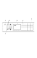
図1は本発明の実施形態に係るファクシミリ機能付きのプリンタ複合機の外観を示す斜視図である。筐体101の内部には、インクジェット方式のプリント部、スキャナ部、ファクシミリ部等が設けられている。装置上面には原稿読取装置(ADF)90と操作パネル70が設けられた圧板部が、ヒンジにより開閉自在に設けられている。圧板部を開けると原稿読取面が露出する。スキャナ部で原稿を読み取るには、原稿読取装置90で原稿を移動させながら読み取る方法と、圧板部を開けて原稿読取面の上に原稿を置いて読み取る方法の2通りが可能である。
FIG. 1 is a perspective view showing an appearance of a multifunction printer with a facsimile function according to an embodiment of the present invention. Inside the
操作パネル70には、横4×縦4のアレイ状に配列された計16個のボタンスイッチからなるアレイスイッチ部10が設けられている。本明細書では、横方向を第1方向、縦方向を第2方向とする。また、第1方向および第2方向に直交した、ボタンが押し下げられる方向を第3方向とする。操作パネル70には、さらにモードスイッチ20、電源スイッチ30、液晶ディスプレイ等の表示部50が設けられている。
The
図2は操作パネル70を上方から見た図である。操作者が電源スイッチ30を押すと装置が起動する。モードスイッチ20はCOPY(コピー)、FAX(ファクシミリ送受信)、SCAN(原稿読み取り)、CARD(メモリカード読み取り)の4つのモードのうちいずれかを選択するためのスイッチである。操作者がモードスイッチ20は4つのボタンのいずれかを押すと1つのモードが設定される。4つのボタン各々の近傍にインジケータ40が設けられ、押されたボタンに対応するインジケータ40が点灯する。モードスイッチ20によって設定されたモードは表示部50に表示される。さらに、モードスイッチ20で設定されたモードに応じて、アレイスイッチ部10の表示形態が変化する。
FIG. 2 is a view of the
図3はアレイスイッチ部10が表示し得るすべてのマークを表した図である。各ボタンには文字や記号等の2種類のマークが左右に並べて形成されており、設定されたモードに応じていずれか一方のマークが点灯、または両方が消灯する。この動作を実現するため、アレイスイッチ部10の各ボタンは、左側の表示部1(第1表示部)と右側の表示部2(第2表示部)を有する押圧部と、第1表示部を背面から照明する第1光源、および第2表示部を背面から照明する第2光源を有する。スイッチ構造の詳細については後述する。
FIG. 3 is a diagram showing all marks that can be displayed by the
図4はモードに応じてアレイスイッチ部10の表示が切り替わる様子を示した図である。
FIG. 4 is a diagram showing how the display of the
図4(a)は電源オフの状態におけるボタン表示である。電源オフではすべてのボタンの入力が無効であるのに対応して、ボタン表示をすべて消灯する。これにより操作者はボタン入力が無効であることを認識することができる。図4(b)はCOPYモード、SCANモードまたはCARDモードが設定されたときのボタン表示である。各ボタンにおいて、2つの表示部のうち左側の表示部1のバックライト光源を点灯して左側のマークを表示し、且つ右側の表示部のバックライト光源は消灯して右側のマークが表示されないようにする。なお、COPYモード、SCANモード、CARDモードのすべてを同じ表示状態にせずに、モードに応じて不要なボタンについては消灯するようにしてもよい。図4(c)はFAXモードが設定されたときのボタン表示である。各ボタンにおいて、2つの表示部のうち右側の表示部2のバックライト光源を点灯して右側のマークを表示し、且つ左側の表示部のバックライト光源は消灯して左側のマークが表示されないようにする。これにより操作者は設定されたモードに応じた各ボタンの機能を認識することができる。
FIG. 4A is a button display when the power is off. When the power is turned off, all button displays are turned off in response to invalid input of all buttons. Thereby, the operator can recognize that the button input is invalid. FIG. 4B is a button display when the COPY mode, the SCAN mode, or the CARD mode is set. In each button, the backlight light source of the
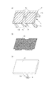
次に、アレイスイッチ部10の各ボタンのスイッチ構造の詳細について説明する。図5は各ボタンの構成部材の一つである押圧部を構成する3つのパーツを示す分解図である。図6は押圧部を構成するパーツの組み立て手順を説明するための図である。
Next, the details of the switch structure of each button of the
押圧部は、図5に示すように、キーフレーム11(図5(a))、フィルム13(図5(b))、キートップ12(図5(c))の3つのパーツからなる。 As shown in FIG. 5, the pressing portion is composed of three parts: a key frame 11 (FIG. 5A), a film 13 (FIG. 5B), and a key top 12 (FIG. 5C).
図5(a)、図6(c)を参照して、キーフレーム11は、背面から矢印Lの方向に照射されるバックライト光源からの光を透過拡散させる導光部11aが枠体に埋め込まれて、拡散層を提供する。キーフレーム11の裏面の中央には、左側の表示部と右側の表示部を分断するように、板体11wが裏面に対して鉛直に設けられている。板体11wの先端中央には後述するプッシュスイッチと当接する突起状の当接部11xを備えている。また、キーフレーム11の裏面の四隅には、板体11wと平行に伸びた4つの脚11bが設けられている。脚11bはそれぞれ、脚の自由端(先端)に後述する弾性部と当接する当接部11e、ならびにホルダにラッチされる爪11fが形成されている。さらに、キーフレーム11の裏面には、板体11wの両脇には2本の脚11c、および板体11wと直交する面を持った4つの側壁11dが、それぞれ裏面に対して鉛直に設けられている。脚11cの自由端(先端)の近傍には突起11tが形成されている。導光部11aを除いて、キーフレーム11の構成部材はすべて光を遮断する遮光性の黒色の樹脂部材からなる。導光部11aを除くキーフレーム11、板体11w、脚11b、脚11c、側壁11dは一体樹脂成型により作成される。導光部11aは樹脂成型されたキーフレーム11の開口に取り付けられる。なお、導光部11aは光を透過拡散する機能を有するものであればよく、透明樹脂の表面に梨地処理を施して作成したものであってもよい。
Referring to FIGS. 5A and 6C, in the
図5(b)を参照して、フィルム13は薄板状の透明基材の片面に印刷により遮光領域が形成され、表示するマークパターンが形成されたマーク層を提供する。マークパターンの形成には、透明基材に対してマーク部分にはインクを付与せずにそれ以外の領域にインクを付与するシルク印刷が好適である。図5(b)の例では、左側に「OK」の文字、右側に「5」の文字が透過領域として形成されている。これは、透過領域以外にインクが付与されるように透明基材の裏面側に抜き印刷を施すことにより作成される。なお、フィルム13を用いずに、キーフレーム11の導光部11aに直接印刷を施してマークを形成するようにしてもよい。
With reference to FIG.5 (b), the
図5(c)を参照して、キートップ12は、環境光を表面で反射する乳白色またはグレー色の光透過率の小さいスモーククリア樹脂からなる半透過性材料であり、半透過層を提供する。キートップ12の光透過率は例えば10%である。なお、キートップ12はクリア樹脂の表面がハーフミラー加工された半透過性材であってもよい。キートップ12の裏面には2つの脚12aが設けられ、脚12aの自由端(先端)の近傍には孔12tが形成されている。操作者はキートップ12の表面を指で押圧して押し下げることでスイッチ入力する。
Referring to FIG. 5C, the key top 12 is a translucent material made of a smoke clear resin having a low light transmittance of milky white or gray color that reflects ambient light on the surface, and provides a transflective layer. . The light transmittance of the key top 12 is, for example, 10%. The key top 12 may be a translucent material in which the surface of the clear resin is half mirror processed. Two
これら3のパーツの組み立て手順について図6を用いて説明する。最初に図6(a)のように、キーフレーム11に対してフィルム13を位置合わせして張り合わせる。次いで図6(b)、図6(c)のように、フィルム13が張り付けられたキーフレーム11の上からキートップ12を被せて、キーフレーム11に設けられた2本の脚の突起11tとキートップ12に設けられた2本の脚の孔12tとをそれぞれ係合させてラッチする。このラッチ機構により、使用中にキートップ12が容易に外れることが無いようにしている。図6(c)は、図6(b)を裏面側から見た様子を示す。
The procedure for assembling these three parts will be described with reference to FIG. First, as shown in FIG. 6A, the
このような構成において、バックライト光源からの光は拡散層で拡散され、フィルム13の光透過領域を通過し半透過層のキートップ12を通過して操作者に視認される。消灯している表示部はキートップ12の光透過率が小さいので操作者はほぼ視認できない。外光がキートップ12の側から照射されると、光はキートップ12を通過してフィルム13で反射して再びキートップ12を通過して外に戻る。光透過率が小さいキートップ12を往復で二度通過することで光は大きく減衰する。例えばキートップ12が光透過率10%であれば、二度の通過で光量は100分の1に減衰する。そのため、通常考えられる環境下の外光では操作者にはマークはほぼ視認できないようになっている。
In such a configuration, light from the backlight light source is diffused by the diffusion layer, passes through the light transmission region of the
フィルム13は、印刷が施された面を下にしてキーフレーム11の導光部11aに対向させる。これにより光源からの光はフィルムの透明基材の内部に進入する前に印刷面の遮光領域で遮光されるので、マーク表示のコントラストが向上して操作者の視認性が良好になる。仮に、フィルム13の印刷が施された面を上にしてキートップ12に対向させると、光源から光がフィルムの透明基材の内部に進入してその後に表面に印刷された遮光領域で遮光される。このとき、遮光領域で光が乱反射して反射光が再び透明基材を通過することにより、フィルム13の外周の縁を光らせてしまう現象が起きる。これは操作者にとってマークの視認性が低下することを意味する。
The
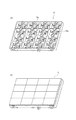
図7は、アレイスイッチ部10を構成するホルダの構造を示す斜視図であり、図7(a)はホルダの内部構造を示す。ホルダ15は、隣との間が遮光性の壁で仕切られた4×4の複数の矩形形状のセルがアレイ状に配列された構造を備える。各セルの内部には、細い樹脂バネからなる弾性部15aが設けられている。弾性部15aはホルダ15と同じ樹脂材料で樹脂一体成型で作成されたものである。なお、樹脂一体成型により作成した樹脂バネに限らず、ホルダ15とは別部品として弾性体からなる弾性部15aを設けるようにしてもよい。また、各セルの内部には、中央を横切るように規制部15gが設けられている。規制部15gは、その両側をセルの第2方向において対向する2つの内壁で固定され、且つ板体11wを両側から挟む2つの規制面を有している。
FIG. 7 is a perspective view showing the structure of the holder constituting the
複数のセルそれぞれの空間に、上述した構成の押圧部が第3方向(上下方向)に所定ストロークで移動可能となるよう挿入される。図7(b)はホルダが有する複数のセルにそれぞれ押圧部が挿入されアレイスイッチ部10の状態を示す。
The pressing portion having the above-described configuration is inserted into the space of each of the plurality of cells so as to be movable in a third direction (vertical direction) with a predetermined stroke. FIG. 7B shows a state of the
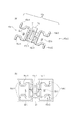
図8はセルの内部において弾性部15aおよび規制部15gの構造を、光源およびプッシュスイッチ21との関係で説明するための図であり、図8(a)は斜視図、図8(b)は上面図である。
FIG. 8 is a view for explaining the structure of the
規制部15gは中央に開口が設けられ、ここにキーフレーム11の板体11wが挿入される。開口の中心はプッシュスイッチ21の頭部の真上に位置する。第1方向においてキーフレーム11を移動または傾きを生じさせる力が働くと、規制部15の開口の内壁が板体11wと接触して、板体11wの移動と傾きを規制する。第2方向において規制部15gの両端は、セルの第2方向における対向する内壁にそれぞれ強固に固定される。本例では樹脂一体成型で作成することでホルダ15と規制部15gが一体化されている。この規制部15gは、キーフレーム11の傾きを抑制する機能、隣の空間への光の漏れを防ぐ機能、ならびにセルの強度ひいてはホルダ15全体の強度を補強する機能を兼ね備えたものである。
The restricting
弾性部15aは、第1光源22−1および第2光源22−2からの光を遮らないようにセルの内部に設けられている。弾性部15aは、第1弾性部15a−1と第2弾性部15a−2を含む。第1弾性部15a−1は、固定端15c−1が規制部15gの側面に取り付けられ且つ第1光源22−1の周りの一部を囲むように設けられている。第2弾性部15a−2は、固定端が規制部15gの別の側面に取り付けられ且つ第2光源22−2の周りの一部を囲むように設けられている。つまり、図8に示すように、第1弾性部15a−1、第2弾性部15a−2はそれぞれ、Ω(オーム)形状に類似した曲線形状を有し、その中央が固定端15c−1、15c−2によって規制部15gに固定されている。この曲線形状は、上方からみたとき、第1弾性部15a−1は第1光源22−1の周りの一部を囲み、第2弾性部15a−2は第2光源22−2の周りの一部を囲み、それぞれ光源から放射される光を遮らないような形状である。例えば、第1弾性部15a−1、第2弾性部15a−2はそれぞれ、0.5mm〜3.0mm程度の第3方向における厚みを有するプラスティックである。
The
第1弾性部15a−1は固定端15c−1から分岐して伸びた2つの自由端15d−1を有し、それぞれの自由端15d−1は押圧部の4つの脚11bのうち第1表示部の側に設けられた2つの脚11bのそれぞれの端部11eと当接する。第2弾性部15a−2は固定端15c−2から分岐して伸びた2つの自由端15d−2を有し、それぞれの自由端15d−2は4つの脚11bのうち第2表示部の側に設けられた2つの脚11bのそれぞれの端部11eと当接する。第1弾性部15a−1、第2弾性部15a−2はそれぞれ、細長く形成された樹脂バネ全体が弾性変形することにより、自由端15d−1、自由端15d−2が主に第3方向に所定範囲の移動ストロークを動くことができるようになっている。つまり、第1弾性部15a−1および第2弾性部15a−2は、第3方向において所定の移動ストロークの範囲で、ひび割れや折れが生じることなく全体が柔軟に変位してバネとして機能する。
The first
ホルダ15は操作パネル70の枠に固定され、ホルダ15の下には信号処理のための回路基板が設けられる。図9(a)は操作パネル70のパネルフレーム17の構成を示す。パネルフレーム17にはホルダ15が組み込まれて固定される。パネルフレーム17に対してホルダ15を別部品とすることで、フィルム13の交換などにおいて、ホルダ15を外して作業することができるので、作業性が向上する。なお、パネルフレーム17とホルダ15を同一部品とするようにしてもよい。
The
図9(b)は回路基板100の構成を示す。回路基板100の上には、ホルダ15の複数のセルに対応した位置に、プッシュスイッチ21とその両脇に第1光源22−1と第2光源22−2がはんだ付けで取り付けられている。プッシュスイッチ21は上方からの押圧によってオンになるメカニカルスイッチである。この例ではプッシュスイッチ21として薄型の金属ドームスイッチを用いている。光源22−1、第2光源22−2はLEDのような小型の半導体光源が好ましい。回路基板100の上には、さらに電源スイッチ30に対応するメカニカルスイッチ31、モードスイッチ20に対応する4つのメカニカルスイッチ41が取り付けられている。この例ではメカニカルスイッチ31、41として、タクトスイッチを用いている。
FIG. 9B shows the configuration of the
図10は、アレイスイッチ部10が組み立てられた状態を示す図であり、図10(a)は横から見た断面図、図10(b)は1つのセルにおける押圧部とホルダとの結合状態を示す斜視図である。
10A and 10B are diagrams showing a state in which the
キーフレームの板体11wは規制部15gの開口に挿入されて、板体11wの先端に設けられた当接部11xが下方に露出して、プッシュスイッチ21の真上に位置する。また、キーフレーム11の4つの脚11bの先端と弾性部15aの4つの自由端がそれぞれ当接する。すなわち、第1弾性部15a−1の2つの自由端15d−1は押圧部の4つの脚11bのうち第1表示部の側に設けられた2つの脚11bのそれぞれの端部11eと当接する。第2弾性部15a−2の2つの自由端15d−2は4つの脚11bのうち第2表示部の側に設けられた2つの脚11bのそれぞれの端部11eと当接する。
The
ここで、操作者が押圧部を指で矢印Pの方向に押圧すると、板体11wの当接部11xでプッシュスイッチ21の頭部が押されて、スイッチがオンになる。この際、第1弾性部15a−1、第2弾性部15a−2がそれぞれ弾性変形して、自由端15d−1、自由端15d−2が第3方向の下方に変位するので、弾性部に弾性力が押圧部を矢印Qの方向に押し戻す復元力として作用する。押圧部の四隅に均等に復元力が作用するので押圧部が傾きなく押し返されて、スイッチのスムーズな押圧操作感が得られる。弾性部15aは弱い押圧量でもスイッチ入力でき、且つ押し戻すのに必要な復元力は確保できる弾性力を持たせる形状とする。第1弾性部15a−1および第2弾性部15a−2は、固定端から長い距離をもって延びた先端に自由端が設けられているので、自由端が押圧されると全体が緩やかに撓んでスムーズな押圧操作感が得られる。
Here, when the operator presses the pressing portion with the finger in the direction of the arrow P, the head of the
キーフレーム11の脚11bの先端には外側に向けられた爪11fが形成されており、キーフレーム11をセルに挿入するとホルダ15に形成された係合部15bに爪11fがラッチされる。このラッチ機構によりいったん組み込んだ後はキーフレーム11が矢印Q方向に容易に抜けてしまうことは無い。弾性部15aはキーフレーム11の爪11fがラッチされた後も、キーフレーム11を矢印Q方向に付勢する。アレイスイッチ部10を構成する16個のスイッチのすべてについて、係止部15bを同じ高さに形成することでキートップ12の上面が均一な面に揃う。
A
上述したとおり、規制部15gは、セルの内部において板体11wを両側から非接触に挟む2つの規制面を有している。また、押圧部のキーフレーム11は4つの側壁11dを有している。キーフレーム11セルに対して、板体11wと規制部15gによりの第1方向(横方向)の移動および傾きが規制され、側壁11dとセルの第2方向(縦方向)において対向する内壁により第2方向の移動および傾きが規制される。このため、操作者がキートップの中央からずれた場所を押したとしても、キーフレーム11が第1方向および第2方向に大きく傾くことが防止され、確実なスイッチの入力が実現する。第1表示部と第2表示部は第1方向に長い長方形の形状を有しているので、操作者はキートップの表示された側の場所を押しがちである。つまり、第2方向よりも第1方向において傾きを生じさせる力が生じやすい。このような力が生じたとしても、板体11wと規制部15gが効果的に傾きを抑止して、信頼性の高いスイッチ装置が実現する。
As described above, the restricting
押し下げの抵抗が大きくならないように、板体11wの表面と規制部15gの規制面との間には隙間が設けられている。そのため、操作者がキートップの中央を押さない場合には、スイッチ入力が不安定になるほどの大きな傾きはないものの僅かな傾きを生じる。このようにキートップおよび板体11wが傾いたとしても、四隅の脚11bが弾性部の自由端15dから傾きを解消する方向にバネの反発力を受けるので、押圧操作感が損なわれない。
A gap is provided between the surface of the
また、弾性部15aは光源からの光を遮らないように光源の周りを囲むよう設けられているので、光源からの光が無駄なく表示部の照明に用いられ、照度の高いマーク表示がなされる。加えて、光透過性の低いにキートップ12を設けることで、部屋の照明や自然光が入射しても消灯している表示部のマークが視認しにくくなる。
Further, since the
また、セルの内部において、押圧部に設けられた板体11wは、第1光源22−1と第1表示部の間の第1空間と、第2光源22−2と第2表示部の間の第2空間を仕切るように位置する。また、規制部15gも第1空間と第2空間の間に位置する。これら板体11wと規制部15gをともに遮光性の部材としたことで、セルの内部において第1光源22−1からの光が第2表示部に漏れ入ること、および第2光源22−2からの光が第1表示部に漏れ入ることを抑止している。これにより、一方の表示部を点灯して他方を消灯した場合に、消灯した側の表示部が薄っすらと光ってしまうことが抑止されるので、操作者はボタンの機能を確実に認識することができる。また、ホルダ15のセルを区画する壁を遮光性の部材としたので、隣り合うセル同士での光の漏れも抑止される。
Further, inside the cell, the
アレイ状に配列されたキートップ12の隣との境界には微小な隙間が存在する。この隙間からのバックライト光源からの光が漏れてしまうと、必要のないところまで光ってしまう。これを防ぐ工夫について説明する。図10(a)において、第1光源22−1および第2光源22−2から放射される光はそれぞれ、ホルダ15の上部枠の稜線で決まる範囲(線L1と線L2で挟まれる範囲)で導光部11aに入射し、それよりも外側の光はホルダ15の内壁面で蹴られる。導光部11aに入射した光のうち、線L1を通過した光は透過拡散性の導光部11aを抜けて、キートップ12の下面と遮光壁15bの上面との間の空間に入光する。なお、線L2を通る光は板体11wの壁面によって遮られるので、隣の表示部には入射しない。この空間は、キートップ12を所定ストロークで押し下げることを可能とするために設けられているものである。この空間の上には前述したキートップ12の隙間が存在するので、このままでは空間に入った光が隙間から外に漏れる可能性がある。空間において遮光壁15bの上方且つキートップ12の下に位置するキーフレーム11のフレーム端11zが、この光漏れを防止する。すなわち、線L1の延長線の上に遮光部材としてフレーム端11zが位置し、導光部11aを抜けて空間に入った光をフレーム端11zが遮ることで、隙間から光が外に漏れることを防止している。こうして、隣り合うセルの間からの光の漏れが、遮光壁15bの上方に位置するキーフレーム11の部位によって確実に抑止され、漏れ光が操作者に視認されることがない。
There is a minute gap at the boundary between the key tops 12 arranged in an array. If light from the backlight light source from this gap leaks, it will shine to an unnecessary place. A device for preventing this will be described. In FIG. 10A, the light emitted from the first light source 22-1 and the second light source 22-2 is within a range determined by the ridge line of the upper frame of the holder 15 (a range between the line L1 and the line L2). Light incident on the
また、フレーム端11zはキートップ12が押し下げられたときに、遮光壁15bの上面と当接してそれ以上押し下げることができないような、所定の移動ストロークを規定するための規制部材でもある。つまり、フレーム端11zはストロークの移動規制と遮光の2つの機能を兼ね備えた部位として設けられたものである。
The frame end 11z is also a restricting member for defining a predetermined movement stroke so that when the key top 12 is pressed down, the frame end 11z is in contact with the upper surface of the
10 アレイスイッチ部
11 キーフレーム
11b 脚
11c 脚
11d 側壁
11e 当接部
11f 爪
11w 板体
11x 当接部
11z フレーム端
12 キートップ
13 フィルム
15 ホルダ
15a 弾性体
15a−1 第1弾性体
15a−2 第2弾性体
15g 規制部
21 プッシュスイッチ
22−1 第1光源
22−2 第2光源
DESCRIPTION OF
Claims (12)
前記押圧部に対応したセルを有するホルダと、
プッシュスイッチと、
前記第1表示部を背面から照明する第1光源、および前記第2表示部を背面から照明する第2光源と、
前記セルの内部において、前記第1光源と前記第1表示部の間の空間と、前記第2光源と前記第2表示部の間の空間を仕切るように前記押圧部に設けられた板体と、
前記セルの内部において前記板体を挟むように設けられた規制部を有し、
操作者が前記押圧部を押圧すると前記板体の一部で前記プッシュスイッチが押されることを特徴とするスイッチ装置。 A pressing portion having a first display portion and a second display portion;
A holder having a cell corresponding to the pressing portion;
A push switch,
A first light source that illuminates the first display unit from the back, and a second light source that illuminates the second display unit from the back;
A plate provided in the pressing portion so as to partition a space between the first light source and the first display unit and a space between the second light source and the second display unit inside the cell; ,
A regulating portion provided so as to sandwich the plate body inside the cell;
When the operator presses the pressing part, the push switch is pressed by a part of the plate.
前記第1光源および前記第2光源からの光を遮らないように前記セルの内部に弾性部が設けられており、前記弾性部は前記4つの脚のそれぞれの端部と当接する当接部を有し、
操作者が前記押圧部を押圧した際には、前記4つの脚のそれぞれに対して、前記弾性部から前記押圧部を押し戻す方向に復元力が作用することを特徴とする、請求項1に記載のスイッチ装置。 Four legs extending in parallel with the plate body are provided at the four corners of the pressing portion,
An elastic portion is provided inside the cell so as not to block light from the first light source and the second light source, and the elastic portion has a contact portion that contacts each end of the four legs. Have
The restoring force acts in a direction in which the pressing portion is pushed back from the elastic portion to each of the four legs when the operator presses the pressing portion. Switch device.
前記第1弾性部は前記固定端から分岐して伸びた2つの自由端を有し、それぞれの前記自由端は前記4つの脚のうち前記第1表示部の側に設けられた2つの脚のそれぞれの端部と当接し、
前記第2弾性部は前記固定端から分岐して伸びた2つの自由端を有し、それぞれの前記自由端は前記4つの脚のうち前記第2表示部の側に設けられた2つの脚のそれぞれの端部と当接する
ことを特徴とする、請求項2に記載のスイッチ装置。 The elastic portion includes a first elastic portion having a fixed end attached to the restricting portion and surrounding a part around the first light source, a fixed end attached to the restricting portion, and the second A second elastic portion provided so as to surround a part around the light source,
The first elastic portion has two free ends extending from the fixed end, and each of the free ends is formed by two legs provided on the first display portion side of the four legs. Abut each end,
The second elastic portion has two free ends extending from the fixed end, and each of the free ends is formed of two legs provided on the second display portion side of the four legs. The switch device according to claim 2, wherein the switch device is in contact with each end portion.
前記第1光源または前記第2光源からの光は、前記拡散層で拡散され前記マーク層の前記光透過領域を通過し前記キートップを通過して操作者に視認されることを特徴とする、請求項1から6のいずれか1項に記載のスイッチ装置。 Each of the first display unit and the second display unit includes a diffusion layer that transmits and diffuses light, a mark layer that is provided on the diffusion layer and has a mark pattern formed by a light transmission region and a light shielding region, Having a translucent key top provided on the mark layer,
The light from the first light source or the second light source is diffused by the diffusion layer, passes through the light transmission region of the mark layer, passes through the key top, and is visually recognized by an operator. The switch apparatus of any one of Claim 1 to 6.
Priority Applications (7)
| Application Number | Priority Date | Filing Date | Title |
|---|---|---|---|
| JP2010286529A JP5241812B2 (en) | 2010-12-22 | 2010-12-22 | Switch device |
| BRPI1106160-0A BRPI1106160A2 (en) | 2010-12-22 | 2011-11-28 | switching device and electronic device |
| DE102011119896.6A DE102011119896B4 (en) | 2010-12-22 | 2011-11-29 | switch device |
| KR1020110131035A KR101403202B1 (en) | 2010-12-22 | 2011-12-08 | Switch device and electronic apparatus |
| MYPI2011006065A MY158048A (en) | 2010-12-22 | 2011-12-14 | Switch device |
| CN201110425344.3A CN102543524B (en) | 2010-12-22 | 2011-12-15 | Switch device |
| US13/327,367 US8847089B2 (en) | 2010-12-22 | 2011-12-15 | Switch device |
Applications Claiming Priority (1)
| Application Number | Priority Date | Filing Date | Title |
|---|---|---|---|
| JP2010286529A JP5241812B2 (en) | 2010-12-22 | 2010-12-22 | Switch device |
Publications (2)
| Publication Number | Publication Date |
|---|---|
| JP2012134064A true JP2012134064A (en) | 2012-07-12 |
| JP5241812B2 JP5241812B2 (en) | 2013-07-17 |
Family
ID=46315352
Family Applications (1)
| Application Number | Title | Priority Date | Filing Date |
|---|---|---|---|
| JP2010286529A Active JP5241812B2 (en) | 2010-12-22 | 2010-12-22 | Switch device |
Country Status (7)
| Country | Link |
|---|---|
| US (1) | US8847089B2 (en) |
| JP (1) | JP5241812B2 (en) |
| KR (1) | KR101403202B1 (en) |
| CN (1) | CN102543524B (en) |
| BR (1) | BRPI1106160A2 (en) |
| DE (1) | DE102011119896B4 (en) |
| MY (1) | MY158048A (en) |
Cited By (29)
| Publication number | Priority date | Publication date | Assignee | Title |
|---|---|---|---|---|
| JP2015069644A (en) * | 2013-09-30 | 2015-04-13 | アップル インコーポレイテッド | Keycaps having reduced thickness |
| JP2016225280A (en) * | 2015-06-02 | 2016-12-28 | キヤノン株式会社 | Input device having push-type key and image forming apparatus |
| US9704665B2 (en) | 2014-05-19 | 2017-07-11 | Apple Inc. | Backlit keyboard including reflective component |
| US9710069B2 (en) | 2012-10-30 | 2017-07-18 | Apple Inc. | Flexible printed circuit having flex tails upon which keyboard keycaps are coupled |
| US9715978B2 (en) | 2014-05-27 | 2017-07-25 | Apple Inc. | Low travel switch assembly |
| US9761389B2 (en) | 2012-10-30 | 2017-09-12 | Apple Inc. | Low-travel key mechanisms with butterfly hinges |
| US9779889B2 (en) | 2014-03-24 | 2017-10-03 | Apple Inc. | Scissor mechanism features for a keyboard |
| US9793066B1 (en) | 2014-01-31 | 2017-10-17 | Apple Inc. | Keyboard hinge mechanism |
| US9870880B2 (en) | 2014-09-30 | 2018-01-16 | Apple Inc. | Dome switch and switch housing for keyboard assembly |
| US9908310B2 (en) | 2013-07-10 | 2018-03-06 | Apple Inc. | Electronic device with a reduced friction surface |
| US9916945B2 (en) | 2012-10-30 | 2018-03-13 | Apple Inc. | Low-travel key mechanisms using butterfly hinges |
| US9927895B2 (en) | 2013-02-06 | 2018-03-27 | Apple Inc. | Input/output device with a dynamically adjustable appearance and function |
| US9934915B2 (en) | 2015-06-10 | 2018-04-03 | Apple Inc. | Reduced layer keyboard stack-up |
| US9971084B2 (en) | 2015-09-28 | 2018-05-15 | Apple Inc. | Illumination structure for uniform illumination of keys |
| US9997308B2 (en) | 2015-05-13 | 2018-06-12 | Apple Inc. | Low-travel key mechanism for an input device |
| US9997304B2 (en) | 2015-05-13 | 2018-06-12 | Apple Inc. | Uniform illumination of keys |
| US10002727B2 (en) | 2013-09-30 | 2018-06-19 | Apple Inc. | Keycaps with reduced thickness |
| US10083805B2 (en) | 2015-05-13 | 2018-09-25 | Apple Inc. | Keyboard for electronic device |
| US10082880B1 (en) | 2014-08-28 | 2018-09-25 | Apple Inc. | System level features of a keyboard |
| US10115544B2 (en) | 2016-08-08 | 2018-10-30 | Apple Inc. | Singulated keyboard assemblies and methods for assembling a keyboard |
| US10128064B2 (en) | 2015-05-13 | 2018-11-13 | Apple Inc. | Keyboard assemblies having reduced thicknesses and method of forming keyboard assemblies |
| US10262814B2 (en) | 2013-05-27 | 2019-04-16 | Apple Inc. | Low travel switch assembly |
| US10353485B1 (en) | 2016-07-27 | 2019-07-16 | Apple Inc. | Multifunction input device with an embedded capacitive sensing layer |
| WO2019215958A1 (en) * | 2018-05-11 | 2019-11-14 | 株式会社東海理化電機製作所 | Operation device |
| US10755877B1 (en) | 2016-08-29 | 2020-08-25 | Apple Inc. | Keyboard for an electronic device |
| US10775850B2 (en) | 2017-07-26 | 2020-09-15 | Apple Inc. | Computer with keyboard |
| US10796863B2 (en) | 2014-08-15 | 2020-10-06 | Apple Inc. | Fabric keyboard |
| JP2022119495A (en) * | 2021-02-04 | 2022-08-17 | 株式会社デンソーテン | switch |
| US11500538B2 (en) | 2016-09-13 | 2022-11-15 | Apple Inc. | Keyless keyboard with force sensing and haptic feedback |
Families Citing this family (9)
| Publication number | Priority date | Publication date | Assignee | Title |
|---|---|---|---|---|
| US9713274B2 (en) * | 2013-09-18 | 2017-07-18 | Sony Corporation | Electronic apparatus |
| USD737227S1 (en) | 2014-03-26 | 2015-08-25 | Gentex Corporation | Button assembly |
| JP1531092S (en) * | 2014-12-12 | 2015-08-17 | ||
| JP1531093S (en) * | 2014-12-12 | 2015-08-17 | ||
| JP6421694B2 (en) * | 2015-05-14 | 2018-11-14 | オムロン株式会社 | Switch unit and game machine |
| US9742939B2 (en) * | 2015-06-02 | 2017-08-22 | Canon Kabushiki Kaisha | Input device having push-keys, and image forming apparatus having the same |
| WO2019202688A1 (en) * | 2018-04-18 | 2019-10-24 | 三菱電機株式会社 | Switch |
| CN108917478A (en) * | 2018-06-02 | 2018-11-30 | 新乡市光明电器有限公司 | Military In-vehicle device controller and its control assembly |
| KR102456632B1 (en) * | 2020-12-28 | 2022-10-19 | 주식회사 스위치코리아 | Power switch indicator assembly and manufacturing method thereof |
Citations (9)
| Publication number | Priority date | Publication date | Assignee | Title |
|---|---|---|---|---|
| JPS56113376U (en) * | 1980-01-30 | 1981-09-01 | ||
| JPS6149935U (en) * | 1984-09-06 | 1986-04-03 | ||
| JPS61146824U (en) * | 1985-03-01 | 1986-09-10 | ||
| JPH0169287U (en) * | 1987-10-28 | 1989-05-08 | ||
| JPH0292618U (en) * | 1989-01-10 | 1990-07-23 | ||
| JP2001236847A (en) * | 2000-02-23 | 2001-08-31 | Shin Etsu Polymer Co Ltd | Material for push-button switch |
| JP2004134274A (en) * | 2002-10-11 | 2004-04-30 | Kojima Press Co Ltd | Push button switch |
| JP2006120491A (en) * | 2004-10-22 | 2006-05-11 | Toshiba Corp | Push-button device and electrical equipment |
| JP4080322B2 (en) * | 2002-12-24 | 2008-04-23 | アルプス電気株式会社 | Illumination mechanism of operation panel device |
Family Cites Families (8)
| Publication number | Priority date | Publication date | Assignee | Title |
|---|---|---|---|---|
| US4354077A (en) * | 1980-06-11 | 1982-10-12 | Jay-El Products Incorporated | Push-button panel assembly including an individually lighted push-button switch assembly |
| DE4039379C1 (en) * | 1990-12-10 | 1992-04-30 | Siemens Nixdorf Informationssysteme Ag, 4790 Paderborn, De | |
| JPH0650191A (en) | 1992-03-23 | 1994-02-22 | Honda Motor Co Ltd | Intake air quantity controller during of deceleration of internal combustion engine |
| JPH0650191U (en) * | 1992-12-15 | 1994-07-08 | クラリオン株式会社 | Light source mounting device |
| DE4401644C2 (en) * | 1994-01-21 | 1997-02-06 | Kammerer Gmbh M | Push button for actuating control elements, in particular heating, air conditioning and ventilation regulators in motor vehicles |
| KR100339130B1 (en) * | 1999-09-07 | 2002-05-31 | 세곡우 | Key switch |
| JP2005242983A (en) * | 2004-01-30 | 2005-09-08 | Ntt Docomo Inc | Input key and input device |
| US8309870B2 (en) * | 2011-01-04 | 2012-11-13 | Cody George Peterson | Leveled touchsurface with planar translational responsiveness to vertical travel |
-
2010
- 2010-12-22 JP JP2010286529A patent/JP5241812B2/en active Active
-
2011
- 2011-11-28 BR BRPI1106160-0A patent/BRPI1106160A2/en not_active Application Discontinuation
- 2011-11-29 DE DE102011119896.6A patent/DE102011119896B4/en not_active Expired - Fee Related
- 2011-12-08 KR KR1020110131035A patent/KR101403202B1/en active IP Right Grant
- 2011-12-14 MY MYPI2011006065A patent/MY158048A/en unknown
- 2011-12-15 CN CN201110425344.3A patent/CN102543524B/en not_active Expired - Fee Related
- 2011-12-15 US US13/327,367 patent/US8847089B2/en not_active Expired - Fee Related
Patent Citations (9)
| Publication number | Priority date | Publication date | Assignee | Title |
|---|---|---|---|---|
| JPS56113376U (en) * | 1980-01-30 | 1981-09-01 | ||
| JPS6149935U (en) * | 1984-09-06 | 1986-04-03 | ||
| JPS61146824U (en) * | 1985-03-01 | 1986-09-10 | ||
| JPH0169287U (en) * | 1987-10-28 | 1989-05-08 | ||
| JPH0292618U (en) * | 1989-01-10 | 1990-07-23 | ||
| JP2001236847A (en) * | 2000-02-23 | 2001-08-31 | Shin Etsu Polymer Co Ltd | Material for push-button switch |
| JP2004134274A (en) * | 2002-10-11 | 2004-04-30 | Kojima Press Co Ltd | Push button switch |
| JP4080322B2 (en) * | 2002-12-24 | 2008-04-23 | アルプス電気株式会社 | Illumination mechanism of operation panel device |
| JP2006120491A (en) * | 2004-10-22 | 2006-05-11 | Toshiba Corp | Push-button device and electrical equipment |
Cited By (48)
| Publication number | Priority date | Publication date | Assignee | Title |
|---|---|---|---|---|
| US9916945B2 (en) | 2012-10-30 | 2018-03-13 | Apple Inc. | Low-travel key mechanisms using butterfly hinges |
| US11023081B2 (en) | 2012-10-30 | 2021-06-01 | Apple Inc. | Multi-functional keyboard assemblies |
| US10699856B2 (en) | 2012-10-30 | 2020-06-30 | Apple Inc. | Low-travel key mechanisms using butterfly hinges |
| US9710069B2 (en) | 2012-10-30 | 2017-07-18 | Apple Inc. | Flexible printed circuit having flex tails upon which keyboard keycaps are coupled |
| US10254851B2 (en) | 2012-10-30 | 2019-04-09 | Apple Inc. | Keyboard key employing a capacitive sensor and dome |
| US9761389B2 (en) | 2012-10-30 | 2017-09-12 | Apple Inc. | Low-travel key mechanisms with butterfly hinges |
| US10211008B2 (en) | 2012-10-30 | 2019-02-19 | Apple Inc. | Low-travel key mechanisms using butterfly hinges |
| US10114489B2 (en) | 2013-02-06 | 2018-10-30 | Apple Inc. | Input/output device with a dynamically adjustable appearance and function |
| US9927895B2 (en) | 2013-02-06 | 2018-03-27 | Apple Inc. | Input/output device with a dynamically adjustable appearance and function |
| US10262814B2 (en) | 2013-05-27 | 2019-04-16 | Apple Inc. | Low travel switch assembly |
| US10556408B2 (en) | 2013-07-10 | 2020-02-11 | Apple Inc. | Electronic device with a reduced friction surface |
| US9908310B2 (en) | 2013-07-10 | 2018-03-06 | Apple Inc. | Electronic device with a reduced friction surface |
| US11699558B2 (en) | 2013-09-30 | 2023-07-11 | Apple Inc. | Keycaps having reduced thickness |
| US10804051B2 (en) | 2013-09-30 | 2020-10-13 | Apple Inc. | Keycaps having reduced thickness |
| JP2015069644A (en) * | 2013-09-30 | 2015-04-13 | アップル インコーポレイテッド | Keycaps having reduced thickness |
| US10002727B2 (en) | 2013-09-30 | 2018-06-19 | Apple Inc. | Keycaps with reduced thickness |
| US9704670B2 (en) | 2013-09-30 | 2017-07-11 | Apple Inc. | Keycaps having reduced thickness |
| US10224157B2 (en) | 2013-09-30 | 2019-03-05 | Apple Inc. | Keycaps having reduced thickness |
| US9793066B1 (en) | 2014-01-31 | 2017-10-17 | Apple Inc. | Keyboard hinge mechanism |
| US9779889B2 (en) | 2014-03-24 | 2017-10-03 | Apple Inc. | Scissor mechanism features for a keyboard |
| US9704665B2 (en) | 2014-05-19 | 2017-07-11 | Apple Inc. | Backlit keyboard including reflective component |
| US9715978B2 (en) | 2014-05-27 | 2017-07-25 | Apple Inc. | Low travel switch assembly |
| US10796863B2 (en) | 2014-08-15 | 2020-10-06 | Apple Inc. | Fabric keyboard |
| US10082880B1 (en) | 2014-08-28 | 2018-09-25 | Apple Inc. | System level features of a keyboard |
| US9870880B2 (en) | 2014-09-30 | 2018-01-16 | Apple Inc. | Dome switch and switch housing for keyboard assembly |
| US10134539B2 (en) | 2014-09-30 | 2018-11-20 | Apple Inc. | Venting system and shield for keyboard |
| US10192696B2 (en) | 2014-09-30 | 2019-01-29 | Apple Inc. | Light-emitting assembly for keyboard |
| US10128061B2 (en) | 2014-09-30 | 2018-11-13 | Apple Inc. | Key and switch housing for keyboard assembly |
| US9997304B2 (en) | 2015-05-13 | 2018-06-12 | Apple Inc. | Uniform illumination of keys |
| US9997308B2 (en) | 2015-05-13 | 2018-06-12 | Apple Inc. | Low-travel key mechanism for an input device |
| US10083805B2 (en) | 2015-05-13 | 2018-09-25 | Apple Inc. | Keyboard for electronic device |
| US10083806B2 (en) | 2015-05-13 | 2018-09-25 | Apple Inc. | Keyboard for electronic device |
| US10128064B2 (en) | 2015-05-13 | 2018-11-13 | Apple Inc. | Keyboard assemblies having reduced thicknesses and method of forming keyboard assemblies |
| US10424446B2 (en) | 2015-05-13 | 2019-09-24 | Apple Inc. | Keyboard assemblies having reduced thickness and method of forming keyboard assemblies |
| US10468211B2 (en) | 2015-05-13 | 2019-11-05 | Apple Inc. | Illuminated low-travel key mechanism for a keyboard |
| JP2016225280A (en) * | 2015-06-02 | 2016-12-28 | キヤノン株式会社 | Input device having push-type key and image forming apparatus |
| US9934915B2 (en) | 2015-06-10 | 2018-04-03 | Apple Inc. | Reduced layer keyboard stack-up |
| US10310167B2 (en) | 2015-09-28 | 2019-06-04 | Apple Inc. | Illumination structure for uniform illumination of keys |
| US9971084B2 (en) | 2015-09-28 | 2018-05-15 | Apple Inc. | Illumination structure for uniform illumination of keys |
| US10353485B1 (en) | 2016-07-27 | 2019-07-16 | Apple Inc. | Multifunction input device with an embedded capacitive sensing layer |
| US10115544B2 (en) | 2016-08-08 | 2018-10-30 | Apple Inc. | Singulated keyboard assemblies and methods for assembling a keyboard |
| US11282659B2 (en) | 2016-08-08 | 2022-03-22 | Apple Inc. | Singulated keyboard assemblies and methods for assembling a keyboard |
| US10755877B1 (en) | 2016-08-29 | 2020-08-25 | Apple Inc. | Keyboard for an electronic device |
| US11500538B2 (en) | 2016-09-13 | 2022-11-15 | Apple Inc. | Keyless keyboard with force sensing and haptic feedback |
| US10775850B2 (en) | 2017-07-26 | 2020-09-15 | Apple Inc. | Computer with keyboard |
| WO2019215958A1 (en) * | 2018-05-11 | 2019-11-14 | 株式会社東海理化電機製作所 | Operation device |
| JP2022119495A (en) * | 2021-02-04 | 2022-08-17 | 株式会社デンソーテン | switch |
| JP7266051B2 (en) | 2021-02-04 | 2023-04-27 | 株式会社デンソーテン | switch |
Also Published As
| Publication number | Publication date |
|---|---|
| CN102543524B (en) | 2014-10-15 |
| KR20120071323A (en) | 2012-07-02 |
| MY158048A (en) | 2016-08-30 |
| DE102011119896A1 (en) | 2012-06-28 |
| US20120160643A1 (en) | 2012-06-28 |
| DE102011119896B4 (en) | 2017-05-04 |
| JP5241812B2 (en) | 2013-07-17 |
| BRPI1106160A2 (en) | 2013-04-09 |
| CN102543524A (en) | 2012-07-04 |
| KR101403202B1 (en) | 2014-06-02 |
| US8847089B2 (en) | 2014-09-30 |
Similar Documents
| Publication | Publication Date | Title |
|---|---|---|
| JP5241812B2 (en) | Switch device | |
| US7186935B2 (en) | Keypad assembly for a portable terminal | |
| EP1724800B1 (en) | Key pad and keypad assembly | |
| JP5045755B2 (en) | LIGHTING STRUCTURE FOR KEY OPERATION UNIT, ELECTRONIC DEVICE, PORTABLE DEVICE, AND LIGHTING METHOD FOR KEY OPERATION UNIT | |
| TWI409842B (en) | Sheet switch module | |
| US7959342B2 (en) | Waveguide member and keypad assembly using the same | |
| JP2009099386A (en) | Key switch structure | |
| TWM541103U (en) | Luminous keyboard | |
| WO2010024137A1 (en) | Input device | |
| JP5272032B2 (en) | Keyboard device | |
| JP3185841B2 (en) | Illuminated panel switch | |
| JPH08263207A (en) | Input/output device for portable terminal | |
| US20220139645A1 (en) | Input device and image forming apparatus including the same | |
| JP2016167426A (en) | Push button switch | |
| JP5535736B2 (en) | Keyboard with light source for lighting | |
| JP4708488B2 (en) | Keyboard device | |
| JP2001251401A (en) | Portable terminal | |
| JP4433643B2 (en) | Portable terminal device and portable electronic device | |
| JP4172479B2 (en) | Illuminated part structure and portable electronic device using the same | |
| CN113661553A (en) | Key switch and lighting switch device | |
| JPH08227634A (en) | Key switch structure for electronic equipment | |
| JP2009087560A (en) | Electronic equipment | |
| JP2010129324A (en) | Portable electronic device | |
| JP2002250919A (en) | Illuminator, liquid crystal display device, and apparatus incorporating the same | |
| JP2014060662A (en) | Portable terminal device |
Legal Events
| Date | Code | Title | Description |
|---|---|---|---|
| A977 | Report on retrieval |
Free format text: JAPANESE INTERMEDIATE CODE: A971007 Effective date: 20121206 |
|
| A131 | Notification of reasons for refusal |
Free format text: JAPANESE INTERMEDIATE CODE: A131 Effective date: 20121218 |
|
| A521 | Written amendment |
Free format text: JAPANESE INTERMEDIATE CODE: A523 Effective date: 20130208 |
|
| TRDD | Decision of grant or rejection written | ||
| A01 | Written decision to grant a patent or to grant a registration (utility model) |
Free format text: JAPANESE INTERMEDIATE CODE: A01 Effective date: 20130305 |
|
| A61 | First payment of annual fees (during grant procedure) |
Free format text: JAPANESE INTERMEDIATE CODE: A61 Effective date: 20130402 |
|
| FPAY | Renewal fee payment (event date is renewal date of database) |
Free format text: PAYMENT UNTIL: 20160412 Year of fee payment: 3 |
|
| FPAY | Renewal fee payment (event date is renewal date of database) |
Free format text: PAYMENT UNTIL: 20160412 Year of fee payment: 3 |