JP2012132459A - Fan - Google Patents
Fan Download PDFInfo
- Publication number
- JP2012132459A JP2012132459A JP2011283411A JP2011283411A JP2012132459A JP 2012132459 A JP2012132459 A JP 2012132459A JP 2011283411 A JP2011283411 A JP 2011283411A JP 2011283411 A JP2011283411 A JP 2011283411A JP 2012132459 A JP2012132459 A JP 2012132459A
- Authority
- JP
- Japan
- Prior art keywords
- nozzle
- air
- air inlet
- axis
- wall
- Prior art date
- Legal status (The legal status is an assumption and is not a legal conclusion. Google has not performed a legal analysis and makes no representation as to the accuracy of the status listed.)
- Granted
Links
Images


Classifications
-
- F—MECHANICAL ENGINEERING; LIGHTING; HEATING; WEAPONS; BLASTING
- F24—HEATING; RANGES; VENTILATING
- F24F—AIR-CONDITIONING; AIR-HUMIDIFICATION; VENTILATION; USE OF AIR CURRENTS FOR SCREENING
- F24F7/00—Ventilation
- F24F7/007—Ventilation with forced flow
-
- F—MECHANICAL ENGINEERING; LIGHTING; HEATING; WEAPONS; BLASTING
- F04—POSITIVE - DISPLACEMENT MACHINES FOR LIQUIDS; PUMPS FOR LIQUIDS OR ELASTIC FLUIDS
- F04D—NON-POSITIVE-DISPLACEMENT PUMPS
- F04D25/00—Pumping installations or systems
- F04D25/02—Units comprising pumps and their driving means
- F04D25/08—Units comprising pumps and their driving means the working fluid being air, e.g. for ventilation
- F04D25/088—Ceiling fans
-
- F—MECHANICAL ENGINEERING; LIGHTING; HEATING; WEAPONS; BLASTING
- F04—POSITIVE - DISPLACEMENT MACHINES FOR LIQUIDS; PUMPS FOR LIQUIDS OR ELASTIC FLUIDS
- F04D—NON-POSITIVE-DISPLACEMENT PUMPS
- F04D29/00—Details, component parts, or accessories
- F04D29/40—Casings; Connections of working fluid
- F04D29/52—Casings; Connections of working fluid for axial pumps
- F04D29/54—Fluid-guiding means, e.g. diffusers
- F04D29/541—Specially adapted for elastic fluid pumps
- F04D29/545—Ducts
-
- F—MECHANICAL ENGINEERING; LIGHTING; HEATING; WEAPONS; BLASTING
- F04—POSITIVE - DISPLACEMENT MACHINES FOR LIQUIDS; PUMPS FOR LIQUIDS OR ELASTIC FLUIDS
- F04D—NON-POSITIVE-DISPLACEMENT PUMPS
- F04D29/00—Details, component parts, or accessories
- F04D29/60—Mounting; Assembling; Disassembling
- F04D29/64—Mounting; Assembling; Disassembling of axial pumps
- F04D29/644—Mounting; Assembling; Disassembling of axial pumps especially adapted for elastic fluid pumps
- F04D29/646—Mounting or removal of fans
-
- F—MECHANICAL ENGINEERING; LIGHTING; HEATING; WEAPONS; BLASTING
- F04—POSITIVE - DISPLACEMENT MACHINES FOR LIQUIDS; PUMPS FOR LIQUIDS OR ELASTIC FLUIDS
- F04F—PUMPING OF FLUID BY DIRECT CONTACT OF ANOTHER FLUID OR BY USING INERTIA OF FLUID TO BE PUMPED; SIPHONS
- F04F5/00—Jet pumps, i.e. devices in which flow is induced by pressure drop caused by velocity of another fluid flow
- F04F5/14—Jet pumps, i.e. devices in which flow is induced by pressure drop caused by velocity of another fluid flow the inducing fluid being elastic fluid
- F04F5/16—Jet pumps, i.e. devices in which flow is induced by pressure drop caused by velocity of another fluid flow the inducing fluid being elastic fluid displacing elastic fluids
- F04F5/20—Jet pumps, i.e. devices in which flow is induced by pressure drop caused by velocity of another fluid flow the inducing fluid being elastic fluid displacing elastic fluids for evacuating
-
- F—MECHANICAL ENGINEERING; LIGHTING; HEATING; WEAPONS; BLASTING
- F04—POSITIVE - DISPLACEMENT MACHINES FOR LIQUIDS; PUMPS FOR LIQUIDS OR ELASTIC FLUIDS
- F04F—PUMPING OF FLUID BY DIRECT CONTACT OF ANOTHER FLUID OR BY USING INERTIA OF FLUID TO BE PUMPED; SIPHONS
- F04F5/00—Jet pumps, i.e. devices in which flow is induced by pressure drop caused by velocity of another fluid flow
- F04F5/44—Component parts, details, or accessories not provided for in, or of interest apart from, groups F04F5/02 - F04F5/42
- F04F5/46—Arrangements of nozzles
-
- F—MECHANICAL ENGINEERING; LIGHTING; HEATING; WEAPONS; BLASTING
- F24—HEATING; RANGES; VENTILATING
- F24F—AIR-CONDITIONING; AIR-HUMIDIFICATION; VENTILATION; USE OF AIR CURRENTS FOR SCREENING
- F24F2221/00—Details or features not otherwise provided for
- F24F2221/14—Details or features not otherwise provided for mounted on the ceiling
-
- F—MECHANICAL ENGINEERING; LIGHTING; HEATING; WEAPONS; BLASTING
- F24—HEATING; RANGES; VENTILATING
- F24F—AIR-CONDITIONING; AIR-HUMIDIFICATION; VENTILATION; USE OF AIR CURRENTS FOR SCREENING
- F24F2221/00—Details or features not otherwise provided for
- F24F2221/16—Details or features not otherwise provided for mounted on the roof
Abstract
Description
本発明は、部屋内で空気流を生成するための送風機アセンブリに関する。好ましい実施形態では、送風機アセンブリは、天井送風機の形態である。 The present invention relates to a blower assembly for generating an air flow in a room. In a preferred embodiment, the blower assembly is in the form of a ceiling blower.
多くの天井送風機が公知である。標準的な天井送風機は、第1の軸線周りに取り付けられた1組の羽根と、その1組の羽根を回転させるために同じく第1の軸線周りに取り付けられた駆動装置とを含む。別のタイプの天井送風機は、部屋の中に下方へ空気の柱を生成する。例えば、英国特許第2,049,161号明細書は、天井から吊られたドーム状支持体と、支持体の内面に結合された電動インペラを有する天井送風機とを記載する。インペラから放出された空気流は、空気通路のアレイを含むほぼ円筒形の本体を通じて運ばれ、天井送風機から放出される線形空気流れを生成する。 Many ceiling fans are known. A standard ceiling blower includes a set of vanes mounted about a first axis and a drive device also mounted about the first axis to rotate the set of vanes. Another type of ceiling blower creates a column of air down into the room. For example, British Patent 2,049,161 describes a dome-like support suspended from a ceiling and a ceiling blower having an electric impeller coupled to the inner surface of the support. The air flow emitted from the impeller is carried through a generally cylindrical body that includes an array of air passages to produce a linear air flow that is emitted from the ceiling blower.
第1の態様では、本発明は、部屋内で空気流を生成するための送風機アセンブリを提供し、送風機アセンブリは、空気入口、インペラ、及び空気入口を通じて空気流を引き込むためにインペラ軸線の周りでインペラを回転させるためのモータを含む空気入口部分と、内壁、内壁の周りに延びる外壁、空気流を放出するための少なくとも1つの空気出口、及び少なくとも1つの空気出口に空気流を搬送するために内壁と外壁の間に位置付けられた内部通路を含み、内壁が、ノズルの外側からの空気が少なくとも1つの空気出口から放出された空気流によって引き込まれるボアを形成する環状ノズルと、部屋の天井で空気入口部分及びノズルを支持する支持アセンブリとを含む。 In a first aspect, the present invention provides a blower assembly for generating an air flow in a room, the blower assembly around an impeller axis to draw the air flow through the air inlet, the impeller, and the air inlet. An air inlet portion including a motor for rotating the impeller, an inner wall, an outer wall extending around the inner wall, at least one air outlet for discharging an air flow, and for conveying the air flow to the at least one air outlet; An annular nozzle including an internal passage positioned between the inner wall and the outer wall, the inner wall forming a bore through which air from outside the nozzle is drawn by an air flow emitted from at least one air outlet; and a ceiling of the room And an air inlet portion and a support assembly that supports the nozzle.
環状ノズルから放出された空気流は、ノズルを取り囲む空気を同伴し、これは、従って、放出された空気流及び同伴された空気をユーザに供給する空気増幅器として作用する。同伴された空気は、本明細書では2次空気流と称される。2次空気流は、ノズルを取り囲む部屋空間、領域、又は外部環境から引き込まれる。放出された空気流は、同伴された2次空気流と合体してノズルから前方に放出される合体した又は全体的な空気流を形成する。2次空気流の一部分は、ノズルのボアを通じて引き込まれ、一方、2次空気流の他の部分は、外壁の外側の周り及びノズルの前を通り、ボアの下流で放出された空気流と合体する。 The air flow emitted from the annular nozzle entrains the air surrounding the nozzle, which thus acts as an air amplifier that supplies the user with the emitted air flow and the entrained air. Entrained air is referred to herein as secondary air flow. The secondary air flow is drawn from the room space, area or external environment surrounding the nozzle. The discharged air stream merges with the entrained secondary air stream to form a combined or total air stream that is discharged forward from the nozzle. Part of the secondary air flow is drawn through the nozzle bore, while the other part of the secondary air flow passes around the outside of the outer wall and in front of the nozzle and merges with the air flow emitted downstream of the bore. To do.
内壁は、ボアの周りに延びかつそれを定めるために環状の形状であることが好ましい。内部通路は、内壁と外壁の間に配置されることが好ましく、少なくとも部分的に、内壁及び外壁によって定められることがより好ましい。ノズルは、空気流を受け入れる少なくとも1つの空気入口を含む。外壁は、空気入口を定めることが好ましい。例えば、その又は各空気入口は、外壁に形成された孔の形態とすることができる。ノズルは、内壁と外壁の間に延びる空気出口部分を含むことが好ましい。空気出口部分は、内壁と外壁の間に接続された別個の構成部品とすることができる。代替的に、空気出口部分の少なくとも一部は、内壁及び外壁のうちの一方と一体とすることができる。空気出口部分は、好ましくはノズルの端壁、より好ましくは下側端壁の少なくとも一部を形成する。空気出口部分は、好ましくは、少なくとも部分的に、空気流を放出するためのノズルの少なくとも1つの空気出口を定める。空気出口は、空気出口部分に形成することができる。代替的に、空気出口は、空気出口部分と内壁及び外壁のうちの一方との間に配置されてもよい。ノズルの空気入口は、ノズルの空気出口と実質的に直交することが好ましい。 The inner wall preferably has an annular shape extending around and defining the bore. The internal passage is preferably disposed between the inner wall and the outer wall, more preferably at least partially defined by the inner wall and the outer wall. The nozzle includes at least one air inlet that receives an air flow. The outer wall preferably defines an air inlet. For example, the or each air inlet can be in the form of a hole formed in the outer wall. The nozzle preferably includes an air outlet portion extending between the inner wall and the outer wall. The air outlet portion can be a separate component connected between the inner wall and the outer wall. Alternatively, at least a portion of the air outlet portion can be integral with one of the inner wall and the outer wall. The air outlet portion preferably forms at least a portion of the end wall of the nozzle, more preferably the lower end wall. The air outlet portion preferably defines, at least in part, at least one air outlet of the nozzle for emitting an air flow. The air outlet can be formed in the air outlet portion. Alternatively, the air outlet may be disposed between the air outlet portion and one of the inner wall and the outer wall. The air inlet of the nozzle is preferably substantially perpendicular to the air outlet of the nozzle.
空気出口部分は、ボア軸線から離れる方向に空気流を放出するように構成される、好ましくは外方にテーパ付きの円錐の形状であることが好ましい。ボア軸線から離れるように延びる方向へのノズルからの空気流の放出は、放出された空気流による2次空気流の同伴の程度を増大させ、従って、送風機アセンブリによって生成される合体空気流の流量を増大することができることを本発明者は見出した。ここでは、合体空気流の流量又は最大速度の絶対値又は相対値は、ノズルの空気出口の直径の3倍の距離で記録された値を参照している。 The air outlet portion is preferably in the shape of a conical taper, preferably outwardly configured to discharge airflow away from the bore axis. The discharge of the air flow from the nozzle in a direction extending away from the bore axis increases the degree of entrainment of the secondary air flow by the discharged air flow, and thus the combined air flow rate produced by the blower assembly. The inventor has found that can be increased. Here, the absolute value or relative value of the flow rate or maximum velocity of the combined air flow refers to a value recorded at a distance three times the diameter of the nozzle air outlet.
いかなる理論にも縛られることを望まないが、2次空気流の同伴の割合は、ノズルから放出される空気流の外側プロフィールの表面積の大きさに関連付けることができると考えられる。放出された空気流が外方にテーパ付きか又はフレア状態である時に、外側プロフィールの表面積は、比較的大きく、それによって放出される空気流及びノズルを取り囲む空気の混合が促進され、従って、合体空気流の流量が増大する。ノズルによって生成された合体空気流の流量を増大させることには、合体空気流の最大速度を低減する効果がある。これは、ノズルが、部屋又はオフィスを通る空気の流れを生成するための送風機アセンブリに使用されるのに適している。 Without wishing to be bound by any theory, it is believed that the rate of entrainment of the secondary air flow can be related to the size of the surface area of the outer profile of the air flow emitted from the nozzle. When the discharged air flow is outwardly tapered or flared, the surface area of the outer profile is relatively large, thereby facilitating mixing of the discharged air flow and the air surrounding the nozzle, and thus coalescing. The air flow rate increases. Increasing the flow rate of the combined air flow generated by the nozzle has the effect of reducing the maximum velocity of the combined air flow. This is suitable for the nozzle to be used in a blower assembly for generating a flow of air through a room or office.
空気出口部分は、内壁に接続された内側部分及び外壁に接続された外側部分を含むことが好ましい。少なくとも1つの空気出口は、環状壁の内側部分と外側部分の間に位置付けることができる。内側部分の少なくとも一部は、ボア軸線から離れる方向にテーパ付けられていてもよい。ボア軸線に対する内側部分のこの部分の傾斜角は、0°と45°の間とすることができる。内側部分のこの部分は、実質的に円錐である形状を有することが好ましい。空気出口部分は、内側部分のこの部分と実質的に平行である方向に空気流を放出するように構成することができる。外側部分は、ボア軸線と実質的に直交することが好ましい。 The air outlet portion preferably includes an inner portion connected to the inner wall and an outer portion connected to the outer wall. At least one air outlet may be located between the inner and outer portions of the annular wall. At least a portion of the inner portion may be tapered in a direction away from the bore axis. The inclination angle of this part of the inner part with respect to the bore axis can be between 0 ° and 45 °. This part of the inner part preferably has a shape that is substantially conical. The air outlet portion may be configured to emit an air flow in a direction that is substantially parallel to this portion of the inner portion. The outer portion is preferably substantially perpendicular to the bore axis.
少なくとも1つの空気出口は、ボア軸線周りに延びることが好ましい。ノズルは、ボア軸線周りに角度的に離間させて設けられた複数の空気出口を含むことができるが、好ましい実施形態では、ノズルは、実質的に環状の空気出口を含む。 The at least one air outlet preferably extends around the bore axis. Although the nozzle can include a plurality of air outlets that are angularly spaced about the bore axis, in a preferred embodiment, the nozzle includes a substantially annular air outlet.
少なくとも1つの空気出口は、ボア軸線から離れるように延びる方向に空気を放出するように成形することができる。空気出口に隣接して位置付けられた内部通路の一部分は、放出された空気流がボア軸線から離れる方向に差し向けられるように、空気出口を通る空気流を向けるように形状付けられることができる。製造を容易にするために、空気出口部分は、空気出口を通して空気流を差し向けるための空気チャンネルを含むことができる。空気チャンネルは、ボア軸線に対して傾斜していることが好ましく、ほぼ切頭円錐形の形状を有することが好ましい。空気チャンネルとボア軸線の間に内在する角度は、0°と45°の間であることが好ましい。好ましい実施形態では、この角度は、約15°である。内部通路は、ボア軸線周りに延びることが好ましく、ボア軸線を取り囲むことが好ましい。内部通路は、ボア軸線を通過する平面内で任意の望ましい断面を有することができる。好ましい実施形態では、内部通路は、ボア軸線を通過する平面内で実質的に矩形断面を有する。 The at least one air outlet may be shaped to release air in a direction extending away from the bore axis. A portion of the internal passage located adjacent to the air outlet can be shaped to direct the air flow through the air outlet such that the emitted air flow is directed away from the bore axis. To facilitate manufacturing, the air outlet portion can include an air channel for directing air flow through the air outlet. The air channel is preferably inclined with respect to the bore axis and preferably has a substantially frustoconical shape. The angle inherent between the air channel and the bore axis is preferably between 0 ° and 45 °. In a preferred embodiment, this angle is about 15 °. The internal passage preferably extends around the bore axis and preferably surrounds the bore axis. The internal passage can have any desired cross section in a plane passing through the bore axis. In a preferred embodiment, the internal passage has a substantially rectangular cross section in a plane passing through the bore axis.
ノズルは、ノズルの内壁と外壁の中間に延びる翼弦線を含むことができる。少なくとも1つの空気出口は、ボア軸線と翼弦線の間に位置付けられることが好ましい。 The nozzle can include a chord line extending midway between the inner and outer walls of the nozzle. The at least one air outlet is preferably located between the bore axis and the chord line.
支持アセンブリは、部屋の天井に取付可能である取付ブラケットを含むことが好ましい。この取付ブラケットは、例えば、ネジを使用して天井に取付可能である板の形態とすることができる。支持アセンブリは、好ましくはインペラ軸線が取付ブラケットに対して90°未満の角度であるように、より好ましくはインペラ軸線が取付ブラケットに対して45°未満の角度であるように空気入口部分及びノズルを支持するように構成されることが好ましい。一実施形態では、支持アセンブリは、インペラ軸線が取付ブラケットと実質的に平行であるように空気入口部分及びノズルを支持するように構成される。ボア軸線は、インペラ軸線と実質的に直交することが好ましく、従って、支持アセンブリは、ボア軸線が取付ブラケットと実質的に直交するように空気入口部分及びノズルを支持するように構成することができる。空気入口部分及びノズルは、ボア軸線に沿って測定した時に実質的に同じ深さを有することが好ましい。 The support assembly preferably includes a mounting bracket that is attachable to the ceiling of the room. The mounting bracket can be in the form of a plate that can be mounted to the ceiling using screws, for example. The support assembly preferably includes the air inlet portion and the nozzle so that the impeller axis is at an angle of less than 90 ° to the mounting bracket, and more preferably the impeller axis is at an angle of less than 45 ° to the mounting bracket. It is preferably configured to support. In one embodiment, the support assembly is configured to support the air inlet portion and the nozzle such that the impeller axis is substantially parallel to the mounting bracket. The bore axis is preferably substantially perpendicular to the impeller axis, and thus the support assembly can be configured to support the air inlet portion and the nozzle such that the bore axis is substantially perpendicular to the mounting bracket. . Preferably, the air inlet portion and the nozzle have substantially the same depth when measured along the bore axis.
これにより、取付ブラケットが取り付けられる水平天井と送風機アセンブリが実質的に平行に位置するように送風機を配置することができる。ノズルは、比較的天井の近くに位置付けることができ、ユーザ又はユーザが所持する品目がノズルと接触する危険が低減される。 Accordingly, the blower can be arranged such that the horizontal ceiling to which the mounting bracket is attached and the blower assembly are located substantially in parallel. The nozzle can be positioned relatively close to the ceiling, reducing the risk that a user or an item he / she carries will come into contact with the nozzle.
空気入口部分の入口は、1次空気流が空気入口部分の中に引き込まれる単一の孔又は複数の孔を含むことができる。空気入口は、好ましくは、インペラ軸線が空気入口を通過するように、より好ましくはインペラ軸線が空気入口部分の空気入口と実質的に直交するように配置される。 The inlet of the air inlet portion can include a single hole or multiple holes through which the primary air flow is drawn into the air inlet portion. The air inlet is preferably arranged such that the impeller axis passes through the air inlet, more preferably the impeller axis is substantially perpendicular to the air inlet of the air inlet portion.
空気入口部分のサイズを最小にするために、インペラは、軸流インペラであることが好ましい。空気入口部分は、ノズルに向けて空気流を案内するためにインペラから下流に位置付けられたディフューザを含むことが好ましい。空気入口部分は、外側ケーシングと、モータ及びインペラ周りに延びるシュラウドと、外側ケーシング内にシュラウドを取り付けるための取付構造とを好ましくは含む。ディフューザは、モータを支持するための内側環状壁と、シュラウドに接続された外側環状壁と、内壁及び外壁の間に位置付けられた複数の湾曲ベーンとを含むことが好ましい。ケーシング及びシュラウドは、実質的に円筒形であることが好ましい。 In order to minimize the size of the air inlet portion, the impeller is preferably an axial impeller. The air inlet portion preferably includes a diffuser positioned downstream from the impeller to guide the air flow toward the nozzle. The air inlet portion preferably includes an outer casing, a shroud extending around the motor and impeller, and a mounting structure for mounting the shroud within the outer casing. The diffuser preferably includes an inner annular wall for supporting the motor, an outer annular wall connected to the shroud, and a plurality of curved vanes positioned between the inner and outer walls. The casing and shroud are preferably substantially cylindrical.
取付構造は、外側ケーシングとシュラウドの間に位置付けられた複数のマウントと、マウントとシュラウドの間に接続された複数の弾性要素とを含むことができる。好ましくはシュラウドが外側ケーシングと実質的に同軸であるように外側ケーシングに対してシュラウドを位置決めすることに加えて、弾性要素は、送風機アセンブリの使用中に生成された振動を吸収することができる。弾性要素は、マウントとシュラウドの間で緊張状態に保持されることが好ましく、かつ各々が一端でシュラウドにかつ別の端部で支持体の1つに接続された複数の引張バネを含むことが好ましい。バネを緊張状態に維持するために、引張バネの端部を付勢して離すための手段を設けることができる。例えば、取付構成は、マウントを付勢して離すように付勢するためにマウント間に位置付けられたスペーサリングを含み、これにより、各バネの一端を他端から離すことができる。 The mounting structure can include a plurality of mounts positioned between the outer casing and the shroud and a plurality of elastic elements connected between the mount and the shroud. In addition to positioning the shroud with respect to the outer casing, preferably so that the shroud is substantially coaxial with the outer casing, the elastic element is capable of absorbing vibrations generated during use of the blower assembly. The elastic element is preferably held in tension between the mount and the shroud and includes a plurality of tension springs each connected to the shroud at one end and one of the supports at the other end. preferable. Means can be provided for biasing and releasing the end of the tension spring to maintain the spring in tension. For example, the mounting arrangement can include a spacer ring positioned between the mounts to bias the mounts away, thereby allowing one end of each spring to be separated from the other end.
第2の態様では、本発明は、ケーシング内にモータを支持するための装置を提供し、装置は、モータに接続されてその周りに延びるシュラウドと、ケーシングとシュラウドの間に位置付けられた複数のマウントと、マウントとシュラウドの間に接続された複数の弾性要素とを含み、弾性要素は、マウントとシュラウドの間で緊張状態に保持される。 In a second aspect, the present invention provides an apparatus for supporting a motor in a casing, the apparatus comprising a shroud connected to and extending about the motor, and a plurality of positioned between the casing and the shroud. The mount includes a plurality of elastic elements connected between the mount and the shroud, the elastic elements being held in tension between the mount and the shroud.
空気入口部分は、好ましくは、支持アセンブリとノズルの間に位置付けることができる。空気入口部分の一端は、支持アセンブリに接続され、空気入口部分の他端は、ノズルに接続されることが好ましい。空気入口部分は、実質的に円筒形であることが好ましい。 The air inlet portion can preferably be positioned between the support assembly and the nozzle. One end of the air inlet portion is preferably connected to the support assembly and the other end of the air inlet portion is connected to the nozzle. The air inlet portion is preferably substantially cylindrical.
支持アセンブリは、空気出口の上流に配置された空気通路を含むことができる。インペラによって生成された空気流は、空気通路を通過する。支持アセンブリ及び空気入口部分の相対位置に応じて、空気通路は、空気入口部分へ又はそこから空気を搬送することができる。例えば、支持アセンブリの空気通路は、インペラとモータとを収容する空気入口部分の空気通路と実質的に同軸とすることができる。 The support assembly can include an air passage disposed upstream of the air outlet. The air flow generated by the impeller passes through the air passage. Depending on the relative position of the support assembly and the air inlet portion, the air passage may carry air to or from the air inlet portion. For example, the air passage of the support assembly can be substantially coaxial with the air passage of the air inlet portion that houses the impeller and the motor.
ノズルは、1次空気流が部屋の中に放出される方向をユーザが変更することを可能にするために支持アセンブリに対して回転可能であることが好ましい。ノズルは、回転軸周りに、かつ空気流が天井から離れる方向に差し向けられる第1の向きと空気流が天井の方向に差し向けられる第2の向きとの間で支持アセンブリに対して回転可能であることが好ましい。例えば、夏期には、ユーザは、送風機アセンブリによって生成される空気流によって送風機アセンブリの下に位置するユーザを涼しくするための比較的涼しい微風が得られるように、空気流が、送風機アセンブリが取り付けられた天井から離れる方向に部屋の中に放出されるようにノズルの向きを変えたいと思う場合がある。しかし、冬期には、ユーザは、送風機アセンブリのすぐ下で微風を生成することなく、部屋の壁の上側部分に上がった温かい空気を移動かつ循環させるために空気流が天井の方向に放出されるように180°にわたってノズルを反転させたいと思う場合がある。 The nozzle is preferably rotatable relative to the support assembly to allow the user to change the direction in which the primary air flow is discharged into the room. The nozzle is rotatable relative to the support assembly about a rotational axis and between a first orientation in which the air flow is directed away from the ceiling and a second orientation in which the air flow is directed toward the ceiling. It is preferable that For example, in the summer, the air flow is attached to the blower assembly so that the air flow generated by the blower assembly provides a relatively cool breeze to cool the user located under the blower assembly. You may want to change the orientation of the nozzles so that they are released into the room away from the ceiling. However, in winter, the user releases airflow in the direction of the ceiling to move and circulate the warm air that has risen to the upper part of the room wall without generating a breeze just below the blower assembly. You may want to reverse the nozzle over 180 degrees.
ノズルは、それが第1の向きと第2の向きの間で回転する時に反転させることができる。ノズルの回転軸は、実質的にボア軸線と直交することが好ましく、かつインペラ軸線と実質的に同一平面上であることが好ましい。 The nozzle can be reversed when it rotates between a first orientation and a second orientation. The rotation axis of the nozzle is preferably substantially orthogonal to the bore axis and is preferably substantially coplanar with the impeller axis.
ノズルは、空気入口部分及び支持アセンブリの両方に対して回転可能にすることができる。代替的に、空気入口部分は、空気入口部分及びノズルの両方が支持アセンブリに対して回転可能であるように支持アセンブリに接続することができる。 The nozzle can be rotatable relative to both the air inlet portion and the support assembly. Alternatively, the air inlet portion can be connected to the support assembly such that both the air inlet portion and the nozzle are rotatable relative to the support assembly.
支持アセンブリは、天井に送風機アセンブリを取り付けるための天井マウントと、天井マウントに接続された第1の端部を有するアームと、アームの第2の端部とノズル及び空気入口部分のうちの一方とに接続された本体とを含むことが好ましい。本体は、ノズルまたは空気入口部分に直結することができる。本体は、環状本体であることが好ましく、これは、空気出口まで空気流を搬送するための空気通路を含む。 The support assembly includes a ceiling mount for attaching the blower assembly to the ceiling, an arm having a first end connected to the ceiling mount, a second end of the arm and one of the nozzle and the air inlet portion. And a main body connected to the main body. The body can be directly connected to the nozzle or air inlet portion. The body is preferably an annular body, which includes an air passage for carrying an air flow to the air outlet.
本体は、上昇位置と下降位置の間でノズルを移動させるためにアームに対してピボット回転可能であることが好ましい。ノズル及び空気入口部分は、従って、支持アセンブリの取付ブラケットに対してピボット回転可能にすることができる。ノズルを下降させることは、ノズルと送風機アセンブリが取り付けられた天井との間の距離を増大させ、従って、ノズルを天井と接触することなく支持アセンブリに対して回転させることができる。ノズルを下降させることは、ユーザによるその回転を容易にすることができる。 The body is preferably pivotable relative to the arm for moving the nozzle between the raised and lowered positions. The nozzle and air inlet portion can thus be pivotable relative to the mounting bracket of the support assembly. Lowering the nozzle increases the distance between the nozzle and the ceiling to which the blower assembly is attached, so that the nozzle can be rotated relative to the support assembly without contacting the ceiling. Lowering the nozzle can facilitate its rotation by the user.
ノズル及び空気入口部分は、インペラ軸線と実質的に直交するピボット軸の周りにピボット回転可能であることが好ましい。本体は、従って、インペラ軸線と実質的に直交するピボット軸周りにアームに対してピボット回転可能であることが好ましい。ピボット軸は、ノズルのボア軸線と実質的に直交することが好ましい。インペラ軸線は、ノズルが上昇位置にあって支持アセンブリが実質的に水平天井に接続される時に、実質的に水平であることが好ましい。 The nozzle and air inlet portion are preferably pivotable about a pivot axis substantially perpendicular to the impeller axis. The body is therefore preferably pivotable relative to the arm about a pivot axis substantially perpendicular to the impeller axis. The pivot axis is preferably substantially orthogonal to the nozzle bore axis. The impeller axis is preferably substantially horizontal when the nozzle is in the raised position and the support assembly is connected to a substantially horizontal ceiling.
本体は、上昇位置から下降位置までノズルを移動させるために5°から45°の範囲の角度でピボット回転可能にすることができる。ノズルの外壁の半径に応じて、本体は、上昇位置から下降位置までノズルを移動させるために10°から20°の範囲の角度でピボット回転することができる。本体は、ノズルがその上昇位置に維持されるようにアームに対して本体をロックするための解除可能なロック機構を収容することが好ましい。ロック機構は、ノズルをその下降位置に移動させることでユーザによって解除可能である。ロック機構は、ノズルがその上昇位置に維持されるようにアームに対して本体をロックするためのロック構造に向かって付勢されることが好ましい。ロック機構は、ノズルが下降位置から上昇位置に移動する時にロック構造に自動的に戻るように構成されることが好ましい。 The body can be pivotable at an angle in the range of 5 ° to 45 ° to move the nozzle from the raised position to the lowered position. Depending on the radius of the outer wall of the nozzle, the body can pivot at an angle in the range of 10 ° to 20 ° to move the nozzle from the raised position to the lowered position. The body preferably houses a releasable locking mechanism for locking the body relative to the arm so that the nozzle is maintained in its raised position. The lock mechanism can be released by the user by moving the nozzle to its lowered position. The locking mechanism is preferably biased toward a locking structure for locking the body relative to the arm so that the nozzle is maintained in its raised position. The locking mechanism is preferably configured to automatically return to the locking structure when the nozzle moves from the lowered position to the raised position.
アームは、天井マウントに回転可能に接続されることが好ましい。アームは、回転軸周りに天井マウントに対して回転可能であることが好ましく、アームは、回転軸に対して傾斜することが好ましい。その結果、アームがその回転軸周りに回転すると、ノズル及び空気入口は、回転軸周りを周回する。それによってノズルを比較的広い環状区域内の望ましい位置に移動させることができる。アームは、ノズルと天井の間の距離を最小にするために、回転軸に対して45°から75°まで範囲の角度で傾斜することが好ましい。アームの回転軸は、本体のピボット軸と実質的に直交することが好ましい。 The arm is preferably rotatably connected to the ceiling mount. The arm is preferably rotatable relative to the ceiling mount about a rotation axis, and the arm is preferably inclined with respect to the rotation axis. As a result, when the arm rotates about its rotation axis, the nozzle and the air inlet go around the rotation axis. Thereby, the nozzle can be moved to a desired position within a relatively large annular area. The arm is preferably inclined at an angle ranging from 45 ° to 75 ° with respect to the axis of rotation in order to minimize the distance between the nozzle and the ceiling. The rotation axis of the arm is preferably substantially orthogonal to the pivot axis of the main body.
本発明の第1の態様に関連して上述した特徴は、本発明の第2の態様に等しく適用可能であり、その逆も同様である。 Features described above in connection with the first aspect of the invention are equally applicable to the second aspect of the invention, and vice versa.
ここで、本発明の好ましい特徴を単に一例として図面を参照して以下に説明する。 The preferred features of the present invention will now be described by way of example only with reference to the drawings.
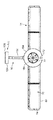
図1〜図5は、部屋内で空気流を生成する送風機アセンブリを示している。この例において、送風機アセンブリは、部屋の天井Cに接続可能である天井送風機10の形態である。天井送風機10は、空気流を生成する空気入口部分12、空気流を放出する環状ノズル14、及び部屋の天井Cに空気入口部分12及びノズル14を支持する支持アセンブリ16を含む。
1-5 show a blower assembly that generates an air flow in a room. In this example, the blower assembly is in the form of a
空気入口部分12は、ノズル14から放出される1次空気流を生成するシステムを収容するほぼ円筒形の外側ケーシング18を含む。図1、図2、及び図5に示すように、外側ケーシング18には、外側ケーシング18の長手方向軸線L周りに離間している複数の軸線方向に延びる補強リブ20を形成することができるが、これらのリブ20は、外側ケーシング18が形成される材料の強度によっては省略することができる。
The
図6及び図7をここで参照すると、空気入口部分12は、天井送風機10に1次空気流を引き込むインペラ22を収容する。インペラ22は、外側ケーシング18の長手方向軸線Lと実質的に同一直線上であるインペラ軸線周りに回転可能である軸流インペラの形態である。インペラ22は、モータ26から外方に延びる回転シャフト24に接続される。この実施形態では、モータ26は、支持アセンブリ16内に位置付けられる制御回路(図示せず)により可変である速度を有するDCブラシレスモータである。モータ26は、前側モータケーシング部分28及び後側モータケーシング部分30を含むモータケーシング内に収容される。組み立て中、モータ26は、最初に前側モータケーシング部分28に挿入され、次に、後側モータケーシング部分30が、モータケーシング内でモータ26を前後モータケーシング部分両方で保持して支えるように前側ケーシング部分28に挿入される。
With reference now to FIGS. 6 and 7, the
空気入口部分12は、インペラ22の下流に位置付けられるディフューザも収容する。ディフューザは、ディフューザの内側円筒壁34と外側円筒外壁の間に位置付けられる複数のディフューザベーン32を含む。ディフューザは、単一部品として成形されることが好ましいが、代替的に、ディフューザは、互いに接続された複数の部品又は部分で形成することができる。内側円筒壁34は、モータケーシング周りに延びてモータケーシングを支持する。外側円筒壁は、インペラ22及びモータケーシング周りに延びるシュラウド36を提供する。この例において、シュラウド36は、実質的に円筒形である。シュラウド36は、その一端に設けられ1次空気流が天井送風機10の空気入口部分12に入る空気入口38と、他端に設けられ1次空気流が天井送風機10の空気入口部分12から排出される空気出口40とを含む。インペラ22及びシュラウド36は、インペラ22及びモータケーシングがディフューザによって支持される時に、インペラ22のベーン先端がシュラウド36の内面の直近にあるが接触せず、かつインペラ22がシュラウド36と実質的に同軸であるように形状付けられる。円筒形案内部材42が、インペラ22の回転によって生成された1次空気流をシュラウド36の空気出口40の方向に案内するために、ディフューザの内側円筒壁34の後側に接続される。
The
空気入口部分12は、インペラ軸線が外側ケーシング18の長手方向軸線Lと実質的に同一直線上であるように外側ケーシング18内にディフューザを取り付ける取付構造を含む。取付構造は、外側ケーシング18とシュラウド36の間に延びる環状チャネル44に位置付けられる。取付構造は、第1のマウント46と第1のマウント46から長手方向軸線Lに沿って軸線方向に離間している第2のマウント48とを含む。第1のマウント46は、長手方向軸線Lに沿って相互に軸線方向に離間している1対の相互に結合された弓形部材46a、46bを含む。第2のマウント48は、同様に、長手方向軸線Lに沿って相互に軸線方向に離間している1対の相互に結合された弓形部材48a、48bを含む。各マウント46、48の弓形部材46a、48aは、複数のバネコネクタ50を含み、それらの各々は、それぞれの引張バネ(図示せず)の一端に接続される。この例において、取付構造は、4つの引張バネを含み、これらの弓形部材46a、48aの各々は、2つの直径方向に反対側のコネクタ50を含む。各引張バネの他端は、シュラウド36内に形成されたそれぞれのバネコネクタ52に接続される。マウント46、48は、引張バネがコネクタ50、52の間で緊張状態に保持されるように、マウント46、48の間で環状チャネル44に挿入された弓形スペーサリング54により離れる方向に付勢される。これは、マウント46、48に対するシュラウド36の或る程度の半径方向の移動がモータケーシングから外側ケーシング18への振動の伝達を低減することを可能にしながら、シュラウド36とマウント46、48の間に規則正しい間隔を維持する役目をする。可撓性シール56が、1次空気流の一部が環状チャネル44に沿ってシュラウド36の空気入口40に戻るのを防止するために環状チャネル44の一端に設けられる。
The
環状の取付ブラケット58は、例えば、ボルト60により、シュラウド36の空気出口42周りに延びる外側ケーシング18の端部に接続される。天井送風機10のノズル14の環状のフランジ62が、例えば、ボルト64により取付ブラケット58に接続される。代替的に、取付ブラケット58は、ノズル14と一体とすることができる。
The
図1〜図5に戻ると、ノズル14は、外側部分70と、ノズルの上端で(図示のように)外側部分70に接続された内側部分72とを含む。外側部分70は、ノズル14の外側側壁74を定めるように互いに接続された複数の弓形部分を含む。内側部分72は、ノズル14の環状の内側側壁76を定めるように各々が外側部分70のそれぞれの部分に接続された複数の弓形部分を同様に含む。外壁74は、内壁76の周りに延びる。内壁76は、ノズルのボア78を定めるように中心ボア軸線Xの周りに延びる。ボア軸線Xは、外側ケーシング18の長手方向軸線Lと実質的に直交する。ボア78は、ボア軸線Xに沿って直径が変わるほぼ円形断面を有する。ノズルも、外壁74の一端と内壁76の一端との間に延びる環状上壁80と、外壁74の他端と内壁76の他端との間に延びる環状下壁82とを含む。内側部分70は、上壁80に沿って実質的に中間に外側部分72に接続され、一方、ノズルの外側部分72は、下壁82の大部分を形成する。
Returning to FIGS. 1-5, the
図8を特に参照すると、ノズル14は、環状空気出口部分84も含む。出口部分84は、内壁76の下端に接続された内側のほぼ切頭円錐の内側部分86を含む。内側部分86は、ボア軸線から離れる方向にテーパ付けられている。この実施形態では、内側部分86とボア軸線Xの間に内在する角度は、約15°である。出口部分84は、ノズル14の外側部分70の下端に接続され、かつノズルの環状下壁82の一部を定める環状外側部分88も含む。出口部分84の内側部分86及び外側部分88は、ボア軸線Xの周りの内側部分86と外側部分88の間の間隔を制御する役目をする複数のウェブ(図示せず)により互いに接続される。出口部分84は、単一部品として構成することができるが、互いに接続された複数の構成要素として構成することもできる。代替的に、内側部分86は、内側部分70と一体とすることができ、外側部分88は、外側部分72と一体とすることができる。この場合、内側部分86及び外側部分88の一方には、ボア軸線Xの周りの内側部分86と外側部分88の間の間隔を制御するために、内側部分86及び外側部分88の他方の部分と係合する複数のスペーサを形成することができる。
With particular reference to FIG. 8, the
内壁76は、翼形の表面の一部の形状であるボア軸線Xを含む平面における断面プロフィールを有すると考えることができる。この翼形は、ノズルの上壁80に位置する前縁と、ノズルの下壁82に位置する後縁と、前縁と後縁の間に延びる翼弦線CLとを有する。この実施形態では、翼弦線CLは、ボア軸線Xとほぼ平行である。
The
ノズル14の空気出口90は、出口部分84の内側部分86と外側部分88の間に位置付けられる。空気出口90は、図6に示すように、ノズル14の内壁76の近くに、及び従って翼弦線CL及びボア軸線Xの間に、ノズル14の下壁82に位置付けられると考えることができる。空気出口90は、環状スロットの形態であることが好ましい。空気出口90は、形状がほぼ円形であり、ボア軸線Xに垂直である平面内に位置付けられることが好ましい。空気出口90は、0.5から5mmの範囲で比較的一定の幅を有することが好ましい。
The
空気入口部分12にノズル14を接続する環状フランジ62は、ノズルの外側部分70の各部分のうちの1つと一体である。フランジ62は、空気入口部分12から1次空気流を受け入れるために、ノズルの空気入口92の周りに延びると考えることができる。ノズル14の外側部分70のこの部分は、ノズル14の環状の内部通路94に1次空気流を搬送するように形状付けられる。ノズル14の外壁74、内壁76、上壁80、及び下壁82は、一緒になって、ボア軸線Xの周りに延びる内部通路94を定める。内部通路94は、ボア軸線Xを通過する平面においてほぼ矩形の断面を有する。
An
図8に示すように、空気出口部分84は、空気出口90を通じて1次空気流を差し向ける空気チャンネル96を含む。空気チャンネル96の幅は、空気出口90の幅と実質的に同じである。この実施形態では、空気チャンネル96は、空気チャンネル96が翼形の翼弦線CL及びノズル14のボア軸線Xに対して傾斜するように、ボア軸線Xから離れるように延びる方向Dに、空気出口90に向かって延びている。
As shown in FIG. 8, the air outlet portion 84 includes an
方向Dへのボア軸線X又は翼弦線CLの傾斜角は、任意の値を取ることができる。角度は、0°から45°の範囲であることが好ましい。この実施形態では、傾斜角は、ボア軸線Xの周りに実質的に一定であり、約15°である。ボア軸線Xへの空気チャンネル96の傾きは、従って、ボア軸線Xへの内側部分86の傾きと実質的に同じである。
The inclination angle of the bore axis X or the chord line CL in the direction D can take an arbitrary value. The angle is preferably in the range of 0 ° to 45 °. In this embodiment, the tilt angle is substantially constant about the bore axis X and is about 15 °. The inclination of the
1次空気流は、従って、ノズル14のボア軸線Xに大して傾斜している方向Dに、ノズル14から放出される。1次空気流は、ノズル14の内壁76から離れる方向にも放出される。空気チャンネル96がボア軸線Xから離れる方向に延びるように空気チャンネル96の形状を制御することにより、天井送風機10によって発生する合体空気流の流量は、1次空気流が、実質的にボア軸線Xと平行であるか又はボア軸線Xの方向に傾斜している方向Dに放出される時に発生する合体空気流の流量と比較して、増大させることができる。いかなる理論にも縛られることを望まないが、これは、比較的大きい表面積を有する外側プロフィールを有する1次空気流の放出によるものであると考えられる。この例において、1次空気流は、一般的に外方にテーパ付けられている円錐の形状のノズル14から放出される。この表面積の増大により、ノズル14を取り囲む空気との1次空気流の混合が促進され、1次空気流による2次空気流の同伴が増大し、従って、合体空気流の流量が増大する。
The primary air flow is thus discharged from the
図1〜図5に再び戻ると、支持アセンブリ16は、天井Cに天井送風機10を取り付ける天井マウント100と、天井マウント100に接続された第1の端部及び支持アセンブリ100の本体104に接続された第2の端部を有するアーム102とを含む。本体104は、天井送風機10の空気入口部分12に接続される。
Returning again to FIGS. 1-5, the
天井マウント100は、取付ブラケット106を含み、取付ブラケット108は、孔108に挿通可能なネジを使用して部屋の天井Cに接続可能である。図9及び図10を参照すると、天井マウント100は、取付ブラケット106にアーム102の第1の端部110を結合する結合アセンブリを更に含む。結合アセンブリは、結合円板112を含み、結合円板112は、結合円板112が回転軸R周りに取付ブラケット106に対して回転可能であるように取付ブラケット106の環状チャンネル116内に受け入れられる環状リム114を有する。アーム102は、好ましくは45°から75°までの範囲であり、この例においては約60°である角度θだけ回転軸Rに対して傾斜している。その結果、アーム102が回転軸Rの周りに回転すると、空気入口部分102及びノズルは、回転軸Rの周りの軌動を有する。
The
アーム102の第1の端部110は、結合アセンブリの多数の結合部材118、120、122により結合円盤112に接続される。結合アセンブリは、取付ブラケット106に固定され、かつアーム102の第1の端部110が突出する開口を含む環状キャップ124により封入される。キャップ124も、天井送風機10に電力で供給する電線との接続のための電気接続箱126を取り囲む。電気ケーブル(図示せず)は、接続箱126から延び、結合アセンブリ内に形成された開口128、130、及びアームの第1の端部100内に形成された開口132を通り、空気102の中に入る。図9〜図11に示すように、アーム102は、管状であり、かつアーム102の長さ方向に沿って延びて内部に電気ケーブルが天井マウント100から本体104まで延びるボア134を含む。
The
アーム102の第2の端部136は、支持アセンブリ16の本体104に接続される。支持アセンブリ16の本体104は、環状内側本体部分138と、内側本体部分138の周りに延びる環状外側本体部分140と、を含む。内側本体部分138は、空気入口部分12の外側ケーシング18上に位置付けられたフランジ144に係合する環状フランジ142を含む。環状コネクタ146、例えば、Cクリップが、外側ケーシング18が長手方向軸線Lの周りに内側本体部分138に対して回転可能であるように、外側ケーシング18のフランジ144の周りに延びて支持するように内側本体部分138のフランジ142に接続される。環状入口シール148が、シュラウド36と内側本体部分138のフランジ142との間に気密シールを形成する。
The
空気入口部分12と取付ブラケット58により外側ケーシング18に接続されたノズル14とは、従って、長手方向軸線Lの周りに支持アセンブリ16に対して回転可能である。それによってユーザは、支持アセンブリ16に対して及び従って支持アセンブリ16が接続された天井Cに対してノズル14の向きを調節することができる。天井Cに対するノズルの向きを調節するために、ユーザは、空気入口部分12及びノズル14が長手方向軸線Lの周りに両方とも回転するようにノズル14を引く。例えば、夏期には、ユーザは、送風機によって生成される空気流によって天井送風機10の下に位置するユーザを涼しくするための比較的涼しい微風が得られるように、1次空気流が天井Cから離れる方向にかつ部屋の中に放出されるようにノズル14の向きを変えたい場合がある。しかし、冬期には、ユーザは、天井送風機のすぐ下に微風を生成することなく部屋の壁の上側部分に上がった温かい空気を移動して循環させるために、1次空気流が天井の方向に放出されるように180°にわたってノズル14を反転させたいと思う場合がある。
The
この例において、空気入口部分12及びノズル14の両方は、長手方向軸線Lの周りに回転可能である。代替的に、天井送風機10は、ノズル14が外側ケーシング18に対して及び従って空気入口部分12及び支持アセンブリ16に対して回転可能であるように配置することができる。例えば、外側ケーシング18は、ボルト又はネジによって内側本体部分138に固定することができ、ノズル14は、長手方向軸線Lの周りに外側ケーシング18に対して回転可能であるように外側ケーシング18に固定することができる。この場合、ノズル14と外側ケーシング18の接続の方法は、この例において空気入口部分12と支持アセンブリ16の間に達成されたものと同様とすることができる。
In this example, both the
図11に戻ると、内側本体部分138は、空気入口部分12の空気入口38に1次空気流を搬送する空気通路150を定める。シュラウド36は、空気入口部分12を通って延びる空気通路152を定め、支持アセンブリ16の空気通路152は、空気入口部分12の空気通路150と実質的に同軸である。空気通路150は、長手方向軸線Lと直交する空気入口154を有する。
Returning to FIG. 11, the
内側本体部分138及び外側本体部分140は、一緒に支持アセンブリ16の本体104のハウジング156を定める。ハウジング156は、モータ26に電源を供給する制御回路(図示せず)を保持することができる。電気ケーブルは、アーム102の第2の端部136内に形成された孔(図示せず)を通って延び、かつ制御回路に接続される。第2の電気ケーブル(図示せず)は、制御回路からモータ26まで延びる。第2の電気ケーブルは、本体104の内側本体部分138のフランジ142内に形成された孔を通って、外側ケーシング18とシュラウド36の間に延びる環状チャンネル44に入る。第2の電気ケーブルは、次に、ディフューザを通ってモータ26まで延びる。例えば、第2の電気ケーブルは、シュラウドのディフューザベーン32を通ってモータケーシングに入ることができる。シュラウド36内に形成された孔の周面との気密シールを形成するために、グロメットを第2の電気ケーブルの周りに位置付けることができ、それによりこの孔を通る空気の漏れを抑制する。本体104は、ユーザが天井送風機10の作動を制御することを可能にする制御回路に接続されたユーザインタフェースを含むことができる。例えば、ユーザインタフェースは、ユーザがモータ26を起動及び停止し、かつモータ26の速度を制御することを可能にする1つ又はそれよりも多くのボタン又はダイヤルを含むことができる。代替的に又は追加的に、ユーザインタフェースは、天井送風機10の作動を制御する遠隔制御装置からの制御信号を受信するセンサを含むことができる。
The
ノズル14の外壁74の半径、アーム102の長さ、及び天井送風機10が接続された天井の形状に応じて、ノズル14が回転する外側ケーシング18の長手方向軸線Lと天井の間の距離は、ノズル14の外壁74の半径よりも短いとすることができ、これによって長手方向軸線Lの周りの90°にわたるノズルの回転が抑制される。ノズルを反転させることを可能にするために、支持アセンブリ16の本体104は、図2に示すような上昇位置と図13に示すような下降位置との間にノズル14を移動させるように第1のピボット軸P1の周りにアーム102に対してピボット回転可能である。第1のピボット軸P1を図11に示している。第1のピボット軸P1は、アーム102の第2の端部136を通って延び、かつ本体104の内側本体部分138によって保持された端部を有するピン158の長手方向軸線によって定められる。第1のピボット軸P1は、アーム102が天井マウント100に対して回転する回転軸Rと実質的に直交する。第1のピボット軸P1は、外側ケーシング18の長手方向軸線Lと実質的に直交する。
Depending on the radius of the
図2に示す上昇位置において、外側ケーシング18の長手方向軸線L及び従ってインペラ軸線は、取付ブラケット106と実質的に平行である。これにより、ボア軸線Xが長手方向軸線Lと、天井送風機10が取り付けられた水平天井Cとに対して実質的に垂直であるようにノズル14の向きを変えることができる。下降位置において、外側ケーシング18の長手方向軸線L及び従ってインペラ軸線は、好ましくは90°未満の角度だけ、より好ましくは45°未満の角度だけ取付ブラケット106に対して傾斜している。本体104は、上昇位置から下降位置までノズル14を移動させるために、5°から45°の範囲の角度でピボット回転可能にすることができる。ノズル14の外壁74の半径に応じて、10°から20°の範囲の角度のピボット回転は、ノズルを天井に接触することなく反転させることができるように十分にノズルを下降させるのに十分である。この例において、本体104は、上昇位置から下降位置までノズル14を移動させるために約12°から15°までの角度でアーム102に対してピボット回転可能である。
In the raised position shown in FIG. 2, the longitudinal axis L of the
本体104のハウジング156は、また、アーム102に対して本体104の位置をロックするための解除可能なロック機構160を収容する。ロック機構160は、所定位置に本体104を保持し、それによりノズルを上昇位置に位置させる役目をする。図11及び図12を参照すると、この例において、ロック機構160は、アーム102と本体104の間の相対移動を抑制するために、アーム102の第2の端部136と本体104の上側部分164とに係合するロック楔162を含む。ロック楔162は、内側本体部分138に対して第2のピボット軸P2の周りのピボット回転移動をするように内側本体部分138に接続される。第2のピボット軸P2は、第1のピボット軸P1と実質的に平行である。ロック楔162は、本体104の内側本体部分138の周りに延びるロックアーム166により、図11に示すロック位置に保持される。ロックアームローラ168は、ロック楔162と係合してロック楔162及びロックアーム166の間の摩擦力を最小にするために、ロックアーム166の上端に回転可能に接続される。ロックアーム166は、内側本体部分138に対して第3のピボット軸P3の周りのピボット回転移動をするように内側本体部分138に接続される。第3のピボット軸P3は、第1のピボット軸P1及び第2のピボット軸P2と実質的に平行である。ロックアーム166は、弾性要素170、好ましくは、ロックアーム166と内側本体部分138のフランジ142との間に位置付けられたバネにより、図11に示す位置に向かって付勢される。
The
ロック機構160を解除するために、ユーザは、第3のピボット軸P3の周りにロックアーム166をピボット回転するように弾性要素170の付勢力に対してロックアーム166を押す。外側本体部分140は、ユーザがロックアーム166と係合する工具を挿通することができるウインドウ172を含む。代替的に、ユーザ操作可能なボタンが、ユーザによる押し下げのためにウインドウ172を通って突出するようにロックアーム166の下端に装着することができる。第3のピボット軸P3の周りのロックアーム166の移動により、ロックアームローラ168が、アーム102の第2の端部136から離れ、従って、ロック楔162は、第2のピボット軸P2の周りにロック位置から離れる方向にピボット回転し、アーム102の第2の端部136との係合から外れることができる。ロック位置から離れる方向のロック楔162の移動により、本体104が第1のピボット軸P1の周りにアーム102に対してピボット回転し、上昇位置から下降位置までノズル14を移動させることができる。
To release the
ユーザが所望量だけ長手方向軸線Lの周りにノズル14を回転させると、ユーザは、本体104が第1のピボット軸P1の周りにピボット回転するようにノズル14の端部を上昇させることにより、上昇位置にノズル14を戻すことができる。ロックアーム166は図11に示す位置に向かって付勢されているので、上昇位置へのノズル14の戻りにより、ロックアーム166は、図11に示す位置に自動的に戻り、従って、ロック位置にロック楔162を戻す。
When the user rotates the
天井送風機10を操作するために、ユーザは、ユーザインタフェース又は遠隔制御装置の適切なボタンを押す。ユーザインタフェースの制御回路は、主制御回路にこのアクションを通信し、これに応答して、主制御回路は、モータ26を起動させてインペラ22を回転させる。インペラ22の回転により、1次空気流は、空気入口150を通じて支持アセンブリ16の本体104に引き込まれる。ユーザは、ユーザインタフェース又は遠隔制御装置を使用して、モータ26の速度及び従って空気が支持アセンブリ16に引き込まれる割合を制御することができる。1次空気流は、支持アセンブリ16の空気通路150及び空気入口部分12の空気通路152に沿って順番に通り、ノズル14の内部通路94に入る。
To operate the
ノズル14の内部通路94内では、1次空気流は、ノズル14のボア78の周りに反対方向に通る2つの空気の流れに分割される。空気の流れが内部通路94を通過すると、空気は、空気出口90を通じて放出される。ボア軸線Xを通過しかつそれを含む平面で見た時に、1次空気流は、方向Dに空気出口90を通じて放出される。空気出口90からの1次空気流の放出により、外部環境からの、具体的にはノズル周りの領域からの空気の同伴によって2次空気流が発生する。この2次空気流は、1次空気流と合体し、ノズル14から前方へ放出される合体した又は全体的な空気流又は空気の流れを生成する。
Within the
70 外側部分
76 内壁
84 環状空気出口部分
86 内側部分
88 環状外側部分
70
Claims (32)
空気入口、インペラ、及び前記空気入口を通じて空気流を引き込むためにインペラ軸線の周りで該インペラを回転させるためのモータを含む空気入口部分と、
内壁、前記内壁の周りに延びる外壁、前記空気流を放出するための少なくとも1つの空気出口、及び前記空気流を該少なくとも1つの空気出口まで搬送するために前記内壁と前記外壁の間に位置付けられた内部通路を含む環状ノズルであって、前記内壁が、前記ノズルの外側からの空気が前記少なくとも1つの空気出口から放出された前記空気流によって引き込まれるボアを形成する環状ノズルと、
部屋の天井に装着可能である取付ブラケットを含み、前記インペラ軸線が取付ブラケットに対して90°未満の角度であるように前記空気入口部分及び前記ノズルを支持するように構成された、部屋の天井で該空気入口部分及び該ノズルを支持するための支持アセンブリと、
を含むことを特徴とする送風機アセンブリ。 A blower assembly for generating an air flow in a room,
An air inlet portion including an air inlet, an impeller, and a motor for rotating the impeller about an impeller axis to draw an air flow through the air inlet;
An inner wall, an outer wall extending around the inner wall, at least one air outlet for releasing the air flow, and positioned between the inner wall and the outer wall for conveying the air flow to the at least one air outlet. An annular nozzle including an internal passage, wherein the inner wall forms a bore through which air from outside the nozzle is drawn by the air flow emitted from the at least one air outlet;
A ceiling of the room including a mounting bracket attachable to the ceiling of the room and configured to support the air inlet portion and the nozzle such that the impeller axis is at an angle of less than 90 ° relative to the mounting bracket. A support assembly for supporting the air inlet portion and the nozzle;
A blower assembly comprising:
前記支持アセンブリの前記空気通路は、前記空気入口部分の前記空気通路と実質的に同軸である、
ことを特徴とする請求項17から請求項19のいずれか1項に記載の送風機アセンブリ。 The impeller and the motor are positioned in an air passage of the inlet portion;
The air passage of the support assembly is substantially coaxial with the air passage of the air inlet portion;
The blower assembly according to any one of claims 17 to 19, wherein the blower assembly is provided.
前記内側部分の少なくとも一部は、前記ボアの軸線から離れる方向にテーパ付けられている、
ことを特徴とする請求項24に記載の送風機アセンブリ。 The air outlet portion includes an inner portion connected to the inner wall and an outer portion connected to the outer wall;
At least a portion of the inner portion is tapered away from the bore axis;
25. A blower assembly as claimed in claim 24.
Applications Claiming Priority (2)
| Application Number | Priority Date | Filing Date | Title |
|---|---|---|---|
| GB1021906.1A GB2486889B (en) | 2010-12-23 | 2010-12-23 | A fan |
| GB1021906.1 | 2010-12-23 |
Publications (2)
| Publication Number | Publication Date |
|---|---|
| JP2012132459A true JP2012132459A (en) | 2012-07-12 |
| JP5685178B2 JP5685178B2 (en) | 2015-03-18 |
Family
ID=43598940
Family Applications (1)
| Application Number | Title | Priority Date | Filing Date |
|---|---|---|---|
| JP2011283411A Expired - Fee Related JP5685178B2 (en) | 2010-12-23 | 2011-12-26 | Blower |
Country Status (10)
| Country | Link |
|---|---|
| US (1) | US9194596B2 (en) |
| EP (1) | EP2655982A1 (en) |
| JP (1) | JP5685178B2 (en) |
| KR (1) | KR101609283B1 (en) |
| CN (2) | CN102536752B (en) |
| AU (1) | AU2011346899B2 (en) |
| BR (1) | BR112013015128A2 (en) |
| CA (1) | CA2824649C (en) |
| GB (1) | GB2486889B (en) |
| WO (1) | WO2012085525A1 (en) |
Families Citing this family (16)
| Publication number | Priority date | Publication date | Assignee | Title |
|---|---|---|---|---|
| GB2486889B (en) * | 2010-12-23 | 2017-09-06 | Dyson Technology Ltd | A fan |
| GB2486892B (en) | 2010-12-23 | 2017-11-15 | Dyson Technology Ltd | A fan |
| GB2486890B (en) | 2010-12-23 | 2017-09-06 | Dyson Technology Ltd | A fan |
| GB2492961A (en) | 2011-07-15 | 2013-01-23 | Dyson Technology Ltd | Fan with impeller and motor inside annular casing |
| GB2492962A (en) | 2011-07-15 | 2013-01-23 | Dyson Technology Ltd | Fan with tangential inlet to casing passage |
| GB2492963A (en) | 2011-07-15 | 2013-01-23 | Dyson Technology Ltd | Fan with scroll casing decreasing in cross-section |
| GB2509761B (en) * | 2013-01-14 | 2015-07-15 | Dyson Technology Ltd | A Fan |
| GB2509760B (en) * | 2013-01-14 | 2015-07-15 | Dyson Technology Ltd | A Fan |
| US9719525B2 (en) * | 2013-05-23 | 2017-08-01 | Jeffrey Butler Cunnane | Medallion fan |
| CN105637225B (en) * | 2013-07-19 | 2017-10-13 | 南洋理工大学 | Ventilation equipment |
| JP1518058S (en) | 2014-01-09 | 2015-02-23 | ||
| JP1518059S (en) | 2014-01-09 | 2015-02-23 | ||
| US11384956B2 (en) | 2017-05-22 | 2022-07-12 | Sharkninja Operating Llc | Modular fan assembly with articulating nozzle |
| US11480193B2 (en) | 2017-10-20 | 2022-10-25 | Techtronic Power Tools Technology Limited | Fan |
| US11300128B2 (en) | 2018-05-11 | 2022-04-12 | Hubbell Incorporated | Bladeless ceiling fan |
| US11536284B2 (en) | 2020-08-11 | 2022-12-27 | Hunter Fan Company | Ceiling fan |
Citations (9)
| Publication number | Priority date | Publication date | Assignee | Title |
|---|---|---|---|---|
| JPS56167897A (en) * | 1980-05-28 | 1981-12-23 | Toshiba Corp | Fan |
| JPS6379492U (en) * | 1986-11-13 | 1988-05-25 | ||
| JPS63150234U (en) * | 1987-03-23 | 1988-10-03 | ||
| JPH03156232A (en) * | 1989-11-10 | 1991-07-04 | Mitsubishi Electric Corp | Double reversing type ventilation device |
| JPH06313603A (en) * | 1993-02-17 | 1994-11-08 | Mitsubishi Electric Corp | Fan |
| JPH115631A (en) * | 1997-04-25 | 1999-01-12 | Mitsubishi Heavy Ind Ltd | Fluid transfering device |
| JP2009209934A (en) * | 2008-02-29 | 2009-09-17 | General Electric Co <Ge> | Method and device for regulating fluid flow in gas turbine engine |
| JP2010203454A (en) * | 2009-03-04 | 2010-09-16 | Dyson Technology Ltd | Fan |
| JP2010203449A (en) * | 2009-03-04 | 2010-09-16 | Dyson Technology Ltd | Fan |
Family Cites Families (51)
| Publication number | Priority date | Publication date | Assignee | Title |
|---|---|---|---|---|
| US2028985A (en) * | 1932-05-25 | 1936-01-28 | Clarence A Mahon | Fan |
| US2488467A (en) | 1947-09-12 | 1949-11-15 | Lisio Salvatore De | Motor-driven fan |
| US2583374A (en) | 1950-10-18 | 1952-01-22 | Hydraulic Supply Mfg Company | Exhaust fan |
| DE880923C (en) * | 1951-08-09 | 1953-06-25 | Hessenwerke Elektrotechnische | Ceiling or standing top fans |
| US3099965A (en) | 1958-01-02 | 1963-08-06 | Krantz H Fa | Jet conveyors |
| US2928589A (en) * | 1958-10-31 | 1960-03-15 | Gen Electric | Hermetically-sealed, motor compressor unit including noise reducing means |
| DE1291090B (en) | 1963-01-23 | 1969-03-20 | Schmidt Geb Halm Anneliese | Device for generating an air flow |
| GB1065644A (en) * | 1963-10-29 | 1967-04-19 | Union Carbide Corp | Improvements in and relating to surgical lamps |
| US3270655A (en) | 1964-03-25 | 1966-09-06 | Howard P Guirl | Air curtain door seal |
| CA981918A (en) | 1972-11-30 | 1976-01-20 | Lester W. Throndson | Compound ejector for high energy flow fluid |
| US3795367A (en) | 1973-04-05 | 1974-03-05 | Src Lab | Fluid device using coanda effect |
| ZA793332B (en) | 1979-04-30 | 1981-02-25 | D Rusth | Air circulating device |
| JPS6379492A (en) | 1986-09-22 | 1988-04-09 | Toshiba Corp | Chromakey synthesizer |
| DK559887A (en) | 1986-11-28 | 1988-05-29 | Hoffmann La Roche | PROCEDURE FOR THE PREPARATION OF CARBINOOL DERIVATIVES |
| JPH079279B2 (en) | 1987-07-15 | 1995-02-01 | 三菱重工業株式会社 | Heat insulation structure on the bottom of tank and its construction method |
| JPH07190443A (en) | 1993-12-24 | 1995-07-28 | Matsushita Seiko Co Ltd | Blower equipment |
| US5522704A (en) * | 1994-10-27 | 1996-06-04 | Casteel; Mallard | Track mounted fan |
| JP3575891B2 (en) * | 1995-10-30 | 2004-10-13 | 松下エコシステムズ株式会社 | Booster fan |
| US5762034A (en) | 1996-01-16 | 1998-06-09 | Board Of Trustees Operating Michigan State University | Cooling fan shroud |
| US5913334A (en) | 1996-11-25 | 1999-06-22 | Hyun; Kwangsoo | Apparatus for inducing pressure drop on flue gas exhaustion |
| US6123618A (en) | 1997-07-31 | 2000-09-26 | Jetfan Australia Pty. Ltd. | Air movement apparatus |
| KR100417758B1 (en) | 1999-11-16 | 2004-02-11 | 김창선 | propeller apparatus |
| US20050092888A1 (en) | 2003-11-03 | 2005-05-05 | Gonce Ken R. | Suspended ceiling fan |
| US20070166179A1 (en) | 2006-01-19 | 2007-07-19 | Pace Edgar A | Cleaning system |
| US7507074B2 (en) | 2006-02-09 | 2009-03-24 | Hunter Fan Company | Fan mounting system |
| US7887293B2 (en) * | 2007-05-30 | 2011-02-15 | Fanimation, Inc. | Fan assembly having improved support arrangement |
| GB2452593A (en) | 2007-09-04 | 2009-03-11 | Dyson Technology Ltd | A fan |
| GB2452490A (en) | 2007-09-04 | 2009-03-11 | Dyson Technology Ltd | Bladeless fan |
| US8152453B2 (en) | 2007-09-17 | 2012-04-10 | Delta T Corporation | Ceiling fan with angled mounting |
| EP2252796A1 (en) | 2007-12-11 | 2010-11-24 | Nikolaos Papageorgiou | Ring wing-type actinic fluid drive |
| GB2464736A (en) | 2008-10-25 | 2010-04-28 | Dyson Technology Ltd | Fan with a filter |
| GB2466058B (en) | 2008-12-11 | 2010-12-22 | Dyson Technology Ltd | Fan nozzle with spacers |
| EP2414738B1 (en) | 2009-03-04 | 2013-10-09 | Dyson Technology Limited | Humidifying apparatus |
| GB2468314B (en) * | 2009-03-04 | 2012-12-26 | Dyson Technology Ltd | A fan |
| GB2468313B (en) * | 2009-03-04 | 2012-12-26 | Dyson Technology Ltd | A fan |
| GB2468324B (en) * | 2009-03-04 | 2015-09-16 | Dyson Technology Ltd | Telescopic pedestal fan assembly |
| GB2468312A (en) | 2009-03-04 | 2010-09-08 | Dyson Technology Ltd | Fan assembly |
| GB2468498A (en) | 2009-03-11 | 2010-09-15 | Duncan Charles Thomson | Floor mounted mobile air circulator |
| CN101713414B (en) | 2009-11-26 | 2011-04-06 | 胡国贤 | Blade-free electric fan |
| CN101936310A (en) | 2010-10-04 | 2011-01-05 | 任文华 | Fan without fan blades |
| CN102003420A (en) | 2010-12-17 | 2011-04-06 | 任文华 | Bladeless fan device |
| GB2486890B (en) | 2010-12-23 | 2017-09-06 | Dyson Technology Ltd | A fan |
| GB2486891B (en) | 2010-12-23 | 2017-09-06 | Dyson Technology Ltd | A fan |
| GB2486889B (en) * | 2010-12-23 | 2017-09-06 | Dyson Technology Ltd | A fan |
| GB2486892B (en) | 2010-12-23 | 2017-11-15 | Dyson Technology Ltd | A fan |
| GB2492961A (en) | 2011-07-15 | 2013-01-23 | Dyson Technology Ltd | Fan with impeller and motor inside annular casing |
| GB2492963A (en) | 2011-07-15 | 2013-01-23 | Dyson Technology Ltd | Fan with scroll casing decreasing in cross-section |
| GB2492962A (en) | 2011-07-15 | 2013-01-23 | Dyson Technology Ltd | Fan with tangential inlet to casing passage |
| DE202012002443U1 (en) | 2012-03-06 | 2012-04-17 | Ds Produkte Gmbh | fan |
| GB2509760B (en) | 2013-01-14 | 2015-07-15 | Dyson Technology Ltd | A Fan |
| GB2509761B (en) | 2013-01-14 | 2015-07-15 | Dyson Technology Ltd | A Fan |
-
2010
- 2010-12-23 GB GB1021906.1A patent/GB2486889B/en not_active Expired - Fee Related
-
2011
- 2011-11-25 EP EP11790657.8A patent/EP2655982A1/en not_active Withdrawn
- 2011-11-25 BR BR112013015128A patent/BR112013015128A2/en not_active IP Right Cessation
- 2011-11-25 KR KR1020137019528A patent/KR101609283B1/en not_active IP Right Cessation
- 2011-11-25 CA CA2824649A patent/CA2824649C/en not_active Expired - Fee Related
- 2011-11-25 WO PCT/GB2011/052326 patent/WO2012085525A1/en unknown
- 2011-11-25 AU AU2011346899A patent/AU2011346899B2/en not_active Ceased
- 2011-12-15 US US13/327,149 patent/US9194596B2/en not_active Expired - Fee Related
- 2011-12-23 CN CN201110439567.5A patent/CN102536752B/en not_active Expired - Fee Related
- 2011-12-23 CN CN2011205483043U patent/CN202381302U/en not_active Expired - Fee Related
- 2011-12-26 JP JP2011283411A patent/JP5685178B2/en not_active Expired - Fee Related
Patent Citations (9)
| Publication number | Priority date | Publication date | Assignee | Title |
|---|---|---|---|---|
| JPS56167897A (en) * | 1980-05-28 | 1981-12-23 | Toshiba Corp | Fan |
| JPS6379492U (en) * | 1986-11-13 | 1988-05-25 | ||
| JPS63150234U (en) * | 1987-03-23 | 1988-10-03 | ||
| JPH03156232A (en) * | 1989-11-10 | 1991-07-04 | Mitsubishi Electric Corp | Double reversing type ventilation device |
| JPH06313603A (en) * | 1993-02-17 | 1994-11-08 | Mitsubishi Electric Corp | Fan |
| JPH115631A (en) * | 1997-04-25 | 1999-01-12 | Mitsubishi Heavy Ind Ltd | Fluid transfering device |
| JP2009209934A (en) * | 2008-02-29 | 2009-09-17 | General Electric Co <Ge> | Method and device for regulating fluid flow in gas turbine engine |
| JP2010203454A (en) * | 2009-03-04 | 2010-09-16 | Dyson Technology Ltd | Fan |
| JP2010203449A (en) * | 2009-03-04 | 2010-09-16 | Dyson Technology Ltd | Fan |
Also Published As
| Publication number | Publication date |
|---|---|
| BR112013015128A2 (en) | 2016-09-27 |
| CN102536752A (en) | 2012-07-04 |
| RU2013134232A (en) | 2015-01-27 |
| US20120163972A1 (en) | 2012-06-28 |
| KR101609283B1 (en) | 2016-04-05 |
| JP5685178B2 (en) | 2015-03-18 |
| GB2486889B (en) | 2017-09-06 |
| CA2824649A1 (en) | 2012-06-28 |
| EP2655982A1 (en) | 2013-10-30 |
| AU2011346899A1 (en) | 2013-05-02 |
| KR20130118357A (en) | 2013-10-29 |
| CN102536752B (en) | 2015-06-03 |
| CN202381302U (en) | 2012-08-15 |
| AU2011346899B2 (en) | 2015-07-16 |
| US9194596B2 (en) | 2015-11-24 |
| WO2012085525A1 (en) | 2012-06-28 |
| GB2486889A (en) | 2012-07-04 |
| CA2824649C (en) | 2017-10-31 |
| GB201021906D0 (en) | 2011-02-02 |
Similar Documents
| Publication | Publication Date | Title |
|---|---|---|
| JP5384610B2 (en) | Blower | |
| JP5685178B2 (en) | Blower | |
| JP5749811B2 (en) | Bladeless ceiling blower | |
| US9797411B2 (en) | Fan | |
| US9534610B2 (en) | Fan discharge duct having a scroll section | |
| JP5458150B2 (en) | Blower | |
| JP5433740B2 (en) | Blower | |
| AU2013100457B4 (en) | Fan assembly comprising annular nozzle and ceiling mount |
Legal Events
| Date | Code | Title | Description |
|---|---|---|---|
| A977 | Report on retrieval |
Free format text: JAPANESE INTERMEDIATE CODE: A971007 Effective date: 20130531 |
|
| A131 | Notification of reasons for refusal |
Free format text: JAPANESE INTERMEDIATE CODE: A131 Effective date: 20130612 |
|
| A601 | Written request for extension of time |
Free format text: JAPANESE INTERMEDIATE CODE: A601 Effective date: 20130912 |
|
| A602 | Written permission of extension of time |
Free format text: JAPANESE INTERMEDIATE CODE: A602 Effective date: 20130918 |
|
| A521 | Written amendment |
Free format text: JAPANESE INTERMEDIATE CODE: A523 Effective date: 20131212 |
|
| A131 | Notification of reasons for refusal |
Free format text: JAPANESE INTERMEDIATE CODE: A131 Effective date: 20140512 |
|
| TRDD | Decision of grant or rejection written | ||
| A01 | Written decision to grant a patent or to grant a registration (utility model) |
Free format text: JAPANESE INTERMEDIATE CODE: A01 Effective date: 20150113 |
|
| A61 | First payment of annual fees (during grant procedure) |
Free format text: JAPANESE INTERMEDIATE CODE: A61 Effective date: 20150116 |
|
| R150 | Certificate of patent or registration of utility model |
Ref document number: 5685178 Country of ref document: JP Free format text: JAPANESE INTERMEDIATE CODE: R150 |
|
| R250 | Receipt of annual fees |
Free format text: JAPANESE INTERMEDIATE CODE: R250 |
|
| LAPS | Cancellation because of no payment of annual fees |