JP2012124879A - Receiving device and receiving method - Google Patents
Receiving device and receiving method Download PDFInfo
- Publication number
- JP2012124879A JP2012124879A JP2011042022A JP2011042022A JP2012124879A JP 2012124879 A JP2012124879 A JP 2012124879A JP 2011042022 A JP2011042022 A JP 2011042022A JP 2011042022 A JP2011042022 A JP 2011042022A JP 2012124879 A JP2012124879 A JP 2012124879A
- Authority
- JP
- Japan
- Prior art keywords
- error rate
- channel
- value
- frequency
- receiving
- Prior art date
- Legal status (The legal status is an assumption and is not a legal conclusion. Google has not performed a legal analysis and makes no representation as to the accuracy of the status listed.)
- Pending
Links
Images


Abstract
Description
本発明は、ディジタル無線通信方式に於けるデータ伝送方式に関するものである。特に、SC−FDE方式を採用したPSK信号に対し、周波数選択性通信路に於けるシングル入力、シングル出力(Single-Input Single-Output, SISO、以下SISOと称す)システム、及びマルチ入力、マルチ出力(Multiple-Input Multiple-Output, MIMO、以下MIMOと称す)システムを簡易な送受信機構成で実現し、高精度なビット誤り率推定を実現させる受信装置及び受信方法を提供するものである。 The present invention relates to a data transmission system in a digital wireless communication system. In particular, for single-input single-output (SISO) systems and multi-input, multi-output systems for frequency-selective communication channels for PSK signals using the SC-FDE method. The present invention provides a receiving apparatus and a receiving method that realizes a highly accurate bit error rate estimation by realizing a system (Multiple-Input Multiple-Output, MIMO, hereinafter referred to as MIMO) with a simple transceiver configuration.
車々間通信や路車間通信のような移動体通信環境下に於いては、再送無しのリアルタイムで信頼できるデータを送受信することが必要である。通信中のパケット毎のBER値を受信機で知ることができれば、通信路環境に応じて変復調方式を切り替えることにより高信頼度を確保するUEP(Unequal Error Protection)伝送を柔軟に用いることなどが可能である。 In a mobile communication environment such as inter-vehicle communication or road-to-vehicle communication, it is necessary to transmit and receive reliable data in real time without retransmission. If the receiver can know the BER value for each packet during communication, it is possible to flexibly use UEP (Unequal Error Protection) transmission that ensures high reliability by switching the modulation / demodulation method according to the channel environment. It is.
第1の従来技術として周波数領域等化(Frequency Domain Equalization、以下FDE)がある。受信機側で受信データを高速フーリエ変換(FFT)により周波数領域に変換し、MMSE基準の重み行列を乗算するNullingと呼ばれる方法を用いて、周波数等化と信号分離を同時に行う。この処理の後、逆高速フーリエ変換(IFFT)により時間領域に戻し、データを復調する(非特許文献1参照)。 As a first conventional technique, there is frequency domain equalization (hereinafter referred to as FDE). Frequency equalization and signal separation are simultaneously performed using a method called Nulling in which received data is transformed into the frequency domain by Fast Fourier Transform (FFT) on the receiver side and multiplied by a weight matrix based on MMSE. After this processing, the data is demodulated by returning to the time domain by inverse fast Fourier transform (IFFT) (see Non-Patent Document 1).
第2の従来技術として通信路測定法であるPer Subcarrier Estimation (PSE)法が挙げられる。送受信機で互いに既知であるパイロット信号を通信し、周波数領域に於ける受信パイロット値を送信パイロット値で除算することで通信路測定値とする(非特許文献2)。 As a second conventional technique, there is a Per Subcarrier Estimation (PSE) method which is a communication path measurement method. The pilot signals that are known to each other are communicated by the transceiver, and the reception pilot value in the frequency domain is divided by the transmission pilot value to obtain the channel measurement value (Non-patent Document 2).
しかし、上述の従来の技術では、移動体通信に於ける周波数選択性通信路は時間と共に変化するため、パイロット信号を復調することによるBERの推定ではパケット毎のBER推定が困難である。また、十分な精度でBER推定を行うには、膨大な既知信号を送信することになり、伝送効率が劣化してしまう。 However, in the above-described conventional technology, since the frequency selective communication channel in mobile communication changes with time, it is difficult to estimate BER for each packet by estimating BER by demodulating a pilot signal. In addition, in order to perform BER estimation with sufficient accuracy, a huge number of known signals are transmitted, and transmission efficiency is deteriorated.
本発明は、斯かる実情に鑑み、リアルタイムかつ高精度なBER値の推定を実現する受信装置及び受信方法を提供しようとするものである。 In view of such circumstances, the present invention intends to provide a receiving apparatus and a receiving method that realize real-time and highly accurate estimation of a BER value.
本発明は、パイロット信号を用いて通信路を推定して、通信路推定値と平均雑音電力を推定する通信路推定・周波数領域等化部と、前記通信路推定値と前記平均雑音電力を用いて誤り率を計算する誤り率推定部と、を備えることを特徴とする受信装置である。 The present invention uses a pilot signal to estimate a channel, and uses a channel estimation / frequency domain equalization unit that estimates a channel estimation value and average noise power, and uses the channel estimation value and the average noise power. And an error rate estimator for calculating the error rate.
ここで、前記誤り率推定部は、周波数領域等化後の通信路をAWGNと近似することで誤り率を推定することを特徴とする。 Here, the error rate estimation unit estimates the error rate by approximating the communication path after frequency domain equalization to AWGN.
また、前記誤り率推定部は、MIMO通信方式において、誤り率を送信アンテナ毎に推定することを特徴とする。 The error rate estimation unit estimates an error rate for each transmission antenna in the MIMO communication system.
また、本発明は、パイロット信号を用いて通信路を推定して、通信路推定値や平均雑音電力を推定する通信路推定・周波数領域等化過程と、前記通信路推定値と前記平均雑音電力を用いて誤り率を計算する誤り率推定過程と、を備えることを特徴とする受信方法である。 Further, the present invention provides a channel estimation / frequency domain equalization process for estimating a channel using a pilot signal and estimating a channel estimation value and average noise power, and the channel estimation value and the average noise power. And an error rate estimation process for calculating an error rate using the.
このように本発明は、SC−FDE方式に於いて、通信路特性測定値と平均雑音電力測定値より、等価的AWGN通信路の利得と雑音電力を算出することで、リアルタイムかつ高精度なBERの推定を行うことが可能となる。 As described above, in the SC-FDE method, the present invention calculates the gain and noise power of the equivalent AWGN channel from the measured channel characteristic value and the average noise power measurement value, thereby realizing a real-time and high-accuracy BER. Can be estimated.
以下、本発明の実施の形態を添付図面を参照して説明する。 Embodiments of the present invention will be described below with reference to the accompanying drawings.
(第1実施形態)
まず本実施形態を、図1を用いて説明する。図1はSISOシステムの場合である。
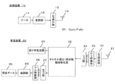
送信装置10は、データ11を変調シンボルにマッピングしてデータシンボルを生成する変調部12、データシンボルにサイクリックプレフィックスを挿入するCP挿入部13と、を備え、生成された送信信号は、送信アンテナ14から送信される。
(First embodiment)
First, the present embodiment will be described with reference to FIG. FIG. 1 shows the case of a SISO system.
The
受信装置20は、受信アンテナ21で受信した受信信号からCPを除去するCP除去部22、シリアル・パラレル変換するS/P変換部23、時間周波数変換するFFT部24、受信したパイロット信号から通信路推定および周波数領域等化を行う通信路推定・周波数領域等化部25、通信路推定値から誤り率を推定する誤り率推定部26、周波数時間変換するIFFT部27、パラレル・シリアル変換するP/S変換部28、復調を行う復調部29と、を備え、受信データ30を生成する。
The
送信装置10ではデータシンボルx(k)にCyclic Prefix (CP)を挿入して送信する。送信信号は周波数選択性フェージング通信路を伝搬し、受信装置20で受信される。受信装置20では受信信号からCPを除去したのち、NポイントのFFTによりN個の周波数成分{R(i),i=0,1,…,N−1}に分解する。R(i)は次式(1)で表される。
The

式(1)に於いて、r(k)はk番目の時間サンプル値である。また、H(i)は第i番目の周波数サンプルに於ける通信路特性、X(i)およびZ(i)はそれぞれ送信信号および雑音の第i番目の周波数成分を表している。各周波数成分にMMSE基準によるFDE重みW(i)を乗算すると、FDE後の時間領域信号のサンプル値r’(k)は次式(2)で表される。 In equation (1), r (k) is the kth time sample value. H (i) represents channel characteristics in the i-th frequency sample, and X (i) and Z (i) represent the i-th frequency component of the transmission signal and noise, respectively. When each frequency component is multiplied by the FDE weight W (i) based on the MMSE standard, the sample value r ′ (k) of the time domain signal after FDE is expressed by the following equation (2).
また、W(i)は、次式(3)である。 W (i) is the following equation (3).
式(2)に於いて、k番目の時間サンプル値であるh’(k)は通信路と等化器を併せたインパルス応答であり、次式(4)で表される。 In equation (2), h '(k), which is the kth time sample value, is an impulse response that combines the channel and the equalizer, and is represented by the following equation (4).
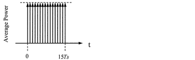
ZF基準のFDEに於いては第i周波数でW(i)H(i)=1となるため、このインパルス応答h’(k)は{h’(k)=0,k≠0}となる(図2)。しかし、MMSE基準のFDEでは必ずしもW(i)H(i)=1ではないため、h’(k)に於いてk≠0なる区間にも値を持つ(図3)。これが符号間干渉として信号判定時に影響する。 In the ZF-based FDE, since W (i) H (i) = 1 at the i-th frequency, this impulse response h ′ (k) is {h ′ (k) = 0, k ≠ 0}. (FIG. 2). However, in the FDE of the MMSE standard, W (i) H (i) = 1 is not necessarily set, and therefore a value also exists in a section where k ≠ 0 in h ′ (k) (FIG. 3). This affects signal determination as intersymbol interference.
式(2)について、データシンボルx(k)にかかる係数を利得とするため、次式(5)のように変形する。 The expression (2) is modified as the following expression (5) in order to use the coefficient for the data symbol x (k) as a gain.
データシンボルx(k)にかかる係数を利得としたため、等価的AWGNの利得Aeqは次式(6)で表される。 Since the coefficient relating to the data symbol x (k) is defined as a gain, the gain A eq of the equivalent AWGN is expressed by the following equation (6).
![]()
![]()
式(4)の第2項をガウス分布と近似することで、式(4)の第2項と第3項の合成の分散を計算し、これを等価的AWGNの平均雑音電力σ2 eqとすると、次式(7)で表される。 By approximating the second term of equation (4) to a Gaussian distribution, the variance of the combination of the second and third terms of equation (4) is calculated, and this is calculated as the average noise power σ 2 eq of the equivalent AWGN Then, it is represented by the following formula (7).
以上に於いて、通信路値H(i)と平均雑音電力値σ2は送受信機で互いに既知であるパイロット信号を用いて測定可能な値とする。通信路値H(i)と平均雑音電力値σ2を用いて、等価的AWGNの利得Aeqと雑音分散σ2 eqが予め算出できれば、Q関数を用いることでBPSK変調又はQPSK変調に於いては次式(8)より受信BERが推定できる。 In the above, the channel value H (i) and the average noise power value σ 2 are values that can be measured using pilot signals that are known to each other by the transceiver. If the gain A eq and noise variance σ 2 eq of the equivalent AWGN can be calculated in advance using the channel value H (i) and the average noise power value σ 2 , the BPSK modulation or the QPSK modulation can be performed using the Q function. The received BER can be estimated from the following equation (8).
![]()
![]()
さて、通信路値と平均雑音電力は受信装置で求める必要があり、次に詳しく述べる。
通信路値を求めるにはそう受信装置で既知のパイロット信号を用いればよい。例えば、各サブキャリアにパイロット信号が配置されているとすると、第i周波数ポイントにおける通信路推定値H^(i)は第i周波数ポイントにおけるパイロット信号P(i)を用いて次式(9)のように求められる。
Now, it is necessary to obtain the channel value and the average noise power by the receiving device, which will be described in detail below.
In order to obtain the channel value, a known pilot signal may be used in the receiving apparatus. For example, assuming that a pilot signal is allocated to each subcarrier, the channel estimation value H ^ (i) at the i-th frequency point is expressed by the following equation (9) using the pilot signal P (i) at the i-th frequency point. It is required as follows.
![]()
![]()
しかし、R(i)には雑音が含まれるため、雑音の影響の抑制と、雑音電力を測定する手法について説明する。まず、H〜(i)をIFFTしてインパルス応答推定値h〜(k)を次式(10)により求める。 However, since noise is included in R (i), a method for suppressing the influence of noise and measuring noise power will be described. First, determined by H ~ (i) an in IFFT impulse response estimate h ~ (k) the following equation (10).
ここで、h(k)は実際のチャネルインパルス応答である。また、z’(k)は複素ガウス雑音であり、P(i)の平均電力が1であれば、z(k)とz’(k)の平均電力は等しくなる。また、h(k)はサンプル番号L−1までしか値のを持たないので、h〜(k)のL−1番目以降の値はz’(k)のみの値となるため、L以降の値を0とし、その後FFTすることで、次式(11)のように雑音電力の影響をL/Nに抑制したチャネル推定値H^(i)が得られる。 Here, h (k) is an actual channel impulse response. Z ′ (k) is complex Gaussian noise. If the average power of P (i) is 1, the average power of z (k) and z ′ (k) is equal. Further, since h (k) has a value only up to the sample number L-1, the values after the (L-1) th of h to (k) are only the values of z '(k). By setting the value to 0 and then performing FFT, a channel estimation value H ^ (i) in which the influence of noise power is suppressed to L / N as shown in the following equation (11) is obtained.
また、雑音の平均電力の測定値σ^2は、次式(12)のように、h〜(k)のL番目以降の平均値より測定できる。 Moreover, the measured value σ ^ 2 of the average power of noise can be measured from the average value after the Lth of h to (k) as in the following equation (12).
誤り率の推定精度を高めるためには、通信路推定誤差を求める必要がある。通信路推定値H^(i)と実際の通信路H(i)の関係式を次式(13)のように表す。 In order to increase the accuracy of error rate estimation, it is necessary to obtain a channel estimation error. The relational expression between the communication channel estimated value H ^ (i) and the actual communication channel H (i) is expressed as the following equation (13).
![]()
![]()
ただし、Z〜(i)は通信路推定誤差である。上式(13)を考慮して等化後の信号を求めると次式(14)のようになる。 However, Z ~ (i) is a channel estimation error. When the equalized signal is obtained in consideration of the above equation (13), the following equation (14) is obtained.
z’’(k)はz’(k)に通信路推定値の雑音が加わったものとなる。z’’(k)がガウス分布すると仮定すると、等価AWGN通信路の最終的な平均雑音電力は次式(15)のように表わされる。 z ″ (k) is obtained by adding the noise of the channel estimation value to z ′ (k). Assuming that z ″ (k) is Gaussian distributed, the final average noise power of the equivalent AWGN channel is expressed by the following equation (15).
(第2実施形態)
本実施形態は送受信側で複数のアンテナを備えるMIMO(Multiple Input Multiple Output)システムにおけるSC−FDEに本発明を適用した例である。なお、送信アンテナ数をnT、受信アンテナ数はnRとする。
(Second Embodiment)
The present embodiment is an example in which the present invention is applied to SC-FDE in a MIMO (Multiple Input Multiple Output) system having a plurality of antennas on the transmission / reception side. It is assumed that the number of transmission antennas is n T and the number of reception antennas is n R.
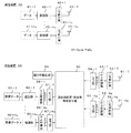
図11は、本実施形態における送信装置、受信装置の構成を示すブロック図である。
送信装置40は、データ41−1〜41−nTを変調シンボルにマッピングしてデータシンボルを生成する変調部42−1〜42−nT、データシンボルにサイクリックプレフィックスを挿入するCP挿入部43−1〜43−nTと、を複数系列備え、生成された複数の送信信号は、複数の送信アンテナ44−1〜44−nTから送信される。
FIG. 11 is a block diagram illustrating a configuration of a transmission device and a reception device in the present embodiment.
The
受信装置50は、各受信アンテナ51−1〜51−nRで受信した受信信号からCPを除去するCP除去部52−1〜52−nR、シリアル・パラレル変換するS/P変換部53−1〜53−nR、時間周波数変換するFFT部54−1〜54−nR、受信したパイロット信号から通信路推定および周波数領域等化を行う通信路推定・周波数領域等化部55、通信路推定値から誤り率を推定する誤り率推定部56、周波数時間変換するIFFT部57−1〜57−nR、パラレル・シリアル変換するP/S変換部58−1〜58−nR、復調を行う復調部59−1〜59−nRと、を備え、受信データ60−1〜60−nRを生成する。
Receiving
以下、数式を用いて詳細な説明を行う。
第i周波数ポイントのnR次元受信信号ベクトルR(i)を次式(16)のように示す。
Hereinafter, detailed description will be given using mathematical expressions.
The n R- dimensional received signal vector R (i) at the i-th frequency point is represented by the following equation (16).
ただし、Rq(i)は第q受信アンテナにおける受信信号、Xp(i)は第p送信アンテナにおける送信信号、Hqp(i)は第p送信アンテナと第q受信アンテナとの間の通信路、Zq(i)は第q受信アンテナにおける雑音である。また上付きのTは転置行列を表す。 Where R q (i) is a received signal at the qth receiving antenna, Xp (i) is a transmitted signal at the pth transmitting antenna, and H qp (i) is a communication path between the pth transmitting antenna and the qth receiving antenna. , Z q (i) is noise in the q-th receiving antenna. Superscript T represents a transposed matrix.
MIMOシステムでは受信信号から送信信号を分離検出するためにMLD(最尤検出:Maximum Likelihood Detection)のような非線形検出方式、ZF(Zero Forcing)やMMSE(最小平均2乗誤差:Minimum Mean Square Error)のような線形検出方式を行う。以下では線形検出方式について説明する。線形検出方式の場合、次式(17)のように受信信号に重み行列W(i)を乗算して送信信号の分離検出を行う。 In a MIMO system, a non-linear detection method such as MLD (Maximum Likelihood Detection), ZF (Zero Forcing) or MMSE (Minimum Mean Square Error) is used to separate and detect transmission signals from received signals. A linear detection method such as Hereinafter, the linear detection method will be described. In the case of the linear detection method, the received signal is detected by separating it by multiplying the received signal by a weight matrix W (i) as shown in the following equation (17).
![]()
![]()
重み行列W(i)はMMSEの場合は次式(18)のようになる。 The weight matrix W (i) is expressed by the following equation (18) in the case of MMSE.
![]()
![]()
ZFの場合は次式(19)のようになる。 In the case of ZF, the following equation (19) is obtained.
![]()
![]()
なお、INはN行N列の単位行列を表す。また、上付きのHは複素共役転置行列を表す。X^(i)の時間領域信号x^(k)は次式(20)のようになる。 Note that IN represents a unit matrix of N rows and N columns. Superscript H represents a complex conjugate transpose matrix. The time domain signal x ^ (k) of X ^ (i) is expressed by the following equation (20).
分離検出後のインパルス応答h’(k)を次式(21)のように表すと、 The impulse response h ′ (k) after separation detection is expressed as in the following equation (21):
x^(k)は次式(22)のようになる。 x ^ (k) is expressed by the following equation (22).
第m送信アンテナ、時刻kの信号に注目すると次式(23)のようになる。 When attention is paid to the m-th transmitting antenna and the signal at time k, the following equation (23) is obtained.
このとき、送信アンテナm、時刻kの等価AWGN利得は次式(24)のようになる。 At this time, the equivalent AWGN gain at the transmitting antenna m and time k is expressed by the following equation (24).
![]()
![]()
また平均雑音電力は次式(25)のようになる。 The average noise power is as shown in the following equation (25).
MIMOシステムでは、SISOシステムの場合にストリーム間干渉成分が新たに雑音として加わることになる。 In the MIMO system, an inter-stream interference component is newly added as noise in the case of the SISO system.
(第3実施形態)
本実施形態は、本発明をOFDM(直交周波数分割多重:Orthogonal Frequency Division Multiplexing)方式に適用した例である。
(Third embodiment)
In the present embodiment, the present invention is applied to an OFDM (Orthogonal Frequency Division Multiplexing) scheme.
OFDMの場合は、各サブキャリアで誤り率を求めることができ、その平均が全体の誤り率とすることができる。周波数領域の受信信号や等化重みはSC−FDEの場合と同様としてよい。従って、第iサブキャリアの等価利得Aeq(i)と平均雑音電力σ2 eq(i)は次式(26)のようになる。 In the case of OFDM, an error rate can be obtained for each subcarrier, and the average can be the overall error rate. The frequency domain received signal and equalization weight may be the same as in SC-FDE. Therefore, the equivalent gain A eq (i) and the average noise power σ 2 eq (i) of the i-th subcarrier are expressed by the following equation (26).
上式を用いて、各サブキャリアの誤り率を求めて、全サブキャリアで平均すれば全体の誤り率を推定することができる。 If the error rate of each subcarrier is obtained using the above equation and averaged over all subcarriers, the overall error rate can be estimated.
(第4実施形態)
本実施形態では、OFDMをMIMOに拡張したMIMO−OFDM方式に本発明を適用した例である。
(Fourth embodiment)
In the present embodiment, the present invention is applied to a MIMO-OFDM system in which OFDM is extended to MIMO.
第iサブキャリアにおける受信信号および重み行列はMIMO−SC−FDEの場合と同様である。このとき、第m送信アンテナ、第iサブキャリアの等価AWGN利得Aeq,m(i)は次式(27)のようになる。 The received signal and the weight matrix in the i-th subcarrier are the same as in MIMO-SC-FDE. At this time, the equivalent AWGN gain A eq, m (i) of the m-th transmission antenna and the i-th subcarrier is expressed by the following equation (27).
また、第m送信アンテナ、第iサブキャリアの平均雑音電力σ2 eq,m(i)は次式(28)のようになる。 Further, the average noise power σ 2 eq, m (i) of the m-th transmission antenna and the i-th subcarrier is expressed by the following equation (28).
ただし、ストリーム間干渉は雑音近似している。このようなAeq,m(i)、σ2 eq,m(i)を用いて各サブキャリアの誤り率を求め、全サブキャリアで平均すれば全体の誤り率を推定することができる。 However, inter-stream interference approximates noise. The error rate of each subcarrier is obtained using such A eq, m (i) and σ 2 eq, m (i) and averaged over all subcarriers, so that the overall error rate can be estimated.
(第5実施形態)
ここでは時間領域にパイロット信号を配置する場合について説明する。通信路値の測定方法は、第1の実施形態と同様に行うことができる。
時間領域にパイロット信号を配置する場合、パイロット信号が周波数領域で一定の振幅を持たず、周波数ポイント毎に変化してしまう。このとき、第i周波数ポイントにおける通信路推定値H^(i)を求める際に、第i周波数ポイントにおけるパイロット信号の振幅が小さい場合、雑音強調を起こし通信路推定精度が劣化してしまう。パイロット信号の振幅が0の場合という極端な場合では通信路推定自体ができなくなってしまう。このためチャネル測定誤差が小さくなるようなパイロット信号を用いる必要がある。このときチャネル推定誤差は、以下の式(29)で表わすことができ、式(29)を小さくするようなパイロット信号を用いればよい。また、以下の式(30)のP(i)は第i周波数ポイントにおけるパイロット信号である。推定誤差の小さいパイロット信号の選び方は、例えば、複数のパイロット信号の候補のうち、式(29)が最小となるものを選べばよい。
(Fifth embodiment)
Here, a case where pilot signals are arranged in the time domain will be described. The channel value measurement method can be performed in the same manner as in the first embodiment.
When a pilot signal is arranged in the time domain, the pilot signal does not have a constant amplitude in the frequency domain and changes for each frequency point. At this time, when the channel estimation value H ^ (i) at the i-th frequency point is obtained, if the amplitude of the pilot signal at the i-th frequency point is small, noise enhancement occurs and the channel estimation accuracy deteriorates. In an extreme case where the amplitude of the pilot signal is 0, the channel estimation itself cannot be performed. For this reason, it is necessary to use a pilot signal that reduces the channel measurement error. At this time, the channel estimation error can be expressed by the following equation (29), and a pilot signal that makes equation (29) small may be used. Further, P (i) in the following equation (30) is a pilot signal at the i-th frequency point. For example, a pilot signal with a small estimation error may be selected by selecting a pilot signal that minimizes Equation (29) from among a plurality of pilot signal candidates.
(第6実施形態)
MIMOシステムの場合、送信アンテナ数に比例して推定すべき通信路も増加する。これらの通信路を独立なリソース(シンボル)を用いて推定しようとすると、送信アンテナ数が増えるに従って、データ信号に対するパイロット信号が増加してしまい、伝送効率の劣化につながってしまう。同一のリソースを用いてMIMOの通信路推定を行う技術について説明する。
(Sixth embodiment)
In the case of a MIMO system, the number of communication paths to be estimated increases in proportion to the number of transmission antennas. If an attempt is made to estimate these communication paths using independent resources (symbols), the pilot signal for the data signal increases as the number of transmission antennas increases, leading to deterioration in transmission efficiency. A technique for performing MIMO channel estimation using the same resource will be described.
例えば、CI(Carrier Interferometry)技術を用いることができる。CI技術は全サブキャリアの振幅・位相を同一とした上で、各サブキャリアで以下の式(31)のように直線位相オフセットを与える。 For example, CI (Carrier Interferometry) technology can be used. In the CI technique, the amplitude and phase of all subcarriers are made the same, and a linear phase offset is given to each subcarrier as shown in the following equation (31).
![]()
![]()
Npは位相オフセット係数を表し、直線の傾きを変化させるものである。周波数領域で直線位相オフセットを与えると、時間領域ではNpに応じた時間シフトとなるので、時間軸上で重ならないように送信アンテナ毎に異なる直線位相オフセット係数を与えれば、同一リソースで各送信アンテナのパイロット信号を多重しても通信路推定値を精度よく求めることができる。また、時間領域でパイロット信号を多重する場合、各送信アンテナで異なる遅延量の巡回遅延を与えれば、周波数領域での直線位相オフセットを与えることと等価となる。例えば、[s1 s2 s3 s4]を遅延量1で巡回遅延させると[s2 s3 s4 s1]となる。 N p represents a phase offset coefficient and changes the slope of the straight line. Giving a linear phase offset in the frequency domain results in a time shift according to N p in the time domain. Even if the pilot signals of the antenna are multiplexed, the channel estimation value can be obtained with high accuracy. Also, when pilot signals are multiplexed in the time domain, providing a cyclic delay with a different delay amount at each transmitting antenna is equivalent to providing a linear phase offset in the frequency domain. For example, when [s1 s2 s3 s4] is cyclically delayed by a delay amount 1, [s2 s3 s4 s1] is obtained.
また、各送信アンテナのパイロット信号を分散配置することによる周波数多重を行って通信路推定することも可能である。分散配置の間隔は等間隔であることが望ましく、分散配置の間隔は送信アンテナ数が増えるに従って大きくなる。8サブキャリアの場合を例に説明する。例えば、送信アンテナ数が2の場合、第1送信アンテナは第1、3、5、7サブキャリアにパイロット信号を配置し、第2送信アンテナは第2、4、6、8サブキャリアにパイロット信号を配置する。各送信アンテナでパイロット信号が配置されていないサブキャリアの通信路推定値を求めるには、配置されたサブキャリアのパイロット信号を用いて、例えば補間を行えばよい。 It is also possible to perform channel estimation by performing frequency multiplexing by distributing pilot signals of each transmitting antenna. The interval of the distributed arrangement is preferably equal, and the interval of the distributed arrangement increases as the number of transmission antennas increases. A case of 8 subcarriers will be described as an example. For example, when the number of transmission antennas is 2, the first transmission antenna places pilot signals on the first, third, fifth and seventh subcarriers, and the second transmission antenna places pilot signals on the second, fourth, sixth and eighth subcarriers. Place. In order to obtain a channel estimation value of a subcarrier on which no pilot signal is arranged at each transmission antenna, for example, interpolation may be performed using the pilot signal of the arranged subcarrier.
なお、CI技術と周波数多重技術を組み合わせることも可能である。分散配置したパイロット信号に直線位相オフセットを与えたものを多重すれば、送信アンテナ数が増えても、分散配置の間隔を小さくすることができ、各アンテナで配置されるパイロット信号数が増えるため、通信路推定精度を向上させることができる。 It is also possible to combine CI technology and frequency multiplexing technology. By multiplexing the pilot signals with a linear phase offset added to the distributed pilot signals, even if the number of transmission antennas increases, the interval of the distributed arrangement can be reduced, and the number of pilot signals arranged at each antenna increases. Communication path estimation accuracy can be improved.
このように上記実施形態では、BERを精度よく推定する方法を示した。これにより、誤り率の高いパケットを破棄する(もしくは後段の受信処理を行うかどうかを選択する)などして伝送の誤りを回避することができる。また、MIMOシステムの場合は、送信アンテナ毎に誤り率の高いパケットを破棄することで、送信アンテナ毎に信頼性の高いデータ伝送を行うことができる。また、全送信アンテナをまとめて破棄するかどうかを判断しても良い。また、破棄するかどうかの選択は例えばQoSによって基準が異なることが望ましく、重要度の高いデータに対しては基準を厳しくし、重要度の低いデータに対しては基準を低く設定すればよい。また、誤り率が悪い環境の場合、信頼性を高めるために伝送レートを下げてもよい。これは送信装置が判断しても良いし、受信装置が送信装置に通知しても良い。 Thus, in the said embodiment, the method of estimating BER accurately was shown. This makes it possible to avoid transmission errors by discarding packets with a high error rate (or selecting whether or not to perform subsequent reception processing). Also, in the case of a MIMO system, highly reliable data transmission can be performed for each transmission antenna by discarding a packet with a high error rate for each transmission antenna. Further, it may be determined whether or not all transmission antennas are discarded together. In addition, it is desirable to select whether or not to discard the criteria, for example, depending on QoS. The criteria may be stricter for data with high importance, and the criteria may be set low for data with low importance. In an environment where the error rate is poor, the transmission rate may be lowered in order to increase reliability. This may be determined by the transmission device, or the reception device may notify the transmission device.
(実施例)
以下、実施例に基づいて本発明の効果を具体的に説明するが、もとより本発明はこれらの実施例に限定されるものではない。
(Example)
Hereinafter, although the effect of the present invention is explained concretely based on an example, the present invention is not limited to these examples from the first.
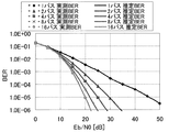
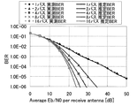
各送信・受信アンテナ間の通信路は、互いに独立な等電力の1、2、4、8、16シンボル時間パスの周波数選択性準静的レイリーフェージング通信路(Quasi-static Rayleigh fading channel)とする。この通信路の遅延プロフィールを図4に示す。
The channel between each transmitting / receiving antenna is a frequency selective quasi-static Rayleigh fading channel of
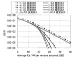
FFTの1ブロックには64シンボル分が含まれる(つまり、N=64)。GI(Guard Interval)長はN/4ポイントとしている。また通信路のチャネル推定は、受信側で完全である場合とパイロット信号により測定した場合とで比較している。 One block of FFT includes 64 symbols (that is, N = 64). The GI (Guard Interval) length is N / 4 points. The channel estimation of the communication channel is compared between the case where the reception side is perfect and the case where measurement is performed using a pilot signal.
アンテナ本数が1×1のSISOシステムについて、図5にチャネル推定が受信側で完全な場合、図6にパイロット信号によりチャネルを測定した場合の、計算機シミュレーションによる誤り率(Bit Error Rate:BER)特性を示す。どの場合もSISOシステム、および2×2、4×4のMIMOシステムについて実施している。図5〜10に於いて、チャネル情報(CSI)と平均受信雑音電力を測定することで、受信BER値の推定を行った。送信パイロット信号により測定されたチャネル情報と受信雑音電力により、等価的なAWGN通信路の利得と雑音分散を計算し、受信BER値の理論式を求めることができ、高い精度でのBER推定が可能であることが確認できた。 For a SISO system with 1 × 1 antennas, when the channel estimation is complete on the receiving side in FIG. 5 and the channel is measured with a pilot signal in FIG. 6, the error rate (Bit Error Rate: BER) characteristics by computer simulation Indicates. In all cases, it is implemented for SISO systems and 2 × 2, 4 × 4 MIMO systems. 5 to 10, the reception BER value was estimated by measuring the channel information (CSI) and the average reception noise power. Based on the channel information and reception noise power measured by the transmission pilot signal, the gain and noise variance of the equivalent AWGN channel can be calculated, and the theoretical expression of the reception BER value can be obtained, and BER estimation with high accuracy is possible. It was confirmed that.
ディジタル無線通信方式に於けるデータ伝送方式に関するものである。特に、SC−FDE方式に対して、リアルタイムかつ高精度なBER推定が可能であり、受信Eb /N0環境に応じて復調方式を切り替えることにより、高信頼度を確保するUEP(Unequal Error Protection)伝送に柔軟に適用できる可能性がある。また、BER推定のMIMOシステム化が簡易な構成で可能となっており、伝送速度の向上と優れたビット誤り率特性を実現させるMIMOディジタル無線通信方式への利用可能性が大きい。 The present invention relates to a data transmission system in a digital wireless communication system. In particular, for the SC-FDE scheme, real-time and high-precision BER estimation is possible, and UEP (Unequal Error Protection that ensures high reliability by switching the demodulation scheme according to the reception E b / N 0 environment. ) There is a possibility that it can be applied flexibly to transmission. Further, the MIMO system for BER estimation can be implemented with a simple configuration, and the applicability to a MIMO digital wireless communication system that realizes an improvement in transmission speed and excellent bit error rate characteristics is great.
10 送信装置
11 データ
12 変調部
13 CP挿入部
14 送信アンテナ
20 受信装置
21 受信アンテナ
22 CP除去部
23 S/P変換部
24 FFT部
25 通信路推定・周波数領域等化部
26 誤り率推定部
27 IFFT部
28 P/S変換部
29 復調部
30 受信データ
40 送信装置
41−1〜41−nT データ
42−1〜42−nT 変調部
43−1〜43−nT 挿入部
44−1〜44−nT 送信アンテナ
50 受信装置
51−1〜51−nR 受信アンテナ
52−1〜52−nR CP除去部
53−1〜53−nR S/P変換部
54−1〜54−nR FFT部
55 通信路推定・周波数領域等化部
56 誤り率推定部
57−1〜57−nR IFFT部
58−1〜58−nR P/S変換部
59−1〜59−nR 復調部
60−1〜60−nR 受信データ
DESCRIPTION OF
Claims (4)
前記通信路推定値と前記平均雑音電力を用いて誤り率を計算する誤り率推定部と、
を備えることを特徴とする受信装置。 A channel estimation unit that estimates a channel using a pilot signal and estimates a channel estimation value and average noise power; and
An error rate estimator that calculates an error rate using the channel estimation value and the average noise power;
A receiving apparatus comprising:
前記通信路推定値と前記平均雑音電力を用いて誤り率を計算する誤り率推定過程と、
を備えることを特徴とする受信方法。 Estimating the channel using the pilot signal, channel estimation and frequency domain equalization process to estimate the channel estimate and average noise power,
An error rate estimation process of calculating an error rate using the channel estimation value and the average noise power;
A receiving method comprising:
Priority Applications (1)
| Application Number | Priority Date | Filing Date | Title |
|---|---|---|---|
| JP2011042022A JP2012124879A (en) | 2010-08-26 | 2011-02-28 | Receiving device and receiving method |
Applications Claiming Priority (5)
| Application Number | Priority Date | Filing Date | Title |
|---|---|---|---|
| JP2010189499 | 2010-08-26 | ||
| JP2010189499 | 2010-08-26 | ||
| JP2010259050 | 2010-11-19 | ||
| JP2010259050 | 2010-11-19 | ||
| JP2011042022A JP2012124879A (en) | 2010-08-26 | 2011-02-28 | Receiving device and receiving method |
Publications (1)
| Publication Number | Publication Date |
|---|---|
| JP2012124879A true JP2012124879A (en) | 2012-06-28 |
Family
ID=46505827
Family Applications (1)
| Application Number | Title | Priority Date | Filing Date |
|---|---|---|---|
| JP2011042022A Pending JP2012124879A (en) | 2010-08-26 | 2011-02-28 | Receiving device and receiving method |
Country Status (1)
| Country | Link |
|---|---|
| JP (1) | JP2012124879A (en) |
Citations (6)
| Publication number | Priority date | Publication date | Assignee | Title |
|---|---|---|---|---|
| JPH10173668A (en) * | 1996-12-09 | 1998-06-26 | Hitachi Ltd | Lan system |
| JP2002319926A (en) * | 2001-02-20 | 2002-10-31 | Lucent Technol Inc | Method to be used for wireless end point and device to be used for wireless systems |
| JP2004282207A (en) * | 2003-03-13 | 2004-10-07 | Kddi Corp | Cnr estimating apparatus, cnr estimating method, cnr estimating program, adaptive transmission wireless system, and wireless apparatus |
| WO2005088884A1 (en) * | 2004-03-11 | 2005-09-22 | Matsushita Electric Industrial Co., Ltd. | Data transmission method and data reception method |
| JP2009152876A (en) * | 2007-12-20 | 2009-07-09 | Sharp Corp | Radio communication system, reception device, and reception method |
| JP2010109611A (en) * | 2008-10-29 | 2010-05-13 | Panasonic Electric Works Co Ltd | Data transmission method and data transmission system |
-
2011
- 2011-02-28 JP JP2011042022A patent/JP2012124879A/en active Pending
Patent Citations (6)
| Publication number | Priority date | Publication date | Assignee | Title |
|---|---|---|---|---|
| JPH10173668A (en) * | 1996-12-09 | 1998-06-26 | Hitachi Ltd | Lan system |
| JP2002319926A (en) * | 2001-02-20 | 2002-10-31 | Lucent Technol Inc | Method to be used for wireless end point and device to be used for wireless systems |
| JP2004282207A (en) * | 2003-03-13 | 2004-10-07 | Kddi Corp | Cnr estimating apparatus, cnr estimating method, cnr estimating program, adaptive transmission wireless system, and wireless apparatus |
| WO2005088884A1 (en) * | 2004-03-11 | 2005-09-22 | Matsushita Electric Industrial Co., Ltd. | Data transmission method and data reception method |
| JP2009152876A (en) * | 2007-12-20 | 2009-07-09 | Sharp Corp | Radio communication system, reception device, and reception method |
| JP2010109611A (en) * | 2008-10-29 | 2010-05-13 | Panasonic Electric Works Co Ltd | Data transmission method and data transmission system |
Non-Patent Citations (3)
| Title |
|---|
| CSNJ201010069527; 小原 辰徳 他: 'Overlap FDEを用いるシングルキャリア伝送のビット誤り率の理論解析' 電子情報通信学会2010年総合大会講演論文集 通信1 PROCEEDINGS OF THE 2010 IEICE GENERAL CONFEREN , 20100302, P.527 * |
| JPN6014043509; 小原 辰徳 他: 'Overlap FDEを用いるシングルキャリア伝送のビット誤り率の理論解析' 電子情報通信学会2010年総合大会講演論文集 通信1 PROCEEDINGS OF THE 2010 IEICE GENERAL CONFEREN , 20100302, P.527 * |
| JPN6015005012; 留場宏道 他: 'マルチキャリア伝送におけるブロック間干渉を抑圧する周波数領域等化' 電子情報通信学会技術研究報告 Vol.105, No.88, 20050519, P.11-15 * |
Similar Documents
| Publication | Publication Date | Title |
|---|---|---|
| JP5122428B2 (en) | Mobile communication system, receiving apparatus and method | |
| US8290462B2 (en) | Receiver and method for estimating a plurality of estimated transfer functions corresponding to wireless channels in a multiple-input system | |
| CN101577692B (en) | Channel estimating method of orthogonal frequency division multiplexing system and device thereof | |
| EP1473862B1 (en) | Apparatus and method for transmitting training symbol groups in an OFDM communications system using multiple antennas | |
| JP4911780B2 (en) | Wireless communication system, receiving apparatus and receiving method | |
| US8570939B2 (en) | Methods and systems for choosing cyclic delays in multiple antenna OFDM systems | |
| CN109600327B (en) | Channel estimation method based on imaginary part interference utilization | |
| JP5579626B2 (en) | Method and system for selecting cyclic delays in a multi-antenna OFDM system | |
| US8411773B2 (en) | Simplified equalization scheme for distributed resource allocation in multi-carrier systems | |
| CN101981845A (en) | MIMO reception device and method | |
| WO2012092642A1 (en) | Doppler-assisted channel estimation | |
| WO2013168792A1 (en) | Wireless reception device, wireless transmission device, wireless communication system, program, and integrated circuit | |
| WO2013018555A1 (en) | Wireless receiving device and program | |
| US8687675B2 (en) | Method and system for transmitting/receiving data in communication system | |
| Bhoyar et al. | Leaky least mean square (LLMS) algorithm for channel estimation in BPSK-QPSK-PSK MIMO-OFDM system | |
| Yin et al. | Design and performance analysis of AFDM with multiple antennas in doubly selective channels | |
| JP2012124879A (en) | Receiving device and receiving method | |
| US9667448B2 (en) | Method and apparatus for channel estimation in wireless communication system | |
| EP2541798A1 (en) | Robust beamforming method and apparatus | |
| JP2012105079A (en) | Radio communication system, transmitter and receiver | |
| Kaur et al. | Investigation on Channel Estimation techniques for MIMO-OFDM System for QAM/QPSK Modulation | |
| Aboutorab et al. | An iterative Doppler-assisted channel estimation for high mobility OFDM systems | |
| D'Amours et al. | Subspace decomposition for channel estimation in SC-FDE systems | |
| Kumari et al. | Greedy Sparse Channel Estimation Framework for Multi-User OTFS Systems | |
| Kavitha et al. | Performance analysis of MISO-OFDM & MIMO-OFDM Systems |
Legal Events
| Date | Code | Title | Description |
|---|---|---|---|
| A621 | Written request for application examination |
Free format text: JAPANESE INTERMEDIATE CODE: A621 Effective date: 20140124 |
|
| A977 | Report on retrieval |
Free format text: JAPANESE INTERMEDIATE CODE: A971007 Effective date: 20141008 |
|
| A131 | Notification of reasons for refusal |
Free format text: JAPANESE INTERMEDIATE CODE: A131 Effective date: 20141014 |
|
| A521 | Written amendment |
Free format text: JAPANESE INTERMEDIATE CODE: A523 Effective date: 20141203 |
|
| A02 | Decision of refusal |
Free format text: JAPANESE INTERMEDIATE CODE: A02 Effective date: 20150210 |