JP2012122604A - Front fork - Google Patents
Front fork Download PDFInfo
- Publication number
- JP2012122604A JP2012122604A JP2011021159A JP2011021159A JP2012122604A JP 2012122604 A JP2012122604 A JP 2012122604A JP 2011021159 A JP2011021159 A JP 2011021159A JP 2011021159 A JP2011021159 A JP 2011021159A JP 2012122604 A JP2012122604 A JP 2012122604A
- Authority
- JP
- Japan
- Prior art keywords
- axle
- side tube
- retainer
- bracket
- tube
- Prior art date
- Legal status (The legal status is an assumption and is not a legal conclusion. Google has not performed a legal analysis and makes no representation as to the accuracy of the status listed.)
- Granted
Links
Images




Landscapes
- Axle Suspensions And Sidecars For Cycles (AREA)
- Fluid-Damping Devices (AREA)
Abstract
【課題】 フロントフォークにおいて、車軸側チューブと車軸ブラケットを簡易かつ高剛性で組立てること。
【解決手段】 フロントフォーク10において、車軸側チューブ12の下端部に被係合部81を設け、車軸側チューブ12の下端部と車軸ブラケット14の凹部15の底面との間に挟み込まれるリテーナ90に、車軸側チューブ12の被係合部81に噛み合う係合部91を設け、車軸ブラケット14に外部から挿入される締結工具によりリテーナ90を回転させ、リテーナ90の係合部91と車軸側チューブ12の被係合部81との噛み合いを介して、車軸側チューブ12の下端部の外周に設けたおねじ部71を車軸ブラケット14の凹部15の内周に設けためねじ部72に螺合させ、車軸側チューブ12の下端部の先端面Aを車軸ブラケット14の凹部15の底面Bの側に衝接させることにより、車軸側チューブ12の下端部が車軸ブラケット14の凹部15に締結されてなるもの。
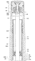
【選択図】 図2PROBLEM TO BE SOLVED: To assemble an axle side tube and an axle bracket in a front fork simply and with high rigidity.
In a front fork, an engaged portion 81 is provided at a lower end portion of an axle side tube 12, and a retainer 90 sandwiched between the lower end portion of the axle side tube 12 and a bottom surface of a concave portion 15 of the axle bracket 14 is provided. The engaging portion 91 that meshes with the engaged portion 81 of the axle side tube 12 is provided, and the retainer 90 is rotated by a fastening tool that is inserted into the axle bracket 14 from the outside, and the engaging portion 91 of the retainer 90 and the axle side tube 12 are rotated. Through the engagement with the engaged portion 81, the male screw portion 71 provided on the outer periphery of the lower end portion of the axle-side tube 12 is screwed to the screw portion 72 to be provided on the inner periphery of the concave portion 15 of the axle bracket 14, By bringing the front end surface A of the lower end portion of the axle side tube 12 into contact with the bottom surface B side of the recess 15 of the axle bracket 14, the lower end portion of the axle side tube 12 becomes the axle bracket. Fastened to the recess 15 of the G14.
[Selection] Figure 2
Description
本発明はフロントフォークに関する。 The present invention relates to a front fork.
自動二輪車等の倒立型フロントフォークでは、車体側チューブに車軸側チューブが摺動可能に挿入され、車体側チューブと車軸側チューブの間に懸架スプリングが介装され、車軸側チューブの下端部が車軸ブラケットの凹部に挿し込み固定されている。 In an inverted front fork such as a motorcycle, an axle tube is slidably inserted into a vehicle body side tube, a suspension spring is interposed between the vehicle body side tube and the axle tube, and the lower end of the axle tube is the axle. It is inserted and fixed in the recess of the bracket.
図7は、特許文献1に記載のフロントフォークを示すものであり、車軸側チューブ1の下端部の外周に設けたおねじ部を車軸ブラケット2の凹部の内周に設けためねじ部に螺着させる。そして、車軸側チューブ1の下端部の先端面を車軸ブラケット2の凹部の底面(又は底面上のスプリングシート3)に衝接させることにより、車軸側チューブ1のおねじ部と車軸ブラケット2のめねじ部を締結し、それらの両ねじ面の接触部に面圧を生じさせ、車軸側チューブ1と車軸ブラケット2を固定する。
FIG. 7 shows a front fork described in Patent Document 1, in which a male thread portion provided on the outer periphery of the lower end portion of the axle-side tube 1 is screwed to the screw portion so as to be provided on the inner periphery of the concave portion of the
図8は、特許文献2に記載のフロントフォークを示すものであり、車軸側チューブ1の下端部に軸方向で連結したボトムホルダ4に、車軸ブラケット2に外部から係入したボルト5を螺着し、車軸側チューブ1を車軸ブラケット2に引き寄せる。そして、車軸側チューブ1の下端部の先端面を車軸ブラケット2の凹部の底面に衝接させ、車軸側チューブ1と車軸ブラケット2を固定する。
FIG. 8 shows a front fork described in
一般に、フロントフォークでは、車軸側チューブ1又は車軸ブラケット2の損傷によりそれらの車軸側チューブ1又は車軸ブラケット2を交換したり、車軸側チューブ1の内部の懸架スプリング6を交換するとき、車軸側チューブ1と車軸ブラケット2を分解、再組立する必要がある。
Generally, in a front fork, when the axle tube 1 or the
しかるに、特許文献1に記載のフロントフォークでは、車軸側チューブ1のおねじ部と車軸ブラケット2のめねじ部を両ねじ面の広い接触部で締結するものであり、車軸側チューブ1と車軸ブラケット2の組立剛性を向上できる。ところが、車軸側チューブ1と車軸ブラケット2をねじ締結するものであるから、車軸側チューブ1と車軸ブラケット2の分解、再組立のために、車軸側チューブ1と車軸ブラケット2のそれぞれを把持する大型の専用工具が必要になる。特に車体側チューブの開口部に設けてあるオイルシールに摺接する車軸側チューブ1の外面についてはキズつけることが許されず、車軸側チューブ1をキズつけずに把持する専用工具が必要になり、高コストである。
However, in the front fork described in Patent Document 1, the male thread portion of the axle-side tube 1 and the female thread portion of the
また、特許文献1に記載のフロントフォークでは、車体側チューブの上端部に取付けたピストンロッドを、車軸側チューブ1の上端部に設けた隔壁部材から車軸側チューブ1の内部に摺動自在に挿入し、このピストンロッドの先端部のピストンに減衰力発生装置を備えている。また、車軸側チューブ1の内部で、ピストンの下端面と、車軸側チューブ1の下端部に設けられるボトムホルダの上端面との間に懸架スプリング6を介装している。このとき、懸架スプリング6や減衰力発生装置等の車軸側チューブ1の内蔵部品を交換保守するときには、車軸側チューブ1の下端部に高剛性でねじ締結されている車軸ブラケット2を容易には取外しできないため、それらの内蔵部品を車軸側から交換保守できない。従って、車軸側チューブ1の上端部に設ける隔壁部材を取外し可能にねじ締結し、それらの内蔵部品を車体側から交換保守する必要があり、コスト高になる。
In the front fork described in Patent Document 1, a piston rod attached to the upper end of the vehicle body side tube is slidably inserted into the axle side tube 1 from a partition member provided at the upper end portion of the axle side tube 1. The piston at the tip of the piston rod is provided with a damping force generator. A suspension spring 6 is interposed between the lower end surface of the piston and the upper end surface of the bottom holder provided at the lower end portion of the axle side tube 1 inside the axle side tube 1. At this time, when replacing and maintaining the built-in components of the axle-side tube 1 such as the suspension spring 6 and the damping force generator, the
他方、特許文献2に記載のフロントフォークでは、一般工具でボルト5をボトムホルダ4に脱着することによって、車軸側チューブ1と車軸ブラケット2を容易に分解、再組立できる。ところが、車軸側チューブ1と車軸ブラケット2は、車軸側チューブ1の下端部の先端面が車軸ブラケット2の凹部の底面に衝接する狭小な接触面だけで締結されるものであり、車軸側チューブ1と車軸ブラケット2の組立剛性が低い。
On the other hand, in the front fork described in
本発明の課題は、フロントフォークにおいて、車軸側チューブと車軸ブラケットを簡易かつ高剛性で組立てることにある。 An object of the present invention is to assemble an axle-side tube and an axle bracket in a front fork simply and with high rigidity.
請求項1に係る発明は、車体側チューブに車軸側チューブが摺動可能に挿入され、車体側チューブと車軸側チューブの間に懸架スプリングが介装され、車軸側チューブの下端部が車軸ブラケットの凹部に挿し込み固定されてなるフロントフォークにおいて、車軸側チューブの下端部に該車軸側チューブの中心軸まわりで一体化されるリテーナを有し、車軸ブラケットに外部から挿入される締結工具によりリテーナを回転させ、リテーナと一体になって回転する車軸側チューブの下端部の外周に設けたおねじ部を車軸ブラケットの凹部の内周に設けためねじ部に螺合させ、車軸側チューブの下端部の先端面を車軸ブラケットの凹部の底面の側に衝接させることにより、車軸側チューブの下端部が車軸ブラケットの凹部に締結されてなるようにしたものである。 In the invention according to claim 1, the axle side tube is slidably inserted into the vehicle body side tube, a suspension spring is interposed between the vehicle body side tube and the axle side tube, and the lower end portion of the axle side tube is the axle bracket. A front fork that is inserted and fixed in a recess has a retainer integrated around the center axis of the axle tube at the lower end of the axle tube, and the retainer is attached to the axle bracket by an externally inserted fastening tool. Rotate and screw the male screw provided on the outer periphery of the lower end of the axle tube that rotates integrally with the retainer into the inner periphery of the recess of the axle bracket, and screw it into the lower end of the axle tube. By bringing the front end surface into contact with the bottom side of the recess of the axle bracket, the lower end of the axle side tube is fastened to the recess of the axle bracket. It is intended.
請求項2に係る発明は、請求項1に係る発明において更に、前記リテーナが、車軸側チューブの下端部と車軸ブラケットの凹部の底面との間に挟み込まれ、車軸側チューブの下端部に設けてある被係合部に該車軸側チューブの中心軸まわりで噛合う係合部を備えてなり、リテーナと車軸側チューブとがそれらの係合部と被係合部との噛合いを介して一体になって回転するようにしたものである。
The invention according to
請求項3に係る発明は、請求項2に係る発明において更に、前記車軸側チューブの下端部の先端面に切欠溝状の被係合部を設け、前記リテーナの外周に突起状の係合部を設けてなるようにしたものである。 According to a third aspect of the present invention, in the second aspect of the invention, a notched groove-like engaged portion is provided on the tip surface of the lower end portion of the axle-side tube, and a protrusion-like engaging portion is provided on the outer periphery of the retainer. Is provided.
請求項4に係る発明は、請求項2又は3に係る発明において更に、前記車軸側チューブの下端部が車軸ブラケットの凹部に締結されるとき、リテーナと車軸ブラケットの凹部の底面との間に弾性体が挟圧されてなるようにしたものである。 According to a fourth aspect of the present invention, in the second or third aspect of the present invention, when the lower end portion of the axle side tube is fastened to the concave portion of the axle bracket, the elastic is provided between the retainer and the bottom surface of the concave portion of the axle bracket. The body is clamped.
請求項5に係る発明は、請求項1に係る発明において更に、前記リテーナが、車軸側チューブの下端部の内周にねじ結合されて一体化されるようにしたものである。 According to a fifth aspect of the invention, in the first aspect of the invention, the retainer is screwed to and integrated with the inner periphery of the lower end portion of the axle side tube.
請求項6に係る発明は、請求項5に係る発明において更に、前記リテーナと車軸側チューブとをねじ結合するねじ山の巻き方向と、車軸側チューブと車軸ブラケットとをねじ結合するねじ山の巻き方向とを逆方向にしてなるようにしたものである。 According to a sixth aspect of the present invention, in the fifth aspect of the present invention, further, a winding direction of a screw thread for screwing the retainer and the axle side tube, and a winding of a screw thread for screwing the axle side tube and the axle bracket. The direction is reversed.
請求項7に係る発明は、請求項5又は6に係る発明において更に、前記リテーナが、車軸側チューブの下端部の端面に当接するとともに、車軸ブラケットの凹部の底面に着座するつば部を備えてなるようにしたものである。 According to a seventh aspect of the invention, in the invention according to the fifth or sixth aspect, the retainer further includes a collar portion that abuts against an end surface of a lower end portion of the axle-side tube and sits on a bottom surface of a concave portion of the axle bracket. It was made to become.
請求項8に係る発明は、請求項1〜7のいずれかに係る発明において更に、前記締結工具が車軸ブラケットに開けた操作孔から挿入され、リテーナに設けてある係合孔との係合を介して該リテーナを回転させるようにしたものである。 The invention according to claim 8 is the invention according to any one of claims 1 to 7, wherein the fastening tool is inserted from an operation hole opened in the axle bracket and engaged with an engagement hole provided in the retainer. The retainer is rotated through the gap.
請求項9に係る発明は、請求項1〜8のいずれかに係る発明において更に、前記車軸側チューブの下端部が車軸ブラケットの凹部に締結されるとき、車軸側チューブの下端部の先端面と車軸ブラケットの凹部の底面との間にワッシャが介装されてなるようにしたものである。 The invention according to a ninth aspect is the invention according to any one of the first to eighth aspects, wherein when the lower end portion of the axle side tube is fastened to the recess of the axle bracket, the tip end surface of the lower end portion of the axle side tube is A washer is interposed between the bottom surface of the concave portion of the axle bracket.
(請求項1)
(a)車軸側チューブの下端部に該車軸側チューブの中心軸まわりで一体化されるリテーナを有する。そして、車軸側チューブと車軸ブラケットとの組立時には、車軸ブラケットに外部から挿入される締結工具によりリテーナを回転させ、リテーナと一体になって回転する車軸側チューブの下端部の外周に設けたおねじ部を車軸ブラケットの凹部の内周に設けためねじ部に螺合させ、車軸側チューブの下端部の先端面を車軸ブラケットの凹部の底面の側(底面又は底面上のワッシャ)に衝接させることにより、車軸側チューブの下端部が車軸ブラケットの凹部に締結される。車軸側チューブのおねじ部と車軸ブラケットのめねじ部の両ねじ面の広い接触部に面圧を生じさせ、車軸側チューブと車軸ブラケットを高剛性で固定できる。
(Claim 1)
(a) A retainer integrated around the central axis of the axle tube is provided at the lower end of the axle tube. When the axle tube and the axle bracket are assembled, the retainer is rotated by a fastening tool inserted from the outside into the axle bracket, and the male screw provided on the outer periphery of the lower end of the axle tube that rotates integrally with the retainer. Since the end is provided on the inner periphery of the recessed portion of the axle bracket, the front end surface of the lower end portion of the axle side tube is brought into contact with the bottom surface side of the recessed portion of the axle bracket (the washer on the bottom surface or the bottom surface). Thus, the lower end portion of the axle side tube is fastened to the recess of the axle bracket. Surface pressure is generated at a wide contact portion between both the male thread portion of the axle side tube and the female thread portion of the axle bracket, and the axle side tube and the axle bracket can be fixed with high rigidity.
(b)締結工具でリテーナを逆回転させれば、車軸側チューブのおねじ部と車軸ブラケットのめねじ部の両ねじ面の接触部の面圧がなくなる仮止め状態になり、車軸側チューブと車軸ブラケットを手回転等で容易に螺動させて分解できる。 (b) If the retainer is rotated in reverse by the fastening tool, the contact pressure between the male threaded part of the axle side tube and the female threaded part of the axle bracket will be temporarily stopped, and the axle side tube The axle bracket can be easily disassembled by screwing it manually.
また、車軸側チューブと車軸ブラケットを手締め等で仮止め状態にした後、締結工具でリテーナを回転させれば、車軸側チューブを車軸ブラケットに容易に再組立できる。 Further, after the axle side tube and the axle bracket are temporarily fixed by hand tightening or the like, the axle side tube can be easily reassembled to the axle bracket by rotating the retainer with a fastening tool.
(c)車軸側チューブを車軸ブラケットに固定するのに、車軸側チューブの少なくとも車体側チューブに挿入される予定部の外面を把持する必要がないから、車体側チューブの開口部に設けてあるオイルシールに摺接する車軸側チューブの外面をキズつけることがなく、品質保証できる。このため、車軸側チューブに車体側チューブが摺動可能に挿入される正立型フロントフォークの製造ラインを共用できる。 (c) In order to fix the axle side tube to the axle bracket, it is not necessary to grip at least the outer surface of the axle side tube to be inserted into the vehicle body side tube. Quality can be assured without scratching the outer surface of the axle-side tube that is in sliding contact with the seal. For this reason, the production line of the upright front fork in which the vehicle body side tube is slidably inserted into the axle side tube can be shared.
(d)車軸側チューブの下端部から車軸ブラケットを容易に分解して取外しできるから、懸架スプリングや減衰力発生装置等の車軸側チューブの内蔵部品を車軸側から交換保守できる。これにより、車軸側チューブの上端部に設けられてピストンロッドが挿入される隔壁部材を、車軸側チューブの上端部に加締め固定でき、コスト低減できる。 (d) Since the axle bracket can be easily disassembled and removed from the lower end of the axle side tube, built-in parts of the axle side tube such as a suspension spring and a damping force generator can be replaced and maintained from the axle side. Thereby, the partition member provided in the upper end part of the axle side tube and into which the piston rod is inserted can be caulked and fixed to the upper end part of the axle side tube, and the cost can be reduced.
(請求項2)
(e)リテーナが、車軸側チューブの下端部と車軸ブラケットの凹部の底面との間に挟み込まれ、車軸側チューブの下端部に設けてある被係合部に該車軸側チューブの中心軸まわりで噛合う係合部を備える。従って、車軸ブラケットに外部から挿入される締結具によりリテーナを回転させるとき、リテーナと車軸側チューブとがそれらの係合部と被係合部との噛合いを介して一体になって回転するものになる。
(Claim 2)
(e) The retainer is sandwiched between the lower end portion of the axle side tube and the bottom surface of the recess of the axle bracket, and is engaged with the engaged portion provided at the lower end portion of the axle side tube around the center axis of the axle side tube. An engaging portion is provided. Therefore, when the retainer is rotated by a fastener inserted from the outside into the axle bracket, the retainer and the axle side tube rotate integrally through the engagement between the engaging portion and the engaged portion. become.
(請求項3)
(f)前記車軸側チューブの下端部の先端面に切欠溝状の被係合部を設け、上述(e)のリテーナの外周に突起状の係合部を設けた。被係合部と係合部を簡易に構成できる。
(Claim 3)
(f) A notched groove-like engaged portion is provided on the distal end surface of the lower end portion of the axle side tube, and a protrusion-like engaging portion is provided on the outer periphery of the retainer described in (e). The engaged portion and the engaging portion can be simply configured.
(請求項4)
(g)前記車軸側チューブの下端部が車軸ブラケットの凹部に締結されるとき、上述(e)のリテーナと車軸ブラケットの凹部の底面との間に弾性体が挟圧される。リテーナを用いた車軸側チューブと車軸ブラケットの組立後、リテーナのガタつきを防止できる。
(Claim 4)
(g) When the lower end portion of the axle side tube is fastened to the recess of the axle bracket, an elastic body is sandwiched between the retainer (e) described above and the bottom surface of the recess of the axle bracket. After assembling the axle side tube and axle bracket using the retainer, it is possible to prevent the retainer from rattling.
(請求項5)
(h)リテーナが、車軸側チューブの下端部の内周にねじ結合(J)されて一体化される。従って、車軸ブラケットに外部から挿入される締結工具によりリテーナを回転させるとき、リテーナが上述のねじ結合Jを介して一体になって回転する。
(Claim 5)
(h) The retainer is screwed (J) and integrated with the inner periphery of the lower end of the axle side tube. Therefore, when the retainer is rotated by a fastening tool inserted from the outside into the axle bracket, the retainer rotates integrally through the above-described screw coupling J.
(請求項6)
(i)上述(h)のリテーナと車軸側チューブとをねじ結合(J)するねじ山の巻き方向と、車軸側チューブと車軸ブラケットとをねじ結合(K)するねじ山の巻き方向とを逆方向にする。従って、車軸ブラケットに外部から挿入される締結工具によりリテーナを回転させるとき、リテーナが上述のねじ結合Jを介して一体になって回転するとともに、このリテーナを一体になって回転する車軸側チューブの外周のおねじ部が上述のねじ結合Kを介して車軸ブラケットの内周のめねじ部に確実に螺合するものになる。
(Claim 6)
(i) The winding direction of the screw thread that joins (J) the retainer and the axle side tube of the above (h) and the winding direction of the screw thread that joins (K) the axle side tube and the axle bracket are reversed. In the direction. Therefore, when the retainer is rotated by the fastening tool inserted from the outside into the axle bracket, the retainer rotates integrally through the above-described screw coupling J, and the retainer rotates integrally with the retainer. The outer peripheral male threaded portion is surely screwed into the inner peripheral female threaded portion of the axle bracket via the screw coupling K described above.
(請求項7)
(j)上述(h)のリテーナが、車軸側チューブの下端部の端面に当接するとともに、車軸ブラケットの凹部の底面に着座するつば部を備える。これにより、車軸側チューブの下端部の先端面が、これに一体化されてなるリテーナのつば部を介して、車軸ブラケットの凹部の底面に衝接するものになり、車軸側チューブの下端部が車軸ブラケットの凹部に締結される。
(Claim 7)
(j) The retainer of (h) described above includes a collar portion that contacts the end surface of the lower end portion of the axle-side tube and sits on the bottom surface of the recess of the axle bracket. As a result, the tip end surface of the lower end portion of the axle-side tube comes into contact with the bottom surface of the recess of the axle bracket via the flange portion of the retainer integrated with the axle-side tube, and the lower end portion of the axle-side tube is Fastened to the recess of the bracket.
(請求項8)
(k)前記締結工具が車軸ブラケットに開けた操作孔から挿入され、リテーナに設けてある係合孔との係合を介して該リテーナを回転させる。締結工具によるリテーナの回転操作構造を簡易に構成できる。
(Claim 8)
(k) The fastening tool is inserted from an operation hole opened in the axle bracket, and the retainer is rotated through engagement with an engagement hole provided in the retainer. The structure for rotating the retainer by the fastening tool can be easily configured.
(請求項9)
(l)前記車軸側チューブの下端部が車軸ブラケットの凹部に締結されるとき、車軸側チューブの下端部の先端面と車軸ブラケットの凹部の底面との間にワッシャが介装される。車軸側チューブが鉄等の硬質材からなり、車軸ブラケットがアルミ合金等の軟質材からなるとき、車軸ブラケットを保護できる。
(Claim 9)
(l) When the lower end portion of the axle side tube is fastened to the recess of the axle bracket, a washer is interposed between the tip surface of the lower end portion of the axle side tube and the bottom surface of the recess of the axle bracket. When the axle side tube is made of a hard material such as iron and the axle bracket is made of a soft material such as an aluminum alloy, the axle bracket can be protected.
(実施例1)(図1〜図6)
フロントフォーク(油圧緩衝器)10は、図1〜図4に示す如く、車体側チューブ11の下端開口部の内周に固定したブッシュ11Aと、車軸側チューブ12の上端開口部の外周に固定したブッシュ12Aを介して、車体側チューブ11の内部に車軸側チューブ12を摺動自在に挿入する倒立型である。車体側チューブ11の下端開口部におけるブッシュ11Aの下部にオイルシール11B、ダストシール11Cが格納される。車体側チューブ11の上端開口部にはフォークボルト13が密封状態で螺着される。車軸側チューブ12の下端部は車軸ブラケット14の環状の長尺凹部15に後述する如くに挿し込み固定される。
Example 1 (FIGS. 1 to 6)
The front fork (hydraulic shock absorber) 10 is fixed to the outer periphery of the upper end opening of the
フロントフォーク10は、車体側チューブ11の内周と、車軸側チューブ12の外周と、前記2つのブッシュ11A、12Aで囲まれる環状油室20を区画する。
The
フロントフォーク10は、車軸側チューブ12の上端側の内周に筒状体31を挿入し、この筒状体31を車軸側チューブ12の上端加締部12Cにより加締め固定する。筒状体31の下端内周に上環状板付カラー32(上環状板33を備える)、下環状板34を順に挿入し、これらを筒状体31の下端加締部31Aにより加締め保持する。筒状体31、上環状板付カラー32及び下環状板34は、車軸側チューブ12の内周に設けられる隔壁部材30を構成し、隔壁部材30より下部に油室21を区画するとともに、上部に油溜室22を区画する。油溜室22の中でその下側領域は油室22A、上側領域は空気室22Bである。
The
フロントフォーク10は、車体側チューブ11の上端部に設けたフォークボルト13の中心軸上の内側面にピストンロッド40の上端面を当て、フォークボルト13の貫通孔に外側から挿入されたボルト40Aがピストンロッド40の中空めねじ部に螺着されてピストンロッド40を引き寄せ、フォークボルト13にピストンロッド40を取付ける。
In the
フロントフォーク10は、車体側チューブ11のフォークボルト13に取付けたピストンロッド40を隔壁部材30から車軸側チューブ12の内部に摺動自在に挿入する。車軸側チューブ12に挿入されたピストンロッド40の先端部には、車軸側チューブ12の内周に摺接するピストン41を備える。ピストンロッド40の先端面に螺着されるボルト42がピストン41の中心孔部に挿着され、ピストン41をピストンロッド40の先端部に固定する。ピストン41の外周にはピストンリング41Aが設けられる。ピストンロッド40のピストン41は、車軸側チューブ12の内部の油室21を、ピストンロッド40が収容されるピストンロッド側油室21Aと、ピストンロッド40が収容されないピストン側油室21Bに区画する。
The
フロントフォーク10は、前記環状油室20を、車軸側チューブ12に設けた油孔20Aを介して、ピストンロッド側油室21Aに連通する。
The
フロントフォーク10は、車軸側チューブ12の内部で、ピストン41のピストン側油室21Bに臨む下端面と、車軸側チューブ12の下端部に設けられているボトムホルダ44のピストン側油室21Bに臨む上端面の間に懸架スプリング43を介装している。フロントフォーク10は、車両走行時に路面から受ける衝撃力を懸架スプリング43の伸縮により吸収する。
The
ボトムホルダ44は車軸側チューブ12の下端部の内径にOリング45を介して密封状態で装填される。ボトムホルダ44は、下端側外周に設けた小径段差部が車軸側チューブ12の下端部の内径の環状溝に係着されている止め輪46に上方から係合することで、車軸側チューブ12の下端部に軸方向で連結される。ボトムホルダ44の上端面は懸架スプリング43のスプリングシート面になる。
The
フロントフォーク10は、ピストン41に減衰力発生装置50を備える。減衰力発生装置50は、図5に示す如く、ピストンロッド側油室21Aとピストン側油室21Bとを連通可能にする伸圧共用流路51をピストン41に備える。そして、ピストン41においてピストンロッド側油室21Aに臨む端面(バルブシート面)に、伸圧共用流路51を開閉するオリフィス付円板バルブ52(オリフィス52A)を添設し、この円板バルブ52をバルブスプリング53、バルブストッパ54によりバックアップする。即ち、ピストン41をボルト42によりピストンロッド40の先端面に固定するとき、ピストンロッド40の先端面とピストン41の上端面との間に、円板バルブ52、バルブスプリング53、バルブストッパ54が挟み保持される。
The
減衰力発生装置50は、伸側行程では、ピストンロッド側油室21Aの高圧油が円板バルブ52のオリフィス52A、伸圧共用流路51を通ってピストン側油室21Bに圧送され、オリフィス52Aの流路抵抗に起因する伸側減衰力を生ずる。圧側行程では、ピストン側油室21Bの高圧油が伸圧共用流路51から円板バルブ52に作用し、円板バルブ52をピストン41の上端面から持ち上げてピストンロッド側油室21Aに圧送され、円板バルブ52がピストン41の上端面との間に形成する隙間の流路抵抗に起因する圧側減衰力を生ずる。
In the extension stroke, the damping
フロントフォーク10は、フォークボルト13の下面に当接するストッパラバー47をピストンロッド40の上端外周まわりに配置し、ピストンロッド40の上端外周に係着した止め輪48Aによりバックアップされるストッパ板48をストッパラバー47の下面に押し当てる。フロントフォーク10の最圧縮時に、車軸側チューブ12の上端加締部12Cがストッパ板48を介してストッパラバー47に衝合することにより、最圧縮ストロークを規制する。
The
フロントフォーク10は、ピストンロッド40の下端外周まわりに配置したリバウンドスプリング49をバルブストッパ54の上面に担持している。フロントフォーク10の最伸長時に、隔壁部材30がリバウンドスプリング49に衝合することにより、最伸長ストロークを規制する。
The
しかるに、フロントフォーク10にあっては、図3に示す如く、車体側チューブ11と車軸側チューブ12の環状隙間からなる前記環状油室20の断面積S1を、ピストンロッド40の断面積(外径に囲まれる面積)S2以上に形成している。
However, in the
また、隔壁部材30は、隔壁チェック弁60を設けている。隔壁チェック弁60は、(A)伸側行程では、環状油室20の断面積S1とピストンロッド40の断面積S2の差ΔSに起因して余剰になる油室21内の油を、ピストンロッド側油室21Aから油溜室22へ排出する微小隙間流路をピストンロッド40まわりに形成し、(B)圧側行程では、環状油室20の断面積S1とピストンロッド40の断面積S2の差ΔSに起因して不足する油を、油溜室22から油室21に補給する流路を形成する。
Further, the
隔壁チェック弁60は、図3に示す如く、隔壁部材30の上環状板33と下環状板34の間に納められ、上環状板33と下環状板34の間隔より短尺とされ、カラー32の内径より小外径とされ、ピストンロッド40の外周との間に微小隙間流路を介して上下変位する円筒状とされ、下端面に横溝61を形成される。隔壁チェック弁60は、下環状板34との間に圧縮コイルばねからなるバルブスプリング62を介装され、上環状板33の側に付勢されている。圧側行程で、車軸側チューブ12に進入するピストンロッド40に連れ移動して下方に移動し、下環状板34に衝合するとともに、上環状板33との間に隙間を形成し、油溜室22の油をその外周経由で横溝61からピストンロッド側油室21Aへ補給可能にする。
As shown in FIG. 3, the
フロントフォーク10は、以下の如くに動作する。
(圧側行程)
車体側チューブ11が車軸側チューブ12に進入し、車体側チューブ11とともに移動するピストン41により収縮されるピストン側油室21Bの油が高圧になり、円板バルブ52を前述の如くに開いてピストンロッド側油室21Aに圧送される結果、前述の如くに圧側減衰力を発生する。
The
(Pressure side stroke)
The vehicle
この圧側行程では、環状油室20の断面積S1とピストンロッド40の断面積S2の差ΔSに起因して環状油室20に補給すべき補給分の油が、油溜室22から隔壁チェック弁60経由でピストンロッド側油室21Aに補給される。
In this pressure side stroke, oil to be replenished to the
(伸側行程)
車体側チューブ11が車軸側チューブ12から退出し、車体側チューブ11とともに移動するピストン41により収縮されるピストンロッド側油室21Aの油が高圧になり、円板バルブ52のオリフィス52Aを通ってピストン側油室21Bに圧送される結果、前述の如くに伸側減衰力を発生する。
(Extension process)
The vehicle
この伸側行程では、環状油室20の断面積S1とピストンロッド40の断面積S2の差ΔSに起因して環状油室20から排出すべき排出分の油が、ピストンロッド側油室21Aから隔壁チェック弁60経由で油溜室22に排出される。
In this extension side stroke, the amount of oil to be discharged from the
しかるに、フロントフォーク10にあっては、車体側チューブ11と車軸側チューブ12を簡易かつ高剛性で組立てるため、車軸側チューブ12の下端部を車軸ブラケット14の凹部15に下記(1)、(2)の如くに挿し込み固定する(図2、図6)。
However, in the
ここで、車軸側チューブ12は下端部の外周におねじ部71が設けられる。また、車軸ブラケット14は車軸側チューブ12の下端部の相当長さ範囲が挿し込まれる相当深さの長尺凹部15を備え、この凹部15の内周にめねじ部72が設けられる。車軸ブラケット14は凹部15の中心軸上に設けられる締結工具(不図示)のための操作孔14Aを外部からその底面にまで開けてある。操作孔14Aはキャップ14Bにより封止される。
Here, the
尚、車軸ブラケット14は図2に示す如く、凹部15の内周の一部に交差する横孔14Cを有し、この横孔14Cに挿着されるストッパボルト16の外周の一部が車軸側チューブ12の外周に設けた環状溝12Dの一部に係合し、車軸側チューブ12を車軸ブラケット14から抜け止めする。車軸側チューブ12のおねじ部71は環状溝12Dよりその先端面A寄りに設けられ、車軸ブラケット14のめねじ部72は横孔14Cより底面B寄りに設けられる。
As shown in FIG. 2, the
そして、車軸側チューブ12の下端部に被係合部81を設ける。更に、車軸側チューブ12の下端部の先端面Aと車軸ブラケット14の凹部15の底面Bとの間に挟み込まれる円板状リテーナ90が設けられ、車軸側チューブ12の被係合部81に該車軸側チューブ12の中心軸まわりで噛み合う係合部91をこのリテーナ90に設ける。本実施例では、車軸側チューブ12の下端部の先端面Aの周方向複数カ所(例えば4カ所)に四角切欠溝状の被係合部81を設ける。リテーナ90の外周の周方向複数カ所(例えば4カ所)に四角突起状の係合部91を設ける。リテーナ90は、車軸ブラケット14の操作孔14Aから挿入される締結工具、例えば六角レンチが係合し得る係合孔92をその中心部に備える。
Then, an engaged
(1)車軸側チューブ12の下端部の外周に設けたおねじ部71を車軸ブラケット14の凹部15の内周に設けためねじ部72に手締め等で螺着し、仮止めする。
(1) Since the
このとき、車軸ブラケット14の凹部15内で、凹部15の底面Bの上に皿ばね座金100を置き、皿ばね座金100の上にリテーナ90を置き、リテーナ90の係合部91を車軸側チューブ12の被係合部81に係入させる。車軸側チューブ12の下端部の内径に装填されて止め輪46に上方から該車軸側チューブ12の軸方向で係合しているボトムホルダ44の下面は、車軸側チューブ12の被係合部81に係入して該車軸側チューブ12の軸方向で被係合部81に突き当たるリテーナ90の上面との間に隙間を介し、リテーナ90と干渉しない。リテーナ90と皿ばね座金100は、車軸ブラケット14の凹部15の内径より僅かに小外径をなし、凹部15の内周に遊挿されるものになる。
At this time, the
(2)車軸ブラケット14の外面を把持具により把持して回り止めした状態で、車軸ブラケット14に外部から挿入される六角レンチ(締結工具)によりリテーナ90を回転させ(六角レンチが車軸ブラケット14に設けた操作孔14Aからその凹部15内に挿入され、リテーナ90に設けてある係合孔92との係合を介して該リテーナ90を回転させる)、リテーナ90の係合部91と車軸側チューブ12の被係合部81との噛み合いを介して該車軸側チューブ12を回転させ、車軸側チューブ12の下端部の外周に設けたおねじ部71を車軸ブラケット14の凹部15の内周に設けためねじ部72に噛み合いさせる。車軸側チューブ12の下端部の先端面Aを、車軸ブラケット14の凹部15の底面Bの側(底面B上の皿ばね座金100)に衝接させることにより、車軸側チューブ12の下端部が車軸ブラケット14の凹部15に締結される。
(2) In a state where the outer surface of the
車軸側チューブ12の下端部が車軸ブラケット14の凹部15に締結されるとき、車軸側チューブ12の下端部の先端面Aと車軸ブラケット14の凹部15の底面Bとの間にワッシャ、本実施例では皿ばね座金100の外周寄り部分が介装される。
When the lower end portion of the
また、車軸側チューブ12の下端部が車軸ブラケット14の凹部15に締結されるとき、リテーナ90の下面と車軸ブラケット14の凹部15の底面Bとの間に弾性体、本実施例では皿ばね座金100の内周寄り部分が挟圧される。
Further, when the lower end portion of the
本実施例によれば以下の作用効果を奏する。
(a)車軸側チューブ12と車軸ブラケット14の組立状態では、車軸ブラケット14に外部から挿入される締結工具によりリテーナ90を回転させ、リテーナ90の係合部91と車軸側チューブ12の被係合部81との噛み合いを介して、車軸側チューブ12の下端部の外周に設けたおねじ部71を車軸ブラケット14の凹部15の内周に設けためねじ部72に螺合させ、車軸側チューブ12の下端部の先端面Aを車軸ブラケット14の凹部15の底面B(又は底面B上のワッシャ(皿ばね座金100))に衝接させることにより、車軸側チューブ12の下端部が車軸ブラケット14の凹部15に締結される。車軸側チューブ12のおねじ部71と車軸ブラケット14のめねじ部72の両ねじ面の広い接触部に面圧を生じさせ、車軸側チューブ12と車軸ブラケット14を高剛性で固定できる。
According to the present embodiment, the following operational effects can be obtained.
(a) In the assembled state of the
(b)締結工具でリテーナ90を逆回転させれば、車軸側チューブ12のおねじ部71と車軸ブラケット14のめねじ部72の両ねじ面の接触部の面圧がなくなる仮止め状態になり、車軸側チューブ12と車軸ブラケット14を手回転等で容易に螺動させて分解できる。
(b) When the
また、車軸側チューブ12と車軸ブラケット14を手締め等で仮止め状態にした後、締結工具でリテーナ90を回転させれば、車軸側チューブ12を車軸ブラケット14に容易に再組立てできる。
Further, after the axle-
(c)車軸側チューブ12を車軸ブラケット14に固定するのに、車軸側チューブ12の外面を把持する必要がないから、車体側チューブの開口部に設けてあるオイルシール11Bに摺接する車軸側チューブ12の外面をキズつけることがなく、品質保証できる。このため、車軸側チューブ12に車体側チューブが摺動可能に挿入される正立型フロントフォーク10の製造ラインを共用できる。
(c) Since it is not necessary to hold the outer surface of the
(d)車軸側チューブ12の下端部から車軸ブラケット14を容易に分解して取外しできるから、懸架スプリング43や減衰力発生装置50等の車軸側チューブ12の内蔵部品を車軸側から交換保守できる。これにより、車軸側チューブ12の上端部に設けられてピストンロッド40が挿入される隔壁部材30を、車軸側チューブ12の上端部に加締め固定でき、コスト低減できる。
(d) Since the
本実施例では、車軸側チューブ12の下端部から車軸ブラケット14を取外した状態で、ボトムホルダ44、懸架スプリング43を車軸側チューブ12の下端開口部から外部との間で着脱できるし、フォークボルト13のボルト40Aから分離されたピストンロッド40及びピストン41(減衰力発生装置50)を車軸側チューブ12の下端開口部から外部との間で着脱できる。
In this embodiment, the
(e)前記車軸側チューブ12の下端部の先端面Aに切欠溝状の被係合部81を設け、前記リテーナ90の外周に突起状の係合部91を設けた。被係合部81と係合部91を簡易に構成できる。
(e) A notched groove-like
(f)前記締結工具が車軸ブラケット14に開けた操作孔14Aから挿入され、リテーナ90に設けてある係合孔92との係合を介して該リテーナ90を回転させる。締結工具によるリテーナ90の回転操作構造を簡易に構成できる。
(f) The fastening tool is inserted from the
(g)前記車軸側チューブ12の下端部が車軸ブラケット14の凹部15に締結されるとき、車軸側チューブ12の下端部の先端面Aと車軸ブラケット14の凹部15の底面Bとの間にワッシャ(皿ばね座金100)が介装される。車軸側チューブ12が鉄等の硬質材からなり、車軸ブラケット14がアルミ合金等の軟質材からなるとき、車軸ブラケット14を保護できる。
(g) When the lower end portion of the
(h)前記車軸側チューブ12の下端部が車軸ブラケット14の凹部15に締結されるとき、リテーナ90と車軸ブラケット14の凹部15の底面Bとの間に弾性体(皿ばね座金100)が挟圧される。リテーナ90を用いた車軸側チューブ12と車軸ブラケット14の組立後、リテーナ90のガタつきを防止できる。
(h) When the lower end portion of the
以上、本発明の実施例を図面により詳述したが、本発明の具体的な構成はこの実施例に限られるものではなく、本発明の要旨を逸脱しない範囲の設計の変更等があっても本発明に含まれる。例えば、車軸側チューブ12の下端部が車軸ブラケット14の凹部15に締結されるとき、車軸側チューブ12の下端部の先端面Aと車軸ブラケット14の凹部15の底面Bとの間に介装されるワッシャと、リテーナ90の下面と車軸ブラケット14の凹部15の底面Bとの間に挟圧される弾性体とは、別部材からなるものでも良い。
The embodiment of the present invention has been described in detail with reference to the drawings. However, the specific configuration of the present invention is not limited to this embodiment, and even if there is a design change or the like without departing from the gist of the present invention. It is included in the present invention. For example, when the lower end portion of the axle-
(実施例2)(図9、図10)
図9、図10に示す実施例2のフロントフォーク10が実施例1におけると異なる点は、ボトムホルダ44及びリテーナ90に代わるリテーナ200を用いたことにある。
Example 2 (FIGS. 9 and 10)
The
リテーナ200は、車軸側チューブ12の下端部の内周にねじ結合(J)されて一体化されるものであり、本実施例では、車軸側チューブ12の下端部(実施例1の被係合部81は設けていない)の平坦な端面Aに当接するとともに、車軸ブラケット14の凹部15の底面Bに着座するつば部201を下端部に備える。
The
リテーナ200は、つば部201の上部の外周におねじ部211を設け、車軸側チューブ12は下端部の内周にめねじ部212を設ける。尚、実施例1におけると同様に、車軸側チューブ12は下端部の外周におねじ部71を設け、車軸ブラケット14の凹部15の内周にめねじ部72を設けている。
The
このとき、リテーナ200と車軸側チューブ12とをねじ結合(J)するおねじ部211とめねじ部212のねじ山の巻き方向と、車軸側チューブ12と車軸ブラケット14とをねじ結合(K)するおねじ部71とめねじ部72のねじ山の巻き方向とを逆方向にしている。即ち、おねじ部211とめねじ部212のねじ結合Jを右ねじにし、おねじ部71とめねじ部72のねじ結合Kを左ねじにする。
At this time, the winding direction of the thread of the male threaded
尚、リテーナ200は実施例1のボトムホルダ44を兼ねるから、つば部201とおねじ部211の間で、車軸側チューブ12の内周に嵌合される外周にOリング202が装填される。そして、リテーナ200の上端面が懸架スプリング43のスプリングシート面になる。
Since the
従って、フロントフォーク10にあっては、車体側チューブ11と車軸側チューブ12を簡易かつ高剛性で組立てるため、車軸側チューブ12の下端部を車軸ブラケット14の凹部15に下記(1)〜(3)の如くに挿し込み固定する。
Therefore, in the
(1)車軸側チューブ12の外周であって、車軸ブラケット14の凹部15に挿し込まれる予定の外面(車体側チューブ11に挿入される予定部以外の外周)を把持具により把持して回り止めし、この車軸側チューブ12の下端部の内周のめねじ部212にリテーナ200のおねじ部211を強固にねじ結合(J)する。これにより、リテーナ200のつば部201が車軸側チューブ12の下端部の端面Aに突き当てられて着座する。
(1) The outer periphery of the axle-
(2)上述(1)によりリテーナ200が結合された車軸側チューブ12の下端部を車軸ブラケット14の凹部15に挿し込み、車軸側チューブ12のおねじ部71を車軸ブラケット14のめねじ部72に手締め等で螺着し、仮止めする。このとき、リテーナ200のつば部201が車軸ブラケット14の凹部15の底面Bに軽く着座する。
(2) The lower end portion of the
(3)車軸ブラケット14の外面を把持具により把持して回り止めした状態で、車軸ブラケット14に外部から挿入される六角レンチ(締結工具)によりリテーナ200を回転させ(六角レンチが車軸ブラケット14に設けた操作孔14Aからその凹部15内に挿入され、リテーナ200に設けてある係合孔203との係合を介して該リテーナ200を回転させる)、リテーナ200と一体になって回転する車軸側チューブ12の下端部の内周に設けたおねじ部71を車軸ブラケット14の凹部15の内周に設けためねじ部72に噛合いさせる。車軸側チューブ12の下端部の先端面Aが、リテーナ200のつば部201を介して、車軸ブラケット14の凹部15の底面Bに衝接するものになり、車軸側チューブ12の下端部が車軸ブラケット14の凹部15に締結される。
(3) In a state where the outer surface of the
本実施例によれば以下の作用効果を奏する。
(a)車軸側チューブ12の下端部に該車軸側チューブ12の中心軸まわりで一体化されるリテーナ200を有する。そして、車軸側チューブ12と車軸ブラケット14との組立時には、車軸ブラケット14に外部から挿入される締結工具によりリテーナ200を回転させ、リテーナ200と一体になって回転する車軸側チューブ12の下端部の外周に設けたおねじ部71を車軸ブラケット14の凹部15の内周に設けためねじ部72に螺合させ、車軸側チューブ12の下端部の先端面Aを車軸ブラケット14の凹部15の底面Bの側(底面B又は底面B上のワッシャ)に衝接させることにより、車軸側チューブ12の下端部が車軸ブラケット14の凹部15に締結される。車軸側チューブ12のおねじ部71と車軸ブラケット14のめねじ部72の両ねじ面の広い接触部に面圧を生じさせ、車軸側チューブ12と車軸ブラケット14を高剛性で固定できる。
According to the present embodiment, the following operational effects can be obtained.
(a) A
(b)リテーナ200が、車軸側チューブ12の下端部の内周にねじ結合(J)されて一体化される。従って、車軸ブラケット14に外部から挿入される締結工具によりリテーナ200を回転させるとき、リテーナ200が上述のねじ結合Jを介して一体になって回転する。
(b) The
(c)上述(b)のリテーナ200と車軸側チューブ12とをねじ結合(J)するねじ山の巻き方向と、車軸側チューブ12と車軸ブラケット14とをねじ結合(K)するねじ山の巻き方向とを逆方向にする。従って、車軸ブラケット14に外部から挿入される締結工具によりリテーナ200を回転させるとき、リテーナ200が上述のねじ結合Jを介して一体になって回転するとともに、このリテーナ200を一体になって回転する車軸側チューブ12の外周のおねじ部71が上述のねじ結合Kを介して車軸ブラケット14の内周のめねじ部72に確実に螺合するものになる。
(c) The direction of winding of the thread for screwing (J) the
(d)上述(b)のリテーナ200が、車軸側チューブ12の下端部の端面Aに当接するとともに、車軸ブラケット14の凹部15の底面Bに着座するつば部201を備える。これにより、車軸側チューブ12の下端部の先端面Aが、これに一体化されてなるリテーナ200のつば部201を介して、車軸ブラケット14の凹部15の底面Bに衝接するものになり、車軸側チューブ12の下端部が車軸ブラケット14の凹部15に締結される。
(d) The
(e)前記締結工具が車軸ブラケット14に開けた操作孔14Aから挿入され、リテーナ200に設けてある係合孔203との係合を介して該リテーナ200を回転させる。締結工具によるリテーナ200の回転操作構造を簡易に構成できる。
(e) The fastening tool is inserted from the
尚、リテーナは、車軸側チューブ12の下端部の内周に直径方向で架け渡されて一体化されるピン301であっても良い(図11)。
The retainer may be a
以上、本発明の実施例を図面により詳述したが、本発明の具体的な構成はこの実施例に限られるものではなく、本発明の要旨を逸脱しない範囲の設計の変更等があっても本発明に含まれる。 The embodiment of the present invention has been described in detail with reference to the drawings. However, the specific configuration of the present invention is not limited to this embodiment, and even if there is a design change or the like without departing from the gist of the present invention. It is included in the present invention.
本発明は、車体側チューブに車軸側チューブが摺動可能に挿入され、車体側チューブと車軸側チューブの間に懸架スプリングが介装され、車軸側チューブの下端部が車軸ブラケットの凹部に挿し込み固定されてなるフロントフォークにおいて、車軸側チューブの下端部に該車軸側チューブの中心軸まわりで一体化されるリテーナを有し、車軸ブラケットに外部から挿入される締結工具によりリテーナを回転させ、リテーナと一体になって回転する車軸側チューブの下端部の外周に設けたおねじ部を車軸ブラケットの凹部の内周に設けためねじ部に螺合させ、車軸側チューブの下端部の先端面を車軸ブラケットの凹部の底面の側に衝接させることにより、車軸側チューブの下端部が車軸ブラケットの凹部に締結されてなるようにした。これにより、フロントフォークにおいて、車軸側チューブと車軸ブラケットを簡易かつ高剛性で組立てることができる。 In the present invention, the axle side tube is slidably inserted into the body side tube, a suspension spring is interposed between the body side tube and the axle side tube, and the lower end of the axle side tube is inserted into the recess of the axle bracket. The fixed front fork has a retainer integrated around the central axis of the axle tube at the lower end of the axle tube, and the retainer is rotated by a fastening tool inserted from the outside into the axle bracket. The external thread provided on the outer periphery of the lower end of the axle side tube that rotates integrally with the screw is screwed to the threaded portion so as to be provided on the inner periphery of the recess of the axle bracket, and the front end surface of the lower end of the axle side tube is The lower end portion of the axle side tube is fastened to the recess portion of the axle bracket by making contact with the bottom surface side of the recess portion of the bracket. Thereby, in the front fork, the axle side tube and the axle bracket can be assembled easily and with high rigidity.
10 フロントフォーク
11 車体側チューブ
12 車軸側チューブ
14 車軸ブラケット
14A 操作孔
15 凹部
43 懸架スプリング
71 おねじ部
72 めねじ部
81 被係合部
90 リテーナ
91 係合部
92 係合孔
100 皿ばね座金(ワッシャ、弾性体)
200 リテーナ
201 つば部
DESCRIPTION OF
200
Claims (9)
車軸側チューブの下端部に該車軸側チューブの中心軸まわりで一体化されるリテーナを有し、
車軸ブラケットに外部から挿入される締結工具によりリテーナを回転させ、リテーナと一体になって回転する車軸側チューブの下端部の外周に設けたおねじ部を車軸ブラケットの凹部の内周に設けためねじ部に螺合させ、車軸側チューブの下端部の先端面を車軸ブラケットの凹部の底面の側に衝接させることにより、車軸側チューブの下端部が車軸ブラケットの凹部に締結されてなることを特徴とするフロントフォーク。 The axle side tube is slidably inserted into the vehicle body side tube, a suspension spring is interposed between the vehicle body side tube and the axle side tube, and the lower end portion of the axle side tube is inserted and fixed in the recess of the axle bracket. In the front fork,
A retainer integrated around the central axis of the axle tube at the lower end of the axle tube;
The retainer is rotated by a fastening tool inserted from the outside into the axle bracket, and the male thread provided on the outer periphery of the lower end of the axle tube that rotates integrally with the retainer is provided on the inner periphery of the recess of the axle bracket. The lower end portion of the axle tube is fastened to the recess of the axle bracket by screwing the end face of the lower end portion of the axle tube to the bottom surface of the recess of the axle bracket. And front fork.
リテーナと車軸側チューブとがそれらの係合部と被係合部との噛合いを介して一体になって回転する請求項1に記載のフロントフォーク。 The retainer is sandwiched between the lower end portion of the axle side tube and the bottom surface of the recess of the axle bracket, and meshes with the engaged portion provided at the lower end portion of the axle side tube around the center axis of the axle side tube. With an engaging part,
The front fork according to claim 1, wherein the retainer and the axle-side tube rotate as a unit through engagement between the engaging portion and the engaged portion.
Priority Applications (2)
| Application Number | Priority Date | Filing Date | Title |
|---|---|---|---|
| JP2011021159A JP5637884B2 (en) | 2010-11-16 | 2011-02-02 | Front fork |
| CN201110184624.XA CN102381419B (en) | 2010-08-30 | 2011-06-28 | front fork |
Applications Claiming Priority (3)
| Application Number | Priority Date | Filing Date | Title |
|---|---|---|---|
| JP2010255808 | 2010-11-16 | ||
| JP2010255808 | 2010-11-16 | ||
| JP2011021159A JP5637884B2 (en) | 2010-11-16 | 2011-02-02 | Front fork |
Publications (2)
| Publication Number | Publication Date |
|---|---|
| JP2012122604A true JP2012122604A (en) | 2012-06-28 |
| JP5637884B2 JP5637884B2 (en) | 2014-12-10 |
Family
ID=46504239
Family Applications (1)
| Application Number | Title | Priority Date | Filing Date |
|---|---|---|---|
| JP2011021159A Active JP5637884B2 (en) | 2010-08-30 | 2011-02-02 | Front fork |
Country Status (1)
| Country | Link |
|---|---|
| JP (1) | JP5637884B2 (en) |
Cited By (9)
| Publication number | Priority date | Publication date | Assignee | Title |
|---|---|---|---|---|
| CN104405820A (en) * | 2014-11-24 | 2015-03-11 | 重庆市亮影工贸有限公司 | Damper connecting body |
| CN104455184A (en) * | 2014-11-24 | 2015-03-25 | 重庆市亮影工贸有限公司 | Motorcycle inversed type front damper |
| CN104455185A (en) * | 2014-11-24 | 2015-03-25 | 重庆市亮影工贸有限公司 | Motorcycle damper |
| CN104595414A (en) * | 2014-11-24 | 2015-05-06 | 重庆市亮影工贸有限公司 | Motorcycle inversion type front shock absorber |
| JP2016070313A (en) * | 2014-09-29 | 2016-05-09 | Kybモーターサイクルサスペンション株式会社 | Front fork |
| WO2018105684A1 (en) * | 2016-12-09 | 2018-06-14 | Kybモーターサイクルサスペンション株式会社 | Front forks |
| JP2019002486A (en) * | 2017-06-15 | 2019-01-10 | Kybモーターサイクルサスペンション株式会社 | Suspension device |
| WO2019150617A1 (en) * | 2018-01-31 | 2019-08-08 | Kyb株式会社 | Hydraulic device |
| JP7431923B1 (en) | 2022-10-24 | 2024-02-15 | カヤバモーターサイクルサスペンション株式会社 | Front fork |
Citations (3)
| Publication number | Priority date | Publication date | Assignee | Title |
|---|---|---|---|---|
| JPH088361Y2 (en) * | 1989-04-04 | 1996-03-06 | カヤバ工業株式会社 | Inverted front fork |
| JP4198579B2 (en) * | 2003-11-27 | 2008-12-17 | カヤバ工業株式会社 | Front fork connection structure |
| JP2009108884A (en) * | 2007-10-26 | 2009-05-21 | Showa Corp | Hydraulic shock absorber |
-
2011
- 2011-02-02 JP JP2011021159A patent/JP5637884B2/en active Active
Patent Citations (3)
| Publication number | Priority date | Publication date | Assignee | Title |
|---|---|---|---|---|
| JPH088361Y2 (en) * | 1989-04-04 | 1996-03-06 | カヤバ工業株式会社 | Inverted front fork |
| JP4198579B2 (en) * | 2003-11-27 | 2008-12-17 | カヤバ工業株式会社 | Front fork connection structure |
| JP2009108884A (en) * | 2007-10-26 | 2009-05-21 | Showa Corp | Hydraulic shock absorber |
Cited By (11)
| Publication number | Priority date | Publication date | Assignee | Title |
|---|---|---|---|---|
| JP2016070313A (en) * | 2014-09-29 | 2016-05-09 | Kybモーターサイクルサスペンション株式会社 | Front fork |
| CN104405820A (en) * | 2014-11-24 | 2015-03-11 | 重庆市亮影工贸有限公司 | Damper connecting body |
| CN104455184A (en) * | 2014-11-24 | 2015-03-25 | 重庆市亮影工贸有限公司 | Motorcycle inversed type front damper |
| CN104455185A (en) * | 2014-11-24 | 2015-03-25 | 重庆市亮影工贸有限公司 | Motorcycle damper |
| CN104595414A (en) * | 2014-11-24 | 2015-05-06 | 重庆市亮影工贸有限公司 | Motorcycle inversion type front shock absorber |
| WO2018105684A1 (en) * | 2016-12-09 | 2018-06-14 | Kybモーターサイクルサスペンション株式会社 | Front forks |
| JP2019002486A (en) * | 2017-06-15 | 2019-01-10 | Kybモーターサイクルサスペンション株式会社 | Suspension device |
| WO2019150617A1 (en) * | 2018-01-31 | 2019-08-08 | Kyb株式会社 | Hydraulic device |
| JP2019132337A (en) * | 2018-01-31 | 2019-08-08 | Kyb株式会社 | Liquid pressure device |
| JP7431923B1 (en) | 2022-10-24 | 2024-02-15 | カヤバモーターサイクルサスペンション株式会社 | Front fork |
| WO2024089992A1 (en) * | 2022-10-24 | 2024-05-02 | カヤバモーターサイクルサスペンション株式会社 | Front fork |
Also Published As
| Publication number | Publication date |
|---|---|
| JP5637884B2 (en) | 2014-12-10 |
Similar Documents
| Publication | Publication Date | Title |
|---|---|---|
| JP5637884B2 (en) | Front fork | |
| EP3786477B1 (en) | Shock absorber | |
| US11400999B2 (en) | Front fork and front fork manufacturing method | |
| US5003839A (en) | Stem having a fixing device | |
| JP2011231796A (en) | Hydraulic shock absorber | |
| US20170268594A1 (en) | Pressure cushioning device | |
| JP5481360B2 (en) | Shock absorber | |
| WO2010109697A1 (en) | Hydraulic buffer | |
| JP2014062584A (en) | Damping force adjustment type shock absorber | |
| JP2005106256A (en) | Suspension device | |
| WO2016047471A1 (en) | Front fork | |
| JP2003083381A (en) | Hydraulic shock absorber tube structure and tube manufacturing method | |
| JP5506525B2 (en) | Hydraulic shock absorber | |
| JP2012047320A (en) | Front fork | |
| CN102381419B (en) | front fork | |
| JP2002323082A (en) | Cylinder type shock absorber in vehicle suspension | |
| US9611914B2 (en) | Adjusting device for a damp adjustment cylinder and a vehicular shock absorber including the same | |
| JP5469592B2 (en) | Shock absorber | |
| JP3222712U (en) | Shock extension bolt | |
| CN102635658A (en) | Hydraulic shock absorber and damping force generator | |
| JP6352662B2 (en) | Suspension device | |
| JP7431923B1 (en) | Front fork | |
| WO2021100499A1 (en) | Shock absorber | |
| JP5562107B2 (en) | Hydraulic shock absorber | |
| CN211449480U (en) | Shock absorber and vehicle |
Legal Events
| Date | Code | Title | Description |
|---|---|---|---|
| A621 | Written request for application examination |
Free format text: JAPANESE INTERMEDIATE CODE: A621 Effective date: 20131127 |
|
| A131 | Notification of reasons for refusal |
Free format text: JAPANESE INTERMEDIATE CODE: A131 Effective date: 20140708 |
|
| A977 | Report on retrieval |
Free format text: JAPANESE INTERMEDIATE CODE: A971007 Effective date: 20140710 |
|
| A521 | Request for written amendment filed |
Free format text: JAPANESE INTERMEDIATE CODE: A523 Effective date: 20140822 |
|
| TRDD | Decision of grant or rejection written | ||
| A01 | Written decision to grant a patent or to grant a registration (utility model) |
Free format text: JAPANESE INTERMEDIATE CODE: A01 Effective date: 20141007 |
|
| A61 | First payment of annual fees (during grant procedure) |
Free format text: JAPANESE INTERMEDIATE CODE: A61 Effective date: 20141021 |
|
| R150 | Certificate of patent or registration of utility model |
Ref document number: 5637884 Country of ref document: JP Free format text: JAPANESE INTERMEDIATE CODE: R150 |
|
| R250 | Receipt of annual fees |
Free format text: JAPANESE INTERMEDIATE CODE: R250 |
|
| R250 | Receipt of annual fees |
Free format text: JAPANESE INTERMEDIATE CODE: R250 |
|
| R250 | Receipt of annual fees |
Free format text: JAPANESE INTERMEDIATE CODE: R250 |
|
| S111 | Request for change of ownership or part of ownership |
Free format text: JAPANESE INTERMEDIATE CODE: R313111 |
|
| R350 | Written notification of registration of transfer |
Free format text: JAPANESE INTERMEDIATE CODE: R350 |
|
| R250 | Receipt of annual fees |
Free format text: JAPANESE INTERMEDIATE CODE: R250 |
|
| R250 | Receipt of annual fees |
Free format text: JAPANESE INTERMEDIATE CODE: R250 |
|
| R250 | Receipt of annual fees |
Free format text: JAPANESE INTERMEDIATE CODE: R250 |
|
| R250 | Receipt of annual fees |
Free format text: JAPANESE INTERMEDIATE CODE: R250 |
|
| R250 | Receipt of annual fees |
Free format text: JAPANESE INTERMEDIATE CODE: R250 |