JP2012118338A - Liquid crystal display device, stereoscopic display system, control program and recording medium - Google Patents
Liquid crystal display device, stereoscopic display system, control program and recording medium Download PDFInfo
- Publication number
- JP2012118338A JP2012118338A JP2010268679A JP2010268679A JP2012118338A JP 2012118338 A JP2012118338 A JP 2012118338A JP 2010268679 A JP2010268679 A JP 2010268679A JP 2010268679 A JP2010268679 A JP 2010268679A JP 2012118338 A JP2012118338 A JP 2012118338A
- Authority
- JP
- Japan
- Prior art keywords
- polarity
- liquid crystal
- polarity inversion
- display device
- crystal display
- Prior art date
- Legal status (The legal status is an assumption and is not a legal conclusion. Google has not performed a legal analysis and makes no representation as to the accuracy of the status listed.)
- Pending
Links
Images


Classifications
-
- G—PHYSICS
- G09—EDUCATION; CRYPTOGRAPHY; DISPLAY; ADVERTISING; SEALS
- G09G—ARRANGEMENTS OR CIRCUITS FOR CONTROL OF INDICATING DEVICES USING STATIC MEANS TO PRESENT VARIABLE INFORMATION
- G09G3/00—Control arrangements or circuits, of interest only in connection with visual indicators other than cathode-ray tubes
- G09G3/001—Control arrangements or circuits, of interest only in connection with visual indicators other than cathode-ray tubes using specific devices not provided for in groups G09G3/02 - G09G3/36, e.g. using an intermediate record carrier such as a film slide; Projection systems; Display of non-alphanumerical information, solely or in combination with alphanumerical information, e.g. digital display on projected diapositive as background
- G09G3/003—Control arrangements or circuits, of interest only in connection with visual indicators other than cathode-ray tubes using specific devices not provided for in groups G09G3/02 - G09G3/36, e.g. using an intermediate record carrier such as a film slide; Projection systems; Display of non-alphanumerical information, solely or in combination with alphanumerical information, e.g. digital display on projected diapositive as background to produce spatial visual effects
-
- G—PHYSICS
- G09—EDUCATION; CRYPTOGRAPHY; DISPLAY; ADVERTISING; SEALS
- G09G—ARRANGEMENTS OR CIRCUITS FOR CONTROL OF INDICATING DEVICES USING STATIC MEANS TO PRESENT VARIABLE INFORMATION
- G09G3/00—Control arrangements or circuits, of interest only in connection with visual indicators other than cathode-ray tubes
- G09G3/20—Control arrangements or circuits, of interest only in connection with visual indicators other than cathode-ray tubes for presentation of an assembly of a number of characters, e.g. a page, by composing the assembly by combination of individual elements arranged in a matrix no fixed position being assigned to or needed to be assigned to the individual characters or partial characters
- G09G3/34—Control arrangements or circuits, of interest only in connection with visual indicators other than cathode-ray tubes for presentation of an assembly of a number of characters, e.g. a page, by composing the assembly by combination of individual elements arranged in a matrix no fixed position being assigned to or needed to be assigned to the individual characters or partial characters by control of light from an independent source
- G09G3/36—Control arrangements or circuits, of interest only in connection with visual indicators other than cathode-ray tubes for presentation of an assembly of a number of characters, e.g. a page, by composing the assembly by combination of individual elements arranged in a matrix no fixed position being assigned to or needed to be assigned to the individual characters or partial characters by control of light from an independent source using liquid crystals
- G09G3/3611—Control of matrices with row and column drivers
- G09G3/3614—Control of polarity reversal in general
Abstract
Description
本発明は、液晶表示装置に関するものであり、特に、立体表示機能を有する液晶表示装置に関する。 The present invention relates to a liquid crystal display device, and more particularly to a liquid crystal display device having a stereoscopic display function.
液晶表示装置は、軽量、薄型および低消費電力等の利点を有しており、携帯電話の表示部等の小型の表示装置としてだけでなく、大型テレビジョンとしても利用されている。一般的な液晶表示装置は平面的な表示を行うが、近年、液晶表示装置を用いて、より臨場感のある立体的な表示を行うことが提案されている(特許文献1参照)。 A liquid crystal display device has advantages such as light weight, thinness, and low power consumption, and is used not only as a small display device such as a display unit of a mobile phone but also as a large television. A general liquid crystal display device performs planar display, but in recent years, it has been proposed to use a liquid crystal display device to perform more realistic three-dimensional display (see Patent Document 1).
特許文献1には、左眼用フレームおよび右眼用フレームを交互に表示する液晶表示装置と、シャッター眼鏡とを備える立体映像表示装置(立体表示システム)が開示されている。観察者は、シャッター眼鏡を装着して液晶表装置の表示画面を観察する。
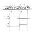
図4は、特許文献1に開示されているフレームデータ及び液晶シャッターの制御方式を示すタイミングチャートである。特許文献1の液晶表示装置では、左眼用映像の表示期間において第1左眼用フレームL1と、第1左眼用フレームL1と同じ映像の第2左眼用フレームL2を順次表示し、右眼用映像の表示期間において第1右眼用フレームR1と、第1右眼用フレームR1と同じ映像の第2右眼用フレームR2を順次表示する。このとき、シャッター眼鏡の左眼シャッターは、液晶シャッタL制御信号108によって、液晶表示装置に第1左眼用フレームL1が書き込まれた後の垂直ブランキング期間205から次の第2左眼用フレームL2の期間まで開いている。また、シャッター眼鏡の右眼シャッターは、液晶シャッタR制御信号109によって、液晶表示装置に第1右眼用フレームR1が書き込まれた後の垂直ブランキング期間205から次の第2右眼用フレームR2の期間まで開いている。
FIG. 4 is a timing chart showing the frame data and liquid crystal shutter control method disclosed in
このように、特許文献1の立体映像表示装置では、観察者が左眼用フレームおよび右眼用フレームを同時に視認するクロストークを防ぐとともに、観察者が左眼用フレームおよび右眼用フレームを視認できる期間を長くしており、これにより、輝度の増加を図っている。
As described above, in the stereoscopic image display apparatus disclosed in
上述したように、特許文献1の立体表示システムでは、1つの左眼用フレーム(左眼画像)のために液晶表示装置は2フレームの表示を行い、1つの右眼用フレーム(右眼画像)のために液晶表示装置は2フレームの表示を行っており、観察者が1つの立体画像を視認するために液晶表示装置は4つのフレームの表示を行う。この場合、観察者が動画表示可能な立体画像を視認するためには、液晶表示装置を高い垂直走査周波数で駆動することが必要となる。このように液晶表示装置を高い垂直走査周波数で駆動する場合、各画素が選択される期間が短くなるため、信号遅延の影響が大きくなり、画素の輝度が所定の値に到達しないことがある。
As described above, in the stereoscopic display system of
そのため、一般的な液晶表示装置の場合は、1フレームごとに画素の極性を反転させるが、画素の輝度を所定の輝度へ到達させるためには、左眼用画像を表示する2フレームの期間、右用画像を表示する2フレームの期間のそれぞれで、画素の極性を同じに保つ必要がある。このように2フレームの期間、画素の極性を同じに保つために、2フレーム周期で画素の極性を反転させた場合、左眼用画像を表示する時の画素の極性、右眼用画像を表示する時の画素の極性それぞれが、変化せずに固定されることになり、左右の画像データによっては画素の焼き付きが発生することがある。 Therefore, in the case of a general liquid crystal display device, the polarity of the pixel is inverted every frame. In order to reach the luminance of the pixel to a predetermined luminance, a period of two frames for displaying the image for the left eye, It is necessary to keep the pixel polarity the same in each of the two frame periods for displaying the right image. Thus, in order to keep the pixel polarity the same for a period of two frames, when the pixel polarity is inverted in a two-frame cycle, the pixel polarity when displaying the left-eye image, the right-eye image is displayed. In this case, the polarities of the pixels are fixed without changing, and pixel burn-in may occur depending on the left and right image data.
これに対し、画素の極性を4フレーム周期で反転させた場合、右眼画像から左眼画像に切り替わる時、もしくは左眼画像から右眼画像に切り替わる時の、どちらか一方の時のみに常に極性反転が行われることになり、左右で画像の見え方が異なってしまう。また、画素の極性を6フレーム以上の周期で反転する場合、それぞれの画素が同じ極性を保つ期間が長いため、フリッカが発生する。 On the other hand, when the polarity of the pixel is inverted at a cycle of 4 frames, the polarity is always changed only when either the right eye image is switched to the left eye image or the left eye image is switched to the right eye image. Inversion will be performed, and the left and right images will look different. In addition, when the polarity of a pixel is inverted at a period of 6 frames or more, flicker occurs because each pixel has a long period of maintaining the same polarity.
図5を参照して具体的に説明する。 This will be specifically described with reference to FIG.
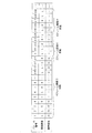
図5(a)は、画素極性を2フレーム毎に反転させた場合の、液晶パネルの各画素の極性を示す図である。また、図5(b)は、画素極性を4フレーム毎に反転させた場合の、液晶パネルの各画素の極性を示す図である。図5(a)および(b)において、マス目の中に書かれた「+」と「−」はそれぞれ画素の極性がプラスの極性とマイナスの極性であることを示しており、列方向および行方向に隣接する画素の極性が互いに異なるように配置されている。 FIG. 5A is a diagram showing the polarity of each pixel of the liquid crystal panel when the pixel polarity is inverted every two frames. FIG. 5B is a diagram illustrating the polarity of each pixel of the liquid crystal panel when the pixel polarity is inverted every four frames. In FIG. 5A and FIG. 5B, “+” and “−” written in the cells indicate that the polarity of the pixel is a positive polarity and a negative polarity, respectively. The pixels adjacent in the row direction are arranged to have different polarities.
図5(a)において、一番左上の画素に着目すると、1フレーム目、2フレーム目、および5フレーム目、6フレーム目、および9フレーム目の左眼画像表示時には、画素の極性は常にプラスを示し、3フレーム目、4フレーム目、及び7フレーム目、8フレーム目では画素の極性は常にマイナスを示す。すなわち、左眼画像表示時におけるそれぞれの画素は、常に同一の極性を示し、右眼画像表示時におけるそれぞれの画素も常に同一の極性を示す。この時、例えば液晶パネルがノーマリブラックのパネルで、右眼画像表示時には前記画素の表示階調が常に最小となるような場合、前記画素は常にプラスの極性の範囲でしか変化しないことになるので、画素の焼き付きが発生してしまう。このように、画素極性を2フレーム周期で反転させ続けた場合、表示する画像データによっては画素の焼き付きが発生することがある。 In FIG. 5A, focusing on the upper left pixel, the polarity of the pixel is always positive when the left eye image is displayed in the first frame, the second frame, the fifth frame, the sixth frame, and the ninth frame. In the third frame, the fourth frame, the seventh frame, and the eighth frame, the pixel polarity is always negative. That is, each pixel at the time of left eye image display always shows the same polarity, and each pixel at the time of right eye image display always shows the same polarity. At this time, for example, if the liquid crystal panel is a normally black panel and the display gradation of the pixel is always minimum when displaying a right-eye image, the pixel always changes only within a positive polarity range. Therefore, pixel burn-in occurs. As described above, when the pixel polarity is continuously inverted at a cycle of two frames, pixel burn-in may occur depending on the image data to be displayed.
また、図5(b)において、一番左上の画素に着目すると、1フレーム目から4フレーム目までは左眼画像、右眼画像共にプラスの極性を示し、5フレーム目から8フレーム目までは左眼画像、右眼画像共にマイナスの極性を示し、9フレーム目で再びプラスの極性に戻っている。画素の極性は、4フレーム目から5フレーム目に変わる時にプラスからマイナスに、および8フレーム目から9フレーム目に変わる時にマイナスからプラスに反転しているが、どちらの場合も右眼画像から左眼画像に切り替わる時に行われていることがわかる。このことから、画素極性を4フレーム周期で反転させ続けた場合、画素極性の反転するタイミングが右眼画像から左眼画像に切り替わる時、もしくは左眼画像から右眼画像に切り替わる時のどちらか一方に固定されることになり、結果として左眼画像と右眼画像の見え方が異なることがある。 In FIG. 5B, when focusing on the upper left pixel, both the left eye image and the right eye image show positive polarity from the first frame to the fourth frame, and from the fifth frame to the eighth frame. Both the left eye image and the right eye image show negative polarity, and return to positive polarity again in the ninth frame. The pixel polarity is inverted from plus to minus when changing from the 4th frame to the 5th frame, and from minus to plus when changing from the 8th frame to the 9th frame. It can be seen that this is done when switching to an eye image. For this reason, when the pixel polarity is continuously inverted at a cycle of 4 frames, either when the pixel polarity is inverted is switched from the right eye image to the left eye image or when the left eye image is switched to the right eye image. As a result, the left eye image and the right eye image may appear differently.
また、一般的なテレビジョン装置の入力映像信号は60fps以下であり、これを左眼用画像で2フレーム、右眼用画像で2フレームの計4フレームに拡張した場合、6フレーム以上で画素極性を反転させる場合は、画素極性の反転周波数は40Hz以下となり、画素極性の反転によるフリッカと呼ばれる表示のちらつき現象が発生する可能性がある。 Also, the input video signal of a general television device is 60 fps or less, and when this is expanded to 4 frames, 2 frames for the left eye image and 2 frames for the right eye image, the pixel polarity is 6 frames or more. When the pixel polarity is inverted, the pixel polarity inversion frequency is 40 Hz or less, and a display flicker phenomenon called flicker may occur due to the pixel polarity inversion.
このように、常に一定の周期で画素極性を反転させると、各画素において、左眼画像表示時おける極性と、右眼画像表示時における極性とが、それぞれ常に一定になるために、画素の焼き付きが発生したり、右眼画像から左眼画像および左眼画像から右眼画像のいずれか一方の切り替え時のみに極性が反転することにより、左眼画像と右眼画像の見え方が異なるといった不都合を生じる。 In this way, if the pixel polarity is always reversed at a constant cycle, the polarity at the time of displaying the left eye image and the polarity at the time of displaying the right eye image are always constant in each pixel. Or the appearance of the left-eye image differs from that of the right-eye image because the polarity is inverted only when the right-eye image is switched to the left-eye image or the left-eye image to the right-eye image. Produce.
本発明は、上記の問題点を解決するためになされたもので、その目的は、画素の焼き付き及び表示ムラの抑制された表示を行うことができる液晶表示装置および立体表示システムを実現することにある。 The present invention has been made to solve the above problems, and an object of the present invention is to realize a liquid crystal display device and a stereoscopic display system capable of performing display with pixel burn-in and display unevenness suppressed. is there.
上記の課題を解決するために、本発明に係る液晶表示装置は、複数の画素を有する液晶パネルと、前記複数の画素の極性を制御する極性制御手段と、を備える液晶表示装置において、前記極性制御手段は、極性を反転させる周期が互いに異なる複数の極性反転形式を有していることを特徴としている。 In order to solve the above problems, a liquid crystal display device according to the present invention includes a liquid crystal panel having a plurality of pixels, and polarity control means for controlling the polarity of the plurality of pixels. The control means is characterized in that it has a plurality of polarity inversion types having different periods for inverting the polarity.
上記の構成によれば、複数の画素の極性を制御する極性制御手段が、極性を反転させる周期が互いに異なる複数の極性反転形式を有している。これにより、各画素において、極性が反転する周期は、常に一定ではなく、変化することとなる。よって、極性が反転する周期が常に一定の場合に比べ、左眼画像表示時おける極性と右眼画像表示時おける極性との比率、および、左眼画像から右眼画像に切り替わる時と、右眼画像から左眼画像に切り替わる時の画素極性の反転頻度の偏りが、低減する。したがって、画素の焼き付き及び表示ムラの抑制された表示を行うことができる液晶表示装置を実現できる。 According to said structure, the polarity control means which controls the polarity of a some pixel has a some polarity inversion form from which the period which reverses a polarity differs mutually. Thereby, in each pixel, the cycle in which the polarity is inverted is not always constant but changes. Therefore, compared to the case where the period of polarity reversal is always constant, the ratio between the polarity when displaying the left eye image and the polarity when displaying the right eye image, and when switching from the left eye image to the right eye image, The bias in the frequency of inversion of the pixel polarity when switching from the image to the left eye image is reduced. Therefore, a liquid crystal display device that can perform display with pixel burn-in and display unevenness can be realized.
本発明に係る液晶表示装置では、前記極性反転形式には、第1の垂直走査期間ごとに極性が反転する第1の極性反転形式が含まれており、前記極性制御手段は、第1の極性反転形式と第1の極性反転形式以外の他の極性反転形式とを交互に切り替え、第1の極性反転形式から第1の極性反転形式以外の他の極性反転形式への切り替えの周期が一定であってもよい。 In the liquid crystal display device according to the present invention, the polarity inversion format includes a first polarity inversion format in which the polarity is inverted every first vertical scanning period, and the polarity control means includes the first polarity The inversion format and other polarity inversion formats other than the first polarity inversion format are alternately switched, and the switching period from the first polarity inversion format to another polarity inversion format other than the first polarity inversion format is constant. There may be.
本発明に係る液晶表示装置では、前記極性反転形式には、第1の垂直走査期間ごとに極性が反転する第1の極性反転形式が含まれており、前記極性制御手段は、第1の極性反転形式と第1の極性反転形式以外の他の極性反転形式とを交互に切り替え、第1の極性反転形式から第1の極性反転形式以外の他の極性反転形式への切り替えの周期が不規則であってもよい。 In the liquid crystal display device according to the present invention, the polarity inversion format includes a first polarity inversion format in which the polarity is inverted every first vertical scanning period, and the polarity control means includes the first polarity The inversion format and other polarity inversion formats other than the first polarity inversion format are alternately switched, and the cycle of switching from the first polarity inversion format to another polarity inversion format other than the first polarity inversion format is irregular It may be.
本発明に係る液晶表示装置では、前記極性制御手段は、各極性制御形式において、極性反転を1回以上行った後、極性反転形式の切り替えを行ってもよい。 In the liquid crystal display device according to the present invention, the polarity control means may perform switching of the polarity inversion format after performing polarity inversion one or more times in each polarity control format.
本発明に係る液晶表示装置では、前記極性反転形式の切り替え順序が規則的であってもよい。 In the liquid crystal display device according to the present invention, the switching order of the polarity inversion type may be regular.
本発明に係る液晶表示装置では、前記極性反転形式の切り替え順序が不規則であってもよい。 In the liquid crystal display device according to the present invention, the switching order of the polarity inversion type may be irregular.
本発明に係る液晶表示装置は、立体表示機能を有し、前記複数の画素に画像を表示するための画像データを書き込む表示信号駆動回路を備え、前記表示信号駆動回路は、立体表示が行われる時に、前記複数の画素のそれぞれに、連続する2垂直走査期間ごとに左眼画像データおよび右眼画像データを交互に書込み、前記極性制御手段は、各画素の極性が、前記左眼画像データの書き込まれる前記2垂直走査期間と、前記右眼画像データの書き込まれる前記2垂直走査期間とのそれぞれにおいて等しくなるように、前記複数の画素の極性を制御することが好ましい。 The liquid crystal display device according to the present invention includes a display signal driving circuit having a stereoscopic display function and writing image data for displaying an image on the plurality of pixels, and the display signal driving circuit performs stereoscopic display. Sometimes, the left eye image data and the right eye image data are alternately written to each of the plurality of pixels every two consecutive vertical scanning periods, and the polarity control means is configured such that each pixel has a polarity of the left eye image data. It is preferable that the polarities of the plurality of pixels are controlled so as to be equal in each of the two vertical scanning periods to be written and the two vertical scanning periods in which the right eye image data is written.
上記の構成によれば、立体表示が行われる時に、前記複数の画素のそれぞれに、連続する2垂直走査期間ごとに左眼画像データおよび右眼画像データが交互に書込まれ、各画素の極性は、左眼画像データの書き込まれる前記2垂直走査期間と、右眼画像データの書き込まれる前記2垂直走査期間とのそれぞれにおいて等しくなる。これにより、観察者が左眼用フレームおよび右眼用フレームを同時に視認するクロストークを防ぐことができる。また、観察者が左眼用フレームおよび右眼用フレームを視認できる期間が長くなるので、輝度の増加を図ることができる。 According to the above configuration, when stereoscopic display is performed, left eye image data and right eye image data are alternately written into each of the plurality of pixels every two consecutive vertical scanning periods, and the polarity of each pixel Is equal in each of the two vertical scanning periods in which the left eye image data is written and the two vertical scanning periods in which the right eye image data is written. Thereby, it is possible to prevent crosstalk in which the observer visually recognizes the left-eye frame and the right-eye frame at the same time. In addition, since the period during which the observer can visually recognize the left-eye frame and the right-eye frame becomes longer, the luminance can be increased.
本発明に係る液晶表示装置では、第1の極性反転形式は、2垂直走査期間ごとに極性が反転する極性反転形式であり、前記他の極性反転形式は、4垂直走査期間ごとに極性が反転する極性反転形式であってもよいし、第1の極性反転形式は、4垂直走査期間ごとに極性が反転する極性反転形式であり、前記他の極性反転形式は、2垂直走査期間ごとに極性が反転する極性反転形式であってもよい。 In the liquid crystal display device according to the present invention, the first polarity inversion format is a polarity inversion format in which the polarity is inverted every two vertical scanning periods, and the other polarity inversion format is the polarity inversion every four vertical scanning periods. The first polarity inversion format is a polarity inversion format in which the polarity is inverted every four vertical scanning periods, and the other polarity inversion format is the polarity every two vertical scanning periods. May be a polarity reversal format in which is reversed.
上記の構成によれば、1フレームで画素極性を反転させる場合に発生する輝度の低下や、6フレーム以上で画素極性を反転させる場合に発生するチラツキを抑えることができる。 According to the above configuration, it is possible to suppress a decrease in luminance that occurs when the pixel polarity is inverted in one frame and flicker that occurs when the pixel polarity is inverted in 6 frames or more.
本発明に係る液晶表示装置では、前記極性制御手段は、前記他の極性反転形式によって極性を制御する場合、極性反転形式の切り替え時の極性反転を含めて極性反転を奇数回行った後、第1の極性反転形式に切り替えることが好ましい。 In the liquid crystal display device according to the present invention, when the polarity control means controls the polarity by the other polarity inversion format, the polarity control means performs the polarity inversion including the polarity inversion at the time of switching the polarity inversion format, It is preferable to switch to the polarity inversion format of 1.
上記の構成によれば、他の極性反転形式に切り替わる前の第1の極性反転形式による極性制御における最初のフレームを、先の先頭フレームとし、他の極性反転形式に切り替わった後の第1の極性反転形式による極性制御における最初のフレームを、後の先頭フレームとすると、第1の極性反転形式および他の極性反転形式がそれぞれ、2垂直走査期間および4垂直走査期間ごとに極性が反転する極性反転形式の場合、先の先頭フレームと後の先頭フレームとでは、視差画像および画素極性のいずれかが異なる。そのため、左眼画像表示時おける極性と右眼画像表示時おける極性との比率の偏りを低減できる。また、第1の極性反転形式および他の極性反転形式がそれぞれ、4垂直走査期間および2垂直走査期間ごとに極性が反転する極性反転形式の場合、画素極性の反転時における切り替え先の視差画像が、他の極性反転形式に切り替わる前の第1の極性反転形式による極性制御時と、他の極性反転形式に切り替わった後の第1の極性反転形式による極性制御時とで異なる。そのため、左眼画像から右眼画像に切り替わる時と、右眼画像から左眼画像に切り替わる時の画素極性の反転頻度の偏りを低減することができる。 According to the above configuration, the first frame in the polarity control by the first polarity inversion format before switching to the other polarity inversion format is set as the first head frame, and the first frame after switching to the other polarity inversion format is used. Assuming that the first frame in polarity control by polarity inversion format is the subsequent first frame, the first polarity inversion format and other polarity inversion formats are polarities whose polarity is inverted every 2 vertical scanning periods and 4 vertical scanning periods, respectively. In the case of the inverted format, either the parallax image or the pixel polarity is different between the first head frame and the second head frame. Therefore, it is possible to reduce the deviation of the ratio between the polarity when displaying the left eye image and the polarity when displaying the right eye image. When the first polarity inversion format and the other polarity inversion format are polarity inversion formats in which the polarity is inverted every 4 vertical scanning periods and 2 vertical scanning periods, respectively, the parallax image to be switched at the time of pixel polarity inversion is The polarity is different between the polarity control in the first polarity inversion format before switching to another polarity inversion format and the polarity control in the first polarity inversion format after switching to another polarity inversion format. Therefore, it is possible to reduce the bias in the inversion frequency of the pixel polarity when switching from the left eye image to the right eye image and when switching from the right eye image to the left eye image.
本発明に係る液晶表示装置では、前記複数の画素は、複数の行および複数の列のマトリクス状に配列されており、前記極性制御手段は、前記複数の画素の全体に前記左眼画像データおよび前記右眼画像データの一方が書き込まれたときに、前記複数の画素のうちの行方向および列方向に隣接する画素の極性が互いに異なるように、前記複数の画素の極性を制御することが好ましい。 In the liquid crystal display device according to the present invention, the plurality of pixels are arranged in a matrix of a plurality of rows and a plurality of columns, and the polarity control means includes the left eye image data and the whole of the plurality of pixels. Preferably, the polarity of the plurality of pixels is controlled such that when one of the right-eye image data is written, the polarities of the pixels adjacent to each other in the row direction and the column direction are different from each other. .
上記の構成によれば、フリッカや輝度ムラを抑えることができる。 According to the above configuration, flicker and luminance unevenness can be suppressed.
本発明に係る液晶表示装置では、前記複数の画素は、複数の行および複数の列のマトリクス状に配列されており、前記極性制御手段は、前記複数の画素の全体に前記左眼画像データおよび前記右眼画像データの一方が書き込まれたときに、前記複数の画素のうちの列方向に隣接する画素の極性が互いに等しくなるように、前記複数の画素の極性を制御してもよい。 In the liquid crystal display device according to the present invention, the plurality of pixels are arranged in a matrix of a plurality of rows and a plurality of columns, and the polarity control means includes the left eye image data and the whole of the plurality of pixels. When one of the right-eye image data is written, the polarity of the plurality of pixels may be controlled so that the polarities of the pixels adjacent in the column direction among the plurality of pixels are equal to each other.
本発明に係る立体表示システムは、上記いずれかの液晶表示装置と、左眼シャッターおよび右眼シャッターを有するシャッター眼鏡とを備え、前記左眼シャッターは、前記左眼画像データの書き込まれる期間に開き、前記右眼シャッターは、前記右眼画像データの書き込まれる期間に開くことを特徴としている。 A stereoscopic display system according to the present invention includes any one of the above-described liquid crystal display devices and shutter glasses having a left eye shutter and a right eye shutter, and the left eye shutter opens during a period in which the left eye image data is written. The right eye shutter is opened during a period in which the right eye image data is written.
上記の構成によれば、液晶表示装置の観察者は映像を立体的に視ることができる。 According to said structure, the observer of a liquid crystal display device can see an image | video in three dimensions.
また、上記液晶表示装置の前記極性制御手段として、コンピュータを動作させる制御プログラム、および当該制御プログラムを記録したコンピュータ読み取り可能な記録媒体も本発明の技術的範囲に含まれる。 Further, as the polarity control means of the liquid crystal display device, a control program for operating a computer and a computer-readable recording medium recording the control program are also included in the technical scope of the present invention.
以上のように、本発明に係る液晶表示装置は、複数の画素を有する液晶パネルと、前記複数の画素の極性を制御する極性制御手段と、を備える液晶表示装置において、前記極性制御手段は、極性を反転させる周期が互いに異なる複数の極性反転形式を有しているので、画素の焼き付き及び表示ムラの抑制された表示を行うことができる液晶表示装置を実現できるという効果を奏する。 As described above, the liquid crystal display device according to the present invention is a liquid crystal display device comprising a liquid crystal panel having a plurality of pixels, and a polarity control means for controlling the polarity of the plurality of pixels. Since a plurality of polarity inversion formats having different periods for reversing the polarity are provided, an effect is obtained that a liquid crystal display device capable of performing display with pixel burn-in and display unevenness suppressed can be realized.
本発明の実施の一形態について図1〜図3に基づいて説明すれば以下のとおりである。 An embodiment of the present invention will be described below with reference to FIGS.
図1は、本実施形態に係る立体表示システム300を示すブロック図である。立体表示システム300は、液晶表示装置100と、シャッター眼鏡280とを備えている。
FIG. 1 is a block diagram showing a stereoscopic display system 300 according to this embodiment. The stereoscopic display system 300 includes the liquid
(液晶表示装置の構成)
液晶表示装置100は、フレームレート制御回路110と、タイミングコントローラー120と、書込状態信号送信回路130と、走査信号駆動回路140と、表示信号駆動回路150と、バックライト駆動回路160と、液晶パネル200と、バックライトユニット250とを備えている。走査信号駆動回路140はゲートドライバとも呼ばれ、表示信号駆動回路150はソースドライバとも呼ばれる。
(Configuration of liquid crystal display device)
The liquid
液晶パネル200は、複数の行および複数の列のマトリクス状に配列された複数の画素を有している。典型的には、画素として赤画素、緑画素および青画素が設けられており、赤画素、緑画素および青画素から構成されたカラー表示画素が任意の色の表示単位として機能する。なお、カラー表示画素は、赤、緑および青画素以外に別の画素(例えば、黄画素)をさらに有してもよい。ここでは図示しないが、液晶パネル200は、前面基板、背面基板、および、それらに挟まれた液晶層を備えている。
The
ここでは、フレームレート60fpsの入力映像信号がフレームレート制御回路110に入力される。例えば、入力映像信号はNTSC信号である。フレームレート制御回路110は入力映像信号に基づいて入力映像信号のフレームレートよりも高いフレームレートの映像信号を生成する。フレームレート制御回路110によって生成される映像信号のフレームレートは所定値となるため、この処理はFRC(Frame Rate Control)とも呼ばれる。一般的なテレビジョン装置で表示される入力映像信号に含まれる1秒あたりのフィールド数は60であり、この入力映像信号のフレームレートは60fps(frames per second)と表記される。
Here, an input video signal having a frame rate of 60 fps is input to the frame
例えば、フレームレート制御回路110は、フレームレート60fpsの入力映像信号に基づいてフレーレート120fpsの映像信号を生成する。液晶表示装置100は、立体表示を行う立体表示モードと、平面表示を行う平面表示モードを有し、立体表示モードの場合、映像信号には立体表示モードで表示されるべき画像データが含まれる。また、平面表示モードの場合、映像信号には平面表示モードで表示されるべき画像データが含まれる。また、映像信号がBD規格等で24pと表される場合、フレームレート制御回路110に入力される前に、例えば、2−3プルダウン変換が行われ、フレームレート制御回路110にはフレームレート60fpsの入力映像信号が入力される。ただし、60fps以外にも50fps、48fps等の映像信号が入力されることもある。
For example, the frame
タイミングコントローラー120は、書込状態信号送信回路130、走査信号駆動回路140、表示信号駆動回路150およびバックライト駆動回路160を制御する。タイミングコントローラー120は、映像信号に基づいて表示信号を生成し、表示信号を表示信号駆動回路150に出力する。映像信号が立体表示モードで表示されるべき画像データを含む場合、タイミングコントローラー120は、左眼用画像データを2フレームに、右眼用画像を2フレームに拡張し、表示信号のフレームレートを240fpsに設定する。この時、1フレーム目の左眼用画像と2フレーム目の左眼用画像、1フレーム目の右眼用画像と2フレーム目の右眼用画像は、それぞれ同じ画像であってもよいし、オーバードライブ駆動等を行うために異なる画像にしてもよい。また、映像信号が平面表示モードで表示されるべき画像データを含む場合、タイミングコントローラー120は表示信号のフレームレートを120fpsに設定する。
The
このように、タイミングコントローラー120は表示モードに応じて表示信号のフレームレートを異ならせる。走査信号駆動回路140は液晶パネル200の書き込みを行う画素を選択する走査信号を供給する。表示信号駆動回路150は液晶パネル200の選択された画素に表示信号を供給する。走査信号駆動回路140および表示信号駆動回路150は表示信号のフレームレートに応じた垂直走査周波数で液晶パネル200を駆動する。このように、タイミングコントローラー120が表示モードに応じて表示信号のフレームレートを異ならせることにより、液晶パネル200の垂直走査周波数を表示モードに応じて異ならせることができる。
Thus, the
本実施形態では、液晶表示装置100は、立体表示機能を有しており、表示信号駆動回路150は、立体表示が行われる時に、複数の画素のそれぞれに、連続する2垂直走査期間ごとに左眼画像データおよび右眼画像データを交互に書込む。
In the present embodiment, the liquid
また、タイミングコントローラー120は極性制御回路121を備えている。極性制御回路121は、液晶パネル200における複数の画素の極性制御を行うための極性制御信号を出力するものであり、特許請求の範囲に記載の極性制御手段に相当する。極性制御の詳細は後述する。
The
書込状態信号送信回路130は、立体表示モードにおける複数の画素の書込状態を示す書込状態信号をシャッター眼鏡280に送信する。
The writing state
(シャッター眼鏡の構成)
シャッター眼鏡280はアクティブメガネとも呼ばれ、左眼シャッターと右眼シャッターを有している。液晶表示装置100が左眼画像を表示する場合は、書込状態信号は左眼画像の表示を示し、シャッター眼鏡280の左眼シャッターが開き、右眼シャッターが閉じる。液晶表示装置100が右眼画像を表示する場合は、書込状態信号は右眼画像の表示を示し、シャッター眼鏡280の右眼シャッターが開き、左眼シャッターが閉じる。このため、シャッター眼鏡280を装着した観察者は液晶表示装置100が表示する左眼用画像を左眼でのみ観測し、右眼用画像を右眼でのみ観測することが可能となる。
(Configuration of shutter glasses)
The shutter glasses 280 are also called active glasses, and have a left eye shutter and a right eye shutter. When the liquid
また、バックライト駆動回路160は、バックライトユニット250を駆動する。これにより、バックライトユニット250は、液晶パネル200の背面から光を照射する。
The
(画素の極性制御)
次に、液晶パネル200における画素の極性制御ついて、図2および図3を参照して説明する。液晶パネル200における複数の画素の極性は、タイミングコントローラー120の極性制御回路121が出力した極性制御信号に基づき、表示信号駆動回路150が前述の複数の画素のそれぞれを駆動することにより、決定される。なお、本実施形態において、画素の極性とは、液晶パネル200の各画素に対して共通に設けられた共通電極の電位を基準とした、画素電極の電位の極性を意味する。
(Pixel polarity control)
Next, pixel polarity control in the
極性制御回路121は、画素の極性が、左眼画像データの書き込まれる2垂直走査期間と、右眼画像データの書き込まれる2垂直走査期間とのそれぞれにおいて等しくなるように、複数の画素の極性を制御する。さらに、極性制御回路121は、極性を反転させる周期が互いに異なる複数の極性反転形式を有している。極性反転形式には、2垂直走査期間ごとに極性が反転する極性反転形式(2フレーム毎の極性反転、第1の極性判定形式)と、4垂直走査期間ごとに極性が反転する極性反転形式(4フレーム毎の極性反転、他の極性判定形式)とが含まれる。
The
まず図2を参照し、2フレーム毎の極性反転を基本動作とし、4フレーム毎の極性反転を合間に挿入する手法について説明する。図2におけるフレーム番号の項目は、現在何フレーム目であるかを示し、視差画像の項目における「L」、「R」の表記はそれぞれ左眼用画像と右眼用画像を表示することを示す。画素極性の項目における「+」、「−」の表記は、液晶パネル200上のある画素に注目した時に、その画素がそれぞれプラス極性であることと、マイナス極性であることを示す。
First, with reference to FIG. 2, a method of inserting polarity inversion every four frames in the interval with polarity inversion every two frames as a basic operation will be described. The item of the frame number in FIG. 2 indicates the current frame number, and “L” and “R” in the parallax image item indicate that the left eye image and the right eye image are displayed, respectively. . In the pixel polarity item, “+” and “−” indicate that when a certain pixel on the
まず1フレーム目からn−1フレーム目までは2フレーム周期で画素極性が反転し、左眼画像のときにはプラス極性、右眼画像の時にはマイナス極性を示すようになっている。次にnフレーム目からn+3フレーム目までの4フレームの期間を同じ極性に保ち、n+4フレーム目以降、再び2フレーム毎に極性を反転するようにしている。 First, from the first frame to the (n-1) th frame, the pixel polarity is inverted in a cycle of two frames, and shows a positive polarity for the left eye image and a negative polarity for the right eye image. Next, the period of 4 frames from the nth frame to the (n + 3) th frame is kept at the same polarity, and the polarity is inverted again every 2 frames after the n + 4th frame.
このことにより、n+4フレーム目以降は左眼画像のときにはマイナス極性、右眼画像の時にはプラス極性を示すようになり、1フレーム目からn−1フレーム目までと左眼画像、右眼画像に対する極性が反転している。すなわち、1フレーム目(先の先頭フレーム)と、n+4フレーム目(後の先頭フレーム)とを比較すると、画素極性が同一である一方、視差画像が異なっている。 As a result, after the n + 4th frame, a negative polarity is shown for the left eye image, and a positive polarity is shown for the right eye image, and the polarity from the first frame to the (n−1) th frame and the left eye image and the right eye image. Is reversed. That is, when the first frame (the first head frame) and the n + 4th frame (the next head frame) are compared, the pixel polarities are the same, but the parallax images are different.
また、図2において、n−2フレーム目からn+1フレーム目まで、4フレームの期間を同じ極性(+極性)に保ち、n+2フレーム目以降、再び2フレーム毎に極性を反転するようにした場合も、n+2フレーム目以降は左眼画像のときにはマイナス極性、右眼画像の時にはプラス極性を示すようになる。すなわち、1フレーム目(先の先頭フレーム)と、n+2フレーム目(後の先頭フレーム)とを比較すると、視差画像が同一である一方、画素極性が異なっている。 In FIG. 2, the period of 4 frames from the (n−2) th frame to the (n + 1) th frame is maintained with the same polarity (+ polarity), and the polarity is reversed again every 2 frames after the (n + 2) th frame. From the n + 2th frame, the negative polarity is displayed for the left eye image, and the positive polarity is displayed for the right eye image. That is, when the first frame (the first head frame) is compared with the n + 2th frame (the next head frame), the parallax images are the same, but the pixel polarities are different.
このように、先の先頭フレームと後の先頭フレームとでは、視差画像および画素極性のいずれかが異なるので、2フレーム毎の極性反転動作を基本の動作とする時には、合間に4フレームでの極性反転を行う極性反転形式を挿入することにより、左眼画像、右眼画像における画素極性の偏りを低減することができる。 As described above, either the parallax image or the pixel polarity is different between the first head frame and the second head frame. Therefore, when the polarity inversion operation every two frames is a basic operation, the polarity of the four frames in between By inserting a polarity reversal format that performs reversal, it is possible to reduce the bias of the pixel polarity in the left eye image and the right eye image.
また、図2では、4フレーム周期の極性反転形式を挿入する際に、極性反転形式の切り替え時の極性反転を含めて1回だけ極性が反転するようになっているが、極性反転形式の切り替え時の極性反転を含めて連続して3回以上の奇数回分4フレーム周期で反転するようにしても、同様に極性の偏りを無くすことができる。すなわち、挿入される極性反転形式では、極性反転形式の切り替え時の極性反転を含めて極性反転を奇数回行った後、極性反転形式を切り替える。これにより、先の先頭フレームと後の先頭フレームとで、視差画像および画素極性のいずれかを異ならせることができるため、左眼画像、右眼画像における画素極性の偏りを低減することができる。 In FIG. 2, when the polarity inversion format with a 4-frame period is inserted, the polarity is inverted only once, including the polarity inversion at the time of switching the polarity inversion format. Even if the polarity is inverted continuously, including inversion of the odd number of 3 times or more for 4 frame periods, the polarity bias can be similarly eliminated. That is, in the polarity reversal format to be inserted, the polarity reversal format is switched after the polarity reversal is performed an odd number of times including the polarity reversal at the time of switching the polarity reversal format. Accordingly, since either the parallax image or the pixel polarity can be made different between the first head frame and the second head frame, it is possible to reduce the bias of the pixel polarity in the left eye image and the right eye image.
次に、図3を参照し、4フレーム毎の極性反転を基本動作とし、2フレーム毎の極性反転を合間に挿入する手法について説明する。 Next, with reference to FIG. 3, a method of inserting polarity inversion every two frames in the interval with polarity inversion every four frames as a basic operation will be described.
まず1フレーム目からn−1フレーム目までは4フレーム周期で画素極性が反転し、画素極性の反転は右眼画像から左眼画像切り替わる時に行われている。次にnフレーム目からn+1フレーム目までの2フレームの期間を同じ極性に保ち、n+2フレーム目以降、再び4フレーム毎に極性が反転するようにしている。このことにより、n+2フレーム以降は、左眼画像から右眼画像に切り替わる時に画素極性の反転が行われることになり、1フレーム目からn−1フレーム目までとは逆の関係になっている。 First, from the first frame to the (n−1) th frame, the pixel polarity is inverted at a cycle of 4 frames, and the pixel polarity is inverted when the right eye image is switched to the left eye image. Next, the period of 2 frames from the nth frame to the (n + 1) th frame is maintained at the same polarity, and the polarity is reversed again every 4th frame after the n + 2th frame. As a result, after the n + 2 frame, the pixel polarity is inverted when the left eye image is switched to the right eye image, and the relationship from the first frame to the (n−1) th frame is reversed.
また、図3において、n−4フレーム目からn−3フレーム目までの2フレームの期間を同じ極性(プラス極性)に保ち、n−2フレーム目以降、再び4フレーム毎に極性が反転するようにした場合も、n−2フレーム目以降は、左眼画像から右眼画像に切り替わる時に画素極性の反転が行われる。 In FIG. 3, the period of 2 frames from the n-4th frame to the n-3th frame is kept at the same polarity (plus polarity), and the polarity is reversed every 4th frame after the n-2th frame. Also in the case of, the pixel polarity is inverted when switching from the left-eye image to the right-eye image after the (n-2) th frame.
このように4フレーム毎の極性反転動作を基本の動作とする時には、合間に2フレームでの極性反転を挿入することにより、画素の極性反転タイミングにおける右眼画像、左眼画像の偏りを低減することができる。 As described above, when the polarity reversal operation every four frames is a basic operation, the polarity reversal of the right eye image and the left eye image at the polarity reversal timing of the pixels is reduced by inserting the polarity reversal in 2 frames in between. be able to.
図3では、2フレーム周期の極性反転形式を挿入する際に、極性反転形式の切り替え時の極性反転を含めて1回だけ極性が反転するようになっているが、極性反転形式の切り替え時の極性反転を含めて連続して3回以上の奇数回分2フレーム周期で反転するようにしても、同様に極性の偏りを低減することができる。 In FIG. 3, when inserting the polarity inversion format of the two-frame period, the polarity is inverted only once including the polarity inversion at the time of switching the polarity inversion format. Even if the polarity is inverted continuously in two frame periods of 3 or more odd times including polarity inversion, the polarity bias can be similarly reduced.
図2および図3において、基本となる極性反転周期以外での他の極性反転形式を挿入するタイミングは、定期的にあらかじめ決められたフレームごとに挿入してもよいし、ランダムに挿入してもよい。すなわち、基本となる極性反転形式から他の極性反転形式への切り替えの周期は、一定であってもよいし不規則であってもよい。 In FIG. 2 and FIG. 3, the timing of inserting other polarity inversion formats other than the basic polarity inversion cycle may be periodically inserted every predetermined frame or randomly. Good. That is, the period of switching from the basic polarity inversion format to another polarity inversion format may be constant or irregular.
他の極性反転形式をランダムに挿入する手法としては、タイミングコントローラー120のROMやレジスタなどに乱数列を格納しておき、それに基づいて乱数を発生させることによりランダムなパターンを発生させる方法や、タイミングコントローラー120内にLFSR(Linear Feedback Shift Register)に代表される乱数発生回路を設け、乱数発生回路により生成された乱数列に基づいてランダムなパターンを発生させる方法がある。
As a method of inserting other polarity inversion formats at random, a method of generating a random pattern by storing a random number sequence in a ROM or a register of the
(極性制御の変形例)
また、基本となる画素極性の反転周期を特に定めずに、複数種類の反転周期を切り替えることによっても極性の偏りを無くすことが可能となる。すなわち、複数の極性反転形式の切り替え順序が不規則であってもよい。例えば、前記のいずれかの乱数列生成手法を用いて1bit単位の乱数値を生成し、乱数値が0ならば4フレームで画素極性を反転し、乱数値が1ならば2フレームで画素極性を反転するというように割り当て、画素極性が反転するたびに乱数値を更新するようにすれば、画素極性の偏りを無くすことができる。この場合、各極性制御形式において、極性反転形式の切り替え時の極性反転を含めて極性反転を1回以上行った後、極性反転形式の切り替えを行うことが好ましい。
(Modification of polarity control)
In addition, it is possible to eliminate the polarity bias by switching a plurality of types of inversion periods without defining the basic inversion period of the pixel polarity. That is, the switching order of the plurality of polarity inversion types may be irregular. For example, one of the random number generation methods described above is used to generate a 1-bit random value. If the random value is 0, the pixel polarity is inverted in 4 frames. If the random value is 1, the pixel polarity is changed in 2 frames. If the random number is updated every time the pixel polarity is reversed and assigned so as to be reversed, the bias of the pixel polarity can be eliminated. In this case, in each polarity control format, it is preferable to perform polarity reversal switching after performing polarity reversal one or more times including polarity reversal when switching the polarity reversal.
なお、複数の極性反転形式の切り替え順序が規則的であってもよい。 Note that the switching order of the plurality of polarity inversion types may be regular.
また、本実施形態では、極性制御回路121が、2垂直走査期間ごとに極性が反転する極性反転形式と、4垂直走査期間ごとに極性が反転する極性反転形式とを有していたが、これに限定されず、1垂直走査期間ごとに極性が反転する極性反転形式や、6垂直走査期間ごとに極性が反転する極性反転形式を有していてもよい。
In the present embodiment, the
いずれの方法で基本となる極性反転周期以外での極性反転周期を挿入する場合でも、(1)左眼画像表示時におけるプラス極性とマイナス極性の発生比率、(2)右眼画像表示時におけるプラス極性とマイナス極性の発生比率、(3)画像表示期間全体のプラス極性とマイナス極性の発生比率、および(4)左眼画像から右眼画像に切り替わる時と、右眼画像から左眼画像に切り替わる時の画素極性の反転頻度に偏りがないようにすることが望ましい。 Even when a polarity reversal period other than the basic polarity reversal period is inserted by any method, (1) the generation ratio of the positive polarity and the negative polarity when displaying the left eye image, and (2) the plus when displaying the right eye image. Polarity and negative polarity generation ratio, (3) positive and negative polarity generation ratio of the entire image display period, and (4) when switching from the left eye image to the right eye image, and switching from the right eye image to the left eye image. It is desirable that there is no bias in the frequency of pixel polarity reversal.
本実施形態では、表示信号駆動回路150は、立体表示が行われる時に、複数の画素のそれぞれに、連続する2垂直走査期間ごとに左眼画像データおよび右眼画像データを交互に書込む構成であったが、1垂直走査期間ごとに左眼画像データおよび右眼画像データを交互に書込む構成であってもよい。
In the present embodiment, the display
本実施形態では、極性制御回路121は、複数の画素の全体に左眼画像データおよび右眼画像データの一方が書き込まれたときに、複数の画素のうちの行方向および列方向に隣接する画素の極性が互いに異なるように、複数の画素の極性を制御する構成であったが、これに限定されない。例えば、極性制御回路121は、複数の画素の全体に左眼画像データおよび右眼画像データの一方が書き込まれたときに、複数の画素のうちの列方向に隣接する画素の極性が互いに等しくなるように、複数の画素の極性を制御してもよい。
In the present embodiment, the
(ソフトウェアによる本発明の実施)
また、上述した液晶表示装置100の各ブロック、特に極性制御回路121は、ハードウェアロジックによって構成してもよいし、次のようにCPUを用いてソフトウェアによって実現してもよい。
(Implementation of the present invention by software)
Further, each block of the liquid
すなわち、液晶表示装置100は、各機能を実現する制御プログラムの命令を実行するCPU(central processing unit)、上記プログラムを格納したROM(read only memory)、上記プログラムを展開するRAM(random access memory)、上記プログラムおよび各種データを格納するメモリ等の記憶装置(記録媒体)などを備えている。そして、本発明の目的は、上述した機能を実現するソフトウェアである液晶表示装置100の制御プログラムのプログラムコード(実行形式プログラム、中間コードプログラム、ソースプログラム)をコンピュータで読み取り可能に記録した記録媒体を、上記液晶表示装置100に供給し、そのコンピュータ(またはCPUやMPU)が記録媒体に記録されているプログラムコードを読み出し実行することによっても、達成可能である。
That is, the liquid
上記記録媒体としては、例えば、磁気テープやカセットテープ等のテープ系、フロッピー(登録商標)ディスク/ハードディスク等の磁気ディスクやCD−ROM/MO/MD/DVD/CD−R等の光ディスクを含むディスク系、ICカード(メモリカードを含む)/光カード等のカード系、あるいはマスクROM/EPROM/EEPROM/フラッシュROM等の半導体メモリ系などを用いることができる。 Examples of the recording medium include a tape system such as a magnetic tape and a cassette tape, a magnetic disk such as a floppy (registered trademark) disk / hard disk, and an optical disk such as a CD-ROM / MO / MD / DVD / CD-R. Card system such as IC card, IC card (including memory card) / optical card, or semiconductor memory system such as mask ROM / EPROM / EEPROM / flash ROM.
また、液晶表示装置100を通信ネットワークと接続可能に構成し、上記プログラムコードを、通信ネットワークを介して供給してもよい。この通信ネットワークとしては、特に限定されず、例えば、インターネット、イントラネット、エキストラネット、LAN、ISDN、VAN、CATV通信網、仮想専用網(virtual private network)、電話回線網、移動体通信網、衛星通信網等が利用可能である。また、通信ネットワークを構成する伝送媒体としては、特に限定されず、例えば、IEEE1394、USB、電力線搬送、ケーブルTV回線、電話線、ADSL回線等の有線でも、IrDAやリモコンのような赤外線、Bluetooth(登録商標)、802.11無線、HDR(high data rate)、携帯電話網、衛星回線、地上波デジタル網等の無線でも利用可能である。なお、本発明は、上記プログラムコードが電子的な伝送で具現化された、搬送波に埋め込まれたコンピュータデータ信号の形態でも実現され得る。
Further, the liquid
(付記事項)
本発明は上述した実施形態に限定されるものではなく、請求項に示した範囲で種々の変更が可能である。すなわち、請求項に示した範囲で適宜変更した技術的手段を組み合わせて得られる実施形態についても本発明の技術的範囲に含まれる。
(Additional notes)
The present invention is not limited to the above-described embodiments, and various modifications can be made within the scope shown in the claims. That is, embodiments obtained by combining technical means appropriately modified within the scope of the claims are also included in the technical scope of the present invention.
なお、本発明は、以下のようにも表現できる。 The present invention can also be expressed as follows.
すなわち、本発明の液晶表示装置は、複数の画素が設けられた液晶表示装置において、前記複数の画素のそれぞれは、1以上の垂直走査期間にわたって等しい極性を示し、2種類以上の極性が反転する周期を有する。 That is, in the liquid crystal display device according to the present invention, in the liquid crystal display device provided with a plurality of pixels, each of the plurality of pixels exhibits the same polarity over one or more vertical scanning periods, and two or more types of polarities are inverted. Have a period.
また、前記複数の画素のそれぞれが、ある垂直走査期間ごとに極性が反転する動作を基本動作とし、前記基本動作時における極性反転周期とは異なる周期での極性の反転が定期的に発生し、前記基本動作時と異なる周期での極性の反転が連続して1回以上行われることが好ましい。 In addition, each of the plurality of pixels has a basic operation in which the polarity is inverted every certain vertical scanning period, and polarity inversion periodically occurs in a period different from the polarity inversion period in the basic operation, It is preferable that the polarity inversion at a different period from the basic operation is continuously performed once or more.
また、前記複数の画素のそれぞれが、ある垂直走査期間ごとに極性が反転する動作を基本動作とし、前記基本動作時における極性反転周期とは異なる周期での極性の反転がランダムに発生し、前記基本動作時と異なる周期での極性の反転が連続して1回以上行われることが好ましい。 Further, each of the plurality of pixels has a basic operation in which the polarity is inverted every certain vertical scanning period, and the polarity inversion in a period different from the polarity inversion period in the basic operation occurs at random, It is preferable that the polarity reversal is performed at least once in a cycle different from that during the basic operation.
また、前記複数の画素のそれぞれに対して、複数種類ある極性が反転する周期が、1回以上極性が反転するたびに交互に切り替わることが好ましい。 In addition, it is preferable that the cycle in which a plurality of types of polarity is inverted is alternately switched for each of the plurality of pixels every time the polarity is inverted at least once.
また、前記複数種類の極性反転の周期において、ある極性反転の周期から別の極性反転の周期に切り替わる時、あらかじめ決められたパターンにより、切り替わる極性反転の周期が選択されることが好ましい。 In the plurality of types of polarity reversal periods, when switching from one polarity reversal period to another polarity reversal period, it is preferable that the polarity reversal period to be switched is selected according to a predetermined pattern.
また、前記複数種類の極性反転の周期において、ある極性反転の周期から別の極性反転の周期に切り替わる時、ランダムに切り替わる極性反転の周期が選択されることが好ましい。 In addition, in the plurality of types of polarity reversal periods, when switching from one polarity reversal period to another polarity reversal period, it is preferable to select a polarity reversal period that randomly switches.
また、前記液晶表示装置は、立体表示機能を有し、立体表示を行う時に、前記複数の画素のそれぞれには、連続する2垂直走査期間ごとに左眼画像データおよび右眼画像データが交互に書き込まれ、前記複数の画素のそれぞれは、前記左眼画像データの書き込まれる前記2垂直走査期間にわたって等しい極性を示し、前記右眼画像データの書き込まれる前記2垂直走査期間にわたって等しい極性を示すことが好ましい。 In addition, the liquid crystal display device has a stereoscopic display function, and when performing stereoscopic display, left eye image data and right eye image data are alternately displayed in each of the plurality of pixels every two consecutive vertical scanning periods. Each of the plurality of pixels written has the same polarity over the two vertical scanning periods in which the left eye image data is written and has the same polarity over the two vertical scanning periods in which the right eye image data is written. preferable.
また、前記複数の画素は、複数の行および複数の列のマトリクス状に配列されており、前記複数の画素の全体に前記左眼画像データおよび前記右眼画像データの一方が書き込まれたときに前記複数の画素のうちの列方向に隣接する画素の極性は互いに等しいことが好ましい。 The plurality of pixels are arranged in a matrix of a plurality of rows and a plurality of columns, and when one of the left-eye image data and the right-eye image data is written to the whole of the plurality of pixels. Of the plurality of pixels, pixels adjacent in the column direction preferably have the same polarity.
また、前記複数の画素は、複数の行および複数の列のマトリクス状に配列されており、前記複数の画素の全体に前記左眼画像データおよび前記右眼画像データの一方が書き込まれたときに前記複数の画素のうちの行方向および列方向に隣接する画素の極性は互いに異なることが好ましい。 The plurality of pixels are arranged in a matrix of a plurality of rows and a plurality of columns, and when one of the left-eye image data and the right-eye image data is written to the whole of the plurality of pixels. Of the plurality of pixels, the pixels adjacent in the row direction and the column direction preferably have different polarities.
本発明は、立体映像を表示可能な液晶表示装置に特に好適である。 The present invention is particularly suitable for a liquid crystal display device capable of displaying a stereoscopic image.
100 液晶表示装置
110 フレームレート制御回路
120 タイミングコントローラー
121 極性制御回路(極性制御手段)
130 書込状態信号送信回路
140 走査信号駆動回路
150 表示信号駆動回路
160 バックライト駆動回路
200 液晶パネル
250 バックライトユニット
280 シャッター眼鏡
300 立体表示システム
DESCRIPTION OF
DESCRIPTION OF
上記の課題を解決するために、本発明に係る液晶表示装置は、複数の画素を有する液晶パネルと、前記複数の画素の極性を制御する極性制御手段と、を備える液晶表示装置において、前記極性制御手段は、極性を反転させるフレーム周期が互いに異なる複数の極性反転形式を有しており、当該複数の極性反転形式を切り替えることを特徴としている。 In order to solve the above problems, a liquid crystal display device according to the present invention includes a liquid crystal panel having a plurality of pixels, and polarity control means for controlling the polarity of the plurality of pixels. The control means has a plurality of polarity inversion formats having different frame periods for inverting the polarity, and is characterized by switching between the plurality of polarity inversion formats .
上記の構成によれば、複数の画素の極性を制御する極性制御手段が、極性を反転させるフレーム周期が互いに異なる複数の極性反転形式を有しており、当該複数の極性反転形式を切り替える。これにより、各画素において、極性が反転する周期は、常に一定ではなく、変化することとなる。よって、極性が反転する周期が常に一定の場合に比べ、左眼画像表示時おける極性と右眼画像表示時おける極性との比率、および、左眼画像から右眼画像に切り替わる時と、右眼画像から左眼画像に切り替わる時の画素極性の反転頻度の偏りが、低減する。したがって、画素の焼き付き及び表示ムラの抑制された表示を行うことができる液晶表示装置を実現できる。 According to the above configuration, the polarity control means for controlling the polarity of the plurality of pixels has the plurality of polarity inversion formats having different frame periods for inverting the polarity, and switches the plurality of polarity inversion formats . Thereby, in each pixel, the cycle in which the polarity is inverted is not always constant but changes. Therefore, compared to the case where the period of polarity reversal is always constant, the ratio between the polarity when displaying the left eye image and the polarity when displaying the right eye image, and when switching from the left eye image to the right eye image, The bias in the frequency of inversion of the pixel polarity when switching from the image to the left eye image is reduced. Therefore, a liquid crystal display device that can perform display with pixel burn-in and display unevenness can be realized.
以上のように、本発明に係る液晶表示装置は、複数の画素を有する液晶パネルと、前記複数の画素の極性を制御する極性制御手段と、を備える液晶表示装置において、前記極性制御手段は、極性を反転させるフレーム周期が互いに異なる複数の極性反転形式を有しており、当該複数の極性反転形式を切り替えるので、画素の焼き付き及び表示ムラの抑制された表示を行うことができる液晶表示装置を実現できるという効果を奏する。 As described above, the liquid crystal display device according to the present invention is a liquid crystal display device comprising a liquid crystal panel having a plurality of pixels, and a polarity control means for controlling the polarity of the plurality of pixels. A liquid crystal display device that has a plurality of polarity inversion formats having different frame periods for reversing the polarity and switches between the plurality of polarity inversion formats, so that display with reduced pixel burn-in and display unevenness can be performed. There is an effect that it can be realized.
Claims (15)
前記複数の画素の極性を制御する極性制御手段と、を備える液晶表示装置において、
前記極性制御手段は、極性を反転させる周期が互いに異なる複数の極性反転形式を有していることを特徴とする液晶表示装置。 A liquid crystal panel having a plurality of pixels;
In a liquid crystal display device comprising a polarity control means for controlling the polarity of the plurality of pixels,
The liquid crystal display device according to claim 1, wherein the polarity control means has a plurality of polarity inversion types having different periods for inverting the polarity.
前記極性制御手段は、第1の極性反転形式と第1の極性反転形式以外の他の極性反転形式とを交互に切り替え、
第1の極性反転形式から第1の極性反転形式以外の他の極性反転形式への切り替えの周期が一定であることを特徴とする請求項1に記載の液晶表示装置。 The polarity inversion format includes a first polarity inversion format in which the polarity is inverted every first vertical scanning period,
The polarity control means alternately switches between a first polarity inversion format and a polarity inversion format other than the first polarity inversion format,
2. The liquid crystal display device according to claim 1, wherein a period of switching from the first polarity inversion format to another polarity inversion format other than the first polarity inversion format is constant.
前記極性制御手段は、第1の極性反転形式と第1の極性反転形式以外の他の極性反転形式とを交互に切り替え、
第1の極性反転形式から第1の極性反転形式以外の他の極性反転形式への切り替えの周期が不規則であることを特徴とする請求項1に記載の液晶表示装置。 The polarity inversion format includes a first polarity inversion format in which the polarity is inverted every first vertical scanning period,
The polarity control means alternately switches between a first polarity inversion format and a polarity inversion format other than the first polarity inversion format,
2. The liquid crystal display device according to claim 1, wherein the switching period from the first polarity inversion format to another polarity inversion format other than the first polarity inversion format is irregular.
前記複数の画素に画像を表示するための画像データを書き込む表示信号駆動回路を備え、
前記表示信号駆動回路は、立体表示が行われる時に、前記複数の画素のそれぞれに、連続する2垂直走査期間ごとに左眼画像データおよび右眼画像データを交互に書込み、
前記極性制御手段は、各画素の極性が、前記左眼画像データの書き込まれる前記2垂直走査期間と、前記右眼画像データの書き込まれる前記2垂直走査期間とのそれぞれにおいて等しくなるように、前記複数の画素の極性を制御することを特徴とする請求項2または3に記載の液晶表示装置。 3D display function
A display signal driving circuit for writing image data for displaying an image on the plurality of pixels;
The display signal driving circuit alternately writes left-eye image data and right-eye image data for each of the two vertical scanning periods to each of the plurality of pixels when stereoscopic display is performed.
The polarity control means is configured so that the polarity of each pixel is equal in each of the two vertical scanning periods in which the left eye image data is written and the two vertical scanning periods in which the right eye image data is written. 4. The liquid crystal display device according to claim 2, wherein the polarity of the plurality of pixels is controlled.
前記他の極性反転形式は、4垂直走査期間ごとに極性が反転する極性反転形式であることを特徴とする請求項7に記載の液晶表示装置。 The first polarity inversion format is a polarity inversion format in which the polarity is inverted every two vertical scanning periods.
8. The liquid crystal display device according to claim 7, wherein the other polarity inversion format is a polarity inversion format in which the polarity is inverted every four vertical scanning periods.
前記他の極性反転形式は、2垂直走査期間ごとに極性が反転する極性反転形式であることを特徴とする請求項7に記載の液晶表示装置。 The first polarity inversion format is a polarity inversion format in which the polarity is inverted every four vertical scanning periods.
8. The liquid crystal display device according to claim 7, wherein the other polarity inversion format is a polarity inversion format in which the polarity is inverted every two vertical scanning periods.
前記極性制御手段は、前記複数の画素の全体に前記左眼画像データおよび前記右眼画像データの一方が書き込まれたときに、前記複数の画素のうちの行方向および列方向に隣接する画素の極性が互いに異なるように、前記複数の画素の極性を制御することを特徴とする請求項7〜10のいずれか1項に記載の液晶表示装置。 The plurality of pixels are arranged in a matrix of a plurality of rows and a plurality of columns,
The polarity control unit is configured to detect pixels adjacent to each other in the row direction and the column direction among the plurality of pixels when one of the left eye image data and the right eye image data is written in the whole of the plurality of pixels. The liquid crystal display device according to claim 7, wherein polarities of the plurality of pixels are controlled so that polarities are different from each other.
前記極性制御手段は、前記複数の画素の全体に前記左眼画像データおよび前記右眼画像データの一方が書き込まれたときに、前記複数の画素のうちの列方向に隣接する画素の極性が互いに等しくなるように、前記複数の画素の極性を制御することを特徴とする請求項7〜10のいずれか1項に記載の液晶表示装置。 The plurality of pixels are arranged in a matrix of a plurality of rows and a plurality of columns,
The polarity control means is configured such that when one of the left-eye image data and the right-eye image data is written to all of the plurality of pixels, the polarities of the pixels adjacent in the column direction among the plurality of pixels are mutually The liquid crystal display device according to claim 7, wherein polarities of the plurality of pixels are controlled so as to be equal to each other.
左眼シャッターおよび右眼シャッターを有するシャッター眼鏡とを備え、
前記左眼シャッターは、前記左眼画像データの書き込まれる期間に開き、前記右眼シャッターは、前記右眼画像データの書き込まれる期間に開くことを特徴とする立体表示システム。 A liquid crystal display device according to any one of claims 7 to 12,
Shutter glasses having a left eye shutter and a right eye shutter,
The three-dimensional display system, wherein the left eye shutter is opened during a period in which the left eye image data is written, and the right eye shutter is opened during a period in which the right eye image data is written.
Priority Applications (3)
| Application Number | Priority Date | Filing Date | Title |
|---|---|---|---|
| JP2010268679A JP2012118338A (en) | 2010-12-01 | 2010-12-01 | Liquid crystal display device, stereoscopic display system, control program and recording medium |
| PCT/JP2011/076732 WO2012073731A1 (en) | 2010-12-01 | 2011-11-18 | Liquid crystal display device, stereoscopic display system, control program, and recording medium |
| TW100144008A TW201227705A (en) | 2010-12-01 | 2011-11-30 | Liquid crystal display device, 3d display system, control program, and recording medium |
Applications Claiming Priority (1)
| Application Number | Priority Date | Filing Date | Title |
|---|---|---|---|
| JP2010268679A JP2012118338A (en) | 2010-12-01 | 2010-12-01 | Liquid crystal display device, stereoscopic display system, control program and recording medium |
Publications (1)
| Publication Number | Publication Date |
|---|---|
| JP2012118338A true JP2012118338A (en) | 2012-06-21 |
Family
ID=46171675
Family Applications (1)
| Application Number | Title | Priority Date | Filing Date |
|---|---|---|---|
| JP2010268679A Pending JP2012118338A (en) | 2010-12-01 | 2010-12-01 | Liquid crystal display device, stereoscopic display system, control program and recording medium |
Country Status (3)
| Country | Link |
|---|---|
| JP (1) | JP2012118338A (en) |
| TW (1) | TW201227705A (en) |
| WO (1) | WO2012073731A1 (en) |
Families Citing this family (2)
| Publication number | Priority date | Publication date | Assignee | Title |
|---|---|---|---|---|
| WO2014103881A1 (en) * | 2012-12-26 | 2014-07-03 | オリンパスメディカルシステムズ株式会社 | Endoscope washing and disinfecting device, and endoscope washing method |
| CN107393492A (en) | 2017-08-01 | 2017-11-24 | 惠科股份有限公司 | Driving method, display device and the computer-readable recording medium of display device |
Family Cites Families (4)
| Publication number | Priority date | Publication date | Assignee | Title |
|---|---|---|---|---|
| JP4572095B2 (en) * | 2004-07-15 | 2010-10-27 | Nec液晶テクノロジー株式会社 | Liquid crystal display device, portable device, and driving method of liquid crystal display device |
| JP2006126475A (en) * | 2004-10-28 | 2006-05-18 | Nec Electronics Corp | Liquid crystal display and driving method of the liquid crystal display |
| JP2007094027A (en) * | 2005-09-29 | 2007-04-12 | Sanyo Epson Imaging Devices Corp | Electro-optic device and driving method thereof |
| JP4962421B2 (en) * | 2008-06-13 | 2012-06-27 | 船井電機株式会社 | Liquid crystal display |
-
2010
- 2010-12-01 JP JP2010268679A patent/JP2012118338A/en active Pending
-
2011
- 2011-11-18 WO PCT/JP2011/076732 patent/WO2012073731A1/en active Application Filing
- 2011-11-30 TW TW100144008A patent/TW201227705A/en unknown
Also Published As
| Publication number | Publication date |
|---|---|
| TW201227705A (en) | 2012-07-01 |
| WO2012073731A1 (en) | 2012-06-07 |
Similar Documents
| Publication | Publication Date | Title |
|---|---|---|
| TWI223228B (en) | Display device having improved drive circuit and method of driving same | |
| US10621934B2 (en) | Display and display method | |
| JP5367063B2 (en) | 3D display device driving method and 3D display device | |
| JP2011076034A (en) | Image display device and method for driving the same | |
| JP5619863B2 (en) | Non-glasses stereoscopic image display apparatus and control method thereof | |
| US8537176B2 (en) | Method and apparatus for generating dithered image data for stereoscopic image display | |
| JP5619119B2 (en) | Liquid crystal display device and frame rate control method thereof | |
| JP2012503218A (en) | 3D image display method and apparatus | |
| US9521401B2 (en) | Video display apparatus | |
| JP5532232B2 (en) | Video signal processing device, video display device, and video display system | |
| JP2010250111A (en) | Display device compatible with time-sharing binocular stereoscopic vision | |
| JP2012103357A (en) | Stereoscopic video image display unit | |
| JP2013114143A (en) | Electro-optic device and electronic apparatus | |
| JP2013198166A (en) | Display apparatus | |
| JP2011124939A (en) | Display device, display method, and computer program | |
| KR20140000462A (en) | Display device and method for displaying 3d image | |
| JP2004045741A (en) | Image display device and image display method | |
| US9470900B2 (en) | Display unit, display driving circuit, and display driving method | |
| WO2012073731A1 (en) | Liquid crystal display device, stereoscopic display system, control program, and recording medium | |
| JP2016123122A (en) | Display device and display method | |
| JP5742322B2 (en) | Electro-optical device, driving method of electro-optical device, and electronic apparatus | |
| JP2008009227A (en) | Image data output unit and liquid crystal display device | |
| JP2011075668A (en) | Image display device and method for driving the same | |
| US20160247469A1 (en) | Driving method for liquid crystal display panel, core panel of display, and liquid crystal display device | |
| JP2006301213A (en) | Liquid crystal display apparatus |
Legal Events
| Date | Code | Title | Description |
|---|---|---|---|
| A131 | Notification of reasons for refusal |
Free format text: JAPANESE INTERMEDIATE CODE: A131 Effective date: 20120321 |
|
| A521 | Written amendment |
Free format text: JAPANESE INTERMEDIATE CODE: A523 Effective date: 20120516 |
|
| A02 | Decision of refusal |
Free format text: JAPANESE INTERMEDIATE CODE: A02 Effective date: 20120605 |