JP2012117411A - Solar thermal power generation device and operating method thereof - Google Patents
Solar thermal power generation device and operating method thereof Download PDFInfo
- Publication number
- JP2012117411A JP2012117411A JP2010266272A JP2010266272A JP2012117411A JP 2012117411 A JP2012117411 A JP 2012117411A JP 2010266272 A JP2010266272 A JP 2010266272A JP 2010266272 A JP2010266272 A JP 2010266272A JP 2012117411 A JP2012117411 A JP 2012117411A
- Authority
- JP
- Japan
- Prior art keywords
- light receiving
- receiving part
- power generation
- light
- flow path
- Prior art date
- Legal status (The legal status is an assumption and is not a legal conclusion. Google has not performed a legal analysis and makes no representation as to the accuracy of the status listed.)
- Granted
Links
Images


Classifications
-
- Y—GENERAL TAGGING OF NEW TECHNOLOGICAL DEVELOPMENTS; GENERAL TAGGING OF CROSS-SECTIONAL TECHNOLOGIES SPANNING OVER SEVERAL SECTIONS OF THE IPC; TECHNICAL SUBJECTS COVERED BY FORMER USPC CROSS-REFERENCE ART COLLECTIONS [XRACs] AND DIGESTS
- Y02—TECHNOLOGIES OR APPLICATIONS FOR MITIGATION OR ADAPTATION AGAINST CLIMATE CHANGE
- Y02E—REDUCTION OF GREENHOUSE GAS [GHG] EMISSIONS, RELATED TO ENERGY GENERATION, TRANSMISSION OR DISTRIBUTION
- Y02E10/00—Energy generation through renewable energy sources
- Y02E10/40—Solar thermal energy, e.g. solar towers
- Y02E10/46—Conversion of thermal power into mechanical power, e.g. Rankine, Stirling or solar thermal engines
-
- Y—GENERAL TAGGING OF NEW TECHNOLOGICAL DEVELOPMENTS; GENERAL TAGGING OF CROSS-SECTIONAL TECHNOLOGIES SPANNING OVER SEVERAL SECTIONS OF THE IPC; TECHNICAL SUBJECTS COVERED BY FORMER USPC CROSS-REFERENCE ART COLLECTIONS [XRACs] AND DIGESTS
- Y02—TECHNOLOGIES OR APPLICATIONS FOR MITIGATION OR ADAPTATION AGAINST CLIMATE CHANGE
- Y02E—REDUCTION OF GREENHOUSE GAS [GHG] EMISSIONS, RELATED TO ENERGY GENERATION, TRANSMISSION OR DISTRIBUTION
- Y02E10/00—Energy generation through renewable energy sources
- Y02E10/40—Solar thermal energy, e.g. solar towers
- Y02E10/47—Mountings or tracking
Abstract
Description
本発明は、レシーバーの受光効率を高く維持できる太陽熱発電装置およびその運転方法に関するものである。 The present invention relates to a solar thermal power generation apparatus that can maintain high light receiving efficiency of a receiver and an operation method thereof.
従来、特許文献1に示すような太陽熱発電システムが知られている。この太陽熱発電システムでは、太陽光をヘリオスタット群で反射して、集光タワーの上部に設置されたレシーバーに集光し、このレシーバーに循環する流体を加熱気化して蒸気とする。この蒸気をタービンに送り、発電機を駆動して電力を得るものである。タービンを出た蒸気は、凝縮器で冷却されて凝縮し、凝縮した流体は循環ポンプによりレシーバーに送られる。レシーバーは、伝熱管で構成される受光部を有しており、ヘリオスタット群で反射した太陽光は、この受光部に集光される。レシーバーには、数千基のヘリオスタットからの光が集光されるため、高いエネルギー密度の光線が届く。そのため、レシーバーの受光部を構成する伝熱管の表面温度は高温となり、伝熱管内部を通過する流体を加熱する。 Conventionally, a solar thermal power generation system as shown in Patent Document 1 is known. In this solar thermal power generation system, sunlight is reflected by a group of heliostats, condensed on a receiver installed on the upper part of the condensing tower, and the fluid circulating in the receiver is heated and vaporized to form steam. This steam is sent to a turbine, and a generator is driven to obtain electric power. The steam leaving the turbine is cooled and condensed by a condenser, and the condensed fluid is sent to a receiver by a circulation pump. The receiver has a light receiving part constituted by a heat transfer tube, and sunlight reflected by the heliostat group is condensed on the light receiving part. Since the light from thousands of heliostats is collected at the receiver, light beams with high energy density arrive. Therefore, the surface temperature of the heat transfer tube constituting the light receiving unit of the receiver becomes high, and the fluid passing through the heat transfer tube is heated.
ヘリオスタットは、駆動機構により角度調整が可能な反射鏡を備えており、駆動機構により太陽の位置変化に追従して角度を変えることで、太陽光をレシーバーの受光部に集光するように制御される。
図7は、ヘリオスタットが太陽光をレシーバー方向に反射する様子を模式的に示した図である。太陽の位置は時間とともに変化するため、反射鏡の角度も追従して変化する。このとき、反射鏡の垂線と太陽の位置とのなす角度θも時間とともに変化する。図に示すように、反射鏡の幅Wと反射光の幅Sとの関係は下式で表される。
S=W×cos(θ)
The heliostat is equipped with a reflector that can be adjusted by the drive mechanism. The drive mechanism controls the sunlight so that it is focused on the receiver's light receiver by changing the angle following the change in the position of the sun. Is done.
FIG. 7 is a diagram schematically illustrating how the heliostat reflects sunlight toward the receiver. Since the position of the sun changes with time, the angle of the reflecting mirror also changes. At this time, the angle θ between the perpendicular of the reflecting mirror and the position of the sun also changes with time. As shown in the figure, the relationship between the width W of the reflecting mirror and the width S of the reflected light is expressed by the following equation.
S = W × cos (θ)
図7から明らかなように、θ=0ではS=Wとなり、θ>0ではS<Wとなる。このように、角度θに違いでSがWより小さくなる現象をコサイン効果という。ヘリオスタットの配置の設計に当たっては、角度θがなるべく小さくなるように設計する必要がある。一般的に、北半球において緯度が大きい場合、集光タワーの南側に配置したヘリオスタットでは角度θの値が一日中大きく、東西に配置したヘリオスタットでは角度θの値が午前・午後で大きく変化する。北側に配置したヘリオスタットでは角度θの値の変化が比較的小さい。 As is apparent from FIG. 7, when θ = 0, S = W, and when θ> 0, S <W. A phenomenon in which S is smaller than W due to the difference in angle θ is called a cosine effect. In designing the arrangement of the heliostat, it is necessary to design the angle θ to be as small as possible. In general, when the latitude is large in the northern hemisphere, the value of the angle θ is large all day in the heliostat arranged on the south side of the light collecting tower, and the value of the angle θ greatly changes in the morning and afternoon in the heliostat arranged in the east and west. In the heliostat arranged on the north side, the change in the value of the angle θ is relatively small.
レシーバーは集光タワーの周囲に設置された多数のヘリオスタットからの光を受けるため、受光部が光を受けやすい形状である必要がある。しかし、従来のレシーバーでは、時間とともに位置が変化する太陽をヘリオスタットが追尾していても、例えば、上述したコサイン効果により個々のヘリオスタットからレシーバーに届く光量が変化するため、角度が固定された受光部(伝熱面)が受けるエネルギー量も変化する。そのため流体への入熱量が変化して、蒸気発生量に変動が生じるという問題がある。 Since the receiver receives light from a large number of heliostats installed around the condensing tower, the light receiving unit needs to have a shape that easily receives light. However, in conventional receivers, even if the heliostat tracks the sun whose position changes over time, the angle is fixed because, for example, the amount of light reaching each receiver from the individual heliostat changes due to the cosine effect described above. The amount of energy received by the light receiving unit (heat transfer surface) also changes. For this reason, there is a problem in that the amount of heat input to the fluid changes and the amount of steam generated varies.
したがって本発明の目的は、レシーバーが効率よく受光でき、発電用流体への入熱量の変動とこれに伴う蒸気発生量の変動を適切に抑えることができる太陽熱発電装置およびその運転方法を提供することにある。 Accordingly, an object of the present invention is to provide a solar thermal power generation apparatus and a method for operating the solar power generation apparatus that can efficiently receive the fluctuation of the heat input to the power generation fluid and the accompanying fluctuation of the amount of generated steam, with the receiver receiving light efficiently. It is in.
上記課題を解決するための本発明の要旨は以下のとおりである。
[1]上部にレシーバー(2)を備えた集光タワー(1)と、その周囲に設置される複数のヘリオスタット(3)を備え、太陽光線をヘリオスタット(3)で反射してレシーバー(2)に集光し、レシーバー(2)では集光された太陽光線の熱で液体を加熱して蒸気を生成させ、この蒸気で蒸気タービン(6)を駆動して発電機(7)により発電を行う太陽熱発電装置において、
複数のヘリオスタット(3)を、集光タワー(1)を中心とした周方向で端から順に、ヘリオスタット群(4a)、ヘリオスタット群(4b)及びヘリオスタット群(4c)に区分けするとともに、レシーバー(2)の受光部を3つの受光部(5a)、(5b)及び(5c)で構成し、ヘリオスタット群(4a)により受光部(5a)に集光し、ヘリオスタット群(4b)により受光部(5b)に集光し、ヘリオスタット群(4c)により受光部(5c)に集光するようにし、
受光部(5a)と受光部(5c)を、液体を加熱して飽和蒸気とするための伝熱管で構成し、受光部(5b)を、前記飽和蒸気をさらに加熱して過熱蒸気とするための伝熱管で構成したことを特徴とする太陽熱発電装置。
The gist of the present invention for solving the above problems is as follows.
[1] A condensing tower (1) having a receiver (2) at the top and a plurality of heliostats (3) installed around the receiver, and reflecting the sunlight rays by the heliostat (3) 2), and the receiver (2) heats the liquid with the heat of the collected sunlight to generate steam, which drives the steam turbine (6) to generate electricity by the generator (7). In the solar thermal power generation device that performs
A plurality of heliostats (3) are divided into a heliostat group (4a), a heliostat group (4b), and a heliostat group (4c) in order from the end in the circumferential direction around the light collecting tower (1). The light receiver of the receiver (2) is composed of three light receivers (5a), (5b) and (5c), and is condensed on the light receiver (5a) by the heliostat group (4a), and the heliostat group (4b ) To the light receiving part (5b), and the heliostat group (4c) to collect the light to the light receiving part (5c).
The light-receiving part (5a) and the light-receiving part (5c) are composed of heat transfer tubes for heating the liquid to be saturated steam, and the light-receiving part (5b) is for further heating the saturated steam to be superheated steam. A solar thermal power generation device comprising a heat transfer tube.
[2]上記[1]の太陽熱発電装置において、ヘリオスタット(3)が、集光タワー(1)を中心とした周方向で北側を含む東側〜西側間の領域に設置され、受光部(5a)が東北東方向を中心とした方位角30〜60°の範囲内の方向に向けられ、受光部(5b)が北方向を中心とした方位角30〜60°の範囲内の方向に向けられ、受光部(5c)が西北西方向を中心とした方位角30〜60°の範囲内の方向に向けられたことを特徴とする太陽熱発電装置。
[3]上記[1]または[2]の太陽熱発電装置において、系内を循環する発電用の流体の流路(x)の途中に、受光部(5a)と受光部(5c)を直列または並列に設け、その下流側に受光部(5b)を設けたことを特徴とする太陽熱発電装置。
[4]上記[3]の太陽熱発電装置において、系内を循環する発電用の流体の流路(x)の途中に、並列した2つの流路部(x1),(x2)を設けるとともに、流路部(x1)に受光部(5a)を、流路部(x2)に受光部(5c)をそれぞれ設け、その下流側の流路(x)に受光部(5b)を設け、受光部(5a)と受光部(5c)の入側の流路部(x1),(x2)には、それぞれ流量調整弁を設けたことを特徴とする太陽熱発電装置。
[2] In the solar power generation device of [1], the heliostat (3) is installed in a region between the east side and the west side including the north side in the circumferential direction around the light collecting tower (1), and the light receiving unit (5a ) Is directed in a direction within an azimuth angle range of 30 to 60 ° centered on the east-northeast direction, and the light receiving portion (5b) is directed in a direction within an azimuth angle range of 30 to 60 ° centered on the north direction. The solar thermal power generation apparatus characterized by the light-receiving part (5c) being orient | assigned to the direction within the range of azimuth angles 30-60 degrees centering on the west northwest direction.
[3] In the solar power generation device of [1] or [2] above, the light receiving part (5a) and the light receiving part (5c) are connected in series in the middle of the flow path (x) of the power generation fluid circulating in the system. A solar thermal power generation apparatus provided in parallel and provided with a light receiving part (5b) on the downstream side thereof.
[4] In the solar power generation device of [3], two parallel flow paths (x1) and (x2) are provided in the middle of the flow path (x) of the fluid for power generation circulating in the system, The light receiving part (5a) is provided in the flow path part (x1), the light receiving part (5c) is provided in the flow path part (x2), and the light receiving part (5b) is provided in the flow path (x) on the downstream side. (5a) A solar thermal power generation device, characterized in that a flow rate adjusting valve is provided in each of the flow path portions (x1) and (x2) on the inlet side of the light receiving portion (5c).
[5]上記[4]の太陽熱発電装置において、蒸気タービン(6)を出た蒸気を凝縮するための凝縮器(8)の下流側の流路(x)に流量調整弁を設けたことを特徴とする太陽熱発電装置。
[6]上記[4]の太陽熱発電装置の運転方法であって、
受光部(5a)と受光部(5c)の出側の流路部(x1),(x2)を流れる流体の温度をそれぞれ測定し、両流体温度がほぼ等しくなるように、受光部(5a)と受光部(5c)の入側の流路部(x1),(x2)に設けられた流量調節弁で流量調整を行うことを特徴とする太陽熱発電装置の運転方法。
[7]上記[5]の太陽熱発電装置の運転方法であって、
受光部(5b)の入側の流路(x)を流れる蒸気の温度および圧力と、受光部(5b)の出側の流路(x)を流れる蒸気の温度および圧力を測定し、これら測定された蒸気の温度および圧力に応じて、凝縮器(8)の下流側の流路(x)に設けられた流量調整弁で流量調整を行うことを特徴とする太陽熱発電装置の運転方法。
[5] In the solar power generation device of [4], a flow rate adjusting valve is provided in the flow path (x) on the downstream side of the condenser (8) for condensing the steam exiting the steam turbine (6). A solar thermal power generation device.
[6] The method for operating the solar thermal power generation apparatus of [4] above,
The temperature of the fluid flowing through the flow path portions (x1) and (x2) on the exit side of the light receiving portion (5a) and the light receiving portion (5c) is measured, and the light receiving portion (5a) is set so that both fluid temperatures are substantially equal. And a flow rate adjustment valve provided in the flow path portions (x1) and (x2) on the inlet side of the light receiving portion (5c), and a method of operating the solar thermal power generation apparatus.
[7] A method for operating the solar thermal power generation apparatus according to [5] above,
Measure and measure the temperature and pressure of the steam flowing in the flow path (x) on the inlet side of the light receiving part (5b) and the temperature and pressure of the steam flowing in the flow path (x) on the outlet side of the light receiving part (5b). A method for operating a solar power generation apparatus, characterized in that the flow rate is adjusted by a flow rate adjustment valve provided in a flow path (x) downstream of the condenser (8) in accordance with the temperature and pressure of the steam that has been produced.
本発明の太陽熱発電装置は、ヘリオスタットのコサイン効果を反映して、レシーバーによる効率のよい安定した受光が可能であり、発電用流体への入熱量の変動とこれに伴う蒸気発生量の変動を適切に抑えることができる。
また、本発明の太陽熱発電装置の運転方法によれば、より効率的で且つ安定した発電を行うことができる。
Reflecting the cosine effect of the heliostat, the solar thermal power generation device of the present invention is capable of efficient and stable light reception by the receiver, and the fluctuation of the heat input amount to the power generation fluid and the fluctuation of the steam generation amount associated therewith are reflected. It can be suppressed appropriately.
Moreover, according to the operation method of the solar thermal power generation apparatus of the present invention, more efficient and stable power generation can be performed.
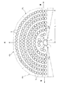
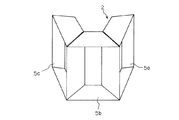
図1〜図4は本発明の太陽熱発電装置の一実施形態を示すもので、図1は全体構成図、図2はヘリオスタットと集光タワーおよびレシーバーの配置を平面的に示す説明図、図3はレシーバーの斜視図、図4はレシーバーを構成する1つの受光部の水平断面図である。
この太陽熱発電装置の基本的な構成は公知の装置と同様であり、上部にレシーバー2を備えた集光タワー1と、その周囲に設置される複数(多数)のヘリオスタット3を備え、太陽光線をヘリオスタット3で反射してレシーバー2に集光し、このレシーバー2では集光された太陽光線の熱で液体(通常、水)を加熱して蒸気を生成させ、この蒸気で蒸気タービン6を駆動して発電機7により発電を行うものである。すなわち、レシーバー2では系内を循環する流体を加熱して蒸気とし、この蒸気を蒸気タービン6に送ってタービンを駆動させ、発電機7で発電がなされる。蒸気タービン6を出た蒸気は、凝縮器9で冷却されて凝縮して液体になり、図示しない循環ポンプによりレシーバー2に循環する。
1 to 4 show an embodiment of a solar thermal power generation apparatus according to the present invention. FIG. 1 is an overall configuration diagram, and FIG. 2 is an explanatory diagram showing a plan view of the arrangement of a heliostat, a light collecting tower, and a receiver. 3 is a perspective view of the receiver, and FIG. 4 is a horizontal cross-sectional view of one light receiving portion constituting the receiver.
The basic configuration of this solar thermal power generation device is the same as that of a known device, which includes a condensing tower 1 having a
前記集光タワー1の高さは、通常、50〜150m程度であり、レシーバー2はその最上部に設置される。
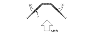
前記レシーバー2は、内部に流体が通される伝熱管20(通常、複数の並列した伝熱管)で構成される3つの受光部5a、5bおよび5cを有し、ヘリオスタット3で反射した太陽光線は、これら受光部5a〜5cに集光され、伝熱管20内を流れる流体を加熱する。伝熱管20で構成される受光部5a〜5cは、その前面側(受光面側)が凹形に窪んだ形状をしている。
前記ヘリオスタット3は、一般に、反射鏡30と、この反射鏡30の支持体31(支柱など)と、反射鏡30の角度を太陽の位置変化に追従して調整する駆動装置(図示せず)などで構成される。
The height of the condensing tower 1 is usually about 50 to 150 m, and the
The
The
前記ヘリオスタット3は、集光タワー1の周囲の広い領域(例えば、図2のL=50〜1000m程度)に多数設置されるが、集光タワー1を中心とした周方向で「北側を含む東側〜西側間」の領域に設置されることが好ましい。さきに述べたように、一般的に、北半球において緯度が大きい場合、集光タワーの南側に配置したヘリオスタットでは角度θの値が一日中大きいのに対して、北側に配置したヘリオスタットでは角度θの値の変化が比較的小さく、また角度θそのものも南側よりは相対的に小さいからである。また、東西に配置したヘリオスタットでは角度θの値が午前・午後で大きく変化するが、後述するように角度θの値は午前・午後でほぼ正反対の関係になり、本発明によれば、これをうまく利用して受光効率を安定化させることができる。
A large number of
ここで、集光タワー1を中心とした周方向で「北側を含む東側〜西側間」の領域とは、厳密に真東〜真西間の領域でなくてもよく、例えば、「東側」については真東を中心として方位角30〜60°程度の範囲(図2にαで示した方位角範囲)内の方位を、また、「西側」についても真西を中心として方位角30〜60°程度の範囲(図2にαで示した方位角範囲)内の方位を、それぞれ設置領域端とすればよい。したがって、本発明において「北側を含む東側〜西側間」とは、そのような意味を有するものとする。
Here, the region “between the east side and the west side including the north side” in the circumferential direction centering on the light collecting tower 1 may not be strictly the region between the east side and the west side. Indicates an azimuth within a range of about 30 to 60 ° azimuth centered on true east (azimuth angle range indicated by α in FIG. 2), and
上記のように設置された多数のヘリオスタット3は、集光タワー1を中心とした周方向で端から順に、ヘリオスタット群4a、ヘリオスタット群4bおよびヘリオスタット群4cに区分けされ(図2において破線で区分けしてあるのがヘリオスタット群4a〜4c)、各群のヘリオスタットにより、レシーバー2の異なる受光部に集光させられるようにしてある。本実施形態では、略東〜北東部の領域にあるものをヘリオスタット群4a、略北東〜北〜北西の領域にあるものをヘリオスタット群4b、略北西〜西の領域にあるものをヘリオスタット群4cとしている。これらヘリオスタット群4a〜4cの区分けは、発生させる蒸気の過熱度により配分が変わり、過熱度が大きいほどヘリオスタッド群4cの比率を大きくする。
A number of
前記レシーバー2の3つの受光部5a〜5cのうち、受光部5aが略東北東方向に向けられ、受光部5bが略北方向に向けられ、受光部5cが略西北西方向に向けられており、ヘリオスタット群4aにより受光部5aに集光し、ヘリオスタット群4bにより受光部5bに集光し、ヘリオスタット群4cにより受光部5cに集光するようにしてある。
ここで、受光部5aが向けられる方向は、東北東方向を中心として方位角30〜60°程度の範囲内の方位であることが、また、受光部5bが向けられる方向は、真北方向を中心として方位角30〜60°程度の範囲内の方位であることが、また、受光部5cが向けられる方向は、西北西方向を中心として方位角30〜60°程度の範囲内の方位であることが、それぞれ好ましい。
Of the three
Here, the direction in which the
本実施形態のようなヘリオスタットの配置(図2)を前提に、神奈川県横浜市鶴見区の緯度における夏至のcos(θ)の値を計算したものを図6に示す。これによれば、ヘリオスタット群4bの領域ではcos(θ)の値の変化が比較的小さい。一方、ヘリオスタット群4aとヘリオスタット群4cの領域では、cos(θ)の値が午前・午後で大きく変化するが、cos(θ)の値は午前・午後でほぼ正反対の関係になる。
FIG. 6 shows the calculated value of cos (θ) of the summer solstice at the latitude of Tsurumi-ku, Yokohama, Kanagawa, on the premise of the arrangement of the heliostat as in this embodiment (FIG. 2). According to this, the change in the value of cos (θ) is relatively small in the region of the
そこで、本発明の装置では、ヘリオスタット群4aとヘリオスタット群4cが集光を行う受光部5aと受光部5cを、液体を加熱して飽和蒸気とするための伝熱管で構成し、ヘリオスタット群4bが集光を行う受光部5bを、前記飽和蒸気をさらに加熱して過熱蒸気とするための伝熱管で構成するものである。このようにすることにより、液体を加熱して飽和蒸気にする段階では、cos(θ)の値が午前・午後で正反対の関係になるヘリオスタット群4a・受光部5aとヘリオスタット群4c・受光部5cが補完関係になるため、全体として高効率で安定した受光が可能となり、一方、飽和蒸気をさらに加熱して過熱蒸気とする段階では、cos(θ)の値の変化が比較的小さいヘリオスタット群4bと受光部5bで、高効率で安定した受光が可能となる。なお、上記とは逆に、受光部5bを飽和蒸気を得るための伝熱管で構成し、受光部5a,5cを過熱蒸気を得るための伝熱管で構成するような構造としないのは、受光部5a,5cでは、過熱蒸気を安定的に生成できないおそれがあるからである。
Therefore, in the apparatus of the present invention, the
したがって、本発明の装置では、系内を循環する発電用流体(例えば、水・水蒸気)の流路xの途中に、レシーバー2の受光部5aと受光部5cを直列または並列に設け、その下流側にレシーバー2の受光部5bを設けるものであり、これにより、液体が受光部5aと受光部5cで加熱されることで飽和蒸気となり、次いで、この飽和蒸気は、受光部5bで加熱されることで過熱蒸気となり、この過熱蒸気が蒸気タービン6に送られる。
この場合、流路xの途中に、並列した2つの流路部x1,x2を設けるとともに、流路部x1に受光部5aを、流路部x2に受光部5cをそれぞれ設け、その下流側の流路xに受光部5bを設け、さらに、受光部5aと受光部5cの流体入側の流路部x1,x2にはそれぞれ流量調整弁を設け、この流量調整弁により、受光部5aと受光部5cでの受熱量に応じてそれぞれの伝熱管に供給する流体量を調整できるようにすることが好ましい。また、蒸気タービン6を出た蒸気を凝縮するための凝縮器8の下流側の流路xにも流量調整弁を設けることが好ましい。
Therefore, in the apparatus of the present invention, the
In this case, two flow passage portions x1 and x2 arranged in parallel are provided in the middle of the flow passage x, the
図5は、そのような構成を有する本発明装置の一実施形態を示すもので、系内を循環する発電用流体のフロー図である。発電用流体(例えば、水・水蒸気)は、図中矢印方向に流れる。
系内を循環する発電用流体の流路xの途中には、並列した2つの流路部x1,x2が設けられるとともに、この2つの流路部x1,x2に受光部5aと受光部5cが設けられ、その下流側の流路xに受光部5bが設けられている。そして、受光部5aと受光部5cの流体入側の流路部x1,x2には、流量調整弁9,10が設けられている。また、受光部5aと受光部5cの流体出側の流路部x1,x2には温度計11,12が、受光部5bの流体入側の流路xには温度計13と圧力計14が、同じく流体出側の流路xには温度計15と圧力計16がそれぞれ設置されている。また、凝縮器8の流体出側の流路xには流量調整弁17が設けられている。
FIG. 5 shows an embodiment of the device of the present invention having such a configuration, and is a flow diagram of a power generation fluid circulating in the system. The power generation fluid (for example, water / steam) flows in the direction of the arrow in the figure.
In the middle of the flow path x of the power generation fluid circulating in the system, two flow path sections x1 and x2 are provided in parallel, and the
このような装置では、レシーバー2が稼動中は、流路部x1,x2の温度計11,12で測定された流体の温度、つまり受光部5aの流体出側の流路部x1を流れる流体の温度と受光部5cの流体出側の流路部x2を流れる流体の温度がほぼ等しくなるように、受光部5aと受光部5cの流体入側に設けられた流量調節弁9,10の開度を制御して流量調整を行う。すなわち、図6に示すように、受光部5aと受光部5cはコサイン効果の時間変化が大きく異なるので、それぞれの受光部での受熱量の差を補正するため、このような制御を行う。受光部5a、受光部5cを出て合流した流体は受光部5bに導かれるが、その途中で、飽和蒸気条件にあることを確認するために、温度計13と圧力計14により温度と圧力が計測される。また、受光部5bの流体出側では、蒸気の過熱度を確認するため、温度計15と圧力計16より流体の圧力と温度が計測される。上記のように測定・計算される蒸気の温度、圧力、過熱度が目標値と異なる場合には、凝縮器8の下流側の流路xに設けられた流量調整弁17で流量を増減し、蒸気の温度、圧力、過熱度が目標値と一致するように制御する。受光部5bを出た過熱蒸気は、蒸気タービン6を駆動し、発電機7による発電が行われる。蒸気タービン6を出た蒸気は凝縮器8で冷却され凝縮して液体となる。流体は、流量調整弁17で流量調整されながらポンプ18にて流路xを循環する。
図5の実施形態の装置において、以上のような運転を行うことにより、より効率的で且つ安定した発電を行うことができる。
In such an apparatus, while the
In the apparatus of the embodiment of FIG. 5, more efficient and stable power generation can be performed by performing the above operation.
1 集光タワー
2 レシーバー
3 ヘリオスタット
4a,4b,4c ヘリオスタット群
5a,5b,5c 受光部
6 蒸気タービン
7 発電機
8 凝縮器
9,10 流量調整弁
11,12,13,15 温度計
14,16 圧力計
17 流量調整弁
20 伝熱管
30 反射鏡
31 支持体
x 流路
x1,x2 流路部
DESCRIPTION OF SYMBOLS 1
Claims (7)
複数のヘリオスタット(3)を、集光タワー(1)を中心とした周方向で端から順に、ヘリオスタット群(4a)、ヘリオスタット群(4b)及びヘリオスタット群(4c)に区分けするとともに、レシーバー(2)の受光部を3つの受光部(5a)、(5b)及び(5c)で構成し、ヘリオスタット群(4a)により受光部(5a)に集光し、ヘリオスタット群(4b)により受光部(5b)に集光し、ヘリオスタット群(4c)により受光部(5c)に集光するようにし、
受光部(5a)と受光部(5c)を、液体を加熱して飽和蒸気とするための伝熱管で構成し、受光部(5b)を、前記飽和蒸気をさらに加熱して過熱蒸気とするための伝熱管で構成したことを特徴とする太陽熱発電装置。 Condensing tower (1) with receiver (2) at the top and a plurality of heliostats (3) installed around it, reflecting sunlight to heliostat (3) to receiver (2) The solar heat is collected and heated at the receiver (2) by heating the liquid with the heat of the concentrated solar rays to generate steam, and the steam turbine (6) is driven by the steam to generate power by the generator (7). In the power generator,
A plurality of heliostats (3) are divided into a heliostat group (4a), a heliostat group (4b), and a heliostat group (4c) in order from the end in the circumferential direction around the light collecting tower (1). The light receiver of the receiver (2) is composed of three light receivers (5a), (5b) and (5c), and is condensed on the light receiver (5a) by the heliostat group (4a), and the heliostat group (4b ) To the light receiving part (5b), and the heliostat group (4c) to collect the light to the light receiving part (5c).
The light-receiving part (5a) and the light-receiving part (5c) are composed of heat transfer tubes for heating the liquid to be saturated steam, and the light-receiving part (5b) is for further heating the saturated steam to be superheated steam. A solar thermal power generation device comprising a heat transfer tube.
受光部(5a)と受光部(5c)の出側の流路部(x1),(x2)を流れる流体の温度をそれぞれ測定し、両流体温度がほぼ等しくなるように、受光部(5a)と受光部(5c)の入側の流路部(x1),(x2)に設けられた流量調節弁で流量調整を行うことを特徴とする太陽熱発電装置の運転方法。 It is a driving | running method of the solar thermal power generation device of Claim 4, Comprising:
The temperature of the fluid flowing through the flow path portions (x1) and (x2) on the exit side of the light receiving portion (5a) and the light receiving portion (5c) is measured, and the light receiving portion (5a) is set so that both fluid temperatures are substantially equal. And a flow rate adjustment valve provided in the flow path portions (x1) and (x2) on the inlet side of the light receiving portion (5c), and a method of operating the solar thermal power generation apparatus.
受光部(5b)の入側の流路(x)を流れる蒸気の温度および圧力と、受光部(5b)の出側の流路(x)を流れる蒸気の温度および圧力を測定し、これら測定された蒸気の温度および圧力に応じて、凝縮器(8)の下流側の流路(x)に設けられた流量調整弁で流量調整を行うことを特徴とする太陽熱発電装置の運転方法。 It is a driving | running method of the solar thermal power generation device of Claim 5, Comprising:
Measure and measure the temperature and pressure of the steam flowing in the flow path (x) on the inlet side of the light receiving part (5b) and the temperature and pressure of the steam flowing in the flow path (x) on the outlet side of the light receiving part (5b). A method for operating a solar power generation apparatus, characterized in that the flow rate is adjusted by a flow rate adjustment valve provided in a flow path (x) downstream of the condenser (8) in accordance with the temperature and pressure of the steam that has been produced.
Priority Applications (1)
| Application Number | Priority Date | Filing Date | Title |
|---|---|---|---|
| JP2010266272A JP5598288B2 (en) | 2010-11-30 | 2010-11-30 | Solar thermal power generation apparatus and operation method thereof |
Applications Claiming Priority (1)
| Application Number | Priority Date | Filing Date | Title |
|---|---|---|---|
| JP2010266272A JP5598288B2 (en) | 2010-11-30 | 2010-11-30 | Solar thermal power generation apparatus and operation method thereof |
Publications (2)
| Publication Number | Publication Date |
|---|---|
| JP2012117411A true JP2012117411A (en) | 2012-06-21 |
| JP5598288B2 JP5598288B2 (en) | 2014-10-01 |
Family
ID=46500552
Family Applications (1)
| Application Number | Title | Priority Date | Filing Date |
|---|---|---|---|
| JP2010266272A Expired - Fee Related JP5598288B2 (en) | 2010-11-30 | 2010-11-30 | Solar thermal power generation apparatus and operation method thereof |
Country Status (1)
| Country | Link |
|---|---|
| JP (1) | JP5598288B2 (en) |
Cited By (5)
| Publication number | Priority date | Publication date | Assignee | Title |
|---|---|---|---|---|
| CN102967055A (en) * | 2012-11-09 | 2013-03-13 | 青海中控太阳能发电有限公司 | Heliostat field combined by small-area plane heliostat and large convergent heliostat |
| WO2014017171A1 (en) * | 2012-07-23 | 2014-01-30 | 住友重機械工業株式会社 | Solar light collecting system and solar thermal power generation system |
| WO2015129144A1 (en) * | 2014-02-28 | 2015-09-03 | 真 細川 | Solar thermal power generation-type desalinator |
| WO2018048617A1 (en) * | 2016-09-09 | 2018-03-15 | The Regents Of The University Of California | Selective absorber for harvesting solar energy |
| CN108375214A (en) * | 2016-10-28 | 2018-08-07 | 张建城 | Tower type solar suspended particles receiver and heliostat light-condensing array |
Families Citing this family (1)
| Publication number | Priority date | Publication date | Assignee | Title |
|---|---|---|---|---|
| CN110173903B (en) * | 2019-04-15 | 2020-09-29 | 中国联合工程有限公司 | Tower type solar thermal power generation system based on semicircular heat collector |
Citations (8)
| Publication number | Priority date | Publication date | Assignee | Title |
|---|---|---|---|---|
| US4289114A (en) * | 1978-09-12 | 1981-09-15 | The Babcock & Wilcox Company | Control system for a solar steam generator |
| JPS5989950A (en) * | 1982-10-14 | 1984-05-24 | ザ・バブコツク・アンド・ウイルコツクス・カンパニ− | Solar-ray receiver with dispersed panel |
| JPS6014053A (en) * | 1983-07-06 | 1985-01-24 | Mayekawa Mfg Co Ltd | Method for controlling heat pump utilizing solar heat |
| JPS6057155A (en) * | 1983-08-19 | 1985-04-02 | Syst Hoomuzu:Kk | Water heater unified solar and heat pump |
| WO2002025184A1 (en) * | 2000-09-19 | 2002-03-28 | Suria Holdings, Societe A Responsabilite Limitee | Method and device for producing steam by means of solar energy |
| US20080184789A1 (en) * | 2007-01-24 | 2008-08-07 | Deutsches Zentrum Fuer Luft- Und Raumfahrt E.V. | Method of operating a solar thermal process heat plant and solar thermal process heat plant |
| US20090101138A1 (en) * | 2007-10-22 | 2009-04-23 | Deutsches Zentrum Fuer Luft-Und Raumfahrt E.V. | Method of operating a solar thermal power plant and solar thermal power plant |
| US20090217921A1 (en) * | 2007-11-12 | 2009-09-03 | Luz Il Ltd. | Method and control system for operating a solar power tower system |
-
2010
- 2010-11-30 JP JP2010266272A patent/JP5598288B2/en not_active Expired - Fee Related
Patent Citations (8)
| Publication number | Priority date | Publication date | Assignee | Title |
|---|---|---|---|---|
| US4289114A (en) * | 1978-09-12 | 1981-09-15 | The Babcock & Wilcox Company | Control system for a solar steam generator |
| JPS5989950A (en) * | 1982-10-14 | 1984-05-24 | ザ・バブコツク・アンド・ウイルコツクス・カンパニ− | Solar-ray receiver with dispersed panel |
| JPS6014053A (en) * | 1983-07-06 | 1985-01-24 | Mayekawa Mfg Co Ltd | Method for controlling heat pump utilizing solar heat |
| JPS6057155A (en) * | 1983-08-19 | 1985-04-02 | Syst Hoomuzu:Kk | Water heater unified solar and heat pump |
| WO2002025184A1 (en) * | 2000-09-19 | 2002-03-28 | Suria Holdings, Societe A Responsabilite Limitee | Method and device for producing steam by means of solar energy |
| US20080184789A1 (en) * | 2007-01-24 | 2008-08-07 | Deutsches Zentrum Fuer Luft- Und Raumfahrt E.V. | Method of operating a solar thermal process heat plant and solar thermal process heat plant |
| US20090101138A1 (en) * | 2007-10-22 | 2009-04-23 | Deutsches Zentrum Fuer Luft-Und Raumfahrt E.V. | Method of operating a solar thermal power plant and solar thermal power plant |
| US20090217921A1 (en) * | 2007-11-12 | 2009-09-03 | Luz Il Ltd. | Method and control system for operating a solar power tower system |
Cited By (5)
| Publication number | Priority date | Publication date | Assignee | Title |
|---|---|---|---|---|
| WO2014017171A1 (en) * | 2012-07-23 | 2014-01-30 | 住友重機械工業株式会社 | Solar light collecting system and solar thermal power generation system |
| CN102967055A (en) * | 2012-11-09 | 2013-03-13 | 青海中控太阳能发电有限公司 | Heliostat field combined by small-area plane heliostat and large convergent heliostat |
| WO2015129144A1 (en) * | 2014-02-28 | 2015-09-03 | 真 細川 | Solar thermal power generation-type desalinator |
| WO2018048617A1 (en) * | 2016-09-09 | 2018-03-15 | The Regents Of The University Of California | Selective absorber for harvesting solar energy |
| CN108375214A (en) * | 2016-10-28 | 2018-08-07 | 张建城 | Tower type solar suspended particles receiver and heliostat light-condensing array |
Also Published As
| Publication number | Publication date |
|---|---|
| JP5598288B2 (en) | 2014-10-01 |
Similar Documents
| Publication | Publication Date | Title |
|---|---|---|
| JP5602306B2 (en) | Solar boiler and solar power plant using the same | |
| JP5598288B2 (en) | Solar thermal power generation apparatus and operation method thereof | |
| AU2009312347B2 (en) | Solar thermal power plant and dual-purpose pipe for use therewith | |
| US20120240577A1 (en) | Thermal generation systems | |
| KR101172578B1 (en) | Solar collector type of condensing solar light | |
| AU2013297546B2 (en) | Heat collection device for solar heat boiler, and tower-type solar heat boiler equipped with same | |
| JP6033405B2 (en) | Solar heat collection system | |
| US9228452B2 (en) | System and method for auxiliary fluid circuit heating or cooling of a superheater during startup and shutdown operations | |
| WO2019030560A2 (en) | Solar energy power generation system | |
| WO2014065158A1 (en) | Combined power generation plant | |
| JP6803846B2 (en) | Solar heat collection system and its operation method | |
| JP2012127577A (en) | Solar heat collection device and method of adjusting heat collection amount for the same | |
| JP2013096384A (en) | Solar thermal power generation method and facility | |
| AU2015297858A1 (en) | Solar heat collecting device | |
| WO2013005479A1 (en) | Solar light collection system and solar thermal electric power generation system | |
| Gardner et al. | Development of a solar thermal supercritical steam generator | |
| ES2345379B1 (en) | SOLAR PLANT COMBINED AIR AND STEAM TECHNOLOGY. | |
| Akhbari et al. | Design and Fabrication of a Parabolic Trough Collector and Experimental Investigation of Wind Impact on Direct Steam Production in Tehran | |
| CN103250011A (en) | Tower receiver configuration for high power values | |
| US20140238386A1 (en) | Radiation absorbing metal pipe | |
| Wattana et al. | Velocity and temperature distribution of flowing water in a solar parabolic trough receiver |
Legal Events
| Date | Code | Title | Description |
|---|---|---|---|
| A621 | Written request for application examination |
Free format text: JAPANESE INTERMEDIATE CODE: A621 Effective date: 20130306 |
|
| A131 | Notification of reasons for refusal |
Free format text: JAPANESE INTERMEDIATE CODE: A131 Effective date: 20140121 |
|
| A521 | Written amendment |
Free format text: JAPANESE INTERMEDIATE CODE: A523 Effective date: 20140320 |
|
| TRDD | Decision of grant or rejection written | ||
| A01 | Written decision to grant a patent or to grant a registration (utility model) |
Free format text: JAPANESE INTERMEDIATE CODE: A01 Effective date: 20140715 |
|
| A61 | First payment of annual fees (during grant procedure) |
Free format text: JAPANESE INTERMEDIATE CODE: A61 Effective date: 20140728 |
|
| R150 | Certificate of patent or registration of utility model |
Ref document number: 5598288 Country of ref document: JP Free format text: JAPANESE INTERMEDIATE CODE: R150 |
|
| LAPS | Cancellation because of no payment of annual fees |