JP2012106831A - Cord reel - Google Patents
Cord reel Download PDFInfo
- Publication number
- JP2012106831A JP2012106831A JP2010256606A JP2010256606A JP2012106831A JP 2012106831 A JP2012106831 A JP 2012106831A JP 2010256606 A JP2010256606 A JP 2010256606A JP 2010256606 A JP2010256606 A JP 2010256606A JP 2012106831 A JP2012106831 A JP 2012106831A
- Authority
- JP
- Japan
- Prior art keywords
- reel
- cord
- stopper
- casing
- wound
- Prior art date
- Legal status (The legal status is an assumption and is not a legal conclusion. Google has not performed a legal analysis and makes no representation as to the accuracy of the status listed.)
- Pending
Links
- 230000015572 biosynthetic process Effects 0.000 abstract description 2
- 230000002093 peripheral effect Effects 0.000 description 12
- 238000004804 winding Methods 0.000 description 10
- XEEYBQQBJWHFJM-UHFFFAOYSA-N Iron Chemical compound [Fe] XEEYBQQBJWHFJM-UHFFFAOYSA-N 0.000 description 2
- 230000007812 deficiency Effects 0.000 description 2
- 238000013459 approach Methods 0.000 description 1
- 238000010586 diagram Methods 0.000 description 1
- 230000000694 effects Effects 0.000 description 1
- 229910052742 iron Inorganic materials 0.000 description 1
- 230000009191 jumping Effects 0.000 description 1
- 230000004048 modification Effects 0.000 description 1
- 238000012986 modification Methods 0.000 description 1
- 239000011347 resin Substances 0.000 description 1
- 229920005989 resin Polymers 0.000 description 1
- 230000009466 transformation Effects 0.000 description 1
Images


Landscapes
- Storing, Repeated Paying-Out, And Re-Storing Of Elongated Articles (AREA)
Abstract
Description
本発明は、回転するリールにコードを収納して構成されるコードリールに関する。 The present invention relates to a cord reel configured by storing a cord in a rotating reel.
この種のコードリールとして、例えば特許文献1には、コードを収納するリールと、リールに回転トルクを与える付勢手段とを備え、コードの引出し時に付勢手段によってリールが回転するのを防止するために、リールの内周部分に係止するストッパーを設けたものが開示されている。
As this type of code reel, for example,
また別な特許文献2には、付勢手段の回転トルクに抗して、リールの回転を抑制する制動手段を設けたコードリールが開示されている。
Another
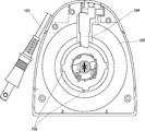
図8および図9は、従来のコードリールを示したものであり、ここで101はリール102に収納するコード、103は付勢手段としてのゼンマイ、104はストッパーであるが、上述のようにストッパー104は、リール102の内周部分に形成した凹状の係止部105に係止して、ゼンマイ103によるリール102の回転を防止している。
8 and 9 show a conventional cord reel, where 101 is a cord stored in the
しかし、リール102の内周部分はスペースが少なく、係止部105を多く形成できないため、一回転当り1〜4箇所しかリール102に係止部105を設けることができない。そのため、コード101を引き出して固定した時に、コード101の長さを細かく設定できず、使い勝手の悪いコードリールを使用せざるを得なかった。
However, since the inner peripheral portion of the
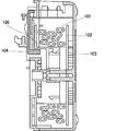
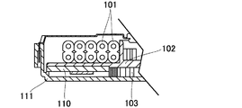
また図10および図11は、別な従来のコードリールを示したものである。同図において、110はリール102に装着される制動手段としてのブレーキ部品であり、これはコード101をリール102に収納する際に、リール102の回転に伴い発生する遠心力で、ブレーキ部品110をケース111の側面に押し当てて、コード101の戻り速度を抑制し、コード101の収納時におけるプラグ112の飛び跳ねを抑えるものである。
10 and 11 show another conventional cord reel. In the figure,
しかし、ブレーキ部品110を単独で設ける必要がある上に、リール102の全回転域にブレーキをかけながら、コード101をリール102に収納させなければならず、回転トルクの強いゼンマイ103が必要になる。つまり、従来はコード101の戻り速度を抑制するために、ブレーキ部品110を削減して構造を簡単にすることができなかった。
However, it is necessary to provide the
そこで本発明は、難しい機構を採用することなく、コードの引き出し長さを細かく設定することが可能なコードリールを提供することを第1の目的とする。 Accordingly, a first object of the present invention is to provide a cord reel capable of finely setting a cord drawing length without employing a difficult mechanism.
また本発明は、難しい機構を採用することなく、コードの戻り速度を抑制することが可能なコードリールを提供することを第2の目的とする。 A second object of the present invention is to provide a cord reel capable of suppressing the return speed of the cord without employing a difficult mechanism.
請求項1の発明では、リールの外周にストッパーとの係止部を設けることにより、係止部を形成するスペースを大きく確保して、従来よりも多数の係止部を設けることができる。このため、難しい機構を採用することなく、リールからのコードの引き出し長を細かく設定でき、コードを必要な長さに過不足なく引き出すことが可能になり、非常に使い勝手の良いコードリールを提供できる。 According to the first aspect of the present invention, by providing a locking portion with the stopper on the outer periphery of the reel, a large space for forming the locking portion can be secured and a larger number of locking portions can be provided than before. For this reason, it is possible to finely set the length of the cord to be drawn from the reel without adopting a difficult mechanism, and it is possible to draw the cord to the required length without excess or deficiency, thereby providing a very convenient cord reel. .
請求項2の発明では、単独のブレーキ部品を削減して、このブレーキ部品を無くすことにより、リールの全回転域に作用したブレーキ部品の負荷を、プラグがケーシングに当たる直前付近にだけ、ケーシングに設けた凸部と、リールに収納する時のコードの乱巻き部との接触する負荷に低減できる。そのため、従来よりも付勢力の弱い付勢手段の使用が可能となり、難しい機構を採用することなく、コードの戻り速度を抑制する安価なコードリールを提供できる。
In the invention of
請求項1の発明によれば、難しい機構を採用することなく、コードの引き出し長さを細かく設定することが可能なコードリールを提供できる。 According to the first aspect of the present invention, it is possible to provide a cord reel capable of finely setting the cord drawing length without employing a difficult mechanism.
請求項2の発明によれば、コードの戻り速度を抑制することが可能なコードリールを提供できる。
According to the invention of
以下、添付図面を参照しながら、本発明におけるコードリールの好ましい実施例を説明する。なお、それぞれの実施例について共通する構成には共通する符号を付し、共通する箇所については重複を極力避けて説明する。 Hereinafter, preferred embodiments of a cord reel according to the present invention will be described with reference to the accompanying drawings. In addition, the same code | symbol is attached | subjected to the common structure about each Example, and duplication is demonstrated about a common location as much as possible.
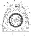
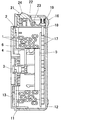
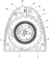
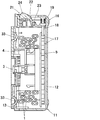
図1および図2は、本発明の第1実施例を示すコードリールの各図である。これらの各図において、1は必要な長さを有する可撓性のコード、2はそのコード1を巻取り収納する回動自在なリールであり、リール2は回転軸3を中心に有する筒状の巻取部4と、巻取部4の両端よりそれぞれ回転軸3の外周方向に拡がる円板状のフランジ5,6とにより構成される。本実施例に示すコードリールは、例えばアイロンなどの各種電気機器に装着され、前記コード1はその電気機器への給電を可能にする電源線として設けられている。また、コード1の先端には、商用電源のコンセントに差し込み可能なプラグ(図示せず)が配設される。
1 and 2 are diagrams of a cord reel showing a first embodiment of the present invention. In each of these drawings, 1 is a flexible cord having a necessary length, 2 is a rotatable reel that winds and stores the
11はコードリールの外郭をなす箱状のケーシングで、このケーシング11は、何れも樹脂製のケース12とカバー13を組み合わせて構成され、内部に前記リール2が回動自在に収容される。また14は、リール2とケーシング11との間に取付けられ、コード1を巻き取る方向にリール2への回転トルクを発生させる付勢手段としてのゼンマイである。ここでのゼンマイ14は、フランジ5の外側面に装着されるが、それ以外の位置に設けても構わない。前記コード1の先端にあるプラグは、コード1がリール2に全て巻き取られた状態でも、ケーシング11の外部に露出している。
16は、前記ゼンマイ14の付勢力によるリール2の回転を防止するロック機構である。ロック機構16は、前記リール2の軸方向一側をなすフランジ5の外周端に沿うように、所定の間隔で形成した複数の凹部17と、この凹部17に係合する凸状のストッパー18と、ストッパー18を常時凹部17に係合する方向に付勢する弾性体としてのばね19とを備えて構成される。本実施例では、被係合部たる凹部17がリール2の内周部分である巻取部4にではなく、リール2の外周部分であるフランジ5に設けられる点が注目され、それにより従来よりも多くの18個の凹部17がリール2に形成される。なお凹部17は、フランジ5の軸方向外面にではなく、別なフランジ6の軸方向外面に設けてもよい。
21は、凹部17とストッパー18との係合を解除するロック解除機構である。ロック解除機構21は、軸22を中心に回動し、その一端が前記ストッパー18の基端部に当接するレバー23と、レバー23の他端に設けられ、ケーシング11を貫通して外方に露出する解除ボタン24とにより構成される。これにより、ばね19の付勢に抗して解除ボタン24を押し込むと、軸22を支点としてストッパー18を持ち上げる方向にレバー23が回動し、ストッパー18と凹部17との係合が解除されて、ゼンマイ14の付勢力だけがリール2に作用するようになっている。
上記構成においてその作用を説明すると、コードリールの使用開始時には、ケーシング11の外部に露出したプラグを摘んで、コード1をリール2から引き出す。このとき、コード1を引き出す力がゼンマイ14およびばね19の付勢力を上回ると、ストッパー18がそれぞれの凹部17を乗り越えて、リール2が半時計方向に回転する。
The operation of the above configuration will be described. At the start of use of the cord reel, the
その後、コード1を必要な長さに引き出した状態で、当該コード1の引き出し力を弱くすると、今度はゼンマイ14によってリール2を時計方向に回転させようとする力が作用する。このゼンマイ14からリール2に与えられる回転トルクは、コード2の引き出し長さが増大すると次第に強くなるが、その強さの度合いに拘らず、ばね19により付勢されたストッパー18が凹部17に突き当たって、そこから抜け出せない状態になり、コード1を巻き取ろうとするリール2の回転が防止され、コード1は引き出された位置で固定される。このときのストッパー18は、リール2に設けられた凹部17の一つにどこでも係合できるために、コード1の引き出し長さを従来のものよりも細かく設定できる。そして、リール2から引き出されたコード1の先端にあるプラグをコンセントに差し込むことにより、コード1を経由して電気機器への給電を行なうことができる。
Thereafter, when the pulling force of the
一方、電気機器の使用が終了して、コンセントに差し込まれたプラグを外し、引き出されたコード1をケーシング11内に収納する場合は、ロック解除機構21の解除ボタン24を押動操作すると、ばね19の付勢に抗して、軸22を支点としてレバー23が回動し、ストッパー18が凹部17から離れて、リール2が回転可能な状態になる。それによりリール2は、ゼンマイ14から与えられる回転トルクによってコード1を巻き取る方向に回転し、コード1がケーシング11内に収納される。
On the other hand, when the use of the electric device is finished, the plug inserted into the outlet is removed, and the drawn
以上のように本実施例では、コード1を収納するリール2と、このリール2に対してコード1を収納する方向に回転トルクを与える付勢手段としてのゼンマイ14と、ゼンマイ14によるリール2の回転を防止する可動可能なストッパー18とから構成されるコードリールにおいて、リール2の外周にストッパー18との係止部である凹部17を設けている。
As described above, in this embodiment, the
この場合、リール1の外周にストッパー18との係止部である凹部17を設けることにより、凹部17を形成するスペースを大きく確保して、従来よりも多数の凹部17を設けることができる。このため、難しい機構を採用することなく、凹部17の形成位置を変えるだけで、リール2からのコード1の引き出し長を細かく設定でき、コード1を必要な長さに過不足なく引き出すことが可能になり、非常に使い勝手の良いコードリールを提供できる。
In this case, by providing the
なお本実施例において、凹部17は円板状をなすフランジ5の外周端に沿って、均等な間隔で形成するのが好ましい。そうすることで、凹部17の個数を効果的に増やし、またコード1の引き出し長を均等に細かく設定することが可能になる。また、凹部17をフランジ5の外周端よりも外周方向にはみ出して形成すると、ケーシング11ひいてはコードリールの大型化を招くので、凹部17の外端とフランジ5の外周端とを一致させることで、凹部17の個数を最大限に増やしつつ、ケーシング11の大型化を回避することができる。
In this embodiment, the
また、係止部としての凹部17は別な形状(例えば凸部)であってもよく、それに対応してストッパー18の形状を選定すればよい。
Moreover, the recessed
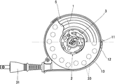
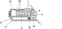
図3〜図7は、本発明の第2実施例を示すコードリールの各図である。図3〜図5に示すコードリールについて、ここではコード1を巻取り収納する回動自在なリール2が、回転軸3を中心に有する筒状の巻取部4と、巻取部4の一端すなわち下端より回転軸3の外周方向に拡がる円板状のフランジ5とにより構成され、コード1はケーシング11内において、フランジ5に接した状態で巻取部4に巻取り収納される。また31は、コード1の先端に配設されるプラグであり、これは第1実施例で説明したようにケーシング11の外部に常時露出して、商用電源のコンセント(図示せず)に着脱可能に差し込まれる。
3 to 7 are views of a cord reel showing a second embodiment of the present invention. 3 to 5, here, a
箱状のケーシング11は、コードリールの機構部全体(コード1,リール2,ゼンマイ14など)を収納するもので、これはケーシング11の底面と側面をなすケース12と、ケーシング11の上面をなし、ケース12の上部開口を塞ぐプレート状のカバー13とを嵌合して構成される。但し、ここでは前記図10や図11の従来例のように、単独のブレーキ部品110は存在せず、代わりにブレーキ部品110としての効果を得るために、リール2の回転を抑制する制動手段として、カバー13の内面に一体形成した複数の凸部33を有する。この凸部33は、リール2に巻き取られるコード1の放射方向中間部から外周部にかけて、当該コード1の表面に接するような形状で形成される。なおここでは、カバー13がリール2に巻き取られるコード1の表面に対向している関係で、凸部33をカバー13の内面に設けているが、ケース12がコード1の表面に対向していれば、凸部33をケース12の内面に設けるのが好ましい。
The box-shaped
その他、14はコード1を巻き取る方向にリール2への回転トルクを発生させる付勢手段としてのゼンマイである。なお、ここでは図示していないロック機構16やロック解除機構21を含めた構成について、後述する別な変形例で説明する。
In addition, 14 is a spring as an urging means for generating a rotational torque to the
本実施例では、図3に示すコード1をリール2に完全に収納した状態から、プラグ31を手で摘んで、コード1を有効長(全長)まで引き出すのに従い、ゼンマイ14の引き締めが増して、コード1を巻き取る方向へのリール2の回転力が大きくなる。リール2に対するゼンマイ14の付勢力が最大な状態で、前記ロック解除機構21を操作してコード1を収納させた場合、プラグ31が飛び跳ねたり、プラグ31の付け根がケーシング11に衝突および屈曲したりすることが繰り返されると、やがてコード1の断線に至るので、これを防ぐために、コード1がリール2に巻き取られて、プラグ31がケーシング11の当接部に近づく手前で、コード1の巻き取り速度を抑制(遅く)できるように、カバー13の内面に設けた複数の凸部33と、リール2に収納する時のコード1の乱巻き部とを接触させる。これにより、リール2に巻き取られるコード1が凸部33に接触する衝撃と摩擦で、コード1が収納されるリール2の回転速度を抑制し、その結果、コード1の戻り速度を遅くすることができる。
In this embodiment, from the state in which the
また従来は、リール2の全回転域にブレーキ部品110の負荷が作用するので、コード1を巻き取る途中でリール2の回転が停止しないように、リール2に対して十分な回転トルクを発生させるゼンマイ14が必要であった。しかし本実施例では、全長まで引き出されたコード1がリール2に巻き取られる最初からではなく、途中から複数の凸部33が接するように、これ等の凸部33を配置することで、従来よりも小さな回転トルクをリール2に与えるゼンマイ14であっても、コード1を巻き取る途中でリール2の回転が停止するようなことはなく、結果的にコードリールをコンパクトで安価なものにすることができる。
Further, conventionally, since the load of the
このように本実施例では、コード1を収納するリール2と、リール2に回転トルクを与える付勢手段としてのゼンマイ14と、リール2の回転を抑制する制動手段とから構成されるコードリールにおいて、リール2の回転時にコード1と干渉する凸部33を、リール2を収納するケーシング11に設けて、前記制動手段を構成している。
As described above, in this embodiment, in the cord reel constituted by the
この場合、従来例における単独のブレーキ部品110を削減して、当該ブレーキ部品110を無くすことにより、リール2の全回転域に作用したブレーキ部品の負荷を、プラグ31がケーシング11に当たる直前付近にだけ、ケーシング11に設けた凸部33と、リール2に収納する時のコード1の乱巻き部との接触する負荷に低減できる。そのため、従来よりも付勢力の弱いゼンマイ14の使用が可能となり、難しい機構を採用することなく、コード1の戻り速度を抑制する安価なコードリールを提供できる。
In this case, by reducing the
次に、第2実施例の変化例を図6および図7に基づき説明する。この変化例では、フランジ6が設けられていないことを除いて、前記第1実施例における構成がそのまま組み込まれている。また本実施例の特徴として、カバー13の内面には複数の凸部33が一体的に形成される。この凸部33は、リール2に巻き取られるコード1の乱巻き部に対向して、コード1の全長の半分以上がリール2に巻き取られると、コード1の表面に接するような形状に形成される。
Next, a modified example of the second embodiment will be described with reference to FIGS. In this variation, the configuration in the first embodiment is incorporated as it is, except that the
コード1の引き出しに関する動作は、第1実施例で説明したとおりであって、ここでもコード1を有効長(全長)まで引き出すのに従い、ゼンマイ14の引き締めが増して、コード1を巻き取る方向へのリール2の回転力が大きくなる。その後、コード1を引き出した状態で、解除ボタン24を押動操作すると、ストッパー18が凹部17から離れて、ゼンマイ14から与えられる回転トルクによって、リール2がコード1を巻き取る方向に回転するが、その途中からカバー13の内面に設けた複数の凸部33と、リール2に巻き取られたコード1の乱巻き部が接触するようになる。したがってこの変形例でも、リール2に巻き取られるコード1が凸部33に接触する衝撃と摩擦で、コード1が収納されるリール2の回転速度が抑制され、コード1の戻り速度を遅くすることができる。
The operation relating to the withdrawal of the
また、全長まで引き出されたコード1がリール2に巻き取られる最初からではなく、途中からコード1の乱巻き部と凸部33が接するように、当該凸部33を配置することで、従来よりも小さな回転トルクをリール2に与えるゼンマイ14であっても、コード1を巻き取る途中でリール2の回転が停止するようなことはなく、結果的にコードリールをコンパクトで安価なものにすることができる。
Further, by arranging the
なお、本発明は上記各実施例に限定されるものではなく、種々の変形実施が可能である。 In addition, this invention is not limited to said each Example, A various deformation | transformation implementation is possible.
1 コード
2 リール
14 ゼンマイ(付勢手段)
17 凹部(係止部)
18 ストッパー
33 凸部(制動手段)
1
17 Concave part (locking part)
18
Claims (2)
前記リールに回転トルクを与える付勢手段と、
前記リールの回転を防止するストッパーとから構成されるコードリールにおいて、
前記リールの外周に前記ストッパーとの係止部を設けたことを特徴とするコードリール。 A reel for storing the cord,
Biasing means for applying a rotational torque to the reel;
In a cord reel composed of a stopper that prevents the reel from rotating,
A cord reel characterized in that a locking portion with the stopper is provided on an outer periphery of the reel.
リールに回転トルクを与える付勢手段と、
前記リールの回転を抑制する制動手段とから構成されるコードリールにおいて、
前記制動手段は、前記リールの回転時に前記コードと干渉する凸部を、前記リールを収納するケーシングに設けてなることを特徴とするコードリール。
A reel for storing the cord,
An urging means for applying rotational torque to the reel;
In a cord reel composed of braking means for suppressing rotation of the reel,
The cord reel according to claim 1, wherein the braking means is provided with a convex portion that interferes with the cord when the reel rotates, in a casing that houses the reel.
Priority Applications (1)
| Application Number | Priority Date | Filing Date | Title |
|---|---|---|---|
| JP2010256606A JP2012106831A (en) | 2010-11-17 | 2010-11-17 | Cord reel |
Applications Claiming Priority (1)
| Application Number | Priority Date | Filing Date | Title |
|---|---|---|---|
| JP2010256606A JP2012106831A (en) | 2010-11-17 | 2010-11-17 | Cord reel |
Publications (1)
| Publication Number | Publication Date |
|---|---|
| JP2012106831A true JP2012106831A (en) | 2012-06-07 |
Family
ID=46492914
Family Applications (1)
| Application Number | Title | Priority Date | Filing Date |
|---|---|---|---|
| JP2010256606A Pending JP2012106831A (en) | 2010-11-17 | 2010-11-17 | Cord reel |
Country Status (1)
| Country | Link |
|---|---|
| JP (1) | JP2012106831A (en) |
Cited By (3)
| Publication number | Priority date | Publication date | Assignee | Title |
|---|---|---|---|---|
| JP2020152466A (en) * | 2019-03-18 | 2020-09-24 | モリテックスチール株式会社 | Braking structure for long reels |
| CN116620963A (en) * | 2023-03-10 | 2023-08-22 | 深圳酷骑童趣科技有限公司 | Line body retracting device and children's car |
| CN117585544A (en) * | 2023-12-26 | 2024-02-23 | 江西思行智能设备制造有限公司 | A reel setting method and reel |
Citations (6)
| Publication number | Priority date | Publication date | Assignee | Title |
|---|---|---|---|---|
| JPS6115274U (en) * | 1984-06-29 | 1986-01-29 | 大同特殊鋼株式会社 | Cord winding device |
| JPS6251579A (en) * | 1985-08-27 | 1987-03-06 | Matsushita Electric Works Ltd | Recoil type cord pullout device |
| JPH05115397A (en) * | 1991-10-29 | 1993-05-14 | Matsushita Electric Ind Co Ltd | Vacuum cleaner |
| JP2003071198A (en) * | 2001-08-31 | 2003-03-11 | Matsushita Electric Ind Co Ltd | Iron |
| JP2003319729A (en) * | 2002-05-01 | 2003-11-11 | Doggy Man H A Co Ltd | Pet reed |
| JP2011172496A (en) * | 2010-02-23 | 2011-09-08 | Shigeaki Iwasaki | Winding device |
-
2010
- 2010-11-17 JP JP2010256606A patent/JP2012106831A/en active Pending
Patent Citations (6)
| Publication number | Priority date | Publication date | Assignee | Title |
|---|---|---|---|---|
| JPS6115274U (en) * | 1984-06-29 | 1986-01-29 | 大同特殊鋼株式会社 | Cord winding device |
| JPS6251579A (en) * | 1985-08-27 | 1987-03-06 | Matsushita Electric Works Ltd | Recoil type cord pullout device |
| JPH05115397A (en) * | 1991-10-29 | 1993-05-14 | Matsushita Electric Ind Co Ltd | Vacuum cleaner |
| JP2003071198A (en) * | 2001-08-31 | 2003-03-11 | Matsushita Electric Ind Co Ltd | Iron |
| JP2003319729A (en) * | 2002-05-01 | 2003-11-11 | Doggy Man H A Co Ltd | Pet reed |
| JP2011172496A (en) * | 2010-02-23 | 2011-09-08 | Shigeaki Iwasaki | Winding device |
Cited By (5)
| Publication number | Priority date | Publication date | Assignee | Title |
|---|---|---|---|---|
| JP2020152466A (en) * | 2019-03-18 | 2020-09-24 | モリテックスチール株式会社 | Braking structure for long reels |
| JP7157690B2 (en) | 2019-03-18 | 2022-10-20 | モリテックスチール株式会社 | Braking structure for reels for long bodies |
| CN116620963A (en) * | 2023-03-10 | 2023-08-22 | 深圳酷骑童趣科技有限公司 | Line body retracting device and children's car |
| CN116620963B (en) * | 2023-03-10 | 2025-10-10 | 深圳酷骑智能自行车科技有限公司 | Line retracting device and children's car |
| CN117585544A (en) * | 2023-12-26 | 2024-02-23 | 江西思行智能设备制造有限公司 | A reel setting method and reel |
Similar Documents
| Publication | Publication Date | Title |
|---|---|---|
| US9960546B2 (en) | Coiling device and household appliance having the same | |
| US20110177750A1 (en) | Spinner for toy top | |
| US10159222B2 (en) | Lead storage apparatus | |
| CN104112958A (en) | Cable Storage Device For A Charging Cable Of An Electric Vehicle | |
| CN104577565B (en) | Automatic winder and electrical equipment | |
| JP2015115123A (en) | Charging connector and cover structure | |
| TWI821239B (en) | Spinning reel | |
| JP2012001164A (en) | Webbing take-up device | |
| JP2013075756A (en) | Cable storage equipment and cable set provided with the same | |
| JPS5988165A (en) | Safety belt wind-up apparatus | |
| US9976532B2 (en) | Recoil starter | |
| JP5394829B2 (en) | Transfer tool with mute reversal prevention mechanism | |
| KR20090023890A (en) | Cable coiling device | |
| KR101485039B1 (en) | Webbing take-up device | |
| WO2012056517A1 (en) | Storage structure of charging cable | |
| JP2011246071A (en) | Webbing winding device | |
| JP2006034195A (en) | Fishing reel | |
| CN103161635A (en) | Recoil starter mechanism | |
| KR200454050Y1 (en) | Classroom Wire Reel | |
| JP7580767B2 (en) | Recoil Starter | |
| JP2500212Y2 (en) | Cord winding device | |
| JP5908299B2 (en) | Spiral spring device | |
| KR101069466B1 (en) | Cord reel assembly | |
| JP2003042041A (en) | Energy storage starter device | |
| JP2533447B2 (en) | Ink bottle |
Legal Events
| Date | Code | Title | Description |
|---|---|---|---|
| A621 | Written request for application examination |
Free format text: JAPANESE INTERMEDIATE CODE: A621 Effective date: 20130619 |
|
| A131 | Notification of reasons for refusal |
Free format text: JAPANESE INTERMEDIATE CODE: A131 Effective date: 20140304 |
|
| A521 | Written amendment |
Free format text: JAPANESE INTERMEDIATE CODE: A523 Effective date: 20140422 |
|
| A131 | Notification of reasons for refusal |
Free format text: JAPANESE INTERMEDIATE CODE: A131 Effective date: 20140826 |
|
| A521 | Written amendment |
Free format text: JAPANESE INTERMEDIATE CODE: A523 Effective date: 20141009 |
|
| A02 | Decision of refusal |
Free format text: JAPANESE INTERMEDIATE CODE: A02 Effective date: 20141224 |