JP2012106080A - Cleaning device equipped with debris sensor - Google Patents
Cleaning device equipped with debris sensor Download PDFInfo
- Publication number
- JP2012106080A JP2012106080A JP2012047075A JP2012047075A JP2012106080A JP 2012106080 A JP2012106080 A JP 2012106080A JP 2012047075 A JP2012047075 A JP 2012047075A JP 2012047075 A JP2012047075 A JP 2012047075A JP 2012106080 A JP2012106080 A JP 2012106080A
- Authority
- JP
- Japan
- Prior art keywords
- debris
- sensor
- signal
- cleaning device
- autonomous
- Prior art date
- Legal status (The legal status is an assumption and is not a legal conclusion. Google has not performed a legal analysis and makes no representation as to the accuracy of the status listed.)
- Granted
Links
- 238000004140 cleaning Methods 0.000 title claims abstract description 107
- 230000033001 locomotion Effects 0.000 claims description 29
- 230000004044 response Effects 0.000 claims description 24
- 238000001514 detection method Methods 0.000 abstract description 27
- 230000009471 action Effects 0.000 abstract description 21
- 230000006399 behavior Effects 0.000 description 59
- 238000012545 processing Methods 0.000 description 16
- 230000008859 change Effects 0.000 description 15
- 238000000034 method Methods 0.000 description 10
- 230000000712 assembly Effects 0.000 description 9
- 238000000429 assembly Methods 0.000 description 9
- 238000010586 diagram Methods 0.000 description 9
- 230000006870 function Effects 0.000 description 9
- 230000003287 optical effect Effects 0.000 description 8
- 230000003542 behavioural effect Effects 0.000 description 6
- 229910001369 Brass Inorganic materials 0.000 description 5
- 239000010951 brass Substances 0.000 description 5
- 239000000428 dust Substances 0.000 description 5
- 239000002245 particle Substances 0.000 description 5
- 230000004913 activation Effects 0.000 description 4
- 230000005540 biological transmission Effects 0.000 description 4
- 230000008569 process Effects 0.000 description 4
- 230000005855 radiation Effects 0.000 description 4
- 230000035945 sensitivity Effects 0.000 description 4
- 230000002238 attenuated effect Effects 0.000 description 3
- 230000007423 decrease Effects 0.000 description 3
- 238000001914 filtration Methods 0.000 description 3
- 230000036039 immunity Effects 0.000 description 3
- 230000007246 mechanism Effects 0.000 description 3
- 230000007704 transition Effects 0.000 description 3
- 230000003321 amplification Effects 0.000 description 2
- 230000009286 beneficial effect Effects 0.000 description 2
- 230000008901 benefit Effects 0.000 description 2
- 239000002131 composite material Substances 0.000 description 2
- 239000004020 conductor Substances 0.000 description 2
- 238000013016 damping Methods 0.000 description 2
- 230000003247 decreasing effect Effects 0.000 description 2
- 238000013461 design Methods 0.000 description 2
- 230000000694 effects Effects 0.000 description 2
- 239000002184 metal Substances 0.000 description 2
- 229910052751 metal Inorganic materials 0.000 description 2
- 238000003199 nucleic acid amplification method Methods 0.000 description 2
- 238000003860 storage Methods 0.000 description 2
- 244000203593 Piper nigrum Species 0.000 description 1
- 235000008184 Piper nigrum Nutrition 0.000 description 1
- BQCADISMDOOEFD-UHFFFAOYSA-N Silver Chemical compound [Ag] BQCADISMDOOEFD-UHFFFAOYSA-N 0.000 description 1
- 230000005534 acoustic noise Effects 0.000 description 1
- 230000004888 barrier function Effects 0.000 description 1
- 235000013614 black pepper Nutrition 0.000 description 1
- 239000003990 capacitor Substances 0.000 description 1
- 238000004891 communication Methods 0.000 description 1
- 238000010276 construction Methods 0.000 description 1
- 230000008878 coupling Effects 0.000 description 1
- 238000010168 coupling process Methods 0.000 description 1
- 238000005859 coupling reaction Methods 0.000 description 1
- 230000000593 degrading effect Effects 0.000 description 1
- 230000008021 deposition Effects 0.000 description 1
- 238000006073 displacement reaction Methods 0.000 description 1
- 238000009826 distribution Methods 0.000 description 1
- 239000010419 fine particle Substances 0.000 description 1
- 230000007274 generation of a signal involved in cell-cell signaling Effects 0.000 description 1
- 230000003116 impacting effect Effects 0.000 description 1
- 238000009413 insulation Methods 0.000 description 1
- 238000002955 isolation Methods 0.000 description 1
- 230000004807 localization Effects 0.000 description 1
- 238000004519 manufacturing process Methods 0.000 description 1
- 239000000463 material Substances 0.000 description 1
- 230000004048 modification Effects 0.000 description 1
- 238000012986 modification Methods 0.000 description 1
- 230000002085 persistent effect Effects 0.000 description 1
- 230000009467 reduction Effects 0.000 description 1
- 238000005070 sampling Methods 0.000 description 1
- 229910052709 silver Inorganic materials 0.000 description 1
- 239000004332 silver Substances 0.000 description 1
- 239000007787 solid Substances 0.000 description 1
- 239000000758 substrate Substances 0.000 description 1
- 208000024891 symptom Diseases 0.000 description 1
Images


Abstract
Description
関連特許文献のクロスリファレンス
本特許出願は、下記の共通所有の米国特許出願または特許に関し、その内容がすべて記載されたごとく、参照によりその内容はここに取り込まれたものとする。
This patent application is related to the following commonly owned US patent applications or patents, the contents of which are hereby incorporated by reference as if fully set forth.
2001年1月24日出願の米国特許出願番号09/768,773号であり、現在は米国特許第6,594,844号、タイトル名「ロボット障害物検出システム(Robot Obstacle Detection System(Atty.Dkt.DP−4)」
2002年1月3日出願の米国暫定特許出願番号60/345,764号、タイトル名「自律型ロボット用清浄機構(Cleaning Mechanisms for Autonomous Robot)」
2002年1月24日出願の米国特許出願番号10/056,804号、タイトル名「ロボットの局在化および制限のための方法とシステム(Method and System for Robot Localization and Confinement(Atty Dkt.DP.DP−6)」
2002年6月12日出願の米国特許出願番号10/167,851号、タイトル名「自律型ロボットのためのマルチモードカバレッジ用の方法とシステム(Method and System for Multi−Mode(登録商標) Coverage for an Autonomous Robot(Atty Dkt.DP−5)」
2002年12月16日出願の米国特許出願番号10/320,729号、タイトル名「自律型床清掃ロボット(Autonomous Floor−Cleaning Robot(Atty Dkt.DP−10)」
2003年9月12日出願の米国特許出願番号10/661,835号、タイトル名「ロボット装置用のナビゲーション制御システム(Navigational Control System for Robotic Device(Atty Dkt.DP−9)」
発明の分野
本発明は、一般的に清浄装置に関し、特に、清浄装置の清浄経路においてデブリによる瞬間的衝突を感知するため、および清浄装置の動作モードの制御を可能にするためのデブリセンサに関する。「デブリ」という用語はここでは、自律型または非自律型であろうと、真空クリーナまたは他の清浄装置により収集される、ゴミ、埃、および/または他の微粒子または対象物を集合的に示すために使用される。
US patent application Ser. No. 09 / 768,773, filed Jan. 24, 2001, now US Pat. No. 6,594,844, entitled “Robot Obstacle Detection System (Atty. Dkt. . DP-4) "
US Provisional Patent Application No. 60 / 345,764, filed Jan. 3, 2002, titled “Cleaning Mechanisms for Autonomous Robots”
US patent application Ser. No. 10 / 056,804, filed Jan. 24, 2002, entitled “Method and System for Robot Localization and Confinement (Atty Dkt. DP. DP-6) "
US patent application Ser. No. 10 / 167,851, filed Jun. 12, 2002, entitled “Method and System for Multi-Mode® Coverage for Method and System for Autonomous Robots” an Autonomous Robot (Atty Dkt. DP-5) "
US patent application Ser. No. 10 / 320,729, filed Dec. 16, 2002, titled “Autonomous Floor-Cleaning Robot (Atty Dkt. DP-10)”
US patent application Ser. No. 10 / 661,835, filed Sep. 12, 2003, titled “Navigational Control System for Robotic Device (Atty Dkt. DP-9)”
The present invention relates generally to cleaning devices, and more particularly to a debris sensor for sensing instantaneous impacts due to debris in the cleaning path of the cleaning device and for enabling control of the operating mode of the cleaning device. The term “debris” is used herein to collectively indicate dirt, dust, and / or other particulates or objects collected by a vacuum cleaner or other cleaning device, whether autonomous or non-autonomous. Used for.
発明の背景
清浄装置用に適しているいくつかを含むデブリセンサは、この技術において知られている。デブリセンサは、上記に参照して特許出願において開示されるような、自律型清浄装置において有益であり、非自律型清浄装置においても有益であり、ユーザーに、特に汚れた領域に入りつつあるかどうかを示し、デブリの検出に応答してパワー設定を増加するか、または他のいくつかの動作設定を修正できるようにする。
BACKGROUND OF THE INVENTION Debris sensors, including some suitable for cleaning devices, are known in the art. The debris sensor is beneficial in autonomous and non-autonomous cleaning devices, such as disclosed in the above-referenced patent applications, and whether the user is entering a particularly dirty area. To increase the power setting in response to debris detection or to allow some other operational settings to be modified.
デブリセンサの例を下記に開示する。 Examples of debris sensors are disclosed below.
De Brey 3,674,316
De Brey 3,989,311
De Brey 4,175,892
Kurz 4,601,082
Westergren 4,733,430
Martin 4,733,431
Harkonen 4,829,626
Takashima 5,105,502
Takashima 5,136,750
Kawakami 5,163,202
Yang 5,319,827
Kim 5,440,216
Gordon 5,608,944
Imamura 5,815,884
Imamura 6,023,814
Kasper 6,446,302
Gordon 6,571,422
ここに開示された例のうち、多くのそのようなデブリセンサは、本質的には光学的であり、光エミッタおよび検出器を使用する。例えば、真空クリーナに使用される典型的な設計においては、光学センサの光送信機および光受信機は、埃が流れる吸引経路または清浄経路に露出されるように配置される。従って、真空クリーナの使用中は、埃粒子は、光が放射され、検出される光送信機および光受信機の露出された表面に付着し易く、光学センサの性能を劣化させる。
De Brey 3,674,316
De Brey 3,989,311
De Brey 4,175,892
Kurz 4,6011,082
Westergren 4,733,430
Martin 4,733,431
Harkonen 4,829,626
Takashima 5,105,502
Takashima 5,136,750
Kawakami 5,163,202
Yang 5,319,827
Kim 5,440,216
Gordon 5,608,944
Imamura 5,815,884
Imamura 6,023,814
Kasper 6,446,302
Gordon 6,571,422
Of the examples disclosed herein, many such debris sensors are optical in nature and use light emitters and detectors. For example, in a typical design used in a vacuum cleaner, the optical sensor's optical transmitter and optical receiver are positioned so that they are exposed to a suction or clean path through which dust flows. Thus, during use of the vacuum cleaner, dust particles tend to adhere to the exposed surfaces of the optical transmitter and optical receiver where light is emitted and detected, degrading the performance of the optical sensor.
従って、デブリの付着により劣化することのないデブリセンサを提供することが望まれている。 Therefore, it is desired to provide a debris sensor that does not deteriorate due to debris adhesion.
更に、従来技術に典型的なデブリセンサは、蓄積部または清浄経路に堆積したデブリのレベルには感度が良いが、瞬間的なデブリの衝突または遭遇に対しては特に感度が良いとはいえない。 In addition, debris sensors typical of the prior art are sensitive to the level of debris deposited in the accumulator or clean path, but are not particularly sensitive to instantaneous debris impacts or encounters.
従って、デブリの衝突を瞬間的に感知して応答でき、清浄対象の床または他の表面上のデブリに直ちに応答し、大気の流れの変動、瞬間的パワー、または清浄装置の他の動作状態に対する感度が減じられたデブリセンサを提供することが望ましい。 Thus, debris collisions can be sensed and responded instantaneously, responding immediately to debris on the floor or other surface to be cleaned, against atmospheric flow fluctuations, instantaneous power, or other operating conditions of the cleaning device It would be desirable to provide a debris sensor with reduced sensitivity.
また、例えば、デブリセンサにより生成された信号に基づいて、装置を「より汚れた」領域に向けて操縦するような、検出されたデブリに応答する動作モード、移動パターン、または行動を有する自律型清浄装置を提供することも有益である。 Also, an autonomous clean having an operating mode, movement pattern, or behavior in response to detected debris, for example, maneuvering the device towards a “dirty” area based on the signal generated by the debris sensor It is also beneficial to provide a device.
更に、自律型または非自律型清浄装置の何れかの動作モードを制御、選択、または変更するために使用できるデブリセンサを提供することは望ましい。 Furthermore, it would be desirable to provide a debris sensor that can be used to control, select or change the mode of operation of either an autonomous or non-autonomous cleaning device.
本発明は、デブリセンサと、そのようなデブリセンサを利用する装置を提供し、センサは、デブリの衝突に瞬間的に応答して、そのようなセンサを含む自律型または非自律型清浄装置の動作モードを制御、選択、または変更するために使用できる。 The present invention provides a debris sensor and a device that utilizes such a debris sensor, wherein the sensor responds instantaneously to a debris impact and the mode of operation of an autonomous or non-autonomous cleaning device that includes such a sensor. Can be used to control, select, or change.
本発明の1つの態様は、自律型清浄装置であって、清浄装置の移動を可能にするように動作可能な駆動システムと、駆動システムと通信状態にあるコントローラであって、駆動システムを制御して、清浄装置の少なくとも1つの移動パターンを提供するように動作可能なプロセッサを含むコントローラと、デブリを前記清浄装置の清浄経路へ向かって掃き上げるように動作可能なブラシアセンブリと、清浄装置がデブリに遭遇したことを示すデブリ信号を生成するデブリセンサとを備え、プロセッサは、デブリ信号に応答して、清浄装置の所定の動作モードから1つの動作モードを選択する。 One aspect of the present invention is an autonomous cleaning device, a drive system operable to allow movement of the cleaning device, and a controller in communication with the drive system, the control system controlling the drive system. A controller including a processor operable to provide at least one movement pattern of the cleaning device, a brush assembly operable to sweep debris toward a cleaning path of the cleaning device, and the cleaning device including the debris. And a debris sensor that generates a debris signal indicating that the device has encountered a response, wherein the processor selects one operating mode from a predetermined operating mode of the cleaning device in response to the debris signal.
動作モードの選択は、清浄装置の移動パターンを選択することを含むことができる。 The selection of the operating mode can include selecting a movement pattern of the cleaning device.
移動パターンは、デブリを含む領域のスポットカバレッジ、または、デブリを含む領域に向けて、清浄装置を操縦することを含むことができる。デブリセンサは、第1および第2デブリ信号を生成するようにそれぞれ動作可能な、等間隔に分離された第1および第2デブリ感知素子を含むことができ、プロセッサは、第1および第2デブリ信号のそれぞれに応答して、よりデブリの多い側(例えば、左または右側)に向けて操縦するような移動パターンを選択することができる。 The movement pattern can include maneuvering the cleaning device toward spot coverage of an area including debris or an area including debris. The debris sensor may include equally spaced first and second debris sensing elements operable to generate first and second debris signals, respectively, and the processor may include the first and second debris signals. In response, each of the movement patterns can be selected to steer towards the more debris side (eg, left or right).
デブリセンサは、清浄装置の清浄経路に近接して該ブラシアセンブリによって掃き上げられるデブリが衝突する場所に位置し、デブリに衝突したことに応答して、デブリに衝突したことを示す信号を生成する圧電センサ素子を含むことができる。 A debris sensor is located near the cleaning path of the cleaning device where the debris swept up by the brush assembly collides, and in response to hitting the debris, a piezoelectric that generates a signal indicating that it has hit the debris. Sensor elements can be included.
本発明のデブリセンサもまた非自律型清浄装置に取り込むことができる。本発明の本態様は、清浄経路に近接して位置し、デブリに衝突したことに応答して、デブリに衝突したことを示すデブリ信号を生成する圧電センサ素子と、デブリ信号に応答して、清浄装置の動作モードを変更するプロセッサを含むことができる。動作モードの変更は、ユーザーが認知できる表示灯を点灯すること、パワー設定を変更すること(例えば、より多くのデブリに遭遇したときはより高いパワー設定)、または、装置の移動速度を減じることを含むことができる。 The debris sensor of the present invention can also be incorporated into a non-autonomous cleaning device. This aspect of the present invention is located in proximity to the clean path and in response to impacting debris, a piezoelectric sensor element that generates a debris signal indicating that it has impacted debris, and in response to the debris signal, A processor may be included to change the operating mode of the cleaning device. Changing the operating mode can be done by turning on a user-recognizable indicator light, changing the power setting (for example, higher power setting when more debris is encountered), or reducing the movement speed of the device. Can be included.
本発明の更なる態様は、デブリセンサであり、清浄装置の清浄経路に近接してまたはその内部に位置し、デブリに衝突したことに応答して、デブリに衝突したことを示す第1信号を生成する圧電素子と、第1信号を処理して、清浄装置が遭遇しているデブリの特徴を示す第2信号を生成するように動作可能なプロセッサを含む。その特徴は、例えば、デブリの量または体積パラメータ、または清浄装置の現在の位置から、デブリを含む領域へのベクトルであってよい。 A further aspect of the present invention is a debris sensor, located near or within a cleaning path of a cleaning device, that generates a first signal indicating collision with debris in response to collision with debris. And a processor operable to process the first signal and generate a second signal indicative of the characteristics of the debris encountered by the cleaning device. The feature may be, for example, a vector from a debris amount or volume parameter, or a current location of the cleaning device to an area containing debris.
本発明の別の態様は、床または他の表面をカバーする自律型清浄装置の運動を利用して、清浄装置の移動についての知識と提携してデブリ信号を処理し、デブリ勾配を計算する。デブリ勾配は、自律型清浄装置が表面に沿って移動するときの、デブリ衝突計数の変化を示す。勾配の符号(デブリの増加または減少に関連して、正または負)を調べることにより、自律型清浄装置コントローラは、装置の経路または移動パターンを連続的に調整して、デブリ領域を効果的に清浄する。 Another aspect of the present invention utilizes the motion of an autonomous cleaning device that covers a floor or other surface to process the debris signal and calculate the debris gradient in conjunction with knowledge about the movement of the cleaning device. The debris gradient indicates the change in debris collision count as the autonomous cleaning device moves along the surface. By examining the sign of the slope (positive or negative in relation to increasing or decreasing debris), the autonomous cleaning device controller continuously adjusts the device path or movement pattern to effectively debris the region. Clean.
本発明のこれらのおよび他の態様、特徴、および利点は、本発明の実施形態が例として示され、記述される添付図を参照しての下記の記述からより明白になるであろう。 These and other aspects, features, and advantages of the present invention will become more apparent from the following description with reference to the accompanying drawings, in which embodiments of the invention are shown and described by way of illustration.
本発明、および付随する特徴および利点のより完全な理解は、添付図と携帯して考慮するに、本発明の下記の詳細な記述を参照することにより得られるであろう。
発明の詳細な説明
本発明のデブリセンサを、自律型清浄装置の広い範囲(そして実際は、図7に例として示した非自律型清浄装置にも)に組み込むことができるが、まず、図1〜図3に示す典型的な自律型清浄装置の流れで記述する。そのような自律型清浄装置の構造、機能、および行動モードの更なる詳細は、上記のクロスリファレンスの節で引用した特許出願に記述されており、それぞれは、参照によりここに組み込まれたものとする。従って、下記の詳細記述は、下記の節により構成される。
A more complete understanding of the present invention and the attendant features and advantages will be obtained by reference to the following detailed description of the invention, taken in conjunction with the accompanying drawings.
DETAILED DESCRIPTION OF THE INVENTION Although the debris sensor of the present invention can be incorporated into a wide range of autonomous cleaning devices (and in fact also in the non-autonomous cleaning device shown as an example in FIG. 7), first, FIG. This is described in the flow of a typical autonomous cleaning device shown in FIG. Further details of the structure, function and mode of action of such an autonomous cleaning device are described in the patent applications cited in the cross-reference section above, each of which is incorporated herein by reference. To do. Therefore, the following detailed description is composed of the following sections.
I. 典型的な自律型清浄装置
II. 自律型清浄装置の行動モード
III.デブリセンサ構造
IV.信号処理
V. 結論
I.自律型清浄装置
いくつかの図を通して、類似の参照番号は、対応するまたは同様な素子を特定している図を参照され、図1は、典型的な自律型清浄ロボット装置100の概略平面図であり、装置内には、本発明によるデブリセンサが組み込まれている。図2は、図1のロボット装置100のハードウェアのブロック図である。
I. Typical autonomous cleaning device
II. Autonomous Cleaner Behavior Mode
III. Debris sensor structure
IV. Signal processing Conclusion I. Autonomous Cleaning Device Throughout the several figures, like reference numerals are referenced to identify corresponding or similar elements, and FIG. 1 is a schematic plan view of a typical autonomous cleaning
iRobot Corporation of Burlington、MAにより、ROOMBAの登録商標で商用化されているロボット装置100の、ハードウェアと行動モード(清浄動作のためのカバレッジ行動または移動パターン;一時的な移動パターンへの退避行動;および緊急事態に対する安全行動)の例を、本発明のデブリ感知システムがどのように採用されるかについてのより完全な理解のために、下記に説明する。しかし、本発明はまた、非自律型清浄装置にも採用でき、その例を、図7に関連付けて下記に記述する。
Hardware and action mode (coverage action or movement pattern for clean operation; retreat action to temporary movement pattern;
下記の記述において、「前方」および「前」という用語は、ロボット装置の運動の主要方向(前方)を示すために使用される(図1において参照文字「FM」で示される矢印を参照)。ロボット装置100の前/後軸FAxは、主要側と非主要側とそれぞれが定義される、ほぼ対称な右半分と左半分にロボット装置100を分割する、ロボット装置100の中央径と一致する。
In the following description, the terms “forward” and “front” are used to indicate the main direction (forward) of movement of the robotic device (see the arrow indicated by the reference character “FM” in FIG. 1). The front / rear axis FA x of the
そのようなロボット装置100の例は、概略ディスク形状の格納構造を有しており、シャーシ102と、シャーシ102に固定された外部シェル104が含まれ、最小高さの構造的包絡線を画定している(家具の下における移動を容易にするために)。ロボット装置100を備えるハードウェアは一般的に、それぞれ、パワーシステム、起動パワーシステム(ここでは、「駆動システム」とも称せられる)、センサシステム、制御モジュール、サイドブラシアセンブリ、または自己調整清浄ヘッドシステムの基本素子として分類でき、その全部は、格納構造と組み合わせて統合されている。そのように分類されたハードウェアに加えて、ロボット装置100は更に、概略弧状構成および前輪アセンブリ108を有する前方バンパー106を含む。
An example of such a
前方バンパー106(単一構成要素して示されているか;または2部分からなる構成要素)は、シャーシ102と移動可能に統合されており(変位可能支持部材対により)、そこから外側に延伸している。ロボット装置100が、その移動中に障害物(例えば、壁、家具)に衝突するといつでも、バンパー106はシャーシ102に向けて変位(圧縮)され、障害物との接触が終了すると、元の延伸した(動作する)姿勢に戻る。
The front bumper 106 (shown as a single component; or a two-part component) is movably integrated with the chassis 102 (by a displaceable support member pair) and extends outwardly therefrom. ing. Whenever the
前輪アセンブリ108は、シャーシ102に、偏って組み合わせられて搭載されていて、それにより、前輪アセンブリ108は、清浄動作中は、引っ込んだ姿勢にあり(ロボット装置100の重量のため)、清浄中の表面上を自由に回転する。前輪アセンブリ108が、動作中に急斜面(例えば、下降階段、中二階の床)に遭遇すると、前輪アセンブリ108は、延伸した姿勢に傾けられる。
The
ロボット装置100の電気で作動するハードウェアに動力を与えるエネルギーを供給するパワーシステムのハードウェアは、シャーシ102と組み合わせて統合された再充電可能バッテリーパック110(および関連する導線)を備える。
The power system hardware that provides energy to power the electrically powered hardware of the
図1に示すように、起動パワーシステムは、ロボット装置100の移動中にロボット装置100を推進し、例えば、サイドブラシアセンブリおよび自己調整清浄ヘッドなどの清浄機構を作動する手段を提供する。起動パワーシステムは、左および右主要駆動輪アセンブリ112Lと112R、それらに関連する独立電動モーター114Lと114R、およびそれぞれがサイドブラシアセンブリと自己調整清浄ヘッドを作動するためである電動モーター116と118を備えている。
As shown in FIG. 1, the activation power system provides a means to propel the
電動モーター114Lと114Rは、主要駆動輪アセンブリ112Lと112Rにそれぞれ機械的に結合されており、行動モードの実行に対する応答として、または、下記に詳細に記述されるように、図1に示す左および右デブリセンサ125Lと125Rにより生成されるデブリ信号に応答して、制御モジュールにより生成される制御信号により独立して作動される。
電動モーター114Lと114Rの独立した動作により、主要駆動輪アセンブリ112Lと112Rは、(1)ロボット装置100を、直線上を前方または後方へ推進するために、同じ方向に同じ速度で回転させられ、(2)ロボット装置100の、多様な右および/または左回転パターン(鋭い回転から、浅い回転までの範囲で)を実現するために、差分的に回転させられ(1つの車輪アセンブリが回転されない状態を含む)、および(3)ロボット装置100をその場所で回転する、つまり、「10セント銀貨上の回転」のために、反対方向に同じ速度で回転させられて、ロボット装置100の移動機能の幅広いレパートリを提供する。
Due to the independent operation of the
図1に示すように、センサシステムは、ロボット装置100の行動モード動作を制御する信号を生成するように動作する多様な異なるセンサユニットを備える。上述のロボット装置100は、障害物検出ユニット120、絶壁検出ユニット122、車輪落下センサ124、障害物追尾ユニット126、仮想壁全方向性検出器128、失速センサユニット130、主車輪エンコーダユニット132、および本発明に従う、下記に詳細を記述する左および右デブリセンサ125Lおよび125Rを含む。
As shown in FIG. 1, the sensor system includes a variety of different sensor units that operate to generate signals that control the behavior mode operation of the
例示された実施形態において、障害物(「衝突」)検出ユニット120は、前方バンパー106の変位可能支持部材対と組み合わせて搭載されるIRブレークビームセンサであってよい。これらの障害物検出ユニット120は、前方バンパー106が圧縮されるようにロボット装置100が障害物に衝突したときはいつでも、1つまたは2つ以上の支持部材対間の相対変位を示す1つまたは2つ以上の信号を生成するように動作する。これらの信号は、ロボット装置100の前−後軸FAXに関して、傷害物と接触する近似点(および実行すべき行動モード)を決定するために、制御モジュールにより処理される。
In the illustrated embodiment, the obstacle (“collision”)
絶壁検出ユニット122は、前方バンパー106と組み合わせて搭載される。各絶壁検出ユニット122は、エミッタから下方に出射された放射が、検出器により横切られて検出されている表面から反射されるように焦点を確立するように構成され、動作するIRエミッタ/検出器対を備える。反射された放射が検出器により検出されない場合、つまり、急斜面に遭遇した場合は、絶壁検出ユニット122は制御モジュール(1つまたは2以上の行動モードを実行させる)に信号を送信する。
The
接触スイッチのような車輪落下センサ124は、主要駆動車輪アセンブリ112Lと112Rと、前輪アセンブリ108のそれぞれと組み合わせて統合され、車輪アセンブリの何れかが引き出された姿勢にあるときは、つまり、横切っている表面と接触していないときはいつでも、信号を生成するように動作する(このことにより、制御モジュールは、1つまたは2つ以上の行動モードを実行する)。
A
上述の実施形態での障害物追尾ユニット126は、ロボット装置100の「主要」側(図1の右側)に搭載されたIRエミッタ/検出器対である。エミッタ/検出器対は、構成において絶壁検出ユニット122と類似しているが、エミッタがロボット装置100の主要側から横方向に放射を出射できるように配置されている。ユニット126は、障害物から反射され、検出器により検出された放射の結果として、障害物が検出されたときはいつでも、制御モジュールへ信号を送信するように動作する。制御モジュールは、この信号に応答して、1つまたは2つ以上の行動モードを実行させる。
The
ロボット装置100の上述の実施形態と一緒に使用される仮想壁検出システムは、外部シェル104の頂上に搭載された全方向性検出器128と、軸方向に向けられた閉じ込めビームを送信するスタンドアロン型送信ユニット(図示せず)を備える。スタンドアロン型送信ユニットは、出射された閉じ込めビームが、画定された作業領域へのアクセス路を阻害し、それによりロボット装置100を、画定された作業領域(例えば、ロボット装置100を、清浄する特別な部屋内に閉じ込める入口)の動作に限定する。閉じ込めビームを検出すると、全方向性検出器128は、制御モジュールへ信号を送信する(これにより、1つまたは2つ以上の行動モードが実行されて、ロボット装置100を、スタンドアロン型送信ユニットにより生成された閉じ込めビームから離れるように移動させる)。
The virtual wall detection system used in conjunction with the above-described embodiment of the
失速センサユニット130は、各電動モーター114L、114R、116、および118と組み合わせて統合され、関連する電動モーターにおいて電流の変化が検出されると(これは対応する被駆動ハードウェアにおける故障状態を示す)、制御モジュールへ信号を送信するように動作する。制御モジュールは、そのような信号に応答して、1つまたは2つ以上の行動モードを実行するように動作する。
The
主車輪エンコーダユニット132(図2参照)は、各主駆動車輪アセンブリ112Lと112Rと組み合わせて統合され、対応する車輪の回転を検出し、それに対応して制御モジュールに信号を送信するように動作する(車輪の回転は、ロボット装置100が走行した距離を推定するのに使用できる)。
A main wheel encoder unit 132 (see FIG. 2) is integrated in combination with each main
制御モジュール ここで図2を参照して、制御モジュールは、ロボット装置100のセンサと、制御可能なハードウェアに接続されたI/Oポートを含むマイクロプロセッシングユニット135と、マイクロコントローラ(Motorola MC9512E128CPV16ビットコントローラのような)、およびROMとRAMメモリを備える。I/Oポートは、マイクロコントローラとセンサユニット(下記により詳細を記述する左および右デブリセンサ125を含む)と制御可能なハードウェアの間のインタフェースとして機能し、センサユニットにより生成された信号をマイクロコントローラに転送し、マイクロコントローラにより生成された制御(命令)信号を制御可能なハードウェアに転送して、特別な行動モードを実行させる。
Control Module Referring now to FIG. 2, the control module includes a sensor of the
マイクロコントローラは、センサ信号を処理し、そのような処理信号に基づいて特別な行動モードを実行し、ロボット装置100に対して実行された行動モードに基づいて、制御可能なハードウェアに対して制御(命令)信号を生成するための命令セットを実行するように動作する。ロボット装置100に対する清浄カバレッジおよび制御プログラムは、マイクロプロセッシングユニット135のROMに格納されており、そこには、行動モード、センサ処理アルゴリズム、制御信号生成アルゴリズム、およびロボット装置100の制御をどの行動モードまたは複数の行動モードに与えるかを決める優先化アルゴリズムが含まれている。マイクロプロセッシングユニット135のRAMは、ロボット装置100の活動状態を格納するために使用され、ロボット装置100が現在作動されている行動モード(複数の行動モード)のIDと、それに関連するハードウェアコマンドが含まれている。
The microcontroller processes the sensor signal, executes a special behavior mode based on such a processing signal, and controls the controllable hardware based on the behavior mode executed for the
再び図1を参照して、格納構造の周辺の外部の粒子を集めて、その粒子を自己調整清浄ヘッドシステムに向かわせるように構成され、動作するサイドブラシアセンブリ140が示されている。サイドブラシアセンブリ140により、ロボット装置100が「障害物追尾」行動モードで作動されているときに、底板に近接する表面を清浄する機能がロボット装置100に与えられる。図1に示すように、好ましくは、サイドブラシアセンブリ140はロボット装置100の主要側の前方四分円においてシャーシ102と組み合わせて搭載される。
Referring again to FIG. 1, there is shown a
既述のロボット装置100用の自己調整清浄ヘッドシステム145は、二段階ブラシアセンブリと真空アセンブリを備え、それぞれは、電動モーターにより独立してパワーが供給される(図1の参照番号118は、実際には、1つはブラシアセンブリ用の、もう1つは真空アセンブリ用の2つの独立電動モーターを特定している)。ロボット装置100の清浄機能は、清浄ヘッドシステム145の幅(図1における参照文字Wを参照)により共通して特徴付けられる。
The described self-adjusting
ここで図3を参照して、ロボット装置100の1つの実施形態においては、清浄ブラシアセンブリは、非対称な、反回転フラッパおよび主ブラシ要素92と94をそれぞれ備え、それらは真空アセンブリ入口84の前方に配置され、粒子性デブリ127を、除去用埃カートリッジ86に向けるように動作する。図3に示すように、ロボット装置100はまた、下記に詳細に記述するように、圧電センサ素子であってよい、左および右デブリセンサ素子125PSを含むことができる。圧電デブリセンサ素子125PSは、ロボット装置100の清浄経路に位置することができ、例えば、清浄ヘッドの屋根に搭載され、それにより、ブラシ素子により掃き集められ、および/または真空により引き寄せられた粒子127が衝突したときは、デブリセンサ素子125PSは、デブリが衝突したこと、そしてこのようにして、自律型清浄装置が動作している領域にデブリが存在することを示す電気パルスを生成する。
With reference now to FIG. 3, in one embodiment of the
より特別には、図3に示す配置において、センサ素子125PSは、主およびフラッパブラシ94と92がそれに沿って出会う軸AXに実質的に位置しており、それにより、粒子は最大力でデブリセンサ素子125PSに衝突する。 More specifically, in the arrangement shown in FIG. 3, the sensor element 125PS is substantially located on the axis AX along which the main and flapper brushes 94 and 92 meet so that the particles are at maximum force with the debris sensor element. Collide with 125PS.
図1に示すように、そして、下記により詳細に記述するように、ロボット清浄装置は、左および右側圧電デブリセンサを取り付けることができ、ロボット装置が「汚れた」領域の方向を向くような信号を送るために処理できる、分離した左および右側デブリ信号を生成する。 As shown in FIG. 1, and as will be described in more detail below, the robotic cleaning device can be fitted with left and right piezoelectric debris sensors that signal the robotic device to point in the “dirty” area. Generate separate left and right debris signals that can be processed for transmission.
信号処理と、圧電デブリセンサにより生成されたデブリ信号に基づく行動モードの選択と共に、圧電デブリセンサの動作は、清浄装置の行動モードの一般的な態様の簡単な既述に従って、下記で検討される。
II 行動モード
ロボット装置100は、画定された作業領域を効果的に清浄するために、種々の行動モードを採用することができ、ここにおいて行動モードは制御システムの層であり、平行に作動できる。マイクロプロセッシングユニット135は、優先化調停方式を実行して、センサシステムからの入力に基づいて、与えられたいかなるシナリオに対しても、1つまたは2つ以上の主要動作モードを特定して実行するように動作する。
Along with signal processing and selection of a behavior mode based on the debris signal generated by the piezoelectric debris sensor, the operation of the piezoelectric debris sensor is discussed below in accordance with a brief description of the general aspects of the behavior mode of the cleaning device.
II Behavioral Mode The
既述したロボット装置100の行動モードは、(1)カバレッジ行動モード、(2)退避行動モード、および(3)安全行動モードにより特徴付けられる。カバレッジ行動モードは、主にロボット装置100がその清浄動作を、効率よくかつ効果的な方法で行うことを可能にするように設計され、退避および安全行動モードは、センサシステムからの信号が、ロボット装置100の通常動作が、例えば、障害物に遭遇して阻害されたり、または例えば急斜面が検出されて阻害されたりしそうであることを示すときに実行される優先行動モードである。
The behavior mode of the
ロボット装置100の代表的かつ例としてのカバレッジ行動(清浄)モードには、(1)「スポットカバレッジ」パターン、(2)「障害物追尾(または、「エッジ清浄」)カバレッジ」パターン、および(3)「部屋カバレッジ」パターンが含まれる。「スポットカバレッジ」パターンは、ロボット装置100に、定義作業領域内の限られた領域、例えば、交通量の多い領域を清浄させる。好適な実施形態においては、「スポットカバレッジ」パターンは、らせん状アルゴリズムにより実行される(しかし、例えば、多角形のような、自己閉塞領域アルゴリズムの他のタイプも使用できる)。ロボット装置100に、外側に向いたらせん状(好適)の、または内側に向いたらせん状の移動をさせるらせん状アルゴリズムは、マイクロプロセッシングユニット135から、主車輪アセンブリ112Lと112Rへの制御信号により、その回転半径/複数の半径を、時間の関数として変化させて(それにより、ロボット装置100のらせん状移動パターンが増大/減少される)実行される。
Exemplary and exemplary coverage behavior (clean) modes of the
ロボット装置100は、所定のまたはランダムな時間だけ、所定のまたはランダムな距離(例えば、最大らせん距離)、および/または特別な事象が起こるまで、例えば、障害物検出ユニット120の1つまたは2つ以上が起動されるまで(まとめて、過渡期状態)、「スポットカバレッジ」パターンで作動される。いったん、過渡期状態が起きると、ロボット装置100は、異なる動作モード、例えば、「直線」行動モード(ロボット装置100の好適な実施形態においては、「直線」行動モードは低い優先順位であり、ロボットを約0.306m/sの前もって設定された速度で、近似的な直線上を推進させるデフォルト行動)または、「直線」行動モードと組み合わせられた「バウンド」行動モードのような、異なる行動モードを実行、またはそのモードに遷移する。
The
過渡期状態が、ロボット装置100が障害物に遭遇した結果である場合は、ロボット装置100は、異なる行動モードに遷移する代わりに、別の行動を起こすことができる。ロボット装置100は、らせん状アルゴリズムの制御により、一時的にある行動モードを実行して障害物を回避またはそこから退避して、動作を再開することができる(つまり、同じ方向にらせん移動を継続する)。または、ロボット装置100は、らせん状アルゴリズムの制御により、一時的にある行動モードを実行して障害物を回避しまたはそこから退避して、動作を再開することができる(しかし反対方向、つまり、反射らせん移動)。
If the transitional state is a result of the
「障害物追尾カバレッジ」パターンにより、ロボット装置100は、定義された作業領域の周囲、例えば、壁で仕切られた部屋、および/または、定義された作業領域内の障害物(例えば、家具)の周囲を清浄する。好適には、図1のロボット装置100は、障害物追尾ユニット126(図1参照)を利用して、障害物、例えば、壁、家具などに関してのその姿勢を連続して維持し、ロボット装置100の運動により、障害物の周囲近くまで移動し、同時にその周囲を清浄することができる。障害物追尾ユニット126の異なる実施形態を使用して、「障害物追尾」行動パターンを実行することができる。
Due to the “obstacle tracking coverage” pattern, the
第1実施形態において、障害物追尾ユニット126は、障害物の存在または存在しないことを検出するように作動される。別の実施形態においては、障害物追尾ユニット126は、障害物を検出して、その障害物とロボット装置100の間に所定の距離を維持するように作動される。第1実施形態においては、マイクロプロセッシングユニット135は、障害物追尾ユニット126からの信号に応答して、小さな時計回りまたは反時計回りの回転を実行して、障害物に対してのその姿勢を維持するように動作する。ロボット装置100は、ロボット装置100が障害物検出から、非検出に(反射から、非反射に)遷移するときは小さな時計回りを実行し、またはロボット装置100が、非検出から、検出に(非反射から反射に)遷移するときは、小さな反時計回りを実行する。同様な回転行動がロボット装置100により実行されて、障害物からの所定の距離が維持される。
In the first embodiment, the
ロボット装置100は、所定のまたはランダムな時間だけ、所定のまたはランダムな距離(例えば、最大または最小距離)、および/または特別な事象が起こるまで、例えば、障害物検出ユニット120の1つまたは2つ以上が所定の回数だけ起動されるまで(まとめて、過渡期状態)、「障害物追尾」行動モードで作動される。ある実施形態においては、マイクロプロセッシングユニット135は、ロボット装置100を障害物に対して整列させるために、最小角度の反時計回りの回転を実行する「障害物追尾」行動モードにおいて、障害物検出ユニット120が起動されると、ロボット装置に「整列」行動モードを実行させる。
The
「部屋カバレッジ」パターンは、壁、階段、障害物、または他の障壁(例えば、仮想壁ユニット)により仕切られる如何なる定義作業領域を清浄するために、ロボット装置100により使用することができる。「部屋カバレッジ」パターンの好適な実施形態は、「直線」行動モードと組み合わせた「ランダムバウンド」行動モードを含む。最初は、ロボット装置100は「直線」行動モード、つまり、直線アルゴリズム(同じ回転速度で、同じ方向で動作している主要駆動車輪アセンブリ112Lと112R)の制御のもとで、障害物に遭遇するまで走行する。1つまたは2つ以上の障害物検出ユニット120が起動されると、マイクロプロセッシングユニット135は、起動された障害物追尾ユニット(複数)126に基づいて、新しい方向の容認できる範囲を計算するように動作する。マイクロプロセッシングユニット135は、容認できる範囲内から新しい方向を選択し、時計回り、または反時計回りの回転を実行して、最小移動で新しい方向を達成する。ある実施形態においては、新しい回転方向は、前方移動が続き、ロボット装置100の清浄性能を増大する。新しい方向は、方向の容認できる方向範囲から、またはある統計的選択方式、例えば、ガウス分布に基づいてランダムに選択してもよい。「部屋カバレッジ」行動モードの他の実施形態においては、マイクロプロセッシングユニット135を、センサシステムからの入力なしに、ランダムにまたは所定の回数だけ方向を変更するようにプログラムすることができる。
The “room coverage” pattern can be used by the
ロボット装置100は、所定のまたはランダムな時間だけ、所定のまたはランダムな距離(例えば、最大または最小距離)、および/または特別な事象が起こるまで、例えば、障害物検出ユニット120が所定回数だけ起動されるまで(まとめて過渡期状態)、「部屋カバレッジ」モードで作動される。
The
例として、ロボット装置100は、4つの退避行動モード、つまり「回転」行動モード、「エッジ」行動モード、「車輪落下」行動モード、および「緩慢」行動モードを含むことができる。この技術に精通した者は、ロボット装置100により他の行動モードが利用できるということを認識されよう。これらの行動モードの1つまたは2つ以上が、例えば、サイドブラシアセンブリ140または二段階ブラシアセンブリの電動モーター116と118の1つにおいて、低または高失速閾値以上の電流の上昇、所定の時間だけの前方バンパー106の圧縮された姿勢、車輪落下の検出に応答して実行される。
As an example, the
「回転」行動モードにおいて、ロボット装置100は、ランダムな方向に、より高速(例えば、公称回転速度の2倍)で開始し、より低速(公称回転速度の半分)に減じるように、つまり、それぞれ小パニック回転および大パニック回転で、その場所で回転する。好ましくは、小パニック回転は45°から90°の範囲であり、大パニック回転は、好ましくは、90°から270°の範囲である。「回転」行動モードは、ロボット装置100が、部屋の障害物上で、例えば、カーペットの高所部分、傾斜のあるランプ台の上で動きが取れなくなることを、部屋の障害物の下で、例えば、ソファの下で動きが取れなくなること、または狭い領域に閉じ込められることを回避する。
In the “rotate” behavior mode, the
「エッジ」行動モードにおいては、傷害物検出ユニット120の何れもが起動することなく、所定の角度、例えば60°だけ回転するまで、またはロボット装置が、「エッジ」行動モードの開始から、所定の角度、例えば、170°だけ回転するまで、障害物のエッジを追尾する。「エッジ」行動モードにより、ロボット装置100は、狭い領域から退避するために、可能な限り最小の穴を通過することが可能になる。
In the “edge” behavior mode, none of the
「車輪落下」行動モードにおいては、マイクロプロセッシングユニット135は、主車輪駆動アセンブリ112Lと112Rの方向を一時的に反転して、その後、それを停止する。起動された車輪落下センサ124が所定時間内に活動を停止すると、マイクロプロセッシングユニット135は、車輪落下センサ124の起動の前に、実行されていた行動モードを再実行する。
In the “wheel drop” behavior mode, the
ある事象、例えば、車輪落下センサ124または絶壁検出ユニット122の起動に応答して、「緩慢」行動モードが、所定の距離だけ実行されてロボット装置100を減速し、その後、元の動作速度に徐々に戻す。
In response to an event, for example, the activation of the
センササブシステムにより安全状態が検出されると、例えば、対応する電動モーターを一時的にオフにするようなブラシまたは車輪の失速が連続して起きたり、車輪落下センサ124または絶壁検出ユニット122が、所定の時間だけ増大して起動されたりすると、ロボット装置100は、一般的にはオフ状態になる。更に、可聴アラームが生成される。
When a safe state is detected by the sensor subsystem, for example, a brush or wheel stall that causes the corresponding electric motor to temporarily turn off occurs continuously, or the
ロボット装置100に対する行動モードの上記の記述は、単にロボット装置100により実行され得る動作モードのタイプを表現したものにすぎない。この技術に精通した者は、上述の行動モードが、他の組合せおよび/または状況でも実行でき、他の行動モードおよび移動パターンもまた可能であることを認識できよう。
III デブリセンサの構造と動作
図1から図3に示すように、本発明によれば、自律型清浄装置(および、同様に、図7に例として示した非自律型清浄装置)は、デブリセンサを組み込むことにより改善できる。図1から図3に例示された実施形態において、デブリセンササブシステムは、清浄装置の清浄経路に近接して、またはその内部に位置する左および右圧電デブリセンサ素子125Lと125Rと、センサからのデブリ信号を処理し、マイクロプロセッシングユニット135または他のコントローラへ転送するための電子機器素子を備える。
The above description of the behavior modes for the
III Structure and Operation of Debris Sensor As shown in FIGS. 1 to 3, according to the present invention, the autonomous cleaning device (and similarly, the non-autonomous cleaning device shown as an example in FIG. 7) incorporates the debris sensor. Can be improved. In the embodiment illustrated in FIGS. 1-3, the debris sensor subsystem includes left and right piezoelectric
自律型ロボット清浄装置に採用されると、デブリセンサからのデブリ信号は、行動モードを選択し(スポット清浄モードになるように)、動作状態(速度、パワー、またはその他のような)を変更し、デブリの方向に操縦し(特に、等間隔に離された左および右デブリセンサが使用されて差分信号が生成される)、または他の行動を起こすように使用することができる。 When employed in an autonomous robotic cleaning device, the debris signal from the debris sensor selects the behavior mode (to be in spot cleaning mode), changes the operating state (such as speed, power, or others) It can be used to steer in the direction of debris (especially, equally spaced left and right debris sensors are used to generate differential signals) or to take other actions.
本発明に係るデブリセンサはまた、非自律型清浄装置に組み込むことができる。例えば、図7に示すような相対的に従来技術に属する真空掃除機700などの非自律型清浄装置に採用されると、装置の清浄または真空経路内に位置する圧電デブリセンサ704PSにより生成されたデブリ信号706を、制御マイクロプロセッサ708により真空掃除機702の本体に採用して、ユーザーが認識できる信号(表示灯710を点灯するなどして)を生成し、パワーシステム703からのパワーを増大し、または行動のある組合せ(「高パワー」電灯の点灯および同時にパワーを増大するような)を取ることができる。
The debris sensor according to the present invention can also be incorporated into a non-autonomous cleaning device. For example, when employed in a relatively non-autonomous cleaning device such as the
デブリセンササブシステムの動作のアルゴリズムの態様は、図8にまとめてある。そこに示されるように、本発明に係る方法は、デブリとの衝突を、そして、デブリの存在、量または体積、および方向を示す左および右デブリ信号を検出すること(802)、デブリ信号値に基づいて、動作モードまたは移動パターン(「スポットカバレッジ」のような)を選択すること(804)、差分左/右デブリ信号に基づいて移動方向を選択すること(例えば、よりデブリが多い側へ向けて操縦すること)(806)、デブリの存在または他の特徴を示すユーザーが認識できる信号を生成すること(例えば、ユーザーが認識可能なLEDを点灯すること)(808)、または動作状態、例えばパワーを変更または制御すること(810)を含むことができる。 The algorithm aspects of the operation of the debris sensor subsystem are summarized in FIG. As shown therein, the method according to the invention detects collisions with debris and left and right debris signals indicating the presence, quantity or volume and direction of debris (802), debris signal values. To select an operating mode or movement pattern (such as “spot coverage”) based on 804, to select a movement direction based on the differential left / right debris signal (eg, to the more debris side) (806), generating a user-recognizable signal indicating the presence of debris or other characteristics (eg, lighting a user-recognizable LED) (808), or operating state, For example, changing or controlling power (810) can be included.
本発明の更なる実践は、自律型清浄装置の、床または他の表面上の運動を利用して、清浄装置の移動についての情報と結び付けてデブリ信号を処理してデブリ勾配を計算する(図8における812)。デブリ勾配は、自律型清浄装置がある表面に沿って移動するときの、デブリとの衝突計数における変化を示している。勾配の符号(増大または減少するデブリに関連して正または負)を調べることにより、自律型清浄装置コントローラは装置経路または移動パターンを連続的に調整して、デブリのある場所を最も効果的に清浄するようにできる(812)。 A further practice of the present invention utilizes the movement of the autonomous cleaning device on the floor or other surface to process the debris signal in conjunction with information about the movement of the cleaning device to calculate the debris gradient (FIG. 812 in 8). The debris gradient shows the change in the collision count with debris as the autonomous cleaning device moves along a surface. By examining the sign of the slope (positive or negative in relation to increasing or decreasing debris), the autonomous cleaning device controller continuously adjusts the device path or movement pattern to most effectively locate the debris. It can be cleaned (812).
圧電センサ 上記のように、圧電トランスデューサ素子は、本発明のデブリセンササブシステムにおいて使用できる。圧電センサは、デブリの衝突に瞬間的に応答し、従来の技術に典型的な光学デブリセンサの性能を劣化させる付着に対して、相対的に高い免疫性を有する。 Piezoelectric Sensor As noted above, piezoelectric transducer elements can be used in the debris sensor subsystem of the present invention. Piezoelectric sensors have a relatively high immunity to adhesion that responds instantaneously to debris impact and degrades the performance of optical debris sensors typical of the prior art.
圧電デブリセンサ素子125PSの例が、図4に示されている。図4を参照して、圧電デブリセンサ素子125PSは、1つまたは2つ以上の、厚さが0.20mm、直径が20mmの、圧電材料からなる真ちゅうディスク402を、その頂上側に接続された電極(合計の厚さが0.51mm)を含むことができ、それらは順に、エラストマパッド404、プラスチック埃センサキャップ406、関連する電子機器素子408を含むデブリセンサPCボード、接地された金属シールド410に搭載され、搭載ネジ(またはボルト、または類似物)412とエラストマグロメット414により支持されている。エラストマグロメット414により、震動がある程度減衰され、圧電デブリセンサ素子125PSと清浄装置の間の絶縁が提供される。
An example of a piezoelectric debris sensor element 125PS is shown in FIG. Referring to FIG. 4, the piezoelectric debris sensor element 125PS has one or more electrodes, each having a
図4に示す例においては、安価な音響器に典型的に使用されるタイプの剛体圧電ディスクを使用できる。しかし、柔軟圧電フィルムも、有利に採用することができる。フィルムは任意の形状に製造できるので、その使用により、例えばディスクが位置する選択された場所における感度ではなく、清浄装置の全清浄幅に渡るデブリに対する感度の可能性が提供される。しかし、逆に、現在において、フィルムはより高価であり、時間の経過において劣化し易い。逆に、真ちゅうディスクは非常に強固であることが実証されている。 In the example shown in FIG. 4, a rigid piezoelectric disk of the type typically used for inexpensive sounders can be used. However, a flexible piezoelectric film can also be advantageously employed. Since the film can be manufactured in any shape, its use offers the possibility of sensitivity to debris over the entire cleaning width of the cleaning device, rather than sensitivity at the selected location where the disk is located, for example. However, conversely, at present, films are more expensive and tend to deteriorate over time. Conversely, brass discs have proven to be very strong.
図4に示す典型的な実装構成は、図3に示すような自律型真空クリーナのように、機構的に非常に騒音を出すプラットフォームにおける使用に対して実質的に最適化されている。そのような装置においては、震動の減衰またはセンサの絶縁は非常に有効である。しかし、図7に示すような箱型真空クリーナのような、非自律型清浄装置を含む適用例においては、図4の実装システムの減衰態様は不要である。非自律型清浄装置においては、代替の実装システムは、圧電素子をその筐体に直接固定するための熱を含んでもよい。いずれにせよ、向上された性能を達成するための重要な考察は、クランプ、ボルト、またはその他の方法で圧電素子を定位置に維持するために必要な面積を減少することである。このクランプされた「デッドゾーン」の占めるスペースが小さいほど、圧電素子はより感度が高くなる。 The exemplary implementation shown in FIG. 4 is substantially optimized for use on a mechanically noisy platform, such as an autonomous vacuum cleaner as shown in FIG. In such devices, vibration attenuation or sensor isolation is very effective. However, in an application example including a non-autonomous cleaning device such as a box-type vacuum cleaner as shown in FIG. 7, the damping mode of the mounting system of FIG. 4 is unnecessary. In non-autonomous cleaning devices, an alternative mounting system may include heat to secure the piezoelectric element directly to its housing. In any case, an important consideration for achieving improved performance is to reduce the area required to maintain the piezoelectric element in place with clamps, bolts, or other methods. The smaller the space occupied by this clamped “dead zone”, the more sensitive the piezoelectric element.
動作中に、清浄ブラシアセンブリ(例えば、図3のブラシ94)により投げ上げられた、または、清浄装置内の清浄経路(例えば、図3の真空構成要素104)を流れるデブリは、圧電デブリセンサ素子125PSの底部、つまり全て真ちゅうの部分に衝突することがある。図3に示すように、ロボット装置100においては、圧電デブリセンサ素子125PSは、主ブラシ94とフラッパブラシ92がそれに沿って出会う軸AXにおいて実質的に位置しており、それにより、微粒子127は投げ上げられ、最大力で圧電デブリセンサ素子125PSに衝突する。
In operation, debris thrown up by a cleaning brush assembly (eg,
よく知られているように、圧電センサは機械的エネルギー(例えば、デブリの衝突による運動エネルギーおよび真ちゅうディスクの振動)を電気エネルギーに変換するが(この場合、デブリが衝突するたびに電気パルスを生成する)処理されてシステムコントローラ(例えば、図1と図2のマイクロプロセッシングユニット135または図8の708)に送信されて、本発明に従って、動作モードの変更を制御、または変更させるのは、この電気パルスである。圧電素子は、典型的にはオーディオトランスデューサとして使用されるように設計され、例えば、ビープトーンを生成する。AC電圧が加えられると、それらは、AC波形に歩調を合わせて機械的に振動して可聴出力を生成する。逆に、それらが機械的に振動すると、AC電圧出力を生成する。このようにして、それらは本発明に採用される。特に、対象物が最初にセンサの真ちゅう面に衝突すると、ディスクを内側に曲げ、それによって電圧パルスが生成される。
As is well known, piezoelectric sensors convert mechanical energy (for example, kinetic energy from debris collisions and brass disk vibrations) into electrical energy (in this case, an electrical pulse is generated each time the debris collides. Is processed and transmitted to the system controller (eg,
フィルタ処理 しかし、圧電デブリセンサ素子125PSは、清浄装置シャーシ、またはその実装システムを通して本体と直接または間接的に接触するので(図3と図4を参照)、清浄装置が機能しているときには、モーター、ブラシ、ファン、および他の移動部分により通常は生成される機械的振動の影響を受けやすい。この機械的振動により、センサに衝突する小さな低質量のデブリ(つぶされた黒胡椒のような)により生成される信号よりも振幅が大きい不要なノイズ信号を、センサに出力させることになる。その最終結果として、センサは、低周波数のノイズ成分(最大約16kHzまで)とより高周波の、できれば振幅のより小さな、デブリ衝突成分(30kHzより大きく、最大数百kHz)から構成される合成信号を出力する。このように、重要でない信号をフィルタ処理する手段を提供することは有効である。 Filtering However, since the piezoelectric debris sensor element 125PS is in direct or indirect contact with the body through the cleaning device chassis, or its mounting system (see FIGS. 3 and 4), when the cleaning device is functioning, the motor, Susceptible to mechanical vibrations normally generated by brushes, fans, and other moving parts. This mechanical vibration causes the sensor to output an unwanted noise signal that is larger in amplitude than the signal generated by small low mass debris that impacts the sensor (such as crushed black pepper). The net result is that the sensor generates a composite signal composed of low frequency noise components (up to about 16 kHz) and higher frequency, preferably smaller amplitude, debris impact components (greater than 30 kHz, up to several hundred kHz). Output. Thus, it is advantageous to provide a means for filtering unimportant signals.
従って、下記に記述するように、電子フィルタは、低周波信号成分を大幅に減衰して、信号対ノイズ性能を向上するために使用される。そのようなフィルタ処理および信号処理素子のアーキテクチャと回路の例は、図5と図6と関連して記述される。
IV 信号処理
図5は、本発明の1つの実践におけるデブリセンササブシステムの信号処理素子の模式図である。
Thus, as described below, electronic filters are used to significantly attenuate low frequency signal components and improve signal to noise performance. Examples of the architecture and circuitry of such filtering and signal processing elements are described in connection with FIGS.
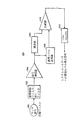
IV Signal Processing FIG. 5 is a schematic diagram of the signal processing elements of the debris sensor subsystem in one practice of the invention.
上述したように、デブリセンサの1の目的は、自律型清浄装置が、デブリを拾い上げたとき、またはデブリのある場所に遭遇したときにそれを感知できるようにすることである。この情報は、清浄行動における変更をするために、または例えば、デブリに遭遇したときの上述したスポット清浄モードのような、選択された動作または行動モードに装置が入るようにするための入力として使用できる。図7に示す非自律型清浄装置においては、デブリセンサ704PSからのデブリ信号706は、ユーザーが認識できる表示灯710を点灯したり(例えば、デブリに遭遇していることをユーザーに信号で伝える)、パワーユニット703から清浄システムへのパワー出力を上げたり、または他の動作の変更または変更の組合せ(例えば、ユーザーが認識できる「高パワー」電灯を点灯して、同時にパワーを上げる)を引き起こすために使用できる。
As mentioned above, one purpose of the debris sensor is to allow the autonomous cleaning device to sense when it picks up or encounters a debris location. This information is used as an input to make changes in the cleaning behavior or to allow the device to enter a selected operation or behavior mode, such as the spot cleaning mode described above when encountering debris, for example. it can. In the non-autonomous cleaning device shown in FIG. 7, the
更に、上述したように、2つのデブリセンサ回路モジュール(つまり、図1の125Lと125Rのような左および右チャネル)は、自律型清浄装置が、清浄ヘッドアセンブリの右側および左側で拾い上げたデブリ量の間の差を感知できるようにするために使用できる。例えば、自律型清浄装置がその左側の先にあるゴミの場所に遭遇すると、左側デブリセンサはデブリの衝突を示し、右側センサは、デブリの衝突を示さない(または示しても少量)。この差分出力は、自律型清浄装置のマイクロプロセッサコントローラ(図1と図2のマイクロプロセッシングユニット135のような)により、装置をデブリの方向へ操縦する(例えば、左側デブリセンサが、右側デブリセンサより高い信号値を生成しているときは、左へ操縦する)、またはデブリの方向のベクトルを選択する、またはスポットカバレッジまたはその他のような移動パターンまたは行動パターンを選択するように使用することができる。
In addition, as described above, the two debris sensor circuit modules (ie, the left and right channels such as 125L and 125R in FIG. 1) are capable of debris volume picked up by the autonomous cleaning device on the right and left sides of the cleaning head assembly. Can be used to be able to perceive the difference between. For example, if the autonomous cleaning device encounters a garbage location ahead of its left side, the left debris sensor indicates a debris collision and the right sensor does not indicate a debris collision (or a small amount if shown). This differential output is driven by a microprocessor controller (such as the
このように、図5は、左側および右側の両チャネルを含むことができるデブリセンササブシステムの1つのチャネル(例えば、左側チャネル)を示している。右側チャネルは、実質的に同一であり、それゆえ、その構造と動作は下記の検討から理解されよう。 Thus, FIG. 5 illustrates one channel (eg, left channel) of the debris sensor subsystem that can include both left and right channels. The right channel is substantially identical and therefore its structure and operation will be understood from the discussion below.
図5に示すように、左側チャネルは、センサ素子(圧電ディスク)402、音響振動フィルタ/RFIフィルタモジュール502、信号増幅器504、基準レベル生成器506、減衰器508、減衰器508と基準レベル生成器506の出力を比較する比較器510、およびパルスストレッチャ512から構成されている。パルスストレッチャ512からの出力は、図2に示されるマイクロプロセッシングユニット135、つまり、動作的行動を選択するときの使用に適しているコントローラのようなシステムコントローラへの論理レベル出力信号である。
As shown in FIG. 5, the left channel includes a sensor element (piezoelectric disk) 402, an acoustic vibration filter /
音響振動フィルタ/RFIフィルタブロック502は、大きな減衰を提供し(1つの実施形態においては、−45dbボルトを超える)、低周波数の、低変化率の機械的信号のほとんどを阻止し、高周波数の、高い変化率のデブリ衝突信号を通過させるように設計することができる。しかし、これらの高周波数信号がフィルタを通過しても、減衰されるので、このように信号増幅器504による増幅が必要になる。
The acoustic vibration filter /
所望の高周波数デブリ衝突信号の増幅に加えて、フィルタを通過する、非常に小さな残留機械的ノイズ信号もまた、増幅器それ自身により生成された電気ノイズと、モーターにより生成され、大気中を放射されるか、またはセンサおよびその導線により拾われたいかなる無線周波数干渉(RFI)成分と共に増幅される。信号増幅器の高周波数応答は、非常に高い周波数RFIの増幅を最小にするように設計されている。この、所望のデブリ衝突信号よりもはるかに低い周波数成分を有する一定バックグラウンドノイズ信号は、基準レベル生成器506に供給される。基準レベル生成器506の目的は、ノイズ信号の瞬間ピーク値、または包絡線に続く基準信号を生成するためである。図5において関心対象の信号、つまり、デブリがセンサに衝突した結果の信号もまたこの基準レベル生成器506に供給される。このように、基準レベル生成器506は、高周波数で、高い変化率のデブリ衝突信号にそれほどすばやく応答しないで、これらの信号の瞬間ピーク値を追尾できるように設計される。結果としての基準信号は、下記に記述するように、比較のために使用される。
In addition to the amplification of the desired high frequency debris collision signal, a very small residual mechanical noise signal passing through the filter is also generated by the motor itself and radiated in the atmosphere by the electrical noise generated by the amplifier itself. Or amplified with any radio frequency interference (RFI) component picked up by the sensor and its leads. The high frequency response of the signal amplifier is designed to minimize the amplification of very high frequency RFI. This constant background noise signal having a frequency component much lower than the desired debris collision signal is provided to the
再び図5を参照して、信号増幅器504からの信号もまた減衰器508に供給されるということが分かる。これは基準レベル生成器506に供給される信号と同じであるので、関心対象の高周波数信号(つまり、デブリがセンサに衝突したときの)および低周波数ノイズの両者を含む復号信号である。減衰器508は、この信号の振幅を減少して、通常は、デブリがセンサ素子に衝突していないときの基準レベル生成器506からの信号の振幅より小さくなる。
Referring again to FIG. 5, it can be seen that the signal from the
比較器510は、減衰器508からの信号の瞬間電圧振幅値を、基準レベル生成器506からの信号と比較する。通常は、清浄装置が動作中で、デブリがセンサ素子に衝突していないときは、基準レベル生成器506から出てくる瞬間電圧は、減衰器508から出てくる電圧よりも高くなる。これにより、比較器510は、高論理レベル信号(論理1)を出力するようになり、その信号は、パルスストレッチャ512により反転されて、低論理レベル(論理0)が生成される。
しかし、デブリがセンサに衝突すると、減衰器508からの電圧は、基準レベル生成器506からの電圧を超え(この回路は、信号増幅器504からの高周波数で、高変化率の信号成分を追尾できないため)、デブリの衝突で生成された信号は、電圧振幅において、音響振動フィルタ502により、より厳しく減衰される一定バックグラウンド機械的ノイズ信号より高くなる。これにより、比較器510が、状態を一時的に論理レベル0に変更する。パルスストレッチャ512は、この非常に短い(典型的に10マイクロ秒未満)事象を、一定1ミリ秒(+0.3mS、−0mS)事象に拡張し、システムコントローラ(例えば、図2のマイクロプロセッシングユニット135)に信号のサンプリングに十分な時間を提供する。
However, when the debris collides with the sensor, the voltage from the
システムコントローラがこの1ミリ秒の論理0パルスを「見る」と、その事象をデブリの衝突と解釈する。 When the system controller "sees" this 1 millisecond logic 0 pulse, it interprets the event as a debris collision.
ここで音響振動フィルタ/RFIフィルタ502のRFIフィルタ部を参照すると、このフィルタは、モーターおよびモーター駆動回路により生成される、非常に高い周波数で放射された電気ノイズ(RFI)を減衰するように機能する。
Referring now to the RFI filter portion of the acoustic vibration filter /
要約すると、センサ素子に接続された例示回路は、振幅と周波数の両者の情報を使用して、デブリの衝突(デブリを拾い上げている清浄装置を示す)を、これもまたセンサ素子により拾い上げられた通常のバックグランド機械的ノイズと、モーターおよびモーター駆動回路により生成された放射無線周波数電気ノイズから区別する。望ましくないが、通常の一定バックグラウンドノイズは、良好な信号対ノイズ比を維持しながら、偽デブリ衝突兆候を回避する動的基準を確立するために使用される。 In summary, the example circuit connected to the sensor element uses both amplitude and frequency information to indicate a debris collision (which indicates a cleaning device picking up the debris), which was also picked up by the sensor element. Distinguish between normal background mechanical noise and radiated radio frequency electrical noise generated by the motor and motor drive circuitry. Although not desirable, normal constant background noise is used to establish a dynamic reference that avoids false debris collision symptoms while maintaining a good signal-to-noise ratio.
実践において、センサ素子用の機械的搭載システム(図4参照)もまた、センサ素子に影響を与える機械的音響ノイズ振動結合を最小にするように設計される。 In practice, the mechanical mounting system for the sensor element (see FIG. 4) is also designed to minimize mechanical acoustic noise vibration coupling that affects the sensor element.
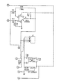
信号処理回路 (図6Aから図6Cで構成される)図6は、典型的なデブリセンサ回路の詳細模式図である。この技術に精通した者には、他の実施形態において、信号処理は、マイクロプロセッシングユニット135のソフトウェア内で部分的にまたは全体的に実行され得るということを理解されよう。図6を参照して、適切な信号処理回路の示された例は、下記の素子を含み、下記の記述に従って動作する。
Signal Processing Circuit (consisting of FIGS. 6A to 6C) FIG. 6 is a detailed schematic diagram of a typical debris sensor circuit. Those skilled in the art will appreciate that in other embodiments, signal processing may be performed partially or entirely within the software of the
圧電センサディスク(図4の圧電ディスク402を参照)からの、グランドを基準にした複合信号は容量C1に供給され、搭載システムを介してセンサに導かれる、低周波数の、音響機械的振動を減衰するように設計された、5極の、ハイパス受動R−Cフィルタに入力される。このフィルタは、21.5kHzの、−100dB/Decade(周波数10倍の変化に対しての減少率)でロールオフする、−3dB折点周波数を有する。このフィルタの出力は、非常に高い周波数RFIのいずれをも減衰するように設計された、単極の、ローパス受動R−Cフィルタに供給される。このフィルタは、1.06MHzの、−20dB/Decadeでロールオフする、−3dB折点周波数を有する。このフィルタの出力はD1とD2によりダイオードクランプされ、センサ素子が、増幅器の供給レールより大きな電圧パルスを生成する厳しい衝突を持続する事象において、U1高電圧遷移から保護する。増幅器チェーンおよび後続の比較器回路用の信号供給動作に要求されるDCバイアスは、R5とR6により生成される。これらの2個の抵抗値は、それらのテブナンインピダンスが、C5と共に作動して、フィルタの5番目の極周波数応答を正しく維持するように選択される。
A composite signal based on ground from a piezoelectric sensor disk (see
U1A、U1B、およびその関連成分は、理論上、441のACゲインの、2段階、ac結合された、非反転増幅器を形成する。C9とC10は、低周波数においてゲインを最小にするように機能し、一方、C7とC8は、RFI周波数においてゲインをロールオフするように機能する。フィルタ入力から増幅器出力への、正味の理論上の周波数応答は、32.5kHz、−100dB/Decadeにおいて−3dBの単極ハイパス応答と、100kHz、−32dB/Decade、および5.4MHz、−100dB/Decadeにおいて、折点周波数を有する2極ローパス応答であり、共にバンドパスフィルタを形成している。 U1A, U1B, and their associated components theoretically form a two-stage, ac-coupled, non-inverting amplifier with an AC gain of 441. C9 and C10 function to minimize gain at low frequencies, while C7 and C8 function to roll off gain at RFI frequencies. The net theoretical frequency response from the filter input to the amplifier output is 32.5 kHz, -100 dB / Decade with a -3 dB single pole high pass response, 100 kHz, -32 dB / Decade, and 5.4 MHz, -100 dB / In Decade, it is a two-pole low-pass response having a break frequency and together forms a band-pass filter.
増幅器からの出力は分割され、1つの出力はR14に入力し、他は、U1Cの非反転入力に入力する。R14に入力する信号は、R14−R15電圧デバイダにより減衰され、比較器U2Aの反転入力に供給される。U1Bの出力からの他の信号分岐は、増幅器U1Cの非反転入力に供給される。U1Dと共にU1C、およびその間の成分(図2に示すように)は、半波長の、正ピーク検出器を形成する。アタックおよびデケイタイムは、それぞれR13とR12により設定される。この回路からの出力は、R16を介して、U2Aの非反転入力に供給される。R16は、R19と共に、スイッチング時間とノイズ免疫性を向上するためにヒステリシスを与える。U2Aは、ピーク検出器の出力と、R14−R15減衰器の間の瞬間値を比較するように機能する。 The output from the amplifier is split and one output is input to R14 and the other is input to the non-inverting input of U1C. The signal input to R14 is attenuated by the R14-R15 voltage divider and supplied to the inverting input of the comparator U2A. The other signal branch from the output of U1B is fed to the non-inverting input of amplifier U1C. U1C along with U1D and the components in between (as shown in FIG. 2) form a half-wave, positive peak detector. The attack and decay times are set by R13 and R12, respectively. The output from this circuit is supplied to the non-inverting input of U2A via R16. R16, along with R19, provides hysteresis to improve switching time and noise immunity. U2A functions to compare the instantaneous value between the output of the peak detector and the R14-R15 attenuator.
通常は、デブリがセンサに衝突していないときは、ピーク検出器の出力は、その振幅が減衰器ネットワークの出力よりも大きくなる。デブリがセンサに衝突すると、低周波数機械的ノイズ信号成分よりも大きく、フロントエンドハイパスフィルタから出て、U1Aに入る振幅を有する、高周波数パルスが生成される。この信号は、その振幅が、ピーク検出器から出る信号よりも、R14-R15減衰器ネットワークから出た後でさえ、より大きくなるが、これは、ピーク検出器が、R13、C11、およびR12のネットワークにおける成分値のために、高速パルスを追尾できないことによる。比較器は、デブリ衝突パルスの振幅が、ピーク検出器から出る、ダイナミックな、ノイズにより生成された、基準レベルの信号より大きい限りは、状態を高から低に変更する。この比較器出力パルスは、システムコントローラが見るためには短すぎるために、パルスストレッチャが使用される。 Normally, when the debris does not strike the sensor, the peak detector output is greater in amplitude than the attenuator network output. When the debris strikes the sensor, a high frequency pulse is generated that has an amplitude that is larger than the low frequency mechanical noise signal component and exits the front end high pass filter and enters U1A. This signal is greater in amplitude than it exits the peak detector, even after leaving the R14-R15 attenuator network, which means that the peak detectors of R13, C11, and R12 This is because high-speed pulses cannot be tracked due to component values in the network. The comparator changes state from high to low as long as the amplitude of the debris collision pulse is greater than the dynamic, noise-generated, reference level signal exiting the peak detector. Since this comparator output pulse is too short for the system controller to see, a pulse stretcher is used.
パルスストレッチャは、ロックアウト機構を有するワンショット単安定設計であり、それにより、タイムアウト期間の最後まで、再トリガを回避する。U2Aからの出力は、C13とQ1の接合点に供給される。C13は信号を、U2Cとその関連成分により形成された単安定に結合する。Q1は、単安定がタイムアウトになるまで、U2Aの出力を低く保つことによりロックアウトとして機能する。タイムアウト期間は、R22、C12,およびR18により形成される時定数と、R20−R21電圧デバイダにより設定される基準レベルにより設定される。この時間は、コントローラ/プロセッサにより使用されるソフトウェアの条件により規定されるように、1mS、+0.3mS、および−0.00mSに対して調整できる。 The pulse stretcher is a one-shot monostable design with a lockout mechanism, thereby avoiding retriggering until the end of the timeout period. The output from U2A is supplied to the junction of C13 and Q1. C13 couples the signal monostable formed by U2C and its related components. Q1 functions as a lockout by keeping U2A output low until monostable times out. The timeout period is set by the time constant formed by R22, C12, and R18 and the reference level set by the R20-R21 voltage divider. This time can be adjusted for 1 mS, +0.3 mS, and -0.00 mS, as defined by the software requirements used by the controller / processor.
デブリセンサ回路のパワーは、U3と関連成分により提供される。U3は、5ボルト出力を提供する低パワー線形調整器である。ロボットに搭載されたバッテリからの非調整電圧は、パワー入力を提供する。 The power of the debris sensor circuit is provided by U3 and related components. U3 is a low power linear regulator that provides a 5 volt output. Unregulated voltage from a battery mounted on the robot provides power input.
必要な場合は、R14とR12により回路調整が設定される。これらの調整により、回路応答を、短時間の間に同調できる。 If necessary, circuit adjustment is set by R14 and R12. With these adjustments, the circuit response can be tuned in a short time.
この種の生成装置においては、デブリセンサ回路プリント回路基板(PCB)へのパワー、およびそこからの信号は、シールドケーブルを介して主基板に転送される。または、ノイズフィルタを、シールドケーブルの使用と置き換えることができ、配線コストが削減される。ケーブルシールドドレインワイヤは、センサ回路PCB側でのみ接地できる。このシールドは、接地電流をまったく搬送しない。ケーブル内の分離された導体が、パワーグランドを搬送する。ノイズ減少のために、生成センサPCBは、底部側に固体接地面を有する上面側にすべての成分を有するべきである。センサPCBは、ロボットモーターからの放射ノイズピックアップから成分をシールドするために、基板の上側をカバーする接地された金属シールドを有する搭載アセンブリに格納されるべきである。圧電センサディスクを、図4に示すような、適切な機械的搭載システム上のセンサ回路PCBの下に搭載することができ、そのことにより、接続リードを、ノイズ免疫性のために可能な限り短く維持することができる。
V.結論
本発明は、デブリの堆積により劣化されることがなく、デブリの衝突の瞬間的に感知して応答でき、従って、床または清浄対象の他の表面上のデブリに直接応答して、大気流の変動、瞬間的なパワー、または清浄装置の他の動作状態に対しては、低感度のデブリセンサを提供する。
In this type of generator, power to the debris sensor circuit printed circuit board (PCB) and signals from it are transferred to the main board via a shielded cable. Alternatively, the noise filter can be replaced with the use of a shielded cable, reducing the wiring cost. The cable shield drain wire can be grounded only on the sensor circuit PCB side. This shield does not carry any ground current. Separate conductors in the cable carry the power ground. For noise reduction, the production sensor PCB should have all components on the top side with a solid ground plane on the bottom side. The sensor PCB should be housed in a mounting assembly with a grounded metal shield that covers the top side of the substrate to shield components from radiated noise pickup from the robot motor. The piezoelectric sensor disk can be mounted under the sensor circuit PCB on a suitable mechanical mounting system, as shown in FIG. 4, so that the connection leads are as short as possible for noise immunity. Can be maintained.
V. CONCLUSION The present invention is capable of instantaneously sensing and responding to debris collisions without being degraded by debris deposition, and thus responding directly to debris on the floor or other surface to be cleaned. For low fluctuations, instantaneous power, or other operating conditions of the cleaning device, a low sensitivity debris sensor is provided.
ここで記述したように採用されると、本発明により、自律型清浄装置は、その動作を制御し、または例えば、デブリセンサにより生成された信号に基づいて、より「汚れた」場所へ装置を向かうように操縦するような、検出されたデブリに応答する複数の動作モード、移動パターン、または行動の中から選択することができる。 When employed as described herein, according to the present invention, an autonomous cleaning device controls its operation or, for example, directs the device to a more “dirty” location based on a signal generated by a debris sensor. Can be selected from a plurality of operating modes, movement patterns, or behaviors that respond to detected debris.
デブリセンサはまた、非自律型清浄装置にも採用でき、自律型または非自律型清浄装置の何れかの動作モードを制御し、選択し、または変更することができる。 The debris sensor can also be employed in a non-autonomous cleaning device and can control, select or change the mode of operation of either the autonomous or non-autonomous cleaning device.
更に、開示された信号処理アーキテクチャおよび回路は、特に、圧電デブリセンサと組み合わせると有効であり、高い信号対ノイズ比を提供する。 Furthermore, the disclosed signal processing architecture and circuit is particularly effective in combination with a piezoelectric debris sensor and provides a high signal to noise ratio.
この技術に精通した者は、本発明の広い範囲での変更および変形が、本発明の範囲において可能であることを認識できよう。デブリセンサはまた、ここで記述した以外の目的および装置にも採用できる。従って、上述した内容は、単に例として提示されたにすぎず、本発明の範囲は、付随する請求項によってのみ制限される。 Those skilled in the art will recognize that variations and modifications of the broad scope of the invention are possible within the scope of the invention. Debris sensors can also be employed for purposes and devices other than those described herein. Accordingly, what has been described above is provided by way of example only and the scope of the present invention is limited only by the accompanying claims.
Claims (1)
デブリを移送するための清浄経路と、
デブリを前記清浄経路へ向かって掃き上げるように動作可能なブラシアセンブリと、
前記清浄経路に近接して、前記ブラシアセンブリによって掃き上げられるデブリが衝突する場所に位置し、デブリに衝突したことに応答して、該衝突を示すデブリ信号を生成するデブリセンサと、
前記デブリ信号に応答して、前記清浄装置の動作モードを変更するプロセッサと、
を備え、
前記デブリセンサは、
前記清浄装置の移動により生じるバックグラウンド機械的ノイズおよび電気的ノイズに相当する周波数成分を減衰するフィルタと、
前記フィルタからの出力における振幅情報から、前記デブリの衝突の発生を判断する判断部と、を備えることを特徴とする、清浄装置。
A cleaning device,
A clean path for transporting debris;
A brush assembly operable to sweep debris toward the cleaning path;
A debris sensor located in a location where the debris swept by the brush assembly collides in proximity to the cleaning path and generates a debris signal indicative of the collision in response to the collision with the debris;
A processor for changing an operation mode of the cleaning device in response to the debris signal;
With
The debris sensor
A filter that attenuates frequency components corresponding to background mechanical noise and electrical noise caused by movement of the cleaning device;
And a determination unit that determines occurrence of collision of the debris from amplitude information in an output from the filter.
Priority Applications (1)
| Application Number | Priority Date | Filing Date | Title |
|---|---|---|---|
| JP2012047075A JP5457485B2 (en) | 2012-03-02 | 2012-03-02 | Cleaning device with debris sensor |
Applications Claiming Priority (1)
| Application Number | Priority Date | Filing Date | Title |
|---|---|---|---|
| JP2012047075A JP5457485B2 (en) | 2012-03-02 | 2012-03-02 | Cleaning device with debris sensor |
Related Parent Applications (1)
| Application Number | Title | Priority Date | Filing Date |
|---|---|---|---|
| JP2010130902A Division JP5025762B2 (en) | 2010-06-08 | 2010-06-08 | Debris sensor for cleaning equipment |
Related Child Applications (1)
| Application Number | Title | Priority Date | Filing Date |
|---|---|---|---|
| JP2013241021A Division JP5756844B2 (en) | 2013-11-21 | 2013-11-21 | Cleaning device with debris sensor |
Publications (3)
| Publication Number | Publication Date |
|---|---|
| JP2012106080A true JP2012106080A (en) | 2012-06-07 |
| JP2012106080A5 JP2012106080A5 (en) | 2012-07-19 |
| JP5457485B2 JP5457485B2 (en) | 2014-04-02 |
Family
ID=46492329
Family Applications (1)
| Application Number | Title | Priority Date | Filing Date |
|---|---|---|---|
| JP2012047075A Expired - Lifetime JP5457485B2 (en) | 2012-03-02 | 2012-03-02 | Cleaning device with debris sensor |
Country Status (1)
| Country | Link |
|---|---|
| JP (1) | JP5457485B2 (en) |
Cited By (2)
| Publication number | Priority date | Publication date | Assignee | Title |
|---|---|---|---|---|
| JP2015154965A (en) * | 2015-04-20 | 2015-08-27 | アイロボット コーポレイション | Cleaning apparatus with debris sensor |
| JP2016201095A (en) * | 2015-04-09 | 2016-12-01 | アイロボット コーポレイション | Restricting movement of mobile robot |
Citations (12)
| Publication number | Priority date | Publication date | Assignee | Title |
|---|---|---|---|---|
| JPS61130147U (en) * | 1985-02-04 | 1986-08-14 | ||
| JPH0339126A (en) * | 1989-07-05 | 1991-02-20 | Matsushita Electric Ind Co Ltd | Control circuit of vacuum cleaner |
| JPH03173519A (en) * | 1989-12-04 | 1991-07-26 | Mitsubishi Electric Home Appliance Co Ltd | Mobile cleaner |
| JPH03242710A (en) * | 1990-02-21 | 1991-10-29 | Sanyo Electric Co Ltd | Running control system for cleaning robot |
| JPH0638912A (en) * | 1992-07-22 | 1994-02-15 | Matsushita Electric Ind Co Ltd | Dust detecting device for vacuum cleaner |
| JPH0759702A (en) * | 1993-08-24 | 1995-03-07 | Matsushita Electric Ind Co Ltd | Mobile electric vacuum cleaner |
| JPH07334242A (en) * | 1994-06-06 | 1995-12-22 | Matsushita Electric Ind Co Ltd | Mobile working robot |
| JP2001087182A (en) * | 1999-09-20 | 2001-04-03 | Mitsubishi Electric Corp | Vacuum cleaner |
| JP2002165731A (en) * | 2000-11-29 | 2002-06-11 | Mitsubishi Electric Corp | Vacuum cleaner |
| JP2003047579A (en) * | 2001-08-06 | 2003-02-18 | Toshiba Tec Corp | Vacuum cleaner |
| JP2003050632A (en) * | 2001-08-08 | 2003-02-21 | Toshiba Tec Corp | Autonomous moving device and cleaning device equipped with the same device |
| JP2003114719A (en) * | 2001-08-03 | 2003-04-18 | Sanyo Electric Co Ltd | Mobile robot |
-
2012
- 2012-03-02 JP JP2012047075A patent/JP5457485B2/en not_active Expired - Lifetime
Patent Citations (12)
| Publication number | Priority date | Publication date | Assignee | Title |
|---|---|---|---|---|
| JPS61130147U (en) * | 1985-02-04 | 1986-08-14 | ||
| JPH0339126A (en) * | 1989-07-05 | 1991-02-20 | Matsushita Electric Ind Co Ltd | Control circuit of vacuum cleaner |
| JPH03173519A (en) * | 1989-12-04 | 1991-07-26 | Mitsubishi Electric Home Appliance Co Ltd | Mobile cleaner |
| JPH03242710A (en) * | 1990-02-21 | 1991-10-29 | Sanyo Electric Co Ltd | Running control system for cleaning robot |
| JPH0638912A (en) * | 1992-07-22 | 1994-02-15 | Matsushita Electric Ind Co Ltd | Dust detecting device for vacuum cleaner |
| JPH0759702A (en) * | 1993-08-24 | 1995-03-07 | Matsushita Electric Ind Co Ltd | Mobile electric vacuum cleaner |
| JPH07334242A (en) * | 1994-06-06 | 1995-12-22 | Matsushita Electric Ind Co Ltd | Mobile working robot |
| JP2001087182A (en) * | 1999-09-20 | 2001-04-03 | Mitsubishi Electric Corp | Vacuum cleaner |
| JP2002165731A (en) * | 2000-11-29 | 2002-06-11 | Mitsubishi Electric Corp | Vacuum cleaner |
| JP2003114719A (en) * | 2001-08-03 | 2003-04-18 | Sanyo Electric Co Ltd | Mobile robot |
| JP2003047579A (en) * | 2001-08-06 | 2003-02-18 | Toshiba Tec Corp | Vacuum cleaner |
| JP2003050632A (en) * | 2001-08-08 | 2003-02-21 | Toshiba Tec Corp | Autonomous moving device and cleaning device equipped with the same device |
Cited By (6)
| Publication number | Priority date | Publication date | Assignee | Title |
|---|---|---|---|---|
| JP2016201095A (en) * | 2015-04-09 | 2016-12-01 | アイロボット コーポレイション | Restricting movement of mobile robot |
| US10639793B2 (en) | 2015-04-09 | 2020-05-05 | Irobot Corporation | Restricting movement of a mobile robot |
| JP2020126691A (en) * | 2015-04-09 | 2020-08-20 | アイロボット・コーポレーション | Movable robot movement restriction |
| US11465284B2 (en) | 2015-04-09 | 2022-10-11 | Irobot Corporation | Restricting movement of a mobile robot |
| JP7184435B2 (en) | 2015-04-09 | 2022-12-06 | アイロボット・コーポレーション | Restrictions on movement of mobile robots |
| JP2015154965A (en) * | 2015-04-20 | 2015-08-27 | アイロボット コーポレイション | Cleaning apparatus with debris sensor |
Also Published As
| Publication number | Publication date |
|---|---|
| JP5457485B2 (en) | 2014-04-02 |
Similar Documents
| Publication | Publication Date | Title |
|---|---|---|
| US10182693B2 (en) | Debris sensor for cleaning apparatus | |
| JP2007519468A (en) | Debris sensor for cleaning equipment | |
| JP5756844B2 (en) | Cleaning device with debris sensor | |
| JP5457485B2 (en) | Cleaning device with debris sensor | |
| JP5025762B2 (en) | Debris sensor for cleaning equipment | |
| JP2018086499A (en) | Cleaning device provided with debris sensor | |
| JP5465709B2 (en) | Autonomous cleaning device | |
| JP4959759B2 (en) | Method for operating debris sensor and cleaning device | |
| JP7033821B2 (en) | Cleaning device with debris sensor | |
| JP2016052607A (en) | Cleaning device provided with debris sensor | |
| JP2015154965A (en) | Cleaning apparatus with debris sensor | |
| AU2016265962B2 (en) | Debris sensor for cleaning apparatus | |
| KR20070003863A (en) | Debris sensor for cleaning apparatus |
Legal Events
| Date | Code | Title | Description |
|---|---|---|---|
| A621 | Written request for application examination |
Free format text: JAPANESE INTERMEDIATE CODE: A621 Effective date: 20120313 |
|
| A521 | Request for written amendment filed |
Free format text: JAPANESE INTERMEDIATE CODE: A523 Effective date: 20120523 |
|
| A977 | Report on retrieval |
Free format text: JAPANESE INTERMEDIATE CODE: A971007 Effective date: 20130521 |
|
| A131 | Notification of reasons for refusal |
Free format text: JAPANESE INTERMEDIATE CODE: A131 Effective date: 20130524 |
|
| A601 | Written request for extension of time |
Free format text: JAPANESE INTERMEDIATE CODE: A601 Effective date: 20130813 |
|
| A602 | Written permission of extension of time |
Free format text: JAPANESE INTERMEDIATE CODE: A602 Effective date: 20130816 |
|
| A601 | Written request for extension of time |
Free format text: JAPANESE INTERMEDIATE CODE: A601 Effective date: 20130918 |
|
| A602 | Written permission of extension of time |
Free format text: JAPANESE INTERMEDIATE CODE: A602 Effective date: 20130924 |
|
| A601 | Written request for extension of time |
Free format text: JAPANESE INTERMEDIATE CODE: A601 Effective date: 20131011 |
|
| A602 | Written permission of extension of time |
Free format text: JAPANESE INTERMEDIATE CODE: A602 Effective date: 20131017 |
|
| A521 | Request for written amendment filed |
Free format text: JAPANESE INTERMEDIATE CODE: A523 Effective date: 20131121 |
|
| TRDD | Decision of grant or rejection written | ||
| A01 | Written decision to grant a patent or to grant a registration (utility model) |
Free format text: JAPANESE INTERMEDIATE CODE: A01 Effective date: 20131212 |
|
| A61 | First payment of annual fees (during grant procedure) |
Free format text: JAPANESE INTERMEDIATE CODE: A61 Effective date: 20140109 |
|
| R150 | Certificate of patent or registration of utility model |
Ref document number: 5457485 Country of ref document: JP Free format text: JAPANESE INTERMEDIATE CODE: R150 Free format text: JAPANESE INTERMEDIATE CODE: R150 |
|
| R250 | Receipt of annual fees |
Free format text: JAPANESE INTERMEDIATE CODE: R250 |
|
| R250 | Receipt of annual fees |
Free format text: JAPANESE INTERMEDIATE CODE: R250 |
|
| R250 | Receipt of annual fees |
Free format text: JAPANESE INTERMEDIATE CODE: R250 |
|
| R250 | Receipt of annual fees |
Free format text: JAPANESE INTERMEDIATE CODE: R250 |
|
| R250 | Receipt of annual fees |
Free format text: JAPANESE INTERMEDIATE CODE: R250 |
|
| R250 | Receipt of annual fees |
Free format text: JAPANESE INTERMEDIATE CODE: R250 |
|
| R250 | Receipt of annual fees |
Free format text: JAPANESE INTERMEDIATE CODE: R250 |
|
| R250 | Receipt of annual fees |
Free format text: JAPANESE INTERMEDIATE CODE: R250 |