JP2012103019A - Reaction plate assembly, reaction plate, and nucleic acid analyzer - Google Patents
Reaction plate assembly, reaction plate, and nucleic acid analyzer Download PDFInfo
- Publication number
- JP2012103019A JP2012103019A JP2010249275A JP2010249275A JP2012103019A JP 2012103019 A JP2012103019 A JP 2012103019A JP 2010249275 A JP2010249275 A JP 2010249275A JP 2010249275 A JP2010249275 A JP 2010249275A JP 2012103019 A JP2012103019 A JP 2012103019A
- Authority
- JP
- Japan
- Prior art keywords
- reaction
- reaction plate
- plate
- circumference
- radius
- Prior art date
- Legal status (The legal status is an assumption and is not a legal conclusion. Google has not performed a legal analysis and makes no representation as to the accuracy of the status listed.)
- Pending
Links
Images


Abstract
Description
本発明は、生物学的試料に含まれる核酸を増幅することによって生物学的試料を分析するための核酸分析装置及びそれに用いる器具に関する。 The present invention relates to a nucleic acid analyzer for analyzing a biological sample by amplifying a nucleic acid contained in the biological sample and an instrument used therefor.
血液、血漿、組織片などの生物学的試料に含まれる核酸の分析は、生物学、生化学、医学などの学術研究ばかりでなく、診断、農作物の品種改良、食品検査といった産業など多岐の分野で行われている。核酸の分析方法としてもっとも広く普及している方法はPCR(Polymerase Chain Reaction)と呼ばれる、分析したい領域の核酸を塩基配列特異的に増幅させる技術である。PCRの応用として、分析したい核酸に蛍光ラベルを付加し、励起光を照射して経時的に蛍光強度を測定することで、微量の核酸を高感度に検出することも可能である。 Analysis of nucleic acids contained in biological samples such as blood, plasma, and tissue fragments not only in academic research such as biology, biochemistry, and medicine, but also in various fields including industries such as diagnosis, crop varieties improvement, and food inspection It is done in The most widely used method for analyzing nucleic acids is a technique called PCR (Polymerase Chain Reaction), which specifically amplifies the nucleic acid in the region to be analyzed. As an application of PCR, it is possible to detect a very small amount of nucleic acid with high sensitivity by attaching a fluorescent label to the nucleic acid to be analyzed, irradiating excitation light and measuring the fluorescence intensity over time.
PCRでは、核酸とそれを増幅させるための試薬を含む溶液を、95℃程度に加熱して核酸を熱変性させ、その後60℃程度まで冷却して核酸のアニーリングと伸長反応を進めるというサイクルが30〜40回繰り返される。現在主流のPCR装置では、96〜386個の反応ウエルを有するマイクロタイタープレートと呼ばれる反応プレートをペルチェ素子上に配置し、ペルチェ素子の温度を上下させることで温度サイクルを与えている。この方法では、ペルチェ素子そのものの温度変化に時間を要するため、分析時間の短縮に向けた大きな課題となっていた。 In PCR, a solution containing a nucleic acid and a reagent for amplifying it is heated to about 95 ° C to thermally denature the nucleic acid, and then cooled to about 60 ° C to proceed with nucleic acid annealing and extension reaction. Repeated ~ 40 times. In the current mainstream PCR apparatus, a reaction plate called a microtiter plate having 96 to 386 reaction wells is arranged on a Peltier element, and a temperature cycle is given by raising and lowering the temperature of the Peltier element. In this method, since it takes time to change the temperature of the Peltier element itself, it has been a big problem for shortening the analysis time.
また、上記の方法では、96〜386個の反応ウエルにセットした複数の試料を一括で処理するバッチ処理にならざるを得ず、一旦処理が開始されるとそのバッチが終了するまで次の処理が開始できないという課題もあった。 In addition, in the above method, it is necessary to perform batch processing in which a plurality of samples set in 96 to 386 reaction wells are processed at once. Once processing is started, the next processing is completed until the batch is completed. There was also a problem that could not start.
非特許文献1には、温度サイクルの高速化に対する課題を解決するために、予め複数の温度に設定したヒータ上を、反応ウエルを有するディスク型の反応プレートが接触回転する構造が開示されている。この例では、ヒータを温度変化させる必要が無くなり、反応プレートの温度変化を迅速に行うことが可能となる。また、上面、下面側に配置された温度調節装置からの熱を受け取り易くするために、サンプル溶液を平面方向に広げる工夫もされている。
Non-Patent
特許文献1には、複数のウエルを備えた円板状のマイクロチップを回転させる機構を備えた温度制御装置の例が記載されている。特許文献2には、扇状のプレートインサートをディスクアッセイプレートに装填するように構成された装置が記載されている。
従来の核酸分析装置では、装填した反応プレートの分析が終了するまでは、次の反応プレートを装填することができなかった。また、随時、反応プレートを装填し、随時、反応プレートをアンロードすることができなかった。従来の核酸分析装置は、反応プレートのローディング及びアンローディングの自由度が高くないため、効率的に核酸分析を行うことができなかった。 In the conventional nucleic acid analyzer, the next reaction plate cannot be loaded until the analysis of the loaded reaction plate is completed. In addition, the reaction plate was loaded at any time, and the reaction plate could not be unloaded at any time. Conventional nucleic acid analyzers cannot perform nucleic acid analysis efficiently because the degree of freedom in loading and unloading reaction plates is not high.
本発明の目的は、核酸分析において、反応プレートのローディング及びアンローディングの自由度が高く、効率的に試料を分析することができる技術を提供することにある。 An object of the present invention is to provide a technique capable of efficiently analyzing a sample with a high degree of freedom in loading and unloading of a reaction plate in nucleic acid analysis.
本発明によると、反応プレートアセンブリは、一つ以上の反応ウエルを有する反応プレートと、反応ウエルを覆うように反応プレートに装着された可視光透過可能なカバーと、カバーを覆うように装着された可視光透過可能な重り部材と、を有する。反応ウエルは所定の半径r1の円の円周に沿って円弧状に配置されている。 According to the present invention, a reaction plate assembly is mounted to cover a reaction plate having one or more reaction wells, a visible light transmissive cover mounted on the reaction plate so as to cover the reaction well, and a cover. A weight member capable of transmitting visible light. The reaction wells are arranged in an arc along the circumference of a circle with a predetermined radius r1.
本発明によると、核酸分析において、反応プレートのローディング及びアンローディングの自由度が高く、効率的に試料を分析することができる技術を提供する。 According to the present invention, there is provided a technique capable of efficiently analyzing a sample with a high degree of freedom in loading and unloading a reaction plate in nucleic acid analysis.
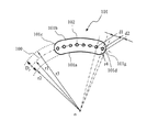
図1は、本発明による反応プレートの第1の実施形態を示す平面図である。反応プレート101には複数の反応ウエル102が形成されている。本例では、反応ウエル102の数は、8個であるが、もちろん、それよりも多くても構わないし、少なくても構わない。本例では、反応ウエル102の平面形状は、円であるが、楕円、四角形、又は、多角形であっても構わない。反応ウエル102は、中心をoとし、半径r1の円周100に沿って形成されている。本例では、隣り合う2つの反応ウエル102の中心間の間隔d1は全て一定である。核酸分析装置において、反応ウエル102の蛍光強度を測定する際に、間隔d1が一定である方が、信号処理が容易となるためである。しかしながら、間隔d1は一定でなくてもよい。
FIG. 1 is a plan view showing a first embodiment of a reaction plate according to the present invention. A plurality of
反応プレート101は幅Dの帯状に且つ円弧状に形成されている。反応プレート101の外形は、内周側の境界101a、外周側の境界101b、両側の半円状の境界101c、101dからなる。内周側の境界101aは、中心をoとし半径r2の円周の一部であり、外周側の境界101bは、中心をoとし半径r3の円周の一部である。両側の半円状の境界101c、101dは、円周100上に中心を有する半径r4の円周の一部である。反応プレート101の幅Dは、D=r3−r2である。反応ウエル102は、好ましくは、反応プレート101の幅Dの中心に配置される。この場合、r3−r1=r1−r2=D/2である。両側の半円状の境界101c、101dは、半径D/2の円周の一部であってよい。この場合、r4=D/2ある。
The
複数の反応プレート101を、円周100に沿って並べたとき、全ての反応ウエルが等間隔d1に配置されることが好ましい。更に、隣接する2つの反応プレート101の間に僅かな隙間を設けることが好ましい。そのための条件を説明する。右側の半円状の境界101dと円周100の交点を101gとする。反応プレート101の反応ウエルのうち、右端の反応ウエルの中心と交点101gの間の距離をd2とする。d2をd1の半分以下とするとよい。それによって、複数の反応プレート101を円周方向に沿って並べたとき、全ての反応ウエルは等間隔d1に配置される。左側の半円状の境界101dと左端の反応ウエルの間の距離についても同様である。
When a plurality of
図2は、本発明による核酸分析装置の平面構成を模式的に示す。本例の核酸分析装置は、PCRを行うことができるように構成されている。本例の核酸分析装置は、円周に沿って配置された8個の温度調節装置20A〜20Hを有する。8個の温度調節装置20A〜20Hの上に、8個の反応プレートアセンブリ10A〜10Hが配置されている。反応プレートアセンブリ10A〜10Hの各々は、反応プレートとその上に配置された透明なカバーと更にその上に配置された透明な重り部材を有する。ここでは、透明なカバー及び透明な重り部材の図示は省略されている。反応プレートの上に設けられた反応ウエル102が図示されている。尚、温度調節装置20A〜20Hの上に、反応プレートアセンブリ10A〜10Hを配置する代わりに、反応プレートを直接、配置してもよい。
FIG. 2 schematically shows a planar configuration of the nucleic acid analyzer according to the present invention. The nucleic acid analyzer of this example is configured to perform PCR. The nucleic acid analyzer of this example has eight
8個の温度調節装置20A〜20Hの形状及び寸法は同一であってよい。各温度調節装置の形状及び寸法と、反応プレートアセンブリ10A〜10Hの形状及び寸法は、互いに整合している。例えば、反応プレートアセンブリ10A〜10Hの円周方向の寸法は、温度調節装置20A〜20Hの円周方向の寸法に整合している。即ち、反応プレートアセンブリ10A〜10Hの円周方向の寸法は、温度調節装置20A〜20Hの円周方向の寸法と同一であるか又はそれより僅かに小さい。
The eight
図示のように、反応プレートアセンブリ10A〜10Hは、複数の反応ウエル102が中心をoとし半径r1の円周100に沿って1列に配置されるように、温度調節装置の上に配置される。ここで、全ての反応ウエル102は、中心をoとし半径r1の円周100に沿って、等間隔にて配置されている。
As shown in the figure, the
反応プレートアセンブリ10A〜10Hは、図示されていない回転機構によって、8個の温度調節装置の上を、所定の速度にて移動する。反応プレートアセンブリが温度調節装置の上を円周方向に沿って移動するとき、全ての反応ウエルは、半径r1の円周100に沿って所定の速度にて移動する。反応プレートアセンブリ10A〜10Hが温度調節装置の上を移動している間、反応プレートは温度調節装置と熱的に接触している。従って、反応プレートは温度調節装置によって所望の温度に保持される。
The
本例の核酸分析装置には、反応プレートアセンブリを温度調節装置の上に搬入する搬入駆動機構と、反応プレートアセンブリを温度調節装置の上から排出する排出駆動機構が設けられている。搬入駆動機構及び排出駆動機構は、反応プレートアセンブリを半径方向に沿って搬入及び排出するように構成されている。本例の核酸分析装置では、反応プレートアセンブリは、8個の温度調節装置の上に配置されている。そのため、搬入駆動機構及び排出駆動機構は、回転機構の回転を停止させることなく、反応プレートアセンブリの搬入及び排出を行うことができる。 The nucleic acid analyzer of this example is provided with a loading drive mechanism for loading the reaction plate assembly onto the temperature control device and a discharge drive mechanism for discharging the reaction plate assembly from the temperature control device. The carry-in drive mechanism and the discharge drive mechanism are configured to carry in and discharge the reaction plate assembly along the radial direction. In the nucleic acid analyzer of this example, the reaction plate assembly is disposed on eight temperature controllers. Therefore, the carry-in drive mechanism and the discharge drive mechanism can carry in and discharge the reaction plate assembly without stopping the rotation of the rotation mechanism.
第8の温度調節装置20Hの上方に検出装置23が配置されている。検出装置23は、反応ウエル102へ励起光を照射し、反応ウエル102からの蛍光の強度を測定する光学的検査装置であってよい。尚、複数の検出装置23を設けることにより、複数の色素の発光を検出することができる。
The
反応プレートアセンブリが第8の温度調節装置20Hの上をスライドするとき、反応プレートアセンブリの複数の反応ウエルは、検出装置23の直下を通過する。即ち、検出装置23の検出部は、反応プレートアセンブリの複数の反応ウエルを光学的に検出することができるように、半径r1の円周100の上に配置されてよい。
When the reaction plate assembly slides over the eighth
全ての反応ウエル102は、検出装置23の下を通るから、検出装置23を移動させることなく、全ての反応ウエル102の蛍光強度測定が可能となる。回転機構の回転中であっても、検出装置23の検査部と反応プレートの反応ウエル102の位置は、整合している。本例の核酸分析装置では、回転機構の回転を停止させることなく、検出装置23によって反応ウエル102に装填された試料を光学的に検出することができる。
Since all the
8個の温度調節装置20A〜20Hは、独立に温度制御される。即ち、8個の温度調節装置20A〜20Hは、独立に所定の温度サイクルに従って、温度調節される。例えば、反応プレートアセンブリ10A〜10Hの各々が8個の温度調節装置20A〜20Hの上を、円周方向に沿って、一周することにより、PCRの1温度サイクルを実行するように、温度設定をすることができる。例えば、第1及び第2の温度調節装置20A、20Bの温度を95℃、第3〜第8の温度調節装置20C〜20Hの温度を60℃に設定してよい。反応プレートアセンブリが、第1及び第2の温度調節装置20A、20Bの上を移動している間に、核酸が熱変性し、第3〜第8の温度調節装置20C〜20Hの上を移動している間に、核酸のアニーリングと伸長反応が進行する。
The eight
図3を参照して説明する。本例では、8個の温度調節装置20A〜20Hに、3個の反応プレートアセンブリ10A〜10Cが装填されている。図示の例では、3個の反応プレートアセンブリ10A〜10Cは、互いに隣接して配置されている。しかしながら、3個の反応プレートアセンブリ10A〜10Cは、互いに分離して配置してもよい。本例の核酸分析装置では、8個以下の任意の数の反応プレートアセンブリ10A〜10Cを装填することができる。
This will be described with reference to FIG. In this example, three
PCR(ポリメラーゼ連鎖反応)が開始されると、3個の反応プレートアセンブリ10A〜10Cに対して、温度サイクルを30〜40回、繰り返す必要がある。本例によると、更に5個の反応プレートアセンブリを追加することができる。例えば、3個の反応プレートアセンブリ10A〜10Cに対して、温度サイクルを供したのちに、更に、別のサンプルの分析を行いたい場合がある。このような場合には、反応プレートアセンブリを追加すればよい。また、所定回数の温度サイクルが終了した反応プレートアセンブリは、随時、排出することができる。
When PCR (polymerase chain reaction) is initiated, the temperature cycle must be repeated 30-40 times for the three
本例の核酸分析装置では、分析したいサンプル数に応じて反応プレートアセンブリ10A〜10Cの数を自由に変更することができる。そのため、従来の技術のように、ディスク型反応プレートを用いて、複数のサンプルをバッチ処理する場合と比べると、反応プレートの無駄を軽減することが可能となる。本例の核酸分析装置では、一度分析が開始されるとその分析が終了するまで次の分析が開始できないという不便は解消される。従って、不要な待機時間を無くすことが可能となる。
In the nucleic acid analyzer of this example, the number of
本例の核酸分析装置では、従来の技術と比べて、反応プレートのローディング及びアンローディングの自由度が高くなる利点がある。これについて説明する。 The nucleic acid analyzer of this example has an advantage that the degree of freedom of loading and unloading of the reaction plate is higher than in the conventional technique. This will be described.
本例の核酸分析装置では、反応プレートアセンブリ又は反応プレートは、8個の温度調節装置の上に配置されている。そのため、搬入駆動機構及び排出駆動機構は、回転機構の回転を停止させることなく、反応プレートアセンブリ又は反応プレートの搬入及び排出を行うことができる。更に、本例の反応プレートアセンブリ又は反応プレートでは、反応ウエル102が円周に沿って配置されている。従って、回転機構を停止させることなく、検出装置23によって反応ウエル102の試料を光学的に検出することができる。即ち、本例の核酸分析装置では、回転機構を停止させることなく、常に、一定の速度にて、反応プレートアセンブリ又は反応プレートを回転させることができる。従って、逐次、又は、随時、反応プレートアセンブリ又は反応プレートを装填しても、同一の温度サイクルを付与することができる。こうして本発明によると、反応プレートアセンブリ又は反応プレートを、逐次、又は、随時、装填することができる。
In the nucleic acid analyzer of this example, the reaction plate assembly or reaction plate is disposed on eight temperature control devices. Therefore, the carry-in drive mechanism and the discharge drive mechanism can carry in and discharge the reaction plate assembly or the reaction plate without stopping the rotation of the rotation mechanism. Furthermore, in the reaction plate assembly or reaction plate of this example, the
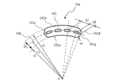
図4は、本発明による反応プレートの第2の実施形態を示す平面図である。本例の反応プレートでは、反応ウエル102の平面形状は、円弧状に湾曲した長円であるが、円弧状に湾曲した長方形又は細長い多角形であってもよい。長円の長手方向の径は、中心をoとし、半径r1の円周100に沿って延びている。本例の反応プレートは、反応ウエルの形状が、長円である点以外は、図1の第1の実施形態と同様であってよい。例えば、隣り合う2つの反応ウエル102の中心間の間隔d1は全て一定とするとよい。
FIG. 4 is a plan view showing a second embodiment of the reaction plate according to the present invention. In the reaction plate of this example, the planar shape of the reaction well 102 is an ellipse curved in an arc shape, but may be a rectangular shape or an elongated polygon curved in an arc shape. The diameter of the ellipse in the longitudinal direction extends along the
複数の反応プレート101を、円周100に沿って並べたとき、全ての反応ウエルが等間隔d1に配置されることが好ましい。更に、隣接する2つの反応プレート101の間に僅かな隙間を設けることが好ましい。そのための条件を説明する。右側の半円状の境界101dと円周100の交点を101gとする。反応プレート101の反応ウエルのうち、右端の反応ウエルの中心と交点101gの間の距離をd2とする。d2をd1の半分以下とするとよい。それによって、複数の反応プレート101を円周方向に沿って並べたとき、全ての反応ウエルは等間隔d1に配置される。左側の半円状の境界101cと左端の反応ウエルの間の距離についても同様である。
When a plurality of
本例の反応プレート101では、反応ウエル102は、円弧状に湾曲した細長い形状であるから、検出装置23を通過する時間が比較的長くなる。従って、検出装置23によって各反応ウエル102を観察する時間は長くなる。そのため、検出装置23による検出精度を向上させることができる。
In the
図5は、本発明による反応プレートの第3の実施形態を示す平面図である。本例の反応プレート101は幅Dの帯状に且つ直線状に形成されている。反応プレート101は、角部が面取りされた長方形である。反応プレート101の外形は、内側の境界101a、外側の境界101b、両側の直線状の境界101c、101dからなる。4つの面取りされた角部は、半径r5の円周の一部である。尚、両側の直線状の境界101c、101dの代わりに、図1に示す第1の実施形態のように、半円状の境界101c、101dとしてもよい。
FIG. 5 is a plan view showing a third embodiment of the reaction plate according to the present invention. The
本例では、反応ウエル102の平面形状は、円であるが、楕円、四角形、又は、多角形であっても構わない。反応ウエル102は、中心をoとし、半径r1の円周100に沿って形成されている。本例では、隣り合う2つの反応ウエル102の中心間の間隔d1は、好ましくは、全て一定である。
In this example, the planar shape of the reaction well 102 is a circle, but it may be an ellipse, a rectangle, or a polygon. The reaction well 102 is formed along a
複数の反応プレート101を、円周100に沿って並べたとき、全ての反応ウエルが等間隔d1に配置されることが好ましい。更に、隣接する2つの反応プレート101の間に僅かな隙間を設けることが好ましい。そのための条件を説明する。右側の半円状の境界101dと円周100の交点を101gとする。反応プレート101の反応ウエルのうち、右端の反応ウエルの中心と交点101gの間の距離をd2とする。d2をd1の半分以下とするとよい。それによって、複数の反応プレート101を円周方向に沿って並べたとき、全ての反応ウエルは等間隔d1に配置される。左側の半円状の境界101cと左端の反応ウエルの間の距離についても同様である。
When a plurality of
図6は、本発明による反応プレートの第4の実施形態を示す平面図である。基本的な構造は図5に示した第3の実施形態と同様であるが、本例では、両端の反応ウエルが設けられていない。例えば、右端の位置101fに設けられるはずの反応ウエルが省略されている。その代わりに、両端にそれぞれ2つの孔103が形成されている。本例では孔103は4個であるが、それより多くても構わないし、少なくても構わない。また、本例では、孔103の平面形状は円であるが、多角形であっても構わない。孔103は、貫通孔であってもよいが、非貫通孔、即ち、有底穴であってもよい。孔103の機能は後に説明する。
FIG. 6 is a plan view showing a fourth embodiment of the reaction plate according to the present invention. The basic structure is the same as that of the third embodiment shown in FIG. 5, but in this example, reaction wells at both ends are not provided. For example, the reaction well that should be provided at the
本例でも、反応プレート101上の隣り合う2つの反応ウエル102の中心間の間隔d1は全て一定とするとよい。
Also in this example, the distance d1 between the centers of two
複数の反応プレート101を、円周100に沿って並べたとき、全ての反応ウエルが等間隔d1に配置されることが好ましい。しかしながら、本例では、両端の反応ウエルが省略されているため、複数の反応プレート101を、円周100に沿って並べたとき、全ての反応ウエルが等間隔d1に配置されることはできない。しかしながら、欠落した反応ウエルの位置情報を予め記憶しておけば、信号処理を容易にすることができる。
When a plurality of
更に、複数の反応プレート101を、円周100に沿って並べたとき、隣接する2つの反応プレート101の間に僅かな隙間を設けることが好ましい。そのための条件を説明する。右側の半円状の境界101dと円周100の交点を101gとする。右端の省略された反応ウエルの位置101fと点101gの間の距離をd2とする。d2をd1の半分以下とするとよい。それによって、複数の反応プレート101を円周方向に沿って並べたとき、隣接する2つの反応プレート101が互いに干渉することがない。尚、隣接する2つの反応プレート101の両端の反応ウエルの間の間隔は、d1の2倍にすることができる。左側の半円状の境界101cと左端の反応ウエルの間の距離についても同様である。
Furthermore, when a plurality of
本例では、反応ウエルの両端に孔103が形成されているために、円周100上の右端の位置101f及び、左端の対応する位置に、反応ウエルを形成することができない。しかしながら、孔103の位置を他の位置に移動させるか、又は、2組の孔のうち、内周側の孔を省略すれば、右端の位置101f及び、左端の対応する位置に、反応ウエルを設けることができる。
In this example, since the
更に、孔103は、例えば、反応プレート101の両側ではなく、中央付近に設けてもよい。
Further, for example, the
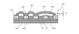
図7A及び図7Bを参照して本発明の反応プレートの断面構造の例を説明する。図7Aに示すように、反応プレート101は、底板部141とその上の主板部142を有する。反応プレート101の上には、カバー105が装着されている。底板部141と主板部142の間には、両者を貼り合わせる接着層144が設けられ、主板部142とカバー105の間には両者を貼り合わせる接着層145が設けられている。
An example of the cross-sectional structure of the reaction plate of the present invention will be described with reference to FIGS. 7A and 7B. As shown in FIG. 7A, the
底板部141と主板部142が直接接着することができる材料であれば接着層144は省略してもよい。主板部142とカバー105が直接接着することができる材料であれば接着層145は省略してもよい。
The
反応プレート101の上面には反応ウエル102が設けられている。反応ウエル102の側壁102aは、主板部142に形成された貫通孔の内面によって形成され、反応ウエル102の底は底板部141の上面によって構成されている。反応ウエル102にサンプル溶液51を収納し、その上に、オイル52を収納する。次に、主板部142の上面に蒸発防止用のカバー105を取り付ける。オイル52は、カバー105を取り付けるまでに、サンプル溶液51の蒸発防止に用いる。反応ウエル102へサンプル溶液51を収納してから、短時間でカバー105を取り付けることが可能であればオイル52は使用しなくてもよい。
A reaction well 102 is provided on the upper surface of the
底板部141、主板部142、及び、カバー105の厚さを、それぞれ、t1、t2、t3とする。また、接着層144、145の厚さを、それぞれ、t4、t5とする。サンプル溶液51及びオイル52の高さを、それぞれt6、t7とする。
The thicknesses of the
本例では、反応プレート101の上側に、蛍光を検出する検出装置23を配置する。反応ウエル102内のサンプル溶液51からの蛍光は、カバー105及び接着層145を介して行われる。そのため、カバー105及び接着層145は可視光透過可能な材料によって形成される。カバー105及び接着層145として、予め接着層が設けられた粘着ポリプロピレンシートを用いてよい。カバー105及び接着層145の厚さt3、t5は、蛍光が減衰しないようできる限り小さいことが望ましい。
In this example, a
本例では、反応プレート101を温度調節装置の上に配置する。温度調節装置からの熱は、主として反応プレート101の下面から底板部141を経由して、反応ウエル102内のサンプル溶液51に伝達される。従って、底板部141は熱伝導率が大きい材料によって形成することが望ましい。核酸分析に用いられる反応プレート101は一般にポリプロピレンなどの樹脂が用いられることが多い。しかしながら、樹脂は熱伝導率が比較的小さい。そのため、底板部141には、熱伝導率が比較的大きい金属を用いることが望ましい。更には、金属の中でも熱伝導率が高い銀、銅、金、アルミニウムなどを用いることが望ましい。また、熱損失をできるだけ回避し、加熱応答を改善するために、温度調節装置から反応ウエルまでの熱伝導経路は短いほうがよい。そのために、底板部141の厚さt1はできる限り小さい方が望ましい。
In this example, the
底板部141に金属を用いた場合、サンプルを汚染する可能性がある。その場合は、接着層144をパッシベーション層と兼ねることが可能である。例えば、シリコーン材料系の接着剤を用いることができる。この場合でも、温度調節装置から反応ウエルまでの熱伝導経路を短くするために、接着層144の厚さt4をできる限り小さくすることが望ましい。
When metal is used for the
主板部142には様々な材料を採用することが可能である。例えば、核酸分析に一般的に用いられるポリプロピレンなどの樹脂を用いることができる。温度調節装置からの熱の一部は、底板部141、接着層144及び主板部142を介して反応ウエル102内のサンプル溶液51に伝達される。この熱伝導経路も短いほうがよい。そのために、サンプル溶液51及びオイル52の高さt6、t7はできる限り小さくすることが望ましく、それに伴って主板部142の厚さt2もできる限り小さくすることが望ましい。例えば、主板部142の厚さt2は1mm以下、更に望ましくは0.5mm以下であることが望ましい。
Various materials can be used for the
また、主板部142の材料を、可視光が透過し難い材料にすれば、隣り合う反応ウエルとの光学的な干渉を遮断することが可能となる。それによって、蛍光強度測定におけるS/N比を改善させることも可能である。例えば、主板部142の材料として、黒に着色されたポリプロピレンなどの樹脂を用いることができる。
Further, if the material of the
図7Bを参照して、反応プレートが温度上昇時に示す振る舞いを説明する。反応プレート101にカバー105を取り付けるのは、通常、室温下である。反応プレート101は、PCRの温度サイクルに供されると、95℃程度に温度上昇する。従って、サンプル溶液51が気化し、反応ウエル102の内部圧力が上昇する。カバー105が十分な強度を持たない場合には、この内部圧力の上昇により、カバー105が変形する。カバー105の変形量が大きくなると、カバー105が主板部142から剥離する。すなわち、カバー105を主板部142に接着している接着層145が剥がれる。こうして、カバー105が剥離すると、反応ウエル間に連通部50が発生する。連通部50が発生すると、連通した反応ウエル間でコンタミネーションが起こり、正確な分析ができなくなる。
With reference to FIG. 7B, the behavior of the reaction plate when the temperature rises will be described. The
カバー105の変形及び剥離を防止するには、カバー105を高剛性の材料によって形成するか、又は、カバー105の厚さt3を大きくすればよい。しかしながら、それでは、反応プレート101の製造コストが上昇する。通常、核酸分析装置では、コンタミネーションを防止するために、分析に一度使用した反応プレート101は廃棄する。すなわち、反応プレート101は、通常、使い捨てである。従って、反応プレート101の製造コストの増大となる手法は得策ではない。以下に、反応プレート101の製造コストを増大させることなく、カバー105の変形及び剥離を防止する方法を説明する。
In order to prevent deformation and peeling of the
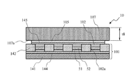
図8は、本発明による反応プレートアセンブリの構造の例を説明する。本例の反応プレートアセンブリは、反応プレート101と、その上に配置されたカバー105と、更にその上に配置された重り部材107を有する。重り部材107は、カバー105の上に着脱可能に、配置されている。即ち、カバー105と重り部材107の間には接着剤は設けられていない。重り部材107の厚さをt8とする。
FIG. 8 illustrates an example of the structure of a reaction plate assembly according to the present invention. The reaction plate assembly of this example includes a
反応プレート101は、使い捨てであってよいが、重り部材107は繰り返し使用が可能である。上述のように、本例では、反応プレート101の上側に、蛍光を検出する検出装置23を配置する。反応ウエル102内のサンプル溶液51からの蛍光は、重り部材107を介して行われる。そのため、重り部材107は、可視光透過可能な材料によって構成される。重り部材107は、反応ウエル102の内部圧力が上昇しても、変形しない、且つ、持ち上げられないことが必要である。即ち、高剛性であり、且つ、比較的比重が大きい材料が好ましい。このような材料として、石英又はガラスがある。
The
石英及びガラスは、一般に可視光の透過率が大きい。そのため、重り部材107の厚さt8は、検出装置の光学系の焦点距離などの制約は受けるものの、比較的大きくすることが可能である。即ち、重り部材107の強度及び重量を比較的大きくすることができる。従って、反応プレート101の上に重り部材107を配置することによって、温度上昇に起因して、反応ウエル102の内部圧力が上昇しても、カバー105の変形及び剥離を防止することができる。
Quartz and glass generally have high visible light transmittance. Therefore, the thickness t8 of the
本例の反応プレート101及びカバー105は、3つの互いに異なる層を積層した構造を形成する。そのため温度調節装置によって加熱されると、温度膨張係数の差に起因したバイメタル効果によって反応プレート101が歪む可能性がある。反応プレート101の上に重り部材107を配置することにより、反応プレート101の歪みを抑制し、反応プレート101と温度調節装置の密着度を向上させることができる。そのため、反応プレート101と温度調節装置の間の熱伝達率を改善させることができる。
The
PCRでは、反応プレート101は、95℃程度から60℃程度までの温度サイクルに供される。95℃で気化したサンプル溶液51が60℃程度に冷却されると、接着層145にて結露する場合がある。結露した液滴は検出装置23による蛍光強度測定の際に光の散乱をもたらし、信号強度の低下を招く。結露を防止するには、重り部材107を95〜100℃程度の温度に保持するとよい。重り部材107の温度を一定に保持する方法は、検出装置23による光学的な検出を妨げるものであってはならない。このような温度保持方法として、離れた熱源からの輻射によって重り部材107に熱を与える方法、又は、カバー105に接触する重り部材の面107aにITO(Indium Tin Oxide)などの可視光透過可能な材料を用いた温度調節装置を形成する方法がある。
In PCR, the
図9を参照して反応プレートアセンブリの構造の例を説明する。図9では、断面構造を分かりやすく表示するため、破線で示す部を除去して示している。反応プレートアセンブリは、反応プレート101と、その上の透明なカバー105と、その上の重り部材107を有する。反応プレート101は、下面側から、底板部141と主板部142を有する。底板部141と主板部142の間及び主板部142とカバー105の間にはそれぞれ薄い接着層144、145が設けられている。
An example of the structure of the reaction plate assembly will be described with reference to FIG. In FIG. 9, in order to display the cross-sectional structure in an easy-to-understand manner, the parts indicated by broken lines are removed. The reaction plate assembly includes a
反応プレート101の両端には、孔103が形成され、重り部材107の両端には、孔107bが形成されている。反応プレート101の孔103と重り部材107の孔107bが接続されて、反応プレートアセンブリの孔が形成される。反応プレートアセンブリの孔にピンを挿入し、ピンを移動させることにより、反応プレートアセンブリを移動させることができる。
反応プレート101には、複数の反応ウエル102が形成されている。反応ウエル102は、主板部142に形成された貫通孔と底板部141の上面によって形成される。反応ウエル102にはサンプル溶液51及びオイル52が装填されている。オイル52はサンプル溶液51の蒸発を防止するために用いる。全ての反応ウエル102は、半径r1の円周上に配置されている。図2で示したように、複数の反応プレート101又は反応プレートアセンブリを、温度調節装置の上に円周方向に沿って並べたとき、全ての反応ウエルが同一の円周上に配置される。したがって、回転駆動装置によって、反応プレート101又は反応プレートアセンブリを回転させたとき、全ての反応ウエルは、検出装置23の直下を通る。したがって、検出装置23を移動させることなく、すべての反応ウエルの試料を検出することができる。
A plurality of
図示の例では、カバー105の長手方向の寸法が反応プレート101の長手方向の寸法よりも短い。しかしながら、カバー105の長手方向の寸法を反応プレート101の長手方向の寸法と同一にしてもよい。その場合には、カバー105にも、孔を設ける必要がある。
In the illustrated example, the longitudinal dimension of the
図2及び図3を参照して説明した核酸分析装置では、反応プレートアセンブリを装填してもよいが、反応プレート101を装填してもよい。
In the nucleic acid analyzer described with reference to FIGS. 2 and 3, the reaction plate assembly may be loaded, but the
図2及び図3を参照して説明したように、本発明の核酸分析装置では、必要な数だけの反応プレートアセンブリ又は反応プレートを搭載し、複数の温度に設定した温度調節装置上を接触回転させることにより、PCRを行う。検出装置23の下を反応ウエル102が通過するときに、蛍光強度の測定を行う。既に測定を開始している反応プレートアセンブリ又は反応プレート101がある場合でも、温度調節装置上に空きがあれば、順次、反応プレートアセンブリ又は反応プレート101を挿入でき、測定が終了した反応プレートアセンブリ又は反応プレート101は順次、排出することができる。
As described with reference to FIGS. 2 and 3, in the nucleic acid analyzer of the present invention, as many reaction plate assemblies or reaction plates as necessary are mounted, and contact rotation is performed on temperature control devices set to a plurality of temperatures. To perform PCR. When the reaction well 102 passes under the
以上のように、本発明の反応プレート101を用いることによって、光学系を固定したままで全ての反応ウエルの蛍光強度測定が可能で、複数反応プレート101の連続ローディング/アンローディングが可能な高速PCR装置を実現することが可能となる。
As described above, by using the
以上本発明の例を説明したが本発明は上述の例に限定されるものではなく、特許請求の範囲に記載された発明の範囲にて様々な変更が可能であることは、当業者によって容易に理解されよう。 Although the examples of the present invention have been described above, the present invention is not limited to the above-described examples, and it is easy for those skilled in the art to make various modifications within the scope of the invention described in the claims. Will be understood.
10A〜10H…反応プレートアセンブリ、20A〜20H…温度調節装置、23…検出装置、50…連通部、51…サンプル溶液、52…オイル、100…円周、101…反応プレート、101a、101b、101c、101d…反応プレートの境界、101f…反応ウエルが設けられるはずの位置、101g…円周と反応プレートの交点、102…反応ウエル、102a…反応ウエルの側壁、103…孔、105…カバー、107…重り部材、107a…重り部材のカバーに接触する面、107b…重り部材の孔、141…底板部、142…主板部、144、145…接着層、d1…隣り合う反応ウエルの間隔、D…反応プレートの幅、d2…反応ウエルと反応プレート101外形境界の間隔、o…反応ウエルが形成される円弧の中心、r1…反応ウエルが形成される円弧の半径、r2、r3、r4…反応プレート101の外形境界を形成する円弧の半径、r5…反応ウエルの面取り部の半径、t1…底板部厚さ、t2…主板部厚さ、t3…カバー厚さ、t4、t5…接着層厚さ、t6…サンプル溶液高さ、t7…オイル高さ、t8…重り部材厚さ
10A to 10H ... reaction plate assembly, 20A to 20H ... temperature control device, 23 ... detection device, 50 ... communication part, 51 ... sample solution, 52 ... oil, 100 ... circumference, 101 ... reaction plate, 101a, 101b, 101c , 101d: boundary of reaction plate, 101f: position where reaction well should be provided, 101g: intersection of circumference and reaction plate, 102 ... reaction well, 102a: sidewall of reaction well, 103 ... hole, 105 ... cover, 107 ... weight member, 107a ... surface contacting weight member cover, 107b ... weight member hole, 141 ... bottom plate portion, 142 ... main plate portion, 144, 145 ... adhesive layer, d1 ... spacing between adjacent reaction wells, D ... Reaction plate width, d2 ... interval between reaction well and
Claims (19)
前記反応ウエルは所定の半径r1の円の円周に沿って円弧状に配置されていることを特徴とする反応プレート。 A laminar reaction plate having one or more reaction wells,
The reaction plate, wherein the reaction wells are arranged in an arc shape along a circumference of a circle having a predetermined radius r1.
複数の前記反応プレートを前記半径r1の円の円周に沿って並べると、前記複数の反応プレートの反応ウエルは、前記半径r1の円の円周に沿って配置されることを特徴とする反応プレート。 The reaction plate of claim 1, wherein
When a plurality of the reaction plates are arranged along the circumference of the circle having the radius r1, the reaction wells of the plurality of reaction plates are arranged along the circumference of the circle having the radius r1. plate.
複数の前記反応プレートを前記半径r1の円の円周に沿って並べると、前記複数の反応プレートの反応ウエルは、同一間隔で配置されることを特徴とする反応プレート。 The reaction plate of claim 1, wherein
A reaction plate, wherein when a plurality of the reaction plates are arranged along the circumference of the circle having the radius r1, the reaction wells of the plurality of reaction plates are arranged at the same interval.
前記反応ウエルの端部には、孔が形成され、該孔は、前記半径r1の円の円周より偏奇して配置されていることを特徴とする反応プレート。 The reaction plate of claim 1, wherein
A reaction plate, wherein a hole is formed at an end of the reaction well, and the hole is deviated from a circumference of the circle having the radius r1.
前記反応ウエルの平面形状は、前記半径r1の円の円周に沿って湾曲した長円形状であることを特徴とする反応プレート。 The reaction plate of claim 1, wherein
The reaction plate according to claim 1, wherein the planar shape of the reaction well is an oval shape curved along the circumference of the circle having the radius r1.
前記半径r1の円と同心状の2つ円の円周に沿って形成された内周縁と外周縁を有する湾曲した帯状に形成されていることを特徴とする反応プレート。 The reaction plate of claim 1, wherein
A reaction plate, wherein the reaction plate is formed in a curved belt shape having an inner peripheral edge and an outer peripheral edge formed along the circumference of two circles concentric with the circle having the radius r1.
前記反応ウエルを覆うように透明なカバーが装着されていることを特徴とする反応プート。 The reaction plate of claim 1, wherein
A reaction pouch comprising a transparent cover so as to cover the reaction well.
互いに接着された主板部と底板部とを有し、前記主板部の孔によって前記反応ウエルの側壁が形成され、前記底板部の面によって前記反応ウエルの底面が形成されることを特徴とする反応プレート。 The reaction plate of claim 1, wherein
A reaction having a main plate portion and a bottom plate portion bonded to each other, wherein a side wall of the reaction well is formed by a hole in the main plate portion, and a bottom surface of the reaction well is formed by a surface of the bottom plate portion. plate.
前記主板部は、厚さt2が1mm以下であり、可視光が透過し難い材料によって形成されていることを特徴とする反応プレート。 The reaction plate of claim 8, wherein
The reaction plate according to claim 1, wherein the main plate portion has a thickness t2 of 1 mm or less and is made of a material that hardly transmits visible light.
前記底板部は、金属によって形成されていることを特徴とする反応プレート。 The reaction plate of claim 8, wherein
The reaction plate, wherein the bottom plate portion is made of metal.
前記反応ウエルは所定の半径r1の円の円周に沿って円弧状に配置されていることを特徴とする反応プレートアセンブリ。 A reaction plate having one or more reaction wells; a visible light transmissive cover attached to the reaction plate so as to cover the reaction well; and a visible light transmissive weight member attached so as to cover the cover. And having
The reaction plate assembly, wherein the reaction wells are arranged in an arc shape along a circumference of a circle having a predetermined radius r1.
複数の前記反応プレートアセンブリを前記半径r1の円の円周に沿って並べると、前記複数の反応プレートの反応ウエルは、前記半径r1の円の円周に沿って配置されることを特徴とする反応プレートアセンブリ。 The reaction plate assembly of claim 11, wherein
When a plurality of the reaction plate assemblies are arranged along the circumference of the circle having the radius r1, the reaction wells of the plurality of reaction plates are arranged along the circumference of the circle having the radius r1. Reaction plate assembly.
複数の前記反応プレートアセンブリを前記半径r1の円の円周に沿って並べると、前記複数の反応プレートの反応ウエルは、同一間隔で配置されることを特徴とする反応プレートアセンブリ。 The reaction plate assembly of claim 11, wherein
When the plurality of reaction plate assemblies are arranged along the circumference of the circle having the radius r1, the reaction wells of the plurality of reaction plates are arranged at the same interval.
前記反応プレート及び前記重り部材は、前記半径r1の円と同心状の2つ円の円周に沿って形成された内周縁と外周縁を有する湾曲した帯状に形成されていることを特徴とする反応プレートアセンブリ。 The reaction plate assembly of claim 11, wherein
The reaction plate and the weight member are formed in a curved belt shape having an inner peripheral edge and an outer peripheral edge formed along the circumference of two circles concentric with the circle of the radius r1. Reaction plate assembly.
前記反応プレートアセンブリは、一つ以上の反応ウエルを有する反応プレートと、前記反応ウエルを覆うように前記反応プレートに装着された可視光透過可能なカバーと、該カバーを覆うように装着された可視光透過可能な重り部材と、を有し、
前記反応ウエルは前記半径r1の円の円周に沿って円弧状に配置されており、
複数の前記反応プレートアセンブリを前記温度調節装置の上にて前記半径r1の円の円周に沿って並べると、前記複数の反応プレートの反応ウエルは、前記半径r1の円の円周に沿って配置されることを特徴とする核酸分析装置。 A plurality of temperature adjusting devices arranged along a circumferential direction of a circle having a predetermined radius r1, a rotating mechanism for rotating a reaction plate assembly arranged on the temperature adjusting device along the circumferential direction, and a reaction A nucleic acid analyzer having a detection device for optically detecting a sample loaded in a plate assembly;
The reaction plate assembly includes a reaction plate having one or more reaction wells, a visible light transmissive cover attached to the reaction plate so as to cover the reaction well, and a visible light attached so as to cover the cover. A weight member capable of transmitting light,
The reaction well is arranged in an arc along the circumference of the circle with the radius r1,
When a plurality of the reaction plate assemblies are arranged on the temperature control device along the circumference of the circle having the radius r1, the reaction wells of the plurality of reaction plates are arranged along the circumference of the circle having the radius r1. A nucleic acid analyzer characterized by being arranged.
前記反応プレートは、互いに接着された主板部と底板部とを有し、前記主板部の孔によって前記反応ウエルの側壁が形成され、前記底板部の面によって前記反応ウエルの底面が形成されることを特徴とする核酸分析装置。 The nucleic acid analyzer according to claim 15,
The reaction plate has a main plate portion and a bottom plate portion bonded to each other, a side wall of the reaction well is formed by a hole in the main plate portion, and a bottom surface of the reaction well is formed by a surface of the bottom plate portion. A nucleic acid analyzer characterized by the above.
複数の前記反応プレートアセンブリを前記温度調節装置の上にて前記半径r1の円の円周に沿って並べると、前記複数の反応プレートの反応ウエルは、同一間隔で配置されることを特徴とする核酸分析装置。 The nucleic acid analyzer according to claim 15,
When the plurality of reaction plate assemblies are arranged on the temperature control device along the circumference of the circle having the radius r1, the reaction wells of the plurality of reaction plates are arranged at the same interval. Nucleic acid analyzer.
前記反応ウエルの平面形状は、前記半径r1の円の円周に沿って湾曲した長円形状であることを特徴とする核酸分析装置。 The nucleic acid analyzer according to claim 15,
The nucleic acid analyzer according to claim 1, wherein the planar shape of the reaction well is an oval shape curved along the circumference of the circle having the radius r1.
前記複数の温度調節装置は、独立に所定の温度サイクルに従って温度調節することができるように構成されており、それによってPCR(ポリメラーゼ連鎖反応)を行うことができることを特徴とする核酸分析装置。 The nucleic acid analyzer according to claim 15,
The nucleic acid analyzer, wherein the plurality of temperature control devices are configured to be independently temperature-controllable according to a predetermined temperature cycle, whereby PCR (polymerase chain reaction) can be performed.
Priority Applications (5)
| Application Number | Priority Date | Filing Date | Title |
|---|---|---|---|
| JP2010249275A JP2012103019A (en) | 2010-11-08 | 2010-11-08 | Reaction plate assembly, reaction plate, and nucleic acid analyzer |
| CN201180053742.5A CN103201633B (en) | 2010-11-08 | 2011-10-27 | Reaction plate assembly, reaction plate and nucleic acid analysis device |
| US13/883,830 US9221055B2 (en) | 2010-11-08 | 2011-10-27 | Reaction plate assembly, reaction plate and nucleic acid analysis device |
| PCT/JP2011/074767 WO2012063647A1 (en) | 2010-11-08 | 2011-10-27 | Reaction plate assembly, reaction plate and nucleic acid analysis device |
| EP11840550.5A EP2639587B1 (en) | 2010-11-08 | 2011-10-27 | Reaction plate assembly, reaction plate and nucleic acid analysis device |
Applications Claiming Priority (1)
| Application Number | Priority Date | Filing Date | Title |
|---|---|---|---|
| JP2010249275A JP2012103019A (en) | 2010-11-08 | 2010-11-08 | Reaction plate assembly, reaction plate, and nucleic acid analyzer |
Publications (1)
| Publication Number | Publication Date |
|---|---|
| JP2012103019A true JP2012103019A (en) | 2012-05-31 |
Family
ID=46393612
Family Applications (1)
| Application Number | Title | Priority Date | Filing Date |
|---|---|---|---|
| JP2010249275A Pending JP2012103019A (en) | 2010-11-08 | 2010-11-08 | Reaction plate assembly, reaction plate, and nucleic acid analyzer |
Country Status (1)
| Country | Link |
|---|---|
| JP (1) | JP2012103019A (en) |
Cited By (1)
| Publication number | Priority date | Publication date | Assignee | Title |
|---|---|---|---|---|
| WO2018159055A1 (en) * | 2017-02-28 | 2018-09-07 | 信越ポリマー株式会社 | Fluorescence assay multi-well plate and multi-well plate set, and method for producing fluorescence assay multi-well plate |
Citations (10)
| Publication number | Priority date | Publication date | Assignee | Title |
|---|---|---|---|---|
| JPS61274267A (en) * | 1985-05-30 | 1986-12-04 | Toshiba Corp | Automatic chemical analyzer |
| JPH11326339A (en) * | 1998-05-08 | 1999-11-26 | Wako Pure Chem Ind Ltd | Testing instrument for use in diagnosis automatic analyzing apparatus |
| JP2004500233A (en) * | 1999-10-22 | 2004-01-08 | アクララ バイオサイエンシーズ, インコーポレイテッド | Sealing for microfluidic devices |
| JP2004212359A (en) * | 2003-01-09 | 2004-07-29 | Fuji Electric Systems Co Ltd | Manufacturing method for micro-well plate |
| JP2004536291A (en) * | 2001-04-18 | 2004-12-02 | スリーエム イノベイティブ プロパティズ カンパニー | Multi-format sample processing device, method and system |
| JP2005304445A (en) * | 2004-04-26 | 2005-11-04 | Canon Inc | Pcr amplification reaction device and pcr amplification reaction method using the same |
| JP2007316064A (en) * | 2006-05-12 | 2007-12-06 | F Hoffmann La Roche Ag | Multi-well plate |
| WO2008146754A1 (en) * | 2007-05-23 | 2008-12-04 | Trust Co., Ltd. | Container for liquid reaction mixture, reaction-promoting device using the same and method therefor |
| KR20100008476A (en) * | 2008-07-16 | 2010-01-26 | 연세대학교 산학협력단 | Pcr device which has a real-time monitoring fuction and method of real-time monitoring the same |
| JP2010519892A (en) * | 2007-03-02 | 2010-06-10 | コーベット リサーチ プロプライエタリー リミテッド | Apparatus and method for nucleic acid amplification |
-
2010
- 2010-11-08 JP JP2010249275A patent/JP2012103019A/en active Pending
Patent Citations (10)
| Publication number | Priority date | Publication date | Assignee | Title |
|---|---|---|---|---|
| JPS61274267A (en) * | 1985-05-30 | 1986-12-04 | Toshiba Corp | Automatic chemical analyzer |
| JPH11326339A (en) * | 1998-05-08 | 1999-11-26 | Wako Pure Chem Ind Ltd | Testing instrument for use in diagnosis automatic analyzing apparatus |
| JP2004500233A (en) * | 1999-10-22 | 2004-01-08 | アクララ バイオサイエンシーズ, インコーポレイテッド | Sealing for microfluidic devices |
| JP2004536291A (en) * | 2001-04-18 | 2004-12-02 | スリーエム イノベイティブ プロパティズ カンパニー | Multi-format sample processing device, method and system |
| JP2004212359A (en) * | 2003-01-09 | 2004-07-29 | Fuji Electric Systems Co Ltd | Manufacturing method for micro-well plate |
| JP2005304445A (en) * | 2004-04-26 | 2005-11-04 | Canon Inc | Pcr amplification reaction device and pcr amplification reaction method using the same |
| JP2007316064A (en) * | 2006-05-12 | 2007-12-06 | F Hoffmann La Roche Ag | Multi-well plate |
| JP2010519892A (en) * | 2007-03-02 | 2010-06-10 | コーベット リサーチ プロプライエタリー リミテッド | Apparatus and method for nucleic acid amplification |
| WO2008146754A1 (en) * | 2007-05-23 | 2008-12-04 | Trust Co., Ltd. | Container for liquid reaction mixture, reaction-promoting device using the same and method therefor |
| KR20100008476A (en) * | 2008-07-16 | 2010-01-26 | 연세대학교 산학협력단 | Pcr device which has a real-time monitoring fuction and method of real-time monitoring the same |
Cited By (1)
| Publication number | Priority date | Publication date | Assignee | Title |
|---|---|---|---|---|
| WO2018159055A1 (en) * | 2017-02-28 | 2018-09-07 | 信越ポリマー株式会社 | Fluorescence assay multi-well plate and multi-well plate set, and method for producing fluorescence assay multi-well plate |
Similar Documents
| Publication | Publication Date | Title |
|---|---|---|
| WO2012063647A1 (en) | Reaction plate assembly, reaction plate and nucleic acid analysis device | |
| KR102266347B1 (en) | Design of paper sensor | |
| EP0834729A2 (en) | DNA microwell device and method | |
| JP2009509144A (en) | Thermal cycler for microfluidic array assays | |
| US20070211245A1 (en) | Reference microplates and methods for making and using the reference microplates | |
| US20220212190A1 (en) | Microfluidic cartridges for enhanced amplification of polynucleotide-containing samples | |
| US9593367B2 (en) | Genetic test system | |
| US20110142092A1 (en) | Screening system and method for analyzing a plurality of biosensors | |
| JP2012118055A (en) | Reaction treatment apparatus and reaction treatment method | |
| Gomez | Paper microfluidics in bioanalysis | |
| EP2332654B1 (en) | System and method for cycling liquid samples through a series of temperature excursions | |
| KR101513273B1 (en) | A rotary type PCR machine and a PCR chip | |
| EP2629892B1 (en) | Device having rfid tag and fluidics element | |
| JP6128733B2 (en) | Luminescence detection device and manufacturing method thereof | |
| JP2012103019A (en) | Reaction plate assembly, reaction plate, and nucleic acid analyzer | |
| WO2004024330A2 (en) | Thermocycler and sample holder | |
| US20150029491A1 (en) | Apparatus for microfluid detection | |
| EP3599023B1 (en) | A method to monitor and control the temperature of a sample holder of a laboratory instrument | |
| JP2013000012A (en) | Reaction device, and reactor using the same | |
| JP5426476B2 (en) | Analysis tool and micro analysis system | |
| JP2014079194A (en) | Reaction vessel and nucleic acid analysis apparatus using the same | |
| US20210283614A1 (en) | Heater For Apparatus For Detecting Molecule(s) | |
| KR102494445B1 (en) | Volume dispenser and method using the same | |
| US20190145900A1 (en) | System for Implementing Paper Diagnostic Testing | |
| US20180059004A1 (en) | Analysis system with spacing means |
Legal Events
| Date | Code | Title | Description |
|---|---|---|---|
| A621 | Written request for application examination |
Free format text: JAPANESE INTERMEDIATE CODE: A621 Effective date: 20130205 |
|
| A131 | Notification of reasons for refusal |
Free format text: JAPANESE INTERMEDIATE CODE: A131 Effective date: 20140507 |
|
| A02 | Decision of refusal |
Free format text: JAPANESE INTERMEDIATE CODE: A02 Effective date: 20141007 |