JP2012087936A - Valve for controlling high pressure air pulse - Google Patents
Valve for controlling high pressure air pulse Download PDFInfo
- Publication number
- JP2012087936A JP2012087936A JP2011258595A JP2011258595A JP2012087936A JP 2012087936 A JP2012087936 A JP 2012087936A JP 2011258595 A JP2011258595 A JP 2011258595A JP 2011258595 A JP2011258595 A JP 2011258595A JP 2012087936 A JP2012087936 A JP 2012087936A
- Authority
- JP
- Japan
- Prior art keywords
- valve
- tank
- high pressure
- closing member
- valve closing
- Prior art date
- Legal status (The legal status is an assumption and is not a legal conclusion. Google has not performed a legal analysis and makes no representation as to the accuracy of the status listed.)
- Pending
Links
- 238000007789 sealing Methods 0.000 claims abstract description 14
- 230000002093 peripheral effect Effects 0.000 claims abstract description 7
- 239000000428 dust Substances 0.000 abstract 2
- 238000004140 cleaning Methods 0.000 description 7
- 239000000463 material Substances 0.000 description 5
- 230000006835 compression Effects 0.000 description 3
- 238000007906 compression Methods 0.000 description 3
- 239000004033 plastic Substances 0.000 description 3
- 239000012530 fluid Substances 0.000 description 2
- 238000012423 maintenance Methods 0.000 description 2
- 239000004677 Nylon Substances 0.000 description 1
- 238000005553 drilling Methods 0.000 description 1
- 239000013536 elastomeric material Substances 0.000 description 1
- 238000002347 injection Methods 0.000 description 1
- 239000007924 injection Substances 0.000 description 1
- NJPPVKZQTLUDBO-UHFFFAOYSA-N novaluron Chemical compound C1=C(Cl)C(OC(F)(F)C(OC(F)(F)F)F)=CC=C1NC(=O)NC(=O)C1=C(F)C=CC=C1F NJPPVKZQTLUDBO-UHFFFAOYSA-N 0.000 description 1
- 229920001778 nylon Polymers 0.000 description 1
- 239000000565 sealant Substances 0.000 description 1
- 239000003566 sealing material Substances 0.000 description 1
- 238000011144 upstream manufacturing Methods 0.000 description 1
- 239000002699 waste material Substances 0.000 description 1
Images



Classifications
-
- F—MECHANICAL ENGINEERING; LIGHTING; HEATING; WEAPONS; BLASTING
- F16—ENGINEERING ELEMENTS AND UNITS; GENERAL MEASURES FOR PRODUCING AND MAINTAINING EFFECTIVE FUNCTIONING OF MACHINES OR INSTALLATIONS; THERMAL INSULATION IN GENERAL
- F16K—VALVES; TAPS; COCKS; ACTUATING-FLOATS; DEVICES FOR VENTING OR AERATING
- F16K1/00—Lift valves or globe valves, i.e. cut-off apparatus with closure members having at least a component of their opening and closing motion perpendicular to the closing faces
- F16K1/30—Lift valves or globe valves, i.e. cut-off apparatus with closure members having at least a component of their opening and closing motion perpendicular to the closing faces specially adapted for pressure containers
- F16K1/301—Lift valves or globe valves, i.e. cut-off apparatus with closure members having at least a component of their opening and closing motion perpendicular to the closing faces specially adapted for pressure containers only shut-off valves, i.e. valves without additional means
- F16K1/302—Lift valves or globe valves, i.e. cut-off apparatus with closure members having at least a component of their opening and closing motion perpendicular to the closing faces specially adapted for pressure containers only shut-off valves, i.e. valves without additional means with valve member and actuator on the same side of the seat
-
- F—MECHANICAL ENGINEERING; LIGHTING; HEATING; WEAPONS; BLASTING
- F16—ENGINEERING ELEMENTS AND UNITS; GENERAL MEASURES FOR PRODUCING AND MAINTAINING EFFECTIVE FUNCTIONING OF MACHINES OR INSTALLATIONS; THERMAL INSULATION IN GENERAL
- F16K—VALVES; TAPS; COCKS; ACTUATING-FLOATS; DEVICES FOR VENTING OR AERATING
- F16K27/00—Construction of housing; Use of materials therefor
-
- F—MECHANICAL ENGINEERING; LIGHTING; HEATING; WEAPONS; BLASTING
- F16—ENGINEERING ELEMENTS AND UNITS; GENERAL MEASURES FOR PRODUCING AND MAINTAINING EFFECTIVE FUNCTIONING OF MACHINES OR INSTALLATIONS; THERMAL INSULATION IN GENERAL
- F16K—VALVES; TAPS; COCKS; ACTUATING-FLOATS; DEVICES FOR VENTING OR AERATING
- F16K15/00—Check valves
- F16K15/02—Check valves with guided rigid valve members
- F16K15/025—Check valves with guided rigid valve members the valve being loaded by a spring
- F16K15/026—Check valves with guided rigid valve members the valve being loaded by a spring the valve member being a movable body around which the medium flows when the valve is open
- F16K15/028—Check valves with guided rigid valve members the valve being loaded by a spring the valve member being a movable body around which the medium flows when the valve is open the valve member consisting only of a predominantly disc-shaped flat element
-
- F—MECHANICAL ENGINEERING; LIGHTING; HEATING; WEAPONS; BLASTING
- F16—ENGINEERING ELEMENTS AND UNITS; GENERAL MEASURES FOR PRODUCING AND MAINTAINING EFFECTIVE FUNCTIONING OF MACHINES OR INSTALLATIONS; THERMAL INSULATION IN GENERAL
- F16K—VALVES; TAPS; COCKS; ACTUATING-FLOATS; DEVICES FOR VENTING OR AERATING
- F16K27/00—Construction of housing; Use of materials therefor
- F16K27/02—Construction of housing; Use of materials therefor of lift valves
- F16K27/0209—Check valves or pivoted valves
-
- F—MECHANICAL ENGINEERING; LIGHTING; HEATING; WEAPONS; BLASTING
- F17—STORING OR DISTRIBUTING GASES OR LIQUIDS
- F17C—VESSELS FOR CONTAINING OR STORING COMPRESSED, LIQUEFIED OR SOLIDIFIED GASES; FIXED-CAPACITY GAS-HOLDERS; FILLING VESSELS WITH, OR DISCHARGING FROM VESSELS, COMPRESSED, LIQUEFIED, OR SOLIDIFIED GASES
- F17C13/00—Details of vessels or of the filling or discharging of vessels
- F17C13/04—Arrangement or mounting of valves
-
- Y—GENERAL TAGGING OF NEW TECHNOLOGICAL DEVELOPMENTS; GENERAL TAGGING OF CROSS-SECTIONAL TECHNOLOGIES SPANNING OVER SEVERAL SECTIONS OF THE IPC; TECHNICAL SUBJECTS COVERED BY FORMER USPC CROSS-REFERENCE ART COLLECTIONS [XRACs] AND DIGESTS
- Y10—TECHNICAL SUBJECTS COVERED BY FORMER USPC
- Y10T—TECHNICAL SUBJECTS COVERED BY FORMER US CLASSIFICATION
- Y10T137/00—Fluid handling
- Y10T137/598—With repair, tapping, assembly, or disassembly means
- Y10T137/6065—Assembling or disassembling reciprocating valve
-
- Y—GENERAL TAGGING OF NEW TECHNOLOGICAL DEVELOPMENTS; GENERAL TAGGING OF CROSS-SECTIONAL TECHNOLOGIES SPANNING OVER SEVERAL SECTIONS OF THE IPC; TECHNICAL SUBJECTS COVERED BY FORMER USPC CROSS-REFERENCE ART COLLECTIONS [XRACs] AND DIGESTS
- Y10—TECHNICAL SUBJECTS COVERED BY FORMER USPC
- Y10T—TECHNICAL SUBJECTS COVERED BY FORMER US CLASSIFICATION
- Y10T137/00—Fluid handling
- Y10T137/7504—Removable valve head and seat unit
-
- Y—GENERAL TAGGING OF NEW TECHNOLOGICAL DEVELOPMENTS; GENERAL TAGGING OF CROSS-SECTIONAL TECHNOLOGIES SPANNING OVER SEVERAL SECTIONS OF THE IPC; TECHNICAL SUBJECTS COVERED BY FORMER USPC CROSS-REFERENCE ART COLLECTIONS [XRACs] AND DIGESTS
- Y10—TECHNICAL SUBJECTS COVERED BY FORMER USPC
- Y10T—TECHNICAL SUBJECTS COVERED BY FORMER US CLASSIFICATION
- Y10T137/00—Fluid handling
- Y10T137/7722—Line condition change responsive valves
- Y10T137/7771—Bi-directional flow valves
-
- Y—GENERAL TAGGING OF NEW TECHNOLOGICAL DEVELOPMENTS; GENERAL TAGGING OF CROSS-SECTIONAL TECHNOLOGIES SPANNING OVER SEVERAL SECTIONS OF THE IPC; TECHNICAL SUBJECTS COVERED BY FORMER USPC CROSS-REFERENCE ART COLLECTIONS [XRACs] AND DIGESTS
- Y10—TECHNICAL SUBJECTS COVERED BY FORMER USPC
- Y10T—TECHNICAL SUBJECTS COVERED BY FORMER US CLASSIFICATION
- Y10T137/00—Fluid handling
- Y10T137/7722—Line condition change responsive valves
- Y10T137/7837—Direct response valves [i.e., check valve type]
-
- Y—GENERAL TAGGING OF NEW TECHNOLOGICAL DEVELOPMENTS; GENERAL TAGGING OF CROSS-SECTIONAL TECHNOLOGIES SPANNING OVER SEVERAL SECTIONS OF THE IPC; TECHNICAL SUBJECTS COVERED BY FORMER USPC CROSS-REFERENCE ART COLLECTIONS [XRACs] AND DIGESTS
- Y10—TECHNICAL SUBJECTS COVERED BY FORMER USPC
- Y10T—TECHNICAL SUBJECTS COVERED BY FORMER US CLASSIFICATION
- Y10T137/00—Fluid handling
- Y10T137/8593—Systems
- Y10T137/86348—Tank with internally extending flow guide, pipe or conduit
- Y10T137/86372—Inlet internally extending
Landscapes
- Engineering & Computer Science (AREA)
- General Engineering & Computer Science (AREA)
- Mechanical Engineering (AREA)
- Lift Valve (AREA)
- Filling Or Discharging Of Gas Storage Vessels (AREA)
- Fluid-Driven Valves (AREA)
- Valve Housings (AREA)
- Fluid-Pressure Circuits (AREA)
Abstract
Description
本発明は、例えば反転パルスのフィルタ清掃システムに採り入れられることがある、高圧空気パルスを制御するための弁に関する。 The present invention relates to a valve for controlling high-pressure air pulses, which may be employed, for example, in a reverse pulse filter cleaning system.
反転パルスのフィルタ清掃システムがよく知られており、様々なシステムが、特定の用途に対する様々な程度の清掃効率を提供する、特定の属性を有する制御弁を有する。
一般的に、空気パルスを制御する弁が速く開くことができ、フィルタに衝突する高圧空気パルスが比較的シャープなピークを持つ圧力波を画成し、最も効果的な清掃または微粒子を除去する力をもたらすために、弁の中を通る妨げのない流路を有すべきであることが望ましい。
Inverted pulse filter cleaning systems are well known, and various systems have control valves with specific attributes that provide varying degrees of cleaning efficiency for specific applications.
In general, the valve that controls the air pulse can open quickly, and the high-pressure air pulse impinging on the filter defines a pressure wave with a relatively sharp peak, and the most effective cleaning or removal of particulates It should be desirable to have an unobstructed flow path through the valve.
弁の開閉が速いと、システムの効率が改善される。閉じるのが遅い弁は、例えば、高圧空気を浪費する傾向があり、清掃システムの運転コストを上昇させる。同様に、開くのが遅い弁は、いくらか消散したピーク時のパルスを生み出す傾向があり、フィルタを清掃する際の効果が低下する。 Faster valve opening and closing improves system efficiency. Slowly closing valves, for example, tend to waste high pressure air, increasing the operating cost of the cleaning system. Similarly, slow-open valves tend to produce some dissipated peak pulses, reducing the effectiveness of cleaning the filter.
フィルタ清掃動作に使用される弁は、時々修理またはメンテナンスを必要とする。また、典型的な用途では、嵌める必要がある多数の弁があり、したがって、弁を嵌め、かつメンテナンスのために取り外し交換することができる速度は、比較的重要である。したがって、どのような取付け配置(mounting arrangement)が使用されても、選択された特定の取付け配置によって弁の効率を損なうべきではないが、取付け配置は、好ましくは、採り入れるのに比較的直線的であるべきである。 Valves used for filter cleaning operations sometimes require repair or maintenance. Also, in typical applications, there are a large number of valves that need to be fitted, so the speed at which the valves can be fitted and removed and replaced for maintenance is relatively important. Thus, no matter what mounting arrangement is used, the particular mounting arrangement chosen should not compromise the efficiency of the valve, but the mounting arrangement is preferably relatively linear to adopt. Should be.
典型的には、反転パルスを提供するために使用される高圧空気は、個々の弁が取り付けられる導管またはタンクに運搬または供給される。タンクは、通常は、空気量が不十分なことによってパルスの効率を低下させることなしに、個々の弁が、必要とされるように連続して動作することが可能になるのに十分な容量のものである。したがって、ほとんどのシステムでは、容量が比較的大きいタンクが採り入れられ、個々の弁がタンクに取り付けられ、各弁が清掃するフィルタエレメントの上方に位置する。圧縮空気を安全に収容するためには、このようなタンクは、典型的には円筒形の構成であり、したがって、タンク上の個々の弁の取付け配置を難しくする湾曲した壁面に個々の弁を取り付ける必要がある。あるいは、弁を、フィルタの列全体を清掃することができるように提供することができ、フィルタは、典型的には一連の穴を有する形状の送風管の下方につるされ、各穴は清掃のための空気を各フィルタに分配するようにフィルタエレメントに対応する。 Typically, the high pressure air used to provide the reversal pulse is conveyed or supplied to a conduit or tank to which individual valves are attached. The tank is usually of sufficient capacity to allow individual valves to operate continuously as needed without reducing the efficiency of the pulse due to insufficient air volume. belongs to. Thus, in most systems, relatively large tanks are taken, individual valves are attached to the tank, and each valve is located above the filter element to be cleaned. In order to safely accommodate compressed air, such tanks typically have a cylindrical configuration, and therefore individual valves on curved walls that make it difficult to place individual valves on the tank. It is necessary to install. Alternatively, a valve can be provided so that the entire row of filters can be cleaned, with the filter typically suspended below a blow tube shaped with a series of holes, each hole being cleaned. Corresponding to the filter elements so as to distribute the air to the respective filters.
本明細書の第1の態様によれば、圧力タンクからの圧縮空気の制御の際に使用するための弁であって、圧力タンクが、出口が形成される壁面を含み、壁面が、内面および外面を有し、使用時に圧力タンクの内部に配置される内側端部と、使用時にタンクの外部に配置される外側端部とを有する、全体的に円筒形の構成の弁体と、弁体中を延びる流路であって、本体の内側端部においてまたはその隣に入口を有し、本体の外側端部においてまたはその隣に出口を有する流路と、流路を囲む弁座と、弁を開き、また閉じるように、それぞ
れ弁座に向かって、またそこから離れるように移動可能である弁閉止部材(valve closure member)と、弁を作動させるために弁閉止部材を移動させるための作動手段とを備え、弁体が、その内側端部においてまたはその隣に少なくとも1つの横方向に延びる取付け構造(mounting formation)を有し、取付け構造が、内側端部および取付け構造が圧力タンクに出口を通って差し込まれることを可能にするように成形され寸法設定され、適位置にあるときには、取付け構造が、出口の隣のタンクの壁面の内面と係合することを特徴とし、開口部に隣接する壁面の外面と係合するように、取付け構造に向けて移動可能である取付けカラーを含み、それにより、取付け構造と取付けカラーの間でタンク壁面を締め付ける弁が提供される。
According to a first aspect of the present specification, a valve for use in controlling compressed air from a pressure tank, wherein the pressure tank includes a wall surface on which an outlet is formed, the wall surface comprising an inner surface and A valve body having a generally cylindrical configuration, having an outer surface and having an inner end disposed inside the pressure tank in use and an outer end disposed outside the tank in use; A flow path extending therethrough, having an inlet at or next to the inner end of the body, and having an outlet at or next to the outer end of the body, a valve seat surrounding the flow path, and a valve A valve closure member that is movable toward and away from the valve seat to open and close, and an action to move the valve closing member to actuate the valve Means, and the valve body is Having at least one laterally extending mounting structure at or adjacent to the inner end, the mounting structure allowing the inner end and the mounting structure to be plugged into the pressure tank through the outlet When shaped and dimensioned and in position, the mounting structure is characterized by engaging the inner surface of the wall surface of the tank next to the outlet and engaging the outer surface of the wall surface adjacent to the opening. Including a mounting collar that is movable toward the mounting structure, thereby providing a valve that clamps the tank wall between the mounting structure and the mounting collar.
横方向に延びる取付け構造が、好ましくは、弁体の両側に1対の横方向に延びるフランジを含む。好ましくは、フランジは、壁面の内面に載るように輪郭付けされた下面を有する。 The laterally extending mounting structure preferably includes a pair of laterally extending flanges on either side of the valve body. Preferably, the flange has a lower surface contoured to rest on the inner surface of the wall surface.
弁座は、弁体の内側端部に隣接して配置することができ、弁閉止部材は、弁がタンクに動作可能に取り付けられるときに圧力タンクの内部に配置される。
好ましくは、取付けカラーは、出口の周りに封止を形成するための封止手段を含む。取付けカラーは、壁面の外面に載る封止面を有することができる。封止面は、環状の封止リングが配置された環状の溝をその中に有することができる。カラーは、その径方向内側面に封止リングを有することができ、その封止リングは、弁体の径方向外面と共に封止を形成する。取付けカラーは、好ましくは、弁体に形成されるねじ山とねじ係合しているユニオンナットによって移動可能である。
The valve seat can be disposed adjacent to the inner end of the valve body, and the valve closure member is disposed within the pressure tank when the valve is operably attached to the tank.
Preferably, the mounting collar includes a sealing means for forming a seal around the outlet. The mounting collar can have a sealing surface that rests on the outer surface of the wall surface. The sealing surface can have therein an annular groove in which an annular sealing ring is arranged. The collar can have a sealing ring on its radially inner surface, which seal forms a seal with the radially outer surface of the valve body. The mounting collar is preferably movable by a union nut that is threadedly engaged with a thread formed in the valve body.
本発明の第2の態様によれば、圧力タンクからの圧縮空気の制御の際に使用するための弁であって、圧力タンクが、出口が形成される壁面を含み、壁面が、内面および外面を有し、使用時に圧力タンクの内部に配置される内側端部と、使用時にタンクの外部に配置される外側端部とを画定する、全体的に円筒形の構成の弁体と、弁体中を延びる流路であって、本体の内側端部においてまたはその隣に入口を有し、本体の外側端部においてまたはその隣に出口を有する流路と、流路を囲む弁座と、弁を開き、また閉じるように、それぞれ弁座に向かって、またそこから離れるように移動可能である弁閉止部材と、弁を作動させるために弁閉止部材を移動させるための作動手段とを備え、弁体が、弁体の内側端部と同軸にそれに取り付けられるか、またはその上に形成されたシリンダを有し、弁閉止部材が、弁座に向けて、またそれから離れるようにシリンダ内で摺動式であるピストンの形態であり、ピストンが、弁を閉じるために弁座と係合するように適合されることを特徴とする弁が提供される。 According to the second aspect of the present invention, there is provided a valve for use in controlling compressed air from a pressure tank, wherein the pressure tank includes a wall surface on which an outlet is formed, and the wall surface includes an inner surface and an outer surface. A valve body having a generally cylindrical configuration and defining an inner end disposed inside the pressure tank in use and an outer end disposed outside the tank in use; A flow path extending therethrough, having an inlet at or next to the inner end of the body, and having an outlet at or next to the outer end of the body, a valve seat surrounding the flow path, and a valve A valve closing member that is movable toward and away from the valve seat to open and close, and an actuating means for moving the valve closing member to actuate the valve, Whether the disc is mounted coaxially with the inner end of the disc Or in the form of a piston having a cylinder formed thereon, the valve closing member being slidable in the cylinder towards and away from the valve seat, the piston for closing the valve A valve is provided that is adapted to engage a valve seat.
好ましくは、シリンダは、シリンダを弁座と同軸に整列して保持する、複数のシリンダ支持アームによって弁体に連結され、アームの間の隙間は、流路に入口を画定する。
作動手段は、好ましくは、シリンダを空気に通気するか、またはピストンが弁座に対して移動するように高圧流体源を提供するように適合されたパイロット弁を備える。シリンダは、好ましくは、前記シリンダ支持アームの1つに沿って通るパイロット弁通路を介してパイロット弁に連結される。
Preferably, the cylinder is connected to the valve body by a plurality of cylinder support arms that hold the cylinder in coaxial alignment with the valve seat, and the gap between the arms defines an inlet in the flow path.
The actuation means preferably comprises a pilot valve adapted to vent the cylinder to air or to provide a source of high pressure fluid so that the piston moves relative to the valve seat. The cylinder is preferably connected to the pilot valve via a pilot valve passage that runs along one of the cylinder support arms.
本発明のさらなる特徴は、ピストンディスクおよび弁閉止ディスク備え、使用時に弁の弁座と共に封止するように適合された弁閉止部材であって、2枚のディスクが、スピンドルによって一緒に同軸に保持され、ピストンディスクが、周囲縁部の周りを延びる封止リングを有し、弁閉止ディスクが、その周囲縁部に、使用時に弁閉止ディスクを弁座と位置合わせして維持するのを助ける案内面を有する弁閉止部材を提供する。 A further feature of the present invention is a valve closing member comprising a piston disc and a valve closing disc adapted to seal with the valve seat in use, the two discs being held together coaxially by a spindle The piston disk has a sealing ring extending around the peripheral edge, and the valve closing disk guides at its peripheral edge to help maintain the valve closing disk in alignment with the valve seat during use. A valve closure member having a surface is provided.
本発明のこれらのおよびさらなる特徴は、例示によって以下に与えられる本発明の実施
形態の説明から明らかにされるであろう。説明の際に、添付の図面を参照するが、図面に示された特定の特徴を、本発明に対する限定として解釈すべきではない。
These and further features of the present invention will become apparent from the description of embodiments of the invention given below by way of illustration. In the description, reference is made to the accompanying drawings, which should not be construed as limiting the particular features illustrated in the drawings.
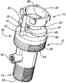
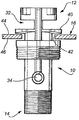
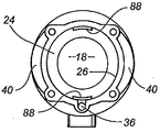
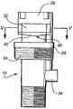
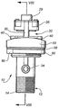
最初に図1から図5を参照すると、弁体10は、単体の注入成形品として形成され、内側端部12および外側端部14を有する全体的に円筒形の構成である。内側端部12は、図2に16で概略的に示された圧力タンク内に全体的に取り付けられ、内側端部12はタンクの内側、外側端部14はタンクの外側にある。流路18が弁体中を通って延び、流路18は、入口20および出口22を有する。弁座24が流路18を囲み、以下により詳細に説明するように、ピストンタイプの弁閉止部材によって開閉される。
Referring initially to FIGS. 1-5, the
シリンダ26が、弁体の内側端部に位置し、以下に詳細に説明するピストンタイプの弁閉止部材28を摺動式に含む。シリンダ26は、図面の図7および図8に最も明確に示すように、着脱可能な端部壁面29を備える。シリンダ26は、1対のシリンダ支持アーム30によって弁体の受け台に連結される。支持アームの間の隙間32は、弁が開いているときに高圧空気がその中を通って流路18に入る、流路18への入口を提供する。
A
弁は、パイロット弁口34に直接または間接的に連結されたパイロット弁(図示せず)によって開閉される。図面の図8に明確に示すように、パイロット弁口34は、パイロット弁の流路36に連結され、弁閉止部材を作動させるためにシリンダ26の内部に連結される。これらの態様を以下でより詳細に考察する。
The valve is opened and closed by a pilot valve (not shown) connected directly or indirectly to the
弁体は、取り付けのために、弁体の内側端部の近くに配置される外側に向けられた1対のフランジ40を備える。それらのフランジ40は、タンク16の壁面の出口42に嵌まるように成形され寸法設定される。図2に概略的に示すように、タンク16は、内面44および外面46を有し、弁が適切に出口42に取り付けられているときに、フランジ40は、弁体をタンクに堅固に保持するために内面44に載る。
The valve body includes a pair of outwardly directed
典型的には、タンク16は、円筒形の構成であり、したがって、弁体が取り付けられる壁面は湾曲している。したがって、フランジ40の下面48は、タンクの曲率に合うように湾曲する。
Typically, the
最初に一方のフランジ40をタンクの内部に、次いでもう一方のフランジをタンクに差し込むように弁体を操作することによって、両方のフランジ40がタンクの内部に配置されタンクの内面44に載るように、出口42の直径が選択される。こうした配置を実現するには、フランジ40の周囲縁部の両側間の最大距離が、出口42の直径より大きくなる。すなわち、フランジ40はそれぞれ、出口42の両側に載り、弁が壁面に垂直であるときに弁を取り出すことは不可能になる。この点において、弁体は、図面の図6に示すような取付けカラー50を使用して適位置に締め付けられる。
By operating the valve so that one
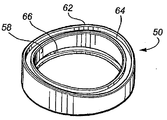
図面の図1に示すように、弁体10は、中心領域52を含み、その中心領域52は、下側のねじ切り部分54を有し、上側の平滑部分56を有する。カラー50の内面58は、その平滑な面56上で滑り嵌めであり、図面の図7および図8に示すユニオンナット60を使用して、取付けカラー50をタンク16の外面46に押し付ける。
As shown in FIG. 1 of the drawings, the
したがって、最初に弁体がタンクに差し込まれるときには、取付けカラー50は、後退した位置にあり、すなわち、ユニオンナット60が弁体の出口端部14に向かってねじ回しされている。一度フランジ40がタンクの内側に配置されると、ユニオンナット60は、反対方向にねじ回しされ、それにより、取付けカラー50をタンクの外面46に係合させる。
Thus, when the valve body is first inserted into the tank, the
出口42の周りに確実に封止を形成するために、取付けカラーは1対の封止材を有する。取付けカラー60の、タンクに接触する面、すなわち、図面の図6に示す封止面62は、タンクの円筒形の形状に沿うように鞍の形状をしている。封止面62に環状の溝64が形成され、その環状の溝64は、タンクの外面46と流体密封の封止材を形成するOリングなど(図示せず)を受ける。
To ensure a seal around the
同様に、取付けカラーの径方向内側の面58は、その中に環状の溝66を有し、その環状の溝66も、その内面58が弁体の平滑面56と共に封止することができるように、Oリングなどの封止材を受ける。取付けカラー50がタンクの外面46と堅固に係合するときに、これら2つの封止材が出口42を封止することが理解されよう。
Similarly, the radially
ユニオンナット60は、レンチなどの適切な工具を使用して、適位置に全体的にねじ止めされる。できるだけ滑らかに取付けカラー50の押付けを行うように、取付けカラー50とユニオンナット60の間に座金68が提供される。ユニオンナット60を確実に滑らかに締め付けるように、座金68を摩擦係数が比較的低い高分子材料から形成することができる。あるいは、座金68をエラストマー材料から形成することができる。
The
本明細書で説明したタイプの弁を圧力タンクに取り付けるために、必要とされるものは正確な直径だけであり、タンクの壁面に出口を開ける必要があり、その後、さらなる穴あけ、取付けねじ、固定クリップ、または他の取付け具を必要とせずに、弁体を適位置に嵌めることができることが理解されよう。一度フランジ40が出口を通して正確に差し込まれると、必要とされるものは、ユニオンナットが締め付けられ、それにより、取付けカラーを押し付けて、締め付けられ封止された構成にすることである。
In order to attach a valve of the type described here to a pressure tank, all that is required is an exact diameter and an outlet must be opened in the tank wall, after which further drilling, mounting screws, fixing It will be appreciated that the valve body can be fitted in place without the need for clips or other attachments. Once the
当然のことながら、本明細書で説明したユニオンナット60とは異なる押付け手段を使用することが可能である。例えば、複数の個々のねじ留め手段を採り入れることができる。しかし、圧力タンクに単一の出口を単に開けることによって、弁体を適位置に取り付けることができることが有利であると考えられる。
Of course, it is possible to use a pressing means different from the
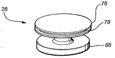
弁閉止部材38およびシリンダ26が、タンクの内部、すなわち、流路18の上流に配置されることが理解されよう。弁閉止機構は、比較的移動が短いピストンである。ピストン38は、2つのディスク、すなわち、ピストンディスク70および弁閉止ディスク72から形成される。それら2つのディスクは、本実施形態では直径の小さいスピンドルまたはネック74によって、同軸に整列して保持される。ピストンディスク70は、周囲縁部76を有し、その周囲縁部76は、Oリングの封止材などがそこに配置される溝78を含む。ピストンディスク70は、弁座24に向かって、また離れるようにシリンダ26内を摺動する。図8から明らかであるように、封止ディスク72が弁座24と係合するときに、流路18が閉じられ、弁の中を通る流れが不可能になる。
It will be appreciated that the valve closing member 38 and the
図8に示す実施形態では、弁閉止部材28は、端部キャップ29と弁閉止部材28との間で作用する圧縮ばね80によるばね補助式である。他のまたは代替の実施形態では、ばねによる補助を弁閉止部材28に提供する必要はない。さらに、端部キャップ29は、ブリード通路82を含み、そのブリード通路82は、圧力タンク内のそこからの圧縮空気が弁閉止部材28の下面に作用して、弁閉止部材28を弁座24に向けて、すなわち、閉位置に向けて押しやることを可能にする。弁を開くにためには、パイロット弁は空気に開放されており、シリンダ内の弁閉止部材28の背後の圧縮空気を、口34を通して排気することが可能になり、したがって、圧縮空気がピストンディスク70の下面84に作用し、それにより、弁閉止部材28を開位置に押しやる。下面84は比較的面積が大きいので、弁閉止部材の背後の圧縮空気が排出されるとすぐに、弁の速い開放が行われる。弁を閉じ
るためには、パイロット弁を使用して口34を閉じ、それにより圧縮空気がブリード通路82を通してシリンダ中に入ることが可能になり、それにより弁閉止部材28を弁座24に動かし、それにより弁を速く閉じる。
In the embodiment shown in FIG. 8, the
当然のことながら、パイロット通路36を通ってシリンダ26に入る高圧空気を使用して弁を作動させることが可能である。弁は、上述のものとは異なる構成のものであることが必要になるが、基本的に、弁は、逆に作動することになり、すなわち、高圧空気を使用することが、弁を閉じたままにするために使用され、その高圧空気を放散することにより、弁を開くように作動させる。
Of course, it is possible to operate the valve using high pressure air entering the
弁閉止ディスク72が、シリンダ支持アーム30の内部に形成された案内面88と摺動式に接触する外周部86を有することに留意されたい。これらの案内面88は、シリンダ26の内面と一緒に、弁閉止部材28を弁座24と位置合わせして保持するように働き、すなわち、弁閉止部材28が弁座24に向かって、またそこから離れるように動くときに、封止ディスク72の下面90は弁座24に平行である。
Note that the
弁閉止部材28を高品質のナイロン材料など、比較的計量のプラスチック材料から形成することができることが想定される。開閉運動の過酷さに耐え、しかも使用中に変形しない、適切なプラスチック材料を成形し、したがって比較的安価にすることができる。
It is envisioned that the
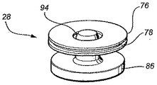
ピストンタイプの弁閉止部材の様々な異なる実施形態を、図面の図9から図11に示し、図9は、ブリード通路92を含む弁閉止部材を有する。図10は、圧縮ばねなしで使用される、ブリード通路のない弁閉止部材を示し、図11は、その上側表面に、図面の図8に示すタイプの圧縮ばねを配置する環状の溝94を有する弁閉止部材を示す。明らかに、図9から図11に示す弁閉止部材はそれぞれ、上記で説明したようにして適切なプラスチック材料から成形され、それぞれ溝78と、上記で参照される目的で案内面86を含む。
Various different embodiments of a piston-type valve closing member are shown in FIGS. 9-11 of the drawings, which has a valve closing member that includes a
本明細書で開示され定義された本発明は、文書または図面から言及されるかまたは明らかである2つ以上の個々の特徴を代替の組合せ全てに拡張することが理解されよう。これらの異なる組合せの全てが、本発明の様々な代替の態様を構成する。 It will be understood that the invention disclosed and defined herein extends two or more individual features mentioned or apparent from the document or drawing to all alternative combinations. All of these different combinations constitute various alternative aspects of the invention.
本明細書で使用される用語「comprises(備える、含む)」(またはその文法上の変形体)は、用語「includes(含む)」と等価であり、他の要素または特徴の存在を除外すると取るべきではないことも理解されよう。 As used herein, the term “comprises” (or grammatical variants thereof) is equivalent to the term “includes” and is taken to exclude the presence of other elements or features. It will be understood that it should not.
Claims (1)
Applications Claiming Priority (2)
| Application Number | Priority Date | Filing Date | Title |
|---|---|---|---|
| AU2005905498A AU2005905498A0 (en) | 2005-10-05 | Valve for control of high pressure air pulse | |
| AU2005905498 | 2005-10-05 |
Related Parent Applications (1)
| Application Number | Title | Priority Date | Filing Date |
|---|---|---|---|
| JP2008533818A Division JP5266052B2 (en) | 2005-10-05 | 2006-09-01 | Valve for controlling high-pressure air pulse |
Publications (1)
| Publication Number | Publication Date |
|---|---|
| JP2012087936A true JP2012087936A (en) | 2012-05-10 |
Family
ID=37905900
Family Applications (2)
| Application Number | Title | Priority Date | Filing Date |
|---|---|---|---|
| JP2008533818A Expired - Fee Related JP5266052B2 (en) | 2005-10-05 | 2006-09-01 | Valve for controlling high-pressure air pulse |
| JP2011258595A Pending JP2012087936A (en) | 2005-10-05 | 2011-11-28 | Valve for controlling high pressure air pulse |
Family Applications Before (1)
| Application Number | Title | Priority Date | Filing Date |
|---|---|---|---|
| JP2008533818A Expired - Fee Related JP5266052B2 (en) | 2005-10-05 | 2006-09-01 | Valve for controlling high-pressure air pulse |
Country Status (13)
| Country | Link |
|---|---|
| US (2) | US7984727B2 (en) |
| EP (1) | EP1931912B1 (en) |
| JP (2) | JP5266052B2 (en) |
| KR (1) | KR101424114B1 (en) |
| CN (2) | CN101979909B (en) |
| AU (1) | AU2006206062B2 (en) |
| BR (1) | BRPI0616919A2 (en) |
| CA (1) | CA2624118C (en) |
| DK (1) | DK1931912T3 (en) |
| ES (1) | ES2398368T3 (en) |
| MX (1) | MX2008004568A (en) |
| NZ (2) | NZ567003A (en) |
| WO (1) | WO2007038826A1 (en) |
Families Citing this family (8)
| Publication number | Priority date | Publication date | Assignee | Title |
|---|---|---|---|---|
| US8875725B2 (en) | 2012-10-09 | 2014-11-04 | Brasscraft Manufacturing Company | Fluid connector with integrated excess flow valve |
| US8640733B1 (en) | 2012-10-09 | 2014-02-04 | Brasscraft Manufacturing Company | Excess flow cartridge |
| US9383025B2 (en) | 2013-12-16 | 2016-07-05 | Brasscraft Manufacturing Company | Excess flow valve with cage |
| EP3070219B1 (en) * | 2015-03-20 | 2020-12-16 | ABB Schweiz AG | Explosion vent |
| US10792408B2 (en) * | 2016-10-27 | 2020-10-06 | Baxter International Inc. | Medical fluid therapy machine including readily accessible pneumatic manifold and valves therefore |
| IT201900009477A1 (en) * | 2019-06-19 | 2020-12-19 | Trimec S R L | VALVE DEVICE FOR CLEANING INDUSTRIAL FILTERS |
| WO2021032618A1 (en) * | 2019-08-20 | 2021-02-25 | Luxembourg Patent Company S.A. | Gas cylinder valve with radially extending operating handle |
| CN112128513B (en) * | 2020-09-09 | 2022-05-10 | 湖南衡兴环保科技开发有限公司 | A bag filter pulse tube with long service life |
Citations (6)
| Publication number | Priority date | Publication date | Assignee | Title |
|---|---|---|---|---|
| JPS58187260U (en) * | 1982-06-07 | 1983-12-13 | 旭有機材工業株式会社 | water hydrant |
| JPS62118712U (en) * | 1986-01-21 | 1987-07-28 | ||
| JPH07217767A (en) * | 1994-01-28 | 1995-08-15 | Ckd Corp | 3-position open / close valve |
| JP2000170927A (en) * | 1996-11-25 | 2000-06-23 | Ckd Corp | Valve unit |
| JP2001271959A (en) * | 2000-03-27 | 2001-10-05 | Smc Corp | 2-port valve |
| JP2003014155A (en) * | 2001-06-27 | 2003-01-15 | Kitz Sct:Kk | Variable flow valve |
Family Cites Families (39)
| Publication number | Priority date | Publication date | Assignee | Title |
|---|---|---|---|---|
| US2778598A (en) * | 1953-07-20 | 1957-01-22 | Exxon Research Engineering Co | Valve with pressure sealing device |
| DE1254416B (en) * | 1959-10-06 | 1967-11-16 | Continental Gummi Werke Ag | Outlet valve for transport container |
| US3451423A (en) * | 1967-12-15 | 1969-06-24 | Hills Mccanna Co | Fluid actuated diaphragm valve |
| US3729168A (en) * | 1971-08-13 | 1973-04-24 | Acf Ind Inc | Piston stop for piston operated valve |
| CS167725B1 (en) * | 1974-02-14 | 1976-05-28 | ||
| US3910550A (en) * | 1974-05-13 | 1975-10-07 | Illinois Tool Works | Drain plug assembly |
| US4003399A (en) * | 1975-02-25 | 1977-01-18 | Fischer Edward J | Anti-syphon device for a water supply line |
| JPS521627A (en) * | 1975-06-24 | 1977-01-07 | Hitachi Ltd | Air operable valve devices |
| US4128110A (en) * | 1976-12-27 | 1978-12-05 | Pneutek, Inc. | Control valves |
| US4194770A (en) * | 1978-03-01 | 1980-03-25 | Eaton Corporation | Compression fitting |
| BE868125A (en) * | 1978-06-15 | 1978-10-02 | Race Maurice | PROCESS FOR WITHDRAWING FLAMMABLE OR DANGEROUS LIQUIDS USING A SAFETY VALVE |
| FR2444834A1 (en) * | 1978-12-18 | 1980-07-18 | Procal | Second fitting for water tank corrosion protection electrode - comprises threaded cylinder secured to tank wall by nut and shoulder bearing against tank inside wall |
| GB2050571B (en) * | 1979-05-31 | 1983-03-09 | Freezinhot Bottle Co Ltd | Lever tap unit |
| US4239058A (en) * | 1979-07-16 | 1980-12-16 | Acf Industries, Incorporated | Pull type relay valve with automatic lockout |
| US4267861A (en) * | 1979-11-05 | 1981-05-19 | Rk Industries | Plural modular fluid transfer valves |
| GB2123929B (en) * | 1982-06-15 | 1986-01-08 | Rodney Gomersall | Valves for pressure vessels |
| US4522230A (en) * | 1983-02-23 | 1985-06-11 | Rockwell International Corporation | Orifice plate seal ring for controlled closure check valve |
| DK80185A (en) * | 1985-02-21 | 1986-08-22 | Joergen Hansen | ADJUSTABLE AIR VALVE FOR AN INFLATIBLE BODY |
| ZA875979B (en) * | 1986-09-03 | 1988-04-27 | Cornelius Gideon Kotze Jacobus | Device for forming a flow connection to the interior of a container |
| DE3917989A1 (en) * | 1989-06-02 | 1990-12-06 | Bayer Ag | DEVICE FOR REPAIRING OR REPLACING CONTAINER CONNECTORS OF ENAMELED APPARATUS |
| US5027852A (en) * | 1990-06-04 | 1991-07-02 | Keystone International Holdings Corp. | Pilot valve for control valves and method of operation |
| JPH0653B2 (en) * | 1990-07-19 | 1994-01-05 | 幸太郎 土本 | Powdered food sterilizer |
| SE468721B (en) * | 1991-07-04 | 1993-03-08 | Flaekt Ab | VALVE DEVICE FOR GENERATING SHORT-TERM PRESSURE PULSES EXAMPLE FOR BLEASING BASIC FILTER ELEMENTS |
| JPH0630599U (en) * | 1992-09-22 | 1994-04-22 | 日本鋼管継手株式会社 | Pipe fitting |
| FR2712062B1 (en) * | 1993-11-03 | 1995-12-15 | Legris Sa | Device intended for the passage of a pipeline through a wall. |
| DE19523219A1 (en) * | 1995-06-27 | 1997-01-02 | Bosch Gmbh Robert | Device for time-dependent control of the regeneration period of an air dryer |
| US5662140A (en) * | 1995-10-16 | 1997-09-02 | Fireman's Friend Engineering, Inc. | Internally mounted high pressure hydraulic valve for vehicularly mounted water receiving tanks |
| JPH1073171A (en) * | 1996-07-03 | 1998-03-17 | Kubota Corp | Emergency valve for water tank |
| AUPO160596A0 (en) * | 1996-08-13 | 1996-09-05 | Hill, Dianna Adele | Improved mains pressure flusher valve |
| IT1289460B1 (en) * | 1996-12-18 | 1998-10-15 | Scoprega S P A | VALVE STRUCTURE PARTICULARLY FOR PNEUMATIC TANK |
| US6035883A (en) * | 1998-03-13 | 2000-03-14 | Eaton Corporation | Weldable vapor vent valve for fuel tanks |
| JP3631053B2 (en) * | 1999-08-17 | 2005-03-23 | アロン化成株式会社 | Synthetic resin nut tightening branch |
| KR200207899Y1 (en) * | 2000-07-25 | 2000-12-15 | 정인선 | Clamp for divergence of flexible hose |
| US6557736B1 (en) * | 2002-01-18 | 2003-05-06 | Heiner Ophardt | Pivoting piston head for pump |
| JP2004092824A (en) * | 2002-09-02 | 2004-03-25 | Fujikin Inc | Fluid controller |
| DE20217821U1 (en) * | 2002-11-18 | 2003-03-20 | Schwan-Stabilo Cosmetics GmbH & Co., 90562 Heroldsberg | make-up device |
| ATE331912T1 (en) * | 2003-02-27 | 2006-07-15 | Delphi Tech Inc | REVERSIBLE SLIDE |
| CN2685664Y (en) * | 2004-03-05 | 2005-03-16 | 罗荣森 | Plastic stop valve |
| JP2007016977A (en) * | 2005-07-11 | 2007-01-25 | Smc Corp | Pilot operated 2-port valve |
-
2006
- 2006-09-01 KR KR1020087010895A patent/KR101424114B1/en not_active Expired - Fee Related
- 2006-09-01 DK DK06774915T patent/DK1931912T3/en active
- 2006-09-01 EP EP20060774915 patent/EP1931912B1/en not_active Not-in-force
- 2006-09-01 US US12/088,914 patent/US7984727B2/en not_active Expired - Fee Related
- 2006-09-01 CA CA 2624118 patent/CA2624118C/en not_active Expired - Fee Related
- 2006-09-01 AU AU2006206062A patent/AU2006206062B2/en not_active Ceased
- 2006-09-01 BR BRPI0616919-8A patent/BRPI0616919A2/en not_active IP Right Cessation
- 2006-09-01 CN CN201010119787.5A patent/CN101979909B/en not_active Expired - Fee Related
- 2006-09-01 CN CN2006800367974A patent/CN101300448B/en not_active Expired - Fee Related
- 2006-09-01 JP JP2008533818A patent/JP5266052B2/en not_active Expired - Fee Related
- 2006-09-01 NZ NZ567003A patent/NZ567003A/en not_active IP Right Cessation
- 2006-09-01 NZ NZ583575A patent/NZ583575A/en not_active IP Right Cessation
- 2006-09-01 MX MX2008004568A patent/MX2008004568A/en active IP Right Grant
- 2006-09-01 ES ES06774915T patent/ES2398368T3/en active Active
- 2006-09-01 WO PCT/AU2006/001286 patent/WO2007038826A1/en not_active Ceased
-
2011
- 2011-05-26 US US13/116,708 patent/US8434733B2/en not_active Expired - Fee Related
- 2011-11-28 JP JP2011258595A patent/JP2012087936A/en active Pending
Patent Citations (6)
| Publication number | Priority date | Publication date | Assignee | Title |
|---|---|---|---|---|
| JPS58187260U (en) * | 1982-06-07 | 1983-12-13 | 旭有機材工業株式会社 | water hydrant |
| JPS62118712U (en) * | 1986-01-21 | 1987-07-28 | ||
| JPH07217767A (en) * | 1994-01-28 | 1995-08-15 | Ckd Corp | 3-position open / close valve |
| JP2000170927A (en) * | 1996-11-25 | 2000-06-23 | Ckd Corp | Valve unit |
| JP2001271959A (en) * | 2000-03-27 | 2001-10-05 | Smc Corp | 2-port valve |
| JP2003014155A (en) * | 2001-06-27 | 2003-01-15 | Kitz Sct:Kk | Variable flow valve |
Also Published As
| Publication number | Publication date |
|---|---|
| CN101979909B (en) | 2014-04-09 |
| KR20080068047A (en) | 2008-07-22 |
| EP1931912A1 (en) | 2008-06-18 |
| CN101300448A (en) | 2008-11-05 |
| BRPI0616919A2 (en) | 2011-07-05 |
| KR101424114B1 (en) | 2014-08-01 |
| DK1931912T3 (en) | 2013-02-11 |
| EP1931912A4 (en) | 2010-07-14 |
| CA2624118A1 (en) | 2007-04-12 |
| HK1125992A1 (en) | 2009-08-21 |
| NZ567003A (en) | 2010-07-30 |
| EP1931912B1 (en) | 2012-11-07 |
| CN101300448B (en) | 2013-05-29 |
| AU2006206062B2 (en) | 2013-03-07 |
| JP2009510364A (en) | 2009-03-12 |
| US8434733B2 (en) | 2013-05-07 |
| AU2006206062A1 (en) | 2007-04-19 |
| CN101979909A (en) | 2011-02-23 |
| WO2007038826A1 (en) | 2007-04-12 |
| CA2624118C (en) | 2014-04-01 |
| MX2008004568A (en) | 2008-09-04 |
| JP5266052B2 (en) | 2013-08-21 |
| US7984727B2 (en) | 2011-07-26 |
| US20110226976A1 (en) | 2011-09-22 |
| US20080251135A1 (en) | 2008-10-16 |
| NZ583575A (en) | 2011-09-30 |
| ES2398368T3 (en) | 2013-03-15 |
Similar Documents
| Publication | Publication Date | Title |
|---|---|---|
| US8434733B2 (en) | Valve for control of high pressure air pressure air pulse | |
| US10060553B2 (en) | Valve | |
| AU2004208759B2 (en) | Valve and method for providing a fluid pulse | |
| JPS623344B2 (en) | ||
| CA2696033A1 (en) | Filter housing assembly | |
| JP2013521454A (en) | Diaphragm valve | |
| US7517376B2 (en) | Reverse pulse cleaning of filter elements | |
| US20160230902A1 (en) | Valve | |
| US20150060708A1 (en) | Bellows valve with valve body cylinder adapter | |
| JP2001108131A (en) | Piston valve | |
| HK1125992B (en) | Valve for use in the control of pressurised air from a pressure tank | |
| CN109237093B (en) | Water pipe valve | |
| AU2009201139A1 (en) | Reverse pulse cleaning of filter elements | |
| RU53397U1 (en) | VALVE | |
| CN214466397U (en) | Automatic air-filling valve | |
| CN209385714U (en) | It is a kind of can rate controlling switch pneumatic valve system | |
| ITPR970013A1 (en) | AUTOMATIC CONTROL VALVE FOR FLUIDS. |
Legal Events
| Date | Code | Title | Description |
|---|---|---|---|
| A131 | Notification of reasons for refusal |
Free format text: JAPANESE INTERMEDIATE CODE: A131 Effective date: 20130815 |
|
| A977 | Report on retrieval |
Free format text: JAPANESE INTERMEDIATE CODE: A971007 Effective date: 20130815 |
|
| A02 | Decision of refusal |
Free format text: JAPANESE INTERMEDIATE CODE: A02 Effective date: 20140512 |