JP2012056591A - Liquid dispensing container - Google Patents
Liquid dispensing container Download PDFInfo
- Publication number
- JP2012056591A JP2012056591A JP2010200185A JP2010200185A JP2012056591A JP 2012056591 A JP2012056591 A JP 2012056591A JP 2010200185 A JP2010200185 A JP 2010200185A JP 2010200185 A JP2010200185 A JP 2010200185A JP 2012056591 A JP2012056591 A JP 2012056591A
- Authority
- JP
- Japan
- Prior art keywords
- nozzle
- liquid
- container
- nozzle member
- inclined bottom
- Prior art date
- Legal status (The legal status is an assumption and is not a legal conclusion. Google has not performed a legal analysis and makes no representation as to the accuracy of the status listed.)
- Granted
Links
Images


Abstract
Description
本発明は、液体洗剤、柔軟剤、液体漂白剤等の水性液剤や油性液剤等の液体製品を詰め替えて使用可能な液体注出容器に関する。 The present invention relates to a liquid dispensing container that can be used by refilling a liquid product such as an aqueous liquid agent such as a liquid detergent, a softening agent, and a liquid bleaching agent or an oily liquid agent.
従来、液体洗剤等の液体製品を収容するボトル(容器本体)と、内容液を注出するノズルを有して前記ボトルに装着されるノズルキャップ(ノズル部材)と、前記ノズルから注出される内容液を計量する計量筒部が設けられて、前記ノズルキャップに着脱自在に装着される計量キャップとを備えた液体注出容器が、一般に使用されている。 Conventionally, a bottle (container body) that contains a liquid product such as a liquid detergent, a nozzle cap (nozzle member) that has a nozzle that pours the content liquid and is attached to the bottle, and a content that is poured out from the nozzle In general, a liquid dispensing container is used that includes a measuring cylinder portion that measures a liquid and includes a measuring cap that is detachably attached to the nozzle cap.
この種の液体注出容器において、液を計量する通常使用時には、まず計量キャップをノズルキャップから外して、ノズルキャップから計量キャップに液を注ぎ出して計量する。 In this type of liquid dispensing container, during normal use in which the liquid is measured, the measuring cap is first removed from the nozzle cap, and the liquid is poured from the nozzle cap into the measuring cap and weighed.
このとき、計量キャップを回転させて外す際に、ノズルキャップが計量キャップと共回りして、計量キャップと一緒にボトルから外れてしまうことを防止するために、一般にノズルキャップはボトルに対して、打ち込み嵌合やラチェット嵌合などの方法によって、開閉不可能に嵌合されている。 At this time, in order to prevent the nozzle cap from rotating together with the measuring cap when the measuring cap is rotated and removed from the bottle together with the measuring cap, the nozzle cap is generally attached to the bottle. It is fitted so that it cannot be opened and closed by methods such as driving fitting and ratchet fitting.
このような構造から、上記液体注出容器においては、パウチ等の詰め替え容器からボトル内に液を注ぎ込む詰め替え作業時に、ノズルキャップのノズルを狙って液を注ぎ込まなければならず、作業に神経を使う。 With such a structure, in the liquid dispensing container, when refilling the liquid into the bottle from a refilling container such as a pouch, the liquid must be poured aiming at the nozzle of the nozzle cap. .
また、ノズルの径が細く、開口断面積が小さなノズルキャップの場合には、詰め替え作業時に液がボトル内に流下する速度が遅くなり、パウチから液を注ぎ込む勢いを強くすると、ボトル内からの空気置換が間に合わなくなり、ノズルキャップ内に液が滞留してしまう。このように、空気置換が間に合わないとボトル内から空気の流出により激しく泡立ち、ノズルキャップの内の液面が上昇し、溢れてしまうという不具合に繋がる虞がある。 Also, in the case of a nozzle cap with a small nozzle diameter and a small opening cross-sectional area, the speed at which the liquid flows down into the bottle during refilling work is slow, and if the liquid is poured from the pouch, The replacement cannot be made in time, and the liquid stays in the nozzle cap. In this way, if the air replacement is not in time, there is a risk that bubbles will be generated violently by the outflow of air from the inside of the bottle and the liquid level in the nozzle cap will rise and overflow.
液体の注ぎ口に関して、実公平01−20289号公報(:特許文献1)では、注ぎ口、副注ぎ口、空気吸い込み口(発音部)から構成されている注出具が開示されている。また、実公平01−23965号公報(:特許文献2)では、主流管、分流管、吸気管から構成された注出用ノズルがある。また、実公昭62−44923号公報(:特許文献3)では、主開口、副開口、空気吸入管から構成された注出具が開示されている。また、特開平01−294451号公報(:特許文献4)、注入口と空気導入パイプから構成される注出具が開示される。しかしながら、これら特許文献1〜4記載の注出具は、いずれも注ぎ口が二つに分かれ注ぎ出しのみ考慮し、詰め替えを全く想定していないものであるので詰め替えが困難で現実的でないものである。 Regarding a liquid spout, Japanese Utility Model Publication No. 01-20289 (Patent Document 1) discloses a pouring tool composed of a spout, a sub-pour, and an air inlet (sound generator). Moreover, in Japanese Utility Model Publication No. 01-23965 (Patent Document 2), there is a nozzle for pouring composed of a main flow pipe, a diversion pipe, and an intake pipe. Japanese Utility Model Publication No. 62-44923 (Patent Document 3) discloses a pouring tool composed of a main opening, a sub-opening, and an air suction pipe. Japanese Patent Laid-Open No. 01-294451 (Patent Document 4) discloses a pouring tool composed of an inlet and an air introduction pipe. However, the pouring tools described in these Patent Documents 1 to 4 are not practical because refilling is difficult because the spout is divided into two parts and only pouring is considered and no refilling is assumed. .
なお、特開平09−193954号公報(:特許文献5)では、本体キャップに突き刺し部材を有する容器連結具が開示されている。しかしながら、この容器連結具では、スパイク針が突き刺ささるスパウト部材をパウチ容器に設ける必要があり、そのようなスパウト部材をパウチ容器に設けるという特別な構成が必要なため、一般的なパウチ容器では、使用できない汎用性のないものである。 Note that Japanese Patent Application Laid-Open No. 09-193904 (Patent Document 5) discloses a container connector having a piercing member in a main body cap. However, in this container coupling tool, it is necessary to provide a spout member into which the spike needle is inserted in the pouch container, and since a special configuration of providing such a spout member in the pouch container is necessary, in a general pouch container, It cannot be used and is not versatile.
一方、特開2008−155953号公報(:特許文献6)では、傾斜底壁を有して容器本体を開閉する計量キャップが開示されており、この場合、傾斜底壁の最下部側に、注ぎ口のほぼ中央まで下方に傾斜する傾斜壁が設けられているが、液の詰め替えの際に空気置換がしにくいので、上記のボトル内からの空気置換が間に合わなくなり、ノズルキャップ内に液が滞留して、ノズルキャップの内の液面が上昇し、溢れてしまうという不具合に繋がる等の問題が残るものである。 On the other hand, Japanese Patent Application Laid-Open No. 2008-155953 (Patent Document 6) discloses a measuring cap that has an inclined bottom wall and opens and closes the container body. In this case, the measuring cap is poured on the lowermost side of the inclined bottom wall. There is an inclined wall that slopes down to almost the center of the mouth, but it is difficult to replace air when refilling the liquid, so air replacement from the inside of the bottle is not in time, and liquid stays in the nozzle cap. As a result, there remains a problem that the liquid level in the nozzle cap rises and overflows.
本発明は、斯かる実情に鑑み、ノズルキャップの詰め替え性に関する不具合を改善することを目的としたものであり、計量作業を行う通常使用時には、従来のノズルキャップと同等の使用性を有し、かつ、詰め替え作業時には、ボトル内に液が速やかに流下し、ノズル内に液が滞留して液面が上昇し溢れるといった不具合が生じることのない詰め替え作業性に優れる液体注出容器を提供しようとするものである。 In view of such circumstances, the present invention aims to improve the problems related to the refillability of the nozzle cap, and has a usability equivalent to that of a conventional nozzle cap during normal use for measuring work. In addition, at the time of refilling work, an attempt is made to provide a liquid dispensing container that is excellent in refilling workability, in which the liquid quickly flows down in the bottle, the liquid stays in the nozzle, and the liquid level rises and overflows. To do.
本発明は液体注出容器にかかるものであり、内容液を収納する容器本体と、内容液を注出するノズルを有し前記容器本体の口首部に装着されるノズル部材と、前記ノズルから注出される内容液を量り取る計量筒部を有して前記ノズル部材に着脱自在に装着されるキャップとを備えた液体注出容器であって、
前記ノズル部材が、ノズルの基部から垂直方向に立ち上がってその側面に開放部を有する樋状のノズルと、ノズル基部からノズル外方向に向かって結合される環状傾斜底部と、前記環状傾斜底部を経て上方に前記ノズルとの間に空間を隔てて垂直方向に立ち上がる筒状壁部とを有し、
前記樋状のノズルの内側には、容器本体内の内容液を容器外に注出するための開口部が設けられ、
前記キャップを前記ノズル部材に装着する際には、前記空間に前記キャップの計量筒部が挿入されるようにし、
前記ノズルの先端に液剤の注ぎ口が形成され、前記環状傾斜底部はノズル軸心を挟んで前記の注ぎ口と反対の方向に下降するように形成され、
前記キャップの外壁面にフランジ部が形成され、このフランジの先端部に前記ノズル部材の筒状壁部の上端に形成されたネジ部に螺合するネジ部が形成され、前記キャップのネジ部による前記筒状壁部上端部への螺合により前記キャップが前記筒状壁部への上端部に装着され、
前記ノズル部材の筒状壁部の外壁面にフランジ部を介して垂下した第二周壁が形成され、この第二周壁の先端部に前記容器本体の口首部に形成されたネジ部に螺合するネジ部が形成され、前記第二周壁のネジ部による前記容器本体口首部への螺合により前記ノズル部材が前記容器本体の口首部に装着される液体注出容器において、
前記ノズル部材の前記筒状壁部の内側に、詰め替え時にノズル部材を介して容器本体内に液を注ぎ込む際に、容器本体内の空気を容器外に排出するための空気置換流路を有することを特徴とする液体注出容器である。
The present invention relates to a liquid dispensing container, a container main body that contains the content liquid, a nozzle member that has a nozzle for pouring the content liquid and is attached to the mouth portion of the container main body, and a liquid that is poured from the nozzle. A liquid dispensing container having a measuring cylinder portion for weighing out the content liquid to be dispensed and having a cap detachably attached to the nozzle member;
The nozzle member rises in the vertical direction from the base of the nozzle and has a bowl-shaped nozzle having an open portion on its side surface, an annular inclined bottom coupled from the nozzle base toward the nozzle outward direction, and the annular inclined bottom. A cylindrical wall portion that rises in the vertical direction with a space between the nozzle and the upper portion;
Inside the bowl-shaped nozzle, there is provided an opening for pouring the content liquid in the container body out of the container,
When mounting the cap on the nozzle member, the measuring tube portion of the cap is inserted into the space,
A liquid spout is formed at the tip of the nozzle, and the annular inclined bottom is formed to descend in a direction opposite to the spout across the nozzle axis,
A flange portion is formed on the outer wall surface of the cap, and a screw portion that is screwed to a screw portion formed on the upper end of the cylindrical wall portion of the nozzle member is formed at the front end portion of the flange. The cap is attached to the upper end to the cylindrical wall by screwing to the upper end of the cylindrical wall,
A second peripheral wall is formed on the outer wall surface of the cylindrical wall portion of the nozzle member via a flange portion, and is screwed to a screw portion formed on the mouth portion of the container main body at the distal end portion of the second peripheral wall. In the liquid dispensing container in which a screw part is formed, and the nozzle member is attached to the mouth part of the container body by screwing to the container body mouth part by the thread part of the second peripheral wall,
An air replacement flow path for discharging the air in the container body to the outside of the container body when the liquid is poured into the container body through the nozzle member at the time of refilling inside the cylindrical wall portion of the nozzle member. A liquid dispensing container characterized by
本発明においては、前記空気置換流路が、前記樋状のノズル内側に、対向するノズル内壁面を繋ぐようにして垂直方向に延設された分離壁により構成される筒状の空間であることが好適である。 In the present invention, the air replacement flow path is a cylindrical space constituted by a separation wall extending in the vertical direction so as to connect the inner wall surfaces of the opposed nozzles inside the bowl-shaped nozzle. Is preferred.
本発明においては、環状傾斜底部が、前記ノズル部材の注ぎ口側から前記ノズル部材の開放部側に向かって垂直方向下向きに傾斜する第一の傾斜底部と、前記ノズルの開放部側から前記ノズルの中央に向かって垂直方向下向きに傾斜する第二の傾斜底部とから構成され、
前記第一の傾斜底部と、前記第二の傾斜底部とは、段差によって連結されており、
前記第二の傾斜底部の下端縁には、液注出時の空気置換用の切欠き部が設けられていることが好適である。
In the present invention, the annular inclined bottom portion is inclined in the vertical downward direction from the spout side of the nozzle member toward the open portion side of the nozzle member, and the nozzle from the open portion side of the nozzle And a second inclined bottom portion inclined downward in the vertical direction toward the center of the
The first inclined bottom portion and the second inclined bottom portion are connected by a step,
It is preferable that the lower end edge of the second inclined bottom portion is provided with a notch portion for air replacement during liquid dispensing.
本発明においては、前記ノズル部材の前記ノズルの内側に、突き刺し部材を有することが好適である。 In this invention, it is suitable to have a piercing member inside the nozzle of the nozzle member.
本発明の液体注出容器によれば、ノズル部材の前記筒状壁部の内側に、詰め替え時にノズル部材を介して容器本体内に液を注ぎ込む際に、容器本体内の空気を容器外に排出するための空気置換流路を有するので、ノズル部材内に勢いよく液を注ぎ込んでも容器本体内からの空気置換がスムーズに行うことができ、ボトル内に液が速やかに流下し、ノズル内に液が滞留して液面が上昇したり、液が溢れたりするといった不具合の確実な防止という効果を奏する。 According to the liquid dispensing container of the present invention, when the liquid is poured into the container body through the nozzle member when refilling the inside of the cylindrical wall portion of the nozzle member, the air in the container body is discharged out of the container. Since the air replacement flow path is used, the liquid can be smoothly replaced from the inside of the container body even if the liquid is poured into the nozzle member vigorously, and the liquid quickly flows down into the bottle, and the liquid into the nozzle. Stays and the liquid level rises or the liquid overflows.
なお、前記空気置換流路を、前記樋状のノズル内側に、対向するノズル内壁面を繋ぐようにして垂直方向に延設された分離壁により構成される筒状の空間とすることによって、詰め替えの際にノズル部材に液を注ぎ込むときに液が分離壁を乗り越えることがなく空気置換流路に液が流れ込み難く、上記本発明の効果がより確実に発揮される。また、通常の使用の際に、ノズルから液を注ぎだす時には、上記の空気置換流路が液注出流路として作用するので、不必要な空気置換が生じて液が流れ出しすぎノズルの脇まで液が周り込んでしまい液垂れの問題が生じるということが無い。 The air replacement flow path is refilled by forming a cylindrical space constituted by a separating wall extending in the vertical direction so as to connect the inner wall surface of the nozzle facing the inner side of the bowl-shaped nozzle. In this case, when the liquid is poured into the nozzle member, the liquid does not pass over the separation wall, and the liquid does not easily flow into the air replacement flow path, so that the effect of the present invention is more reliably exhibited. In addition, when the liquid is poured out from the nozzle during normal use, the air replacement flow path acts as a liquid discharge flow path, so that unnecessary air replacement occurs and the liquid flows out too much to the side of the nozzle. There is no problem of liquid dripping around and causing dripping.
また、環状傾斜底部が、前記ノズル部材の注ぎ口側から前記ノズル部材の開放部側に向かって垂直方向下向きに傾斜する第一の傾斜底部と、前記ノズルの開放部側から前記ノズルの中央に向かって垂直方向下向きに傾斜する第二の傾斜底部とから構成され、前記第一の傾斜底部と、前記第二の傾斜底部とは、段差によって連結されており、前記第二の傾斜底部の下端縁には、液注出時の空気置換用の切欠き部を設けることによって、ノズル開放部の傾斜底部の傾斜をより急傾斜にすることできるので、液をより速やかにボトル内に流下させることができる。 Also, an annular inclined bottom portion is formed in a first inclined bottom portion that is inclined downward in the vertical direction from the spout side of the nozzle member toward the open portion side of the nozzle member, and from the open portion side of the nozzle to the center of the nozzle. A second inclined bottom portion that is inclined downward vertically, and the first inclined bottom portion and the second inclined bottom portion are connected by a step, and a lower end of the second inclined bottom portion By providing a notch part for air replacement at the time of liquid pouring on the edge, the inclination of the inclined bottom part of the nozzle opening part can be made steeper, so that the liquid can flow down into the bottle more quickly. Can do.
また、前記ノズル部材の前記ノズルの内側に、突き刺し部材を有するものにすれば、口元に薄膜を有するのにパウチの薄膜をこの突き刺し部材で突き刺すことにより、パウチが開口し、速やかに液を流下させ詰め替えることができる。この際、空気置換流路が確実に確保されるので、流下する液がノズル部材内に滞留し、溢れたりするということがない。 In addition, if the nozzle member has a piercing member inside the nozzle, the pouch is opened by the piercing member even though it has a thin film at the mouth, and the liquid quickly flows down. Can be refilled. At this time, since the air replacement flow path is ensured, the flowing liquid does not stay in the nozzle member and does not overflow.
以下、本発明の実施形態について、添付図面を参照して説明する。 Embodiments of the present invention will be described below with reference to the accompanying drawings.
以下の説明において上下と言う場合には、容器を使用しない静置状態においての上、下(鉛直上方、下方:図1において符号U、Dで示す)をいう。もちろん、使用時に注ぎ出すときにはノズル部材14が下向きに傾けるが、説明上、注出容器の上部にノズル部材14が設けられる。
In the following description, the terms “upper and lower” refer to upper and lower (vertically upward and downward: indicated by reference symbols U and D in FIG. 1) in a stationary state where no container is used. Of course, the
図1〜図2は第1の実施形態に係る液体注出容器の説明図である。 1-2 is explanatory drawing of the liquid extraction container which concerns on 1st Embodiment.
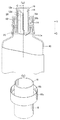
第1の実施形態に係る液体注出容器は、図1に示すように、内容液を収納する容器本体10と、内容液を注出するノズル12を有し前記容器本体10の口首部10aに装着されるノズル部材14と、前記ノズル12から注出される内容液を量り取る計量筒部16を有し、前記ノズル部材14に着脱自在に装着されるキャップ18を備えた液体注出容器に関するものである。
As shown in FIG. 1, the liquid dispensing container according to the first embodiment includes a container
図2に示すように、前記液注出容器では、前記ノズル部材14が、ノズル12の基部12aから垂直方向に立ち上がってそのノズル12側面に開放部12bを有し、開放部12bがノズル12の先端に開口した注ぎ口12eに連続する樋状のノズル12と、ノズル基部12aからノズル12外径方向に向かって概略板状に展開形成されて結合される環状傾斜底部20と、前記環状傾斜底部20を経てその環状傾斜底部20の周囲に、前記ノズル12との間に空間22を隔てて垂直方向に上方向きに立ち上がる筒状壁部24とを有している。
As shown in FIG. 2, in the liquid dispensing container, the
実施形態では、図2に示すように、ノズル12は、略筒体形状であって、その側面部に上下に渡って切り欠いた開放部12bを有しており、ノズル12先端の注ぎ口12eが開放部12bに向かって下がるように斜めに形成されている。
In the embodiment, as shown in FIG. 2, the
前記樋状のノズル12の内側には、容器本体10内の内容液をノズル12を介して容器外に注出するための貫通孔の開口部12cがノズル基部12a内側に位置して形成される。また、前記開口部12cの前記樋状のノズル12の開放部12b側端縁には、開口部12cに連続して液注出時の空気置換用の切欠き部12dが半円形状に切り欠いて形成されている。前記キャップ18を前記ノズル部材14に装着する際には、前記空間22に前記キャップ18の計量筒部16が挿入されるようにし計量筒部16の壁が当該空間22に入り込むようになっている。
Inside the bowl-shaped
また、前記ノズル12はその先端(ノズル基部12aが下方側とすればその反対の上方側)に注ぎ口12eが開口して形成され、注ぎ口12eが開放部12bに連続するので、注ぎ口12eの周囲縁は前記開放部12bの周囲縁に向かって下がるように斜めに形成されている。ノズル12の立設位置は、ノズル部材14の軸心(符号Oで示す)から径方向一方側に偏って形成され、前記環状傾斜底部20は前記ノズル軸心Oを挟んで前記の注ぎ口12eと反対の方向に下降する斜面が周囲に形成されている。
Further, the
ここで、図1に示すように、前記キャップ18の外壁面に略袴状にフランジ部18aが形成され、このフランジ部18aの内側面に前記ノズル部材14における筒状壁部24の上端の外面に形成されたネジ部24a(雄ネジ)に螺合するネジ部18b(雌ネジ)が形成される。この場合、キャップ18の計量筒部16をノズル部材14の空間22内に差込んで、フランジ部18aによって筒状壁部24を覆うように装着されて、前記キャップ18のネジ部18bによる前記筒状壁部24上端部への螺合により、前記キャップ18が前記筒状壁部24への上端部に装着される。
Here, as shown in FIG. 1, a
また、図1、図2に示すように、前記ノズル部材14においては、その筒状壁部24の外壁面にやや水平方向に展開するフランジ部26を介して垂下した第二周壁24bが袴状に形成され、この第二周壁24bの先端部内周面に、前記容器本体10の口首部10a外面に形成されたネジ部に螺合するネジ部24cが形成される。前記第二周壁24bのネジ部24cによる前記容器本体10の口首部10aへの螺合により、前記ノズル部材14が前記容器本体10の口首部10aに装着される液体注出容器の構成を有している。
As shown in FIGS. 1 and 2, in the
前記ノズル部材14の前記筒状壁部24の内側に、詰め替え時にノズル部材14を介して容器本体10内にパウチ等の詰め替え容器から液を注ぎ込む際に、容器本体10内の空気を容器外に排出するための空気置換流路28を略筒状に形成している。
When the liquid is poured from the refilling container such as a pouch into the container
具体的には、前記空気置換流路28は、前記樋状のノズル12内側に、対向するノズル12の内壁面を繋ぐようにして垂直方向に延設された分離壁28a内部の空間を流路とするものである。図2に示す第1の実施形態では、空気置換流路28の分離壁28aはノズル壁面から離れる方向に膨出する弧形状の横断面の曲面板構造を呈し、分離壁28aとノズル12内壁面とによって、管状構造を呈した空気置換流路28を形成する。
Specifically, the air
また、環状傾斜底部20は、一定範囲にノズル12を取り囲むように環状に形成された部分20aが注ぎ口12e側から前記ノズル12の開放部12b側に向かう方向であって垂直方向下向きに傾斜する面に、また、その外周の部分20bはノズル軸心Oを中心にすり鉢状に、それぞれが形成される。そして、前記環状傾斜底部20の各部分20a,20b同士は稜線20cを経由して連続する。また、環状傾斜底部20には、ノズル12の開口部12cから連続して切欠き部12dがノズル軸心O付近に切り欠き形成される。詰め替え時にパウチ等の詰め替え容器から注ぎ込まれた液体は前記ノズル周囲の部分20bによってノズル軸心Oに向かって流れて、開口部12cから容器本体10内に流れ込む。
Further, the annular
第1の実施形態に係る液体注出容器によれば、ノズル部材14の前記筒状壁部24の内側に、詰め替え時にノズル部材14を介して容器本体10内に液を注ぎ込む際に、容器本体10内の空気を容器外に排出するための空気置換流路28を有するので、ノズル部材14内に勢いよく液を注ぎ込んでも容器本体10内からの空気置換流路28から容器本体10内空気を容易に排出できる。したがって、空気置換をスムーズに行うことができ、ノズル部材14内に液を勢いよく注ぎ込んでもボトル内に液が速やかに流下し、ノズル12内に液が滞留して液面が上昇したり、液が溢れたりするといった不具合を確実に防止できる作用効果を奏する。
According to the liquid dispensing container according to the first embodiment, when the liquid is poured into the
また、前記空気置換流路28を、前記樋状のノズル12内側に、対向するノズル12内壁面を繋ぐようにして垂直方向に延設された分離壁28aにより構成される筒状の空間を設けたものなので、詰め替えの際にノズル部材14に液を注ぎ込むときに分離壁28aを乗り越えることがなく、空気置換流路28に液が流れ込み難い作用効果を確実に発揮できる。
Further, the air
また、通常の使用の際に、ノズル12から液を注ぎだす時には、開口部12cから液が流れ出すとともに上記の空気置換流路28が液注出流路として作用するので、不必要に空気置換が生じることがなく、液が流れ出しすぎるということがない。その際、切欠き部12dから必要な空気置換が行える。従来のように空気置換流路28部分が、ノズル12から液を注ぎだす時にも空気置換のために作用して、液が流れ出しすぎて、ノズル12の脇まで液が周り込んでしまい液垂れに繋がってしまうという問題が生じない。
In addition, when liquid is poured out from the
次に、本発明の第2の実施形態に係る注出容器について、図3、図4によって説明する。 Next, a dispensing container according to a second embodiment of the present invention will be described with reference to FIGS.
第2の実施形態に係る液体注出容器は、図3、図4に示すノズル部材14Aを設けたものである。なお、第1の実施形態に係る液体注出容器と同様部分に同一符号を付している。
The liquid dispensing container according to the second embodiment is provided with a
このノズル部材14Aにおいては、図3に示すように、環状傾斜底部30が、前記ノズル12の注ぎ口12e側から前記ノズル12の開放部12b側に向かう方向であって垂直方向下向きに傾斜する第一の傾斜底部30aと、前記ノズル12の開放部12b側端から前記ノズル12の中央に向かって垂直方向下向きに傾斜する第二の傾斜底部30bとから構成される。前記第一の傾斜底部30aと、前記第二の傾斜底部30bとは、段差30cによって連結されている。段差30cはノズル基部12aの開口部12cを囲む部分の一部を下方に延ばして、ちょうど、中心軸心Oを囲む弧を描く部分を垂直方向下方に延ばした形状を呈している。段差30cは第二の傾斜底部30bを下方に筒状に延ばした中心軸O側の側面部であり、その段差30cは第1の傾斜底部30a側に向けて開口している。第二の傾斜底部30bは、略箱形状を呈している。
In the
そして、前記第二の傾斜底部30bの下端縁には、段差30cの開口部に連続して液注出時の空気置換用の切欠き部12dが設けられている。
Further, the lower end edge of the second
また、空気置換流路28は、分離壁28aがノズル側に凹むやや弧を描いた略板状に形成されている。図3および図4に示す第2の実施形態では、空気置換流路28の分離壁28aが断面弧を描き、分離壁28aとノズル12内壁面とで断面月形状の管状構造を呈した空気置換流路28を形成している。
Further, the air
この第2の実施形態に係る液体注出容器によれば、上記第1の実施形態に係る作用効果に加えて、前記第一の傾斜底部30aと、前記第二の傾斜底部30bとは、段差30cによって連結されており、前記第二の傾斜底部30bの下端縁には、液注出時の空気置換用の切欠き部12dが設けられている。したがって、環状傾斜底部30の傾斜を第1実施形態の液体注出容器に比較してより急傾斜の部分(第二の傾斜底部30b)を形成することができ、かつ、開口部12cの実質的な開口面積を広く形成することができるので、図4に示すように、液詰め替え維持に、液体は第二の傾斜底部30bに沿って曲がって流れ落ち(符号L1で示す)、液の流れ出し口を広く取れ(開口部12cの平面視の投影面積と段差30cの側方開口面積とが加味される)、かつ、スムーズに空気置換路28から空気が流れて(空気流れを符号L2で示す)空気置換できるので、液をより速やかに容器本体10(ボトル)内に流下させることができる。
According to the liquid dispensing container according to the second embodiment, in addition to the operational effects according to the first embodiment, the first
また、空気置換流路28は、その分離壁28aがノズル12の内壁面に沿っているので、液流れがスムーズで液だまりが生じにくい。
Further, since the
次に、本発明の第3の実施形態に係る液体注出容器を図5に基づき説明する。なお、図1、図2に示した第1の実施形態に係る液体注出容器と同様部分に同一の符号を付している。 Next, a liquid dispensing container according to a third embodiment of the present invention will be described with reference to FIG. In addition, the same code | symbol is attached | subjected to the part similar to the liquid extraction container which concerns on 1st Embodiment shown in FIG. 1, FIG.
図5に示すように、前記ノズル部材14Bの前記ノズル12の内側に、突き刺し部材32を有したものである。突き刺し部材32は、図5に示すように、ノズル12の開放部12b側縁部の両側を繋ぐように板状部32aが固定され、その板状部32aから上方に剣状部32bに延出する略T字状のものである。パウチ等の詰め替え包装体(図示省略)の破りやすい薄膜を剣状部32bに突き刺して当該包装体を開封してその中身の液をノズル部材14Bの筒状壁部24内に流し込んで、詰め替えることができる。
As shown in FIG. 5, a piercing
このように、ノズル部材14Bの前記ノズル12の内側に、突き刺し部材を有するものにして、口元に薄膜を有するのにパウチの薄膜をこの突き刺し部材32で突き刺すことにより、パウチが開口し、速やかに液を流下させ詰め替えることができる。この際、空気置換流路28が確実に確保されるので、流下する液がノズル部材14内に滞留し、溢れたりするということがない。
In this way, by having a piercing member inside the
本発明の液体注出容器は、液体洗剤、柔軟剤、液体漂白剤等水性液剤や油性液剤などの液体製品を容易に詰め替えうるようにするために利用することができる。 The liquid dispensing container of the present invention can be used for easily refilling liquid products such as aqueous liquids and oily liquids such as liquid detergents, softeners and liquid bleaches.
10 容器本体
10a 口首部
12 ノズル
12a ノズルの基部(ノズル基部)
12b ノズルの開放部
12c ノズルの開口部
12d 切欠き部
12e ノズルの注ぎ口
14 ノズル部材(第1の実施形態)
14A ノズル部材(第2の実施形態)
14B ノズル部材(第3の実施形態)
16 計量筒部
18 キャップ
18a フランジ部
18b ネジ部
20 環状傾斜底部
20a ノズル周囲の環状の部分
20b すり鉢状の部分
20c 稜線
22 空間(ノズルと筒状壁部間)
24 筒状壁部
24a ネジ部
24b 第二周壁
24c ネジ部
26 フランジ部
28 空気置換流路
28a 分離壁
30 環状傾斜底部(第2の実施形態)
30a 第一の傾斜底部
30b 第二の傾斜底部
30c 段差
32 突き刺し部材(第3の実施形態)
32a 板状部
32b 剣状部
O ノズル軸心(ノズル部材の中心軸)
DESCRIPTION OF
14A Nozzle member (second embodiment)
14B Nozzle member (third embodiment)
16
24
30a 1st inclination
32a Plate-
Claims (4)
前記ノズル部材が、ノズルの基部から垂直方向に立ち上がってその側面に開放部を有する樋状のノズルと、ノズル基部からノズル外方向に向かって結合される環状傾斜底部と、前記環状傾斜底部を経て上方に前記ノズルとの間に空間を隔てて垂直方向に立ち上がる筒状壁部とを有し、
前記樋状のノズルの内側には、容器本体内の内容液を容器外に注出するための開口部が設けられ、
前記キャップを前記ノズル部材に装着する際には、前記空間に前記キャップの計量筒部が挿入されるようにし、
前記ノズルの先端に液剤の注ぎ口が形成され、前記環状傾斜底部はノズル軸心を挟んで前記の注ぎ口と反対の方向に下降するように形成され、
前記キャップの外壁面にフランジ部が形成され、このフランジの先端部に前記ノズル部材の筒状壁部の上端に形成されたネジ部に螺合するネジ部が形成され、前記キャップのネジ部による前記筒状壁部上端部への螺合により前記キャップが前記筒状壁部への上端部に装着され、
前記ノズル部材の筒状壁部の外壁面にフランジ部を介して垂下した第二周壁が形成され、この第二周壁の先端部に前記容器本体の口首部に形成されたネジ部に螺合するネジ部が形成され、前記第二周壁のネジ部による前記容器本体口首部への螺合により前記ノズル部材が前記容器本体の口首部に装着される液体注出容器において、
前記ノズル部材の前記筒状壁部の内側に、詰め替え時にノズル部材を介して容器本体内に液を注ぎ込む際に、容器本体内の空気を容器外に排出するための空気置換流路を有することを特徴とする液体注出容器。 A container main body for storing the content liquid; a nozzle member having a nozzle for pouring the content liquid; and a nozzle member attached to the neck portion of the container main body; and a measuring tube portion for weighing the content liquid poured out from the nozzle A liquid dispensing container provided with a cap detachably attached to the nozzle member,
The nozzle member rises in the vertical direction from the base of the nozzle and has a bowl-shaped nozzle having an open portion on its side surface, an annular inclined bottom coupled from the nozzle base toward the nozzle outward direction, and the annular inclined bottom. A cylindrical wall portion that rises in the vertical direction with a space between the nozzle and the upper portion;
Inside the bowl-shaped nozzle, there is provided an opening for pouring the content liquid in the container body out of the container,
When mounting the cap on the nozzle member, the measuring tube portion of the cap is inserted into the space,
A liquid spout is formed at the tip of the nozzle, and the annular inclined bottom is formed to descend in a direction opposite to the spout across the nozzle axis,
A flange portion is formed on the outer wall surface of the cap, and a screw portion that is screwed to a screw portion formed on the upper end of the cylindrical wall portion of the nozzle member is formed at the front end portion of the flange. The cap is attached to the upper end to the cylindrical wall by screwing to the upper end of the cylindrical wall,
A second peripheral wall is formed on the outer wall surface of the cylindrical wall portion of the nozzle member via a flange portion, and is screwed to a screw portion formed on the mouth portion of the container main body at the distal end portion of the second peripheral wall. In the liquid dispensing container in which a screw part is formed, and the nozzle member is attached to the mouth part of the container body by screwing to the container body mouth part by the thread part of the second peripheral wall,
An air replacement flow path for discharging the air in the container body to the outside of the container body when the liquid is poured into the container body through the nozzle member at the time of refilling inside the cylindrical wall portion of the nozzle member. Liquid dispensing container characterized by
前記第一の傾斜底部と、前記第二の傾斜底部とは、段差によって連結されており、
前記第二の傾斜底部の下端縁には、液注出時の空気置換用の切欠き部が設けられていることを特徴とする請求項1または2に記載の液体注出容器。 An annular inclined bottom portion is inclined first downward in the vertical direction from the spout side of the nozzle member toward the open portion side of the nozzle member, and from the open portion side of the nozzle toward the center of the nozzle. A second inclined bottom portion that is inclined downward in the vertical direction,
The first inclined bottom portion and the second inclined bottom portion are connected by a step,
The liquid dispensing container according to claim 1 or 2, wherein a notch for air replacement at the time of liquid dispensing is provided at a lower end edge of the second inclined bottom.
Priority Applications (1)
| Application Number | Priority Date | Filing Date | Title |
|---|---|---|---|
| JP2010200185A JP5669486B2 (en) | 2010-09-07 | 2010-09-07 | Liquid dispensing container |
Applications Claiming Priority (1)
| Application Number | Priority Date | Filing Date | Title |
|---|---|---|---|
| JP2010200185A JP5669486B2 (en) | 2010-09-07 | 2010-09-07 | Liquid dispensing container |
Publications (2)
| Publication Number | Publication Date |
|---|---|
| JP2012056591A true JP2012056591A (en) | 2012-03-22 |
| JP5669486B2 JP5669486B2 (en) | 2015-02-12 |
Family
ID=46054179
Family Applications (1)
| Application Number | Title | Priority Date | Filing Date |
|---|---|---|---|
| JP2010200185A Active JP5669486B2 (en) | 2010-09-07 | 2010-09-07 | Liquid dispensing container |
Country Status (1)
| Country | Link |
|---|---|
| JP (1) | JP5669486B2 (en) |
Cited By (6)
| Publication number | Priority date | Publication date | Assignee | Title |
|---|---|---|---|---|
| JP2015105104A (en) * | 2013-11-29 | 2015-06-08 | 花王株式会社 | Discharging cap |
| JP2017186032A (en) * | 2016-04-04 | 2017-10-12 | ライオン株式会社 | cap |
| KR20190118552A (en) * | 2017-02-16 | 2019-10-18 | 라이온 가부시키가이샤 | cap |
| JP2019205400A (en) * | 2018-05-30 | 2019-12-05 | 学校法人国士舘 | Cell-treating method, device and system |
| JP2020055609A (en) * | 2018-10-03 | 2020-04-09 | 凸版印刷株式会社 | Cap with nozzle |
| JP2020055533A (en) * | 2018-09-28 | 2020-04-09 | 株式会社フジシール | Spout stopper for replacement and pouch container package with spout stopper |
Families Citing this family (1)
| Publication number | Priority date | Publication date | Assignee | Title |
|---|---|---|---|---|
| SE540018C2 (en) | 2014-06-17 | 2018-02-27 | Xylem Ip Man Sarl | Method of shutting down a pump and pump station arrangement |
Citations (8)
| Publication number | Priority date | Publication date | Assignee | Title |
|---|---|---|---|---|
| JPS63107957U (en) * | 1986-12-29 | 1988-07-12 | ||
| JPH0448162U (en) * | 1990-08-30 | 1992-04-23 | ||
| JPH09193954A (en) * | 1996-01-16 | 1997-07-29 | Toyo Seikan Kaisha Ltd | Container connection piece assembly |
| JPH10147356A (en) * | 1996-11-18 | 1998-06-02 | Lion Corp | Inner stopper structure for container |
| JP2000142757A (en) * | 1998-11-04 | 2000-05-23 | Yoshino Kogyosho Co Ltd | Liquid pouring container |
| JP2000191009A (en) * | 1998-12-28 | 2000-07-11 | Maindo:Kk | Liquid container cover |
| JP2008155953A (en) * | 2006-12-22 | 2008-07-10 | Lion Corp | Content liquid pouring container |
| JP2010070203A (en) * | 2008-09-17 | 2010-04-02 | Lion Corp | Liquid dispensing container |
-
2010
- 2010-09-07 JP JP2010200185A patent/JP5669486B2/en active Active
Patent Citations (8)
| Publication number | Priority date | Publication date | Assignee | Title |
|---|---|---|---|---|
| JPS63107957U (en) * | 1986-12-29 | 1988-07-12 | ||
| JPH0448162U (en) * | 1990-08-30 | 1992-04-23 | ||
| JPH09193954A (en) * | 1996-01-16 | 1997-07-29 | Toyo Seikan Kaisha Ltd | Container connection piece assembly |
| JPH10147356A (en) * | 1996-11-18 | 1998-06-02 | Lion Corp | Inner stopper structure for container |
| JP2000142757A (en) * | 1998-11-04 | 2000-05-23 | Yoshino Kogyosho Co Ltd | Liquid pouring container |
| JP2000191009A (en) * | 1998-12-28 | 2000-07-11 | Maindo:Kk | Liquid container cover |
| JP2008155953A (en) * | 2006-12-22 | 2008-07-10 | Lion Corp | Content liquid pouring container |
| JP2010070203A (en) * | 2008-09-17 | 2010-04-02 | Lion Corp | Liquid dispensing container |
Cited By (10)
| Publication number | Priority date | Publication date | Assignee | Title |
|---|---|---|---|---|
| JP2015105104A (en) * | 2013-11-29 | 2015-06-08 | 花王株式会社 | Discharging cap |
| JP2017186032A (en) * | 2016-04-04 | 2017-10-12 | ライオン株式会社 | cap |
| WO2017175565A1 (en) * | 2016-04-04 | 2017-10-12 | ライオン株式会社 | Cap |
| KR20190118552A (en) * | 2017-02-16 | 2019-10-18 | 라이온 가부시키가이샤 | cap |
| KR102626529B1 (en) | 2017-02-16 | 2024-01-18 | 라이온 가부시키가이샤 | cap |
| JP2019205400A (en) * | 2018-05-30 | 2019-12-05 | 学校法人国士舘 | Cell-treating method, device and system |
| JP2020055533A (en) * | 2018-09-28 | 2020-04-09 | 株式会社フジシール | Spout stopper for replacement and pouch container package with spout stopper |
| JP7195846B2 (en) | 2018-09-28 | 2022-12-26 | 株式会社フジシール | Replacement spout and pouch container package with spout |
| JP2020055609A (en) * | 2018-10-03 | 2020-04-09 | 凸版印刷株式会社 | Cap with nozzle |
| JP7225651B2 (en) | 2018-10-03 | 2023-02-21 | 凸版印刷株式会社 | cap with nozzle |
Also Published As
| Publication number | Publication date |
|---|---|
| JP5669486B2 (en) | 2015-02-12 |
Similar Documents
| Publication | Publication Date | Title |
|---|---|---|
| JP5669486B2 (en) | Liquid dispensing container | |
| TW200642917A (en) | Spout tool, and container | |
| JP5516275B2 (en) | Opening structure of oblique outlet | |
| JP5683235B2 (en) | Dispensing container | |
| JP2011011773A (en) | Refilling container | |
| JP2008137683A (en) | Effervescent beverage discharge tool | |
| JP2010070203A (en) | Liquid dispensing container | |
| JP5733037B2 (en) | Opening structure | |
| JP5489755B2 (en) | Pouring cap | |
| JP5415021B2 (en) | Hinge cap | |
| JP5512421B2 (en) | Container pouring cap | |
| JP5386339B2 (en) | Pouring cap | |
| JP2009040425A (en) | Spout implement for bottle | |
| JP5611543B2 (en) | Liquid pool prevention cap | |
| JP5600429B2 (en) | Dispensing container | |
| JP2017137102A (en) | Hinge cap | |
| JP2015105104A (en) | Discharging cap | |
| JP5468937B2 (en) | Liquid container pouring tool | |
| JP2004210354A (en) | Container | |
| JP2017178388A (en) | Cap with measuring cup | |
| JP2010274998A (en) | Refill container | |
| JP2010149935A (en) | Liquid container | |
| JP2010006448A (en) | Pouring cap | |
| JP5373554B2 (en) | Spout | |
| JP2007168884A (en) | Filling container for liquid content |
Legal Events
| Date | Code | Title | Description |
|---|---|---|---|
| A621 | Written request for application examination |
Free format text: JAPANESE INTERMEDIATE CODE: A621 Effective date: 20130619 |
|
| A977 | Report on retrieval |
Free format text: JAPANESE INTERMEDIATE CODE: A971007 Effective date: 20140227 |
|
| A131 | Notification of reasons for refusal |
Free format text: JAPANESE INTERMEDIATE CODE: A131 Effective date: 20140408 |
|
| A521 | Request for written amendment filed |
Free format text: JAPANESE INTERMEDIATE CODE: A523 Effective date: 20140603 |
|
| TRDD | Decision of grant or rejection written | ||
| A01 | Written decision to grant a patent or to grant a registration (utility model) |
Free format text: JAPANESE INTERMEDIATE CODE: A01 Effective date: 20141216 |
|
| A61 | First payment of annual fees (during grant procedure) |
Free format text: JAPANESE INTERMEDIATE CODE: A61 Effective date: 20141216 |
|
| R150 | Certificate of patent or registration of utility model |
Ref document number: 5669486 Country of ref document: JP Free format text: JAPANESE INTERMEDIATE CODE: R150 |
|
| S531 | Written request for registration of change of domicile |
Free format text: JAPANESE INTERMEDIATE CODE: R313531 |
|
| R350 | Written notification of registration of transfer |
Free format text: JAPANESE INTERMEDIATE CODE: R350 |