JP2012031994A - Threaded joint and method of sealing threaded joint - Google Patents
Threaded joint and method of sealing threaded joint Download PDFInfo
- Publication number
- JP2012031994A JP2012031994A JP2011160399A JP2011160399A JP2012031994A JP 2012031994 A JP2012031994 A JP 2012031994A JP 2011160399 A JP2011160399 A JP 2011160399A JP 2011160399 A JP2011160399 A JP 2011160399A JP 2012031994 A JP2012031994 A JP 2012031994A
- Authority
- JP
- Japan
- Prior art keywords
- nut
- stem
- screw
- flexible seal
- flange
- Prior art date
- Legal status (The legal status is an assumption and is not a legal conclusion. Google has not performed a legal analysis and makes no representation as to the accuracy of the status listed.)
- Pending
Links
- 238000000034 method Methods 0.000 title claims description 17
- 238000007789 sealing Methods 0.000 title claims description 8
- 230000000295 complement effect Effects 0.000 claims abstract description 24
- RWSOTUBLDIXVET-UHFFFAOYSA-N Dihydrogen sulfide Chemical compound S RWSOTUBLDIXVET-UHFFFAOYSA-N 0.000 claims description 9
- 239000000463 material Substances 0.000 claims description 6
- 239000012530 fluid Substances 0.000 claims description 5
- 229920000642 polymer Polymers 0.000 claims description 4
- 230000007797 corrosion Effects 0.000 claims description 3
- 238000005260 corrosion Methods 0.000 claims description 3
- 239000002131 composite material Substances 0.000 claims description 2
- 239000007769 metal material Substances 0.000 claims 1
- 230000000694 effects Effects 0.000 abstract 1
- VNWKTOKETHGBQD-UHFFFAOYSA-N methane Chemical compound C VNWKTOKETHGBQD-UHFFFAOYSA-N 0.000 description 18
- 239000003345 natural gas Substances 0.000 description 9
- 238000010586 diagram Methods 0.000 description 6
- 239000007789 gas Substances 0.000 description 6
- 230000007246 mechanism Effects 0.000 description 6
- 238000012545 processing Methods 0.000 description 6
- 229910000037 hydrogen sulfide Inorganic materials 0.000 description 5
- 239000002184 metal Substances 0.000 description 2
- 238000007796 conventional method Methods 0.000 description 1
- 238000013461 design Methods 0.000 description 1
- 230000013011 mating Effects 0.000 description 1
- 238000012986 modification Methods 0.000 description 1
- 230000004048 modification Effects 0.000 description 1
- 239000000126 substance Substances 0.000 description 1
Images


Classifications
-
- F—MECHANICAL ENGINEERING; LIGHTING; HEATING; WEAPONS; BLASTING
- F16—ENGINEERING ELEMENTS AND UNITS; GENERAL MEASURES FOR PRODUCING AND MAINTAINING EFFECTIVE FUNCTIONING OF MACHINES OR INSTALLATIONS; THERMAL INSULATION IN GENERAL
- F16B—DEVICES FOR FASTENING OR SECURING CONSTRUCTIONAL ELEMENTS OR MACHINE PARTS TOGETHER, e.g. NAILS, BOLTS, CIRCLIPS, CLAMPS, CLIPS OR WEDGES; JOINTS OR JOINTING
- F16B33/00—Features common to bolt and nut
- F16B33/004—Sealing; Insulation
Abstract
Description
本明細書で開示される主題の実施形態は一般に、ねじ継手を介した流体の漏れを防止する方法および装置に関する。 Embodiments of the presently disclosed subject matter generally relate to a method and apparatus for preventing fluid leakage through a threaded joint.
例えば、天然ガス処理設備の一部分である図1に示す圧縮機では、天然ガスがチャンバ10内で圧縮される。ステム20が、フランジ30を通ってチャンバ10から突出する。このステム20はフランジ30にナット40によって固定される。
For example, in the compressor shown in FIG. 1 that is part of a natural gas processing facility, natural gas is compressed in the
構成部品がそれらの接触表面上の相補的なねじを使用して組み付けられる継手は、通常、ねじ継手と呼ばれる。ステム20、フランジ30およびナット40は、それらの外側表面または内側表面をねじが部分的に覆っており、ねじ継手を形成する。ナット40およびフランジ30の内側表面上のねじは、ステム20の外側表面上のねじに対する相補的な形状を有する。ねじ同士が、異なる、相補的な形状を有するとき、それらは雄ねじ/雌ねじと呼ばれることがある。
Joints where components are assembled using complementary screws on their contact surfaces are commonly referred to as threaded joints. The
チャンバ10の内側の圧力はチャンバの外側の圧力より高いので、このねじ継手はガス漏れし易い。例えばチャンバ10の内側の圧力は、往復動するピストン60がフランジ30に向かって移動し、それによってチャンバ10の容積を減少させるとき、かなり増大する可能性がある。ステム20と、フランジ30と、ナット40との間に配置されるシール(図1に図示せず)が、チャンバ10の外側にガスが漏れるのを防止するまたは制限するために使用される。
Since the pressure inside the
抽出される天然ガスは、大きな割合の硫化水素(H2S)を含有する可能性がある。硫化水素は天然に生じる物質であるが、硫化水素の割合の大きい空気を吸い込むことは有害である。したがって、大きな割合の硫化水素を含む天然ガスを処理するとき、天然ガスを確実に処理設備の内側で良好に封止することは、作業者の安全にとって重要になる。大きな割合の硫化水素を含む天然ガスがガス処理設備の外側に漏れた場合、作業者は設備の近くにいる間に中毒を起こす可能性がある。 The extracted natural gas can contain a large proportion of hydrogen sulfide (H 2 S). Although hydrogen sulfide is a naturally occurring substance, inhaling air with a high proportion of hydrogen sulfide is harmful. Therefore, when processing natural gas containing a large proportion of hydrogen sulfide, it is important for worker safety to ensure that the natural gas is well sealed inside the processing facility. If natural gas containing a large percentage of hydrogen sulfide leaks outside the gas treatment facility, workers can become poisoned while near the facility.
従来型のねじ継手100を図2に分解図で示す。このねじ継手100は図に示すように、軸160に沿って配置される、ステム120と、フランジ130と、ナット140と、シール150とを含む。
A conventional threaded
組み立てられたねじ継手100の横断面を図3に示す。ステム120はフランジ130およびナット140と係合する。シール150がフランジ130とナット140の間に載置される。
A cross section of the assembled threaded
ねじ継手100のシール150を、軸160に対して直角な平面で見た図4に示す。このシール150は、平らな金属ワッシャである外側部分152と、外側部分152の内側リムに取り付けられるゴム部分154とを含む。このゴム部分154は、ゴムリング156と3つのゴムフラップ158を含む。ゴムフラップ158の各々は、弦とそれに対応する円弧との間のそれぞれの領域を覆う。これらの円弧は等しいものであり、ゴムリング156の円周上に等間隔で配置される。
The
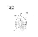
図5は、図3の一部分の拡大図である。ステム120と、フランジ130と、ナット140と、シール150とが組み立てられると、シール150の(簡略化のために図3にのみ印が付けられている)外側部分152が、フランジ130とナット140の間に位置決めされる。この構成では、ナット140に加えることができるトルクは比較的低い。
FIG. 5 is an enlarged view of a part of FIG. When the
これらのゴムフラップ158は、フランジ130の内側で、フランジがねじを有さない可能性のある部分内で、ステム120を覆うためのものである。図3で、ステム120が軸160に沿って右から左に前進するとき、このゴムフラップは、同じ方向に移動する傾向があり、切り刻まれる可能性がある。
These
軸160に沿ってステム120が数回移動した後、シール150のゴム部分154が切り刻まれ、この切り刻みがガス漏れを防止するシール150の能力を大幅に低下させることが観察されている。したがって、このシール150はしばしば交換しなければならない。このシールの交換は、圧縮機の少なくとも部分的な分解を必要とし、したがってそれは、ガス処理設備の不稼動時間に追加される。
It has been observed that the
このシール150が設計パラメータで動作する場合でさえ、相当なトルクをナット140に加えることができたときでも静合が確保されない場合、このシールの有効性は、天然ガスが大きな割合の硫化水素を有するとき、安全に使用するのには低すぎるものとなる。
Even when the
したがって、前述の問題点および欠点を回避するシステムおよび方法を提供することは望ましいであろう。 Accordingly, it would be desirable to provide a system and method that avoids the aforementioned problems and drawbacks.
例示的な一実施形態によれば、ねじ継手は、フランジと、ナットと、可撓性シールとを含む。このフランジは、内側表面上のねじと座ぐり穴とを有し、このねじはステムの外側表面上のねじに対する相補的な形状を有する。フランジは、ステムが回転によってフランジを貫通して移動できるように構成される。この例示的な実施形態のナットは、内側表面上のねじと溝とを有し、ナットのねじは、ステムの外側表面上のねじに対する相補的な形状を有する。このナットは、回転によってステムに対して移動するように構成される。この例示的な実施形態の可撓性シールは、内側表面上にねじを有し、可撓性シールのねじは、ステムの外側表面上のねじに対する相補的な形状を有する。この可撓性シールは、回転によってステムに対して移動するように構成され、フランジ内の座ぐり穴を充填するように構成された第1の部分と、ナットの溝を充填するように構成された第2の部分とを有する。 According to one exemplary embodiment, the threaded joint includes a flange, a nut, and a flexible seal. The flange has a screw on the inner surface and a counterbore, and the screw has a complementary shape to the screw on the outer surface of the stem. The flange is configured such that the stem can move through the flange by rotation. The nut of this exemplary embodiment has a screw and groove on the inner surface, and the nut screw has a complementary shape to the screw on the outer surface of the stem. The nut is configured to move relative to the stem upon rotation. The flexible seal of this exemplary embodiment has a screw on the inner surface, and the flexible seal screw has a complementary shape to the screw on the outer surface of the stem. The flexible seal is configured to move relative to the stem upon rotation, and is configured to fill a nut groove and a first portion configured to fill a counterbore in the flange. A second portion.
別の例示的な実施形態によれば、ねじ継手を封止する方法が提供される。この方法は、外側表面上に第1のねじを有するステムを、内側表面上に第2のねじを有するフランジを貫通して移動させるステップを含み、この第2のねじは第1のねじに対する相補的な形状を有する。この方法は、内側表面上に第3のねじを有する可撓性シールを、可撓性シールの第1の部分がフランジ内の座ぐり穴を充填するまで、ステムに沿って、フランジに向かって移動させるステップも含み、この第3のねじは第1のねじに対する相補的な形状を有する。さらにこの方法は、内側表面上に第4のねじを有するナットを、可撓性シールの第2の部分がナットの内側の溝を充填するまで、ステムに沿って、フランジに向かって移動させるステップを含み、この第4のねじは第1のねじに対する相補的な形状を有する。この方法はさらに、可撓性シールの第2の部分がナットの内側の溝を充填した後、ナットに所定のトルクを加えるステップを含む。 According to another exemplary embodiment, a method for sealing a threaded joint is provided. The method includes moving a stem having a first screw on the outer surface through a flange having a second screw on the inner surface, the second screw being complementary to the first screw. It has a typical shape. The method places a flexible seal having a third screw on the inner surface along the stem and toward the flange until the first portion of the flexible seal fills a counterbore in the flange. Including a step of moving, the third screw having a complementary shape to the first screw. The method further includes moving a nut having a fourth screw on the inner surface along the stem toward the flange until the second portion of the flexible seal fills the groove inside the nut. And the fourth screw has a complementary shape to the first screw. The method further includes applying a predetermined torque to the nut after the second portion of the flexible seal fills the groove inside the nut.
別の実施形態によれば、ねじ継手を封止するためのツーピースのシールナットは、ナットおよび可撓性シールを含む。このナットは、ステムを取り囲み、ステムに沿って移動するように構成され、溝を有する。可撓性シールは、ステムを保持するフランジの内側で、ステムを取り囲み、ステムに沿って移動するように構成され、フランジ内の座ぐり穴を充填するように構成された第1の部分と、ナット内の溝を充填するように構成された第2の部分とを有するように構成される。 According to another embodiment, a two-piece seal nut for sealing a threaded joint includes a nut and a flexible seal. The nut surrounds the stem and is configured to move along the stem and has a groove. A flexible seal, on the inside of the flange holding the stem, surrounding the stem and configured to move along the stem; and a first portion configured to fill a counterbore in the flange; And a second portion configured to fill a groove in the nut.
別の実施形態によれば、可撓性シールは、第1の部分と第2の部分を含む。この第1の部分は、ねじ切りされたステムを保持するフランジ内の座ぐり穴を充填するように構成される。第2の部分はナットの溝を充填するように構成され、第1の部分の直径と異なる直径を有する。これらの第1の部分および第2の部分は、ねじ切りされたステムに沿って可撓性シールが移動できるように構成された、内側孔の表面上のねじを有し、可撓性シールのこのねじは、ねじ切りされたステムの外側表面上のねじに対する相補的な形状を有する。 According to another embodiment, the flexible seal includes a first portion and a second portion. This first portion is configured to fill a counterbore in the flange that holds the threaded stem. The second part is configured to fill the nut groove and has a diameter different from the diameter of the first part. These first and second portions have threads on the surface of the inner bore configured to allow movement of the flexible seal along the threaded stem and this of the flexible seal. The screw has a complementary shape to the screw on the outer surface of the threaded stem.
本明細書に組み込まれ、本明細書の一部を構成する添付の図面は、1つまたは複数の実施形態を図示し、本説明と一緒にこれらの実施形態を明らかにする。 The accompanying drawings, which are incorporated in and constitute a part of this specification, illustrate one or more embodiments and, together with the description, reveal these embodiments.
例示的な実施形態の以下の説明では、添付の図面を参照する。異なる図面内の同じ参照番号は、同じまたは同様な要素を特定する。以下の詳細な説明は、本発明を限定しない。その代わりに、本発明の範囲は、添付の特許請求の範囲によって定義される。簡単にするために、以下の実施形態は圧縮機のねじ継手の用語および構造に関して論じられる。しかし、次に論じる実施形態は圧縮機のねじ継手に限定されず、漏れのないねじ継手を形成する必要がある他のシステムにも適用可能である。 In the following description of the exemplary embodiments, reference is made to the accompanying drawings. The same reference numbers in different drawings identify the same or similar elements. The following detailed description does not limit the invention. Instead, the scope of the invention is defined by the appended claims. For simplicity, the following embodiments are discussed in terms of compressor threaded joint terminology and structure. However, the embodiments discussed below are not limited to compressor threaded joints and are applicable to other systems that need to form leak-free threaded joints.
本明細書を通して「一(one)実施形態」または「ある(an)実施形態」についての言及は、ある実施形態と関連して説明される特定の機構、構造、または特徴は、開示される主題の少なくとも1つの実施形態に含まれることを意味する。したがって、本明細書を通して様々な場所で、語句「一実施形態で」または「ある実施形態で」が現れても、必ずしも同じ実施形態を意味しない。さらに、これらの特定の機構、構造または特徴は、1つまたは複数の実施形態で任意の適切な方法で組み合わせることができる。 Reference throughout this specification to “one embodiment” or “an embodiment” refers to a particular feature, structure, or feature described in connection with an embodiment. In at least one embodiment. Thus, the appearances of the phrases “in one embodiment” or “in an embodiment” in various places throughout this specification are not necessarily referring to the same embodiment. Further, these particular features, structures or features may be combined in any suitable manner in one or more embodiments.
図6は、一実施形態によるねじ継手200の分解図である。このねじ継手200は、天然ガスなどの流体の漏れを効果的に防止する。ステム220が高圧容器(例えば、図1のチャンバ10参照)からフランジ230を貫通して出てくる。このステム220は、高圧容器の内側に一端部を、高圧容器の外側に対向する端部を有する。このステム220およびフランジ230の他に、このねじ継手200は、ナット240と可撓性シール250とによって形成されるツーピースのシールナットも含むことができる。ねじ継手200の全ての構成部品は共通の軸260を有する。
FIG. 6 is an exploded view of a threaded joint 200 according to one embodiment. The threaded joint 200 effectively prevents leakage of fluid such as natural gas. A
このフランジ230、ナット240および可撓性シール250は、それぞれのそれらの内側表面の少なくとも一部分にねじを有する。これらのねじは、ステム220の外側表面のねじに対する相補的な形状を有する。
This
ナット240は、フランジ230に向かって組み立てられる端部上に内側の溝270を有する。フランジ230は、ナット240に向かって組み立てられる一端部に、フランジの内側の座ぐり穴280を有する。溝270の直径は、座ぐり穴280の直径より大きくすることができる。
The
可撓性シール250は、フランジ230の座ぐり穴280の内側に部分的に嵌合し、ナット240の溝270の内側に部分的に嵌合するように構成される。具体的にはこの可撓性シール250は、座ぐり穴280を充填するような形状にされる第1の部分290と、溝270を充填するような形状にされる第2の部分300とを有する。この第1の部分290および第2の部分300は、異なる直径を有することができる。一応用例では、可撓性シール250のこの第1の部分290は、第2の部分300の外径より小さな外径を有する。
The
この可撓性シール250は中央孔を有し、ねじ310がこの中央孔の周りの内側表面上に配置される。このねじ310は、ステム220上のねじに対する相補的な形状を有する。したがって、この可撓性シール250は、可撓性シール250および/またはステム220が軸260の周りを回転するとき、ステム220に対して軸260に沿って移動するように構成される。
The
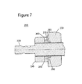
ねじ継手200の横断面を図7に示す。ステム220は、軸260に沿ってフランジ230およびナット240を通り抜ける。可撓性シール250は、ステム220の周りで、フランジ230とナット240との間に載置される。この可撓性シール250は、フランジ230の座ぐり穴280と、ナット240の溝270の内側に嵌合する。
A cross section of the threaded joint 200 is shown in FIG.
一応用例では、この可撓性シール250は、永久変形を受ける前にかなりの量の応力に耐えることができる材料から作ることができる。例えば、この可撓性シール250は全体を、ゴムまたはゴムのような弾力性および圧縮性を有する別のポリマーから作ることができる。この可撓性シール250用に使用される材料は、硫化水素(H2S)に起因する腐蝕に対し耐性があることもできる。
In one application, the
ナット240および可撓性シール250は、ツーピースのシールナットを形成し、それにより、ねじ継手200がそこを介した流体の漏れを防止できるようになる。
例えばガス処理設備内にこのねじ継手200を組み立てるために、軸260に沿って移動しフランジ230を貫通するように、ステム220が最初に回転される。次いで可撓性シール250が、可撓性シール250の第1の部分290がフランジ230の内側の座ぐり穴280の容積を充填するまで、ステム220上を前進するように回転される。一応用例では、この第1の部分290は、第2の部分300の直径より小さな外径を有する。
For example, to assemble this threaded joint 200 in a gas processing facility, the
次いでナット240が、可撓性シール250の第2の部分300がナット240の溝270を充填するまで、ステム220上をフランジ230に向かって前進するように回転される。
The
次いで、所定のトルク値を有するトルクがナット240に加えられる。例えば、50.8mm(2インチ)の直径を有するステムに対して、1.085KN・m(800フィートポンド)のトルクが加えられ、63.5mm(2.5インチ)の直径を有するステムに対して、1.356KN・m(1000フィートポンド)のトルクが加えられる。
A torque having a predetermined torque value is then applied to the
ナット240は、実質的な長方形の側面から作られる、軸260に対して直角な横断面で6角形を形成する外側表面を有することができる。しかし、ナット240の外側表面はこの6角形の形状に限定されず、他の形状も有することができる。ナット240は金属または適切な代替品と考えられる他の複合材料から作ることができる。
The
一実施形態ではこの可撓性シール250は、約75のデュロメータ値を有するポリマーから作ることができる。この可撓性シール250の長さは、この可撓性シールが所定のトルクを支持するのが可能であるように選ぶことができる。例えば、この長さは12.7mm(0.5インチ)であることができる。
In one embodiment, the
ナット240にトルクが加えられるとき、この可撓性シール250は、ステム220の周りに、かつ内側の溝270および座ぐり穴280の内側にしっかりと嵌合するように締め付けられる。溝270および座ぐり穴280の存在は、ナット240とフランジ230の外面間の可撓性シール250の変形を防止するので有利である。したがって、ナット240と可撓性シール250によって形成される、ねじ継手を封止するこのツーピースのナットは、そこを通る流体の漏れを防止する能力を高める。
When torque is applied to the
その上、可撓性シール250のために使用されるねじ310および特徴的な材料は、ステム220が回転し軸260に沿って移動するとき、ツーピースのねじ切りされたナットが、切り刻まれることによる損傷を受け難くする。
In addition, the
様々な実施形態による、ねじ継手の構成部品の幾何学的形状は、以下の機構、すなわち(a)溝を有するナット、(b)座ぐり穴を有するフランジ、(c)ナットの溝内に嵌合する第1の部分と、フランジの座ぐり穴内に嵌合する第2の部分とを有する可撓性シール、(d)ねじを有する、可撓性シールの内側表面、のうちの少なくともいくつかを有する。これらの機構は、別々にまたは組み合わせで、そこを通る漏れを防止するのに既存のねじ継手より良好なねじ継手になる。座ぐり穴、溝および可撓性シールの寸法は、ナットに加えられる十分に高いトルクを許容するように選択される。可撓性シール用に適切な特性を有する材料を選ぶことによって、切り刻まれるのを遅らせ、または防止する。さらに、フランジ230およびナット240の外面に露出される可撓性シール250を持たないことによって、ナット240およびフランジ230に加えられるトルクは、可撓性シール250を損傷させることを少なくすることができる。
According to various embodiments, the geometry of the threaded joint components may include the following mechanisms: (a) a nut with a groove, (b) a flange with a counterbore, (c) a fit in the groove of the nut. At least some of a flexible seal having a mating first portion and a second portion that fits into a counterbore of the flange; (d) an inner surface of the flexible seal having a screw Have These mechanisms, either separately or in combination, make a threaded joint better than existing threaded joints to prevent leakage therethrough. Counterbore, groove and flexible seal dimensions are selected to allow a sufficiently high torque applied to the nut. Delay or prevent chopping by choosing a material with suitable properties for the flexible seal. Further, by not having the
図8は、ある実施形態による、ねじ継手を封止する方法の流れ線図を示す。S810で、この方法は、外側表面上に第1のねじを有するステム(例えば、220)を、内側表面上に第2のねじを有するフランジ(例えば、230)を貫通して移動させるステップを含む。この第2のねじは第1のねじに対する相補的な形状を有する。 FIG. 8 shows a flow diagram of a method for sealing a threaded joint, according to an embodiment. At S810, the method includes moving a stem (eg, 220) having a first screw on the outer surface through a flange (eg, 230) having a second screw on the inner surface. . The second screw has a complementary shape to the first screw.
さらにS820で、この方法は、内側表面上に第3のねじを有する可撓性シール(例えば、250)を、可撓性シール(例えば、250)の第1の部分(例えば、290)がフランジ(例えば、230)内の座ぐり穴(例えば、280)を充填するまで、ステム(例えば、220)上を、フランジ(例えば、230)に向かって移動させるステップを含む。この第3のねじは第1のねじに対する相補的な形状を有する。 Further at S820, the method includes a flexible seal (eg, 250) having a third screw on the inner surface, and a first portion (eg, 290) of the flexible seal (eg, 250) is flanged. Moving over the stem (eg, 220) toward the flange (eg, 230) until the counterbore (eg, 280) in (eg, 230) is filled. This third screw has a complementary shape to the first screw.
S830で、この方法は、内側表面上に第4のねじを有するナット(例えば、240)を、可撓性シール(例えば、250)の第2の部分(例えば、300)がナット(例えば、240)の内側の溝(例えば、270)を充填するまで、ステム(例えば、220)上を、フランジ(例えば、230)に向かって移動させるステップを含む。第4のねじは第1のねじに対する相補的形状を有する。 At S830, the method includes a nut (eg, 240) having a fourth screw on the inner surface and a second portion (eg, 300) of the flexible seal (eg, 250) is a nut (eg, 240). ) On the stem (eg, 220) toward the flange (eg, 230) until the inner groove (eg, 270) is filled. The fourth screw has a complementary shape to the first screw.
最後にS840で、この方法は、可撓性シール(例えば、250)の第2の部分(例えば、300)がナット(例えば、240)の内側の溝(例えば、270)を充填した後、ナット(例えば、240)に所定のトルクを加えるステップを含む。 Finally, at S840, the method includes the step after the second portion (eg, 300) of the flexible seal (eg, 250) fills the groove (eg, 270) inside the nut (eg, 240). Applying a predetermined torque to (e.g., 240).
開示される例示的な実施形態は、従来型の方法、ねじ継手および可撓性シールより長いライフサイクルを有し、より良好に漏れを防止する、ねじ継手を封止する方法と、ねじ継手と、可撓性シールとを提供する。この説明は本発明を限定するためのものではないことを理解すべきである。それどころか、これらの例示的な実施形態は、添付の特許請求の範囲によって定義される本発明の趣旨および範囲に含まれる代替、改変および均等物を包含するためのものである。さらに、例示的な実施形態の詳細な説明では、特許請求される発明の包括的な理解を与えるように多数の特定の詳細が記載されている。しかし当業者は、様々な実施形態をそのような特定の詳細なしで実施できることを理解するであろう。 Exemplary embodiments disclosed include a method of sealing a threaded joint, having a longer life cycle than a conventional method, threaded joint and flexible seal, and better preventing leakage, and a threaded joint A flexible seal. It should be understood that this description is not intended to limit the invention. On the contrary, these exemplary embodiments are intended to embrace alternatives, modifications and equivalents that fall within the spirit and scope of the invention as defined by the appended claims. Furthermore, in the detailed description of the exemplary embodiments, numerous specific details are set forth in order to provide a comprehensive understanding of the claimed invention. However, one of ordinary skill in the art appreciates that various embodiments can be practiced without such specific details.
本例示的な実施形態の機構および要素がこれらの実施形態で特定の組み合わせで説明されているけれども、各機構または要素は、これらの実施形態の他の機構および要素なしで単独で使用することができ、または本明細書で開示される他の機構および要素との様々な組み合わせで、または組み合わせなしで使用することができる。 Although the mechanisms and elements of the present exemplary embodiments are described in specific combinations in these embodiments, each mechanism or element can be used alone without the other mechanisms and elements in these embodiments. Can be used, or in various combinations with or without other mechanisms and elements disclosed herein.
本書は、任意の装置またはシステムを作製および使用し、任意の組み入れられた方法を実施することを含めて、当業者なら誰でも本主題を実施することができるように、開示されている主題の例を使用している。本主題の特許性のある範囲は特許請求の範囲によって定義され、当業者に思い付く他の例も含むことができる。そのような他の例は、特許請求の範囲の範囲内にあるものとする。 This document describes the disclosed subject matter so that anyone skilled in the art can practice the subject matter, including making and using any device or system and performing any incorporated methods. An example is used. The patentable scope of the subject matter is defined by the claims, and may include other examples that occur to those skilled in the art. Such other examples are intended to be within the scope of the claims.
10 チャンバ
200 ねじ継手
220 ステム
230 フランジ
240 ナット
250 可撓性シール
260 軸
270 溝
280 座ぐり穴
290 第1の部分
300 第2の部分
310 ねじ
10
Claims (15)
前記ステム(220)の前記外側表面上のねじに対する相補的な形状を有する内側表面上のねじと溝(270)とを有するナット(240)であって、回転によって前記ステム(220)に対して移動するように構成されたナット(240)と、
前記ステム(220)の前記外側表面上のねじに対する相補的な形状を有する内側表面上のねじを有する可撓性シール(250)であって、回転によって前記ステム(220)に対して移動するように構成されており、前記フランジ(230)内の前記座ぐり穴(280)を充填するように構成された第1の部分(290)と、前記ナット(240)の前記溝(270)を充填するように構成された第2の部分(300)とを有する可撓性シール(250)と
を備える、ねじ継手(200)。 A flange (230) having a screw on the inner surface and a counterbore (280) having a complementary shape to a screw on the outer surface of the stem (220), wherein the stem (220) is flanged by rotation ( 230) a flange (230) configured to be movable through
A nut (240) having a screw on the inner surface and a groove (270) having a complementary shape to the screw on the outer surface of the stem (220) relative to the stem (220) by rotation. A nut (240) configured to move;
A flexible seal (250) having a screw on the inner surface having a complementary shape to the screw on the outer surface of the stem (220), such that the stem (220) moves relative to the stem (220) by rotation. A first portion (290) configured to fill the counterbore (280) in the flange (230) and the groove (270) of the nut (240) A threaded joint (200) comprising: a flexible seal (250) having a second portion (300) configured to:
内側表面上に第3のねじを有する可撓性シール(250)を、前記可撓性シール(250)の第1の部分(290)が前記フランジ(230)内の座ぐり穴(280)を充填するまで、回転によって、前記ステム(220)に沿って、前記フランジ(230)に向かって移動させるステップ(S820)であって、前記第3のねじが前記第1のねじに対する相補的な形状を有するステップと、
内側表面上に第4のねじを有するナット(240)を、前記可撓性シール(250)の第2の部分(300)が前記ナット(240)の内側の溝(270)を充填するまで、回転によって、前記ステム(220)に沿って、前記フランジ(230)に向かって移動させるステップ(S830)であって、前記第4のねじが前記第1のねじに対する相補的な形状を有するステップと、
前記可撓性シール(250)の前記第2の部分(300)が前記ナット(240)の内側の前記溝(270)を充填した後、前記ナット(240)に所定のトルクを加えるステップ(S840)とを含む、ねじ継手を封止する方法。 Moving the stem (220) having a first screw on the outer surface through a flange (230) having a second screw on the inner surface by rotation (S810), the second A screw having a complementary shape to the first screw;
A flexible seal (250) having a third screw on the inner surface, and a first portion (290) of the flexible seal (250) has a counterbore (280) in the flange (230). Moving (S820) along the stem (220) toward the flange (230) by rotation until filling, wherein the third screw is complementary to the first screw. A step comprising:
Nut (240) having a fourth screw on the inner surface until the second portion (300) of the flexible seal (250) fills the groove (270) inside the nut (240). Rotating (S830) along the stem (220) toward the flange (230) by rotation, wherein the fourth screw has a complementary shape to the first screw; ,
After the second part (300) of the flexible seal (250) fills the groove (270) inside the nut (240), a predetermined torque is applied to the nut (240) (S840). A method of sealing a threaded joint.
前記ステム(220)を取り囲み、前記ステム(220)に沿って移動するように構成されており、溝(270)を有するナット(240)と、
前記ステム(220)を保持するフランジ(230)の内側で、前記ステム(220)を取り囲み、前記ステム(220)に沿って移動するように構成されており、前記フランジ内の座ぐり穴(280)を充填するように構成された第1の部分(290)と、前記ナット(240)内の前記溝(270)を充填するように構成された第2の部分(300)とを有するように構成された可撓性シール(250)とを備える、ツーピースのシールナット。 A two-piece seal nut for sealing a threaded joint comprising a stem (220) having threads on its outer surface,
A nut (240) surrounding the stem (220) and configured to move along the stem (220) and having a groove (270);
Inside the flange (230) that holds the stem (220), the stem (220) is surrounded and configured to move along the stem (220). ) And a second portion (300) configured to fill the groove (270) in the nut (240). A two-piece seal nut comprising a configured flexible seal (250).
ナット(240)の溝(270)を充填するように構成されており、前記第1の部分(290)の直径と異なる直径を有する第2の部分(300)とを備え、
前記第1の部分(290)と前記第2の部分(300)が、内側孔の表面上に前記可撓性シール(250)が前記ねじ切りされたステム(220)に沿って移動できるように構成されたねじを有し、前記可撓性シール(250)の前記ねじが前記ねじ切りされたステム(220)の外側表面上のねじに対する相補的な形状を有する、可撓性シール(250)。 A first portion (290) configured to fill a counterbore (280) in the flange (230) holding the threaded stem (220);
A second portion (300) configured to fill the groove (270) of the nut (240) and having a diameter different from the diameter of the first portion (290);
The first portion (290) and the second portion (300) are configured such that the flexible seal (250) can move along the threaded stem (220) over the surface of the inner bore. A flexible seal (250), wherein the screw of the flexible seal (250) has a complementary shape to a screw on an outer surface of the threaded stem (220).
Applications Claiming Priority (2)
| Application Number | Priority Date | Filing Date | Title |
|---|---|---|---|
| US12/847,254 US8523503B2 (en) | 2010-07-30 | 2010-07-30 | Threaded joint and method of sealing a threaded joint |
| US12/847,254 | 2010-07-30 |
Publications (2)
| Publication Number | Publication Date |
|---|---|
| JP2012031994A true JP2012031994A (en) | 2012-02-16 |
| JP2012031994A5 JP2012031994A5 (en) | 2014-09-04 |
Family
ID=44532633
Family Applications (1)
| Application Number | Title | Priority Date | Filing Date |
|---|---|---|---|
| JP2011160399A Pending JP2012031994A (en) | 2010-07-30 | 2011-07-22 | Threaded joint and method of sealing threaded joint |
Country Status (6)
| Country | Link |
|---|---|
| US (1) | US8523503B2 (en) |
| EP (1) | EP2412990B1 (en) |
| JP (1) | JP2012031994A (en) |
| CN (1) | CN102345661B (en) |
| CA (1) | CA2746299C (en) |
| RU (1) | RU2564176C2 (en) |
Families Citing this family (8)
| Publication number | Priority date | Publication date | Assignee | Title |
|---|---|---|---|---|
| US20140115868A1 (en) * | 2012-10-29 | 2014-05-01 | Gregory Ruhlander | Coupling System to Reduce Vibration |
| CN103527607A (en) * | 2013-10-24 | 2014-01-22 | 昆山市联昆热压板有限公司 | Nut |
| WO2016019977A1 (en) * | 2014-08-05 | 2016-02-11 | Nokia Solutions And Networks Oy | Signaling physical cell identifier problems |
| US20160208840A1 (en) * | 2015-01-16 | 2016-07-21 | Matthew Neber | Fastener With Removable Head End |
| CN109424803A (en) * | 2017-08-31 | 2019-03-05 | 杭州三花研究院有限公司 | Pipe joint component and heat pump system |
| DE202018106798U1 (en) * | 2018-11-29 | 2020-03-04 | Conta-Clip Verbindungstechnik Gmbh | Cable gland |
| FR3089579B1 (en) * | 2018-12-07 | 2021-07-09 | Addup | SLOTTED NUT FOR SELECTIVE ADDITIVE MANUFACTURING EQUIPMENT |
| CN113847486A (en) * | 2021-09-30 | 2021-12-28 | 中国船舶重工集团公司第七二四研究所 | Pipeline connection structure that prevention of seepage vibration pine takes off |
Citations (5)
| Publication number | Priority date | Publication date | Assignee | Title |
|---|---|---|---|---|
| JPS52123275U (en) * | 1976-03-16 | 1977-09-19 | ||
| JPS56166251A (en) * | 1980-04-23 | 1981-12-21 | Du Pont | Fluoroelastomer composition |
| JPS6047915U (en) * | 1983-09-09 | 1985-04-04 | 自動車機器株式会社 | Sealing screw device |
| JPH07151233A (en) * | 1993-09-02 | 1995-06-13 | Eaton Corp | Holding type sealing device |
| US20070052229A1 (en) * | 2005-09-02 | 2007-03-08 | Weisbond Bradley K | Double containment pressure termination fitting for dissimilar materials |
Family Cites Families (37)
| Publication number | Priority date | Publication date | Assignee | Title |
|---|---|---|---|---|
| US3123245A (en) * | 1964-03-03 | Dumpis | ||
| US652530A (en) * | 1899-09-19 | 1900-06-26 | George B Wix | Nut-lock. |
| US646898A (en) * | 1900-01-17 | 1900-04-03 | Edward L Bill | Nut-lock. |
| US659215A (en) * | 1900-07-02 | 1900-10-09 | John L Doelp | Nut-lock. |
| US1607273A (en) * | 1923-12-21 | 1926-11-16 | French & Hecht | Means for the attachment of parts or members to each other |
| US1607274A (en) * | 1924-10-10 | 1926-11-16 | Firm Of French & Hecht | Means for attaching parts or members together |
| US2333388A (en) * | 1942-03-13 | 1943-11-02 | Illinois Tool Works | Fastener device |
| US2360531A (en) | 1942-10-09 | 1944-10-17 | Vincent L Kruszynski | Lock nut |
| US2360631A (en) * | 1942-12-09 | 1944-10-17 | Standard Oil Dev Co | Lubricant |
| US2502642A (en) | 1945-10-27 | 1950-04-04 | Currlin Bernard | Lock nut |
| US3259404A (en) | 1963-10-23 | 1966-07-05 | Parker Hannifin Corp | Sealed joint and gasket therefor |
| US3181899A (en) * | 1964-01-27 | 1965-05-04 | Corning Glass Works | Assembly for connecting pipe to an apertured tank |
| US3399589A (en) * | 1965-12-29 | 1968-09-03 | Lamson & Sessions Co | Sealing fastener |
| GB1172885A (en) * | 1966-05-20 | 1969-12-03 | Wirth Alfred & Co Kg | Improvements relating to Pumps |
| US3596931A (en) | 1969-02-10 | 1971-08-03 | Armor Cote Corp | Seal for lined pipe |
| GB1347783A (en) | 1971-06-25 | 1974-02-27 | Refac Technology Dev Corp | Fastening devices |
| SE363384B (en) * | 1972-06-29 | 1974-01-14 | Aby Ab | |
| US4046052A (en) * | 1976-10-14 | 1977-09-06 | Solitron Devices, Inc. | Torque limiting RF connector |
| US4489963A (en) | 1982-04-13 | 1984-12-25 | Otis Engineering Corporation | Pipe joint |
| US4458925A (en) | 1983-05-19 | 1984-07-10 | Otis Engineering Corporation | Pipe joint |
| US4696498A (en) | 1986-10-29 | 1987-09-29 | Quanex Corporation | Tubular connection |
| US5011162A (en) * | 1989-07-20 | 1991-04-30 | Parker Hannifin Corporation | Bi-lobed sealing element and retainer |
| FR2657938B1 (en) * | 1990-02-05 | 1992-05-15 | Simmonds Sa | IMPROVED WATERPROOF CONNECTION FOR CONDUITS OF TRANSPORT OF ANY FLUIDS. |
| US5083821A (en) | 1990-12-05 | 1992-01-28 | Itt Corporation | Extreme temperature thread sealing method and apparatus |
| US5513859A (en) * | 1992-11-12 | 1996-05-07 | Avl Medical Instruments Ag | Sealing element |
| US5628517A (en) | 1993-06-01 | 1997-05-13 | Florida Atlantic University | Contracting/expanding self-sealing cryogenic tube seals |
| US5405176A (en) | 1994-02-15 | 1995-04-11 | Mcdonnell Douglas Corporation | High pressure mechanical seal |
| US5692865A (en) * | 1996-06-14 | 1997-12-02 | Textron Inc. | Quick release fastener system |
| US6098727A (en) | 1998-03-05 | 2000-08-08 | Halliburton Energy Services, Inc. | Electrically insulating gap subassembly for downhole electromagnetic transmission |
| US6254104B1 (en) * | 1999-04-27 | 2001-07-03 | Precision Valve Corporation | Gasket for an aerosol valve stem |
| ATE360171T1 (en) * | 1999-09-13 | 2007-05-15 | Swagelok Co | PIPE CONNECTION WITH INDICATOR |
| US6811189B1 (en) | 2000-10-04 | 2004-11-02 | Grant Prideco, L.P. | Corrosion seal for threaded connections |
| US6866305B2 (en) | 2002-07-03 | 2005-03-15 | Spears Manufacturing Co. | Pipe fitting having strengthened starter threads |
| US6883807B2 (en) * | 2002-09-13 | 2005-04-26 | Seimens Westinghouse Power Corporation | Multidirectional turbine shim seal |
| EP1760381A1 (en) | 2005-09-06 | 2007-03-07 | Siemens Aktiengesellschaft | Threaded fitting connection as well as fitting and axial sealing for such a threaded fitting connection and use of a threaded fitting connection |
| RU2325581C2 (en) * | 2006-02-03 | 2008-05-27 | Зао "Нпп Тормо" | Pressure-tight detachable joint for tubing |
| US7946440B2 (en) | 2007-11-13 | 2011-05-24 | Kvt Koenig, Llc | Two-piece expandable sealing plug |
-
2010
- 2010-07-30 US US12/847,254 patent/US8523503B2/en active Active
-
2011
- 2011-07-14 CA CA2746299A patent/CA2746299C/en active Active
- 2011-07-22 JP JP2011160399A patent/JP2012031994A/en active Pending
- 2011-07-25 EP EP11175138.4A patent/EP2412990B1/en active Active
- 2011-07-28 RU RU2011131503/06A patent/RU2564176C2/en active
- 2011-07-29 CN CN201110224463.2A patent/CN102345661B/en active Active
Patent Citations (5)
| Publication number | Priority date | Publication date | Assignee | Title |
|---|---|---|---|---|
| JPS52123275U (en) * | 1976-03-16 | 1977-09-19 | ||
| JPS56166251A (en) * | 1980-04-23 | 1981-12-21 | Du Pont | Fluoroelastomer composition |
| JPS6047915U (en) * | 1983-09-09 | 1985-04-04 | 自動車機器株式会社 | Sealing screw device |
| JPH07151233A (en) * | 1993-09-02 | 1995-06-13 | Eaton Corp | Holding type sealing device |
| US20070052229A1 (en) * | 2005-09-02 | 2007-03-08 | Weisbond Bradley K | Double containment pressure termination fitting for dissimilar materials |
Also Published As
| Publication number | Publication date |
|---|---|
| EP2412990A2 (en) | 2012-02-01 |
| CA2746299C (en) | 2019-01-15 |
| CN102345661B (en) | 2016-12-07 |
| CN102345661A (en) | 2012-02-08 |
| CA2746299A1 (en) | 2012-01-30 |
| EP2412990A3 (en) | 2013-03-20 |
| RU2011131503A (en) | 2013-02-10 |
| RU2564176C2 (en) | 2015-09-27 |
| US20120027539A1 (en) | 2012-02-02 |
| US8523503B2 (en) | 2013-09-03 |
| EP2412990B1 (en) | 2016-09-14 |
Similar Documents
| Publication | Publication Date | Title |
|---|---|---|
| JP2012031994A (en) | Threaded joint and method of sealing threaded joint | |
| CN103244696A (en) | External-pressure type bellows globe valve with non-rotating valve rod | |
| CN206369047U (en) | A kind of material filling type Pipe leakage stopper | |
| TWM453066U (en) | Filler assembly of valve | |
| CN203442144U (en) | External-pressure type bellows stop valve with non-rotating valve rod | |
| KR20130029420A (en) | Blocking device of pipe leak | |
| CN105673992B (en) | A kind of Pipe leakage stopper for including axial packing seal | |
| GB2484338A (en) | Valve seal | |
| CN108194723A (en) | It is axially forced to formula tube joint assembly | |
| CN204604217U (en) | A kind of stopping transportation pressure changes the device of high compression diameter ball valve | |
| CN207318008U (en) | A kind of sealing device for aircraft conduit seal tightness test | |
| CN105650398B (en) | A kind of plugging device | |
| CN206409772U (en) | Function nut and ferrule-type compression joint | |
| KR200453018Y1 (en) | Protecting tube for preventing leakage of fluid | |
| RU2418231C1 (en) | Elastic casing for pressure tight pipeline shutdown | |
| CN207094047U (en) | Novel threaded plug | |
| CN104295795A (en) | High-voltage-resisting double-sealing corrugated pipe stop valve for nuclear power | |
| CN206600518U (en) | A kind of stop valve of sealing structure of rock | |
| JP2010088258A (en) | Sealing degree improving method for compression fluid sealing device, and compression fluid sealing device | |
| CN106917911A (en) | A kind of stop valve of sealing structure of rock | |
| RU102742U1 (en) | ELASTIC CASE FOR SEALING PIPELINES | |
| CN205078906U (en) | Novel ball valve | |
| WO2018152947A1 (en) | Pneumatic fluorine-lined corrugated pipe single-seat regulating valve | |
| KR101169398B1 (en) | Valve with sealing device | |
| CN204512717U (en) | A kind of wide scope flexible pipe connector |
Legal Events
| Date | Code | Title | Description |
|---|---|---|---|
| A521 | Request for written amendment filed |
Free format text: JAPANESE INTERMEDIATE CODE: A523 Effective date: 20140716 |
|
| A621 | Written request for application examination |
Free format text: JAPANESE INTERMEDIATE CODE: A621 Effective date: 20140716 |
|
| A977 | Report on retrieval |
Free format text: JAPANESE INTERMEDIATE CODE: A971007 Effective date: 20150709 |
|
| A131 | Notification of reasons for refusal |
Free format text: JAPANESE INTERMEDIATE CODE: A131 Effective date: 20150714 |
|
| A02 | Decision of refusal |
Free format text: JAPANESE INTERMEDIATE CODE: A02 Effective date: 20151208 |