JP2012007496A - Internal combustion engine control apparatus - Google Patents
Internal combustion engine control apparatus Download PDFInfo
- Publication number
- JP2012007496A JP2012007496A JP2010141794A JP2010141794A JP2012007496A JP 2012007496 A JP2012007496 A JP 2012007496A JP 2010141794 A JP2010141794 A JP 2010141794A JP 2010141794 A JP2010141794 A JP 2010141794A JP 2012007496 A JP2012007496 A JP 2012007496A
- Authority
- JP
- Japan
- Prior art keywords
- air
- fuel ratio
- value
- exhaust gas
- electrode layer
- Prior art date
- Legal status (The legal status is an assumption and is not a legal conclusion. Google has not performed a legal analysis and makes no representation as to the accuracy of the status listed.)
- Pending
Links
Images


Classifications
-
- F—MECHANICAL ENGINEERING; LIGHTING; HEATING; WEAPONS; BLASTING
- F02—COMBUSTION ENGINES; HOT-GAS OR COMBUSTION-PRODUCT ENGINE PLANTS
- F02D—CONTROLLING COMBUSTION ENGINES
- F02D41/00—Electrical control of supply of combustible mixture or its constituents
- F02D41/008—Controlling each cylinder individually
- F02D41/0085—Balancing of cylinder outputs, e.g. speed, torque or air-fuel ratio
-
- F—MECHANICAL ENGINEERING; LIGHTING; HEATING; WEAPONS; BLASTING
- F02—COMBUSTION ENGINES; HOT-GAS OR COMBUSTION-PRODUCT ENGINE PLANTS
- F02D—CONTROLLING COMBUSTION ENGINES
- F02D41/00—Electrical control of supply of combustible mixture or its constituents
- F02D41/02—Circuit arrangements for generating control signals
- F02D41/14—Introducing closed-loop corrections
- F02D41/1438—Introducing closed-loop corrections using means for determining characteristics of the combustion gases; Sensors therefor
- F02D41/1439—Introducing closed-loop corrections using means for determining characteristics of the combustion gases; Sensors therefor characterised by the position of the sensor
- F02D41/1441—Plural sensors
-
- F—MECHANICAL ENGINEERING; LIGHTING; HEATING; WEAPONS; BLASTING
- F02—COMBUSTION ENGINES; HOT-GAS OR COMBUSTION-PRODUCT ENGINE PLANTS
- F02D—CONTROLLING COMBUSTION ENGINES
- F02D41/00—Electrical control of supply of combustible mixture or its constituents
- F02D41/02—Circuit arrangements for generating control signals
- F02D41/14—Introducing closed-loop corrections
- F02D41/1438—Introducing closed-loop corrections using means for determining characteristics of the combustion gases; Sensors therefor
- F02D41/1444—Introducing closed-loop corrections using means for determining characteristics of the combustion gases; Sensors therefor characterised by the characteristics of the combustion gases
- F02D41/1454—Introducing closed-loop corrections using means for determining characteristics of the combustion gases; Sensors therefor characterised by the characteristics of the combustion gases the characteristics being an oxygen content or concentration or the air-fuel ratio
- F02D41/1456—Introducing closed-loop corrections using means for determining characteristics of the combustion gases; Sensors therefor characterised by the characteristics of the combustion gases the characteristics being an oxygen content or concentration or the air-fuel ratio with sensor output signal being linear or quasi-linear with the concentration of oxygen
-
- F—MECHANICAL ENGINEERING; LIGHTING; HEATING; WEAPONS; BLASTING
- F02—COMBUSTION ENGINES; HOT-GAS OR COMBUSTION-PRODUCT ENGINE PLANTS
- F02D—CONTROLLING COMBUSTION ENGINES
- F02D41/00—Electrical control of supply of combustible mixture or its constituents
- F02D41/02—Circuit arrangements for generating control signals
- F02D41/14—Introducing closed-loop corrections
- F02D41/1438—Introducing closed-loop corrections using means for determining characteristics of the combustion gases; Sensors therefor
- F02D41/1473—Introducing closed-loop corrections using means for determining characteristics of the combustion gases; Sensors therefor characterised by the regulation method
- F02D41/1474—Introducing closed-loop corrections using means for determining characteristics of the combustion gases; Sensors therefor characterised by the regulation method by detecting the commutation time of the sensor
Abstract
Description
本発明は、多気筒内燃機関に適用され、各気筒に供給される混合気の空燃比の不均衡(空燃比気筒間インバランス、空燃比気筒間ばらつき、気筒間における空燃比の不均一性)が過度に大きくなったことを判定(監視・検出)することができる「内燃機関の制御装置」に関する。 The present invention is applied to a multi-cylinder internal combustion engine, and an air-fuel ratio imbalance of an air-fuel mixture supplied to each cylinder (air-fuel ratio imbalance among cylinders, air-fuel ratio variation among cylinders, air-fuel ratio non-uniformity among cylinders). The present invention relates to a “control device for an internal combustion engine” capable of determining (monitoring / detecting) that has become excessively large.
従来から、図1に示したように、内燃機関の排気通路に配設された三元触媒(53)と、その三元触媒(53)の上流及び下流にそれぞれ配置された上流側空燃比センサ(67)及び下流側空燃比センサ(68)と、を備えた空燃比制御装置が広く知られている。 Conventionally, as shown in FIG. 1, a three-way catalyst (53) disposed in an exhaust passage of an internal combustion engine, and an upstream air-fuel ratio sensor respectively disposed upstream and downstream of the three-way catalyst (53). An air-fuel ratio control device including (67) and a downstream air-fuel ratio sensor (68) is widely known.
この空燃比制御装置は、機関に供給される混合気の空燃比(機関の空燃比)が理論空燃比と一致するように、上流側空燃比センサの出力値と下流側空燃比センサの出力値とに基いて空燃比フィードバック量を算出し、その空燃比フィードバック量により機関の空燃比をフィードバック制御するようになっている。更に、上流側空燃比センサの出力値のみに基いて「機関の空燃比を理論空燃比に一致させるための空燃比フィードバック量」を算出し、その空燃比フィードバック量により機関の空燃比をフィードバック制御する空燃比制御装置も広く知られている。このような空燃比制御装置において使用される空燃比フィードバック量は、全気筒に対して共通する制御量である。 This air-fuel ratio control device is configured to output the upstream air-fuel ratio sensor output value and the downstream air-fuel ratio sensor output value so that the air-fuel ratio of the air-fuel mixture supplied to the engine (engine air-fuel ratio) matches the stoichiometric air-fuel ratio. The air-fuel ratio feedback amount is calculated based on the above, and the air-fuel ratio of the engine is feedback controlled based on the air-fuel ratio feedback amount. Further, based on only the output value of the upstream air-fuel ratio sensor, the "air-fuel ratio feedback amount for making the engine air-fuel ratio coincide with the stoichiometric air-fuel ratio" is calculated, and the air-fuel ratio of the engine is feedback-controlled by the air-fuel ratio feedback amount. An air-fuel ratio control device is also widely known. The air-fuel ratio feedback amount used in such an air-fuel ratio control device is a control amount common to all cylinders.
ところで、一般に、電子燃料噴射式内燃機関は、各気筒又は各気筒に連通した吸気ポートに少なくとも一つの燃料噴射弁(39)を備えている。従って、ある特定の気筒の燃料噴射弁の特性が「指示された燃料噴射量よりも過大な量の燃料を噴射する特性」となると、その特定の気筒に供給される混合気の空燃比(その特定気筒の空燃比)のみが大きくリッチ側に変化する。即ち、気筒間における空燃比の不均一性(空燃比気筒間ばらつき、空燃比の気筒間インバランス)が大きくなる。換言すると、各気筒に供給される混合気の空燃比である「気筒別空燃比」の間に不均衡が生じる。 Incidentally, in general, an electronic fuel injection internal combustion engine includes at least one fuel injection valve (39) in each cylinder or an intake port communicating with each cylinder. Accordingly, when the characteristic of the fuel injection valve of a specific cylinder becomes “a characteristic of injecting an amount of fuel that is larger than the instructed fuel injection amount”, the air-fuel ratio of the air-fuel mixture supplied to that specific cylinder (that Only the air-fuel ratio of the specific cylinder) greatly changes to the rich side. That is, the non-uniformity of air-fuel ratio among cylinders (air-fuel ratio variation among cylinders, air-fuel ratio imbalance among cylinders) increases. In other words, an imbalance occurs between the “cylinder air-fuel ratio” that is the air-fuel ratio of the air-fuel mixture supplied to each cylinder.
この場合、機関全体に供給される混合気の空燃比の平均は、理論空燃比よりもリッチ側の空燃比となる。従って、全気筒に対して共通する空燃比フィードバック量により、上記特定の気筒の空燃比は理論空燃比に近づけられるようにリーン側へと変更され、同時に、他の気筒の空燃比は理論空燃比から遠ざけられるようにリーン側へと変更させられる。この結果、機関全体に供給される混合気の空燃比の平均は略理論空燃比に一致させられる。 In this case, the average air-fuel ratio of the air-fuel mixture supplied to the entire engine becomes an air-fuel ratio richer than the stoichiometric air-fuel ratio. Therefore, the air-fuel ratio of the specific cylinder is changed to the lean side so that the air-fuel ratio of the specific cylinder approaches the stoichiometric air-fuel ratio by the air-fuel ratio feedback amount common to all the cylinders. It is made to change to the lean side so that it may be kept away from. As a result, the average of the air-fuel ratio of the air-fuel mixture supplied to the entire engine is made substantially coincident with the theoretical air-fuel ratio.
しかしながら、上記特定の気筒の空燃比は依然として理論空燃比よりもリッチ側の空燃比となり、残りの気筒の空燃比は理論空燃比よりもリーン側の空燃比となるから、各気筒における混合気の燃焼状態は完全燃焼とは相違した燃焼状態となる。この結果、各気筒から排出されるエミッションの量(未燃物の量及び/又は窒素酸化物の量)が増大する。このため、機関に供給される混合気の空燃比の平均が理論空燃比であったとしても、増大したエミッションを三元触媒が浄化しきれず、結果として、エミッションが悪化する虞がある。 However, the air-fuel ratio of the specific cylinder is still richer than the stoichiometric air-fuel ratio, and the air-fuel ratios of the remaining cylinders are leaner than the stoichiometric air-fuel ratio. The combustion state becomes a combustion state different from complete combustion. As a result, the amount of emissions discharged from each cylinder (the amount of unburned material and / or the amount of nitrogen oxides) increases. For this reason, even if the average air-fuel ratio of the air-fuel mixture supplied to the engine is the stoichiometric air-fuel ratio, the three-way catalyst cannot completely purify the increased emission, and as a result, the emission may be deteriorated.
従って、気筒間における空燃比の不均一性が過大になっていること(空燃比気筒間インバランス状態が発生していること)を検出し、何らかの対策を講じさせるようにすることはエミッションを悪化させないために重要である。なお、空燃比気筒間インバランスは、特定の気筒の燃料噴射弁の特性が「指示された燃料噴射量よりも過小な量の燃料を噴射する特性」となった場合等にも発生する。 Therefore, detecting that the air-fuel ratio non-uniformity among cylinders is excessive (the air-fuel ratio imbalance condition between cylinders) is detected, and taking some measures will worsen the emissions. It is important not to let it. Note that the air-fuel ratio imbalance among cylinders also occurs when the characteristic of the fuel injection valve of a specific cylinder becomes “a characteristic for injecting an amount of fuel that is less than the instructed fuel injection amount”.
このような空燃比気筒間インバランス状態が発生したか否かを判定する従来の装置の一つは、複数の気筒からの排ガスが集合する排気集合部に配設された空燃比センサ(上記上流側空燃比センサ67)の出力値(出力信号)の軌跡長を取得し、その軌跡長と「機関回転速度に応じて変化する参照値」とを比較し、その比較結果に基いて空燃比気筒間インバランス状態が発生したか否かを判定するようになっている(例えば、特許文献1を参照。) One of the conventional devices for determining whether or not such an air-fuel ratio imbalance state between cylinders has occurred is an air-fuel ratio sensor (the above-mentioned upstream) disposed in an exhaust collecting portion where exhaust gases from a plurality of cylinders collect. The trajectory length of the output value (output signal) of the side air-fuel ratio sensor 67) is acquired, the trajectory length is compared with the “reference value that changes according to the engine speed”, and the air-fuel ratio cylinder is based on the comparison result. It is determined whether or not an imbalance state has occurred (see, for example, Patent Document 1).
なお、本明細書において、空燃比気筒間インバランス状態(過度の空燃比気筒間インバランス状態)は、気筒別空燃比の間の差(気筒別空燃比差)が許容値以上となっている状態、換言すると、未燃物及び/又は窒素酸化物が規定値を超えるような空燃比気筒間インバランス状態を意味する。「空燃比気筒間インバランス状態」が発生したか否かの判定は、単に「空燃比気筒間インバランス判定、又は、インバランス判定」とも称呼される。更に、残りの気筒に供給される混合気の空燃比(例えば、略理論空燃比)から乖離した空燃比の混合気が供給されるようになった気筒は「インバランス気筒」とも称呼される。インバランス気筒に供給される混合気の空燃比は「インバランス気筒の空燃比」とも称呼される。残りの気筒(インバランス気筒以外の気筒)は、「正常気筒」又は「非インバランス気筒」とも称呼される。正常気筒に供給される混合気の空燃比は、「正常気筒の空燃比」又は「非インバランス気筒の空燃比」とも称呼される。 In the present specification, in an air-fuel ratio imbalance state between cylinders (excessive air-fuel ratio imbalance state between cylinders), a difference between cylinder-specific air-fuel ratios (cylinder-specific air-fuel ratio difference) is greater than or equal to an allowable value. State, in other words, an air-fuel ratio imbalance state between cylinders in which unburned matter and / or nitrogen oxide exceeds a specified value. The determination as to whether or not the “air-fuel ratio imbalance state between cylinders” has occurred is also simply referred to as “air-fuel ratio imbalance determination between cylinders or imbalance determination”. Further, a cylinder that is supplied with an air-fuel mixture that deviates from the air-fuel ratio (for example, approximately the stoichiometric air-fuel ratio) of the air-fuel mixture supplied to the remaining cylinders is also referred to as an “imbalance cylinder”. The air-fuel ratio of the air-fuel mixture supplied to the imbalance cylinder is also referred to as “the air-fuel ratio of the imbalance cylinder”. The remaining cylinders (cylinders other than the imbalance cylinder) are also referred to as “normal cylinders” or “non-imbalance cylinders”. The air-fuel ratio of the air-fuel mixture supplied to the normal cylinder is also referred to as “normal cylinder air-fuel ratio” or “non-imbalance cylinder air-fuel ratio”.
加えて、上述した空燃比センサの出力値の軌跡長のように、気筒別空燃比差(インバランス気筒の空燃比と正常気筒の空燃比との差)の絶対値が大きくなることに起因して「空燃比センサが配設された部位を通過する排ガスの空燃比の変動が大きくなるほど大きくなるパラメータ」は「インバランス判定用パラメータ」とも称呼される。このインバランス判定用パラメータは、空燃比センサの出力値に基いて取得される。インバランス判定用パラメータは、インバランス判定を実行するために、インバランス判定用閾値と比較される。 In addition, the absolute value of the cylinder-by-cylinder air-fuel ratio difference (difference between the air-fuel ratio of the imbalance cylinder and the air-fuel ratio of the normal cylinder) increases, as in the locus length of the output value of the air-fuel ratio sensor described above. Thus, “a parameter that increases as the variation in the air-fuel ratio of the exhaust gas that passes through the portion where the air-fuel ratio sensor is disposed” is also referred to as “an imbalance determination parameter”. This imbalance determination parameter is acquired based on the output value of the air-fuel ratio sensor. The imbalance determination parameter is compared with an imbalance determination threshold value in order to execute imbalance determination.
ところで、「インバランス判定用パラメータは、上述した軌跡長の他、空燃比センサの出力値の微分値d(Vabyfs)/dt、空燃比センサの出力値により表される空燃比(検出空燃比abyfs)の微分値d(abyfs)/dt、空燃比センサの出力値の二階微分値d2(Vabyfs)/dt2、及び、検出空燃比abyfsの二階微分値d2(abyfs)/dt2等、種々の値(空燃比変動指標量)に基いて取得され得る。」ことが判明した。 By the way, “the imbalance determination parameter includes the above-mentioned trajectory length, the differential value d (Vabyfs) / dt of the output value of the air-fuel ratio sensor, the air-fuel ratio (detected air-fuel ratio abyfs) expressed by the output value of the air-fuel ratio sensor. ) of the differential value d (abyfs) / dt, the air-fuel ratio of the output value of the sensor second order differential value d 2 (Vabyfs) / dt 2 , and second-order differential value d 2 (abyfs of the detected air-fuel ratio abyfs) / dt 2, etc., It can be obtained based on various values (air-fuel ratio fluctuation index amount) ".
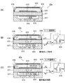
より詳細に述べると、周知の空燃比センサは、例えば図2の(A)に示したように、少なくとも「固体電解質層(671)、排ガス側電極層(672)、大気側電極層(673)及び拡散抵抗層(674)」を含む空燃比検出部を備える。排ガス側電極層(672)は固体電解質層(671)の一面に形成されている。排ガス側電極層(672)は拡散抵抗層(674)により覆われている。排気通路内の排ガスは、拡散抵抗層(674)の外側表面に到達し、拡散抵抗層(674)を通過して排ガス側電極層(672)に到達する。大気側電極層(673)は固体電解質層(671)の他面に形成されている。大気側電極層(673)は大気が導入される大気室(67A)に露呈している。 More specifically, as shown in FIG. 2A, for example, the known air-fuel ratio sensor includes at least a “solid electrolyte layer (671), exhaust gas side electrode layer (672), air side electrode layer (673)”. And a diffusion resistance layer (674) ”. The exhaust gas side electrode layer (672) is formed on one surface of the solid electrolyte layer (671). The exhaust gas side electrode layer (672) is covered with a diffusion resistance layer (674). The exhaust gas in the exhaust passage reaches the outer surface of the diffusion resistance layer (674), passes through the diffusion resistance layer (674), and reaches the exhaust gas side electrode layer (672). The atmosphere side electrode layer (673) is formed on the other surface of the solid electrolyte layer (671). The atmosphere side electrode layer (673) is exposed to the atmosphere chamber (67A) into which the atmosphere is introduced.
図2の(B)及び(C)に示したように、排ガス側電極層(672)と大気側電極層(673)との間には「排ガスの空燃比に応じて変化する限界電流」を発生させるための電圧(空燃比検出用電圧Vp)が印加されている。この空燃比検出用電圧は、一般に、大気側電極層(673)の電位が排ガス側電極層(672)の電位よりも高くなるように印加される。 As shown in FIGS. 2B and 2C, a “limit current that varies depending on the air-fuel ratio of the exhaust gas” is present between the exhaust gas side electrode layer (672) and the atmosphere side electrode layer (673). A voltage for generating (air-fuel ratio detection voltage Vp) is applied. This air-fuel ratio detection voltage is generally applied so that the potential of the atmosphere side electrode layer (673) is higher than the potential of the exhaust gas side electrode layer (672).
図2の(B)に示したように、拡散抵抗層(674)を通過して排ガス側電極層(672)に到達した排ガスに過剰な酸素が含まれているとき(即ち、排ガス側電極層に到達した排ガスの空燃比が理論空燃比よりもリーンであるとき)、その酸素は空燃比検出用電圧と固体電解質層(671)の酸素ポンプ特性とにより酸素イオンとして排ガス側電極層(672)から大気側電極層(673)へと導かれる。 As shown in FIG. 2B, when the exhaust gas that has passed through the diffusion resistance layer (674) and reached the exhaust gas side electrode layer (672) contains excessive oxygen (that is, the exhaust gas side electrode layer). When the air-fuel ratio of the exhaust gas that has reached is leaner than the stoichiometric air-fuel ratio), the oxygen is converted into oxygen ions by the air-fuel ratio detection voltage and the oxygen pump characteristics of the solid electrolyte layer (671), and the exhaust gas side electrode layer (672) To the atmosphere-side electrode layer (673).
これに対し、図2の(C)に示したように、拡散抵抗層(674)を通過して排ガス側電極層(672)に到達した排ガスに過剰な未燃物が含まれているとき(即ち、排ガス側電極層に到達した排ガスの空燃比が理論空燃比よりもリッチであるとき)、大気室(67A)内の酸素は固体電解質層(671)の酸素電池特性により酸素イオンとして大気側電極層(673)から排ガス側電極層(672)へと導かれ、排ガス側電極層(672)の未燃物と反応する。 On the other hand, as shown in FIG. 2C, when the exhaust gas passing through the diffusion resistance layer (674) and reaching the exhaust gas side electrode layer (672) contains excessive unburned matter ( That is, when the air-fuel ratio of the exhaust gas that has reached the exhaust gas-side electrode layer is richer than the stoichiometric air-fuel ratio, oxygen in the atmosphere chamber (67A) is converted to oxygen side as oxygen ions due to the oxygen cell characteristics of the solid electrolyte layer (671). It is led from the electrode layer (673) to the exhaust gas side electrode layer (672), and reacts with unburned substances in the exhaust gas side electrode layer (672).
このような酸素イオンの移動量は、拡散抵抗層(674)の存在により、「拡散抵抗層(674)の外側表面に到達した排ガスの空燃比」に応じた値に制限される。換言すると、酸素イオンの移動により生じる電流は排ガスの空燃比に応じた値(即ち、限界電流Ip)となる(図3を参照。)。 The amount of movement of oxygen ions is limited to a value corresponding to “the air-fuel ratio of exhaust gas that has reached the outer surface of the diffusion resistance layer (674)” due to the presence of the diffusion resistance layer (674). In other words, the current generated by the movement of oxygen ions becomes a value corresponding to the air-fuel ratio of the exhaust gas (that is, the limit current Ip) (see FIG. 3).
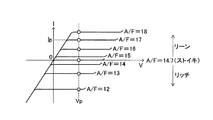
空燃比センサは、この限界電流(排ガス側電極層と大気側電極層との間に空燃比検出用電圧Vpが印加されることにより固体電解質層を流れる電流)に基いて「空燃比センサが配設された部位を通過する排ガスの空燃比」に応じた出力値Vabyfsを出力する。この出力値Vabyfsは、一般には、予め求められている「出力値Vabyfsと空燃比との図4に示した関係」に基いて検出空燃比abyfsに変換される。図4から理解されるように、出力値Vabyfsと検出空燃比abyfsとは実質的に比例している。 The air-fuel ratio sensor is based on this limit current (current flowing through the solid electrolyte layer when the air-fuel ratio detection voltage Vp is applied between the exhaust gas side electrode layer and the atmosphere side electrode layer). An output value Vabyfs corresponding to the “air-fuel ratio of the exhaust gas passing through the set part” is output. This output value Vabyfs is generally converted into the detected air-fuel ratio abyfs based on the “relationship between the output value Vabyfs and the air-fuel ratio shown in FIG. 4” obtained in advance. As understood from FIG. 4, the output value Vabyfs and the detected air-fuel ratio abyfs are substantially proportional.
一方、「インバランス判定用パラメータの基礎となるデータ」である空燃比変動指標量は、「空燃比センサの出力値Vabyfs又は検出空燃比abyfs」の軌跡長に限られず、空燃比センサが配設された部位を通過する排ガスの空燃比の変動の状態を反映した値であればよい。以下、この点について説明を加える。 On the other hand, the air-fuel ratio fluctuation index amount that is “the data that is the basis of the imbalance determination parameter” is not limited to the locus length of “the output value Vabyfs of the air-fuel ratio sensor or the detected air-fuel ratio abyfs”. Any value that reflects the state of fluctuation of the air-fuel ratio of the exhaust gas that passes through the portion that has been made may be used. Hereinafter, this point will be described.
空燃比センサには、各気筒からの排ガスが点火順(従って、排気順)に到達する。空燃比気筒間インバランス状態が発生していない場合、各気筒から排出される排ガスの空燃比は互いに略同一である。従って、空燃比気筒間インバランス状態が発生していない場合、図5の(B)において破線C1により示したように、空燃比センサの出力値Vabyfsの波形(図5の(B)においては検出空燃比abyfsの波形)は略平坦である。 The exhaust gas from each cylinder reaches the air-fuel ratio sensor in the ignition order (accordingly, the exhaust order). When the air-fuel ratio imbalance state between cylinders does not occur, the air-fuel ratios of the exhaust gas discharged from each cylinder are substantially the same. Accordingly, when the air-fuel ratio imbalance state between cylinders does not occur, as indicated by the broken line C1 in FIG. 5B, the waveform of the output value Vabyfs of the air-fuel ratio sensor (detected in FIG. 5B). The air-fuel ratio abyfs waveform) is substantially flat.
これに対し、「特定気筒(例えば、第1気筒)の空燃比のみが理論空燃比よりもリッチ側に偏移した空燃比気筒間インバランス状態(特定気筒リッチずれインバランス状態)」が発生している場合、その特定気筒の排ガスの空燃比と、その特定気筒以外の気筒(残りの気筒)の排ガスの空燃比と、は大きく相違する。 In contrast, an “air-fuel ratio imbalance state between cylinders (specific cylinder rich deviation imbalance state)” in which only the air-fuel ratio of a specific cylinder (for example, the first cylinder) is shifted to the rich side from the stoichiometric air-fuel ratio occurs. In this case, the air-fuel ratio of the exhaust gas of the specific cylinder and the air-fuel ratio of the exhaust gas of the cylinders other than the specific cylinder (remaining cylinders) are greatly different.
従って、例えば図5の(B)において実線C2により示したように、特定気筒リッチずれインバランス状態が発生している場合の空燃比センサの出力値Vabyfsの波形(図5の(B)においては検出空燃比abyfsの波形)は、所定期間毎に大きく変動する。この所定期間は、4気筒・4サイクル・エンジンの場合に720°クランク角である。即ち、この所定期間は、一つの空燃比センサに到達する排ガスを排出している総ての気筒において各一回の燃焼行程が終了するのに要するクランク角に相当し、本明細書において「単位燃焼サイクル期間」とも称呼される。 Therefore, for example, as indicated by the solid line C2 in FIG. 5B, the waveform of the output value Vabyfs of the air-fuel ratio sensor when the specific cylinder rich shift imbalance state occurs (in FIG. 5B, The waveform of the detected air-fuel ratio abyfs) fluctuates greatly every predetermined period. This predetermined period is a 720 ° crank angle in the case of a 4-cylinder, 4-cycle engine. In other words, this predetermined period corresponds to the crank angle required to complete each combustion stroke in all the cylinders that exhaust the exhaust gas that reaches one air-fuel ratio sensor. Also referred to as “combustion cycle period”.
更に、インバランス気筒の空燃比が正常気筒の空燃比から乖離するほど、空燃比センサの出力値Vabyfs及び検出空燃比abyfsの振幅は大きくなり、これらの値はより大きく変動する。例えば、インバランス気筒の空燃比と非インバランス気筒の空燃比との差の大きさが第1の値であるときの検出空燃比abyfsが図5(B)の実線C2のように変化するとすれば、インバランス気筒の空燃比と非インバランス気筒の空燃比との差の大きさが「第1の値の値よりも大きい第2の値」であるときの検出空燃比abyfsは図5(B)の一点鎖線C2aのように変化する。 Further, as the air-fuel ratio of the imbalance cylinder deviates from the air-fuel ratio of the normal cylinder, the amplitudes of the output value Vabyfs of the air-fuel ratio sensor and the detected air-fuel ratio abyfs increase, and these values fluctuate more greatly. For example, it is assumed that the detected air-fuel ratio abyfs when the magnitude of the difference between the air-fuel ratio of the imbalance cylinder and the air-fuel ratio of the non-imbalance cylinder is the first value changes as indicated by a solid line C2 in FIG. For example, the detected air-fuel ratio abyfs when the difference between the air-fuel ratio of the imbalance cylinder and the air-fuel ratio of the non-imbalance cylinder is “a second value larger than the first value” is shown in FIG. B) It changes like the one-dot chain line C2a.
そのため、「空燃比センサの出力値Vabyfs又は検出空燃比abyfs」の単位時間あたりの変化量(即ち、「空燃比センサの出力値Vabyfs又は検出空燃比abyfs」の時間についての一階微分値、図5の(B)の角度α1,α2の大きさを参照。)は、気筒別空燃比差が小さいときには図5の(C)の破線C3により示したように小さく変動し、気筒別空燃比差が大きいときには図5の(C)の実線C4により示したように大きく変動する。即ち、「微分値d(Vabyfs)/dt及び微分値d(abyfs)/dt」の絶対値は、空燃比気筒間インバランス状態の程度が大きくなる(気筒別空燃比差が大きくなる)につれて大きくなる。 Therefore, the amount of change per unit time of the “air-fuel ratio sensor output value Vabyfs or the detected air-fuel ratio abyfs” (that is, the first-order differential value for the time of the “air-fuel ratio sensor output value Vabyfs or the detected air-fuel ratio abyfs”, 5 (see the magnitude of the angles α1 and α2 in FIG. 5B). When the cylinder-by-cylinder air-fuel ratio difference is small, as shown by the broken line C3 in FIG. Is large, as shown by the solid line C4 in FIG. In other words, the absolute values of “differential value d (Vabyfs) / dt and differential value d (abyfs) / dt” increase as the degree of air-fuel ratio imbalance between cylinders increases (the difference in cylinder-by-cylinder air-fuel ratio increases). Become.
従って、例えば、単位燃焼サイクル期間において複数個取得される「微分値d(Vabyfs)/dt又は微分値d(abyfs)/dt」の絶対値の「最大値又は平均値」は、空燃比変動指標量として採用することができる。 Therefore, for example, the “maximum value or average value” of the absolute value of “differential value d (Vabyfs) / dt or differential value d (abyfs) / dt” acquired in a unit combustion cycle period is an air-fuel ratio fluctuation index. Can be adopted as a quantity.
更に、図5の(D)に示したように、「空燃比センサの出力値Vabyfs又は検出空燃比abyfs」の単位時間あたりの変化量の変化量は、気筒別空燃比差が小さい場合には破線C5により示したように殆ど変動せず、気筒別空燃比差が大きくなるほど実線C4により示したようにより大きく変動する。 Further, as shown in FIG. 5D, the change amount of the change amount per unit time of “the output value Vabyfs of the air-fuel ratio sensor or the detected air-fuel ratio abyfs” is as follows. As shown by the broken line C5, it hardly fluctuates, and as the cylinder-by-cylinder air-fuel ratio difference increases, it fluctuates more greatly as shown by the solid line C4.
従って、例えば、単位燃焼サイクル期間において複数個取得される「二階微分値d2(Vabyfs)/dt2又は二階微分値d2(abyfs)/dt2」の絶対値の「最大値又は平均値」は、空燃比変動指標量として採用することができる。 Therefore, for example, the “maximum value or average value” of the absolute values of “second-order differential value d 2 (Vabyfs) / dt 2 or second-order differential value d 2 (abyfs) / dt 2 ” acquired in a unit combustion cycle period. Can be employed as an air-fuel ratio fluctuation index amount.
そして、空燃比気筒間インバランス制御装置は、上記のような空燃比変動指標量に相関する値をインバランス判定用パラメータとして採用し、そのインバランス判定用パラメータが所定の閾値(インバランス判定用閾値)よりも大きいか否かを判定することにより、空燃比気筒間インバランス状態が発生しているか否かを判定する。 The air-fuel ratio imbalance control apparatus adopts a value correlated with the air-fuel ratio fluctuation index amount as described above as an imbalance determination parameter, and the imbalance determination parameter is a predetermined threshold (for imbalance determination). It is determined whether or not an air-fuel ratio imbalance state between cylinders has occurred by determining whether or not it is greater than (threshold).
しかしながら、本発明者は、排ガスの空燃比が理論空燃比に非常に近い空燃比領域(理論空燃比を含む所定範囲の空燃比領域であり、「理論空燃比領域」とも称呼される。)において変動している場合、空燃比気筒間インバランス判定を精度良く行えない場合があるとの知見を得た。 However, the inventor of the present invention is in an air-fuel ratio region in which the air-fuel ratio of the exhaust gas is very close to the stoichiometric air-fuel ratio (the air-fuel ratio region within a predetermined range including the stoichiometric air-fuel ratio, also referred to as “theoretical air-fuel ratio region”). When it fluctuates, the knowledge that the air-fuel ratio imbalance among cylinders may not be determined accurately may be obtained.
これは、排ガスの空燃比が理論空燃比領域において変動する場合、空燃比センサの出力値Vabyfsが「その排ガスの変動に対して十分に良好な応答性をもって変化しない状態(応答性低下状態)」が発生し、そのために空燃比変動指標量が「空燃比気筒間インバランス状態の程度」を十分な精度にて表さなくなるためである。換言すると、排ガスの空燃比が理論空燃比領域において変動する場合、インバランス判定用パラメータが「気筒別空燃比差(即ち、インバランス気筒の空燃比と正常気筒の空燃比との差)」を十分な精度にて表さなくなるからである。 This is because when the air-fuel ratio of the exhaust gas fluctuates in the stoichiometric air-fuel ratio region, the output value Vabyfs of the air-fuel ratio sensor is “a state in which the exhaust gas fluctuation does not change with sufficiently good responsiveness (responsiveness lowered state)” This is because the air-fuel ratio fluctuation index amount does not represent “the degree of the air-fuel ratio imbalance among cylinders” with sufficient accuracy. In other words, when the air-fuel ratio of the exhaust gas fluctuates in the stoichiometric air-fuel ratio region, the imbalance determination parameter is “the air-fuel ratio difference for each cylinder (that is, the difference between the air-fuel ratio of the imbalance cylinder and the air-fuel ratio of the normal cylinder)”. This is because it cannot be expressed with sufficient accuracy.
例えば、空燃比センサは、使用初期段階において、排ガスの空燃比が理論空燃比領域において変動する場合に応答性低下状態に陥り易い。この要因は、次のように考えられる。 For example, the air-fuel ratio sensor is likely to fall into a responsiveness-decreasing state when the air-fuel ratio of exhaust gas fluctuates in the stoichiometric air-fuel ratio region in the initial stage of use. This factor is considered as follows.
(1)排ガスの空燃比が理論空燃比領域において変動する場合、空燃比は「理論空燃比よりもリッチな空燃比から理論空燃比よりもリーンな空燃比へ、又は、その逆へと」頻繁に変化する。従って、排ガス側電極層における反応は、酸素を酸素イオンへと変化させる反応から酸素イオンを酸素へと変化させる反応へ、又は、その逆へ、頻繁に変化しなければならない。このため、排ガス側電極層における反応速度が低いと、応答性低下状態に陥る。 (1) When the air-fuel ratio of the exhaust gas fluctuates in the stoichiometric air-fuel ratio region, the air-fuel ratio frequently changes from “an air-fuel ratio richer than the stoichiometric air-fuel ratio to an air-fuel ratio leaner than the stoichiometric air-fuel ratio, or vice versa”. To change. Therefore, the reaction in the exhaust gas side electrode layer must frequently change from a reaction that changes oxygen to oxygen ions to a reaction that changes oxygen ions to oxygen, or vice versa. For this reason, when the reaction rate in the exhaust gas side electrode layer is low, the responsiveness is lowered.
(2)空燃比センサが使用初期段階にあるとき、その空燃比センサの製造工程中に電極層(特に、排ガス側電極層)に混入した不純物の影響、電極層の酸化の影響、及び、電極層と固体電解質層と排ガスとの界面の状態が良好ではない(馴染んでいない)こと、等に起因し、排ガス側電極層における反応速度が小さくなる場合がある。 (2) When the air-fuel ratio sensor is in the initial stage of use, the influence of impurities mixed in the electrode layer (particularly, the exhaust gas side electrode layer) during the manufacturing process of the air-fuel ratio sensor, the influence of oxidation of the electrode layer, and the electrode The reaction rate in the exhaust gas side electrode layer may be reduced due to the fact that the state of the interface between the layer, the solid electrolyte layer and the exhaust gas is not good (not familiar).
(3)更に、空燃比センサが触媒(676)を備えている場合、特に、空燃比センサが使用初期段階にあるとき、その触媒(676)が所期の性能を発揮しないことがある。 (3) Further, when the air-fuel ratio sensor includes the catalyst (676), particularly when the air-fuel ratio sensor is in the initial stage of use, the catalyst (676) may not exhibit the desired performance.
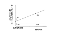
図6はこのような現象を説明するためのグラフである。図6の縦軸は微分値d(abyfs)/dtに基いて取得されたインバランス判定用パラメータである。図6の横軸は空燃比センサの使用時間である。図6の破線は空燃比気筒間インバランス状態が発生している場合のインバランス判定用パラメータを示し、図6の実線は空燃比気筒間インバランス状態が発生していない場合のインバランス判定用パラメータを示す。 FIG. 6 is a graph for explaining such a phenomenon. The vertical axis in FIG. 6 is an imbalance determination parameter acquired based on the differential value d (abyfs) / dt. The horizontal axis in FIG. 6 is the usage time of the air-fuel ratio sensor. The broken line in FIG. 6 shows the imbalance determination parameter when the air-fuel ratio imbalance state between cylinders is occurring, and the solid line in FIG. 6 is for imbalance determination when the air-fuel ratio imbalance state between cylinders does not occur. Indicates a parameter.
図6の点P1及び点P2に示されるように、空燃比センサが使用初期段階にあって、その応答性が良好でないとき、空燃比気筒間インバランス状態が発生している場合のインバランス判定用パラメータと、空燃比気筒間インバランス状態が発生していない場合のインバランス判定用パラメータと、の差は小さくなる。従って、空燃比気筒間インバランス状態が発生したか否かを誤判定する虞がある。 As indicated by points P1 and P2 in FIG. 6, when the air-fuel ratio sensor is in the initial stage of use and its responsiveness is not good, an imbalance determination is made when an air-fuel ratio imbalance among cylinders is occurring. The difference between the use parameter and the imbalance determination parameter when the air-fuel ratio imbalance among cylinders does not occur is small. Therefore, there is a risk of erroneously determining whether or not an air-fuel ratio imbalance state between cylinders has occurred.
これに対し、点P3及び点P4に示されるように、空燃比センサがある程度の時間使用されると、排ガス側電極層における反応速度が大きくなる等の理由により、空燃比気筒間インバランス状態が発生している場合のインバランス判定用パラメータと、空燃比気筒間インバランス状態が発生していない場合のインバランス判定用パラメータと、の差が大きくなる。従って、空燃比気筒間インバランス状態が発生したか否かを精度良く判定することができる。 On the other hand, as indicated by the points P3 and P4, when the air-fuel ratio sensor is used for a certain period of time, the air-fuel ratio imbalance state between the cylinders is increased because the reaction rate in the exhaust gas side electrode layer increases. The difference between the imbalance determination parameter when it occurs and the imbalance determination parameter when the air-fuel ratio imbalance among cylinders does not occur increases. Therefore, it can be accurately determined whether or not an air-fuel ratio imbalance among cylinders has occurred.
一方、空燃比センサの出力応答性は、排ガス側電極層と大気側電極層との間に「空燃比を検出する場合に印加される電圧(空燃比検出用電圧)よりも大きい電圧(センサ応答性増大用電圧)」を印加することにより、向上することが知られている。即ち、センサ応答性増大用電圧を印加することは、空燃比センサの出力応答性に関して、空燃比センサの使用時間を長くしたことと同等の作用をもたらす。センサ応答性増大用電圧を印加することにより空燃比センサの出力応答性が向上するのは、例えば、排ガス側電極層内の酸化物中の酸素が酸化物から引き離される(即ち、酸化物が還元される)ことによると考えられる。しかしながら、空燃比センサの出力応答性が良好であって精度の良いインバランス判定用パラメータが取得され得る場合においても、このようなセンサ応答性増大用電圧を印加することは、電力を無駄に消費し、或いは、空燃比センサを逆に劣化させる虞もある。 On the other hand, the output responsiveness of the air-fuel ratio sensor is a voltage (sensor response larger than the voltage applied when detecting the air-fuel ratio (air-fuel ratio detection voltage) between the exhaust gas side electrode layer and the atmosphere side electrode layer. It is known that the voltage can be improved by applying a voltage for increasing the property) ”. That is, applying the voltage for increasing the sensor responsiveness brings about an effect equivalent to increasing the use time of the air-fuel ratio sensor with respect to the output responsiveness of the air-fuel ratio sensor. The output response of the air-fuel ratio sensor is improved by applying the sensor response increasing voltage. For example, oxygen in the oxide in the exhaust gas side electrode layer is separated from the oxide (that is, the oxide is reduced). It is thought that However, even when the output response of the air-fuel ratio sensor is good and accurate imbalance determination parameters can be acquired, applying such a sensor response increase voltage wastes power. Alternatively, the air-fuel ratio sensor may be deteriorated conversely.
従って、本発明の目的の一つは、電力の無駄な消費を回避しながら、空燃比センサの出力応答性を改善し、以って、空燃比気筒間インバランス判定を精度良く行うことが可能な内燃機関の制御装置(以下、単に「本発明装置」とも称呼する。)を提供することにある。 Accordingly, one of the objects of the present invention is to improve the output responsiveness of the air-fuel ratio sensor while avoiding wasteful consumption of electric power, and thereby to accurately determine the air-fuel ratio imbalance among cylinders. An internal combustion engine control device (hereinafter also simply referred to as “the device of the present invention”) is provided.
本発明装置は、多気筒内燃機関に適用され、空燃比センサと、空燃比検出用電圧印加手段と、複数の燃料噴射弁と、空燃比フィードバック制御手段と、インバランス判定手段と、応答性判定手段と、応答性増大処理実行手段と、を備える。 The present invention device is applied to a multi-cylinder internal combustion engine, and includes an air-fuel ratio sensor, an air-fuel ratio detection voltage applying means, a plurality of fuel injection valves, an air-fuel ratio feedback control means, an imbalance determination means, and a responsiveness determination. And responsiveness increasing process executing means.
空燃比センサは、「排気集合部」又は「排気通路であって排気集合部よりも下流側の部位」に配設される。空燃比センサは、少なくとも、固体電解質層と、固体電解質層の一面に形成された排ガス側電極層と、排ガス側電極層を覆うとともに排ガスが到達する拡散抵抗層と、固体電解質層の他面に形成されるとともに大気室内に露呈された大気側電極層と、を有する空燃比検出部を含む。 The air-fuel ratio sensor is disposed in an “exhaust collecting portion” or “a portion of the exhaust passage downstream of the exhaust collecting portion”. The air-fuel ratio sensor includes at least a solid electrolyte layer, an exhaust gas side electrode layer formed on one surface of the solid electrolyte layer, a diffusion resistance layer that covers the exhaust gas side electrode layer and reaches the exhaust gas, and on the other surface of the solid electrolyte layer. And an air-fuel ratio detection unit that is formed and exposed to the atmosphere-side electrode layer.
空燃比センサは、空燃比検出用電圧印加手段により空燃比検出用電圧が印加されたとき、固体電解質層を流れる限界電流に基いて同空燃比センサが配設された部位を通過する排ガスの空燃比に応じた出力値を出力する。 When the air-fuel ratio detection voltage is applied by the air-fuel ratio detection voltage applying means, the air-fuel ratio sensor is based on the limit current flowing through the solid electrolyte layer and the exhaust gas passing through the portion where the air-fuel ratio sensor is disposed is emptied. An output value corresponding to the fuel ratio is output.
燃料噴射弁のそれぞれは、複数の気筒のそれぞれに対応するように設けられている。 Each of the fuel injection valves is provided so as to correspond to each of the plurality of cylinders.
空燃比フィードバック制御手段は、「排ガス側電極層と大気側電極層との間に前記空燃比検出用電圧が印加されている場合の空燃比センサの出力値」により表される空燃比と、理論空燃比に(実質的に)設定された目標空燃比と、が一致するように、前記燃料噴射弁から噴射される燃料噴射量をフィードバック制御する。 The air-fuel ratio feedback control means includes an air-fuel ratio expressed by “the output value of the air-fuel ratio sensor when the air-fuel ratio detection voltage is applied between the exhaust gas side electrode layer and the atmosphere side electrode layer”, and the theoretical The fuel injection amount injected from the fuel injection valve is feedback-controlled so that the target air-fuel ratio set (substantially) to the air-fuel ratio matches.
インバランス判定手段は、前記フィードバック制御が実行されている期間において、「空燃比センサが配設された部位を通過する排ガスの空燃比の変動」が大きくなるほど大きくなるインバランス判定用パラメータを、空燃比センサの出力値に基づいて取得する。更に、インバランス判定手段は、インバランス判定用パラメータが所定のインバランス判定用閾値よりも大きいとき空燃比気筒間インバランス状態が発生したと判定する。 The imbalance determination means sets an imbalance determination parameter that becomes larger as the “fluctuation in the air-fuel ratio of the exhaust gas passing through the portion where the air-fuel ratio sensor is provided” increases during the period in which the feedback control is performed. Obtained based on the output value of the fuel ratio sensor. Further, the imbalance determination means determines that an air-fuel ratio imbalance among cylinders has occurred when the imbalance determination parameter is larger than a predetermined imbalance determination threshold.
このように、インバランス判定用パラメータは、空燃比のフィードバック制御中に空燃比センサの出力値に基いて取得される。即ち、インバランス判定用パラメータは、空燃比センサが配設された部位を通過する排ガスの空燃比が理論空燃比領域において変動する状況において取得される。従って、空燃比センサの出力応答性が低い場合、インバランス判定用パラメータは「空燃比気筒間インバランス状態の程度」を十分な精度にて表さなくなる。 Thus, the imbalance determination parameter is acquired based on the output value of the air-fuel ratio sensor during the air-fuel ratio feedback control. That is, the imbalance determination parameter is acquired in a situation where the air-fuel ratio of the exhaust gas that passes through the portion where the air-fuel ratio sensor is disposed varies in the stoichiometric air-fuel ratio region. Therefore, when the output responsiveness of the air-fuel ratio sensor is low, the imbalance determination parameter does not represent “the degree of the air-fuel ratio imbalance state between cylinders” with sufficient accuracy.
そこで、応答性判定手段は、空燃比センサが配設された部位を通過する排ガスの空燃比が理論空燃比を横切るように変化する場合における「空燃比センサ出力値の変化速度に応じた値(即ち、応答性指標値)」を、空燃比センサの出力値に基いて取得する。更に、応答性判定手段は、その応答性指標値と所定の閾値とを比較することにより、空燃比センサの出力応答性が許容応答性未満であるか否かを判定する。 Therefore, the responsiveness determining means determines that the value according to the change rate of the air-fuel ratio sensor output value when the air-fuel ratio of the exhaust gas that passes through the part where the air-fuel ratio sensor is arranged changes across the theoretical air-fuel ratio ( That is, the responsiveness index value) ”is acquired based on the output value of the air-fuel ratio sensor. Further, the responsiveness determining means determines whether or not the output responsiveness of the air-fuel ratio sensor is less than the allowable responsiveness by comparing the responsiveness index value with a predetermined threshold value.
応答性増大処理実行手段は、応答性判定手段により「空燃比センサの出力応答性が許容応答性未満である」と判定された場合、空燃比センサの出力応答性を向上させるための応答性増大処理を実行する。より具体的に述べると、応答性増大処理実行手段は、排ガス側電極層の電位よりも大気側電極層の電位が高くなるように、排ガス側電極層と大気側電極層との間に「空燃比検出用電圧よりも大きいセンサ応答性増大用電圧」を印加する。 The responsiveness increasing process executing means increases the responsiveness to improve the output responsiveness of the air-fuel ratio sensor when the responsiveness determining means determines that the output responsiveness of the air-fuel ratio sensor is less than the allowable responsiveness. Execute the process. More specifically, the responsiveness increasing process execution means “empties between the exhaust gas side electrode layer and the atmosphere side electrode layer so that the potential of the atmosphere side electrode layer is higher than the potential of the exhaust gas side electrode layer. A sensor response increasing voltage that is larger than the fuel ratio detection voltage is applied.
この応答性増大処理が実行される結果、排ガス側電極層内の酸化物が還元され、或いは、排ガス側電極層と固体電解質層と排ガスとの界面の状態が「排ガス側電極層における反応が活発化する状態」へと変化するので、空燃比センサの出力応答性が増大する。その結果、インバランス判定用パラメータが「空燃比気筒間インバランス状態の程度」を精度良く表す値になる。従って、インバランス判定を精度良く行うことができる。 As a result of executing this responsiveness increasing process, the oxide in the exhaust gas side electrode layer is reduced, or the state of the interface between the exhaust gas side electrode layer, the solid electrolyte layer and the exhaust gas is “the reaction in the exhaust gas side electrode layer is active. Therefore, the output responsiveness of the air-fuel ratio sensor is increased. As a result, the imbalance determination parameter becomes a value that accurately represents “the degree of the air-fuel ratio imbalance among cylinders”. Therefore, imbalance determination can be performed with high accuracy.
しかも、応答性増大処理は、空燃比センサの出力応答性が許容応答性未満である場合に実行され、空燃比センサの出力応答性が許容応答性以上である場合には実行されない。この結果、無駄に電力を消費すること及び/又は空燃比センサが劣化することを回避することができる。 In addition, the responsiveness increasing process is executed when the output responsiveness of the air-fuel ratio sensor is less than the allowable responsiveness, and is not executed when the output responsiveness of the air-fuel ratio sensor is greater than or equal to the allowable responsiveness. As a result, it is possible to avoid wasteful power consumption and / or deterioration of the air-fuel ratio sensor.
応答性指標値は、「前記空燃比センサが配設された部位を通過する排ガスの空燃比」が「理論空燃比よりも大きい第1リーン空燃比」から「理論空燃比よりも小さい第1リッチ空燃比」へと変化した場合において、「前記空燃比センサの出力値により表される空燃比」が「理論空燃比よりも大きく且つ前記第1リーン空燃比よりも小さい第2リーン空燃比」から「理論空燃比よりも小さく且つ前記第1リッチ空燃比よりも大きい第2リッチ空燃比」へと変化するまでの時間(第1の応答時間)に基く値であってもよい。 The responsiveness index value is the first rich value in which “the air-fuel ratio of the exhaust gas passing through the portion where the air-fuel ratio sensor is disposed” is “the first lean air-fuel ratio larger than the theoretical air-fuel ratio” to “the first rich air-fuel ratio smaller than the theoretical air-fuel ratio”. When the air-fuel ratio is changed to “air-fuel ratio”, the “air-fuel ratio represented by the output value of the air-fuel ratio sensor” is greater than “the second lean air-fuel ratio that is larger than the theoretical air-fuel ratio and smaller than the first lean air-fuel ratio”. The value may be a value based on the time (first response time) until it changes to “a second rich air-fuel ratio smaller than the theoretical air-fuel ratio and larger than the first rich air-fuel ratio”.
応答性指標値は、「前記空燃比センサが配設された部位を通過する排ガスの空燃比」が「理論空燃比よりも小さい第3リッチ空燃比」から「理論空燃比よりも大きい第3リーン空燃比」へと変化した場合において、「前記空燃比センサの出力値により表される空燃比」が「理論空燃比よりも小さく且つ前記第3リッチ空燃比よりも大きい第4リッチ空燃比」から「理論空燃比よりも大きく且つ前記第3リーン空燃比よりも小さい第4リーン空燃比」へと変化するまでの時間(第2の応答時間)に基く値であってもよい。 The responsiveness index value is a third lean air-fuel ratio in which “the air-fuel ratio of the exhaust gas passing through the part where the air-fuel ratio sensor is disposed” is “a third rich air-fuel ratio smaller than the stoichiometric air-fuel ratio” to “a third lean air fuel ratio larger than the stoichiometric air-fuel ratio”. When the air-fuel ratio is changed to “air-fuel ratio”, the “air-fuel ratio represented by the output value of the air-fuel ratio sensor” is smaller than “the fourth rich air-fuel ratio that is smaller than the theoretical air-fuel ratio and larger than the third rich air-fuel ratio”. The value may be a value based on a time (second response time) until it changes to “a fourth lean air-fuel ratio that is larger than the theoretical air-fuel ratio and smaller than the third lean air-fuel ratio”.
更に、応答性指標値は、第1の応答時間及び第2の応答時間に基づいて得られる値(例えば、第1の応答時間及び第2の応答時間の平均値)であってもよい。 Furthermore, the responsiveness index value may be a value obtained based on the first response time and the second response time (for example, an average value of the first response time and the second response time).
加えて、応答性増大処理は、前記機関の運転停止後に実行されることが望ましい。その際、「空燃比センサが配設された部位に存在する排ガスの空燃比」が理論空燃比よりも小さい空燃比となるように、機関の運転停止前において燃料噴射弁から噴射される燃料噴射量が制御されてもよい。これにより、センサ応答性増大用電圧が印加されたとき、排ガス側電極層の酸化物に含まれる酸素は、多量の未燃物と反応するので、一層効率的に除去され得る。 In addition, it is desirable that the responsiveness increasing process is executed after the engine is stopped. At that time, the fuel injection injected from the fuel injection valve before the operation of the engine is stopped so that the “air-fuel ratio of the exhaust gas existing in the portion where the air-fuel ratio sensor is disposed” becomes an air-fuel ratio smaller than the stoichiometric air-fuel ratio. The amount may be controlled. Thereby, when the sensor response increasing voltage is applied, oxygen contained in the oxide of the exhaust gas side electrode layer reacts with a large amount of unburned matter, and thus can be more efficiently removed.
更に、応答性増大処理は、機関の停止後において、固体電解質層の温度が、機関の運転中における固体電解質層の温度よりも高い温度になるように、空燃比センサのヒータへ電力を供給することを含んでいてもよい。これにより、排ガス側電極層の酸化物が一層効率的に除去され得る。 Further, in the responsiveness increasing process, after the engine is stopped, power is supplied to the heater of the air-fuel ratio sensor so that the temperature of the solid electrolyte layer becomes higher than the temperature of the solid electrolyte layer during operation of the engine. It may include. Thereby, the oxide of the exhaust gas side electrode layer can be removed more efficiently.
本発明装置の他の目的、他の特徴及び付随する利点は、以下の図面を参照しつつ記述される本発明装置の実施形態についての説明から容易に理解されるであろう。 Other objects, other features and attendant advantages of the inventive apparatus will be readily understood from the description of the embodiments of the inventive apparatus described with reference to the following drawings.
以下、本発明の実施形態に係る内燃機関の制御装置(以下、単に「制御装置」とも称呼する。)について図面を参照しながら説明する。この制御装置は、内燃機関に供給される混合気の空燃比(機関の空燃比)を制御する「空燃比制御装置」である。更に、この制御装置は、空燃比気筒間インバランス状態が発生したか否かを判定する「空燃比気筒間インバランス判定装置」でもある。 Hereinafter, a control device for an internal combustion engine according to an embodiment of the present invention (hereinafter also simply referred to as “control device”) will be described with reference to the drawings. This control device is an “air-fuel ratio control device” that controls the air-fuel ratio of the air-fuel mixture supplied to the internal combustion engine (the air-fuel ratio of the engine). Furthermore, this control device is also an “air-fuel ratio imbalance among cylinders determination device” that determines whether or not an air-fuel ratio imbalance among cylinders has occurred.
(構成)
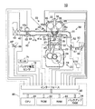
図7は、この制御装置を、4サイクル・火花点火式・多気筒(直列4気筒)・内燃機関10に適用したシステムの概略構成を示している。なお、図7は、特定気筒の断面のみを示しているが、他の気筒も同様な構成を備えている。
(Constitution)
FIG. 7 shows a schematic configuration of a system in which this control device is applied to a 4-cycle, spark ignition type, multi-cylinder (in-line 4-cylinder)
この内燃機関10は、シリンダブロック、シリンダブロックロワーケース及びオイルパン等を含むシリンダブロック部20と、シリンダブロック部20の上に固定されるシリンダヘッド部30と、シリンダブロック部20にガソリン混合気を供給するための吸気系統40と、シリンダブロック部20からの排ガスを外部に放出するための排気系統50と、を含んでいる。
The
シリンダブロック部20は、シリンダ21、ピストン22、コンロッド23及びクランク軸24を含んでいる。ピストン22はシリンダ21内を往復動し、ピストン22の往復動がコンロッド23を介してクランク軸24に伝達され、これにより同クランク軸24が回転するようになっている。シリンダ21の壁面及びピストン22の上面は、シリンダヘッド部30の下面とともに燃焼室25を形成している。
The
シリンダヘッド部30は、燃焼室25に連通した吸気ポート31、吸気ポート31を開閉する吸気弁32、吸気弁32を駆動するインテークカムシャフトを含むとともに同インテークカムシャフトの位相角を連続的に変更する可変吸気タイミング制御装置33、可変吸気タイミング制御装置33のアクチュエータ33a、燃焼室25に連通した排気ポート34、排気ポート34を開閉する排気弁35、排気弁35を駆動するエキゾーストカムシャフトを含むとともに同エキゾーストカムシャフトの位相角を連続的に変更する可変排気タイミング制御装置36、可変排気タイミング制御装置36のアクチュエータ36a、点火プラグ37、点火プラグ37に与える高電圧を発生するイグニッションコイルを含むイグナイタ38及び燃料噴射弁(燃料噴射手段、燃料供給手段)39を備えている。
The
燃料噴射弁39は、図1にも示したように、一つの燃焼室25に対して一つずつ配設されている。燃料噴射弁39は吸気ポート31に設けられている。燃料噴射弁39は、噴射指示信号に応答し、正常である場合に「その噴射指示信号に含まれる指示燃料噴射量の燃料」を対応する吸気ポート31内に噴射するようになっている。このように、複数の気筒のそれぞれは、他の気筒とは独立して燃料供給を行う燃料噴射弁39を備えている。
As shown in FIG. 1, one
吸気系統40は、インテークマニホールド41、吸気管42、エアフィルタ43、及び、スロットル弁44を備えている。
The
インテークマニホールド41は、図1に示したように、複数の枝部41aとサージタンク41bとからなる。複数の枝部41aのそれぞれの一端は、図7に示したように、複数の吸気ポート31のそれぞれに接続されている。複数の枝部41aの他端はサージタンク41bに接続されている。吸気管42の一端はサージタンク41bに接続されている。エアフィルタ43は吸気管42の他端に配設されている。スロットル弁44は、吸気管42内にあって吸気通路の開口断面積を可変とするようになっている。スロットル弁44は、DCモータからなるスロットル弁アクチュエータ44a(スロットル弁駆動手段の一部)により吸気管42内で回転駆動されるようになっている。
As shown in FIG. 1, the
排気系統50は、エキゾーストマニホールド51、エキゾーストパイプ52、エキゾーストパイプ52に配設された上流側触媒53、及び、上流側触媒53よりも下流のエキゾーストパイプ52に配設された図示しない下流側触媒を備えている。
The
エキゾーストマニホールド51は、図1に示したように、それぞれの一端が排気ポートに接続された複数の枝部51aと、その複数の枝部51aのそれぞれの他端であって総ての枝部51aが集合している集合部51bとを備えている。この集合部51bは、複数(2以上であり、本例では4つ)の気筒から排出された排ガスが集合するから、排気集合部HKとも称呼される。エキゾーストパイプ52は集合部51bに接続されている。図7に示したように、排気ポート34、エキゾーストマニホールド51及びエキゾーストパイプ52は、排気通路を構成している。
As shown in FIG. 1, the
上流側触媒53及び下流側触媒のそれぞれは、所謂、白金、ロジウム及びパラジウム等の貴金属(触媒物質)からなる活性成分を担持する三元触媒装置(排気浄化触媒)である。各触媒は、各触媒に流入するガスの空燃比が理論空燃比であるとき、HC,CO,H2などの未燃成分を酸化するとともに窒素酸化物(NOx)を還元する機能を有する。この機能は触媒機能とも称呼される。更に、各触媒は、酸素を吸蔵(貯蔵)する酸素吸蔵機能を有し、この酸素吸蔵機能により空燃比が理論空燃比から偏移したとしても未燃成分及び窒素酸化物を浄化することができる。この酸素吸蔵機能は、触媒に担持されているセリア(CeO2)等の酸素吸蔵材によってもたらされる。
Each of the
このシステムは、熱線式エアフローメータ61、スロットルポジションセンサ62、水温センサ63、クランクポジションセンサ64、インテークカムポジションセンサ65、エキゾーストカムポジションセンサ66、上流側空燃比センサ67、下流側空燃比センサ68、アクセル開度センサ69、イグニッション・キー・スイッチ71及びバッテリ電圧センサ72を備えている。
This system includes a hot-wire
エアフローメータ61は、吸気管42内を流れる吸入空気の質量流量Gaに応じた信号を出力するようになっている。即ち、吸入空気量Gaは、単位時間あたりに機関10に吸入される空気量を表す。
スロットルポジションセンサ62は、スロットル弁44の開度(スロットル弁開度)を検出し、スロットル弁開度TAを表す信号を出力するようになっている。
水温センサ63は、内燃機関10の冷却水の温度を検出し、冷却水温THWを表す信号を出力するようになっている。
The
The
The
クランクポジションセンサ64は、クランク軸24が10°回転する毎に幅狭のパルスを有するとともに同クランク軸24が360°回転する毎に幅広のパルスを有する信号を出力するようになっている。この信号は、後述する電気制御装置80によって機関回転速度NEに変換される。
The crank
インテークカムポジションセンサ65は、インテークカムシャフトが所定角度から90度、次いで90度、更に180度回転する毎に一つのパルスを出力するようになっている。後述する電気制御装置80は、クランクポジションセンサ64及びインテークカムポジションセンサ65からの信号に基づいて、基準気筒(例えば第1気筒)の圧縮上死点を基準とした絶対クランク角CAを取得するようになっている。この絶対クランク角CAは、基準気筒の圧縮上死点において「0°クランク角」に設定され、クランク角の回転角度に応じて720°クランク角まで増大し、その時点にて再び0°クランク角に設定される。
The intake
エキゾーストカムポジションセンサ66は、エキゾーストカムシャフトが所定角度から90度、次いで90度、更に180度回転する毎に一つのパルスを出力するようになっている。
The exhaust
上流側空燃比センサ67(本発明における空燃比センサ)は、図1にも示したように、エキゾーストマニホールド51の集合部51b(排気集合部HK)と上流側触媒53との間の位置において「エキゾーストマニホールド51及びエキゾーストパイプ52の何れか(即ち、排気通路)」に配設されている。上流側空燃比センサ67は、例えば、特開平11−72473号公報、特開2000−65782号公報及び特開2004−69547号公報等に開示された「拡散抵抗層を備える限界電流式広域空燃比センサ」である。
As shown in FIG. 1, the upstream air-fuel ratio sensor 67 (the air-fuel ratio sensor in the present invention) is “at a position between the collecting
上流側空燃比センサ67は、図8及び図9に示したように、空燃比検出部67aと、外側保護カバー67bと、内側保護カバー67cと、を有している。
As shown in FIGS. 8 and 9, the upstream air-
外側保護カバー67bは金属からなる中空円筒体である。外側保護カバー67bは内側保護カバー67cを覆うように、内側保護カバー67cを内部に収容している。外側保護カバー67bは、流入孔67b1をその側面に複数備えている。流入孔67b1は、排気通路を流れる排ガス(外側保護カバー67bの外部の排ガス)EXを外側保護カバー67bの内部に流入させるための貫通孔である。更に、外側保護カバー67bは、外側保護カバー67bの内部の排ガスを外部(排気通路)に流出させるための流出孔67b2をその底面に有している。
The outer
内側保護カバー67cは、金属からなり、外側保護カバー67bの直径よりも小さい直径を有する中空円筒体である。内側保護カバー67cは、空燃比検出部67aを覆うように空燃比検出部67aを内部に収容している。内側保護カバー67cは流入孔67c1をその側面に複数備えている。この流入孔67c1は、外側保護カバー67bの流入孔67b1を通して「外側保護カバー67bと内側保護カバー67cとの間の空間」に流入した排ガスを、内側保護カバー67cの内部に流入させるための貫通孔である。更に、内側保護カバー67cは、内側保護カバー67cの内部の排ガスを外部に流出させるための流出孔67c2をその底面に有している。
The inner
図2の(A)〜(C)に示したように、空燃比検出部67aは、固体電解質層671と、排ガス側電極層672と、大気側電極層673と、拡散抵抗層674と、第一壁部675と、触媒部676と、第二壁部677と、ヒータ678と、を含んでいる。
As shown in FIGS. 2A to 2C, the air-
固体電解質層671は酸素イオン導電性酸化物焼結体である。本例において、固体電解質層671は、ZrO2(ジルコニア)にCaOを安定剤として固溶させた「安定化ジルコニア素子」である。固体電解質層671は、その温度が活性温度以上であるとき、周知の「酸素電池特性」及び「酸素ポンプ特性」を発揮する。
The
排ガス側電極層672は、白金(Pt)及びロジウム(Rh)等の触媒活性の高い貴金属からなる。排ガス側電極層672は、固体電解質層671の一つの面上に形成されている。排ガス側電極層672は、化学メッキ等により浸透性を十分に有するように(即ち、多孔質状に)形成されている。
The exhaust gas
大気側電極層673は、白金(Pt)等の触媒活性の高い貴金属からなる。大気側電極層673は、固体電解質層671の他の面上であって、固体電解質層671を挟んで排ガス側電極層672に対向するように形成されている。大気側電極層673は、化学メッキ等により浸透性を十分に有するように(即ち、多孔質状に)形成されている。
The atmosphere-
拡散抵抗層(拡散律速層)674は、多孔質セラミック(耐熱性無機物質)からなる。拡散抵抗層674は、排ガス側電極層672の外側表面を覆うように、例えば、プラズマ溶射法等により形成されている。
The diffusion resistance layer (diffusion limiting layer) 674 is made of porous ceramic (heat-resistant inorganic substance). The
第一壁部675は、緻密であってガスを透過させないアルミナセラミックスからなる。第一壁部675は拡散抵抗層674の角部(一部)を除いて拡散抵抗層674を覆うように形成されている。即ち、第一壁部675は拡散抵抗層674の一部を外部に露呈させる貫通部を備えている。
The
触媒部676は、第一壁部675の貫通部を閉じるように貫通部に形成されている。触媒部676は、上流側触媒53と同様、酸化還元反応を促進する触媒物質及び酸素吸蔵機能を発揮する酸素吸蔵材を担持している。触媒部676は多孔質体である。従って、図2の(B)及び図2の(C)に白抜きの矢印により示したように、排ガス(前述した内側保護カバー67cの内部に流入した排ガス)は、触媒部676を通過して拡散抵抗層674に到達し、その排ガスは更に拡散抵抗層674を通過して排ガス側電極層672に到達する。
The
第二壁部677は、緻密であってガスを透過させないアルミナセラミックスからなる。第二壁部677は大気側電極層673を収容する空間である「大気室67A」を形成するように構成されている。大気室67Aには大気が導入されている。
The
上流側空燃比センサ67には電源(印加電圧調整手段)679が接続されている。電源679は、上流側空燃比センサ67が空燃比を検出する必要がある場合、後述する電気制御装置80からの指示に応答して、排ガス側電極層672の電位よりも大気側電極層673の電位が電圧Vpだけ高くなるように、排ガス側電極層672と大気側電極層673との間に空燃比検出用電圧Vp(例えば、0.4V)を印加するようになっている。更に、電源679は、上流側空燃比センサ67の応答性を増大する必要がある場合、後述する電気制御装置80からの指示に応答して、排ガス側電極層672の電位よりも大気側電極層673の電位が電圧Vupだけ高くなるように、排ガス側電極層672と大気側電極層673との間にセンサ応答性増大用電圧Vupを印加するようになっている。センサ応答性増大用電圧Vupは、例えば、2Vであり、空燃比検出用電圧Vpよりも大きい。
A power supply (applied voltage adjusting means) 679 is connected to the upstream air-
ヒータ678は第二壁部677に埋設されている。ヒータ678は後述する電気制御装置80によって通電されたときに発熱し、固体電解質層671、排ガス側電極層672及び大気側電極層673を加熱し、それらの温度を調整するようになっている。以下、ヒータ678により加熱される「固体電解質層671、排ガス側電極層672及び大気側電極層673」を「センサ素子部、又は、空燃比センサ素子」とも称呼する。従って、ヒータ678は、センサ素子部の温度である「空燃比センサ素子温度」を制御するようになっている。
The
ヒータ678の通電量(ヒータ678を流れる電流)が大きいほど、ヒータ678の発熱量は大きくなる。ヒータ678の通電量は、電気制御装置80が出力するデューティ信号(以下、「ヒータデューティDuty」とも称呼する。)が大きいほど大きくなるように調整される。ヒータデューティDutyが100%であるときヒータ678の発熱量は最大となる。ヒータデューティDutyが0%であるときヒータ678への通電は遮断され、その結果、ヒータ678は発熱しない。
The greater the energization amount of the heater 678 (the current flowing through the heater 678), the greater the amount of heat generated by the
空燃比センサ素子温度は固体電解質層671のアドミタンスYとともに変化する。換言すると、アドミタンスYに基いて空燃比センサ素子温度を推定することができる。一般に、アドミタンスYが大きいほど空燃比センサ素子温度は高くなる。電気制御装置80は、排ガス側電極層672と大気側電極層673との間に、「矩形波又は正弦波等の電圧」を「電源679による空燃比検出用電圧Vp又はセンサ応答性増大用電圧Vup」に周期的に重畳させ、その際に固体電解質層671に流れる電流に基いて、実際の空燃比センサ67(固体電解質層671)のアドミタンスYactを取得するようになっている。
The air-fuel ratio sensor element temperature changes with the admittance Y of the
上流側空燃比センサ67は、図2の(B)に示したように、空燃比検出用電圧Vpが印加され且つ排ガスの空燃比が理論空燃比よりもリーン側の空燃比であるとき、拡散抵抗層674を通って排ガス側電極層672に到達した酸素をイオン化して大気側電極層673へと通過させる。この結果、電源679の正極から負極へと電流Iが流れる。この電流Iの大きさは、図3に示したように、排ガス側電極層672に到達した酸素の濃度(酸素分圧、排ガスの空燃比)に比例した一定値となる。上流側空燃比センサ67は、この電流(即ち、限界電流Ip)を電圧に変換した値を出力値Vabyfsとして出力する。
As shown in FIG. 2B, the upstream air-
これに対し、図2の(C)に示したように、空燃比検出用電圧Vpが印加され且つ排ガスの空燃比が理論空燃比よりもリッチ側の空燃比であるとき、上流側空燃比センサ67は、大気室67Aに存在する酸素をイオン化して排ガス側電極層672へと導き、拡散抵抗層674を通って排ガス側電極層672に到達する未燃物(HC,CO及びH2等)を酸化する。この結果、電源679の負極から正極へと電流Iが流れる。この電流Iの大きさも、図3に示したように、排ガス側電極層672に到達した未燃物の濃度(即ち、排ガスの空燃比)に比例した一定値となる。上流側空燃比センサ67は、この電流(即ち、限界電流Ip)を電圧に変換した値を出力値Vabyfsとして出力する。
On the other hand, as shown in FIG. 2C, when the air-fuel ratio detection voltage Vp is applied and the air-fuel ratio of the exhaust gas is richer than the stoichiometric air-fuel ratio, the upstream air-fuel ratio sensor. 67 is an unburned substance (HC, CO, H 2, etc.) that ionizes oxygen present in the
即ち、空燃比検出部67aは、図4に示したように、上流側空燃比センサ67の配設位置を流れ、且つ、外側保護カバー67bの流入孔67b1及び内側保護カバー67cの流入孔67c1を通って空燃比検出部67aに到達しているガスの空燃比(上流側空燃比abyfs、検出空燃比abyfs)に応じた出力値Vabyfsを「空燃比センサ出力」として出力する。出力値Vabyfsは、空燃比検出部67aに到達しているガスの空燃比が大きくなるほど(リーンとなるほど)増大する。即ち、出力値Vabyfsは、空燃比検出部67aに到達している排ガスの空燃比に実質的に比例する。
That is, as shown in FIG. 4, the air-fuel
電気制御装置80は、図4に示した空燃比変換テーブル(マップ)Mapabyfsを記憶していて、空燃比センサ67の出力値Vabyfsを空燃比変換テーブルMapabyfsに適用することにより、実際の上流側空燃比abyfsを検出する(即ち、検出空燃比abyfsを取得する)。
The
ところで、上流側空燃比センサ67は、エキゾーストマニホールド51の排気集合部HKと上流側触媒53との間の位置においてエキゾーストマニホールド51及びエキゾーストパイプ52の何れかに外側保護カバー67bが露呈するように配設される。
Meanwhile, the upstream air-
より具体的には、空燃比センサ67は、図8及び図9に示したように、保護カバー(67b、67c)の底面が排ガスEXの流れと平行であり、保護カバー(67b、67c)の中心軸線CCが排ガスEXの流れと直交するように排気通路内に配設される。これにより、外側保護カバー67bの流入孔67b1に到達した排気通路内の排ガスEXは、外側保護カバー67bの流出孔67b2近傍を流れる排気通路内の排ガスEXの流れにより、外側保護カバー67b及び内側保護カバー67cの内部へと吸い込まれる。
More specifically, as shown in FIGS. 8 and 9, the air-
従って、排気通路を流れる排ガスEXは、図8及び図9において矢印Ar1により示したように外側の保護カバー67bの流入孔67b1を通って外側の保護カバー67bと内側の保護カバー67cとの間に流入する。次いで、その排ガスは、矢印Ar2に示したように「内側の保護カバー67cの流入孔67c1」を通って「内側の保護カバー67cの内部」に流入した後に、空燃比検出部67aに到達する。その後、その排ガスは、矢印Ar3に示したように「内側の保護カバー67cの流出孔67c2及び外側の保護カバー67bの流出孔67b2」を通って排気通路に流出する。
Accordingly, the exhaust gas EX flowing through the exhaust passage passes through the inflow hole 67b1 of the outer
このため、「外側保護カバー67b及び内側保護カバー67c」の内部における排ガスの流速は、外側保護カバー67bの流出孔67b2近傍を流れる排ガスEXの流速(従って、単位時間あたりの吸入空気量Ga)に応じて変化する。換言すると、「ある空燃比の排ガス(第1排ガス)が流入孔67b1に到達した時点」から「その第1排ガスが空燃比検出部67aに到達する時点」までの時間は、吸入空気量Gaに依存するが機関回転速度NEには依存しない。従って、空燃比センサ67の「排気通路を流れる排ガスの空燃比」に対する出力応答性は、空燃比センサ67の外側保護カバー67bの近傍を流れる排ガスの流量(流速)が大きいほど良好になる。このことは、上流側空燃比センサ67が内側保護カバー67cのみを有する場合にも成立する。
For this reason, the flow rate of the exhaust gas inside the “outer
更に、上流側空燃比センサ67の排ガス側電極層672と大気側電極層673との間にセンサ応答性増大用電圧Vupが印加された場合、排ガス側電極層672に含まれている金属酸化物等が金属へと還元される。この結果、排ガス側電極層672における排ガスの反応速度が増大するので、排ガスの空燃比が理論空燃比領域において変動する場合における上流側空燃比センサ67の出力応答性が向上する。このとき、排ガスの空燃比が理論空燃比よりもリッチ(小さい)空燃比であれば(排ガス中に過剰な未燃物が含まれているとき)、排ガス側電極層672に含まれている金属酸化物はより効果的に還元される。加えて、この状態において触媒676の貴金属に付着している酸素が消費されるので、触媒676が本来の機能を発揮するようになる。その結果、上流側空燃比センサ67の出力応答性が一層向上(回復)する。
Further, when the sensor response increasing voltage Vup is applied between the exhaust gas
再び、図7を参照すると、下流側空燃比センサ68は、エキゾーストパイプ52であって上流側触媒53よりも下流側であり且つ下流側触媒よりも上流側(即ち、上流側触媒53と下流側触媒との間の排気通路)に配設されている。下流側空燃比センサ68は、周知の起電力式の酸素濃度センサ(安定化ジルコニアを用いた周知の濃淡電池型の酸素濃度センサ)である。下流側空燃比センサ68は、排気通路であって下流側空燃比センサ68が配設されている部位を通過するガスである被検出ガスの空燃比(即ち、上流側触媒53から流出し且つ下流側触媒に流入するガスの空燃比、従って、機関に供給される混合気の空燃比の時間的平均値)に応じた出力値Voxsを発生するようになっている。
Referring again to FIG. 7, the downstream air-
この出力値Voxsは、図10に示したように、被検出ガスの空燃比が理論空燃比よりもリッチのとき最大出力値max(例えば、約0.9V)となり、被検出ガスの空燃比が理論空燃比よりもリーンのとき最小出力値min(例えば、約0.1V)となり、被検出ガスの空燃比が理論空燃比であるとき最大出力値maxと最小出力値minの略中間の電圧Vst(中間電圧Vst、例えば、約0.5V)となる。更に、この出力値Voxsは、被検出ガスの空燃比が理論空燃比よりもリッチな空燃比からリーンな空燃比へと変化する際に最大出力値maxから最小出力値minへと急変し、被検出ガスの空燃比が理論空燃比よりもリーンな空燃比からリッチな空燃比へと変化する際に最小出力値minから最大出力値maxへと急変する。 As shown in FIG. 10, the output value Voxs becomes the maximum output value max (for example, about 0.9 V) when the air-fuel ratio of the detected gas is richer than the stoichiometric air-fuel ratio, and the air-fuel ratio of the detected gas is When the air-fuel ratio is leaner than the stoichiometric air-fuel ratio, the minimum output value min (for example, approximately 0.1 V) is obtained. (Intermediate voltage Vst, for example, about 0.5 V). Further, this output value Voxs suddenly changes from the maximum output value max to the minimum output value min when the air-fuel ratio of the gas to be detected changes from an air-fuel ratio richer than the stoichiometric air-fuel ratio to a lean air-fuel ratio. When the air-fuel ratio of the detection gas changes from an air-fuel ratio leaner than the stoichiometric air-fuel ratio to a rich air-fuel ratio, it suddenly changes from the minimum output value min to the maximum output value max.
図7に示したアクセル開度センサ69は、運転者によって操作されるアクセルペダルAPの操作量Accp(アクセルペダル操作量Accp)を表す信号を出力するようになっている。アクセルペダル操作量Accpは、アクセルペダルAPの開度(アクセルペダル操作量)が大きくなるとともに大きくなる。
The
イグニッション・キー・スイッチ71は、機関10が運転されているときオン位置に維持され、機関10の運転が停止されるときオフ位置に維持される。
バッテリ電圧センサ72は、機関10を搭載した車両の図示しないバッテリの電圧を検出し、そのバッテリ電圧VBを表す信号を出力するようになっている。バッテリは、上流側空燃比センサ67のヒータ678及び電源679等にも電力を供給するようになっている。
The ignition
The
電気制御装置80は、互いにバスで接続された「CPU81、CPU81が実行するプログラム、テーブル(マップ、関数)及び定数等を予め記憶したROM82、CPU81が必要に応じてデータを一時的に格納するRAM83、バックアップRAM84並びにADコンバータを含むインターフェース85等」からなる周知のマイクロコンピュータである。
The
バックアップRAM84は、イグニッション・キー・スイッチ71の位置(オフ位置、始動位置及びオン位置等の何れか)に関わらず、車両に搭載されたバッテリから電力の供給を受けるようになっている。バックアップRAM84は、バッテリから電力の供給を受けている場合、CPU81の指示に応じてデータを格納する(データが書き込まれる)とともに、そのデータを読み出し可能となるように保持(記憶)する。バックアップRAM84は、バッテリが車両から取り外される等によりバッテリからの電力供給が遮断されると、データを保持することができない。そこで、CPU81は、バックアップRAM84への電力供給が再開されたとき、バックアップRAM84に保持されるべきデータを初期化(デフォルト値に設定)するようになっている。
The
インターフェース85は、上述したセンサと接続され、CPU81にそれらのセンサからの信号を供給するようになっている。更に、インターフェース85は、CPU81の指示に応じて可変吸気タイミング制御装置33のアクチュエータ33a、可変排気タイミング制御装置36のアクチュエータ36a、各気筒のイグナイタ38、各気筒に対応して設けられた燃料噴射弁39、スロットル弁アクチュエータ44a、空燃比センサ67のヒータ678及び電源679等に駆動信号(指示信号)を送出するようになっている。
The
なお、電気制御装置80は、取得されたアクセルペダルの操作量Accpが大きくなるほどスロットル弁開度TAが大きくなるように、スロットル弁アクチュエータ44aに指示信号を送出するようになっている。即ち、電気制御装置80は、運転者により変更される機関10の加速操作量(アクセルペダル操作量Accp)に応じて「機関10の吸気通路に配設されたスロットル弁44」の開度を変更するスロットル弁駆動手段を備えている。
The
(制御の概要)
次に、この制御装置により実現される制御の概要について説明する。この制御装置は、機関10の通常運転時(メインフィードバック制御条件が成立したとき)、空燃比フィードバック制御を実行する。即ち、制御装置は、上流側空燃比センサ67の排ガス側電極層672と大気側電極層673との間に空燃比検出用電圧Vpを印加し、上流側空燃比センサ67の出力値Vabyfsに基づいて検出空燃比abyfsを取得する。加えて、制御装置は、空燃比センサ素子温度が「機関10の運転中における目標温度(例えば、700℃)」となるように、ヒータ678の通電量を制御する。更に、制御装置は、その検出空燃比abyfsが「理論空燃比に設定された目標空燃比abyfr」に一致するように、燃料噴射弁39から噴射される燃料量(燃料噴射量)をフィードバック制御する。なお、目標空燃比abyfrは、実質的に理論空燃比であればよい。即ち、目標空燃比abyfrは、上流側触媒53の所謂ウインドウの範囲内の空燃比であればよい。
(Outline of control)
Next, an outline of control realized by this control apparatus will be described. This control device executes air-fuel ratio feedback control during normal operation of the engine 10 (when the main feedback control condition is satisfied). That is, the control device applies the air-fuel ratio detection voltage Vp between the exhaust gas-
この空燃比フィードバック制御中において所定の条件(判定実行条件)が成立したとき、制御装置は検出空燃比abyfsの微分値d(abyfs)/dtを取得し、その微分値d(abyfs)/dtに基づいてインバランス判定用パラメータを取得する。そして、インバランス判定用パラメータとインバランス判定用閾値とを比較して、空燃比気筒間インバランス状態が発生しているか否かを判定する。 When a predetermined condition (determination execution condition) is satisfied during the air-fuel ratio feedback control, the control device acquires the differential value d (abyfs) / dt of the detected air-fuel ratio abyfs, and obtains the differential value d (abyfs) / dt. Based on this, an imbalance determination parameter is acquired. Then, the imbalance determination parameter and the imbalance determination threshold are compared to determine whether an air-fuel ratio imbalance state between cylinders has occurred.
一方、制御装置は、応答性指標値取得条件が成立したとき、上流側空燃比センサ67が配設された部位を通過する排ガスの空燃比が理論空燃比を横切るように変化する場合における「上流側空燃比センサ67の出力値Vabyfsの変化速度に応じた応答性指標値」を、出力値Vabyfsに基いて取得する。
On the other hand, when the responsiveness index value acquisition condition is satisfied, the control device determines that the “upstream” in the case where the air-fuel ratio of the exhaust gas passing through the portion where the upstream air-
より具体的に述べると、図11のタイムチャートに示したように、制御装置は、目標空燃比abyfrを第1リーン空燃比AFL1に所定期間(時刻t1〜時刻t2を参照。)に渡って維持する。第1リーン空燃比AFL1は理論空燃比(例えば、14.6)よりも大きい空燃比(例えば、15.0)である。その後、制御装置は、目標空燃比abyfrを第1リッチ空燃比AFR1(例えば、14.2)に所定時間に渡って維持する(時刻t2以降を参照。)。この結果、上流側空燃比センサ67が配設された部位を通過する排ガスの空燃比が、第1リーン空燃比AFL1から第1リッチ空燃比AFR1へと急変する。
More specifically, as shown in the time chart of FIG. 11, the control device maintains the target air-fuel ratio abyfr at the first lean air-fuel ratio AFL1 for a predetermined period (see time t1 to time t2). To do. The first lean air-fuel ratio AFL1 is an air-fuel ratio (for example, 15.0) larger than the stoichiometric air-fuel ratio (for example, 14.6). Thereafter, the control device maintains the target air-fuel ratio abyfr at the first rich air-fuel ratio AFR1 (for example, 14.2) for a predetermined time (see after time t2). As a result, the air-fuel ratio of the exhaust gas passing through the portion where the upstream air-
このとき、制御装置は、上流側空燃比センサ67の出力値Vabyfsにより表される検出空燃比abyfsが、第2リーン空燃比AFL2から第2リッチ空燃比AFR2へと変化するまでの時間(時間Ta及び時間Tbを参照。)を取得する。この時間は便宜上「第1の応答時間」とも称呼される。第2リーン空燃比AFL2は、理論空燃比よりも大きく且つ第1リーン空燃比AFL1よりも小さい空燃比(例えば、14.7)である。第2リッチ空燃比AFR2は、理論空燃比よりも小さく且つ第1リッチ空燃比AFR1よりも大きい空燃比(例えば、14.5)である。
At this time, the control device determines the time (time Ta) until the detected air-fuel ratio abyfs represented by the output value Vabyfs of the upstream air-
以上から理解されるように、第1の応答時間は、上流側空燃比センサ67が配設された部位を通過する排ガスの空燃比が理論空燃比を横切るように変化する場合における「上流側空燃比センサ67の出力値Vabyfsの変化速度に応じた応答性指標値」である。上流側空燃比センサ67の出力応答性が高い場合、図11に破線により示したように、第1の応答時間は比較的短い時間Tbとなる。これに対し、上流側空燃比センサ67の出力応答性が低い場合、図11に実線により示したように、第1の応答時間は比較的長い時間Taとなる。即ち、第1の応答時間は、上流側空燃比センサ67の出力応答性が高いほど短くなる。
As understood from the above, the first response time is the “upstream air-fuel ratio” in the case where the air-fuel ratio of the exhaust gas passing through the portion where the upstream air-
制御装置は、第1の応答時間(応答性指標値)と所定の閾値とを比較する。そして、制御装置は、第1の応答時間が所定の閾値よりも長い場合、上流側空燃比センサ67の出力応答性が許容応答性未満であると判定する。
The control device compares the first response time (responsiveness index value) with a predetermined threshold value. Then, when the first response time is longer than the predetermined threshold, the control device determines that the output responsiveness of the upstream air-
制御装置は、上流側空燃比センサ67の出力応答性が許容応答性未満であると判定した場合、上流側空燃比センサ67の出力応答性を向上させるための応答性増大処理を実行する。応答性増大処理は、エージング(aging)処理とも称呼される。
When it is determined that the output responsiveness of the upstream air-
より具体的に述べると、図12のタイムチャートに示したように、制御装置は、上流側空燃比センサ67の出力応答性が許容応答性未満であると判定した場合、応答性増大処理要求フラグの値を「1」に設定する(時刻t2を参照。)。制御装置は、応答性増大処理要求フラグの値が「1」に設定されている場合、機関10がアイドル運転状態にあるときの目標空燃比abyfrを「理論空燃比よりも僅かに小さい(リッチな)空燃比AFidlerich」に設定する。
More specifically, as shown in the time chart of FIG. 12, when the control device determines that the output responsiveness of the upstream air-
通常、機関10の運転が停止される直前には、機関10はアイドル運転状態になる。従って、時刻t3にて機関10の運転が停止されたとき、上流側空燃比センサ67の周囲に存在する排ガスの空燃比は「理論空燃比よりもリッチ」な空燃比となる。即ち、時刻t3にて機関10の運転が停止されたとき、上流側空燃比センサ67の周囲には過剰な未燃物が存在する。
Normally, the
更に、制御装置は、機関10の運転停止直後から、排ガス側電極層672と大気側電極層673との間にセンサ応答性増大用電圧Vupを印加する(時刻t3〜時刻t4を参照。)。同時に、制御装置は、空燃比センサ素子温度が「機関10の運転中における温度(例えば、700℃)よりも高い応答性増大用温度(例えば、900℃)」となるように、ヒータ678の通電量を制御する(時刻t3〜時刻t4を参照。)。
Further, immediately after the operation of the
その後、制御装置は、検出空燃比abyfsが理論空燃比又は理論空燃比よりも大きな(リーンな)空燃比となったとき、排ガス側電極層672と大気側電極層673との間への電圧の印加を停止するとともに、ヒータ678への通電を停止する(時刻t4を参照。)。
Thereafter, when the detected air-fuel ratio abyfs becomes the stoichiometric air-fuel ratio or an air-fuel ratio that is larger (lean) than the stoichiometric air-fuel ratio, the control device determines the voltage between the exhaust gas-
この結果、機関10の運転停止直後から、
(1)上流側空燃比センサ67の排ガス側電極層672と大気側電極層673との間にセンサ応答性増大用電圧Vupが印加され、且つ、
(2)上流側空燃比センサ67の周囲に未燃物が多量に存在し、且つ、
(3)上流側空燃比センサ67の空燃比センサ素子温度が機関10の運転時における空燃比センサ素子温度よりも上昇させられる。
これらの処理は「応答性増大処理」とも称呼される。
As a result, immediately after the
(1) A sensor response increasing voltage Vup is applied between the exhaust gas
(2) A large amount of unburned matter exists around the upstream air-
(3) The air-fuel ratio sensor element temperature of the upstream air-
These processes are also referred to as “responsiveness increasing processes”.
従って、排ガス側電極層672に含まれている金属酸化物の酸素が酸素イオンとなり、その酸素イオンは未燃物と化合して水又は二酸化炭素となる。これにより、排ガス側電極層672に含まれている金属酸化物等が効率的に金属へと還元される。更に、排ガス側電極層672と固体電解質層671と排ガスとの界面の状態が、排ガス側電極層672における反応速度が大きくなるように変化する。この結果、排ガスの空燃比が理論空燃比領域において変動する場合における上流側空燃比センサ67の出力応答性が向上する。
Therefore, oxygen of the metal oxide contained in the exhaust gas
一方、制御装置は、上流側空燃比センサ67の出力応答性が許容応答性以上であると判定した場合、応答性増大処理要求フラグの値を「0」に維持し、応答性増大処理を実行しない。従って、上流側空燃比センサ67の出力応答性が許容応答性以上である場合に、応答性増大処理が実行されないので、「センサ応答性増大用電圧Vupの印加及びヒータ678への通電」により電力が無駄に消費されること、及び、上流側空燃比センサ67の劣化が促進されてしまうこと、を回避することができる。
On the other hand, when it is determined that the output responsiveness of the upstream air-
(実際の作動)
<燃料噴射量制御>
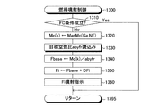
次に、CPU81の実際の作動の詳細について説明する。CPU81は、図13に示した「指示燃料噴射量Fiの計算及び燃料噴射の指示を行うルーチン」を、任意の気筒のクランク角が吸気上死点前の所定クランク角度(例えば、BTDC90°CA)となる毎に、その気筒(以下、「燃料噴射気筒」とも称呼する。)に対して繰り返し実行するようになっている。従って、所定のタイミングになると、CPU81はステップ1300から処理を開始し、ステップ1310にてフューエルカット条件(以下、「FC条件」と表記する。)が成立しているか否かを判定する。
(Actual operation)
<Fuel injection amount control>
Next, details of the actual operation of the
いま、FC条件が成立してないと仮定する。この場合、CPU81は、以下に述べるステップ1320乃至ステップ1360の処理を順に行い、ステップ1395に進んで本ルーチンを一旦終了する。
Assume that the FC condition is not satisfied. In this case, the
ステップ1320:CPU81は、「エアフローメータ61により計測された吸入空気量Ga、クランクポジションセンサ64の信号に基いて取得された機関回転速度NE、及び、ルックアップテーブルMapMc」に基いて「燃料噴射気筒に吸入される空気量」である「筒内吸入空気量Mc(k)」を取得する。筒内吸入空気量Mc(k)は、各吸気行程に対応されながらRAM内に記憶される。筒内吸入空気量Mc(k)は、周知の空気モデル(吸気通路における空気の挙動を模した物理法則に従って構築されたモデル)により算出されてもよい。
Step 1320: The
ステップ1330:CPU81は目標空燃比abyfr(上流側目標空燃比abyfr)を読み込む。目標空燃比abyfrは、図14に示した目標空燃比設定ルーチンにより別途設定されている。図14に示したルーチンについては後述する。
Step 1330: The
ステップ1340:CPU81は、筒内吸入空気量Mc(k)を目標空燃比abyfrで除することにより基本燃料噴射量Fbaseを求める。従って、基本燃料噴射量Fbaseは、目標空燃比abyfrを得るために必要な燃料噴射量のフィードフォワード量である。
Step 1340: The
ステップ1350:CPU81は、基本燃料噴射量Fbaseをメインフィードバック量DFiにより補正する。より具体的には、CPU81は、基本燃料噴射量Fbaseにメインフィードバック量DFiを加えることにより、指示燃料噴射量(最終燃料噴射量)Fiを算出する。メインフィードバック量DFiの算出方法については後述する。
ステップ1360:CPU81は、指示燃料噴射量Fiの燃料を燃料噴射気筒に対応して設けられている燃料噴射弁39から噴射する。
Step 1350: The
Step 1360: The
一方、CPU81がステップ1310の処理を実行する時点において、FC条件が成立していれば、CPU81はそのステップ1310にて「No」と判定し、ステップ1395に直接進んで本ルーチンを一旦終了する。この場合、ステップ1360の処理による燃料噴射が実行されないので、フューエルカット制御(燃料供給停止制御)が実行される。
On the other hand, if the FC condition is satisfied when the
<通常運転時における目標空燃比の設定>
前述したように、CPU81は、図14の目標空燃比設定ルーチンを所定時間が経過する毎に実行するようになっている。いま、今回の機関10の始動後において「応答性増大処理要求の有無」が既に判定され、且つ、応答性増大処理要求が発生しなかったと仮定する。この場合、応答性増大処理要求フラグXreq(以下、「要求フラグXreq」とも称呼する。)の値が「0」に設定される。なお、要求フラグXreqの値は、イニシャルルーチンにおいて「0」に設定されるようになっている。イニシャルルーチンは、機関10が搭載された車両のイグニッション・キー・スイッチ71がオフからオンに変更されたときにCPU81により実行されるルーチンである。
<Setting of target air-fuel ratio during normal operation>
As described above, the
CPU81は、所定のタイミングになると、図14のステップ1400から処理を開始してステップ1405に進み、今回の機関10の始動後において「応答性増大処理要求の有無」が判定済みであるか否かを判定する。
At a predetermined timing, the
前述した仮定に従えば、今回の機関10の始動後において「応答性増大処理要求の有無」が既に判定されている。従って、CPU81はステップ1405にて「Yes」と判定し、以下に述べるステップ1410乃至ステップ1425の処理を順に行い、ステップ1430に進む。
According to the above-mentioned assumption, “the presence / absence of a response increase processing request” has already been determined after the
ステップ1410:CPU81は、フラグXJの値を「0」に設定する。フラグXJは、その値が「1」であるとき、応答性指標値を取得するための処理が実行されていることを示す。なお、フラグXJは上述したイニシャルルーチンにおいて「0」に設定されるようになっている。
ステップ1415:CPU81は、目標空燃比abyfrを理論空燃比stoichに設定する。
ステップ1420:CPU81は、カウンタ実行フラグXCNTの値を「0」に設定する。なお、カウンタ実行フラグXCNTの値は、上述したイニシャルルーチンにおいて「0」に設定されるようになっている。
ステップ1425:CPU81は、カウンタCNTの値を「0」に設定する。なお、カウンタCNTの値は、上述したイニシャルルーチンにおいて「0」に設定されるようになっている。
Step 1410: The
Step 1415: The
Step 1420: The
Step 1425: The
次に、CPU81はステップ1430に進み、要求フラグXreqの値が「1」であるか否かを判定する。前述した仮定に従えば、要求フラグXreqの値は「0」である。従って、CPUはステップ1430にて「No」と判定し、ステップ1495に直接進んで本ルーチンを一旦終了する。以上の処理により、目標空燃比abyfrは理論空燃比stoichに設定される。
Next, the
<メインフィードバック量の算出>
CPU81は図15にフローチャートにより示した「メインフィードバック量算出ルーチン」を所定時間の経過毎に繰り返し実行している。従って、所定のタイミングになると、CPU81はステップ1500から処理を開始し、ステップ1505に進んで「メインフィードバック制御条件(上流側空燃比フィードバック制御条件)」が成立しているか否かを判定する。
<Calculation of main feedback amount>
The
メインフィードバック制御条件は以下の総ての条件が成立したときに成立する。
(A1)空燃比センサ67が活性化している。
(A2)機関の負荷(負荷率)KLが閾値KLth以下である。
(A3)フューエルカット制御中でない。
The main feedback control condition is satisfied when all of the following conditions are satisfied.
(A1) The air-
(A2) The engine load (load factor) KL is less than or equal to the threshold KLth.
(A3) Fuel cut control is not being performed.
なお、負荷率KLは、ここでは下記の(1)式により求められる。この負荷率KLに代え、アクセルペダル操作量Accpが用いられても良い。(1)式において、Mcは筒内吸入空気量であり、ρは空気密度(単位は(g/l))、Lは機関10の排気量(単位は(l))、「4」は機関10の気筒数である。
KL=(Mc/(ρ・L/4))・100% …(1)
Here, the load factor KL is obtained by the following equation (1). Instead of the load factor KL, an accelerator pedal operation amount Accp may be used. In the equation (1), Mc is the in-cylinder intake air amount, ρ is the air density (unit is (g / l)), L is the exhaust amount of the engine 10 (unit is (l)), and “4” is the engine. The number of cylinders is 10.
KL = (Mc / (ρ · L / 4)) · 100% (1)
いま、メインフィードバック制御条件が成立しているものとして説明を続ける。この場合、CPU81はステップ1505にて「Yes」と判定して以下に述べるステップ1510乃至ステップ1540の処理を順に行い、ステップ1595に進んで本ルーチンを一旦終了する。
The description will be continued assuming that the main feedback control condition is satisfied. In this case, the
ステップ1510:CPU81は、下記(2)式に従ってフィードバック制御用出力値Vabyfcを取得する。(2)式において、Vabyfsは空燃比センサ67の出力値、Vafsfbは下流側空燃比センサ68の出力値Voxsに基づいて算出されるサブフィードバック量である。サブフィードバック量Vafsfbの算出方法は周知である。サブフィードバック量Vafsfbは、例えば、下流側空燃比センサ68の出力値Voxsが「理論空燃比に相当する値Vstに設定された下流側目標値Voxsref」よりもリッチ側の空燃比を示す値であるとき減少させられ、下流側空燃比センサ68の出力値Voxsが理論空燃比に相当する値Vstよりもリーン側の空燃比を示す値であるとき増大させられる。なお、CPU81は、サブフィードバック量Vafsfbを「0」に設定してもよい。即ち、CPU81は、サブフィードバック制御を実行しなくてもよい。
Vabyfc=Vabyfs+Vafsfb …(2)
Step 1510: The
Vabyfc = Vabyfs + Vafsfb (2)
ステップ1515:CPU81は、下記(3)式に示したように、上記フィードバック制御用出力値Vabyfcを図4に示したテーブルMapabyfsに適用することにより、フィードバック制御用空燃比abyfscを得る。
abyfsc=Mapabyfs(Vabyfc) …(3)
Step 1515: The
abyfsc = Mapabyfs (Vabyfc) (3)
ステップ1520:CPU81は、下記(4)式に従って、「現時点よりもNサイクル前の時点において燃焼室25に実際に供給された燃料の量」である「筒内燃料供給量Fc(k−N)」を求める。即ち、CPU81は、「現時点よりもNサイクル(即ち、N・720°クランク角)前の時点における筒内吸入空気量Mc(k−N)」を「上記フィードバック制御用空燃比abyfsc」により除すことにより、筒内燃料供給量Fc(k−N)を求める。
Fc(k−N)=Mc(k−N)/abyfsc …(4)
Step 1520: In accordance with the following formula (4), the
Fc (k−N) = Mc (k−N) / abyfsc (4)
このように、筒内燃料供給量Fc(k−N)を求めるために、現時点からNストローク前の筒内吸入空気量Mc(k−N)をフィードバック制御用空燃比abyfscで除すのは、「燃焼室25内での混合気の燃焼により生成された排ガス」が空燃比センサ67に到達するまでに「Nストロークに相当する時間」を要しているからである。
Thus, in order to obtain the in-cylinder fuel supply amount Fc (k−N), the in-cylinder intake air amount Mc (k−N) N strokes before the current stroke is divided by the feedback control air-fuel ratio abyfsc. This is because “a time corresponding to the N stroke” is required until “the exhaust gas generated by the combustion of the air-fuel mixture in the
ステップ1525:CPU81は、下記(5)式に従って、「現時点よりもNサイクル前の時点において燃焼室25に供給されるべきであった燃料の量」である「目標筒内燃料供給量Fcr(k−N)」を求める。即ち、CPU81は、現時点からNストローク前の筒内吸入空気量Mc(k−N)を目標空燃比abyfrで除すことにより、目標筒内燃料供給量Fcr(k−N)を求める。
Fcr=Mc(k−N)/abyfr …(5)
Step 1525: The
Fcr = Mc (k−N) / abyfr (5)
ステップ1530:CPU81は、下記(6)式に従って、筒内燃料供給量偏差DFcを取得する。即ち、CPU81は、目標筒内燃料供給量Fcr(k−N)から筒内燃料供給量Fc(k−N)を減じることにより、筒内燃料供給量偏差DFcを求める。この筒内燃料供給量偏差DFcは、Nストローク前の時点で筒内に供給された燃料の過不足分を表す量となる。
DFc=Fcr(k−N)−Fc(k−N) …(6)
Step 1530: The
DFc = Fcr (k−N) −Fc (k−N) (6)
ステップ1535:CPU81は、下記(7)式に従って、メインフィードバック量DFiを求める。この(7)式において、Gpは予め設定された比例ゲイン、Giは予め設定された積分ゲインである。更に、(7)式の「値SDFc」は「筒内燃料供給量偏差DFcの積分値」である。つまり、CPU81は、フィードバック制御用空燃比abyfscを目標空燃比abyfrに一致させるための比例積分制御により「メインフィードバック量DFi」を算出する。
DFi=Gp・DFc+Gi・SDFc …(7)
Step 1535: The
DFi = Gp · DFc + Gi · SDFc (7)
ステップ1540:CPU81は、その時点における筒内燃料供給量偏差DFcの積分値SDFcに上記ステップ1530にて求められた筒内燃料供給量偏差DFcを加えることにより、新たな筒内燃料供給量偏差の積分値SDFcを取得する。
Step 1540: The
以上により、メインフィードバック量DFiが比例積分制御により求められ、このメインフィードバック量DFiが前述した図13のステップ1350の処理により指示燃料噴射量Fiに反映される。
As described above, the main feedback amount DFi is obtained by the proportional integral control, and this main feedback amount DFi is reflected in the commanded fuel injection amount Fi by the processing of
一方、図15のステップ1505の判定時において、メインフィードバック制御条件が不成立であると、CPU81はそのステップ1505にて「No」と判定してステップ1545に進み、メインフィードバック量DFiの値を「0」に設定する。次いで、CPU81は、ステップ1550にて筒内燃料供給量偏差の積分値SDFcに「0」を格納する。その後、CPU81は、ステップ1595に進んで本ルーチンを一旦終了する。このように、メインフィードバック制御条件が不成立であるとき、メインフィードバック量DFiは「0」に設定される。従って、基本燃料噴射量Fbaseのメインフィードバック量DFiによる補正は行わない。
On the other hand, if the main feedback control condition is not satisfied at the time of determination in
<応答性増大処理要求の有無の判定>
次に、応答性増大処理要求が発生しているか否かを判定する際のCPU81の作動について説明する。応答性増大処理要求が発生しているか否かの判定は、今回の機関10の始動後において「応答性増大処理要求の有無についての判定」がなされていない場合に行われる。従って、以下、今回の機関10の始動後において「応答性増大処理要求の有無についての判定」がなされていないと仮定する。
<Determination of presence / absence of responsiveness increase processing request>
Next, the operation of the
この場合、CPU81が図14のステップ1405に進んだとき、CPU81はそのステップ1405にて「No」と判定してステップ1435に進み、吸入空気量Gaが閾値吸入空気量Gath(例えば、10g/s)以下であるか否かを判定する。このとき、吸入空気量Gaが閾値吸入空気量Gathよりも大きいと、CPU81はステップ1435にて「No」と判定し、ステップ1410以降に進む。この結果、「応答性増大処理要求の有無についての判定」は実行されない。
In this case, when the
一方、CPU81が図14のステップ1435に進んだとき、吸入空気量Gaが閾値吸入空気量Gath以下であると、CPU81はそのステップ1435にて「Yes」と判定してステップ1440に進み、応答性指標値を取得するための処理を開始する。このように、吸入空気量Gaが閾値吸入空気量Gath以下である場合(即ち、低吸入空気量運転時)に応答性指標値を取得するのは、吸入空気量Gaが閾値吸入空気量Gathよりも大きいと、検出空燃比abyfsの変化速度が大きくなり、精度の良い応答性指標値が得られ難いからである。
On the other hand, when the
CPU81は、ステップ1440にてフラグXJの値が「0」であるか否かを判定する。フラグXJの値はイニシャルルーチンにより「0」に設定されている。従って、CPU81はステップ1440にて「Yes」と判定し、以下に述べるステップ1445乃至ステップ1455の処理を順に行い、ステップ1495に進んで本ルーチンを一旦終了する。
In step 1440, the
ステップ1445:CPU81は、目標空燃比abyfrを前述した第1リーン空燃比AFL1に設定する。
ステップ1450:CPU81は、フラグXJの値を「1」に設定する。
ステップ1455:CPU81は、フラグXLの値を「1」に設定する。フラグXLは上述したイニシャルルーチンにおいて「0」に設定されるようになっている。フラグXLは、その値が「1」であるとき、目標空燃比abyfrが第1リーン空燃比AFL1に設定されていることを示す。
Step 1445: The
Step 1450: The
Step 1455: The
この結果、目標空燃比abyfrが第1リーン空燃比AFL1に設定されるので、図13及び図15のルーチンにより機関の空燃比が第1リーン空燃比AFL1へと変更される。 As a result, since the target air-fuel ratio abyfr is set to the first lean air-fuel ratio AFL1, the air-fuel ratio of the engine is changed to the first lean air-fuel ratio AFL1 by the routines of FIGS.
この時点以降、CPU81が図14のルーチンの処理を開始すると、CPU81はステップ1405にて「No」と判定する。更に、吸入空気量Gaが閾値吸入空気量Gath以下である状態が継続していれば、CPU81はステップ1435にて「Yes」と判定してステップ1440に進む。この時点において、フラグXJの値は「1」に設定されている。従って、CPU81はステップ1440にて「No」と判定しステップ1460に進み、フラグXLの値が「0」であるか否かを判定する。この時点において、フラグXLの値は「1」である。従って、CPU81はステップ1460にて「No」と判定し、ステップ1495に直接進んで本ルーチンを一旦終了する。
After this point, when the
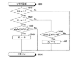
一方、CPU81は、所定時間が経過する毎に図16にフローチャートにより示した「フラグ設定ルーチン」を実行するようになっている。従って、所定のタイミングになると、CPU81は図16のステップ1600から処理を開始してステップ1610に進み、フラグXJの値が「1」であるか否かを判定する。現時点において、フラグXJの値は「1」に設定されている。従って、CPU81はステップ1610にて「Yes」と判定してステップ1620に進み、フラグXLの値が「1」であるか否かを判定する。現時点において、フラグXLの値は「1」に設定されている。従って、CPU81はステップ1620にて「Yes」と判定してステップ1630に進み、検出空燃比abyfsが「第1リーン空燃比AFL1から正の微小値dを減じた値(AFL1−d)」以上となったか否かを判定する。即ち、CPU81は、ステップ1630にて、目標空燃比abyfrが第1リーン空燃比AFL1に設定された後、上流側空燃比センサ67の出力値Vabyfsが第1リーン空燃比AFL1に応じた値に実質的に到達したか否かを判定する。
On the other hand, every time a predetermined time elapses, the
目標空燃比abyfrが第1リーン空燃比AFL1に設定された直後においては、検出空燃比abyfsは値(AFL1−d)よりも小さい。従って、CPU81はステップ1630にて「No」と判定し、ステップ1695に直接進んで本ルーチンを一旦終了する。
Immediately after the target air-fuel ratio abyfr is set to the first lean air-fuel ratio AFL1, the detected air-fuel ratio abyfs is smaller than the value (AFL1-d). Accordingly, the
更に、CPU81は、所定時間が経過する毎に図17にフローチャートにより示した「フラグ設定ルーチン」を実行するようになっている。従って、所定のタイミングになると、CPU81は図17のステップ1700から処理を開始してステップ1710に進み、フラグXJの値が「1」であるか否かを判定する。現時点において、フラグXJの値は「1」に設定されている。従って、CPU81はステップ1710にて「Yes」と判定してステップ1720に進み、フラグXLの値が「0」であるか否かを判定する。現時点において、フラグXLの値は「1」に設定されている。従って、CPU81はステップ1720にて「No」と判定し、ステップ1795に直接進んで本ルーチンを一旦終了する。
Further, the
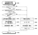
加えて、CPU81は、所定時間が経過する毎に図18にフローチャートにより示した「応答性増大処理要求判定ルーチン」を実行するようになっている。従って、所定のタイミングになると、CPU81は図18のステップ1800から処理を開始してステップ1810に進み、カウンタ実行フラグXCNTの値が「1」であるか否かを判定する。現時点において、カウンタ実行フラグXCNTの値は、上述したイニシャルルーチンにおいて「0」に設定されている。従って、CPU81はステップ1810にて「No」と判定し、ステップ1895に直接進んで本ルーチンを一旦終了する。
In addition, every time a predetermined time elapses, the
この状態(目標空燃比abyfrが第1リーン空燃比AFL1に設定された状態)が継続すると、検出空燃比abyfsは値(AFL1−d)に到達する。このとき、CPU81が図16のルーチンの処理を開始すると、CPU81はステップ1610及びステップ1620にて「Yes」と判定するとともに、ステップ1630にて「Yes」と判定してステップ1640に進み、フラグXLの値を「0」に設定する。その後、CPU81はステップ1695に進み、本ルーチンを一旦終了する。
If this state (state in which the target air-fuel ratio abyfr is set to the first lean air-fuel ratio AFL1) continues, the detected air-fuel ratio abyfs reaches the value (AFL1-d). At this time, when the
この時点以降、CPU81が図14のルーチンの処理を開始すると、CPU81はステップ1405にて「No」と判定する。更に、吸入空気量Gaが閾値吸入空気量Gath以下である状態が継続していれば、CPU81はステップ1435にて「Yes」と判定してステップ1440に進む。この時点において、フラグXJの値は「1」である。従って、CPU81はステップ1440にて「No」と判定してステップ1460に進む。更に、この時点において、フラグXLの値は「0」である。従って、CPU81はステップ1460にて「Yes」と判定してステップ1465に進み、目標空燃比abyfrを前述した第1リッチ空燃比AFR1に設定する。その後、CPU81はステップ1495に直接進んで本ルーチンを一旦終了する。
After this point, when the
この結果、目標空燃比abyfrが第1リッチ空燃比AFR1に設定されるので、図13及び図15のルーチンにより機関の空燃比が第1リッチ空燃比AFR1へと変更される。 As a result, since the target air-fuel ratio abyfr is set to the first rich air-fuel ratio AFR1, the air-fuel ratio of the engine is changed to the first rich air-fuel ratio AFR1 by the routines of FIGS.
この時点以降、CPU81が図17のルーチンの処理を開始すると、CPU81はステップ1710にて「Yes」と判定するとともに、ステップ1720にて「Yes」と判定してステップ1730に進む。そして、CPU81は、ステップ1730にて、現時点が、検出空燃比abyfsが「前述した第2リーン空燃比AFL2(例えば、14.7)」よりも大きい値から「第2リーン空燃比AFL2」よりも小さい値へと変化した時点の直後であるか否かを判定する。
After this point, when the
現時点は、検出空燃比abyfsが値(AFL1−d)に到達した直後であるので、検出空燃比abyfsは「第2リーン空燃比AFL2」に到達していない。従って、CPU81はステップ1730にて「No」と判定し、ステップ1795に直接進んで本ルーチンを一旦終了する。
Since the present time is immediately after the detected air-fuel ratio abyfs reaches the value (AFL1-d), the detected air-fuel ratio abyfs does not reach the “second lean air-fuel ratio AFL2”. Therefore, the
更に、CPU81が図16のルーチンの処理を開始すると、CPU81はステップ1610にて「Yes」と判定するとともに、ステップ1620にて「No」と判定してステップ1650に進む。そして、CPU81は、ステップ1650にて、検出空燃比abyfsが「第1リッチ空燃比AFR1に正の微小値dを加えた値(AFR1+d)」以下となったか否かを判定する。即ち、CPU81は、ステップ1650にて、目標空燃比abyfrが第1リッチ空燃比AFR1に設定された後、上流側空燃比センサ67の出力値Vabyfsが第1リッチ空燃比AFR1に応じた値に実質的に到達したか否かを判定する。
Further, when the
現時点は、検出空燃比abyfsが値(AFL1−d)に到達した直後であるので、検出空燃比abyfsは値(AFR1+d)に到達していない。従って、CPU81はステップ1650にて「No」と判定し、ステップ1695に直接進んで本ルーチンを一旦終了する。
Since the present time is immediately after the detected air-fuel ratio abyfs has reached the value (AFL1-d), the detected air-fuel ratio abyfs has not reached the value (AFR1 + d). Accordingly, the
このような状態が継続すると、上流側空燃比センサ67の出力値Vabyfsは次第に低下するので、検出空燃比abyfsは次第に低下する。その結果、検出空燃比abyfsは、第2リーン空燃比AFL2よりも大きい値から第2リーン空燃比AFL2よりも小さい値へと変化する。従って、この時点の直後に、CPU81が図17のステップ1730の処理を実行すると、CPU81はステップ1730にて「Yes」と判定し、ステップ1740に進んでカウンタ実行フラグXCNTの値を「1」に設定する。更に、CPU81はステップ1750に進み、カウンタCNTの値を「0」に設定し、ステップ1795に進んで本ルーチンを一旦終了する。
If such a state continues, the output value Vabyfs of the upstream side air-
これにより、CPU81は図18のステップ1810に進んだとき、そのステップ1810にて「Yes」と判定してステップ1820に進み、カウンタCNTの値を「1」だけ増大する。即ち、カウンタCNTがインクリメントされる。次いで、CPU81はステップ1830に進み、現時点が、検出空燃比abyfsが「前述した第2リッチ空燃比AFR2(例えば、14.5)」よりも大きい値から「第2リッチ空燃比AFR2」よりも小さい値へと変化した時点の直後であるか否かを判定する。
Thereby, when the
現時点は、検出空燃比abyfsが「第2リーン空燃比AFL2」に到達した直後である。従って、検出空燃比abyfsは第2リッチ空燃比AFR2に到達していない。従って、CPU81はステップ1830にて「No」と判定し、ステップ1895に直接進んで本ルーチンを一旦終了する。
The present time is immediately after the detected air-fuel ratio abyfs reaches the “second lean air-fuel ratio AFL2”. Therefore, the detected air-fuel ratio abyfs has not reached the second rich air-fuel ratio AFR2. Therefore, the
この状態が継続すると、カウンタCNTの値はステップ1820の処理により次第に増大する。更に、検出空燃比abyfsは次第に低下し、第2リッチ空燃比AFR2よりも大きい値から第2リッチ空燃比AFR2よりも小さい値へと変化する。従って、この時点の直後に、CPU81が図18のステップ1830の処理を実行すると、CPU81はステップ1830にて「Yes」と判定し、ステップ1840に進んでカウンタ実行フラグXCNTの値を「0」に設定する。これにより、カウンタCNTのインクリメントが停止する。即ち、カウンタCNTの値は、目標空燃比abyfrが第1リーン空燃比AFL1から第1リッチ空燃比AFR1に変更された時点以降において、検出空燃比abyfsが第2リーン空燃比AFL2から第2リッチ空燃比AFR2にまで変化するのに要する時間(前述した第1の応答時間)を表す。換言すると、カウンタCNTの値は応答性指標値である。
If this state continues, the value of the counter CNT is gradually increased by the processing in
次に、CPU81はステップ1850に進み、カウンタCNTの値が所定の閾値CNTth以上であるか否かを判定する。このとき、カウンタCNTの値が所定の閾値CNTth以上であれば、上流側空燃比センサ67の出力応答性が許容応答性未満であるので、CPU81はステップ1850にて「Yes」と判定し、ステップ1860に進んで要求フラグXreqの値を「1」に設定する。これに対し、カウンタCNTの値が所定の閾値CNTth未満であれば、上流側空燃比センサ67の出力応答性は許容応答性以上であるので、CPU81はステップ1850にて「No」と判定し、ステップ1895に直接進んで本ルーチンを一旦終了する。この結果、要求フラグXreqの値は「0」に維持される。このステップ1850の処理が実行されたことは、「応答性増大処理要求の有無」の判定がなされたことを意味する。
Next, the
この状態においては、目標空燃比abyfrは依然として第1リッチ空燃比AFR1である。従って、所定の時間が経過すると、上流側空燃比センサ67の出力値Vabyfsは第1リッチ空燃比AFR1に応じた値に実質的に到達する。即ち、検出空燃比abyfsは、値(AFL1+d)」以下となる。このとき、CPU81が図16のステップ1650の処理を実行すると、CPU81はそのステップ1650にて「Yes」と判定し、ステップ1660に進んでフラグXJの値を「0」に設定する。
In this state, the target air-fuel ratio abyfr is still the first rich air-fuel ratio AFR1. Therefore, when the predetermined time has elapsed, the output value Vabyfs of the upstream air-
この結果、CPU81は図16のステップ1610にて「No」と判定し、ステップ1695に直接進むようになる。同様に、CPU81は図17のステップ1710にて「No」と判定し、ステップ1795に直接進むようになる。
As a result, the
更に、この時点以降、CPU81が図14のステップ1405に進んだとき、「応答性増大処理要求の有無」は判定済みであるから、CPU81はステップ1405にて「Yes」と判定し、ステップ1410乃至ステップ1425の処理を実行し、ステップ1430に進む。
Further, after this time point, when the
いま、図18のステップ1860にて要求フラグXreqの値が「1」に設定されたと仮定する。この場合、CPU81はステップ1430にて「Yes」と判定してステップ1470に進み、機関10の現時点の運転状態がアイドル運転状態であるか否かを判定する。例えば、CPU81は、スロットル弁開度TAが「0」であり、且つ、機関回転速度NEが所定回転速度以下であるとき、機関10の現時点の運転状態がアイドル運転状態であると判定する。
Now, it is assumed that the value of the request flag Xreq is set to “1” in
そして、現時点の運転状態がアイドル運転状態であると、CPU81はステップ1470にて「Yes」と判定してステップ1475に進み、目標空燃比abyfrを「理論空燃比stoichよりも僅かに小さい(リッチな)アイドル時リッチ空燃比AFidlerich」に設定する。この結果、アイドル運転状態における機関の空燃比が、理論空燃比よりもリッチな空燃比になる。その後、CPU81はステップ1495に進み、本ルーチンを一旦終了する。また、CPU81がステップ1470の処理を実行する時点において、現時点の運転状態がアイドル運転状態でなければ、CPU81はステップ1470にて「No」と判定し、ステップ1495に直接進んで本ルーチンを一旦終了する。この結果、目標空燃比abyfrは理論空燃比stoichに維持される(ステップ1415を参照。)。
If the current operation state is the idle operation state, the
<応答性増大処理>
次に、応答性増大処理について説明する。CPU81は、CPUは、機関10の運転停止後、所定時間が経過する毎に図19にフローチャートにより示した「応答性増大処理ルーチン」を実行するようになっている。なお、CPU81は、イグニッション・キー・スイッチ71がオフ位置に設定されると、機関10の運転が停止したと判定する。
<Response increase processing>
Next, the response increase process will be described. The
機関10の運転停止後において所定のタイミングになると、CPUは図19のステップ1900から処理を開始してステップ1905に進み、要求フラグXreqの値が「1」であるか否かを判定する。
When the predetermined timing comes after the operation of the
いま、空燃比センサ67の出力応答性が低いために、図18のステップ1860にて要求フラグXreqの値が「1」に設定されていると仮定する。この場合、CPU81はステップ1905にて「Yes」と判定し、ステップ1910に進んで検出空燃比abyfsが理論空燃比stoichよりも小さい(リッチ)か否かを判定する。
Now, since the output responsiveness of the air-
前述したように、要求フラグXreqの値が「1」に設定された場合、図14のステップ1470及びステップ1475の処理により、アイドル運転状態における目標空燃比abyfrはアイドル時リッチ空燃比AFidlerichに設定される。更に、一般に、機関10の状態が運転状態から停止状態へと移行する際、機関10の状態はアイドル運転状態を経てから停止状態へと到る。従って、要求フラグXreqの値が「1」に設定された場合、機関10の運転停止直後において上流側空燃比センサ67の周囲に存在するガスの空燃比は理論空燃比よりも小さいリッチ空燃比である。
As described above, when the value of the request flag Xreq is set to “1”, the target air-fuel ratio abyfr in the idling operation state is set to the idling rich air-fuel ratio AFidlerich by the processing of
従って、CPU81はステップ1910にて「Yes」と判定してステップ1915に進み、車両に搭載されたバッテリの状態が良好であるか否かを判定する。例えば、CPU81は、ステップ1915にて、バッテリ電圧センサ72により検出されたバッテリ電圧VBが閾値電圧VBth以上であるときにバッテリの状態が良好であると判定する。なお、CPU81は、図示しないバッテリ残量センサの出力に基いてバッテリの状態が良好であるか否かを判定してもよい。
Accordingly, the
いま、バッテリの状態が良好であると仮定する。この場合、CPU81はステップ1915にて「Yes」と判定し、以下に述べるステップ1920乃至ステップ1930の処理(応答性増大処理)を順に行い、ステップ1995に進んで本ルーチンを一旦終了する。
Assume that the battery is in good condition. In this case, the
ステップ1920:CPU81は、上流側空燃比センサ67の排ガス側電極層672と大気側電極層673との間にセンサ応答性増大用電圧Vupを印加する。
ステップ1925:CPU81は、空燃比センサ素子温度が応答性増大用温度となるように、ヒータ678の通電量を制御する。
ステップ1930:機関10が上流側空燃比センサ67と上流側触媒53との間に排気制御弁を備えている場合、CPU81はその排気制御弁を閉弁する。
この結果、上述したように、上流側空燃比センサ67の出力応答性が向上(回復)する。
Step 1920: The
Step 1925: The
Step 1930: When the
As a result, as described above, the output response of the upstream air-
その後、CPU81はステップ1910の処理を繰り返し実行するようになる。従って、所定時間が経過して上流側空燃比センサ67の周囲のリッチガスが消失すると、CPU81はステップ1910にて「No」と判定し、以下に述べるステップ1935乃至ステップ1950の処理を順に行い、ステップ1995に進んで本ルーチンを一旦終了する。
Thereafter, the
ステップ1935:CPU81は、上流側空燃比センサ67の排ガス側電極層672と大気側電極層673との間への電圧の印加を停止する。
ステップ1940:CPU81は、ヒータ678の通電量を「0」に設定する。即ち、ヒータ678をオフする。
ステップ1945:機関10が上流側空燃比センサ67と上流側触媒53との間に排気制御弁を備えている場合、CPU81はその排気制御弁を開弁する。
ステップ1950:CPU81は、要求フラグXreqの値を「0」に設定する。
この結果、応答性増大処理が終了する。
Step 1935: The
Step 1940: The
Step 1945: When the
Step 1950: The
As a result, the responsiveness increasing process ends.
なお、CPU81は、ステップ1905に進んだときに要求フラグXreqの値が「1」でない場合、そのステップ1905にて「No」と判定し、ステップ1935乃至ステップ1950の処理を実行する。更に、CPU81は、ステップ1915に進んだときにバッテリの状態が良好でなければ、ステップ1935乃至ステップ1950の処理を実行する。
If the value of the request flag Xreq is not “1” when the process proceeds to step 1905, the
<空燃比気筒間インバランス判定>
次に、「空燃比気筒間インバランス判定」を実行するための処理について説明する。CPU81は、機関10の運転中において4ms(所定の一定サンプリング時間ts)が経過する毎に、図20にフローチャートにより示した「空燃比気筒間インバランス判定ルーチン」を実行するようになっている。
<Air-fuel ratio imbalance determination between cylinders>
Next, a process for executing the “air-fuel ratio imbalance determination between cylinders” will be described. The
従って、所定のタイミングになると、CPU81はステップ2000から処理を開始してステップ2005に進み、判定許可フラグXkyokaの値が「1」であるか否かを判定する。
Therefore, when the predetermined timing comes, the
この判定許可フラグXkyokaの値は、絶対クランク角CAが0°クランク角になった時点において後述する判定実行条件が成立しているときに「1」に設定され、判定実行条件が不成立になった時点において直ちに「0」に設定される。 The value of the determination permission flag Xkyoka is set to “1” when a determination execution condition described later is satisfied when the absolute crank angle CA becomes 0 ° crank angle, and the determination execution condition is not satisfied. It is immediately set to “0” at the time.
判定実行条件は、以下の総ての条件(条件C0乃至条件C3)が成立したときに成立する。即ち、判定実行条件は、以下の総ての条件(条件C0乃至条件C3)のうちの少なくとも一つが不成立であるとき、成立しない。なお、条件C0及び/又は条件C1は省略されてもよい。 The determination execution condition is satisfied when all of the following conditions (condition C0 to condition C3) are satisfied. That is, the determination execution condition is not satisfied when at least one of the following conditions (conditions C0 to C3) is not satisfied. Note that the condition C0 and / or the condition C1 may be omitted.
(条件C0)今回の機関10の始動後、空燃比気筒間インバランス判定が一度もなされていない。この条件C0は、インバランス判定実施要求条件とも称呼される。条件C0は、前回のインバランス判定からの「機関10の運転時間の積算値、又は、吸入空気量Gaの積算値、が所定値以上である。」ことに置換されてもよい。
(Condition C0) The air-fuel ratio imbalance among cylinders has never been determined after the
(条件C1)エアフローメータ61により取得される吸入空気量Gaが、第1閾値空気流量Ga1thよりも大きい状態が第1閾値時間T1th以上継続している。即ち、吸入空気量Gaが第1閾値空気流量Ga1thよりも大きく、且つ、吸入空気量Gaが第1閾値空気流量Ga1th以下から第1閾値空気流量Ga1thよりも大きくなった時点からの経過時間が第1閾値時間T1th以上である。
(Condition C1) The state where the intake air amount Ga acquired by the
(条件C2)メインフィードバック制御条件が成立し、且つ、目標空燃比abyfrが理論空燃比stoichである。
(条件C3)フューエルカット制御中でない。
(Condition C2) The main feedback control condition is satisfied, and the target air-fuel ratio abyfr is the stoichiometric air-fuel ratio stoich.
(Condition C3) Fuel cut control is not being performed.
いま、判定許可フラグXkyokaの値が「1」であると仮定する。この場合、CPU81はステップ2005にて「Yes」と判定し、ステップ2010に進んで「その時点の空燃比センサ67の出力値Vabyfs」をAD変換することにより取得する。
Assume that the value of the determination permission flag Xkyoka is “1”. In this case, the
次に、CPU81はステップ2015に進み、ステップ2010にて取得した出力値Vabyfsを図4に示した空燃比変換テーブルMapabyfsに適用することにより、今回の検出空燃比abyfsを取得する。なお、CPU81は、ステップ2015の処理の前に、本ルーチンを前回実行したときに取得した検出空燃比abyfsを前回の検出空燃比abyfsoldとして記憶する。即ち、前回の検出空燃比abyfsoldは、現時点から4ms(サンプリング時間ts)前の時点における検出空燃比abyfsである。前回の検出空燃比abyfsoldの初期値は、上述したイニシャルルーチンにおいて理論空燃比相当値VstoichのAD変換値に相当する値に設定されている。
Next, the
次に、CPU81はステップ2020に進んで、
(A)検出空燃比変化率ΔAFを取得し、
(B)検出空燃比変化率ΔAFの絶対値|ΔAF|の積算値SAFDを更新し、
(C)検出空燃比変化率ΔAFの絶対値|ΔAF|の、積算値SAFDへの積算回数カウンタCnを更新する。
以下、これらの更新方法について具体的に説明する。
Next, the
(A) Obtain the detected air-fuel ratio change rate ΔAF,
(B) update the integrated value SAFD of the absolute value | ΔAF | of the detected air-fuel ratio change rate ΔAF;
(C) Update the integration number counter Cn of the absolute value | ΔAF | of the detected air-fuel ratio change rate ΔAF to the integrated value SAFD.
Hereinafter, these update methods will be described in detail.
(A)検出空燃比変化率ΔAFの取得。
検出空燃比変化率ΔAFは、インバランス判定用パラメータの元データとなるデータ(基本指標量)である。CPU81は、この検出空燃比変化率ΔAFを、今回の検出空燃比abyfsから前回の検出空燃比abyfsoldを減じることによって取得する。即ち、今回の検出空燃比abyfsをabyfs(n)、前回の検出空燃比abyfsoldをabyfs(n−1)と表記すると、CPU81はステップ2020にて「今回の検出空燃比変化率ΔAF(n)」を下記の(8)式に従って求める。検出空燃比変化率ΔAFは、検出空燃比abyfsの微分値d(abyfs)/dtに相当する値である。
ΔAF(n)=abyfs(n)−abyfs(n−1) …(8)
(A) Acquisition of detected air-fuel ratio change rate ΔAF.
The detected air-fuel ratio change rate ΔAF is data (basic index amount) that is the original data of the imbalance determination parameter. The
ΔAF (n) = abyfs (n) −abyfs (n−1) (8)
(B)検出空燃比変化率ΔAFの絶対値|ΔAF|の積算値SAFDの更新。
CPU81は今回の積算値SAFD(n)を下記の(9)式に従って求める。即ち、CPU81は、ステップ2020に進んだ時点における前回の積算値SAFD(n−1)に上記算出した今回の検出空燃比変化率ΔAF(n)の絶対値|ΔAF(n)|を加えることにより、積算値SAFDを更新する。
SAFD(n)=SAFD(n−1)+|ΔAF(n)|…(9)
(B) Updating the integrated value SAFD of the absolute value | ΔAF | of the detected air-fuel ratio change rate ΔAF.
The
SAFD (n) = SAFD (n−1) + | ΔAF (n) | (9)
積算値SAFDに「今回の検出空燃比変化率の絶対値|ΔAF(n)|」を積算する理由は、図5の(B)及び(C)からも理解されるように、検出空燃比変化率ΔAF(n)は正の値にも負の値にもなるからである。なお、積算値SAFDも、イニシャルルーチンにおいて「0」に設定されるようになっている。 The reason why the “absolute value of the detected air-fuel ratio change rate | ΔAF (n) |” is added to the integrated value SAFD is, as will be understood from FIGS. 5B and 5C, the detected air-fuel ratio change. This is because the rate ΔAF (n) can be a positive value or a negative value. The integrated value SAFD is also set to “0” in the initial routine.
(C)検出空燃比変化率ΔAFの絶対値|ΔAF|の、積算値SAFDへの積算回数カウンタCnの更新。
CPU81は、下記の(10)式に従って、カウンタCnの値を「1」だけ増大する。Cn(n)は更新後のカウンタCnであり、Cn(n−1)は更新前のカウンタCnである。このカウンタCnの値は上述したイニシャルルーチンにおいて「0」に設定されるとともに、後述するステップ2065にても「0」に設定される。従って、カウンタCnの値は、積算値SAFDに積算された検出空燃比変化率ΔAFの絶対値|ΔAF|のデータ数を示す。
Cn(n)=Cn(n−1)+1 …(10)
(C) Update of the integration number counter Cn to the integrated value SAFD of the absolute value | ΔAF | of the detected air-fuel ratio change rate ΔAF.
The
Cn (n) = Cn (n−1) +1 (10)
次に、CPU81はステップ2025に進み、基準気筒(本例では第1気筒)の圧縮上死点を基準としたクランク角CA(絶対クランク角CA)が720°クランク角になっているか否かを判定する。このとき、絶対クランク角CAが720°クランク角未満であると、CPU81はステップ2025にて「No」と判定してステップ2095に直接進み、本ルーチンを一旦終了する。
Next, the
なお、ステップ2025は、検出空燃比変化率ΔAFの絶対値|ΔAF|の平均値を求めるための最小単位の期間(単位燃焼サイクル期間)を定めるステップであり、ここでは720°クランク角がその最小期間に相当する。もちろん、この最小期間は720°クランク角よりも短くてもよいが、サンプリング時間tsの複数倍の長さ以上の期間であることが望ましい。即ち、最小単位の期間内に複数個の検出空燃比変化率ΔAFが取得されるように、その最小単位の期間が定められていることが望ましい。
一方、CPU81がステップ2025の処理を行う時点において、絶対クランク角CAが720°クランク角になっていると、CPU81はそのステップ2025にて「Yes」と判定し、ステップ2030に進む。
On the other hand, if the absolute crank angle CA is 720 ° crank angle when the
CPU81は、ステップ2030にて、
(D)検出空燃比変化率ΔAFの絶対値|ΔAF|の平均値AveΔAFを算出し、
(E)平均値AveΔAFの積算値Saveを更新し、
(F)積算回数カウンタCsを更新する。
を行う。以下、これらの更新方法について具体的に説明する。
In
(D) calculating an average value AveΔAF of the absolute value | ΔAF | of the detected air-fuel ratio change rate ΔAF;
(E) Update the integrated value Save of the average value AveΔAF,
(F) Update the cumulative number counter Cs.
I do. Hereinafter, these update methods will be described in detail.
(D)検出空燃比変化率ΔAFの絶対値|ΔAF|の平均値AveΔAFの算出。
CPU81は、積算値SAFDをカウンタCnの値により除することにより、検出空燃比変化率ΔAFの絶対値|ΔAF|の平均値AveΔAF(=SAFD/Cn)を算出する。この後、CPU81は積算値SAFDを「0」に設定するとともに、カウンタCnの値を「0」に設定する。
(D) Calculation of the average value AveΔAF of the absolute value | ΔAF | of the detected air-fuel ratio change rate ΔAF.
The
(E)平均値AveΔAFの積算値Saveの更新。
CPU81は今回の積算値Save(n)を下記の(11)式に従って求める。即ち、CPU81は、ステップ2030に進んだ時点における前回の積算値Save(n−1)に上記算出した今回の平均値AveΔAFを加えることにより、積算値Saveを更新する。この積算値Saveの値は上述したイニシャルルーチンにおいて「0」に設定される。
Save(n)=Save(n−1)+AveΔAF …(11)
(E) Update of the integrated value Save of the average value AveΔAF.
CPU81 calculates | requires this integrated value Save (n) according to following (11) Formula. That is, the
Save (n) = Save (n−1) + AveΔAF (11)
(F)積算回数カウンタCsの更新。
CPU81は、下記の(12)式に従って、カウンタCsの値を「1」だけ増大する。Cs(n)は更新後のカウンタCsであり、Cs(n−1)は更新前のカウンタCsである。このカウンタCsの値は上述したイニシャルルーチンにおいて「0」に設定される。従って、カウンタCsの値は、積算値Saveに積算された平均値AveΔAFのデータ数を示す。
Cs(n)=Cs(n−1)+1 …(12)
(F) Update of the cumulative number counter Cs.
The
Cs (n) = Cs (n−1) +1 (12)
次に、CPU81はステップ2035に進み、カウンタCsの値が閾値Csth以上であるか否かを判定する。このとき、カウンタCsの値が閾値Csth未満であると、CPU81はそのステップ2035にて「No」と判定し、ステップ2095に直接進んで本ルーチンを一旦終了する。なお、閾値Csthは自然数であり、2以上であることが望ましい。
Next, the
一方、CPU81がステップ2035の処理を行う時点において、カウンタCsの値が閾値Csth以上であると、CPU81はそのステップ2035にて「Yes」と判定し、以下に述べるステップ2040及びステップ2045の処理を順に行い、ステップ2050に進む。
On the other hand, if the value of the counter Cs is equal to or greater than the threshold value Csth at the time when the
ステップ2040:CPU81は、下記(13)式に従って積算値SaveをカウンタCsの値(=Csth)によって除することにより、空燃比変動指標量AFDを取得する。この空燃比変動指標量AFDは、検出空燃比変化率ΔAFの絶対値|ΔAF|の各単位燃焼サイクル期間における平均値を、複数(Csth分)の単位燃焼サイクル期間について平均した値である。なお、CPU81は、空燃比変動指標量AFDを取得した後、積算値Save及びカウンタCsの値を「0」に設定する。
AFD=Save/Csth …(13)
Step 2040: The
AFD = Save / Csth (13)
ステップ2045:CPU81は、空燃比変動指標量AFDをインバランス判定用パラメータXとして採用(格納)する。
Step 2045: The
CPU81は、ステップ2045に続いてステップ2050に進み、インバランス判定用パラメータXがインバランス判定用閾値Xthよりも大きいか否かを判定する。
The
このとき、インバランス判定用パラメータXがインバランス判定用閾値Xthよりも大きいと、CPU81はステップ2050にて「Yes」と判定してステップ2055に進み、インバランス発生フラグXIMBの値を「1」に設定する。即ち、CPU81は空燃比気筒間インバランス状態が発生していると判定する。更に、このとき、CPU81は図示しない警告ランプを点灯してもよい。なお、インバランス発生フラグXIMBの値はバックアップRAM84に格納される。その後、CPU81はステップ2095に進んで本ルーチンを一旦終了する。
At this time, if the imbalance determination parameter X is larger than the imbalance determination threshold value Xth, the
これに対し、CPU81がステップ2050の処理を行う時点において、インバランス判定用パラメータXがインバランス判定用閾値Xth以下であると、CPU81はステップ2050にて「No」と判定してステップ2060に進み、インバランス発生フラグXIMBの値を「2」に設定する。即ち、「空燃比気筒間インバランス判定の結果、空燃比気筒間インバランス状態が発生していないと判定された旨」を記憶する。その後、CPU81はステップ2095に進んで本ルーチンを一旦終了する。なお、ステップ2060は省略されてもよい。
On the other hand, if the imbalance determination parameter X is equal to or less than the imbalance determination threshold value Xth when the
一方、CPU81がステップ2005に進んだ際に判定許可フラグXkyokaの値が「1」でなければ、CPU81はそのステップ2005にて「No」と判定してステップ2065に進む。そして、CPU81はステップ2065にて各値(例えば、ΔAF,SAFD,Cn等)を「0」に設定(クリア)し、その後、ステップ2095に直接進んで本ルーチンを一旦終了する。
On the other hand, if the value of the determination permission flag Xkyoka is not “1” when the
以上、説明したように、本発明の実施形態に係る内燃機関の制御装置は、
空燃比検出用電圧Vpが印加されたときに固体電解質層671を流れる限界電流Ipに基いて「空燃比センサ67が配設された部位を通過する排ガスの空燃比」に応じた出力値Vabyfsを出力する空燃比センサ67と、
空燃比検出用電圧Vpを印加する空燃比検出用電圧印加手段(電源679)と、
複数の気筒のそれぞれに対応して配設される複数の燃料噴射弁39と、
「空燃比検出用電圧が印加されている場合の空燃比センサ67の出力値Vabyfsにより表される空燃比(検出空燃比abyfs)」と「理論空燃比に設定された目標空燃比abyfr」とが一致するように、燃料噴射弁39から噴射される燃料噴射量をフィードバック制御する空燃比フィードバック制御手段(図13のステップ1350及び図15を参照。)と、
フィードバック制御が実行されている期間において空燃比センサ67が配設された部位を通過する排ガスの空燃比の変動が大きくなるほど大きくなるインバランス判定用パラメータXを、空燃比センサ67の出力値Vabyfsに基づいて取得するとともに(図20のステップ2005乃至ステップ2045を参照。)、インバランス判定用パラメータXが所定のインバランス判定用閾値Xthよりも大きいとき空燃比気筒間インバランス状態が発生したと判定するインバランス判定手段(図20のステップ2050乃至ステップ2060を参照。)と、
「空燃比センサ67が配設された部位を通過する排ガスの空燃比」が理論空燃比を横切るように変化する場合における「空燃比センサ出力値の変化速度に応じた応答性指標値CNT」を、空燃比センサ67の出力値Vabyfsに基いて取得するとともに(図14のステップ1440乃至ステップ1465、図16、図17及び図18を参照。)、前記応答性指標値CNTと所定の閾値CNTthとを比較することにより空燃比センサ67の出力応答性が許容応答性未満であるか否かを判定する(図18のステップ1850を参照。)応答性判定手段と、
空燃比センサの出力応答性が許容応答性未満であると判定された場合(要求フラグXreq=1)、排ガス側電極層672の電位よりも大気側電極層673の電位が高くなるように、排ガス側電極層672と大気側電極層673との間に「空燃比検出用電圧Vpよりも大きいセンサ応答性増大用電圧Vup」を印加することにより、空燃比センサ67の出力応答性を向上させるための応答性増大処理を実行する応答性増大処理実行手段(図19のステップ1920を参照。)と、
を備える。
As described above, the control device for an internal combustion engine according to the embodiment of the present invention is
Based on the limit current Ip flowing through the
Air-fuel ratio detection voltage applying means (power supply 679) for applying the air-fuel ratio detection voltage Vp;
A plurality of
"The air-fuel ratio (detected air-fuel ratio abyfs) represented by the output value Vabyfs of the air-
The imbalance determination parameter X, which increases as the fluctuation of the air-fuel ratio of the exhaust gas that passes through the portion where the air-
“Responsiveness index value CNT according to change rate of air-fuel ratio sensor output value” when “the air-fuel ratio of exhaust gas passing through the portion where the air-
When it is determined that the output responsiveness of the air-fuel ratio sensor is less than the allowable responsiveness (request flag Xreq = 1), the exhaust gas so that the potential of the atmosphere
Is provided.
従って、応答性増大処理により空燃比センサ67の出力応答性が増大するので、インバランス判定用パラメータXが「空燃比気筒間インバランス状態の程度」を精度良く表す値になる。その結果、インバランス判定を精度良く行うことができる。
Accordingly, since the output response of the air-
しかも、応答性増大処理は、空燃比センサ67の出力応答性が許容応答性未満である場合に実行され、空燃比センサ67の出力応答性が許容応答性以上である場合には実行されない。この結果、無駄に電力を消費すること及び/又は空燃比センサ67が劣化することを回避することができる。
Moreover, the responsiveness increasing process is executed when the output responsiveness of the air-
更に、応答性増大処理は、機関10の運転停止後に実行される(図19のルーチンが実行されるタイミングを参照。)。
Further, the responsiveness increasing process is executed after the operation of the
加えて、制御装置は、応答性増大処理を行う必要がある場合、「機関10の運転停止後において空燃比センサ67の周囲に存在する排ガスの空燃比」が「理論空燃比よりも小さい空燃比」となるように、機関10の運転停止前において燃料噴射弁39から噴射される燃料噴射量を制御する(図14のステップ1430、ステップ1470及びステップ1475と、図13のステップ1340と、を参照。)。従って、空燃比センサ67の出力応答性をより効率的に向上することができる。
In addition, when the control device needs to perform responsiveness increasing processing, “the air-fuel ratio of the exhaust gas existing around the air-
なお、上記制御装置は、アイドル運転時における目標空燃比abyfrを空燃比AFidlerich」に設定することにより、「機関10の運転停止後において空燃比センサ67の周囲に存在する排ガスの空燃比」を「理論空燃比よりも小さい空燃比」に制御した。これに代え、上記制御装置は、サブフィードバック量を算出する際に用いられる下流側目標値Voxsrefを、理論空燃比よりも僅かにリッチ側の空燃比に相当する値(値Vstよりも大きい値)に設定することにより、「機関10の運転停止後において空燃比センサ67の周囲に存在する排ガスの空燃比」を「理論空燃比よりも小さい空燃比」に制御してもよい。
The control device sets the target air-fuel ratio abyfr at the time of idle operation to the air-fuel ratio AFidlerich, thereby setting the “air-fuel ratio of the exhaust gas existing around the air-
また、制御装置は、応答性増大処理を行う必要がある場合、機関10の停止後において固体電解質層671の温度(空燃比センサ素子温度)が、機関10の運転中における固体電解質層671の温度よりも高い温度になるように、ヒータ678へ電力を供給するように構成されている(図19のステップ1925を参照。)。従って、空燃比センサ67の出力応答性をより効率的に向上することができる。
Further, when the control device needs to perform responsiveness increasing processing, the temperature of the solid electrolyte layer 671 (air-fuel ratio sensor element temperature) after the stop of the
なお、図19のステップ1925乃至ステップ1930の処理は省略され得る。即ち、応答性増大処理は、排ガス側電極層672と大気側電極層673との間に「空燃比検出用電圧よりも大きいセンサ応答性増大用電圧Vup」を印加することのみからなっていてもよい。更に、制御装置は、「機関10の運転停止後において空燃比センサ67の周囲に存在する排ガスの空燃比」を「理論空燃比よりも小さい空燃比」に制御しなくてもよい。即ち、排ガス側電極層672と大気側電極層673との間に「空燃比検出用電圧Vpよりも大きいセンサ応答性増大用電圧Vup」を印加することのみによっても、空燃比センサ67の出力応答性は改善される。
Note that the processing from
更に、上記制御装置は、応答性指標値として、「空燃比センサ67が配設された部位を通過する排ガスの空燃比」が「理論空燃比よりも大きい第1リーン空燃比AFL1」から「理論空燃比よりも小さい第1リッチ空燃比AFR1」へと変化した場合において、「空燃比センサ67の出力値Vabyfsにより表される検出空燃比abyfs」が「理論空燃比よりも大きく且つ第1リーン空燃比AFL1よりも小さい第2リーン空燃比AFL2」から「理論空燃比よりも小さく且つ第1リッチ空燃比AFR1よりも大きい第2リッチ空燃比AFR2」へと変化するまでの時間(第1の応答時間)に基く値CNTを取得した。
Further, the control device uses, as the response index value, “the first lean air-fuel ratio AFL1 where the air-fuel ratio of the exhaust gas passing through the portion where the air-
これに代え或いはこれに加え、上記制御装置は、応答性指標値として、「空燃比センサ67が配設された部位を通過する排ガスの空燃比」が「理論空燃比よりも小さい第3リッチ空燃比AFR3」から「理論空燃比よりも大きい第3リーン空燃比AFL3」へと変化した場合において、「空燃比センサ67の出力値Vabyfsにより表される検出空燃比abyfs」が「理論空燃比よりも小さく且つ第3リッチ空燃比AFR3よりも大きい第4リッチ空燃比AFR4」から「理論空燃比よりも大きく且つ第3リーン空燃比AFL3よりも小さい第4リーン空燃比AFL4」へと変化するまでの時間(第2の応答時間)に基く値を取得してもよい。
Instead of this, or in addition to this, the control device uses, as a responsiveness index value, “a third rich air condition in which“ the air-fuel ratio of the exhaust gas that passes through the portion where the air-
この場合、第3リッチ空燃比AFR3と第1リッチ空燃比AFR1は同じであっても相違していてもよい。第3リーン空燃比AFL3と第1リーン空燃比AFL1は同じであっても相違していてもよい。第4リッチ空燃比AFR4は第2リッチ空燃比AFR2と同じであっても相違していてもよい。第4リーン空燃比AFL4は第2リーン空燃比AFL2と同じであっても相違していてもよい。 In this case, the third rich air-fuel ratio AFR3 and the first rich air-fuel ratio AFR1 may be the same or different. The third lean air-fuel ratio AFL3 and the first lean air-fuel ratio AFL1 may be the same or different. The fourth rich air-fuel ratio AFR4 may be the same as or different from the second rich air-fuel ratio AFR2. The fourth lean air-fuel ratio AFL4 may be the same as or different from the second lean air-fuel ratio AFL2.
更に、上記制御装置は、応答性指標値として、前記第1の応答時間及び前記第2の応答時間に基づいて得られる値(例えば、第1の応答時間及び第2の応答時間の平均値)を取得してもよい。 Further, the control device may obtain a value obtained based on the first response time and the second response time as a responsiveness index value (for example, an average value of the first response time and the second response time). May be obtained.
また、上記制御装置は、応答性指標値として、「空燃比センサ67が配設された部位を通過する排ガスの空燃比」が「理論空燃比よりも大きい第1リーン空燃比AFL1」から「理論空燃比よりも小さい第1リッチ空燃比AFR1」へ、又は、その逆へ、と変化した場合における「検出空燃比abyfsの微分値d(abyfs)/dt(又は、出力値Vabyfsの微分値d(Vabyfs)/dt)」に相関する値(例えば、検出空燃比abyfsが第2リーン空燃比AFL2から第2リッチ空燃比AFR2に至る期間において所定時間の経過毎に取得される微分値d(abyfs)/dtの平均値等)を取得してもよい。即ち、応答性指標値は、「空燃比センサ67が配設された部位を通過する排ガスの空燃比」が理論空燃比を横切るように変化する場合における「空燃比センサ67の出力値Vabyfsが理論空燃比に相当する値を横切る際の出力値Vabyfs又は検出空燃比abyfsの変化速度」に応じた値であればよい。
Further, the control device uses, as the response index value, “the first lean air-fuel ratio AFL1 where the air-fuel ratio of the exhaust gas passing through the portion where the air-
加えて、上記制御装置は、目標空燃比abyfrを「理論空燃比よりもリッチな空燃比」から「理論空燃比よりもリーンな空燃比」へと、又は、その逆へと、強制的に変更する制御(例えば、上流側触媒53の劣化検出制御)を実行する際に、応答性指標値を取得してもよい。 In addition, the control device forcibly changes the target air-fuel ratio abyfr from “an air-fuel ratio richer than the stoichiometric air-fuel ratio” to “an air-fuel ratio leaner than the stoichiometric air-fuel ratio” or vice versa. When executing the control (for example, the deterioration detection control of the upstream catalyst 53), the responsiveness index value may be acquired.
更に、上記制御装置は、応答性増大処理を行う必要がある場合(即ち、空燃比センサの67の出力応答性が許容応答性未満であると判定された場合)、上記センサ応答性増大用電圧Vupと、逆方向センサ応答性増大用電圧Vuprevと、を交互に印加してもよい。逆方向センサ応答性増大用電圧Vuprevは、センサ応答性増大用電圧Vupと同程度の大きさの電圧であり、極性が逆の電圧である。即ち、上記制御装置は、排ガス側電極層672と大気側電極層673との間に、排ガス側電極層672の電位よりも大気側電極層673の電位を低くする逆方向電圧(逆方向センサ応答性増大用電圧Vuprev)を、センサ応答性増大用電圧Vupを印加するタイミングとは異なるタイミングにて印加するように構成されていてもよい。これによれば、大気側電極層673に含まれる酸化物等を除去できるので、より一層、空燃比センサ67の出力応答性を向上することができる。
Further, when the control device needs to perform a response increase process (that is, when the output response of the air-
加えて、上記制御装置は、応答性増大処理を、機関10の運転停止後から一定時間だけ実行するように構成されていてもよい。
In addition, the control device may be configured to execute the responsiveness increasing process for a predetermined time after the
更に、空燃比変動指標量AFD(インバランス判定用パラメータX)は、図5からも理解されるように、以下に述べるパラメータであってもよい。 Further, the air-fuel ratio fluctuation index amount AFD (imbalance determination parameter X) may be a parameter described below, as can be understood from FIG.
(P1)空燃比変動指標量AFDは、フィードバック制御中における空燃比センサ67の出力値Vabyfsの軌跡長又は検出空燃比abyfsの軌跡長に応じた値であってもよい。例えば、検出空燃比abyfsの軌跡長は、一定サンプリング時間tsが経過する毎に出力値Vabyfsを取得するとともに、その出力値Vabyfsを検出空燃比abyfsへと変換し、その検出空燃比abyfsと、一定サンプリング時間ts前に取得した検出空燃比abyfsと、の差の絶対値を積算することによって求めることができる。
(P1) The air-fuel ratio fluctuation index amount AFD may be a value corresponding to the locus length of the output value Vabyfs of the air-
この軌跡長は、単位燃焼サイクル期間毎に求められることが望ましい。複数の単位燃焼サイクル期間についての軌跡長の平均値(即ち、軌跡長に応じた値)を空燃比変動指標量AFDとして採用してもよい。なお、出力値Vabyfsの軌跡長及び検出空燃比abyfsの軌跡長は、機関回転速度NEが大きいほど大きくなる傾向を有するので、この軌跡長に基くインバランス判定用パラメータをインバランス判定に使用する場合、機関回転速度NEが大きいほどインバランス判定用閾値Xthを大きくすることが好ましい。 This trajectory length is preferably obtained for each unit combustion cycle period. An average value of trajectory lengths for a plurality of unit combustion cycle periods (that is, a value corresponding to the trajectory length) may be adopted as the air-fuel ratio fluctuation index amount AFD. Since the locus length of the output value Vabyfs and the locus length of the detected air-fuel ratio abyfs tend to increase as the engine speed NE increases, the imbalance determination parameter based on this locus length is used for imbalance determination. It is preferable to increase the imbalance determination threshold value Xth as the engine rotational speed NE increases.
(P2)空燃比変動指標量AFDは、「空燃比センサ67の出力値Vabyfs又は検出空燃比abyfs」の変化率の変化率(即ち、これらの値の時間に関する二階微分値d2(Vabyfs)/dt2又はd2(abyfs)/dt2)を基本指標量として求め、その基本指標量に応じた値として求められてもよい。例えば、空燃比変動指標量AFDは、「空燃比センサ67の出力値Vabyfsの時間に関する二階微分値d2(Vabyfs)/dt2」の絶対値の単位燃焼サイクル期間における最大値、又は、「上流側空燃比センサ67の出力値Vabyfsにより表される検出空燃比abyfsの時間に関する二階微分値d2(abyfs)/dt2)」の絶対値の単位燃焼サイクル期間における最大値であってもよい。
(P2) The air-fuel ratio fluctuation index amount AFD is the change rate of the change rate of the “output value Vabyfs of the air-
例えば、検出空燃比abyfsの変化率の変化率は次のようにして取得することができる。
・一定サンプリング時間tsが経過する毎に出力値Vabyfsを取得する。
・その出力値Vabyfsを検出空燃比abyfsへと変換する。
・その検出空燃比abyfsと、一定サンプリング時間ts前に取得した検出空燃比abyfsと、の差を検出空燃比abyfsの変化率として取得する。
・その検出空燃比abyfsの変化率と、一定サンプリング時間ts前に取得した検出空燃比abyfsの変化率と、の差を検出空燃比abyfsの変化率の変化率(二階微分値d2(abyfs)/dt2)として取得する。
For example, the change rate of the change rate of the detected air-fuel ratio abyfs can be obtained as follows.
-The output value Vabyfs is acquired every time the fixed sampling time ts elapses.
-The output value Vabyfs is converted into a detected air-fuel ratio abyfs.
The difference between the detected air-fuel ratio abyfs and the detected air-fuel ratio abyfs acquired before the predetermined sampling time ts is acquired as the change rate of the detected air-fuel ratio abyfs.
The difference between the change rate of the detected air-fuel ratio abyfs and the change rate of the detected air-fuel ratio abyfs acquired before a certain sampling time ts is the change rate of the change rate of the detected air-fuel ratio abyfs (second-order differential value d 2 (abyfs) / dt 2 ).
この場合、「単位燃焼サイクル期間内において複数得られた検出空燃比abyfsの変化率の変化率」の中から「その絶対値が最大である値」を選択し、その最大値を複数の単位燃焼サイクル期間に対して求め、それらの平均値を空燃比変動指標量AFDとして採用してもよい。 In this case, select “the value whose absolute value is the maximum” from “the change rate of the change rate of the detected air-fuel ratio abyfs obtained within the unit combustion cycle period”, and set the maximum value to the multiple unit combustions. You may obtain | require with respect to a cycle period, and may employ | adopt those average values as air-fuel-ratio fluctuation | variation index amount AFD.
更に、上記各制御装置は、微分値d(abyfs)/dt(検出空燃比変化率ΔAF)を基本指標量として採用し、その基本指標量の単位燃焼サイクル期間における平均値に基く値を空燃比変動指標量AFD(インバランス判定用パラメータX)として採用していた。 Further, each of the above control devices adopts the differential value d (abyfs) / dt (detected air-fuel ratio change rate ΔAF) as the basic index amount, and sets the value based on the average value of the basic index amount during the unit combustion cycle period to the air-fuel ratio. The variation index amount AFD (imbalance determination parameter X) is used.
これに対し、上記各制御装置は、微分値d(abyfs)/dt(検出空燃比変化率ΔAF)を基本指標量として採用し、単位燃焼サイクル期間において得られた微分値d(abyfs)/dtのうち正の値を有するデータ中からその絶対値が最大の値P1を取得するとともに、単位燃焼サイクル期間において得られた微分値dVabyfs/dtのうち負の値を有するデータ中からその絶対値が最大の値P2を取得し、値P1の絶対値及び値P2の絶対値のうちの大きい方を基本指標量として採用してもよい。 On the other hand, each control device employs the differential value d (abyfs) / dt (detected air-fuel ratio change rate ΔAF) as a basic index amount, and the differential value d (abyfs) / dt obtained during the unit combustion cycle period. The absolute value P1 is obtained from the data having a positive value, and the absolute value is obtained from the data having a negative value among the differential values dVabyfs / dt obtained in the unit combustion cycle period. The maximum value P2 may be acquired, and the larger of the absolute value of the value P1 and the absolute value of the value P2 may be adopted as the basic index amount.
なお、「微分値d(Vabyfs)/dt、微分値d(abyfs)/dt、二階微分値d2(Vabyfs)/dt2、及び、二階微分値d2(abyfs)/dt2」のそれぞれに相関する値(インバランス判定用パラメータX)は、吸入空気量Gaの影響を受けるものの、機関回転速度NEの影響を受け難い。これは、「上流側空燃比センサ67の外側保護カバー67b及び内側保護カバー67c」の内部における排ガスの流速が、外側保護カバー67bの流出孔67b2近傍を流れる排ガスEXの流速(従って、単位時間あたりの吸入空気量である吸入空気量Ga)に応じて変化するからである。従って、これらの値に相関するインバランス判定用パラメータと比較されるインバランス判定用閾値は、機関回転速度NEに依存して変化させる必要がないか、又は、その必要性が極めて小さい。
For each of `` differential value d (Vabyfs) / dt, differential value d (abyfs) / dt, second order differential value d 2 (Vabyfs) / dt 2 , and second order differential value d 2 (abyfs) / dt 2 '' The correlated value (imbalance determination parameter X) is hardly influenced by the engine rotational speed NE, although it is influenced by the intake air amount Ga. This is because the flow rate of the exhaust gas inside the “outer
更に、上記各制御装置は、例えば、V型エンジンにも適用することができる。その場合、V型エンジンは右バンクに属する2以上の気筒の排気集合部よりも下流に右バンク上流側触媒(前記機関の排気通路であって前記複数の気筒のうちの少なくとも2以上の気筒の燃焼室から排出された排ガスが集合する排気集合部よりも下流側の部位に配設された触媒)を備え、左バンクに属する2以上の気筒の排気集合部よりも下流に左バンク上流側触媒(前記機関の排気通路であって前記複数の気筒のうちの少なくとも2以上の気筒以外の残りの2以上の気筒の燃焼室から排出された排ガスが集合する排気集合部よりも下流側の部位に配設された触媒)、を備えることができる。 Furthermore, each said control apparatus is applicable also to a V-type engine, for example. In that case, the V-type engine has a right bank upstream side catalyst (an exhaust passage of the engine and at least two of the plurality of cylinders of the plurality of cylinders) downstream of the exhaust collecting portion of the two or more cylinders belonging to the right bank. Catalyst located in the downstream side of the exhaust collecting part where the exhaust gas discharged from the combustion chamber gathers), and the left bank upstream side catalyst downstream of the exhaust collecting part of two or more cylinders belonging to the left bank (In the exhaust passage of the engine, at a portion downstream of the exhaust collecting portion where exhaust gases discharged from the combustion chambers of the remaining two or more cylinders other than at least two of the plurality of cylinders collect Disposed catalyst).
更に、V型エンジンは、右バンク上流側触媒の上流及び下流に右バンク用の上流側空燃比センサ及び下流側空燃比センサを備え、左バンク上流側触媒の上流及び下流に左バンク用の上流側空燃比センサ及び下流側空燃比センサを備えることができる。各上流側空燃比センサは、上記空燃比センサ67と同様、各バンクの排気集合部と各バンクの上流側触媒との間に配設される。この場合、右バンク用のメインフィードバック制御及びサブフィードバック制御が実行され、それとは独立して左バンク用のメインフィードバック制御及びサブフィードバック制御が実行される。
The V-type engine further includes an upstream air-fuel ratio sensor and a downstream air-fuel ratio sensor for the right bank upstream and downstream of the right bank upstream catalyst, and an upstream for the left bank upstream and downstream of the left bank upstream catalyst. A side air-fuel ratio sensor and a downstream air-fuel ratio sensor can be provided. Each upstream air-fuel ratio sensor, like the air-
この場合、制御装置は、右バンク用の上流側空燃比センサの出力値に基いて右バンク用の「空燃比変動指標量AFD、インバランス判定用パラメータX及びインバランス判定用閾値Xth」を求め、それらを用いて右バンクに属する気筒間において空燃比気筒間インバランス状態が発生しているか否かを判定することができる。更に、制御装置は、右バンク用の上流側空燃比センサの出力応答性が許容応答性未満である場合に、右バンク用の上流側空燃比センサに対する応答性増大処理を実行することができる。 In this case, the control device obtains the “air-fuel ratio fluctuation index amount AFD, imbalance determination parameter X, and imbalance determination threshold value Xth” for the right bank based on the output value of the upstream air-fuel ratio sensor for the right bank. These can be used to determine whether or not an air-fuel ratio imbalance among cylinders has occurred between the cylinders belonging to the right bank. Further, when the output responsiveness of the upstream side air-fuel ratio sensor for the right bank is less than the allowable responsiveness, the control device can execute a response increasing process for the upstream side air-fuel ratio sensor for the right bank.
同様に、制御装置は、左バンク用の上流側空燃比センサの出力値に基いて左バンク用の「空燃比変動指標量AFD、インバランス判定用パラメータX及びインバランス判定用閾値Xth」を求め、それらを用いて左バンクに属する気筒間において空燃比気筒間インバランス状態が発生しているか否かを判定することができる。更に、制御装置は、左バンク用の上流側空燃比センサの出力応答性が許容応答性未満である場合に、左バンク用の上流側空燃比センサに対する応答性増大処理を実行することができる。 Similarly, the control device obtains “the air-fuel ratio fluctuation index amount AFD, the imbalance determination parameter X, and the imbalance determination threshold value Xth” for the left bank based on the output value of the upstream side air-fuel ratio sensor for the left bank. These can be used to determine whether or not an air-fuel ratio imbalance among cylinders has occurred between the cylinders belonging to the left bank. Further, when the output responsiveness of the upstream side air-fuel ratio sensor for the left bank is less than the allowable responsiveness, the control device can execute a response increasing process for the upstream side air-fuel ratio sensor for the left bank.
以上、説明したように、本発明は上記実施形態及び変形例等に限定されることはなく、本発明の範囲内において種々の変形例を採用することができる。 As described above, the present invention is not limited to the above-described embodiments and modifications, and various modifications can be employed within the scope of the present invention.
10…内燃機関、25…燃焼室、50…排気系統、51…エキゾーストマニホールド、51a…枝部、51b…集合部(排気集合部)、52…エキゾーストパイプ、53…上流側触媒、67…上流側空燃比センサ(空燃比センサ)、67a…空燃比検出部、68…下流側空燃比センサ、671…固体電解質層、672…排ガス側電極層、673…大気側電極層、674…拡散抵抗層、676…触媒、678…ヒータ、679…電源。
DESCRIPTION OF
Claims (12)
前記機関の複数の気筒から排出された排ガスが集合する同機関の排気通路の排気集合部又は同排気通路の同排気集合部よりも下流側の部位に配設された空燃比センサであって、固体電解質層と、同固体電解質層の一面に形成された排ガス側電極層と、同排ガス側電極層を覆うとともに前記排ガスが到達する拡散抵抗層と、同固体電解質層の他面に形成されるとともに大気室内に露呈された大気側電極層と、を有する空燃比検出部を含み、前記排ガス側電極層の電位よりも前記大気側電極層の電位が高くなるように前記排ガス側電極層と前記大気側電極層との間に空燃比検出用電圧が印加されたときに前記固体電解質層を流れる限界電流に基いて同空燃比センサが配設された部位を通過する排ガスの空燃比に応じた出力値を出力する空燃比センサと、
前記排ガス側電極層と前記大気側電極層との間に前記空燃比検出用電圧を印加する空燃比検出用電圧印加手段と、
前記複数の気筒のそれぞれに対応して配設される複数の燃料噴射弁と、
前記排ガス側電極層と前記大気側電極層との間に前記空燃比検出用電圧が印加されている場合の前記空燃比センサの出力値により表される空燃比と理論空燃比に設定された目標空燃比とが一致するように前記燃料噴射弁から噴射される燃料噴射量をフィードバック制御する空燃比フィードバック制御手段と、
前記フィードバック制御が実行されている期間において前記空燃比センサが配設された部位を通過する排ガスの空燃比の変動が大きくなるほど大きくなるインバランス判定用パラメータを前記空燃比センサの出力値に基づいて取得するとともに、前記インバランス判定用パラメータが所定のインバランス判定用閾値よりも大きいとき空燃比気筒間インバランス状態が発生したと判定するインバランス判定手段と、
前記空燃比センサが配設された部位を通過する排ガスの空燃比が理論空燃比を横切るように変化する場合における前記空燃比センサ出力値の変化速度に応じた応答性指標値を前記空燃比センサの出力値に基いて取得するとともに、前記応答性指標値と所定の閾値とを比較することにより前記空燃比センサの出力応答性が許容応答性未満であるか否かを判定する応答性判定手段と、
前記応答性判定手段により前記空燃比センサの出力応答性が許容応答性未満であると判定された場合、前記排ガス側電極層の電位よりも前記大気側電極層の電位が高くなるように前記排ガス側電極層と前記大気側電極層との間に前記空燃比検出用電圧よりも大きいセンサ応答性増大用電圧を印加することにより、前記空燃比センサの出力応答性を向上させるための応答性増大処理を実行する応答性増大処理実行手段と、
を備えた内燃機関の制御装置。 Applied to multi-cylinder internal combustion engine,
An air-fuel ratio sensor disposed in a portion of the exhaust passage of the engine where exhaust gas discharged from a plurality of cylinders of the engine gathers or a portion downstream of the exhaust passage portion of the exhaust passage; A solid electrolyte layer, an exhaust gas side electrode layer formed on one surface of the solid electrolyte layer, a diffusion resistance layer that covers the exhaust gas side electrode layer and reaches the exhaust gas, and is formed on the other surface of the solid electrolyte layer And an air-fuel ratio detection unit having an atmosphere-side electrode layer exposed in the atmosphere chamber, and the exhaust-side electrode layer and the exhaust gas-side electrode layer so that the potential of the atmosphere-side electrode layer is higher than the potential of the exhaust-gas-side electrode layer Based on the limit current flowing through the solid electrolyte layer when an air-fuel ratio detection voltage is applied between the air-side electrode layer and the air-fuel ratio of the exhaust gas passing through the portion where the air-fuel ratio sensor is disposed Air-fuel ratio sensor that outputs the output value And,
Air-fuel ratio detection voltage applying means for applying the air-fuel ratio detection voltage between the exhaust gas side electrode layer and the atmosphere side electrode layer;
A plurality of fuel injection valves disposed corresponding to each of the plurality of cylinders;
Target set to the air-fuel ratio and the stoichiometric air-fuel ratio represented by the output value of the air-fuel ratio sensor when the air-fuel ratio detection voltage is applied between the exhaust gas side electrode layer and the atmosphere side electrode layer Air-fuel ratio feedback control means for feedback-controlling the fuel injection amount injected from the fuel injection valve so that the air-fuel ratio matches,
Based on the output value of the air-fuel ratio sensor, an imbalance determination parameter that increases as the fluctuation of the air-fuel ratio of the exhaust gas that passes through the portion where the air-fuel ratio sensor is disposed increases during the period in which the feedback control is executed. An imbalance determining means for acquiring and determining that an air-fuel ratio imbalance state between cylinders has occurred when the imbalance determining parameter is greater than a predetermined imbalance determination threshold;
When the air-fuel ratio of the exhaust gas that passes through the portion where the air-fuel ratio sensor is disposed changes so as to cross the stoichiometric air-fuel ratio, a response index value corresponding to the change speed of the air-fuel ratio sensor output value is obtained as the air-fuel ratio sensor. Responsiveness determination means for determining whether or not the output responsiveness of the air-fuel ratio sensor is less than an allowable responsiveness by obtaining the output responsiveness value and comparing the responsiveness index value with a predetermined threshold value When,
When the output responsiveness of the air-fuel ratio sensor is determined to be less than the allowable responsiveness by the responsiveness determining means, the exhaust gas so that the potential of the atmosphere side electrode layer is higher than the potential of the exhaust gas side electrode layer. Responsibility increase for improving output response of the air-fuel ratio sensor by applying a sensor response increase voltage larger than the air-fuel ratio detection voltage between the side electrode layer and the atmosphere-side electrode layer Responsiveness increasing process executing means for executing the process;
The control apparatus of the internal combustion engine provided with.
前記応答性判定手段は、
前記空燃比センサが配設された部位を通過する排ガスの空燃比が理論空燃比よりも大きい第1リーン空燃比から理論空燃比よりも小さい第1リッチ空燃比へと変化した場合において前記空燃比センサの出力値により表される空燃比が理論空燃比よりも大きく且つ前記第1リーン空燃比よりも小さい第2リーン空燃比から理論空燃比よりも小さく且つ前記第1リッチ空燃比よりも大きい第2リッチ空燃比へと変化するまでの時間、及び、前記空燃比センサが配設された部位を通過する排ガスの空燃比が理論空燃比よりも小さい第3リッチ空燃比から理論空燃比よりも大きい第3リーン空燃比へと変化した場合において前記空燃比センサの出力値により表される空燃比が理論空燃比よりも小さく且つ前記第3リッチ空燃比よりも大きい第4リッチ空燃比から理論空燃比よりも大きく且つ前記第3リーン空燃比よりも小さい第4リーン空燃比へと変化するまでの時間、のうちの少なくとも一方を取得し、前記取得した少なくとも一方の時間に基いて前記応答性指標値を取得するように構成された制御装置。 The control apparatus for an internal combustion engine according to claim 1,
The responsiveness determining means includes
The air-fuel ratio when the air-fuel ratio of the exhaust gas that passes through the portion where the air-fuel ratio sensor is disposed changes from the first lean air-fuel ratio larger than the stoichiometric air-fuel ratio to the first rich air-fuel ratio smaller than the stoichiometric air-fuel ratio. A second air-fuel ratio that is greater than the stoichiometric air-fuel ratio and that is smaller than the first lean air-fuel ratio is smaller than the stoichiometric air-fuel ratio and greater than the first rich air-fuel ratio. 2 The time until the air-fuel ratio changes to the rich air-fuel ratio, and the air-fuel ratio of the exhaust gas passing through the portion where the air-fuel ratio sensor is disposed are larger than the stoichiometric air-fuel ratio from the third rich air-fuel ratio, which is smaller than the stoichiometric air-fuel ratio. When the air-fuel ratio changes to the third lean air-fuel ratio, the fourth rich air-fuel ratio expressed by the output value of the air-fuel ratio sensor is smaller than the stoichiometric air-fuel ratio and larger than the third rich air-fuel ratio. Acquiring at least one of the times from the fuel ratio to the fourth lean air-fuel ratio that is larger than the stoichiometric air-fuel ratio and smaller than the third lean air-fuel ratio, and based on the acquired at least one time A control device configured to acquire the responsiveness index value.
前記応答性増大処理実行手段は、
前記応答性増大処理を、前記機関の運転停止後に実行するように構成された制御装置。 The control apparatus for an internal combustion engine according to claim 1 or 2,
The responsiveness increasing process executing means includes
A control device configured to execute the responsiveness increasing process after the engine is stopped.
前記応答性増大処理実行手段は、
前記機関の運転停止後において前記空燃比センサが配設された部位に存在する排ガスの空燃比が理論空燃比よりも小さい空燃比となるように前記機関の運転停止前において前記燃料噴射弁から噴射される燃料噴射量を制御するように構成された制御装置。 The control apparatus for an internal combustion engine according to claim 3,
The responsiveness increasing process executing means includes
After the engine is shut down, the fuel injection valve injects the fuel before the engine shuts down so that the air-fuel ratio of the exhaust gas present at the portion where the air-fuel ratio sensor is disposed is smaller than the stoichiometric air-fuel ratio. A control device configured to control the amount of fuel injected.
前記空燃比センサは、
前記固体電解質層を加熱するヒータを備え、
前記応答性増大処理実行手段は、
前記機関の停止後において前記固体電解質層の温度が、前記機関の運転中における前記固体電解質層の温度よりも高い温度になるように、前記ヒータへ電力を供給するように構成された制御装置。 The control apparatus for an internal combustion engine according to claim 3 or 4,
The air-fuel ratio sensor is
A heater for heating the solid electrolyte layer;
The responsiveness increasing process executing means includes
A control device configured to supply electric power to the heater so that the temperature of the solid electrolyte layer becomes higher than the temperature of the solid electrolyte layer during operation of the engine after the engine is stopped.
前記応答性増大処理実行手段は、
前記応答性判定手段により前記空燃比センサの出力応答性が前記許容応答性未満であると判定された場合、前記排ガス側電極層と前記大気側電極層との間に、前記排ガス側電極層の電位よりも前記大気側電極層の電位を低くする逆方向電圧を、前記センサ応答性増大用電圧を印加するタイミングとは異なるタイミングにて印加するように構成された制御装置。 The control device for an internal combustion engine according to any one of claims 1 to 5,
The responsiveness increasing process executing means includes
When it is determined by the responsiveness determining means that the output responsiveness of the air-fuel ratio sensor is less than the allowable responsiveness, between the exhaust gas side electrode layer and the atmosphere side electrode layer, the exhaust gas side electrode layer The control apparatus comprised so that the reverse direction voltage which makes the electric potential of the said atmospheric | air side electrode layer lower than electric potential may be applied at the timing different from the timing which applies the said voltage for sensor response increase.
前記インバランス判定手段は、
前記空燃比センサの出力値Vabyfsの時間についての微分値d(Vabyfs)/dtを取得するとともに、同取得した微分値d(Vabyfs)/dtに相関する値を前記インバランス判定用パラメータとして取得するように構成された制御装置。 The control apparatus for an internal combustion engine according to any one of claims 1 to 6,
The imbalance determination means
A differential value d (Vabyfs) / dt with respect to time of the output value Vabyfs of the air-fuel ratio sensor is acquired, and a value correlated with the acquired differential value d (Vabyfs) / dt is acquired as the imbalance determination parameter. A control device configured as described above.
前記インバランス判定手段は、
前記空燃比センサの出力値Vabyfsにより表される検出空燃比abyfsの時間についての微分値d(abyfs)/dtを取得するとともに、同取得した微分値d(abyfs)/dtに相関する値を前記インバランス判定用パラメータとして取得するように構成された制御装置。 The control apparatus for an internal combustion engine according to any one of claims 1 to 6,
The imbalance determination means
The differential value d (abyfs) / dt for the time of the detected air-fuel ratio abyfs represented by the output value Vabyfs of the air-fuel ratio sensor is acquired, and a value correlated with the acquired differential value d (abyfs) / dt is obtained. A control device configured to be acquired as an imbalance determination parameter.
前記インバランス判定手段は、
前記空燃比センサの出力値Vabyfsの時間についての二階微分値d2(Vabyfs)/dt2を取得するとともに、同取得した二階微分値d2(Vabyfs)/dt2に相関する値を前記インバランス判定用パラメータとして取得するように構成された制御装置。 The control apparatus for an internal combustion engine according to any one of claims 1 to 6,
The imbalance determination means
The second-order differential value d 2 (Vabyfs) / dt 2 with respect to the time of the output value Vabyfs of the air-fuel ratio sensor is acquired, and a value correlated with the acquired second-order differential value d 2 (Vabyfs) / dt 2 is A control device configured to be acquired as a determination parameter.
前記インバランス判定手段は、
前記空燃比センサの出力値Vabyfsにより表される検出空燃比abyfsの時間についての二階微分値d2(abyfs)/dt2を取得するとともに、同取得した二階微分値d2(abyfs)/dt2に相関する値を前記インバランス判定用パラメータとして取得するように構成された制御装置。 The control apparatus for an internal combustion engine according to any one of claims 1 to 6,
The imbalance determination means
The second-order differential value d 2 (abyfs) / dt 2 for the time of the detected air-fuel ratio abyfs represented by the output value Vabyfs of the air-fuel ratio sensor is acquired, and the second-order differential value d 2 (abyfs) / dt 2 acquired at the same time A control device configured to acquire a value correlated with the parameter as the imbalance determination parameter.
前記インバランス判定手段は、
前記空燃比センサの出力値Vabyfsの所定期間おける軌跡長に相関する値を前記インバランス判定用パラメータとして取得するように構成された制御装置。 The control apparatus for an internal combustion engine according to any one of claims 1 to 6,
The imbalance determination means
A control device configured to acquire, as the imbalance determination parameter, a value that correlates with a trajectory length in a predetermined period of the output value Vabyfs of the air-fuel ratio sensor.
前記インバランス判定手段は、
前記空燃比センサの出力値Vabyfsにより表される検出空燃比abyfsの所定期間における軌跡長に相関する値を前記インバランス判定用パラメータとして取得するように構成された制御装置。 The control apparatus for an internal combustion engine according to any one of claims 1 to 6,
The imbalance determination means
A control device configured to acquire, as the imbalance determination parameter, a value that correlates with a locus length of a detected air-fuel ratio abyfs in a predetermined period represented by an output value Vabyfs of the air-fuel ratio sensor.
Priority Applications (2)
| Application Number | Priority Date | Filing Date | Title |
|---|---|---|---|
| JP2010141794A JP2012007496A (en) | 2010-06-22 | 2010-06-22 | Internal combustion engine control apparatus |
| US13/164,820 US20110308506A1 (en) | 2010-06-22 | 2011-06-21 | Internal combustion engine control device and control method thereof |
Applications Claiming Priority (1)
| Application Number | Priority Date | Filing Date | Title |
|---|---|---|---|
| JP2010141794A JP2012007496A (en) | 2010-06-22 | 2010-06-22 | Internal combustion engine control apparatus |
Publications (1)
| Publication Number | Publication Date |
|---|---|
| JP2012007496A true JP2012007496A (en) | 2012-01-12 |
Family
ID=45327545
Family Applications (1)
| Application Number | Title | Priority Date | Filing Date |
|---|---|---|---|
| JP2010141794A Pending JP2012007496A (en) | 2010-06-22 | 2010-06-22 | Internal combustion engine control apparatus |
Country Status (2)
| Country | Link |
|---|---|
| US (1) | US20110308506A1 (en) |
| JP (1) | JP2012007496A (en) |
Cited By (4)
| Publication number | Priority date | Publication date | Assignee | Title |
|---|---|---|---|---|
| JP2013160054A (en) * | 2012-02-01 | 2013-08-19 | Toyota Motor Corp | Air-fuel ratio imbalance detecting device for internal combustion engine |
| JP2014015841A (en) * | 2012-07-05 | 2014-01-30 | Toyota Motor Corp | Device for detecting abnormal air-fuel ratio variation between cylinders of multi-cylinder internal combustion engine |
| WO2014119026A1 (en) * | 2013-01-29 | 2014-08-07 | トヨタ自動車株式会社 | Control device for internal combustion engine |
| JP2015200187A (en) * | 2014-04-04 | 2015-11-12 | 富士重工業株式会社 | Air-fuel ratio imbalance diagnostic apparatus and air-fuel ratio imbalance diagnostic method |
Families Citing this family (11)
| Publication number | Priority date | Publication date | Assignee | Title |
|---|---|---|---|---|
| EP2450554B1 (en) * | 2009-07-02 | 2017-05-24 | Toyota Jidosha Kabushiki Kaisha | Device for deciding an imbalance of air/fuel ratios between cylinders of an internal combustion engine |
| US8965665B2 (en) * | 2009-08-06 | 2015-02-24 | Toyota Jidosha Kabushiki Kaisha | Air-fuel ratio imbalance determining apparatus among cylinders for an internal combustion engine |
| WO2011070688A1 (en) * | 2009-12-09 | 2011-06-16 | トヨタ自動車株式会社 | Device for determining imbalance between air/fuel ratios of cylinders of internal-combustion engine |
| EP2578857A4 (en) * | 2010-06-07 | 2018-07-25 | Toyota Jidosha Kabushiki Kaisha | Fuel injection quantity control apparatus |
| US20130268177A1 (en) * | 2012-04-05 | 2013-10-10 | Chrysler Group Llc | Individual cylinder fuel air ratio estimation for engine control and on-board diagnosis |
| JP5824153B2 (en) * | 2012-07-17 | 2015-11-25 | 本田技研工業株式会社 | Exhaust gas purification system for internal combustion engine |
| JP5737276B2 (en) * | 2012-12-04 | 2015-06-17 | トヨタ自動車株式会社 | Cylinder air-fuel ratio variation abnormality detection device |
| CN104981600B (en) * | 2013-01-29 | 2017-08-25 | 丰田自动车株式会社 | The control device of internal combustion engine |
| RU2617423C2 (en) | 2013-01-29 | 2017-04-25 | Тойота Дзидося Кабусики Кайся | Control system of internal combustion engine |
| US9932922B2 (en) | 2014-10-30 | 2018-04-03 | Ford Global Technologies, Llc | Post-catalyst cylinder imbalance monitor |
| CN112963282B (en) * | 2019-12-14 | 2023-03-28 | 康明斯有限公司 | System and method for increasing cold start success rate of engine |
Citations (9)
| Publication number | Priority date | Publication date | Assignee | Title |
|---|---|---|---|---|
| JPH09101285A (en) * | 1995-10-04 | 1997-04-15 | Ngk Spark Plug Co Ltd | Method and device for suppressing deterioration of oxygen sensor |
| JPH09170966A (en) * | 1995-12-20 | 1997-06-30 | Fuji Heavy Ind Ltd | Apparatus for diagnosing deterioration of oxygen sensor downstream of catalyst in engine |
| JP2004138036A (en) * | 2002-08-21 | 2004-05-13 | Denso Corp | Control device of internal combustion engine |
| JP2007023917A (en) * | 2005-07-19 | 2007-02-01 | Denso Corp | Air fuel ratio control device for internal combustion engine |
| JP2008121533A (en) * | 2006-11-10 | 2008-05-29 | Denso Corp | Control device of internal combustion engine |
| JP2009074884A (en) * | 2007-09-20 | 2009-04-09 | Toyota Motor Corp | Element temperature control device of exhaust gas sensor |
| JP2009133713A (en) * | 2007-11-30 | 2009-06-18 | Fuji Electric Systems Co Ltd | Electrode activating treatment method of oxygen sensor and electrode activating treatment apparatus |
| JP2009209747A (en) * | 2008-03-03 | 2009-09-17 | Toyota Motor Corp | Abnormality diagnostic device of air-fuel ratio sensor |
| JP2009270543A (en) * | 2008-05-09 | 2009-11-19 | Honda Motor Co Ltd | Device for determining imbalance of air fuel ratio among cylinder |
Family Cites Families (9)
| Publication number | Priority date | Publication date | Assignee | Title |
|---|---|---|---|---|
| JPS6218657U (en) * | 1985-07-17 | 1987-02-04 | ||
| JP2005207924A (en) * | 2004-01-23 | 2005-08-04 | Toyota Motor Corp | Controller for exhaust gas sensor |
| JP4044908B2 (en) * | 2004-03-11 | 2008-02-06 | トヨタ自動車株式会社 | Exhaust gas purification device for internal combustion engine |
| JP4877298B2 (en) * | 2008-09-10 | 2012-02-15 | トヨタ自動車株式会社 | Exhaust gas purification device for internal combustion engine |
| EP2392811B1 (en) * | 2009-01-28 | 2015-11-11 | Toyota Jidosha Kabushiki Kaisha | Monitoring device for multicylindered internal-combustion engine |
| JP5093542B2 (en) * | 2009-10-06 | 2012-12-12 | トヨタ自動車株式会社 | Device for determining an imbalance between air-fuel ratios of an internal combustion engine |
| JP5041100B2 (en) * | 2009-11-26 | 2012-10-03 | トヨタ自動車株式会社 | Device for determining an imbalance between air-fuel ratios of an internal combustion engine |
| WO2011074132A1 (en) * | 2009-12-18 | 2011-06-23 | トヨタ自動車株式会社 | Device for determining imbalance in air-fuel ratio between cylinders of internal combustion engine |
| EP2578857A4 (en) * | 2010-06-07 | 2018-07-25 | Toyota Jidosha Kabushiki Kaisha | Fuel injection quantity control apparatus |
-
2010
- 2010-06-22 JP JP2010141794A patent/JP2012007496A/en active Pending
-
2011
- 2011-06-21 US US13/164,820 patent/US20110308506A1/en not_active Abandoned
Patent Citations (9)
| Publication number | Priority date | Publication date | Assignee | Title |
|---|---|---|---|---|
| JPH09101285A (en) * | 1995-10-04 | 1997-04-15 | Ngk Spark Plug Co Ltd | Method and device for suppressing deterioration of oxygen sensor |
| JPH09170966A (en) * | 1995-12-20 | 1997-06-30 | Fuji Heavy Ind Ltd | Apparatus for diagnosing deterioration of oxygen sensor downstream of catalyst in engine |
| JP2004138036A (en) * | 2002-08-21 | 2004-05-13 | Denso Corp | Control device of internal combustion engine |
| JP2007023917A (en) * | 2005-07-19 | 2007-02-01 | Denso Corp | Air fuel ratio control device for internal combustion engine |
| JP2008121533A (en) * | 2006-11-10 | 2008-05-29 | Denso Corp | Control device of internal combustion engine |
| JP2009074884A (en) * | 2007-09-20 | 2009-04-09 | Toyota Motor Corp | Element temperature control device of exhaust gas sensor |
| JP2009133713A (en) * | 2007-11-30 | 2009-06-18 | Fuji Electric Systems Co Ltd | Electrode activating treatment method of oxygen sensor and electrode activating treatment apparatus |
| JP2009209747A (en) * | 2008-03-03 | 2009-09-17 | Toyota Motor Corp | Abnormality diagnostic device of air-fuel ratio sensor |
| JP2009270543A (en) * | 2008-05-09 | 2009-11-19 | Honda Motor Co Ltd | Device for determining imbalance of air fuel ratio among cylinder |
Cited By (6)
| Publication number | Priority date | Publication date | Assignee | Title |
|---|---|---|---|---|
| JP2013160054A (en) * | 2012-02-01 | 2013-08-19 | Toyota Motor Corp | Air-fuel ratio imbalance detecting device for internal combustion engine |
| JP2014015841A (en) * | 2012-07-05 | 2014-01-30 | Toyota Motor Corp | Device for detecting abnormal air-fuel ratio variation between cylinders of multi-cylinder internal combustion engine |
| WO2014119026A1 (en) * | 2013-01-29 | 2014-08-07 | トヨタ自動車株式会社 | Control device for internal combustion engine |
| CN104870789A (en) * | 2013-01-29 | 2015-08-26 | 丰田自动车株式会社 | Control device for internal combustion engine |
| CN104870789B (en) * | 2013-01-29 | 2017-08-08 | 丰田自动车株式会社 | The control device of internal combustion engine |
| JP2015200187A (en) * | 2014-04-04 | 2015-11-12 | 富士重工業株式会社 | Air-fuel ratio imbalance diagnostic apparatus and air-fuel ratio imbalance diagnostic method |
Also Published As
| Publication number | Publication date |
|---|---|
| US20110308506A1 (en) | 2011-12-22 |
Similar Documents
| Publication | Publication Date | Title |
|---|---|---|
| JP5545367B2 (en) | Fuel injection amount control device for internal combustion engine | |
| JP4962656B2 (en) | Device for determining an imbalance between air-fuel ratios of an internal combustion engine | |
| JP2012007496A (en) | Internal combustion engine control apparatus | |
| JP5093542B2 (en) | Device for determining an imbalance between air-fuel ratios of an internal combustion engine | |
| JP5488307B2 (en) | Air-fuel ratio imbalance among cylinders determination device | |
| JP5196003B2 (en) | Device for determining an imbalance between air-fuel ratios of an internal combustion engine | |
| JP5041100B2 (en) | Device for determining an imbalance between air-fuel ratios of an internal combustion engine | |
| WO2010089887A1 (en) | Inter-cylinder air/fuel ratio imbalance judgmental device for internal-combustion engine | |
| JP5206877B2 (en) | Device for determining an imbalance between air-fuel ratios of an internal combustion engine | |
| JP4968492B2 (en) | Device for determining an imbalance between air-fuel ratios of an internal combustion engine | |
| US9115661B2 (en) | Fuel injection amount control system and fuel injection amount control device for multi-cylinder internal combustion engine | |
| JP5170320B2 (en) | Device for determining an imbalance between air-fuel ratios of an internal combustion engine | |
| JP2012017657A (en) | Fuel injection amount control device of internal combustion engine | |
| WO2011033687A1 (en) | Inter-cylinder air/fuel ratio imbalance determination device for internal combustion engine | |
| JP5360289B2 (en) | Device for determining an imbalance between air-fuel ratios of an internal combustion engine |
Legal Events
| Date | Code | Title | Description |
|---|---|---|---|
| A621 | Written request for application examination |
Free format text: JAPANESE INTERMEDIATE CODE: A621 Effective date: 20130403 |
|
| A131 | Notification of reasons for refusal |
Free format text: JAPANESE INTERMEDIATE CODE: A131 Effective date: 20131120 |
|
| A977 | Report on retrieval |
Free format text: JAPANESE INTERMEDIATE CODE: A971007 Effective date: 20131129 |
|
| A02 | Decision of refusal |
Free format text: JAPANESE INTERMEDIATE CODE: A02 Effective date: 20140311 |