JP2011522671A - Fluid flow control device with retractable cannula - Google Patents
Fluid flow control device with retractable cannula Download PDFInfo
- Publication number
- JP2011522671A JP2011522671A JP2011513511A JP2011513511A JP2011522671A JP 2011522671 A JP2011522671 A JP 2011522671A JP 2011513511 A JP2011513511 A JP 2011513511A JP 2011513511 A JP2011513511 A JP 2011513511A JP 2011522671 A JP2011522671 A JP 2011522671A
- Authority
- JP
- Japan
- Prior art keywords
- actuator
- cannula
- housing
- fluid
- fluid flow
- Prior art date
- Legal status (The legal status is an assumption and is not a legal conclusion. Google has not performed a legal analysis and makes no representation as to the accuracy of the status listed.)
- Granted
Links
- 239000012530 fluid Substances 0.000 title claims abstract description 206
- 230000007246 mechanism Effects 0.000 claims abstract description 28
- 239000008280 blood Substances 0.000 claims abstract description 15
- 210000004369 blood Anatomy 0.000 claims abstract description 15
- 238000001802 infusion Methods 0.000 claims abstract description 15
- 238000007789 sealing Methods 0.000 claims description 12
- 230000001681 protective effect Effects 0.000 claims description 11
- 230000033001 locomotion Effects 0.000 claims description 10
- 230000008859 change Effects 0.000 claims description 8
- 239000000853 adhesive Substances 0.000 claims description 7
- 230000001070 adhesive effect Effects 0.000 claims description 7
- 230000006835 compression Effects 0.000 claims description 6
- 238000007906 compression Methods 0.000 claims description 6
- 230000000087 stabilizing effect Effects 0.000 claims description 6
- 210000001124 body fluid Anatomy 0.000 claims description 5
- 239000003814 drug Substances 0.000 claims description 5
- 238000000605 extraction Methods 0.000 claims description 5
- 239000007788 liquid Substances 0.000 claims description 3
- 239000002002 slurry Substances 0.000 claims description 3
- 239000000725 suspension Substances 0.000 claims description 3
- 238000006073 displacement reaction Methods 0.000 claims 1
- 230000009969 flowable effect Effects 0.000 claims 1
- 238000002560 therapeutic procedure Methods 0.000 claims 1
- 230000002792 vascular Effects 0.000 claims 1
- 239000000126 substance Substances 0.000 abstract description 2
- 238000004891 communication Methods 0.000 description 9
- 206010069803 Injury associated with device Diseases 0.000 description 8
- 230000007704 transition Effects 0.000 description 6
- 230000000903 blocking effect Effects 0.000 description 5
- 238000003780 insertion Methods 0.000 description 5
- 230000037431 insertion Effects 0.000 description 5
- 241001631457 Cannula Species 0.000 description 4
- 238000003825 pressing Methods 0.000 description 4
- 238000012546 transfer Methods 0.000 description 4
- 229940079593 drug Drugs 0.000 description 3
- 239000002184 metal Substances 0.000 description 3
- 239000004033 plastic Substances 0.000 description 3
- 229920003023 plastic Polymers 0.000 description 3
- 230000009471 action Effects 0.000 description 2
- 244000078885 bloodborne pathogen Species 0.000 description 2
- 239000010839 body fluid Substances 0.000 description 2
- 210000001175 cerebrospinal fluid Anatomy 0.000 description 2
- 230000000694 effects Effects 0.000 description 2
- -1 for example Substances 0.000 description 2
- 239000000463 material Substances 0.000 description 2
- 230000013011 mating Effects 0.000 description 2
- 230000000717 retained effect Effects 0.000 description 2
- 239000004743 Polypropylene Substances 0.000 description 1
- 210000004381 amniotic fluid Anatomy 0.000 description 1
- 210000001367 artery Anatomy 0.000 description 1
- 210000004204 blood vessel Anatomy 0.000 description 1
- 210000001185 bone marrow Anatomy 0.000 description 1
- POIUWJQBRNEFGX-XAMSXPGMSA-N cathelicidin Chemical compound C([C@@H](C(=O)N[C@@H](CCCNC(N)=N)C(=O)N[C@@H](CCCCN)C(=O)N[C@@H](CO)C(=O)N[C@@H](CCCCN)C(=O)N[C@@H](CCC(O)=O)C(=O)N[C@@H](CCCCN)C(=O)N[C@@H]([C@@H](C)CC)C(=O)NCC(=O)N[C@@H](CCCCN)C(=O)N[C@@H](CCC(O)=O)C(=O)N[C@@H](CC=1C=CC=CC=1)C(=O)N[C@@H](CCCCN)C(=O)N[C@@H](CCCNC(N)=N)C(=O)N[C@@H]([C@@H](C)CC)C(=O)N[C@@H](C(C)C)C(=O)N[C@@H](CCC(N)=O)C(=O)N[C@@H](CCCNC(N)=N)C(=O)N[C@@H]([C@@H](C)CC)C(=O)N[C@@H](CCCCN)C(=O)N[C@@H](CC(O)=O)C(=O)N[C@@H](CC=1C=CC=CC=1)C(=O)N[C@@H](CC(C)C)C(=O)N[C@@H](CCCNC(N)=N)C(=O)N[C@@H](CC(N)=O)C(=O)N[C@@H](CC(C)C)C(=O)N[C@@H](C(C)C)C(=O)N1[C@@H](CCC1)C(=O)N[C@@H](CCCNC(N)=N)C(=O)N[C@@H]([C@@H](C)O)C(=O)N[C@@H](CCC(O)=O)C(=O)N[C@@H](CO)C(O)=O)NC(=O)[C@H](CC=1C=CC=CC=1)NC(=O)[C@H](CC(O)=O)NC(=O)CNC(=O)[C@H](CC(C)C)NC(=O)[C@@H](N)CC(C)C)C1=CC=CC=C1 POIUWJQBRNEFGX-XAMSXPGMSA-N 0.000 description 1
- 239000000919 ceramic Substances 0.000 description 1
- 229910010293 ceramic material Inorganic materials 0.000 description 1
- 238000005520 cutting process Methods 0.000 description 1
- 230000026058 directional locomotion Effects 0.000 description 1
- 201000010099 disease Diseases 0.000 description 1
- 208000037265 diseases, disorders, signs and symptoms Diseases 0.000 description 1
- 238000005516 engineering process Methods 0.000 description 1
- 229920005570 flexible polymer Polymers 0.000 description 1
- 239000011521 glass Substances 0.000 description 1
- 230000036541 health Effects 0.000 description 1
- 208000015181 infectious disease Diseases 0.000 description 1
- 230000002458 infectious effect Effects 0.000 description 1
- 238000002347 injection Methods 0.000 description 1
- 239000007924 injection Substances 0.000 description 1
- 238000009434 installation Methods 0.000 description 1
- 150000002632 lipids Chemical class 0.000 description 1
- 230000014759 maintenance of location Effects 0.000 description 1
- 238000002483 medication Methods 0.000 description 1
- 238000000034 method Methods 0.000 description 1
- 238000012986 modification Methods 0.000 description 1
- 230000004048 modification Effects 0.000 description 1
- 244000052769 pathogen Species 0.000 description 1
- 229920000642 polymer Polymers 0.000 description 1
- 229920001155 polypropylene Polymers 0.000 description 1
- 238000011084 recovery Methods 0.000 description 1
- 230000004044 response Effects 0.000 description 1
- 238000005096 rolling process Methods 0.000 description 1
- 238000000926 separation method Methods 0.000 description 1
- 239000007787 solid Substances 0.000 description 1
- 239000000243 solution Substances 0.000 description 1
- 230000007480 spreading Effects 0.000 description 1
- 238000003892 spreading Methods 0.000 description 1
- 210000001519 tissue Anatomy 0.000 description 1
- 210000003462 vein Anatomy 0.000 description 1
Images


Classifications
-
- A—HUMAN NECESSITIES
- A61—MEDICAL OR VETERINARY SCIENCE; HYGIENE
- A61M—DEVICES FOR INTRODUCING MEDIA INTO, OR ONTO, THE BODY; DEVICES FOR TRANSDUCING BODY MEDIA OR FOR TAKING MEDIA FROM THE BODY; DEVICES FOR PRODUCING OR ENDING SLEEP OR STUPOR
- A61M5/00—Devices for bringing media into the body in a subcutaneous, intra-vascular or intramuscular way; Accessories therefor, e.g. filling or cleaning devices, arm-rests
- A61M5/14—Infusion devices, e.g. infusing by gravity; Blood infusion; Accessories therefor
-
- A—HUMAN NECESSITIES
- A61—MEDICAL OR VETERINARY SCIENCE; HYGIENE
- A61M—DEVICES FOR INTRODUCING MEDIA INTO, OR ONTO, THE BODY; DEVICES FOR TRANSDUCING BODY MEDIA OR FOR TAKING MEDIA FROM THE BODY; DEVICES FOR PRODUCING OR ENDING SLEEP OR STUPOR
- A61M5/00—Devices for bringing media into the body in a subcutaneous, intra-vascular or intramuscular way; Accessories therefor, e.g. filling or cleaning devices, arm-rests
- A61M5/178—Syringes
- A61M5/31—Details
- A61M5/32—Needles; Details of needles pertaining to their connection with syringe or hub; Accessories for bringing the needle into, or holding the needle on, the body; Devices for protection of needles
- A61M5/3205—Apparatus for removing or disposing of used needles or syringes, e.g. containers; Means for protection against accidental injuries from used needles
- A61M5/321—Means for protection against accidental injuries by used needles
- A61M5/322—Retractable needles, i.e. disconnected from and withdrawn into the syringe barrel by the piston
- A61M5/3232—Semi-automatic needle retraction, i.e. in which triggering of the needle retraction requires a deliberate action by the user, e.g. manual release of spring-biased retraction means
-
- A—HUMAN NECESSITIES
- A61—MEDICAL OR VETERINARY SCIENCE; HYGIENE
- A61M—DEVICES FOR INTRODUCING MEDIA INTO, OR ONTO, THE BODY; DEVICES FOR TRANSDUCING BODY MEDIA OR FOR TAKING MEDIA FROM THE BODY; DEVICES FOR PRODUCING OR ENDING SLEEP OR STUPOR
- A61M25/00—Catheters; Hollow probes
- A61M25/01—Introducing, guiding, advancing, emplacing or holding catheters
- A61M25/06—Body-piercing guide needles or the like
- A61M25/0612—Devices for protecting the needle; Devices to help insertion of the needle, e.g. wings or holders
- A61M25/0631—Devices for protecting the needle; Devices to help insertion of the needle, e.g. wings or holders having means for fully covering the needle after its withdrawal, e.g. needle being withdrawn inside the handle or a cover being advanced over the needle
-
- A—HUMAN NECESSITIES
- A61—MEDICAL OR VETERINARY SCIENCE; HYGIENE
- A61M—DEVICES FOR INTRODUCING MEDIA INTO, OR ONTO, THE BODY; DEVICES FOR TRANSDUCING BODY MEDIA OR FOR TAKING MEDIA FROM THE BODY; DEVICES FOR PRODUCING OR ENDING SLEEP OR STUPOR
- A61M5/00—Devices for bringing media into the body in a subcutaneous, intra-vascular or intramuscular way; Accessories therefor, e.g. filling or cleaning devices, arm-rests
- A61M5/14—Infusion devices, e.g. infusing by gravity; Blood infusion; Accessories therefor
- A61M5/158—Needles for infusions; Accessories therefor, e.g. for inserting infusion needles, or for holding them on the body
-
- A—HUMAN NECESSITIES
- A61—MEDICAL OR VETERINARY SCIENCE; HYGIENE
- A61M—DEVICES FOR INTRODUCING MEDIA INTO, OR ONTO, THE BODY; DEVICES FOR TRANSDUCING BODY MEDIA OR FOR TAKING MEDIA FROM THE BODY; DEVICES FOR PRODUCING OR ENDING SLEEP OR STUPOR
- A61M5/00—Devices for bringing media into the body in a subcutaneous, intra-vascular or intramuscular way; Accessories therefor, e.g. filling or cleaning devices, arm-rests
- A61M5/178—Syringes
- A61M5/31—Details
- A61M5/32—Needles; Details of needles pertaining to their connection with syringe or hub; Accessories for bringing the needle into, or holding the needle on, the body; Devices for protection of needles
- A61M5/3205—Apparatus for removing or disposing of used needles or syringes, e.g. containers; Means for protection against accidental injuries from used needles
- A61M5/321—Means for protection against accidental injuries by used needles
- A61M5/3243—Means for protection against accidental injuries by used needles being axially-extensible, e.g. protective sleeves coaxially slidable on the syringe barrel
- A61M5/3257—Semi-automatic sleeve extension, i.e. in which triggering of the sleeve extension requires a deliberate action by the user, e.g. manual release of spring-biased extension means
-
- A—HUMAN NECESSITIES
- A61—MEDICAL OR VETERINARY SCIENCE; HYGIENE
- A61M—DEVICES FOR INTRODUCING MEDIA INTO, OR ONTO, THE BODY; DEVICES FOR TRANSDUCING BODY MEDIA OR FOR TAKING MEDIA FROM THE BODY; DEVICES FOR PRODUCING OR ENDING SLEEP OR STUPOR
- A61M5/00—Devices for bringing media into the body in a subcutaneous, intra-vascular or intramuscular way; Accessories therefor, e.g. filling or cleaning devices, arm-rests
- A61M5/50—Devices for bringing media into the body in a subcutaneous, intra-vascular or intramuscular way; Accessories therefor, e.g. filling or cleaning devices, arm-rests having means for preventing re-use, or for indicating if defective, used, tampered with or unsterile
-
- A—HUMAN NECESSITIES
- A61—MEDICAL OR VETERINARY SCIENCE; HYGIENE
- A61M—DEVICES FOR INTRODUCING MEDIA INTO, OR ONTO, THE BODY; DEVICES FOR TRANSDUCING BODY MEDIA OR FOR TAKING MEDIA FROM THE BODY; DEVICES FOR PRODUCING OR ENDING SLEEP OR STUPOR
- A61M25/00—Catheters; Hollow probes
- A61M25/01—Introducing, guiding, advancing, emplacing or holding catheters
- A61M25/06—Body-piercing guide needles or the like
- A61M25/0612—Devices for protecting the needle; Devices to help insertion of the needle, e.g. wings or holders
- A61M25/0637—Butterfly or winged devices, e.g. for facilitating handling or for attachment to the skin
Abstract
【解決手段】ハウジングと、該ハウジングから突出可能なカニューレと、流体源または流体容器に取り付けるのに有用なコネクターと、カニューレ及びコネクターの間で流体の流れを可能にする流体流れ経路と、カニューレをその突出位置から離れる方向に付勢する引込み機構と、ハウジングに支持されたアクチュエータとを具えた装置であって、アクチュエータは、流体の流れを停止し、流体流れ経路を密閉し、引込み機構を解放してカニューレをハウジングの中に引き込むことができるように構成されている。本発明の装置は、医療分野での使用に特に好ましく、例えば、注入セットの一部として、また、血液、その他流体又は流動性物質の採取装置として用いられる。
【選択図】図1A housing, a cannula projectable from the housing, a connector useful for attachment to a fluid source or fluid container, a fluid flow path that allows fluid flow between the cannula and the connector, and a cannula A device comprising a retracting mechanism that urges away from the protruding position and an actuator supported by the housing, wherein the actuator stops the flow of fluid, seals the fluid flow path, and releases the retracting mechanism. Thus, the cannula can be retracted into the housing. The device of the present invention is particularly preferred for use in the medical field and is used, for example, as part of an infusion set and as a collection device for blood, other fluids or fluid substances.
[Selection] Figure 1
Description
<発明の分野>
この発明は流体の流れをコントロールする装置に関し、1つの好適な実施形態においては、流体を注入、採取または抽出するために患者に挿入可能なカニューレ(多くの場合は針)を有する医療装置に関する。本発明の1つの態様は、注入または抽出後におけるカニューレと外部流体源または外部流体容器との間の流体流れ経路を変えるために操作されるアクチュエータを有する医療装置に関する。本発明の別の態様は、流体の流れラインに取り付けられたときにクランプとして機能する機構に関する。本発明の更に別の態様は、使用後における偶発的な針刺しを防ぐため、また、汚染されたカニューレの再使用を防ぐために、カニューレを本装置の内部に引き込む機構に関する。本件発明は血管内(IV)において適用するのに特に好適であるが、例えば硬膜外、骨内および眼内での適用においても有益に使用することができ、また、あらゆる体液に関して使用することができる。
<Field of Invention>
The present invention relates to a device for controlling fluid flow, and in one preferred embodiment relates to a medical device having a cannula (often a needle) that can be inserted into a patient for injecting, collecting or extracting fluid. One aspect of the invention relates to a medical device having an actuator that is manipulated to change the fluid flow path between a cannula and an external fluid source or external fluid container after infusion or extraction. Another aspect of the invention relates to a mechanism that functions as a clamp when attached to a fluid flow line. Yet another aspect of the present invention relates to a mechanism for retracting a cannula into the interior of the device to prevent accidental needle sticks after use and to prevent reuse of contaminated cannulas. The present invention is particularly suitable for application in blood vessels (IV), but can also be beneficially used in, for example, epidural, intraosseous and intraocular applications, and for any body fluid. Can do.
<関連技術の説明>
管体に接続されたカニューレによって患者に流体および/または薬剤を送給する種々の血管内(IV)注入用のセットが当技術分野において広く知られている。IV注入装置には、カニューレ挿入中の取り扱いを容易にするため、その装置の安定化に役立たせるため、および使用中における装置の移動を制限すべく固定できるようにするため、翼状体が取り付けられていることが多い。血液採取装置は逆向きの流れではあるが、同じ原理で作動する。血液は、装置本体を経て血液採取用の容器に接続されているカニューレを通じて静脈または動脈から採取される。従来の注入システムまたは流体採取システムの使用後には、そのカニューレは血液および/または他の体液で汚染されており、従って、その装置を再使用しないように注意が払われなければならず、また、医療従事者または患者のどちらかに偶発的に針が刺さってしまい、これにより血液感染性の病原菌が広がってしまうのを回避すべく注意が払われなければならない。患者から回収した後のカニューレにキャップまたはカバーを用いて被せることは、それらが偶発的な針刺しの危険性を増大させるし、また、ゆるくなって抜け落ちると、汚染されたカニューレが再び露出されてしまう可能性があるため、満足のいく解決策ではない。
<Description of related technologies>
Various intravascular (IV) infusion sets that deliver fluids and / or medications to a patient via a cannula connected to a tube are widely known in the art. IV infusion devices are fitted with wings to facilitate handling during cannulation, to help stabilize the device, and to allow it to be fixed to limit device movement during use. There are many. The blood collection device operates on the same principle, although in reverse flow. Blood is collected from a vein or artery through a cannula connected to a blood collection container through the device body. After use of a conventional infusion system or fluid collection system, the cannula is contaminated with blood and / or other bodily fluids, so care must be taken not to reuse the device, and Care must be taken to avoid accidental needle sticks in either the health care professional or the patient, thereby spreading the blood-borne pathogens. Covering cannulas with caps or covers after recovery from the patient increases the risk of accidental needle sticks, and contaminated cannulas are exposed again if they loosen and fall out There is a possibility, so it is not a satisfactory solution.
Shawに付与された「Winged IV Set With Retractable Cannula」と題する米国特許第5,779,679号およびShawに付与された「Winged IV Set」と題する米国特許第6,210,371号は、ともに、引込み可能なカニューレを有するIV注入セットを開示している。これらのうちのどちらの特許においても、引込み可能なカニューレは、その後端部にカニューレとIVチューブとの間で流体連通を可能にする管体コネクターを備えた引込み部材によって保持されている。該引込み部材は、ハウジングの対向する側に配置された一対の解放可能なラッチにより、圧縮されたスプリングの力に対抗して、引き込みされていない位置で保持されている。一旦ラッチが解放されると、前述のスプリングが引込み部材を、ひいてはカニューレをハウジング内へ押し戻す。しかしながら、IVチューブが引込み部材に直接的に接続されているため、カニューレの引込みは、それだけでなく、IVチューブが後方に移動する状態をも引き起こす。もしそのチューブが引込み中に後方へ自由に移動されない場合には、前述の引込み部材およびカニューレは十分に引き込みされない可能性がある。 US Pat. No. 5,779,679 entitled “Winged IV Set With Retractable Cannula” granted to Shaw and US Pat. No. 6,210,371 entitled “Winged IV Set” granted to Shaw are both IV infusions with retractable cannulas. Disclosed set. In both of these patents, the retractable cannula is held by a retracting member with a tubular connector at the rear end that allows fluid communication between the cannula and the IV tube. The retraction member is held in an unretracted position against a compressed spring force by a pair of releasable latches disposed on opposite sides of the housing. Once the latch is released, the aforementioned spring pushes the retracting member and thus the cannula back into the housing. However, since the IV tube is directly connected to the retracting member, retraction of the cannula not only causes the IV tube to move backwards. If the tube is not freely moved backwards during retraction, the aforementioned retraction member and cannula may not be fully retracted.
接続された管体の後方への動きをもたらすことなく、またはそのような動きに頼ることなく、更には、本装置の再使用を不可能に成すような仕方で、且つ、カニューレの引込みと連動して流体流れ経路が遮断、移転および封鎖されるような仕方で、カニューレを引き込むことができる注入装置および流体採取装置(fluid collection device)が求められている。 Interlocking with cannula retraction without causing or relying on such movement of the connected tubing, and in a manner that makes the device non-reusable There is a need for an infusion device and a fluid collection device that can retract the cannula in such a way that the fluid flow path is blocked, transferred, and blocked.
<発明の要旨>
本発明の装置は、医療分野において使用するのに特に適しているが、必ずしも医療用に限定されない装置を含む。本発明の1つの好適な実施形態によれば、カニューレを有していて、流体を注射、注入または抽出することを目的として構成することができ、且つ、そのような目的で使用することができる医療装置が開示される。本装置は、装置の構成に応じて、例えば:注入セットの一部として、あるいは静脈血液もしくは動脈血液用;医療従事者にとって周知の髄液、脳脊髄液および羊水などの他の体液用;または、例えば薬剤、脂質もしくは骨髄などの懸濁液またはスラリー中に含有されている固形物用;の採取装置として使用することができる。本装置が流体または薬剤を注入するために使用されるときには、上述の流体源は例えばIV点滴バッグまたは注射器であり得る。本装置が血液を採取するために使用されるときには、上述の流体容器は例えば血液採取バッグ、真空管または注射器であり得る。本装置が流体流れラインに取り付けられるときには、本装置はクランプとしても使用することができる。カニューレを引き込むのに先立って、本装置は、その流体流れ経路内への流体の漏れまたは流体流れ経路からの流体の漏れを防止する。そのカニューレは、典型的には、組織内への挿入またはポートなどの別の医療装置内への挿入を容易にするために勾配が付けられた前端を有する針である。
<Summary of the invention>
The devices of the present invention include devices that are particularly suitable for use in the medical field, but are not necessarily limited to medical use. According to one preferred embodiment of the invention, it has a cannula and can be configured for the purpose of injecting, injecting or extracting fluid and can be used for such purpose. A medical device is disclosed. Depending on the configuration of the device, the device may be, for example: as part of an infusion set or for venous or arterial blood; for other bodily fluids such as cerebrospinal fluid, cerebrospinal fluid and amniotic fluid well known to healthcare professionals; or For example, it can be used as a collection device for solid substances contained in suspensions or slurries of drugs, lipids or bone marrow. When the device is used to infuse a fluid or drug, the fluid source described above can be, for example, an IV drip bag or a syringe. When the device is used to collect blood, the fluid container described above can be, for example, a blood collection bag, a vacuum tube or a syringe. When the device is attached to a fluid flow line, the device can also be used as a clamp. Prior to retracting the cannula, the device prevents leakage of fluid into or out of the fluid flow path. The cannula is typically a needle having a beveled front end to facilitate insertion into tissue or another medical device such as a port.
本発明の1つの実施形態によれば、本装置は、オフセットされる流体流れ経路と、カニューレとインラインにある位置に固定された引込みチャンバーとを含んでいる。引込みの開始はアクチュエータによって行われ、該アクチュエータによりカニューレに対する軸方向の位置が変えられ、また、これにより、流体流れ経路が閉鎖される。 According to one embodiment of the present invention, the apparatus includes a fluid flow path that is offset and a retraction chamber that is fixed in-line with the cannula. Retraction is initiated by an actuator that changes the axial position relative to the cannula and thereby closes the fluid flow path.
本発明の別の実施形態によれば、本装置は、インラインにある流体流れ経路と、オフセットされた引込み用空洞部を含んでいる。引込みは、カニューレに対して相対的に側方向に位置を変えることができるアクチュエータによって開始され、また、これにより、その流体流れ経路が閉塞および封鎖される。 According to another embodiment of the invention, the apparatus includes an in-line fluid flow path and an offset retracting cavity. Retraction is initiated by an actuator that can be displaced laterally relative to the cannula and this occludes and blocks the fluid flow path.
本発明の別の実施形態によれば、本装置は、インラインにある流体流れ経路およびオフセットされる引込みチャンバーを含んでいる。引込みは、カニューレに対して相対的に円弧状に位置を変えることができるアクチュエータによって開始され、また、これにより、その流体流れ経路の閉塞および封鎖が行われる。 According to another embodiment of the present invention, the apparatus includes an in-line fluid flow path and an offset retraction chamber. Retraction is initiated by an actuator that can change its position relative to the cannula in an arcuate manner, and this occludes and blocks the fluid flow path.
本発明の1つの好ましい実施形態によれば、好適には:ハウジング;そのハウジングから前方に突出するカニューレ;本装置を流体源または容器へ取り付けるのに有用なコネクター;前述のカニューレとコネクターとの間で流体連通を可能にする流体流れ経路;突出する位置から離れる方向でカニューレを付勢する引込み機構;および前述のハウジングによって支持されており、且つ、本装置を通る流体の流れを終了させ、流体流れ経路を封鎖し、更に、カニューレをハウジング内に引き込むべく前述の引込み機構を解放することができるように前述の流体流れ経路を変えることができるよう構成されているアクチュエータ;を含んでいる装置が開示される。使用者による本装置の取り扱いを容易化するため、下側に存在する表面上で本装置が転がらないようにするため、および使用中に患者に固定され得る表面を提供するため、望ましくは、側方向に伸びるフィンガーグリップおよび/またはフィンガーパッドを伴った安定化用の翼状体が設けられている。 According to one preferred embodiment of the invention, preferably: a housing; a cannula projecting forward from the housing; a connector useful for attaching the device to a fluid source or container; between the cannula and the connector A fluid flow path that allows fluid communication; a retraction mechanism that biases the cannula away from the projecting position; and is supported by the housing described above and terminates the flow of fluid through the device; An actuator configured to block the flow path and further to change the fluid flow path so that the retracting mechanism can be released to retract the cannula into the housing. Disclosed. To facilitate handling of the device by the user, to prevent the device from rolling over the underlying surface, and to provide a surface that can be secured to the patient during use, preferably the side A stabilizing wing with a finger grip and / or finger pad extending in the direction is provided.
本発明の別の好適な実施形態によれば、本装置のアクチュエータ部は2つの細長い空洞部、最も好適には円筒状の空洞部を含んでおり、それら2つの空洞部は、流体流れ経路の一部を画定する1つの空洞部、および引込み後における引込み機構の一部およびカニューレを受け入れることができるように構成されている引込み用の空洞部である別の空洞部を含む。本引込み機構は、好適には、針またはカニューレ用のホルダー、および圧縮スプリングなどの付勢部材を含んでいる。本アクチュエータは、好適には、流路の少なくとも一部を遮断し、位置をずらし、方向を変え、または再構成し、これにより、本装置を通る元の流路に沿った流体の流れをカットオフすることによって流体流れ経路を変えるために、使用者が第1の位置から第2の位置へ動かすことができる。本アクチュエータの少なくとも一部は、ハウジングの内部で摺動可能に取り付けられているか、または回転可能に、最も好適には回動可能に接続されている。望ましくは、第1の位置から第2の位置へのアクチュエータの移動は引込み機構を解放する機能も果たし、これにより、付勢部材がカニューレホルダーおよびカニューレの少なくとも一部に対して引込み用空洞部の内部へ戻るように力を及ぼし、且つ、偶発的な針刺しを防ぐため、およびその装置の再使用を防止するため、カニューレ全体に対してハウジングの内部へ戻るように力を及ぼすことが可能になる。引込み可能な針を有する本装置の使用すること、偶発的な針刺しを回避できること、および本装置の再使用ができないようにすることは、血液感染性病原菌により医療従事者、他の患者、および使用後にそのような装置を扱う可能性のある人々へ疾患が広がるのを有意に低減させる上で重要である。 According to another preferred embodiment of the invention, the actuator part of the device comprises two elongate cavities, most preferably a cylindrical cavity, which are in the fluid flow path. One cavity defining a portion, and another cavity that is a retractable cavity configured to receive a portion of the retracting mechanism and cannula after retraction. The retracting mechanism preferably includes a needle or cannula holder and a biasing member such as a compression spring. The actuator preferably interrupts at least a portion of the flow path, shifts position, changes direction or reconfigures, thereby cutting the flow of fluid along the original flow path through the apparatus. The user can be moved from the first position to the second position to change the fluid flow path by turning off. At least a portion of the actuator is slidably mounted within the housing or is rotatably, most preferably pivotably connected. Desirably, the movement of the actuator from the first position to the second position also serves to release the retraction mechanism, so that the biasing member is positioned relative to the cannula holder and at least a portion of the cannula. It is possible to force the entire cannula back to the interior of the housing to exert a force to return to the interior and to prevent accidental needle sticks and to prevent reuse of the device. . The use of the device with retractable needles, the ability to avoid accidental needle sticks, and the inability to reuse the device are due to bloodborne pathogens, medical personnel, other patients, and use It is important in significantly reducing the spread of the disease to people who may later handle such devices.
次に、以下の添付図面との関連において本発明の装置を更に開述および説明する。
<好適な実施形態の説明>
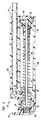
図1を参照しながら説明すると、装置10は、例えば患者から血液、血液ガスもしくは他の体液を採取するための医療装置、または典型的には静脈内に投与もしくは別な具合に投与されるタイプの流体を患者に注入するための医療装置の一部として使用することができる。図示されているように、装置10は、ハウジング12、およびカニューレホルダー16に取り付けられていて前方に突き出たカニューレ14を含んでいる(図2および図3により明確に示されている)。装置10を使用する前には、望ましくは、カニューレ14の勾配付き先端部は保護用のカバーで遮蔽されている。アクチュエータ18はハウジング12によって摺動可能に支持されており、また、ハウジング12の内部でハンドル44の反対側の端部を固定する複数の対向した可撓性のラッチを含んでいる。アクチュエータ18の前部に在るハンドル44は、以下でもっと詳しく説明されているように、装置10を通る流体の流れを停止させ、且つ、ハウジング12の内部へのカニューレ14の引込みを開始させるための、ハウジング12に対して相対的なアクチュエータ18の手動による操作を容易にする。
<Description of Preferred Embodiment>
Referring to FIG. 1, the
所望により安定化用の翼状体20を設けることができ、これは、ハウジング12から側方向に伸びており、使用者による装置10の取り扱いを容易化する。また、使用される場合、翼状体20は、装置10がテープ、縫合糸または他の同様に効果的な手段を用いて患者に固定されるときにハウジング12の回転を抑制する表面も提供する。治療学的に指示されているとおりに所望量の流体が患者に投与された後、または所望量の流体を患者から回収した後、同時的にハウジング12を把持しながらアクチュエータ18のハンドル44の前側に後方に向けられた手動による圧力を加えることにより、カニューレ14を通る流体の流れを停止させることができ、且つ、カニューレ14をハウジング12の内部に引き込むことができる。望ましい場合には、カニューレ14は、最初にカニューレを患者から引き抜いておくことなく、ハウジング12内へ引き込むことができる。装置10の使用法およびカニューレ14の引込みについては、図2および図3との関連において、以下でもっと十分に検討される。
If desired, a stabilizing
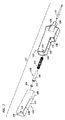
図2を参照すると、安定化用の翼状体が取り付けられていない状態で装置10が示されている。装置10のハウジング12は、下側セクション26および上側セクション28を含む2つの細長い部分を含んでいる。下側セクション26は、更に、前端32と後端34との間に配置された肩部30により定められる移行ゾーンを伴った、比較的小さな直径の前端32および比較的大きな直径の後端34を含んでいる。上側セクション28は、肩部30上のあるポイントから下側セクション26の後端34上の開放後端まで後方へ伸びており、且つ、そこに管体セグメント24を挿入することができるコネクターとして機能する長手方向のボアを含んでいる。管体セグメント24の端部は、望ましくは、何らかの適切な手段、例えば摩擦係合などにより、またはクランプ装置もしくは接着剤などを用いることにより、ハウジング12の上側セクション28の内部に保持されている。装置10の所望の使用法に応じて、管体セグメント24は、装置10をIVバッグなどの流体源または血液採取システムなどの流体容器へ接続するのに適したあらゆる所望の長さであってよい。下側セクション26は、好適には更に、後端34と移行ゾーンの肩部30との間に配置された引込み用空洞部36を含んでいる。図示されているように、引込み用空洞部36の後端34は、端部キャップ42により閉じられる開口を含んでいる。下側セクション26は、更に、移行ゾーンの肩部30の僅かに前方で頂部壁に配置されたアパーチャ38を含んでいる。穴38は上側セクション28の底に設けられた穴40と整列しており、この穴38、40の整列は、カニューレ14と管体セグメント24との間での流体流れ経路を確立するのに役立つ。
Referring to FIG. 2, the
下側セクション26の前端32における開口は摺動可能に係合されたチューブ状のアクチュエータ18によって閉じられ、前述のアクチュエータはその前縁から上向きに伸びるハンドル44を含んでいる。アクチュエータ18は、ハンドル44が下側セクション26の前端32から相隔たって位置する第1の位置からハンドル44が下側セクション26の前端32に境を接し、隣接して位置する第2の位置へ移動することができる。アクチュエータ18は、望ましくは、アクチュエータ18が前端32に接触して境を接する第2の位置へ動かされたときに、下側セクション26に設けられた穴38をカバーして閉じるのに十分な距離だけハウジング12の下側セクション26内へ長手方向に伸びるサイズに成されている。また、アクチュエータ18は、望ましくは、アクチュエータ18の後ろ側の端部から外向きに伸びる一対の直径方向反対向きのラッチを含んでいる。摺動式端部キャップ18がそれの第2の位置へ向けて動かされると、上述のラッチは下側セクション26の内壁に設けられている突出した肩部上へ摺動して、その突出した肩部と係合し、これにより、アクチュエータ18はその第2の位置にロックされ、ハウジング12から取り出すことが防止される。
The opening at the
引込み機構13はカニューレ14を支えており、カニューレホルダー16、カニューレホルダープラグ46およびスプリング22を含んでいる。下側セクション26の前部へのアクチュエータ18の取り付け後、カニューレホルダー16、スプリング22およびカニューレホルダープラグ46は、望ましくは事前に組み立てられていて、後端34に設けられている開口を通じ、更に、引込み用空洞部36を通じて下側セクション26内へ挿入される。この挿入に先立ち、望ましくは、弾力性のあるカニューレホルダープラグ46が挿入され、カニューレホルダー16の比較的大きな直径のセクション58の内部に設けられている凹部と摩擦係合する。スプリング22は、望ましくは、カニューレホルダー16のより小さな直径の前部セクション上に配置され、そこで、スプリング22は後方へ摺動し、環状肩部52と接触係合する。この組み立てられたユニットは、その後、流体の通路60が下側セクション26の頂部壁に設けられているアパーチャ38と整合するように配向され、移行ゾーンの肩部30を越えて進められる。カニューレホルダー16の前方に伸びる先端部がアクチュエータ18の前方へ突き出ているときには、スプリング22はアクチュエータ18の前部開口の内部で環状肩部に接触して着座しており、図2に示されている位置へ圧縮されている。アクチュエータ18は、その圧縮されたスプリングの力に耐え、先に説明されている如く、アクチュエータ18をハウジング12に固定する弾力性のあるラッチによって、スプリングの力の下でハウジング12から離れて前方に移動しないように成されている。このエレメント構成は、流体が中空のカニューレ14およびカニューレホルダー16を通じてカニューレホルダープラグ46内へ流入し、更に、カニューレホルダープラグ46の頂部に設けられた穴60を通り、尚も更に、引込み用空洞部のハウジング26の頂部に設けられた穴38を通り、管体アセンブリのハウジング28の底に設けられた穴40を通って管体24内へ流入するときに、カニューレ14が管体24と流体的に連通した状態になることを可能にする。同様に、流体は、反対の方向に流れ、管体24から通って、整合した穴40、38および60を通り、カニューレ14から流れ出ることもできる。後ろ側の端部キャップ42は、カニューレ14およびカニューレホルダープラグ46の取り付け後に、下側セクション26の開放端に取り付けられ、摩擦作用により下側セクション26の後ろ側の端部34の内部に保持される。
The
引込み機構13をハウジング12内へ挿入する前にカニューレ14をカニューレホルダー16に固定された関係で確保することができるが、カニューレ14は、望ましくは、カニューレホルダー16をハウジング12の内部に取り付けた後、カニューレホルダー16の突出した先端部のボア内に挿入される。図2から分かるように、カニューレホルダー16の前方に伸びた端部に設けられている開口は、カニューレ14の挿入および取り付けを容易化するため、テーパが付けられている。カニューレ14は摩擦作用によりカニューレホルダー16のボアの内部に保持することができるが、望ましくは、接着剤または当業者にとって公知の他の何らかの同様な効果を有する手段を用いて、固定された関係でカニューレホルダー16に取り付けられる。カニューレ14の勾配付き先端部の開放部分は、望ましくは、患者に挿入しやすくするために上向きになっている。図2に示されているように、中空のカニューレ14の開放後端62は、カニューレホルダー16の後端58を通じてカニューレホルダープラグ46の開放前部セクション54に伸びている。しかしながら、カニューレ14は、カニューレ14とカニューレホルダー16との間での信頼性のある係合を促進するのに十分な距離だけカニューレホルダー16内に伸びてさえいればよいことを認識すべきである。
Although the
装置10が上で説明されているようにして組み立てられるときに、圧縮されたスプリング22または他の何らかの同様な効果を有するバイアス負荷手段が、カニューレ14およびカニューレホルダー16に後方向きの付勢力を加える。カニューレホルダープラグ46により下側セクション26の比較的小さな直径の前部の内面50に対して及ぼされるこの摩擦作用による保持力は、カニューレ14を患者に挿入している間にカニューレ14およびカニューレホルダー16によりカニューレホルダープラグ46に対して後ろ向きに及ぼされる力と組み合わせた状態での、スプリング22により環状肩部52に対して及ぼされる付勢力に耐えるのに十分な大きさを有していなければならない。さもなければ、ハウジング12に対して相対的なアクチュエータ18の移動を伴うことなく、カニューレ14が早過ぎるタイミングで引っ込んでしまう可能性がある。
When the
流体の注入または抽出手順が完了し、カニューレ14の引込みを行う際には、使用者は、ハウジング12のテクスチャード加工された外面部分(図1で見ることができる)を把持するかまたは選択的に設けられる翼状体(恐らく、既に患者に取り付けられている)を押し付けるかのいずれかによってハウジング12を静止位置に維持しながらハンドル44に後方へ差し向けられた圧力を加えることにより、引込みを開始することができる。ハンドル44に加えられるこの手操作による圧力は、アクチュエータ18がハウジング12に対して相対的に後方へ移動する状態をもたらす。望ましくは、引込みは、カニューレ、典型的には針がまだ患者に挿入されている間に開始される。アクチュエータ18が後方へ動くと、アクチュエータ18の後端64とカニューレホルダー16の環状肩部52との間での接触により、カニューレホルダー16およびカニューレホルダープラグ46にも後方へ向けた力が作用する。図2から、アクチュエータ18の後端64はカニューレホルダー16の前方に面した環状肩部52の隣接部分と境を接しており、一方、スプリング22の下側に描かれている如きアクチュエータ18のその部分の後ろ側の端部は環状肩部52から僅かに離れているのを見て取ることができる。この僅かな分離は、使用者によってハンドル44に及ぼされる後方へ差し向けられた力が、その円周方向周りに均等に分配されるのではなく、環状肩部52の1つの側に対して集中される状態をもたらし、また、引込みを開始させるのに必要な手操作による力を低減させるものと確信される。
Upon completion of the fluid injection or extraction procedure and retraction of the
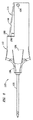
図3を参照しながら説明すると、アクチュエータ18の後方への移動に応答して、カニューレホルダープラグ46は、(肩部30を越えて)移行ゾーンを通過し、下側セクション26の比較的大きな直径の引込み用空洞部36内へ至る。カニューレホルダープラグ46が移動するときには、カニューレホルダープラグ46の外面48と下側セクション26の内壁50との間での摩擦力が低減され、また、カニューレホルダープラグ46が移行ゾーンを通り、引込み用空洞部36に入るときには、その摩擦作用による保持力は完全になくなる。この摩擦作用による保持力がアクチュエータ18のハンドル44を通じて加えられる際の使用者の指の力と圧縮されたスプリング22の付勢力との複合力により十分に低減されるポイントにおいて、スプリング22は、カニューレホルダー16およびカニューレホルダープラグ46に対して、引込み用空洞部36内に向けた後方への力を及ぼし、これにより、同時的に、カニューレホルダー16がカニューレ14の勾配付き先端部をハウジング12内へ引き入れる状態がもたらされる。当業者にとって、この開示を読めば、アクチュエータ18は、ハウジング12に対して相対的なアクチュエータの走行範囲がカニューレホルダープラグ46に確実に肩部30を越えて力を及ぼすことができるような、十分な長さでなければならないことが明らかであろう。
Referring to FIG. 3, in response to the backward movement of the actuator 18, the cannula holder plug 46 passes the transition zone (beyond the shoulder 30) and the
図3に示されているように、引込み後には、カニューレホルダープラグ46は、望ましくは、下側セクション26の後ろ側の端部キャップ42に境を接し、またはほとんど境を接した状態になる。下側セクション26は、望ましくは、カニューレ14全体が下側セクション26内に収容され、前端32からはみ出さないサイズに成されている。また、引込み後においては、アクチュエータ18の上縁がカニューレ14と下側セクション26の頂部に設けられた穴38との間の流体流れ経路を閉塞する。これにより、まだハウジング12の上側セクション28に接続されたままの管体24から流体が漏れ出ることが防止される。
As shown in FIG. 3, after retracting, the cannula holder plug 46 desirably borders or almost borders the
本発明の別の実施形態が図4および図5との関連において開示および説明される。図4を参照しながら説明すると、装置70は、採血器具またはIV注入セットの一部として使用するのが好適である。装置70は、前方に突き出ている円錐形鼻状部74を伴った前部壁72を有する実質的に矩形のハウジング;開放スロット88を伴った後部壁92;側壁98;ならびに、壁72、92および98を相互に連結する、協働性の、実質的に平坦な底部壁104および対応する頂部壁(この断面図では見えていない);を含んでいる。側壁98の反対側に在る底部壁104および対応する頂部壁(見えていない)の縁は図4では見えていないが、壁98から最も遠く隔たっているスロット88の側面を僅かに越えたポイントにおいて、前部壁72と後部壁92との間で伸びている。前部壁72の裏側に見られる摺動式トラック94は、好適には、前部壁72の一部として一体的に形成されている。
Another embodiment of the present invention is disclosed and described in connection with FIGS. Referring to FIG. 4, the
図示され、且つ、説明されているように、装置70のハウジングは、そこに引込み機構76およびアクチュエータ96を取り付けることができる構造物を定めている。引込み機構76は、好適には、更に、より大きな直径のヘッド80を有するカニューレホルダー78、およびカニューレホルダー78に対して後方に差し向けられた力を及ぼす付勢部材を含んでいる。1つの好適な付勢部材は圧縮スプリング86である。引込み機構76は、好適にはカニューレ84およびアクチュエータ96の取り付けに先立って、後ろ側から、ハウジングの前部壁72、鼻状部74および摺動式トラック94内に取り付けることができる。コイルスプリング86がカニューレホルダー78の前方に伸びる端部上に配置され、その後、カニューレホルダー78は、スプリング86の前方に面する端部がカニューレホルダー78の周囲に配置されている鼻状部74の前部開口の内部に設けられた環状肩部に接触して着座するまで、鼻状部74内に挿入される。スプリング86が圧縮されると、ヘッド80の前方に面する表面に設けられた環状肩部82の一部が、鼻状部74を通じる開口に隣接した前部壁72の後ろ向きに面する表面に接触して境を接する。引込み機構76が(鼻状部74から前方に伸びているカニューレホルダー78の一部を一次的にクランプするなどの方法により)適所に保持されている間に、アクチュエータ96は、望ましくは、壁98の反対側に位置するハウジングの側面から摺動式トラック94内に挿入され、そして、図4に示されているとおりの位置へ側方向に動かされ、そこでは、シール部材95が流体密封性のシールをもたらし、カニューレホルダー78のヘッド80からアクチュエータ96の流体流れ経路100内へ至る間での流体の流れを可能に成している。
As shown and described, the housing of the
アクチュエータ96は、好適には、ハウジング内におけるアクチュエータ96の側方向の動きを容易化するため、ハウジングの内部に設けられた少なくとも1つのガイドまたは摺動式トラック94と摺動可能に係合することができるように作られた、細長い、実質的に矩形の胴体である。アクチュエータ96の内部は、好適には、壁セクション106、108によって定められたインライン流体流れ経路100、およびアクチュエータ96が使用位置に在る間はカニューレ84からオフセットされた位置にある引込み用チャンバー102を含んでいる。好適にはエラストマーO−リングまたは別の同様に効果的なシール部材である、弾力性を有するシーリング部材95は、アクチュエータ96を通じて流体流れ経路100の前側端部に設けられた凹部に配置され、そこで、そのシール部材はカニューレホルダー78の拡大されたヘッド80の後ろ向きに面する表面と密封状態をもたらすことができる。弾力性を有するシール部材95は流体流れ経路100内へ入る方向と流体流れ経路100から出る方向のどちらの流体の漏えいをもシールすることが観察される。
アクチュエータ96が図4に示されているとおりの位置に在るときには、スプリング86は圧縮された状態に維持されており、装置70の使用後にアクチュエータ96が選択的に位置を変えられるような時まで、カニューレホルダー78に後ろ向き方向の付勢力を付与し続ける。一旦、引込み機構76およびアクチュエータ96がハウジングの内部に取り付けられると、カニューレ84の後ろ側の端部をカニューレ78の軸方向ボア内に挿入し、接着剤の使用または別の仕方で適所に固定することができる。図示されていないが、望ましくは、カニューレをカニューレホルダー78内に取り付けた後、摩擦作用により係合可能で取り外し可能な保護用のカバーがカニューレ84に設けられる。
When the
使用に先立ち、装置70は、好適には、挿入可能であるかもしくは別の仕方で通常の方法によりスロット88を通じて管体コネクター103に取り付け可能な可撓性の管体セグメント90によって流体源または流体容器に連結される。アクチュエータ96が図4に示されているような位置に在るときには、カニューレ84と管体セグメント90との間で実質的に直線状の流体流れ経路が確立される。管体コネクター103は、管体セグメント90の自由端を受け入れ、且つ、摩擦作用により係合することができるように僅かにテーパが付いたアクチュエータ96の内部のボアのあるセクションであってよく、または他の公知の手段、例えばルアーコネクター、ネジ式コネクター、クランプもしくは接着剤などによって管体セグメントの取り付けが可能なように構成することもできる。管体セグメント90は、好適には、意図的用途に適した長さおよび材料の可撓性ポリマーからなる管体である。図4に示されているようにして構成された場合、装置70は、流体を外部のソースから移し、カニューレを通じて放出するために使用することができ、または外部のソースからカニューレを通じて抽出もしくは回収し、その後、管体コネクター103とは反対側の管体セグメント90の端部から放出することもできる。
Prior to use, the
使用後、アクチュエータ96に対してカニューレ84およびカニューレホルダー78を通る長手方向軸に実質的に垂直な方向の手操作による力を加えることによって、アクチュエータ96を使用位置から引込み位置へ移動させることにより引込みが開始される。図5を参照しながら説明すると、アクチュエータ96が壁98へ向けて側方向に動かされたときには、アクチュエータ96を通じて流体流れ経路100は、もはやカニューレホルダー78のヘッド80に対向していない位置へ横側にシフトされる。同時に、ヘッド80は、圧縮されたスプリング86の付勢力による作用を受けて、カニューレホルダー78をアクチュエータ96の引込み用空洞部102内へ駆り立て、これにより、カニューレ84がハウジングの内部に回収される。この結果をもたらすためには、後壁92と鼻状部74の前側先端部との間の距離がカニューレ84の尖端を少なくとも鼻状部74内へ収容するのに十分な長さでなければならないことは明らかであろう。また、圧縮されていないスプリング86の長さは、望ましくは、引込み後、特に、装置70がカニューレを下側に向けた垂直な位置へ回転されたときに、カニューレ84の先端が装置70の前側から再び突き出ることがないような長さである。
After use, the
引込みを開始させるためにアクチュエータがハウジングに対して相対的に円弧状に位置を変えられる、本発明の別の実施形態が、図6−図10との関連において説明される。最初に図6−図8を参照すると、医療装置110が開示されており、その医療装置はハウジング112、アクチュエータ114、引込み機構118、および前方に突き出たカニューレ、好適には針122を含んでいる。ハウジング112は、更に、実質的に平坦な頂面および底面を有する中空の胴体、傾斜の付いたフィンガーパッド134、前方に伸びた開放ネック136、アクチュエータ停止レール140を含む開放型の側面および背面セクション、凹型壁セクション168、およびアクチュエータ114をハウジング112に回動可能に取り付けることができるように整列した状態で互いに対向して配置されたアパーチャ126を含んでいる。
Another embodiment of the present invention is described in the context of FIGS. 6-10, in which the actuator is repositioned in an arc relative to the housing to initiate retraction. Referring initially to FIGS. 6-8, a
アクチュエータ114は、好適には、アクチュエータ接触面132、接触面166、アクチュエータ位置決めレール138、ハウジング112のアパーチャ126との嵌め合わせ係合に挿入可能な、外向きに突き出た取り付け用ボス128、および管体用アパーチャ130を含んでいる。引込み機構118は、好適には、前方に伸びた小さな直径部分106およびその小さな直径部分106の後ろ側に配置された比較的大きな直径のヘッド108を有する針ホルダーを含んでいる。圧縮スプリング116は、小さな直径部分106上を摺動し、ヘッド108の前方に面した環状表面に接触して境を接することができるように構成されている。シール部材、好適にはO−リング120については以下で更に説明される。
The
図9を参照しながら説明すると、引込み機構が、前側の開口を通じて前方に突き出た針ホルダーの小さな直径部分106とともに、後ろ側からハウジング112のネック136内に挿入される。スプリング116は小さな直径部分106と摺動可能に係合し、スプリング116の前端がネック136の内部の前側開口に隣接した環状肩部に接触して着座する。スプリング116のもう一方の端部はヘッド108の環状肩部に接触して境を接している。スプリング116は圧縮され、アクチュエータ114によってヘッド108に対して及ぼされる対抗力により、引込み前の位置に保持される。アクチュエータ114は、取り付け用ボス128がアパーチャ126内に回動可能に挿入され、且つ、接触面166が凹型壁セクション168に隣接したハウジング112の内面に接触して境を接している状態で、ハウジングに対して相対的な使用位置に配置される。アクチュエータ114は、壁150、152を境界とする流体流れ経路154、および引込み用空洞部164を含んでいる。ハウジング112内のスペース124は、流体の流れを停止させ、且つ、引込みを開始すべくアクチュエータが位置を変えられるときに、アクチュエータ114の一部を受け入れるために設けられている。
Referring to FIG. 9, the retraction mechanism is inserted into the
アクチュエータ114がこの位置に在る場合、アクチュエータ114の中を通る流体流れ経路154は、針ホルダーの中を通る軸方向通路144及び針122の内部と流体連通する位置にある。凹部148に配備されたシール部材120は、望ましくは、壁150、152および針ホルダーのヘッド108の間での液密の密封をもたらす。このシーリング係合はヘッド108の環状肩部146により容易化される。管体コネクター156は、望ましくは、流体流れ経路154の後ろ側端部における外向きにテーパの付いた壁142を含んでおり、(仮想的な輪郭線で示されている)管体セグメント162の端部を受け入れ、且つ、その端部と係合することができるように適合化されている。引込み用空洞部164の前方に面した端部に隣接した位置に設けられたハウジング112の突き出たボス158は、アクチュエータ114が引込み前の位置から引込み位置へ不注意で動かされてしまうのを防止するために設けられている。実際には、ボス158とアクチュエータ114の接面との間の間隔は、望ましくは、例示的な目的で図9に示されている間隔よりも小さい。
When the
どちらかの方向に向けて装置110を通る流体の移送が所望の程度にまで果たされた後、アクチュエータの接触面132に対して圧力が加えられることで、アクチュエータ114が矢印160で示されている方向に回動し、アクチュエータ114がハウジング112に対する位置を変えることにより、流体の流れは容易に停止する。面160をボス158に押し付けている抵抗力に打ち勝ってヘッド108を越えてシール部材120を移動させるためには幾分かの手操作による圧力が必要になるが、その必要な力は、望ましくは、成人の使用者であれば容易に加えることができる程度の力である。繰り返しになるが、弾力性を有するシール部材120は流体流れ経路154に流入する方向と流体流れ経路154から流出する方向のどちらの流体の漏えいをもシールすることを見て取ることができよう。
After fluid transfer through the
図10を参照しながら説明すると、図示されているようにアクチュエータ114がハウジング112に対して相対的に位置を変えられた後には、針122および管体セグメント162の間での流体の流れは閉塞され、流体流れ経路154はネック136を貫く開口およびヘッド108を通る通路144からオフセットした状態になる。その上、壁150がヘッド108を通過するとすぐに、引込み用空洞部164が回動してネック136を通じる開口と同軸的に整列し、また、偶発的な針刺しを回避し、且つ、装置110の再使用を防ぐため、圧縮されたスプリング122の付勢力が針ホルダーを引込み用空洞部内へ突き出し、同時に、患者からハウジング112内へ針122の先端部を引き戻す。
Referring to FIG. 10, after the
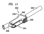
本発明の別の実施形態が図11−図16との関連において説明される。この実施形態は、その後に分析が行われることを意図した、動脈血液ガスなどのガスを含有する流体の採取において使用するのに特に好適であり、また、同じく、引込みを開始するためにハウジングに対して相対的に円弧状に位置を変えられるアクチュエータを含んでいる。最初に図11−図14を参照しながら説明すると、医療装置200が開示されており、その医療装置はハウジング226、アクチュエータ204、針ホルダー220、スプリング222、密封用シール要素218および前方に突き出た針224を含んでいる。ハウジング226は、更に、実質的に平坦な頂面および底面202を有する中空の胴体、グリップ用粗表面206を有する互いに反対側に配置され且つ一体的に形成されたフィンガーグリップ、開口228を伴って前方に伸びるテーパが付いたネック238、開放型の側面および背面、ならびにアクチュエータ204をハウジング226に回動可能に取り付けるための、整合し、且つ、互いに反対側に配置されたアパーチャ230を含んでいる。望ましくは、使用前の針224を保護するために保護カバー232が設けられており、このカバーは使用する前に針224から取り除かれなければならない。
Another embodiment of the invention is described in the context of FIGS. 11-16. This embodiment is particularly suitable for use in collecting a fluid containing a gas, such as arterial blood gas, intended for subsequent analysis and also in the housing to initiate retraction. In contrast, the actuator includes an actuator whose position is relatively changed in an arc shape. Referring initially to FIGS. 11-14, a
アクチュエータ204は、好適には、アクチュエータ接触面234、ハウジング204のアパーチャ230との嵌め合わせ係合に挿入可能な、外向きに突き出た取り付け用のボス212、引込み用空洞部216、流体流れ経路の開口周囲の凹部214、およびハウジング226から後ろ側へ伸びる管体コネクター208を含んでいる。図13および図14を参照すると、管体コネクター208は、更に、意図する用途に応じて、装置200の別の流体源または容器への取り付けを容易化するための、ルアーコネクター236の半体を含んでいる。
The
図15−図16を参照しながら説明すると、引込み機構は、針ホルダー220の小さな直径部分221が前側の開口228を通じて前方に突き出た状態で、後ろ側からハウジングのネック238を通じる軸方向通路250内に挿入することにより取り付けられる。スプリング222は小さな直径部分221と摺動可能に係合し、スプリング222の前端はネック238の前部開口228に隣接した環状肩部252に接触して着座する。スプリング222のもう一方の端部は針ホルダー220のより大きな直径のヘッド223の環状肩部に接触して境を接する。スプリング222は圧縮され、アクチュエータ204によりヘッド223に対して及ぼされる対抗力によって引込み前位置に保持される。アクチュエータ204は、取り付け用のボス212がアパーチャ230内に回動可能に挿入されている状態(図12)で、且つ、アクチュエータの接触面234が最も近い隣接したグリップ用粗表面206の下側であるハウジング226の内面に接触して境を接している状態を伴って、ハウジング226に対して相対的な使用位置に配置されている。アクチュエータ204は流体流れ経路242および引込み用空洞部216を含んでいる。ハウジング226のスペース244は、流体の流れを終了させ、且つ、引込みを開始するためにアクチュエータが位置を変えられるときに、アクチュエータ204の一部を受け入れるために設けられている。
Referring to FIGS. 15-16, the retraction mechanism includes an
アクチュエータ204が図15に示されている位置に在る場合、アクチュエータ204を通じて流体流れ経路242は針ホルダーを通る軸方向通路225および針224の内部の軸方向通路258と流体的に連通した状態で配置されている。凹部214に着座した密封用シール部材246は、望ましくは、流体流れ経路242の前端と針ホルダーのヘッド223との間で流体密封性の密封状態が得られる。管体コネクター208は、望ましくは、流体流れ経路242との流体連通状態をもたらす階段状のボア240を含んでいる。引込み用空洞部216の前方に面した端部に隣接して配置されているハウジング226の突き出たボス235は、アクチュエータが不注意で引込み前位置から図16に示されている引込み位置へ動かされるのを防止するために設けられている。
When the
図16を参照しながら説明すると、どちらかの方向における装置200を通る流体の移送が所望の程度にまで果たされた後、その流体の流れは、アクチュエータの接触面234に対して圧力を加え、これにより、アクチュエータが矢印260で示されている方向に回動する状態をもたらすことによって、ハウジング226に対して相対的にアクチュエータの位置を変えることにより容易に終了される。面237(図15)をボス235に押し付けている抵抗力に打ち勝ってヘッド223を越えてシール部材246を移動させるためには幾分かの手操作による圧力が必要になるが、その必要な力は、望ましくは、成人の使用者であれば易々と加えることができる範囲内の力である。アクチュエータが図16に示されているようにハウジング112に対して相対的に位置を変えられた後には、針244および管体コネクター208の間での流体の流れは閉塞され、流体流れ経路242は通路248、250を通る開口からオフセットされた状態になる。その上、引込み用空洞部164が回動されて通路248、250と同軸的に整列した状態になるとすぐに、偶発的な針刺しを回避し、且つ、再使用を防ぐため、圧縮されたスプリング224の付勢力が針ホルダー221、223を引込み用空洞部内へ突き出し、同時に、針224の先端部を患者からハウジング226内へ引き戻す。
Referring to FIG. 16, after fluid transfer through the
本発明の別の実施形態が図17−図20との関連において説明される。流体の抽出、採取または注入において使用するのに特に好適なこの実施形態もアクチュエータを含んでおり、そのアクチュエータは、引込みを開始するためにハウジングに対して相対的に回転的に位置を変えられ、最も好適には円弧状に位置を変えられる。最初に図17−図18を参照しながら説明すると、医療装置300が開示されており、その医療装置はハウジング304、アクチュエータ316、針ホルダー312、スプリング310、密封要素314および前方に突き出た針308を含んでいる。ハウジング304は、更に、実質的に平坦な頂面および底面を有する中空の胴体、グリップ用粗表面340を伴って互いに反対側に配置され且つ一体的に形成されたフィンガーグリップ、前方に伸びる開口を伴って前方に伸びるテーパが付いたネック306、開放型の側面および背面、ならびにアクチュエータ316をハウジング304に回動可能に取り付けるための、整合し、且つ、互いに反対側に配置されたアパーチャ324を含んでいる。望ましくは、使用前の針308を保護するために保護カバー302が設けられており、このカバーは使用する前に針308から取り除かれなければならない。
Another embodiment of the invention is described in the context of FIGS. 17-20. This embodiment, particularly suitable for use in fluid extraction, collection or infusion, also includes an actuator that is rotationally repositioned relative to the housing to initiate retraction, Most preferably, the position can be changed in an arc shape. Referring initially to FIGS. 17-18, a
図18および図19を参照すると、本発明のこの実施形態においては、別の装置(図示せず)を取り付けるのに適した長さを有する管体セグメント318によってアクチュエータ316を通じて流体流れ経路328へ取り付けることが可能な外部コネクター胴体322が設けられており、ここで、前述の別の装置は、患者に注入すべき流体、または患者から抽出すべき流体のためのソースであるか、またはそのような流体用の容器であってよい。図19を参照しながら説明すると、管体セグメント318(長さの範囲が例えば1フィートから4フィートもしくはそれ以上であってよい)が、好適には、アクチュエータ316の後ろ側に挿入され、接着剤による接着、溶接、クランプ、または別な仕方で適所に固定されて流体流れ経路328との流体連通状態を確立することができ、また、同様に、鼻状部320に設けられている開口を通じてコネクターの胴体322にも取り付けることができ、これにより、そのコネクター胴体322を通って階段状の軸方向ボア332との流体的連通状態を確立することができる。コネクター胴体322の後ろ側に設けられたコネクター334は、望ましくは、別の装置、好適には流体源または容器への取り付けを容易化するために設けられており、最も好適には、標準的なルアーコネクターの半分が設けられている。また、コネクター胴体322の鼻状部320に挿入された管体セグメントの端部も、好適には、接着剤を用いて、または何らかの他の適切な通常の手段により取り付けられる。更に、コネクター胴体322は、必要に応じてコネクター胴体322を別の表面または物品に固定する際に使用するための、互いに反対側に向けられた安定化用の翼状体336を随意選択的に備えることもできる。
Referring to FIGS. 18 and 19, in this embodiment of the invention, a
ハウジング304の内部にアクチュエータ316を取り付ける前に、針ホルダー312およびスプリング310を含む引込み機構が、好適には、針ホルダー312のより小さな直径部分がネック306の前部の開口を通じて前方に突き出た状態で、図11−図17の実施形態との関連において先に説明されているように、後ろ側からハウジング304のネック306内に挿入することにより取り付けられる。スプリング310は取り付け中に圧縮され、アクチュエータ316により針ホルダー312のヘッドに対して及ぼされる対抗力によってその引込み前位置に保持される。図19では、アクチュエータ316は、図15のハウジング226との関連においてアクチュエータ204に対して先に説明されているように、ハウジング304の内部のアクチュエータの使用位置に配置されている。アクチュエータ316は流体流れ経路328および引込み用空洞部330を含んでいる。ハウジング304のスペース326は、流体の流れを終了させ、且つ、引込みを開始するためにアクチュエータが位置を変えられるときに、アクチュエータ316の一部を受け入れるために設けられている。
Prior to mounting the
アクチュエータ316が図19に示されている位置に在る場合、アクチュエータ316を通じて流体流れ経路328は針ホルダー312を通る軸方向通路および針308の内部の軸方向通路258と流体連通した状態で配置されている。シール用エラストマー部材314は、望ましくは、流体流れ経路328の前端と針ホルダー312のヘッドとの間での流体密封性のシーリング係合をもたらす。流体流れ経路328の後ろ側の部分は、望ましくは、先に説明されているように、管体セグメント318の端部を受け入れ、且つ、その端部と係合するためのテーパ付きの壁を含んでいる。図15のハウジング226のボス235との関連において先に説明されている如くにして突き出たボスは、望ましくは、アクチュエータ316が不注意で図19の引込み前位置から図20に示されている引込み位置へ動かされるのを防止するため、引込み用空洞部330の前方に面した端部に隣接して配置されている。
When the
図20を参照しながら説明すると、どちらかの方向における装置300を通る流体の移送が所望の程度にまで果たされた後、その流体の流れは、矢印338で指示されているようにアクチュエータの接触面に対して圧力を加え、これにより、アクチュエータ316が矢印338で示されている方向に回動する状態をもたらすことによって、ハウジング304に対して相対的にアクチュエータ316の位置を変えることにより容易に終了される。アクチュエータが図20に示されているようにハウジング304に対して相対的に位置を変えられた後には、針308および管体コネクターの胴体322の間での流体の流れは閉塞され、そして、流体流れ経路328は鼻状部306を通る開口からからオフセットされた状態になる。その上、引込み用空洞部330が回動されてハウジング304のネック306を通る開口と同軸的に整列した状態になるとすぐに、偶発的な針刺しを回避し、且つ、再使用を防ぎ、これにより、流体感染性の病原菌が別の人に広がることに関する潜在的可能性を低減させるため、圧縮されたスプリング308の付勢力が針ホルダー312を引込み用空洞部330内へ押しやり、同時に、針308の先端部を患者からハウジング304内へ引き戻す。
Referring to FIG. 20, after the fluid transfer through the
本明細書で開示されている場合、すべてのハウジング、アクチュエータ、カニューレホルダー、保護カバー、端部キャップおよび管体コネクターは、例えばプラスチック、金属、セラミックまたはガラスなどのあらゆる適切な材料でできていてよい。IV注入および血液採取などの医療用途の場合、成形ポリプロピレンの使用が好適である。同様に、意図する使用または用途に応じて、本発明において使用するのに適したカニューレは、金属、プラスチックまたはセラミック材料でできていてよく、但し、金属であることが好適である。流体シール部材またはカニューレホルダープラグなどとして使用される弾性パーツは、望ましくは、ゴム、他のエラストマーポリマーまたはゴム変性プラスチックでできている。 As disclosed herein, all housings, actuators, cannula holders, protective covers, end caps and tube connectors may be made of any suitable material such as, for example, plastic, metal, ceramic or glass. . For medical applications such as IV infusion and blood collection, the use of molded polypropylene is preferred. Similarly, depending on the intended use or application, a cannula suitable for use in the present invention may be made of a metal, plastic or ceramic material, although preferably it is a metal. The elastic parts used as fluid seal members or cannula holder plugs are preferably made of rubber, other elastomeric polymers or rubber modified plastics.
図1−図5との関連において開示されている装置を使用し、且つ、引込み中、ハウジングが静止位置に維持されることを前提としている場合には、本装置の後ろ側に連結されている管体セグメントは、流体の流れを終了させ、且つ、カニューレをハウジング内に引っ込めるためにアクチュエータが位置を変えられるときに、軸方向に、側方向にまたは方向的に動かされない。ハウジングに対して相対的に回動する際のアクチュエータの円弧状の位置変動により流れが終了され、且つ、カニューレが引き込まれる、図6−図20の装置を使用する場合、取り付けられた管体セグメントの軸方向、側方向および方向的な移動は、従来の装置を使用した場合のこれまでの走行距離に比べて僅かである。 If the device disclosed in connection with FIGS. 1-5 is used and if it is assumed that the housing is maintained in a rest position during retraction, it is connected to the rear side of the device. The tube segment is not moved axially, laterally or directional when the actuator is repositioned to terminate fluid flow and retract the cannula into the housing. Attached tube segment when using the device of FIGS. 6-20, where flow is terminated by the arcuate position variation of the actuator as it rotates relative to the housing and the cannula is retracted The axial direction, lateral direction, and directional movement are slightly less than the distance traveled so far when a conventional apparatus is used.
本開示を読めば、当業者にとって、本発明の他の変形態様および変更態様が同様に明らかになるものと考えられ、ここで開示されている本発明の範囲は、本発明者らが合法的に権利を与えられる添付の特許請求の範囲の最も広い解釈によってのみ制限されることが意図されている。 Upon reading this disclosure, other variations and modifications of this invention will become apparent to those skilled in the art as well, and the scope of the invention disclosed herein is statutory by the inventors. It is intended that the invention be limited only by the broadest interpretation of the appended claims.
Claims (87)
ハウジングから突出するカニューレと、
外部にある流体源または流体容器に取付け可能なコネクターと、
カニューレ及びコネクターの間で流体の流れを可能にする流体流れ経路と、
少なくとも一部分が移動可能なアクチュエータであって、流体流れ経路の一部分の位置を変えることで、流体の流れを終了させるか又は流れ方向を変えられるようになし、カニューレの引込みを開始させることができるアクチュエータとを具えている、装置。 A housing;
A cannula protruding from the housing;
A connector attachable to an external fluid source or fluid container;
A fluid flow path that allows fluid flow between the cannula and the connector;
Actuator that is movable at least in part, and can change the position of a part of the fluid flow path to terminate fluid flow or change the direction of flow and initiate cannula retraction With the device.
ハウジングから突出するカニューレと、
カニューレをハウジングの中に移動させることができるように構成される引込み機構と、
引込み機構の後方に配備され、外部にある流体源または流体容器に取付け可能なコネクターと、
カニューレ及びコネクターの間で流体の流れを可能にする流体流れ経路と、
ハウジングに関して第1位置及び第2位置の間で選択的に移動可能な部分を少なくとも有するアクチュエータであって、第1位置にあるとき、流体流れ経路を通じて流体の流れを可能にし、第2位置にあるとき、流体の流れを停止させるか又は流れ方向を変えることができるアクチュエータとを具えており、
アクチュエータが第1位置から第2位置に移動することにより、カニューレの引込みが開始される、装置。 A housing;
A cannula protruding from the housing;
A retracting mechanism configured to allow movement of the cannula into the housing;
A connector disposed behind the retraction mechanism and attachable to an external fluid source or fluid container;
A fluid flow path that allows fluid flow between the cannula and the connector;
An actuator having at least a portion selectively movable between a first position and a second position with respect to the housing, wherein when in the first position, allows fluid flow through the fluid flow path and is in the second position And an actuator that can stop the flow of fluid or change the flow direction,
The apparatus wherein the retracting of the cannula is initiated by the movement of the actuator from the first position to the second position.
ハウジングから突出するカニューレと、
カニューレに対向して配備され、流体源または流体容器に接続可能なコネクターと、
カニューレ及びコネクターの間で流体の流れを可能にする流体流れ経路と、
ハウジングに支持されたカニューレ引込み機構と、
ハウジングに支持され、少なくとも一部分がハウジングに関して第1位置及び第2位置の間で選択的に移動可能なアクチュエータであって、第1位置にあるとき、流体流れ経路を通る流体の流れを可能にし、第2位置にあるとき、流体の流れを停止させるか又は流れ方向を変えることができるアクチュエータとを具えており、
アクチュエータが第1位置から第2位置に移動することにより、カニューレの引込みが開始される、装置。 A housing;
A cannula protruding from the housing;
A connector deployed opposite the cannula and connectable to a fluid source or fluid container;
A fluid flow path that allows fluid flow between the cannula and the connector;
A cannula retraction mechanism supported by the housing;
An actuator supported on the housing and at least partially movable relative to the housing between a first position and a second position to allow fluid flow through the fluid flow path when in the first position; An actuator capable of stopping fluid flow or changing flow direction when in the second position;
The apparatus wherein the retracting of the cannula is initiated by the movement of the actuator from the first position to the second position.
ハウジングと、
ハウジングから突出する先端部を有するカニューレと、
カニューレを支持するカニューレホルダーと、
流体源または流体容器に取付け可能なコネクターと、
常時開放され、カニューレ及びコネクターの間で流体の流れを可能にする流体流れ経路と、
ハウジングに支持され、ハウジングに関して第1位置及び第2位置の間で移動可能なアクチュエータと、
カニューレホルダーを、カニューレの先端部がハウジングから突出しない位置へ付勢する引込み部材とを具え、
アクチュエータが第1位置から第2位置に移動し、常時開放されている流体流れ経路の少なくとも一部の位置を変えることにより、流体流れ経路を通る流体の流れが終了されるようにした、医療用装置。 A medical device useful for infusion therapy or fluid extraction,
A housing;
A cannula having a tip protruding from the housing;
A cannula holder for supporting the cannula;
A connector attachable to a fluid source or fluid container;
A fluid flow path that is always open and allows fluid flow between the cannula and the connector;
An actuator supported by the housing and movable between a first position and a second position with respect to the housing;
A retractable member for biasing the cannula holder to a position where the tip of the cannula does not protrude from the housing;
The actuator is moved from the first position to the second position, and the flow of the fluid through the fluid flow path is terminated by changing the position of at least a part of the fluid flow path that is always open. apparatus.
ハウジングから突出するカニューレと、
外部にある流体源または流体容器に取付け可能なコネクターと、
カニューレ及び流体源又は流体容器の間で流体の流れを可能にする流体流れ経路と、
少なくとも一部分がハウジングに関して移動可能なアクチュエータであって、流体流れ経路の一部分の位置を変位することで、流体の流れを終了させるか又は流れ方向を変えられるようになし、カニューレの引込みを開始させることができるアクチュエータとを具えている、医療用装置。 A housing;
A cannula protruding from the housing;
A connector attachable to an external fluid source or fluid container;
A fluid flow path that allows fluid flow between the cannula and a fluid source or fluid container;
An actuator that is movable at least in part with respect to the housing, and displacing a position of a portion of the fluid flow path so that the fluid flow is terminated or the flow direction can be changed and the cannula retraction is initiated A medical device comprising an actuator capable of
Applications Claiming Priority (3)
| Application Number | Priority Date | Filing Date | Title |
|---|---|---|---|
| US12/136,462 US20090306601A1 (en) | 2008-06-10 | 2008-06-10 | Fluid Flow Control Device with Retractable Cannula |
| US12/136,462 | 2008-06-10 | ||
| PCT/US2009/037742 WO2009151704A1 (en) | 2008-06-10 | 2009-03-20 | Fluid flow control device with retractable cannula |
Publications (3)
| Publication Number | Publication Date |
|---|---|
| JP2011522671A true JP2011522671A (en) | 2011-08-04 |
| JP2011522671A5 JP2011522671A5 (en) | 2012-05-17 |
| JP5508404B2 JP5508404B2 (en) | 2014-05-28 |
Family
ID=41400967
Family Applications (1)
| Application Number | Title | Priority Date | Filing Date |
|---|---|---|---|
| JP2011513511A Active JP5508404B2 (en) | 2008-06-10 | 2009-03-20 | Fluid flow control device with retractable cannula |
Country Status (21)
| Country | Link |
|---|---|
| US (4) | US20090306601A1 (en) |
| EP (1) | EP2285437B1 (en) |
| JP (1) | JP5508404B2 (en) |
| KR (1) | KR101618039B1 (en) |
| CN (1) | CN101601877B (en) |
| AR (1) | AR072100A1 (en) |
| AU (1) | AU2009258050B2 (en) |
| BR (1) | BRPI0913442B8 (en) |
| CA (1) | CA2724197C (en) |
| CO (1) | CO6280505A2 (en) |
| EG (1) | EG27045A (en) |
| ES (1) | ES2663531T3 (en) |
| MA (1) | MA32403B1 (en) |
| MX (1) | MX2010013589A (en) |
| PE (1) | PE20100474A1 (en) |
| RU (1) | RU2500436C2 (en) |
| SA (1) | SA109300245B1 (en) |
| TW (1) | TWI401099B (en) |
| UA (1) | UA101667C2 (en) |
| WO (1) | WO2009151704A1 (en) |
| ZA (1) | ZA201008099B (en) |
Cited By (6)
| Publication number | Priority date | Publication date | Assignee | Title |
|---|---|---|---|---|
| JP2016503675A (en) * | 2012-12-14 | 2016-02-08 | リトラクタブル テクノロジーズ, インコーポレイテッドRetractable Technologies, Inc. | Needle retractor |
| JP2016510626A (en) * | 2013-03-15 | 2016-04-11 | リトラクタブル テクノロジーズ,インコーポレイテッドRetractable Technologies,Inc. | Needle retractor |
| JP2016510627A (en) * | 2013-03-15 | 2016-04-11 | リトラクタブル テクノロジーズ, インコーポレイテッドRetractable Technologies, Inc. | Front attachment device for thumb-operated retractable syringe |
| JP2016529077A (en) * | 2013-09-06 | 2016-09-23 | リトラクタブル テクノロジーズ, インコーポレイテッドRetractable Technologies, Inc. | Medical device with sliding front attachment and retractable needle |
| JP2016529078A (en) * | 2013-09-06 | 2016-09-23 | リトラクタブル テクノロジーズ, インコーポレイテッドRetractable Technologies, Inc. | A medical device that combines a sliding front attachment and a retractable needle |
| JP2016537182A (en) * | 2012-12-14 | 2016-12-01 | リトラクタブル テクノロジーズ, インコーポレイテッドRetractable Technologies, Inc. | Front attachment device for a syringe with a rotationally retractable needle |
Families Citing this family (49)
| Publication number | Priority date | Publication date | Assignee | Title |
|---|---|---|---|---|
| ES2533878T3 (en) | 2004-09-03 | 2015-04-15 | L.O.M. Laboratories Inc. | Gas-operated retractable syringe |
| US8197420B2 (en) | 2006-12-18 | 2012-06-12 | Magnolia Medical Technologies, Inc. | Systems and methods for parenterally procuring bodily-fluid samples with reduced contamination |
| US20090306601A1 (en) | 2008-06-10 | 2009-12-10 | Shaw Thomas J | Fluid Flow Control Device with Retractable Cannula |
| US8496600B2 (en) | 2008-06-10 | 2013-07-30 | Retractable Technologies, Inc. | Non-reusable collection device for bodily fluids |
| US9814841B2 (en) * | 2008-06-10 | 2017-11-14 | Retractable Technologies, Inc. | Medical device with sliding frontal attachment and retractable needle |
| BR112012016884A2 (en) * | 2010-01-07 | 2018-06-05 | Retractable Technologies, Inc | retractable needle blood draw device |
| WO2011111046A1 (en) * | 2010-03-10 | 2011-09-15 | White Innovation Ltd. | Injector |
| US8864684B2 (en) | 2011-10-13 | 2014-10-21 | Magnolia Medical Technologies, Inc. | Fluid diversion mechanism for bodily-fluid sampling |
| GB2497305B (en) | 2011-12-06 | 2014-01-01 | Major Ltd C | A sharps retraction device |
| CN102670213A (en) * | 2012-03-27 | 2012-09-19 | 河南曙光健士医疗器械集团有限公司 | Disposable anti-pricking venous blood sampling needle |
| US9022950B2 (en) | 2012-05-30 | 2015-05-05 | Magnolia Medical Technologies, Inc. | Fluid diversion mechanism for bodily-fluid sampling |
| US9060724B2 (en) | 2012-05-30 | 2015-06-23 | Magnolia Medical Technologies, Inc. | Fluid diversion mechanism for bodily-fluid sampling |
| WO2014022275A1 (en) | 2012-08-01 | 2014-02-06 | Magnolia Medical Technologies, Inc. | Fluid diversion mechanism for bodily-fluid sampling |
| EP3318295B1 (en) | 2012-10-11 | 2021-04-14 | Magnolia Medical Technologies, Inc. | System for delivering a fluid to a patient with reduced contamination |
| CA2931983C (en) | 2012-11-30 | 2021-12-07 | Magnolia Medical Technologies, Inc. | Syringe based fluid diversion mechanism for bodily-fluid sampling |
| US10772548B2 (en) | 2012-12-04 | 2020-09-15 | Magnolia Medical Technologies, Inc. | Sterile bodily-fluid collection device and methods |
| CN107874786B (en) | 2012-12-04 | 2020-11-24 | 木兰医药技术股份有限公司 | Device for taking a sample of body fluid from a patient |
| USD829891S1 (en) | 2012-12-14 | 2018-10-02 | Retractable Technologies, Inc. | Syringe with offset needle retraction chamber and frontal attachment |
| TWI668029B (en) * | 2012-12-14 | 2019-08-11 | 美商伸縮科技股份有限公司 | Medical device with sliding frontal attachment and retractable needle |
| US9320469B2 (en) | 2012-12-14 | 2016-04-26 | Retractable Technologies, Inc. | Retractable needle for blood gas sampling |
| US10568554B2 (en) | 2012-12-14 | 2020-02-25 | Retractable Technologies, Inc. | Blood collection tube holder with slide-activated needle retraction |
| USD823457S1 (en) | 2012-12-14 | 2018-07-17 | Retractable Technologies, Inc. | Blood collection tube holder with offset needle retraction chamber and frontal attachment |
| USD823461S1 (en) | 2012-12-14 | 2018-07-17 | Retractable Technologies, Inc. | Slimline syringe with offset needle retraction chamber and frontal attachment |
| USD823463S1 (en) | 2012-12-14 | 2018-07-17 | Retractable Technologies, Inc. | Frontal attachment for medical device |
| TWI576130B (en) * | 2012-12-14 | 2017-04-01 | 湯瑪士 索 | Retractable needle device |
| JP6437515B2 (en) | 2013-03-12 | 2018-12-12 | マグノリア メディカル テクノロジーズ,インコーポレイテッド | Method and apparatus for selectively occluding a lumen of a needle |
| US9456775B2 (en) | 2013-09-06 | 2016-10-04 | Millaghi Medical, Inc. | Passive safety I.V. blood collection catheter |
| AU2013406223B2 (en) * | 2013-11-26 | 2020-03-05 | Retractable Technologies, Inc. | Frontal attachment device for syringe with rotationally activated retractable needle |
| USD780914S1 (en) * | 2014-09-05 | 2017-03-07 | Tidi Products, Llc | Catheter adhesive device |
| AU2015337782B2 (en) | 2014-10-31 | 2020-02-13 | L.O.M. Laboratories Inc. | Retractable needle syringe |
| US10709847B2 (en) | 2015-01-20 | 2020-07-14 | L.O.M. Laboratories Inc. | Retractable needle syringe with unitary propellant release module |
| DE102015205517A1 (en) * | 2015-03-26 | 2016-09-29 | B. Braun Melsungen Ag | Medical fluid control device for a medical fluid line system |
| EP3769681B1 (en) | 2015-06-12 | 2022-03-02 | Magnolia Medical Technologies, Inc. | Bodily-fluid sampling and transfer device |
| US11504517B2 (en) | 2015-12-11 | 2022-11-22 | Nxstage Medical, Inc. | Fluid line connector devices methods and systems |
| CA3029592C (en) | 2016-07-05 | 2023-05-23 | Retractable Technologies, Inc. | Blood collection tube holder with slide-activated needle retraction |
| US11000217B2 (en) * | 2016-07-05 | 2021-05-11 | Retractable Technologies, Inc. | Blood collection tube holder with discharge needle displacement member |
| USD828653S1 (en) | 2016-12-14 | 2018-09-11 | Brandon Penland | Treatment applicator |
| CN111212597B (en) | 2017-09-12 | 2023-04-11 | 木兰医药技术股份有限公司 | Fluid control device and method of use |
| US10646148B2 (en) * | 2017-09-22 | 2020-05-12 | Retractable Technologies, Inc. | Bodily fluid collection device with integral tube seal |
| CA3087992A1 (en) | 2017-12-07 | 2019-06-13 | Magnolia Medical Technologies, Inc. | Fluid control devices and methods of using the same |
| FR3077737B1 (en) * | 2018-02-12 | 2023-06-16 | Adda Jean Marc | HEAD FOR INJECTION OF A FLUID SUBSTANCE ALLOWING CONTROL OF THE INJECTION SITE BEFORE INJECTION OF THE FLUID SUBSTANCE AND SYRINGE COMPRISING SUCH A HEAD |
| US20190282147A1 (en) * | 2018-03-16 | 2019-09-19 | Thomas J. Shaw | Blood Collection Tube Holder with Single Needle |
| US11141570B2 (en) * | 2018-03-29 | 2021-10-12 | Retractable Technologies, Inc. | IV catheter with retractable needle and laterally offset biasing element and needle retraction cavity |
| IT201900001685A1 (en) * | 2019-02-06 | 2020-08-06 | Sol Millennium Swiss R&D Center Sa | MEDICAL DEVICE WITH OFFSET CANNULA |
| AU2020218544A1 (en) | 2019-02-08 | 2021-09-16 | Magnolia Medical Technologies, Inc. | Devices and methods for bodily fluid collection and distribution |
| JP2022523951A (en) | 2019-03-11 | 2022-04-27 | マグノリア メディカル テクノロジーズ,インコーポレイテッド | Fluid control device and how to use it |
| US11529080B2 (en) | 2019-04-22 | 2022-12-20 | The Monarch Company Llc | Blood collection assembly |
| CN113080956B (en) * | 2021-04-09 | 2023-05-02 | 自贡市第一人民医院 | Blood sampling indwelling needle |
| CN116983494B (en) * | 2023-09-27 | 2023-11-28 | 四川大学华西医院 | Detection device for post-operative cardiac drainage tube |
Citations (5)
| Publication number | Priority date | Publication date | Assignee | Title |
|---|---|---|---|---|
| US5685863A (en) * | 1995-08-15 | 1997-11-11 | Mdc Investment Holdings Inc. | Retractable needle apparatus for transmission of intravenous fluids |
| JP2003180829A (en) * | 2001-10-24 | 2003-07-02 | Becton Dickinson & Co | Retractable needle assembly |
| US20060155244A1 (en) * | 2002-05-27 | 2006-07-13 | Sergey Popov | Safety catheter device |
| WO2007132732A1 (en) * | 2006-05-17 | 2007-11-22 | Terumo Kabushiki Kaisha | Indwelling needle assembly |
| JP2008073238A (en) * | 2006-09-21 | 2008-04-03 | Nipro Corp | Indwelling needle |
Family Cites Families (26)
| Publication number | Priority date | Publication date | Assignee | Title |
|---|---|---|---|---|
| US4624393A (en) | 1981-07-02 | 1986-11-25 | Survival Technology, Inc. | Split hub assembly for a necked down cartridge tube |
| CH673775A5 (en) * | 1987-07-10 | 1990-04-12 | Jacques Verlier | |
| US4813426A (en) * | 1987-11-09 | 1989-03-21 | Habley Medical Technology Corporation | Shielded safety syringe having a retractable needle |
| IT1242868B (en) | 1990-10-05 | 1994-05-18 | Amorino Morandini | AUTOMATIC CONCEALED NEEDLE DEVICE APPLICABLE ON SYRINGES FOR INJECTIONS OR SIMILAR |
| US5423758A (en) * | 1993-12-16 | 1995-06-13 | Shaw; Thomas J. | Retractable fluid collection device |
| CA2168615A1 (en) * | 1995-03-07 | 1996-09-08 | Timothy J. Erskine | Catheter-advancement actuated needle retraction system |
| US6277102B1 (en) * | 1995-05-17 | 2001-08-21 | Brian D. Carilli | Hypodermic syringe system and method of manufacture |
| GB9617502D0 (en) | 1996-08-21 | 1996-10-02 | Boc Group Plc | Medical devices |
| JP3967408B2 (en) * | 1996-12-20 | 2007-08-29 | メディキット株式会社 | Syringe safety needle |
| US5779679A (en) * | 1997-04-18 | 1998-07-14 | Shaw; Thomas J. | Winged IV set with retractable needle |
| TW325410B (en) * | 1997-07-18 | 1998-01-21 | Wenn-Neng Liou | Winglike retractive clysis equipment useful for the operators' safety when they process the cylsis operation for the patients |
| US6039713A (en) * | 1997-08-28 | 2000-03-21 | Mdc Investment Holdings, Inc. | Pre-filled retractable needle injection device |
| JP4035684B2 (en) * | 1997-11-12 | 2008-01-23 | エム ディー シー インベストメント ホールディングス インコーポレイテッド | Medical device with retractable needle |
| US6063040A (en) * | 1998-01-16 | 2000-05-16 | Specialized Health Products, Inc. | Self retracting needle apparatus and method for phlebotomy |
| US6210371B1 (en) * | 1999-03-30 | 2001-04-03 | Retractable Technologies, Inc. | Winged I.V. set |
| FR2809627B1 (en) | 2000-06-05 | 2003-01-17 | Altair | SINGLE USE SYRINGE INCLUDING A RETRACTABLE NEEDLE |
| US20020068907A1 (en) * | 2000-09-05 | 2002-06-06 | Dysarz Edward D. | Safety syringe with retraction trunk |
| US20020165501A1 (en) * | 2001-05-04 | 2002-11-07 | Yang Zhan Bo | Safety Syringe |
| US6494863B1 (en) * | 2001-10-15 | 2002-12-17 | Retractable Technologies, Inc. | One-use retracting syringe with positive needle retention |
| US7294118B2 (en) * | 2001-10-24 | 2007-11-13 | Becton, Dickinson And Company | Retractable needle assembly |
| AU2003201336A1 (en) * | 2002-03-19 | 2003-10-16 | Becton, Dickinson And Company | Needle assembly |
| AT413648B (en) * | 2002-10-02 | 2006-04-15 | Greiner Bio One Gmbh | RECORDING DEVICE WITH ADJUSTABLE COVERING ELEMENT |
| ES2424947T3 (en) * | 2003-03-20 | 2013-10-10 | Unitract Syringe Pty Ltd | Syringe Spring Retention Medium |
| US6808512B1 (en) * | 2003-04-09 | 2004-10-26 | Hsiu-Chih Lin | Safety syringe |
| WO2006123645A1 (en) * | 2005-05-19 | 2006-11-23 | Nipro Corporation | Wing-like needle assembly |
| US20090306601A1 (en) | 2008-06-10 | 2009-12-10 | Shaw Thomas J | Fluid Flow Control Device with Retractable Cannula |
-
2008
- 2008-06-10 US US12/136,462 patent/US20090306601A1/en not_active Abandoned
-
2009
- 2009-03-20 KR KR1020117000202A patent/KR101618039B1/en active IP Right Grant
- 2009-03-20 JP JP2011513511A patent/JP5508404B2/en active Active
- 2009-03-20 WO PCT/US2009/037742 patent/WO2009151704A1/en active Application Filing
- 2009-03-20 CA CA2724197A patent/CA2724197C/en active Active
- 2009-03-20 BR BRPI0913442A patent/BRPI0913442B8/en active IP Right Grant
- 2009-03-20 RU RU2010154095/14A patent/RU2500436C2/en active
- 2009-03-20 MX MX2010013589A patent/MX2010013589A/en active IP Right Grant
- 2009-03-20 EP EP09762998.4A patent/EP2285437B1/en active Active
- 2009-03-20 AU AU2009258050A patent/AU2009258050B2/en active Active
- 2009-03-20 UA UAA201100228A patent/UA101667C2/en unknown
- 2009-03-20 ES ES09762998.4T patent/ES2663531T3/en active Active
- 2009-03-26 TW TW098109908A patent/TWI401099B/en active
- 2009-04-15 PE PE2009000518A patent/PE20100474A1/en not_active Application Discontinuation
- 2009-04-26 SA SA109300245A patent/SA109300245B1/en unknown
- 2009-06-09 CN CN200910146152.1A patent/CN101601877B/en active Active
- 2009-06-10 AR ARP090102104A patent/AR072100A1/en unknown
-
2010
- 2010-11-11 ZA ZA2010/08099A patent/ZA201008099B/en unknown
- 2010-11-24 CO CO10147616A patent/CO6280505A2/en not_active Application Discontinuation
- 2010-12-09 EG EG2010122092A patent/EG27045A/en active
- 2010-12-20 MA MA33441A patent/MA32403B1/en unknown
-
2012
- 2012-05-14 US US13/470,855 patent/US8469927B2/en active Active
-
2013
- 2013-05-24 US US13/902,564 patent/US9440033B2/en active Active
-
2016
- 2016-07-25 US US15/218,949 patent/US9694139B2/en active Active
Patent Citations (5)
| Publication number | Priority date | Publication date | Assignee | Title |
|---|---|---|---|---|
| US5685863A (en) * | 1995-08-15 | 1997-11-11 | Mdc Investment Holdings Inc. | Retractable needle apparatus for transmission of intravenous fluids |
| JP2003180829A (en) * | 2001-10-24 | 2003-07-02 | Becton Dickinson & Co | Retractable needle assembly |
| US20060155244A1 (en) * | 2002-05-27 | 2006-07-13 | Sergey Popov | Safety catheter device |
| WO2007132732A1 (en) * | 2006-05-17 | 2007-11-22 | Terumo Kabushiki Kaisha | Indwelling needle assembly |
| JP2008073238A (en) * | 2006-09-21 | 2008-04-03 | Nipro Corp | Indwelling needle |
Cited By (6)
| Publication number | Priority date | Publication date | Assignee | Title |
|---|---|---|---|---|
| JP2016503675A (en) * | 2012-12-14 | 2016-02-08 | リトラクタブル テクノロジーズ, インコーポレイテッドRetractable Technologies, Inc. | Needle retractor |
| JP2016537182A (en) * | 2012-12-14 | 2016-12-01 | リトラクタブル テクノロジーズ, インコーポレイテッドRetractable Technologies, Inc. | Front attachment device for a syringe with a rotationally retractable needle |
| JP2016510626A (en) * | 2013-03-15 | 2016-04-11 | リトラクタブル テクノロジーズ,インコーポレイテッドRetractable Technologies,Inc. | Needle retractor |
| JP2016510627A (en) * | 2013-03-15 | 2016-04-11 | リトラクタブル テクノロジーズ, インコーポレイテッドRetractable Technologies, Inc. | Front attachment device for thumb-operated retractable syringe |
| JP2016529077A (en) * | 2013-09-06 | 2016-09-23 | リトラクタブル テクノロジーズ, インコーポレイテッドRetractable Technologies, Inc. | Medical device with sliding front attachment and retractable needle |
| JP2016529078A (en) * | 2013-09-06 | 2016-09-23 | リトラクタブル テクノロジーズ, インコーポレイテッドRetractable Technologies, Inc. | A medical device that combines a sliding front attachment and a retractable needle |
Also Published As
Similar Documents
| Publication | Publication Date | Title |
|---|---|---|
| JP5508404B2 (en) | Fluid flow control device with retractable cannula | |
| JP7270593B2 (en) | Flexible push tab for catheter adapter | |
| US11426558B2 (en) | Ergonomic IV systems and methods | |
| US6213978B1 (en) | Intravenous catheter insertion apparatus | |
| CN111107895B (en) | Body fluid collection device with integral tube seal |
Legal Events
| Date | Code | Title | Description |
|---|---|---|---|
| A521 | Request for written amendment filed |
Free format text: JAPANESE INTERMEDIATE CODE: A523 Effective date: 20120319 |
|
| A621 | Written request for application examination |
Free format text: JAPANESE INTERMEDIATE CODE: A621 Effective date: 20120319 |
|
| A131 | Notification of reasons for refusal |
Free format text: JAPANESE INTERMEDIATE CODE: A131 Effective date: 20130416 |
|
| A977 | Report on retrieval |
Free format text: JAPANESE INTERMEDIATE CODE: A971007 Effective date: 20130418 |
|
| A601 | Written request for extension of time |
Free format text: JAPANESE INTERMEDIATE CODE: A601 Effective date: 20130711 |
|
| A602 | Written permission of extension of time |
Free format text: JAPANESE INTERMEDIATE CODE: A602 Effective date: 20130719 |
|
| A521 | Request for written amendment filed |
Free format text: JAPANESE INTERMEDIATE CODE: A523 Effective date: 20130815 |
|
| TRDD | Decision of grant or rejection written | ||
| A01 | Written decision to grant a patent or to grant a registration (utility model) |
Free format text: JAPANESE INTERMEDIATE CODE: A01 Effective date: 20140304 |
|
| A61 | First payment of annual fees (during grant procedure) |
Free format text: JAPANESE INTERMEDIATE CODE: A61 Effective date: 20140320 |
|
| R150 | Certificate of patent or registration of utility model |
Ref document number: 5508404 Country of ref document: JP Free format text: JAPANESE INTERMEDIATE CODE: R150 |
|
| R250 | Receipt of annual fees |
Free format text: JAPANESE INTERMEDIATE CODE: R250 |
|
| R250 | Receipt of annual fees |
Free format text: JAPANESE INTERMEDIATE CODE: R250 |
|
| R250 | Receipt of annual fees |
Free format text: JAPANESE INTERMEDIATE CODE: R250 |
|
| R250 | Receipt of annual fees |
Free format text: JAPANESE INTERMEDIATE CODE: R250 |
|
| R250 | Receipt of annual fees |
Free format text: JAPANESE INTERMEDIATE CODE: R250 |
|
| R250 | Receipt of annual fees |
Free format text: JAPANESE INTERMEDIATE CODE: R250 |
|
| R250 | Receipt of annual fees |
Free format text: JAPANESE INTERMEDIATE CODE: R250 |
|
| R250 | Receipt of annual fees |
Free format text: JAPANESE INTERMEDIATE CODE: R250 |