JP2011519557A - Cell container - Google Patents
Cell container Download PDFInfo
- Publication number
- JP2011519557A JP2011519557A JP2011507397A JP2011507397A JP2011519557A JP 2011519557 A JP2011519557 A JP 2011519557A JP 2011507397 A JP2011507397 A JP 2011507397A JP 2011507397 A JP2011507397 A JP 2011507397A JP 2011519557 A JP2011519557 A JP 2011519557A
- Authority
- JP
- Japan
- Prior art keywords
- cell compartment
- cell
- culture
- gas
- volume
- Prior art date
- Legal status (The legal status is an assumption and is not a legal conclusion. Google has not performed a legal analysis and makes no representation as to the accuracy of the status listed.)
- Pending
Links
Images


Classifications
-
- C—CHEMISTRY; METALLURGY
- C12—BIOCHEMISTRY; BEER; SPIRITS; WINE; VINEGAR; MICROBIOLOGY; ENZYMOLOGY; MUTATION OR GENETIC ENGINEERING
- C12M—APPARATUS FOR ENZYMOLOGY OR MICROBIOLOGY; APPARATUS FOR CULTURING MICROORGANISMS FOR PRODUCING BIOMASS, FOR GROWING CELLS OR FOR OBTAINING FERMENTATION OR METABOLIC PRODUCTS, i.e. BIOREACTORS OR FERMENTERS
- C12M23/00—Constructional details, e.g. recesses, hinges
- C12M23/02—Form or structure of the vessel
- C12M23/08—Flask, bottle or test tube
-
- A—HUMAN NECESSITIES
- A01—AGRICULTURE; FORESTRY; ANIMAL HUSBANDRY; HUNTING; TRAPPING; FISHING
- A01N—PRESERVATION OF BODIES OF HUMANS OR ANIMALS OR PLANTS OR PARTS THEREOF; BIOCIDES, e.g. AS DISINFECTANTS, AS PESTICIDES OR AS HERBICIDES; PEST REPELLANTS OR ATTRACTANTS; PLANT GROWTH REGULATORS
- A01N1/00—Preservation of bodies of humans or animals, or parts thereof
- A01N1/02—Preservation of living parts
- A01N1/0236—Mechanical aspects
- A01N1/0263—Non-refrigerated containers specially adapted for transporting or storing living parts whilst preserving, e.g. cool boxes, blood bags or "straws" for cryopreservation
- A01N1/0273—Transport containers
-
- C—CHEMISTRY; METALLURGY
- C12—BIOCHEMISTRY; BEER; SPIRITS; WINE; VINEGAR; MICROBIOLOGY; ENZYMOLOGY; MUTATION OR GENETIC ENGINEERING
- C12M—APPARATUS FOR ENZYMOLOGY OR MICROBIOLOGY; APPARATUS FOR CULTURING MICROORGANISMS FOR PRODUCING BIOMASS, FOR GROWING CELLS OR FOR OBTAINING FERMENTATION OR METABOLIC PRODUCTS, i.e. BIOREACTORS OR FERMENTERS
- C12M23/00—Constructional details, e.g. recesses, hinges
- C12M23/34—Internal compartments or partitions
-
- C—CHEMISTRY; METALLURGY
- C12—BIOCHEMISTRY; BEER; SPIRITS; WINE; VINEGAR; MICROBIOLOGY; ENZYMOLOGY; MUTATION OR GENETIC ENGINEERING
- C12M—APPARATUS FOR ENZYMOLOGY OR MICROBIOLOGY; APPARATUS FOR CULTURING MICROORGANISMS FOR PRODUCING BIOMASS, FOR GROWING CELLS OR FOR OBTAINING FERMENTATION OR METABOLIC PRODUCTS, i.e. BIOREACTORS OR FERMENTERS
- C12M23/00—Constructional details, e.g. recesses, hinges
- C12M23/38—Caps; Covers; Plugs; Pouring means
-
- C—CHEMISTRY; METALLURGY
- C12—BIOCHEMISTRY; BEER; SPIRITS; WINE; VINEGAR; MICROBIOLOGY; ENZYMOLOGY; MUTATION OR GENETIC ENGINEERING
- C12M—APPARATUS FOR ENZYMOLOGY OR MICROBIOLOGY; APPARATUS FOR CULTURING MICROORGANISMS FOR PRODUCING BIOMASS, FOR GROWING CELLS OR FOR OBTAINING FERMENTATION OR METABOLIC PRODUCTS, i.e. BIOREACTORS OR FERMENTERS
- C12M41/00—Means for regulation, monitoring, measurement or control, e.g. flow regulation
- C12M41/44—Means for regulation, monitoring, measurement or control, e.g. flow regulation of volume or liquid level
-
- C—CHEMISTRY; METALLURGY
- C12—BIOCHEMISTRY; BEER; SPIRITS; WINE; VINEGAR; MICROBIOLOGY; ENZYMOLOGY; MUTATION OR GENETIC ENGINEERING
- C12M—APPARATUS FOR ENZYMOLOGY OR MICROBIOLOGY; APPARATUS FOR CULTURING MICROORGANISMS FOR PRODUCING BIOMASS, FOR GROWING CELLS OR FOR OBTAINING FERMENTATION OR METABOLIC PRODUCTS, i.e. BIOREACTORS OR FERMENTERS
- C12M45/00—Means for pre-treatment of biological substances
- C12M45/22—Means for packing or storing viable microorganisms
-
- B—PERFORMING OPERATIONS; TRANSPORTING
- B01—PHYSICAL OR CHEMICAL PROCESSES OR APPARATUS IN GENERAL
- B01L—CHEMICAL OR PHYSICAL LABORATORY APPARATUS FOR GENERAL USE
- B01L2200/00—Solutions for specific problems relating to chemical or physical laboratory apparatus
- B01L2200/02—Adapting objects or devices to another
- B01L2200/025—Align devices or objects to ensure defined positions relative to each other
-
- B—PERFORMING OPERATIONS; TRANSPORTING
- B01—PHYSICAL OR CHEMICAL PROCESSES OR APPARATUS IN GENERAL
- B01L—CHEMICAL OR PHYSICAL LABORATORY APPARATUS FOR GENERAL USE
- B01L2200/00—Solutions for specific problems relating to chemical or physical laboratory apparatus
- B01L2200/06—Fluid handling related problems
- B01L2200/0647—Handling flowable solids, e.g. microscopic beads, cells, particles
-
- B—PERFORMING OPERATIONS; TRANSPORTING
- B01—PHYSICAL OR CHEMICAL PROCESSES OR APPARATUS IN GENERAL
- B01L—CHEMICAL OR PHYSICAL LABORATORY APPARATUS FOR GENERAL USE
- B01L2200/00—Solutions for specific problems relating to chemical or physical laboratory apparatus
- B01L2200/06—Fluid handling related problems
- B01L2200/0684—Venting, avoiding backpressure, avoid gas bubbles
-
- B—PERFORMING OPERATIONS; TRANSPORTING
- B01—PHYSICAL OR CHEMICAL PROCESSES OR APPARATUS IN GENERAL
- B01L—CHEMICAL OR PHYSICAL LABORATORY APPARATUS FOR GENERAL USE
- B01L2200/00—Solutions for specific problems relating to chemical or physical laboratory apparatus
- B01L2200/06—Fluid handling related problems
- B01L2200/0689—Sealing
-
- B—PERFORMING OPERATIONS; TRANSPORTING
- B01—PHYSICAL OR CHEMICAL PROCESSES OR APPARATUS IN GENERAL
- B01L—CHEMICAL OR PHYSICAL LABORATORY APPARATUS FOR GENERAL USE
- B01L2200/00—Solutions for specific problems relating to chemical or physical laboratory apparatus
- B01L2200/14—Process control and prevention of errors
- B01L2200/141—Preventing contamination, tampering
-
- B—PERFORMING OPERATIONS; TRANSPORTING
- B01—PHYSICAL OR CHEMICAL PROCESSES OR APPARATUS IN GENERAL
- B01L—CHEMICAL OR PHYSICAL LABORATORY APPARATUS FOR GENERAL USE
- B01L2200/00—Solutions for specific problems relating to chemical or physical laboratory apparatus
- B01L2200/14—Process control and prevention of errors
- B01L2200/143—Quality control, feedback systems
-
- B—PERFORMING OPERATIONS; TRANSPORTING
- B01—PHYSICAL OR CHEMICAL PROCESSES OR APPARATUS IN GENERAL
- B01L—CHEMICAL OR PHYSICAL LABORATORY APPARATUS FOR GENERAL USE
- B01L2200/00—Solutions for specific problems relating to chemical or physical laboratory apparatus
- B01L2200/18—Transport of container or devices
- B01L2200/185—Long distance transport, e.g. mailing
-
- B—PERFORMING OPERATIONS; TRANSPORTING
- B01—PHYSICAL OR CHEMICAL PROCESSES OR APPARATUS IN GENERAL
- B01L—CHEMICAL OR PHYSICAL LABORATORY APPARATUS FOR GENERAL USE
- B01L2300/00—Additional constructional details
- B01L2300/04—Closures and closing means
- B01L2300/041—Connecting closures to device or container
- B01L2300/042—Caps; Plugs
-
- B—PERFORMING OPERATIONS; TRANSPORTING
- B01—PHYSICAL OR CHEMICAL PROCESSES OR APPARATUS IN GENERAL
- B01L—CHEMICAL OR PHYSICAL LABORATORY APPARATUS FOR GENERAL USE
- B01L2300/00—Additional constructional details
- B01L2300/04—Closures and closing means
- B01L2300/041—Connecting closures to device or container
- B01L2300/044—Connecting closures to device or container pierceable, e.g. films, membranes
-
- B—PERFORMING OPERATIONS; TRANSPORTING
- B01—PHYSICAL OR CHEMICAL PROCESSES OR APPARATUS IN GENERAL
- B01L—CHEMICAL OR PHYSICAL LABORATORY APPARATUS FOR GENERAL USE
- B01L2300/00—Additional constructional details
- B01L2300/04—Closures and closing means
- B01L2300/046—Function or devices integrated in the closure
- B01L2300/047—Additional chamber, reservoir
-
- B—PERFORMING OPERATIONS; TRANSPORTING
- B01—PHYSICAL OR CHEMICAL PROCESSES OR APPARATUS IN GENERAL
- B01L—CHEMICAL OR PHYSICAL LABORATORY APPARATUS FOR GENERAL USE
- B01L2300/00—Additional constructional details
- B01L2300/04—Closures and closing means
- B01L2300/046—Function or devices integrated in the closure
- B01L2300/048—Function or devices integrated in the closure enabling gas exchange, e.g. vents
-
- B—PERFORMING OPERATIONS; TRANSPORTING
- B01—PHYSICAL OR CHEMICAL PROCESSES OR APPARATUS IN GENERAL
- B01L—CHEMICAL OR PHYSICAL LABORATORY APPARATUS FOR GENERAL USE
- B01L2300/00—Additional constructional details
- B01L2300/06—Auxiliary integrated devices, integrated components
- B01L2300/0672—Integrated piercing tool
-
- B—PERFORMING OPERATIONS; TRANSPORTING
- B01—PHYSICAL OR CHEMICAL PROCESSES OR APPARATUS IN GENERAL
- B01L—CHEMICAL OR PHYSICAL LABORATORY APPARATUS FOR GENERAL USE
- B01L2300/00—Additional constructional details
- B01L2300/06—Auxiliary integrated devices, integrated components
- B01L2300/0681—Filter
-
- B—PERFORMING OPERATIONS; TRANSPORTING
- B01—PHYSICAL OR CHEMICAL PROCESSES OR APPARATUS IN GENERAL
- B01L—CHEMICAL OR PHYSICAL LABORATORY APPARATUS FOR GENERAL USE
- B01L2300/00—Additional constructional details
- B01L2300/08—Geometry, shape and general structure
- B01L2300/0848—Specific forms of parts of containers
- B01L2300/0858—Side walls
-
- B—PERFORMING OPERATIONS; TRANSPORTING
- B01—PHYSICAL OR CHEMICAL PROCESSES OR APPARATUS IN GENERAL
- B01L—CHEMICAL OR PHYSICAL LABORATORY APPARATUS FOR GENERAL USE
- B01L2300/00—Additional constructional details
- B01L2300/12—Specific details about materials
- B01L2300/123—Flexible; Elastomeric
-
- B—PERFORMING OPERATIONS; TRANSPORTING
- B01—PHYSICAL OR CHEMICAL PROCESSES OR APPARATUS IN GENERAL
- B01L—CHEMICAL OR PHYSICAL LABORATORY APPARATUS FOR GENERAL USE
- B01L2300/00—Additional constructional details
- B01L2300/14—Means for pressure control
-
- B—PERFORMING OPERATIONS; TRANSPORTING
- B01—PHYSICAL OR CHEMICAL PROCESSES OR APPARATUS IN GENERAL
- B01L—CHEMICAL OR PHYSICAL LABORATORY APPARATUS FOR GENERAL USE
- B01L2400/00—Moving or stopping fluids
- B01L2400/04—Moving fluids with specific forces or mechanical means
- B01L2400/0475—Moving fluids with specific forces or mechanical means specific mechanical means and fluid pressure
- B01L2400/0487—Moving fluids with specific forces or mechanical means specific mechanical means and fluid pressure fluid pressure, pneumatics
- B01L2400/049—Moving fluids with specific forces or mechanical means specific mechanical means and fluid pressure fluid pressure, pneumatics vacuum
-
- B—PERFORMING OPERATIONS; TRANSPORTING
- B01—PHYSICAL OR CHEMICAL PROCESSES OR APPARATUS IN GENERAL
- B01L—CHEMICAL OR PHYSICAL LABORATORY APPARATUS FOR GENERAL USE
- B01L2400/00—Moving or stopping fluids
- B01L2400/06—Valves, specific forms thereof
- B01L2400/0633—Valves, specific forms thereof with moving parts
- B01L2400/0661—Valves, specific forms thereof with moving parts shape memory polymer valves
-
- B—PERFORMING OPERATIONS; TRANSPORTING
- B01—PHYSICAL OR CHEMICAL PROCESSES OR APPARATUS IN GENERAL
- B01L—CHEMICAL OR PHYSICAL LABORATORY APPARATUS FOR GENERAL USE
- B01L2400/00—Moving or stopping fluids
- B01L2400/06—Valves, specific forms thereof
- B01L2400/0694—Valves, specific forms thereof vents used to stop and induce flow, backpressure valves
Abstract
本発明は、細胞を培養するプロセス、および細胞をある場所から別の場所へ輸送するプロセスの少なくとも一方を向上させる方法および装置に関する。それらは汚染のリスクを軽減し、細胞周囲の培養液内の圧力を調節し、移動中細胞を均一な分布に維持する能力を有する。このため、現在の方法よりも向上したプロセス制御レベルが得られる。The present invention relates to a method and apparatus for improving at least one of a process of culturing cells and a process of transporting cells from one place to another. They have the ability to reduce the risk of contamination, regulate the pressure in the culture medium around the cells, and maintain the cells in a uniform distribution during migration. This provides a process control level that is improved over current methods.
Description
本発明の技術分野は、バイオテクノロジー産業で使用される現行アプローチを超える恩恵を提供することに焦点を当て、気体を除去し、容器内の圧力を制御するプロセスを向上させる方法および装置に関する。開示される装置および方法は、細胞を培養するプロセス、および輸送するプロセスの少なくとも一方を向上させる。特性は、汚染リスクを低減し、望ましくない圧力影響を最小化するために、温度に左右される培養液量の変化に対応し、運搬中を通じて均一な分布で細胞を維持し、運搬中の細胞面密度を低減し、培養および輸送プロセスの間中、雰囲気酸素に細胞をさらす能力などを含む。これにより、現行の装置および方法よりも高いプロセス制御レベルが得られる。
(関連出願)
本文に引用される出願および特許の各々、および各出願および特許で引用される文書または参考資料(各発行特許の手続き処理中を含む;「出願引用文献」)、ならびにこれらの出願および特許のいずれかに対応するおよび/または優先権を主張するPCTおよび外国出願または特許の各々、ならびに出願引用文献で引用または言及される文献の各々は、言及により本文に明確に組み込む。より一般的には、文献または参考資料が本文で引用され、これらの文献または参考資料(「本文引用資料」)の各々、ならびに各本文引用資料で引用される各文献または参考資料(製造業者の仕様書や指示などを含む)は、言及により本文に明確に組み込む。同時係属米国出願第10/961,814号(ウィルソンら、‘814)、同時係属米国出願第11/952,848号(ウィルソンら、‘848)、および共同係属同時係属米国出願第11/952,856号(ウィルソンら、‘856)も参照し、言及により本文に明確に組み込む。
(政府関与)
本発明は一部、National Institutes of Health Small Business Innovative Research助成DK0659865「膵島培養、輸送、および注入装置」の元で米国政府と共に行われた。米国政府が本発明に一定の権利を有する場合がある。
The technical field of the present invention relates to methods and apparatus that focus on providing benefits over current approaches used in the biotechnology industry to improve the process of removing gases and controlling pressure in containers. The disclosed apparatus and method improve at least one of the process of culturing cells and the process of transporting. The characteristics respond to temperature-dependent changes in culture volume to reduce contamination risk and minimize undesirable pressure effects, maintain cells in a uniform distribution throughout transport, and Including the ability to reduce areal density and expose cells to atmospheric oxygen throughout the culture and transport process. This provides a higher level of process control than current devices and methods.
(Related application)
Each of the applications and patents cited in the text, and documents or reference materials cited in each application and patent (including during the processing of each issued patent; “application citations”), and any of these applications and patents Each of the PCT and foreign applications or patents corresponding to and / or claiming priority and each of the documents cited or referred to in the application citation are expressly incorporated herein by reference. More generally, documents or reference materials are cited in the text, and each of these documents or reference materials ("text citation materials"), as well as each document or reference material (manufacturer's (Including specifications and instructions) are clearly incorporated into the text by reference. Co-pending US Application No. 10 / 961,814 (Wilson et al., '814), Co-pending US Application No. 11 / 952,848 (Wilson et al.,' 848), and Co-pending Co-pending US Application No. 11/952, See also 856 (Wilson et al., '856), which is specifically incorporated herein by reference.
(Government involvement)
This invention was made in part with the US Government under the National Institutes of Health Small Business Innovative Research Grant DK0659865 “Islet Culture, Transport, and Infusion Device”. The US government may have certain rights in this invention.
関連技術に記載される従来技術の限定の説明
細胞治療の進歩は、ある場所から別の場所へ細胞を輸送する必要性を増大させてきた。たとえば、膵島研究または膵島移植を行う際、膵島を膵臓から回収し、ある位置で培養し、それから研究または臨床用に異なる場所へ輸送することは一般的である。輸送中に細胞を収容するために使用される現行の方法および装置は、優れたプロセス制御に向いていない。細胞は通常、円錐状の管またはフラスコ内に配置され、氷や冷パックを含むスタイロフォーム(登録商標)製の容器で梱包され、別の場所に輸送される。細胞の質に影響を及ぼす可能性のある様々な変数をほとんど制御できないため、これでは細胞に損傷を及ぼしかねない。
Description of limitations of the prior art described in the related art Advances in cell therapy have increased the need to transport cells from one location to another. For example, when performing islet research or islet transplantation, it is common to collect islets from the pancreas, culture at a location, and then transport to different locations for research or clinical use. Current methods and devices used to contain cells during transport are not suitable for superior process control. Cells are usually placed in conical tubes or flasks, packed in Styrofoam® containers containing ice and cold packs, and transported to another location. This can cause damage to the cell, as it has little control over various variables that can affect cell quality.
概して、輸送中に細胞が被る条件は、培養中の制御された条件から大きく逸脱する可能性がある。たとえば、膵島の場合、培養される多数のフラスコから、輸送のためはるかに少数のフラスコまたは円錐管にまとめられる。このため、膵島面密度が大いに増大し、培養段階の密度の何倍以上にもなることが多い。通常、膵島は200膵島/cm2以下の面密度で培養される。それより高い密度だと、栄養物と酸素に対する競争が高まり、膵島の健康度が減少する。さらに、膵島は高密度で集合する可能性がある。細胞を輸送する際、フラスコまたは円錐管は通常、気体をすべて排除するために培養液で完全に満たされ、そうしない場合、細胞に損傷がおよぶことがある。よって、キャップが装着される前に、容器はアクセスポートの最上部まで培養液で満たされる。その結果、汚染リスクが高まる。気体を大いに除去すると、細胞が利用可能な酸素量が制限される。これを相殺するため、細胞は通常、細胞の代謝活動を減速させ、酸素の需要を低減するために冷パックを入れて輸送される。細胞が置かれる密閉容器内で冷えるにつれ、培養液の体積を収縮しようとすると、圧力が容器の壁に印加されて、壁を加圧下に設置する。これにより、特にフラスコを使用する際には、容器に割れや漏れが生じる可能性がある。また、培養液から気体を抜く可能性もある。よって、現行装置には様々な欠点がある。 In general, the conditions experienced by cells during transport can deviate significantly from the controlled conditions during culture. For example, in the case of islets, a large number of flasks that are cultured are grouped into a much smaller number of flasks or conical tubes for transport. For this reason, the islet surface density is greatly increased, and is often many times higher than the density in the culture stage. Usually, islets are cultured at an areal density of 200 islets / cm 2 or less. Higher densities increase competition for nutrients and oxygen and reduce islet health. In addition, islets can gather at high density. When transporting cells, the flask or conical tube is usually completely filled with culture medium to eliminate any gas, otherwise the cells can be damaged. Thus, before the cap is installed, the container is filled with the culture medium up to the top of the access port. As a result, the risk of contamination increases. Removing much of the gas limits the amount of oxygen available to the cell. To offset this, cells are usually transported in cold packs to slow down the cell's metabolic activity and reduce the demand for oxygen. As the cell cools in the closed container in which the cells are placed, pressure is applied to the wall of the container to place the wall under pressure when the volume of the culture solution is to be shrunk. Thereby, especially when using a flask, a crack and a leak may arise in a container. There is also a possibility of degassing the culture solution. Thus, current devices have various drawbacks.
本発明の目的は、汚染リスクを軽減し、培養環境をより厳密に模す環境を生成し、細胞を均一分布パターンに設置することができ、装置の壁にかかる応力を軽減し、培養液の脱気を最小限にとどめ、細胞面密度を低減させることのできる改良された細胞輸送装置および方法を開示することである。 The object of the present invention is to reduce the risk of contamination, to create an environment that more closely mimics the culture environment, to place the cells in a uniform distribution pattern, to reduce the stress on the wall of the device, Disclosed is an improved cell transport apparatus and method capable of minimizing deaeration and reducing cell surface density.
近年、気体−液体界面が気体交換を実行する必要性を排除するために気体透過性膜に頼る装置が出現したことで、気体がこのような装置内に存在する場所を制御する必要性が高まってきた。最近の特許出願は、装置の面倒な操作を必要とする機構を追加することによってこの問題を是正しようとしている。面倒な操作を必要としない優れた気体除去機構を提供することも本発明の目的である。 In recent years, the emergence of devices that rely on gas permeable membranes to eliminate the need for gas-liquid interfaces to perform gas exchanges has increased the need to control where gas is present in such devices. I came. Recent patent applications attempt to remedy this problem by adding mechanisms that require cumbersome operation of the device. It is also an object of the present invention to provide an excellent gas removal mechanism that does not require troublesome operations.
本発明によると、本文書に開示される特定の実施形態は、培養液で完全に容器を満たす必要なく、気体を細胞容器から排除させることができる。細胞容器は、流体移動部材と、オーバーフロータンクと、細胞コンパートメントからオーバーフロータンクに流体を移送する流体出路とを含む。 In accordance with the present invention, certain embodiments disclosed in this document can allow gas to be expelled from the cell container without having to completely fill the container with culture medium. The cell container includes a fluid moving member, an overflow tank, and a fluid outlet for transferring fluid from the cell compartment to the overflow tank.
本発明の一態様では、細胞容器は、流体移動部材を細胞コンパートメント内へ移動させる構造を含む。これを実現する実施形態は開システムと閉システムとを含む。
不要な気体を移動させる好適な開システム実施形態では、流体移動部材がキャップに装着される。装置本体はオーバーフロータンクを含む。キャップおよび本体は共にネジ止めされるように設計されて、高分解能で流体移動部材を細胞コンパートメント内に移送する構造を提供する。流体移動部材を細胞コンパートメント内に移送することによって、残留気体を移動させ、細胞コンパートメントを完全に培養液で満たすことができる。オーバーフロータンクは、キャップが取り外されると細胞コンパートメントから移動させられた任意の培養液を保持するように構成することができる。本実施形態は円錐管またはフラスコに、好ましくは、細胞を均一に定着させ、平坦面上に滞留させる構造に組み込むことができる。
In one aspect of the invention, the cell container includes a structure that moves the fluid transfer member into the cell compartment. Embodiments that accomplish this include an open system and a closed system.
In a preferred open system embodiment for moving unwanted gas, a fluid moving member is attached to the cap. The apparatus body includes an overflow tank. The cap and body are designed to be screwed together to provide a structure for transferring the fluid transfer member into the cell compartment with high resolution. By transferring the fluid transfer member into the cell compartment, the residual gas can be moved and the cell compartment can be completely filled with the culture medium. The overflow tank can be configured to hold any culture that has been removed from the cell compartment when the cap is removed. This embodiment can be incorporated into a conical tube or flask, preferably in a structure that allows cells to settle uniformly and stay on a flat surface.
気体を移動させる閉システムの実施形態では、培養液は隔膜によって細胞コンパートメント内に送ることができる。細胞容器は、流体移動部材を細胞コンパートメント内へ押しやり、不要な気体をオーバーフロータンクに移動させる構造を含む。図示される実施形態では、細胞容器は、細胞容器の高さを変更する尖突と噛み合うフィンガー状の本体内構造を備える。 In an embodiment of a closed system that moves gas, the culture medium can be routed through the septum into the cell compartment. The cell container includes a structure that pushes the fluid moving member into the cell compartment and moves unwanted gas to the overflow tank. In the illustrated embodiment, the cell container comprises a finger-like internal body structure that meshes with a cusp that changes the height of the cell container.
気体を排除する閉システムの実施形態では、流体移動部材を物理的に移送する構造を必要とせずに気体を細胞コンパートメントから追いやるために、加圧された培養液を細胞コンパートメント内に送る方法が開示される。オーバーフロータンクの形状が流体移動部材を形成する。加圧された培養液は細胞コンパートメント内に追いやられて、流体出路を介して気体を強制的にオーバーフロータンクに送る。 In an embodiment of a closed system that eliminates gas, a method of delivering pressurized culture fluid into the cell compartment to drive gas away from the cell compartment without requiring a structure to physically transport the fluid moving member is disclosed. Is done. The shape of the overflow tank forms the fluid moving member. The pressurized medium is driven into the cell compartment and forces gas through the fluid outlet to the overflow tank.
本発明の別の態様によると、細胞コンパートメント内の圧力は細胞コンパートメント容積調節機構によって調節される。細胞コンパートメント容積調節機構は、同機構にかかる力に反応して自身を移送させる構造を含む。細胞コンパートメント容積調節機構を移送させる様々な構造が図示されており、たとえば、可撓密封中空体、弾性細胞コンパートメント壁、およびバネに装着される固体などである。これらの種類の構造により、温度変化または周囲圧変化などの外部事象によって生じる圧力変化を軽減するため、細胞コンパートメント容積調節機構は細胞コンパートメントの容積を自動的に増減させるように機能することができる。最適パフォーマンスのため、細胞コンパートメント容積調節機構は、ポテンシャル・エネルギーの最初の所定状態に設置するべきである。一態様によると、細胞容器は、細胞コンパートメント調節機構をポテンシャル・エネルギーの所望の最初の状態に設置するために細胞容器の全体の幾何学的形状を変更する機能を果たす構造を含む。細胞コンパートメント容積調節機構をポテンシャル・エネルギーの所望の最初の状態に設置するために利用可能な細胞容器構造の多くは、流体移動部材を細胞コンパートメント内に追いやるのに利用可能な構造と同一である。別の態様によると、細胞容器の幾何学的形状を変更する構造を使用せずに細胞コンパートメント調節機構をポテンシャル・エネルギーの所望の最初の状態に設置する方法が開示される。この態様では、加圧された培養液がそのタスクを果たす。細胞コンパートメント調節機構の利点は、細胞コンパートメントにおいて、従来の装置で得られる環境よりもさらに制御された環境が得られることである。 According to another aspect of the invention, the pressure in the cell compartment is regulated by a cell compartment volume regulation mechanism. The cell compartment volume adjustment mechanism includes a structure for transferring itself in response to a force applied to the mechanism. Various structures for transferring the cell compartment volume adjustment mechanism are illustrated, such as a flexible sealed hollow body, an elastic cell compartment wall, and a solid attached to a spring. With these types of structures, the cell compartment volume regulation mechanism can function to automatically increase or decrease the volume of the cell compartment to mitigate pressure changes caused by external events such as temperature changes or ambient pressure changes. For optimal performance, the cell compartment volume control mechanism should be placed in the first predetermined state of potential energy. According to one aspect, the cell container includes a structure that functions to change the overall geometry of the cell container in order to place the cell compartment regulatory mechanism in the desired initial state of potential energy. Many of the cell container structures that can be used to place the cell compartment volume adjustment mechanism in the desired initial state of potential energy are identical to the structures that can be used to drive the fluid transfer member into the cell compartment. According to another aspect, a method is disclosed for placing a cell compartment adjustment mechanism in a desired initial state of potential energy without using a structure that alters the geometry of the cell container. In this embodiment, the pressurized culture medium performs that task. The advantage of the cell compartment regulatory mechanism is that it provides a more controlled environment in the cell compartment than that obtained with conventional devices.
別の態様では、流体移動部材は、細胞コンパートメント容積調節機構になるように構成される。
別の態様では、オーバーフロータンクが細胞流体移動部材になるように構成される。
In another aspect, the fluid transfer member is configured to be a cell compartment volume adjustment mechanism.
In another aspect, the overflow tank is configured to be a cell fluid movement member.
別の態様では、オーバーフロータンクが細胞コンパートメント容積調節機構になるように構成される。
別の実施形態は、細胞が不所望で不均一に分布された面密度で装置の下壁に蓄積されるのを防ぐバッフルを開示する。
In another aspect, the overflow tank is configured to be a cell compartment volume adjustment mechanism.
Another embodiment discloses a baffle that prevents cells from accumulating on the lower wall of the device with an undesirable and non-uniformly distributed areal density.
どの実施形態も、周囲気体との気体交換を可能にする気体透過性壁の近傍で、均一な分布状態で細胞を滞留させることができる。
本文書に開示される特定の装置および方法によると、気体を装置から除去する能力を与えつつ装置の占有場所を最小限にとどめ、装置の不所望な領域に気体を蓄積させる可能性を最小化し、装置の壁にかかる応力を低減し、細胞面密度を低減させるために、培養中、および輸送中の少なくとも一方において細胞を2つ以上の骨格(scaffold)に設置することができる。
Any embodiment can retain cells in a uniform distribution near a gas permeable wall that allows gas exchange with the surrounding gas.
The specific devices and methods disclosed in this document minimize the possibility of gas accumulation in undesired areas of the device while minimizing device footprint while providing the ability to remove gas from the device. In order to reduce the stress on the wall of the device and reduce the cell surface density, the cells can be placed in two or more scaffolds during culture and / or during transport.
本文書に開示される特定の方法によると、ジンバルの使用により移動中を通じて均一な状態で細胞を滞留させて、不所望な高密度堆積の可能性を最小化することができる。 According to the particular method disclosed in this document, the use of a gimbal allows the cells to stay in a uniform state throughout the movement, minimizing the possibility of unwanted high density deposition.
図1A、図1B、図1C、図1D、および図1Eは、単にキャップ125を装着することによって、細胞コンパートメント141からの気体を移動させるように構成される細胞容器110の断面図である。細胞容器110の断面を図1Aに示す。キャップ125は本体130に固定される。流体移動部材132、側壁143、および下壁145は細胞コンパートメント141を囲み、細胞コンパートメント141の容積を画定する。オーバーフロータンク135は流体移動部材132の周囲に存在する。図1Bでは、キャップ125が、細胞コンパートメント141を露出させるために本体130から分離される。培養液115と細胞116は、この描写では十分に混合された懸濁液として示され、アクセスポート140によって細胞コンパートメント141内に配置されている。フラスコまたは円錐管に頼る従来の方法とは異なり、この装置は、気体を細胞コンパートメントから移動させるためにアクセスポートの最上部までずっと培養液を滞留させる必要がない。その代わりに、培養液115はアクセスポート140からはるかに下のレベルに滞留して、汚染リスクを低減することができる。下壁145はどのような形状でもよい。たとえば、先細り形状の円錐管であってもよい。以後、下壁は細胞コンパートメントの底部と同義とする。よって、側壁143とは別の面にする必要はなく、培養液が滞留することのできる細胞コンパートメント141の下面でよい。たとえば、側壁143は円錐状とすることができ、側壁は下壁を形成する点で合流し、この図では、下壁145は平坦面として示される。細胞が重力で下壁へと下降しつつ拡がり、高面密度の起こり得る悪影響を最小限にとどめることができるため、平坦面が好ましい。図1Cに示すように、キャップ125は本体130と接触している。細胞116は重力により下降し、細胞コンパートメント141の下壁145上に均一に分布されている。気体120は培養液115の上方に存在する。また、気体120はオーバーフロータンク135および流体出路134を占める。流体出路134は、流体移動部材132とオーバーフロータンク135との間の空間である。流体移動部材132はキャップ125に装着され、細胞コンパートメント141の最下面、この場合は平坦な下壁145から第1の距離離れて第1の位置に存在する。細胞容器110は、流体移動部材132と下壁145との間の距離を低減する作用により不要な気体を移動させるように配置される。図1Dは、キャップ125が本体130上で下降するにつれ、流体移動部材132と下壁145との間の距離が低減していく様子を示す。好ましくは、キャップと本体が細胞容器に含まれるとき、キャップと本体との構造関係により、キャップは流体移動部材が細胞コンパートメント内へ移動する距離を制御するように本体まで下降することができる。キャップと本体がネジ留めされる場合、これを流体移動部材が細胞コンパートメントの上方あるいは内部に置かれる距離を制御する優れた構造手段とすることができる。流体移動部材132は、培養液115と接触して培養液115を移動させるように図示される。培養液115の上面は流体出路134の方向に上昇しており、気体120の一部が流体出路134を介して細胞コンパートメント141の外へ移動している。流体出路134は、流体移動部材132によって移動させられた流体が動く空間である。細胞コンパートメント141によって移動させられる気体を扱う方法は様々である。好ましくは、すべての気体を除去するため、流体移動部材132の少なくとも一部は、気体が移動させられながら流体出路134まで上昇するように、流体出路134よりも低く配置すべきである。キャップ125が本体130上に下降するにつれ、気体がキャップと本体130との間で排気されるようにキャップ125を構成することによって、気体を周囲大気へ移動させることができる。もしくは、気体が上壁176を通って移動されるように排気口126を設置することができる。好ましくは、排気口126は、置かれる場合、開放または閉鎖可能であり、より好ましくは0.2ミクロンの細孔性フィルタなどの減菌フィルタによって覆われる。排気口126は、排気口を配置することのできる位置の1つを示すためだけに図示されている。気体が大気へと移動する排気口がない場合、オーバーフロータンク135の容積は移動させられた気体120を収納するのに適切なサイズとすることができる。図1Eは、キャップ125が本体130上の最終定置位置にあるとき、気体120および少量の培養液115がどのようにオーバーフロータンク135に移動させられているかを示す。これは、流体移動部材132が細胞コンパートメント141に入り、細胞コンパートメント141の最も低い部分に近づいたときに、流体移動部材132が気体、およびおそらくは相当少量の培養液をオーバーフロータンク135に移動させる形状を取った結果である。流体移動部材132が培養液115に入ると、培養液115のレベルが上昇し、気体120を流体出路134を介してオーバーフロータンク135へと付勢し、そこで気体は大気中へ排気される、あるいはオーバーフロータンク135内に回収される。概して、流体移動部材132の外周は、好ましくは細胞コンパートメント141の外周と一致し、流体移動部材132は細胞コンパートメント141の外周へと流体を方向づける先細りの壁を有する。先細りの壁は、壁の他の部分よりも低い部分を含む。別の言い方をすれば、培養液に接触することを目的とした流体移動部材132の壁は完全には水平でない。細胞コンパートメント141が円筒状である場合、先細りの形状はその外周で流体を均一に移動させることができるため、流体移動部材130の形状は円錐状が好ましい。好ましくは、オーバーフロータンク135は細胞コンパートメント141を囲んで、流体移動部材132によって移動させられた培養液がオーバーフロータンク135内に滞留するように確保する。仮に培養液が本体130外に移動させられた場合、汚染されるであろう。細胞容器110の内容が汚染されないとしても、装置を取り扱う人を汚染物質やウィルスなどにさらす可能性がある。よって、オーバーフロータンク135は必須ではないが好適である。図示される本実施形態にはこのように示されているが、細胞コンパートメント側壁143はオーバーフロータンクの最下面136よりも高くある必要はない。細胞容器本体130の外壁の高さがオーバーフロータンク最下面136の高さを超える限り、流体移動部材132が培養液115に入ると、図1Eに最も良く示されるように、培養液は細胞容器から外にあふれる必要はない。細胞コンパートメント141から移動させられると予測される培養液115の体積が増大するにつれ、本体130の外壁とオーバーフロータンク下面136との最適な高さの差も増大する。すべての気体120が細胞コンパートメント141から移動させられるように確保することが望まれる際、好ましくは、流体移動部材132が細胞コンパートメント141内で占める空間の体積は、細胞コンパートメント141から移動させる必要のある気体120によって占められる空間の体積よりも若干大きい。よって、好適な設計により、すべての気体120が除去されるように確保するため、少量の培養液115をオーバーフロータンク135に移動させることができる。流体移動部材132と細胞コンパートメント側壁143との間の距離が十分に小さい場合、輸送中に細胞容器110が方向づけられる位置に関係なく、気体が細胞コンパートメント141に再び入る可能性をほぼ排除することができる。狭い距離は気体が細胞コンパートメントに再び入る可能性をほぼ阻止するため、約0.05インチ未満の距離が好ましく、より好ましくは0.02インチ以下である。流体移動部材132と細胞コンパートメント側壁143との間の距離を制限する代わりに、本図ではOリングとして示される細胞コンパートメントシール138のような、流体移動部材132と細胞コンパートメント141との間のシールを提供することができる。好ましくは、特に細胞コンパートメントシール138が存在しない場合、汚染物質がオーバーフロータンク135内に滞留する可能性のある培養液に接触することが防止される。本図では、Oリングとして図示されるオーバーフロータンクシール137が存在し、キャップ125が閉位置にあるときは、本体130をキャップ125に封止する。汚染を防ぐために、排気口126は閉鎖されるか、減菌ろ過される蛇行路とするか、あるいは存在しない。
1A, 1B, 1C, 1D, and 1E are cross-sectional views of a
キャップが細胞容器から取り外されたときに、細胞コンパートメンから移動させられた培養液が細胞コンパートメントに再度入るのを防止することが所望されるかもしれない。細胞コンパートメント141の外周のオーバーフロータンク最下面136の高さを超えるように細胞コンパートメント側壁143の高さを構成することによって、キャップ125が取り外されたときに、最初に細胞コンパートメント141から移動させられた培養液115が細胞コンパートメント141に戻るのを阻止することができる。細胞コンパートメント側壁143の最適な高さは、オーバーフロータンクに移動させられると予測される培養液の体積による。細胞コンパートメント側壁143の最上部は、培養液がオーバーフロータンク最下面136の上方に存在すると予想される高さを超えるべきである。
It may be desirable to prevent culture fluid that has been transferred from the cell compartment from reentering the cell compartment when the cap is removed from the cell container. By configuring the height of the cell
細胞容器110は、壁のいずれかを気体透過性にすることによって細胞116と外部環境間の気体交換を可能にするように構成することができる。細胞を酸素アクセスにとって最適な位置に配置するには、好ましくは細胞コンパートメント141の下壁145は平坦であり、気体透過性材料から成る。気体を装置に出入りさせるのに使用される気体透過性材料は、任意の膜、薄膜、材料、あるいは気体透過性細胞培養装置で使用される、あるいは使用のために上述される材料の組み合わせ、たとえば、シリコン、フルオロエチレンポリプロピレン、ポリオレフィン、ポリスチレン膜、エチレンビニルアセテートコポリマー、およびフッ素を含むものなどであってもよい。気体透過性材料と細胞培養における同材料の使用とについて知るための多くのソースが指針として利用可能であり、たとえば限定はされないが米国特許第5,693,537号明細書、米国特許第6,455,310号明細書、米国特許第6,297,046号明細書、国際公開第01/92462号パンフレット、およびウィルソンらの‘814などが挙げられる。シリコンは、細胞が中〜高程度の酸素必要量を有する用途の材料として特に適する。たとえば、ウィルソンらの‘814に記載されるように、約0.033インチ厚以下、好ましくは0.0045インチ厚のジメチルシリコンの使用は細胞を培養する際に適した選択肢であり、十分に酸素化された状態で細胞を輸送するのに有用であることが分かった。気体透過性下膜を組み込んだ装置に関しては従来高さの1.0cmを、気体透過性膜下膜および上膜を組み込んだ気体透過性装置では2.0cmを超えて中間高さを増大させる利点も、ウィルソンらの‘814に記載されている。よって、細胞コンパートメント側壁143の高さが1.0cmを超え、下壁145が気体透過性材料から成るとき、従来の気体透過性装置よりも多くの細胞を支持することができる。好適な実施形態では、下壁は気体透過性であり、細胞コンパートメント側壁は1.0cmの高さを超える。また、好ましくは、細胞コンパートメント側壁は、細胞が十分に混合された細胞懸濁液から重力作用でまかれる間、下壁に均一に定着するように、気体透過性下壁に対して略垂直である。気体透過性材料から成る下壁の最適な表面積は、材料の酸素透過率と細胞の酸素必要量とによる。膵島などの高酸素需要量を有する細胞または組織を培養すること、および輸送することの少なくとも一方が望まれる場合、各細胞または膵島が気体透過性材料上に滞留するように表面積を最大限にするべきである。
The
図2は、下壁支持部250を有する気体透過性細胞培養容器210の実施形態を示す。下壁245を構成する材料の剛性に応じて、下壁245を略水平位置に維持するために下壁支持部250を使用する必要があるかもしれない。たとえば、下壁245が気体透過性であり、薄い可撓材料から成るとき、下壁支持部250は好ましくは、気体透過性下壁245を水平位置に維持し、周囲気体を気体透過性材料に接触させるように構成される。よって、接触点の数、接触点間の距離、および下壁支持部250と直接接触する気体透過性材料の表面積が考慮されるべきである。好ましくは、気体アクセス開口部252は、下壁支持部250に気体を通過させる。脚部251は、周囲気体が気体アクセス開口部252を自由に出入りできるように下壁支持部250を上昇させるべきである。細胞培養装置設計の当業者であれば、これらの目的を満たす下壁支持部の設計が広範な形で実現可能であると認識するであろう。その設計のいくつかは、ウィルソンらの‘814、ウィルソンらの米国特許第5,693,537号明細書、ウィルソンらの米国特許第5,714,384号明細書に記載される、あるいは市販されているCELLine商品に見られる。酸素必要量が高い細胞に関して、ウィルソンの‘848は適切な構造に対する追加の指針を提供している。下壁支持部250は本体230に永久的に固定させることができるが必須ではない。たとえば、細胞容器210が使い捨て可能である場合、下壁支持部250が脱着可能かつ再利用可能にすることでコストを最小化することができる。下壁支持部250の存在の代わりに、ウィルソンの‘848に記載されるように、「突出部」が下壁245から出現していてもよい。
FIG. 2 shows an embodiment of a gas permeable
輸送中に培養液温度を低下させると、移送中の細胞の代謝要求が減少する可能性がある。現在、これは細胞または組織が輸送されるときの一般的なプロトコルである。たとえば、ヒトの膵島の場合、培養液の温度は通常、しばしば培養の間は、酸素必要量を低減するために37℃から22℃に低減される。しかしながら、培養液容積は冷却間に、この場合は約5%収縮する。装置が強固な閉鎖体であれば、培養液は少ない体積に収縮しつつ圧力低下を受ける。これにより培養液の気体抜きを行うことができる。加えて、これにより装置の壁に応力を印加することもできる。細胞容器の下壁が柔軟な材料を使用して気体交換用に構成される、たとえば、壁が薄ジメチルシリコンから成るような場合、冷却中に収縮する培養液容積の作用で、下壁が上方に引き上がる事がある。細胞が重力により下壁の外周まで下降し、そこで未制御の高密度で堆積して適切な栄養物の輸送を終わらせる可能性があるため、この位置は望ましくない。培養液は培養および輸送間に温度が上下することが多い。したがって、培養液容積の変動に対応して移動する細胞コンパートメント容積調節機構を有する装置を構成することは、圧力を調節し、下側可撓壁が細胞コンパートメントに引き込まれるのを防止する助けとなる。さらに、細胞コンパートメント容積調節機構は、飛行中の圧力低下が及ぼす場合のある影響を緩和することができる。たとえば、圧力低下が細胞容器の壁を外方に引くような作用を及ぼす場合、細胞コンパートメント容積調節機構は細胞容器の壁にかかる応力を低減するように移動することができる。 Lowering the culture medium temperature during transport can reduce the metabolic demands of the cells being transported. Currently this is a common protocol when cells or tissues are transported. For example, in the case of human islets, the temperature of the culture medium is usually reduced from 37 ° C. to 22 ° C. to reduce the oxygen requirement, often during culture. However, the culture volume shrinks during cooling, in this case about 5%. If the device is a firm closure, the culture medium undergoes a pressure drop while shrinking to a small volume. Thereby, the culture solution can be degassed. In addition, this can also apply stress to the walls of the device. If the lower wall of the cell container is configured for gas exchange using a flexible material, for example, if the wall is made of thin dimethyl silicon, the lower wall will May be pulled up. This position is undesirable because the cells can fall to the outer perimeter of the lower wall by gravity where they can accumulate at an uncontrolled high density and terminate proper nutrient transport. In many cases, the temperature of the culture solution rises and falls between the cultivation and transportation. Thus, constructing a device with a cell compartment volume adjustment mechanism that moves in response to changes in culture volume helps regulate the pressure and prevent the lower flexible wall from being pulled into the cell compartment. . Furthermore, the cell compartment volume regulation mechanism can mitigate the effects that pressure drop during flight may have. For example, if the pressure drop acts to pull the cell container wall outward, the cell compartment volume adjustment mechanism can be moved to reduce the stress on the cell container wall.
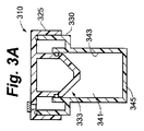
図3A、図3B、図3C、図3D、および図3Eは、細胞コンパートメント内の培養液の圧力および温度の少なくとも一方の変化に応答して自身の位置を自動的に変更する細胞コンパートメント容積調節機構を有して構成される細胞培養容器の実施形態を示す。図示される本実施形態では、流体移動部材は、細胞コンパートメント容積調節機構としての役割も果たすように構成される。図3Aの断面図では、細胞容器310は、本体330上に置かれるキャップ325を含む。細胞コンパートメント341は細胞容器310内の空間の容積を占め、側壁343と下壁345とに部分的に囲まれている。細胞コンパートメント容積調節機構333は細胞コンパートメント341の上方に位置する。図3Bでは、キャップ325は本体330と分離されて細胞コンパートメント341を露出させている。培養液315および細胞316は、この表示では十分に混合された懸濁液として示され、アクセスポート340によって細胞コンパートメント341内に配置されている。培養液315は最初、アクセスポート340の高さより低い、より好ましくは細胞コンパートメント側壁343の高さより低い、細胞コンパートメント341内の高さに位置することで、汚染リスクを低減する。図3Cに示すように、キャップ325は本体330と接触している。細胞316は、細胞コンパートメント341の下壁345に均一に分布されるように重力により低下している。気体320は培養液315の上方に位置する。さらに、気体320はオーバーフロータンク335と流体出路334を占有する。流体出路334は流体移動部材332とオーバーフロータンク335との間の空間である。流体移動部材332はキャップ325に装着される。図3Dは、培養液315と接触して培養液315を移動させる流体移動部材332を示す。培養液315の上面は流体出路334の方向に上昇しており、気体320の一部は流体出路334を介して細胞コンパートメント341から外に移動している。この場合、必須ではないが、キャップ325は本体330を密封する。上述の移動させられた気体を取り扱うオプションのいずれも使用可能である。本図では、キャップ325は、減菌フィルタ327によって覆われた排気口326を含む。減菌フィルタ327は好ましくは0.2ミクロンの細孔性材料である。同フィルタは、当該技術において既知な任意の方法で、好ましくは音波溶接でキャップ325に装着することができる。細胞コンパートメント341から移動させられた気体320は排気口326を介して細胞容器310を出る。図3Eでは、細胞コンパートメントシール338は細胞コンパートメント341の側壁343と接触して、流体管路334を閉鎖し、気体および培養液315の少なくとも一方がオーバーフロータンク335に入るのを防止している。オーバーフロータンクシール337は、オーバーフロータンク335が汚染されずにいるように確保する。キャップ325の下方運動によって流体移動部材332が非圧縮性培養液315に押し付けられると、非圧縮性培養液315は流体移動部材332に力を印加する。
3A, 3B, 3C, 3D, and 3E are cell compartment volume adjustment mechanisms that automatically change their position in response to changes in pressure and temperature of the culture medium in the cell compartment. The embodiment of the cell culture container comprised by having is shown. In the illustrated embodiment, the fluid movement member is configured to also serve as a cell compartment volume adjustment mechanism. In the cross-sectional view of FIG. 3A, the
細胞コンパートメント容積調節機構333の目的は、たとえば、培養液の温度が変化する、あるいは細胞コンパートメント341の壁が飛行中の圧力低下により外方に移動するときなどに、細胞コンパートメント341内の流体のポテンシャル・エネルギーの変動に応じて自動的に移動することである。よって、細胞コンパートメント容積調節機構は、細胞コンパートメント内の流体が上記機構に対して印加する力の変動に応じて同機構を移動させる構造を必要とする。そのポテンシャル・エネルギーはプロセス中に変化する。当業者であれば、流体移動部材が上記目的を満たすために利用可能な構造が多数あることを認識するであろう。
The purpose of the cell compartment
図3Eに示すように、流体移動部材332の少なくとも一部は細胞コンパートメント341の境界を形成する。細胞コンパートメント341内で流体(この場合、培養液)によって流体移動部材332に印加される力は、流体移動部材332を、細胞コンパートメント容積調節機構333としての構造に適した候補とする。流体移動部材332を、バルーンと同様に可撓材料から成る壁を有する密封中空体として構成することによって、流体移動部材332は細胞コンパートメント容積調節機構333となる。シリコンは、その生体適合性と優れた伸長および圧縮設定特性とにより適切な材料を提供する。この構造では、細胞コンパートメント341内の培養液315が収縮するにつれ、細胞コンパートメント容積調節機構333が膨張する。同様に、細胞コンパートメント341内の培養液315が膨張するにつれ、細胞コンパートメント容積調節機構333が収縮する。
As shown in FIG. 3E, at least a portion of the
細胞コンパートメント容積調節機構333のポテンシャル・エネルギーの最初の状態は、培養液に印加される力と、培養液の圧力とを示す。よって、最適パフォーマンスのために、ポテンシャル・エネルギーの最初の状態を制御する構造または方法が必要である。図示される本実施形態では、キャップ325が本体330にネジ留めされて、細胞コンパートメント容積調節機構333をポテンシャル・エネルギーの所望の最初の状態に設置する構造手段を提供することができる。キャップ325が下方に移動するにつれ、培養液315によって流体移動部材332に印加される力が同部材の容積を圧縮することによって、その内圧と蓄積されたポテンシャル・エネルギーとを増大させる。当業者であれば、ポテンシャル・エネルギーの所望の最初の状態を生成する際の精度は、各種機構の幾何学的形状を変更することによって向上させられると認識するであろう。たとえば、図示される本実施形態では、ネジが精密になる、細胞コンパートメント容積調節機構の内気体容積が大きくなる、あるいは細胞コンパートメント容積調節機構の壁の剛性が低下するほど、高い分解能が得られる。本図では、図3Cに示す細胞コンパートメント容積調節機構333の内容積V1は図3EではV2に低減されており、ポテンシャル・エネルギーを増大させている。
The initial state of potential energy of the cell compartment
上述したように、下壁支持部は、たとえば細胞コンパートメント容積調節機構333が増大したポテンシャル・エネルギーの状態にあるときなど、細胞コンパートメント341が加圧された場合に、下壁343が外方に湾曲するのを防止するのに有用である。存在する場合、下壁支持部は、本プロセス中を通じて細胞コンパートメント341の底部を平坦に保つのに十分な剛性を有するべきである。好ましくは、設計によって、細胞コンパートメント容積調節機構333が培養液315内に追いやられるときに圧力が増大する際、細胞が撓み領域で積層される程度まで下壁345が撓むことがないように確保する。下壁支持部を補強する構造リブまたはその他の手段の使用が、この事象を阻止することができる。
As described above, the lower wall support portion is bent outward when the
この状態で、細胞容器は温度および周囲圧の少なくとも一方の変動にさらされることに備えて、自動的に細胞コンパートメント内での圧力変動を制限する役割を果たすことができる。加えて、培養液冷却状態では、上述したように、可撓気体透過性下壁の不所望の位置変動が防止される。たとえば、培養液が冷却中に収縮すると、細胞コンパートメント容積調節機構はそのポテンシャル・エネルギーを低減しようとする。細胞コンパートメント容積調節機構内の増大した内圧は、収縮する培養液の方へ可撓壁を追いやることによって、可撓下壁が水平位置から外へ引っ張られるのを防止する役割を果たす。このように、下壁が薄い可撓気体透過性材料から成ると、細胞容器が水平位置に保持される限り、細胞を下壁上に均一に分布して保持することができる。培養液温度が上昇する場合、細胞コンパートメント容積調節機構は、最初の位置への滞留後、容積を圧縮することができるべきである。 In this state, the cell container can automatically serve to limit pressure fluctuations in the cell compartment in preparation for exposure to fluctuations in temperature and / or ambient pressure. In addition, in the culture solution cooled state, as described above, an undesirable position fluctuation of the flexible gas permeable lower wall is prevented. For example, when the culture medium shrinks during cooling, the cell compartment volume control mechanism attempts to reduce its potential energy. The increased internal pressure in the cell compartment volume control mechanism serves to prevent the flexible lower wall from being pulled out of the horizontal position by driving the flexible wall toward the shrinking culture. Thus, when the lower wall is made of a thin flexible gas permeable material, the cells can be uniformly distributed and held on the lower wall as long as the cell container is held in a horizontal position. If the culture temperature increases, the cell compartment volume adjustment mechanism should be able to compress the volume after residence in the initial position.
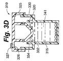
流体移動部材は、形状、位置のみを変更可能にする必要はなく、その壁は柔軟でなくてもよい。たとえば、図4Aの断面図に示すように、細胞容器410はバネ431に搭載される流体移動部材432を含み、細胞コンパートメント容積調節機構433を形成する。バネ431はキャップ425に装着される。キャップ425は本体430上に位置する。細胞コンパートメント441は細胞容器410内の空間の体積を占有し、側壁443および下壁445によって部分的に囲まれている。細胞コンパートメント容積調節機構433は下壁445の上方に位置する。図4Bでは、キャップ425は本体430から分離されて、細胞コンパートメント441を露出させる。本図では十分に混合された懸濁液として示される培養液415および細胞416は、アクセスポート440によって細胞コンパートメント441内に配置されている。最初、培養液415はアクセスポート440の高さより低い、より好ましくは細胞コンパートメント側壁443の高さより低い、細胞コンパートメント441内の高さに存在することによって、汚染リスクを軽減する。図4Cでは、キャップ425は本体430と接触している。細胞416は重力により下降して、細胞コンパートメント441の下壁445に均一に分布されている。気体420は培養液415の上方に存在する。さらに、気体420はオーバーフロータンク435および流体出路434も占有する。流体出路434は流体移動部材432とオーバーフロータンク435との間の空間である。好ましくは、すべての気体を除去するため、流体移動部材432の少なくとも一部は流体出路434の下方に存在する。図4Dでは、キャップ425は本体430によりさらなる下方移動を阻止され、バネ431は流体移動部材432を圧迫し、細胞コンパートメント441から気体を追いやり、非圧縮性培養液415によりさらなる下方移動を阻止される。細胞コンパートメント容積調節機構433は、蓄積されたポテンシャル・エネルギーの第1の位置に配置されている。本図ではOリングである細胞コンパートメントシール438は、培養液が細胞コンパートメント441内に保持され、オーバーフロータンク435内の気体420が細胞コンパートメント441内に再度進入できないように確保する。細胞コンパートメントシール438の使用の代替として、流体移動部材432と細胞コンパートメント441との間の緊密な許容間隙が、上述したようにこの目的を果たすために使用可能である。図4Dの第1の位置で、細胞コンパートメント容積調節機構433は細胞コンパートメント内でピストンのように作動するべく備えている。たとえば、培養液が温度低減中に収縮するにつれ、細胞コンパートメント容積調節機構433にかかる力が低減し、バネ431が延びるにつれ、細胞コンパートメント容積調節機構433は収縮する培養液の方に付勢されて、図4Eに示すように、そこで低減したポテンシャル・エネルギーの第2の位置で静止する。好ましくは、この第2の位置では、力が培養液に印加されて、可撓材料から成るときに下壁445が平坦を確実に維持するように、細胞コンパートメント容積調節機構433はいくらかのポテンシャル・エネルギーを保持し、下壁が気体透過性であるときも同様である。同様に、培養液の温度が上昇する場合、培養液のポテンシャル・エネルギーが上昇するにつれ、細胞コンパートメント容積調節機構433にかかる力が増大し、細胞コンパートメント容積調節機構433は上方へ移動して培養液を膨張させることによって、圧力増大を軽減する。
The fluid moving member does not need to be changeable only in shape and position, and its wall may not be flexible. For example, as shown in the cross-sectional view of FIG. 4A, the
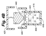
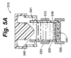
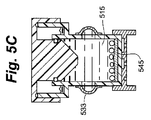
図5A、図5B、および図5Cは、培養液容積および周囲圧の少なくとも一方の変化に対応するように構成された細胞容器のさらに別の実施形態を示す。この細胞容器510の図示では、細胞コンパートメントの壁は細胞コンパートメント容積調節機構を含む。図5Aに示すように、培養液515と細胞516はアクセスポート540を介して細胞コンパートメント541に導入されている。本体530は細胞コンパートメント容積調節機構533を組み込み、同機構は図示される本実施形態では、当該技術に置いて一般的に既知な任意の手段によって液密に本体530の外周に固定される薄い可撓材料である。本体530の開口部は、培養液515が細胞コンパートメント容積調節機構533と直接接触するように存在する。細胞コンパートメント容積調節機構533は、ポテンシャル・エネルギーの第1の状態において第1の位置にある。下壁545は薄い可撓気体透過性材料から成る。下壁支持部550は下壁545を平坦な姿勢に保持する。図5Bでは、キャップ525は下方に移送され、流体移動部材532は気体520および少量の培養液515を細胞コンパートメント541からオーバーフロータンク535へと移動させている。緊密な間隙がオプションではあるが、本図では、細胞コンパートメントシール538が、気体が細胞コンパートメント541から戻るのを防ぐ。気体520が移動させられ、キャップ525がさらに下方へ移動しようとした後、非圧縮性培養液515は細胞コンパートメント容積調節機構533を付勢して、培養液515を収容するために第1の位置から第2の位置に膨張する。本図では、細胞コンパートメント容積調節機構533は、第2の位置の膨張状態まで伸長してポテンシャル・エネルギーと第1の位置に戻る能力とを増大させることのできる、シリコンなどの生体適合性のある弾性材料として構成される。図5Cの培養液515は、図5Bでの温度よりも冷却されている。培養液515の体積が収縮するにつれ、細胞コンパートメント容積調節機構533はポテンシャル・エネルギーを低減しようとしながら、最初の形状へと移動する。この運動は圧力の調節を助け、下壁545が可撓気体透過性材料から成るとき、気体透過性下壁545が上方へ引っ張られるのを阻止する。先の説明と同様、細胞コンパートメント容積調節機構の形状変化は好ましくは、培養液の予想される体積変化に関連づけられる。流体細胞コンパートメント容積調節機構の目的が可撓下壁を平坦に維持することである場合、流体細胞コンパートメント容積調節機構は好ましくは、培養プロセスおよび輸送プロセスの少なくとも一方の間中培養液に力を印加する。別の言い方をすれば、細胞コンパートメント容積調節機構533は、細胞コンパートメントの容積をさらに低減するようにポテンシャル・エネルギーを保持する。
5A, 5B, and 5C show yet another embodiment of a cell container configured to accommodate changes in at least one of culture volume and ambient pressure. In this illustration of the
実施形態は脱着可能キャップで記載されているが、当業者であれば、装置が閉システム用に構成できることを認識するであろう。たとえば、培養液と細胞は隔膜を通じて追加され、気体排気口を通じて移動させることができる。気体を装置から移動させた後、装置の容積は、細胞コンパートメント容積調節機構をポテンシャル・エネルギーの所望の最初の状態に設置するために物理的に変更することができ、その状態において、装置は予想される温度変化、または飛行中の圧力低下間の壁の移動に応じて細胞コンパートメントの容積を自動的に低減または膨張させようとする。本アプローチでは、装置は、容積を変更する、より具体的には細胞コンパートメントの容積を変更する構造手段を含む。容積を変更する構造手段を含める代わりに、加圧下で培養液を細胞コンパートメント内へ押しこみ、細胞コンパートメント容積調節機構をポテンシャル・エネルギーの所定の位置へ付勢する手段を採用することができる。 Although the embodiment is described with a removable cap, those skilled in the art will recognize that the device can be configured for a closed system. For example, the culture medium and cells can be added through the diaphragm and moved through the gas outlet. After moving the gas out of the device, the volume of the device can be physically changed to place the cell compartment volume adjustment mechanism in the desired initial state of potential energy, in which state the device is expected. It attempts to automatically reduce or expand the volume of the cell compartment in response to changes in temperature or wall movement during pressure drop during flight. In this approach, the device includes structural means for changing the volume, more specifically changing the volume of the cell compartment. Instead of including a structural means for changing the volume, a means for pushing the culture medium under pressure into the cell compartment and urging the cell compartment volume adjustment mechanism to a predetermined position of potential energy can be employed.
図6A、図6B、および図6Cは、細胞コンパートメント容積調節機構と、最初の細胞コンパートメント容積を変更する構造手段とが存在する閉システム用に構成される細胞容器の例を示す。構造手段は、細胞コンパートメント容積調節機構をポテンシャル・エネルギーの所望の状態に設置することによって、培養液容積の温度および周囲圧の少なくとも一方の変化に自動的に対応し、不所望な圧力影響を軽減することができる。図示される本実施形態では、図6Aは、培養液615と細胞616とが隔膜672を貫通するニードル671によって細胞コンパートメント641へと移送されていく様子を示す。培養液615が細胞コンパートメント641の容積全体を占めるように移動するにつれて、気体620は開放排気口673を介して細胞コンパートメント641から移動させられる。排気口673は、汚染物質が細胞コンパートメント641に入ることができず、開放または閉鎖させることができるように構成されるべきである。排気口673は蛇行路など、この目的を満たす任意の形で構成することができるが、好ましくは減菌フィルタ675、より好ましくは0.2ミクロンの細孔を有する疎水性フィルタを含むように構成される。細胞コンパートメント容積調節機構633は可撓壁を含む中空体である。細胞コンパートメント容積調節機構633の中空部は記号V1で示され、細胞コンパートメント容積調節機構633内に密封された気体の最初の内圧を示す。図6Bは、培養液615で満たされた細胞コンパートメント641を示す。細胞616は下壁645に定置している。その後、排気口673が閉鎖されている。図6Cは、細胞コンパートメント容積調節機構633のポテンシャル・エネルギーが増加した後の細胞容器610を示す。本例ではそうするために、装置が、高さの物理的低減を可能とする構造手段を組み込んでいる。上壁676と下壁645は互いに向かって付勢され、フィンガーロック678は尖突679と係合して、細胞容器610を容積が減少した新たな位置に固定している。細胞コンパートメント容積調節機構633は、記号V2で表される内容積が図6AのV1より小さくなるように圧縮している。尖突679は上壁676と下壁645との間の離散距離を選択することができるため、任意の所望の内容積を生成することができる。当業者であれば、上壁676と下壁645との間の距離を変更する様々な方法を採用できることを認識するであろう。たとえば、蛇腹状にすることによって、本体壁をピストン式またはその他の形で使用することが許容可能である。当業者であれば、細胞コンパートメントの容積変化が上壁と下壁の間の距離の変化を必要としないことも認識するであろう。たとえば、側壁は、細胞コンパートメント調節機構を最初のポテンシャル・エネルギーの所望の状態に追いやるように移動することもできる。図示されるアプローチはコンセプトを示すためのもので、本発明の範囲を制限しない。上壁676と下壁645との間の距離が生成された後、細胞コンパートメント容積調節機構633内で圧縮された気体はポテンシャル・エネルギーを増加させる。この状況下で、培養液容積を減少させると、細胞コンパートメント容積調節機構633の壁は培養液の方向に移動する。培養または輸送環境が培養液容積の増大または減少を招く可能性がある場合、細胞コンパートメント容積調節機構の蓄積されたポテンシャル・エネルギーは、その蓄積されたポテンシャル・エネルギーによって細胞コンパートメント容積調節機構633がいずれかの状況に対応することができるように設計されるべきである。たとえば、このような環境では、仮に培養液温度が上昇した場合、図6Cの細胞コンパートメント容積調節機構は内容積をV2よりもさらに低減することができる。
6A, 6B, and 6C show an example of a cell container configured for a closed system in which there is a cell compartment volume adjustment mechanism and structural means for changing the initial cell compartment volume. The structural means automatically accommodates changes in temperature and / or ambient pressure of the culture volume by placing the cell compartment volume regulation mechanism in the desired state of potential energy, reducing unwanted pressure effects can do. In the illustrated embodiment, FIG. 6A shows the
装置が細胞コンパートメント容積調節機構を所望のポテンシャル・エネルギーの状態に設置するための構造手段を含まない場合、それを実行する方法を採用することができる。たとえば、図6Bを参照すると、気体が移動させられるように、培養液が細胞コンパートメント641に導入されると、排気口673を閉鎖することができる。続いて、細胞コンパートメント容積調節機構633のポテンシャル・エネルギーを克服するのに十分な圧力下で培養液をさらに追加し、図6Cに示すように、培養液で内容積を圧縮することができる。
If the device does not include structural means for placing the cell compartment volume adjustment mechanism in the desired potential energy state, a method of doing so can be employed. For example, referring to FIG. 6B, the
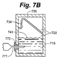
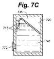
図7A、図7B、図7C、および図7Dは、排気口を必要とせずに気体を細胞コンパートメントから移動させることのできる閉システムの実施形態の例を示す。さらに、オーバーフロータンクは細胞コンパートメント容積調節機構として機能することもできる。図7Aは、使用前の細胞容器710の断面図である。オーバーフロータンク735は細胞コンパートメント741の上方に位置し、流体を流体出路734に向かって方向づける形状を有する。この場合、流体移動部材732はオーバーフロータンク735の先細りの壁であり、培養液が隔膜772を介して細胞コンパートメント741に入る際に気体を流体出路734の方へ方向づける役割を果たす。流体出路734は流体移動部材732の一部の上方に位置し、流体を細胞コンパートメント741からオーバーフロータンク735へ移動させることができる。図7Bは、隔膜772を貫通した後のニードル771によって培養液715が細胞コンパートメント741に追加されていく様子を示す。培養液715の高さが上昇するにつれ、気体720は体積が圧縮されて、流体出路734を介してオーバーフロータンク735へと送られる。細胞コンパートメント741に送られつつある培養液にかかる圧力は、気体が圧縮されているため、細胞コンパートメント741とオーバーフロータンク735内の圧力よりも大きくなければならない。図7Cは、培養液715が細胞コンパートメント741のすべてを占有している様子を示す。気体720と少量の培養液715がオーバーフロータンク735に存在している。ニードルは隔膜772から引き出されている。オーバーフロータンク内の圧力は、細胞コンパートメントおよびオーバーフロータンク内にある気体の元の体積に対する気体の体積に比例する。よって、培養液が細胞コンパートメントに入る際に培養液にかかる背圧は、細胞コンパートメントの容積およびオーバーフロータンクの容積の少なくとも一方を変動させることによって変更することができる。細胞コンパートメント内の圧力は、オーバーフロータンクの圧力とほぼ同じである。図7Dは、たとえば輸送または取扱中などに、非水平位置に配向される細胞容器710を示す。気体と培養液とを収容する円錐管のような従来の容器に比べて、気体720が培養液715内にある細胞に接触することが非常に困難になっていることが見てとれる。たとえばシリコンなどの可撓材料を使用してオーバーフロータンク735の一部を柔軟にすることによって、オーバーフロータンクは培養液容積の変化に対応することができる。たとえば、充填中に培養液にかかる圧力は、オーバーフロータンクの可撓部を、オーバーフロータンクがポテンシャル・エネルギーを蓄積する位置まで移動させることができる。そして、培養液の温度が低下し、体積が縮小すれば、オーバーフロータンクの可撓部は収縮する培養液の方へ移動する。もしくは、培養液の温度が上昇し、培養液がオーバーフロータンクの可撓部に力を印加すれば、培養液は体積を増大させることができる。このようにして、オーバーフロータンクは細胞コンパートメント容積調節機構となる。
7A, 7B, 7C, and 7D show an example of an embodiment of a closed system that can move gas out of the cell compartment without the need for an exhaust port. Furthermore, the overflow tank can also function as a cell compartment volume adjustment mechanism. FIG. 7A is a cross-sectional view of the
基本的に、本発明のどの実施形態の細胞コンパートメント容積調節機構も、細胞コンパートメント容積調節機構が第1の量のポテンシャル・エネルギーを蓄積し、細胞コンパートメントの第1の容積を定義する第1の位置から、細胞コンパートメント容積調節機構が第2の量のポテンシャル・エネルギーを蓄積し、細胞コンパートメントの第2の容積を定義する第2の位置まで移動することのできる構造手段を含む。適切な構造手段を生成する多数のオプションの中で、中空体と可撓壁、バネ、および弾性材料を示した。静置状態において、周囲の流体が細胞コンパートメント容積調節機構に印加する力は、細胞コンパートメント容積調節機構が周囲の流体に印加する力と等しい。この明細書全体を通じて、流体印加力(fluid exerting force)として培養液に言及している。しかしながら、流体は気体または液体であってもよい。よって、培養液という用語の使用は非限定的である。流体の温度と体積が増加しつつある状況では、細胞コンパートメント容積調節機構は細胞コンパートメントの容積が増大するように移動する。培養液の温度と体積が低下しつつある状況では、細胞コンパートメント容積調節機構は細胞コンパートメントの容積が減少するように移動する。好ましくは、細胞コンパートメント容積調節機構の設計は、培養液および/または流体の体積と、予測される温度変化とに主に基づく。たとえば、細胞が培養液で完全に満たされた細胞コンパートメント内で、37℃で培養され、22℃で輸送される場合、培養液の体積は温度変化に応じて約5%減少する。よって、培養液が追加された後に増大したポテンシャル・エネルギーの状態へと付勢された細胞コンパートメント容積調節機構は、培養液が収縮する際に細胞コンパートメントの容積を5%低減するように移動する能力を備えるべく構成されるべきである。細胞コンパートメント容積調節機構が、細胞コンパートメントの第1の容積が存在する第1の位置の上昇ポテンシャル・エネルギー状態から、細胞コンパートメントの第2の容積が存在する第2の位置の低下ポテンシャル・エネルギー状態まで移動する際、収縮する培養液容積によって明け渡された細胞コンパートメント空間の容積は、好ましくは細胞コンパートメント内の圧力変化を最小限にとどめ、細胞コンパートメント容積調節機構によって占有されるべきである。この例を続けると、培養液の容積が37℃で100mlであり、22℃の輸送温度が望ましい場合、細胞コンパートメント容積調節機構は温度低下中に、温度低下に関連する培養液容積の5%損失を賄うために細胞コンパートメントから約5mlの培養液を移動させるように、第1の位置から第2の位置に移動することができるべきである。下壁が可撓気体透過性材料から成るとき、好ましくは細胞コンパートメント容積調節機構は、培養液にいくらかの力を印加することによって、気体透過性下壁が培養液によって印加される力によって平坦に維持されるよう確保するように、培養および輸送の少なくとも一方の間中いくらかのポテンシャル・エネルギーを保持しておくべきである。さらに、細胞コンパートメント容積調節機構は逆に移動することもできる。たとえば、培養液の温度が上昇するとき、そのポテンシャル・エネルギーの増加が細胞コンパートメント容積調節機構のポテンシャル・エネルギーを圧倒して、細胞コンパートメント容積調節機構を、細胞コンパートメントの第1の容積が存在する第1の位置から細胞コンパートメントの第2の容積が存在する第2の位置まで移動させる。このようにして、細胞コンパートメント内で起こり得る圧力増加は、培養液容積温度の上昇間に緩和される。好ましくは、細胞コンパートメント容積調節機構により、細胞コンパートメントの容積を繰り返し増加および/または減少させることによって、使用中の周囲温度の変動および/または圧力変化を調整する。 Basically, the cell compartment volume adjustment mechanism of any embodiment of the present invention has a first position where the cell compartment volume adjustment mechanism accumulates a first amount of potential energy and defines a first volume of the cell compartment. The cell compartment volume adjustment mechanism includes structural means capable of accumulating a second amount of potential energy and moving to a second position defining a second volume of the cell compartment. Among the many options for generating suitable structural means, hollow bodies and flexible walls, springs, and elastic materials have been shown. In the stationary state, the force that the surrounding fluid applies to the cell compartment volume adjustment mechanism is equal to the force that the cell compartment volume adjustment mechanism applies to the surrounding fluid. Throughout this specification, the culture medium is referred to as the fluid applying force. However, the fluid may be a gas or a liquid. Thus, the use of the term culture medium is non-limiting. In situations where the temperature and volume of the fluid are increasing, the cell compartment volume adjustment mechanism moves to increase the volume of the cell compartment. In situations where the temperature and volume of the culture are decreasing, the cell compartment volume regulation mechanism moves so that the volume of the cell compartment decreases. Preferably, the design of the cell compartment volume regulation mechanism is mainly based on the volume of the culture medium and / or fluid and the expected temperature change. For example, when cells are cultured at 37 ° C. and transported at 22 ° C. in a cell compartment completely filled with culture medium, the volume of the culture medium decreases by about 5% in response to temperature changes. Thus, the cell compartment volume regulation mechanism that is biased to the increased potential energy state after the culture medium is added has the ability to move to reduce the volume of the cell compartment by 5% as the culture medium contracts. Should be configured to provide The cell compartment volume regulation mechanism is from a rising potential energy state at a first location where the first volume of the cell compartment is present to a decreasing potential energy state at a second location where the second volume of the cell compartment is present. When moving, the volume of the cell compartment space surrendered by the shrinking culture volume should preferably be occupied by the cell compartment volume regulation mechanism, minimizing pressure changes within the cell compartment. Continuing with this example, if the culture volume is 100 ml at 37 ° C. and a transport temperature of 22 ° C. is desired, the cell compartment volume control mechanism loses 5% of the culture volume associated with the temperature drop during the temperature drop. It should be possible to move from the first position to the second position so that about 5 ml of culture broth is moved from the cell compartment to cover. When the lower wall is made of a flexible gas permeable material, preferably the cell compartment volume adjustment mechanism is applied by applying some force to the culture so that the gas permeable lower wall is flattened by the force applied by the culture. Some potential energy should be maintained throughout at least one of culture and transport to ensure that it is maintained. Furthermore, the cell compartment volume regulation mechanism can also move in reverse. For example, when the temperature of the culture medium rises, the increase in potential energy overwhelms the potential energy of the cell compartment volume control mechanism, causing the cell compartment volume control mechanism to be in the first volume of the cell compartment. Move from one position to a second position where a second volume of cell compartment is present. In this way, the pressure increase that can occur in the cell compartment is mitigated during the increase in the culture volume temperature. Preferably, the cell compartment volume adjustment mechanism adjusts the ambient temperature fluctuations and / or pressure changes during use by repeatedly increasing and / or decreasing the volume of the cell compartment.
細胞コンパートメント調節機構をポテンシャル・エネルギーの所望かつ所定の最初の状態に設置することは、細胞コンパートメント容積調節機構をポテンシャル・エネルギーの所望の状態に設置することのできる物理構造を装置に含むことによって達成することができる。開システムでは、細胞コンパートメント容積調節機構を上記状態に設置するための多数のオプションが存在する。ネジ式キャップと本体は互いに対して移動し、細胞コンパートメント容積調節機構のポテンシャル・エネルギーを変更する優れた解決策を提供することができる。閉システムでは、フィンガーロック、ピストン体、または蛇腹体は、装置を物理的に操作して、細胞コンパートメント容積調節機構をポテンシャル・エネルギーの所望の状態に設置ための多数の構造オプションの例である。細胞コンパートメント容積調節機構を所望のポテンシャル・エネルギー状態に設置する物理的構造がない場合、培養液の圧力を上げる非限定的な方法が説明されている。 Placing the cell compartment regulation mechanism in the desired and predetermined initial state of potential energy is accomplished by including in the device a physical structure that can place the cell compartment volume regulation mechanism in the desired state of potential energy. can do. In an open system, there are a number of options for installing the cell compartment volume adjustment mechanism in the above state. The screw cap and body can move relative to each other and provide an excellent solution to alter the potential energy of the cell compartment volume adjustment mechanism. In a closed system, finger locks, piston bodies, or bellows bodies are examples of numerous structural options for physically manipulating the device to place the cell compartment volume adjustment mechanism in the desired state of potential energy. In the absence of a physical structure that places the cell compartment volume control mechanism in the desired potential energy state, a non-limiting method of raising the culture pressure is described.
細胞コンパートメント容積調節機構は主に、培養液で完全に満たされた細胞コンパートメントという状況で説明してきたが、当業者であれば、液体および/または気体の存在下でも使用可能であることを認識するであろう。たとえば、様々な培養用途のように、細胞コンパートメントからの気体の完全除去によって恩恵を受けない用途があるかもしれない。細胞を培養および輸送させることができる場合に、細胞容器は最も頑強である。この細胞容器は、細胞を培養装置から輸送装置に移送する必要を排除することにより、汚染リスクを最小限にすることができる。培養液の最適量は、培養状態と輸送状態とでは異なるかもしれない。たとえば、輸送中に気体を移動させる必要がある場合、輸送状態よりも培養状態の方が少量の培養液が存在するかもしれない。これは、細胞コンパートメント調節機構の設計に影響を及ぼしかねない検討事項である。ポテンシャル・エネルギーの最初の状態は、非圧縮性流体(すなわち、培養液で満たされた細胞コンパートメント)と、圧縮性流体(すなわち、気体を含む細胞コンパートメント)とに対して移動させられたとき、2つの同一構造の細胞コンパートメント調節機構間で異なる。最適な培養および輸送用の細胞容器を構成する方法の1つは、細胞培養条件に合わせた機構と、輸送条件に合わせた機構の2つの細胞コンパートメント調節機構を含むことである。 Although the cell compartment volume regulation mechanism has been described primarily in the context of a cell compartment completely filled with culture medium, one skilled in the art will recognize that it can also be used in the presence of liquids and / or gases. Will. For example, there may be applications that do not benefit from complete removal of gas from the cell compartment, such as various culture applications. Cell containers are the most robust when cells can be cultured and transported. This cell container can minimize the risk of contamination by eliminating the need to transfer cells from the culture device to the transport device. The optimal amount of culture medium may differ between the culture state and the transport state. For example, if it is necessary to move gas during transport, there may be a smaller amount of culture in the culture state than in the transport state. This is a consideration that may affect the design of cellular compartmental regulatory mechanisms. The initial state of potential energy is 2 when moved against an incompressible fluid (ie, a cell compartment filled with culture medium) and a compressible fluid (ie, a cell compartment containing a gas). It differs between two identically structured cell compartment regulatory mechanisms. One way to construct a cell container for optimal culture and transport is to include two cell compartment regulation mechanisms: a mechanism tailored to cell culture conditions and a mechanism tailored to transport conditions.
培養液が細胞コンパートメントを完全に満たさずに細胞が培養される場合、ルーチンの取扱中に装置を動かすと、培養液が細胞を均一な分布から変位させるような運動を行う可能性がある。この結果、細胞面密度(細胞/cm2)が、望ましくない未制御のレベルにまで増大するおそれがある。液体中の渦状運動がより容易に発生し易いため、細胞コンパートメントが円筒状であるときはさらに問題である。1つのオプションは、円筒形状の使用を避けることである。しかしながら、それは製造上のオプションを限定することになりかねず、円筒形状は製造上コスト効率が良い場合が多い。たとえば、Oリング付きの標準的な放射シールは通常、円筒体の円形形状に頼っている。さらに、円錐状流体移動部材と円筒状細胞コンパートメントの利点は上述したとおりである。もう1つのオプションは、流体移動部材などを使用して気体を細胞コンパートメントから完全に移動させることによって、培養液に波が発生する気体−液体界面をなくして、上記の状況を緩和することである。しかしながら、培養液で装置を完全に満たすことによってこの問題に対処することは、培養液のコストが高いとき、あるいは従来のフラスコ培養の場合と、細胞数に対する培養液容積の割合を同一に維持することが望ましいときは最適な解決策ではないかもしれない。さらに別のオプションは、排気された細胞コンパートメントの存在下に比べ波の形成が低減されるように適切に構成された細胞コンパートメント調節機構の使用によって気体を加圧することである。本アプローチでは、最適圧力は試行錯誤を経て決定されるであろう。 If cells are cultured without the culture medium completely filling the cell compartment, moving the device during routine handling can cause the culture medium to move so as to displace the cells from a uniform distribution. This can result in an increase in cell surface density (cells / cm 2 ) to undesirable uncontrolled levels. It is even more problematic when the cell compartment is cylindrical because vortex motion in the liquid is more likely to occur. One option is to avoid the use of a cylindrical shape. However, it can limit manufacturing options and the cylindrical shape is often cost effective for manufacturing. For example, a standard radiant seal with an O-ring typically relies on a circular cylindrical shape. Further, the advantages of the conical fluid moving member and the cylindrical cell compartment are as described above. Another option is to alleviate the situation by eliminating the gas-liquid interface where waves are generated in the culture by moving the gas completely out of the cell compartment, such as using a fluid transfer member. . However, addressing this problem by completely filling the apparatus with culture broth keeps the ratio of the culture volume to the number of cells the same when the cost of the culture is high or in the case of conventional flask culture. It may not be the best solution when it is desirable. Yet another option is to pressurize the gas by use of a cell compartment regulatory mechanism that is appropriately configured to reduce wave formation compared to the presence of evacuated cell compartments. In this approach, the optimal pressure will be determined through trial and error.
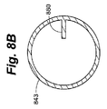
別の好適なオプションとして、図8Aおよび図8Bに、たとえば培養に使用されるときなど、装置内に気体が残留する場合に培養液の移動を制限することによって、細胞が均一の分布から変位する可能性を最小限にとどめ、より広い範囲の培養プロトコルを可能にするバッフル(baffle)を含む細胞容器の実施形態を示す。図8Aの断面図は、本体830から取り外されたキャップ825と、培養コンパートメント841内にあるバッフル880とを示す。断面A−Aを図8Bに示す。バッフル880は、この場合側壁843から培養コンパートメント841へと突出する。本図では、培養コンパートメント841は円筒状である。バッフル880は、ルーチンの取扱中に培養液の回転を阻害し得る。よって、培養液は、細胞が培養液の回転力を受けるのを阻止するために気体を移動させる必要はない。バッフルは下壁845と接触する、あるいは下壁845から延在することができる。好ましくは、バッフル880と下壁845との間の間隙によって、細胞を装置から容易に回収することができる。この間隙により、細胞と培養液が自由にバッフルの下を通過する間、ユーザは装置を傾斜させ、任意の位置からピペットで取ることによって細胞を回収することができる。バッフル880の最下部と下壁845との間の間隙は、予測される培養液の高さに基づき選択されるべきである。たとえば、培養液が1.0cmの高さに存在するとすれば、下壁845とバッフル880との間の距離は1.0cm未満とすべきである。このようにして、バッフルは培養中に培養液と接触する。しかしながら、装置が気体透過性でない場合、気体交換用の気体−液体界面に頼る培養における培養液の通常の高さは約2mm〜3mmであるため、バッフルは好ましくは下壁と接触すべきである。よって、バッフルと下壁との間の小さな間隙でさえ、細胞が高面密度で再分布されるのを阻止することができない。好適な実施形態では、バッフルは、対向する細胞コンパートメント壁間の距離の50%を超えない距離で、細胞コンパートメント壁から突出する垂直壁である。
As another preferred option, in FIGS. 8A and 8B, the cells are displaced from a uniform distribution by limiting the movement of the culture medium when gas remains in the apparatus, such as when used in culture, for example. Fig. 4 shows an embodiment of a cell container comprising a baffle that minimizes the potential and allows for a wider range of culture protocols. The cross-sectional view of FIG. 8A shows the
また、表面に付着されることを選択する、あるいは低面密度で存在することを選択する大量の細胞を輸送する、あるいは培養および輸送することが所望される場合がある。このような事象では、細胞コンパートメントは、細胞が置かれる多数の装着面を組み込むことができる。図9Aおよび図9Bは、互いに積み重なる骨格(scaffold)を組み込んだ実施形態を示す。ウィルソンらの‘814は、この幾何学的形状を最も適切に達成する方法に関する指針を提供する。骨格は任意の材料であってもよいが、安価で製造し易いため、ポリスチレンが適した選択肢である。骨格は、細胞が懸濁液であるか、あるいは付着性細胞であるかに応じて培養処理される組織であってもよいし、なくてもよい。装置は、流体移動部材および細胞コンパートメント容積調節機構の少なくとも一方を有して構成することができる。好ましくは、用途が培養段階を含む、あるいは移送中に酸素の入手可能性が望まれるとき、装置本体は気体透過性材料から成る。当業者は細胞コンパートメント容積調節機構として採用する任意の構造を組み込むことができるが、本体が気体透過性材料から成るとき、本体は細胞コンパートメント容積調節機構として機能することもできる。図9Aに示される実施形態では、垂直に配置された骨格905の山が細胞コンパートメント941内に存在する。気体920、培養液915、および細胞が細胞コンパートメント941内に存在する。流体移動部材932と共に構成されるキャップ925は、まだ装着されていない。装置の気体透過性壁を温度の上昇または低下に応じて移動させるには、壁の少なくとも一部を可撓材料で製造して、骨格の縁部と装置壁の可撓部との間に距離を残すのが最善である。この距離は必須ではないが、培養液の体積が収縮する場合、可撓壁が内方に移動する能力を高める。しかしながら、最初の距離は、装置上にキャップを設置するという単純な行為によって設定することができる。図9Bでは、流体移動部材932が気体を移動させ、少量の培養液915をオーバーフロータンク935に追いやっている。本体930の壁の一部は、可撓性であり、好ましくは気体透過性であり、増大したポテンシャル・エネルギーの位置まで拡張されているが、仮に培養液温度が上昇すれば、さらに拡張し、ポテンシャル・エネルギーを増加させることができる。培養液温度が低下する場合は、壁が骨格の方に移動することができる。移動することを意図する壁の一部にとって、シリコンは適した選択材料である。シリコンは気体透過性、可撓性、および高い弾性を有する。シリコンが装置内にあるとき、組織が処理される場合、骨格905の表面化学が同時係属ウィルソンらの‘856に記載される方法を採用することによるガンマまたはe線の照射間に変化しないように注意を払うべきである。
It may also be desirable to transport, or culture and transport large quantities of cells that choose to adhere to a surface or choose to exist at a low areal density. In such an event, the cell compartment can incorporate multiple mounting surfaces on which the cells are placed. 9A and 9B show an embodiment that incorporates scaffolds that are stacked on top of each other. Wilson et al. '814 provides guidance on how to best achieve this geometry. The skeleton may be any material, but polystyrene is a suitable choice because it is inexpensive and easy to manufacture. The skeleton may or may not be a tissue that is cultured according to whether the cell is a suspension or an adherent cell. The device can be configured with at least one of a fluid transfer member and a cell compartment volume adjustment mechanism. Preferably, the device body is made of a gas permeable material when the application involves a culturing stage or when oxygen availability during transfer is desired. One skilled in the art can incorporate any structure employed as a cell compartment volume adjustment mechanism, but when the body is comprised of a gas permeable material, the body can also function as a cell compartment volume adjustment mechanism. In the embodiment shown in FIG. 9A, a pile of vertically arranged
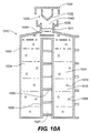
骨格表面積に対する気体透過性表面積の割合が図10Aおよび図10Bに示される実施形態での割合を超える状態に置かれることを選択する細胞を培養および/または輸送することが所望される場合がある。たとえば、非常に大量の膵島の輸送は、膵島を配置する複数層の気体透過性面を有する装置によって達成することができる。図10Aおよび図10Bは、これがどのように達成されるかについての実施形態を示す。ウィルソンの‘848を参照すると、さらなる指針が得られる。図10Aでは、2つの細胞コンパートメント1004がマニホルド1009によって接続されて積み重ねられている。ウィルソンの‘848に記載されるように、装置本体1030のどの壁も気体透過性材料で構成することができる。気体空間1007は細胞コンパートメント1004を分離する。骨格支持部1008は、骨格1007を略平坦な状態に保持する役割を果たす。キャップ1025は装着されていない。細胞容器1010は、細胞1016と培養液1015が細胞コンパートメント1004に導入されるように配向されている。培養液は、アクセスポート1040の入口より下のレベルに存在する。キャップ1025に装着される細胞コンパートメント容積調節機構1033は先細りの壁を含み、流体移動部材1032を形成する。首部1011はオーバーフロータンク1035を含む。図10Bでは、細胞容器1010は、細胞1016と培養液1015が既に骨格1005の上方に至るように配向されている。キャップ1025は本体1030を封止し、気体1020と少量の培養液1015は流体移動部材1032によってオーバーフロータンク1035に移動させられている。この図では、流体移動部材は、細胞コンパートメント容積調節機構1033としての機能も果たすように、可撓壁を有する中空体として構成されている。上述したように、細胞コンパートメント容積調節機構1033は、培養液容積の変化に応じて延長または後退することができる。
It may be desirable to culture and / or transport cells that choose to be placed in a state where the ratio of gas permeable surface area to skeletal surface area exceeds that in the embodiment shown in FIGS. 10A and 10B. For example, the transport of very large islets can be achieved by a device having multiple layers of gas permeable surfaces that place the islets. 10A and 10B show an embodiment of how this is achieved. See Wilson's' 848 for further guidance. In FIG. 10A, two
流体移動部材の使用は、気体が存在しないとき、あるいは装置内の特定領域に隔離されているときにより適切に機能する、細胞培養用に設計された特定の装置にとって非常に有用である。たとえば、米国特許出願第11/454,964号および11/478,823号は、気体を捕捉するように細胞培養装置の位置を操作することによって装置の不所望な領域への気体の移動を最小化する幾何学的形状を記載している。当業者であれば、本発明の流体移動部材が、‘964および’823に記載される装置やコーニング(Corning)社(登録商標)製の市販のHyperflask(登録商標)のように、細胞培養のために使用される装置から気体を移動させるのに有用であることを認識するであろう。よって、気体が望ましくない細胞培養装置の領域に入るのを防止する好適な方法は、流体移動部材を含むキャップとオーバーフロータンクを含むアクセスポートとを有する細胞培養装置を構成することである。その後、細胞容器(すなわち、細胞培養装置)は以下のようにして使用することができる。培養液が装置から外にあふれださない位置にアクセスポートを配向させ、細胞および培養液を細胞培養装置に導入し、キャップがアクセスポートを覆うことによって、気体が流体移動部材により細胞コンパートメントから移動させられるようにキャップを装置に装着する。次に、装置を、骨格が水平になり、細胞の生存に適した雰囲気中に配置されるような位置に再配向させることができる。より好適な方法によると、細胞容器装置のアクセスポートは、装置が培養位置にある(すなわち、水平)間、培養液を装置に追加させることによって、より簡易な自動化または片手での充填を可能にするように、垂直に配向させられる。 The use of fluid transfer members is very useful for certain devices designed for cell culture that function better when no gas is present or when they are isolated to specific areas within the device. For example, US patent application Ser. Nos. 11 / 454,964 and 11 / 478,823 minimize the movement of gas to undesired areas of the device by manipulating the position of the cell culture device to trap the gas. The geometric shape to be converted is described. A person skilled in the art can use the fluid transfer member of the present invention for cell culture, such as the apparatus described in '964 and' 823, or the commercially available Hyperflas® from Corning®. It will be appreciated that it is useful for moving gas out of the equipment used for this purpose. Thus, a preferred method of preventing gas from entering the undesired cell culture device region is to construct a cell culture device having a cap that includes a fluid moving member and an access port that includes an overflow tank. Thereafter, the cell container (that is, the cell culture device) can be used as follows. Orient the access port to a position where the culture fluid does not overflow outside the device, introduce cells and culture fluid into the cell culture device, and the cap covers the access port, allowing gas to move from the cell compartment by the fluid moving member Attach the cap to the device so that The device can then be reoriented to a position where the scaffold is horizontal and placed in an atmosphere suitable for cell survival. According to a more preferred method, the access port of the cell container device allows easier automation or filling with one hand by allowing the culture medium to be added to the device while the device is in the culture position (ie horizontal). To be oriented vertically.
本文書に記載の細胞コンパートメント容積調節機構の使用は、気体が細胞の近傍に存在する、あるいは培養液内で形成するのを防止する際に最も適切に作動される細胞培養用に設計された特定の装置にとって非常に有用である。たとえば冷たい培養液が装置に追加され、その後インキュベーター内で温められて、気体保持能力を低下させたり気泡を形成したりする場合など、培養中に培養液温度が変化する際に、気体が不所望な領域に滞留する可能性がある。本文書に記載の細胞コンパートメント容積調節機構は、このような種類の事象を防ぐため、培養液を加圧するために使用することができる。その目的で、細胞コンパートメント容積調節機構は、培養液の温度が上昇する際、増大したポテンシャル・エネルギーの状態に至り、および、気体抜きが防止あるいは最小化されるように培養液の圧力を調節する培養液への力を印加するように構成されるべきである。よって、細胞培養用途では、培養液の圧力を調節し、細胞コンパートメント容積調節機構を細胞培養装置に組み込み、培養液および細胞を細胞培養装置内に配置し、装置を保温して細胞をインキュベートすることができるように、細胞コンパートメント容積調節機構を構成するであろう。 The use of the cell compartment volume control mechanism described in this document is not specifically designed for cell cultures that operate best in preventing gas from being in the vicinity of cells or forming in the culture medium. It is very useful for this device. Gas is not desired when the culture temperature changes during culture, for example when a cold culture is added to the device and then warmed in an incubator to reduce gas retention capacity or form bubbles. There is a possibility of staying in a new area. The cell compartment volume regulation mechanism described in this document can be used to pressurize the culture to prevent this type of event. To that end, the cell compartment volume control mechanism adjusts the culture fluid pressure to reach an increased potential energy state and prevent or minimize outgassing as the culture temperature increases. Should be configured to apply force to the culture. Therefore, in cell culture applications, the pressure of the culture solution is adjusted, the cell compartment volume adjustment mechanism is incorporated into the cell culture device, the culture solution and cells are placed in the cell culture device, the device is kept warm and the cells are incubated. Would constitute a cell compartment volume regulation mechanism.
輸送中、細胞が均一に分布されて滞留するため、細胞容器を水平位置に維持することが好ましい。これは、細胞が非常に高い密度で重力により下降させられる際、たとえば細胞が装置の隅に定置する際に起こり得る損傷を避けるのに有用である。米国特許第6,490,880号および米国特許出願第10/829,752号は、輸送の際に水平位置に装置を配向させておくジンバル機構の使用を説明している。細胞容器を輸送する好適な方法では、移送中を通じて下壁および骨格の少なくとも一方を水平位置に設置する。この配向で、細胞を所望の表面密度で均一に分布させておくことができる。よって、細胞容器を使用する一方法は、培養液容積の変動を相殺し、培養液および細胞を導入し、任意で細胞培養を実行し、その後細胞容器をジンバル機構内に配置し、細胞容器を所望の目的地に輸送するために気体および/または細胞コンパートメント容積調節機構を移動させる流体移動部材とともに細胞容器を構成することであろう。 It is preferable to maintain the cell container in a horizontal position because the cells are uniformly distributed and stay during transportation. This is useful to avoid damage that can occur when cells are lowered by gravity at a very high density, for example when cells are placed in the corners of the device. U.S. Patent No. 6,490,880 and U.S. Patent Application No. 10 / 829,752 describe the use of a gimbal mechanism that keeps the device oriented in a horizontal position during transport. In a preferred method of transporting the cell container, at least one of the lower wall and the skeleton is placed in a horizontal position throughout the transfer. With this orientation, the cells can be uniformly distributed at a desired surface density. Thus, one method of using a cell container is to offset the variation in the culture volume, introduce the culture medium and cells, optionally perform cell culture, then place the cell container in the gimbal mechanism, The cell container would be configured with a fluid moving member that moves the gas and / or cell compartment volume adjustment mechanism for transport to the desired destination.
当業者であれば、本発明の各種態様、特徴、および構成要素のための材料選択の具体的な選択の際に、広範な公開情報が指針として入手可能であることを認識するであろう。細胞培養装置または生物学的材料を収容する容器のために使用されるすべての材料は任意である。ガンマ線を照射可能なUSPクラスVI材料が好ましい。 One of ordinary skill in the art will recognize that extensive public information is available as guidance in the specific selection of material selections for the various aspects, features, and components of the present invention. All materials used for cell culture devices or containers containing biological material are optional. USP class VI materials capable of gamma irradiation are preferred.
本発明を以下の非限定的実施例を参照してさらに説明する。
(実施例)
実施例1
流体移動部材を有する細胞培養容器を以下のように構成して、図11に示す。キャップ1125には、図示されるような寸法で流体移動部材1132を組み込んだ。本体1130は透明なポリカーボネート棒材で製造した。細胞コンパートメント1141は、直径1.40インチ、高さ2.46インチで、本体1130に円筒状の開口部を機械加工で形成することにより作製した。下壁1145を70ショアAデュロメータ、および0.004インチ厚のジメチルシリコンで製造し、ポリカーボネート下壁支持部1150から、表面積10cm2の気体透過性シリコン下壁1145を圧迫することによって本体1130に装着した。下壁支持部1150は下壁1145の真下の領域で0.13インチ厚とし、8個のネジで本体1130に取り付け、本体1130の外周に均等に間隔をおいて配置した。40mlの培養液を細胞コンパートメント1141内に配置するため50mlのピペットを使用した。培養液温度は約37℃とした。培養液は、下壁1145の上方1.58インチの高さ、および細胞コンパートメント側壁1143の最後部の下方0.36インチの高さに滞留した。オーバーフロータンクシール1137がさらなる回転を阻止するまで、キャップ1125を本体1130にネジ留めした。細胞コンパートメントシール1138は、流体が細胞コンパートメント1141を出入りするのを阻止した。キャップ1125のさらなる移動が停止した時点で、流体移動部材1132が下壁1145に最も近づく地点は1.2インチだった。透明な細胞コンパートメント壁1143を介して視覚検査したところ、すべての気体が細胞コンパートメント1141から移動させられ、少量の培養液が流体出路1134を通って移動することによりオーバーフロータンク1135内に移送されていた。続いて、温度変動の問題を実証するため、培養液の温度を最初の約37℃から約22℃に低減した。培養液が縮小するにつれ、気体透過性下壁1145が平坦位置から流体移動機構1132の方に引き寄せられるのが観察された。この例は、培養液で完全に充填される必要なく、いかにして気体を細胞容器から移動させることができるか、および、どのように培養液の温度変化が薄い気体透過性材料から成る下壁の最適配向に影響を及ぼし得るかを実証する。
実施例2
気温変化から生じる培養液の温度変化に対応する細胞コンパートメント容積調節機構の能力を実証するためにテストを実行した。図12に示すように、テスト装置を構成し、キャップ1225に可撓シリコン壁から成る中空流体移動部材1232、70ショアAデュロメータを組み込むことによって細胞コンパートメント調節機構1233を作製した。流体移動部材1232のプロファイルは実施例1に記載したとおりの寸法とした。中空細胞コンパートメント調節機構1233の壁厚は均一で0.10インチとした。細胞コンパートメント1241と、下壁1245と、下壁支持部1250と、オーバーフロータンク1235とを含む細胞容器の本体は実施例1に従い構成した。実施例1に記載するように、40mlの培養液を細胞コンパートメント1241内に配置した。装置内の培養液および気体は約37℃とした。オーバーフロータンクシール1237がさらなる回転を阻止するまで、キャップ1225を本体1230にネジ留めした。細胞コンパートメントシール1238は、流体が細胞コンパートメント1241を出入りするのを阻止した。すべての気体および少量の培養液がオーバーフロータンク1235内に移動させられたのが観察された。細胞コンパートメント容積調節機構1233の内容積を、テスト孔1239に密封して装着される血圧計で測定されたように、約3.0P.S.I.圧に圧縮した。細胞容器を約22℃の周囲雰囲気に配置した。培養液がその温度に達したとき、細胞コンパートメント容積調節機構1233の内容積内の圧力が約2.0P.S.I.に低下し、細胞コンパートメント容積調節機構1233が細胞コンパートメント1241内に拡張し、収縮する培養液によって明け渡された空間を占めた。下壁1245は実施例1で至ったような弓状とは対照的に、平坦なままだった。このことは、薄い気体透過性材料から成る下壁を平坦状態で維持する能力を含め、温度変化の不所望な影響を阻止するために、最初に蓄積されたポテンシャル・エネルギーの位置から、低減されたが正のポテンシャル・エネルギーの第2の位置まで自動的に移動する細胞コンパートメント容積調節機構の能力を実証するものである。
The invention will be further described with reference to the following non-limiting examples.
(Example)
Example 1
A cell culture vessel having a fluid moving member is configured as follows and shown in FIG. The
Example 2
Tests were performed to demonstrate the ability of the cell compartment volume control mechanism to respond to changes in culture temperature resulting from temperature changes. As shown in FIG. 12, a test apparatus was constructed, and a cell
当業者であれば、精神から逸脱せずに多数の変形が可能であると理解するであろう。したがって、本発明の範囲を図示され記載される実施形態に限定することは意図されていない。むしろ、本発明の範囲は、添付の請求項およびその等価物によって解釈されるべきである。 Those skilled in the art will appreciate that many variations are possible without departing from the spirit. Accordingly, it is not intended that the scope of the invention be limited to the embodiments shown and described. Rather, the scope of the present invention should be construed by the appended claims and their equivalents.
Claims (4)
キャップと、
前記キャップに接続される容積調節機構と、
構造手段であって、該構造手段により、細胞コンパートメント容積調節機構が移動し、前記機構のポテンシャル・エネルギーの状態を変更することが可能である、前記構造手段と
を備える容器用密封装置。 A container sealing device,
A cap,
A volume adjusting mechanism connected to the cap;
A container sealing device comprising: a structural means, wherein the structural means moves a cell compartment volume adjustment mechanism and is capable of changing a potential energy state of the mechanism.
側壁と底部とによって少なくとも部分的に囲まれた細胞コンパートメントと、
アクセスポートと、
オーバーフロータンクと、該オーバーフロータンクに前記細胞コンパートメントを接続する流体出路と、
流体移動部材と、
構造手段であって、該構造手段により、前記流体移動部材と前記細胞コンパートメントとの間の距離を変更することが可能である、前記構造手段と
を備える細胞容器。 A cell container,
A cell compartment at least partially surrounded by a sidewall and a bottom;
An access port;
An overflow tank and a fluid outlet connecting the cell compartment to the overflow tank;
A fluid moving member;
A cell container comprising structural means, wherein the structural means is capable of changing a distance between the fluid moving member and the cell compartment.
空間の容積を占め、側壁と底部とによって少なくとも部分的に囲まれた細胞コンパートメントと、
アクセスポートと、
細胞コンパートメント容積調節機構と、
構造手段であって、該構造手段により、前記細胞コンパートメント容積調節機構が移動し、前記機構のポテンシャル・エネルギーの状態を変更することが可能である、前記構造手段と
を備える細胞容器。 A cell container,
A cell compartment that occupies a volume of space and is at least partially surrounded by side walls and a bottom;
An access port;
A cell compartment volume control mechanism;
A cell container comprising: structural means, wherein the structural means moves the cell compartment volume adjustment mechanism and is capable of changing a state of potential energy of the mechanism.
Applications Claiming Priority (1)
| Application Number | Priority Date | Filing Date | Title |
|---|---|---|---|
| PCT/US2008/062687 WO2009136907A1 (en) | 2008-05-05 | 2008-05-05 | Cell container |
Publications (2)
| Publication Number | Publication Date |
|---|---|
| JP2011519557A true JP2011519557A (en) | 2011-07-14 |
| JP2011519557A5 JP2011519557A5 (en) | 2011-08-25 |
Family
ID=41264815
Family Applications (1)
| Application Number | Title | Priority Date | Filing Date |
|---|---|---|---|
| JP2011507397A Pending JP2011519557A (en) | 2008-05-05 | 2008-05-05 | Cell container |
Country Status (6)
| Country | Link |
|---|---|
| EP (1) | EP2274413B1 (en) |
| JP (1) | JP2011519557A (en) |
| CN (1) | CN102015997B (en) |
| AU (1) | AU2008355994B2 (en) |
| CA (1) | CA2722907C (en) |
| WO (1) | WO2009136907A1 (en) |
Cited By (10)
| Publication number | Priority date | Publication date | Assignee | Title |
|---|---|---|---|---|
| JP2013128457A (en) * | 2011-12-22 | 2013-07-04 | Hitachi Ltd | Packaging container |
| WO2016117281A1 (en) * | 2015-01-21 | 2016-07-28 | 東洋製罐グループホールディングス株式会社 | Cell culture container, cell culture method, and method for using cell culture container |
| WO2016157322A1 (en) * | 2015-03-27 | 2016-10-06 | 株式会社日立製作所 | Closed-system culture vessel, transport method, and automated culturing device |
| JP2016208920A (en) * | 2015-05-08 | 2016-12-15 | 株式会社北川鉄工所 | Container sealing structure |
| JP2019017342A (en) * | 2017-07-20 | 2019-02-07 | テルモ株式会社 | Fragile product holding device equipped with liquid receiving space |
| JP2019017343A (en) * | 2017-07-20 | 2019-02-07 | テルモ株式会社 | Fragile product holding device equipped with guide mechanism |
| JP2019019107A (en) * | 2017-07-20 | 2019-02-07 | テルモ株式会社 | Fragile product holding device including liquid holding space |
| WO2019124303A1 (en) * | 2017-12-18 | 2019-06-27 | テルモ株式会社 | Fragile-object retaining device provided with injection mechanism |
| JP2019170167A (en) * | 2018-03-27 | 2019-10-10 | 株式会社北川鉄工所 | Cell culture vessel |
| JP2020174603A (en) * | 2019-04-19 | 2020-10-29 | 大日本印刷株式会社 | Biological material container, biological material container kit and container containing equipment |
Families Citing this family (9)
| Publication number | Priority date | Publication date | Assignee | Title |
|---|---|---|---|---|
| US8778669B2 (en) | 2009-07-22 | 2014-07-15 | Corning Incorporated | Multilayer tissue culture vessel |
| JP5775295B2 (en) | 2010-12-22 | 2015-09-09 | テルモ株式会社 | Membrane tissue storage and transport container and storage and transport method |
| US20150231628A1 (en) * | 2012-09-11 | 2015-08-20 | Hitachi, Ltd. | Biological Sample Packaging Container and Biological Sample Conveyance Method Using Same |
| US9005550B2 (en) | 2012-10-29 | 2015-04-14 | Corning Incorporated | Multi-layered cell culture vessel with manifold grips |
| US10260038B2 (en) | 2013-05-10 | 2019-04-16 | Whitehead Institute For Biomedical Research | Protein modification of living cells using sortase |
| JP5768174B1 (en) | 2014-06-24 | 2015-08-26 | 日本写真印刷株式会社 | Culture vessel |
| GB201709140D0 (en) * | 2017-06-08 | 2017-07-26 | Vitrolife As | Lid for culture dish |
| SG11201913105UA (en) * | 2017-07-20 | 2020-02-27 | Terumo Corp | Fragile object preserving device having seal mechanism |
| CN110626618A (en) * | 2019-08-07 | 2019-12-31 | 浙江厚达智能科技股份有限公司 | Traditional Chinese medicine storage bag with overflow storage space and traditional Chinese medicine bagging method |
Citations (7)
| Publication number | Priority date | Publication date | Assignee | Title |
|---|---|---|---|---|
| JP2004513889A (en) * | 2000-08-25 | 2004-05-13 | オルガン リカヴァリー システムス インコーポレイテッド | Apparatus and method for maintaining and / or restoring organ viability |
| JP2005516596A (en) * | 2002-02-01 | 2005-06-09 | オーツー−スキャン ゲーエムベーハー | Lid element |
| JP2006217845A (en) * | 2005-02-09 | 2006-08-24 | Hitachi Medical Corp | Method and apparatus for culturing adsorptive cell |
| WO2007015770A1 (en) * | 2005-07-26 | 2007-02-08 | Corning Incorporated | Multilayered cell culture apparatus |
| JP2007511205A (en) * | 2003-10-08 | 2007-05-10 | ウィルソン ウォルフ マニュファクチャリング コーポレイション | Method and apparatus for culturing cells using gas permeable substances |
| JP2007269327A (en) * | 2006-03-30 | 2007-10-18 | Japan Tissue Engineering:Kk | Packaging container for cultured tissue, unit for use in the container, and packaging body for cultured tissue using the container |
| JP2008048653A (en) * | 2006-08-23 | 2008-03-06 | Fukoku Co Ltd | Culture vessel having inner face made of cycloolefin resin, and gene transfer method and cell culture method using the vessel |
Family Cites Families (7)
| Publication number | Priority date | Publication date | Assignee | Title |
|---|---|---|---|---|
| US4321330A (en) * | 1980-04-04 | 1982-03-23 | Baker Fraser L | Tissue culture device |
| US4578588A (en) * | 1983-08-12 | 1986-03-25 | Galkin Benjamin M | Volume reduction in liquid scintillation counting |
| GB2214240A (en) * | 1988-01-06 | 1989-08-31 | Laurence Patrick Wettern | Wine aeration pump |
| US5615791A (en) * | 1994-08-10 | 1997-04-01 | Vatelot; Yves | System of a bottle and of an associated co-operating device |
| US6145688A (en) * | 1996-07-17 | 2000-11-14 | Smith; James C. | Closure device for containers |
| US6053888A (en) * | 1998-08-05 | 2000-04-25 | Kong; Carl Cheung Tung | Variable volume bottle and related medical fluid infusion system |
| DE29817223U1 (en) * | 1998-09-24 | 1998-11-19 | Marotzki Stefan Dr | Device for taking up a cell culture |
-
2008
- 2008-05-05 EP EP08769296.8A patent/EP2274413B1/en active Active
- 2008-05-05 JP JP2011507397A patent/JP2011519557A/en active Pending
- 2008-05-05 CA CA2722907A patent/CA2722907C/en active Active
- 2008-05-05 CN CN200880129061.0A patent/CN102015997B/en active Active
- 2008-05-05 WO PCT/US2008/062687 patent/WO2009136907A1/en active Application Filing
- 2008-05-05 AU AU2008355994A patent/AU2008355994B2/en active Active
Patent Citations (7)
| Publication number | Priority date | Publication date | Assignee | Title |
|---|---|---|---|---|
| JP2004513889A (en) * | 2000-08-25 | 2004-05-13 | オルガン リカヴァリー システムス インコーポレイテッド | Apparatus and method for maintaining and / or restoring organ viability |
| JP2005516596A (en) * | 2002-02-01 | 2005-06-09 | オーツー−スキャン ゲーエムベーハー | Lid element |
| JP2007511205A (en) * | 2003-10-08 | 2007-05-10 | ウィルソン ウォルフ マニュファクチャリング コーポレイション | Method and apparatus for culturing cells using gas permeable substances |
| JP2006217845A (en) * | 2005-02-09 | 2006-08-24 | Hitachi Medical Corp | Method and apparatus for culturing adsorptive cell |
| WO2007015770A1 (en) * | 2005-07-26 | 2007-02-08 | Corning Incorporated | Multilayered cell culture apparatus |
| JP2007269327A (en) * | 2006-03-30 | 2007-10-18 | Japan Tissue Engineering:Kk | Packaging container for cultured tissue, unit for use in the container, and packaging body for cultured tissue using the container |
| JP2008048653A (en) * | 2006-08-23 | 2008-03-06 | Fukoku Co Ltd | Culture vessel having inner face made of cycloolefin resin, and gene transfer method and cell culture method using the vessel |
Cited By (16)
| Publication number | Priority date | Publication date | Assignee | Title |
|---|---|---|---|---|
| JP2013128457A (en) * | 2011-12-22 | 2013-07-04 | Hitachi Ltd | Packaging container |
| WO2016117281A1 (en) * | 2015-01-21 | 2016-07-28 | 東洋製罐グループホールディングス株式会社 | Cell culture container, cell culture method, and method for using cell culture container |
| WO2016157322A1 (en) * | 2015-03-27 | 2016-10-06 | 株式会社日立製作所 | Closed-system culture vessel, transport method, and automated culturing device |
| JPWO2016157322A1 (en) * | 2015-03-27 | 2017-06-22 | 株式会社日立製作所 | Closed culture vessel, transport method, and automatic culture apparatus |
| JP2016208920A (en) * | 2015-05-08 | 2016-12-15 | 株式会社北川鉄工所 | Container sealing structure |
| JP7039202B2 (en) | 2017-07-20 | 2022-03-22 | テルモ株式会社 | Fragile holding device with liquid receiving space |
| JP2019017343A (en) * | 2017-07-20 | 2019-02-07 | テルモ株式会社 | Fragile product holding device equipped with guide mechanism |
| JP2019019107A (en) * | 2017-07-20 | 2019-02-07 | テルモ株式会社 | Fragile product holding device including liquid holding space |
| JP2019017342A (en) * | 2017-07-20 | 2019-02-07 | テルモ株式会社 | Fragile product holding device equipped with liquid receiving space |
| WO2019124303A1 (en) * | 2017-12-18 | 2019-06-27 | テルモ株式会社 | Fragile-object retaining device provided with injection mechanism |
| JPWO2019124303A1 (en) * | 2017-12-18 | 2021-01-14 | テルモ株式会社 | Fragile holding device with injection mechanism |
| JP7241029B2 (en) | 2017-12-18 | 2023-03-16 | テルモ株式会社 | Fragile retention device with injection mechanism |
| JP2019170167A (en) * | 2018-03-27 | 2019-10-10 | 株式会社北川鉄工所 | Cell culture vessel |
| JP7088713B2 (en) | 2018-03-27 | 2022-06-21 | 株式会社北川鉄工所 | Cell culture vessel |
| JP2020174603A (en) * | 2019-04-19 | 2020-10-29 | 大日本印刷株式会社 | Biological material container, biological material container kit and container containing equipment |
| JP7310258B2 (en) | 2019-04-19 | 2023-07-19 | 大日本印刷株式会社 | BIOLOGICAL CONTAINER, BIOLOGICAL CONTAINER KIT AND EQUIPMENT CONTAINER |
Also Published As
| Publication number | Publication date |
|---|---|
| CN102015997B (en) | 2016-08-10 |
| AU2008355994A1 (en) | 2009-11-12 |
| EP2274413B1 (en) | 2017-07-26 |
| WO2009136907A1 (en) | 2009-11-12 |
| EP2274413A4 (en) | 2013-03-20 |
| CA2722907A1 (en) | 2009-11-12 |
| CA2722907C (en) | 2016-07-12 |
| EP2274413A1 (en) | 2011-01-19 |
| AU2008355994B2 (en) | 2014-08-14 |
| CN102015997A (en) | 2011-04-13 |
Similar Documents
| Publication | Publication Date | Title |
|---|---|---|
| JP2011519557A (en) | Cell container | |
| AU2019240734B2 (en) | Cell culture methods and devices utilizing gas permeable materials | |
| US8999703B2 (en) | Cell container | |
| AU2012254908B2 (en) | Cell culture methods and devices utilizing gas permeable materials | |
| AU2017203120B2 (en) | Cell culture methods and devices utilizing gas permeable materials |
Legal Events
| Date | Code | Title | Description |
|---|---|---|---|
| A521 | Written amendment |
Free format text: JAPANESE INTERMEDIATE CODE: A523 Effective date: 20110422 |
|
| A621 | Written request for application examination |
Free format text: JAPANESE INTERMEDIATE CODE: A621 Effective date: 20110422 |
|
| RD04 | Notification of resignation of power of attorney |
Free format text: JAPANESE INTERMEDIATE CODE: A7424 Effective date: 20120112 |
|
| A977 | Report on retrieval |
Free format text: JAPANESE INTERMEDIATE CODE: A971007 Effective date: 20120530 |
|
| A131 | Notification of reasons for refusal |
Free format text: JAPANESE INTERMEDIATE CODE: A131 Effective date: 20120612 |
|
| A02 | Decision of refusal |
Free format text: JAPANESE INTERMEDIATE CODE: A02 Effective date: 20121106 |