JP2011507686A - Filter device - Google Patents
Filter device Download PDFInfo
- Publication number
- JP2011507686A JP2011507686A JP2010539689A JP2010539689A JP2011507686A JP 2011507686 A JP2011507686 A JP 2011507686A JP 2010539689 A JP2010539689 A JP 2010539689A JP 2010539689 A JP2010539689 A JP 2010539689A JP 2011507686 A JP2011507686 A JP 2011507686A
- Authority
- JP
- Japan
- Prior art keywords
- filter
- filter device
- substrate
- attached
- filter element
- Prior art date
- Legal status (The legal status is an assumption and is not a legal conclusion. Google has not performed a legal analysis and makes no representation as to the accuracy of the status listed.)
- Pending
Links
- 239000000758 substrate Substances 0.000 claims abstract description 128
- 239000012530 fluid Substances 0.000 claims abstract description 104
- 238000001914 filtration Methods 0.000 claims abstract description 31
- 238000004891 communication Methods 0.000 claims description 63
- 239000000463 material Substances 0.000 claims description 33
- 238000003466 welding Methods 0.000 claims description 10
- 238000007789 sealing Methods 0.000 claims description 5
- 238000000926 separation method Methods 0.000 claims 2
- 239000010410 layer Substances 0.000 description 28
- 230000010261 cell growth Effects 0.000 description 23
- 239000002609 medium Substances 0.000 description 20
- 229910052751 metal Inorganic materials 0.000 description 13
- 239000002184 metal Substances 0.000 description 13
- 239000004033 plastic Substances 0.000 description 13
- 229920003023 plastic Polymers 0.000 description 13
- 230000004888 barrier function Effects 0.000 description 9
- 238000000034 method Methods 0.000 description 9
- 239000002131 composite material Substances 0.000 description 8
- 229920002678 cellulose Polymers 0.000 description 7
- 239000001913 cellulose Substances 0.000 description 7
- 230000005540 biological transmission Effects 0.000 description 5
- -1 polytetrafluoroethylene Polymers 0.000 description 5
- XLYOFNOQVPJJNP-UHFFFAOYSA-N water Chemical compound O XLYOFNOQVPJJNP-UHFFFAOYSA-N 0.000 description 5
- 239000007788 liquid Substances 0.000 description 4
- 239000000047 product Substances 0.000 description 4
- 239000002699 waste material Substances 0.000 description 4
- 239000004677 Nylon Substances 0.000 description 3
- 239000004743 Polypropylene Substances 0.000 description 3
- 229920001778 nylon Polymers 0.000 description 3
- 229920000642 polymer Polymers 0.000 description 3
- 229920001155 polypropylene Polymers 0.000 description 3
- 239000011148 porous material Substances 0.000 description 3
- 230000008569 process Effects 0.000 description 3
- 229910052782 aluminium Inorganic materials 0.000 description 2
- XAGFODPZIPBFFR-UHFFFAOYSA-N aluminium Chemical compound [Al] XAGFODPZIPBFFR-UHFFFAOYSA-N 0.000 description 2
- 230000008859 change Effects 0.000 description 2
- 239000011248 coating agent Substances 0.000 description 2
- 238000000576 coating method Methods 0.000 description 2
- 230000006835 compression Effects 0.000 description 2
- 238000007906 compression Methods 0.000 description 2
- 239000011888 foil Substances 0.000 description 2
- 229920001903 high density polyethylene Polymers 0.000 description 2
- 239000004700 high-density polyethylene Substances 0.000 description 2
- 238000003475 lamination Methods 0.000 description 2
- 229920001684 low density polyethylene Polymers 0.000 description 2
- 239000004702 low-density polyethylene Substances 0.000 description 2
- 238000004519 manufacturing process Methods 0.000 description 2
- 239000012528 membrane Substances 0.000 description 2
- 229920000728 polyester Polymers 0.000 description 2
- 229920006254 polymer film Polymers 0.000 description 2
- 239000002356 single layer Substances 0.000 description 2
- 238000003860 storage Methods 0.000 description 2
- 239000005909 Kieselgur Substances 0.000 description 1
- 239000004695 Polyether sulfone Substances 0.000 description 1
- VYPSYNLAJGMNEJ-UHFFFAOYSA-N Silicium dioxide Chemical compound O=[Si]=O VYPSYNLAJGMNEJ-UHFFFAOYSA-N 0.000 description 1
- 230000002745 absorbent Effects 0.000 description 1
- 239000002250 absorbent Substances 0.000 description 1
- 230000009471 action Effects 0.000 description 1
- 239000000853 adhesive Substances 0.000 description 1
- 230000001070 adhesive effect Effects 0.000 description 1
- 230000000712 assembly Effects 0.000 description 1
- 238000000429 assembly Methods 0.000 description 1
- 230000009286 beneficial effect Effects 0.000 description 1
- 239000011230 binding agent Substances 0.000 description 1
- 230000015556 catabolic process Effects 0.000 description 1
- 238000011109 contamination Methods 0.000 description 1
- 238000009295 crossflow filtration Methods 0.000 description 1
- 238000005520 cutting process Methods 0.000 description 1
- 238000006731 degradation reaction Methods 0.000 description 1
- 238000013461 design Methods 0.000 description 1
- 238000011161 development Methods 0.000 description 1
- 230000000694 effects Effects 0.000 description 1
- 239000000706 filtrate Substances 0.000 description 1
- 239000003365 glass fiber Substances 0.000 description 1
- 230000005484 gravity Effects 0.000 description 1
- 239000001963 growth medium Substances 0.000 description 1
- 238000010348 incorporation Methods 0.000 description 1
- 230000001788 irregular Effects 0.000 description 1
- 238000012986 modification Methods 0.000 description 1
- 230000004048 modification Effects 0.000 description 1
- 239000004745 nonwoven fabric Substances 0.000 description 1
- 235000015097 nutrients Nutrition 0.000 description 1
- 239000002245 particle Substances 0.000 description 1
- 235000019362 perlite Nutrition 0.000 description 1
- 239000010451 perlite Substances 0.000 description 1
- 229920006255 plastic film Polymers 0.000 description 1
- 239000002985 plastic film Substances 0.000 description 1
- 238000004023 plastic welding Methods 0.000 description 1
- 229920006393 polyether sulfone Polymers 0.000 description 1
- 239000002861 polymer material Substances 0.000 description 1
- 229920001343 polytetrafluoroethylene Polymers 0.000 description 1
- 239000004810 polytetrafluoroethylene Substances 0.000 description 1
- 230000002028 premature Effects 0.000 description 1
- 238000012545 processing Methods 0.000 description 1
- 238000003672 processing method Methods 0.000 description 1
- 238000004080 punching Methods 0.000 description 1
- 238000011160 research Methods 0.000 description 1
- 229920005989 resin Polymers 0.000 description 1
- 239000011347 resin Substances 0.000 description 1
- 238000009958 sewing Methods 0.000 description 1
- 239000002904 solvent Substances 0.000 description 1
- 238000007655 standard test method Methods 0.000 description 1
- 238000012360 testing method Methods 0.000 description 1
- 238000011144 upstream manufacturing Methods 0.000 description 1
Images


Classifications
-
- B—PERFORMING OPERATIONS; TRANSPORTING
- B01—PHYSICAL OR CHEMICAL PROCESSES OR APPARATUS IN GENERAL
- B01D—SEPARATION
- B01D29/00—Filters with filtering elements stationary during filtration, e.g. pressure or suction filters, not covered by groups B01D24/00 - B01D27/00; Filtering elements therefor
- B01D29/01—Filters with filtering elements stationary during filtration, e.g. pressure or suction filters, not covered by groups B01D24/00 - B01D27/00; Filtering elements therefor with flat filtering elements
- B01D29/05—Filters with filtering elements stationary during filtration, e.g. pressure or suction filters, not covered by groups B01D24/00 - B01D27/00; Filtering elements therefor with flat filtering elements supported
-
- B—PERFORMING OPERATIONS; TRANSPORTING
- B01—PHYSICAL OR CHEMICAL PROCESSES OR APPARATUS IN GENERAL
- B01D—SEPARATION
- B01D25/00—Filters formed by clamping together several filtering elements or parts of such elements
- B01D25/22—Cell-type filters
- B01D25/26—Cell-type stack filters
-
- B—PERFORMING OPERATIONS; TRANSPORTING
- B01—PHYSICAL OR CHEMICAL PROCESSES OR APPARATUS IN GENERAL
- B01D—SEPARATION
- B01D29/00—Filters with filtering elements stationary during filtration, e.g. pressure or suction filters, not covered by groups B01D24/00 - B01D27/00; Filtering elements therefor
- B01D29/01—Filters with filtering elements stationary during filtration, e.g. pressure or suction filters, not covered by groups B01D24/00 - B01D27/00; Filtering elements therefor with flat filtering elements
- B01D29/016—Filters with filtering elements stationary during filtration, e.g. pressure or suction filters, not covered by groups B01D24/00 - B01D27/00; Filtering elements therefor with flat filtering elements with corrugated, folded or wound filtering elements
-
- B—PERFORMING OPERATIONS; TRANSPORTING
- B01—PHYSICAL OR CHEMICAL PROCESSES OR APPARATUS IN GENERAL
- B01D—SEPARATION
- B01D29/00—Filters with filtering elements stationary during filtration, e.g. pressure or suction filters, not covered by groups B01D24/00 - B01D27/00; Filtering elements therefor
- B01D29/01—Filters with filtering elements stationary during filtration, e.g. pressure or suction filters, not covered by groups B01D24/00 - B01D27/00; Filtering elements therefor with flat filtering elements
- B01D29/03—Filters with filtering elements stationary during filtration, e.g. pressure or suction filters, not covered by groups B01D24/00 - B01D27/00; Filtering elements therefor with flat filtering elements self-supporting
- B01D29/031—Filters with filtering elements stationary during filtration, e.g. pressure or suction filters, not covered by groups B01D24/00 - B01D27/00; Filtering elements therefor with flat filtering elements self-supporting with corrugated, folded filtering elements
-
- B—PERFORMING OPERATIONS; TRANSPORTING
- B01—PHYSICAL OR CHEMICAL PROCESSES OR APPARATUS IN GENERAL
- B01D—SEPARATION
- B01D29/00—Filters with filtering elements stationary during filtration, e.g. pressure or suction filters, not covered by groups B01D24/00 - B01D27/00; Filtering elements therefor
- B01D29/11—Filters with filtering elements stationary during filtration, e.g. pressure or suction filters, not covered by groups B01D24/00 - B01D27/00; Filtering elements therefor with bag, cage, hose, tube, sleeve or like filtering elements
- B01D29/13—Supported filter elements
- B01D29/15—Supported filter elements arranged for inward flow filtration
- B01D29/21—Supported filter elements arranged for inward flow filtration with corrugated, folded or wound sheets
- B01D29/213—Supported filter elements arranged for inward flow filtration with corrugated, folded or wound sheets having a concertina shape
-
- B—PERFORMING OPERATIONS; TRANSPORTING
- B01—PHYSICAL OR CHEMICAL PROCESSES OR APPARATUS IN GENERAL
- B01D—SEPARATION
- B01D29/00—Filters with filtering elements stationary during filtration, e.g. pressure or suction filters, not covered by groups B01D24/00 - B01D27/00; Filtering elements therefor
- B01D29/50—Filters with filtering elements stationary during filtration, e.g. pressure or suction filters, not covered by groups B01D24/00 - B01D27/00; Filtering elements therefor with multiple filtering elements, characterised by their mutual disposition
-
- B—PERFORMING OPERATIONS; TRANSPORTING
- B01—PHYSICAL OR CHEMICAL PROCESSES OR APPARATUS IN GENERAL
- B01D—SEPARATION
- B01D35/00—Filtering devices having features not specifically covered by groups B01D24/00 - B01D33/00, or for applications not specifically covered by groups B01D24/00 - B01D33/00; Auxiliary devices for filtration; Filter housing constructions
- B01D35/14—Safety devices specially adapted for filtration; Devices for indicating clogging
- B01D35/157—Flow control valves: Damping or calibrated passages
- B01D35/1573—Flow control valves
-
- B—PERFORMING OPERATIONS; TRANSPORTING
- B01—PHYSICAL OR CHEMICAL PROCESSES OR APPARATUS IN GENERAL
- B01D—SEPARATION
- B01D2201/00—Details relating to filtering apparatus
- B01D2201/02—Filtering elements having a conical form
-
- B—PERFORMING OPERATIONS; TRANSPORTING
- B01—PHYSICAL OR CHEMICAL PROCESSES OR APPARATUS IN GENERAL
- B01D—SEPARATION
- B01D29/00—Filters with filtering elements stationary during filtration, e.g. pressure or suction filters, not covered by groups B01D24/00 - B01D27/00; Filtering elements therefor
- B01D29/50—Filters with filtering elements stationary during filtration, e.g. pressure or suction filters, not covered by groups B01D24/00 - B01D27/00; Filtering elements therefor with multiple filtering elements, characterised by their mutual disposition
- B01D29/52—Filters with filtering elements stationary during filtration, e.g. pressure or suction filters, not covered by groups B01D24/00 - B01D27/00; Filtering elements therefor with multiple filtering elements, characterised by their mutual disposition in parallel connection
Abstract
フィルター装置が開示される。本装置は、非透過性フィルム間に封入することができる、少なくとも1つの実質的に平坦な濾材を備える。いくつかの実施形態では、流体を導入して濾過させるため、及びこの濾過された流体を排水するためのポートが含まれる。様々な基材がこの中で少なくとも1つの濾材と協働して使用されて、装置の性能を強化することができる。少なくとも1つのフィルター装置を収容するように構成された様々な装置もまた開示される。 A filter device is disclosed. The apparatus comprises at least one substantially flat filter medium that can be encapsulated between non-permeable films. In some embodiments, ports are included for introducing and filtering fluid and for draining the filtered fluid. Various substrates can be used in cooperation with at least one filter medium in this to enhance the performance of the device. Various devices configured to accommodate at least one filter device are also disclosed.
Description
本開示は概して流体フィルター装置、並びにその作製及び使用方法に関する。より詳細には、本開示は、ポリマーフィルムを含む、使い捨て流体フィルター装置に関する。 The present disclosure relates generally to fluid filter devices and methods of making and using the same. More particularly, the present disclosure relates to a disposable fluid filter device that includes a polymer film.
現在、研究、開発、及び製造において利用可能な、多くの流体フィルター製品が存在する。これらの製品のいくつかは、流体源を浄化する又は殺菌するように設計されている、ある種の使い捨て濾材を有する。使い捨て濾材は典型的に、再利用可能な金属ハウジング内に配置される。金属ハウジングは、処理される流体に接触し、典型的に濾材の交換中に洗浄されるか、又は消毒される。フィルター交換と製品のバッチ変更との間の汚染のリスクを低減するために、再利用可能なハウジングと流体の接触をなくす、使い捨てフィルターカートリッジが開発されてきた。このようなフィルターは、比較的大きく、かつ重いことが多く、それが取扱いに関してあまり望ましいものではないものにしている。比較的大きな寸法は、フィルターの処分時に、廃棄物の増加をもたらす可能性がある。このようなフィルターはまた、ホールドアップ容積を有し(即ち、運転中のカートリッジ組立品内に収容される流体)、これは濾過プロセスの完了時の回収が難しい。 There are currently many fluid filter products available for research, development, and manufacturing. Some of these products have certain disposable filter media that are designed to purify or sterilize fluid sources. The disposable filter media is typically placed in a reusable metal housing. The metal housing contacts the fluid to be treated and is typically cleaned or sterilized during filter media replacement. In order to reduce the risk of contamination between filter changes and product batch changes, disposable filter cartridges have been developed that eliminate reusable housing and fluid contact. Such filters are relatively large and often heavy, making it less desirable for handling. The relatively large dimensions can result in increased waste upon disposal of the filter. Such filters also have a hold-up volume (i.e., fluid contained within an operating cartridge assembly), which is difficult to recover at the completion of the filtration process.
したがって、取扱いが容易で、費用効率が高く、直接的(例えば、濾材の廃棄低減)及び間接的(例えば、ホールドアップ容積の低減)の両方で廃棄物を低減する使い捨てフィルター製品が、引き続き必要とされている。 Accordingly, there is a continuing need for disposable filter products that are easy to handle, cost effective, and reduce waste both directly (eg, reducing filter media waste) and indirectly (eg, reducing holdup volume). Has been.
本開示は、概して流体フィルター装置、並びにその作製及び使用方法に関する。より詳細には、本開示は、ポリマーフィルムを含む、使い捨て流体フィルター装置に関する。本開示のフィルター装置は、より大きな効率性の低いフィルター要素を、より小さな、より薄いフィルター要素と交換することによって、濾過作業において、使用され、廃棄される材料のサイズ及び量を低減することができる。 The present disclosure relates generally to fluid filter devices and methods of making and using the same. More particularly, the present disclosure relates to a disposable fluid filter device that includes a polymer film. The filter device of the present disclosure can reduce the size and amount of material used and discarded in filtration operations by replacing a larger, less efficient filter element with a smaller, thinner filter element. it can.
本願は、少なくとも1つの濾材、並びにそれに取り付けられる少なくとも第1及び第2の非透過性フィルムを有するフィルター装置を開示する。いくつかの実施形態では、この装置の性能を強化するように構成された、少なくとも1つの排水基材が更に含まれる。いくつかの実施形態では、非透過性フィルムの少なくとも1つは、流体がフィルター装置に入る又はフィルター装置を出ることを可能にするように構成された、少なくとも1つの流体連通ポートが更に備わる。非透過性フィルムは一体的に取り付けられて、フィルター装置を実質的に平面的に封入することができる。いくつかの実施形態では、少なくとも1つの濾材が、支持部、更なる取り付け領域、又は濾過、流れ若しくは排水の強化をもたらすように構成された少なくとも1つの基材に更に取り付けられてもよい。いくつかの実施形態では、濾材は平面的に配置されたプリーツを有するが、複数の濾材構成、例えば平坦なシート媒体がうまく採用され得るということが企図される。実質的に平坦な構成を維持する一方で、複数のフィルター要素を含む実施形態が採用されて、濾過表面積を更に増加させてもよい。開示されたフィルター装置の実施形態を含み、その使用を容易にするように構成された様々な装置も開示されるが、開示されたフィルター装置のいくつかの実施形態は、独立して使用されてもよいということが想定される。開示されたフィルター装置は、実質的に平坦な構成で使用されてもよく、その一方で、いくつかの実施形態は、代替物として成形された様々な形状物に適合するように操作できる、可撓性特性のものであるということが理解される。 The present application discloses a filter device having at least one filter medium and at least first and second non-permeable films attached thereto. In some embodiments, at least one drainage substrate is further included that is configured to enhance the performance of the device. In some embodiments, at least one of the non-permeable films further comprises at least one fluid communication port configured to allow fluid to enter or exit the filter device. The non-permeable film can be attached integrally to encapsulate the filter device in a substantially planar manner. In some embodiments, the at least one filter media may be further attached to a support, a further attachment region, or at least one substrate configured to provide filtration, flow or drainage enhancement. In some embodiments, the filter media has pleats arranged in a plane, but it is contemplated that multiple filter media configurations, such as flat sheet media, can be successfully employed. While maintaining a substantially flat configuration, embodiments including multiple filter elements may be employed to further increase the filtration surface area. Various devices are also disclosed, including embodiments of the disclosed filter device and configured to facilitate its use, but some embodiments of the disclosed filter device may be used independently. It is assumed that it is good. The disclosed filter device may be used in a substantially flat configuration, while some embodiments may be manipulated to accommodate a variety of shapes molded as alternatives. It is understood that it is of a flexible characteristic.
本開示のこれらの態様及び他の態様は、以下の「発明を実施するための形態」から明らかとなるだろう。しかしながら、上記要約は、所有権が主張される主題への限定として決して解釈されるべきでなく、主題は、手続処理中に補正され得る添付の特許請求の範囲によってのみ規定される。 These and other aspects of the present disclosure will become apparent from the following Detailed Description. However, the above summary should in no way be construed as a limitation on the claimed subject matter, which is defined only by the appended claims that may be modified during the processing.
本明細書全体にわたって、類似の参照数字が類似の要素を指す添付図面が参照される。
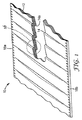
図1は、折り返し14aを有する、平面的に配置されたプリーツ14を有する少なくとも1つの濾材12を備える、実質的に平坦なフィルター要素を示す。濾材12は、単独若しくは組み合わせで、選択された用途の様々な濾過、構造的な支持、排水、及び流れの要件を満たすために好適である単一材料若しくは複数の材料の複合体で形成されてもよい。このような材料には、例えば、膜(例えば、ナイロン、ポリエーテルスルホン、ポリテトラフルオロエチレン、ポリプロピレン等)、不織布、ポリマーメッシュ、有孔フィルム、繊維状媒体(典型的に、例えば、ガラス繊維、珪藻土、パーライト、セルロース、及び結合剤樹脂などの材料を用いるウェットレイドタイプの製紙工程によって作製される)、非繊維状媒体、深層フィルター媒体、吸収性媒体、電荷修飾媒体、又は所望の用途に有益な特性を有すると見出され、並びに実質的に平坦なフィルター要素内に構成することができる任意の他の材料を挙げることができる。
FIG. 1 shows a substantially flat filter element comprising at least one
例えば、少なくとも1つの濾材12は単一材料で形成されてもよい。他の実施形態では、濾材12は複数の材料で形成されてもよい。いくつかの場合では、粒子を選択的に捕捉し、濾材12の早期の載荷若しくは目詰まりを防ぐために、例えば、異なる程度の有孔性を有する複数の材料を使用することによって、改善された圧力低下特性をもたらすように構成された材料の複合体で濾材12を形成することが望ましい場合がある。他の実施形態では、少なくとも1つの濾材12は複数の材料で形成されてもよい。
For example, at least one
図1aでは、フィルター要素10は、非矩形構成で形成される。特定の用途の必要性に応じて、様々な形状のフィルター要素10が望まれるということが想定される。例えば、パンチングによって、ないしは別の方法で、濾材12のより大きな物品からこれらを切り抜くことによって、又は予め成形した濾材12にプリーツを付けることによって、このような様々な形状が形成されてもよい。図1aに示される形状は円形であるが、他の形状も使用することができる。
In FIG. 1a, the
図1bは、平面的に配置されたプリーツ14のための1つの可能な構成の詳細な図である。平面的に配置されたプリーツ14は、所与のプリーツの頂部14cが、対応するプリーツの底部14bに、又は底部14bの近くに位置するように、構成されてもよい。平面的に配置されたプリーツ14はまた、所与のプリーツの頂部14cが、対応するプリーツの底部14bと特別な関係を有することなく、対応するプリーツの脚部14dに実質的に接するように構成されてもよい。いくつかの実施形態では、平面的に配置されたプリーツ14は、上記の構成の組み合わせ又は更に、無作為に組み合わされた寸法を呈してもよいということが企図される。そのような構成では、得られるプリーツの付いたフィルター要素10は、1、3、5、7、9、11、13、又は更に15枚層の濾材をいずれか所与の断面で有してもよく、濾材の各層は、単一のフィルター材料又は複数のフィルター材料の複合体のいずれかを備える。
FIG. 1b is a detailed view of one possible configuration for the
本開示で使用されるとき、用語「プリーツ」は、第1の長さを有する第1のプリーツ脚部、及び第2の長さを有する第2のプリーツ脚部を形成する、濾材中の連続的な折り返しを指す。プリーツは、同様の、又は異なる第1及び第2脚部長さを有して形成されてもよい。更に、同様なプリーツが、濾材全体に均一に分配されてもよく、又は、異なるプリーツが、繰り返しパターンで、又は不規則若しくは無作為なパターンで分配され、それによって様々な脚部長さが作られてもよい。濾材中のプリーツの使用は、フィルター装置中の濾材の有効表面積の量を増加させ、一般的にフィルターの流れ及びスループットを改善する。 As used in this disclosure, the term “pleat” refers to a series in the filter media that forms a first pleat leg having a first length and a second pleat leg having a second length. Refers to typical wrapping. The pleats may be formed with similar or different first and second leg lengths. Furthermore, similar pleats may be distributed evenly throughout the filter media, or different pleats may be distributed in a repeating pattern or in an irregular or random pattern, thereby creating various leg lengths. May be. The use of pleats in the filter media increases the amount of effective surface area of the filter media in the filter device and generally improves filter flow and throughput.
実質的に平坦なフィルター要素10は、濾過用途に組み込むために別個の長さ(図4に示されるように、少なくとも1つの濾材12は第1の端部12a及び第2の端部12bを有する)で、又は補助的作業である長さに切断される、本質的に連続的な形態のいずれかで製造できるということが想定される。いくつかの実施形態では、実質的に平坦なフィルター要素10は少なくとも1つの縁部18a、18bに沿って溶接されており、各縁部18a、18bは実質的に互いに平行であり、かつ平面的に配置されたプリーツ14の折り返し14aに実質的に垂直であるということが企図される。本発明で使用されるとき、用語「溶接」は、超音波、高周波、振動、摩擦、レーザー、溶媒、接触、ホットプレート、プラスチック溶接棒、高速溶接火口(speed tip)、高温ガス、及びフリーハンドを含むが、これらに限られない、任意の様々な既知のポリマー溶接技法によって固定されるということを意味する。
The substantially
他の実施形態では、折り返し14aは、縁部18a、18bに垂直である必要はなく、例えば、フィルター要素10は、非矩形の構成で形成される。縁部が溶接される場合では、そのような溶接は、実質的に連続的、即ち、少なくとも1つの縁部18a、18bに沿って連続であってよく、又は例えば、実質的に平坦な構成でそれぞれ平面的に配置されたプリーツ14を保持するのに十分な別個のタックであってもよい。
In other embodiments, the
図2では、フィルター要素10は、プリーツの付いた濾材12に更に取り付けられている少なくとも1つの基材20aを更に備える。そのような少なくとも1つの基材20aは、例えば溶接、接着剤、縫製、又は本願に定義されている若しくは使用される材料の組み合わせに好適な任意の他の取り付け手段によって、プリーツの付いた濾材12に取り付けられてもよい。そのような取り付けは、取り付けの長さに沿って連続的若しくは断続的であってもよく、又は更に単一の取り付け点からなってもよい。少なくとも1つの基材20aは、濾材12に溶接することができるポリマー材料を含んでもよい。いくつかの実施形態では、基材20a非透過性であり、低い水蒸気透過率を有するものとして特徴付けられる。用語「非透過性」は、合理的に予測される作業条件中に、流体を拡散又は通過させない材料を指す。参照することにより本明細書に援用されるASTM F1249−01(変調赤外線センサを用いた、プラスティックフィルム及びシーティングを通過する水蒸気透過速度の標準試験法(2001年12月刊))に記載されている試験を使用して測定されたように、水蒸気透過速度という用語は多層バリア複合材を通過する水蒸気透過率を指す。基材は、材料の単一層を有してもよく、又は例えば多層バリア複合体など、複数の構成要素を有してもよい。用語「多層バリア複合材」という用語は、金属、プラスチック又はセルロース層(例えば、ホイル、フィルム及び紙)のあらゆる組み合わせを指す。金属層、プラスチック層又はセルロース層の組み合わせは、プラスチック層と結合される金属層等の異なる材料の複数の層を含むことが可能である。金属層、プラスチック層又はセルロースの層の組み合わせも、2枚層のプラスチック等の同様の材料の複数の層を含むことが可能である。これらの層は、例えば被覆、積層、共押出及び溶着を含む公知のあらゆる加工を使用して、ほぼ永久に結合可能である。缶において有用な多層バリアフィルムは、低密度ポリエチレン、高密度ポリエチレン、ポリプロピレン、ポリエステル、及びナイロンの層を有することができる。いくつかの実施形態では、アルミニウム等の金属の層を有する多層バリアフィルムが使用される。
In FIG. 2, the
いくつかの実施形態では、例えば図2において、少なくとも1つの基材20aの縁部は、プリーツの付いた濾材12の縁部18aを超えて延びる。他の実施形態では、例えば図2において、少なくとも1つの基材20aの縁部と、プリーツの付いた濾材12の縁部18aとは同一平面になる。少なくとも1つの基材20aが、プリーツの付いた濾材12の縁部を超えて延びる実施形態では、少なくとも1つの基材20a用に多孔性でない材料を使用することができる。第2の少なくとも1つの基材20bは、プリーツの付いた濾材12の反対側の縁部18bに、図2及び2aで示されているように取り付けられてもよいということが想定される。複数の基材20a、20bを含むこのような実施形態では、そのような基材20a、20bは、同様若しくは異なる手段によって取り付けられてもよく、同様な若しくは異なる材料を有してもよく、それぞれがプリーツの付いた濾材12の縁部18a、18bと同一平面になる縁部を有してもよく、プリーツの付いた濾材12の縁部18a、18bを、同様な若しくは異なる量で超えてもよく、1つの基材20a又は20bが、プリーツの付いた濾材12の縁部18a、18bと同一平面になるようにし、第2の基材20a若しくは20bがプリーツの付いた濾材12の縁部18a、18bを超えて延びる実施形態を含む。
In some embodiments, for example in FIG. 2, the edge of at least one
図3に示されているように、第3の基材20cは、少なくとも第1の基材20a及び第2の基材20bの1つ若しくは両方に更に取り付けられてもよい。いくつかの実施形態では、第3の基材20cは、使用される場合は、多孔性でない材料で構成されてよい。他の実施形態では、第3の基材20cは、流体流れがそれを通ることができるように構成された多孔性材料で構成されてよい。第3の基材20cは、使用される場合、本開示で記載されたいずれかの手段によって、又は選択された材料及び所望の用途に合致する、当業者に既知のいずれかの合理的な手段によってフィルター要素10に取り付けられてよい。そのような取り付け手段は、基材20a及び20bをフィルター要素10に固定するために使用される、いずれかの取り付け手段と同様であるか又は異なっていてよい。
As shown in FIG. 3, the
図4で示されているように、プリーツの付いた濾材12に、枠組基材34が更に、又は代替えとして提供されてもよい。枠組基材34は、供給された場合、例えば非常に多孔性若しくは比較的脆弱な材料を濾材12に使用するなど、フィルター要素10を他の基材若しくは他の物品に対する取り付けをより強固なものにすることを可能にする。更に、又は別の方法として、枠組基材34は、一定の構造的剛性が所望される場合の用途のために、フィルター要素10に様々な程度の剛性をもたらすことができる。他の実施形態では、枠組基材34は、フィルター要素10の高度な可撓性を可能にするように構成されてもよい。
As shown in FIG. 4, the
いくつかの実施形態では、枠組基材34の少なくとも一部は、プリーツの付いた濾材12の少なくとも一部に直接取り付けられる。他の実施形態では、枠組基材34の少なくとも一部は、少なくとも1つの基材20a、20bの少なくとも一部に取り付けられ、これは、プリーツの付いた濾材12の少なくとも一部に直接取り付けられてもよい。更に他の実施形態では、枠組基材34の少なくとも一部は、少なくとも1つの第1の基材20a又は第2の基材20bに取り付けられている第3の基材20cの少なくとも一部に取り付けられ、第1又は第2の基材はプリーツの付いた濾材12の少なくとも一部に直接取り付けられてもよい。適切な用途及び実施形態では、枠組基材34は、有効な濾過領域32を囲む周辺部30の周りに連続的若しくは断続的に取り付けられてもよい。
In some embodiments, at least a portion of the
いくつかの実施形態では、枠組基材34は、単一の連続的な部材で構成されてもよい。他の実施形態では、枠組基材34は、複数の部材で作製されてもよく、その後、好適な枠組構成で組み立てられてもよい。そのような複数の部材の枠組基材34は、使用される製造手段の性能によって、例えば、より容易に、又はより効率的に製造することができる。
In some embodiments, the
枠組基材34では、周辺部30内に、枠組基材34を通ってプリーツの付いた濾材12への流体連通を可能にする単一の開口部36又は複数の開口部36’があってよい。そのような開口部36又は36’は、図4のように典型的な写真枠組と同様な方法で構成されてもよく、ここでは、4つの側部は、単一の矩形開口部36を囲む。いくつかの実施形態では、枠組基材34内の開口部(1つ又は複数)は、例えば、図4aのように円形の形状であってもよく、図4bのように矩形の形状であってもよい。枠組基材34内に、同様な又は異なる形状の複数の開口部があってよいということも想定される。一実施形態では、枠組基材34内の開口部はメッシュを含み、例えば、押し出しポリマーメッシュ又は有孔フィルムを備える。このようなメッシュ、又は開口部(1つ又は複数)のいずれかの組み合わせは、所望の用途に対して好適な流れ特性をもたらすように計算された、又はもたらすと考えられる任意の合理的な多孔性を有して構成されてもよい。
In the
図5は、組み立てられたフィルター要素を封入する前の、フィルター装置の部分的な切欠図である。いくつかの実施形態では、例えば図5で示されるように、フィルター要素10は、平面的に配置されたプリーツ14を有する少なくとも1つの濾材12を備える。フィルター要素10は、枠組基材34に更に取り付けられ、第1非透過性フィルム40と第2の非透過性フィルム42との間にそれぞれ封入されてもよい。図5に示される非透過性フィルム40、42は透明であり、他の実施形態では、フィルムは不透明であってよい。非透過性フィルムは、フィルター装置の他の構成要素に溶接することができるポリマー材料を含んでよい。いくつかの実施形態では、非透過性フィルムは、低い水蒸気透過率を有するとして特徴付けられる。非透過性フィルムは、材料の単一層を有してよく、又は例えば多層バリア複合体など、複数の構成要素を有してもよい。用語「多層バリア複合材」という用語は、金属層、プラスチック層又はセルロース層(例えば、ホイル、フィルム及び紙)のあらゆる組み合わせを指す。金属層、プラスチック層又はセルロース層の組み合わせは、プラスチック層と結合される金属層等の異なる材料の複数の層を含むことが可能である。金属層、プラスチック層又はセルロース層の組み合わせも、例えば、2枚層のプラスチック等の同様の材料の複数の層を含むことが可能である。これらの層は、例えば被覆、積層、共押出及び溶着を含む任意の公知の加工法を使用して、ほぼ永久に結合可能である。缶において有用な多層バリアフィルムは、低密度ポリエチレン、高密度ポリエチレン、ポリプロピレン、ポリエステル、及びナイロンの層を有することができる。いくつかの実施形態では、アルミニウム等の金属の層を有する多層バリアフィルムが使用される。いくつかの実施形態では、少なくとも1つの排水基材が更に提供されてもよい。このような場合では、排水基材は、濾材12、枠組基材34のいずれか又は両方に実質的に接触する関係で配置されてもよいが、排水基材は機能を維持するためにいずれとも接触する必要はない。
FIG. 5 is a partial cutaway view of the filter device prior to encapsulating the assembled filter element. In some embodiments, for example as shown in FIG. 5, the
図6では、フィルター装置8の分解図により、第1の非透過性フィルム40、枠組基材34を有するフィルター要素10、排水基材52、及び第2の非透過性フィルム42の、1つの可能な相対的な配置が示される。この中で波線の寸法補助線は、フィルター装置8の様々な構成要素の所望の取り付け位置の実施例を示す。例えば、いくつかの実施形態では、「S」とラベル付けされた、第1の非透過性フィルム40の部分は、同じく「S」とラベル付けされている第2の非透過性フィルム42の部分等に付着する。図7で示されているように、代表的な取り付け位置は、フィルター装置8に関して、1つの可能な組み立てを示しているにすぎないということが理解される。選択された実際の構成要素、これらの構成要素の物理的配置、及び相対的な取り付け位置は、選択される材料及び所望の用途に応じて、多様であってよい。
In FIG. 6, an exploded view of the filter device 8 shows one possibility of the first
図7は、流体連通ポート54、56、及び平面的に配置されたプリーツ14を備えるフィルター要素10を有するフィルター装置8の横断面図である。図7に示されるように、フィルター要素10は、第1の非透過性フィルム40に一方の端部上で、かつ反対側の端部において第2の非透過性フィルム42に取り付けられる。第1及び第2の非透過性フィルムが、それらの周辺部で密封されて、フィルター要素10によって分離される2つのチャンバー44、46を作る。第1の流体連通ポート54は、第1の非透過性フィルム40に取り付けられ、第1のチャンバー44への流体接続を形成する。第2の流体連通ポート56は、第2の非透過性フィルム42に取り付けられ、第2のチャンバー46への流体接続を形成する。使用中に、流体源は第1の流体連通ポート54に入り、第1のチャンバー44に入り、それが濾過される濾材12を通過する。ろ液は次いで、第2のチャンバー46に入り、第2の連通ポート56を通ってフィルター装置8を出る。連通ポート54、56は、当該分野において既知の任意の設計であってよく、複数のフィルター装置8が互いに直接接続されることを可能にするように設計されてもよい。他の実施形態では、連通ポートは、チューブに接続するように構成される。いくつかの実施形態では、第1及び第2の連通ポートは異なり、入口としてどの連通ポートが使用されるか、またどれが出口であるかを識別するのに役立つ運転員支援を提供する。いくつかの実施形態では、フィルター装置8は、入口又は出口であるいずれかの連通ポートと共に動作するように設計されている。
FIG. 7 is a cross-sectional view of a filter device 8 having a
図7aは、流体連通ポート54、56、及び枠組基材34に取り付けられた濾材12の平面的に配置されたプリーツ14を備えるフィルター要素10を有するフィルター装置8の横断面図である。図7aに示されるように、枠組基材34が使用されて、フィルター要素10を第1の非透過性フィルム40及び第2の非透過性フィルム42に取り付けてもよい。枠組基材34の使用は、濾材12の取扱いを容易にすることができる。枠組基材34の使用は、濾材12を第1の非透過性フィルム40及び第2の透過性フィルム42に取り付けるのにも役立つことができる。例えば、複数の構成要素を有する濾材12が使用された場合、濾材12の一方の面は、もう一方よりも、より良好な取り付け固定をもたらすことができる。図7aで示されているように、枠組基材34は、濾材12の一方の面に取り付けられている。図7aに示されている枠組基材34はまた、フィルター要素10の取り付け境界面が使用中に圧縮状態であることを可能にする。例えば、第1の流体連通ポート54が入口として使用される場合、第1のチャンバー44は、濾材10によって圧力低下が引き起こされるために、第2のチャンバー46よりも高い圧力で動作する。したがって、第1のチャンバー44の、より高い圧力は、濾材10を枠組基材34に対して圧縮させる。
FIG. 7 a is a cross-sectional view of a filter device 8 having a
図8は、流体連通ポート54、56、及び平面的に配置されたプリーツ14を有する濾材12を備えるフィルター要素10を有するフィルター装置の等角切欠図である。図8に示されるように、第1及び第2の非透過性フィルム40、42が、それらの周辺部で密封されて、フィルター要素10によって分離される2つのチャンバー44、46を作る。
FIG. 8 is an isometric cutaway view of a filter device having a
図9及び9aは、複数の流体連通ポート54、54’、56、56’、2つのフィルター要素10、10’、及びフィルター要素10、10’間に配置された排水基材52を有する、フィルター装置の断面表示である。図9に示されるように、フィルター要素10は、平面的に配置されたプリーツ14を有する濾材12を備えることができる。図9aで示されるように、フィルター要素は平面的な濾材12を有することができる。平面的な濾材12は、図9aに示されるように、一体に結合された複数片、又は単一の折り返し片を有することができる。図9及び9aで示されるように、複数のフィルター装置が使用される場合、2つの連通ポートが使用されて、チャンバー44、46のそれぞれに接続し、並列的な濾過を容易にすることができる。
FIGS. 9 and 9a show a filter having a plurality of
図10は、代表的なフィルター装置8の前側図及び断面側面図を示す。図10に示されるように、フィルター装置8は、流体連通ポート54、54’、56、56’、及び枠組基材34に取り付けられた濾材の平面的に配置されたプリーツを有するフィルター要素10を備える。図10の構成のように、フィルター要素10に対して、流体連通ポート54及び54’は入口ポートとして機能し、かつ流体連通ポート56及び56’は出口ポートとして機能する。第1及び第2の非透過性フィルムが、それらの周辺部で密封されて、フィルター要素10によって分離される2つのチャンバー44、46を作る。排水基材52は、フィルター要素10と第2の非透過性フィルム42との間のチャンバー46内に配置される。チャンバー46がチャンバー44の下流であるとき、フィルター要素10によって作られる差圧が、フィルター要素10を第2の非透過性フィルム42に対して押し付けることができる。排水基材52はフィルター要素10と第2の非透過性フィルムとの間に配置され、フィルター要素10から流体連通ポート56、56’に向かう流体流れを促進するのを助ける。
FIG. 10 shows a front view and a cross-sectional side view of a typical filter device 8. As shown in FIG. 10, the filter device 8 includes a
図10に示されるように、流体連通ポート54は、更なるフィルター装置8への接続を可能にするように構成されてもよい。流体連通ポート54は、図10に示されるように、一体化密封を有する雄型及び雌形嵌合部であるように設計されてもよい。いくつかの実施形態では、流体連通ポート54は1つのチャンバーに接続されて、第1の非透過性フィルム40から第2の非透過性フィルム42へ延びる単一の剛性体を形成する。このような実施形態では、流体連通ポートは、少なくとも1つの流体連通ポート48と共に連結される複数片を有することができ、これは流体連通ポート54からチャンバー44への流体流れを可能にする。単一の剛性体の使用は、連通ポート54を第1の非透過性フィルム40及び第2の非透過性フィルム42に取り付けるときに、更なる一体性をもたらすことができる。単一の剛性体の使用はまた、作業(例えば連通ポートを接続する)のためにフィルター装置を構成するとき、改善された取扱い性能をもたらすこともできる。
As shown in FIG. 10, the
図11は、少なくとも1つのフィルター装置8を有するように構成された、積み重ね可能な部材72を備える装置70の分解図である。図11で示されるように、装置70は、第1の端部壁76a、第2の端部壁76b、及び端部壁70a、70bを互いの方へ引くように構成された締め付け部材76cを有する締め付け装置76を備える。積み重ね可能な部材72は、積み重ね可能な部材72を支持し、位置決めするのを助けるために、締め付け部材76cを受容するように構成されたハンガー82を有する。例えば、他の既知のプレート及び枠組立体を含む、他の締め付け装置、並びに積み重ね可能な部材位置決め装置及び方法が使用されてもよい。締め付け装置は、部材を保持し、それに圧縮力を適用するように構成された任意の装置であってよい。好適な圧縮力の例には、ねじ、油圧シリンダー、空気圧シリンダー、カムレバ−、磁石、及び重力によってもたらされるものが挙げられるが、これらに限定されない。図11に示される実施形態は、4つの積み重ね可能な部材72の間に配置された、3つのフィルター装置8(図10で示されているのと類似)を含む。
FIG. 11 is an exploded view of a
積み重ね可能な部材72は一般的に、2つの積み重ね可能な部材が密接に接触して配置されるとき、空洞を提供する凹部領域を有するように構成される。積み重ね可能な部材の空洞は、フィルター装置8のために機械的な支持をもたらすように構成される。いくつかの実施形態では、積み重ね可能な部材の空洞は、フィルター装置8の外側形状よりもわずかに小さく、第1の非透過性フィルム40及び第2の非透過性フィルム42において、あらゆる非支持領域をなくす。積み重ね可能な部材72は、図11で示されるように全て同一であることができるし、あるいは異なるフィルター装置8の形状を収容するために異なることができる。
The
図12及び12aは、例えば図11で示される装置70で使用されるように構成された、積み重ね可能な部材72の一実施例の俯瞰図及び部分断面図を示す。積み重ね可能な部材72は、ハンドル84,ハンガー82、圧力ポート88、密封部材78、及び空洞86を有する。空洞86は、フィルター装置の流体連通ポートを収容するように構成されている開口部90、92を有する。
FIGS. 12 and 12a show an overhead view and partial cross-sectional view of one embodiment of a
圧力ポート88は、空洞86と流体連通し、圧力及び/又は真空を空洞86内でフィルター装置8の外側に適用することを可能にする。フィルター装置の外側への圧力の適用は、フィルター装置の排水を促進するのに使用することができる。同様に、フィルター装置の外側への真空の適用は、フィルター装置の充填を促進するのに使用することができる。圧力ポート密封部96に沿った密封部材78は、フィルター装置の外面と大気との間で流体密封を形成する。圧力ポート88を通ってフィルター装置の外側に適用される圧力は、液体又はガスで作ることができる。いくつかの実施形態では、液体又は気体は、所望の温度で導入することができる。
The
積み重ね可能な部材は、予想作動圧に耐えることができるいずれかの材料から作製することができ、高圧動作では金属、低圧動作ではプラスチックが挙げられる。積み重ね可能な部材は、締め付け装置内で大部分は圧縮状態にあるため、プラスチックは多くの用途で好適である。いくつかの実施形態では、積み重ね可能な部材は透明なプラスチックから作製され、これは作業中に作業員がフィルター装置及び関連の接続を視覚的に点検することを可能にする。 The stackable members can be made from any material that can withstand the expected operating pressure, including metal for high pressure operation and plastic for low pressure operation. Stackable members are mostly compressed in the clamping device, so plastic is suitable for many applications. In some embodiments, the stackable member is made from a clear plastic, which allows an operator to visually inspect the filter device and associated connections during operation.
図13は、流体流れの一般的な方向を示す矢印を有する、3つのフィルター装置8を含むように構成された装置70の一実施形態の詳細な断面図である。図13に示されるように、第1端部積み重ね可能な部材72aは、第1の開口部90及び圧力ポート88を有する。接続装置94が使用されて、フィルター装置の流体連通ポートが積み重ね可能な部材72aを超えて延長される。第1端部積み重ね可能な部材72aの反対側に、第2端部積み重ね可能な部材72bがある。第2端部積み重ね可能部材72bはまた、フィルター装置の反対側にある流体連通ポートに関連する接続装置94も有する。第1及び第2の端部積み重ね可能な部材間には、2つの中間積み重ね可能な部材72cがある。任意の数の中間積み重ね可能な部材が使用されて、所望の数のフィルター装置を収容することができる。
FIG. 13 is a detailed cross-sectional view of one embodiment of a
図13で示されるように、フィルター装置は、並列的な流れに構成されてもよい。他の実施形態では、フィルター装置の流体連通ポートは直列的な流れに構成されている。しかし、更なる実施形態では、変更部品が挿入されて、フィルター装置の連通ポートを並列的な構成から直列的な構成に、またその反対に変更するように、流体連通ポートが構成される。これは、流体連通ポート内にプラグを挿入すること又は流体連通ポート内のプラグを取り外すことによって成し遂げることができる。いくつかの実施形態では、直列的な流れ及び並列的な流れの組み合わせが、様々なフィルター装置に使用される(即ち、並列的な流れのために多くの量のフィルター装置が使用され、フィルター装置の残りの量は、直列的な流れに供される)。このような構成では、フィルター装置は一般的に異なるタイプの濾材、及び濾過要件を有する。例えば、深層媒体を有する一連のフィルター装置は、並列的な流れを受け、その後、直列的に接続された膜濾材を有するフィルター装置が続くことができる。 As shown in FIG. 13, the filter device may be configured in a parallel flow. In other embodiments, the fluid communication ports of the filter device are configured in a serial flow. However, in a further embodiment, the fluid communication port is configured such that a change part is inserted to change the communication port of the filter device from a parallel configuration to a serial configuration and vice versa. This can be accomplished by inserting a plug into the fluid communication port or removing the plug within the fluid communication port. In some embodiments, a combination of serial flow and parallel flow is used for various filter devices (ie, a large amount of filter device is used for parallel flow, and the filter device The remaining amount of is subjected to serial flow). In such a configuration, the filter device generally has different types of filter media and filtration requirements. For example, a series of filter devices with deep media can be subjected to parallel flow, followed by a filter device with membrane filter media connected in series.
いくつかの実施形態では、フィルター装置は接線流濾過を支持するように構成されている。このような構成では、2つの流体連通ポートがチャンバーの少なくとも1つと流体連通し、かつ互いから分離され、これによって流体源が濾材の長さに沿って移動する必要がある(即ち接線流)。 In some embodiments, the filter device is configured to support tangential flow filtration. In such a configuration, the two fluid communication ports are in fluid communication with at least one of the chambers and are separated from each other, thereby requiring the fluid source to travel along the length of the filter media (ie, tangential flow).
濾過装置としての使用に加えて、細胞成長技術の当業者は、本開示の装置及び方法を細胞成長のために使用する可能性を認識するであろう。そのような目的のために、記載されたフィルター装置の濾材は、好適な細胞成長培地に置き換えることができる。フィルター装置はしたがって、細胞成長装置となることができる。 In addition to use as a filtration device, one of ordinary skill in the cell growth art will recognize the possibility of using the devices and methods of the present disclosure for cell growth. For such purposes, the filter medium of the described filter device can be replaced by a suitable cell growth medium. The filter device can thus be a cell growth device.
細胞成長装置は、細胞の成長のために制御された環境を維持するための装置を提供する。特定の好ましい実施形態では、複数の細胞成長装置が、複数の流体入口及び出口ポートによって相互接続され、最適な細胞成長のために必要とされる必要な液体及び気体交換をもたらす。個々の細胞成長装置は、例えば、圧力ポート88に類似の圧力ポートを介して、細胞成長装置のフィルムエンクロージャの外側フィルム壁部へ、正又は負の流体圧を向かわせることができる複数の剛性の積み重ね可能な部材によって形成されるチャンバーによって更に密封することができる。フィルム壁部への圧縮及び膨張効果は、細胞成長基材を通じて方向性のある流体流れ、又は細胞成長装置内の細胞成長基材の表面にわたる液体/気体境界面の上昇又は下降のいずれかを形成することができる。外側の細胞成長装置壁部の圧縮又は膨張の作用は、細胞成長装置内の流体の、制御された上昇及び下降を可能にする。上流及び/又は下流の流体位置における、例えば、チェックバルブなどを含むバルブの使用は、方向性のある流体流れが達成されることを可能にする。
Cell growth devices provide a device for maintaining a controlled environment for cell growth. In certain preferred embodiments, multiple cell growth devices are interconnected by multiple fluid inlet and outlet ports to provide the necessary liquid and gas exchange needed for optimal cell growth. An individual cell growth device may include a plurality of rigid fluids capable of directing positive or negative fluid pressure, eg, via a pressure port similar to
いくつかの実施形態では、細胞成長装置とフィルター装置との組み合わせが積み重ね可能な部材内に構成され、これによって細胞成長及び濾過の両方が単一の装置内で達成され得る。いくつかの実施形態では、細胞成長流体は、少なくとも1つのフィルター装置から、少なくとも1つの細胞成長装置へ周期的に移動する。所望の手順に従って、流体の方向及び流れを制御するためにバルブが使用される。いくつかの実施形態では、処理過程の間に廃棄物が除去され、及び/又は栄養素が添加されてもよい。いくつかの実施形態では、細胞成長装置でもなく、フィルター装置でもない、流体保存用の第3の膨張性装置が使用される。この第3のタイプの装置は、流体を装置内の装置間で交代させるとき(即ち、細胞成長装置内の流体とフィルター装置内の流体を交換する)、又は細胞成長装置内の細胞成長流体濃度を調節するときに、一時的な保管ユニットとして使用することができる。 In some embodiments, the combination of cell growth device and filter device is configured in a stackable member, whereby both cell growth and filtration can be achieved in a single device. In some embodiments, the cell growth fluid moves periodically from at least one filter device to at least one cell growth device. Valves are used to control fluid direction and flow according to the desired procedure. In some embodiments, waste may be removed and / or nutrients may be added during the process. In some embodiments, a third inflatable device for fluid storage that is neither a cell growth device nor a filter device is used. This third type of device is used when fluid is alternated between devices in the device (ie, exchanging fluid in the cell growth device and fluid in the filter device) or cell growth fluid concentration in the cell growth device. It can be used as a temporary storage unit when adjusting.
本実施形態の種々の修正態様及び変更態様は、本開示の趣旨及び範囲から逸脱することなく当業者には自明なものとなるであろう。本開示は、本明細書において説明した例示の実施形態に制限されないことを理解されたい。 Various modifications and variations of this embodiment will be apparent to those skilled in the art without departing from the spirit and scope of this disclosure. It should be understood that the present disclosure is not limited to the exemplary embodiments described herein.
Claims (59)
第1の非透過性フィルムと、
第2の非透過性フィルムと、
縁部を有する第1の基材と、
縁部を有する第2の基材と、を有するフィルター装置であって、
前記フィルター要素は、第1の表面及び第2の表面を有する少なくとも1つの濾材を備え、前記濾材は、第1及び第2の実質的に平行な縁部によって画定される第1の幅を有し、かつ前記2つの平行な縁部に実質的に垂直である第1の端部及び第2の端部を更に有し、前記第1の平行な縁部は前記第1の基材に取り付けられ、かつ前記第2の平行な縁部は前記第2の基材に取り付けられ、前記第1及び第2の基材の前記縁部は、前記2つの平行な縁部に実質的に平行であり、第2の幅は前記第1及び第2の基材の前記第1の縁部と第2の縁部との間に画定され、
前記濾材の前記第1の端部の前記第1の表面は、前記第1の非透過性フィルムに取り付けられ、かつ前記濾材の前記第2の端部の前記第2の表面は、前記第2の非透過性フィルムに取り付けられている、フィルター装置。 A filter element;
A first impermeable film;
A second non-permeable film;
A first substrate having an edge;
A second substrate having an edge, and a filter device comprising:
The filter element comprises at least one filter medium having a first surface and a second surface, the filter medium having a first width defined by first and second substantially parallel edges. And having a first end and a second end that are substantially perpendicular to the two parallel edges, the first parallel edges being attached to the first substrate. And the second parallel edge is attached to the second substrate, and the edges of the first and second substrates are substantially parallel to the two parallel edges. And a second width is defined between the first and second edges of the first and second substrates;
The first surface of the first end of the filter media is attached to the first non-permeable film, and the second surface of the second end of the filter media is the second A filter device attached to a non-permeable film.
第1の非透過性フィルムと、
第2の非透過性フィルムと、
第1、第2、第3、及び第4の縁部を有する枠組基材と、を備えるフィルター装置であって、
前記フィルター要素は、第1の表面及び第2の表面を有する少なくとも1つの濾材を備え、前記フィルター要素は、2つの実質的に平行な縁部によって画定される幅を有し、かつ前記2つの平行な縁部に実質的に垂直である第1の端部及び第2の端部を更に有し、前記2つの平行な縁部並びに前記第1及び第2の端部は矩形の周辺部を画定し、前記矩形の周辺部は有効な濾過領域を囲み、前記フィルター要素は前記枠組基材に更に取り付けられ、前記枠組基材は、前記矩形の周辺部の少なくとも一部に取り付けられ、かつ前記有効な濾過領域との流体連通を可能にする1つ以上の開口部を有し、
前記濾材の前記第1の端部における前記枠組基材の一部は、前記第1の非透過性フィルムに取り付けられ、前記濾材の前記第2の端部における前記枠組基材の一部は、前記第2の非透過性フィルムに取り付けられている、フィルター装置。 A filter element;
A first impermeable film;
A second non-permeable film;
A frame substrate having first, second, third and fourth edges, and a filter device comprising:
The filter element comprises at least one filter medium having a first surface and a second surface, the filter element having a width defined by two substantially parallel edges, and the two A first end and a second end that are substantially perpendicular to the parallel edges, the two parallel edges and the first and second ends having a rectangular periphery; Defining the rectangular perimeter surrounding an effective filtration area, the filter element further attached to the framework substrate, the framework substrate attached to at least a portion of the rectangular periphery, and the Having one or more openings that allow fluid communication with an effective filtration region;
A portion of the framework substrate at the first end of the filter media is attached to the first non-permeable film, and a portion of the framework substrate at the second end of the filter media is A filter device attached to the second non-permeable film.
第1の非透過性フィルムと、
第2の非透過性フィルムと、を備えるフィルター装置であって、
前記フィルター要素は、複数の平面的に配置されたプリーツと、第1の表面及び第2の表面とを有する少なくとも1つの濾材を備え、前記濾材は、2つの実質的に平行な縁部によって画定される幅を有し、かつ前記2つの平行な縁部に実質的に垂直である第1の端部及び第2の端部を更に有し、
前記濾材の前記第1の端部の前記第1の表面は、前記第1の非透過性フィルムに取り付けられ、前記濾材の前記第2の端部の前記第2の表面は、前記第2の非透過性フィルムに取り付けられている、フィルター装置。 A filter element;
A first impermeable film;
A filter device comprising a second non-permeable film,
The filter element comprises a plurality of planarly arranged pleats and at least one filter medium having a first surface and a second surface, the filter medium defined by two substantially parallel edges. And a first end and a second end that are substantially perpendicular to the two parallel edges,
The first surface of the first end of the filter medium is attached to the first non-permeable film, and the second surface of the second end of the filter medium is the second surface of the filter medium. A filter device attached to a non-permeable film.
第2のフィルター要素と、
少なくとも1つの排水基材と、
第1の非透過性フィルムと、
第2の非透過性フィルムと、を備えるフィルター装置であって、
前記各フィルター要素が、第1の表面及び第2の表面を有する少なくとも1つの濾材を備え、前記各濾材が、2つの実質的に平行な縁部によって画定される幅を有し、かつ前記2つの平行な縁部に実質的に垂直である第1の端部及び第2の端部を更に有し、
前記第1のフィルター要素の前記濾材の前記第1の端部の前記第1の表面が、前記第1の非透過性フィルムに取り付けられ、前記第1のフィルター要素の前記濾材の前記第2の端部の前記第2の表面が、前記第2のフィルター要素の前記濾材の前記第2の端部の前記第1の表面に取り付けられ、前記第2のフィルター要素の前記濾材の前記第1の端部の前記第2の表面が、前記第2の非透過性フィルムに取り付けられ、前記少なくとも1つの排水基板が、前記第1のフィルター要素の前記濾材の前記第2の表面と、前記第2のフィルター要素の前記濾材の前記第1の表面との間に動作可能に配置されている、フィルター装置。 A first filter element;
A second filter element;
At least one drainage substrate;
A first impermeable film;
A filter device comprising a second non-permeable film,
Each filter element comprises at least one filter medium having a first surface and a second surface, each filter medium having a width defined by two substantially parallel edges, and Further comprising a first end and a second end that are substantially perpendicular to the two parallel edges;
The first surface of the first end of the filter medium of the first filter element is attached to the first non-permeable film, and the second of the filter medium of the first filter element. The second surface of the end is attached to the first surface of the second end of the filter medium of the second filter element, and the first of the filter medium of the second filter element The second surface of the end is attached to the second non-permeable film, and the at least one drainage substrate is connected to the second surface of the filter medium of the first filter element and the second surface. A filter device operatively disposed between the filter element and the first surface of the filter media.
締め付け装置とを有する、少なくとも1つのフィルター装置を収容するための装置であって、
前記装置が、外側表面を有し、かつフィルター要素を収容する非透過性のケーシングを有する少なくとも1つのフィルター装置を収容するように構成され、前記ケーシングが、少なくとも1つの入口ポート及び少なくとも1つの出口ポートを有し、
各2つの隣接する積み重ね可能な部材が、前記締め付け装置によって一体に保持され、それらの間に前記少なくとも1つのフィルター装置を収容するように構成され、前記少なくとも2つの積み重ね可能な部材における入口ポート及び出口ポートのそれぞれが、各フィルター装置のケーシングの入口及び出口ポートのそれぞれを収容するようにそれぞれ構成され、前記少なくとも2つの積み重ね可能な部材における入口及び出口ポートのそれぞれが、複数のフィルター装置のケーシング間の密封嵌合を可能にするよう更に構成され、
前記少なくとも1つのフィルター装置は、流体が前記少なくとも2つの積み重ね可能な部材に接触しないように、該流体用の連続的経路を形成するように構成されている、装置。 At least two stackable members configured to be assembled in an adjacent, stacked relationship, wherein at least one of the members has at least one inlet port, and at least one of the members is at least one outlet port; A stackable member having
A device for accommodating at least one filter device, comprising a clamping device,
The device is configured to receive at least one filter device having an outer surface and having an impermeable casing that contains a filter element, the casing comprising at least one inlet port and at least one outlet. Have a port,
Each two adjacent stackable members are held together by the clamping device and configured to receive the at least one filter device therebetween, an inlet port in the at least two stackable members; and Each outlet port is configured to receive a respective inlet and outlet port of each filter device casing, and each of the inlet and outlet ports in the at least two stackable members is a plurality of filter device casings. Further configured to allow a sealing fit between,
The apparatus, wherein the at least one filter device is configured to form a continuous path for the fluid such that the fluid does not contact the at least two stackable members.
締め付け装置とを備える、少なくとも1つのフィルター装置を収容するための装置であって、
前記少なくとも1つのフィルター装置が外側表面を有し、かつフィルター要素を収容する非透過性ケーシングを備え、前記ケーシングが、少なくとも1つの入口ポート及び少なくとも1つの出口ポートを有し、
前記少なくとも1つのフィルター装置が、積み重ねの関係で、かつ少なくとも1つの他のフィルター装置と流体連通で組み立てるように構成されており、
前記締め付け装置が、その中に前記少なくとも1つのフィルター装置を保持するように構成されており、
前記ハウジングの前記入口ポート及び出口ポートのそれぞれが、前記少なくとも1つのフィルター装置の入口ポート及び出口ポートのそれぞれと流体的に連通するようにそれぞれ構成されており、
前記少なくとも1つのフィルター装置は、流体が前記ハウジングに接触しないように、該流体用の連続的経路を形成するように構成されている、装置。 A housing configured to substantially surround at least one filter device, the housing having at least one inlet port and at least one outlet port;
A device for accommodating at least one filter device comprising a clamping device,
The at least one filter device has an outer surface and comprises an impermeable casing containing a filter element, the casing having at least one inlet port and at least one outlet port;
The at least one filter device is configured to be assembled in a stacked relationship and in fluid communication with at least one other filter device;
The clamping device is configured to hold the at least one filter device therein;
Each of the inlet port and outlet port of the housing is configured to be in fluid communication with each of the inlet port and outlet port of the at least one filter device;
The apparatus, wherein the at least one filter device is configured to form a continuous path for the fluid so that the fluid does not contact the housing.
前記ハウジングが、少なくとも1つの入口ポート及び少なくとも1つの出口ポートを有し、かつ第1の端部壁及び第2の端部壁、並びに前記端部壁間に配置された少なくとも1つの分離部材を更に有し、前記分離部材が前記少なくとも1つのフィルター装置を少なくとも1つの他のフィルター装置から分離するように構成されており、
前記少なくとも1つのフィルター装置が外側表面を有し、かつフィルター要素を収容する非透過性ケーシングを備え、前記ケーシングが、少なくとも1つの入口ポート及び少なくとも1つの出口ポートを有し、
前記各分離部材が、前記少なくとも1つのフィルター装置の各入口ポートと、少なくとも1つの他のフィルター装置の各出口ポートとの経路を可能にするように構成された少なくとも1つの開口部を有し、
前記少なくとも1つのフィルター装置が、前記少なくとも1つの分離部材に隣接し、かつ他の少なくとも1つのフィルター装置と流体連通するように組み立てて構成されており、
前記ハウジングの前記各入口ポート及び前記各出口ポートがそれぞれ、前記少なくとも1つのフィルター装置の前記各入口ポート及び出口ポートと流体的に連通するように構成されており、
前記少なくとも1つのフィルター装置は、流体が前記ハウジングに接触しないように、該流体用の連続的経路を形成するように構成されている、装置。 A device for housing at least one filter device, comprising a housing configured to substantially surround at least one filter device,
The housing has at least one inlet port and at least one outlet port, and includes a first end wall and a second end wall, and at least one separating member disposed between the end walls. The separation member is configured to separate the at least one filter device from at least one other filter device;
The at least one filter device has an outer surface and comprises an impermeable casing containing a filter element, the casing having at least one inlet port and at least one outlet port;
Each separating member has at least one opening configured to allow a path between each inlet port of the at least one filter device and each outlet port of at least one other filter device;
The at least one filter device is constructed and configured to be adjacent to the at least one separation member and in fluid communication with at least one other filter device;
Each inlet port and each outlet port of the housing are each configured to be in fluid communication with each inlet port and outlet port of the at least one filter device;
The apparatus, wherein the at least one filter device is configured to form a continuous path for the fluid so that the fluid does not contact the housing.
Applications Claiming Priority (2)
| Application Number | Priority Date | Filing Date | Title |
|---|---|---|---|
| US1614907P | 2007-12-21 | 2007-12-21 | |
| PCT/US2008/086923 WO2009085726A1 (en) | 2007-12-21 | 2008-12-16 | Filter device |
Publications (2)
| Publication Number | Publication Date |
|---|---|
| JP2011507686A true JP2011507686A (en) | 2011-03-10 |
| JP2011507686A5 JP2011507686A5 (en) | 2012-02-02 |
Family
ID=40824645
Family Applications (1)
| Application Number | Title | Priority Date | Filing Date |
|---|---|---|---|
| JP2010539689A Pending JP2011507686A (en) | 2007-12-21 | 2008-12-16 | Filter device |
Country Status (5)
| Country | Link |
|---|---|
| US (3) | US20110226691A1 (en) |
| EP (1) | EP2231300B1 (en) |
| JP (1) | JP2011507686A (en) |
| CN (1) | CN101918102B (en) |
| WO (1) | WO2009085726A1 (en) |
Families Citing this family (20)
| Publication number | Priority date | Publication date | Assignee | Title |
|---|---|---|---|---|
| US20060108277A1 (en) | 2004-11-19 | 2006-05-25 | Fall Brian L | Circumferentially pleated filter assembly and method of forming the same |
| US8545658B2 (en) | 2005-11-09 | 2013-10-01 | 3M Innovative Properties Company | Apparatus and methods for forming filter sleeves having circumferential pleats for use in a bag-type filter assembly |
| JP2011507686A (en) | 2007-12-21 | 2011-03-10 | スリーエム イノベイティブ プロパティズ カンパニー | Filter device |
| WO2009148869A1 (en) | 2008-05-30 | 2009-12-10 | 3M Innovative Properties Company | Method of making ligand functionalized substrates |
| WO2010074773A1 (en) | 2008-12-23 | 2010-07-01 | 3M Innovative Properties Company | Functionalized nonwoven article |
| CN102803593A (en) | 2009-06-23 | 2012-11-28 | 3M创新有限公司 | Functionalized nonwoven article |
| US8377672B2 (en) | 2010-02-18 | 2013-02-19 | 3M Innovative Properties Company | Ligand functionalized polymers |
| KR101786140B1 (en) | 2010-03-03 | 2017-10-17 | 쓰리엠 이노베이티브 프로퍼티즈 컴파니 | Ligand guanidinyl functionalized polymers |
| KR101479880B1 (en) * | 2010-09-21 | 2015-01-06 | 아사히 가세이 메디컬 가부시키가이샤 | Blood treatment filter and method for manufacturing blood treatment filter |
| BR112014006465B1 (en) * | 2011-09-19 | 2021-03-30 | 3M Innovative Properties Company | FILTRATION CAPSULE |
| WO2015023468A1 (en) | 2013-08-15 | 2015-02-19 | 3M Innovative Properties Company | Filter element and filtration assembly for biopharmaceutical applications |
| KR101564759B1 (en) * | 2014-02-04 | 2015-11-02 | 한국과학기술연구원 | Separation Membrame for Membrane Distillation |
| US9700846B2 (en) * | 2014-12-05 | 2017-07-11 | Rorus Inc. | Fluid purification device with flexible housing |
| US20180071687A1 (en) * | 2015-05-08 | 2018-03-15 | Emd Millipore Corporation | Film Bonded Flatpack |
| DE102016005157A1 (en) * | 2015-05-22 | 2016-11-24 | Mann + Hummel Gmbh | Filter insert for a fluid, in particular transmission oil |
| US20170216742A1 (en) * | 2016-02-03 | 2017-08-03 | Parker-Hannifin Corporation | Inline insert molded filter assembly |
| WO2019209582A1 (en) * | 2018-04-26 | 2019-10-31 | The Dallas Group Of America, Inc. | Filter medium having a sealing portion |
| JP7291152B2 (en) * | 2018-10-23 | 2023-06-14 | Jcrファーマ株式会社 | Filtration filter, container with filter, and method for removing foreign matter in cell suspension |
| US10688417B2 (en) * | 2018-10-24 | 2020-06-23 | Pall Corporation | Support and drainage material, filter, and method of use |
| DE102019001309A1 (en) * | 2019-02-23 | 2020-08-27 | Hydac Filtertechnik Gmbh | Filter device |
Citations (2)
| Publication number | Priority date | Publication date | Assignee | Title |
|---|---|---|---|---|
| JPS518569U (en) * | 1974-07-05 | 1976-01-22 | ||
| JPS5532383B1 (en) * | 1970-11-10 | 1980-08-25 |
Family Cites Families (82)
| Publication number | Priority date | Publication date | Assignee | Title |
|---|---|---|---|---|
| US624014A (en) | 1899-05-02 | The norris peters cd | ||
| US1647799A (en) * | 1926-03-05 | 1927-11-01 | Forrester L Hammer | Strainer |
| US1846584A (en) * | 1928-03-09 | 1932-02-23 | John W Clark | Wrapper for packages, bales, and the like |
| US1809716A (en) * | 1929-04-20 | 1931-06-09 | Lawrence E Mcdonough | Plaiting machine |
| US2323896A (en) * | 1940-11-06 | 1943-07-13 | Mutual Machine Company | Selective plaiting machine |
| US2387368A (en) * | 1942-02-26 | 1945-10-23 | Vokes Cecil Gordon | Filter for liquids or gases |
| US2395449A (en) * | 1942-03-31 | 1946-02-26 | Southwick W Briggs | Filter unit |
| US2420414A (en) * | 1943-09-21 | 1947-05-13 | Southwick W Briggs | Filter construction |
| US2448157A (en) * | 1945-09-01 | 1948-08-31 | Max S Schneider | Portable filter |
| US2586078A (en) * | 1946-06-19 | 1952-02-19 | American Viscose Corp | Method and means for packaging |
| US2689652A (en) * | 1950-11-04 | 1954-09-21 | Gen Motors Corp | Oil filter |
| US2758760A (en) * | 1953-11-06 | 1956-08-14 | Bock Franz | Machine for producing accordion pleating |
| US2792118A (en) * | 1953-11-24 | 1957-05-14 | Jr Frederick Kraissl | Strainers |
| US2801009A (en) * | 1954-02-10 | 1957-07-30 | Gen Motors Corp | Filter having outwardly extending pleats |
| US2840283A (en) * | 1955-10-25 | 1958-06-24 | Roussos Mary | Method of plaiting and apparatus for the practice of such method |
| GB823648A (en) | 1956-09-27 | 1959-11-18 | Air Maze Corp | Filters for fluids |
| US3106528A (en) * | 1957-03-25 | 1963-10-08 | Roland H Burks | Filter cartridge and method and means for making the same |
| US2979240A (en) * | 1959-07-06 | 1961-04-11 | Ideal Pleating Company | Pleating apparatus and method |
| DE1118758B (en) | 1959-11-05 | 1961-12-07 | Fr August Neidig Soehne Maschi | Liquid filter with cylindrical filter insert |
| US3306794A (en) | 1963-02-12 | 1967-02-28 | Wix Corp | Method of making a filter element |
| US3390218A (en) * | 1964-10-06 | 1968-06-25 | Johnson & Johnson | Method of pleating sheet materials |
| US3349159A (en) * | 1964-08-31 | 1967-10-24 | Luboshez Sergius N Ferris | Method and apparatus for pleating material |
| US3542636A (en) * | 1965-07-28 | 1970-11-24 | Kurt Wandel | Corrugated board |
| US3474599A (en) * | 1968-01-04 | 1969-10-28 | Louis Schwab | Filter assemblage for purifying a particle-laden gaseous flow |
| US3733267A (en) * | 1970-04-17 | 1973-05-15 | Taussig Frederick | Process of filtration of dry cleaning fluid |
| GB1400147A (en) | 1971-08-26 | 1975-07-16 | Rolls Royce | Filter elements |
| GB1481050A (en) * | 1973-10-30 | 1977-07-27 | Mitsubishi Petrochemical Co | Corrugated cardboard sheet and method for producing the same |
| US3988244A (en) * | 1975-06-30 | 1976-10-26 | Sta-Rite Industries, Inc. | Cartridge filter |
| US4081379A (en) * | 1976-10-28 | 1978-03-28 | Advanced Filtration Equipment Corporation | Filter bag arrangement for a pressure vessel and method of manufacture thereof |
| US4136029A (en) * | 1978-03-24 | 1979-01-23 | Carl Schleicher & Schull | Pressure filtration device |
| GB2035893B (en) * | 1978-12-05 | 1982-08-04 | Roldwest Ltd | Pleating and laminating |
| US4422939A (en) * | 1979-11-07 | 1983-12-27 | Texas Medical Products, Inc. | Blood and perfusate filter |
| US4552661A (en) * | 1981-10-16 | 1985-11-12 | Morgan Howard W | Liquid filter having self-retaining filter bags |
| US4465213A (en) * | 1981-12-22 | 1984-08-14 | Karl Rabofsky Gmbh | Pleating machine |
| CA1182758A (en) * | 1983-12-09 | 1985-02-19 | Anthony N. Sharpe | Apparatus for filtration |
| JPS60125220A (en) | 1983-12-13 | 1985-07-04 | Tsuchiya Mfg Co Ltd | Preparation of filtier element |
| DE3578502D1 (en) * | 1984-03-15 | 1990-08-09 | Asahi Medical Co | FILTER UNIT FOR SEPARATING LEUKOCYTES. |
| JPS6197003A (en) * | 1984-10-19 | 1986-05-15 | Jun Taga | Cartridge filter |
| GB2176416B (en) * | 1985-06-08 | 1989-07-26 | Sartorius Gmbh | Fluid filter |
| US4828698A (en) * | 1986-03-07 | 1989-05-09 | Pall Corporation | Filtering apparatus |
| FR2595666B1 (en) * | 1986-03-17 | 1988-05-13 | Capy Gilbert | CONVEX SHAPE PACKAGE OBTAINED FROM A PLEATED THIN SHEET |
| GB2189403B (en) * | 1986-04-21 | 1989-11-29 | Steetley Refractories Ltd | Method of and apparatus for filtering a slurry |
| US4877526A (en) * | 1987-08-31 | 1989-10-31 | Minnesota Mining And Manufacturing Company | Flexible filter bag and method of fabrication |
| US4863602A (en) * | 1987-08-31 | 1989-09-05 | Minnesota Mining And Manufacturing Company | Flexible filter element employing filtering sheets formed with bypass openings |
| US5252207A (en) * | 1988-06-15 | 1993-10-12 | Pall Corporation | Wrap member having openings |
| DE3905854A1 (en) | 1989-02-24 | 1990-09-20 | Brieden Karl Bau Beteiligung | Edge filter candle |
| EP0516846A1 (en) * | 1989-06-13 | 1992-12-09 | SAKAMOTO, Atsunobo | Bag-like filter |
| SU1761201A1 (en) | 1990-06-07 | 1992-09-15 | Научно-исследовательский институт полупроводникового машиностроения | Filtrating element |
| US5174896A (en) * | 1990-06-25 | 1992-12-29 | Harmsco, Inc. | Filtering system utilizing rotational flow and angled pleated filter media and method for making slanted pleated filter media |
| US5075004A (en) * | 1990-10-23 | 1991-12-24 | Isp Investments Inc. | Filter bag seal |
| US5200073A (en) * | 1991-02-22 | 1993-04-06 | Gelman Sciences Inc. | Polymeric film filter assembly |
| US5104536A (en) * | 1991-02-22 | 1992-04-14 | Gelman Sciences, Inc. | Polymeric film filter assembly |
| US5275743A (en) * | 1991-12-10 | 1994-01-04 | Pall Corporation | Filter and filtration method |
| US5211091A (en) * | 1992-07-02 | 1993-05-18 | Purolator Products Company | Pleat pack cutter |
| CN1067291C (en) | 1992-11-06 | 2001-06-20 | 帕尔公司 | Filter |
| US5543047A (en) * | 1992-11-06 | 1996-08-06 | Pall Corporation | Filter with over-laid pleats in intimate contact |
| US5342511A (en) * | 1993-07-06 | 1994-08-30 | Baldwin Filters, Inc. | Oil filter with inner and outer coaxial filter elements |
| US5403482A (en) * | 1993-10-12 | 1995-04-04 | Gelman Sciences Inc. | Self-supporting, pleated, spirally wound filter and the corresponding process of making |
| US5709771A (en) * | 1994-08-30 | 1998-01-20 | Cellular Designs Unlimited, Inc. | Method and apparatus for forming an expandable-collapsible article having a contoured surface |
| WO1996033001A1 (en) * | 1995-04-21 | 1996-10-24 | Donaldson Company, Inc. | Pleated filter and a method for making the same |
| US5702037A (en) * | 1995-06-01 | 1997-12-30 | Merkel; Ronald F. | Pleating machine and method |
| US5685985A (en) * | 1995-12-20 | 1997-11-11 | Baldwin Filters, Inc. | Environmentally friendly filter cartridge |
| AU725240B2 (en) * | 1997-01-20 | 2000-10-12 | Cuno Incorporated | Apparatus and method for forming spiral pleated filter cartridges |
| US6030531A (en) * | 1997-09-02 | 2000-02-29 | Gershenson; Moshe | Filter element assembly |
| US6511598B2 (en) * | 1997-09-02 | 2003-01-28 | Moshe Gershenson | Concentrically arranged filter element assembly |
| US6871480B1 (en) * | 1997-09-29 | 2005-03-29 | David P. Goodrich | Pleated paper and method of manufacturing |
| US5840188A (en) * | 1997-10-21 | 1998-11-24 | Le Sac Corporation | Snap fit filter bag assembly |
| JP5042408B2 (en) | 1999-01-07 | 2012-10-03 | スリーエム イノベーティブ プロパティーズ カンパニー | Pleated filter element |
| DE19941029C2 (en) * | 1999-08-28 | 2001-07-26 | Freudenberg Carl Fa | Filter insert from a fold pack folded in a zigzag shape and process for its production |
| US6709412B2 (en) * | 1999-09-03 | 2004-03-23 | Baxter International Inc. | Blood processing systems and methods that employ an in-line leukofilter mounted in a restraining fixture |
| JP2003509202A (en) | 1999-09-22 | 2003-03-11 | ポール・コーポレーション | Filter element |
| JP4674026B2 (en) * | 1999-11-23 | 2011-04-20 | ポール・コーポレーション | Conductive filter cartridge |
| US6409919B1 (en) * | 2001-01-23 | 2002-06-25 | North American Filter Corporation | Reusable filter housing with replaceable, disposable filter cartridge |
| US6780217B1 (en) * | 2002-07-31 | 2004-08-24 | Dana Corporation | Panel air filter with gasket of non-woven felt |
| US20040075221A1 (en) * | 2002-08-15 | 2004-04-22 | Moshe Gershenson | Inlet flange and seal for a collapsible filter element |
| US6872309B2 (en) * | 2002-10-04 | 2005-03-29 | Hayward Filtration, Llc | Filter bag assembly |
| JP2005087930A (en) * | 2003-09-19 | 2005-04-07 | Kyosan Denki Co Ltd | Filter |
| US20050279695A1 (en) * | 2004-06-17 | 2005-12-22 | Millipore Corporation | Disposable integral filter unit |
| US20060108277A1 (en) * | 2004-11-19 | 2006-05-25 | Fall Brian L | Circumferentially pleated filter assembly and method of forming the same |
| US20070084786A1 (en) * | 2005-10-14 | 2007-04-19 | General Electric Company | Filter, filter media, and methods for making same |
| US8545658B2 (en) * | 2005-11-09 | 2013-10-01 | 3M Innovative Properties Company | Apparatus and methods for forming filter sleeves having circumferential pleats for use in a bag-type filter assembly |
| JP2011507686A (en) | 2007-12-21 | 2011-03-10 | スリーエム イノベイティブ プロパティズ カンパニー | Filter device |
-
2008
- 2008-12-16 JP JP2010539689A patent/JP2011507686A/en active Pending
- 2008-12-16 CN CN2008801250897A patent/CN101918102B/en not_active Expired - Fee Related
- 2008-12-16 US US12/809,194 patent/US20110226691A1/en not_active Abandoned
- 2008-12-16 WO PCT/US2008/086923 patent/WO2009085726A1/en active Application Filing
- 2008-12-16 EP EP08867451.0A patent/EP2231300B1/en not_active Not-in-force
-
2013
- 2013-01-04 US US13/734,557 patent/US9038830B2/en not_active Expired - Fee Related
-
2015
- 2015-02-25 US US14/631,048 patent/US20150165349A1/en not_active Abandoned
Patent Citations (2)
| Publication number | Priority date | Publication date | Assignee | Title |
|---|---|---|---|---|
| JPS5532383B1 (en) * | 1970-11-10 | 1980-08-25 | ||
| JPS518569U (en) * | 1974-07-05 | 1976-01-22 |
Also Published As
| Publication number | Publication date |
|---|---|
| CN101918102B (en) | 2013-09-11 |
| US20150165349A1 (en) | 2015-06-18 |
| US20130199985A1 (en) | 2013-08-08 |
| US9038830B2 (en) | 2015-05-26 |
| EP2231300A1 (en) | 2010-09-29 |
| CN101918102A (en) | 2010-12-15 |
| WO2009085726A1 (en) | 2009-07-09 |
| EP2231300A4 (en) | 2011-05-04 |
| EP2231300B1 (en) | 2013-12-11 |
| US20110226691A1 (en) | 2011-09-22 |
Similar Documents
| Publication | Publication Date | Title |
|---|---|---|
| JP2011507686A (en) | Filter device | |
| US4101423A (en) | Tubular filtration element and method of making it | |
| JP4897086B2 (en) | Filtration device | |
| JP7422714B2 (en) | Biological fluid filter with flexible walls and method for making the filter | |
| US5723047A (en) | Compressible filter element peripherally sealed by a settable material | |
| JP2007530279A (en) | Cross-flow fluid treatment element with pleats | |
| CA1163929A (en) | Mass transfer apparatus with collapsed semipermeable membrane | |
| US6527954B1 (en) | Layered bag filter elements | |
| JP5657537B2 (en) | Filter module and system having a spirally wound membrane filter and method for manufacturing the same | |
| US3513982A (en) | Filter arrangement | |
| WO2012095992A1 (en) | Fitration device | |
| JPWO2007122909A1 (en) | Pleated filter cartridge | |
| US7261817B2 (en) | Filter module and device for static filtration of fluids with such a module | |
| US4304669A (en) | Device for the mass transfer between fluids | |
| JPS6061018A (en) | Filtering apparatus | |
| JP3875288B2 (en) | Cartridge filtration device | |
| JP2937678B2 (en) | Filtration module | |
| RU2021823C1 (en) | Method of making membrane unit | |
| RU2171133C2 (en) | Diaphragm unit | |
| RU2029610C1 (en) | Membrane apparatus for mass exchange and separation of liquid media | |
| KR102204134B1 (en) | Film adhesive flat pack | |
| KR20220093230A (en) | Filtration Cassettes in Bags and Methods of Using Same | |
| JPH03207416A (en) | Filter body | |
| GB2306897A (en) | Filter with flowable, settable sealant |
Legal Events
| Date | Code | Title | Description |
|---|---|---|---|
| A521 | Request for written amendment filed |
Free format text: JAPANESE INTERMEDIATE CODE: A523 Effective date: 20111209 |
|
| A621 | Written request for application examination |
Free format text: JAPANESE INTERMEDIATE CODE: A621 Effective date: 20111209 |
|
| A977 | Report on retrieval |
Free format text: JAPANESE INTERMEDIATE CODE: A971007 Effective date: 20121109 |
|
| A131 | Notification of reasons for refusal |
Free format text: JAPANESE INTERMEDIATE CODE: A131 Effective date: 20121127 |
|
| A601 | Written request for extension of time |
Free format text: JAPANESE INTERMEDIATE CODE: A601 Effective date: 20130226 |
|
| A602 | Written permission of extension of time |
Free format text: JAPANESE INTERMEDIATE CODE: A602 Effective date: 20130305 |
|
| A02 | Decision of refusal |
Free format text: JAPANESE INTERMEDIATE CODE: A02 Effective date: 20130730 |