JP2011507593A - Apparatus and method for deagglomerating and disassembling powder 854 - Google Patents
Apparatus and method for deagglomerating and disassembling powder 854 Download PDFInfo
- Publication number
- JP2011507593A JP2011507593A JP2010539380A JP2010539380A JP2011507593A JP 2011507593 A JP2011507593 A JP 2011507593A JP 2010539380 A JP2010539380 A JP 2010539380A JP 2010539380 A JP2010539380 A JP 2010539380A JP 2011507593 A JP2011507593 A JP 2011507593A
- Authority
- JP
- Japan
- Prior art keywords
- cavity
- powder
- flow path
- flow
- flat surface
- Prior art date
- Legal status (The legal status is an assumption and is not a legal conclusion. Google has not performed a legal analysis and makes no representation as to the accuracy of the status listed.)
- Pending
Links
Images


Classifications
-
- A—HUMAN NECESSITIES
- A61—MEDICAL OR VETERINARY SCIENCE; HYGIENE
- A61M—DEVICES FOR INTRODUCING MEDIA INTO, OR ONTO, THE BODY; DEVICES FOR TRANSDUCING BODY MEDIA OR FOR TAKING MEDIA FROM THE BODY; DEVICES FOR PRODUCING OR ENDING SLEEP OR STUPOR
- A61M15/00—Inhalators
- A61M15/0065—Inhalators with dosage or measuring devices
-
- A—HUMAN NECESSITIES
- A61—MEDICAL OR VETERINARY SCIENCE; HYGIENE
- A61M—DEVICES FOR INTRODUCING MEDIA INTO, OR ONTO, THE BODY; DEVICES FOR TRANSDUCING BODY MEDIA OR FOR TAKING MEDIA FROM THE BODY; DEVICES FOR PRODUCING OR ENDING SLEEP OR STUPOR
- A61M15/00—Inhalators
- A61M15/0028—Inhalators using prepacked dosages, one for each application, e.g. capsules to be perforated or broken-up
- A61M15/0045—Inhalators using prepacked dosages, one for each application, e.g. capsules to be perforated or broken-up using multiple prepacked dosages on a same carrier, e.g. blisters
-
- A—HUMAN NECESSITIES
- A61—MEDICAL OR VETERINARY SCIENCE; HYGIENE
- A61M—DEVICES FOR INTRODUCING MEDIA INTO, OR ONTO, THE BODY; DEVICES FOR TRANSDUCING BODY MEDIA OR FOR TAKING MEDIA FROM THE BODY; DEVICES FOR PRODUCING OR ENDING SLEEP OR STUPOR
- A61M15/00—Inhalators
- A61M15/0001—Details of inhalators; Constructional features thereof
- A61M15/0021—Mouthpieces therefor
- A61M15/0025—Mouthpieces therefor with caps
-
- A—HUMAN NECESSITIES
- A61—MEDICAL OR VETERINARY SCIENCE; HYGIENE
- A61M—DEVICES FOR INTRODUCING MEDIA INTO, OR ONTO, THE BODY; DEVICES FOR TRANSDUCING BODY MEDIA OR FOR TAKING MEDIA FROM THE BODY; DEVICES FOR PRODUCING OR ENDING SLEEP OR STUPOR
- A61M15/00—Inhalators
- A61M15/0028—Inhalators using prepacked dosages, one for each application, e.g. capsules to be perforated or broken-up
- A61M15/0045—Inhalators using prepacked dosages, one for each application, e.g. capsules to be perforated or broken-up using multiple prepacked dosages on a same carrier, e.g. blisters
- A61M15/0046—Inhalators using prepacked dosages, one for each application, e.g. capsules to be perforated or broken-up using multiple prepacked dosages on a same carrier, e.g. blisters characterized by the type of carrier
- A61M15/0048—Inhalators using prepacked dosages, one for each application, e.g. capsules to be perforated or broken-up using multiple prepacked dosages on a same carrier, e.g. blisters characterized by the type of carrier the dosages being arranged in a plane, e.g. on diskettes
-
- A—HUMAN NECESSITIES
- A61—MEDICAL OR VETERINARY SCIENCE; HYGIENE
- A61M—DEVICES FOR INTRODUCING MEDIA INTO, OR ONTO, THE BODY; DEVICES FOR TRANSDUCING BODY MEDIA OR FOR TAKING MEDIA FROM THE BODY; DEVICES FOR PRODUCING OR ENDING SLEEP OR STUPOR
- A61M2202/00—Special media to be introduced, removed or treated
- A61M2202/06—Solids
- A61M2202/064—Powder
-
- A—HUMAN NECESSITIES
- A61—MEDICAL OR VETERINARY SCIENCE; HYGIENE
- A61M—DEVICES FOR INTRODUCING MEDIA INTO, OR ONTO, THE BODY; DEVICES FOR TRANSDUCING BODY MEDIA OR FOR TAKING MEDIA FROM THE BODY; DEVICES FOR PRODUCING OR ENDING SLEEP OR STUPOR
- A61M2206/00—Characteristics of a physical parameter; associated device therefor
- A61M2206/10—Flow characteristics
Abstract
本発明は、一服の薬剤粉末(2)を搬送する少なくとも1つの空気流を吸入するデバイス(1)に関する。このデバイスは、粉末収容キャビティ(5)を通過する流路(4)を備える。前記流路(4)の一部は、平坦面領域(7)に沿って広がっている。平坦面領域(7)は、前記粉末収容キャビティ(5)内へのキャビティ開口(20)を備える。前記平坦面領域(7)と前記キャビティ(5)外部とに沿う空気流の通過がキャビティ(5)内に渦を生成し、生成した渦が前記キャビティ(5)内での粉末(2)の脱凝集解体と該キャビティ(5)からの粉末(2)の一掃排出とに寄与する。さらに、本発明はこの種のデバイス(1)での剪断キャビティ原理の使用ならびに薬剤粉末(2)の放出方法に関する。 The present invention relates to a device (1) for inhaling at least one air stream carrying a dose of drug powder (2). The device comprises a channel (4) that passes through the powder-receiving cavity (5). A part of the flow path (4) extends along the flat surface region (7). The flat surface area (7) comprises a cavity opening (20) into the powder-receiving cavity (5). The passage of the air flow along the flat surface region (7) and the outside of the cavity (5) generates a vortex in the cavity (5), and the generated vortex causes the powder (2) in the cavity (5). It contributes to deagglomeration and dismantling of the powder (2) from the cavity (5). Furthermore, the invention relates to the use of the shear cavity principle in such a device (1) as well as to a method for releasing the drug powder (2).
Description
本発明は、一服の薬剤粉末を搬送する少なくとも1つの空気流の分配期間中の脱凝集解体を可能にするデバイスに関するものであり、このデバイスは粉末収容キャビティを通過する流路を備えている。さらに、本発明は薬剤粉末の脱凝集解体方法に関する。 The present invention relates to a device that allows for deagglomeration during the distribution of at least one air stream carrying a dose of drug powder, the device comprising a flow path through the powder-receiving cavity. Furthermore, the present invention relates to a method for deaggregating and disassembling drug powder.
肺に粉末化薬剤を投与する多くのデバイスが存在し、それらは圧縮ガス、例えば空気、あるいは液化ガス推進体等の推進体を用いて薬剤を投与し分散させている。 There are many devices that administer a powdered drug to the lung, which administer and distribute the drug using a propellant such as a compressed gas, eg air, or a liquefied gas propellant.
肺へ粉末化薬剤を投与する幾つかの周知の呼気作動吸入デバイスもまた存在し、それらは薬剤を吸入する吸い口を有している。英国特許第1521000号、同第1520062号、同第1472650号、同第1502150号明細書はより複雑なデバイスを開示しており、それらは完包カプセルをデバイス内に挿入し、こうして吸入前の薬剤の流出が皆無となるよう保証しており、薬剤へのアクセスは投与デバイス内部でカプセルに穴を穿つかそれを半分に切断することで得られる。吸入時に、空気はカプセル内へ流入しあるいは流動し、その内部の粉末が空気流内へ放出され、口へ向かって流れる。 There are also some known exhaled breathing inhalation devices that administer powdered drugs to the lung, which have a mouthpiece for inhaling the drugs. British Patent Nos. 1521000, 1520062, 1472650, and 1502150 disclose more complex devices, which insert a complete capsule into the device and thus a drug prior to inhalation Access to the medication is obtained by piercing the capsule inside the dosing device and cutting it in half. During inhalation, air flows or flows into the capsule, and the powder inside is released into the air stream and flows toward the mouth.
米国特許第4210140号明細書は、カプセル半体を引きちぎり、吸入により生ずる空気流内への飛沫同伴に適した位置へ薬剤を一掃排出することにより粉末化薬剤へのアクセスが得られるデバイスを開示している。 U.S. Pat. No. 4,210,140 discloses a device that provides access to a powdered drug by tearing off the capsule half and expelling the drug to a location suitable for entrainment in the air stream caused by inhalation. is doing.
公開を経た登録特許である米国特許第6,655,381号は、呼気作動乾燥粉末吸入器用に精確な薬剤服用量を一貫して供給する事前計量済み服用量組立体に関するものである。この組立体は、呼気作動乾燥粉末吸入器の渦巻きチャンバの乾燥粉末供給ポートへ空気を供給する乾燥粉末給送流路を画成するキャップと、事前計量済み服用量の乾燥粉末を保持する複数の貯槽を含むマガジンとを含んでいる。マガジンとキャップの一方は、キャップの給送流路内に貯槽を逐次位置決めすべく、マガジンとキャップの他方に対し可動とされている。吸入器の流出ポートにおいて呼気により誘発された低圧が組立体の乾燥粉末給送流路を介して乾燥粉末供給口内への空気流を生じ、これが吸入器を使用する患者による吸入に合わせ流路内に位置する貯槽から乾燥粉末を飛沫同伴させる。流路には貯槽によって流路内にベンチュリ管が配設されていて、貯槽を介する流れを生成してそこから粉末を運び出す。 A published patent, US Pat. No. 6,655,381, relates to a pre-metered dose assembly that consistently delivers an accurate drug dose for a breath-actuated dry powder inhaler. The assembly includes a cap defining a dry powder delivery channel for supplying air to a dry powder supply port of a swirl chamber of a breath activated dry powder inhaler and a plurality of pre-weighed doses of dry powder. And a magazine containing a storage tank. One of the magazine and the cap is movable with respect to the other of the magazine and the cap so as to sequentially position the storage tank in the feeding path of the cap. The low pressure induced by exhalation at the outflow port of the inhaler creates an air flow into the dry powder supply through the dry powder delivery flow path of the assembly, which is in line with the inhalation by the patient using the inhaler. The dry powder is entrained from the storage tank located in A Venturi tube is disposed in the flow path in the flow path by the storage tank, and a flow through the storage tank is generated and the powder is carried therefrom.
多数の先行技術デバイスにも拘わらず、操作が簡単で、肺の胞状領域内へ粉末化薬剤を投与する上で効率的なデバイスが求められている。これ故、本発明のさらなる目的はデバイスにより投与する前に薬剤粉末を脱凝集解体できるようにすることにある。先行技術における脱凝集解体を可能にする前述の方法に加え、振動や震動あるいは流路内に代替障害物を配設する等して脱凝集解体を可能にする様々な方法が存在する。相当量の粉末粒子を所望の寸法および重量に従って作成する脱凝集解体を追求することは、当たり前のことである。これは、しばしば粉末粒子の分粒と呼ばれる。これらの従来技術の脱凝集解体デバイスは、下流側の流路の汚染に帰着することがあり、何故なら薬剤粉末が例えば幾つかの代替的障害物によりデバイスの下流域に堆積することがあるからである。無論、不正確な量の薬剤粉末の投与リスクを低減しあるいは排除することが望ましい。 Despite the large number of prior art devices, there is a need for a device that is simple to operate and efficient in dispensing powdered drugs into the alveolar region of the lung. Therefore, it is a further object of the present invention to allow the drug powder to be deagglomerated and disassembled before being administered by the device. In addition to the methods described above that allow deagglomeration and disassembly in the prior art, there are various methods that enable deagglomeration and disassembly by virtue of vibration, vibration, or disposing an alternative obstacle in the flow path. It is natural to pursue deagglomeration that produces a substantial amount of powder particles according to the desired dimensions and weight. This is often referred to as powder particle sizing. These prior art deagglomeration and demolition devices can result in downstream flow path contamination because drug powder may be deposited in the downstream area of the device due to, for example, some alternative obstructions. It is. Of course, it is desirable to reduce or eliminate the risk of administering inaccurate amounts of drug powder.
上記目的は、請求項1の前段に規定され、該流路の一部が平坦面領域に沿って広がり、該平坦面領域が前記粉末収容キャビティ内への開口を備え、該平坦面領域と該キャビティ外部とに沿う空気流の通過がキャビティ内に渦を生成し、生成した渦が前記キャビティ内での粉末の脱凝集解体と該キャビティからの粉末の一掃排出とに寄与することを特徴とする種類のデバイスを提供することで達成される。流路は、キャビティの開口を通過する空気流をそのキャビティ開口の外側に案内できるよう配置される。
キャビティ内での渦の蓄積が脱凝集解体の余地を残すであろうことが、分かっている。都合よくは、このデバイスは吸入器である。それは、多数回服用型の吸入器だけでなく一回服用型にも適したものとすることができる。
The object is defined in the preceding stage of claim 1, wherein a part of the flow path extends along a flat surface region, the flat surface region comprising an opening into the powder containing cavity, and the flat surface region and the flat surface region The passage of the air flow along the outside of the cavity generates a vortex in the cavity, and the generated vortex contributes to the deagglomeration of the powder in the cavity and the sweeping out of the powder from the cavity. This is achieved by providing different types of devices. The flow path is arranged to guide an air flow passing through the cavity opening to the outside of the cavity opening.
It has been found that the accumulation of vortices within the cavity will leave room for deagglomeration. Conveniently, the device is an inhaler. It can be suitable not only for multiple dose inhalers but also for single dose types.
都合よくは、キャビティは煉瓦形状であり、キャビティ開口はキャビティの側面が流路の平坦面領域に合流(変容)する箇所に縁を有する。このようにして、平坦面領域をキャビティ開口の上流と下流の両方に繋げることができる。従って、空気流は、流路内のキャビティを通過する際に流路内のキャビティ開口の縁に合致する平面と平行に流れることができる。これが、デバイス内に剪断駆動キャビティ流を生み出すものである。より詳しくは、流路はキャビティが位置する箇所の流路内のキャビティ開口の縁に合致する平面に平行に流れが向くよう配置される。キャビティの側面は、平坦面領域内に垂直に合流させることができる。 Conveniently, the cavity is brick-shaped and the cavity opening has an edge where the side of the cavity joins (transforms) the flat surface region of the flow path. In this way, the flat surface region can be connected both upstream and downstream of the cavity opening. Thus, the air flow can flow parallel to a plane that matches the edge of the cavity opening in the flow path as it passes through the cavity in the flow path. This creates a shear driven cavity flow in the device. More specifically, the channel is arranged so that the flow is parallel to a plane that matches the edge of the cavity opening in the channel where the cavity is located. The side surfaces of the cavity can merge vertically into the flat surface area.
渦はそれが筒状の動きパターンを描くときに効率的に成長するため、問題とする1つのキャビティまたは複数のキャビティをキャビティ内に筒状の風流れパターンを可能にする形状とすることが好都合である。キャビティは、周囲環境に対し1つの開口を有する構造内の空間であると了解されたい。より具体的には、キャビティはキャビティ深さの85%〜115%の範囲、例えばキャビティ深さの95%〜105%の範囲の如く、キャビティ深さの65%〜135%の範囲で流路の流れ方向(F)に長さを持たせることができる。これ故、相応しくはキャビティの深さは寸法において流れ方向の長さの値を越えないようにする。 Since the vortex grows efficiently when it draws a cylindrical movement pattern, it is convenient to shape the cavity or cavities in question to allow a cylindrical wind flow pattern within the cavity. It is. It should be understood that a cavity is a space in a structure that has one opening to the surrounding environment. More specifically, the cavities are in the range of 85% to 115% of the cavity depth, for example in the range of 65% to 135% of the cavity depth, such as in the range of 95% to 105% of the cavity depth. The flow direction (F) can have a length. Therefore, suitably the cavity depth should not exceed the value of the length in the flow direction in dimension.
相応しくは、デバイスが通常の使用状態にあってキャビティの開口が上方を向いているときに上方から見てキャビティの断面を切り取ったときに、少なくとも1つのキャビティの側面は、流路の広がる方向に見てキャビティの長さの45%〜115%の範囲、例えばキャビティの長さの50%〜100%の範囲の如く、キャビティの長さの35%〜135%の範囲のキャビティの幅を有する。その結果、上方から見た適当なキャビティ断面形状は矩形形状である。 Suitably, when the device is in normal use and the cavity opening is facing upward, the side of at least one cavity is cut away from the flow path when viewed from above. It has a cavity width in the range of 35% to 135% of the cavity length, such as in the range of 45% to 115% of the cavity length, for example in the range of 50% to 100% of the cavity length. As a result, the appropriate cavity cross-sectional shape viewed from above is a rectangular shape.
さらに、キャビティ深さとキャビティ長さの関係はそれらが実質四角形断面を形成するようにできる。これ故、キャビティの内側角部は本質的に鋭利となる。空気流方向を横断して広がり、キャビティの底部に存在するキャビティのエッジには、生成渦の回転運動に何らかの案内を提供すべく、若干湾曲した形状を持たせることができる。 Further, the relationship between cavity depth and cavity length can be such that they form a substantially square cross section. Therefore, the inner corner of the cavity is essentially sharp. The edge of the cavity that extends across the air flow direction and is at the bottom of the cavity can have a slightly curved shape to provide some guidance for the rotational movement of the generated vortex.
キャビティは、粉末頂部とキャビティの縁との間に頭隙が備わっており、頭隙は少なくとも1mmである。初期状態におけるキャビティ頂部から粒子層頂部までの距離は、1mmもしくは1mm超とすることができる。この距離は、キャビティの頭隙と呼ばれる。例えば3mmの頭隙は、本デバイスにおける条件にとっては十分であるが、キャビティ深さ全体にも依存する。恐らく、頭隙はキャビティの形状が本発明に従って脱凝集解体用に適合させることを条件に、キャビティ深さの10〜80%の間で変えることができる。
デバイスの質量流量がキャビティの深さに殆ど影響されないことも、分かっている。頭隙の範囲は、キャビティ深さの15%〜35%の間にあり、煉瓦形状キャビティの縁から底部までのキャビティ深さは約5mmの如く、4〜10mmの間にある。
The cavity has a head space between the top of the powder and the edge of the cavity, the head space being at least 1 mm. The distance from the top of the cavity to the top of the particle layer in the initial state can be 1 mm or more than 1 mm. This distance is called the cavity headspace. For example, a 3 mm head space is sufficient for the conditions in the device, but also depends on the overall cavity depth. Perhaps the head space can vary between 10-80% of the cavity depth, provided that the shape of the cavity is adapted for deagglomeration according to the present invention.
It has also been found that the device mass flow rate is hardly affected by the cavity depth. The range of the head space is between 15% and 35% of the cavity depth, and the cavity depth from the edge to the bottom of the brick shaped cavity is between 4 and 10 mm, such as about 5 mm.
本デバイスの設計が、キャビティ内での粉末の脱凝集解体ならびにそこからの粉末の一掃排出操作期間中に剪断駆動キャビティ原理として示される現象の使用を規定することを理解されたい。相応しくは、流路はデバイスを通常操作用に位置決めしたときに流入口チャンバから吸い口へ概ね水平な直線に従って配置される。 It should be understood that the design of the device stipulates the use of the phenomenon shown as the shear driven cavity principle during the deagglomeration and disintegration of the powder in the cavity as well as the sweeping out operation of the powder therefrom. Suitably, the flow path is arranged according to a generally horizontal straight line from the inlet chamber to the mouthpiece when the device is positioned for normal operation.
剪断駆動キャビティは、上側の境界が所望の流れ方向に移動し、このようにしてキャビティ内に回転を引き起こす場合のキャビティ内の流れモデルである。流れは恐らく4000を越すレイノルズ数で発生し、よって上部境界流は一般的事例では乱流であると見なすことができる。このプロセス期間中のパターンは、実に複雑である。キャビティによる剪断駆動キャビティ流現象を支援すべく、流路の両側面は互いに対して拡幅する広がりをもって配置される。流路は、キャビティに対する上流域内の上側と下側の平坦面領域の間の一定の距離をもって形成することができる。さらに、キャビティに対する下流域内の流路は上流域と同じ距離をもって形成することが望ましい。キャビティ領域における流路の断面形状もまた、同じように形成される。流路の断面形状は、2〜5mmの範囲の寸法を有する矩形とすることができる。 A shear-driven cavity is a flow model in a cavity where the upper boundary moves in the desired flow direction and thus causes rotation in the cavity. The flow will probably occur at a Reynolds number in excess of 4000, so the upper boundary flow can be considered turbulent in the general case. The pattern during this process is quite complex. In order to support the shear-driven cavity flow phenomenon by the cavities, both sides of the flow path are arranged with a broadening width relative to each other. The flow path can be formed with a certain distance between the upper and lower flat surface areas in the upstream region relative to the cavity. Furthermore, it is desirable to form the flow path in the downstream area with respect to the cavity with the same distance as the upstream area. The cross-sectional shape of the flow path in the cavity region is also formed in the same way. The cross-sectional shape of the flow path can be a rectangle having a size in the range of 2 to 5 mm.
矩形キャビティは、それらが適切な深さを有する限り魅力的である。これらのキャビティにとって、一掃排出時間と壁配置ファクタは深さの増大に合わせ増大すると予測される。脱凝集解体の潜在能力は深さが5mmを越えて増大するのに合わせ減少すると予測されるが、局所的な最大値は深さ4mm近傍に見いだされる。この深さは、傾斜壁を有するキャビティにとっても重要である。 Rectangular cavities are attractive as long as they have the proper depth. For these cavities, the sweep-out time and wall placement factor are expected to increase with increasing depth. The potential for deagglomeration is expected to decrease as the depth increases beyond 5 mm, but a local maximum is found around 4 mm deep. This depth is also important for cavities with inclined walls.
流路に対するキャビティの向きは、一掃排出時間と脱凝集解体潜在能力に対し顕著な影響を有することが分かっている。キャビティの深さとキャビティ充填物の半径とチャネル高さは、一掃排出時間と脱凝集解体潜在能力とに対し軽微な影響しか持たないと予想される。流れ挙動の検分は、キャビティから逃避せんとする粉末粒子がキャビティに再進入しやすくなるようキャビティが空気流に対し影響を及ぼすが故に、傾斜角度α>0であるデバイスによって脱凝集解体が促されることを示唆している。キャビティから逃避できない粒子は代わりにキャビティの下流壁に衝突し、そのことが脱凝集解体を引き起こす。明らかに、α>0を有するデバイスでは粒子はキャビティからより逃避しにくいため、一掃排出時間はより長くなる。 It has been found that the orientation of the cavity relative to the flow path has a significant effect on the sweep-out time and deagglomeration potential. Cavity depth, cavity fill radius and channel height are expected to have only a minor effect on cleanout time and deagglomeration potential. Flow behavior inspection facilitates deagglomeration by devices with a tilt angle α> 0 because the cavities affect the air flow so that powder particles that escape from the cavity are more likely to reenter the cavity. Suggests that. Particles that cannot escape from the cavity instead impinge on the downstream wall of the cavity, which causes deagglomeration. Clearly, in devices with α> 0, the particles are more difficult to escape from the cavity, so the sweep-out time is longer.
相応しくは、個々の服用量の粉末を収容する複数のキャビティを有するキャビティ構造向用にキャビティ構造ホルダをそこに配置するデバイスもまた提供される。キャビティ構造ホルダは、流路の側部の少なくとも一方の一部を形成する。流路の形状は、製造工程の簡単化に通ずるより少数の要素の使用を片や可能にする簡単な設計の余地があるものと予想される。都合よくは、複数のキャビティを前記キャビティ構造内に一体形成する。 Suitably, there is also provided a device for placing a cavity structure holder therein for a cavity structure having a plurality of cavities containing individual doses of powder. The cavity structure holder forms part of at least one of the side portions of the flow path. The shape of the flow path is expected to allow for a simple design that allows for the use of fewer elements leading to simplification of the manufacturing process. Conveniently, a plurality of cavities are integrally formed within the cavity structure.
さらに、事前吸入状態において前記キャビティ開口を解放可能に覆う箔等の封止構成要素を設けることは、本発明のさらなる利点である。都合よくは、キャビティ開口の封止構成要素は呼気作動時に解放可能である。キャビティ内で効率的に脱凝集解体するデバイスならびに方法の発見により、薬剤粉末が下流域で捕捉されるリスクの著しき低減に通ずる流出口の簡単設計が可能となる。このようにして、薬剤粉末の投与は例えば服用量に対し安全な仕方で遂行することができると理解されたい。 Furthermore, it is a further advantage of the present invention to provide a sealing component such as a foil that releasably covers the cavity opening in the pre-inhaled state. Conveniently, the sealing component of the cavity opening is releasable upon expiration operation. The discovery of devices and methods that efficiently deagglomerate and dismantle within the cavity allows for a simple design of the outlet that leads to a significant reduction in the risk of drug powder being trapped in the downstream area. In this way, it should be understood that the administration of the drug powder can be accomplished in a manner that is safe for a dose, for example.
薬剤粉末の投与期間中に薬剤粉末を脱凝集解体する方法もまた、説明する。よって、吸入デバイス内で薬剤粉末を脱凝集解体する方法を開示する。一服の薬剤粉末を搬送する少なくとも1つの空気流を供給する方法は、平坦面領域に沿って広がる流路の一部に沿って空気流を真っすぐに流す工程で、該平坦面領域が前記粉末収容キャビティ内への開口を備える工程と、前記キャビティ外部に空気流を通過させ、該キャビティ内に渦を生成する工程で、渦が前記キャビティ内での粉末の脱凝集解体と該キャビティからの粉末の一掃排出とに寄与する工程とを含む。 A method for deaggregating and disaggregating the drug powder during the drug powder administration period is also described. Accordingly, a method for deagglomerating and disassembling a drug powder in an inhalation device is disclosed. The method of supplying at least one air stream carrying a dose of drug powder is a step of flowing an air stream straight along a portion of a flow path extending along the flat surface area, the flat surface area containing the powder. A step of providing an opening into the cavity and a step of passing an air flow outside the cavity to generate a vortex in the cavity, wherein the vortex is deaggregated and disintegrated of the powder in the cavity and the powder from the cavity And a process that contributes to sweeping discharge.
渦は、それが筒状の運動パターンを描くときに効率的に成長するため、問題とする1つのキャビティ/複数のキャビティをキャビティ内で円形やあるいはやや筒状の風流れパターンを可能にする形状とすることは好都合である。キャビティ内の筒状の流れパターンは、デバイスを通常の操作状態に保持したときに流れ方向を横断して位置する軸周りにキャビティの中央部で成長する筈である。キャビティは、周囲環境に対し1つの開口を有する構造内の空間であると了解されたい。より具体的には、キャビティはキャビティ深さの85%〜115%の範囲、例えばキャビティ深さの95%〜105%の範囲の如く、キャビティ深さの65%〜135%の範囲で流路の流れ方向(F)に長さを持たせることができる。これ故、相応しくはキャビティの深さは寸法において流れ方向の長さの値を越えないようにする。 The vortex grows efficiently when it draws a cylindrical motion pattern, so that the single cavity / multiple cavities in question allow a circular or somewhat cylindrical wind flow pattern within the cavity Is convenient. The cylindrical flow pattern within the cavity should grow in the middle of the cavity around an axis located across the flow direction when the device is held in normal operating conditions. It should be understood that a cavity is a space in a structure that has one opening to the surrounding environment. More specifically, the cavities are in the range of 85% to 115% of the cavity depth, for example in the range of 65% to 135% of the cavity depth, such as in the range of 95% to 105% of the cavity depth. The flow direction (F) can have a length. Therefore, suitably the cavity depth should not exceed the value of the length in the flow direction in dimension.
脱凝集解体の技術分野では、粉末粒子を所望寸法でかつ可能な限り団塊の重量へ脱凝集解体するよう努力することは当たり前である。これらの寸法比を用いることで、キャビティ内の剪断駆動キャビティに起因する脱凝集解体は効率的に行われることになる。これは、より大きな粒子がより小さな粒子ほど簡単にはキャビティを離れられないことを意味する。よって、より大きな粒子はキャビティ内で何らかの追加のループにさらされ、こうして脱凝集解体を増大させることになる。より大きな粉末粒子が一旦適当な大きさへ脱凝集解体されると、それらはキャビティを離れることになる。分粒効果が可能となる点が、この環境に用いられる剪断駆動キャビティ原理の利点の1つである。 In the field of deagglomeration, it is natural to strive to deagglomerate the powder particles to the desired size and as much as possible to the weight of the nodule. By using these dimensional ratios, deaggregation and disassembly due to the shear drive cavity in the cavity can be efficiently performed. This means that larger particles cannot leave the cavity as easily as smaller particles. Thus, larger particles are exposed to some additional loop within the cavity, thus increasing disaggregation and demolition. Once the larger powder particles are deagglomerated to the appropriate size, they will leave the cavity. One of the advantages of the shear driven cavity principle used in this environment is that a sizing effect is possible.
その結果、側面から見た断面における適当な形のキャビティは本質的に四角形状をなすことが分かった。キャビティの内側角部は、都合よくは鋭利とする。空気流方向を横断して広がり、キャビティの底部に存在するキャビティのエッジには、生成渦の回転運動に何らかの案内を提供すべく若干湾曲した形状を持たせることができる。 As a result, it was found that a cavity having an appropriate shape in a cross section viewed from the side has an essentially rectangular shape. The inner corner of the cavity is conveniently sharp. The edge of the cavity that extends across the air flow direction and is at the bottom of the cavity can have a slightly curved shape to provide some guidance for the rotational movement of the generated vortex.
相応しくは、デバイスが通常の使用状態にあってキャビティの開口が上方を向いているときに上方から見てキャビティの断面を切り取ったときに、少なくとも1つのキャビティの側面は、流路キャビティの広がる方向に長さの35%〜135%の範囲の幅を有していて、脱凝集解体とキャビティの一掃排出とを遂行する能力をもって渦の生成を可能にする。例えば、キャビティ開口はキャビティの長さの50%〜100%の範囲の如く、キャビティの長さの45%〜115%の範囲でキャビティ開口内に一定の幅を持たせることができる。 Suitably, when the device is in normal use and the cavity opening is facing upwards, the side of the at least one cavity is oriented in the direction in which the flow channel cavity extends when viewed from above. And has a width in the range of 35% to 135% of the length, and enables the generation of vortices with the ability to perform deagglomeration and cavity sweeping. For example, the cavity opening can have a constant width within the cavity opening in the range of 45% to 115% of the cavity length, such as in the range of 50% to 100% of the cavity length.
薬剤収容キャビティには、様々な薬物および/または生物活性剤を含ませることができる。生物活性剤は、任意の治療薬剤や診断薬剤から選択することができる。例えば、それは抗アレルギー性物質、気管支拡張薬、気管支収縮剤、肺疾患肺界面活性剤、鎮痛薬、抗生物質、ロイコトリエン抑制剤または拮抗剤、抗コリン作用薬、マスト細胞抑制剤、抗ヒスタミン剤、抗炎症薬、抗悪性腫瘍薬、麻酔薬、抗結核剤、造影剤、心血管薬品、酵素、ステロイド、遺伝物質、ウィルス媒介剤、アンチセンス薬品、タンパク質、ペプチドとそれらの組み合わせの群からのものとすることができる。 The drug-containing cavity can contain various drugs and / or bioactive agents. The bioactive agent can be selected from any therapeutic or diagnostic agent. For example, it is an antiallergic substance, bronchodilator, bronchoconstrictor, lung disease pulmonary surfactant, analgesic, antibiotic, leukotriene inhibitor or antagonist, anticholinergic agent, mast cell inhibitor, antihistamine, anti-inflammatory From the group of drugs, antineoplastics, anesthetics, antituberculosis drugs, contrast agents, cardiovascular drugs, enzymes, steroids, genetic material, virus mediators, antisense drugs, proteins, peptides and combinations thereof be able to.
本発明に従って薬剤収容キャビティ内に組み込むことのできる具体的な薬物の例には、モメタゾン、イプラトロピウム臭化物、チオトロピウムとその塩類、サルメテロール、フルチカゾン・プロピオン酸塩、ベクロメタゾン二プロピオン酸塩、レプロテロール、クレンブテロール、ロフレポニドと塩類、ネドクロミル、ナトリウム・クロモグリク酸、フルニソリド、ブデソニド、フォルモテロール・フマル酸エステル・ジハイドレート、Symbicort(商標)(ブデソニドとフォルモテロール)、テルブタリン、硫酸テルブタリン、サルブタモール塩基、硫酸塩、フェノテロール、3−[2−(4−ヒドロキシ−2−オクソ−3H−1,3−ベンゾチアゾル−7−yl)エチルアミノ]−N−[2−[2(4−メチルフェニル)エトキシ]エチル]プロパン−スルホンアミド、ハイドロクロライドが含まれる。上記化合物は全て、当業界では周知の遊離塩基の形態もしくは薬学的に受容可能な塩類とすることができる。 Examples of specific drugs that can be incorporated into the drug-containing cavity according to the present invention include mometasone, ipratropium bromide, tiotropium and its salts, salmeterol, fluticasone propionate, beclomethasone dipropionate, reproterol, clenbuterol, rofleponide And salts, nedocromil, sodium cromoglycic acid, flunisolide, budesonide, formoterol fumarate ester dihydrate, Symbicort ™ (budesonide and formoterol), terbutaline, terbutaline sulfate, salbutamol base, sulfate, fenoterol, 3- [ 2- (4-Hydroxy-2-oxo-3H-1,3-benzothiazol-7-yl) ethylamino] -N- [2- [2 (4-methylphenyl) ethoxy ] Ethyl] propane - sulfonamide, include hydrochloride. All of the above compounds can be in the free base form or pharmaceutically acceptable salts well known in the art.
薬物の組み合わせ、例えばフォルモテロール/ブデソニド、フォルモテロール/フルチカゾン、フォルモテロール/モメタゾン、サルメテロール/フルチカゾン、フォルモテロール/チオトロピウム塩、ザフィルルカスト/フォルモテロール、ザフィルルカスト/ブデソニド、モンテルカスト/フォルモテロール、モンテルカスト/ブデソニド、ロラタジン/モンテルカストやロラタジン/ザフィルルカストを用いることもできる。 Combinations of drugs such as formoterol / budesonide, formoterol / fluticasone, formoterol / mometasone, salmeterol / fluticasone, formoterol / thiotropium salt, zafirlukast / formoterol, zafirlukast / budesonide, montelukast / formoterol, montelukast / budesonado / budesonado Montelukast and loratadine / zafirlukast can also be used.
さらなる組み合わせは、チオトロピウムとフルチカゾン、チオトロピウムとブデソニド、チオトロピウムとモメタゾン、モメタゾンとサルメテロール、フォルモテロールとロフレポニド、サルメテロールとブデソニド、サルメテロールとロフレポニド、チオトロピウムとロフレポニドを含む。 Further combinations include tiotropium and fluticasone, tiotropium and budesonide, tiotropium and mometasone, mometasone and salmeterol, formoterol and rofleponide, salmeterol and budesonide, salmeterol and rofleponide, tiotropium and rofleponide.
ここで、実施形態を介しかつ添付図面を参照し、本発明を例示目的により詳細に説明することにする。 The present invention will now be described in detail by way of example through embodiments and with reference to the accompanying drawings.
本発明の少なくとも1つの例示実施形態は、ユーザが乾燥粉末の形で一連の服用量の薬剤を吸入することのできる吸入デバイスである。この種の吸入デバイスが、図4に例示してある。デバイス1は、ハウジングと吸い口3とを含んでいる。吸い口3は、吸い口カバーの直線的移動により開放することができる。第2実施形態による吸い口カバーは、デバイス1のハウジングにより回動可能に支持してある。
At least one exemplary embodiment of the present invention is an inhalation device that allows a user to inhale a series of doses of medication in the form of a dry powder. This type of inhalation device is illustrated in FIG. The device 1 includes a housing and a
デバイス1は薬剤粉末の供給に用いられ、その内部の一部が図5に開示されている。ハウジング内部には、複数のキャビティ5を含むキャビティ構造18が配設してある。例示実施形態によれば、キャビティ構造18はキャビティホルダ19内に配置されている。キャビティ構造18には、環状パターンにて複数のキャビティ5を配設することができる。さらに、例示実施形態によるキャビティ構造18はその中心に比較的大きな孔を有するリング形状をなしている。
The device 1 is used for supplying a drug powder, and a part of the inside is disclosed in FIG. A
キャビティ5は煉瓦形状であり、キャビティ開口はキャビティ5の側面が流路平坦面7の領域に合流する箇所に縁6を有する。渦は、それが円形の動きパターンを描くときに効率的に成長する。問題とする1つのキャビティ/複数のキャビティ5は、キャビティ5内に筒状の風流れパターンを可能にする形状とすることが好都合である。キャビティ内の筒状の流れパターンは、デバイスを通常の操作状態に保持したときに流れ方向を横断して位置する軸周りにキャビティの中央部で成長する筈である。キャビティの側面はキャビティ構造18の平坦面領域内に垂直に合流させることができ、構造は片やキャビティホルダ19の平坦面に整列し、流路(図5に図示せず)内に適切な流れ方向を規定する。
The
ここで、図1を参照し、本発明の少なくとも1つの例示実施形態によるデバイス1の機能全体をより詳しく説明することにする。流路4の一部が、平坦面領域7に沿って広がっている。平坦面領域7は、デバイス1がその意図した使用状態にあるときに流路4の底部を形成しており、前記粉末収容キャビティ5内へのキャビティ開口20を備えている。前記平坦面領域7と前記キャビティ5外部に沿う流れ方向(F)の空気流の通過がキャビティ5内に渦を生成し、生成した渦が該キャビティ5内での粉末2の脱凝集解体に寄与する。粉末粒子は、剪断駆動キャビティ渦が生成する際にキャビティ5内の側面に対し運び込まれる。粉末粒子がキャビティ5の側面に衝突すると、それらは脱凝集解体させられ、よって服用に適したものとなる。さらに、生成した渦は前記キャビティ5からの粉末2の一掃排出に寄与する。
The overall functionality of the device 1 according to at least one exemplary embodiment of the present invention will now be described in more detail with reference to FIG. A part of the
より具体的には、キャビティ5とキャビティ開口20はそれぞれ流路4の流れ方向(F)に長さ10を有しており、それは前記キャビティ深さ22の65%〜135%の範囲にある。より相応しくは、キャビティ5とキャビティ開口20はそれぞれ流路の流れ方向(F)に長さ10を有しており、それは前記キャビティ5のキャビティ深さ22の95%〜105%の範囲の如く、キャビティ深さ22の85%〜115%の範囲にある。より詳しくは、デバイスが通常の使用状態にあってキャビティの開口が上方を向いているときに上方から見てキャビティの断面を切り取ったときに、1つのキャビティの側面は流路4の広がる方向に幅8を有しており、それはキャビティ5の長さ10の45%〜115%の範囲、例えばキャビティ5の長さ10の50%〜100%の範囲の如く、キャビティ5の長さ10の35%〜135%の範囲にある。
More specifically, the
キャビティ5の頂部から初期状態に寝かせた粉末粒子の頂部までの距離は、例えば1mmもしくは1mm超である。この距離は、キャビティの頭隙11と呼ばれる。キャビティ5には、粉末頂部とキャビティの縁6との間に頭隙11が備わっており、頭隙11は少なくとも1mmである。頭隙11は、本発明による吸入デバイス1用の条件にとって十分である。1〜3mmの間の範囲の頭隙は、本吸入器における条件にとって十分な筈であるが、キャビティの深さ全体にも依存する。恐らく、頭隙はキャビティの形状が本発明に従って脱凝集解体用に適合させることを条件に、キャビティ深さの10〜80%の間で変えることができる。このデバイス1の質量流量がキャビティの深さ22に殆ど影響を受けず、少なくともほぼ5〜10msの初期誘発期間に従うことも分かっている。頭隙11の範囲は、キャビティ深さ22の10〜35%の間とすることができ、煉瓦形状キャビティ5の縁6から底部までのキャビティ深さ22は4〜10mmの間にある。
The distance from the top of the
その結果、側面から見たキャビティ5の適切な断面形状は四角形状となる。キャビティの内側角部は、本質的に鋭利である。空気流方向を横断して広がり、キャビティ5の底部に存在するキャビティ5のエッジ16,17には、生成渦の回転運動に何らかの案内を提供すべく若干湾曲した形状(図1に図示せず)を持たせることができる。
As a result, the appropriate cross-sectional shape of the
図2には、本発明の第2実施形態が開示されている。キャビティ5の側面は、流れ方向(F)に垂直な方向に対し角度(α)をもって配置してある。キャビティ開口20の縁6は、キャビティ5により依然として流路域4内の空気流の流れ方向に平行な平面に整列することになる。流路4に対する側壁の傾斜は、生成渦がキャビティ5からの粉末の投与を規定するのをより困難とすることになる。これ故、第2の実施形態に従う設計は薬剤粉末2が壁接触衝撃にさらされる間の時間を増大させることになり、よって脱凝集解体時間期間を引き延ばすことができる。他方、一掃排出時間は前記説明との類推から類似種ながら図1に従う設計を伴うものと比べ第2実施形態についてもより長いものとなる。デバイス内の流れが大半の流速について品質的に類似することもまた、分かっている。
FIG. 2 discloses a second embodiment of the present invention. The side surface of the
煉瓦形状とカプセル形状のキャビティ5を用いた数値解析研究を行い、煉瓦形状キャビティ5がカプセル形状キャビティよりも有望な結果を示したことが分かった。一掃排出速度は、カプセル形状キャビティを有するデバイス1で僅かにより低速であることが分かっている。煉瓦形状キャビティ5内の流れが実質2次元であることが分かっているが、カプセル形状キャビティ内の流れは3次元であることが分かっている。カプセル形状のキャビティ内の3次元流は、キャビティの中心線下流とその近傍でのより大きな粒子濃度に帰着することが分かっている。しかしながら、主たる差異は適切な脱凝集解体に片や通ずる筒状流れパターンを可能にする能力にある。筒状カプセルの形状は、筒状の流れパターンが堆積する余地のないことが予想される。
We conducted numerical analysis studies using brick-shaped and capsule-shaped
ここで、引き続き図2を参照してキャビティ5の形状を続ける。流れ方向(F)に対し横断方向に位置する実質煉瓦形状のキャビティの最低部エッジ16,17は、湾曲形状を持たせることができる。第2のエッジ16に対しより下流位置にある第1のエッジ17は、該第2のエッジ16よりも短い半径を有する。第1の矢印9は、キャビティ粉末の深さを計測する仕方を示している。頭隙11は、乾燥粉末の頂部とキャビティ5の縁6との間の距離である。キャビティの長さ10は、参照符号10を担う矢印をもって図2内にも図示してある。
Here, the shape of the
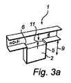
図3a〜図3dに続き、本発明の少なくとも1つの例示実施形態に従う投与原理をさらに説明する。本デバイス1の設計が、キャビティ5内での粉末2の脱凝集解体とそこからの粉末2の一掃排出作用期間中の剪断駆動キャビティ原理として示される現象の使用を規定することを理解されたい。相応しくは、流路4はデバイス3を通常操作用に位置決めしたときに流入口から吸い口への概ね水平な直線に従って配置される。流路は、キャビティの開口を通過する空気流をそのキャビティ開口外部に案内するよう配置してある。
Following FIGS. 3a-3d, the dosing principles according to at least one exemplary embodiment of the present invention will be further described. It should be understood that the design of the device 1 stipulates the use of the phenomenon shown as the shear driven cavity principle during the deagglomeration and dismantling of the
図3aには、適当な頭隙11をもって粉末2を充填したキャビティ5が開示されている。流路4に沿う空気流は流れ方向(F)にて始まり、キャビティ5の一掃排出が始まる。図3bに移るに、ここでは粉末2の一部がキャビティ5を去っている。キャビティ5内の渦空気流の堆積が始まり、キャビティ5は図3cへ移動する際に下流域およびさらなる上流において一掃排出されることが見てとれる。キャビティ5の一掃排出が完了する際の図3aの状況から図3dの状況までに経過する時間期間は、無論、流れの大きさと量、深さ、粉末組成、粉末深さ、頭隙等に依存する。少なくとも1つの例示実施形態では、脱凝集解体を含む一掃排出時間は30msからである。例えば、脱凝集解体を含む一掃排出時間は500msとすることができる。
FIG. 3 a discloses a
剪断駆動キャビティは、上側境界が所望の流れ方向(F)に移動し、その結果キャビティ5内にガス/空気の回転を生ずる場合のキャビティ5内の流れモデルとなる。流れは恐らく4000を越すレイノルズ数で発生し、よって上部境界流は一般的事例では乱流であると見なすことができる。このプロセス期間中のパターンは、実に複雑である。流路4の両側面は、流れ方向に互いに拡幅する広がりをもって配置されている。60個のキャビティを有する図5の実施形態によるディスクを有するデバイスは、流路の中心線に対し4度の角度で拡幅する流路の側壁を有することになる。
The shear drive cavity is the flow model in the
ディスクに30個のキャビティが備わる代替実施形態では、流路の側壁は流路の中心線に対し12度の角度で拡幅する。流路4は、キャビティ5に対し上流域内の上側と下側の平坦面領域の間に一定距離をもって形成することができる。さらに、キャビティ5に対する下流域内で流路4は上流域と同じ距離をもって形成することが望ましい。キャビティ領域内の流路4の断面形状もまた、同じように形成される。流路4の断面形状は、1〜5mmの範囲の寸法を有する矩形とすることができる。
In an alternative embodiment where the disk has 30 cavities, the side walls of the channel widen at an angle of 12 degrees relative to the centerline of the channel. The
本発明の第3実施形態によれば、本デバイスは薬剤粉末を有する1個のキャビティを含む一回吸入デバイスである。 According to a third embodiment of the invention, the device is a single inhalation device comprising one cavity with a drug powder.
矩形キャビティ5は、それらが適切な深さを有する限り魅力的である。これらのキャビティにとって、一掃排出時間と壁配置ファクタは深さの増大に合わせ増大すると予測される。脱凝集解体の潜在能力は深さが5mmを越えて増大するのに合わせ減少すると予測されるが、局所的な最大値は深さ4mm近傍に見いだされる。この深さは、傾斜壁を有するキャビティにとっても重要である。
The
流路に対するキャビティの向きは、一掃排出時間と脱凝集解体潜在能力に対し顕著な影響を有することが分かっている。キャビティの深さとキャビティ充填物の半径とチャネル高さは、一掃排出時間と脱凝集解体潜在能力とに対し軽微な影響しか持たないと予想される。流れの挙動の検分は、キャビティから逃避せんとする粉末2の粒子がキャビティに再進入しやすくなるようキャビティ5が空気流に影響するが故に、α>0のデバイス1により脱凝集解体が促されることを示唆している。キャビティ5から逃避できない粒子は、代わりにキャビティ5の下流壁に衝突し、そのことで脱凝集解体を引き起こす。α>0では粒子はキャビティから逃避しそうもないため、一掃排出時間はより長くなる。
It has been found that the orientation of the cavity relative to the flow path has a significant effect on the sweep-out time and deagglomeration potential. Cavity depth, cavity fill radius and channel height are expected to have only a minor effect on cleanout time and deagglomeration potential. Inspection of the flow behavior facilitates deagglomeration by the device 1 with α> 0 because the
上記に提示された実施形態の特徴は本発明の全態様の完全な説明ではなく、異なる実施形態からの特徴のさらなる組み合わせが特許請求の範囲記載の保護範囲内で想到可能であることを理解されたい。これ故、特許請求の範囲内の異なる実施形態に様々な特徴を複合し、本発明のさらなる態様を可能にすることができる。 It is understood that the features of the embodiments presented above are not a complete description of all aspects of the invention, and that further combinations of features from different embodiments are conceivable within the scope of protection of the claims. I want. Thus, various features may be combined in different embodiments within the scope of the claims to enable further aspects of the invention.
Claims (15)
Applications Claiming Priority (2)
| Application Number | Priority Date | Filing Date | Title |
|---|---|---|---|
| US1538307P | 2007-12-20 | 2007-12-20 | |
| PCT/SE2008/051488 WO2009082341A1 (en) | 2007-12-20 | 2008-12-18 | Device and method for deaggregating powder 854 |
Related Child Applications (1)
| Application Number | Title | Priority Date | Filing Date |
|---|---|---|---|
| JP2014090216A Division JP2014158950A (en) | 2007-12-20 | 2014-04-24 | Device and method for deaggregating powder 854 |
Publications (1)
| Publication Number | Publication Date |
|---|---|
| JP2011507593A true JP2011507593A (en) | 2011-03-10 |
Family
ID=40801454
Family Applications (3)
| Application Number | Title | Priority Date | Filing Date |
|---|---|---|---|
| JP2010539380A Pending JP2011507593A (en) | 2007-12-20 | 2008-12-18 | Apparatus and method for deagglomerating and disassembling powder 854 |
| JP2010539382A Expired - Fee Related JP5646341B2 (en) | 2007-12-20 | 2008-12-18 | Dosage device and method for mixing powder in airflow 537 |
| JP2014090216A Pending JP2014158950A (en) | 2007-12-20 | 2014-04-24 | Device and method for deaggregating powder 854 |
Family Applications After (2)
| Application Number | Title | Priority Date | Filing Date |
|---|---|---|---|
| JP2010539382A Expired - Fee Related JP5646341B2 (en) | 2007-12-20 | 2008-12-18 | Dosage device and method for mixing powder in airflow 537 |
| JP2014090216A Pending JP2014158950A (en) | 2007-12-20 | 2014-04-24 | Device and method for deaggregating powder 854 |
Country Status (12)
| Country | Link |
|---|---|
| US (5) | US9283337B2 (en) |
| EP (2) | EP2224984A4 (en) |
| JP (3) | JP2011507593A (en) |
| KR (2) | KR20100103834A (en) |
| CN (2) | CN101939040B (en) |
| AU (3) | AU2008341217B2 (en) |
| BR (2) | BRPI0821726A2 (en) |
| CA (2) | CA2710274A1 (en) |
| MX (2) | MX2010006657A (en) |
| NZ (2) | NZ586106A (en) |
| RU (2) | RU2492876C2 (en) |
| WO (2) | WO2009082343A1 (en) |
Families Citing this family (43)
| Publication number | Priority date | Publication date | Assignee | Title |
|---|---|---|---|---|
| US9006175B2 (en) | 1999-06-29 | 2015-04-14 | Mannkind Corporation | Potentiation of glucose elimination |
| JP4681231B2 (en) | 2002-03-20 | 2011-05-11 | マンカインド コーポレイション | Inhaler |
| BRPI0514263B8 (en) | 2004-08-20 | 2021-05-25 | Mannkind Corp | method for the synthesis of n-protected bis-3,6-[4-aminobutyl]-2,5-diketopiperazine n-protected |
| KR101306384B1 (en) | 2004-08-23 | 2013-09-09 | 맨카인드 코포레이션 | Diketopiperazine salts, diketomorpholine salts or diketodioxane salts for drug delivery |
| EP1928423B1 (en) | 2005-09-14 | 2015-12-09 | Mannkind Corporation | Method of drug formulation based on increasing the affinity of active agents for crystalline microparticle surfaces |
| WO2007098500A2 (en) | 2006-02-22 | 2007-08-30 | Mannkind Corporation | A method for improving the pharmaceutic properties of microparticles comprising diketopiperazine and an active agent |
| TW200833670A (en) * | 2006-12-20 | 2008-08-16 | Astrazeneca Ab | Novel compounds 569 |
| JP5570996B2 (en) | 2007-12-14 | 2014-08-13 | エアロデザインズ インコーポレイテッド | Delivery of aerosolizable foodstuffs |
| NZ586106A (en) * | 2007-12-20 | 2012-09-28 | Astrazeneca Ab | Device, typically for medicament powder, for deaggregating powder by passing air stream along flat region with recess of brick shape where eddy is generated |
| US8485180B2 (en) | 2008-06-13 | 2013-07-16 | Mannkind Corporation | Dry powder drug delivery system |
| CA2982550C (en) | 2008-06-13 | 2020-08-25 | Mannkind Corporation | A dry powder inhaler and system for drug delivery |
| CN102065942B (en) | 2008-06-20 | 2013-12-11 | 曼金德公司 | An interactive apparatus and method for real-time profiling of inhalation efforts |
| TWI494123B (en) | 2008-08-11 | 2015-08-01 | Mannkind Corp | Use of ultrarapid acting insulin |
| US8314106B2 (en) | 2008-12-29 | 2012-11-20 | Mannkind Corporation | Substituted diketopiperazine analogs for use as drug delivery agents |
| PL2405963T3 (en) | 2009-03-11 | 2014-04-30 | Mannkind Corp | Apparatus, system and method for measuring resistance of an inhaler |
| ES2943333T3 (en) | 2009-06-12 | 2023-06-12 | Mannkind Corp | Diketopiperazine microparticles with defined surface areas |
| RU2536826C2 (en) | 2009-07-01 | 2014-12-27 | Астразенека Аб | Delivery device and method for increasing powder supply into air flow |
| EP2496295A1 (en) | 2009-11-03 | 2012-09-12 | MannKind Corporation | An apparatus and method for simulating inhalation efforts |
| AU2011271097B2 (en) | 2010-06-21 | 2014-11-27 | Mannkind Corporation | Dry powder drug delivery system and methods |
| WO2012010877A2 (en) | 2010-07-21 | 2012-01-26 | Astrazeneca Ab | New device |
| BR112013001266A2 (en) | 2010-07-21 | 2019-09-24 | Astrazeneca Ab | inhaler |
| CN103826988B (en) * | 2011-04-01 | 2016-03-09 | 曼金德公司 | For the blister package of pharmaceutical kit |
| WO2012174472A1 (en) | 2011-06-17 | 2012-12-20 | Mannkind Corporation | High capacity diketopiperazine microparticles |
| JP6018640B2 (en) | 2011-10-24 | 2016-11-02 | マンカインド コーポレイション | Analgesic composition effective for alleviating pain, and dry powder and dry powder drug delivery system comprising the composition |
| US9282772B2 (en) | 2012-01-31 | 2016-03-15 | Altria Client Services Llc | Electronic vaping device |
| ITBO20120185A1 (en) * | 2012-04-06 | 2013-10-07 | Emodial S R L | ANTIMICROBIAL MEDICATION, ANTIMICROBIAL COMPOSITION AND ITS USE |
| US9802012B2 (en) * | 2012-07-12 | 2017-10-31 | Mannkind Corporation | Dry powder drug delivery system and methods |
| WO2014066856A1 (en) | 2012-10-26 | 2014-05-01 | Mannkind Corporation | Inhalable influenza vaccine compositions and methods |
| KR102391750B1 (en) | 2013-03-15 | 2022-04-28 | 맨카인드 코포레이션 | Microcrystalline diketopiperazine compositions and methods |
| CN105451716A (en) | 2013-07-18 | 2016-03-30 | 曼金德公司 | Heat-stable dry powder pharmaceutical compositions and methods |
| US11446127B2 (en) | 2013-08-05 | 2022-09-20 | Mannkind Corporation | Insufflation apparatus and methods |
| JP2016530030A (en) * | 2013-09-04 | 2016-09-29 | スリーエム イノベイティブ プロパティズ カンパニー | Dry powder inhaler and method |
| EP3104853B1 (en) | 2014-02-10 | 2019-10-02 | Respivant Sciences GmbH | Mast cell stabilizers treatment for systemic disorders |
| SI3104854T1 (en) | 2014-02-10 | 2020-09-30 | Respivant Sciences Gmbh | Mast cell stabilizers for lung disease treatment |
| US10307464B2 (en) | 2014-03-28 | 2019-06-04 | Mannkind Corporation | Use of ultrarapid acting insulin |
| US10561806B2 (en) | 2014-10-02 | 2020-02-18 | Mannkind Corporation | Mouthpiece cover for an inhaler |
| DE102014017409B4 (en) * | 2014-11-26 | 2016-06-09 | Klaus Dieter Beller | Single-dose powder inhaler and process for its preparation |
| SE539111C2 (en) | 2015-06-03 | 2017-04-11 | Iconovo Ab | Single dose dry powder inhaler |
| US10265296B2 (en) | 2015-08-07 | 2019-04-23 | Respivant Sciences Gmbh | Methods for the treatment of systemic disorders treatable with mast cell stabilizers, including mast cell related disorders |
| EP3331522A1 (en) | 2015-08-07 | 2018-06-13 | Patara Pharma LLC | Methods for the treatment of mast cell related disorders with mast cell stabilizers |
| EP3506893A4 (en) | 2016-08-31 | 2020-01-22 | Respivant Sciences GmbH | Cromolyn compositions for treatment of chronic cough due to idiopathic pulmonary fibrosis |
| WO2018067341A1 (en) | 2016-10-07 | 2018-04-12 | Patara Pharma, LLC | Cromolyn compositions for treatment of pulmonary fibrosis |
| CN111550475B (en) * | 2020-03-27 | 2021-12-07 | 中国航天空气动力技术研究院 | Reverse T-shaped concave cavity structure for transition control of boundary layer |
Citations (3)
| Publication number | Priority date | Publication date | Assignee | Title |
|---|---|---|---|---|
| JP2002537952A (en) * | 1999-03-10 | 2002-11-12 | グラクソ グループ リミテッド | Improvements on inhalation devices |
| JP2002542999A (en) * | 1999-04-24 | 2002-12-17 | グラクソ グループ リミテッド | Drug carrier |
| JP2007520247A (en) * | 2003-07-02 | 2007-07-26 | ファイザー・リミテッド | Dosing device |
Family Cites Families (89)
| Publication number | Priority date | Publication date | Assignee | Title |
|---|---|---|---|---|
| US2214032A (en) * | 1939-06-23 | 1940-09-10 | Walter B Stewart | Apparatus for administering powdered aluminum |
| DE2346914C3 (en) | 1973-09-18 | 1980-10-16 | Paul Ritzau Pari-Werk, Gmbh & Co, 8130 Starnberg | Powdered substance inhaler |
| US3872970A (en) | 1974-01-11 | 1975-03-25 | Lilly Co Eli | Child-resistant blister package |
| IT1017153B (en) | 1974-07-15 | 1977-07-20 | Isf Spa | APPARATUS FOR INHALATIONS |
| US4014336A (en) | 1975-01-13 | 1977-03-29 | Syntex Puerto Rico, Inc. | Inhalation device |
| US3948264A (en) | 1975-05-21 | 1976-04-06 | Mead Johnson & Company | Inhalation device |
| GB1521000A (en) | 1975-06-13 | 1978-08-09 | Syntex Puerto Rico Inc | Inhalation device |
| GB1598081A (en) | 1977-02-10 | 1981-09-16 | Allen & Hanburys Ltd | Inhaler device for dispensing medicaments |
| JPS57500862A (en) | 1979-10-30 | 1982-05-20 | ||
| ES506585A0 (en) | 1980-10-30 | 1982-09-01 | Riker Laboratories Inc | A DEVICE TO FACILITATE THE ORAL INHALATION OF MEDICINES IN THE FORM OF POWDER |
| US4849606A (en) | 1987-12-23 | 1989-07-18 | S. C. Johnson & Son, Inc. | Tamper-resistant container utilizing a flexible seal |
| US4946038A (en) | 1989-12-20 | 1990-08-07 | Rolland Eaton | Medicine container and cover therefor |
| GB9004781D0 (en) | 1990-03-02 | 1990-04-25 | Glaxo Group Ltd | Device |
| SE9002895D0 (en) | 1990-09-12 | 1990-09-12 | Astra Ab | INHALATION DEVICES FOR DISPENSING POWDERS I |
| GB9021433D0 (en) * | 1990-10-02 | 1990-11-14 | Atomic Energy Authority Uk | Power inhaler |
| US5042472A (en) | 1990-10-15 | 1991-08-27 | Merck & Co., Inc. | Powder inhaler device |
| JPH06504223A (en) * | 1991-08-15 | 1994-05-19 | デル・ボン・フランコ | inhaler |
| US5469843A (en) * | 1991-11-12 | 1995-11-28 | Minnesota Mining And Manufacturing Company | Inhalation device |
| GB2264237A (en) | 1992-02-05 | 1993-08-25 | Robert Edward Newell | An inhaler |
| DE4208880A1 (en) * | 1992-03-19 | 1993-09-23 | Boehringer Ingelheim Kg | SEPARATOR FOR POWDER INHALATORS |
| ATE142515T1 (en) | 1992-06-05 | 1996-09-15 | Hoechst Ag | INHALER |
| WO1994023772A2 (en) * | 1993-04-06 | 1994-10-27 | Minnesota Mining And Manufacturing Company | Deagglomerators for dry powder inhalers |
| US5921237A (en) | 1995-04-24 | 1999-07-13 | Dura Pharmaceuticals, Inc. | Dry powder inhaler |
| SE9502800D0 (en) | 1995-08-10 | 1995-08-10 | Astra Ab | Disposable inhalers |
| DE69617754T2 (en) | 1996-01-03 | 2002-08-08 | Glaxo Group Ltd | inhaler |
| US5694920A (en) | 1996-01-25 | 1997-12-09 | Abrams; Andrew L. | Inhalation device |
| US5699789A (en) * | 1996-03-11 | 1997-12-23 | Hendricks; Mark R. | Dry powder inhaler |
| SE9700423D0 (en) | 1997-02-07 | 1997-02-07 | Astra Ab | Disposable inhalers |
| SE9700421D0 (en) * | 1997-02-07 | 1997-02-07 | Astra Ab | Single dose inhalation I |
| US6006747A (en) | 1997-03-20 | 1999-12-28 | Dura Pharmaceuticals, Inc. | Dry powder inhaler |
| CA2212430A1 (en) * | 1997-08-07 | 1999-02-07 | George Volgyesi | Inhalation device |
| NL1008031C2 (en) | 1998-01-15 | 1999-07-21 | Pharmachemie Bv | Device for inhaling medicament. |
| US7371254B2 (en) * | 1998-01-23 | 2008-05-13 | Innercool Therapies, Inc. | Medical procedure |
| US6234169B1 (en) | 1998-08-14 | 2001-05-22 | Arthur Slutsky | Inhaler |
| GB9821791D0 (en) * | 1998-10-06 | 1998-12-02 | Sgs Thomson Microelectronics | Data transfer |
| US6858199B1 (en) * | 2000-06-09 | 2005-02-22 | Advanced Inhalation Research, Inc. | High efficient delivery of a large therapeutic mass aerosol |
| SE9904706D0 (en) | 1999-12-21 | 1999-12-21 | Astra Ab | An inhalation device |
| US6810872B1 (en) | 1999-12-10 | 2004-11-02 | Unisia Jecs Corporation | Inhalant medicator |
| US6427688B1 (en) | 2000-02-01 | 2002-08-06 | Dura Pharmaceuticals, Icn. | Dry powder inhaler |
| ATE366126T1 (en) * | 2000-03-10 | 2007-07-15 | Univ North Carolina | DRY POWDER INHALERS, MULTIDOSE DRY POWDER MEDICINE PACKS, CONTROL SYSTEMS AND METHODS |
| US6971383B2 (en) * | 2001-01-24 | 2005-12-06 | University Of North Carolina At Chapel Hill | Dry powder inhaler devices, multi-dose dry powder drug packages, control systems, and associated methods |
| US6948494B1 (en) * | 2000-05-10 | 2005-09-27 | Innovative Devices, Llc. | Medicament container with same side airflow inlet and outlet and method of use |
| PE20020066A1 (en) | 2000-06-23 | 2002-02-23 | Norton Healthcare Ltd | PREVIOUSLY MEASURED DOSE DEPOSIT FOR DRY POWDER INHALER ACTIVATED BY BREATH |
| US7080644B2 (en) | 2000-06-28 | 2006-07-25 | Microdose Technologies, Inc. | Packaging and delivery of pharmaceuticals and drugs |
| AUPR020400A0 (en) | 2000-09-19 | 2000-10-12 | Glaxo Wellcome Australia Ltd | Inhalation device |
| FI20002363A0 (en) * | 2000-10-27 | 2000-10-27 | Orion Yhtymae Oyj | powder inhaler |
| DE10057832C1 (en) * | 2000-11-21 | 2002-02-21 | Hartmann Paul Ag | Blood analysis device has syringe mounted in casing, annular mounting carrying needles mounted behind test strip and being swiveled so that needle can be pushed through strip and aperture in casing to take blood sample |
| US6722364B2 (en) * | 2001-01-12 | 2004-04-20 | Becton, Dickinson And Company | Medicament inhalation delivery devices and methods for using the same |
| EG24184A (en) | 2001-06-15 | 2008-10-08 | Otsuka Pharma Co Ltd | Dry powder inhalation system for transpulmonary |
| US6681768B2 (en) | 2001-06-22 | 2004-01-27 | Sofotec Gmbh & Co. Kg | Powder formulation disintegrating system and method for dry powder inhalers |
| JP4261351B2 (en) | 2001-09-19 | 2009-04-30 | アドヴェント ファーマセウティカルズ プロプライエタリー リミテッド | Inhaler |
| SE0104251D0 (en) | 2001-12-14 | 2001-12-14 | Astrazeneca Ab | Novel compounds |
| SE524957C2 (en) * | 2002-04-12 | 2004-11-02 | Microdrug Ag | Method for dividing and distributing in air of dry powder drug |
| SE525027C2 (en) * | 2002-04-12 | 2004-11-16 | Microdrug Ag | Device comprising a powder air grinder |
| AU2003267809A1 (en) | 2002-06-07 | 2003-12-22 | Sun Pharmaceutical Industries Limited | Powder inhaler |
| US6874647B2 (en) * | 2002-08-12 | 2005-04-05 | Owens-Illinois Closure Inc. | Plastic closure, closure and container package, and method of manufacture |
| CN1720072A (en) | 2002-12-02 | 2006-01-11 | 艾伯塔大学理事会 | Device and method for deagglomeration of powder for inhalation |
| GB2401548B (en) | 2003-05-13 | 2005-07-13 | Boots Healthcare Int Ltd | Improvements relating to vaporisers |
| EP1488819A1 (en) | 2003-06-16 | 2004-12-22 | Rijksuniversiteit te Groningen | Dry powder inhaler and method for pulmonary inhalation of dry powder |
| AU2004255029B2 (en) | 2003-07-09 | 2010-05-20 | Cipla Limited | Multi-dose inhaler |
| GB0322544D0 (en) | 2003-09-26 | 2003-10-29 | Innovata Biomed Ltd | Apparatus |
| GB2407042B (en) | 2003-10-17 | 2007-10-24 | Vectura Ltd | Inhaler |
| JP2007523700A (en) * | 2004-02-24 | 2007-08-23 | マイクロドース・テクノロジーズ・インコーポレーテッド | Flow direction detection inhaler |
| SE0401654D0 (en) * | 2004-06-24 | 2004-06-24 | Astrazeneca Ab | A support structure for a drug |
| WO2006010248A1 (en) * | 2004-07-26 | 2006-02-02 | 1355540 Ontario Inc. | Powder inhaler featuring reduced compaction inhaler |
| US7605168B2 (en) | 2004-09-03 | 2009-10-20 | Plexxikon, Inc. | PDE4B inhibitors |
| GB0427028D0 (en) | 2004-12-09 | 2005-01-12 | Cambridge Consultants | Dry powder inhalers |
| GB0427856D0 (en) | 2004-12-20 | 2005-01-19 | Glaxo Group Ltd | Maniflod for use in medicament dispenser |
| JP2008540264A (en) | 2005-05-02 | 2008-11-20 | アストラゼネカ・アクチエボラーグ | Configuration and method for opening a cavity, drug package and distribution device |
| US8763605B2 (en) | 2005-07-20 | 2014-07-01 | Manta Devices, Llc | Inhalation device |
| DE102005046645B3 (en) | 2005-09-29 | 2006-07-20 | Braunform Gmbh | Medical powder inhaler has at least two reservoir containers from which different powders can be separately forwarded into a metering unit so that they are mixed together when traveling along an inhalation tube |
| CA2626708A1 (en) | 2005-11-07 | 2007-05-31 | Alkermes, Inc. | Receptacle packaging with inhaler-accommodating geometry |
| EP1844806A1 (en) | 2006-04-13 | 2007-10-17 | Boehringer Ingelheim Pharma GmbH | Device for delivery of medicaments, magazine for medicaments, and method for withdrawing medicaments from a medicament chamber |
| DE102006043637A1 (en) | 2006-05-18 | 2007-11-22 | Boehringer Ingelheim Pharma Gmbh & Co. Kg | atomizer |
| GB0611656D0 (en) | 2006-06-13 | 2006-07-19 | Cambridge Consultants | Dry powder inhalers |
| WO2008008021A1 (en) | 2006-07-14 | 2008-01-17 | Astrazeneca Ab | Inhalation system and delivery device for the administration of a drug in the form of dry powder. |
| JP2009543860A (en) | 2006-07-19 | 2009-12-10 | アストラゼネカ・アクチエボラーグ | Novel tricyclic spiropiperidine compounds, their synthesis and their use as chemokine receptor activity modulators |
| GB0704928D0 (en) | 2007-03-14 | 2007-04-25 | Cambridge Consultants | Dry powder inhalers |
| JP5528336B2 (en) | 2007-07-06 | 2014-06-25 | マンタ デバイシス,エルエルシー | Delivery device and related method |
| WO2009008832A1 (en) | 2007-07-12 | 2009-01-15 | Astrazeneca Ab | Medicament containing structure, method and inhalation device comprising such structure |
| US20090084379A1 (en) | 2007-10-02 | 2009-04-02 | Baxter International Inc. | Dry powder inhaler |
| NZ586106A (en) | 2007-12-20 | 2012-09-28 | Astrazeneca Ab | Device, typically for medicament powder, for deaggregating powder by passing air stream along flat region with recess of brick shape where eddy is generated |
| NZ586655A (en) | 2008-01-23 | 2012-03-30 | Astrazeneca Ab | A medical dispenser with a display which is covered when dispensing action is in progress |
| CA2982550C (en) | 2008-06-13 | 2020-08-25 | Mannkind Corporation | A dry powder inhaler and system for drug delivery |
| AU2009302958B2 (en) | 2008-10-08 | 2012-07-12 | Astrazeneca Ab | Inhaler with indexing linked to movement of cover |
| JP5841429B2 (en) | 2008-10-08 | 2016-01-13 | アストラゼネカ・アクチエボラーグAstrazeneca Aktiebolag | Inhaler with audible indicator means |
| RU2536826C2 (en) | 2009-07-01 | 2014-12-27 | Астразенека Аб | Delivery device and method for increasing powder supply into air flow |
| BR112013001266A2 (en) | 2010-07-21 | 2019-09-24 | Astrazeneca Ab | inhaler |
| WO2012010877A2 (en) | 2010-07-21 | 2012-01-26 | Astrazeneca Ab | New device |
-
2008
- 2008-12-18 NZ NZ586106A patent/NZ586106A/en not_active IP Right Cessation
- 2008-12-18 NZ NZ586105A patent/NZ586105A/en not_active IP Right Cessation
- 2008-12-18 WO PCT/SE2008/051490 patent/WO2009082343A1/en active Application Filing
- 2008-12-18 EP EP08864819.1A patent/EP2224984A4/en not_active Withdrawn
- 2008-12-18 JP JP2010539380A patent/JP2011507593A/en active Pending
- 2008-12-18 WO PCT/SE2008/051488 patent/WO2009082341A1/en active Application Filing
- 2008-12-18 MX MX2010006657A patent/MX2010006657A/en not_active Application Discontinuation
- 2008-12-18 US US12/809,155 patent/US9283337B2/en active Active
- 2008-12-18 CN CN200880126221.6A patent/CN101939040B/en not_active Expired - Fee Related
- 2008-12-18 KR KR1020107016028A patent/KR20100103834A/en active IP Right Grant
- 2008-12-18 RU RU2010126838/14A patent/RU2492876C2/en not_active IP Right Cessation
- 2008-12-18 EP EP08864465.3A patent/EP2224983B1/en not_active Not-in-force
- 2008-12-18 RU RU2010126836/14A patent/RU2484852C2/en not_active IP Right Cessation
- 2008-12-18 AU AU2008341217A patent/AU2008341217B2/en not_active Ceased
- 2008-12-18 BR BRPI0821726-2A patent/BRPI0821726A2/en not_active IP Right Cessation
- 2008-12-18 CN CN2008801262201A patent/CN101965208B/en not_active Expired - Fee Related
- 2008-12-18 KR KR1020107016071A patent/KR101503560B1/en not_active IP Right Cessation
- 2008-12-18 CA CA2710274A patent/CA2710274A1/en not_active Abandoned
- 2008-12-18 US US12/809,157 patent/US8479729B2/en active Active
- 2008-12-18 JP JP2010539382A patent/JP5646341B2/en not_active Expired - Fee Related
- 2008-12-18 MX MX2010006658A patent/MX2010006658A/en not_active Application Discontinuation
- 2008-12-18 AU AU2008341216A patent/AU2008341216B2/en not_active Ceased
- 2008-12-18 BR BRPI0821648-7A patent/BRPI0821648A2/en not_active IP Right Cessation
- 2008-12-18 CA CA2708190A patent/CA2708190A1/en not_active Abandoned
-
2009
- 2009-07-01 US US12/496,525 patent/US8578933B2/en active Active
-
2010
- 2010-11-05 US US12/940,683 patent/US8151793B2/en active Active
-
2011
- 2011-04-05 AU AU2011201528A patent/AU2011201528B2/en not_active Ceased
-
2013
- 2013-10-11 US US14/051,975 patent/US20140096771A1/en not_active Abandoned
-
2014
- 2014-04-24 JP JP2014090216A patent/JP2014158950A/en active Pending
Patent Citations (3)
| Publication number | Priority date | Publication date | Assignee | Title |
|---|---|---|---|---|
| JP2002537952A (en) * | 1999-03-10 | 2002-11-12 | グラクソ グループ リミテッド | Improvements on inhalation devices |
| JP2002542999A (en) * | 1999-04-24 | 2002-12-17 | グラクソ グループ リミテッド | Drug carrier |
| JP2007520247A (en) * | 2003-07-02 | 2007-07-26 | ファイザー・リミテッド | Dosing device |
Also Published As
Similar Documents
| Publication | Publication Date | Title |
|---|---|---|
| JP2014158950A (en) | Device and method for deaggregating powder 854 | |
| JP5517367B2 (en) | Inhaler | |
| TWI517868B (en) | Inhaler | |
| JP5651233B2 (en) | Simple capsule-based inhaler | |
| PT1294421E (en) | Dry powder inhaler | |
| EP2448623B1 (en) | Dispenser and method for entraining powder in an airflow | |
| EP2617451B1 (en) | Drug delivery assembly, and single dose inhaler for dry powder drug delivery having such assembly | |
| AU2014200558A1 (en) | Dispenser and method for entraining powder in an airflow |
Legal Events
| Date | Code | Title | Description |
|---|---|---|---|
| A621 | Written request for application examination |
Free format text: JAPANESE INTERMEDIATE CODE: A621 Effective date: 20111104 |
|
| A131 | Notification of reasons for refusal |
Free format text: JAPANESE INTERMEDIATE CODE: A131 Effective date: 20130226 |
|
| A977 | Report on retrieval |
Free format text: JAPANESE INTERMEDIATE CODE: A971007 Effective date: 20130228 |
|
| A521 | Request for written amendment filed |
Free format text: JAPANESE INTERMEDIATE CODE: A523 Effective date: 20130522 |
|
| A02 | Decision of refusal |
Free format text: JAPANESE INTERMEDIATE CODE: A02 Effective date: 20131224 |