JP2011502016A - Balloon catheter - Google Patents
Balloon catheter Download PDFInfo
- Publication number
- JP2011502016A JP2011502016A JP2010531417A JP2010531417A JP2011502016A JP 2011502016 A JP2011502016 A JP 2011502016A JP 2010531417 A JP2010531417 A JP 2010531417A JP 2010531417 A JP2010531417 A JP 2010531417A JP 2011502016 A JP2011502016 A JP 2011502016A
- Authority
- JP
- Japan
- Prior art keywords
- balloon
- coupling surface
- balloon catheter
- adhesive
- catheter
- Prior art date
- Legal status (The legal status is an assumption and is not a legal conclusion. Google has not performed a legal analysis and makes no representation as to the accuracy of the status listed.)
- Pending
Links
Images


Classifications
-
- A—HUMAN NECESSITIES
- A61—MEDICAL OR VETERINARY SCIENCE; HYGIENE
- A61M—DEVICES FOR INTRODUCING MEDIA INTO, OR ONTO, THE BODY; DEVICES FOR TRANSDUCING BODY MEDIA OR FOR TAKING MEDIA FROM THE BODY; DEVICES FOR PRODUCING OR ENDING SLEEP OR STUPOR
- A61M25/00—Catheters; Hollow probes
- A61M25/10—Balloon catheters
- A61M25/1027—Making of balloon catheters
- A61M25/1034—Joining of shaft and balloon
Abstract
本発明は、バルーンカテーテルを提供するために、カテーテルへのバルーン壁の取り付けに関する。特に、バルーンの均一膨張を最適化するために、バルーン壁をカテーテルに接着剤することを含む。 The present invention relates to the attachment of a balloon wall to a catheter to provide a balloon catheter. In particular, it includes gluing the balloon wall to the catheter to optimize the uniform inflation of the balloon.
Description
本発明は、バルーンカテーテルを提供するための、カテーテルへのバルーン壁の取り付けに関する。特に、本発明は、バルーンの均一膨張を最適にするための、カテーテルへのバルーン壁の接着に関する。 The present invention relates to the attachment of a balloon wall to a catheter to provide a balloon catheter. In particular, the present invention relates to adhesion of a balloon wall to a catheter to optimize the uniform inflation of the balloon.
バルーンカテーテルは、人間の管孔内にカテーテルを保持するために多くの医療用途に使用されている。 Balloon catheters are used in many medical applications to hold a catheter within a human lumen.
用途の一形態は、肛門洗浄であり、その場合には、例えば、便秘を緩和し、蠕動を刺激し、コントラスト促進流体を導入し、排泄物を収集し、又は薬剤を導入するために、人の直腸及び腸下部へ流体が注入される。 One form of use is anal irrigation, in which case, for example, to relieve constipation, stimulate peristalsis, introduce contrast-enhancing fluids, collect excrement, or introduce drugs. Fluid is injected into the rectum and lower intestine.
特に子供用の小さいバルーンカテーテルについて、バルーンが一側へ膨出することによりテーテルが直腸の壁にぶつかることなく、バルーンは均一に膨張することが重要である。不均一な膨張は、カテーテルが典型的には膨張したバルーンよりも固いので、膨張したバルーンのシール(seal)を損傷しかつ/または使用者に不快感を与え、かつ直腸壁を引っ掻くことになる。 Particularly for small balloon catheters for children, it is important that the balloon be inflated uniformly without the taper hitting the rectal wall as the balloon inflates to one side. Non-uniform inflation will damage the inflated balloon seal and / or make the user uncomfortable and scratch the rectal wall because the catheter is typically stiffer than the inflated balloon .
バルーンの均一膨張を実現するために、多くの因子が関与する。一つの因子は、カテーテル本体へのバルーン壁の取り付けである。 Many factors are involved in achieving uniform balloon inflation. One factor is the attachment of the balloon wall to the catheter body.
通常知られているバルーン型の直腸カテーテルにおいて、バルーン壁は典型的にはカテーテルの長手延長部(長手)に沿って分配された二つの連結領域でカテーテル本体へ連結され、連結領域間のバルーン壁は膨張した部分である。
かかる結合は、例えば、バルーン壁とカテーテル本体間の連結領域に接着剤を塗布することにより行われる。他の実施形態として、溶接により結合するか、又は溶剤を使用してバルーン壁とカテーテル本体を部分的に溶融し結合点で共に融合する。
In commonly known balloon-type rectal catheters, the balloon wall is typically connected to the catheter body at two connecting regions distributed along the longitudinal extension (longitudinal) of the catheter, and the balloon wall between the connecting regions Is the expanded part.
Such bonding is performed, for example, by applying an adhesive to the connection region between the balloon wall and the catheter body. In other embodiments, the balloon walls and the catheter body are partially melted and fused together at the point of attachment, either by welding or using a solvent.
バルーン壁を付与後に接着剤が環状リングの形態でカテーテル本体上に塗布される。バルーン壁はカテーテル本体へ付勢されるに従って、接着剤が両側へ、即ち、長手方向にランダムパターンで押し出される。この結果、バルーンを膨張させるために気体又は液体が注入されるバルーン壁の長手方向における距離はカテーテルの周りで相当に変化する。大人用の標準寸法の代表的直腸カテーテルにおいて、そのような距離は数ミリ単位で均等に1センチ(cm)を超えるまで変化する。 After applying the balloon wall, an adhesive is applied on the catheter body in the form of an annular ring. As the balloon wall is urged against the catheter body, the adhesive is extruded in a random pattern on both sides, ie in the longitudinal direction. As a result, the longitudinal distance of the balloon wall into which gas or liquid is injected to inflate the balloon varies considerably around the catheter. In typical rectal catheters of standard dimensions for adults, such distances vary by several millimeters and evenly above 1 centimeter (cm).
特に、他の連結領域に接近する接着剤の内縁に沿った不均一分配は、場合によりバルーンの初期膨張及び/又はバルーンの最後の形状に影響を与える。 In particular, non-uniform distribution along the inner edge of the adhesive approaching other connecting areas can possibly affect the initial inflation of the balloon and / or the final shape of the balloon.
従って、過剰接着剤の流出を如何に制御するかによって、より一層均一に膨張したバルーンを提供できる。 Therefore, it is possible to provide a more uniformly inflated balloon depending on how to control the flow of excess adhesive.
同様に、溶接が採用される場合に、溶融した過剰溶接材料、例えば、フィルタ又はカテーテル本体の材料それ自体による溶接材はバルーン壁から離れる流出面へ誘導される。 Similarly, when welding is employed, molten excess weld material, such as weld material from the filter or catheter body material itself, is directed to the exit surface away from the balloon wall.
更に、バルーン壁とカテーテル本体を連結領域で結合するために溶剤を使用する場合、過剰溶剤は同様に流出面へ誘導される。 Furthermore, when using a solvent to join the balloon wall and the catheter body at the connection region, excess solvent is similarly directed to the outflow surface.
過剰接着剤の流出を制御することによって、より一層均一に膨張したバルーンを提供することを課題とする。 It is an object of the present invention to provide a balloon inflated more uniformly by controlling the flow of excess adhesive.
本発明は長軸に沿って延在する細長いカテーテル本体を含むバルーンカテーテルに関し、バルーン壁が少なくとも二つの環状連結領域において前記カテーテル本体に連結され、少なくとも一つの連結領域において前記バルーン壁は結合材により前記カテーテル本体に連結され、前記結合材は長軸を中心に第一半径を有しかつ長軸に沿って延在する環状に形成されたリムの第一結合面上に付与され、かつ第一結合面は対峙する連結領域へ向かう方向において第一結合面に対して所定角度を形成する流出面に連続し、流出面は第一半径から縮小半径に向かって延在する。 The present invention relates to a balloon catheter including an elongated catheter body extending along a long axis, wherein a balloon wall is connected to the catheter body in at least two annular connection regions, and the balloon wall is connected by a binding material in at least one connection region. Coupled to the catheter body, the coupling material is applied on a first coupling surface of an annularly formed rim having a first radius about the major axis and extending along the major axis; The coupling surface is continuous with the outflow surface that forms a predetermined angle with respect to the first coupling surface in the direction toward the opposing coupling region, and the outflow surface extends from the first radius toward the reduced radius.
本発明は、過剰結合材を流出面へ追い出すルートを提供して所望しない領域でバルーン壁へ過剰結合材が結合しないようにする。 The present invention provides a route to expel excess binder to the outflow surface to prevent the excess binder from bonding to the balloon wall in undesired areas.
上記説明から理解されるように、結合材は連結領域においてバルーン壁とバルーン本体とを結合するために使用する方法に依存して相違してよい。従って、結合材は、連結される両要素が共に接着される場合には接着剤であってよく、連結される要素が共に溶接される場合にはフィルタ若しくはカテーテル本体の余剰材料であってよく、又は連結される要素が共に結合されるために一部溶解するものである場合には溶剤であってよい。 As will be appreciated from the above description, the bonding material may differ depending on the method used to bond the balloon wall and the balloon body at the connection region. Thus, the binding material may be an adhesive when both connected elements are bonded together, and may be an excess material of the filter or catheter body when the connected elements are welded together, Alternatively, it may be a solvent if the elements to be joined are partly soluble to be joined together.
本明細書において、「リム」の用語は、カテーテルの長軸を中心とする環状部と理解されてよく、例えば、環状バンドの形態である。リムは、他の要素と共に、例えば、バルーン壁に結合される表面として使用するのに適した面を有する。 As used herein, the term “rim” may be understood as an annulus centered on the long axis of the catheter, for example, in the form of an annular band. The rim has a surface suitable for use with other elements, for example as a surface that is coupled to the balloon wall.
過剰結合材が一方の連結領域から、反対側にある若しくは対峙する、連通領域の方向へ向って流出する危険を減少するために、反対側の連結領域から離れる方向へ結合材を案内するためるガイド手段が少なくとも一方の連結領域上に設けられる。 A guide for guiding the binder in a direction away from the opposite connection area in order to reduce the risk of excess binder flowing out from one connection area towards or opposite the direction of the communication area. Means are provided on at least one of the connecting regions.
少なくとも一つのガイド手段は、反対側の連結領域の近位で少なくとも一つの結合面上に設けられた上昇した縁を含む。 The at least one guide means includes a raised edge provided on the at least one coupling surface proximal to the opposite coupling region.
ガイド手段は少なくとも一つの結合面上に形成された少なくとも一つのリムを含む。これは、バリアとしてリムを使用することにより結合材が流れる速度を制御するために使用される。 The guide means includes at least one rim formed on at least one coupling surface. This is used to control the velocity at which the binder flows by using the rim as a barrier.
大きな角度を付けることにより、流出面はバルーン壁からの結合材の迅速除去を可能にする。従って、流出面が結合面と形成する角度は20°を超えてよく、そのようにして結合面は第一半径から、反対側の連結領域に向かう方向において縮小半径に向かって傾斜している。 By providing a large angle, the outflow surface allows for rapid removal of the binder from the balloon wall. Thus, the angle that the outflow surface forms with the coupling surface may exceed 20 °, so that the coupling surface is inclined from the first radius towards the reduced radius in the direction towards the opposite coupling region.
上述のごとく、結合材料は接着剤であってよい。接着剤の粘度は、接着剤を如何にして剥がすかに影響を与え、所望しない領域のタイプ及び寸法に影響する。このような用途に使用される接着剤の粘度は、代表例として10.000cP未満である。 As described above, the bonding material may be an adhesive. The viscosity of the adhesive affects how the adhesive is peeled off and affects the type and size of the unwanted area. The viscosity of the adhesive used for such applications is typically less than 10.000 cP.
接着剤(結合材)及びその流れの均一制御のために、第一結合面は平面的であってよい。 For uniform control of the adhesive (bonding material) and its flow, the first bonding surface may be planar.
一実施形態において、結合面は長軸に平行である。このことは、接着剤(結合材)の両側への均一流を可能にする。 In one embodiment, the coupling surface is parallel to the major axis. This allows a uniform flow to both sides of the adhesive (bonding material).
選択的に、第一結合面は、長軸と共に角度を形成し、それにより第一結合面は反対連結領域から離れる長手方向において内側へ向かって傾斜している(tapers)。これがガイド手段として機能し、かつ過剰接着剤(結合材)の流出を可能にする。 Optionally, the first coupling surface forms an angle with the major axis so that the first coupling surface tapers inward in the longitudinal direction away from the opposite coupling region. This functions as a guide means and allows the excess adhesive (binding material) to flow out.
他の実施形態において、第一環状受け溝が第一結合面の少なくとも一側に形成されている。これは、過剰接着剤(結合材)を収集する容器を提供する。 In another embodiment, a first annular receiving groove is formed on at least one side of the first coupling surface. This provides a container for collecting excess adhesive (binder).
他の実施形態において、第二結合面は、第一結合面に対する第一環状受け溝の反対側で長手方向に設けられる。 In another embodiment, the second coupling surface is provided longitudinally on the opposite side of the first annular receiving groove with respect to the first coupling surface.
カテーテル本体は、射出成形されてよい。この方法は、カテーテル本体上に良好な表面及び縁の形成を可能にし、本発明に好適である。 The catheter body may be injection molded. This method allows the formation of good surfaces and edges on the catheter body and is suitable for the present invention.
次の説明において特記しない限り、「近位」の用語は、挿入装置が対応する他の遠位部に対して挿入されるときに、身体に近い方の部位を意味する。 Unless otherwise specified in the following description, the term “proximal” means a site closer to the body when the insertion device is inserted relative to the corresponding other distal portion.
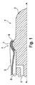
通常既知のバルーンカテーテル1の近位部が図1に示されている。バルーンカテーテルはカテーテル本体2と、連結領域4でカテーテル本体に連結されたバルーン壁3とで形成される。 The proximal portion of a commonly known balloon catheter 1 is shown in FIG. The balloon catheter is formed by a catheter body 2 and a balloon wall 3 connected to the catheter body at a connection region 4.
膨張チャンネル5は、膨張管孔6に連通し、管孔6へは膨張媒体(例えば、気体又は液体)が供給されてバルーン壁をバルーンカテーテルの長軸A−Aに対して半径方向に膨張させる。 The inflation channel 5 communicates with the inflation tube hole 6 and is supplied with an inflation medium (eg, gas or liquid) to inflate the balloon wall in a radial direction relative to the long axis AA of the balloon catheter. .
バルーン壁は連結領域でカテーテル本体に接着剤7により結合される。接着剤は環状リブ8の表面に塗布される。接着剤を接着するためにカテーテル本体に対してバルーン壁を付勢するにつれて、接着剤は外方へ流れ始める(即ち、長手方向)。断面図示されたように、接着剤はある領域でバルーン壁及びカテーテル本体に沿って他の領域よりも長く流れる。その結果、長手方向に接着剤の不均一分配が生じ、上述したように、バルーン壁の初期膨張そしてバルーン壁の最終膨張形態に影響を与える。 The balloon wall is bonded to the catheter body by an adhesive 7 at the connection region. The adhesive is applied to the surface of the annular rib 8. As the balloon wall is urged against the catheter body to adhere the adhesive, the adhesive begins to flow outward (ie, longitudinally). As shown in cross-section, the adhesive flows along the balloon wall and catheter body longer in some areas than in other areas. This results in a non-uniform distribution of the adhesive in the longitudinal direction, affecting the initial inflation of the balloon wall and the final inflation configuration of the balloon wall, as described above.
バルーンカテーテル51の一実施形態の近位部が図2に示されている。バルーンカテーテルは軸A−Aに沿って長手に延在する。遠位端はカテーテル本体52及びバルーン壁53を含み、バルーン壁は連結領域54で接着剤55を使用してカテーテルに連結されている。
The proximal portion of one embodiment of the
洗浄チャンネル56は、開口57を介して開放し、バルーンカテーテルにおける肛門洗浄キット(図示せず)の使用を可能にする。肛門洗浄の場合に、カテーテルは使用者の肛門管へ挿入される。挿入時に、バルーン壁は、気体又は液体を膨張チャンネル63を介して、バルーン壁53とカテーテル本体の外面と第一連結領域54と第一連結領域の遠位にある第二連結領域(図示せず)との間に形成された膨張管孔63へ注入することにより半径方向へ膨張する。カテーテルは、それにより、バルーン壁が肛門管の壁に対して付勢されるときに、保持される。洗浄流体は、そこで、開口57を介して洗浄チャンネル56から腸へ注入される。
The
環状リム58が、連結領域54に設けられている。環状リム58は平面的接着面59を形成する。平面性により、この表面は主にフラット、即ち、意図的カーブ又は不均衡はない。これにより、接着剤55は接着面上に均一層として付与される。
An annular rim 58 is provided in the
平面的接着面59は、移行縁60を介して第二連結領域へ向かう方向において流出面61へ続く。
The planar
移行縁60は、非常にシャープである。例えば、射出成形の場合に、器具はこの移行縁を形成し、かつ半径0.1ミリ(mm)の縁、又はそれ以下の半径を有する縁を形成する。ただし、バルーン壁に使用される材料に依存して、破壊発生の危険を伴うシャープ縁を有する移行縁が材料を加圧または切断することにより形成されてよい。従って、実施形態によって、移行縁は0.1を超える半径、即ち、0.5−5ミリ(mm)の範囲又はそれ以上の範囲の半径を有するものであってよい。
The
図2において、流出面61は、接着面59に対して90°の角度を形成する。接着面の外形に所定の良好変化を付与することにより、流出通路が形成され、過剰接着剤のバルーン壁から流出面61に沿った移動を可能にし、それにより、結果としてバルーンの不均一膨張に繋がる不要な接着を最小限にする。外形の変化は、更に、バルーン壁をカテーテル本体の外面から分離し、それにより、接着剤が不本意にバルーン壁の内面上又はカテーテル本体の外面上に付着する場合の接着を阻止する。
In FIG. 2, the
融合組立体を提供するために、バルーン壁はカテーテル本体内へ埋め込まれてよい。バルーン本体を受けるための凹部62を形成することにより、かかる埋め込みが可能である。凹部の深さは、バルーン壁の厚みに実質的に対応する。
In order to provide a fusion assembly, the balloon wall may be implanted into the catheter body. Such embedding is possible by forming a
バルーンの膨張形態に影響を与える因子の幾つかは次の通りである。 Some of the factors that affect balloon inflation are as follows.
長軸A−Aを参照して図示されたバルーンカテーテル51を観察すると、バルーン壁53はカテーテル本体52を中心とする管状部材であることが理解できる。
When the
膨張管孔63は、バルーン壁53、長軸に沿って見ると図示連結領域54の流出面61、図示されていない反対側の連結領域の流出面(図示されていない)、及びカテーテル本体の膨張面65により画定される。
The
流出面は長軸を中心に環状に構成され、内半径r1からカテーテル本体の中間半径r2へ垂直方向に拡張する。流出面は内半径r1において反対端で膨張面65に結合している。膨張面65は長軸を中心に環状に形成される。 The outflow surface is formed in an annular shape around the major axis, and extends vertically from the inner radius r1 to the intermediate radius r2 of the catheter body. The outflow surface is coupled to the expansion surface 65 at the opposite end at the inner radius r1. The expansion surface 65 is formed in an annular shape around the long axis.
中間半径r2で、流出面は平面的接着面と結合し、上述のごとく、その接着面を介してカテーテル本体はバルーン壁に取り付けられる。 With an intermediate radius r2, the outflow surface is joined to the planar adhesive surface, through which the catheter body is attached to the balloon wall.
平面的接着面は長軸に沿って流出面から凹面62へ延在する。上述の他の面により、平面的接着面は長軸A−Aを中心に環状に延在する。凹面62は中間半径r2から半径方向に拡張し、平面的接着面と共に外半径r3まで拡張してカテーテル本体52の外面と結合している。
A planar adhesive surface extends from the outflow surface to the
このようにして、膨張面は二つの接着面59(一方は図示されていない)間に介在し、接着面は膨張面の半径方向の広がりよりも半径方向に大きい広がりを有する。 In this way, the expansion surface is interposed between two bonding surfaces 59 (one not shown), and the bonding surface has a larger radial extent than the radial expansion of the expansion surface.
図3に示されたバルーンカテーテル100の第二実施形態において、平面的接着面101は、長軸A−Aと共に僅かな角度βを形成してよく、それにより流出面102と鋭角を形成し、流出面102から離れる方向において僅かに傾斜している(tapering)。
In the second embodiment of the
接着剤105は、基本的に傾斜方向へ移動し、それにより流出面上へ搾出される量を減少させる。 The adhesive 105 basically moves in the tilt direction, thereby reducing the amount squeezed onto the outflow surface.
図2に関して説明された面の半径方向の広がりは図3の実施形態にも適用できる。しかしながら、中間半径、即ち、長軸から平面的接着面までの半径は、平面的接着面が傾斜しているので、コンスタントではない。従って、その半径は流出面102が平面的接着面101と結合する点、即ち、半径が最大である点から、平面的接着面が凹面と結合する半径が最小となる点へ減少する。
The radial extent of the surface described with respect to FIG. 2 is also applicable to the embodiment of FIG. However, the intermediate radius, ie the radius from the major axis to the planar adhesive surface, is not constant because the planar adhesive surface is inclined. Accordingly, the radius decreases from the point where the
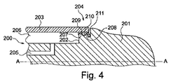
バルーンカテーテル200の第三実施形態は図4に断面で示されている。このバルーンカテーテルは、カテーテル本体201を含み、管状バルーン壁203が連結領域204でカテーテル本体に連結されている。
A third embodiment of the
膨張チャンネル205は、バルーン壁を半径方向外方へ膨張させるために、膨張気体又は液体を膨張管孔206へ供給する。
The
連結領域204において、バルーン壁203は第一平面的接着面207及び第二平面的接着面208へ接着剤209によって結合される。二つの接着面は環状受け溝210により分離されている。溝210は二つの接着面から流出する過剰接着剤を受ける役目をする。付加的受け溝211が第二接着面の遠位側に形成されて同様に過剰接着剤を受ける作用をする。
In the
図2の場合と同様に、第一平面的接着面は流出面212と90°の角度を形成する。 As in FIG. 2, the first planar adhesive surface forms an angle of 90 ° with the outflow surface 212.
図2−4を参照して説明されるバルーンカテーテルは、子供仕様に構成できる。その場合に重要なことは、バルーン壁が均一に膨張することである。かかるバルーンカテーテルは115ミリ(mm)の所定長(即ち、長軸A−Aに沿って)、及び11.5ミリ(mm)の直径を有してよい。バルーン壁は25ミリ(mm)の長手を有しかつ少なくとも70ミリ(mm)の直径に膨張してよい。当然ながら、バルーンカテーテルの他の実施形態が大人用、更には動物用に適当な寸法により提供され得る。 The balloon catheter described with reference to FIGS. 2-4 can be configured for children. What is important in that case is that the balloon wall expands uniformly. Such a balloon catheter may have a predetermined length of 115 mm (ie, along the long axis AA) and a diameter of 11.5 mm (mm). The balloon wall may have a length of 25 millimeters (mm) and expand to a diameter of at least 70 millimeters (mm). Of course, other embodiments of balloon catheters may be provided with suitable dimensions for adults and even animals.
カテーテル本体は熱可塑性ポリマーにより形成され、バルーン壁がポリクロロプレンラテックスにより形成されてよい。使用される接着剤はDymaxから販売されているMedi−Cure222(商品名)ゲルであってよい。 The catheter body may be formed from a thermoplastic polymer and the balloon wall may be formed from polychloroprene latex. The adhesive used may be Medi-Cure 222 (trade name) gel sold by Dymax.
接着面と流出面との間の角度は上述の一因子である。角度が鋭角であれば、それだけ接着剤は急速に輸送され、それにより接着面外でのバルーン壁への望ましくない接着を誘引する。 The angle between the adhesive surface and the outflow surface is a factor described above. The sharper the angle, the more rapidly the adhesive is transported, thereby inducing undesirable adhesion to the balloon wall outside the adhesive surface.
接着剤の粘度は、同様に、検討すべき一因子である。材料が低粘度の場合、移行縁の周りから流出面上への流出は容易である。ただし、低粘度接着剤は、同時に、制御が困難であり、接着面上に保持することが難しい。 The viscosity of the adhesive is also a factor to consider. If the material is of low viscosity, it is easy to flow out around the transition edge onto the outflow surface. However, the low-viscosity adhesive is simultaneously difficult to control and difficult to hold on the adhesive surface.
更に、上記実施形態の近位連結領域について説明されている。ただし、上述のごとく遠位連結は同様に行われるが、近位連結領域の特徴と同様であってよい。 Further, the proximal connection region of the above embodiment has been described. However, although the distal connection is performed in the same manner as described above, it may be the same as the characteristics of the proximal connection region.
図2から4の図示形態は、バルーン壁を有し、バルーン壁は長軸A−Aに平行に延在する。しかしながら、多くの場合に、バルーン壁は弛緩状態においてカテーテルよりも狭い直径を有する。従って、バルーン壁は、カテーテルのまわりに付与される場合に、その弾性及び可撓性によりカテーテルの外形に追従する。この結果として、例えば、未膨張状態では膨張容積は最小である。 The illustrated embodiment of FIGS. 2 to 4 has a balloon wall that extends parallel to the long axis AA. However, in many cases, the balloon wall has a narrower diameter than the catheter in the relaxed state. Thus, the balloon wall follows the contour of the catheter due to its elasticity and flexibility when applied around the catheter. As a result of this, for example, the expansion volume is minimal in the unexpanded state.
このように狭くなっているバルーン壁は、過剰結合材、例えば、接着剤の、バルーン壁とカテーテル本体間における分配の制御を更に一層困難にする。その理由は、バルーン壁は、カテーテルに付与される場合に、「飛び散り」効果を伴う、即ち、結合面から長手方向へ結合材をランダムに移動させることによる。 This narrowed balloon wall makes it even more difficult to control the distribution of excess bonding material, eg, adhesive, between the balloon wall and the catheter body. The reason is that when the balloon wall is applied to the catheter, it has a “scattering” effect, ie, randomly moving the binding material longitudinally from the binding surface.
従って、方向制御は特に望ましい。バルーン壁がカテーテルよりも狭い直径を有する場合に、例えば結合材を移動させるガイド手段を介して、結合材の移動方向を制御することが望ましい。かかる制御は、他の実施形態、例えば、上述のごとくバルーン壁の直径が狭くない場合にも、同様に望ましい。 Thus, directional control is particularly desirable. When the balloon wall has a narrower diameter than the catheter, it is desirable to control the moving direction of the binding material, for example, via a guide means for moving the binding material. Such control is also desirable in other embodiments, for example, when the balloon wall diameter is not narrow as described above.
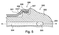
かかる狭い直径のバルーン壁を有するバルーンカテーテル500の一実施形態は図5に示されている。
One embodiment of a
筒状カテーテル本体502は近位先端503を有し、近位先端503は人の直腸管へカテーテルを導入するのに適した形状を有する。洗浄チャンネル504は洗浄開口505と連通し、そのようにして洗浄チャンネルから吸い上げられる洗浄流体は洗浄開口505を介して肛門管へ排出される。
The
カテーテル本体502は連結領域506においてバルーン壁501に連結される。
The
連結領域はカテーテル本体502上に設けられた環状結合面507を含む。接着剤508は、結合面507に付与されかつバルーン壁501とその結合面を連結する。
The connection region includes an
結合面507は膨張管孔510から結合面を分離する上昇縁509を有する。従って、バルーン壁が設置されかつ接着剤が移動するときに、上昇縁は接着剤が膨張管孔510へ流出する危険を減少させる。
The
バルーンカテーテル600の他の実施形態が図6に示されている。
Another embodiment of a
バルーン壁601は連結領域606においてカテーテル本体602へ取り付けられている。連結領域606において、結合面607は接着剤608を介してバルーン壁601に連結されている。
The
結合面607は、バルーン壁及びカテーテル本体により画定された膨張管孔609から離れる方向において内方へ傾斜している。従って、図3に示された実施形態と同様に、結合面607はバルーンカテーテルの長軸A−Aと共に角度βを形成し、結果として過剰接着剤を膨張管孔609から離れる方向へ案内する。
The coupling surface 607 is inclined inward in a direction away from the
図5を参照して説明された実施形態と同様に、結合面607は、膨張管孔609から結合面607を分離する上昇縁610を有する。従って、バルーン壁が付与されかつ接着剤が移動するときに、上昇縁は接着剤が膨張管孔609へ流出する危険を減少する。
Similar to the embodiment described with reference to FIG. 5, the coupling surface 607 has a rising
理解されるように、結合面607及び上昇縁610の傾斜は接着剤の移動を案内するガイド手段として機能し、そのようにして膨張管孔へ接着剤が流出しないようにする。ただし、接着剤の粘度に依り、ガイド手段は非常に効果的である。従って、幾らかの接着剤を遅延させかつ保持する小さいダムとしての働きをする二つの小さいリブ611a及び611bが形成されている。
As can be appreciated, the slope of the coupling surface 607 and the rising
1 バルーンカテーテル
2 カテーテル本体
3 バルーン壁
5 膨張チャンネル
6 膨張管孔
7 接着剤
51 バルーンカテーテル
52 カテーテル本体
53 バルーン壁
54 連結領域
55 接着剤
56 洗浄チャンネル
57 開口
58 環状リム
59 接着面
61 流出面
63 膨張管孔
500 バルーンカテーテル
501 バルーン壁
502 カテーテル本体
507 結合面
508 接着剤
DESCRIPTION OF SYMBOLS 1 Balloon catheter 2 Catheter main body 3 Balloon wall 5 Expansion channel 6 Expansion tube hole 7
Claims (12)
バルーン壁が少なくとも二つの環状連結領域において前記カテーテル本体に連結され、 前記連結領域の少なくとも一方において前記バルーン壁は結合材により前記カテーテル本体に結合され、
前記結合材は、長軸を中心に第一半径を有し長軸に沿って延在しかつ環状に形成されたリムの第一結合面上に付与され、かつ
前記結合面は、前記連結領域と反対の連結領域へ向かう方向において、第一結合面に対して所定角度を形成する流出面へ連続し、
前記流出面は第一半径から所定の縮小半径に向かって延在している、バルーンカテーテル。 A balloon catheter comprising an elongated catheter body extending along a major axis,
A balloon wall is connected to the catheter body in at least two annular connection regions, and the balloon wall is connected to the catheter body by a binding material in at least one of the connection regions;
The binding material is provided on a first coupling surface of a rim that has a first radius around a major axis and extends along the major axis and is formed in an annular shape, and the coupling surface includes the coupling region In the direction toward the connecting region opposite to the continuous outflow surface forming a predetermined angle with respect to the first coupling surface,
The balloon catheter, wherein the outflow surface extends from a first radius toward a predetermined reduced radius.
Applications Claiming Priority (2)
| Application Number | Priority Date | Filing Date | Title |
|---|---|---|---|
| DKPA200701571 | 2007-11-06 | ||
| PCT/DK2008/050269 WO2009059609A1 (en) | 2007-11-06 | 2008-11-06 | Balloon catheter |
Publications (1)
| Publication Number | Publication Date |
|---|---|
| JP2011502016A true JP2011502016A (en) | 2011-01-20 |
Family
ID=39535977
Family Applications (1)
| Application Number | Title | Priority Date | Filing Date |
|---|---|---|---|
| JP2010531417A Pending JP2011502016A (en) | 2007-11-06 | 2008-11-06 | Balloon catheter |
Country Status (7)
| Country | Link |
|---|---|
| US (1) | US20110015571A1 (en) |
| EP (1) | EP2207585A1 (en) |
| JP (1) | JP2011502016A (en) |
| CN (1) | CN101848743A (en) |
| AU (1) | AU2008324561A1 (en) |
| CA (1) | CA2704801A1 (en) |
| WO (1) | WO2009059609A1 (en) |
Families Citing this family (9)
| Publication number | Priority date | Publication date | Assignee | Title |
|---|---|---|---|---|
| EP2651314B1 (en) | 2010-12-15 | 2018-07-18 | Colospan Ltd. | Systems for bypassing an anastomosis site |
| US10463842B2 (en) | 2014-06-04 | 2019-11-05 | Cagent Vascular, Llc | Cage for medical balloon |
| JP2017535322A (en) | 2014-10-14 | 2017-11-30 | コロスパン リミテッドColospan Ltd. | Instrument for delivering a device to a hollow organ |
| WO2016073490A1 (en) | 2014-11-03 | 2016-05-12 | Cagent Vascular, Llc | Serration balloon |
| EP3331388B1 (en) * | 2015-08-07 | 2020-07-08 | Philip Morris Products S.a.s. | An aerosol-generating system with enhanced airflow management |
| EP3349837B1 (en) | 2015-09-17 | 2020-10-21 | Cagent Vascular, LLC | Wedge dissectors for a medical ballon |
| CN112384274B (en) * | 2018-06-14 | 2023-03-21 | 史赛克公司 | Balloon catheter assembly for inserting and positioning a therapeutic device within a vascular system |
| EP3826707A4 (en) * | 2018-07-25 | 2022-05-18 | Cagent Vascular, Inc. | Medical balloon catheters with enhanced pushability |
| US20220031342A1 (en) * | 2020-07-29 | 2022-02-03 | Neuravi Limited | Balloon Guide Catheter Having Reduced Outer Diameter Distal and Proximal Bonding Interface Areas With the Balloon |
Family Cites Families (17)
| Publication number | Priority date | Publication date | Assignee | Title |
|---|---|---|---|---|
| US3812860A (en) * | 1973-04-05 | 1974-05-28 | Int Paper Co | Retention catheter |
| US4003382A (en) * | 1975-07-25 | 1977-01-18 | Ethicon, Inc. | Retention catheter and method of manufacture |
| US4177815A (en) * | 1978-02-01 | 1979-12-11 | The Kendall Company | Catheter balloon structure |
| US4342316A (en) * | 1981-07-06 | 1982-08-03 | The Kendall Company | Zero stasis catheter |
| US4921483A (en) * | 1985-12-19 | 1990-05-01 | Leocor, Inc. | Angioplasty catheter |
| US5454788A (en) * | 1991-04-24 | 1995-10-03 | Baxter International Inc. | Exchangeable integrated-wire balloon catheter |
| US5195969A (en) * | 1991-04-26 | 1993-03-23 | Boston Scientific Corporation | Co-extruded medical balloons and catheter using such balloons |
| AU664187B2 (en) * | 1991-09-16 | 1995-11-09 | Cook Incorporated | Soft tip angioplasty balloon catheter |
| US5868704A (en) * | 1995-09-18 | 1999-02-09 | W. L. Gore & Associates, Inc. | Balloon catheter device |
| US5876376A (en) * | 1996-12-09 | 1999-03-02 | Medtronic, Inc | Catheter balloon bonding stopper |
| US5769819A (en) * | 1997-04-24 | 1998-06-23 | Medtronic, Inc. | Catheter distal tip component |
| JPH11192305A (en) * | 1997-12-26 | 1999-07-21 | Nippon Zeon Co Ltd | Balloon catheter and its production |
| US6319229B1 (en) * | 1998-02-19 | 2001-11-20 | Medtronic Percusurge, Inc. | Balloon catheter and method of manufacture |
| US20030135231A1 (en) * | 2002-01-17 | 2003-07-17 | Goodin Richardf L. | Catheter bond configuration |
| US7112357B2 (en) * | 2002-01-23 | 2006-09-26 | Boston Scientific Scimed, Inc. | Medical devices comprising a multilayer construction |
| US7575568B2 (en) * | 2003-12-10 | 2009-08-18 | Boston Scientific Scimed, Inc. | Catheter distal tip |
| US8298179B2 (en) * | 2004-12-22 | 2012-10-30 | Boston Scientific Scimed, Inc. | Catheter assembly with tapered joints and method of manufacture |
-
2008
- 2008-11-06 WO PCT/DK2008/050269 patent/WO2009059609A1/en active Application Filing
- 2008-11-06 AU AU2008324561A patent/AU2008324561A1/en not_active Abandoned
- 2008-11-06 CN CN200880114872A patent/CN101848743A/en active Pending
- 2008-11-06 US US12/741,595 patent/US20110015571A1/en not_active Abandoned
- 2008-11-06 CA CA2704801A patent/CA2704801A1/en not_active Abandoned
- 2008-11-06 JP JP2010531417A patent/JP2011502016A/en active Pending
- 2008-11-06 EP EP08847960A patent/EP2207585A1/en not_active Withdrawn
Also Published As
| Publication number | Publication date |
|---|---|
| CN101848743A (en) | 2010-09-29 |
| WO2009059609A1 (en) | 2009-05-14 |
| EP2207585A1 (en) | 2010-07-21 |
| CA2704801A1 (en) | 2009-05-14 |
| AU2008324561A1 (en) | 2009-05-14 |
| US20110015571A1 (en) | 2011-01-20 |
Similar Documents
| Publication | Publication Date | Title |
|---|---|---|
| JP2011502016A (en) | Balloon catheter | |
| JP6968072B2 (en) | Balloon catheter and its manufacturing method and usage method | |
| US5876376A (en) | Catheter balloon bonding stopper | |
| US5792105A (en) | Multichannel balloon catheter for delivering fluid | |
| US7951259B2 (en) | Balloon catheter having a flexible distal end | |
| US7996976B2 (en) | Retaining stent | |
| JP5061614B2 (en) | catheter | |
| EP0597506B1 (en) | Catheter equipped with expansible member and method of manufacturing the same | |
| CN103764217B (en) | The insertion top of conduit | |
| US20030032920A1 (en) | Catheter tip | |
| JP6348486B2 (en) | Balloon catheter and method for manufacturing balloon catheter | |
| JP4833039B2 (en) | catheter | |
| WO2001089412A2 (en) | Catheter having a tapered distal tip and method of making | |
| JP2017018209A (en) | Treatment instrument for endoscope and production method thereof | |
| US20200269023A1 (en) | Medical balloon assembly | |
| JP7301291B2 (en) | Catheter and oxygen partial pressure measurement method | |
| JP2017063830A (en) | Balloon catheter | |
| JPH0749959Y2 (en) | Balloon catheter | |
| WO2013122002A1 (en) | Balloon catheter | |
| MXPA97004547A (en) | Cateter and process for your manufacturer |